US9786022B2 - Customized patient-specific bone cutting blocks - Google Patents
Customized patient-specific bone cutting blocksDownload PDFInfo
- Publication number
- US9786022B2 US9786022B2US13/580,252US201113580252AUS9786022B2US 9786022 B2US9786022 B2US 9786022B2US 201113580252 AUS201113580252 AUS 201113580252AUS 9786022 B2US9786022 B2US 9786022B2
- Authority
- US
- United States
- Prior art keywords
- patient
- bone
- surgical
- specific orthopaedic
- indicia
- Prior art date
- Legal status (The legal status is an assumption and is not a legal conclusion. Google has not performed a legal analysis and makes no representation as to the accuracy of the status listed.)
- Active, expires
Links
Images


Classifications
- G—PHYSICS
- G06—COMPUTING OR CALCULATING; COUNTING
- G06Q—INFORMATION AND COMMUNICATION TECHNOLOGY [ICT] SPECIALLY ADAPTED FOR ADMINISTRATIVE, COMMERCIAL, FINANCIAL, MANAGERIAL OR SUPERVISORY PURPOSES; SYSTEMS OR METHODS SPECIALLY ADAPTED FOR ADMINISTRATIVE, COMMERCIAL, FINANCIAL, MANAGERIAL OR SUPERVISORY PURPOSES, NOT OTHERWISE PROVIDED FOR
- G06Q50/00—Information and communication technology [ICT] specially adapted for implementation of business processes of specific business sectors, e.g. utilities or tourism
- G06Q50/10—Services
- G06Q50/22—Social work or social welfare, e.g. community support activities or counselling services
- A—HUMAN NECESSITIES
- A61—MEDICAL OR VETERINARY SCIENCE; HYGIENE
- A61B—DIAGNOSIS; SURGERY; IDENTIFICATION
- A61B17/00—Surgical instruments, devices or methods
- A61B17/14—Surgical saws
- A61B17/15—Guides therefor
- A61B17/154—Guides therefor for preparing bone for knee prosthesis
- A61B17/155—Cutting femur
- A—HUMAN NECESSITIES
- A61—MEDICAL OR VETERINARY SCIENCE; HYGIENE
- A61B—DIAGNOSIS; SURGERY; IDENTIFICATION
- A61B17/00—Surgical instruments, devices or methods
- A61B17/14—Surgical saws
- A61B17/15—Guides therefor
- A61B17/154—Guides therefor for preparing bone for knee prosthesis
- A61B17/157—Cutting tibia
- G—PHYSICS
- G06—COMPUTING OR CALCULATING; COUNTING
- G06Q—INFORMATION AND COMMUNICATION TECHNOLOGY [ICT] SPECIALLY ADAPTED FOR ADMINISTRATIVE, COMMERCIAL, FINANCIAL, MANAGERIAL OR SUPERVISORY PURPOSES; SYSTEMS OR METHODS SPECIALLY ADAPTED FOR ADMINISTRATIVE, COMMERCIAL, FINANCIAL, MANAGERIAL OR SUPERVISORY PURPOSES, NOT OTHERWISE PROVIDED FOR
- G06Q30/00—Commerce
- G06Q30/06—Buying, selling or leasing transactions
- G06Q30/0601—Electronic shopping [e-shopping]
- G06Q30/0621—Electronic shopping [e-shopping] by configuring or customising goods or services
- G—PHYSICS
- G16—INFORMATION AND COMMUNICATION TECHNOLOGY [ICT] SPECIALLY ADAPTED FOR SPECIFIC APPLICATION FIELDS
- G16H—HEALTHCARE INFORMATICS, i.e. INFORMATION AND COMMUNICATION TECHNOLOGY [ICT] SPECIALLY ADAPTED FOR THE HANDLING OR PROCESSING OF MEDICAL OR HEALTHCARE DATA
- G16H20/00—ICT specially adapted for therapies or health-improving plans, e.g. for handling prescriptions, for steering therapy or for monitoring patient compliance
- G16H20/40—ICT specially adapted for therapies or health-improving plans, e.g. for handling prescriptions, for steering therapy or for monitoring patient compliance relating to mechanical, radiation or invasive therapies, e.g. surgery, laser therapy, dialysis or acupuncture
- A—HUMAN NECESSITIES
- A61—MEDICAL OR VETERINARY SCIENCE; HYGIENE
- A61B—DIAGNOSIS; SURGERY; IDENTIFICATION
- A61B17/00—Surgical instruments, devices or methods
- A61B17/56—Surgical instruments or methods for treatment of bones or joints; Devices specially adapted therefor
- A61B2017/568—Surgical instruments or methods for treatment of bones or joints; Devices specially adapted therefor produced with shape and dimensions specific for an individual patient
- A—HUMAN NECESSITIES
- A61—MEDICAL OR VETERINARY SCIENCE; HYGIENE
- A61B—DIAGNOSIS; SURGERY; IDENTIFICATION
- A61B34/00—Computer-aided surgery; Manipulators or robots specially adapted for use in surgery
- A61B34/10—Computer-aided planning, simulation or modelling of surgical operations
- A61B2034/108—Computer aided selection or customisation of medical implants or cutting guides
Definitions
- the present disclosurerelates generally to customized patient-specific orthopaedic surgical instruments and to methods, devices, and systems for fabricating and positioning such instruments.
- Joint arthroplastyis a well-known surgical procedure by which a diseased and/or damaged natural joint is replaced by a prosthetic joint.
- a typical knee prosthesisincludes a tibial tray, a femoral component, a polymer insert or bearing positioned between the tibial tray and the femoral component, and, in some cases, a polymer patella button.
- orthopaedic surgeonsuse a variety of orthopaedic surgical instruments such as, for example, cutting blocks, drill guides, milling guides, and other surgical instruments.
- the orthopaedic surgical instrumentsare generic with respect to the patient such that the same orthopaedic surgical instrument may be used on a number of different patients during similar orthopaedic surgical procedures.
- a method for a vendor to create a customized patient-specific orthopaedic instrument for a patient of a healthcare facility that is external to the vendorincludes receiving, from the healthcare facility external to the vendor, an instrument request that includes data relevant to a bone of the patient.
- a surgical design plan that has been customized for the patientis created, per data of the instrument request.
- the surgical design planincludes a preoperatively planned size of at least one bone chip produced as a result of a surgical resection of the bone of the patient consistent with the surgical design plan.
- a manufacturing machine located at the vendoris operated to fabricate the customized patient-specific orthopaedic instrument per data of the surgical design plan.
- Indiciais applied on an outer surface of the customized patient-specific orthopaedic instrument.
- the indiciais indicative of the preoperatively planned size of at least one bone chip produced as a result of a surgical resection of the bone of the patient consistent with the surgical design plan.
- the indiciamay be etched on the outer surface of the customized patient-specific orthopaedic instrument. Alternatively, it may be painted or engraved on the outer surface of the customized patient-specific orthopaedic instrument.
- the surgical design planmay be based upon the one or more medical images of the bone of the patient.
- the surgical design planmay include a preoperatively planned size of a distal medial bone chip produced as a result of a surgical resection of the distal medial portion of the patient's distal femur consistent with the surgical design plan, and a distal lateral bone chip produced as a result of a surgical resection of the distal lateral portion of the patient's distal femur consistent with the surgical design plan.
- the surgical design planmay include a preoperatively planned size of a posterior medial bone chip produced as a result of a surgical resection of the posterior medial portion of the patient's distal femur consistent with the surgical design plan, and a posterior lateral bone chip produced as a result of a surgical resection of the posterior lateral portion of the patient's distal femur consistent with the surgical design plan.
- the surgical design planmay include a preoperatively planned size of a bone chip produced as a result of a surgical resection of the proximal medial portion and the proximal lateral portion of the patient's proximal tibia consistent with the surgical design plan.
- the methodmay also include applying indicia indicative of a resection alignment line on the outer surface of the customized patient-specific orthopaedic instrument.
- a method of a fabricating a customized patient-specific cutting block for use in performing an orthopaedic surgical procedure on a bone of a patientincludes preoperatively planning the size of each of a plurality of bone chips produced as a result of use of the customized patient-specific orthopaedic instrument to cut the bone of the patient.
- the methodalso includes applying a plurality of indicia on an outer surface of the customized patient-specific orthopaedic instrument. Each of the plurality of indicia is indicative of one of the preoperatively planned sizes of the plurality of bone chips produced as a result of use of the customized patient-specific orthopaedic instrument to cut the bone of the patient.
- the indiciamay be etched on the outer surface of the customized patient-specific orthopaedic instrument. Alternatively, it may be painted or engraved on the outer surface of the customized patient-specific orthopaedic instrument.
- the surgical design planmay be based upon the one or more medical images of the bone of the patient.
- the indiciamay be indicative of a preoperatively planned size of a distal medial bone chip produced as a result of a surgical resection of the distal medial portion of the patient's distal femur consistent with the surgical design plan, and a distal lateral bone chip produced as a result of a surgical resection of the distal lateral portion of the patient's distal femur consistent with the surgical design plan.
- the indiciamay be indicative of a preoperatively planned size of a posterior medial bone chip produced as a result of a surgical resection of the posterior medial portion of the patient's distal femur consistent with the surgical design plan, and a posterior lateral bone chip produced as a result of a surgical resection of the posterior lateral portion of the patient's distal femur consistent with the surgical design plan.
- the indiciamay be indicative of a preoperatively planned size of a bone chip produced as a result of a surgical resection of the proximal medial portion and the p
- a customized patient-specific orthopaedic instrumentincludes a customized patient-specific cutting block that includes a body having a bone-facing surface that includes a negative contour configured to receive a portion of a patient's bone having a corresponding contour.
- the cutting blockalso includes a cutting slot. Indicia is applied to the body, with the indicia being indicative of a preoperatively planned size of at least one bone chip produced as a result of a surgical resection of a patient's bone through the cutting slot.
- the customized patient-specific cutting blockmay be embodied as a customized patient-specific femoral cutting block or a customized patient-specific tibial cutting block.
- FIG. 1is a simplified flow diagram of an algorithm for designing and fabricating a customized patient-specific orthopaedic surgical instrument
- FIG. 2is a simplified flow diagram of a method for generating a model of a patient-specific orthopaedic instrument
- FIG. 3is a simplified flow diagram of a method for scaling a reference contour
- FIGS. 4-6are three-dimensional model's of a patient's tibia
- FIG. 7-9are three-dimensional models of a patient's femur
- FIG. 10is an anterior elevation an embodiment of a customized patient-specific orthopaedic surgical instrument
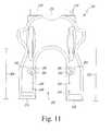
- FIG. 11is a top plan view of the customized patient-specific orthopaedic surgical instrument of FIG. 10 ;
- FIG. 12is side elevation view of the customized patient-specific orthopaedic surgical instrument of FIG. 10 ;
- FIG. 13is an anterior elevation view of another embodiment of a customized patient-specific orthopaedic surgical instrument
- FIG. 14is a top plan view of the customized patient-specific orthopaedic surgical instrument of FIG. 13 ;
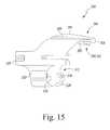
- FIG. 15is side elevation view of the customized patient-specific orthopaedic surgical instrument of FIG. 13 ;
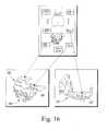
- FIG. 16is a diagrammatic view of showing a visual representation of a surgical design plan and a pair of customized patient-specific orthopaedic surgical instruments based thereon.
- anatomical referencessuch as anterior, posterior, medial, lateral, superior, inferior, etcetera
- terms representing anatomical referencesmay be used throughout this disclosure in reference to the orthopaedic implants and instruments described herein, along with a patient's natural anatomy. Such terms have well-understood meanings in both the study of anatomy and the field of orthopaedics. Use of such anatomical reference terms in the specification and claims is intended to be consistent with their well-understood meanings unless noted otherwise.
- customized patient-specific orthopaedic surgical instrumentis a surgical tool for use by a surgeon in performing an orthopaedic surgical procedure that is intended, and configured, for use on a particular patient.
- customized patient-specific orthopaedic surgical instrumentis distinct from standard, non-patient specific orthopaedic surgical instruments that are intended for use on a variety of different patients.
- customized patient-specific orthopaedic surgical instrumentis distinct from orthopaedic prostheses, whether patient-specific or generic, which are surgically implanted in the body of the patient. Rather, customized patient-specific orthopaedic surgical instruments are used by an orthopaedic surgeon to assist in the implantation of orthopaedic prostheses.
- the customized patient-specific orthopaedic surgical instrumentmay be customized to the particular patient based on the location at which the instrument is to be coupled to one or more bones of the patient, such as the femur and/or tibia.
- the customized patient-specific orthopaedic surgical instrumentmay include a bone-contacting or facing surface having a negative contour that matches or substantially matches the contour of a portion of the relevant bone of the patient.
- the customized patient-specific orthopaedic surgical instrumentis configured to be coupled to the bone of a patient in a unique location and position with respect to the patient's bone. That is, the negative contour of the bone-contacting surface is configured to receive the matching contour surface of the portion of the patient's bone.
- the orthopaedic surgeon's guesswork and/or intra-operative decision-making with respect to the placement of the orthopaedic surgical instrumentare reduced.
- the orthopaedic surgeonmay not be required to locate landmarks of the patient's bone to facilitate the placement of the orthopaedic surgical instrument, which typically requires some amount of estimation on part of the surgeon. Rather, the orthopaedic surgeon may simply couple the customized patient-specific orthopaedic surgical instrument on the bone or bones of the patient in the unique location.
- the cutting plane, drilling holes, milling holes, and/or other guidesare defined in the proper location relative to the bone and intended orthopaedic prosthesis.
- the customized patient-specific orthopaedic surgical instrumentmay be embodied as any type of orthopaedic surgical instrument such as, for example, a bone-cutting block, a drilling guide, a milling guide, or other type of orthopaedic surgical instrument configured to be coupled to a bone of a patient.
- the algorithm 10includes process steps 12 and 14 , in which an orthopaedic surgeon performs pre-operative planning of the orthopaedic surgical procedure to be performed on a patient.
- the process steps 12 and 14may be performed in any order or contemporaneously with each other.
- a number of medical images of the relevant bony anatomy or joint of the patientare generated.
- the orthopaedic surgeon or other healthcare providermay operate an imaging system to generate the medical images.
- the medical imagesmay be embodied as any number and type of medical images capable of being used to generate a three-dimensional rendered model of the patient's bony anatomy or relevant joint.
- the medical imagesmay be embodied as any number of computed tomography (CT) images, magnetic resonance imaging (MRI) images, or other three-dimensional medical images. Additionally or alternatively, as discussed in more detail below in regard to process step 18 , the medical images may be embodied as a number of X-ray images or other two-dimensional images from which a three-dimensional rendered model of the patient's relevant bony anatomy may be generated. Additionally, in some embodiments, the medical image may be enhanced with a contrast agent designed to highlight the cartilage surface of the patient's knee joint.
- CTcomputed tomography
- MRImagnetic resonance imaging
- the medical imagesmay be embodied as a number of X-ray images or other two-dimensional images from which a three-dimensional rendered model of the patient's relevant bony anatomy may be generated. Additionally, in some embodiments, the medical image may be enhanced with a contrast agent designed to highlight the cartilage surface of the patient's knee joint.
- the orthopaedic surgeonmay determine any additional pre-operative constraint data.
- the constraint datamay be based on the orthopaedic surgeon's preferences, preferences of the patient, anatomical aspects of the patient, guidelines established by the healthcare facility, or the like.
- the constraint datamay include the orthopaedic surgeon's preference for a metal-on-metal interface, amount of inclination for implantation, the thickness of the bone to resect, size range of the orthopaedic implant, and/or the like.
- the orthopaedic surgeon's preferencesare saved as a surgeon's profile, which may used as a default constraint values for further surgical plans.
- the medical images and the constraint dataare transmitted or otherwise provided to an orthopaedic surgical instrument vendor or manufacturer.
- the medical images and the constraint datamay be transmitted to the vendor via electronic means such as a network or the like.
- the vendorprocesses the images in step 18 .
- the orthopaedic surgical instrument vendor or manufacturerprocess the medical images to facilitate the determination of the bone cutting planes, implant sizing, and fabrication of the customized patient-specific orthopaedic surgical instrument as discussed in more detail below.
- the vendormay convert or otherwise generate three-dimensional images from the medical images.
- the vendormay use a suitable computer algorithm to generate one or more three-dimensional images form the number of two-dimensional images.
- the medical imagesmay be generated based on an established standard such as the Digital Imaging and Communications in Medicine (DICOM) standard.
- DICOMDigital Imaging and Communications in Medicine
- an edge-detection, thresholding, watershead, or shape-matching algorithmmay be used to convert or reconstruct images to a format acceptable in a computer aided design application or other image processing application.
- an algorithmmay be used to account for tissue such as cartilage not discernable in the generated medical images.
- any three-dimensional model of the patient-specific instrumentmay be modified according to such algorithm to increase the fit and function of the instrument.
- the vendormay process the medical images, and/or the converted/reconstructed images from process step 20 , to determine a number of aspects related to the bony anatomy of the patient such as the anatomical axis of the patient's bones, the mechanical axis of the patient's bone, other axes and various landmarks, and/or other aspects of the patient's bony anatomy. To do so, the vendor may use any suitable algorithm to process the images.
- the cutting planes of the patient's boneare determined.
- the planned cutting planesare determined based on the type, size, and position of the orthopaedic prosthesis to be used during the orthopaedic surgical procedure, on the process images such as specific landmarks identified in the images, and on the constraint data supplied by the orthopaedic surgeon in process steps 14 and 16 .
- the type and/or size of the orthopaedic prosthesismay be determined based on the patient's anatomy and the constraint data.
- the constraint datamay dictate the type, make, model, size, or other characteristic of the orthopaedic prosthesis.
- the selection of the orthopaedic prosthesismay also be modified based on the medical images such that an orthopaedic prosthesis that is usable with the bony anatomy of the patient and that matches the constraint data or preferences of the orthopaedic surgeon is selected.
- the planned location and position of the orthopaedic prosthesis relative to the patient's bony anatomyis determined.
- a digital template of the selected orthopaedic prosthesismay be overlaid onto one or more of the processed medical images.
- the vendormay use any suitable algorithm to determine a recommended location and orientation of the orthopaedic prosthesis (i.e., the digital template) with respect to the patient's bone based on the processed medical images (e.g., landmarks of the patient's bone defined in the images) and/or the constraint data. Additionally, any one or more other aspects of the patient's bony anatomy may be used to determine the proper positioning of the digital template.
- the digital template along with surgical alignment parametersmay be presented to the orthopaedic surgeon for approval.
- the approval documentmay include the implant's rotation with respect to bony landmarks such as the femoral epicondyle, posterior condyles, sulcus groove (Whiteside's line), and the mechanical axis as defined by the hip, knee, and/or ankle centers.
- the planned cutting planes for the patient's bone(s)may then be determined based on the determined size, location, and orientation of the orthopaedic prosthesis.
- other aspects of the patient's bony anatomy, as determined in process step 22may be used to determine or adjust the planned cutting planes.
- the determined mechanical axis, landmarks, and/or other determined aspects of the relevant bones of the patientmay be used to determine the planned cutting planes.
- the preoperative surgical design plan created by the vendorincludes a determination of the size of the bone chips that will be created when a surgeon executes the surgical design plan and resects the patient's bone along the planned cutting planes.
- a part of the surgical design planis to create a model that includes the individual sizes of the “bone scrap” created by proper execution of the surgical design plan.
- inclusion of the size of the bone chips created by proper execution of the surgical design planprovides a relatively easy way for the surgeon to confirm conformance with the surgical design plan.
- the surgical design planpreoperatively informs the surgeon that a proper resection of the distal lateral portion of the patient's femur along the planned cutting plane results in a distal lateral bone chip that is 11.0 mm thick
- the surgeoncan quickly and easily confirm his conformance with the surgical design plan by simply measuring the thickness of the distal lateral bone chip with, for example, a set of calipers after it has been resected from the patient's femur.
- the surgical design planmay include a model of the planned size of a distal medial bone chip produced as a result of a surgical resection of the distal medial portion of the patient's distal femur (DMF) consistent with the surgical design plan. It may also include the planned size of a distal lateral bone chip produced as a result of a surgical resection of the distal lateral portion of the patient's distal femur (DLF) consistent with the surgical design plan.
- the surgical design plan for use with a customized patient-specific femoral cutting blockmay also include the size of a posterior medial bone chip produced as a result of a surgical resection of the posterior medial portion of the patient's distal femur (PMF) consistent with the surgical design plan, and a posterior lateral bone chip produced as a result of a surgical resection of the posterior lateral portion of the patient's distal femur (PLF) consistent with the surgical design plan.
- PMFposterior medial bone chip produced as a result of a surgical resection of the posterior medial portion of the patient's distal femur
- PPFposterior lateral bone chip
- the surgical design planmay include a model of the planned size of the bone chip (or chips) produced as a result of a surgical resection of the proximal medial portion (MT) and the proximal lateral portion (LT) of the patient's proximal tibia consistent with the surgical design plan.
- a model of the customized patient-specific orthopaedic surgical instrumentis generated.
- the modelis embodied as a three-dimensional rendering of the customized patient-specific orthopaedic surgical instrument.
- the modelmay be embodied as a mock-up or fast prototype of the customized patient-specific orthopaedic surgical instrument.
- the particular type of orthopaedic surgical instrument to be modeled and fabricatedmay be determined based on the orthopaedic surgical procedure to be performed, the constraint data, and/or the type of orthopaedic prosthesis to be implanted in the patient.
- the customized patient-specific orthopaedic surgical instrumentmay be embodied as any type of orthopaedic surgical instrument for use in the performance of an orthopaedic surgical procedure.
- the orthopaedic surgical instrumentmay be embodied as a bone-cutting block, a drilling guide, a milling guide, and/or any other type of orthopaedic surgical tool or instrument.
- the particular shape of the customized patient-specific orthopaedic surgical instrumentis determined based on the planned location of the orthopaedic surgical instrument relative to the patient's bony anatomy.
- the location of the customized patient-specific orthopaedic surgical instrument with respect to the patient's bony anatomyis determined based on the type and determined location of the orthopaedic prosthesis to be used during the orthopaedic surgical procedure. That is, the planned location of the customized patient-specific orthopaedic surgical instrument relative to the patient's bony anatomy may be selected based on, in part, the planned cutting planes of the patient's bone(s) as determined in step 24 .
- the location of the orthopaedic surgical instrumentis selected such that the cutting guide of the bone-cutting block matches one or more of the planned cutting planes determined in process step 24 .
- the planned location of the orthopaedic surgical instrumentmay be based on the identified landmarks of the patient's bone identified in process step 22 .
- the particular shape or configuration of the customized patient-specific orthopaedic surgical instrumentmay be determined based on the planned location of the instrument relative to the patient's bony anatomy. That is, the customized patient-specific orthopaedic surgical instrument may include a bone-contacting surface having a negative contour that matches the contour of a portion of the bony anatomy of the patient such that the orthopaedic surgical instrument may be coupled to the bony anatomy of the patient in a unique location, which corresponds to the pre-planned location for the instrument.
- one or more guidese.g., cutting or drilling guide
- one or more guidesmay be aligned to one or more of the bone cutting plane(s) as discussed above.
- FIGS. 2 through 9One illustrative embodiment of a method 40 for generating a model, such as a computer model, of a patient-specific orthopaedic instrument is illustrated in FIGS. 2 through 9 .
- the method 40begins with a step 42 in which a cartilage thickness value is determined.
- the cartilage thickness valueis indicative of the average thickness of the cartilage of the patient's bone.
- the cartilage thickness valueis equal to the average thickness of cartilage for an individual having similar characteristics as the patient.
- the cartilage thickness valuemay be equal to the average thickness value of individuals of the same gender as the patient, the same age as the patient, having the same activity level of the patient, and/or the like.
- the cartilage thickness valueis determined based on one or more medical images of the patient's bone, such as those images transmitted in process step 16 .
- a reference contour of the patient's relevant boneis determined.
- the reference contouris based on the surface contour of a three-dimensional model of the patient's relevant bone, such as the three-dimensional model generated in step 20 .
- the reference contouris identical to a region (i.e. the region of interest such as the distal end of the patient's femur or the proximal end of the patient's tibia) of the patient's bone. That is, in some embodiments, the reference contour is juxtaposed on the surface contour of the region of the patient's bone.
- the reference contouris scaled to compensate for the cartilage thickness value determined in step 42 .
- the scale of the reference contouris increased based on the cartilage thickness value.
- the scale of the reference contourmay be increased by an amount equal to or determined from the cartilage thickness value.
- the reference contourmay be scaled using other techniques designed to scale the reference contour to a size at which the reference contour is compensated for the thickness of the cartilage on the patient's bone.
- the reference contouris scaled by increasing the distance between a fixed reference point and a point lying on, and defining in part, the reference contour.
- a method 60 for scaling a reference contour as illustrated in FIG. 3may be used.
- the method 60begins with step 62 in which a medial/lateral line segment is established on the three-dimensional model of the patient's relevant bone.
- the medial/lateral line segmentis defined or otherwise selected so as to extend from a point lying on the medial surface of the patient's bone to a point lying on lateral surface of the patient's bone.
- the medial surface point and the lateral surface pointmay be selected so as to define the substantially maximum local medial/lateral width of the patient's bone in some embodiments.
- an anterior/posterior line segmentis established on the three-dimensional model of the patient's relevant bone.
- the anterior/posterior line segmentis defined or otherwise selected so as to extend from a point lying on the anterior surface of the patient's bone to a point lying on posterior surface of the patient's bone.
- the anterior surface point and the posterior surface pointmay be selected so as to define the substantially maximum local anterior/posterior width of the patient's bone in some embodiments.
- the reference point from which the reference contour will be scaledis defined in step 66 as the intersection point of the medial/lateral line segment and anterior/posterior line segment.
- the medial surface point, the lateral surface point, the anterior surface point, and the posterior surface pointlie on the same plane.
- the reference pointis moved or otherwise translated toward an end of the patient's bone.
- the reference pointis moved inferiorly toward the distal end of the patient's femur.
- the reference pointis moved superiorly toward the proximal end of the patient's tibia.
- the reference pointis moved a distance equal to about half the length of the anterior/posterior line segment as determined in step 64 .
- the reference pointmay be moved other distances sufficient to compensate the reference contour for thickness of the cartilage present on the patient's bone.
- each point of the reference contouris moved a distance away from the reference point based on a percentage value of the original distance defined between the reference point and the particular point on the reference contour. For example, in one embodiment, each point lying on, and defining in part, the reference contour is moved away from the reference point in by a distance equal to a percentage value of the original distance between the reference point and the particular point. In one embodiment, the percentage value is in the range of about 5 percent to about thirty percent. In one particular embodiment, the percentage value is about ten percent.
- the reference contouris scaled by manually selecting a local “high” point on the surface contour of the three-dimensional image of the patient's bone.
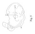
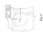
- the relevant patient's boneis embodied as a tibia as illustrated in FIGS. 4-6
- the reference point 90is initially located on the tibial plateau high point of the tibial model 92 . Either side of the tibial plateau may be used.
- the reference point 90is translated to the approximate center of the plateau as illustrated in FIG. 5 such that the Z-axis defining the reference point is parallel to the mechanical axis of the tibial model 92 .
- the reference pointis moved in the distal direction by a predetermined amount.
- the reference point is movedis the distal direction by about 20 millimeters, but other distances may be used in other embodiments.
- the distance over which the reference point is movedmay be based on the cartilage thickness value in some embodiments.
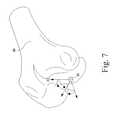
- the reference point 90is initially located on the most distal point of the distal end of the femoral model 94 .
- Either condyle of the femoral model 94may be used in various embodiments.
- the reference point 90is translated to the approximate center of the distal end of the femoral model 94 as illustrated in FIG. 8 such that the Z-axis defining the reference point 90 is parallel to the mechanical axis of the femoral model 92 .
- the anterior-posterior width 96 of the distal end of the femoral model 94is also determined.
- the reference pointis moved or otherwise translated in the proximal or superior direction by a distance 98 .
- the reference pointis moved in the distal or superior direction by a distance 98 equal to about half the distance 96 .
- a distance 98equal to about half the distance 96 .
- the medial/lateral sides of the reference contourare adjusted in step 48 .
- the distance between the reference point and each point lying on, and defining in part, the medial side and lateral side of the reference contouris decreased.
- the distance between the reference point and the points on the medial and lateral sides of the scaled reference contourare decreased to the original distance between such points.
- the reference contouris offset or otherwise enlarged with respect to the anterior side of the patient's bone and substantially matches or is otherwise not scaled with respect to the medial and lateral sides of the patient's bone.
- the reference contourmay also be adjusted in step 48 for areas of the patient's bone having a reduced thickness of cartilage. Such areas of reduced cartilage thickness may be determined based on the existence of bone-on-bone contact as identified in a medical image, simulation, or the like. Additionally, information indicative of such areas may be provided by the orthopaedic surgeon based on his/her expertise. If one or more areas of reduced cartilage thickness are identified, the reference contour corresponding to such areas of the patient's bone is reduced (i.e., scaled back or down).
- one or more osteophytes on the patient's bonemay be identified; and the reference contour may be compensated for such presence of the osteophytes. By compensating for such osteophytes, the reference contour more closely matches the surface contour of the patient's bone. Further, in some embodiments, a distal end (in embodiments wherein the patient's bone is embodied as a tibia) or a proximal end (in embodiments wherein the patient's bone is embodied as a femur) of the reference contour may be adjusted to increase the conformity of the reference contour to the surface contour of the bone.
- the superior end of the scaled reference contourmay be reduced or otherwise moved closer to the surface contour of the patient's femur in the region located superiorly to a cartilage demarcation line defined on the patient's femur.
- an inferior end of the scaled reference contourmay be reduced or otherwise moved closer to the surface contour of the patient's tibia in the region located inferiorly to a cartilage demarcation line of the patient's tibia.
- the scaled reference contouris initially enlarged to compensate for the thickness of the patient's cartilage on the patient's bone. Portions of the scaled reference contour are then reduced or otherwise moved back to original positions and/or toward the reference point in those areas where cartilage is lacking, reduced, or otherwise not present.
- the position of the cutting guideis defined in step 50 .
- the position of the cutting guideis defined based on an angle defined between a mechanical axis of the patient's femur and a mechanical axis of the patient's tibia. The angle may be determined by establishing a line segment or ray originating from the proximal end of the patient's femur to the distal end of the patient's femur and defining a second line segment or ray extending from the patient's ankle through the proximal end of the patient's tibia.
- the angle defined by these two line segments/raysis equal to the angle defined between the mechanical axis of the patient's femur and tibia.
- the position of the bone cutting guideis then determined based on the angle between the mechanical axes of the patient's femur and tibia. It should be appreciated that the position of the cutting guide defines the position and orientation of the cutting plane of the customized patient-specific cutting block.
- a negative contour of the customized patient-specific cutting blockis defined based on the scaled and adjusted reference contour and the angle defined between the mechanical axis of the femur and tibia.
- the modelis validated in process step 28 .
- the modelmay be validated by, for example, analyzing the rendered model while coupled to the three-dimensional model of the patient's anatomy to verify the correlation of cutting guides and planes, drilling guides and planned drill points, and/or the like. Additionally, the model may be validated by transmitting or otherwise providing the model generated in step 26 to the orthopaedic surgeon for review. For example, in embodiments wherein the model is a three-dimensional rendered model, the model along with the three-dimensional images of the patient's relevant bone(s) may be transmitted to the surgeon for review. In embodiments wherein the model is a physical prototype, the model may be shipped to the orthopaedic surgeon for validation.
- the customized patient-specific orthopaedic surgical instrumentis fabricated in process step 30 .
- the customized patient-specific orthopaedic surgical instrumentmay be fabricated using any suitable fabrication device and method. Additionally, the customized patient-specific orthopaedic instrument may be formed from any suitable material such as a metallic material, a plastic material, or combination thereof depending on, for example, the intended use of the instrument. In fabricating the instrument, customized patient-specific indicia may be applied to the instrument. For example, as noted above, the size of the bone chips produced by proper use of the instrument may be preoperatively determined to facilitate the surgeon's conformance to the surgical plan.
- Indicia indicative of the size of the bone chipsmay be applied (e.g., etched, painted, engraved, etcetera) to the outer surface of the instrument in an area near the cutting slot used to create the bone chip. Such indicia makes it easy for the surgeon to quickly ascertain the preoperatively determined size of the bone chip without having to refer to a document or display monitor.
- the fabricated customized patient-specific orthopaedic instrumentis subsequently shipped or otherwise provided to the orthopaedic surgeon.
- the surgeonperforms the orthopaedic surgical procedure in process step 32 using the customized patient-specific orthopaedic surgical instrument.
- the orthopaedic surgeondoes not need to determine the proper location of the orthopaedic surgical instrument intra-operatively, which typically requires some amount of estimation on part of the surgeon, the guesswork and/or intra-operative decision-making on part of the orthopaedic surgeon is reduced.
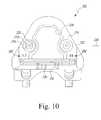
- the customized patient-specific orthopaedic surgical instrumentmay be embodied as a femoral cutting block 200 .
- the cutting block 200is configured to be coupled to a femur of a patient.
- the cutting block 200includes a body 202 configured to be coupled to the anterior side of the patient's femur and two arms or tabs 204 , 206 , which extend away from the body 202 in a posteriorly direction.
- the tabs 204 , 206are configured to wrap around a distal end of the femur as discussed in more detail below.
- Each of the tabs 204 , 206includes an inwardly-curving or otherwise superiorly extending lip 208 , 210 , respectively, which references the posterior condyles of the femur.
- the cutting block 200may be formed from any suitable material.
- the cutting block 200may be formed from a material such as a plastic or resin material.
- the cutting block 200is formed from Vero resin using a rapid prototype fabrication process.
- the cutting block 200may be formed from other materials in other embodiments.
- the cutting block 200is formed from a polyimide thermoplastic resin, such as a Ultem resin, which is commercially available from Saudi Basic Industries Corporation Innovative Plastics of Riyhadh, Saudi Arabia.
- the body 202includes a bone-contacting or bone-facing surface 212 and an outer surface 214 opposite the bone-facing surface 212 .
- the outer surface 214includes a number of guide holes or passageways 216 defined therethrough.
- a guide pin bushing 218is received in each guide hole 216 .
- the guide pin bushings 218include an internal passageway 220 sized to receive a respective guide pin to secure the block 200 to the patient's femur.
- the guide passageways 216extends from the outer surface 214 to the bone-facing surface 212 and is counterbored on the bone-facing surface 212 . That is, the passageway 216 has an opening 222 on the bone-facing surface 212 having a diameter greater than the diameter of an opening 224 on the outer surface 214
- the cutting block 200includes a cutting guide 230 secured to the body 202 .
- the cutting guide 230is overmolded to the body 202 .
- the cutting guide 230includes a cutting guide slot 232 .
- the cutting guide 230may be formed from the same material as the body 202 or from a different material.
- the cutting guide 230is formed from a metallic material such as stainless steel.
- the body 202also includes a window or opening 234 defined therethough. The opening 234 allows a surgeon to visualize the positioning of the block 200 on the patient's femur by viewing portions of the femur through the opening 234 . Additionally, the opening 234 may reduce the amount of air pockets or other perfections created during the fabrication of the block 200 .
- the opening 234extends from the cutting guide 200 to a point more superior than the superior-most point 236 of the guide pin bushings 218 .
- the cutting block 200may include windows or openings formed in the body 202 having other shapes and sizes.
- the bone-facing surface 212 of the body 202includes a negative contour 238 configured to receive a portion of the anterior side of the patient's femur having a corresponding contour.
- the customized patient-specific negative contour 238 of the bone-contacting surface 212allows the positioning of the cutting block 200 on the patient's femur in a unique pre-determined location and orientation.
- the tabs 204 , 206include a bone-contacting or bone-facing surface 240 , 242 , respectively, and an outer surface 244 , 246 , respectively, opposite the bone-facing surface 240 , 242 .
- the bone-facing surface 240 of the tab 204includes a negative contour 248 configured to receive a portion of the distal side of the patient's femur having a respective corresponding contour.
- the bone-facing surface 242 of the tab 206includes a negative contour 250 configured to receive a portion of the distal side of the patient's femur having a respective corresponding contour.
- the arms or tabs 204 , 206extend posteriorly from the body 200 to define a U-shaped opening 205 therebetween.
- the tabs 204 , 206may extend from the body 202 the same distance or a different distance.
- the tab 204extends from the body 202 a distance 252 and the tab 206 extends from the body 202 a distance 254 , which is less than the distance 252 .
- Each of the tabs 204 , 206includes a respective guide hole or passageway 260 defined therethrough.
- a guide pin bushing 262is received in each guide hole 260 .
- the guide pin bushings 262include an internal passageway 264 sized to receive a respective guide pin to further secure the block 200 to the patient's femur. Similar to the guide passageways 216 , the guide passageways 260 may be counterbored on the bone-facing surface 240 , 242 of the tabs 204 , 206 .
- the lips 208 , 210 of the tabs 204 , 206also include a bone-contacting or bone-facing surface 272 , 274 , respectively, and an outer surface 276 , 278 , respectively, opposite the bone-facing surface 272 , 274 .
- the bone-facing surface 272 of the lip 208includes a negative contour 280 configured to receive a portion of the posterior side of the patient's femur having a respective corresponding contour.
- the bone-facing surface 274 of the lip 210includes a negative contour 282 configured to receive a portion of the posterior side of the patient's femur having a respective corresponding contour.
- Each the lips 208 , 210include a lateral slot 284 that forms a saw relief slot and is configured to provide an amount of clearance for the bone saw blade used to remove a portion of the patient's bone. That is, during the performance of the orthopaedic surgical procedure, a distal end of the bone saw blade may be received in the slot 284 .
- the negative contours 238 , 248 , 250 , 280 , 282 of the bone-contacting surfaces 212 , 240 , 242 , 272 , 274 of the cutting block 200may or may not match the remaining corresponding contour surface of the patient's bone. That is, as discussed above, the negative contours 238 , 248 , 250 , 280 , 282 may be scaled or otherwise resized (e.g., enlarged) to compensate for the patient's cartilage or lack thereof.
- the femoral cutting block 200is fabricated based on a surgical design plan that includes, amongst many other things, a determination of the size of the bone chips that will be created when a surgeon resects the patient's femur with the cutting block 200 .
- the design plan used to fabricate the femoral cutting block 200includes a preoperatively determined size of a distal medial bone chip produced as a result of a surgical resection of the distal medial portion of the patient's distal femur (DMF) with the cutting block 200 .
- the surgical design plan used to fabricate the customized patient-specific femoral cutting block 200also includes the size of a posterior medial bone chip produced as a result of a surgical resection of the posterior medial portion of the patient's distal femur (PMF) by use of the cutting block 200 , and a posterior lateral bone chip produced as a result of a surgical resection of the posterior lateral portion of the patient's distal femur (PLF).
- Indicia indicative of the size of each preoperatively planned size of the bone chipis applied to an outer surface of the cutting block.
- indicia 292 indicative of the preoperatively planned size of a distal medial bone chip produced as a result of a surgical resection of the distal medial portion of the patient's distal femur (DMF) with the cutting block 200is applied to one of the outer medial surfaces of the body 202 of the cutting block 200 .
- Indicia 292 indicative of the preoperatively planned size of a distal medial bone chip produced as a result of a surgical resection of the distal lateral portion of the patient's distal femur (DLF) with the cutting block 200is applied to one of the outer lateral surfaces of the body 202 of the cutting block 200 .
- Indicia 292 indicative of the preoperatively planned size of a posterior medial bone chip produced as a result of a surgical resection of the posterior medial portion of the patient's distal femur (PMF) with the cutting block 200is applied to one of the outer medial or anterior surfaces of the body 202 of the cutting block 200 .
- Indicia 292 indicative of the preoperatively planned size of a posterior lateral bone chip produced as a result of a surgical resection of the posterior lateral portion of the patient's distal femur (PLF) with the cutting block 200is applied to one of the outer medial or anterior surfaces of the body 202 of the cutting block 200 .
- the indiciamay be applied to the body 202 of the cutting block 200 in a number of different manners.
- the indicia 292may be etched, painted, engraved, etcetera onto the body 202 of the cutting block 200 .
- the femoral cutting block 200is coupled to the distal end of the patient's femur.
- the block 200may be coupled to the patient's femur in a pre-planned, unique position.
- the tabs 204 , 206wrap around the distal end of the patient's femur and the lips 208 , 210 of the tabs 204 , 206 wrap around the posterior side of the patient's femur.
- the block 200when the block 200 is coupled to the patient's femur, a portion of the anterior side of the femur is received in the negative contour 238 of the body 202 , a portion of the distal side of the patient's femur is received in the negative contours 248 , 250 of the tabs 204 , 206 , and a portion of the posterior side of the femur is received in the negative contours 280 , 282 of the lips 208 , 210 .
- the anterior, distal, and posterior surfaces of the patient femurare referenced by the femoral cutting block 200 .
- the cutting block 200is used to resect the patient's bone along the preoperatively planned cutting planes. In doing so, the surgeon produces a distal medial bone chip as a result of resection of the distal medial portion of the patient's distal femur (DMF), and a distal lateral bone chip as a result of resection of the distal lateral portion of the patient's distal femur (DLF).
- DMFdistal medial bone chip
- DMFdistal lateral bone chip
- the surgeonalso produces a posterior medial bone chip as a result of a surgical resection of the posterior medial portion of the patient's distal femur (PMF), and a posterior lateral bone chip as a result of resection of the posterior lateral portion of the patient's distal femur (PLF).
- PMFposterior medial bone chip
- PPFposterior lateral bone chip
- theyare used to validate the surgeon's performance of the surgery in conformance with the preoperative surgical plan.
- the surgeonsince the surgeon is aware of the preoperatively determined size of each of the bone chips that are produced if the bone is resected along the preoperatively planned cutting planes, the surgeon can simply measure the actual bone chips created in the surgery and compare them to the preoperatively planned sizes.
- the surgeoncan measure the actual distal medial bone chip produced in the surgery with, for example, a pair of calipers to determine if the chip is, in fact, 7.5 mm. Confirmation of the size of the bone chip is used, therefore, the confirm a proper cut has been made. The surgeon may confirm all four bone chips made during surgical preparation of the patient's femur. If need be, the femur can then be re-cut to remove more bone.
- the customized patient-specific orthopaedic surgical instrumentmay be embodied as a tibial cutting block 300 .
- the cutting block 300is configured to be coupled to a tibia of a patient.
- the cutting block 300includes a body 302 configured to be coupled to the anterior side of the patient's tibia and two arms or tabs 304 , 306 , which extend away from the body 302 in a posteriorly direction.
- the tabs 304 , 306are configured to wrap over a proximal end of the tibia as discussed in more detail below.
- the cutting block 300may be formed from any suitable material.
- the cutting block 300may be formed from a material such as a plastic or resin material.
- the cutting block 300is formed from Vero resin using a rapid prototype fabrication process.
- the cutting block 300may be formed from other materials in other embodiments.
- the cutting block 300is formed from a polyimide thermoplastic resin, such as a Ultem resin, which is commercially available from Saudi Basic Industries Corporation Innovative Plastics of Riyhadh, Saudi Arabia.
- the body 302includes a bone-contacting or bone-facing surface 312 and an outer surface 314 opposite the bone-facing surface 312 .
- the outer surface 314includes a depression or recessed area 316 , which provides an indication to a surgeon where to apply pressure to the body 302 when coupling the cutting block 300 to the patient's tibia.
- a number of guide pin holes or passageways 318are defined through the body 302 and have a diameter sized to receive respective guide pins to secure the block 300 to the patient's tibia.
- one or more of the guide pin holes 318may be oblique or otherwise angled with respect to the remaining guide pin holes 318 to further secure the block 300 to the patient's bone.
- the body 302includes a modular cutting guide 320 . That is, the body 302 includes a cutting guide receiver slot 322 in which the cutting guide 320 is received. A latch 324 or other locking device secures the cutting guide 320 in place in the cutting guide receiver slot 322 .
- one of a number of different cutting guides 320 having a cutting guide slot 326 defined in various offset positionsmay be coupled to the body 302 to allow a surgeon to selectively determine the amount of bone of the patient's bone is removed during the bone cutting procedure.
- a cutting guide 320 having a cutting guide slot 326 offset by +2 millimeters, with respect to a neutral reference cutting guide 320may be used if the surgeon desires to remove a greater amount of the patient's bone.
- the cutting guide 320may be formed from the same material as the body 302 or from a different material. In one particular embodiment, the cutting guide 320 is formed form a metallic material such as stainless steel. It should be appreciated that the cutting block 300 may be embodied without a modular cutting guide 320 . That is, the cutting block 300 may be embodied with a fixed cutting guide 320 that is overmolded into the polymer body 302
- the bone-facing surface 312 of the body 302includes a negative contour 328 configured to receive a portion of the anterior side of the patient's tibia having a corresponding contour.
- the customized patient-specific negative contour 328 of the bone-contacting surface 312allows the positioning of the cutting block 300 on the patient's tibia in a unique pre-determined location and orientation.
- the arms or tabs 304 , 306extend posteriorly from the body 302 to define a U-shaped opening 305 therebetween.
- the tabs 304 , 306may extend from the body 302 the same distance or a different distance.
- the tab 304extends from the body 302 a distance 330 and the tab 306 extends from the body 302 a distance 332 , which is greater than the distance 330 .
- the tabs 304 , 306taper in the anterior-posterior direction.
- the thickness of the tabs 304 , 306 at an anterior end of the tabs 304 , 306is greater than the thickness of the tabs 304 , 306 at a respective posterior end 307 , 309 .
- the tapering of the tabs 304 , 306allow the tabs 304 , 306 to be inserted within the joint gap defined between the patient's femur and tibia.
- the tabs 304 , 306include a bone-contacting or bone-facing surface 340 , 342 , respectively, and an outer surface 344 , 346 , respectively, opposite the bone-facing surface 340 , 342 .
- the bone-facing surface 340 of the tab 304includes a negative contour 348 configured to receive a portion of the patient's proximal tibia having a respective corresponding contour.
- the bone-facing surface 342 of the tab 306includes a negative contour 350 configured to receive a portion of the patient's proximal tibia having a respective corresponding contour.
- the negative contours 328 , 348 , 350 of the bone-contacting surfaces 312 , 340 , 342 of the cutting block 300may or may not match the remaining corresponding contour surface of the patient's bone. That is, as discussed above, the negative contours 328 , 348 , 350 may be scaled or otherwise resized (e.g., enlarged) to compensate for the patient's cartilage or lack thereof.
- the tibial cutting block 300is fabricated based on a surgical design plan that includes, amongst many other things, a determination of the size of the bone chips that will be created when a surgeon resects the patient's tibia with the cutting block 300 .
- the design plan used to fabricate the tibial cutting block 300includes the preoperatively determined size of the bone chip (or chips) produced as a result of a surgical resection of the proximal medial portion (MT) and the proximal lateral portion (LT) of the patient's proximal tibia with the cutting block 300 .
- Indicia indicative of the size of such preoperatively planned bone chip(s)is applied to an outer surface of the cutting block 300 .
- indicia 390 indicative of the preoperatively planned size of a bone chip produced as a result of a surgical resection of the proximal medial portion (MT) and the proximal lateral portion (LT) of the patient's proximal tibia with the cutting block 300is applied to one of the outer anterior surfaces of the body 302 of the cutting block 300 .
- the indiciamay be applied to the body 302 of the cutting block 300 in a number of different manners.
- the indicia 390may be etched, painted, engraved, etcetera onto the body 302 of the cutting block 300 .
- the tibial cutting block 300is coupled to the proximal end of the patient's tibia.
- the block 300may be coupled to the patient's tibia in a pre-planned, unique position.
- the tabs 304 , 306wrap around the proximal end of the patient's tibia.
- the block 300when the block 300 is coupled to the patient's tibia, a portion of the anterior side of the tibia is received in the negative contour 328 of the body 302 and a portion of the proximal side of the patient's tibia is received in the negative contours 348 , 350 of the tabs 304 , 306 .
- the anterior and proximal surfaces of the patient tibiaare referenced by the tibial cutting block 300 .
- the cutting block 300is used to resect the patient's bone along the preoperatively planned cutting planes.
- the surgeonproduces a bone chip (or chips) as a result of a surgical resection of the proximal medial portion (MT) and the proximal lateral portion (LT) of the patient's proximal tibia.
- itis used to validate the surgeon's performance of the surgery in conformance with the preoperative surgical plan.
- the surgeonsince the surgeon is aware of the preoperatively determined size of the bone chip(s) produced if the tibia is resected along the preoperatively planned cutting plane(s), the surgeon can simply measure the actual bone chip(s) created in the surgery and compare it to the preoperatively planned size.
- a proper resection of the of the proximal medial portion (MT) and the proximal lateral portion (LT) of the patient's proximal tibiashould produce a bone chip that is 3.0 mm thick on the proximal medial side (MT) and 10.0 mm thick on the proximal lateral side (LT)
- the surgeoncan measure the actual bone chip produced in the surgery with, for example, a pair of calipers to determine if the chip is, in fact, 3.0 mm thick on the proximal medial side (MT) and 10.0 mm thick on the proximal lateral side (LT). Confirmation of the size of the bone chip is used, therefore, the confirm a proper cut has been made. If need be, the tibia can then be re-cut to remove more bone.
- a surgical design plancan be preoperatively designed in the manner described herein, including a determination of the sizes of the various bone chips that are to be created if a resection of the patient's bone is performed according to the plan.
- the planmay contemplate that the actual resection will be performed with standard instruments (i.e., instruments that are not customized for a particular patient).
- the surgical design planalone is the output from the preoperative design process.
- the planmay be transmitted to the surgeon via a printed document or electronic file, and, like the other plans described herein, may include electronic and/or visual representations of the plan's various features.
- the surgeonmay use information from the preoperatively designed surgical plan even though customized instruments are not being used. For example, the surgeon can utilize the preoperatively planned cutting planes to perform the cuts on the patient's bone. Moreover, the surgeon can save and thereafter measure the resultant bone chips to confirm the surgeon's conformance with the plan.
Landscapes
- Health & Medical Sciences (AREA)
- Surgery (AREA)
- Engineering & Computer Science (AREA)
- Life Sciences & Earth Sciences (AREA)
- Business, Economics & Management (AREA)
- General Health & Medical Sciences (AREA)
- Nuclear Medicine, Radiotherapy & Molecular Imaging (AREA)
- Medical Informatics (AREA)
- Public Health (AREA)
- Finance (AREA)
- Accounting & Taxation (AREA)
- Molecular Biology (AREA)
- Transplantation (AREA)
- Dentistry (AREA)
- Oral & Maxillofacial Surgery (AREA)
- Physical Education & Sports Medicine (AREA)
- Biomedical Technology (AREA)
- Heart & Thoracic Surgery (AREA)
- Orthopedic Medicine & Surgery (AREA)
- Animal Behavior & Ethology (AREA)
- Veterinary Medicine (AREA)
- General Physics & Mathematics (AREA)
- Physics & Mathematics (AREA)
- Theoretical Computer Science (AREA)
- General Business, Economics & Management (AREA)
- Economics (AREA)
- Marketing (AREA)
- Strategic Management (AREA)
- Development Economics (AREA)
- Primary Health Care (AREA)
- Epidemiology (AREA)
- Urology & Nephrology (AREA)
- Surgical Instruments (AREA)
- Prostheses (AREA)
- Tourism & Hospitality (AREA)
- Child & Adolescent Psychology (AREA)
- Human Resources & Organizations (AREA)
Abstract
Description
Claims (18)
Priority Applications (1)
| Application Number | Priority Date | Filing Date | Title |
|---|---|---|---|
| US13/580,252US9786022B2 (en) | 2007-09-30 | 2011-02-23 | Customized patient-specific bone cutting blocks |
Applications Claiming Priority (9)
| Application Number | Priority Date | Filing Date | Title |
|---|---|---|---|
| US97644407P | 2007-09-30 | 2007-09-30 | |
| US97645107P | 2007-09-30 | 2007-09-30 | |
| US97644707P | 2007-09-30 | 2007-09-30 | |
| US97644607P | 2007-09-30 | 2007-09-30 | |
| US97644807P | 2007-09-30 | 2007-09-30 | |
| US12/240,994US8425524B2 (en) | 2007-09-30 | 2008-09-29 | Customized patient-specific multi-cutting blocks |
| US30818910P | 2010-02-25 | 2010-02-25 | |
| US13/580,252US9786022B2 (en) | 2007-09-30 | 2011-02-23 | Customized patient-specific bone cutting blocks |
| PCT/US2011/025932WO2011106430A1 (en) | 2010-02-25 | 2011-02-23 | Customized patient-specific bone cutting blocks |
Related Parent Applications (1)
| Application Number | Title | Priority Date | Filing Date |
|---|---|---|---|
| US12/240,994Continuation-In-PartUS8425524B2 (en) | 2007-09-30 | 2008-09-29 | Customized patient-specific multi-cutting blocks |
Publications (2)
| Publication Number | Publication Date |
|---|---|
| US20140200902A1 US20140200902A1 (en) | 2014-07-17 |
| US9786022B2true US9786022B2 (en) | 2017-10-10 |
Family
ID=44507189
Family Applications (1)
| Application Number | Title | Priority Date | Filing Date |
|---|---|---|---|
| US13/580,252Active2031-06-13US9786022B2 (en) | 2007-09-30 | 2011-02-23 | Customized patient-specific bone cutting blocks |
Country Status (4)
| Country | Link |
|---|---|
| US (1) | US9786022B2 (en) |
| EP (1) | EP2538864B1 (en) |
| ES (1) | ES2704658T3 (en) |
| WO (1) | WO2011106430A1 (en) |
Cited By (5)
| Publication number | Priority date | Publication date | Assignee | Title |
|---|---|---|---|---|
| US20130066319A1 (en)* | 2010-02-25 | 2013-03-14 | Luke J. Aram | Method of fabricating customized patient-specific bone cutting blocks |
| US10828046B2 (en) | 2007-09-30 | 2020-11-10 | DePuy Synthes Products, Inc. | Apparatus and method for fabricating a customized patient-specific orthopaedic instrument |
| US11051829B2 (en) | 2018-06-26 | 2021-07-06 | DePuy Synthes Products, Inc. | Customized patient-specific orthopaedic surgical instrument |
| US11931106B2 (en) | 2019-09-13 | 2024-03-19 | Treace Medical Concepts, Inc. | Patient-specific surgical methods and instrumentation |
| US11986251B2 (en) | 2019-09-13 | 2024-05-21 | Treace Medical Concepts, Inc. | Patient-specific osteotomy instrumentation |
Families Citing this family (14)
| Publication number | Priority date | Publication date | Assignee | Title |
|---|---|---|---|---|
| WO2011106430A1 (en) | 2010-02-25 | 2011-09-01 | Depuy Products, Inc | Customized patient-specific bone cutting blocks |
| AU2013296108B2 (en) | 2012-07-24 | 2017-08-31 | Orthosoft Ulc | Patient specific instrumentation with mems in surgery |
| CN104684491B (en) | 2012-08-09 | 2019-02-22 | 史密夫和内修有限公司 | Patient Matched Devices |
| US9299138B2 (en)* | 2013-03-14 | 2016-03-29 | DePuy Synthes Products, Inc. | Generating a patient-specific orthopaedic surgical plan from medical image data |
| EP3288470B1 (en)* | 2015-04-28 | 2021-04-07 | Brainlab AG | Method and device for determining geometric parameters for total knee replacement surgery |
| ITUB20154673A1 (en)* | 2015-10-14 | 2017-04-14 | Riva Gian Guido | 4-IN-1 CUTTING MASK FOR FEMORAL FINISHING |
| WO2017186255A1 (en)* | 2016-04-26 | 2017-11-02 | Hafez Mahmoud Alm El Din | An apparatus and system for acquiring data from bones and joints, plan surgery and manufacture instruments or implants |
| US10398417B2 (en)* | 2016-06-29 | 2019-09-03 | DePuy Synthes Products, Inc. | Systems and methods for manufacturing custom surgical instruments |
| US10874404B2 (en) | 2016-12-30 | 2020-12-29 | DePuy Synthes Products, Inc. | Customized patient-specific surgical instruments and method |
| US10251654B2 (en) | 2016-12-30 | 2019-04-09 | DePuy Synthes Products, Inc. | Customized patient-specific surgical instrument with metallic insert |
| US10537343B2 (en) | 2018-01-24 | 2020-01-21 | DePuy Synthes Products, Inc. | Low-profile metallic customized patient-specific orthopaedic surgical instruments |
| US10631878B2 (en) | 2018-01-24 | 2020-04-28 | DePuy Synthes Products, Inc. | Customized patient-specific anterior-posterior chamfer block and method |
| US10716581B2 (en) | 2018-01-24 | 2020-07-21 | DePuy Synthes Products, Inc. | Method of designing and manufacturing low-profile customized patient-specific orthopaedic surgical instruments |
| US11376054B2 (en) | 2018-04-17 | 2022-07-05 | Stryker European Operations Limited | On-demand implant customization in a surgical setting |
Citations (242)
| Publication number | Priority date | Publication date | Assignee | Title |
|---|---|---|---|---|
| US3298410A (en) | 1964-01-31 | 1967-01-17 | Morifuji Haguruma Seisakusho C | Screw holder structure for use with screw drivers |
| US3816855A (en) | 1971-06-01 | 1974-06-18 | Nat Res Dev | Knee joint prosthesis |
| US3901298A (en) | 1974-04-05 | 1975-08-26 | John B Eby | Fastener holding attachment |
| US3965950A (en) | 1975-03-20 | 1976-06-29 | Macdonald Murdo A | Fastener driver and fastener holding nosepiece |
| US4055862A (en) | 1976-01-23 | 1977-11-01 | Zimmer Usa, Inc. | Human body implant of graphitic carbon fiber reinforced ultra-high molecular weight polyethylene |
| US4140161A (en) | 1977-06-15 | 1979-02-20 | Minnesota Mining And Manufacturing Company | Screw holding and driving device |
| US4197886A (en) | 1977-09-06 | 1980-04-15 | Clyde Corporation | Fastener driving tool and fastener holding nosepiece |
| EP0097001A1 (en) | 1982-06-03 | 1983-12-28 | Cemax Medical Products, Inc. | Method of forming implantable prostheses for reconstructive surgery |
| DE3339259C1 (en) | 1983-10-28 | 1985-03-14 | Reinhold 8000 München Schmieding | Device for the positioning of a surgical drilling tool |
| US4719907A (en) | 1987-03-18 | 1988-01-19 | Orthospec, Inc. | Orthopedic pin placement guide |
| US4721104A (en) | 1985-12-02 | 1988-01-26 | Dow Corning Wright Corporation | Femoral surface shaping apparatus for posterior-stabilized knee implants |
| US4759350A (en) | 1986-10-17 | 1988-07-26 | Dunn Harold K | Instruments for shaping distal femoral and proximal tibial surfaces |
| US4787383A (en) | 1985-12-19 | 1988-11-29 | Howmedica, Inc. | Prosthetic knee implantation |
| US4834080A (en) | 1987-09-11 | 1989-05-30 | Brown Byron L | Drill bit guide |
| US4841975A (en) | 1987-04-15 | 1989-06-27 | Cemax, Inc. | Preoperative planning of bone cuts and joint replacement using radiant energy scan imaging |
| US4860735A (en) | 1988-08-08 | 1989-08-29 | The General Hospital Corporation | Drill alignment guide for osteoplastic surgery |
| EP0337901A1 (en) | 1988-04-01 | 1989-10-18 | Christian Broc | Mounting device especially for the tibial and/or femoral part of a two-piece knee joint prosthesis |
| DE3717871C2 (en) | 1987-05-27 | 1989-11-30 | Georg Prof. Dr. 5106 Roetgen De Schloendorff | |
| WO1989011257A1 (en) | 1988-05-23 | 1989-11-30 | Augspurger Lynn L | Method and system for making prosthetic device |
| DE3902249A1 (en) | 1989-01-26 | 1990-08-02 | Bodenseewerk Geraetetech | Method of fixing the position of predetermined sites in the human body |
| DE4016704C1 (en) | 1990-05-24 | 1991-09-12 | Aesculap Ag, 7200 Tuttlingen, De | Drill guide for femoral endoprosthesis - has drill supported on base plate with guide for vertical slide |
| US5053037A (en) | 1991-03-07 | 1991-10-01 | Smith & Nephew Richards Inc. | Femoral instrumentation for long stem surgery |
| US5067964A (en) | 1989-12-13 | 1991-11-26 | Stryker Corporation | Articular surface repair |
| US5122144A (en) | 1989-09-26 | 1992-06-16 | Kirschner Medical Corporation | Method and instrumentation for unicompartmental total knee arthroplasty |
| US5129908A (en) | 1990-01-23 | 1992-07-14 | Petersen Thomas D | Method and instruments for resection of the patella |
| US5133660A (en) | 1989-08-07 | 1992-07-28 | Fenick Thomas J | Device for locating the optimum position for a tooth implant |
| US5258032A (en) | 1992-04-03 | 1993-11-02 | Bertin Kim C | Knee prosthesis provisional apparatus and resection guide and method of use in knee replacement surgery |
| WO1993025157A1 (en) | 1992-06-18 | 1993-12-23 | Klaus Radermacher | Template for treatment tools and method for the treatment of osseous structures |
| US5314478A (en) | 1991-03-29 | 1994-05-24 | Kyocera Corporation | Artificial bone connection prosthesis |
| US5314482A (en) | 1988-02-05 | 1994-05-24 | British Technology Group Ltd. | Femoral component, tool and method |
| US5320529A (en) | 1992-09-09 | 1994-06-14 | Howard C. Weitzman | Method and apparatus for locating an ideal site for a dental implant and for the precise surgical placement of that implant |
| US5360446A (en) | 1992-12-18 | 1994-11-01 | Zimmer, Inc. | Interactive prosthesis design system for implantable prosthesis |
| US5370692A (en) | 1992-08-14 | 1994-12-06 | Guild Associates, Inc. | Rapid, customized bone prosthesis |
| US5417694A (en) | 1993-11-08 | 1995-05-23 | Smith & Nephew Richards Inc. | Distal femoral cutting guide apparatus with anterior or posterior referencing for use in knee joint replacement surgery |
| US5423828A (en) | 1992-05-14 | 1995-06-13 | Bentwood Place, Inc. | Method and apparatus for simplifying prosthetic joint replacements |
| US5445642A (en) | 1992-09-01 | 1995-08-29 | Depuy Inc. | Method for installing a femoral component |
| US5448489A (en) | 1990-10-03 | 1995-09-05 | Board Of Regents, The University Of Texas System | Process for making custom joint replacements |
| WO1995028688A1 (en) | 1994-04-19 | 1995-10-26 | Materialise, Naamloze Vennootschap | Method for making a perfected medical model on the basis of digital image information of a part of the body |
| US5462549A (en) | 1992-05-01 | 1995-10-31 | Biomet, Inc. | Femoral sizing apparatus |
| US5474559A (en) | 1993-07-06 | 1995-12-12 | Zimmer, Inc. | Femoral milling instrumentation for use in total knee arthroplasty with optional cutting guide attachment |
| US5510066A (en) | 1992-08-14 | 1996-04-23 | Guild Associates, Inc. | Method for free-formation of a free-standing, three-dimensional body |
| US5514139A (en) | 1994-09-02 | 1996-05-07 | Hudson Surgical Design, Inc. | Method and apparatus for femoral resection |
| US5518680A (en) | 1993-10-18 | 1996-05-21 | Massachusetts Institute Of Technology | Tissue regeneration matrices by solid free form fabrication techniques |
| US5520695A (en) | 1992-02-14 | 1996-05-28 | Johnson & Johnson Professional, Inc. | Instruments for use in knee replacement surgery |
| US5542947A (en) | 1995-05-12 | 1996-08-06 | Huwmedica Inc. | Slotted patella resection guide and stylus |
| US5562674A (en) | 1995-02-27 | 1996-10-08 | Zimmer, Inc. | Intramedullary rod with guide member locator |
| US5601563A (en) | 1995-08-25 | 1997-02-11 | Zimmer, Inc. | Orthopaedic milling template with attachable cutting guide |
| US5632745A (en) | 1995-02-07 | 1997-05-27 | R&D Biologicals, Inc. | Surgical implantation of cartilage repair unit |
| WO1997030641A1 (en) | 1996-02-21 | 1997-08-28 | Smith & Nephew Inc. | Posterior stabilized/constrained reamer guide |
| US5683466A (en) | 1996-03-26 | 1997-11-04 | Vitale; Glenn C. | Joint surface replacement system |
| US5683397A (en) | 1995-02-15 | 1997-11-04 | Smith & Nephew, Inc. | Distal femoral cutting guide apparatus for use in knee joint replacement surgery |
| US5702460A (en) | 1995-02-15 | 1997-12-30 | Smith & Nephew, Inc. | Revision femoral trial prosthesis |
| WO1998000072A1 (en) | 1996-06-28 | 1998-01-08 | Doerken Wolfgang | A dental implant, a template for inserting a dental implant, and a process for producing them |
| US5722978A (en) | 1996-03-13 | 1998-03-03 | Jenkins, Jr.; Joseph Robert | Osteotomy system |
| US5725376A (en) | 1996-02-27 | 1998-03-10 | Poirier; Michel | Methods for manufacturing a dental implant drill guide and a dental implant superstructure |
| US5733292A (en) | 1995-09-15 | 1998-03-31 | Midwest Orthopaedic Research Foundation | Arthroplasty trial prosthesis alignment devices and associated methods |
| US5776201A (en) | 1995-10-02 | 1998-07-07 | Johnson & Johnson Professional, Inc. | Modular femoral trial system |
| WO1998032384A1 (en) | 1997-01-28 | 1998-07-30 | New York Society For The Relief Of The Ruptured And Crippled Maintaining The Hospital For Special Surgery | Method and apparatus for femoral resection |
| US5791212A (en) | 1996-06-21 | 1998-08-11 | Han; Ki Su | Fastener holding device |
| US5817097A (en) | 1995-08-03 | 1998-10-06 | Synvasive Technology, Inc. | Bone saw blade guide with magnet |
| US5824085A (en) | 1996-09-30 | 1998-10-20 | Integrated Surgical Systems, Inc. | System and method for cavity generation for surgical planning and initial placement of a bone prosthesis |
| US5869170A (en) | 1993-10-18 | 1999-02-09 | Massachusetts Institute Of Technology | Preparation of medical devices by solid free-form fabrication methods |
| US5879393A (en) | 1997-05-21 | 1999-03-09 | Smith & Nephew, Inc. | Trial femoral prosthesis for use in knee joint replacement surgery |
| US5885296A (en) | 1995-11-02 | 1999-03-23 | Medidea, Llc | Bone cutting guides with removable housings for use in the implantation of prosthetic joint components |
| EP0908836A2 (en) | 1997-10-06 | 1999-04-14 | General Electric Company | Computer-constructed surgical guide |
| WO1999032045A1 (en) | 1997-12-18 | 1999-07-01 | Michel Poirier | Manufacturing a dental implant drill guide and a dental implant superstructure |
| US5925049A (en) | 1996-02-23 | 1999-07-20 | Midwest Orthopedic Research Foundation | Device and method for distal femur cutting and prosthesis measuring |
| US5942370A (en) | 1991-10-02 | 1999-08-24 | Ciba Specialty Chemicals Corporation | Production of three-dimensional objects |
| US5980526A (en) | 1997-02-12 | 1999-11-09 | Orthopaedic Innovations, Inc. | Wedge osteotomy device including a guide for controlling osteotomy depth |
| US5989261A (en) | 1997-03-13 | 1999-11-23 | Zimmer, Ltd. | Evaluating the fit of an orthopaedic implant |
| US6007537A (en) | 1998-06-15 | 1999-12-28 | Sulzer Orthopedics Inc. | Nested cutting block |
| US6024746A (en) | 1995-05-31 | 2000-02-15 | Lawrence Katz | Method and apparatus for locating bone cuts at the distal condylar femur region to receive a femoral prothesis and to coordinate tibial and patellar resection and replacement with femoral resection and replacement |
| US6080196A (en) | 1999-03-04 | 2000-06-27 | Bertin; Kim C. | Patella height gauge and method of locating a patella using same |
| US6081577A (en) | 1998-07-24 | 2000-06-27 | Wake Forest University | Method and system for creating task-dependent three-dimensional images |
| EP1013231A2 (en) | 1998-12-18 | 2000-06-28 | JOHNSON & JOHNSON PROFESSIONAL Inc. | Epicondylar axis alignment-femoral positioning drill guide |
| US6139574A (en) | 1993-10-18 | 2000-10-31 | Children's Medical Center Corporation | Vascularized tissue regeneration matrices formed by solid free form fabrication techniques |
| US6161080A (en) | 1997-11-17 | 2000-12-12 | The Trustees Of Columbia University In The City Of New York | Three dimensional multibody modeling of anatomical joints |
| US6177034B1 (en) | 1998-04-03 | 2001-01-23 | A-Pear Biometric Replications Inc. | Methods for making prosthetic surfaces |
| US6206927B1 (en) | 1999-04-02 | 2001-03-27 | Barry M. Fell | Surgically implantable knee prothesis |
| US6220122B1 (en) | 1999-10-20 | 2001-04-24 | Illinois Tool Works Inc | Fastener holding tool and system |
| US6241735B1 (en) | 1997-10-28 | 2001-06-05 | MARMULLA RüDIGER | System and method for bone segment navigation |
| US6244141B1 (en) | 1998-08-10 | 2001-06-12 | Ki Su Han | Fastener holding device |
| US6251143B1 (en) | 1999-06-04 | 2001-06-26 | Depuy Orthopaedics, Inc. | Cartilage repair unit |
| EP1136041A2 (en) | 2000-03-14 | 2001-09-26 | Amei Technologies Inc. | Improved high tibial osteotomy method and apparatus |
| US6319006B1 (en) | 1999-11-03 | 2001-11-20 | Sirona Dental Systems Gmbh | Method for producing a drill assistance device for a tooth implant |
| US6322728B1 (en) | 1998-07-10 | 2001-11-27 | Jeneric/Pentron, Inc. | Mass production of dental restorations by solid free-form fabrication methods |
| US6327491B1 (en) | 1998-07-06 | 2001-12-04 | Neutar, Llc | Customized surgical fixture |
| US20020007294A1 (en) | 2000-04-05 | 2002-01-17 | Bradbury Thomas J. | System and method for rapidly customizing a design and remotely manufacturing biomedical devices using a computer system |
| US20020029045A1 (en) | 2000-01-14 | 2002-03-07 | Bonutti Peter M. | Method of performing surgery |
| US6382975B1 (en) | 1997-02-26 | 2002-05-07 | Technique D'usinage Sinlab Inc. | Manufacturing a dental implant drill guide and a dental implant superstructure |
| US20020059049A1 (en) | 2000-04-05 | 2002-05-16 | Therics, Inc | System and method for rapidly customizing design, manufacture and/or selection of biomedical devices |
| FR2819168A1 (en) | 2001-01-09 | 2002-07-12 | Fedan N B N V | Apparatus for implanting knee prosthesis comprises positioning block fixed at end of femur which has two guides, into which mask fits with transverse slots through which tool can be introduced to carry out resection of femur head |
| EP0904158B1 (en) | 1996-03-06 | 2002-07-24 | Guild Associates, Inc. | Method for formation of a three-dimensional body |
| US6454811B1 (en) | 1998-10-12 | 2002-09-24 | Massachusetts Institute Of Technology | Composites for tissue regeneration and methods of manufacture thereof |
| US6463351B1 (en) | 1997-01-08 | 2002-10-08 | Clynch Technologies, Inc. | Method for producing custom fitted medical devices |
| US6478799B1 (en) | 2000-06-29 | 2002-11-12 | Richard V. Williamson | Instruments and methods for use in performing knee surgery |
| US20020183760A1 (en) | 2001-05-31 | 2002-12-05 | Mcgovern Michael J. | Method and apparatus for implanting a prosthetic device |
| US6510334B1 (en) | 2000-11-14 | 2003-01-21 | Luis Schuster | Method of producing an endoprosthesis as a joint substitute for a knee joint |
| US20030055501A1 (en) | 1999-05-10 | 2003-03-20 | Fell Barry M. | Surgically implantable knee prosthesis having different tibial and femoral surface profiles |
| US6554837B1 (en) | 1998-06-29 | 2003-04-29 | Plus Endoprothetik Ag | Device and method for inserting a prosthetic knee |
| US6558391B2 (en) | 2000-12-23 | 2003-05-06 | Stryker Technologies Corporation | Methods and tools for femoral resection in primary knee surgery |
| EP0709061B1 (en) | 1994-10-27 | 2003-07-02 | Merck Biomaterial France | Femoral ancillary instrumentation for implanting a unicompartmental knee prosthesis |
| US6626945B2 (en) | 2000-03-14 | 2003-09-30 | Chondrosite, Llc | Cartilage repair plug |
| EP1348393A1 (en) | 2002-03-27 | 2003-10-01 | BrainLAB AG | Medical navigation or pre-operative treatment planning supported by generic patient data |
| US20030225413A1 (en) | 2002-06-04 | 2003-12-04 | Adam Sanford | Two-piece cut block for minimally invasive surgical procedure |
| US6668941B2 (en) | 2001-11-28 | 2003-12-30 | Credo Technology Corporation | Screw holding and driving device |
| WO2004000139A1 (en) | 2002-06-19 | 2003-12-31 | Sdgi Holdings, Inc. | Guide and blade for contouring vertebral bodies |
| US6679917B2 (en) | 2000-05-01 | 2004-01-20 | Arthrosurface, Incorporated | System and method for joint resurface repair |
| US20040039259A1 (en) | 2000-04-07 | 2004-02-26 | Norman Krause | Computer-aided bone distraction |
| WO2004017842A2 (en) | 2002-08-23 | 2004-03-04 | Orthosoft Inc. | Surgical universal positioning block and tool guide |
| US6711432B1 (en) | 2000-10-23 | 2004-03-23 | Carnegie Mellon University | Computer-aided orthopedic surgery |
| US6712824B2 (en) | 2001-06-25 | 2004-03-30 | Aesculap Ag & Co Kg | Apparatus for positioning the angle of a bone cutting guide |
| US6712856B1 (en) | 2000-03-17 | 2004-03-30 | Kinamed, Inc. | Custom replacement device for resurfacing a femur and method of making the same |
| WO2004032806A1 (en) | 2002-10-07 | 2004-04-22 | Conformis, Inc. | Minimally invasive joint implant with 3-dimensional geometry matching the articular surfaces |
| US20040092932A1 (en) | 2000-11-03 | 2004-05-13 | Carl-Eric Aubin | Adjustable surgical templates |
| WO2004049981A2 (en) | 2002-11-27 | 2004-06-17 | Conformis, Inc. | Patient selectable joint arthroplasty devices and surgical tools facilitating increased accuracy, speed and simplicity in performing total and partial joint arthroplasty |
| US6766878B2 (en) | 2000-09-25 | 2004-07-27 | Phonak Ag | Custom-moulded ear-plug, and process for producing a custom-moulded ear-plug device |
| US20040153087A1 (en) | 2003-02-04 | 2004-08-05 | Sanford Adam H. | Provisional orthopedic implant with removable guide |
| WO2004075771A1 (en) | 2003-02-28 | 2004-09-10 | Materialise, Naamloze Vennootschap | Method for placing and manufacturing a dental superstructure, method for placing implants and accessories used thereby |
| US20040181144A1 (en) | 1997-03-11 | 2004-09-16 | Aesculap Ag & Co. Kg | Process and device for the preoperative determination of the positioning data of endoprosthetic parts |
| US20040185422A1 (en) | 2003-03-21 | 2004-09-23 | Sirona Dental Systems Gmbh | Data base, tooth model and restorative item constructed from digitized images of real teeth |
| US20040204760A1 (en) | 2001-05-25 | 2004-10-14 | Imaging Therapeutics, Inc. | Patient selectable knee arthroplasty devices |
| US6814735B1 (en) | 2000-07-28 | 2004-11-09 | Biomet Merck Gmbh | Device for aligning a guide template |
| US20040236424A1 (en) | 2001-05-25 | 2004-11-25 | Imaging Therapeutics, Inc. | Patient selectable joint arthroplasty devices and surgical tools facilitating increased accuracy, speed and simplicity in performing total and partial joint arthroplasty |
| US20040249385A1 (en) | 2003-04-25 | 2004-12-09 | Francisco Faoro | Apparatus for the fixing of the position of bone cuts |
| EP1486900A1 (en) | 2003-06-12 | 2004-12-15 | Materialise, Naamloze Vennootschap | Method and system for manufacturing a surgical guide |
| US20040260301A1 (en) | 2003-06-19 | 2004-12-23 | David Lionberger | Cutting guide apparatus and surgical method for use in knee arthroplasty |
| EP1498851A1 (en) | 2003-07-15 | 2005-01-19 | BrainLAB AG | Determination of a three-dimensional body shape, especially an anatomic structure, from two-dimensional projection images |
| US20050015003A1 (en) | 2003-07-15 | 2005-01-20 | Rainer Lachner | Method and device for determining a three-dimensional form of a body from two-dimensional projection images |
| US20050037320A1 (en) | 1996-02-27 | 2005-02-17 | Michel Poirier | Manufacturing a dental implant drill guide and a dental implant superstructure |
| US20050043835A1 (en) | 2002-09-30 | 2005-02-24 | Medical Modeling Llc | Method for design and production of custom-fit prosthesis |
| WO2005018453A1 (en) | 2003-08-26 | 2005-03-03 | Scuola Superiore Di Studi Universitari E Di Perfezionamento Sant'anna | A wearable mechatronic device for the analysis of joint biomechanics |
| US20050054917A1 (en)* | 2002-09-26 | 2005-03-10 | David Kitson | Orthopaedic surgery planning |
| US20050075641A1 (en) | 2003-10-03 | 2005-04-07 | Linvatec Corporation | Osteotomy system |
| WO2005053564A2 (en) | 2003-12-01 | 2005-06-16 | Materialise N.V. | Method for manufacturing a prosthesis made prior to implant placement |
| US20050133955A1 (en) | 2002-09-30 | 2005-06-23 | Medical Modeling Llc | Method for design and production of a custom-fit prosthesis |
| US6916324B2 (en) | 2003-02-04 | 2005-07-12 | Zimmer Technology, Inc. | Provisional orthopedic prosthesis for partially resected bone |
| US20050170311A1 (en) | 2002-02-28 | 2005-08-04 | Philippe Tardieu | Method and device for placing dental implants |
| US20050171545A1 (en) | 2004-01-30 | 2005-08-04 | Howmedica Osteonics Corp. | Knee computer-aided navigation instruments |
| WO2005084558A1 (en) | 2004-03-09 | 2005-09-15 | Imp (Holdings) Limited | Apparatus for use in orthopaedic surgery |
| US20050234461A1 (en) | 2001-05-25 | 2005-10-20 | Burdulis Albert G Jr | Surgical tools facilitating increased accuracy, speed and simplicity in performing joint arthroplasty |
| US20050261697A1 (en) | 2004-05-19 | 2005-11-24 | Howmedica Osteonics Corp. | Navigated lateral/medial femoral resection guide |
| US20050267584A1 (en) | 2001-05-25 | 2005-12-01 | Burdulis Albert G Jr | Patient selectable knee joint arthroplasty devices |
| US20050267485A1 (en) | 2004-02-06 | 2005-12-01 | Synvasive Technology, Inc. | Dynamic knee balancer with opposing adjustment mechanism |
| US20050273113A1 (en) | 2004-06-03 | 2005-12-08 | Howmedica Osteonics Corp. | Ribbed femoral cutting guide |
| US20060089621A1 (en) | 2004-03-18 | 2006-04-27 | Mike Fard | Bone mill and template |
| US7060074B2 (en) | 2001-11-28 | 2006-06-13 | Wright Medical Technology, Inc. | Instrumentation for minimally invasive unicompartmental knee replacement |
| EP1669033A1 (en) | 2004-12-08 | 2006-06-14 | Perception Raisonnement Action En Medecine | Device for positioning a bone cutting guide |
| US20060245627A1 (en) | 2005-02-08 | 2006-11-02 | Kouki Nagamune | Noninvasive dynamic analysis system and method of use thereof |
| GB2426200A (en) | 2005-05-19 | 2006-11-22 | Derek James Wallace Mcminn | Femoral component of knee prosthesis |
| US7141053B2 (en) | 2001-11-28 | 2006-11-28 | Wright Medical Technology, Inc. | Methods of minimally invasive unicompartmental knee replacement |
| US20070006887A1 (en) | 2005-07-08 | 2007-01-11 | Med-Track Partners Llc | Tracking system for prosthetic and implantable devices |
| US7172597B2 (en) | 2003-02-04 | 2007-02-06 | Zimmer Technology, Inc. | Provisional orthopedic implant and recutting instrument guide |
| US7175435B2 (en) | 2000-12-29 | 2007-02-13 | Nobel Biocare Ab | Method, arrangement and program for a prosthetic installation |
| US20070059665A1 (en) | 2005-09-09 | 2007-03-15 | Facial Imaging, Llc | Image data processing for dental implant professionals |
| EP1444957B1 (en) | 2003-02-04 | 2007-03-28 | Howmedica Osteonics Corp. | Apparatus for aligning an instrument during a surgical procedure |
| WO2007092841A2 (en) | 2006-02-06 | 2007-08-16 | Conformis, Inc. | Patient selectable joint arthroplasty devices and surgical tools |
| WO2007097853A2 (en) | 2006-02-15 | 2007-08-30 | Otismed Corp | Arthroplasty jigs and related methods |
| WO2007097854A2 (en) | 2006-02-15 | 2007-08-30 | Otismed Corp | Arthroplasty jigs and related methods |
| US20070213738A1 (en) | 2006-03-09 | 2007-09-13 | Martin Jeffrey W | Instruments for Total Knee Arthroplasty |
| US20070233140A1 (en) | 2006-02-27 | 2007-10-04 | Biomet Manufacturing Corp. | Femoral adjustment device and associated method |
| GB2437003A (en) | 2003-02-06 | 2007-10-10 | Medicinelodge Inc | Tibial tubercle bone cutting guide with removable cutting templates |
| US20070288030A1 (en) | 2006-06-09 | 2007-12-13 | Biomet Manufacturing Corp. | Patient Specific Knee Alignment Guide And Associated Method |
| US20080015602A1 (en) | 2006-06-22 | 2008-01-17 | Howmedica Osteonics Corp. | Cutting block for bone resection |
| US20080015607A1 (en) | 2006-06-21 | 2008-01-17 | Howmedica Osteonics Corp. | Unicondylar knee implants and insertion methods therefor |
| WO2008021494A2 (en) | 2006-08-18 | 2008-02-21 | Smith & Nephew, Inc. | Systems and methods for designing, analyzing and using orthopaedic devices |
| US20080114370A1 (en) | 2006-06-09 | 2008-05-15 | Biomet Manufacturing Corp. | Patient-Specific Alignment Guide For Multiple Incisions |
| US20080147072A1 (en) | 2006-12-18 | 2008-06-19 | Ilwhan Park | Arthroplasty devices and related methods |
| EP1938749A2 (en) | 2006-12-27 | 2008-07-02 | DePuy Products, Inc. | Apparatus for monitoring the range of motion of a joint |
| US20080161815A1 (en) | 2006-02-27 | 2008-07-03 | Biomet Manufacturing Corp. | Patient Specific Knee Alignment Guide And Associated Method |
| US20080183177A1 (en) | 2005-06-09 | 2008-07-31 | Biomet Manufacturing Corp. | Instrumentation And Method For Implanting A Curved Stem Tibial Tray |
| US20080195107A1 (en) | 2003-10-08 | 2008-08-14 | Biomet Manufacturing Corp. | Bone cutting apparatus |
| WO2008112996A1 (en) | 2007-03-14 | 2008-09-18 | Conformis, Inc. | Surgical tools for arthroplasty |
| US20080228189A1 (en) | 2007-03-13 | 2008-09-18 | Biomet Manufacturing Corp | Distal femoral cutting guide |
| US20080234685A1 (en) | 2004-05-18 | 2008-09-25 | Scandinavian Customized Prosthesis Asa | Patient-Adapted Osteotomy Template for Precise Resection of the Neck of the Femur in a Total Hip Prosthesis Operation |
| US20080243127A1 (en) | 2001-05-25 | 2008-10-02 | Conformis, Inc. | Surgical Tools for Arthroplasty |
| WO2008117028A1 (en) | 2007-03-23 | 2008-10-02 | University Of Leeds | Surgical templates |
| US20080262624A1 (en) | 2007-04-17 | 2008-10-23 | Biomet Manufacturing Corp. | Patient-Modified Implant And Associated Method |
| US20080257363A1 (en) | 2007-04-17 | 2008-10-23 | Biomet Manufacturing Corp. | Method And Apparatus For Manufacturing An Implant |
| US20080275452A1 (en) | 2001-05-25 | 2008-11-06 | Conformis, Inc. | Surgical Cutting Guide |
| US20080287954A1 (en) | 2007-05-14 | 2008-11-20 | Queen's University At Kingston | Patient-specific surgical guidance tool and method of use |
| US20080306558A1 (en) | 2007-06-07 | 2008-12-11 | Sam Hakki | Apparatus and method of determining acetabular center axis |
| US20080312659A1 (en) | 2006-02-27 | 2008-12-18 | Biomet Manufacturing Corp. | Patient specific alignment guide and inter-operative adjustment |
| WO2009001083A1 (en) | 2007-06-25 | 2008-12-31 | Depuy International Ltd | Surgical instrument |
| US20090018546A1 (en) | 2007-07-11 | 2009-01-15 | Daley Robert J | Methods and apparatus for determining pin placement during hip surgery |
| US20090024131A1 (en) | 2006-02-27 | 2009-01-22 | Biomet Manufacturing Corp. | Patient specific guides |
| US7488324B1 (en) | 2003-12-08 | 2009-02-10 | Biomet Manufacturing Corporation | Femoral guide for implanting a femoral knee prosthesis |
| EP2042126A1 (en) | 2007-09-27 | 2009-04-01 | Depuy Products, Inc. | Customised patient surgical plan |
| US20090088758A1 (en) | 2007-09-30 | 2009-04-02 | Travis Bennett | Orthopaedic Bone Saw and Method of Use Thereof |
| US20090088674A1 (en) | 2007-09-30 | 2009-04-02 | James Caillouette | Method and system for designing patient-specific orthopaedic surgical instruments |
| US20090131941A1 (en) | 2002-05-15 | 2009-05-21 | Ilwhan Park | Total joint arthroplasty system |
| US20090138020A1 (en) | 2007-11-27 | 2009-05-28 | Otismed Corporation | Generating mri images usable for the creation of 3d bone models employed to make customized arthroplasty jigs |
| US20090149977A1 (en) | 2007-11-06 | 2009-06-11 | Schendel Stephen A | Methods, systems, and computer program products for shaping medical implants directly from virtual reality models |
| US20090151736A1 (en) | 2007-04-17 | 2009-06-18 | Biomet Manufacturing Corp. | Method And Apparatus For Manufacturing An Implant |
| US20090157083A1 (en) | 2007-12-18 | 2009-06-18 | Ilwhan Park | System and method for manufacturing arthroplasty jigs |
| US20090163922A1 (en) | 2006-02-27 | 2009-06-25 | Biomet Manufacturing Corp. | Patient Specific Acetabular Guide And Method |
| US20090164024A1 (en) | 2006-06-19 | 2009-06-25 | Igo Technologies Inc. | Joint placement methods and apparatuses |
| US20090222016A1 (en) | 2008-02-29 | 2009-09-03 | Otismed Corporation | Total hip replacement surgical guide tool |
| US20090222014A1 (en) | 2001-05-25 | 2009-09-03 | Conformis, Inc. | Patient Selectable Joint Arthroplasty Devices and Surgical Tools |
| WO2009111512A2 (en) | 2008-03-03 | 2009-09-11 | Smith & Nephew, Inc. | Low profile patient specific cutting blocks for a knee joint |
| US20090254367A1 (en) | 2007-04-17 | 2009-10-08 | Biomet Manufacturing Corp. | Method and Apparatus for Manufacturing an Implant |
| US20090254093A1 (en) | 2006-06-09 | 2009-10-08 | Biomet Manufacturing Corp. | Patient-Specific Alignment Guide |
| US20090270868A1 (en) | 2008-04-29 | 2009-10-29 | Otismed Corporation | Generation of a computerized bone model representative of a pre-degenerated state and useable in the design and manufacture of arthroplasty devices |
| US20090274350A1 (en) | 2008-04-30 | 2009-11-05 | Otismed Corporation | System and method for image segmentation in generating computer models of a joint to undergo arthroplasty |
| US7634119B2 (en) | 2002-12-04 | 2009-12-15 | Conformis, Inc. | Fusion of multiple imaging planes for isotropic imaging in MRI and quantitative image analysis using isotropic or near-isotropic imaging |
| US20100016947A1 (en) | 2006-04-28 | 2010-01-21 | Dobak Iii John Daniel | Systems and methods for creating customized endovascular stents and stent grafts |
| US20100023015A1 (en) | 2008-07-23 | 2010-01-28 | Otismed Corporation | System and method for manufacturing arthroplasty jigs having improved mating accuracy |
| US20100087829A1 (en) | 2006-02-27 | 2010-04-08 | Biomet Manufacturing Corp. | Patient Specific Alignment Guide With Cutting Surface and Laser Indicator |
| US20100152782A1 (en) | 2006-02-27 | 2010-06-17 | Biomet Manufactring Corp. | Patient Specific High Tibia Osteotomy |
| US20100185202A1 (en) | 2009-01-16 | 2010-07-22 | Lester Mark B | Customized patient-specific patella resectioning guide |
| US20100217338A1 (en) | 2009-02-24 | 2010-08-26 | Wright Medical Technology, Inc. | Patient Specific Surgical Guide Locator and Mount |
| US20100217270A1 (en) | 2009-02-25 | 2010-08-26 | Conformis, Inc. | Integrated Production of Patient-Specific Implants and Instrumentation |
| US20100228257A1 (en) | 2000-01-14 | 2010-09-09 | Bonutti Peter M | Joint replacement component |
| US7796791B2 (en) | 2002-11-07 | 2010-09-14 | Conformis, Inc. | Methods for determining meniscal size and shape and for devising treatment |
| US20100262150A1 (en) | 2009-04-13 | 2010-10-14 | George John Lian | Custom radiographically designed cutting guides and instruments for use in total ankle replacement surgery |
| US20100274253A1 (en) | 2009-04-23 | 2010-10-28 | Ure Keith J | Device and method for achieving accurate positioning of acetabular cup during total hip replacement |
| US7824181B2 (en) | 2004-05-04 | 2010-11-02 | Materialise Dental Nv | Custom-fit implant surgery guide and associated milling cutter, method for their production, and their use |
| US20100286700A1 (en) | 2009-05-07 | 2010-11-11 | Smith & Nephew, Inc. | Patient specific alignment guide for a proximal femur |
| US20100303324A1 (en) | 2001-05-25 | 2010-12-02 | Conformis, Inc. | Methods and Compositions for Articular Repair |
| US20100324692A1 (en) | 2007-04-17 | 2010-12-23 | Biomet Manufacturing Corp. | Method and Apparatus for Manufacturing an Implant |
| US20110015639A1 (en) | 2006-02-27 | 2011-01-20 | Biomet Manufacturing Corp. | Femoral Acetabular Impingement Guide |
| US20110015636A1 (en) | 2006-02-27 | 2011-01-20 | Biomet Manufacturing Corp. | Patient-Specific Elbow Guides and Associated Methods |
| US20110029091A1 (en) | 2009-02-25 | 2011-02-03 | Conformis, Inc. | Patient-Adapted and Improved Orthopedic Implants, Designs, and Related Tools |
| US20110029116A1 (en) | 2007-12-06 | 2011-02-03 | Jason Sean Jordan | Systems and methods for determining the mechanical axis of a femur |
| US20110054478A1 (en) | 2006-02-27 | 2011-03-03 | Biomet Manufacturing Corp. | Patient-Specific Shoulder Guide |
| US20110071533A1 (en) | 2006-02-27 | 2011-03-24 | Biomet Manufacturing Corp. | Patient-Specific Orthopedic Instruments |
| US20110093086A1 (en) | 2006-02-27 | 2011-04-21 | Witt Tyler D | Patient-Specific Hip Joint Devices |
| US20110092804A1 (en) | 2006-02-27 | 2011-04-21 | Biomet Manufacturing Corp. | Patient-Specific Pre-Operative Planning |
| US7988691B2 (en) | 2007-02-13 | 2011-08-02 | Depuy Products, Inc. | Orthopaedic trauma bone plate kit |
| US20130066319A1 (en) | 2010-02-25 | 2013-03-14 | Luke J. Aram | Method of fabricating customized patient-specific bone cutting blocks |
| US8460303B2 (en) | 2007-10-25 | 2013-06-11 | Otismed Corporation | Arthroplasty systems and devices, and related methods |
| US8532361B2 (en) | 2008-04-30 | 2013-09-10 | Otismed Corporation | System and method for image segmentation in generating computer models of a joint to undergo arthroplasty |
| US8532806B1 (en) | 2010-06-07 | 2013-09-10 | Marcos V. Masson | Process for manufacture of joint implants |
| USD691719S1 (en) | 2007-10-25 | 2013-10-15 | Otismed Corporation | Arthroplasty jig blank |
| US8617175B2 (en) | 2008-12-16 | 2013-12-31 | Otismed Corporation | Unicompartmental customized arthroplasty cutting jigs and methods of making the same |
| US8617171B2 (en) | 2007-12-18 | 2013-12-31 | Otismed Corporation | Preoperatively planning an arthroplasty procedure and generating a corresponding patient specific arthroplasty resection guide |
| US8715291B2 (en) | 2007-12-18 | 2014-05-06 | Otismed Corporation | Arthroplasty system and related methods |
| US8737700B2 (en) | 2007-12-18 | 2014-05-27 | Otismed Corporation | Preoperatively planning an arthroplasty procedure and generating a corresponding patient specific arthroplasty resection guide |
| US20140163568A1 (en) | 2006-02-06 | 2014-06-12 | Conformis, Inc. | Patient Selectable Joint Arthroplasty Devices and Surgical Tools Incorporating Anatomical Relief |
| US20140200902A1 (en) | 2007-09-30 | 2014-07-17 | Luke J. Aram | Customized patient-specific bone cutting blocks |
| US8794977B2 (en) | 2009-04-29 | 2014-08-05 | Lifemodeler, Inc. | Implant training system |
| US8834490B2 (en) | 2001-08-28 | 2014-09-16 | Bonutti Skeletal Innovations Llc | Method for robotic arthroplasty using navigation |
- 2011
- 2011-02-23WOPCT/US2011/025932patent/WO2011106430A1/enactiveApplication Filing
- 2011-02-23USUS13/580,252patent/US9786022B2/enactiveActive
- 2011-02-23ESES11748003Tpatent/ES2704658T3/enactiveActive
- 2011-02-23EPEP11748003.8Apatent/EP2538864B1/enactiveActive
Patent Citations (308)
| Publication number | Priority date | Publication date | Assignee | Title |
|---|---|---|---|---|
| US3298410A (en) | 1964-01-31 | 1967-01-17 | Morifuji Haguruma Seisakusho C | Screw holder structure for use with screw drivers |
| US3816855A (en) | 1971-06-01 | 1974-06-18 | Nat Res Dev | Knee joint prosthesis |
| US3901298A (en) | 1974-04-05 | 1975-08-26 | John B Eby | Fastener holding attachment |
| US3965950A (en) | 1975-03-20 | 1976-06-29 | Macdonald Murdo A | Fastener driver and fastener holding nosepiece |
| US4055862A (en) | 1976-01-23 | 1977-11-01 | Zimmer Usa, Inc. | Human body implant of graphitic carbon fiber reinforced ultra-high molecular weight polyethylene |
| US4140161A (en) | 1977-06-15 | 1979-02-20 | Minnesota Mining And Manufacturing Company | Screw holding and driving device |
| US4197886A (en) | 1977-09-06 | 1980-04-15 | Clyde Corporation | Fastener driving tool and fastener holding nosepiece |
| EP0097001A1 (en) | 1982-06-03 | 1983-12-28 | Cemax Medical Products, Inc. | Method of forming implantable prostheses for reconstructive surgery |
| US4436684A (en) | 1982-06-03 | 1984-03-13 | Contour Med Partners, Ltd. | Method of forming implantable prostheses for reconstructive surgery |
| US4436684B1 (en) | 1982-06-03 | 1988-05-31 | ||
| DE3339259C1 (en) | 1983-10-28 | 1985-03-14 | Reinhold 8000 München Schmieding | Device for the positioning of a surgical drilling tool |
| US4721104A (en) | 1985-12-02 | 1988-01-26 | Dow Corning Wright Corporation | Femoral surface shaping apparatus for posterior-stabilized knee implants |
| US4787383A (en) | 1985-12-19 | 1988-11-29 | Howmedica, Inc. | Prosthetic knee implantation |
| US4759350A (en) | 1986-10-17 | 1988-07-26 | Dunn Harold K | Instruments for shaping distal femoral and proximal tibial surfaces |
| US4719907A (en) | 1987-03-18 | 1988-01-19 | Orthospec, Inc. | Orthopedic pin placement guide |
| US4841975A (en) | 1987-04-15 | 1989-06-27 | Cemax, Inc. | Preoperative planning of bone cuts and joint replacement using radiant energy scan imaging |
| US5186174A (en) | 1987-05-21 | 1993-02-16 | G. M. Piaff | Process and device for the reproducible optical representation of a surgical operation |
| DE3717871C2 (en) | 1987-05-27 | 1989-11-30 | Georg Prof. Dr. 5106 Roetgen De Schloendorff | |
| DE3717871C3 (en) | 1987-05-27 | 1995-05-04 | Georg Prof Dr Schloendorff | Method and device for reproducible visual representation of a surgical intervention |
| US4834080A (en) | 1987-09-11 | 1989-05-30 | Brown Byron L | Drill bit guide |
| US5314482A (en) | 1988-02-05 | 1994-05-24 | British Technology Group Ltd. | Femoral component, tool and method |
| EP0337901A1 (en) | 1988-04-01 | 1989-10-18 | Christian Broc | Mounting device especially for the tibial and/or femoral part of a two-piece knee joint prosthesis |
| WO1989011257A1 (en) | 1988-05-23 | 1989-11-30 | Augspurger Lynn L | Method and system for making prosthetic device |
| US4860735A (en) | 1988-08-08 | 1989-08-29 | The General Hospital Corporation | Drill alignment guide for osteoplastic surgery |
| DE3925488A1 (en) | 1988-08-08 | 1990-02-15 | Gen Hospital Corp | MILLING ALIGNMENT GUIDE FOR OSTEOPLASTIC SURGERY |
| DE3902249A1 (en) | 1989-01-26 | 1990-08-02 | Bodenseewerk Geraetetech | Method of fixing the position of predetermined sites in the human body |
| US5133660A (en) | 1989-08-07 | 1992-07-28 | Fenick Thomas J | Device for locating the optimum position for a tooth implant |
| US5122144A (en) | 1989-09-26 | 1992-06-16 | Kirschner Medical Corporation | Method and instrumentation for unicompartmental total knee arthroplasty |
| US5067964A (en) | 1989-12-13 | 1991-11-26 | Stryker Corporation | Articular surface repair |
| US5129908A (en) | 1990-01-23 | 1992-07-14 | Petersen Thomas D | Method and instruments for resection of the patella |
| DE4016704C1 (en) | 1990-05-24 | 1991-09-12 | Aesculap Ag, 7200 Tuttlingen, De | Drill guide for femoral endoprosthesis - has drill supported on base plate with guide for vertical slide |
| US5448489A (en) | 1990-10-03 | 1995-09-05 | Board Of Regents, The University Of Texas System | Process for making custom joint replacements |
| US5053037A (en) | 1991-03-07 | 1991-10-01 | Smith & Nephew Richards Inc. | Femoral instrumentation for long stem surgery |
| US5314478A (en) | 1991-03-29 | 1994-05-24 | Kyocera Corporation | Artificial bone connection prosthesis |
| US5942370A (en) | 1991-10-02 | 1999-08-24 | Ciba Specialty Chemicals Corporation | Production of three-dimensional objects |
| US5520695A (en) | 1992-02-14 | 1996-05-28 | Johnson & Johnson Professional, Inc. | Instruments for use in knee replacement surgery |
| US5258032A (en) | 1992-04-03 | 1993-11-02 | Bertin Kim C | Knee prosthesis provisional apparatus and resection guide and method of use in knee replacement surgery |
| US5458645A (en) | 1992-04-03 | 1995-10-17 | Bertin; Kim C. | Method for resecting the knee using a resection guide and provisional prosthetic component |
| US5462549A (en) | 1992-05-01 | 1995-10-31 | Biomet, Inc. | Femoral sizing apparatus |
| US5423828A (en) | 1992-05-14 | 1995-06-13 | Bentwood Place, Inc. | Method and apparatus for simplifying prosthetic joint replacements |
| EP0645984A1 (en) | 1992-06-18 | 1995-04-05 | RADERMACHER, Klaus | Template for treatment tools and method for the treatment of osseous structures |
| WO1993025157A1 (en) | 1992-06-18 | 1993-12-23 | Klaus Radermacher | Template for treatment tools and method for the treatment of osseous structures |
| US5370692A (en) | 1992-08-14 | 1994-12-06 | Guild Associates, Inc. | Rapid, customized bone prosthesis |
| US5510066A (en) | 1992-08-14 | 1996-04-23 | Guild Associates, Inc. | Method for free-formation of a free-standing, three-dimensional body |
| US5445642A (en) | 1992-09-01 | 1995-08-29 | Depuy Inc. | Method for installing a femoral component |
| US5320529A (en) | 1992-09-09 | 1994-06-14 | Howard C. Weitzman | Method and apparatus for locating an ideal site for a dental implant and for the precise surgical placement of that implant |
| US5360446A (en) | 1992-12-18 | 1994-11-01 | Zimmer, Inc. | Interactive prosthesis design system for implantable prosthesis |
| US5474559A (en) | 1993-07-06 | 1995-12-12 | Zimmer, Inc. | Femoral milling instrumentation for use in total knee arthroplasty with optional cutting guide attachment |
| US5518680A (en) | 1993-10-18 | 1996-05-21 | Massachusetts Institute Of Technology | Tissue regeneration matrices by solid free form fabrication techniques |
| US5869170A (en) | 1993-10-18 | 1999-02-09 | Massachusetts Institute Of Technology | Preparation of medical devices by solid free-form fabrication methods |
| US6139574A (en) | 1993-10-18 | 2000-10-31 | Children's Medical Center Corporation | Vascularized tissue regeneration matrices formed by solid free form fabrication techniques |
| US6530958B1 (en) | 1993-10-18 | 2003-03-11 | Massachusetts Institute Of Technology | Tissue regeneration matrices by solid free-form fabrication techniques |
| US6176874B1 (en) | 1993-10-18 | 2001-01-23 | Masschusetts Institute Of Technology | Vascularized tissue regeneration matrices formed by solid free form fabrication techniques |
| US5417694A (en) | 1993-11-08 | 1995-05-23 | Smith & Nephew Richards Inc. | Distal femoral cutting guide apparatus with anterior or posterior referencing for use in knee joint replacement surgery |
| WO1995028688A1 (en) | 1994-04-19 | 1995-10-26 | Materialise, Naamloze Vennootschap | Method for making a perfected medical model on the basis of digital image information of a part of the body |
| EP0756735A1 (en) | 1994-04-19 | 1997-02-05 | Materialise, Naamloze Vennootschap | Method for making a perfected medical model on the basis of digital image information of a part of the body |
| US5768134A (en) | 1994-04-19 | 1998-06-16 | Materialise, Naamloze Vennootschap | Method for making a perfected medical model on the basis of digital image information of a part of the body |
| US5514139A (en) | 1994-09-02 | 1996-05-07 | Hudson Surgical Design, Inc. | Method and apparatus for femoral resection |
| EP0709061B1 (en) | 1994-10-27 | 2003-07-02 | Merck Biomaterial France | Femoral ancillary instrumentation for implanting a unicompartmental knee prosthesis |
| US5632745A (en) | 1995-02-07 | 1997-05-27 | R&D Biologicals, Inc. | Surgical implantation of cartilage repair unit |
| US5702460A (en) | 1995-02-15 | 1997-12-30 | Smith & Nephew, Inc. | Revision femoral trial prosthesis |
| US5683397A (en) | 1995-02-15 | 1997-11-04 | Smith & Nephew, Inc. | Distal femoral cutting guide apparatus for use in knee joint replacement surgery |
| US5562674A (en) | 1995-02-27 | 1996-10-08 | Zimmer, Inc. | Intramedullary rod with guide member locator |
| US5542947A (en) | 1995-05-12 | 1996-08-06 | Huwmedica Inc. | Slotted patella resection guide and stylus |
| US6024746A (en) | 1995-05-31 | 2000-02-15 | Lawrence Katz | Method and apparatus for locating bone cuts at the distal condylar femur region to receive a femoral prothesis and to coordinate tibial and patellar resection and replacement with femoral resection and replacement |
| US5817097A (en) | 1995-08-03 | 1998-10-06 | Synvasive Technology, Inc. | Bone saw blade guide with magnet |
| US5601563A (en) | 1995-08-25 | 1997-02-11 | Zimmer, Inc. | Orthopaedic milling template with attachable cutting guide |
| US5733292A (en) | 1995-09-15 | 1998-03-31 | Midwest Orthopaedic Research Foundation | Arthroplasty trial prosthesis alignment devices and associated methods |
| US5776201A (en) | 1995-10-02 | 1998-07-07 | Johnson & Johnson Professional, Inc. | Modular femoral trial system |
| US5897559A (en) | 1995-11-02 | 1999-04-27 | Medidea, Llc | Bone cutting guides for use in the implantation of prosthetic joint components |
| US5885296A (en) | 1995-11-02 | 1999-03-23 | Medidea, Llc | Bone cutting guides with removable housings for use in the implantation of prosthetic joint components |
| WO1997030641A1 (en) | 1996-02-21 | 1997-08-28 | Smith & Nephew Inc. | Posterior stabilized/constrained reamer guide |
| US5925049A (en) | 1996-02-23 | 1999-07-20 | Midwest Orthopedic Research Foundation | Device and method for distal femur cutting and prosthesis measuring |
| US5725376A (en) | 1996-02-27 | 1998-03-10 | Poirier; Michel | Methods for manufacturing a dental implant drill guide and a dental implant superstructure |
| US20050037320A1 (en) | 1996-02-27 | 2005-02-17 | Michel Poirier | Manufacturing a dental implant drill guide and a dental implant superstructure |
| EP0904158B1 (en) | 1996-03-06 | 2002-07-24 | Guild Associates, Inc. | Method for formation of a three-dimensional body |
| US5722978A (en) | 1996-03-13 | 1998-03-03 | Jenkins, Jr.; Joseph Robert | Osteotomy system |
| US5683466A (en) | 1996-03-26 | 1997-11-04 | Vitale; Glenn C. | Joint surface replacement system |
| US5791212A (en) | 1996-06-21 | 1998-08-11 | Han; Ki Su | Fastener holding device |
| WO1998000072A1 (en) | 1996-06-28 | 1998-01-08 | Doerken Wolfgang | A dental implant, a template for inserting a dental implant, and a process for producing them |
| US6099313A (en) | 1996-06-28 | 2000-08-08 | Doerken; Wolfgang | Dental implant, a template for inserting a dental implant, and a process for producing them |
| US5824085A (en) | 1996-09-30 | 1998-10-20 | Integrated Surgical Systems, Inc. | System and method for cavity generation for surgical planning and initial placement of a bone prosthesis |
| US6463351B1 (en) | 1997-01-08 | 2002-10-08 | Clynch Technologies, Inc. | Method for producing custom fitted medical devices |
| US6575980B1 (en) | 1997-01-28 | 2003-06-10 | New York Society For The Ruptured And Crippled Maintaining The Hospital For Special Surgery | Method and apparatus for femoral resection |
| WO1998032384A1 (en) | 1997-01-28 | 1998-07-30 | New York Society For The Relief Of The Ruptured And Crippled Maintaining The Hospital For Special Surgery | Method and apparatus for femoral resection |
| US5980526A (en) | 1997-02-12 | 1999-11-09 | Orthopaedic Innovations, Inc. | Wedge osteotomy device including a guide for controlling osteotomy depth |
| US6382975B1 (en) | 1997-02-26 | 2002-05-07 | Technique D'usinage Sinlab Inc. | Manufacturing a dental implant drill guide and a dental implant superstructure |
| US20040181144A1 (en) | 1997-03-11 | 2004-09-16 | Aesculap Ag & Co. Kg | Process and device for the preoperative determination of the positioning data of endoprosthetic parts |
| US5989261A (en) | 1997-03-13 | 1999-11-23 | Zimmer, Ltd. | Evaluating the fit of an orthopaedic implant |
| US5879393A (en) | 1997-05-21 | 1999-03-09 | Smith & Nephew, Inc. | Trial femoral prosthesis for use in knee joint replacement surgery |
| EP0908836A2 (en) | 1997-10-06 | 1999-04-14 | General Electric Company | Computer-constructed surgical guide |
| US6241735B1 (en) | 1997-10-28 | 2001-06-05 | MARMULLA RüDIGER | System and method for bone segment navigation |
| US6161080A (en) | 1997-11-17 | 2000-12-12 | The Trustees Of Columbia University In The City Of New York | Three dimensional multibody modeling of anatomical joints |
| WO1999032045A1 (en) | 1997-12-18 | 1999-07-01 | Michel Poirier | Manufacturing a dental implant drill guide and a dental implant superstructure |
| US6177034B1 (en) | 1998-04-03 | 2001-01-23 | A-Pear Biometric Replications Inc. | Methods for making prosthetic surfaces |
| US6007537A (en) | 1998-06-15 | 1999-12-28 | Sulzer Orthopedics Inc. | Nested cutting block |
| US6554837B1 (en) | 1998-06-29 | 2003-04-29 | Plus Endoprothetik Ag | Device and method for inserting a prosthetic knee |
| US6738657B1 (en) | 1998-07-06 | 2004-05-18 | Neutar L.L.C. | Customized surgical fixture |
| US6327491B1 (en) | 1998-07-06 | 2001-12-04 | Neutar, Llc | Customized surgical fixture |
| US6322728B1 (en) | 1998-07-10 | 2001-11-27 | Jeneric/Pentron, Inc. | Mass production of dental restorations by solid free-form fabrication methods |
| US6994549B2 (en) | 1998-07-10 | 2006-02-07 | Jeneric/Pentron Incorporated | Dental restorations formed by solid free-form fabrication methods |
| US6081577A (en) | 1998-07-24 | 2000-06-27 | Wake Forest University | Method and system for creating task-dependent three-dimensional images |
| US6244141B1 (en) | 1998-08-10 | 2001-06-12 | Ki Su Han | Fastener holding device |
| US6454811B1 (en) | 1998-10-12 | 2002-09-24 | Massachusetts Institute Of Technology | Composites for tissue regeneration and methods of manufacture thereof |
| EP1013231A2 (en) | 1998-12-18 | 2000-06-28 | JOHNSON & JOHNSON PROFESSIONAL Inc. | Epicondylar axis alignment-femoral positioning drill guide |
| US6096043A (en) | 1998-12-18 | 2000-08-01 | Depuy Orthopaedics, Inc. | Epicondylar axis alignment-femoral positioning drill guide |
| US6080196A (en) | 1999-03-04 | 2000-06-27 | Bertin; Kim C. | Patella height gauge and method of locating a patella using same |
| US6206927B1 (en) | 1999-04-02 | 2001-03-27 | Barry M. Fell | Surgically implantable knee prothesis |
| US20030055501A1 (en) | 1999-05-10 | 2003-03-20 | Fell Barry M. | Surgically implantable knee prosthesis having different tibial and femoral surface profiles |
| US6251143B1 (en) | 1999-06-04 | 2001-06-26 | Depuy Orthopaedics, Inc. | Cartilage repair unit |
| US6220122B1 (en) | 1999-10-20 | 2001-04-24 | Illinois Tool Works Inc | Fastener holding tool and system |
| US6319006B1 (en) | 1999-11-03 | 2001-11-20 | Sirona Dental Systems Gmbh | Method for producing a drill assistance device for a tooth implant |
| US20100228257A1 (en) | 2000-01-14 | 2010-09-09 | Bonutti Peter M | Joint replacement component |
| US20020029045A1 (en) | 2000-01-14 | 2002-03-07 | Bonutti Peter M. | Method of performing surgery |
| US8784495B2 (en) | 2000-01-14 | 2014-07-22 | Bonutti Skeletal Innovations Llc | Segmental knee arthroplasty |
| EP1136041A2 (en) | 2000-03-14 | 2001-09-26 | Amei Technologies Inc. | Improved high tibial osteotomy method and apparatus |
| US6626945B2 (en) | 2000-03-14 | 2003-09-30 | Chondrosite, Llc | Cartilage repair plug |
| US6712856B1 (en) | 2000-03-17 | 2004-03-30 | Kinamed, Inc. | Custom replacement device for resurfacing a femur and method of making the same |
| US20020059049A1 (en) | 2000-04-05 | 2002-05-16 | Therics, Inc | System and method for rapidly customizing design, manufacture and/or selection of biomedical devices |
| US6772026B2 (en) | 2000-04-05 | 2004-08-03 | Therics, Inc. | System and method for rapidly customizing design, manufacture and/or selection of biomedical devices |
| US20020007294A1 (en) | 2000-04-05 | 2002-01-17 | Bradbury Thomas J. | System and method for rapidly customizing a design and remotely manufacturing biomedical devices using a computer system |
| US20040039259A1 (en) | 2000-04-07 | 2004-02-26 | Norman Krause | Computer-aided bone distraction |
| US6679917B2 (en) | 2000-05-01 | 2004-01-20 | Arthrosurface, Incorporated | System and method for joint resurface repair |
| US6478799B1 (en) | 2000-06-29 | 2002-11-12 | Richard V. Williamson | Instruments and methods for use in performing knee surgery |
| US6814735B1 (en) | 2000-07-28 | 2004-11-09 | Biomet Merck Gmbh | Device for aligning a guide template |
| US6766878B2 (en) | 2000-09-25 | 2004-07-27 | Phonak Ag | Custom-moulded ear-plug, and process for producing a custom-moulded ear-plug device |
| US6711432B1 (en) | 2000-10-23 | 2004-03-23 | Carnegie Mellon University | Computer-aided orthopedic surgery |
| US20040092932A1 (en) | 2000-11-03 | 2004-05-13 | Carl-Eric Aubin | Adjustable surgical templates |
| US6510334B1 (en) | 2000-11-14 | 2003-01-21 | Luis Schuster | Method of producing an endoprosthesis as a joint substitute for a knee joint |
| US6558391B2 (en) | 2000-12-23 | 2003-05-06 | Stryker Technologies Corporation | Methods and tools for femoral resection in primary knee surgery |
| US7175435B2 (en) | 2000-12-29 | 2007-02-13 | Nobel Biocare Ab | Method, arrangement and program for a prosthetic installation |
| FR2819168A1 (en) | 2001-01-09 | 2002-07-12 | Fedan N B N V | Apparatus for implanting knee prosthesis comprises positioning block fixed at end of femur which has two guides, into which mask fits with transverse slots through which tool can be introduced to carry out resection of femur head |
| US7717956B2 (en) | 2001-05-25 | 2010-05-18 | Conformis, Inc. | Joint arthroplasty devices formed in situ |
| US20090222014A1 (en) | 2001-05-25 | 2009-09-03 | Conformis, Inc. | Patient Selectable Joint Arthroplasty Devices and Surgical Tools |
| US20070250169A1 (en) | 2001-05-25 | 2007-10-25 | Philipp Lang | Joint arthroplasty devices formed in situ |
| US20080243127A1 (en) | 2001-05-25 | 2008-10-02 | Conformis, Inc. | Surgical Tools for Arthroplasty |
| US20080275452A1 (en) | 2001-05-25 | 2008-11-06 | Conformis, Inc. | Surgical Cutting Guide |
| US20110066193A1 (en) | 2001-05-25 | 2011-03-17 | Conformis, Inc. | Surgical Tools for Arthroplasty |
| US20080281329A1 (en) | 2001-05-25 | 2008-11-13 | Conformis, Inc. | Patient Selectable Joint Arthroplasty Devices and Surgical Tools |
| US20040204760A1 (en) | 2001-05-25 | 2004-10-14 | Imaging Therapeutics, Inc. | Patient selectable knee arthroplasty devices |
| US20080281328A1 (en) | 2001-05-25 | 2008-11-13 | Conformis, Inc. | Surgical Tools for Arthroplasty |
| US20040236424A1 (en) | 2001-05-25 | 2004-11-25 | Imaging Therapeutics, Inc. | Patient selectable joint arthroplasty devices and surgical tools facilitating increased accuracy, speed and simplicity in performing total and partial joint arthroplasty |
| US20080281426A1 (en) | 2001-05-25 | 2008-11-13 | Conformis, Inc. | Patient Selectable Joint Arthroplasty Devices and Surgical Tools |
| US7534263B2 (en) | 2001-05-25 | 2009-05-19 | Conformis, Inc. | Surgical tools facilitating increased accuracy, speed and simplicity in performing joint arthroplasty |
| US20070198022A1 (en) | 2001-05-25 | 2007-08-23 | Conformis, Inc. | Patient Selectable Joint Arthroplasty Devices and Surgical Tools |
| US7981158B2 (en) | 2001-05-25 | 2011-07-19 | Conformis, Inc. | Patient selectable joint arthroplasty devices and surgical tools |
| US20050234461A1 (en) | 2001-05-25 | 2005-10-20 | Burdulis Albert G Jr | Surgical tools facilitating increased accuracy, speed and simplicity in performing joint arthroplasty |
| US7618451B2 (en) | 2001-05-25 | 2009-11-17 | Conformis, Inc. | Patient selectable joint arthroplasty devices and surgical tools facilitating increased accuracy, speed and simplicity in performing total and partial joint arthroplasty |
| US20090307893A1 (en) | 2001-05-25 | 2009-12-17 | Conformis, Inc. | Surgical Tools Facilitating Increased Accuracy, Speed and Simplicity in Performing Joint Arthroplasty |
| US20100303324A1 (en) | 2001-05-25 | 2010-12-02 | Conformis, Inc. | Methods and Compositions for Articular Repair |
| US20100160917A1 (en) | 2001-05-25 | 2010-06-24 | Conformis, Inc. | Joint Arthroplasty Devices and Surgical Tools |
| US20100168754A1 (en) | 2001-05-25 | 2010-07-01 | Conformis, Inc. | Joint Arthroplasty Devices and Surgical Tools |
| US20050267584A1 (en) | 2001-05-25 | 2005-12-01 | Burdulis Albert G Jr | Patient selectable knee joint arthroplasty devices |
| US20100281678A1 (en) | 2001-05-25 | 2010-11-11 | Conformis, Inc. | Surgical Tools Facilitating Increased Accuracy, Speed and Simplicity in Performing Joint Arthroplasty |
| US6554838B2 (en) | 2001-05-31 | 2003-04-29 | Howmedica Osteonics Corp. | Method and apparatus for implanting a prosthetic device |
| US20020183760A1 (en) | 2001-05-31 | 2002-12-05 | Mcgovern Michael J. | Method and apparatus for implanting a prosthetic device |
| US6712824B2 (en) | 2001-06-25 | 2004-03-30 | Aesculap Ag & Co Kg | Apparatus for positioning the angle of a bone cutting guide |
| US8834490B2 (en) | 2001-08-28 | 2014-09-16 | Bonutti Skeletal Innovations Llc | Method for robotic arthroplasty using navigation |
| US7141053B2 (en) | 2001-11-28 | 2006-11-28 | Wright Medical Technology, Inc. | Methods of minimally invasive unicompartmental knee replacement |
| US7060074B2 (en) | 2001-11-28 | 2006-06-13 | Wright Medical Technology, Inc. | Instrumentation for minimally invasive unicompartmental knee replacement |
| US6668941B2 (en) | 2001-11-28 | 2003-12-30 | Credo Technology Corporation | Screw holding and driving device |
| US20050170311A1 (en) | 2002-02-28 | 2005-08-04 | Philippe Tardieu | Method and device for placing dental implants |
| EP1348393A1 (en) | 2002-03-27 | 2003-10-01 | BrainLAB AG | Medical navigation or pre-operative treatment planning supported by generic patient data |
| US7194295B2 (en) | 2002-03-27 | 2007-03-20 | Brainlab Ag | Medical navigation and/or pre-operative treatment planning with the assistance of generic patient data |
| US20090131941A1 (en) | 2002-05-15 | 2009-05-21 | Ilwhan Park | Total joint arthroplasty system |
| US20030225413A1 (en) | 2002-06-04 | 2003-12-04 | Adam Sanford | Two-piece cut block for minimally invasive surgical procedure |
| WO2004000139A1 (en) | 2002-06-19 | 2003-12-31 | Sdgi Holdings, Inc. | Guide and blade for contouring vertebral bodies |
| WO2004017842A2 (en) | 2002-08-23 | 2004-03-04 | Orthosoft Inc. | Surgical universal positioning block and tool guide |
| US20050054917A1 (en)* | 2002-09-26 | 2005-03-10 | David Kitson | Orthopaedic surgery planning |
| US20050043835A1 (en) | 2002-09-30 | 2005-02-24 | Medical Modeling Llc | Method for design and production of custom-fit prosthesis |
| US20050133955A1 (en) | 2002-09-30 | 2005-06-23 | Medical Modeling Llc | Method for design and production of a custom-fit prosthesis |
| WO2004032806A1 (en) | 2002-10-07 | 2004-04-22 | Conformis, Inc. | Minimally invasive joint implant with 3-dimensional geometry matching the articular surfaces |
| US7796791B2 (en) | 2002-11-07 | 2010-09-14 | Conformis, Inc. | Methods for determining meniscal size and shape and for devising treatment |
| WO2004049981A2 (en) | 2002-11-27 | 2004-06-17 | Conformis, Inc. | Patient selectable joint arthroplasty devices and surgical tools facilitating increased accuracy, speed and simplicity in performing total and partial joint arthroplasty |
| US7634119B2 (en) | 2002-12-04 | 2009-12-15 | Conformis, Inc. | Fusion of multiple imaging planes for isotropic imaging in MRI and quantitative image analysis using isotropic or near-isotropic imaging |
| US20040153087A1 (en) | 2003-02-04 | 2004-08-05 | Sanford Adam H. | Provisional orthopedic implant with removable guide |
| US7172597B2 (en) | 2003-02-04 | 2007-02-06 | Zimmer Technology, Inc. | Provisional orthopedic implant and recutting instrument guide |
| EP1444957B1 (en) | 2003-02-04 | 2007-03-28 | Howmedica Osteonics Corp. | Apparatus for aligning an instrument during a surgical procedure |
| US6916324B2 (en) | 2003-02-04 | 2005-07-12 | Zimmer Technology, Inc. | Provisional orthopedic prosthesis for partially resected bone |
| GB2437003A (en) | 2003-02-06 | 2007-10-10 | Medicinelodge Inc | Tibial tubercle bone cutting guide with removable cutting templates |
| WO2004075771A1 (en) | 2003-02-28 | 2004-09-10 | Materialise, Naamloze Vennootschap | Method for placing and manufacturing a dental superstructure, method for placing implants and accessories used thereby |
| US20040185422A1 (en) | 2003-03-21 | 2004-09-23 | Sirona Dental Systems Gmbh | Data base, tooth model and restorative item constructed from digitized images of real teeth |
| US20040249385A1 (en) | 2003-04-25 | 2004-12-09 | Francisco Faoro | Apparatus for the fixing of the position of bone cuts |
| EP1486900A1 (en) | 2003-06-12 | 2004-12-15 | Materialise, Naamloze Vennootschap | Method and system for manufacturing a surgical guide |
| US20040260301A1 (en) | 2003-06-19 | 2004-12-23 | David Lionberger | Cutting guide apparatus and surgical method for use in knee arthroplasty |
| US7104997B2 (en) | 2003-06-19 | 2006-09-12 | Lionberger Jr David R | Cutting guide apparatus and surgical method for use in knee arthroplasty |
| EP1498851A1 (en) | 2003-07-15 | 2005-01-19 | BrainLAB AG | Determination of a three-dimensional body shape, especially an anatomic structure, from two-dimensional projection images |
| US20050015003A1 (en) | 2003-07-15 | 2005-01-20 | Rainer Lachner | Method and device for determining a three-dimensional form of a body from two-dimensional projection images |
| WO2005018453A1 (en) | 2003-08-26 | 2005-03-03 | Scuola Superiore Di Studi Universitari E Di Perfezionamento Sant'anna | A wearable mechatronic device for the analysis of joint biomechanics |
| US20050075641A1 (en) | 2003-10-03 | 2005-04-07 | Linvatec Corporation | Osteotomy system |
| US20080195107A1 (en) | 2003-10-08 | 2008-08-14 | Biomet Manufacturing Corp. | Bone cutting apparatus |
| WO2005051239A1 (en) | 2003-11-25 | 2005-06-09 | Conformis, Inc. | Joint arthroplasty devices formed in situ |
| US20120029520A1 (en) | 2003-11-25 | 2012-02-02 | Conformis, Inc. | Patient Selectable Joint Arthroplasty Devices and Surgical Tools |
| WO2005051240A1 (en) | 2003-11-25 | 2005-06-09 | Conformis, Inc. | Patient selectable knee joint arthroplasty devices |
| WO2005053564A2 (en) | 2003-12-01 | 2005-06-16 | Materialise N.V. | Method for manufacturing a prosthesis made prior to implant placement |
| US7488324B1 (en) | 2003-12-08 | 2009-02-10 | Biomet Manufacturing Corporation | Femoral guide for implanting a femoral knee prosthesis |
| US20050171545A1 (en) | 2004-01-30 | 2005-08-04 | Howmedica Osteonics Corp. | Knee computer-aided navigation instruments |
| US20050267485A1 (en) | 2004-02-06 | 2005-12-01 | Synvasive Technology, Inc. | Dynamic knee balancer with opposing adjustment mechanism |
| WO2005084558A1 (en) | 2004-03-09 | 2005-09-15 | Imp (Holdings) Limited | Apparatus for use in orthopaedic surgery |
| US20060089621A1 (en) | 2004-03-18 | 2006-04-27 | Mike Fard | Bone mill and template |
| US7824181B2 (en) | 2004-05-04 | 2010-11-02 | Materialise Dental Nv | Custom-fit implant surgery guide and associated milling cutter, method for their production, and their use |
| US20080234685A1 (en) | 2004-05-18 | 2008-09-25 | Scandinavian Customized Prosthesis Asa | Patient-Adapted Osteotomy Template for Precise Resection of the Neck of the Femur in a Total Hip Prosthesis Operation |
| US20050261697A1 (en) | 2004-05-19 | 2005-11-24 | Howmedica Osteonics Corp. | Navigated lateral/medial femoral resection guide |
| US20050273113A1 (en) | 2004-06-03 | 2005-12-08 | Howmedica Osteonics Corp. | Ribbed femoral cutting guide |
| WO2006058057A2 (en) | 2004-11-24 | 2006-06-01 | Conformis, Inc. | Patient selectable knee joint arthroplasty devices |
| WO2006060795A1 (en) | 2004-12-02 | 2006-06-08 | Conformis, Inc. | Surgical tools facilitating increased accuracy, speed and simplicity in performing joint arthroplasty |
| EP1669033A1 (en) | 2004-12-08 | 2006-06-14 | Perception Raisonnement Action En Medecine | Device for positioning a bone cutting guide |
| EP1669033B1 (en) | 2004-12-08 | 2009-02-18 | Perception Raisonnement Action En Medecine | Device for positioning a bone cutting guide |
| US20060245627A1 (en) | 2005-02-08 | 2006-11-02 | Kouki Nagamune | Noninvasive dynamic analysis system and method of use thereof |
| GB2426200A (en) | 2005-05-19 | 2006-11-22 | Derek James Wallace Mcminn | Femoral component of knee prosthesis |
| US20080183177A1 (en) | 2005-06-09 | 2008-07-31 | Biomet Manufacturing Corp. | Instrumentation And Method For Implanting A Curved Stem Tibial Tray |
| US20070006887A1 (en) | 2005-07-08 | 2007-01-11 | Med-Track Partners Llc | Tracking system for prosthetic and implantable devices |
| US20070059665A1 (en) | 2005-09-09 | 2007-03-15 | Facial Imaging, Llc | Image data processing for dental implant professionals |
| WO2007092841A2 (en) | 2006-02-06 | 2007-08-16 | Conformis, Inc. | Patient selectable joint arthroplasty devices and surgical tools |
| US20140163568A1 (en) | 2006-02-06 | 2014-06-12 | Conformis, Inc. | Patient Selectable Joint Arthroplasty Devices and Surgical Tools Incorporating Anatomical Relief |
| US20070226986A1 (en) | 2006-02-15 | 2007-10-04 | Ilwhan Park | Arthroplasty devices and related methods |
| WO2007097854A2 (en) | 2006-02-15 | 2007-08-30 | Otismed Corp | Arthroplasty jigs and related methods |
| US20070233141A1 (en)* | 2006-02-15 | 2007-10-04 | Ilwhan Park | Arthroplasty devices and related methods |
| WO2007097853A2 (en) | 2006-02-15 | 2007-08-30 | Otismed Corp | Arthroplasty jigs and related methods |
| US20090163922A1 (en) | 2006-02-27 | 2009-06-25 | Biomet Manufacturing Corp. | Patient Specific Acetabular Guide And Method |
| US20100087829A1 (en) | 2006-02-27 | 2010-04-08 | Biomet Manufacturing Corp. | Patient Specific Alignment Guide With Cutting Surface and Laser Indicator |
| US20090024131A1 (en) | 2006-02-27 | 2009-01-22 | Biomet Manufacturing Corp. | Patient specific guides |
| US20080161815A1 (en) | 2006-02-27 | 2008-07-03 | Biomet Manufacturing Corp. | Patient Specific Knee Alignment Guide And Associated Method |
| US20100152782A1 (en) | 2006-02-27 | 2010-06-17 | Biomet Manufactring Corp. | Patient Specific High Tibia Osteotomy |
| US20070233140A1 (en) | 2006-02-27 | 2007-10-04 | Biomet Manufacturing Corp. | Femoral adjustment device and associated method |
| US20080312659A1 (en) | 2006-02-27 | 2008-12-18 | Biomet Manufacturing Corp. | Patient specific alignment guide and inter-operative adjustment |
| US20110015639A1 (en) | 2006-02-27 | 2011-01-20 | Biomet Manufacturing Corp. | Femoral Acetabular Impingement Guide |
| US20110015636A1 (en) | 2006-02-27 | 2011-01-20 | Biomet Manufacturing Corp. | Patient-Specific Elbow Guides and Associated Methods |
| US20110092804A1 (en) | 2006-02-27 | 2011-04-21 | Biomet Manufacturing Corp. | Patient-Specific Pre-Operative Planning |
| US20110093086A1 (en) | 2006-02-27 | 2011-04-21 | Witt Tyler D | Patient-Specific Hip Joint Devices |
| US20110071533A1 (en) | 2006-02-27 | 2011-03-24 | Biomet Manufacturing Corp. | Patient-Specific Orthopedic Instruments |
| US20110054478A1 (en) | 2006-02-27 | 2011-03-03 | Biomet Manufacturing Corp. | Patient-Specific Shoulder Guide |
| US20070213738A1 (en) | 2006-03-09 | 2007-09-13 | Martin Jeffrey W | Instruments for Total Knee Arthroplasty |
| US20100016947A1 (en) | 2006-04-28 | 2010-01-21 | Dobak Iii John Daniel | Systems and methods for creating customized endovascular stents and stent grafts |
| US20090254093A1 (en) | 2006-06-09 | 2009-10-08 | Biomet Manufacturing Corp. | Patient-Specific Alignment Guide |
| US20080114370A1 (en) | 2006-06-09 | 2008-05-15 | Biomet Manufacturing Corp. | Patient-Specific Alignment Guide For Multiple Incisions |
| WO2007145937A2 (en) | 2006-06-09 | 2007-12-21 | Biomet Manufacturing Corp. | Patient specific knee alignment guide and associated method |
| US20070288030A1 (en) | 2006-06-09 | 2007-12-13 | Biomet Manufacturing Corp. | Patient Specific Knee Alignment Guide And Associated Method |
| US20090164024A1 (en) | 2006-06-19 | 2009-06-25 | Igo Technologies Inc. | Joint placement methods and apparatuses |
| US20080015607A1 (en) | 2006-06-21 | 2008-01-17 | Howmedica Osteonics Corp. | Unicondylar knee implants and insertion methods therefor |
| US20080015602A1 (en) | 2006-06-22 | 2008-01-17 | Howmedica Osteonics Corp. | Cutting block for bone resection |
| WO2008021494A2 (en) | 2006-08-18 | 2008-02-21 | Smith & Nephew, Inc. | Systems and methods for designing, analyzing and using orthopaedic devices |
| US20080147072A1 (en) | 2006-12-18 | 2008-06-19 | Ilwhan Park | Arthroplasty devices and related methods |
| EP1938749A2 (en) | 2006-12-27 | 2008-07-02 | DePuy Products, Inc. | Apparatus for monitoring the range of motion of a joint |
| US7988691B2 (en) | 2007-02-13 | 2011-08-02 | Depuy Products, Inc. | Orthopaedic trauma bone plate kit |
| US20080228189A1 (en) | 2007-03-13 | 2008-09-18 | Biomet Manufacturing Corp | Distal femoral cutting guide |
| WO2008112996A1 (en) | 2007-03-14 | 2008-09-18 | Conformis, Inc. | Surgical tools for arthroplasty |
| US20100191244A1 (en) | 2007-03-23 | 2010-07-29 | Derrick White | Surgical templates |
| WO2008117028A1 (en) | 2007-03-23 | 2008-10-02 | University Of Leeds | Surgical templates |
| US20090254367A1 (en) | 2007-04-17 | 2009-10-08 | Biomet Manufacturing Corp. | Method and Apparatus for Manufacturing an Implant |
| US20080257363A1 (en) | 2007-04-17 | 2008-10-23 | Biomet Manufacturing Corp. | Method And Apparatus For Manufacturing An Implant |
| US20080262624A1 (en) | 2007-04-17 | 2008-10-23 | Biomet Manufacturing Corp. | Patient-Modified Implant And Associated Method |
| US20090151736A1 (en) | 2007-04-17 | 2009-06-18 | Biomet Manufacturing Corp. | Method And Apparatus For Manufacturing An Implant |
| US20100324692A1 (en) | 2007-04-17 | 2010-12-23 | Biomet Manufacturing Corp. | Method and Apparatus for Manufacturing an Implant |
| US20080287954A1 (en) | 2007-05-14 | 2008-11-20 | Queen's University At Kingston | Patient-specific surgical guidance tool and method of use |
| US20080306558A1 (en) | 2007-06-07 | 2008-12-11 | Sam Hakki | Apparatus and method of determining acetabular center axis |
| WO2009001083A1 (en) | 2007-06-25 | 2008-12-31 | Depuy International Ltd | Surgical instrument |
| US20090018546A1 (en) | 2007-07-11 | 2009-01-15 | Daley Robert J | Methods and apparatus for determining pin placement during hip surgery |
| EP2042126A1 (en) | 2007-09-27 | 2009-04-01 | Depuy Products, Inc. | Customised patient surgical plan |
| US20130006661A1 (en) | 2007-09-27 | 2013-01-03 | Said Haddad | Customized patient surgical plan |
| US8265949B2 (en)* | 2007-09-27 | 2012-09-11 | Depuy Products, Inc. | Customized patient surgical plan |
| US20090088761A1 (en) | 2007-09-30 | 2009-04-02 | Roose Jeffrey R | Patient-Customizable Device and System for Performing an Orthopaedic Surgical Procedure |
| US20090088753A1 (en) | 2007-09-30 | 2009-04-02 | Aram Luke J | Customized Patient-Specific Instrumentation for Use in Orthopaedic Surgical Procedures |
| US20090088758A1 (en) | 2007-09-30 | 2009-04-02 | Travis Bennett | Orthopaedic Bone Saw and Method of Use Thereof |
| US20140200902A1 (en) | 2007-09-30 | 2014-07-17 | Luke J. Aram | Customized patient-specific bone cutting blocks |
| US20090088763A1 (en) | 2007-09-30 | 2009-04-02 | Aram Luke J | Customized Patient-Specific Bone Cutting Block with External Reference |
| US20090088760A1 (en) | 2007-09-30 | 2009-04-02 | Aram Luke J | Customized Patient-Specific Bone Cutting Instrumentation |
| US20090131942A1 (en) | 2007-09-30 | 2009-05-21 | Chris Aker | Femoral Tibial Customized Patient-Specific Orthopaedic Surgical Instrumentation |
| US20090087276A1 (en) | 2007-09-30 | 2009-04-02 | Bryan Rose | Apparatus and Method for Fabricating a Customized Patient-Specific Orthopaedic Instrument |
| US20090088759A1 (en) | 2007-09-30 | 2009-04-02 | Aram Luke J | Customized Patient-Specific Instrumentation and Method for Performing a Bone Re-Cut |
| US20090088754A1 (en) | 2007-09-30 | 2009-04-02 | Chris Aker | Customized Patient-Specific Multi-Cutting Blocks |
| US20090088755A1 (en) | 2007-09-30 | 2009-04-02 | Chris Aker | Customized Patient-Specific Instrumentation for Use in Orthopaedic Surgical Procedures |
| US20090088674A1 (en) | 2007-09-30 | 2009-04-02 | James Caillouette | Method and system for designing patient-specific orthopaedic surgical instruments |
| WO2009045960A1 (en) | 2007-09-30 | 2009-04-09 | Depuy Products, Inc. | Customized patient-specific orthopaedic surgical instrumentation |
| US20090093816A1 (en) | 2007-09-30 | 2009-04-09 | Roose Jeffrey R | System and Method for Fabricating a Customized Patient-Specific Surgical Instrument |
| US8425524B2 (en)* | 2007-09-30 | 2013-04-23 | DePuy Synthes Products, LLC | Customized patient-specific multi-cutting blocks |
| US20090099567A1 (en) | 2007-09-30 | 2009-04-16 | Eric Zajac | Customized Patient-Specific Bone Cutting Blocks |
| USD691719S1 (en) | 2007-10-25 | 2013-10-15 | Otismed Corporation | Arthroplasty jig blank |
| US8460303B2 (en) | 2007-10-25 | 2013-06-11 | Otismed Corporation | Arthroplasty systems and devices, and related methods |
| US20090149977A1 (en) | 2007-11-06 | 2009-06-11 | Schendel Stephen A | Methods, systems, and computer program products for shaping medical implants directly from virtual reality models |
| US20090138020A1 (en) | 2007-11-27 | 2009-05-28 | Otismed Corporation | Generating mri images usable for the creation of 3d bone models employed to make customized arthroplasty jigs |
| US8702712B2 (en) | 2007-12-06 | 2014-04-22 | Smith & Nephew, Inc. | Systems and methods for determining the mechanical axis of a femur |
| US20110029116A1 (en) | 2007-12-06 | 2011-02-03 | Jason Sean Jordan | Systems and methods for determining the mechanical axis of a femur |
| US20090157083A1 (en) | 2007-12-18 | 2009-06-18 | Ilwhan Park | System and method for manufacturing arthroplasty jigs |
| US8617171B2 (en) | 2007-12-18 | 2013-12-31 | Otismed Corporation | Preoperatively planning an arthroplasty procedure and generating a corresponding patient specific arthroplasty resection guide |
| US8715291B2 (en) | 2007-12-18 | 2014-05-06 | Otismed Corporation | Arthroplasty system and related methods |
| US8737700B2 (en) | 2007-12-18 | 2014-05-27 | Otismed Corporation | Preoperatively planning an arthroplasty procedure and generating a corresponding patient specific arthroplasty resection guide |
| US20090222016A1 (en) | 2008-02-29 | 2009-09-03 | Otismed Corporation | Total hip replacement surgical guide tool |
| WO2009111512A2 (en) | 2008-03-03 | 2009-09-11 | Smith & Nephew, Inc. | Low profile patient specific cutting blocks for a knee joint |
| WO2009129063A1 (en) | 2008-04-16 | 2009-10-22 | Biomet Manufacturing Corp. | Method and apparatus for manufacturing an implant |
| WO2009129067A1 (en) | 2008-04-16 | 2009-10-22 | Biomet Manufacturing Corp. | Patient-modified implant and manufacuring method for such an implant |
| US20090270868A1 (en) | 2008-04-29 | 2009-10-29 | Otismed Corporation | Generation of a computerized bone model representative of a pre-degenerated state and useable in the design and manufacture of arthroplasty devices |
| US8532361B2 (en) | 2008-04-30 | 2013-09-10 | Otismed Corporation | System and method for image segmentation in generating computer models of a joint to undergo arthroplasty |
| US20090274350A1 (en) | 2008-04-30 | 2009-11-05 | Otismed Corporation | System and method for image segmentation in generating computer models of a joint to undergo arthroplasty |
| US20100023015A1 (en) | 2008-07-23 | 2010-01-28 | Otismed Corporation | System and method for manufacturing arthroplasty jigs having improved mating accuracy |
| WO2010033431A1 (en) | 2008-09-16 | 2010-03-25 | Biomet Manufacturing Corp. | Patient-specific guides |
| US8617175B2 (en) | 2008-12-16 | 2013-12-31 | Otismed Corporation | Unicompartmental customized arthroplasty cutting jigs and methods of making the same |
| US20100185202A1 (en) | 2009-01-16 | 2010-07-22 | Lester Mark B | Customized patient-specific patella resectioning guide |
| US20100217338A1 (en) | 2009-02-24 | 2010-08-26 | Wright Medical Technology, Inc. | Patient Specific Surgical Guide Locator and Mount |
| US20100212138A1 (en) | 2009-02-24 | 2010-08-26 | Wright Medical Technology, Inc. | Method For Forming A Patient Specific Surgical Guide Mount |
| US20110029091A1 (en) | 2009-02-25 | 2011-02-03 | Conformis, Inc. | Patient-Adapted and Improved Orthopedic Implants, Designs, and Related Tools |
| US20100217270A1 (en) | 2009-02-25 | 2010-08-26 | Conformis, Inc. | Integrated Production of Patient-Specific Implants and Instrumentation |
| US20100262150A1 (en) | 2009-04-13 | 2010-10-14 | George John Lian | Custom radiographically designed cutting guides and instruments for use in total ankle replacement surgery |
| US20100274253A1 (en) | 2009-04-23 | 2010-10-28 | Ure Keith J | Device and method for achieving accurate positioning of acetabular cup during total hip replacement |
| US8794977B2 (en) | 2009-04-29 | 2014-08-05 | Lifemodeler, Inc. | Implant training system |
| US20100286700A1 (en) | 2009-05-07 | 2010-11-11 | Smith & Nephew, Inc. | Patient specific alignment guide for a proximal femur |
| US20130066319A1 (en) | 2010-02-25 | 2013-03-14 | Luke J. Aram | Method of fabricating customized patient-specific bone cutting blocks |
| US8532806B1 (en) | 2010-06-07 | 2013-09-10 | Marcos V. Masson | Process for manufacture of joint implants |
Non-Patent Citations (22)
| Title |
|---|
| "Insall/Burstein II Surgical Technique", Zimmer, (18 pages). |
| Berry, Seedhom, et al., "Personalised image-based templates for intra-operative guidance," Proceedings of the Institution of Mechanical Engineers, Part H: Journal of Engineering in Medicine, 111-118, 2005. |
| Corin Medical Limited; The Corin X-ActTM Instrumentation and Operative Technique; Nov. 1998; 9 pages. |
| Depuy; LCS Total Knee System—Surgical Procedure; 1989; 36 pages. |
| Engh et al.; Legent II Surgical Technique; The Concept of Personalization—Total Knee Replacement Using the AMK—Legent II; 1992; 31 pages. |
| European Search Report; European Patent Application No. 08165418.8-2165; dated Jan. 23, 2009; 6 pages. |
| Hafez et al., "Computer-assisted Total Kneed Arthroplasty Using Patient-specific Templating", Clin Orthopaedics and Related Research, 444, 184-192, 2006 (9 pages). |
| Hube et al.; Orthopaedic Surgery The Essentials, Chaper 36 Knee Reconstruction; 1999; 12 pages. |
| Kraus et al.; A Comparative Assessment of Alignment Angle of the Knee by Radiographic and Physical Examination Methods; Jun. 6, 2005; 6 pages. |
| Lotke; Knee Arthroplasty; Primary Total Knees—Standard Principles and Techniques; Raven Press, Ltd.; 5 pages; 1995. |
| Mills et al.; Use of Computer Tomographic Reconstruction in Planning Osteotomies of the Hip; Jan. 1992; 6 pages. |
| PCT Search Report for Application PCT/US2008/078143 (17 pages). |
| Portheine et al.; Development of a clinical demonstrator fro computer assisted orthopedic surgery with CT-image based individual templates; 1997; 6 pages. |
| Radermacher er at., "Computer Assisted Orthopaedic Surgery with Image Based Individual Templates", Clin Orthopaedics and Related Research 354, 28-38, 1998 (11 pages). |
| Radermacher et al., "Computer-Integrated Orthopaedic Surgery: Connection of Planning and Execution in Surgical Intervention," Computer Integrated Surgery, 451-463, 1995. |
| Radermacher et al., "CT Image-Based Planning and Execution of Interventions in Orthopedic Surgery Using Individual Templates—Experimental Results and Aspects of Clinical Applications," Computer Assisted Orthopaedic Surgery, L.P Nolte and R. Ganz, eds, 42-52, Hogrefe & Huber Publishing 1999. |
| Radermacher et al.; Computer Assisted Matching of Planning and Execution in Orthopedic Surgery; 1993; 2 pages. |
| Radermacher et al.; Computer Assisted Orthopaedic Surgery with Image Based Individual Templates; No. 354, pp. 28-38; 1998; 11 pages. |
| Radermacher et al.; Image Guided Orthopedic Surgery Using Individual Templates; 10 pages. |
| Radermacher et al.; Technique for Better Execution of CT Scan Planned Orthopedic Surgery on Bone Structures; 9 pages. |
| Sharma et al.; The Role of Knee Alignment in Disease Progression and Functional Decline in Knee Osteoarthritis; Jul. 11, 2001; American Medical Association; 10 pages. |
| SurgiTAIX AG, "OrthoTAIX for Orthopaedic Surgery." Available at http://www.surgitaix.com/Products/OrthoTAIX/OrthoTAlX.pdf. |
Cited By (9)
| Publication number | Priority date | Publication date | Assignee | Title |
|---|---|---|---|---|
| US10828046B2 (en) | 2007-09-30 | 2020-11-10 | DePuy Synthes Products, Inc. | Apparatus and method for fabricating a customized patient-specific orthopaedic instrument |
| US11696768B2 (en) | 2007-09-30 | 2023-07-11 | DePuy Synthes Products, Inc. | Apparatus and method for fabricating a customized patient-specific orthopaedic instrument |
| US11931049B2 (en) | 2007-09-30 | 2024-03-19 | DePuy Synthes Products, Inc. | Apparatus and method for fabricating a customized patient-specific orthopaedic instrument |
| US20130066319A1 (en)* | 2010-02-25 | 2013-03-14 | Luke J. Aram | Method of fabricating customized patient-specific bone cutting blocks |
| US10149722B2 (en)* | 2010-02-25 | 2018-12-11 | DePuy Synthes Products, Inc. | Method of fabricating customized patient-specific bone cutting blocks |
| US11051829B2 (en) | 2018-06-26 | 2021-07-06 | DePuy Synthes Products, Inc. | Customized patient-specific orthopaedic surgical instrument |
| US11950786B2 (en) | 2018-06-26 | 2024-04-09 | DePuy Synthes Products, Inc. | Customized patient-specific orthopaedic surgical instrument |
| US11931106B2 (en) | 2019-09-13 | 2024-03-19 | Treace Medical Concepts, Inc. | Patient-specific surgical methods and instrumentation |
| US11986251B2 (en) | 2019-09-13 | 2024-05-21 | Treace Medical Concepts, Inc. | Patient-specific osteotomy instrumentation |
Also Published As
| Publication number | Publication date |
|---|---|
| EP2538864A1 (en) | 2013-01-02 |
| ES2704658T3 (en) | 2019-03-19 |
| EP2538864B1 (en) | 2018-10-31 |
| WO2011106430A1 (en) | 2011-09-01 |
| EP2538864A4 (en) | 2016-07-27 |
| US20140200902A1 (en) | 2014-07-17 |
Similar Documents
| Publication | Publication Date | Title |
|---|---|---|
| US20190110841A1 (en) | Method of fabricating customized patient-specific bone cutting blocks | |
| US9786022B2 (en) | Customized patient-specific bone cutting blocks | |
| US9314251B2 (en) | Customized patient-specific bone cutting blocks | |
| US9138239B2 (en) | Customized patient-specific tibial cutting blocks | |
| EP2194889B1 (en) | Customized patient-specific orthopaedic surgical instrumentation | |
| US9561039B2 (en) | Customized patient-specific orthopaedic pin guides | |
| EP2862525B1 (en) | Patella resectioning guide | |
| AU2017232052B2 (en) | Customized patient-specific tibial cutting blocks | |
| US20130150862A1 (en) | Customized patient-specific bone cutting blocks having locating features and method of making the same | |
| US10016177B2 (en) | Apparatus and method for calibrating an x-ray image of a knee of a patient | |
| US9173662B2 (en) | Customized patient-specific tibial cutting blocks | |
| AU2015203489A1 (en) | Customized patient-specific orthopaedic pin guides |
Legal Events
| Date | Code | Title | Description |
|---|---|---|---|
| AS | Assignment | Owner name:DEPUY PRODUCTS, INC., INDIANA Free format text:ASSIGNMENT OF ASSIGNORS INTEREST;ASSIGNORS:BUGBEE, WILLIAM;ENGH, CHARLES A., JR.;MOSKAL, JOSEPH;AND OTHERS;SIGNING DATES FROM 20120813 TO 20120925;REEL/FRAME:029282/0173 Owner name:DEPUY PRODUCTS, INC., INDIANA Free format text:ASSIGNMENT OF ASSIGNORS INTEREST;ASSIGNORS:ARAM, LUKE J.;GUZMAN, JOSE F.;SIGNING DATES FROM 20120813 TO 20120821;REEL/FRAME:029282/0103 | |
| AS | Assignment | Owner name:HAND INNOVATIONS LLC, FLORIDA Free format text:ASSIGNMENT OF ASSIGNORS INTEREST;ASSIGNOR:DEPUY SPINE, LLC;REEL/FRAME:030352/0518 Effective date:20121230 Owner name:DEPUY SPINE, LLC, MASSACHUSETTS Free format text:ASSIGNMENT OF ASSIGNORS INTEREST;ASSIGNOR:DEPUY PRODUCTS, INC.;REEL/FRAME:030352/0370 Effective date:20121230 Owner name:DEPUY SYNTHES PRODUCTS, LLC, MASSACHUSETTS Free format text:CHANGE OF NAME;ASSIGNOR:HAND INNOVATIONS LLC;REEL/FRAME:030352/0536 Effective date:20121231 | |
| AS | Assignment | Owner name:DEPUY SYNTHES PRODUCTS, INC., MASSACHUSETTS Free format text:CHANGE OF NAME;ASSIGNOR:DEPUY SYNTHES PRODUCTS, LLC;REEL/FRAME:035074/0647 Effective date:20141219 | |
| STCF | Information on status: patent grant | Free format text:PATENTED CASE | |
| MAFP | Maintenance fee payment | Free format text:PAYMENT OF MAINTENANCE FEE, 4TH YEAR, LARGE ENTITY (ORIGINAL EVENT CODE: M1551); ENTITY STATUS OF PATENT OWNER: LARGE ENTITY Year of fee payment:4 | |
| MAFP | Maintenance fee payment | Free format text:PAYMENT OF MAINTENANCE FEE, 8TH YEAR, LARGE ENTITY (ORIGINAL EVENT CODE: M1552); ENTITY STATUS OF PATENT OWNER: LARGE ENTITY Year of fee payment:8 |