US9785247B1 - Systems and methods of tracking moving hands and recognizing gestural interactions - Google Patents
Systems and methods of tracking moving hands and recognizing gestural interactionsDownload PDFInfo
- Publication number
- US9785247B1 US9785247B1US14/712,699US201514712699AUS9785247B1US 9785247 B1US9785247 B1US 9785247B1US 201514712699 AUS201514712699 AUS 201514712699AUS 9785247 B1US9785247 B1US 9785247B1
- Authority
- US
- United States
- Prior art keywords
- hand
- control object
- determining
- gesture
- capsules
- Prior art date
- Legal status (The legal status is an assumption and is not a legal conclusion. Google has not performed a legal analysis and makes no representation as to the accuracy of the status listed.)
- Active, expires
Links
Images


Classifications
- G—PHYSICS
- G06—COMPUTING OR CALCULATING; COUNTING
- G06F—ELECTRIC DIGITAL DATA PROCESSING
- G06F3/00—Input arrangements for transferring data to be processed into a form capable of being handled by the computer; Output arrangements for transferring data from processing unit to output unit, e.g. interface arrangements
- G06F3/01—Input arrangements or combined input and output arrangements for interaction between user and computer
- G06F3/017—Gesture based interaction, e.g. based on a set of recognized hand gestures
- G—PHYSICS
- G01—MEASURING; TESTING
- G01S—RADIO DIRECTION-FINDING; RADIO NAVIGATION; DETERMINING DISTANCE OR VELOCITY BY USE OF RADIO WAVES; LOCATING OR PRESENCE-DETECTING BY USE OF THE REFLECTION OR RERADIATION OF RADIO WAVES; ANALOGOUS ARRANGEMENTS USING OTHER WAVES
- G01S3/00—Direction-finders for determining the direction from which infrasonic, sonic, ultrasonic, or electromagnetic waves, or particle emission, not having a directional significance, are being received
- G—PHYSICS
- G06—COMPUTING OR CALCULATING; COUNTING
- G06F—ELECTRIC DIGITAL DATA PROCESSING
- G06F3/00—Input arrangements for transferring data to be processed into a form capable of being handled by the computer; Output arrangements for transferring data from processing unit to output unit, e.g. interface arrangements
- G06F3/01—Input arrangements or combined input and output arrangements for interaction between user and computer
- G06F3/011—Arrangements for interaction with the human body, e.g. for user immersion in virtual reality
- G—PHYSICS
- G06—COMPUTING OR CALCULATING; COUNTING
- G06F—ELECTRIC DIGITAL DATA PROCESSING
- G06F3/00—Input arrangements for transferring data to be processed into a form capable of being handled by the computer; Output arrangements for transferring data from processing unit to output unit, e.g. interface arrangements
- G06F3/01—Input arrangements or combined input and output arrangements for interaction between user and computer
- G06F3/03—Arrangements for converting the position or the displacement of a member into a coded form
- G06F3/0304—Detection arrangements using opto-electronic means
- G—PHYSICS
- G06—COMPUTING OR CALCULATING; COUNTING
- G06F—ELECTRIC DIGITAL DATA PROCESSING
- G06F3/00—Input arrangements for transferring data to be processed into a form capable of being handled by the computer; Output arrangements for transferring data from processing unit to output unit, e.g. interface arrangements
- G06F3/01—Input arrangements or combined input and output arrangements for interaction between user and computer
- G06F3/03—Arrangements for converting the position or the displacement of a member into a coded form
- G06F3/033—Pointing devices displaced or positioned by the user, e.g. mice, trackballs, pens or joysticks; Accessories therefor
- G06F3/0346—Pointing devices displaced or positioned by the user, e.g. mice, trackballs, pens or joysticks; Accessories therefor with detection of the device orientation or free movement in a 3D space, e.g. 3D mice, 6-DOF [six degrees of freedom] pointers using gyroscopes, accelerometers or tilt-sensors
- G06K9/00355—
- G—PHYSICS
- G06—COMPUTING OR CALCULATING; COUNTING
- G06T—IMAGE DATA PROCESSING OR GENERATION, IN GENERAL
- G06T19/00—Manipulating 3D models or images for computer graphics
- G06T19/006—Mixed reality
- G06T7/0042—
- G—PHYSICS
- G06—COMPUTING OR CALCULATING; COUNTING
- G06T—IMAGE DATA PROCESSING OR GENERATION, IN GENERAL
- G06T7/00—Image analysis
- G06T7/20—Analysis of motion
- G—PHYSICS
- G06—COMPUTING OR CALCULATING; COUNTING
- G06T—IMAGE DATA PROCESSING OR GENERATION, IN GENERAL
- G06T7/00—Image analysis
- G06T7/20—Analysis of motion
- G06T7/246—Analysis of motion using feature-based methods, e.g. the tracking of corners or segments
- G06T7/251—Analysis of motion using feature-based methods, e.g. the tracking of corners or segments involving models
- G—PHYSICS
- G06—COMPUTING OR CALCULATING; COUNTING
- G06V—IMAGE OR VIDEO RECOGNITION OR UNDERSTANDING
- G06V40/00—Recognition of biometric, human-related or animal-related patterns in image or video data
- G06V40/10—Human or animal bodies, e.g. vehicle occupants or pedestrians; Body parts, e.g. hands
- G06V40/107—Static hand or arm
- G06V40/113—Recognition of static hand signs
- G—PHYSICS
- G06—COMPUTING OR CALCULATING; COUNTING
- G06V—IMAGE OR VIDEO RECOGNITION OR UNDERSTANDING
- G06V40/00—Recognition of biometric, human-related or animal-related patterns in image or video data
- G06V40/20—Movements or behaviour, e.g. gesture recognition
- G06V40/28—Recognition of hand or arm movements, e.g. recognition of deaf sign language
- H04N13/0296—
- H—ELECTRICITY
- H04—ELECTRIC COMMUNICATION TECHNIQUE
- H04N—PICTORIAL COMMUNICATION, e.g. TELEVISION
- H04N13/00—Stereoscopic video systems; Multi-view video systems; Details thereof
- H04N13/20—Image signal generators
- H04N13/296—Synchronisation thereof; Control thereof
- G—PHYSICS
- G06—COMPUTING OR CALCULATING; COUNTING
- G06T—IMAGE DATA PROCESSING OR GENERATION, IN GENERAL
- G06T2207/00—Indexing scheme for image analysis or image enhancement
- G06T2207/10—Image acquisition modality
- G06T2207/10016—Video; Image sequence
- G—PHYSICS
- G06—COMPUTING OR CALCULATING; COUNTING
- G06T—IMAGE DATA PROCESSING OR GENERATION, IN GENERAL
- G06T2207/00—Indexing scheme for image analysis or image enhancement
- G06T2207/30—Subject of image; Context of image processing
- G06T2207/30196—Human being; Person
Definitions
- the technology disclosedrelates, in general, to motion capture and gesture recognition and interpretation in pervasive computing environments, and in particular implementations, to facilitate recognition of gestural inputs from tracked motions of hands.
- BIOMETRIC AWARE OBJECT DETECTION AND TRACKINGU.S. Prov. App. No. 61/952,843, filed 13 Mar. 2014,
- a usermight want to control a surgical robot performing open heart surgery in another room, or a wafer processing machine in a remote clean room environment, or adjust the music volume while cooking with a free-form gesture in the air, or change the song playing on an entertainment system in the living room while cooking, or turn up the thermostat while in bed, or switch on a lamp while sitting on a couch.
- the technology disclosedrelates to providing command input to a machine under control by tracking of hands (or other body portions, alone or in conjunction with tools) serving as control objects that provide input to, or perform tasks monitored by, computers or other intelligent machinery.
- a motion sensory control devicedetects gestures in a three dimensional (3D) sensory space by capturing images using cameras (and/or other sensory input devices), analyzing the images to yield 3D information suitable for defining a capsule model of the subject being imaged, associating 3D information to each capsule model, aligning (rigidly, non-rigidly, or combinations thereof) the capsule model with the 3D information, abstracting information from the model to detect a variance and/or a state of the subject being imaged, determining whether the variance is a gesture in the 3D sensory space, and interpreting the gesture as providing command input to a machine under control.
- 3Dthree dimensional
- a method of determining command input to a machine responsive to control object gestures in three dimensional (3D) sensory spacecomprises determining observation information including gestural motion of a control object in three dimensional (3D) sensory space from at least one image captured at time t0, constructing a 3D model to represent the control object by fitting one or more 3D capsules to the observation information based on the image captured at time t0, responsive to modifications in the observation information based on another image captured at time t1, wherein the control object moved between t0 and t1, improving alignment of the 3D capsules to the modified observation information by determining variance between a point on another set of observation information based on the image captured at time t1 and a corresponding point on at least one of the 3D capsules fitted to the observation information based on the image captured at time t0 and responsive to the variance adjusting the 3D capsules and determining a gesture performed by the control object based on the adjusted 3D capsules, and interpreting the gesture as providing command input to a
- adjusting the 3D capsulesfurther includes improving conformance of the 3D capsules to at least one of length, width, orientation, and arrangement of portions of the observation information.
- the methodfurther includes receiving an image of a hand as the control object, determining span modes of the hand, wherein the span modes include at least a finger width span mode and a palm width span mode, and using span width parameters for the finger width and palm width span modes to initialize 3D capsules of a 3D model of the hand.
- the methodfurther includes receiving an image of a hand as the control object, determining span modes of the hand, wherein the span modes include at least a finger width span mode, a palm width span mode, and a wrist width span mode, and using span width parameters for the finger width, palm width, and wrist width span modes to initialize a 3D model of the hand and corresponding arm.
- the methodincludes interpreting the gesture as selecting one or more heterogeneous devices in the 3D sensory space.
- the methodfurther includes interpreting the gesture as selecting one or more heterogeneous marker images that trigger augmented illusions.
- the methodfurther includes automatically switching the machine under control from one operational mode to another in response to interpreting the gesture.
- the methodfurther includes determining whether the point on another set of observation information based on the image captured at time t1 and the corresponding point on one of the 3D capsules fitted to the observation information defined based on the image captured at time t0 are within a threshold closest distance.
- the methodfurther includes pairing point sets on an observation information of the control object with points on axes of the 3D capsules, wherein the observation information points lie on vectors that are normal to the axes and determining a reduced root mean squared deviation (RMSD) of distances between paired point sets.
- RMSDreduced root mean squared deviation
- the methodfurther includes pairing point sets on an observation information of the control object with points on the 3D capsules, wherein normal vectors to the points sets are parallel to each other and determining a reduced root mean squared deviation (RMSD) of distances between bases of the normal vectors.
- RMSDreduced root mean squared deviation
- the methodfurther includes determining from the 3D model at least one of a velocity of a portion of a hand, a state, a pose.
- the methodfurther includes determining at least one of a velocity of one or more fingers, and a relative motion of a portion of the hand.
- the methodfurther includes determining at least one of a position, an orientation, and a location of a portion of the hand.
- the methodfurther includes determining at least one of whether one or more fingers are extended or non-extended, one or more angles of bend for one or more fingers, a direction to which one or more fingers point, a configuration indicating a pinch, a grab, an outside pinch, and a pointing finger.
- the methodfurther includes determining from the 3D model whether a tool or object is present in the hand.
- a method of determining gesture features responsive to control object gestures in three dimensional (3D) sensory spacecomprises determining observation information including gestural motion of a control object in three dimensional (3D) sensory space from at least one image of the control object, constructing a 3D model to represent the control object by fitting one or more 3D capsules to the observation information, determining gesture features of the control object based on the 3D capsules, and issuing a feature-specific command input to a machine under control based on the determined gesture features.
- control objectis a hand and the gesture features include edge information for fingers of the hand.
- control objectis a hand and the gesture features include edge information for palm of the hand.
- control objectis a hand and the gesture features include joint angle and segment orientation information of the hand.
- control objectis a hand and the gesture features include finger segment length information for fingers of the hand.
- control objectis a hand and the gesture features include curling of the hand during the gestural motion.
- control objectis a hand and the gesture features include at least one of a pose, a grab strength, a pinch strength and a confidence of the hand.
- a method of authenticating a user of a machine responsive to control object gestures in three dimensional (3D) sensory spacecomprises determining observation information including gestural motion of a control object in three dimensional (3D) sensory space from at least one image of the control object, constructing a 3D model to represent the control object by fitting one or more 3D capsules to the observation information, determining biometric features of the control object based on the 3D capsules, authenticating the control object based on the determined biometric features, determining a command input indicated by the gestural motion of the control object, determining whether the authenticated control object is authorized to issue the command input, and issuing an authorized command input to a machine under control.
- control objectis a hand and the determined biometric features include at least one of measurements across a palm of the hand and finger width at a first knuckle of the hand.
- the technology disclosedrelates to providing monitoring information about a process under control by tracking of hands (or other body portions, alone or in conjunction with tools) serving as control objects that provide input to, or perform tasks monitored by, computers or other intelligent machinery.
- a motion sensory control devicedetects gestures in a three dimensional (3D) sensory space by capturing images using cameras (and/or other sensory input devices), analyzing the images to yield 3D information suitable for defining a capsule model of the subject being imaged, associating 3D information to each capsule model, aligning (rigidly, non-rigidly, or combinations thereof) the capsule model with the 3D information, abstracting information from the model to detect a variance and/or a state of the subject being imaged, extracting from the variance and/or state, information about the subject being imaged in the 3D sensory space, and interpreting the information as providing monitoring information about a process under control.
- 3Dthree dimensional
- the technology disclosedrelates to providing biometric information about an individual being identified by tracking of hands (or other body portions, alone or in conjunction with tools) serving as control objects that provide input to, or perform tasks monitored by, computers or other intelligent machinery.
- a motion sensory control devicedetects gestures in a three dimensional (3D) sensory space by capturing images using cameras (and/or other sensory input devices), analyzing the images to yield 3D information suitable for defining a capsule model of the subject being imaged, associating 3D information to each capsule model, aligning (rigidly, non-rigidly, or combinations thereof) the capsule model with the 3D information, abstracting information from the model to detect a variance and/or a state of the subject being imaged, extracting from the variance and/or state, information about the subject being imaged in the 3D sensory space, and interpreting the information as providing biometric information about an individual being identified.
- 3Dthree dimensional
- the technology disclosedrelates to providing abstract features information (pose, grab strength, pinch strength, confidence, and so forth) about an individual by tracking hands (or other body portions, alone or in conjunction with tools) serving as control objects that provide input to, or perform tasks monitored by, computers or other intelligent machinery.
- a motion sensory control devicedetects gestures in a three dimensional (3D) sensory space by capturing images using cameras (and/or other sensory input devices), analyzing the images to yield 3D information suitable for defining a capsule model of the subject being imaged, associating 3D information to each capsule model, aligning (rigidly, non-rigidly, or combinations thereof) the capsule model with the 3D information, abstracting information from the model to detect a variance and/or a state of the subject being imaged, extracting from the variance and/or state, information about the subject being imaged in the 3D sensory space, and interpreting the information as providing abstract features information (pose, grab strength, pinch strength, confidence, and so forth) about an individual being imaged useful to an application developed to work with the sensory device. Accordingly, applications can be built upon a platform including the sensory device.
- the 3D modelcan be a hollow model or a solid model.
- the 3D capsulescan be hollow capsules or solid capsules.
- FIG. 1Aillustrates a system for capturing image data according to an implementation of the technology disclosed.
- FIG. 1Bis a simplified block diagram of a gesture-recognition system implementing an image analysis apparatus according to an implementation of the technology disclosed.
- FIGS. 2A, 2B, 2C, and 2Dillustrate one implementation of capsule representation of predictive information.
- FIGS. 3A, 3B, 3C, 3D, 3E, 3F, 3G, and 3Hillustrate one implementation of initializing capsule representation of predictive information.
- FIG. 4illustrates one implementation of improving capsule representation of predictive information.
- FIG. 5shows one implementation of a pervasive computing environment in which a machine sensory device can be used.
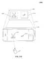
- FIG. 6is one implementation of a motion sensory control device that detects gestures in a three dimensional (3D) sensory space.
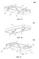
- FIG. 7Ais a perspective view from the top of a motion sensory control device in accordance with the technology disclosed, with motion sensors along an edge surface thereof.
- FIG. 7Bis a perspective view from the bottom of a motion sensory control device in accordance with the technology disclosed, with motion sensors along the bottom surface thereof.
- FIG. 7Cis a perspective view from the top of a motion sensory control device in accordance with the technology disclosed, with detachable motion sensors configured for placement on a surface.
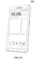
- FIG. 8Aillustrates one implementation of a smart phone equipped with a motion sensory control device.
- FIG. 8Billustrates one implementation of a motion sensory control device embedded in a swivel camera of a smart phone.
- FIG. 8Cillustrates one implementation of a motion sensory control device embedded in a mobile case of a smart phone.
- FIG. 8Dillustrates one implementation of a motion sensory control device embedded in a portrait mobile case of a smart phone.
- FIG. 8Eillustrates one implementation of a motion sensory control device embedded in a landscape mobile case of a smart phone.
- FIG. 8Fillustrates one implementation of a motion sensory control device embedded in a keyboard-less tablet case of a computer tablet.
- FIG. 8Gillustrates one implementation of a motion sensory control device embedded in a tablet case of a computer tablet.
- FIG. 9illustrates one implementation of a motion sensory control device peripherally connected to a smart phone.
- FIG. 10is one implementation of switching a smart phone to a hand-held mode of operation when the embedded motion sensory control device is upright and moving.
- FIG. 11shows one implementation of switching a smart phone to a wide-area mode of operation when the embedded motion sensory control device is laid flat and stationary.
- FIG. 12Adepicts one implementation of switching a smart phone to an across-the-room mode of operation.
- FIG. 12Bdepicts the basic operations and functional units involved in motion capture and image analysis in accordance with implementations of the technology disclosed.
- FIG. 12Cis a characterization of an ellipse into different parameters across a xy plane.
- FIG. 13illustrates one implementation of switching a smart phone to a pairing mode of operation.
- FIG. 14Aillustrates a system for capturing image data according to one implementation of the technology disclosed.
- FIG. 14Billustrates apparent movement of objects from the perspective of a surveillance viewer of an environment in accordance with the technology disclosed.
- FIG. 15illustrates apparent movement of objects from the perspective of a user of a virtual environment enabled apparatus in accordance with the technology disclosed.
- FIG. 16shows one implementation of broadcasting device identity tokens from a plurality of heterogeneous appliances over an ultra-short-range communication channel in a pervasive computing environment.
- FIG. 17illustrates one implementation of selection-by-pointing technique in a pervasive computing environment.
- FIG. 18shows one implementation of selecting a device from a plurality of devices in a pervasive computing environment based on level of proximity of the devices.
- FIG. 19depicts one implementation of selecting a device from a plurality of devices in a pervasive computing environment based on positional information of the devices.
- FIG. 20illustrates one implementation of gesturally interacting with devices that lack gestural responsiveness.
- FIGS. 21A, 21B, and 21Cshow one implementation of distinguishing between users issuing gestural commands in a pervasive three dimensional (3D) sensory environment.
- FIG. 22is one implementation of selecting among virtual interaction modalities to interact with in a pervasive augmented environment.
- FIGS. 23A, 23B, 23C, 23D, and 23Eillustrate one implementation of interacting with marker images that trigger augmented illusions in a pervasive virtual environment.
- FIG. 24is one implementation of a platform providing abstract feature information to an application.
- a given signal, event or valueis “based on” a predecessor signal, event or value of the predecessor signal, event or value influenced by the given signal, event or value. If there is an intervening processing element, step or time period, the given signal, event or value can still be “based on” the predecessor signal, event or value. If the intervening processing element or step combines more than one signal, event or value, the signal output of the processing element or step is considered “based on” each of the signal, event or value inputs. If the given signal, event or value is the same as the predecessor signal, event or value, this is merely a degenerate case in which the given signal, event or value is still considered to be “based on” the predecessor signal, event or value. “Responsiveness” or “dependency” of a given signal, event or value upon another signal, event or value is defined similarly.
- the “identification” of an item of informationdoes not necessarily require the direct specification of that item of information.
- Informationcan be “identified” in a field by simply referring to the actual information through one or more layers of indirection, or by identifying one or more items of different information which are together sufficient to determine the actual item of information.
- the term “specify”is used herein to mean the same as “identify.”
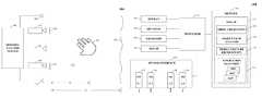
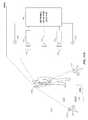
- FIG. 1Awhich illustrates an exemplary gesture-recognition system 100 A including any number of cameras 102 , 104 coupled to a sensory-analysis system 106 .
- Cameras 102 , 104can be any type of camera, including cameras sensitive across the visible spectrum or, more typically, with enhanced sensitivity to a confined wavelength band (e.g., the infrared (IR) or ultraviolet bands); more generally, the term “camera” herein refers to any device (or combination of devices) capable of capturing an image of an object and representing that image in the form of digital data. While illustrated using an example of a two camera implementation, other implementations are readily achievable using different numbers of cameras or non-camera light sensitive image sensors (e.g. 118 ) or combinations thereof.
- IRinfrared
- lightis used generally to connote any electromagnetic radiation, which may or may not be within the visible spectrum, and may be broadband (e.g., white light) or narrowband (e.g., a single wavelength or narrow band of wavelengths).
- Cameras 102 , 104are preferably capable of capturing video images (i.e., successive image frames at a constant rate of at least 15 frames per second); although no particular frame rate is required.
- the capabilities of cameras 102 , 104are not critical to the technology disclosed, and the cameras can vary as to frame rate, image resolution (e.g., pixels per image), color or intensity resolution (e.g., number of bits of intensity data per pixel), focal length of lenses, depth of field, etc.
- image resolutione.g., pixels per image
- color or intensity resolutione.g., number of bits of intensity data per pixel
- focal length of lensese.g., depth of field, etc.
- any cameras capable of focusing on objects within a spatial volume of interestcan be used.
- the volume of interestcan be defined as a cube approximately one meter on a side.
- the illustrated gesture-recognition system 100 Aincludes one or more sources 108 , 110 , which can be disposed to either side of cameras 102 , 104 , and are controlled by sensory-analysis system 106 .
- the sources 108 , 110are light sources.
- the light sourcescan be infrared light sources, e.g., infrared light-emitting diodes (LEDs), and cameras 102 , 104 can be sensitive to infrared light.
- LEDsinfrared light-emitting diodes
- Use of infrared lightcan allow the gesture-recognition system 100 A to operate under a broad range of lighting conditions and can avoid various inconveniences or distractions that may be associated with directing visible light into the region where the person is moving.
- filters 120 , 122are placed in front of cameras 102 , 104 to filter out visible light so that only infrared light is registered in the images captured by cameras 102 , 104 .
- the sources 108 , 110are sonic sources providing sonic energy appropriate to one or more sonic sensors (not shown in FIG. 1A for clarity sake) used in conjunction with, or instead of, cameras 102 , 104 .
- the sonic sourcestransmit sound waves to the user; the user either blocks (or “sonic shadowing”) or alters the sound waves (or “sonic deflections”) that impinge upon her.
- Such sonic shadows and/or deflectionscan also be used to detect the user's gestures and/or provide presence information and/or distance information using ranging techniques known in the art.
- the sound wavesare, for example, ultrasound, that are not audible to humans.
- FIG. 1Ais representative and not limiting.
- lasers or other light sourcescan be used instead of LEDs.
- additional opticse.g., a lens or diffuser
- Useful arrangementscan also include short- and wide-angle illuminators for different ranges.
- Light sourcesare typically diffuse rather than specular point sources; for example, packaged LEDs with light-spreading encapsulation are suitable.
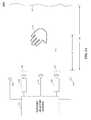
- light sources 108 , 110are arranged to illuminate a region of interest 112 that includes a control object such as hand 114 that can optionally hold a tool or other object of interest and cameras 102 , 104 are oriented toward the region of interest 112 to capture video images of the hand 114 with background 116 .
- the operation of light sources 108 , 110 and cameras 102 , 104is controlled by the sensory-analysis system 106 , which can be, e.g., a computer system, control logic implemented in hardware and/or software or combinations thereof. Based on the captured images, sensory-analysis system 106 determines the position and/or motion of an object of interest such as hand 114 .
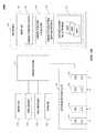
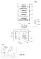
- FIG. 1Bis a simplified block diagram of a computer system 100 B, implementing sensory-analysis system 106 (also referred to as an image analyzer) according to an implementation of the technology disclosed.
- Sensory-analysis system 106can include or consist of any device or device component that is capable of capturing and processing image data.
- computer system 100 Bincludes a processor 132 , memory 134 , a sensor interface 136 , a display 138 (or other presentation mechanism(s), e.g. holographic projection systems, wearable goggles or other head mounted devices (HMDs), heads up displays (HUDs), other visual presentation mechanisms or combinations thereof, speakers 139 , a keyboard 140 , and a mouse 141 .
- HMDshead mounted devices
- HUDsheads up displays
- Memory 134can be used to store instructions to be executed by processor 132 as well as input and/or output data associated with execution of the instructions.
- memory 134contains instructions, conceptually illustrated as a group of modules described in greater detail below that control the operation of processor 132 and its interaction with other hardware components.
- An operating systemdirects the execution of low-level, basic system functions such as memory allocation, file management, and operation of mass storage devices.
- the operating systemcan include a variety of operating systems such as the Microsoft WINDOWS operating system, the Unix operating system, the Linux operating system, the Xenix operating system, the IBM AIX operating system, the Hewlett Packard UX operating system, the Novell NETWARE operating system, the Sun Microsystems SOLARIS operating system, the OS/2 operating system, the BeOS operating system, the MAC OS operating system, the APACHE operating system, the OPENACTION operating system, iOS, Android or other mobile operating systems, or another operating system platform.
- operating systemssuch as the Microsoft WINDOWS operating system, the Unix operating system, the Linux operating system, the Xenix operating system, the IBM AIX operating system, the Hewlett Packard UX operating system, the Novell NETWARE operating system, the Sun Microsystems SOLARIS operating system, the OS/2 operating system, the BeOS operating system, the MAC OS operating system, the APACHE operating system, the OPENACTION operating system, iOS, Android or other mobile operating systems, or another operating system platform.
- the computing environment 100 Bcan also include other removable/non-removable, volatile/nonvolatile computer storage media.
- a hard disk drivecan read or write to non-removable, nonvolatile magnetic media.
- a magnetic disk drivecan read from or write to a removable, nonvolatile magnetic disk
- an optical disk drivecan read from or write to a removable, nonvolatile optical disk such as a CD-ROM or other optical media.
- Other removable/non-removable, volatile/nonvolatile computer storage mediathat can be used in the exemplary operating environment include, but are not limited to, magnetic tape cassettes, flash memory cards, digital versatile disks, digital video tape, solid state RAM, solid state ROM, and the like.
- the storage mediaare typically connected to the system bus through a removable or non-removable memory interface.
- Processor 132can be a general-purpose microprocessor, but depending on implementation can alternatively be a microcontroller, peripheral integrated circuit element, a CSIC (customer-specific integrated circuit), an ASIC (application-specific integrated circuit), a logic circuit, a digital signal processor, a programmable logic device such as an FPGA (field-programmable gate array), a PLD (programmable logic device), a PLA (programmable logic array), an RFID processor, smart chip, or any other device or arrangement of devices that is capable of implementing the actions of the processes of the technology disclosed.
- a programmable logic devicesuch as an FPGA (field-programmable gate array), a PLD (programmable logic device), a PLA (programmable logic array), an RFID processor, smart chip, or any other device or arrangement of devices that is capable of implementing the actions of the processes of the technology disclosed.
- Sensor interface 136can include hardware and/or software that enables communication between computer system 100 B and cameras such as cameras 102 , 104 shown in FIG. 1A , as well as associated light sources such as light sources 108 , 110 of FIG. 1A .
- sensor interface 136can include one or more data ports 146 , 148 to which cameras can be connected, as well as hardware and/or software signal processors that modify data signals received from the cameras (e.g., to reduce noise or reformat data) prior to providing the signals as inputs to a motion-capture (“mocap”) program 144 executing on processor 132 .
- micapmotion-capture
- sensor interface 136can also transmit signals to the cameras, e.g., to activate or deactivate the cameras, to control camera settings (frame rate, image quality, sensitivity, etc.), or the like. Such signals can be transmitted, e.g., in response to control signals from processor 132 , which can in turn be generated in response to user input or other detected events.
- Sensor interface 136can also include controllers 147 , 149 , to which light sources (e.g., light sources 108 , 110 ) can be connected.
- controllers 147 , 149provide operating current to the light sources, e.g., in response to instructions from processor 132 executing mocap program 144 .
- the light sourcescan draw operating current from an external power supply, and controllers 147 , 149 can generate control signals for the light sources, e.g., instructing the light sources to be turned on or off or changing the brightness.
- a single controllercan be used to control multiple light sources.
- mocap program 144Instructions defining mocap program 144 are stored in memory 134 , and these instructions, when executed, perform motion-capture analysis on images supplied from cameras connected to sensor interface 136 .
- mocap program 144includes various modules, such as an object detection module 152 , an object/path analysis module 154 , and an object/gesture-recognition module 156 .
- Object detection module 152can analyze images (e.g., images captured via sensor interface 136 ) to detect edges of an object therein and/or other information about the object's location.
- Object/path analysis module 154can analyze the object information provided by object detection module 152 to determine a 3D position and/or motion of the object (e.g., a user's hand 114 ).
- Memory 134can also include other information and/or code modules used by mocap program 144 such as an application platform 158 that allows a user to interact with the mocap program 144 using different applications like application 1 (App1), application 2 (App2), and application N (AppN).
- application 1App1
- App2application 2
- AppNapplication N
- Display 138 , speakers 139 , keyboard 140 , and mouse 141can be used to facilitate user interaction with computer system 100 B.
- results of gesture capture using sensor interface 136 and mocap program 144can be interpreted as user input.
- a usercan perform hand gestures that are analyzed using mocap program 144 , and the results of this analysis can be interpreted as an instruction to some other program executing on processor 132 (e.g., a web browser, word processor, or other application).
- processor 132e.g., a web browser, word processor, or other application.
- a usermight use upward or downward swiping gestures to “scroll” a webpage currently displayed on display 138 , or use rotating gestures to increase or decrease the volume of audio output from speakers 139 , and so on.
- Computer system 100 Bis illustrative and that variations and modifications are possible.
- Computer systemscan be implemented in a variety of form factors, including server systems, desktop systems, laptop systems, tablets, smart phones or personal digital assistants, wearable devices, e.g., googles, head mounted devices (HMDs), wrist computers, and so on.
- a particular implementationcan include other functionality not described herein, e.g., wired and/or wireless network interfaces, media playing, and/or recording capability, etc.
- one or more camerascan be built into the computer or other device into which the sensor is imbedded rather than being supplied as separate components.
- an image analyzercan be implemented using only a subset of computer system components (e.g., as a processor executing program code, an ASIC, or a fixed-function digital signal processor, with suitable I/O interfaces to receive image data and output analysis results).
- computer system componentse.g., as a processor executing program code, an ASIC, or a fixed-function digital signal processor, with suitable I/O interfaces to receive image data and output analysis results.
- the userperforms a gesture that is captured by cameras 102 , 104 as a series of temporally sequential images.
- cameras 102 , 104can capture any observable pose or portion of a user. For instance, if a user walks into the field of view near the cameras 102 , 104 , cameras 102 , 104 can capture not only the whole body of the user, but the positions of arms and legs relative to the person's core or trunk. These are analyzed by the object/gesture-recognition module 156 , which can be implemented as another module of the mocap 144 .
- object/gesture-recognition module 156provides input to an electronic device, allowing a user to remotely control the electronic device, and/or manipulate virtual objects, such as prototypes/models, blocks, spheres, or other shapes, buttons, levers, or other controls, in a virtual environment displayed on display 138 .
- virtual objectssuch as prototypes/models, blocks, spheres, or other shapes, buttons, levers, or other controls
- the usercan perform the gesture using any part of her body, such as a finger, a hand, or an arm.
- the sensory-analysis system 106can determine the shapes and positions of user's hand in 3D space and in real time; see, e.g., U.S. Ser. Nos.
- the sensory-analysis system 106can not only recognize gestures for purposes of providing input to the electronic device, but can also capture the position and shape of user's hand in consecutive video images in order to characterize the hand gesture in 3D space and reproduce it on display 138 .
- the object/gesture-recognition module 156compares the detected gesture to a library of gestures electronically stored as records in a database, which is implemented in the sensory-analysis system 106 , the electronic device, or on an external storage system.
- a databasewhich is implemented in the sensory-analysis system 106 , the electronic device, or on an external storage system.
- gesturescan be stored as vectors, i.e., mathematically specified spatial trajectories, and the gesture record can have a field specifying the relevant part of the user's body making the gesture; thus, similar trajectories executed by a user's hand and head can be stored in the database as different gestures so that an application can interpret them differently.
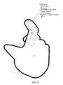
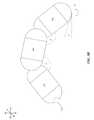
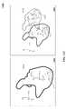
- FIGS. 2A, 2B, 2C, and 2Dillustrate one implementation of capsule representation of predictive information.
- FIG. 2Ais a simplified illustration of prediction information for an object according to an implementation.
- prediction information 20 of a control object 114 of FIG. 1Acan be constructed from one or more model subcomponents 30 , 32 , 34 selected and/or configured to represent at least a portion of a surface of control object 114 , one or more attributes 40 , and virtual surface portion 22 .
- Other componentscan be included in prediction information 20 , not shown in FIG. 2A for clarity sake.
- the model subcomponentscan be selected from a set of radial solids, which can reflect at least a portion of the control object 114 in terms of one or more of structure, motion characteristics, conformational characteristics, other types of characteristics of control object 114 , and/or combinations thereof.
- radial solidsare objects made up of a 2D primitive (e.g., line, curve, plane) and a surface having a constant radial distance to the 2D primitive. A closest point to the radial solid can be computed relatively quickly. As used herein, three or greater capsules are referred to as a “capsoodle”.
- One radial solid implementationincludes a contour and a surface defined by a set of points having a fixed distance from the closest corresponding point on the contour.
- Another radial solid implementationincludes a set of points normal to points on a contour and a fixed distance therefrom.
- computational technique(s) for defining the radial solidinclude finding a closest point on the contour and the arbitrary point, then projecting outward the length of the radius of the solid. In an implementation, such projection can be a vector normal to the contour at the closest point.
- An example radial solid(e.g., 32 , 34 ) includes a “capsuloid”, i.e., a capsule shaped solid including a cylindrical body and semi-spherical ends.
- Another type of radial solid(e.g., 30 ) includes a sphere. Other types of radial solids can be identified based on the foregoing teachings.
- One or more attributes 40can define characteristics of a model subcomponent 32 . Attributes can include e.g., sizes, rigidity, flexibility, torsion, zero or more degrees of freedom of motion with respect to one or more defined points, which can include endpoints for example.
- predictive information about the control objectcan be formed to include a model of the control object 114 together with attributes defining the model and values of those attributes.
- control object 114when control object 114 morphs, conforms, and/or translates, motion information reflecting such motion(s) is included into the observed information.
- Points in spacecan be recomputed based on the new observation information.
- the model subcomponentscan be scaled, sized, selected, rotated, translated, moved, or otherwise re-ordered to enable portions of the model corresponding to the virtual surface(s) to conform within the set of points in space.
- a collection of radial solids and/or capsuloidscan be considered a “capsule hand”.
- a number of capsuloids 172e.g. five capsuloids, are used to represent fingers on a hand while a number of radial solids 174 are used to represent the shapes of the palm and wrist.
- a finger capsuloid with radial solids 182 , 184 , 186can be represented by its two joint angles ( ⁇ , ⁇ ), pitch ( ⁇ ), and yaw ( ⁇ ).
- the angle ⁇can be represented as a function of joint angle ⁇ , pitch ⁇ , and yaw ⁇ .
- one capsule handcan include five capsules for each finger, a radial polygon defining a base of a hand and a plurality of definitional capsules that define fleshy portions of the hand.
- analyzingincludes stereo matching, depth maps, finding contours and/or feature points reduced to certain finite number of degrees of freedom. Such an analysis enables simplification of problems of IK, sampling sizes, pose determination, etc.
- FIGS. 3A, 3B, 3C, 3D, 3E, 3F, 3G, and 3Hillustrate one implementation of initializing capsule representation of predictive information.
- Initializationcan include determining and applying one or more initialization parameters to the model to scale and orient the model.
- initializationincludes scaling a model by an appropriate initialization parameter.
- FIG. 3Adepicts determining spans and span lengths in the observed information in which one or more point pairings are selected from a surface portion as represented in the observed information.
- an observed surface portion 201i.e., of observed information
- a point pairing between point A and point B of observed surface portion 201is selected by application of a matching function, such as for example the matching function.
- a matching functionsuch as for example the matching function.
- a first unmatched (arbitrary) point A on a contour (of block 22 of FIG. 3A ) representing a surface portion of interest in the observed informationis selected as a starting point 202 .
- a normal A 1 203(of block 22 of FIG. 3A ) is determined for point A.
- Another techniquecan be to: (i) start with the set of points; (ii) form a first vector from P 2 ⁇ P 1 ; and (iii) apply rotation matrix to rotate the first vector 90 degrees away from the center of mass of the set of points. (The center of mass of the set of points can be determined by an average of the points).
- a yet further techniquecan be to: (i) determine a first vector tangent to a point on a contour in a first image; (ii) determine from the point on the contour a second vector from that point to a virtual camera object in space; and (iii) determine a cross product of the first vector and the second vector. The cross product is a normal vector to the contour.
- the closest second unmatched point B 204(of block 22 of FIG. 3A ) reachable by a convex curve (line 206 ) and having the most opposite normal B 1 205 is found. Accordingly, points A and B form a point pairing. As illustrated by block 26 of FIG. 3A , the object need not be a hand (nor for that matter, even a portion of a human being).
- a span lengthis determined for at least one of the one or more point pairings selected.
- one or more spans and span lengthsare determined for the one or more point pairings.
- a spancan be found by determining a shortest convex curve for the point pairings A and B. It is determined whether the convex curve passes through any other points of the model. If so, then another convex curve 206 is determined for paired points A and B. Otherwise, the span comprises the shortest continuous segment found through paired points A and B that only intersects the model surface at paired points A and B.
- the spancan comprise a convex geodesic segment that only intersects the model at two points.
- a spancan be determined from any two points using the equation of a line fitted to the paired points A and B for example.
- Block 28shows fitting of one or more radial basis functions 208 - 1 , 208 - 2 , and 208 - 3 to the observed span lengths L1, L2 and L3.
- a radial basis function(Gaussian or approximation thereof) can be selected for one or more observed span length values using techniques described below.
- a function appropriate to the implementationis applied to the radial basis functions to provide a frequency of occurrence for the span lengths.
- the radial basis functions 208 - 1 , 208 - 2 , and 208 - 3are summed to arrive at a frequency of occurrence wave 210 for the observed span lengths.
- other functionsmultiplication, averaging, interpolation, and so forth, and/or combinations thereof depending upon the implementation specific requirements or desirability
- smoothing techniquesinterpolation, Gaussian, bucketing, rounding, others, combinations thereof
- Parameters for the radial basis functionscan be selected using a variety of techniques.
- One technique for determining a width of a radial basis functionincludes selecting a radial basis function for one or more observed span length values, having one or more properties, which can be determined. For example, a variance of the dataset including the observed span lengths is determined. The variance is divided by an expectation value. Expectation values can be determined from an expected number of modes in the dataset determined from the span lengths in the observed information. For example, using horizontally disposed spans, as illustrated by FIG.
- observed span lengths of a hand and armcan be sorted into approximately four expected expectation values: one value corresponding to an approximate cross finger diameter length; one value corresponding to a cross the palm length; one value corresponding to a span across the palm to the thumb; and one value corresponding to a span cross the wrist length.
- a facecan be sorted into one value.
- An automobileobserved from its side
- the variance divided by the expectation valueis provided as a width of the radial basis function.
- Other techniques for determining frequencies of occurrence for the various span lengthsinclude bucketing—in which buckets of fixed or variable width are assigned to one or more discrete points representing span length occurrences within some range corresponding to the bucket width.
- the frequency of occurrences for each bucketcan be combined (e.g., interpolation, summed, weighted, smoothed or other combinations, and/or combinations thereof) to produce a frequency of occurrence function.
- a span lengthcan be selected as the initialization parameter based upon the frequency of occurrences of observed span lengths.
- an initialization parametercan be determined using a technique for performing mode selection on the frequencies of occurrence for the bucketed span lengths.
- mode selectionillustrated with reference to FIG. 3B , that includes determining one or more modes from the frequencies of occurrence of observed span lengths.
- mode 1 ( 212 - 1 ) and mode 2 ( 212 - 2 )are defined by locations on the frequency occurrence wave 210 in which there exists a local minima or maxima.
- one technique for determining modes from the frequencies of occurrencecomprises finding minima or maxima of the frequency of occurrence wave 210 .
- a mode of intereste.g., a mode having a most frequently occurring span length, can be selected.
- One technique for determining minima or maxima indicating modescomprises employing a gradient descent technique.
- a gradientcan be determined (i.e., by taking a derivative 214 of a function representing a frequency of occurrence (for example frequency occurrence wave 210 determined above)).
- One or more minima 214 b of the derivative 214 of the functioncan be determined to indicate a mode of interest.
- one techniqueapplies Rolle's Theorem to determine a minima (or maxima) at a point in the frequency occurrence wave 210 along some closed interval demarcated by two points on the curve having the same function value.
- An initialization parameteris determined from the mode of interest. For example, again with reference to block 29 of FIG. 3B , a span length L 1 corresponding to mode 1 ( 212 - 1 ) is selected as the initialization parameter.
- properties of the frequency of occurrence other than modecan be used to determine an initialization parameter. For example, expected value of frequency of occurrence, appearance of the number of modes, spacing between modes, other properties, and/or combinations thereof can be used to determine initialization parameters. Accordingly, a most frequently occurring span length can be used as an initialization parameter. In an alternative implementation, a least frequently occurring span length (L 2 in block 28 of FIG. 3B ) can be returned as the initialization parameter.
- an initialization parameteris applied to at least a portion of a model within the predictive information.
- Application of the initialization parametercan be used to initialize the model portion using a variety of techniques—scaling, weighting, specifying (or computing) confidence factors, selecting model portions, and mode selection (child's hand, cat's paw, tool tip, and so forth).
- span length(s) of one or more portion of a model 302 in the predictive informationcan be scaled using the initialization parameter L 1 as a scaling factor to produce an initialized model 304 .
- scalingcan include multiplying (or dividing) the span length(s) by the scaling factor.
- the scaling factorcan be applied according to a function based on the scaling factor, for example, a function F(L 1 ) that determines based at least in part upon the initialization parameter that a model portion is too large (or small) and can be used to exclude (or alter the weighting or confidence factor) for that portion in the model.
- the span length(s)can be scaled according to the scaling factor and one or more quantifiable characteristics can be determined from imaging the object (i.e., brightness, frequencies, and so forth).
- a model portionis selected based at least in part upon the initialization parameter.
- an initialization parametercan be used to select from models of adult hands, children's hands, animal paws, tool tips, and so forth.
- initialization parameterscan be used to communicate control information to the sensory device, for example, changing power consumption profiles based on size of observed object(s), changing frame rates, selecting user modes in software (tool, hand, face discrimination), background elimination, noise elimination; see, e.g., U.S. Ser. No. 61/911,975, filed Dec. 4, 2013.
- initializationincludes orienting a model by an appropriate initialization parameter.
- FIG. 3Dillustrates one or more contours that are extracted from a surface portion as represented in the observed information.
- a surface portion of an imaged object 200e.g., image of real object(s), computer generated input, or combinations thereof
- a surface portion of an imaged object 200within the observed information can comprise a plurality of surfaces that can be sampled to provide points 201 , from which one or more contours 202 can be extracted.
- the observed informationcan be sampled to determine a set of points.
- the observed informationcan comprise an image or images of the imaged object 200 to be sampled.
- the observed informationcomprises instead of, a set of points or a set of contours determined from an imaged object 200 .
- one or more contours 202can be determined using any of a variety of techniques, such as for example determining a gradient for points determined from the imaged object. When a relatively larger value of the gradient is determined, points along the relatively larger value of the gradient can comprise a contour.
- a contour portion A 202can be determined from a plurality of points 201 of block 20 .
- one or more contour parametersare identified for at least one extracted contour.
- a contour parameter comprising normal A1 203can be determined from contour portion A 202 .
- a first (arbitrary) point P1 on a contour portion representing a surface portion of interest in the observed informationis selected as a starting point.
- a normalis identified at the point P1.
- One method of determining a normalis illustrated by block 22 of FIG. 3D , in which a set of points proximate to the first point P1, at least two of which are not co-linear, is determined.
- Another techniquecan be to: (i) start with the set of points; (ii) form a first vector from P2 ⁇ P1; and (iii) apply rotation matrix to rotate the first vector 90 degrees away from the center of mass of the set of points. (The center of mass of the set of points can be determined by an average of the points).
- a yet further techniquecan be to: (i) determine a first vector tangent to a point on a contour in a first image; (ii) determine from the point on the contour a second vector from that point to a virtual camera object in space; and (iii) determine a cross product of the first vector and the second vector. The cross product is a normal vector to the contour.
- other instances of the contour parameteri.e., other normal(s) can be determined for other contour portions determined from the sample points 201 corresponding to the imaged object 200 .
- instances of different types of contour parameterse.g., center(s) of mass, (e.g., a weighted average of the points within a set), a curvature(s), and so forth, can be determined for the contour portions determined from the sample points 201 corresponding to the imaged object 200 .
- One way to determine a contour propertyis illustrated by block 24 of FIG. 3D in which one or more contour parameters 203 are combined to produce a contour property 204 by applying a function.
- one or more normal(s) 203can be combined to form an average normal 204 .
- a function appropriate to the implementationis applied to the contour parameters to provide grouping of information from the contour parameters into a contour property.
- the average functioncan be applied to the set of normal(s) determined in block 22 to create an average normal 204 .
- An initialization parameteris determined based at least in part upon the at least one contour property determined above.
- An initialization parametercan be determined in a variety of ways, such as using one technique illustrated with reference to block 26 of FIG. 3E , in which a plane 210 ( FIG. 3E ) of best fit is determined through contours in the observed information.
- a number of techniquesare available for determining a plane of best fit illustrated with reference to block 26 of FIG. 3E , one example being multi-linear regression.
- a third vector 214is determined by combining a contour property 204 (e.g., average direction of plane normal vectors) with a normal vector 212 defining the plane 210 to derive a third vector 214 .
- One techniqueemploys a cross product to combine contour property 204 with normal vector 212 , however other techniques can be used in some implementations.
- An initialization parameter 220 determined from the three vectorsis provided to the system to initialize orientation of the model.
- normal vector 212 , contour property 204 , and cross product 214can be provided as the initialization parameter 220 .
- the procedurecompletes and returns a set of vectors as an initialization parameter.
- a least one of the vectors( 214 in block 26 of FIG. 3E ) can be returned as the initialization parameter 220 .
- Orientation of the model portionis initialized by applying the initialization parameter to at least a portion of a model within the predictive information.
- Application of the initialization parametercan be used to initialize orientation of the model portion using a variety of techniques—aligning, weighting, specifying (or computing) confidence factors, selecting model portions, and mode selection (child's hand, cat's paw, tool tip, and so forth).
- aligningcan include rotational alignment of the model along one or more axes to correspond to the initialization parameter.
- the rotational alignmentcan be applied to portion(s) of the model according to a function F, that determines, based at least in part upon the initialization parameter, that a model portion is too far removed from alignment in one or more directions for example to be used.
- Function Fcan exclude (or alter the weighting or confidence factor) for that portion in the model based at least in part upon the initialization parameter.
- the modelcan be aligned according to the initialization parameter and one or more quantifiable characteristics determined from imaging the object (i.e., brightness, frequencies, and so forth).
- a model portioncan be selected based at least in part upon a degree to which the model portion(s) align to the initialization parameter.
- an initialization parametercan be used to select from models for adult hands, children's hands, animal paws, tool tips, and so forth based upon alignment.
- initialization parameterscan be used to communicate control information to the sensory device, for example, changing power consumption profiles based on quality of alignment of observed object(s), changing frame rates, selecting user modes in software (tool, hand, face discrimination), background elimination, noise elimination.
- a compensationcan be applied to a model within the observed information.
- one of a variety of techniques for fitting models to observed information in which one or more elements is missing, either due to differences in the object being observed and/or the viewing environment (e.g., noise, occlusions, poor contrast, and so forth)comprises fitting model portion(s) to extremity portion(s) of an observed object and/or fitting model portion(s) to contour segments and properties.
- One technique for fitting a modelare illustrated by block 30 of FIG. 3F which includes determining observed extremities 303 , 305 of an object portion(s) 302 in the observed information corresponding to model extremities 313 , 315 in a default model 312 .
- a first quality of fitis determined between the observed information and the default model.
- a model compensation techniqueis applied to the default model 312 to form a compensated model 322 .
- the compensation techniqueis to curve a plurality of model extremities under the model because they are likely occluded in the observed information.
- a second quality of fitis determined between the observed information and the compensated model.
- a determinationis made whether the quality of fit to the compensated model is superior to the quality of fit to the default model. If so, the compensated model is adopted. Otherwise, in the event that the observed information fit the default model better than the compensated model, processing returns to try another compensation technique if available.
- more than one compensationcan be applied to the model to refine the model for various different occlusions, or the like.
- a fingertip positioncan be determined from the image and reconstructed in 3D as illustrated.
- a point 370is an observed fingertip.
- Model capsules 182 , 184 , 186are aligned such that the tip of capsule 182 is coincident with the location in space of point 370 determined from the observed information.
- angle ⁇ and angle ⁇are allowed to be set equal, which enables a closed form solution for ⁇ and ⁇ as well as angle ⁇ and angle ⁇ .
- norm(x)is described as the norm of a 3D point x ( 370 in FIG. 3G ) and a, b and c are capsule lengths L 182 , L 184 , L 186 in FIG. 3G .
- FIG. 4illustrates one implementation of improving capsule representation of predictive information.
- observation information 422 including observation of the control objectcan be compared against the model at one or more of periodically, randomly or substantially continuously (i.e., in real time).
- Observational information 422can include, without limitation, observed values of attributes of the control object corresponding to the attributes of one or more model subcomponents in the predictive information for the control object.
- comparison of the model 424 with the observation information 422provides an error indication 426 (also referred to as “variance”).
- an error indication 426can be computed by first associating a set A of three dimensional points with a corresponding normal direction 432 to a set B of three dimensional points with a corresponding normal direction 434 on the subcomponents surface. The association is done in a manner that assures that each paired point in set A and B has the same associated normal. An error can then be computed by summing the distances between each point in set A and B. This error is here on referred to the association error; see, e.g., U.S. Ser. No. 61/873,758, filed Sep. 4, 2013.
- Predictive information of the modelcan be aligned to the observed information using any of a variety of techniques. Aligning techniques bring model portions (e.g., capsules, capsuloids, capsoodles) into alignment with the information from the image source (e.g., edge samples, edge rays, interior points, 3D depth maps, and so forth).
- the modelis rigidly aligned to the observed information using iterative closest point (ICP) technique.
- ICPiterative closest point
- the modelcan be non-rigidly aligned to the observed information by sampling techniques.
- An optimal R and Tare computed and applied to the set of points A or B, according to some implementations.
- a capsule matching techniqueis employed.
- One implementation of the capsule matchingincludes a class that “grabs” the set of data and computes the closest point on each tracked hand (using information like the normal). Then, the minimum of those closest points is associated to the corresponding hand and saved in a structure called Hand Data. Other points that don't meet a minimal distance threshold are marked as unmatched.
- rigid transformations and/or non-rigid transformationscan be composed.
- One example composition implementationincludes applying a rigid transformation to predictive information. Then an error indication can be determined, and an error minimization technique such as described herein can be applied.
- determining a transformationcan include calculating a rotation matrix that provides a reduced RMSD (root mean squared deviation) between two paired sets of points.
- RMSDroot mean squared deviation
- the transformation(both R and T) are applied rigidly to the model.
- the capsule matching and rigid alignmentis repeated until convergence is achieved between model 424 with observation information 422 .
- the Kabschis extended to ray or covariances by minimizing the error using the following formula: ⁇ ( R*xi+T ⁇ yi ) t*Mi *( R*xi+T ⁇ yi )
- M iis a positive definite symmetric matrix.
- one or more force linescan be determined from one or more portions of a virtual surface.
- a fingeris represented by a 3D vector where the entry of each vector is a pitch, yaw and bend of the finger.
- the Pitch and Yawcan be defined trivially.
- the bendis the angle between the first and second capsule and the second and third capsule which are set to be equal.
- the mean of the samples weighted by the RMSis taken to be the new finger parameter, according to one implementation.
- predictive informationcan include collision information concerning two or more capsoloids.
- collision informationconcerning two or more capsoloids.
- a relationship between neighboring capsoloids, each having one or more attributescan be determined.
- determining a relationship between a first capsoloid having a first set of attributes and a second capsoloid having a second set of attributesincludes detecting and resolving conflicts between first attribute and second attributes.
- a conflictcan include a capsoloid having one type of angle value with a neighbor having a second type of angle value incompatible with the first type of angle value. Attempts to attach a capsoloid with a neighboring capsoloid having attributes such that the combination will exceed what is allowed in the observed—or to pair incompatible angles, lengths, shapes, or other such attributes—can be removed from the predicted information without further consideration.
- raw image information and fast lookup tablecan be used to find a look up region that gives constant time of computation of the closest point on the contour.
- Fingertip positionsare used to compute point(s) on the contour which can be then used to determine whether the finger is extended or non-extended.
- a signed distance functioncan be used to determine whether points lie outside or inside a hand region. An implementation checks to see if points are inside or outside the hand region.
- informationcan be abstracted from the model. For example, velocities of a portion of a hand (e.g., velocity of one or more fingers, and a relative motion of a portion of the hand), state (e.g., position, an orientation, and a location of a portion of the hand), pose (e.g., whether one or more fingers are extended or non-extended, one or more angles of bend for one or more fingers, a direction to which one or more fingers point, a configuration indicating a pinch, a grab, an outside pinch, and a pointing finger), and whether a tool or object is present in the hand can be abstracted in various implementations.
- velocities of a portion of a hande.g., velocity of one or more fingers, and a relative motion of a portion of the hand
- statee.g., position, an orientation, and a location of a portion of the hand
- posee.g., whether one or more fingers are extended or non-extended, one or more angles
- a method of providing command input to a machine under control by tracking hands (or other body portions, alone or in conjunction with tools) using a sensory machine control systemincludes capturing sensory information for a human body portion within a field of interest.
- a tracking model and biometric modelare determined from the sensory information by analyzing images, alone or in conjunction with non-imaging sensory information, to yield 3D information suitable for defining a capsule model of the subject being imaged.
- the 3D informationis associated to one or more capsules in a model.
- the capsule modelis aligned (rigidly, non-rigidly, or combinations thereof) with the 3D information.
- Information from the modelis abstracted to detect a variance and/or a state of the subject being imaged.
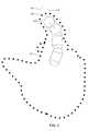
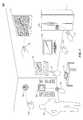
- FIG. 5shows one implementation of a pervasive computing environment 500 in which a machine sensory device might be used.
- pervasive computing environment 500can include various home automation systems such as lighting systems, in-home monitoring systems, security systems, appliance systems, VoIP phone systems, other phone systems, other home automation systems, or any combination thereof.
- smart phone 516 equipped with a motion sensory control deviceis adapted to control each of the home automation systems, including but not limited to entertainment unit 506 , thermostat and HVAC control 504 , laptop computer 508 , desktop computer 510 , television 512 , and refrigerator 514 .
- smart phone 516can include one or more sensors to, e.g., detect acceleration, temperature, humidity, water, supplied power, proximity, external motion, device motion, sound signals, ultrasound signals, light signals, fire, smoke, carbon monoxide, global-positioning-satellite (GPS) signals, radio-frequency (RF), WiFi, or other electromagnetic signals or fields.
- smart phone 516can include temperature sensor(s), humidity sensor(s), hazard-related sensor(s) or other environmental sensor(s), accelerometer(s), microphone(s), optical sensors up to and including camera(s) (e.g., charged-coupled-device or video cameras), active or passive radiation sensors, GPS receiver(s) or radio-frequency identification detector(s). While FIG.
- smart phone 516includes one or more primary sensors and one or more secondary sensors.
- the primary sensor(s)can sense data central to the core operation of the device (e.g., interpreting gestures performed in the environment 500 ).
- the secondary sensor(s)can sense other types of data (e.g., light, acceleration, or sound).
- one or more user-interface components 138 in smart phone 516can be used to present information to a user 502 via a visual display (e.g., a thin-film-transistor display or organic light-emitting-diode display) and/or an audio speaker.
- user-interface components 138can receive information from the user 502 through a touchscreen, buttons, scroll component (e.g., a movable or virtual ring component), microphone, and/or camera (e.g., to detect gestures).
- user 502can select a device from among the different devices in the environment 500 by performing a gesture and/or and other body movements.
- a gesture and/or and other body movementscan be used to select a device.
- pure gestures, or gestures in combination with voice recognition, and/or a virtual or real keyboard in combination with the gesturescan be used to select a device.
- a control console that recognizes gesturescan be used to control an entire home, school, university, factory floor, office or other place of business.
- user 502can raise an arm, utter a verbal command, perform an optical command, or make different poses using hands and fingers (e.g., ‘one finger point’, ‘one finger click’, ‘two finger point’, ‘two finger click’, ‘prone one finger point’, ‘prone one finger click’, ‘prone two finger point’, ‘prone two finger click’, ‘medial one finger point’, ‘medial two finger point’) to indicate an intent to interact with a particular device in the environment 500 .
- a point and grasp gesturecan be used to move a cursor on a display of a device in the environment 500
- verbal commandscan be used to select a function
- eye movementscan be used to move a cursor
- blinkingcan indicate a selection.
- the gesturescan control the different devices in environment 500 using a graphical display or other feedback device, a set of menu elements, selection elements, and pan and zoom capabilities. Navigation through the devices can be consistent from high-level selection of target device down to manipulation of individual selection elements.
- a pointing cursor and contextual menu elements for the current deviceare activated.
- the cursor positionis driven by the movement and/or aim of the index finger.
- Basic selection and control over button, slider, and menu elementsis accomplished by positioning the pointer within an element and moving the thumb to the down/click (aligned with index finger) position. Moving the cursor off the screen to the medial side brings up a high-level menu list, with cursor movement constrained to two dimensions (up and down). Selecting an option from the high-level menu acts to change devices (e.g., from the television to the refrigerator).
- the gestures or body movementscan also be used to switch a device on or off.
- user 502After selecting a device, user 502 performs a subsequent gesture such as a downward or upward swipe of hand and/or finger(s) to power on or off a device.
- a finger flip up or downcan be used to turn lights, television, or refrigerator on or off.
- ambient services performed using gestural interaction in environment 500can involve the filling of baths, pools and spas and the maintenance of a desired temperature in those facilities, as well as the control of any pumps associated with those facilities. They can also control individual devices and appliances such as kitchen appliances, exhaust fans, humidifiers, and dehumidifiers. In some implementations, they can control motorized devices such as skylights, draperies, furniture, walls, screens, ceilings, awnings, physical security barriers, door locks, and others. In other implementations, they can also control answering machines, voice mail systems, and provide maintenance reminders and perform functions such as telephone answering, controlling fountains or in-ground sprinkler systems, controlling kitchen and other appliances, controlling motorized drapes, windows and skylights, opening of locked doors and the scheduling of these functions.
- individual devices and appliancessuch as kitchen appliances, exhaust fans, humidifiers, and dehumidifiers.
- motorized devicessuch as skylights, draperies, furniture, walls, screens, ceilings, awnings, physical security barriers, door locks, and others.
- they
- these ambient servicescan be applied to other pervasive environments such as boats, aircraft, office suites, conference rooms, auditoriums, classrooms, theaters, hotels, hospitals, and retirement homes.
- one implementationincludes different paradigm-setting gestures ( 514 , 526 , 518 , 520 , 522 , 524 , 526 ) that set device-specific control paradigms to control responsiveness of various devices in a pervasive computing environment 500 . As shown in FIG.
- different gesturessuch as a grip-and-extend-again motion of two fingers of a hand, grip-and-extend-again motion of a finger of a hand, or holding a first finger down and extending a second finger can be used to determine a context for interpreting subsequent gestures and controlling a selected device.
- a vertical finger swipecan indicate a user intent to increase volume of a television or increase brightness of the television display.
- paradigm-setting gestures( 514 , 526 , 518 , 520 , 522 , 524 , 526 ) define how various gestures cause on-screen actions on the different devices and/or control their manual responsiveness.
- paradigm-setting gestures( 514 , 526 , 518 , 520 , 522 , 524 , 526 ) can define interaction modes to interact with different virtual screens or objects. For instance, when the user is interacting with a virtual newspaper active on a virtual screen, a forehand sweep can result in an increment change of an electronic page in the virtual newspaper, whereas the same gesture can result in collision of virtual cars in a virtual gaming environment generated by the same virtual screen.
- smart phone 516 equipped with a motion sensory control deviceis adapted to control each of the home automation systems, including but not limited to entertainment unit 506 , thermostat and HVAC control 504 , laptop computer 508 , desktop computer 510 , television 512 , and refrigerator 514 .
- FIG. 6is one implementation of a motion sensory control device 600 that detects gestures in a three dimensional (3D) sensory space.
- FIGS. 7A, 7B, and 7Cillustrate three different configurations of a motion sensory control device 700 , with reference to example implementations packaged within a single housing as an integrated sensor.
- motion sensory control device 700 A, 700 B, 700 Cincludes a top surface 705 , a bottom surface 707 , and a side wall 710 spanning the top and bottom surfaces 705 , 707 .
- FIG. 6is one implementation of a motion sensory control device 600 that detects gestures in a three dimensional (3D) sensory space.
- FIGS. 7A, 7B, and 7Cillustrate three different configurations of a motion sensory control device 700 , with reference to example implementations packaged within a single housing as an integrated sensor.
- motion sensory control device 700 A, 700 B, 700 Cincludes a top surface 705 , a bottom surface 707 , and a side wall 710 spanning the top and bottom surfaces
- the top surface 705 of motion sensory control device 700 Acontains a pair of windows 715 for admitting light to the cameras 102 , 104 , one of which is optically aligned with each of the windows 715 . If the system includes light sources 108 , 110 , surface 705 may contain additional windows for passing light to the object(s) being tracked.
- sources 108 , 110are located on the side wall 710 . Desirably, the motion sensors (not shown in the figure for clarity sake) are flush with the surface of side wall 710 so that, the motion sensors are disposed to sense motions about a longitudinal axis of motion sensory control device 700 A.
- the motion sensorscan be recessed from side wall 710 internal to the device in order to accommodate sensor operation and placement within available packaging space so long as coupling with the external housing of motion sensory control device 700 A remains adequate.
- sources 108 , 110are located proximate to the bottom surface 707 , once again in a flush or recessed configuration.
- the top surface of the motion sensory control device 700 B(not shown in the figure for clarity sake) contains camera windows 715 as shown in FIG. 7A .
- sources 108 , 110are external contact transducers that connect to motion sensory control device 700 C via jacks 720 . This configuration permits the motion sensors to be located away from the motion sensory control device 700 C, e.g., if the motion sensors are desirably spaced further apart than the packaging of motion sensory control device 700 C allows.
- FIG. 8Aillustrates one implementation of a smart phone 800 A equipped with a motion sensory control device.
- FIG. 8Billustrates one implementation of a motion sensory control device embedded in a swivel camera 800 B of a smart phone.
- FIG. 8Cillustrates one implementation 800 C of a motion sensory control device 812 embedded in a mobile case 814 of a smart phone 810 .
- FIG. 8Dillustrates one implementation 800 D of a motion sensory control device embedded 814 in a portrait mobile case 816 of a smart phone 810 .
- FIG. 8Eillustrates one implementation 800 E of a motion sensory control device 824 embedded in a landscape mobile case 822 of a smart phone 820 .
- FIG. 8Fillustrates one implementation 800 F of a motion sensory control device embedded 830 in a keyboard-less tablet case 828 of a computer tablet 826 .
- FIG. 8Gillustrates one implementation 800 G of a motion sensory control device 836 embedded in a tablet case 834 of a computer tablet 832 .
- FIG. 9illustrates one implementation 900 of a motion sensory control device 906 peripherally connected to a smart phone 902 through a data cable 904 .
- motion and sensory information collected by the motion sensory control device 906are transferred to the smart phone 902 thought the data cable 904 .
- gestures detected by the motion sensory control device 906are preprocessed to reduce required bandwidth and the preprocessed gestures are sent to the smart phone 902 via the communication channel.
- a motion-capture systemcaptures movement of a user, a portion of the user's body (often one or more of the user's hands) and/or object in three dimensional (“3D”) space using a computing device connected to one or more cameras. Once movement is captured, the computing device can interpret the movement as a user-input command and update a computer display accordingly.
- the computer displaycan illustrate a virtual representation of the user's hands and update that representation as the user moves his hands.
- the computer displaycan illustrate a virtual object that is manipulated (e.g., rotated or resized) as the user's hands move.
- FIG. 10is one implementation of switching a smart phone 1002 to a hand-held mode of operation 1000 when the embedded motion sensory control device is upright and moving.
- the smart phone 1002includes at least one of gyroscopes, accelerometers, tilt-sensors, and/or other such devices. These orientation and acceleration measuring devices when embed in the smart phone 1002 can generate one or more output signals like tri-axis signals for orthogonal x-, y-, and z-axes that indicate physical orientation of the smart phone 1002 .
- the motion sensory control device embedded in the smart phone 1002is switched to the hand-held mode of operation 1000 .
- FIG. 11shows one implementation of switching a smart phone to a wide-area mode of operation 1100 when the embedded motion sensory control device is laid flat and stationary.
- orientation and acceleration of the smart phone 1002can be measured using at least one of gyroscopes, accelerometers, tilt-sensors, and/or other such devices embedded in the smart phone 1002 and switch the smart phone 1002 to the wide-area mode of operation 1100 .
- FIG. 12Adepicts one implementation of switching a smart phone to an across-the-room mode 1200 A of operation.
- the smart phone 1296is in a wide-area mode of operation 1100 and its embedded motion sensory control device detects a gesture 1292 , the smart phone 1296 is switched to an across-the-room mode of operation.
- conserving power on a smart phone equipped with motion sensory control devicesincludes identifying a mode of operation of the smartphones.
- the mode of operationis “hand-held,” it is inferred that the user is in a telephonic conversation and does not intend to use the gesture recognition and interpretation capabilities of the embedded motion sensory control device.
- the recognition and interpretation capabilities of the embedded motion sensory control devicecan be lowered or de-activated to save power.
- the phoneis “wide-area” or “across-the-room” mode of operations, such capabilities can be increased or activated. This is achieved by adjusting one or more image acquisition parameters and/or image-analysis parameters embedded motion sensory control device.
- image acquisition parametersinclude frame resolution and frame capture rate and image-analysis parameters include analysis algorithm and analysis density.
- a “hand-held” mode of operationcan initiate the gesture recognition and interpretation capabilities along with an “anti-jittering” effect or “drift-compensation” mode as described later in this application.
- power to illumination sources incorporated with the motion sensory devicecan be tailored for long distance operation, e.g., illumination sources can be “strobed” (e.g., pulsed) to provide intense bursts of illumination over a shorter period of time, effectively providing greater illumination at reduced power consumption.
- operation of an embedded motion sensory control deviceis tailored and ideally tuned to one or more modes of operation of a smart phone.
- imagesare captured by one or more cameras of the smart phone and stored in “frame buffers”—i.e., partitions or dedicated segments of computer memory that store digital images as ordered arrays of image points or “pixels.”
- a motion sensory control devicecan include a set of image-analysis algorithms that locate, in an image, groups or regions of pixels that correspond to an object in the recorded scene—e.g., a user's moving hand.
- a digital imagehas a size (in pixels) and a resolution, and the image-analysis algorithm takes image input and processes it into an output defining objects in the image and their movements from image to image.
- a suitable (and ideally well suited) combination of parametersis selected, specifying, for example, characteristics of the images, their rate of acquisition and how the image-analysis algorithm processes them so that adequate overall performance is provided.
- FIG. 12Bdepicts the basic operations and functional units 1200 B involved in motion capture and image analysis in accordance with implementations of the technology disclosed.
- the camera(s) 1200record digital images 1210 of a scene. Each digital image is captured as an array of pixel values by the associated camera's image sensor, and the digital images are transferred—either in “raw” format or following conventional preprocessing—to one or more frame buffers 1205 .
- a frame bufferis a partition or dedicated segment of volatile memory that stores a “bitmapped” image frame 1220 corresponding to the pixel values of an image as output by the camera 1200 that recorded it.
- the bitmapis generally organized conceptually as a grid, with each pixel mapped one-to-one or otherwise to output elements of a display. It should be stressed, however, that the topology of how memory cells are physically organized within the frame buffers 1205 does not matter and need not conform directly to the conceptual organization.
- the number of frame buffers included in a systemgenerally reflects the number of images simultaneously analyzed by the analysis system or module 1230 , which is described in greater detail below.
- analysis module 1230analyzes the pixel data in each of a sequence of image frames 1220 to locate objects therein and track their movement over time (as indicated at 1240 ). This analysis can take various forms, and the algorithm performing the analysis dictates how pixels in the image frames 1220 are handled. For example, the algorithm implemented by analysis module 1230 can process the pixels of each frame buffer on a line-by-line basis—i.e., each row of the pixel grid is successively analyzed. Other algorithms can analyze pixels in columns, tiled areas, or other organizational formats.
- the motion captured in a series of camera imagesis used to compute a corresponding series of output images for display on the display 138 .
- camera images of a moving handcan be translated into a wire-frame or other graphic depiction of the hand by the processor 132 .
- hand gesturescan be interpreted as input used to control a separate visual output; by way of illustration, a user can be able to use upward or downward swiping gestures to “scroll” a webpage or other document currently displayed, or open and close their hand to zoom in and out of the page.
- the output imagesare generally stored in the form of pixel data in a frame buffer, e.g., one of the frame buffers 1205 .
- a video display controllerreads out the frame buffer to generate a data stream and associated control signals to output the images to the display 138 .
- the video display controllercan be provided along with the processor 132 and memory 134 on-board the motherboard of the computer 100 B, and can be integrated with the processor 132 or implemented as a co-processor that manipulates a separate video memory.
- the computer 100 Bcan be equipped with a separate graphics or video card that aids with generating the feed of output images for the display 138 .
- the video cardgenerally includes a graphics processing unit (GPU) and video memory, and is useful, in particular, for complex and computationally expensive image processing and rendering.
- the graphics cardcan include the frame buffer and the functionality of the video display controller (and the on-board video display controller can be disabled). In general, the image-processing and motion-capture functionality of the system can be distributed between the GPU and the main processor 132 in various ways.
- the various modulescan be programmed in any suitable programming language, including, without limitation high-level languages such as C, C++, C#, OpenGL, Ada, Basic, Cobra, FORTRAN, Java, Lisp, Perl, Python, Ruby, or Object Pascal, or low-level assembly languages.
- high-level languagessuch as C, C++, C#, OpenGL, Ada, Basic, Cobra, FORTRAN, Java, Lisp, Perl, Python, Ruby, or Object Pascal, or low-level assembly languages.
- cameras 102 , 104are operated to collect a sequence of images of the object 114 .
- the imagesare time correlated such that an image from camera 102 can be paired with an image from camera 104 that was captured at the same time (or within a few milliseconds).
- These imagesare then analyzed by an image-analysis module 1230 ; in particular, an object-detection routine detects the presence of one or more objects in the image, and the object-analysis routine analyzes detected objects to determine their positions and shape in 3D space.
- the analysis routineconsiders a stack of 2D cross-sections through the 3D spatial field of view of the cameras.
- a slicecan be any plane at least part of which is in the field of view of cameras 102 , 104 .
- slicescan be selected at regular intervals in the field of view. For example, if the received images include a fixed number of rows of pixels (e.g., 1080 rows), each row can be associated with a slice, or a subset of the rows can be used for faster processing. Where a subset of the rows is used, image data from adjacent rows can be averaged together, e.g., in groups of two or three.
- an ellipse in the xy planecan be characterized by five parameters: the x and y coordinates of the center (xc, yc), the semi-major axis (a), the semi-minor axis (b), and a rotation angle ( ⁇ ) (e.g., the angle of the semi-major axis relative to the x axis).
- ⁇rotation angle
- This additional informationcan include, for example, physical constraints based on properties of the cameras and/or the object.
- one, two, three, four or more than four tangents to an objectcan be available for some or all of the slices, e.g., because more than two vantage points are available.
- a cross-sectioncan still be determined, and the process in some instances is somewhat simplified as there is no need to assume a parameter value.
- additional tangentscan create additional complexity.
- fewer than four tangents to an objectcan be available for some or all of the slices, e.g., because an edge of the object is out of range of the field of view of one camera or because an edge was not detected.
- a slice with three tangentscan be analyzed.
- the system of equations for the ellipse and three tangentsis sufficiently determined that it can be solved.
- a circlecan be fit to the three tangents; defining a circle in a plane requires only three parameters (the center coordinates and the radius), so three tangents suffice to fit a circle. Slices with fewer than three tangents can be discarded or combined with adjacent slices.
- each of a number of slicesis analyzed separately to determine the size and location of an elliptical cross-section of the object in that slice.
- Thisprovides an initial 3D model (specifically, a stack of elliptical cross-sections), which can be refined by correlating the cross-sections across different slices. For example, it is expected that an object's surface will have continuity, and discontinuous ellipses can accordingly be discounted. Further refinement can be obtained by correlating the 3D model with itself across time, e.g., based on expectations related to continuity in motion and deformation.
- the modes of operation of the smart phone equipped with a motion sensory control devicecan determine the coarseness of the data provided to the image-analysis module 1230 , the coarseness of its analysis, or both in accordance with entries in a performance database. For example, during a wide-area mode of operation 1100 , the image-analysis module 1230 can operate on every image frame and on all data within a frame, capacity limitations can dictate analysis of a reduced amount of image data per frame (i.e., resolution) or discarding of some frames altogether. If the data in each of the frame buffers 1205 are organized as a sequence of data lines. The manner in which data is dropped from the analysis can depend on the image-analysis algorithm or the uses to which the motion-capture output is put.
- datais dropped in a symmetric or uniform fashion—e.g., every other line, every third line, etc. is discarded up to a tolerance limit of the image-analysis algorithm or an application utilizing its output.
- the frequency of line droppingcan increase toward the edges of the frame.
- Still other image-acquisition parametersthat can be varied include the frame size, the frame resolution, and the number of frames acquired per second.
- the frame sizecan be reduced by, e.g., discarding edge pixels or by resampling to a lower resolution (and utilizing only a portion of the frame buffer capacity).
- acquisition parametersparameters relevant to acquisition of image data
- image-analysis parametersparameters relevant to operation of the image-analysis module 1230 (e.g., in defining the contour of an object) are collectively referred to as “image-analysis parameters.”
- acquisition parametersparameters relevant to operation of the image-analysis module 1230 (e.g., in defining the contour of an object) are collectively referred to as “image-analysis parameters.”
- image-analysis parametersparameters relevant to operation of the image-analysis module 1230 (e.g., in defining the contour of an object) are collectively referred to as “image-analysis parameters.”
- acquisition parameters and image-analysis parametersare representative only, and not limiting.
- Acquisition parameterscan be applied to the camera 1200 and/or to the frame buffers 1205 .
- the camera 1200can be responsive to acquisition parameters in operating the cameras 102 , 104 to acquire images at a commanded rate, or can instead limit the number of acquired frames passed (per unit time) to the frame buffers 1205 .
- Image-analysis parameterscan be applied to the image-analysis module 1230 as numerical quantities that affect the operation of the contour-defining algorithm.
- the desirable values for acquisition parameters and image-analysis parameters appropriate to a given level of available resourcescan depend, for example, on the characteristics of the image-analysis module 1230 , the nature of the application utilizing the mocap output, and design preferences. Whereas some image-processing algorithms can be able to trade off a resolution of contour approximation against input frame resolution over a wide range, other algorithms may not exhibit much tolerance at all requiring, for example, a minimal image resolution below which the algorithm fails altogether.
- FIG. 13illustrates one implementation of switching a smart phone 1302 to a pairing mode of operation 1300 .
- devices1304 , 1306 , 1308 , 1310 , 1312 , 1314
- smart phone 1302can use Bluetooth or other communications technology to establish a communication channel between the smart phone 1302 and selected one of the discovered devices, when the smart phone 1302 is laid flat and stationary or hand held in other positions (not shown in FIG. 13 for clarity sake). This is achieved by exchanging device identity tokens that include data payloads in their respective discovery beacons like the one shown in FIG. 13 as 1330 .
- the Bluetooth technologycan include an identification phase and a pairing phase.
- the smart phone 1302can set a frequency-hopping pattern, to which the devices ( 1304 , 1306 , 1308 , 1310 , 1312 , 1314 ) can synchronize their signals.
- devices ( 1304 , 1306 , 1308 , 1310 , 1312 , 1314 ) and smart phone 1302can transmit low power short-range RF signals and broadcast device identity tokens.
- device identity tokenscan be received and processed without pairing in a connectionless mode.
- Implementations of the technology disclosedcan be applied to determine the path of an object traveling in relation to a movable or moving frame of reference associated with one or more optical, acoustic or vibrational sensors.
- some implementationscan enable gesture recognition for use in smart phones. This capability allows the user to execute intuitive gestures with virtualized or real world contact with a real world or virtual object using a smart phone while compensating for jittery motion of the smart phone by distinguishing motion of objects from motions of the smart phone itself in order to facilitate proper gesture recognition.
- FIG. 14Aillustrates one implementation of switching a smart phone to a drift-compensation mode of operation 1400 A.
- FIG. 14Aillustrates a system 1400 A for capturing image data according to one implementation of the technology disclosed.
- gesture-recognition system 100 Ais preferably incorporated into a smart phone camera 1430 , or other type of portable device.
- FIG. 14Billustrates apparent movement of objects from the perspective of the user of a virtual environment 1400 B enabled apparatus in accordance with the technology disclosed.
- FIG. 14Bshows two views of a user of a device 1430 viewing a field of view 1413 at two different times.
- useris viewing field of view 1413 a using device 1430 in a particular initial position to view an area 1413 a .
- device 1430presents to user a display of the device field of view 1413 a that includes objects 1414 (scissors) in a particular pose (e.g., position and/or orientation in space).
- the userhas repositioned device 1430 . Accordingly, the apparent position of objects 1414 in the field of view 1413 b shown in block scissors 1404 has changed from the apparent position of the objects 1414 in field of view 1413 b . Even in the case where the scissors 1414 did not move in space, the user sees an apparent movement of the scissors 1414 due to the change in position of the device.
- FIG. 15illustrates apparent movement of objects from the perspective of the user of a virtual environment 1500 enabled apparatus in accordance with the technology disclosed.
- field of view 1413 a presented by device 1430 at time t 0includes an object 1414 .
- the position and orientation of tracked object 1414is known with respect to device reference frame 1420 a , again at time t 0 .
- the position and orientation of both device reference frame 1420 b and tracked object 1414have changed.
- field of view 1413 b presented by device 1430 at time t 1includes object 1414 in a new apparent position.
- the device reference frame 1420has moved from an original or starting device reference frame 1420 a to a current or final reference frame 1420 b as indicated by transformation T. It is noteworthy that the device 1430 can rotate as well as translate. Implementations can provide sensing the position and rotation of reference frame 1420 b with respect to reference frame 1420 a and sensing the position and rotation of tracked object 1414 with respect to 1420 b , at time t 1 . Implementations can determine the position and rotation of tracked object 1414 with respect to 1420 a from the sensed position and rotation of reference frame 1420 b with respect to reference frame 1420 a and the sensed position and rotation of tracked object 1414 with respect to 1420 b.
- a transformation R Tis determined that moves dashed-line reference frame 1420 a to dotted-line reference frame 1420 b .
- Applying the reverse transformation ⁇ R Tmakes the dotted-line reference frame 1420 b lie on top of dashed-line reference frame 1420 a .
- the tracked object 1414will be in the right place from the point of view of dashed-line reference frame 1420 a .
- system 100 Acan determine its location and direction by computationally analyzing images captured by cameras 102 , 104 and motion information captured by motion sensory control device 600 . For example, an apparent position of any point on the object (in 3D space) at time
- T[ a b c ] is a vector representing a translation of the object with respect to origin of the coordinate system of the translated frame
- FIG. 16shows one implementation 1600 of broadcasting device identity tokens from the heterogeneous appliances over an ultra-short-range communication channel in a pervasive computing environment.
- the devices ( 1604 , 1606 , 1608 , 1610 , 1612 , 1614 ) and smart phone 1616can use near field communication (NFC) for ultra-short-range communication and replace the identification phase of the Bluetooth technology with a simple tap between the devices ( 1604 , 1606 , 1608 , 1610 , 1612 , 1614 ) and smart phone 1616 .
- NFCnear field communication
- the devices ( 1604 , 1606 , 1608 , 1610 , 1612 , 1614 ) and smart phone 1616can include antennas that function as windings of a transformer to generate high power ultra-short-range RF signals for broadcasting device identity tokens ( 1 , 2 , 3 , 4 , 5 , 6 ).
- a radio frequency identifier (RFID) or NFC identifiercan be included in the device identity tokens ( 1 , 2 , 3 , 4 , 5 , 6 ), which are transmitted by the devices ( 1604 , 1606 , 1608 , 1610 , 1612 , 1614 ) to the smart phone 1616 .
- the RFID or NFC identifiercan be received or read by an RFID or NFC reader integrated in the smart phone 1616 .
- the devices ( 1604 , 1606 , 1608 , 1610 , 1612 , 1614 ) and smart phone 1616can participate in wireless local area network (WLAN) through Wi-Fi, via an access point (AP) that broadcasts a Wi-Fi signal usable over a medium-range area.
- WLANwireless local area network
- APaccess point
- MACmedia access control
- ARPaddress based address resolution protocol
- the APcan generate a list of devices connected to it along with their MAC address, names, format, Internet Protocol (IP), etc.
- IPInternet Protocol
- device identify tokenscan be generated in the form of a barcode such as quick response (QR) code.
- QR codecan be stored in the smart phone 1616 in an electronic form and/or further printed/labeled/affixed.
- the QR codethen can be scanned on a RFID reader or scanner appended to the devices ( 1604 , 1606 , 1608 , 1610 , 1612 , 1614 ).
- the QR codecan be a scan-able URL directing to a website or webpage address including information about the user-customized beverage formulation.
- Short-range communication systemssuch as Bluetooth, Near Field Communication (NFC), RFID, Z-Wave, ZigBee, etc. can establish peer-to-peer (P2P) connection between the devices ( 1604 , 1606 , 1608 , 1610 , 1612 , 1614 ) and the smart phone 1616 when they are in close physical proximity to each other.
- P2Ppeer-to-peer
- devices1604 , 1606 , 1608 , 1610 , 1612 , 1614
- smart phone 1616when within transmission range of each other, broadcast device identity tokens.
- P2P passive or connectionless modeone of the devices can initiate the broadcast, and other can behave as a receiver without pairing.
- both devices1604 , 1606 , 1608 , 1610 , 1612 , 1614
- smart phone 1616can transmit and receive identity device identity tokens ( 1 , 2 , 3 , 4 , 5 , 6 ).
- WLANsuch as Wi-Fi
- devices1604 , 1606 , 1608 , 1610 , 1612 , 1614
- smart phone 1616can operate in broadcast (connectionless) or connected modes.
- broadcasting devices1604 , 1606 , 1608 , 1610 , 1612 , 1614
- smart phone 1616 connected to a shared APcan be presumed to be in close proximity.
- Tokenscan, for instance, be broadcast to MAC address or to another MAC or IP address of a defined network segment scope.
- IPv4Broadcasting to a MAC address is supported by IPv4 and IEEE 802.11.
- IPv6multicasting takes the place of broadcasting.
- Tokenscan be embedded in recognized broadcast message types.
- One example of a broadcast protocolis Internet Control Message Protocol, which is implemented in both IPv4 and IPv6.
- ICMP messagesof various types could be used or a new type chosen from the reserved range of type codes.
- Another example of a broadcast protocol supported by IPv4is the address resolution protocol (ARP).
- Query messagescan be used to scan a WLAN segment. From responses to a query, a list of unique media access control (MAC) addresses of connected devices can be compiled.
- the neighborhood discovery protocolspecifies a variety of multicast message types that could be adapted for transmitting identity token information.
- the APcan forward the broadcasts to other connected devices.
- multiple APs covering a single locationsuch as a large meeting room, can be relay broadcasts as a group or can be treated as a single AP.
- FIG. 17illustrates one implementation of selection-by-pointing technique in a pervasive computing environment 1700 .
- a deviceis automatically selected from among the heterogeneous devices ( 1702 , 1704 , 1706 , 1708 , 1710 , 1712 , 1714 ) by bringing a device in the field of view of a camera of smart phone 1716 or in line of sight of a user computing device like a tablet 1702 .
- FIG. 18shows one implementation of selecting a device in a pervasive computing environment 1800 based on level of proximity of the devices.
- a threshold or timeout limitcan be set to help smart phone 1802 aggregate connection events resulting from successive reception of the same device identity token.
- device identity tokens with higher counts, lengthier timestamps readings, or greater received signal strengths indications (RSSI)can indicate sustained and close proximity of two devices.
- the level of proximityis calculated based RSSI ( 1814 , 1816 , 1818 , 1830 , 1812 , 1834 ) of the devices ( 1804 , 1806 , 1808 , 1820 , 1822 , 1824 ).
- RSSIis measured based on the duration of transmission between the smart phone 1802 and devices ( 1804 , 1806 , 1808 , 1820 , 1822 , 1824 ).
- device identity tokens with higher counts or lengthier timestamps readingscan indicate sustained and close proximity of two devices.
- Aggregationcan be performed on the smart phone 1802 and devices ( 1804 , 1806 , 1808 , 1820 , 1822 , 1824 ), or both.
- the smart phone 1802 and devices ( 1804 , 1806 , 1808 , 1820 , 1822 , 1824 )can aggregate received device identity tokens to determine timestamp duration.
- failure to receive a device identity token from a broadcasting device within a pre-set time windowcan cause the receiving device to close and summarize a connection event.
- the smart phone 1802 and devicescan store in memory the batch of collected device identity tokens and associated metadata including timestamp durations and RSSI value.
- the smart phone 1802 and devicescan indicate the quality of a transmission as “strong” or “average” based on the number of collected device identity tokens and the associated metadata values.
- the quality of a broadcastcan indicate close proximity of the broadcasting device and be used to calculate a level of proximity.
- FIG. 19depicts one implementation of selecting a device in a pervasive computing environment 1900 based on positional information of the devices.
- the location information of smart phone 1916 and devices( 1904 , 1906 , 1908 , 1912 , 1910 , 1914 ) can be used to determine a level of proximity between them, according to some implementations.
- a location data transceiver and a network adaptercoupled to a respective processors running on the smart phone 1916 and devices ( 1904 , 1906 , 1908 , 1912 , 1910 , 1914 ), can generate the corresponding location data (d, d 1 , d 2 , d 3 , d 4 , d 5 ).
- this location datacan be calculated using real-time GPS or GNSS reporting.
- a physical proximity eventcan be automatically created and stored in the memory unit of smart phone 1916 .
- the creation of the physical proximity eventcan trigger when the location of smart phone 1916 matches the location of the devices ( 1904 , 1906 , 1908 , 1912 , 1910 , 1914 ). In other implementations, it can be created upon initiation of peer-to-peer communication between the smart phone 1916 and devices ( 1904 , 1906 , 1908 , 1912 , 1910 , 1914 ).
- positional information of the devicesis determined by conducting scanning of the pervasive computing environment 1900 with an emission from a transmission area according to an ordered scan pattern. Scans may be continuous or discontiguous. The emission can be received to form a signal based upon at least one salient property (e.g., intensity, amplitude, frequency, polarization, phase, or other detectable feature) of the emission varying with time at the devices ( 1904 , 1906 , 1908 , 1912 , 1910 , 1914 ).
- salient propertye.g., intensity, amplitude, frequency, polarization, phase, or other detectable feature
- Synchronization information(e.g., a particular angle of a sum emission at a known point in space at a known time as seen from the emitter) about the ordered scan pattern can be derived from a source (e.g., the emission itself, a component of the emission (i.e., sub-channel, etc.), a second signal broadcast separately, social media share, others, or and/or combinations thereof).
- a sourcee.g., the emission itself, a component of the emission (i.e., sub-channel, etc.), a second signal broadcast separately, social media share, others, or and/or combinations thereof.
- a correspondence between at least one characteristic of the signal and the synchronization informationcan be established.
- Positional informationcan be determined based at least in part upon the correspondence.
- the correspondenceis established by determining that some signal characteristic (e.g., a double peak in an Intensity vs. time signal) corresponds to a synch “chirp” (i.e., a nearest synch max to nearest synch chirp gives some number between 0-360 degrees)).
- some signal characteristice.g., a double peak in an Intensity vs. time signal
- a synch “chirp”i.e., a nearest synch max to nearest synch chirp gives some number between 0-360 degrees
- positional informationis derived by translating the correspondence (e.g., some degrees from 0-360) into an angular position about the emitter.
- one or more emitters in the pervasive computing environment 1900can be selectively powered on (e.g. one-at-a-time, in groups, sequentially or according to some pattern), pulsed, cross-faded, or any combination thereof to advantageously “scan” the pervasive computing environment 1900 .
- a scanmay comprise a digital pulsing, a continuous variation of amplitude or intensity, or any combination thereof.
- a scancan include an ordering such that different areas in the field of interest receive characteristic emission from the transmission area corresponding to the ordering of the scan pattern.
- an ordering of emissions in an ordered scan patternreflects “timing”, which may comprise but is not necessarily limited to the time in which certain emissions take place.
- Receivers in proximity to the object of interestcapture the emission (e.g.
- radio antennascapable of converting a salient feature of the received emission over time into current or voltage and/or combinations thereof) as a signal over time.
- a synchronization methodcan be used to obtain information about the timing of the ordered scan pattern.
- a mechanism in hardware or softwarecan be used to compare the timing information to the signal over time and extract positional information.
- a touch screendetects the presence and location of a “touch” performed by a user's finger or other object on the display screen, enabling the user to enter a desired input by simply touching the proper area of a screen. While suitable for small display devices such as tablets and wireless phones, touch screens are impractical for large entertainment devices that the user views from a distance. Particularly for games implemented on such devices, electronics manufacturers have developed systems that detect a user's movements or gestures and cause the display to respond in a contextually relevant manner. The user's gestures can be detected using an optical imaging system, and are characterized and interpreted by suitable computational resources.
- a user near a TVcan perform a sliding hand gesture, which is detected by the gesture-recognition system; in response to the detected gesture, the TV can activate and display a control panel on the screen, allowing the user to make selections thereon using subsequent gestures; for example, the user can move her hand in an “up” or “down” direction, which, again, is detected and interpreted to facilitate channel selection.
- gesture vocabulariescan vary from system to system. Particularly for traditional applications—such as web browsers and word processors, whose operation depends heavily on familiar controllers—consumer resistance to adopting gesture-based control can be substantial.
- the technology disclosedrelates to gesturally interacting with devices that lack gestural responsiveness using a smart phone equipped with a motion sensory control device. It also relates to controlling a display using gestures. In particular, it relates to detecting a standard input device that causes on-screen actions on a display in response to control manipulations performed using the standard input device. Further, a library of analogous gestures is identified, which includes gestures that are analogous to the control manipulations and also cause the on-screen actions responsive to the control manipulations. Thus, when a gesture from the library of analogous gestures is detected, a signal is generated that mimics a standard signal from the standard input device and causes at least one on-screen action.
- Implementations of the technology disclosedalso relate to methods and systems that recognize gestures and cause on-screen behaviors that mimic, at an intuitive level, the behavior of a traditional input device. Recognizing that different individuals can equate different gestures to traditional input-device manipulations, implementations of the technology disclosed ideally (although not necessarily) permit the user to define these gestures and the associated actions taken. Implementations in accordance herewith can detect the presence of a conventional input device either visually, through object recognition, or by querying the operating system to determine what devices are connected. This determination drives the gestural control paradigm—i.e., the actions taken or rule(s) responsively followed based on observed motion within a monitored space, and which generally relates gestures to manipulation of displayed screen contents. The gestural control paradigm can also be based on the currently active application. For example, if the user is playing a game developed specifically for gestural interactivity, the presence of a mouse will be ignored; but if the user is browsing the web, a mouse-like control paradigm can be followed.
- implementations of the technology disclosedcan, in effect, “get between” a device driver and the display.
- a user working with a word-processing programwould expect to see a cursor and a control arrow on the screen.
- Implementations of the technology disclosedsensing the presence of a mouse and use of the word processor, can load a gesture control paradigm that retains the on-screen presence of the cursor and the control arrow and relates user gestures to mouse operations.
- the usercan define the gesture vocabulary selecting, for example, the gesture that will correspond to a mouse left-click, right-click, etc.
- the systemcan also permit the user to turn off gesture recognition and release control back to the mouse driver.
- the systemcan respond to an intentional gesture to override an input-device driver with gesture recognition.
- a replica or other representation of (or based on) the user's handcan be inserted into the display, either as a substitute for conventional control graphics or to augment them.
- a replica of the user's handcan substitute for the traditional hand icon used in ADOBE and other applications, and behave (in terms of on-screen actions caused by grabbing, moving, etc.) in a similar way.
- the hand replicacan “stick” to a traditional icon, such as an arrow or cursor, which is moved on the screen to follow the user's hand movements in space—in effect, the user's spatial hand movements replace corresponding movements of a conventional mouse.
- the replica hand displayed on the screenconforms and/or moves in real time to track the conformations and/or movements of the user's hand detected by the sensory device.
- a smart phone equipped with a motion sensory control devicecan be used to receive gestural commands from a user and forward the motion and sensory data from the smart phone to the presentation television, as described below.
- FIG. 20illustrates one implementation 2000 of gesturally interacting with devices that lack gestural responsiveness.
- the sensory-analysis system 106operates cameras 102 , 104 to capture at least one image in the field of view 112 .
- the imagecan contain the object 114 , which can be a user's body part 2002 and/or an input device 2004 (such as a remote controller, a keyboard, or a PC mouse).
- the object detection module 152analyzes the captured image to detect edges of an object therein and/or other information about the object's location; subsequently, the object/path analysis module 154 analyzes the object information provided by the object detection module 152 to determine the 3D shape, size and/or position of the object.
- the object/gesture-recognition module 156can compare the detected object 114 to reference images or object templates electronically stored in an object database 2014 using conventional comparison algorithms (such as database lookup).
- database lookupAs used herein, the term “electronically stored” includes storage in volatile or non-volatile storage, the latter including disks, Flash memory, etc., and extends to any computationally addressable storage media (including, for example, optical storage).
- the object database 2014can be implemented, for example, in the memory 134 , a mass-storage device of the system 100 B or on an external storage system 2016 .
- the object/gesture-recognition module 156reports the match to display logic 162 .
- An initial task performed by a display logicis obtaining an inventory of input devices associated with the system to be controlled—either system 100 B or, if system 100 B is itself used to provide input to a separate device 2018 , such as a game console, a “smart” television or a computer, then to that device; hereafter the device that will respond to user gestures is generically referred to as the “controlled device.”
- Display logicobtains this inventory this by querying operating system to determine what input devices are currently connected to the controlled system; by determining whether any of the objects identified and reported by object/gesture-recognition module 156 is an input device; or both. For example, if an input device connected to the controlled system is outside the field of view 112 , display logic can ignore it.
- Object/gesture-recognition module 156can be responsive to object detection module 152 and evaluate movements only of objects whose movements are likely to be intended as gestures—e.g., the dominant object within the field of view 112 , the first detected object to move, an object recognized as a user's hand 2002 , finger, etc. Once a gesture-producing object is identified, it can be followed by object/gesture-recognition module 156 through a series of temporally sequential images captured by the cameras 102 , 104 in order to recognize gestures. As discussed in greater detail below, detected gestures are used to control an application running on the controlled system.
- the object/gesture-recognition module 156can be utilized in conjunction with algorithms based on 3D models (i.e., volumetric or skeletal models), simplified skeletal models that use a simplified representation of the human body or gesture-relevant body parts, or image-based models based on, for example, deformable templates of gesture-relevant body parts.
- 3D modelsi.e., volumetric or skeletal models
- simplified skeletal modelsthat use a simplified representation of the human body or gesture-relevant body parts
- image-based modelsbased on, for example, deformable templates of gesture-relevant body parts.
- Image analysisincluding object detection, object analysis, and object recognition in 3D space and in real time can be performed using a conventional approach or an approach specialized to the application (see, e.g., U.S. Ser. No. 13/742,953, filed on Jan. 16, 2013, the entire disclosure of which is hereby incorporated by reference).
- object/gesture-recognition module 156identifies the user's gesture by comparing the detected gesture to a library of gestures in database 2032 , which, again, can be implemented in the sensory-analysis system 106 , the electronic device 2018 , or on an external storage system 2016 .
- gesturescan be stored as vectors, i.e., mathematically specified spatial trajectories, and the gesture record can have a field specifying the relevant part of the user's body making the gesture; thus, similar trajectories executed by a user's hand and head can be stored in the database 2032 as different gestures, so that an application can interpret them differently.
- the trajectory of a sensed gestureis mathematically compared against the stored trajectories to find a best match, and the gesture is recognized as corresponding to the located database entry only if the degree of match exceeds a threshold.
- the vectorcan be scaled so that, for example, large and small arcs traced by a user's hand will be recognized as the same gesture (i.e., corresponding to the same database record) but the gesture recognition module will return both the identity and a value, reflecting the scaling, for the gesture.
- the scalecan correspond to an actual gesture distance traversed in performance of the gesture, or can be normalized to some canonical distance.
- gesturescan be used for many control and rendering purposes, the present discussion is concerned primarily with their use in controlling actions taken on the screen 2022 of, e.g., a controlled device 2018 .
- object/gesture-recognition module 156contains records relating template gestures to actions performed by all active input devices identified by display logic (or at least the display devices within the field of view 112 ). For example, suppose that an identified object 2004 is a conventional PC mouse connected to the controlled system 2018 . The driver associated with the mouse 2004 supports right-click, right-double-click, and left-click commands, among others.
- object/gesture-recognition module 156ensures that database 2032 contains stored records corresponding to these commands—i.e., for each command, a record containing (i) a gesture template corresponding to the command and (ii) bits encoding an output signal (e.g., a pulse sequence) duplicating the command signal that the mouse 2004 would produce. If such records are found, display logic can determine whether these gestures will override the mouse driver, as discussed below. If no corresponding records are found, then the user will be prompted to perform gestures and relate them to mouse functions. In particular, object/gesture-recognition module 156 can cause a control panel 2034 to be rendered on the screen 2022 .
- the control panel 2034shows a table listing the commands associated with the mouse driver.
- the usersequentially selects one of the entries and assigns a gesture to it.
- the usermakes the selection by gesture—e.g., moving her hand vertically in the monitored space 112 until the desired entry in the (vertical) list is highlighted, and then gesturing as if pressing a button.
- Object/gesture-recognition module 156correlates the height of the user's hand to one of the displayed entries, which it highlights on screen 2022 and further recognizes the selection gesture.
- the usercan make the selection using mouse 2004 or a keyboard.
- the usersignals the system 130 that she is about to perform the gesture she wishes to associate with the selected command.
- This signalcan be, for example, a voice command (“Start”) or a keystroke.
- object/gesture-recognition module 156can cause the screen 2022 to display a countdown graphic (“3 . . . 2 . . . 1 . . . GO!”).
- the user's gestureis recorded by the cameras 102 , 104 and the image frames corresponding thereto are stored frame buffers (in sensor interface 136 or in memory 134 ).
- the usercan signal completion of the gesture by voice command (“Done”) or simply by momentarily freezing her action, which is sensed by object/gesture-recognition module 156 , or by any other suitable action.
- the frame buffers captured during the time period of gesture performanceare analyzed by object/gesture-recognition module 156 and converted to a gesture template for storage in the gesture database 2032 .
- the gestureis vectorized as discussed above and stored as a vector in (or linked to) the associated record in database 2032 .
- the process of defining gestures and associating them with commandshas been discussed with respect to input-device commands, the approach is applicable to any type of gesture used for any purpose.
- the object/gesture-recognition module 156is implemented as part of a specific application (such as a game or controller logic for a television), the database gesture record can inherit attributes (such as a scaling value or mapping parameters) specific to that application. Otherwise, when an application invokes the object/gesture-recognition module 156 , it interprets the identified gesture in accordance with its own programming, and can permit the user to modify the default library of gestures as outlined above.
- the conventional control iconse.g., a cursor 2036 and/or an arrow 2038 , and/or a circle 2024
- image generation module 164generates an image 2040 (e.g., of the user's hand) that will either supplement or replace the conventional icons as described below.
- Image generation module 2040can be a conventional rendering program that utilizes the gesturing object directly or indirectly as the basis for the image 2040 .
- image generation module 2040can utilize the hand 2002 detected by object detection module 152 and simply extract the corresponding pixels from the associated image frames, resampling the pixels so the hand image is appropriately sized for display—e.g., so that the size of the rendered image 2040 is comparable to the size of the conventional icon.
- the rendered handcan exactly match in size the conventional on-screen hand icon, so that the squeezing and dragging commands already associated with the hand icon (and typically affected with a mouse) can be gestured by the user.
- an image generation modulecan utilize more complex mappings in rendering an image based on the user's gestures.
- a detected object or body partcan be mapped to virtually any image in accordance with conventional graphics techniques, e.g., affine mapping.
- a user's handin other words, can be rendered as an animal's paw, a cartoon character or other image whose on-screen appearance varies in response to the changing orientation and configuration of the user's hand in accordance with the mapping.
- a method of providing biometric information about an individual being identified by tracking hands (or other body portions, alone or in conjunction with tools) using a sensory machine control systemincludes capturing sensory information for a human body portion within a field of interest.
- a tracking model and biometric modelare determined from the sensory information by analyzing images, alone or in conjunction with non-imaging sensory information, to yield 3D information suitable for defining a capsule model of the subject being imaged.
- the 3D informationis associated to one or more capsules in a model.
- the capsule modelis aligned (rigidly, non-rigidly, or combinations thereof) with the 3D information.
- Information from the modelis abstracted to detect a variance and/or a state of the subject being imaged. From the variance and/or state, information about the subject being imaged in the 3D sensory space is obtained and interpreted to provide biometric information about an individual being identified. Biometric information can be used to identify individuals in a scene.
- Some implementationswill authenticate individuals based upon the biometric information developed.
- a commandis determined from recognizing a gesture indicated by variation in the tracking model over time and the biometric model is compared to known users' biometric information.
- an authorized commandis communicated to a system under control.
- Authorized commandsenable users to login to machines and/or systems, to effect transactions, invoke features/functionality, and/or exchange information.
- a biometric modelcan be determined by analyzing image(s) to determine an image characteristic (e.g., intensity, brightness, color, other characteristics, combinations thereof) and determining a property (e.g., rate of change, maximal, minimal, average or other statistical properties, combinations thereof, and so forth) for the image characteristic.
- the propertycan be analyzed to determine changes in the property indicating biometric features corresponding to points of interest in the image. For example, a Hessian can be computed for points in the image, the Hessian indicating how the brightness (or other characteristic) is changing.
- the biometric featurescan be transformed based at least in part upon orientation/rotation/translation information to form normalized biometric features.
- a biometric profile setcan be built from one or more identified biometric features; and a biometric model built for an individual from one or more biometric profile set(s).
- Additional commandscan be verified by recognizing a second gesture indicated by variation in the tracking model and comparing biometric information of the hand captured during the second gesture with biometric information of the hand captured previously to verify continuity; e.g., determine that the user has not changed.
- command information associated with the second gesturecan be discarded.
- Commands authorizationcan include determining from profile information stored for the known users, whether an authenticated user having the biometric profile is in a role (e.g., system administrator, developer, manager, and so forth) authorized to issue the command determined from tracking the user's hand (or other body) activity. If the user is determined to be authorized to issue the command based at least in part upon the role, the authorized command is communicated to a system being controlled.
- a rolee.g., system administrator, developer, manager, and so forth
- some implementationscan enable authorized commands to be issued responsive to gesture recognition for use in smart phones or other devices based upon authorized use. This capability allows the user to “self-authenticate” while executing intuitive gestures to command a device. Implementations can enable gesture detection, user identification, user authorization, and other machine control and/or machine communications applications in smart phones.
- FIGS. 21A, 21B, and 21Cshow one implementation distinguishing between users issuing gestural commands in a pervasive three dimensional (3D) sensory environment 2100 A.
- a dominant usercan be identified in the pervasive three dimensional (3D) sensory environment 2100 A that includes multiple users ( 2112 , 2122 , 2132 , 2142 , 2152 ) such that gestures performed by the dominant user are interpreted by the smart phone 2116 equipped with motion sensory control device and used to control responsiveness of a shared workspace like a presentation television 2212 in a conference room.
- the dominant usercan be identified based on spatial behaviors of the users exhibited in the pervasive three dimensional (3D) sensory environment 2100 A.
- certain postures of the userscan be indicative of dominant users like speakers or presenter, while others (folded arms, intermittent voice registries) can be indicative of non-dominant users like listeners or audience members.
- FIG. 21Billustrates training a smart phone equipped with a motion sensory control device 600 to recognize a user by biometric features identified from a portion of the user's body and recognizing the user by comparing a biometric profile set built from the user's biometric features with previously recognized biometric features of the user in accordance with the technology disclosed.
- FIG. 21Bshows two views 2102 , 2104 of hand 2114 within region of interest 112 of device 600 at two different times, training time t 0 ( 2102 ), and authentication time t 1 ( 2104 ), which can be moments or months apart. Further, views 2102 , 2104 can be at different device 600 instances, which can be coupled to share data by a network or the like.
- a usermight train a first device 600 instance to recognize the user's hand 2114 in block 2102 , and subsequently authenticate at a second device 700 A instance in block 2104 .
- hand 2114is in a particular position and configuration in region of interest 112 .
- Block 2102illustrates a representative pose of a particular user's hand 2114 during a learning phase in which biometric features of the hand 2114 visible to cameras 102 , 104 are identified by system 100 and used to build a biometric model based upon one or more biometric feature(s) of the user hand 2114 .
- a user's handcan adopt a variety of poses, e.g., palm facing camera(s), palm facing away from camera(s), and so forth, however only one training pose is shown in block 2102 for clarity sake.
- the usercan be prompted to assume various hand poses and at various locations and distances relative to device 600 .
- Device 600captures one or more images of objects 2114 (hands) in a particular pose(s) present within region of interest 112 .
- biometric featurese.g., vein patterns 2113 , measurements 2116 across the palm or at other specific locations, palm prints or patterns, complexion, body temperature indicated by visual cues, other individual specific features and any combination thereof
- One or more identified biometric features useful to identify hand 2114comprise a biometric profile set.
- a biometric model specific to an individualcan be built from one or more biometric profile sets, e.g., a first profile set of biometric features for a palm view of the individual's hand, a second profile set of features for a backhand view of the individual's hand, and so forth.
- biometric modelscan comprise non-visible biometric features determined for an individual using other sources 108 , 110 alone, or in conjunction with cameras 102 , 104 .
- the user's hand 2114is captured during authentication at authentication time t 1 .
- Certain biometric features 2113 , 2116can provide useful biometric features for authentication.
- device 700 Acaptures one or more images of hand 2114 being authenticated. Characteristics of the image are analyzed with respect to one or more properties to determine biometric features.
- the biometric features from the hand 2114 under authenticationare compared with normalized biometric features of one or more biometric profiles built for the user during training in block 2102 . Biometric features are normalized (e.g., compensated for rotation, translate, and depth) using for example technique(s) like those discussed with reference to FIG.
- FIG. 21Cillustrates acquisition of one or more normalized biometric features by the device 600 during training and comparison of biometric features captured from a subject hand being authenticated.
- field of view 2112 a presented to device 600 at training time t 0includes hand 2114 which is to be biometrically modeled.
- the biometric features 2113 , 2116e.g., of hand 2114
- model reference frame 2120 ae.g., by processing image data from cameras 102 , 104 viewing hand 2114 .
- Biometric profile setscomprising one or more biometric features normalized to model reference frame 2120 a are built from the biometric features.
- a biometric model of the usercan be constructed based upon one or more biometric profile sets.
- field of view 2112 b presented by device 600 at authentication time t 1includes hand 2114 in a new apparent position. Not only is the hand 2114 in a different position when authenticated vs. when taught, it is likely that the hand 2114 is authenticated at a different installation of device 600 at a different location when using the device 600 from when characteristics of the hand 2114 were originally taught to one of the device 600 installations. Accordingly, the reference frame 2120 b of the hand as captured during authentication will have moved from an original or starting hand reference frame 2120 a as described by a transformation R T .
- Implementationscan provide transforming the position and rotation of reference frame 2120 b with respect to reference frame 2120 a and therefore, transforming the position and rotation of tracked subject 2113 with respect to 2120 b , at authentication time t 1 . Implementations can determine the position and rotation of tracked subject 2113 with respect to 2120 a from the transformed position and rotation of reference frame 2120 b with respect to reference frame 2120 a and the transformed position and rotation of tracked subject 2113 with respect to 2120 b.
- a transformation R Tis determined that moves captured (red) reference frame 2120 b to model (black) reference frame 2120 a . Applying the transformation R T to any point(s) captured relative to the captured (red) reference frame 2120 b makes the point(s) lie on top of corresponding point(s) relative to model (black) reference frame 2120 a . Then the tracked object 2114 will be in the right place from the point of view of model (black) reference frame 2120 a to facilitate recognition, comparison and so forth.
- image processing system 106can determine its location and direction by computationally analyzing images captured by cameras 102 , 104 and motion information captured by sensors. For example, an apparent position of any point on the object (in 3D space) at capture time
- the objectiveis to transform R′ (reference frame 2120 b ) into R (reference frame 2120 a ) so that any point on the hand 2114 being authenticated known with reference to frame 2120 b can be compared to a point or points of the hand 2114 as taught (i.e., known) with reference to frame 2120 a .
- Affine transform R T refcan be expressed in terms of R and R′ as shown by equation (4):
- R ref T[ u 1 ⁇ u 1 ′ u 1 ⁇ u 2 ′ u 1 ⁇ u 3 ′ u 2 ⁇ u 1 ′ u 2 ⁇ u 2 ′ u 2 ⁇ u 3 ′ u 3 ⁇ u 1 ′ u 3 ⁇ u 2 ′ u 3 ⁇ u 3 ⁇ u 3 ⁇ u 3 ′ ] ( 4 )
- T[ a b c ] is a vector representing a translation of the object with respect to origin of the coordinate system of the translated frame Augmented Reality
- FIG. 22is one implementation of selecting among virtual interaction modalities to interact with in a pervasive augmented environment 2200 .
- Pervasive augmented environment 2200that supplements the real world with virtual, computer-generated objects that appear to co-exist in the same space as the real world.
- a smart phone 2202 or heads up display 2204can be used to implement an augmented reality functionality, according to one implementation by displaying a projected image or graphic ( 2212 , 2214 , 2216 ) in a real world space 2290 where the projected image or graphic is superimposed over a real world view 2290 as perceived by the user through the lens elements of the smart phone 2202 or heads up display 2204 .
- the computer-generated graphics ( 2212 , 2214 , 2216 ) of the pervasive augmented environment 2200can interact with a user's perceptions of a real world environment 2290 using gestures ( 2206 , 2208 ) or other body movements.
- a virtual object integrated into an augmented rendering of a real environmentcan be projected to a user of a smart phone 2202 or heads up display 2204 .
- Motion information of a user body portioncan be determined based at least in part upon sensory information received from imaging 102 , 104 or acoustic or other sensory devices.
- Control informationis communicated to a system based in part on a combination of the motion of the smart phone 2202 or heads up display 2204 and the detected motion of the user determined from the sensory information received from imaging 102 , 104 or acoustic or other sensory devices.
- the virtual device experiencecan be augmented in some implementations by the addition of haptic, audio and/or other sensory information projectors.
- a video projectorcan project an image of a newspaper (e.g., virtual object 2212 ) superimposed in the living room 2290 of a user; thereby creating a virtual experience of reading an actual newspaper, even though no newspaper is present.
- an optional haptic projectorcan project the feeling of the texture of the “virtual newspaper” to the reader's finger.
- an optional audio projectorcan project the sound of a newspaper page turning in response to detecting the reader making a swipe to turn the newspaper page.
- multiple virtual objects or virtual interaction spacescan be superimposed in a real world space to create an augmented experience for a user.
- a gesturecan be detected that selects one or more virtual objects or virtual interaction spaces in the pervasive augmented environment 2200 . Further, subsequent gestures can be interpreted to virtually interact with the one or more selected virtual objects or virtual interaction spaces, as described above.
- FIGS. 23A, 2B, 2C, 2D, and 2Eillustrate one implementation of interacting with marker images 2302 and 2304 that trigger augmented illusions 2312 and 2316 in a pervasive virtual environment 2300 A-E, when in the field of view 2315 of smart phone 2396 's camera.
- a smart phone 2396can detect one or more marker images or initialization signal sources in a real world space and trigger augmented illusions 2312 and 2316 in response to the detection.
- one or more marker images or initialization signal sourcesare selected by a gesture performed by a user and interpreted by the smart phone 2396 . Further, subsequent gestures can be detected to interact with the respective augmented illusions 2312 and 2316 .
- paradigm setting gesturesare detected that are specific to each of the generated augmented illusions 2312 and 2316 and uniquely control their responsiveness.
- an image marker of a scissor 2302 and a drum pad 2314are detected by the smart phone 2396 .
- a userperforms a gesture 2338 such as a forward pointing finger to select one of the marker images.
- a corresponding augmented illusionis generated for the selected marker image.
- a subsequent paradigm setting gesture 2338is detected to set a context for interacting with the generated augmented illusion.
- a twin-finger movementcan mean cutting a virtual paper 2326 A with the virtual scissor 2326 B or drumming the virtual drum pad 2327 A with virtual sticks 2327 B.
- FIG. 24is one implementation of a platform providing abstract feature information to an application.
- FIG. 24is one implementation of using a touch command to select a device from among heterogeneous devices in a pervasive computing environment 2400 .
- datais created for display by the smart phone 2416 or another device or virtual screen in the environment 2400 , which identifies the heterogeneous devices.
- a subsequent touch command 2402is received that selects one of the identified heterogeneous devices, as shown in FIG. 24 .
- a method of determining command input to a machine responsive to control object gestures in three dimensional (3D) sensory spacecomprises determining observation information including gestural motion of a control object in three dimensional (3D) sensory space from at least one image captured at time t0, constructing a 3D solid model to represent the control object by fitting one or more 3D solid capsules to the observation information based on the image captured at time t0, responsive to modifications in the observation information based on another image captured at time t1, wherein the control object moved between t0 and t1, improving alignment of the 3D solid capsules to the modified observation information by determining variance between a point on another set of observation information based on the image captured at time t1 and a corresponding point on at least one of the 3D solid capsules fitted to the observation information based on the image captured at time t0 and responsive to the variance adjusting the 3D solid capsules and determining a gesture performed by the control object based on the adjusted 3D solid capsules, and interpreting the gesture as
- adjusting the 3D solid capsulesfurther includes improving conformance of the 3D solid capsules to at least one of length, width, orientation, and arrangement of portions of the observation information.
- the methodfurther includes receiving an image of a hand as the control object, determining span modes of the hand, wherein the span modes include at least a finger width span mode and a palm width span mode, and using span width parameters for the finger width and palm width span modes to initialize 3D solid capsules of a 3D solid model of the hand.
- the methodfurther includes receiving an image of a hand as the control object, determining span modes of the hand, wherein the span modes include at least a finger width span mode, a palm width span mode, and a wrist width span mode, and using span width parameters for the finger width, palm width, and wrist width span modes to initialize a 3D solid model of the hand and corresponding arm.
- the methodincludes interpreting the gesture as selecting one or more heterogeneous devices in the 3D sensory space.
- the methodfurther includes interpreting the gesture as selecting one or more heterogeneous marker images that trigger augmented illusions.
- the methodfurther includes automatically switching the machine under control from one operational mode to another in response to interpreting the gesture.
- the methodfurther includes determining whether the point on another set of observation information based on the image captured at time t1 and the corresponding point on one of the 3D solid capsules fitted to the observation information defined based on the image captured at time t0 are within a threshold closest distance.
- the methodfurther includes pairing point sets on an observation information of the control object with points on axes of the 3D solid capsules, wherein the observation information points lie on vectors that are normal to the axes and determining a reduced root mean squared deviation (RMSD) of distances between paired point sets.
- RMSDreduced root mean squared deviation
- the methodfurther includes pairing point sets on an observation information of the control object with points on the 3D solid capsules, wherein normal vectors to the points sets are parallel to each other and determining a reduced root mean squared deviation (RMSD) of distances between bases of the normal vectors.
- RMSDreduced root mean squared deviation
- the methodfurther includes determining from the 3D solid model at least one of a velocity of a portion of a hand, a state, a pose.
- the methodfurther includes determining at least one of a velocity of one or more fingers, and a relative motion of a portion of the hand.
- the methodfurther includes determining at least one of a position, an orientation, and a location of a portion of the hand.
- the methodfurther includes determining at least one of whether one or more fingers are extended or non-extended, one or more angles of bend for one or more fingers, a direction to which one or more fingers point, a configuration indicating a pinch, a grab, an outside pinch, and a pointing finger.
- the methodfurther includes determining from the 3D solid model whether a tool or object is present in the hand.
- implementations of the method described in this sectioncan include a non-transitory computer readable storage medium storing instructions executable by a processor to perform any of the methods described above.
- implementations of the method described in this sectioncan include a system including memory and one or more processors operable to execute instructions, stored in the memory, to perform any of the methods described above.
- a method of determining gesture features responsive to control object gestures in three dimensional (3D) sensory spacecomprises determining observation information including gestural motion of a control object in three dimensional (3D) sensory space from at least one image of the control object, constructing a 3D solid model to represent the control object by fitting one or more 3D solid capsules to the observation information, determining gesture features of the control object based on the 3D solid capsules, and issuing a feature-specific command input to a machine under control based on the determined gesture features.
- control objectis a hand and the gesture features include edge information for fingers of the hand.
- control objectis a hand and the gesture features include edge information for palm of the hand.
- control objectis a hand and the gesture features include joint angle and segment orientation information of the hand.
- control objectis a hand and the gesture features include finger segment length information for fingers of the hand.
- control objectis a hand and the gesture features include curling of the hand during the gestural motion.
- control objectis a hand and the gesture features include at least one of a pose, a grab strength, a pinch strength and a confidence of the hand.
- implementations of the method described in this sectioncan include a non-transitory computer readable storage medium storing instructions executable by a processor to perform any of the methods described above.
- implementations of the method described in this sectioncan include a system including memory and one or more processors operable to execute instructions, stored in the memory, to perform any of the methods described above.
- a method of authenticating a user of a machine responsive to control object gestures in three dimensional (3D) sensory spacecomprises determining observation information including gestural motion of a control object in three dimensional (3D) sensory space from at least one image of the control object, constructing a 3D solid model to represent the control object by fitting one or more 3D solid capsules to the observation information, determining biometric features of the control object based on the 3D solid capsules, authenticating the control object based on the determined biometric features, determining a command input indicated by the gestural motion of the control object, determining whether the authenticated control object is authorized to issue the command input, and issuing an authorized command input to a machine under control.
- control objectis a hand and the determined biometric features include at least one of measurements across a palm of the hand and finger width at a first knuckle of the hand.
- implementations of the method described in this sectioncan include a non-transitory computer readable storage medium storing instructions executable by a processor to perform any of the methods described above.
- implementations of the method described in this sectioncan include a system including memory and one or more processors operable to execute instructions, stored in the memory, to perform any of the methods described above.
Landscapes
- Engineering & Computer Science (AREA)
- Theoretical Computer Science (AREA)
- Physics & Mathematics (AREA)
- General Physics & Mathematics (AREA)
- General Engineering & Computer Science (AREA)
- Human Computer Interaction (AREA)
- Multimedia (AREA)
- Computer Vision & Pattern Recognition (AREA)
- Health & Medical Sciences (AREA)
- Social Psychology (AREA)
- Psychiatry (AREA)
- General Health & Medical Sciences (AREA)
- Computer Graphics (AREA)
- Software Systems (AREA)
- Computer Hardware Design (AREA)
- Signal Processing (AREA)
- Remote Sensing (AREA)
- Radar, Positioning & Navigation (AREA)
- User Interface Of Digital Computer (AREA)
Abstract
Description
n=(p2−p1)×(p3−p1)
n=(p2−p1)×(p3−p1)
s2=2ac(−2a2−2c2+b2−2a−2b−2c+4ac)+−2b2(a2+c2)
α=β=tan 2−1s−(a+c)b
φ=x1/norm(x)
θ=x2/norm(x)
MSE=sqrt(Σ(R*xi+T−yi)t*(R*xi+T−yi))
RMS=sqrt(Σ(R*xi+T−yi)t*(R*xi+T−yi))wi
Σ(R*xi+T−yi)t*Mi*(R*xi+T−yi)
can be converted to a real position of the point on the object at time
using an affine transform
The correct location at time t=t1of a point on the tracked object with respect to
- Rref—Represents an affine transform describing the transformation from the
device reference frame 1420ato thedevice reference frame 1420b. - Tref—Represents translation of the
device reference frame 1420ato thedevice reference frame 1420b.
- Rref—Represents an affine transform describing the transformation from the
is a vector representing a translation of the object with respect to origin of the coordinate system of the translated frame
can be converted to a real orientation and position of the object at time
using a affine transform
The correct orientation and position of the tracked object with respect to device reference frame at time t=t0(1420a) is given by equation (3):
- Rref—Represents an affine transform describing the transformation from the
device reference frame 1420ato thedevice reference frame 1420b. - Robj—Represents an affine transform describing the rotation of the object with respect to the
device reference frame 1420b. - R′obj—Represents an affine transform describing the rotation of the object with respect to the
device reference frame 1420a. - Tref—Represents translation of the
device reference frame 1420ato thedevice reference frame 1420b. - Tobj—Represents translation of the object with respect to the
device reference frame 1420b. - T′obj—Represents translation of the object with respect to the
device reference frame 1420a.
- Rref—Represents an affine transform describing the transformation from the
can be converted to a real orientation and position of the object at time
using an affine transform
Furthermore, the position and orientation of the initial reference frame with respect to a (typically) fixed reference point in space can be determined using an affine transform
The correct orientation and position of the tracked object with respect to device reference frame at time t=t0(1420a) is given by equation (4):
- Rinit—Represents an affine transform describing the transformation from the
world reference frame 1419 to thedevice reference frame 1420a. - Rref—Represents an affine transform describing the transformation from the
device reference frame 1420ato thedevice reference frame 1420b. - Robj—Represents an affine transform describing the rotation of the object with respect to the
device reference frame 1420b. - R′obj—Represents an affine transform describing the rotation of the object with respect to the
device reference frame 1420a. - Tinit—Represents translation of the
world reference frame 1419 to thedevice reference frame 1420a. - Tref—Represents translation of the
device reference frame 1420ato thedevice reference frame 1420b. - Tobj—Represents translation of the object with respect to the
device reference frame 1420b. - T′obj—Represents translation of the object with respect to the
device reference frame 1420a.
Near-Field Communication
- Rinit—Represents an affine transform describing the transformation from the
can be converted to a position of the point on the original model object at
using an affine transform
The correct location at capture time t=t1of a point on the tracked object with respect to model reference frame120ais given by equation (3):
- Rref—Represents an affine transform describing the transformation from the
hand reference frame 2120bto themodel reference frame 2120a. - Tref—Represents translation of the
hand reference frame 2120bto themodel reference frame 2120a.
- Rref—Represents an affine transform describing the transformation from the
is a vector representing a translation of the object with respect to origin of the coordinate system of the translated frame
Augmented Reality
Claims (25)
Priority Applications (7)
| Application Number | Priority Date | Filing Date | Title |
|---|---|---|---|
| US14/712,699US9785247B1 (en) | 2014-05-14 | 2015-05-14 | Systems and methods of tracking moving hands and recognizing gestural interactions |
| US15/728,242US9983686B2 (en) | 2014-05-14 | 2017-10-09 | Systems and methods of tracking moving hands and recognizing gestural interactions |
| US15/989,090US10429943B2 (en) | 2014-05-14 | 2018-05-24 | Systems and methods of tracking moving hands and recognizing gestural interactions |
| US16/588,876US10936082B2 (en) | 2014-05-14 | 2019-09-30 | Systems and methods of tracking moving hands and recognizing gestural interactions |
| US17/189,152US11586292B2 (en) | 2014-05-14 | 2021-03-01 | Systems and methods of tracking moving hands and recognizing gestural interactions |
| US18/111,089US11914792B2 (en) | 2014-05-14 | 2023-02-17 | Systems and methods of tracking moving hands and recognizing gestural interactions |
| US18/587,257US12314478B2 (en) | 2014-05-14 | 2024-02-26 | Systems and methods of tracking moving hands and recognizing gestural interactions |
Applications Claiming Priority (2)
| Application Number | Priority Date | Filing Date | Title |
|---|---|---|---|
| US201461996778P | 2014-05-14 | 2014-05-14 | |
| US14/712,699US9785247B1 (en) | 2014-05-14 | 2015-05-14 | Systems and methods of tracking moving hands and recognizing gestural interactions |
Related Child Applications (1)
| Application Number | Title | Priority Date | Filing Date |
|---|---|---|---|
| US15/728,242ContinuationUS9983686B2 (en) | 2014-05-14 | 2017-10-09 | Systems and methods of tracking moving hands and recognizing gestural interactions |
Publications (1)
| Publication Number | Publication Date |
|---|---|
| US9785247B1true US9785247B1 (en) | 2017-10-10 |
Family
ID=59982147
Family Applications (7)
| Application Number | Title | Priority Date | Filing Date |
|---|---|---|---|
| US14/712,699Active2035-05-19US9785247B1 (en) | 2014-05-14 | 2015-05-14 | Systems and methods of tracking moving hands and recognizing gestural interactions |
| US15/728,242ActiveUS9983686B2 (en) | 2014-05-14 | 2017-10-09 | Systems and methods of tracking moving hands and recognizing gestural interactions |
| US15/989,090ActiveUS10429943B2 (en) | 2014-05-14 | 2018-05-24 | Systems and methods of tracking moving hands and recognizing gestural interactions |
| US16/588,876ActiveUS10936082B2 (en) | 2014-05-14 | 2019-09-30 | Systems and methods of tracking moving hands and recognizing gestural interactions |
| US17/189,152ActiveUS11586292B2 (en) | 2014-05-14 | 2021-03-01 | Systems and methods of tracking moving hands and recognizing gestural interactions |
| US18/111,089Active2035-05-24US11914792B2 (en) | 2014-05-14 | 2023-02-17 | Systems and methods of tracking moving hands and recognizing gestural interactions |
| US18/587,257ActiveUS12314478B2 (en) | 2014-05-14 | 2024-02-26 | Systems and methods of tracking moving hands and recognizing gestural interactions |
Family Applications After (6)
| Application Number | Title | Priority Date | Filing Date |
|---|---|---|---|
| US15/728,242ActiveUS9983686B2 (en) | 2014-05-14 | 2017-10-09 | Systems and methods of tracking moving hands and recognizing gestural interactions |
| US15/989,090ActiveUS10429943B2 (en) | 2014-05-14 | 2018-05-24 | Systems and methods of tracking moving hands and recognizing gestural interactions |
| US16/588,876ActiveUS10936082B2 (en) | 2014-05-14 | 2019-09-30 | Systems and methods of tracking moving hands and recognizing gestural interactions |
| US17/189,152ActiveUS11586292B2 (en) | 2014-05-14 | 2021-03-01 | Systems and methods of tracking moving hands and recognizing gestural interactions |
| US18/111,089Active2035-05-24US11914792B2 (en) | 2014-05-14 | 2023-02-17 | Systems and methods of tracking moving hands and recognizing gestural interactions |
| US18/587,257ActiveUS12314478B2 (en) | 2014-05-14 | 2024-02-26 | Systems and methods of tracking moving hands and recognizing gestural interactions |
Country Status (1)
| Country | Link |
|---|---|
| US (7) | US9785247B1 (en) |
Cited By (75)
| Publication number | Priority date | Publication date | Assignee | Title |
|---|---|---|---|---|
| US20170024024A1 (en)* | 2015-07-01 | 2017-01-26 | Solitonreach, Inc. | Systems and methods for three dimensional control of mobile applications |
| US20180068483A1 (en)* | 2014-12-18 | 2018-03-08 | Facebook, Inc. | System, device and method for providing user interface for a virtual reality environment |
| US20180095525A1 (en)* | 2016-09-30 | 2018-04-05 | Intel Corporation | Gesture experiences in multi-user environments |
| US10209513B2 (en)* | 2014-11-03 | 2019-02-19 | Samsung Electronics Co., Ltd. | Wearable device and control method thereof |
| US10254843B2 (en)* | 2014-02-28 | 2019-04-09 | Vikas Gupta | Gesture operated wrist mounted camera system |
| US20190212827A1 (en)* | 2018-01-10 | 2019-07-11 | Facebook Technologies, Llc | Long distance interaction with artificial reality objects using a near eye display interface |
| WO2019140155A1 (en)* | 2018-01-12 | 2019-07-18 | Kineticor, Inc. | Systems, devices, and methods for tracking and/or analyzing subject images and/or videos |
| US10409371B2 (en) | 2016-07-25 | 2019-09-10 | Ctrl-Labs Corporation | Methods and apparatus for inferring user intent based on neuromuscular signals |
| WO2019173237A1 (en)* | 2018-03-05 | 2019-09-12 | Kineticor, Inc. | Systems, devices, and methods for tracking and analyzing subject motion during a medical imaging scan and/or therapeutic procedure |
| US10420511B2 (en)* | 2015-12-22 | 2019-09-24 | Imec Vzw | System and method for acquisition of biosignals with motion sensor-based artifact compensation |
| US10460455B2 (en) | 2018-01-25 | 2019-10-29 | Ctrl-Labs Corporation | Real-time processing of handstate representation model estimates |
| US10489986B2 (en) | 2018-01-25 | 2019-11-26 | Ctrl-Labs Corporation | User-controlled tuning of handstate representation model parameters |
| US10496168B2 (en) | 2018-01-25 | 2019-12-03 | Ctrl-Labs Corporation | Calibration techniques for handstate representation modeling using neuromuscular signals |
| US10504286B2 (en) | 2018-01-25 | 2019-12-10 | Ctrl-Labs Corporation | Techniques for anonymizing neuromuscular signal data |
| US10546428B2 (en)* | 2018-02-13 | 2020-01-28 | Lenovo (Singapore) Pte. Ltd. | Augmented reality aspect indication for electronic device |
| US10579153B2 (en)* | 2018-06-14 | 2020-03-03 | Dell Products, L.P. | One-handed gesture sequences in virtual, augmented, and mixed reality (xR) applications |
| US10582130B1 (en)* | 2018-12-13 | 2020-03-03 | Chengfu Yu | System and method for connecting a network camera |
| US20200074706A1 (en)* | 2018-09-04 | 2020-03-05 | Dish Network L.L.C. | Devices, Systems and Methods for Mini-Banner Content |
| US10592001B2 (en) | 2018-05-08 | 2020-03-17 | Facebook Technologies, Llc | Systems and methods for improved speech recognition using neuromuscular information |
| US10653381B2 (en) | 2013-02-01 | 2020-05-19 | Kineticor, Inc. | Motion tracking system for real time adaptive motion compensation in biomedical imaging |
| US10663553B2 (en) | 2011-08-26 | 2020-05-26 | Kineticor, Inc. | Methods, systems, and devices for intra-scan motion correction |
| US10684692B2 (en) | 2014-06-19 | 2020-06-16 | Facebook Technologies, Llc | Systems, devices, and methods for gesture identification |
| US10687759B2 (en) | 2018-05-29 | 2020-06-23 | Facebook Technologies, Llc | Shielding techniques for noise reduction in surface electromyography signal measurement and related systems and methods |
| US10772519B2 (en) | 2018-05-25 | 2020-09-15 | Facebook Technologies, Llc | Methods and apparatus for providing sub-muscular control |
| US10783883B2 (en)* | 2016-11-03 | 2020-09-22 | Google Llc | Focus session at a voice interface device |
| US10817795B2 (en) | 2018-01-25 | 2020-10-27 | Facebook Technologies, Llc | Handstate reconstruction based on multiple inputs |
| US10824247B1 (en)* | 2019-04-03 | 2020-11-03 | Facebook Technologies, Llc | Head-coupled kinematic template matching for predicting 3D ray cursors |
| US10845195B2 (en) | 2015-07-01 | 2020-11-24 | Solitonreach, Inc. | System and method for motion based alignment of body parts |
| US10842407B2 (en) | 2018-08-31 | 2020-11-24 | Facebook Technologies, Llc | Camera-guided interpretation of neuromuscular signals |
| US10869611B2 (en) | 2006-05-19 | 2020-12-22 | The Queen's Medical Center | Motion tracking system for real time adaptive imaging and spectroscopy |
| US10905383B2 (en) | 2019-02-28 | 2021-02-02 | Facebook Technologies, Llc | Methods and apparatus for unsupervised one-shot machine learning for classification of human gestures and estimation of applied forces |
| US10921764B2 (en) | 2018-09-26 | 2021-02-16 | Facebook Technologies, Llc | Neuromuscular control of physical objects in an environment |
| US10937414B2 (en) | 2018-05-08 | 2021-03-02 | Facebook Technologies, Llc | Systems and methods for text input using neuromuscular information |
| US10970936B2 (en) | 2018-10-05 | 2021-04-06 | Facebook Technologies, Llc | Use of neuromuscular signals to provide enhanced interactions with physical objects in an augmented reality environment |
| US10970374B2 (en) | 2018-06-14 | 2021-04-06 | Facebook Technologies, Llc | User identification and authentication with neuromuscular signatures |
| US10990174B2 (en) | 2016-07-25 | 2021-04-27 | Facebook Technologies, Llc | Methods and apparatus for predicting musculo-skeletal position information using wearable autonomous sensors |
| CN112788390A (en)* | 2020-12-25 | 2021-05-11 | 深圳市优必选科技股份有限公司 | Control method, device, equipment and storage medium based on human-computer interaction |
| US11000211B2 (en) | 2016-07-25 | 2021-05-11 | Facebook Technologies, Llc | Adaptive system for deriving control signals from measurements of neuromuscular activity |
| US11045137B2 (en) | 2018-07-19 | 2021-06-29 | Facebook Technologies, Llc | Methods and apparatus for improved signal robustness for a wearable neuromuscular recording device |
| US11069148B2 (en) | 2018-01-25 | 2021-07-20 | Facebook Technologies, Llc | Visualization of reconstructed handstate information |
| US11079846B2 (en) | 2013-11-12 | 2021-08-03 | Facebook Technologies, Llc | Systems, articles, and methods for capacitive electromyography sensors |
| US11100636B2 (en) | 2014-07-23 | 2021-08-24 | Kineticor, Inc. | Systems, devices, and methods for tracking and compensating for patient motion during a medical imaging scan |
| US11135725B2 (en)* | 2017-09-29 | 2021-10-05 | Honda Motor Co., Ltd. | Robot control system, robot control method and user apparatus for robot control system |
| US11179066B2 (en) | 2018-08-13 | 2021-11-23 | Facebook Technologies, Llc | Real-time spike detection and identification |
| US11216069B2 (en) | 2018-05-08 | 2022-01-04 | Facebook Technologies, Llc | Systems and methods for improved speech recognition using neuromuscular information |
| US11256342B2 (en)* | 2019-04-03 | 2022-02-22 | Facebook Technologies, Llc | Multimodal kinematic template matching and regression modeling for ray pointing prediction in virtual reality |
| US11275952B2 (en)* | 2017-09-15 | 2022-03-15 | Hangzhou Hikvision Digital Technology Co., Ltd. | Monitoring method, apparatus and system, electronic device, and computer readable storage medium |
| US11288733B2 (en)* | 2018-11-14 | 2022-03-29 | Mastercard International Incorporated | Interactive 3D image projection systems and methods |
| US11284948B2 (en)* | 2016-08-16 | 2022-03-29 | Leica Instruments (Singapore) Pte. Ltd. | Surgical microscope with gesture control and method for a gesture control of a surgical microscope |
| US11331045B1 (en) | 2018-01-25 | 2022-05-17 | Facebook Technologies, Llc | Systems and methods for mitigating neuromuscular signal artifacts |
| US11337652B2 (en) | 2016-07-25 | 2022-05-24 | Facebook Technologies, Llc | System and method for measuring the movements of articulated rigid bodies |
| CN114724243A (en)* | 2022-03-29 | 2022-07-08 | 赵新博 | A bionic action recognition system based on artificial intelligence |
| US20220230474A1 (en)* | 2019-05-08 | 2022-07-21 | Jaguar Land Rover Limited | Activity identification method and apparatus |
| US20220310436A1 (en)* | 2021-03-24 | 2022-09-29 | SCREEN Holdings Co., Ltd. | Substrate Processing Apparatus, Teaching Information Generation Method, Teaching Set, and Substrate Jig |
| US11481030B2 (en) | 2019-03-29 | 2022-10-25 | Meta Platforms Technologies, Llc | Methods and apparatus for gesture detection and classification |
| US11481031B1 (en) | 2019-04-30 | 2022-10-25 | Meta Platforms Technologies, Llc | Devices, systems, and methods for controlling computing devices via neuromuscular signals of users |
| US11493993B2 (en) | 2019-09-04 | 2022-11-08 | Meta Platforms Technologies, Llc | Systems, methods, and interfaces for performing inputs based on neuromuscular control |
| US11567573B2 (en) | 2018-09-20 | 2023-01-31 | Meta Platforms Technologies, Llc | Neuromuscular text entry, writing and drawing in augmented reality systems |
| US20230073832A1 (en)* | 2019-03-14 | 2023-03-09 | Hytto Pte. Ltd. | Method and apparatus for controlling devices |
| US11635736B2 (en) | 2017-10-19 | 2023-04-25 | Meta Platforms Technologies, Llc | Systems and methods for identifying biological structures associated with neuromuscular source signals |
| US11644799B2 (en) | 2013-10-04 | 2023-05-09 | Meta Platforms Technologies, Llc | Systems, articles and methods for wearable electronic devices employing contact sensors |
| US20230156427A1 (en)* | 2021-11-18 | 2023-05-18 | International Business Machines Corporation | Augmented device retrieval assistance |
| US11666264B1 (en) | 2013-11-27 | 2023-06-06 | Meta Platforms Technologies, Llc | Systems, articles, and methods for electromyography sensors |
| US11797087B2 (en) | 2018-11-27 | 2023-10-24 | Meta Platforms Technologies, Llc | Methods and apparatus for autocalibration of a wearable electrode sensor system |
| US11813749B2 (en) | 2020-04-08 | 2023-11-14 | Fanuc Corporation | Robot teaching by human demonstration |
| US11868531B1 (en) | 2021-04-08 | 2024-01-09 | Meta Platforms Technologies, Llc | Wearable device providing for thumb-to-finger-based input gestures detected based on neuromuscular signals, and systems and methods of use thereof |
| US11907423B2 (en) | 2019-11-25 | 2024-02-20 | Meta Platforms Technologies, Llc | Systems and methods for contextualized interactions with an environment |
| US11921471B2 (en) | 2013-08-16 | 2024-03-05 | Meta Platforms Technologies, Llc | Systems, articles, and methods for wearable devices having secondary power sources in links of a band for providing secondary power in addition to a primary power source |
| US11961494B1 (en) | 2019-03-29 | 2024-04-16 | Meta Platforms Technologies, Llc | Electromagnetic interference reduction in extended reality environments |
| US12001613B2 (en) | 2020-03-20 | 2024-06-04 | Huawei Technologies Co., Ltd. | Methods and systems for hand gesture-based control of a device |
| US20240221326A1 (en)* | 2021-04-20 | 2024-07-04 | Goertek Inc. | Interactive control method, terminal device and storage medium |
| US12093465B2 (en)* | 2020-03-23 | 2024-09-17 | Huawei Technologies Co., Ltd. | Methods and systems for hand gesture-based control of a device |
| US12089953B1 (en) | 2019-12-04 | 2024-09-17 | Meta Platforms Technologies, Llc | Systems and methods for utilizing intrinsic current noise to measure interface impedances |
| US20250078573A1 (en)* | 2023-09-05 | 2025-03-06 | Compal Electronics, Inc. | Gesture recognition method |
| US12302424B1 (en)* | 2021-03-30 | 2025-05-13 | Amazon Technologies, Inc. | Pairing-less device connectivity |
Families Citing this family (28)
| Publication number | Priority date | Publication date | Assignee | Title |
|---|---|---|---|---|
| JP2017077609A (en)* | 2015-10-21 | 2017-04-27 | ファナック株式会社 | Calibration device and calibration method for calibrating mechanism parameter of wrist part of robot |
| US10310618B2 (en) | 2015-12-31 | 2019-06-04 | Microsoft Technology Licensing, Llc | Gestures visual builder tool |
| US10599324B2 (en)* | 2015-12-31 | 2020-03-24 | Microsoft Technology Licensing, Llc | Hand gesture API using finite state machine and gesture language discrete values |
| JP2017187952A (en)* | 2016-04-06 | 2017-10-12 | 株式会社コロプラ | Display control method and program for causing computer to execute the method |
| US11048329B1 (en) | 2017-07-27 | 2021-06-29 | Emerge Now Inc. | Mid-air ultrasonic haptic interface for immersive computing environments |
| CN110377145B (en)* | 2018-04-13 | 2021-03-30 | 北京京东尚科信息技术有限公司 | Electronic device determination method, system, computer system and readable storage medium |
| KR102782794B1 (en) | 2018-12-26 | 2025-03-19 | 삼성전자주식회사 | Method and wearable device for identifying hand of truly user |
| US11507019B2 (en)* | 2019-02-23 | 2022-11-22 | Microsoft Technology Licensing, Llc | Displaying holograms via hand location |
| CN109862524A (en)* | 2019-02-28 | 2019-06-07 | 四川爱联科技有限公司 | The method for managing multiple Wi-Fi internet of things equipment terminals |
| US11552798B2 (en)* | 2019-07-30 | 2023-01-10 | Waymo Llc | Method and system for authenticating a secure credential transfer to a device |
| CN111028494B (en)* | 2019-11-04 | 2021-01-29 | 珠海格力电器股份有限公司 | Virtual remote control method of electrical equipment, computer readable storage medium and intelligent household appliance |
| EP4122296B1 (en) | 2020-03-20 | 2024-05-08 | Signify Holding B.V. | Controlling a controllable device in dependence on hand shape and/or hand size and/or manner of holding and/or touching a control device |
| US12118846B2 (en) | 2020-04-22 | 2024-10-15 | Igt | Enhanced personalized gesture inputs at an electronic gaming machine |
| CN111739273B (en)* | 2020-08-07 | 2020-11-20 | 成都极米科技股份有限公司 | Test method and system |
| US12017791B2 (en)* | 2020-09-03 | 2024-06-25 | Rockwell Collins, Inc. | System and method for interpreting gestures and providing control signals |
| US12153737B2 (en)* | 2021-07-28 | 2024-11-26 | Purdue Research Foundation | System and method for authoring freehand interactive augmented reality applications |
| US11829531B2 (en)* | 2021-09-13 | 2023-11-28 | Htc Corporation | Human-computer interaction method and system and non-transitory computer readable storage medium |
| US11775077B2 (en) | 2021-12-03 | 2023-10-03 | Htc Corporation | Method for activating system function in response to triggered icon on hand object, host, and computer readable storage medium |
| US20250093961A1 (en)* | 2021-12-30 | 2025-03-20 | Baracoda Daily Healthtech | Systems and methods for interacting with an electronic display device |
| US11768544B2 (en) | 2022-02-01 | 2023-09-26 | Microsoft Technology Licensing, Llc | Gesture recognition based on likelihood of interaction |
| WO2023154045A1 (en)* | 2022-02-09 | 2023-08-17 | Innopeak Technology, Inc. | Real-time 3d hand data collection and marking |
| GB202204090D0 (en) | 2022-03-23 | 2022-05-04 | British Telecomm | A secure authentication token |
| GB202204096D0 (en) | 2022-03-23 | 2022-05-04 | British Telecomm | A secure authentication token |
| KR102844226B1 (en)* | 2022-07-29 | 2025-08-11 | 서울대학교산학협력단 | Symbiotic human-robot interface using augmented reality for shared control and on-site work instruction of intelligent construction robots |
| US12033531B2 (en)* | 2022-07-29 | 2024-07-09 | Kibeam Learning, Inc. | Systems and methods to select an action using a handheld device by perceptual association |
| US12169598B2 (en)* | 2022-09-19 | 2024-12-17 | Snap Inc. | AR glasses as IoT remote control |
| CN115457447B (en)* | 2022-11-07 | 2023-03-28 | 浙江莲荷科技有限公司 | Moving object identification method, device and system, electronic equipment and storage medium |
| US20240257473A1 (en)* | 2023-01-31 | 2024-08-01 | Snap Inc. | Footwear mirror experience |
Citations (2)
| Publication number | Priority date | Publication date | Assignee | Title |
|---|---|---|---|---|
| US20100329509A1 (en)* | 2009-06-30 | 2010-12-30 | National Taiwan University Of Science And Technology | Method and system for gesture recognition |
| US20130182902A1 (en)* | 2012-01-17 | 2013-07-18 | David Holz | Systems and methods for capturing motion in three-dimensional space |
Family Cites Families (435)
| Publication number | Priority date | Publication date | Assignee | Title |
|---|---|---|---|---|
| US2665041A (en) | 1952-01-09 | 1954-01-05 | Daniel J Maffucci | Combination form for washing woolen socks |
| US4175862A (en) | 1975-08-27 | 1979-11-27 | Solid Photography Inc. | Arrangement for sensing the geometric characteristics of an object |
| US4879659A (en) | 1987-11-24 | 1989-11-07 | Bowlin William P | Log processing systems |
| US4876455A (en) | 1988-02-25 | 1989-10-24 | Westinghouse Electric Corp. | Fiber optic solder joint inspection system |
| US4893223A (en) | 1989-01-10 | 1990-01-09 | Northern Telecom Limited | Illumination devices for inspection systems |
| DE8915535U1 (en) | 1989-03-02 | 1990-10-25 | Carl Zeiss, 89518 Heidenheim | Incident light object lighting device |
| JPH076782B2 (en) | 1989-03-10 | 1995-01-30 | 工業技術院長 | Object shape measuring method and apparatus |
| US5134661A (en) | 1991-03-04 | 1992-07-28 | Reinsch Roger A | Method of capture and analysis of digitized image data |
| US5282067A (en) | 1991-10-07 | 1994-01-25 | California Institute Of Technology | Self-amplified optical pattern recognition system |
| DE4201934A1 (en) | 1992-01-24 | 1993-07-29 | Siemens Ag | GESTIC COMPUTER |
| US6184326B1 (en) | 1992-03-20 | 2001-02-06 | Fina Technology, Inc. | Syndiotactic polypropylene |
| US7983817B2 (en) | 1995-06-07 | 2011-07-19 | Automotive Technologies Internatinoal, Inc. | Method and arrangement for obtaining information about vehicle occupants |
| JP3244798B2 (en) | 1992-09-08 | 2002-01-07 | 株式会社東芝 | Moving image processing device |
| WO1994017636A1 (en) | 1993-01-29 | 1994-08-04 | Bell Communications Research, Inc. | Automatic tracking camera control system |
| AU6577194A (en) | 1993-04-29 | 1994-11-21 | Scientific Generics Limited | Background separation for still and moving images |
| US5454043A (en) | 1993-07-30 | 1995-09-26 | Mitsubishi Electric Research Laboratories, Inc. | Dynamic and static hand gesture recognition through low-level image analysis |
| JPH0795561A (en) | 1993-09-21 | 1995-04-07 | Sony Corp | Displayed object explanation system |
| US5659475A (en) | 1994-03-17 | 1997-08-19 | Brown; Daniel M. | Electronic air traffic control system for use in airport towers |
| US5594469A (en) | 1995-02-21 | 1997-01-14 | Mitsubishi Electric Information Technology Center America Inc. | Hand gesture machine control system |
| US5900863A (en) | 1995-03-16 | 1999-05-04 | Kabushiki Kaisha Toshiba | Method and apparatus for controlling computer without touching input device |
| JP3737537B2 (en) | 1995-03-22 | 2006-01-18 | 帝人ファイバー株式会社 | Deterioration detection method for illumination means for image processing |
| IL114838A0 (en) | 1995-08-04 | 1996-11-14 | Spiegel Ehud | Apparatus and method for object tracking |
| US5574511A (en) | 1995-10-18 | 1996-11-12 | Polaroid Corporation | Background replacement for an image |
| US5742263A (en) | 1995-12-18 | 1998-04-21 | Telxon Corporation | Head tracking system for a head mounted display system |
| JPH09259278A (en) | 1996-03-25 | 1997-10-03 | Matsushita Electric Ind Co Ltd | Image processing device |
| US6002808A (en) | 1996-07-26 | 1999-12-14 | Mitsubishi Electric Information Technology Center America, Inc. | Hand gesture control system |
| US6184926B1 (en) | 1996-11-26 | 2001-02-06 | Ncr Corporation | System and method for detecting a human face in uncontrolled environments |
| JP3438855B2 (en) | 1997-01-23 | 2003-08-18 | 横河電機株式会社 | Confocal device |
| US7472047B2 (en) | 1997-05-12 | 2008-12-30 | Immersion Corporation | System and method for constraining a graphical hand from penetrating simulated graphical objects |
| US6492986B1 (en) | 1997-06-02 | 2002-12-10 | The Trustees Of The University Of Pennsylvania | Method for human face shape and motion estimation based on integrating optical flow and deformable models |
| US6075895A (en) | 1997-06-20 | 2000-06-13 | Holoplex | Methods and apparatus for gesture recognition based on templates |
| US6252598B1 (en) | 1997-07-03 | 2001-06-26 | Lucent Technologies Inc. | Video hand image computer interface |
| US6720949B1 (en) | 1997-08-22 | 2004-04-13 | Timothy R. Pryor | Man machine interfaces and applications |
| US6263091B1 (en) | 1997-08-22 | 2001-07-17 | International Business Machines Corporation | System and method for identifying foreground and background portions of digitized images |
| US6072494A (en) | 1997-10-15 | 2000-06-06 | Electric Planet, Inc. | Method and apparatus for real-time gesture recognition |
| US6195104B1 (en) | 1997-12-23 | 2001-02-27 | Philips Electronics North America Corp. | System and method for permitting three-dimensional navigation through a virtual reality environment using camera-based gesture inputs |
| US6181343B1 (en) | 1997-12-23 | 2001-01-30 | Philips Electronics North America Corp. | System and method for permitting three-dimensional navigation through a virtual reality environment using camera-based gesture inputs |
| US6031161A (en) | 1998-02-04 | 2000-02-29 | Dekalb Genetics Corporation | Inbred corn plant GM9215 and seeds thereof |
| US6154558A (en) | 1998-04-22 | 2000-11-28 | Hsieh; Kuan-Hong | Intention identification method |
| JP2000023038A (en) | 1998-06-30 | 2000-01-21 | Toshiba Corp | Image extraction device |
| US6493041B1 (en) | 1998-06-30 | 2002-12-10 | Sun Microsystems, Inc. | Method and apparatus for the detection of motion in video |
| US7036094B1 (en) | 1998-08-10 | 2006-04-25 | Cybernet Systems Corporation | Behavior recognition system |
| US6950534B2 (en) | 1998-08-10 | 2005-09-27 | Cybernet Systems Corporation | Gesture-controlled interfaces for self-service machines and other applications |
| JP4016526B2 (en) | 1998-09-08 | 2007-12-05 | 富士ゼロックス株式会社 | 3D object identification device |
| EP0991011B1 (en) | 1998-09-28 | 2007-07-25 | Matsushita Electric Industrial Co., Ltd. | Method and device for segmenting hand gestures |
| US6501515B1 (en) | 1998-10-13 | 2002-12-31 | Sony Corporation | Remote control system |
| US6594632B1 (en) | 1998-11-02 | 2003-07-15 | Ncr Corporation | Methods and apparatus for hands-free operation of a voice recognition system |
| US7483049B2 (en) | 1998-11-20 | 2009-01-27 | Aman James A | Optimizations for live event, real-time, 3D object tracking |
| WO2000034919A1 (en) | 1998-12-04 | 2000-06-15 | Interval Research Corporation | Background estimation and segmentation based on range and color |
| US6204852B1 (en) | 1998-12-09 | 2001-03-20 | Lucent Technologies Inc. | Video hand image three-dimensional computer interface |
| US6147678A (en) | 1998-12-09 | 2000-11-14 | Lucent Technologies Inc. | Video hand image-three-dimensional computer interface with multiple degrees of freedom |
| US6578203B1 (en) | 1999-03-08 | 2003-06-10 | Tazwell L. Anderson, Jr. | Audio/video signal distribution system for head mounted displays |
| EP1139286A1 (en) | 1999-05-18 | 2001-10-04 | Sanyo Electric Co., Ltd. | Dynamic image processing method and device and medium |
| US6804656B1 (en) | 1999-06-23 | 2004-10-12 | Visicu, Inc. | System and method for providing continuous, expert network critical care services from a remote location(s) |
| US6597801B1 (en) | 1999-09-16 | 2003-07-22 | Hewlett-Packard Development Company L.P. | Method for object registration via selection of models with dynamically ordered features |
| US6346933B1 (en) | 1999-09-21 | 2002-02-12 | Seiko Epson Corporation | Interactive display presentation system |
| US6734911B1 (en) | 1999-09-30 | 2004-05-11 | Koninklijke Philips Electronics N.V. | Tracking camera using a lens that generates both wide-angle and narrow-angle views |
| JP4332964B2 (en) | 1999-12-21 | 2009-09-16 | ソニー株式会社 | Information input / output system and information input / output method |
| US6738424B1 (en) | 1999-12-27 | 2004-05-18 | Objectvideo, Inc. | Scene model generation from video for use in video processing |
| US6771294B1 (en) | 1999-12-29 | 2004-08-03 | Petri Pulli | User interface |
| GB2358098A (en) | 2000-01-06 | 2001-07-11 | Sharp Kk | Method of segmenting a pixelled image |
| US6674877B1 (en) | 2000-02-03 | 2004-01-06 | Microsoft Corporation | System and method for visually tracking occluded objects in real time |
| US6965113B2 (en) | 2000-02-10 | 2005-11-15 | Evotec Ag | Fluorescence intensity multiple distributions analysis: concurrent determination of diffusion times and molecular brightness |
| US6798628B1 (en) | 2000-11-17 | 2004-09-28 | Pass & Seymour, Inc. | Arc fault circuit detector having two arc fault detection levels |
| US6463402B1 (en) | 2000-03-06 | 2002-10-08 | Ralph W. Bennett | Infeed log scanning for lumber optimization |
| US6980249B2 (en) | 2000-04-21 | 2005-12-27 | Lockheed Martin, Corporation | Wide-field extended-depth doubly telecentric catadioptric optical system for digital imaging |
| US6417970B1 (en) | 2000-06-08 | 2002-07-09 | Interactive Imaging Systems | Two stage optical system for head mounted display |
| JP4040825B2 (en) | 2000-06-12 | 2008-01-30 | 富士フイルム株式会社 | Image capturing apparatus and distance measuring method |
| US7692625B2 (en) | 2000-07-05 | 2010-04-06 | Smart Technologies Ulc | Camera-based touch system |
| US7227526B2 (en) | 2000-07-24 | 2007-06-05 | Gesturetek, Inc. | Video-based image control system |
| US6850872B1 (en) | 2000-08-30 | 2005-02-01 | Microsoft Corporation | Facial image processing methods and systems |
| US6901170B1 (en) | 2000-09-05 | 2005-05-31 | Fuji Xerox Co., Ltd. | Image processing device and recording medium |
| US20020105484A1 (en) | 2000-09-25 | 2002-08-08 | Nassir Navab | System and method for calibrating a monocular optical see-through head-mounted display system for augmented reality |
| JP4483067B2 (en) | 2000-10-24 | 2010-06-16 | 沖電気工業株式会社 | Target object extraction image processing device |
| US8042740B2 (en) | 2000-11-24 | 2011-10-25 | Metrologic Instruments, Inc. | Method of reading bar code symbols on objects at a point-of-sale station by passing said objects through a complex of stationary coplanar illumination and imaging planes projected into a 3D imaging volume |
| US6774869B2 (en) | 2000-12-22 | 2004-08-10 | Board Of Trustees Operating Michigan State University | Teleportal face-to-face system |
| AU2002235939A1 (en) | 2001-03-08 | 2002-09-19 | Universite Joseph Fourier | Quantitative analysis, visualization and movement correction in dynamic processes |
| US7542586B2 (en) | 2001-03-13 | 2009-06-02 | Johnson Raymond C | Touchless identification system for monitoring hand washing or application of a disinfectant |
| US6814656B2 (en) | 2001-03-20 | 2004-11-09 | Luis J. Rodriguez | Surface treatment disks for rotary tools |
| WO2002086592A1 (en) | 2001-03-20 | 2002-10-31 | Thomson Licensing S.A. | Element for the combined symmetrization and homogenization of a bundle of beams |
| US7009773B2 (en) | 2001-05-23 | 2006-03-07 | Research Foundation Of The University Of Central Florida, Inc. | Compact microlenslet arrays imager |
| US6919880B2 (en) | 2001-06-01 | 2005-07-19 | Smart Technologies Inc. | Calibrating camera offsets to facilitate object position determination using triangulation |
| US8035612B2 (en) | 2002-05-28 | 2011-10-11 | Intellectual Ventures Holding 67 Llc | Self-contained interactive video display system |
| US20030053659A1 (en) | 2001-06-29 | 2003-03-20 | Honeywell International Inc. | Moving object assessment system and method |
| US20030123703A1 (en) | 2001-06-29 | 2003-07-03 | Honeywell International Inc. | Method for monitoring a moving object and system regarding same |
| US20030053658A1 (en) | 2001-06-29 | 2003-03-20 | Honeywell International Inc. | Surveillance system and methods regarding same |
| US20040125228A1 (en) | 2001-07-25 | 2004-07-01 | Robert Dougherty | Apparatus and method for determining the range of remote objects |
| US6999126B2 (en) | 2001-09-17 | 2006-02-14 | Mazzapica C Douglas | Method of eliminating hot spot in digital photograph |
| US7213707B2 (en) | 2001-12-11 | 2007-05-08 | Walgreen Co. | Product shipping and display carton |
| US6804654B2 (en) | 2002-02-11 | 2004-10-12 | Telemanager Technologies, Inc. | System and method for providing prescription services using voice recognition |
| US7215828B2 (en) | 2002-02-13 | 2007-05-08 | Eastman Kodak Company | Method and system for determining image orientation |
| AU2003217587A1 (en) | 2002-02-15 | 2003-09-09 | Canesta, Inc. | Gesture recognition system using depth perceptive sensors |
| JP2003256814A (en) | 2002-02-27 | 2003-09-12 | Olympus Optical Co Ltd | Substrate checking device |
| EP2749991A1 (en) | 2002-03-08 | 2014-07-02 | Quantum Interface, Llc | Electric device control apparatus |
| DE10213643A1 (en) | 2002-03-27 | 2003-10-09 | Geka Brush Gmbh | cosmetics unit |
| US7120297B2 (en) | 2002-04-25 | 2006-10-10 | Microsoft Corporation | Segmented layered image system |
| US7646372B2 (en) | 2003-09-15 | 2010-01-12 | Sony Computer Entertainment Inc. | Methods and systems for enabling direction detection when interfacing with a computer program |
| US8570378B2 (en) | 2002-07-27 | 2013-10-29 | Sony Computer Entertainment Inc. | Method and apparatus for tracking three-dimensional movements of an object using a depth sensing camera |
| US7760248B2 (en) | 2002-07-27 | 2010-07-20 | Sony Computer Entertainment Inc. | Selective sound source listening in conjunction with computer interactive processing |
| US7046924B2 (en) | 2002-11-25 | 2006-05-16 | Eastman Kodak Company | Method and computer program product for determining an area of importance in an image using eye monitoring information |
| US7400344B2 (en) | 2002-12-19 | 2008-07-15 | Hitachi Kokusai Electric Inc. | Object tracking method and object tracking apparatus |
| GB2398469B (en) | 2003-02-12 | 2005-10-26 | Canon Europa Nv | Image processing apparatus |
| JP2004246252A (en) | 2003-02-17 | 2004-09-02 | Takenaka Komuten Co Ltd | Apparatus and method for collecting image information |
| US7257237B1 (en) | 2003-03-07 | 2007-08-14 | Sandia Corporation | Real time markerless motion tracking using linked kinematic chains |
| US7532206B2 (en) | 2003-03-11 | 2009-05-12 | Smart Technologies Ulc | System and method for differentiating between pointers used to contact touch surface |
| US7738725B2 (en) | 2003-03-19 | 2010-06-15 | Mitsubishi Electric Research Laboratories, Inc. | Stylized rendering using a multi-flash camera |
| US7665041B2 (en) | 2003-03-25 | 2010-02-16 | Microsoft Corporation | Architecture for controlling a computer using hand gestures |
| EP1477924B1 (en) | 2003-03-31 | 2007-05-02 | HONDA MOTOR CO., Ltd. | Gesture recognition apparatus, method and program |
| JP2007501942A (en) | 2003-05-19 | 2007-02-01 | マイクロ−エプシロン・メステヒニク・ゲーエムベーハー・ウント・コンパニー・カー・ゲー | Optical test method and optical test apparatus for optically controlling the quality of an object preferably having a circular edge |
| US8072470B2 (en) | 2003-05-29 | 2011-12-06 | Sony Computer Entertainment Inc. | System and method for providing a real-time three-dimensional interactive environment |
| DE10326035B4 (en) | 2003-06-10 | 2005-12-22 | Hema Electronic Gmbh | Method for adaptive error detection on a structured surface |
| US7492934B2 (en) | 2003-06-17 | 2009-02-17 | Brown University | Methods and apparatus for model-based detection of structure in view data |
| US7606417B2 (en) | 2004-08-16 | 2009-10-20 | Fotonation Vision Limited | Foreground/background segmentation in digital images with differential exposure calculations |
| US7244233B2 (en) | 2003-07-29 | 2007-07-17 | Ntd Laboratories, Inc. | System and method for utilizing shape analysis to assess fetal abnormality |
| US7769994B2 (en) | 2003-08-13 | 2010-08-03 | Radware Ltd. | Content inspection in secure networks |
| US7633633B2 (en) | 2003-08-29 | 2009-12-15 | Avago Technologies Ecbu Ip (Singapore) Pte. Ltd. | Position determination that is responsive to a retro-reflective object |
| WO2005041579A2 (en) | 2003-10-24 | 2005-05-06 | Reactrix Systems, Inc. | Method and system for processing captured image information in an interactive video display system |
| GB2407635B (en) | 2003-10-31 | 2006-07-12 | Hewlett Packard Development Co | Improvements in and relating to camera control |
| WO2005060629A2 (en) | 2003-12-11 | 2005-07-07 | Strider Labs, Inc. | Probable reconstruction of surfaces in occluded regions by computed symmetry |
| US7217913B2 (en) | 2003-12-18 | 2007-05-15 | Micron Technology, Inc. | Method and system for wavelength-dependent imaging and detection using a hybrid filter |
| US7184022B2 (en) | 2004-01-16 | 2007-02-27 | Avago Technologies Ecbu Ip (Singapore) Pte. Ltd. | Position determination and motion tracking |
| US7663689B2 (en) | 2004-01-16 | 2010-02-16 | Sony Computer Entertainment Inc. | Method and apparatus for optimizing capture device settings through depth information |
| US7707039B2 (en) | 2004-02-15 | 2010-04-27 | Exbiblio B.V. | Automatic modification of web pages |
| US8872914B2 (en) | 2004-02-04 | 2014-10-28 | Acushnet Company | One camera stereo system |
| US7812860B2 (en) | 2004-04-01 | 2010-10-12 | Exbiblio B.V. | Handheld device for capturing text from both a document printed on paper and a document displayed on a dynamic display device |
| WO2005079059A1 (en) | 2004-02-18 | 2005-08-25 | Matsushita Electric Industrial Co., Ltd. | Image correction method and image correction apparatus |
| JP4419603B2 (en) | 2004-02-25 | 2010-02-24 | 日本電気株式会社 | Driving method of liquid crystal display device |
| DE102004015785B4 (en) | 2004-03-25 | 2012-06-06 | Sikora Ag | Method for determining the dimension of a cross-section of a flat cable or a sector conductor |
| US7379563B2 (en) | 2004-04-15 | 2008-05-27 | Gesturetek, Inc. | Tracking bimanual movements |
| JP4751032B2 (en) | 2004-04-22 | 2011-08-17 | 株式会社森精機製作所 | Displacement detector |
| US7308112B2 (en) | 2004-05-14 | 2007-12-11 | Honda Motor Co., Ltd. | Sign based human-machine interaction |
| US7519223B2 (en) | 2004-06-28 | 2009-04-14 | Microsoft Corporation | Recognizing gestures and using gestures for interacting with software applications |
| EP1763849A1 (en) | 2004-06-29 | 2007-03-21 | Philips Intellectual Property & Standards GmbH | Personal gesture signature |
| JP4916096B2 (en) | 2004-07-01 | 2012-04-11 | イビデン株式会社 | Optical communication device |
| US20060017720A1 (en) | 2004-07-15 | 2006-01-26 | Li You F | System and method for 3D measurement and surface reconstruction |
| US7576767B2 (en) | 2004-07-26 | 2009-08-18 | Geo Semiconductors Inc. | Panoramic vision system and method |
| WO2006020846A2 (en) | 2004-08-11 | 2006-02-23 | THE GOVERNMENT OF THE UNITED STATES OF AMERICA as represented by THE SECRETARY OF THE NAVY Naval Research Laboratory | Simulated locomotion method and apparatus |
| EP1645944B1 (en) | 2004-10-05 | 2012-08-15 | Sony France S.A. | A content-management interface |
| US7706571B2 (en) | 2004-10-13 | 2010-04-27 | Sarnoff Corporation | Flexible layer tracking with weak online appearance model |
| GB2419433A (en) | 2004-10-20 | 2006-04-26 | Glasgow School Of Art | Automated Gesture Recognition |
| US7869981B2 (en) | 2004-11-19 | 2011-01-11 | Edgenet, Inc. | Automated method and system for object configuration |
| EP2278383A1 (en) | 2004-11-24 | 2011-01-26 | Battelle Memorial Institute | A test tube handling apparatus |
| JP2008537190A (en) | 2005-01-07 | 2008-09-11 | ジェスチャー テック,インコーポレイテッド | Generation of three-dimensional image of object by irradiating with infrared pattern |
| JP5631535B2 (en) | 2005-02-08 | 2014-11-26 | オブロング・インダストリーズ・インコーポレーテッド | System and method for a gesture-based control system |
| WO2006089417A1 (en) | 2005-02-23 | 2006-08-31 | Craig Summers | Automatic scene modeling for the 3d camera and 3d video |
| US7715589B2 (en) | 2005-03-07 | 2010-05-11 | Massachusetts Institute Of Technology | Occluding contour detection and storage for digital photography |
| JP4678487B2 (en) | 2005-03-15 | 2011-04-27 | オムロン株式会社 | Image processing system, image processing apparatus and method, recording medium, and program |
| US8185176B2 (en) | 2005-04-26 | 2012-05-22 | Novadaq Technologies, Inc. | Method and apparatus for vasculature visualization with applications in neurosurgery and neurology |
| US20060239921A1 (en) | 2005-04-26 | 2006-10-26 | Novadaq Technologies Inc. | Real time vascular imaging during solid organ transplant |
| WO2006118076A1 (en) | 2005-04-28 | 2006-11-09 | Aisin Seiki Kabushiki Kaisha | System for monitoring periphery of vehicle |
| JP2006323212A (en) | 2005-05-19 | 2006-11-30 | Konica Minolta Photo Imaging Inc | Lens unit and imaging apparatus having the same |
| US7613363B2 (en) | 2005-06-23 | 2009-11-03 | Microsoft Corp. | Image superresolution through edge extraction and contrast enhancement |
| KR101334081B1 (en) | 2005-07-08 | 2013-11-29 | 일렉트로 싸이언티픽 인더스트리이즈 인코포레이티드 | Achieving convergent light rays emitted by planar array of light sources |
| JP2009515375A (en) | 2005-09-16 | 2009-04-09 | フリクサー,インコーポレーテッド | Operation to personalize video |
| US8057408B2 (en) | 2005-09-22 | 2011-11-15 | The Regents Of The University Of Michigan | Pulsed cavitational ultrasound therapy |
| DE102005047160B4 (en) | 2005-09-30 | 2007-06-06 | Fraunhofer-Gesellschaft zur Förderung der angewandten Forschung e.V. | Apparatus, methods and computer program for determining information about a shape and / or a position of an ellipse in a graphic image |
| US8050461B2 (en) | 2005-10-11 | 2011-11-01 | Primesense Ltd. | Depth-varying light fields for three dimensional sensing |
| US9046962B2 (en) | 2005-10-31 | 2015-06-02 | Extreme Reality Ltd. | Methods, systems, apparatuses, circuits and associated computer executable code for detecting motion, position and/or orientation of objects within a defined spatial region |
| US7570732B2 (en) | 2005-11-09 | 2009-08-04 | Dexela Limited | Methods and apparatus for obtaining low-dose imaging |
| US20070130547A1 (en) | 2005-12-01 | 2007-06-07 | Navisense, Llc | Method and system for touchless user interface control |
| CN100502463C (en) | 2005-12-14 | 2009-06-17 | 浙江工业大学 | A Feature Acquisition Method in Video Detection of Traffic Flow Information |
| DE102005061557B3 (en) | 2005-12-22 | 2007-11-22 | Siemens Ag | Imaging apparatus and method for operating an imaging device |
| US7466790B2 (en) | 2006-03-02 | 2008-12-16 | General Electric Company | Systems and methods for improving a resolution of an image |
| US7834780B2 (en) | 2006-03-20 | 2010-11-16 | Tektronix, Inc. | Waveform compression and display |
| JP4797752B2 (en) | 2006-03-31 | 2011-10-19 | 株式会社デンソー | Operating object extraction device for moving objects |
| JP2007271876A (en) | 2006-03-31 | 2007-10-18 | Denso Corp | Speech recognizer and program for speech recognition |
| EP2030171A1 (en) | 2006-04-10 | 2009-03-04 | Avaworks Incorporated | Do-it-yourself photo realistic talking head creation system and method |
| WO2007137093A2 (en) | 2006-05-16 | 2007-11-29 | Madentec | Systems and methods for a hands free mouse |
| US7676169B2 (en) | 2006-05-22 | 2010-03-09 | Lexmark International, Inc. | Multipath toner patch sensor for use in an image forming device |
| US8086971B2 (en) | 2006-06-28 | 2011-12-27 | Nokia Corporation | Apparatus, methods and computer program products providing finger-based and hand-based gesture commands for portable electronic device applications |
| EP1879149B1 (en) | 2006-07-10 | 2016-03-16 | Fondazione Bruno Kessler | method and apparatus for tracking a number of objects or object parts in image sequences |
| US8180114B2 (en) | 2006-07-13 | 2012-05-15 | Northrop Grumman Systems Corporation | Gesture recognition interface system with vertical display |
| US8589824B2 (en) | 2006-07-13 | 2013-11-19 | Northrop Grumman Systems Corporation | Gesture recognition interface system |
| US20080030429A1 (en) | 2006-08-07 | 2008-02-07 | International Business Machines Corporation | System and method of enhanced virtual reality |
| US20080064954A1 (en) | 2006-08-24 | 2008-03-13 | Baylor College Of Medicine | Method of measuring propulsion in lymphatic structures |
| KR100783552B1 (en) | 2006-10-11 | 2007-12-07 | 삼성전자주식회사 | Method and device for input control of a mobile terminal |
| US8102465B2 (en) | 2006-11-07 | 2012-01-24 | Fujifilm Corporation | Photographing apparatus and photographing method for photographing an image by controlling light irradiation on a subject |
| US20110025818A1 (en) | 2006-11-07 | 2011-02-03 | Jonathan Gallmeier | System and Method for Controlling Presentations and Videoconferences Using Hand Motions |
| EP2081494B1 (en) | 2006-11-16 | 2018-07-11 | Vanderbilt University | System and method of compensating for organ deformation |
| US7605686B2 (en) | 2006-11-16 | 2009-10-20 | Motorola, Inc. | Alerting system for a communication device |
| US8050206B2 (en) | 2006-11-20 | 2011-11-01 | Micropower Technologies, Inc. | Wireless network camera systems |
| SE0602545L (en) | 2006-11-29 | 2008-05-30 | Tobii Technology Ab | Eye tracking illumination |
| US7971156B2 (en) | 2007-01-12 | 2011-06-28 | International Business Machines Corporation | Controlling resource access based on user gesturing in a 3D captured image stream of the user |
| US7840031B2 (en) | 2007-01-12 | 2010-11-23 | International Business Machines Corporation | Tracking a range of body movement based on 3D captured image streams of a user |
| US8350847B2 (en) | 2007-01-21 | 2013-01-08 | Primesense Ltd | Depth mapping using multi-beam illumination |
| KR20080073933A (en) | 2007-02-07 | 2008-08-12 | 삼성전자주식회사 | Object tracking method and apparatus, and object pose information calculation method and apparatus |
| JP2008227569A (en) | 2007-03-08 | 2008-09-25 | Seiko Epson Corp | Imaging apparatus, electronic device, imaging control method, and imaging control program |
| JP4605170B2 (en) | 2007-03-23 | 2011-01-05 | 株式会社デンソー | Operation input device |
| JP2008250774A (en) | 2007-03-30 | 2008-10-16 | Denso Corp | Information equipment operation device |
| US8493496B2 (en) | 2007-04-02 | 2013-07-23 | Primesense Ltd. | Depth mapping using projected patterns |
| US20100201880A1 (en) | 2007-04-13 | 2010-08-12 | Pioneer Corporation | Shot size identifying apparatus and method, electronic apparatus, and computer program |
| JP4854582B2 (en) | 2007-04-25 | 2012-01-18 | キヤノン株式会社 | Image processing apparatus and image processing method |
| US20080291160A1 (en) | 2007-05-09 | 2008-11-27 | Nintendo Co., Ltd. | System and method for recognizing multi-axis gestures based on handheld controller accelerometer outputs |
| US20080278589A1 (en) | 2007-05-11 | 2008-11-13 | Karl Ola Thorn | Methods for identifying a target subject to automatically focus a digital camera and related systems, and computer program products |
| US8229134B2 (en) | 2007-05-24 | 2012-07-24 | University Of Maryland | Audio camera using microphone arrays for real time capture of audio images and method for jointly processing the audio images with video images |
| US7940985B2 (en) | 2007-06-06 | 2011-05-10 | Microsoft Corporation | Salient object detection |
| US20090002489A1 (en) | 2007-06-29 | 2009-01-01 | Fuji Xerox Co., Ltd. | Efficient tracking multiple objects through occlusion |
| JP2009031939A (en) | 2007-07-25 | 2009-02-12 | Advanced Telecommunication Research Institute International | Image processing apparatus, image processing method, and image processing program |
| WO2009029767A1 (en) | 2007-08-30 | 2009-03-05 | Next Holdings, Inc. | Optical touchscreen with improved illumination |
| JP4929109B2 (en) | 2007-09-25 | 2012-05-09 | 株式会社東芝 | Gesture recognition apparatus and method |
| US8144233B2 (en) | 2007-10-03 | 2012-03-27 | Sony Corporation | Display control device, display control method, and display control program for superimposing images to create a composite image |
| US20090093307A1 (en) | 2007-10-08 | 2009-04-09 | Sony Computer Entertainment America Inc. | Enhanced game controller |
| US8005263B2 (en) | 2007-10-26 | 2011-08-23 | Honda Motor Co., Ltd. | Hand sign recognition using label assignment |
| US8139110B2 (en) | 2007-11-01 | 2012-03-20 | Northrop Grumman Systems Corporation | Calibration of a gesture recognition interface system |
| CN101878591B (en) | 2007-11-08 | 2012-06-20 | 建兴电子科技股份有限公司 | Lighting system |
| US8777875B2 (en) | 2008-07-23 | 2014-07-15 | Otismed Corporation | System and method for manufacturing arthroplasty jigs having improved mating accuracy |
| US8611591B2 (en) | 2007-12-21 | 2013-12-17 | 21 Ct, Inc. | System and method for visually tracking with occlusions |
| US20120204133A1 (en) | 2009-01-13 | 2012-08-09 | Primesense Ltd. | Gesture-Based User Interface |
| US8319832B2 (en) | 2008-01-31 | 2012-11-27 | Denso Corporation | Input apparatus and imaging apparatus |
| US8270669B2 (en) | 2008-02-06 | 2012-09-18 | Denso Corporation | Apparatus for extracting operating object and apparatus for projecting operating hand |
| US8555207B2 (en) | 2008-02-27 | 2013-10-08 | Qualcomm Incorporated | Enhanced input using recognized gestures |
| DE102008000479A1 (en) | 2008-03-03 | 2009-09-10 | Amad - Mennekes Holding Gmbh & Co. Kg | Plug-in device with strain relief |
| US8073203B2 (en) | 2008-04-15 | 2011-12-06 | Cyberlink Corp. | Generating effects in a webcam application |
| SG189800A1 (en) | 2008-04-17 | 2013-05-31 | Shilat Optronics Ltd | Intrusion warning system |
| EP2283375B1 (en) | 2008-04-18 | 2014-11-12 | Eidgenössische Technische Hochschule (ETH) | Travelling-wave nuclear magnetic resonance method |
| US8249345B2 (en) | 2008-06-27 | 2012-08-21 | Mako Surgical Corp. | Automatic image segmentation using contour propagation |
| WO2010007662A1 (en) | 2008-07-15 | 2010-01-21 | イチカワ株式会社 | Heat-resistant cushion material for forming press |
| US8131063B2 (en) | 2008-07-16 | 2012-03-06 | Seiko Epson Corporation | Model-based object image processing |
| US8786596B2 (en) | 2008-07-23 | 2014-07-22 | Disney Enterprises, Inc. | View point representation for 3-D scenes |
| JP2010033367A (en) | 2008-07-29 | 2010-02-12 | Canon Inc | Information processor and information processing method |
| US20100027845A1 (en) | 2008-07-31 | 2010-02-04 | Samsung Electronics Co., Ltd. | System and method for motion detection based on object trajectory |
| DE102008040949B4 (en) | 2008-08-01 | 2012-03-08 | Sirona Dental Systems Gmbh | Optical projection grating, measuring camera with optical projection grating and method for producing an optical projection grating |
| US8520979B2 (en) | 2008-08-19 | 2013-08-27 | Digimarc Corporation | Methods and systems for content processing |
| TW201009650A (en) | 2008-08-28 | 2010-03-01 | Acer Inc | Gesture guide system and method for controlling computer system by gesture |
| US20100053209A1 (en) | 2008-08-29 | 2010-03-04 | Siemens Medical Solutions Usa, Inc. | System for Processing Medical Image data to Provide Vascular Function Information |
| DE102008045387B4 (en) | 2008-09-02 | 2017-02-09 | Carl Zeiss Ag | Apparatus and method for measuring a surface |
| US20100053151A1 (en) | 2008-09-02 | 2010-03-04 | Samsung Electronics Co., Ltd | In-line mediation for manipulating three-dimensional content on a display device |
| TWI425203B (en) | 2008-09-03 | 2014-02-01 | Univ Nat Central | Apparatus for scanning hyper-spectral image and method thereof |
| JP4613994B2 (en) | 2008-09-16 | 2011-01-19 | ソニー株式会社 | Dynamic estimation device, dynamic estimation method, program |
| WO2010032268A2 (en) | 2008-09-19 | 2010-03-25 | Avinash Saxena | System and method for controlling graphical objects |
| WO2010042953A1 (en) | 2008-10-10 | 2010-04-15 | Gesturetek, Inc. | Single camera tracker |
| CN101729808B (en) | 2008-10-14 | 2012-03-28 | Tcl集团股份有限公司 | Remote control method for television and system for remotely controlling television by same |
| US8860793B2 (en) | 2008-10-15 | 2014-10-14 | The Regents Of The University Of California | Camera system with autonomous miniature camera and light source assembly and method for image enhancement |
| US8744122B2 (en) | 2008-10-22 | 2014-06-03 | Sri International | System and method for object detection from a moving platform |
| CN201332447Y (en) | 2008-10-22 | 2009-10-21 | 康佳集团股份有限公司 | Television for controlling or operating game through gesture change |
| DE102008052928A1 (en) | 2008-10-23 | 2010-05-06 | Fraunhofer-Gesellschaft zur Förderung der angewandten Forschung e.V. | Device, method and computer program for detecting a gesture in an image, and device, method and computer program for controlling a device |
| US20100121189A1 (en) | 2008-11-12 | 2010-05-13 | Sonosite, Inc. | Systems and methods for image presentation for medical examination and interventional procedures |
| TW201020896A (en) | 2008-11-19 | 2010-06-01 | Nat Applied Res Laboratories | Method of gesture control |
| US8502787B2 (en) | 2008-11-26 | 2013-08-06 | Panasonic Corporation | System and method for differentiating between intended and unintended user input on a touchpad |
| EP2193825B1 (en) | 2008-12-03 | 2017-03-22 | Alcatel Lucent | Mobile device for augmented reality applications |
| US8289162B2 (en) | 2008-12-22 | 2012-10-16 | Wimm Labs, Inc. | Gesture-based user interface for a wearable portable device |
| KR101215987B1 (en) | 2008-12-22 | 2012-12-28 | 한국전자통신연구원 | Apparatus for separating foreground from back ground and method thereof |
| US8379987B2 (en) | 2008-12-30 | 2013-02-19 | Nokia Corporation | Method, apparatus and computer program product for providing hand segmentation for gesture analysis |
| US8290208B2 (en) | 2009-01-12 | 2012-10-16 | Eastman Kodak Company | Enhanced safety during laser projection |
| EP2389622A1 (en) | 2009-01-26 | 2011-11-30 | Zrro Technologies (2009) Ltd. | Device and method for monitoring an object's behavior |
| JP4771183B2 (en) | 2009-01-30 | 2011-09-14 | 株式会社デンソー | Operating device |
| US7996793B2 (en) | 2009-01-30 | 2011-08-09 | Microsoft Corporation | Gesture recognizer system architecture |
| CN102356398B (en) | 2009-02-02 | 2016-11-23 | 视力移动技术有限公司 | Object identifying in video flowing and the system and method for tracking |
| US8624962B2 (en) | 2009-02-02 | 2014-01-07 | Ydreams—Informatica, S.A. Ydreams | Systems and methods for simulating three-dimensional virtual interactions from two-dimensional camera images |
| US9569001B2 (en) | 2009-02-03 | 2017-02-14 | Massachusetts Institute Of Technology | Wearable gestural interface |
| KR20110116201A (en) | 2009-02-05 | 2011-10-25 | 디지맥 코포레이션 | Television-based advertising and distribution of TV widgets for mobile phones |
| KR100992411B1 (en) | 2009-02-06 | 2010-11-05 | (주)실리콘화일 | Image sensor to determine whether subject is close |
| US8775023B2 (en) | 2009-02-15 | 2014-07-08 | Neanode Inc. | Light-based touch controls on a steering wheel and dashboard |
| US8253564B2 (en) | 2009-02-19 | 2012-08-28 | Panasonic Corporation | Predicting a future location of a moving object observed by a surveillance device |
| GB2467932A (en) | 2009-02-19 | 2010-08-25 | Sony Corp | Image processing device and method |
| US20100216508A1 (en) | 2009-02-23 | 2010-08-26 | Augusta Technology, Inc. | Systems and Methods for Driving an External Display Device Using a Mobile Phone Device |
| JP2010204730A (en) | 2009-02-27 | 2010-09-16 | Seiko Epson Corp | System of controlling device in response to gesture |
| JP4840620B2 (en) | 2009-04-30 | 2011-12-21 | 株式会社デンソー | In-vehicle electronic device operation device |
| US9898675B2 (en) | 2009-05-01 | 2018-02-20 | Microsoft Technology Licensing, Llc | User movement tracking feedback to improve tracking |
| JP5522757B2 (en) | 2009-05-12 | 2014-06-18 | コーニンクレッカ フィリップス エヌ ヴェ | Camera, system having camera, method of operating camera, and method of deconvolving recorded image |
| EP2433567A4 (en) | 2009-05-20 | 2013-10-16 | Hitachi Medical Corp | DEVICE FOR DIAGNOSING MEDICAL IMAGES AND ASSOCIATED METHOD OF DETERMINING A ZONE INVESTIGATED |
| TWI395483B (en) | 2009-05-25 | 2013-05-01 | Visionatics Inc | Motion object detection method using adaptive background model and computer program product thereof |
| US8112719B2 (en) | 2009-05-26 | 2012-02-07 | Topseed Technology Corp. | Method for controlling gesture-based remote control system |
| US20100302357A1 (en) | 2009-05-26 | 2010-12-02 | Che-Hao Hsu | Gesture-based remote control system |
| JP2011010258A (en) | 2009-05-27 | 2011-01-13 | Seiko Epson Corp | Image processing apparatus, image display system, and image extraction device |
| CN102460563B (en) | 2009-05-27 | 2016-01-06 | 美国亚德诺半导体公司 | The position measuring system of use location sensitive detectors |
| US8693724B2 (en) | 2009-05-29 | 2014-04-08 | Microsoft Corporation | Method and system implementing user-centric gesture control |
| US8418085B2 (en) | 2009-05-29 | 2013-04-09 | Microsoft Corporation | Gesture coach |
| US20100309097A1 (en) | 2009-06-04 | 2010-12-09 | Roni Raviv | Head mounted 3d display |
| CN101930610B (en) | 2009-06-26 | 2012-05-02 | 思创影像科技股份有限公司 | Moving Object Detection Method Using Adaptive Background Model |
| US20110007072A1 (en) | 2009-07-09 | 2011-01-13 | University Of Central Florida Research Foundation, Inc. | Systems and methods for three-dimensionally modeling moving objects |
| JP5771913B2 (en) | 2009-07-17 | 2015-09-02 | 株式会社ニコン | Focus adjustment device and camera |
| US9131142B2 (en) | 2009-07-17 | 2015-09-08 | Nikon Corporation | Focusing device and camera |
| US8428368B2 (en) | 2009-07-31 | 2013-04-23 | Echostar Technologies L.L.C. | Systems and methods for hand gesture control of an electronic device |
| WO2011024193A2 (en) | 2009-08-20 | 2011-03-03 | Natarajan Kannan | Electronically variable field of view (fov) infrared illuminator |
| JP5614014B2 (en) | 2009-09-04 | 2014-10-29 | ソニー株式会社 | Information processing apparatus, display control method, and display control program |
| US8341558B2 (en) | 2009-09-16 | 2012-12-25 | Google Inc. | Gesture recognition on computing device correlating input to a template |
| KR101809636B1 (en) | 2009-09-22 | 2018-01-18 | 페이스북, 인크. | Remote control of computer devices |
| US8681124B2 (en) | 2009-09-22 | 2014-03-25 | Microsoft Corporation | Method and system for recognition of user gesture interaction with passive surface video displays |
| JP2011081453A (en) | 2009-10-02 | 2011-04-21 | Toshiba Corp | Apparatus and method for reproducing video |
| US8547327B2 (en) | 2009-10-07 | 2013-10-01 | Qualcomm Incorporated | Proximity object tracker |
| GB2474536B (en) | 2009-10-13 | 2011-11-02 | Pointgrab Ltd | Computer vision gesture based control of a device |
| CA2777566C (en) | 2009-10-13 | 2014-12-16 | Recon Instruments Inc. | Control systems and methods for head-mounted information systems |
| US9400548B2 (en) | 2009-10-19 | 2016-07-26 | Microsoft Technology Licensing, Llc | Gesture personalization and profile roaming |
| US20110107216A1 (en) | 2009-11-03 | 2011-05-05 | Qualcomm Incorporated | Gesture-based user interface |
| US8843857B2 (en) | 2009-11-19 | 2014-09-23 | Microsoft Corporation | Distance scalable no touch computing |
| KR101092909B1 (en) | 2009-11-27 | 2011-12-12 | (주)디스트릭트홀딩스 | Gesture Interactive Hologram Display Appatus and Method |
| US20110205186A1 (en) | 2009-12-04 | 2011-08-25 | John David Newton | Imaging Methods and Systems for Position Detection |
| KR101373285B1 (en) | 2009-12-08 | 2014-03-11 | 한국전자통신연구원 | A mobile terminal having a gesture recognition function and an interface system using the same |
| GB0921461D0 (en) | 2009-12-08 | 2010-01-20 | Qinetiq Ltd | Range based sensing |
| EP2337323A1 (en) | 2009-12-17 | 2011-06-22 | NTT DoCoMo, Inc. | Method and an apparatus for performing interaction between a mobile device and a screen |
| KR101307341B1 (en) | 2009-12-18 | 2013-09-11 | 한국전자통신연구원 | Method and apparatus for motion capture of dynamic object |
| US8232990B2 (en) | 2010-01-05 | 2012-07-31 | Apple Inc. | Working with 3D objects |
| US8631355B2 (en) | 2010-01-08 | 2014-01-14 | Microsoft Corporation | Assigning gesture dictionaries |
| US9019201B2 (en) | 2010-01-08 | 2015-04-28 | Microsoft Technology Licensing, Llc | Evolving universal gesture sets |
| US9268404B2 (en) | 2010-01-08 | 2016-02-23 | Microsoft Technology Licensing, Llc | Application gesture interpretation |
| US9335825B2 (en) | 2010-01-26 | 2016-05-10 | Nokia Technologies Oy | Gesture control |
| RU2422878C1 (en) | 2010-02-04 | 2011-06-27 | Владимир Валентинович Девятков | Method of controlling television using multimodal interface |
| KR101184460B1 (en) | 2010-02-05 | 2012-09-19 | 연세대학교 산학협력단 | Device and method for controlling a mouse pointer |
| US8659658B2 (en) | 2010-02-09 | 2014-02-25 | Microsoft Corporation | Physical interaction zone for gesture-based user interfaces |
| US8902224B2 (en) | 2010-02-10 | 2014-12-02 | Thereitis.Com Pty Ltd. | Method and system for display of objects in 3D |
| US20110213664A1 (en) | 2010-02-28 | 2011-09-01 | Osterhout Group, Inc. | Local advertising content on an interactive head-mounted eyepiece |
| TW201133358A (en) | 2010-03-18 | 2011-10-01 | Hon Hai Prec Ind Co Ltd | System and method for detecting objects in a video image |
| CN102201121A (en) | 2010-03-23 | 2011-09-28 | 鸿富锦精密工业(深圳)有限公司 | System and method for detecting article in video scene |
| EP2550579A4 (en) | 2010-03-24 | 2015-04-22 | Hewlett Packard Development Co | Gesture mapping for display device |
| US9218119B2 (en) | 2010-03-25 | 2015-12-22 | Blackberry Limited | System and method for gesture detection and feedback |
| EP2372512A1 (en) | 2010-03-30 | 2011-10-05 | Harman Becker Automotive Systems GmbH | Vehicle user interface unit for a vehicle electronic device |
| JP2011210139A (en) | 2010-03-30 | 2011-10-20 | Sony Corp | Image processing apparatus and method, and program |
| US20110251896A1 (en) | 2010-04-09 | 2011-10-13 | Affine Systems, Inc. | Systems and methods for matching an advertisement to a video |
| CN201859393U (en) | 2010-04-13 | 2011-06-08 | 任峰 | Three-dimensional gesture recognition box |
| US20130038694A1 (en) | 2010-04-27 | 2013-02-14 | Sanjay Nichani | Method for moving object detection using an image sensor and structured light |
| CA2797302C (en) | 2010-04-28 | 2019-01-15 | Ryerson University | System and methods for intraoperative guidance feedback |
| US9539510B2 (en) | 2010-04-30 | 2017-01-10 | Microsoft Technology Licensing, Llc | Reshapable connector with variable rigidity |
| CN102236412A (en) | 2010-04-30 | 2011-11-09 | 宏碁股份有限公司 | Three-dimensional gesture recognition system and vision-based gesture recognition method |
| US9110557B2 (en) | 2010-05-04 | 2015-08-18 | Timocco Ltd. | System and method for tracking and mapping an object to a target |
| US8457353B2 (en) | 2010-05-18 | 2013-06-04 | Microsoft Corporation | Gestures and gesture modifiers for manipulating a user-interface |
| US20110289455A1 (en) | 2010-05-18 | 2011-11-24 | Microsoft Corporation | Gestures And Gesture Recognition For Manipulating A User-Interface |
| US8396252B2 (en) | 2010-05-20 | 2013-03-12 | Edge 3 Technologies | Systems and related methods for three dimensional gesture recognition in vehicles |
| US20110299737A1 (en) | 2010-06-04 | 2011-12-08 | Acer Incorporated | Vision-based hand movement recognition system and method thereof |
| EP2395413B1 (en) | 2010-06-09 | 2018-10-03 | The Boeing Company | Gesture-based human machine interface |
| JP2011257337A (en) | 2010-06-11 | 2011-12-22 | Seiko Epson Corp | Optical position detection device and display device with position detection function |
| US8670029B2 (en) | 2010-06-16 | 2014-03-11 | Microsoft Corporation | Depth camera illuminator with superluminescent light-emitting diode |
| US20110314427A1 (en) | 2010-06-18 | 2011-12-22 | Samsung Electronics Co., Ltd. | Personalization using custom gestures |
| US8416187B2 (en) | 2010-06-22 | 2013-04-09 | Microsoft Corporation | Item navigation using motion-capture data |
| DE102010030616A1 (en) | 2010-06-28 | 2011-12-29 | Robert Bosch Gmbh | Method and device for detecting a disturbing object in a camera image |
| US20120050007A1 (en) | 2010-08-24 | 2012-03-01 | Babak Forutanpour | Methods and apparatus for interacting with an electronic device application by moving an object in the air over an electronic device display |
| WO2012032515A1 (en) | 2010-09-07 | 2012-03-15 | Zrro Technologies (2009) Ltd. | Device and method for controlling the behavior of virtual objects on a display |
| US8842084B2 (en) | 2010-09-08 | 2014-09-23 | Telefonaktiebolaget L M Ericsson (Publ) | Gesture-based object manipulation methods and devices |
| CN102402680B (en) | 2010-09-13 | 2014-07-30 | 株式会社理光 | Hand and indication point positioning method and gesture confirming method in man-machine interactive system |
| US8620024B2 (en) | 2010-09-17 | 2013-12-31 | Sony Corporation | System and method for dynamic gesture recognition using geometric classification |
| US8706170B2 (en) | 2010-09-20 | 2014-04-22 | Kopin Corporation | Miniature communications gateway for head mounted display |
| IL208600A (en) | 2010-10-10 | 2016-07-31 | Rafael Advanced Defense Systems Ltd | Network-based real time registered augmented reality for mobile devices |
| CN101951474A (en) | 2010-10-12 | 2011-01-19 | 冠捷显示科技(厦门)有限公司 | Television technology based on gesture control |
| IL208910A0 (en) | 2010-10-24 | 2011-02-28 | Rafael Advanced Defense Sys | Tracking and identification of a moving object from a moving sensor using a 3d model |
| CN102053702A (en) | 2010-10-26 | 2011-05-11 | 南京航空航天大学 | Dynamic gesture control system and method |
| US8817087B2 (en) | 2010-11-01 | 2014-08-26 | Robert Bosch Gmbh | Robust video-based handwriting and gesture recognition for in-car applications |
| US9135503B2 (en) | 2010-11-09 | 2015-09-15 | Qualcomm Incorporated | Fingertip tracking for touchless user interface |
| US9244606B2 (en) | 2010-12-20 | 2016-01-26 | Apple Inc. | Device, method, and graphical user interface for navigation of concurrently open software applications |
| KR101587962B1 (en) | 2010-12-22 | 2016-01-28 | 한국전자통신연구원 | Motion capture apparatus and method |
| US8929609B2 (en) | 2011-01-05 | 2015-01-06 | Qualcomm Incorporated | Method and apparatus for scaling gesture recognition to physical dimensions of a user |
| US8570320B2 (en) | 2011-01-31 | 2013-10-29 | Microsoft Corporation | Using a three-dimensional environment model in gameplay |
| SG182880A1 (en) | 2011-02-01 | 2012-08-30 | Univ Singapore | A method and system for interaction with micro-objects |
| EP2672880B1 (en) | 2011-02-09 | 2019-05-22 | Apple Inc. | Gaze detection in a 3d mapping environment |
| US10216866B2 (en) | 2011-02-25 | 2019-02-26 | Smiths Heimann Gmbh | Image reconstruction based on parametric models |
| US20120223959A1 (en) | 2011-03-01 | 2012-09-06 | Apple Inc. | System and method for a touchscreen slider with toggle control |
| US8600107B2 (en) | 2011-03-31 | 2013-12-03 | Smart Technologies Ulc | Interactive input system and method |
| US9117147B2 (en) | 2011-04-29 | 2015-08-25 | Siemens Aktiengesellschaft | Marginal space learning for multi-person tracking over mega pixel imagery |
| US8457355B2 (en) | 2011-05-05 | 2013-06-04 | International Business Machines Corporation | Incorporating video meta-data in 3D models |
| US8810640B2 (en) | 2011-05-16 | 2014-08-19 | Ut-Battelle, Llc | Intrinsic feature-based pose measurement for imaging motion compensation |
| US8842163B2 (en) | 2011-06-07 | 2014-09-23 | International Business Machines Corporation | Estimation of object properties in 3D world |
| US9086794B2 (en) | 2011-07-14 | 2015-07-21 | Microsoft Technology Licensing, Llc | Determining gestures on context based menus |
| US8891868B1 (en) | 2011-08-04 | 2014-11-18 | Amazon Technologies, Inc. | Recognizing gestures captured by video |
| TW201310389A (en) | 2011-08-19 | 2013-03-01 | Vatics Inc | Motion object detection method using image contrast enhancement |
| JP5789793B2 (en) | 2011-08-23 | 2015-10-07 | パナソニックIpマネジメント株式会社 | Three-dimensional imaging device, lens control device, and program |
| US8830302B2 (en) | 2011-08-24 | 2014-09-09 | Lg Electronics Inc. | Gesture-based user interface method and apparatus |
| KR20140060297A (en) | 2011-09-07 | 2014-05-19 | 닛토덴코 가부시키가이샤 | Method for detecting motion of input body and input device using same |
| JP5624530B2 (en) | 2011-09-29 | 2014-11-12 | 株式会社東芝 | Command issuing device, method and program |
| US20130097566A1 (en) | 2011-10-17 | 2013-04-18 | Carl Fredrik Alexander BERGLUND | System and method for displaying items on electronic devices |
| US9195900B2 (en) | 2011-11-21 | 2015-11-24 | Pixart Imaging Inc. | System and method based on hybrid biometric detection |
| US8235529B1 (en) | 2011-11-30 | 2012-08-07 | Google Inc. | Unlocking a screen using eye tracking information |
| AU2011253910B2 (en) | 2011-12-08 | 2015-02-26 | Canon Kabushiki Kaisha | Method, apparatus and system for tracking an object in a sequence of images |
| WO2013103410A1 (en) | 2012-01-05 | 2013-07-11 | California Institute Of Technology | Imaging surround systems for touch-free display control |
| US8942419B1 (en) | 2012-01-06 | 2015-01-27 | Google Inc. | Position estimation using predetermined patterns of light sources |
| US20150097772A1 (en) | 2012-01-06 | 2015-04-09 | Thad Eugene Starner | Gaze Signal Based on Physical Characteristics of the Eye |
| US9230171B2 (en) | 2012-01-06 | 2016-01-05 | Google Inc. | Object outlining to initiate a visual search |
| US20150084864A1 (en) | 2012-01-09 | 2015-03-26 | Google Inc. | Input Method |
| US20140307920A1 (en) | 2013-04-12 | 2014-10-16 | David Holz | Systems and methods for tracking occluded objects in three-dimensional space |
| US8693731B2 (en) | 2012-01-17 | 2014-04-08 | Leap Motion, Inc. | Enhanced contrast for object detection and characterization by optical imaging |
| US9501152B2 (en) | 2013-01-15 | 2016-11-22 | Leap Motion, Inc. | Free-space user interface and control using virtual constructs |
| DE112013000590B4 (en) | 2012-01-17 | 2016-05-04 | Leap Motion, Inc. | Improved contrast for object detection and characterization by optical imaging |
| US9070019B2 (en) | 2012-01-17 | 2015-06-30 | Leap Motion, Inc. | Systems and methods for capturing motion in three-dimensional space |
| US9679215B2 (en) | 2012-01-17 | 2017-06-13 | Leap Motion, Inc. | Systems and methods for machine control |
| US20130182079A1 (en) | 2012-01-17 | 2013-07-18 | Ocuspec | Motion capture using cross-sections of an object |
| US20150253428A1 (en) | 2013-03-15 | 2015-09-10 | Leap Motion, Inc. | Determining positional information for an object in space |
| US9213822B2 (en) | 2012-01-20 | 2015-12-15 | Apple Inc. | Device, method, and graphical user interface for accessing an application in a locked device |
| KR101905648B1 (en) | 2012-02-27 | 2018-10-11 | 삼성전자 주식회사 | Apparatus and method for shooting a moving picture of camera device |
| TWI456486B (en) | 2012-03-06 | 2014-10-11 | Acer Inc | Electronic device and method of controlling electronic device |
| WO2013136053A1 (en) | 2012-03-10 | 2013-09-19 | Digitaloptics Corporation | Miniature camera module with mems-actuated autofocus |
| CN108469899B (en) | 2012-03-13 | 2021-08-10 | 视力移动技术有限公司 | Method of identifying an aiming point or area in a viewing space of a wearable display device |
| US9122354B2 (en) | 2012-03-14 | 2015-09-01 | Texas Instruments Incorporated | Detecting wave gestures near an illuminated surface |
| US9218723B2 (en) | 2012-03-20 | 2015-12-22 | Intralot S.A.—Integrated Lottery Systems and Services | Methods and systems for a gesture-controlled lottery terminal |
| US8942881B2 (en) | 2012-04-02 | 2015-01-27 | Google Inc. | Gesture-based automotive controls |
| TWI464640B (en) | 2012-04-03 | 2014-12-11 | Wistron Corp | Gesture sensing apparatus and electronic system having gesture input function |
| US9448635B2 (en) | 2012-04-16 | 2016-09-20 | Qualcomm Incorporated | Rapid gesture re-engagement |
| US20130300831A1 (en) | 2012-05-11 | 2013-11-14 | Loren Mavromatis | Camera scene fitting of real world scenes |
| US9671566B2 (en) | 2012-06-11 | 2017-06-06 | Magic Leap, Inc. | Planar waveguide apparatus with diffraction element(s) and system employing same |
| US9697418B2 (en) | 2012-07-09 | 2017-07-04 | Qualcomm Incorporated | Unsupervised movement detection and gesture recognition |
| WO2014017317A1 (en) | 2012-07-27 | 2014-01-30 | 日産自動車株式会社 | Three-dimensional object detection device and foreign object detection device |
| US9305229B2 (en) | 2012-07-30 | 2016-04-05 | Bruno Delean | Method and system for vision based interfacing with a computer |
| JP5665140B2 (en) | 2012-08-17 | 2015-02-04 | Necソリューションイノベータ株式会社 | Input device, input method, and program |
| US10839227B2 (en) | 2012-08-29 | 2020-11-17 | Conduent Business Services, Llc | Queue group leader identification |
| US9124778B1 (en) | 2012-08-29 | 2015-09-01 | Nomi Corporation | Apparatuses and methods for disparity-based tracking and analysis of objects in a region of interest |
| JP6186689B2 (en) | 2012-09-26 | 2017-08-30 | セイコーエプソン株式会社 | Video display system |
| US9285893B2 (en) | 2012-11-08 | 2016-03-15 | Leap Motion, Inc. | Object detection and tracking with variable-field illumination devices |
| US9386298B2 (en) | 2012-11-08 | 2016-07-05 | Leap Motion, Inc. | Three-dimensional image sensors |
| JP6058978B2 (en) | 2012-11-19 | 2017-01-11 | サターン ライセンシング エルエルシーSaturn Licensing LLC | Image processing apparatus, image processing method, photographing apparatus, and computer program |
| WO2014083953A1 (en) | 2012-11-27 | 2014-06-05 | ソニー株式会社 | Display device, display method, and computer program |
| US10912131B2 (en) | 2012-12-03 | 2021-02-02 | Samsung Electronics Co., Ltd. | Method and mobile terminal for controlling bluetooth low energy device |
| KR101448749B1 (en) | 2012-12-10 | 2014-10-08 | 현대자동차 주식회사 | System and method for object image detecting |
| US9274608B2 (en) | 2012-12-13 | 2016-03-01 | Eyesight Mobile Technologies Ltd. | Systems and methods for triggering actions based on touch-free gesture detection |
| US9733713B2 (en) | 2012-12-26 | 2017-08-15 | Futurewei Technologies, Inc. | Laser beam based gesture control interface for mobile devices |
| US20140189579A1 (en) | 2013-01-02 | 2014-07-03 | Zrro Technologies (2009) Ltd. | System and method for controlling zooming and/or scrolling |
| US9465461B2 (en) | 2013-01-08 | 2016-10-11 | Leap Motion, Inc. | Object detection and tracking with audio and optical signals |
| US9459697B2 (en) | 2013-01-15 | 2016-10-04 | Leap Motion, Inc. | Dynamic, free-space user interactions for machine control |
| US9720504B2 (en) | 2013-02-05 | 2017-08-01 | Qualcomm Incorporated | Methods for system engagement via 3D object detection |
| US20140240215A1 (en) | 2013-02-26 | 2014-08-28 | Corel Corporation | System and method for controlling a user interface utility using a vision system |
| US20140240225A1 (en) | 2013-02-26 | 2014-08-28 | Pointgrab Ltd. | Method for touchless control of a device |
| GB201303707D0 (en) | 2013-03-01 | 2013-04-17 | Tosas Bautista Martin | System and method of interaction for mobile devices |
| US9056396B1 (en) | 2013-03-05 | 2015-06-16 | Autofuss | Programming of a robotic arm using a motion capture system |
| US20140253785A1 (en) | 2013-03-07 | 2014-09-11 | Mediatek Inc. | Auto Focus Based on Analysis of State or State Change of Image Content |
| JP6037901B2 (en) | 2013-03-11 | 2016-12-07 | 日立マクセル株式会社 | Operation detection device, operation detection method, and display control data generation method |
| US8738523B1 (en) | 2013-03-15 | 2014-05-27 | State Farm Mutual Automobile Insurance Company | Systems and methods to identify and profile a vehicle operator |
| KR102037930B1 (en) | 2013-03-15 | 2019-10-30 | 엘지전자 주식회사 | Mobile terminal and control method for the mobile terminal |
| US10509533B2 (en) | 2013-05-14 | 2019-12-17 | Qualcomm Incorporated | Systems and methods of generating augmented reality (AR) objects |
| US10137361B2 (en) | 2013-06-07 | 2018-11-27 | Sony Interactive Entertainment America Llc | Systems and methods for using reduced hops to generate an augmented virtual reality scene within a head mounted system |
| US9908048B2 (en) | 2013-06-08 | 2018-03-06 | Sony Interactive Entertainment Inc. | Systems and methods for transitioning between transparent mode and non-transparent mode in a head mounted display |
| JP6270808B2 (en) | 2013-06-27 | 2018-01-31 | パナソニック インテレクチュアル プロパティ コーポレーション オブ アメリカPanasonic Intellectual Property Corporation of America | Motion sensor device having a plurality of light sources |
| US9239950B2 (en) | 2013-07-01 | 2016-01-19 | Hand Held Products, Inc. | Dimensioning system |
| US9857876B2 (en) | 2013-07-22 | 2018-01-02 | Leap Motion, Inc. | Non-linear motion capture using Frenet-Serret frames |
| JP2015027015A (en) | 2013-07-29 | 2015-02-05 | ソニー株式会社 | Information presentation device and information processing system |
| GB201314984D0 (en) | 2013-08-21 | 2013-10-02 | Sony Comp Entertainment Europe | Head-mountable apparatus and systems |
| US9261966B2 (en) | 2013-08-22 | 2016-02-16 | Sony Corporation | Close range natural user interface system and method of operation thereof |
| US10846942B1 (en) | 2013-08-29 | 2020-11-24 | Ultrahaptics IP Two Limited | Predictive information for free space gesture control and communication |
| US8943569B1 (en) | 2013-10-01 | 2015-01-27 | Myth Innovations, Inc. | Wireless server access control system and method |
| US10152136B2 (en) | 2013-10-16 | 2018-12-11 | Leap Motion, Inc. | Velocity field interaction for free space gesture interface and control |
| CN105579929B (en) | 2013-10-29 | 2019-11-05 | 英特尔公司 | Human-computer interaction based on gesture |
| US9546776B2 (en) | 2013-10-31 | 2017-01-17 | General Electric Company | Customizable modular luminaire |
| US9402018B2 (en) | 2013-12-17 | 2016-07-26 | Amazon Technologies, Inc. | Distributing processing for imaging processing |
| US20150205358A1 (en) | 2014-01-20 | 2015-07-23 | Philip Scott Lyren | Electronic Device with Touchless User Interface |
| US20150205400A1 (en) | 2014-01-21 | 2015-07-23 | Microsoft Corporation | Grip Detection |
| US9311718B2 (en) | 2014-01-23 | 2016-04-12 | Microsoft Technology Licensing, Llc | Automated content scrolling |
| JP6307627B2 (en) | 2014-03-14 | 2018-04-04 | 株式会社ソニー・インタラクティブエンタテインメント | Game console with space sensing |
| JP6377759B2 (en) | 2014-03-14 | 2018-08-22 | 株式会社ソニー・インタラクティブエンタテインメント | Calibration method and system for head mounted display (HMD) tracking and HMD headband adjustment |
| US20160062571A1 (en) | 2014-09-02 | 2016-03-03 | Apple Inc. | Reduced size user interface |
| US9984505B2 (en) | 2014-09-30 | 2018-05-29 | Sony Interactive Entertainment Inc. | Display of text information on a head-mounted display |
- 2015
- 2015-05-14USUS14/712,699patent/US9785247B1/enactiveActive
- 2017
- 2017-10-09USUS15/728,242patent/US9983686B2/enactiveActive
- 2018
- 2018-05-24USUS15/989,090patent/US10429943B2/enactiveActive
- 2019
- 2019-09-30USUS16/588,876patent/US10936082B2/enactiveActive
- 2021
- 2021-03-01USUS17/189,152patent/US11586292B2/enactiveActive
- 2023
- 2023-02-17USUS18/111,089patent/US11914792B2/enactiveActive
- 2024
- 2024-02-26USUS18/587,257patent/US12314478B2/enactiveActive
Patent Citations (2)
| Publication number | Priority date | Publication date | Assignee | Title |
|---|---|---|---|---|
| US20100329509A1 (en)* | 2009-06-30 | 2010-12-30 | National Taiwan University Of Science And Technology | Method and system for gesture recognition |
| US20130182902A1 (en)* | 2012-01-17 | 2013-07-18 | David Holz | Systems and methods for capturing motion in three-dimensional space |
Cited By (106)
| Publication number | Priority date | Publication date | Assignee | Title |
|---|---|---|---|---|
| US10869611B2 (en) | 2006-05-19 | 2020-12-22 | The Queen's Medical Center | Motion tracking system for real time adaptive imaging and spectroscopy |
| US10663553B2 (en) | 2011-08-26 | 2020-05-26 | Kineticor, Inc. | Methods, systems, and devices for intra-scan motion correction |
| US10653381B2 (en) | 2013-02-01 | 2020-05-19 | Kineticor, Inc. | Motion tracking system for real time adaptive motion compensation in biomedical imaging |
| US11921471B2 (en) | 2013-08-16 | 2024-03-05 | Meta Platforms Technologies, Llc | Systems, articles, and methods for wearable devices having secondary power sources in links of a band for providing secondary power in addition to a primary power source |
| US11644799B2 (en) | 2013-10-04 | 2023-05-09 | Meta Platforms Technologies, Llc | Systems, articles and methods for wearable electronic devices employing contact sensors |
| US11079846B2 (en) | 2013-11-12 | 2021-08-03 | Facebook Technologies, Llc | Systems, articles, and methods for capacitive electromyography sensors |
| US11666264B1 (en) | 2013-11-27 | 2023-06-06 | Meta Platforms Technologies, Llc | Systems, articles, and methods for electromyography sensors |
| US10254843B2 (en)* | 2014-02-28 | 2019-04-09 | Vikas Gupta | Gesture operated wrist mounted camera system |
| US20190220098A1 (en)* | 2014-02-28 | 2019-07-18 | Vikas Gupta | Gesture Operated Wrist Mounted Camera System |
| US20240152215A1 (en)* | 2014-02-28 | 2024-05-09 | Vikas Gupta | Gesture Operated Wrist Mounted Camera System |
| US11861069B2 (en)* | 2014-02-28 | 2024-01-02 | Vikas Gupta | Gesture operated wrist mounted camera system |
| US20220334647A1 (en)* | 2014-02-28 | 2022-10-20 | Vikas Gupta | Gesture Operated Wrist Mounted Camera System |
| US10684692B2 (en) | 2014-06-19 | 2020-06-16 | Facebook Technologies, Llc | Systems, devices, and methods for gesture identification |
| US11100636B2 (en) | 2014-07-23 | 2021-08-24 | Kineticor, Inc. | Systems, devices, and methods for tracking and compensating for patient motion during a medical imaging scan |
| US10209513B2 (en)* | 2014-11-03 | 2019-02-19 | Samsung Electronics Co., Ltd. | Wearable device and control method thereof |
| US10559113B2 (en)* | 2014-12-18 | 2020-02-11 | Facebook Technologies, Llc | System, device and method for providing user interface for a virtual reality environment |
| US20180068483A1 (en)* | 2014-12-18 | 2018-03-08 | Facebook, Inc. | System, device and method for providing user interface for a virtual reality environment |
| US10845195B2 (en) | 2015-07-01 | 2020-11-24 | Solitonreach, Inc. | System and method for motion based alignment of body parts |
| US10698501B2 (en)* | 2015-07-01 | 2020-06-30 | Solitonreach, Inc. | Systems and methods for three dimensional control of mobile applications |
| US20170024024A1 (en)* | 2015-07-01 | 2017-01-26 | Solitonreach, Inc. | Systems and methods for three dimensional control of mobile applications |
| US10420511B2 (en)* | 2015-12-22 | 2019-09-24 | Imec Vzw | System and method for acquisition of biosignals with motion sensor-based artifact compensation |
| US10409371B2 (en) | 2016-07-25 | 2019-09-10 | Ctrl-Labs Corporation | Methods and apparatus for inferring user intent based on neuromuscular signals |
| US10656711B2 (en) | 2016-07-25 | 2020-05-19 | Facebook Technologies, Llc | Methods and apparatus for inferring user intent based on neuromuscular signals |
| US11337652B2 (en) | 2016-07-25 | 2022-05-24 | Facebook Technologies, Llc | System and method for measuring the movements of articulated rigid bodies |
| US11000211B2 (en) | 2016-07-25 | 2021-05-11 | Facebook Technologies, Llc | Adaptive system for deriving control signals from measurements of neuromuscular activity |
| US10990174B2 (en) | 2016-07-25 | 2021-04-27 | Facebook Technologies, Llc | Methods and apparatus for predicting musculo-skeletal position information using wearable autonomous sensors |
| US11744653B2 (en)* | 2016-08-16 | 2023-09-05 | Leica Instruments (Singapore) Pte. Ltd. | Surgical microscope with gesture control and method for a gesture control of a surgical microscope |
| US12150720B2 (en) | 2016-08-16 | 2024-11-26 | Leica Instruments (Singapore) Pte. Ltd. | Surgical microscope with gesture control and method for a gesture control of a surgical microscope |
| US11284948B2 (en)* | 2016-08-16 | 2022-03-29 | Leica Instruments (Singapore) Pte. Ltd. | Surgical microscope with gesture control and method for a gesture control of a surgical microscope |
| US20220211448A1 (en)* | 2016-08-16 | 2022-07-07 | Leica Instruments (Singapore) Pte. Ltd. | Surgical microscope with gesture control and method for a gesture control of a surgical microscope |
| US10528122B2 (en)* | 2016-09-30 | 2020-01-07 | Intel Corporation | Gesture experiences in multi-user environments |
| US20180095525A1 (en)* | 2016-09-30 | 2018-04-05 | Intel Corporation | Gesture experiences in multi-user environments |
| US10783883B2 (en)* | 2016-11-03 | 2020-09-22 | Google Llc | Focus session at a voice interface device |
| US11527246B2 (en)* | 2016-11-03 | 2022-12-13 | Google Llc | Focus session at a voice interface device |
| US20230046924A1 (en)* | 2016-11-03 | 2023-02-16 | Google Llc | Focus session at a voice interface device |
| US11990128B2 (en)* | 2016-11-03 | 2024-05-21 | Google Llc | Focus session at a voice interface device |
| US11275952B2 (en)* | 2017-09-15 | 2022-03-15 | Hangzhou Hikvision Digital Technology Co., Ltd. | Monitoring method, apparatus and system, electronic device, and computer readable storage medium |
| US11135725B2 (en)* | 2017-09-29 | 2021-10-05 | Honda Motor Co., Ltd. | Robot control system, robot control method and user apparatus for robot control system |
| US11635736B2 (en) | 2017-10-19 | 2023-04-25 | Meta Platforms Technologies, Llc | Systems and methods for identifying biological structures associated with neuromuscular source signals |
| US10739861B2 (en)* | 2018-01-10 | 2020-08-11 | Facebook Technologies, Llc | Long distance interaction with artificial reality objects using a near eye display interface |
| US20190212827A1 (en)* | 2018-01-10 | 2019-07-11 | Facebook Technologies, Llc | Long distance interaction with artificial reality objects using a near eye display interface |
| WO2019140155A1 (en)* | 2018-01-12 | 2019-07-18 | Kineticor, Inc. | Systems, devices, and methods for tracking and/or analyzing subject images and/or videos |
| US11127143B2 (en) | 2018-01-25 | 2021-09-21 | Facebook Technologies, Llc | Real-time processing of handstate representation model estimates |
| US11163361B2 (en) | 2018-01-25 | 2021-11-02 | Facebook Technologies, Llc | Calibration techniques for handstate representation modeling using neuromuscular signals |
| US10489986B2 (en) | 2018-01-25 | 2019-11-26 | Ctrl-Labs Corporation | User-controlled tuning of handstate representation model parameters |
| US10817795B2 (en) | 2018-01-25 | 2020-10-27 | Facebook Technologies, Llc | Handstate reconstruction based on multiple inputs |
| US11361522B2 (en) | 2018-01-25 | 2022-06-14 | Facebook Technologies, Llc | User-controlled tuning of handstate representation model parameters |
| US10460455B2 (en) | 2018-01-25 | 2019-10-29 | Ctrl-Labs Corporation | Real-time processing of handstate representation model estimates |
| US11587242B1 (en) | 2018-01-25 | 2023-02-21 | Meta Platforms Technologies, Llc | Real-time processing of handstate representation model estimates |
| US11069148B2 (en) | 2018-01-25 | 2021-07-20 | Facebook Technologies, Llc | Visualization of reconstructed handstate information |
| US10950047B2 (en) | 2018-01-25 | 2021-03-16 | Facebook Technologies, Llc | Techniques for anonymizing neuromuscular signal data |
| US11331045B1 (en) | 2018-01-25 | 2022-05-17 | Facebook Technologies, Llc | Systems and methods for mitigating neuromuscular signal artifacts |
| US10504286B2 (en) | 2018-01-25 | 2019-12-10 | Ctrl-Labs Corporation | Techniques for anonymizing neuromuscular signal data |
| US10496168B2 (en) | 2018-01-25 | 2019-12-03 | Ctrl-Labs Corporation | Calibration techniques for handstate representation modeling using neuromuscular signals |
| US10546428B2 (en)* | 2018-02-13 | 2020-01-28 | Lenovo (Singapore) Pte. Ltd. | Augmented reality aspect indication for electronic device |
| WO2019173237A1 (en)* | 2018-03-05 | 2019-09-12 | Kineticor, Inc. | Systems, devices, and methods for tracking and analyzing subject motion during a medical imaging scan and/or therapeutic procedure |
| US10937414B2 (en) | 2018-05-08 | 2021-03-02 | Facebook Technologies, Llc | Systems and methods for text input using neuromuscular information |
| US11216069B2 (en) | 2018-05-08 | 2022-01-04 | Facebook Technologies, Llc | Systems and methods for improved speech recognition using neuromuscular information |
| US10592001B2 (en) | 2018-05-08 | 2020-03-17 | Facebook Technologies, Llc | Systems and methods for improved speech recognition using neuromuscular information |
| US11036302B1 (en) | 2018-05-08 | 2021-06-15 | Facebook Technologies, Llc | Wearable devices and methods for improved speech recognition |
| US10772519B2 (en) | 2018-05-25 | 2020-09-15 | Facebook Technologies, Llc | Methods and apparatus for providing sub-muscular control |
| US10687759B2 (en) | 2018-05-29 | 2020-06-23 | Facebook Technologies, Llc | Shielding techniques for noise reduction in surface electromyography signal measurement and related systems and methods |
| US11129569B1 (en) | 2018-05-29 | 2021-09-28 | Facebook Technologies, Llc | Shielding techniques for noise reduction in surface electromyography signal measurement and related systems and methods |
| US10579153B2 (en)* | 2018-06-14 | 2020-03-03 | Dell Products, L.P. | One-handed gesture sequences in virtual, augmented, and mixed reality (xR) applications |
| US10970374B2 (en) | 2018-06-14 | 2021-04-06 | Facebook Technologies, Llc | User identification and authentication with neuromuscular signatures |
| US11045137B2 (en) | 2018-07-19 | 2021-06-29 | Facebook Technologies, Llc | Methods and apparatus for improved signal robustness for a wearable neuromuscular recording device |
| US11179066B2 (en) | 2018-08-13 | 2021-11-23 | Facebook Technologies, Llc | Real-time spike detection and identification |
| US10842407B2 (en) | 2018-08-31 | 2020-11-24 | Facebook Technologies, Llc | Camera-guided interpretation of neuromuscular signals |
| US10905350B2 (en) | 2018-08-31 | 2021-02-02 | Facebook Technologies, Llc | Camera-guided interpretation of neuromuscular signals |
| US11049300B2 (en)* | 2018-09-04 | 2021-06-29 | Dish Network L.L.C. | Devices, systems and methods for mini-banner content |
| US12131414B2 (en) | 2018-09-04 | 2024-10-29 | Dish Network L.L.C. | Mini-banner content |
| US11455764B2 (en) | 2018-09-04 | 2022-09-27 | Dish Network L.L.C. | Mini-banner content |
| US20200074706A1 (en)* | 2018-09-04 | 2020-03-05 | Dish Network L.L.C. | Devices, Systems and Methods for Mini-Banner Content |
| US11567573B2 (en) | 2018-09-20 | 2023-01-31 | Meta Platforms Technologies, Llc | Neuromuscular text entry, writing and drawing in augmented reality systems |
| US10921764B2 (en) | 2018-09-26 | 2021-02-16 | Facebook Technologies, Llc | Neuromuscular control of physical objects in an environment |
| US10970936B2 (en) | 2018-10-05 | 2021-04-06 | Facebook Technologies, Llc | Use of neuromuscular signals to provide enhanced interactions with physical objects in an augmented reality environment |
| US11288733B2 (en)* | 2018-11-14 | 2022-03-29 | Mastercard International Incorporated | Interactive 3D image projection systems and methods |
| US11941176B1 (en) | 2018-11-27 | 2024-03-26 | Meta Platforms Technologies, Llc | Methods and apparatus for autocalibration of a wearable electrode sensor system |
| US11797087B2 (en) | 2018-11-27 | 2023-10-24 | Meta Platforms Technologies, Llc | Methods and apparatus for autocalibration of a wearable electrode sensor system |
| US10582130B1 (en)* | 2018-12-13 | 2020-03-03 | Chengfu Yu | System and method for connecting a network camera |
| US10905383B2 (en) | 2019-02-28 | 2021-02-02 | Facebook Technologies, Llc | Methods and apparatus for unsupervised one-shot machine learning for classification of human gestures and estimation of applied forces |
| US11868597B2 (en)* | 2019-03-14 | 2024-01-09 | Hytto Pte. Ltd. | Method and apparatus for controlling devices |
| US20230073832A1 (en)* | 2019-03-14 | 2023-03-09 | Hytto Pte. Ltd. | Method and apparatus for controlling devices |
| US11481030B2 (en) | 2019-03-29 | 2022-10-25 | Meta Platforms Technologies, Llc | Methods and apparatus for gesture detection and classification |
| US11961494B1 (en) | 2019-03-29 | 2024-04-16 | Meta Platforms Technologies, Llc | Electromagnetic interference reduction in extended reality environments |
| US10824247B1 (en)* | 2019-04-03 | 2020-11-03 | Facebook Technologies, Llc | Head-coupled kinematic template matching for predicting 3D ray cursors |
| US11656693B2 (en) | 2019-04-03 | 2023-05-23 | Meta Platforms Technologies, Llc | Multimodal kinematic template matching and regression modeling for ray pointing prediction in virtual reality |
| US11256342B2 (en)* | 2019-04-03 | 2022-02-22 | Facebook Technologies, Llc | Multimodal kinematic template matching and regression modeling for ray pointing prediction in virtual reality |
| US11481031B1 (en) | 2019-04-30 | 2022-10-25 | Meta Platforms Technologies, Llc | Devices, systems, and methods for controlling computing devices via neuromuscular signals of users |
| US20220230474A1 (en)* | 2019-05-08 | 2022-07-21 | Jaguar Land Rover Limited | Activity identification method and apparatus |
| US12288418B2 (en)* | 2019-05-08 | 2025-04-29 | Jaguar Land Rover Limited | Activity identification method and apparatus |
| US11493993B2 (en) | 2019-09-04 | 2022-11-08 | Meta Platforms Technologies, Llc | Systems, methods, and interfaces for performing inputs based on neuromuscular control |
| US11907423B2 (en) | 2019-11-25 | 2024-02-20 | Meta Platforms Technologies, Llc | Systems and methods for contextualized interactions with an environment |
| US12089953B1 (en) | 2019-12-04 | 2024-09-17 | Meta Platforms Technologies, Llc | Systems and methods for utilizing intrinsic current noise to measure interface impedances |
| US12001613B2 (en) | 2020-03-20 | 2024-06-04 | Huawei Technologies Co., Ltd. | Methods and systems for hand gesture-based control of a device |
| US12093465B2 (en)* | 2020-03-23 | 2024-09-17 | Huawei Technologies Co., Ltd. | Methods and systems for hand gesture-based control of a device |
| US11813749B2 (en) | 2020-04-08 | 2023-11-14 | Fanuc Corporation | Robot teaching by human demonstration |
| CN112788390A (en)* | 2020-12-25 | 2021-05-11 | 深圳市优必选科技股份有限公司 | Control method, device, equipment and storage medium based on human-computer interaction |
| US20220310436A1 (en)* | 2021-03-24 | 2022-09-29 | SCREEN Holdings Co., Ltd. | Substrate Processing Apparatus, Teaching Information Generation Method, Teaching Set, and Substrate Jig |
| US12302424B1 (en)* | 2021-03-30 | 2025-05-13 | Amazon Technologies, Inc. | Pairing-less device connectivity |
| US11868531B1 (en) | 2021-04-08 | 2024-01-09 | Meta Platforms Technologies, Llc | Wearable device providing for thumb-to-finger-based input gestures detected based on neuromuscular signals, and systems and methods of use thereof |
| US20240221326A1 (en)* | 2021-04-20 | 2024-07-04 | Goertek Inc. | Interactive control method, terminal device and storage medium |
| US12289653B2 (en)* | 2021-11-18 | 2025-04-29 | International Business Machines Corporation | Augmented device retrieval assistance |
| US20230156427A1 (en)* | 2021-11-18 | 2023-05-18 | International Business Machines Corporation | Augmented device retrieval assistance |
| CN114724243A (en)* | 2022-03-29 | 2022-07-08 | 赵新博 | A bionic action recognition system based on artificial intelligence |
| US20250078573A1 (en)* | 2023-09-05 | 2025-03-06 | Compal Electronics, Inc. | Gesture recognition method |
Also Published As
| Publication number | Publication date |
|---|---|
| US20230205321A1 (en) | 2023-06-29 |
| US20240201794A1 (en) | 2024-06-20 |
| US12314478B2 (en) | 2025-05-27 |
| US9983686B2 (en) | 2018-05-29 |
| US20210181859A1 (en) | 2021-06-17 |
| US20190033975A1 (en) | 2019-01-31 |
| US10936082B2 (en) | 2021-03-02 |
| US11586292B2 (en) | 2023-02-21 |
| US20180032144A1 (en) | 2018-02-01 |
| US10429943B2 (en) | 2019-10-01 |
| US11914792B2 (en) | 2024-02-27 |
| US20200033951A1 (en) | 2020-01-30 |
Similar Documents
| Publication | Publication Date | Title |
|---|---|---|
| US12314478B2 (en) | Systems and methods of tracking moving hands and recognizing gestural interactions | |
| US11561519B2 (en) | Systems and methods of gestural interaction in a pervasive computing environment | |
| US12086322B2 (en) | Three dimensional (3D) modeling of a complex control object | |
| CN111989537B (en) | System and method for detecting human gaze and gestures in an unconstrained environment | |
| US12117560B2 (en) | Radar-enabled sensor fusion | |
| US10831281B2 (en) | Systems and methods of free-space gestural interaction | |
| US9868449B1 (en) | Recognizing in-air gestures of a control object to control a vehicular control system | |
| Christian et al. | Hand gesture recognition and infrared information system | |
| CN104850271B (en) | A kind of input method and device | |
| THÔNG et al. | DEPLOYING A SMART LIGHTING CONTROL SYSTEM WITH DYNAMIC HAND GESTURE RECOGNITION |
Legal Events
| Date | Code | Title | Description |
|---|---|---|---|
| AS | Assignment | Owner name:TRIPLEPOINT CAPITAL LLC, CALIFORNIA Free format text:SECURITY INTEREST;ASSIGNOR:LEAP MOTION, INC.;REEL/FRAME:036644/0314 Effective date:20150918 | |
| AS | Assignment | Owner name:THE FOUNDERS FUND IV, LP, CALIFORNIA Free format text:SECURITY INTEREST;ASSIGNOR:LEAP MOTION, INC.;REEL/FRAME:036796/0151 Effective date:20150918 | |
| AS | Assignment | Owner name:LEAP MOTION, INC., CALIFORNIA Free format text:ASSIGNMENT OF ASSIGNORS INTEREST;ASSIGNORS:HOROWITZ, KEVIN A.;PEREZ, MATIAS;BEDIKIAN, RAFFI;AND OTHERS;SIGNING DATES FROM 20160226 TO 20160415;REEL/FRAME:039237/0783 | |
| STCF | Information on status: patent grant | Free format text:PATENTED CASE | |
| AS | Assignment | Owner name:LEAP MOTION, INC., CALIFORNIA Free format text:TERMINATION OF SECURITY AGREEMENT;ASSIGNOR:THE FOUNDERS FUND IV, LP, AS COLLATERAL AGENT;REEL/FRAME:047444/0567 Effective date:20181101 | |
| AS | Assignment | Owner name:HAYNES BEFFEL WOLFELD LLP, CALIFORNIA Free format text:SECURITY INTEREST;ASSIGNOR:LEAP MOTION, INC.;REEL/FRAME:048919/0109 Effective date:20190411 | |
| AS | Assignment | Owner name:LEAP MOTION, INC., CALIFORNIA Free format text:RELEASE BY SECURED PARTY;ASSIGNOR:TRIPLEPOINT CAPITAL LLC;REEL/FRAME:049337/0130 Effective date:20190524 | |
| AS | Assignment | Owner name:LEAP MOTION, INC., CALIFORNIA Free format text:RELEASE BY SECURED PARTY;ASSIGNOR:HAYNES BEFFEL WOLFELD LLP;REEL/FRAME:049926/0631 Effective date:20190731 | |
| AS | Assignment | Owner name:ULTRAHAPTICS IP TWO LIMITED, UNITED KINGDOM Free format text:ASSIGNMENT OF ASSIGNORS INTEREST;ASSIGNOR:LMI LIQUIDATING CO., LLC.;REEL/FRAME:051580/0165 Effective date:20190930 Owner name:LMI LIQUIDATING CO., LLC., CALIFORNIA Free format text:ASSIGNMENT OF ASSIGNORS INTEREST;ASSIGNOR:LEAP MOTION, INC.;REEL/FRAME:052914/0871 Effective date:20190930 | |
| AS | Assignment | Owner name:LMI LIQUIDATING CO., LLC, CALIFORNIA Free format text:SECURITY INTEREST;ASSIGNOR:ULTRAHAPTICS IP TWO LIMITED;REEL/FRAME:052848/0240 Effective date:20190524 | |
| AS | Assignment | Owner name:TRIPLEPOINT CAPITAL LLC, CALIFORNIA Free format text:SECURITY INTEREST;ASSIGNOR:LMI LIQUIDATING CO., LLC;REEL/FRAME:052902/0571 Effective date:20191228 | |
| FEPP | Fee payment procedure | Free format text:ENTITY STATUS SET TO UNDISCOUNTED (ORIGINAL EVENT CODE: BIG.); ENTITY STATUS OF PATENT OWNER: LARGE ENTITY | |
| MAFP | Maintenance fee payment | Free format text:PAYMENT OF MAINTENANCE FEE, 4TH YEAR, LARGE ENTITY (ORIGINAL EVENT CODE: M1551); ENTITY STATUS OF PATENT OWNER: LARGE ENTITY Year of fee payment:4 | |
| FEPP | Fee payment procedure | Free format text:ENTITY STATUS SET TO SMALL (ORIGINAL EVENT CODE: SMAL); ENTITY STATUS OF PATENT OWNER: SMALL ENTITY | |
| MAFP | Maintenance fee payment | Free format text:PAYMENT OF MAINTENANCE FEE, 8TH YR, SMALL ENTITY (ORIGINAL EVENT CODE: M2552); ENTITY STATUS OF PATENT OWNER: SMALL ENTITY Year of fee payment:8 |