US9784848B2 - System and method for position determination using low earth orbit satellites - Google Patents
System and method for position determination using low earth orbit satellitesDownload PDFInfo
- Publication number
- US9784848B2 US9784848B2US13/078,453US201113078453AUS9784848B2US 9784848 B2US9784848 B2US 9784848B2US 201113078453 AUS201113078453 AUS 201113078453AUS 9784848 B2US9784848 B2US 9784848B2
- Authority
- US
- United States
- Prior art keywords
- satellite
- earth orbit
- low earth
- global positioning
- positioning system
- Prior art date
- Legal status (The legal status is an assumption and is not a legal conclusion. Google has not performed a legal analysis and makes no representation as to the accuracy of the status listed.)
- Active, expires
Links
- 238000000034methodMethods0.000titleclaimsabstractdescription28
- 238000005259measurementMethods0.000claimsabstractdescription23
- 230000006854communicationEffects0.000claimsdescription16
- 238000004891communicationMethods0.000claimsdescription15
- 230000004044responseEffects0.000claimsdescription6
- 230000000977initiatory effectEffects0.000claims1
- 230000008569processEffects0.000description12
- 238000013480data collectionMethods0.000description5
- 238000012545processingMethods0.000description5
- 230000009467reductionEffects0.000description3
- 230000008901benefitEffects0.000description2
- 230000005540biological transmissionEffects0.000description2
- 229910052741iridiumInorganic materials0.000description2
- GKOZUEZYRPOHIO-UHFFFAOYSA-Niridium atomChemical compound[Ir]GKOZUEZYRPOHIO-UHFFFAOYSA-N0.000description2
- 238000012544monitoring processMethods0.000description2
- 230000002860competitive effectEffects0.000description1
- 230000001934delayEffects0.000description1
- 230000003111delayed effectEffects0.000description1
- 230000001419dependent effectEffects0.000description1
- 238000012423maintenanceMethods0.000description1
- 230000007246mechanismEffects0.000description1
- 230000000737periodic effectEffects0.000description1
- 238000012552reviewMethods0.000description1
- 230000007480spreadingEffects0.000description1
- 230000003068static effectEffects0.000description1
Images


Classifications
- G—PHYSICS
- G01—MEASURING; TESTING
- G01S—RADIO DIRECTION-FINDING; RADIO NAVIGATION; DETERMINING DISTANCE OR VELOCITY BY USE OF RADIO WAVES; LOCATING OR PRESENCE-DETECTING BY USE OF THE REFLECTION OR RERADIATION OF RADIO WAVES; ANALOGOUS ARRANGEMENTS USING OTHER WAVES
- G01S19/00—Satellite radio beacon positioning systems; Determining position, velocity or attitude using signals transmitted by such systems
- G01S19/38—Determining a navigation solution using signals transmitted by a satellite radio beacon positioning system
- G01S19/39—Determining a navigation solution using signals transmitted by a satellite radio beacon positioning system the satellite radio beacon positioning system transmitting time-stamped messages, e.g. GPS [Global Positioning System], GLONASS [Global Orbiting Navigation Satellite System] or GALILEO
- G01S19/42—Determining position
- G—PHYSICS
- G01—MEASURING; TESTING
- G01S—RADIO DIRECTION-FINDING; RADIO NAVIGATION; DETERMINING DISTANCE OR VELOCITY BY USE OF RADIO WAVES; LOCATING OR PRESENCE-DETECTING BY USE OF THE REFLECTION OR RERADIATION OF RADIO WAVES; ANALOGOUS ARRANGEMENTS USING OTHER WAVES
- G01S19/00—Satellite radio beacon positioning systems; Determining position, velocity or attitude using signals transmitted by such systems
- G01S19/01—Satellite radio beacon positioning systems transmitting time-stamped messages, e.g. GPS [Global Positioning System], GLONASS [Global Orbiting Navigation Satellite System] or GALILEO
- G01S19/13—Receivers
- G01S19/24—Acquisition or tracking or demodulation of signals transmitted by the system
- G01S19/25—Acquisition or tracking or demodulation of signals transmitted by the system involving aiding data received from a cooperating element, e.g. assisted GPS
- G—PHYSICS
- G01—MEASURING; TESTING
- G01S—RADIO DIRECTION-FINDING; RADIO NAVIGATION; DETERMINING DISTANCE OR VELOCITY BY USE OF RADIO WAVES; LOCATING OR PRESENCE-DETECTING BY USE OF THE REFLECTION OR RERADIATION OF RADIO WAVES; ANALOGOUS ARRANGEMENTS USING OTHER WAVES
- G01S19/00—Satellite radio beacon positioning systems; Determining position, velocity or attitude using signals transmitted by such systems
- G01S19/38—Determining a navigation solution using signals transmitted by a satellite radio beacon positioning system
- G01S19/39—Determining a navigation solution using signals transmitted by a satellite radio beacon positioning system the satellite radio beacon positioning system transmitting time-stamped messages, e.g. GPS [Global Positioning System], GLONASS [Global Orbiting Navigation Satellite System] or GALILEO
- G01S19/42—Determining position
- G01S19/43—Determining position using carrier phase measurements, e.g. kinematic positioning; using long or short baseline interferometry
- G—PHYSICS
- G01—MEASURING; TESTING
- G01S—RADIO DIRECTION-FINDING; RADIO NAVIGATION; DETERMINING DISTANCE OR VELOCITY BY USE OF RADIO WAVES; LOCATING OR PRESENCE-DETECTING BY USE OF THE REFLECTION OR RERADIATION OF RADIO WAVES; ANALOGOUS ARRANGEMENTS USING OTHER WAVES
- G01S5/00—Position-fixing by co-ordinating two or more direction or position line determinations; Position-fixing by co-ordinating two or more distance determinations
- G01S5/0009—Transmission of position information to remote stations
- G01S5/0018—Transmission from mobile station to base station
- G01S5/0036—Transmission from mobile station to base station of measured values, i.e. measurement on mobile and position calculation on base station
- G—PHYSICS
- G01—MEASURING; TESTING
- G01S—RADIO DIRECTION-FINDING; RADIO NAVIGATION; DETERMINING DISTANCE OR VELOCITY BY USE OF RADIO WAVES; LOCATING OR PRESENCE-DETECTING BY USE OF THE REFLECTION OR RERADIATION OF RADIO WAVES; ANALOGOUS ARRANGEMENTS USING OTHER WAVES
- G01S19/00—Satellite radio beacon positioning systems; Determining position, velocity or attitude using signals transmitted by such systems
- G01S19/01—Satellite radio beacon positioning systems transmitting time-stamped messages, e.g. GPS [Global Positioning System], GLONASS [Global Orbiting Navigation Satellite System] or GALILEO
- G01S19/03—Cooperating elements; Interaction or communication between different cooperating elements or between cooperating elements and receivers
- G01S19/09—Cooperating elements; Interaction or communication between different cooperating elements or between cooperating elements and receivers providing processing capability normally carried out by the receiver
- G—PHYSICS
- G01—MEASURING; TESTING
- G01S—RADIO DIRECTION-FINDING; RADIO NAVIGATION; DETERMINING DISTANCE OR VELOCITY BY USE OF RADIO WAVES; LOCATING OR PRESENCE-DETECTING BY USE OF THE REFLECTION OR RERADIATION OF RADIO WAVES; ANALOGOUS ARRANGEMENTS USING OTHER WAVES
- G01S19/00—Satellite radio beacon positioning systems; Determining position, velocity or attitude using signals transmitted by such systems
- G01S19/01—Satellite radio beacon positioning systems transmitting time-stamped messages, e.g. GPS [Global Positioning System], GLONASS [Global Orbiting Navigation Satellite System] or GALILEO
- G01S19/13—Receivers
- G01S19/24—Acquisition or tracking or demodulation of signals transmitted by the system
- G01S19/25—Acquisition or tracking or demodulation of signals transmitted by the system involving aiding data received from a cooperating element, e.g. assisted GPS
- G01S19/252—Employing an initial estimate of location in generating assistance data
- G—PHYSICS
- G01—MEASURING; TESTING
- G01S—RADIO DIRECTION-FINDING; RADIO NAVIGATION; DETERMINING DISTANCE OR VELOCITY BY USE OF RADIO WAVES; LOCATING OR PRESENCE-DETECTING BY USE OF THE REFLECTION OR RERADIATION OF RADIO WAVES; ANALOGOUS ARRANGEMENTS USING OTHER WAVES
- G01S19/00—Satellite radio beacon positioning systems; Determining position, velocity or attitude using signals transmitted by such systems
- G01S19/01—Satellite radio beacon positioning systems transmitting time-stamped messages, e.g. GPS [Global Positioning System], GLONASS [Global Orbiting Navigation Satellite System] or GALILEO
- G01S19/13—Receivers
- G01S19/24—Acquisition or tracking or demodulation of signals transmitted by the system
- G01S19/25—Acquisition or tracking or demodulation of signals transmitted by the system involving aiding data received from a cooperating element, e.g. assisted GPS
- G01S19/258—Acquisition or tracking or demodulation of signals transmitted by the system involving aiding data received from a cooperating element, e.g. assisted GPS relating to the satellite constellation, e.g. almanac, ephemeris data, lists of satellites in view
- G—PHYSICS
- G01—MEASURING; TESTING
- G01S—RADIO DIRECTION-FINDING; RADIO NAVIGATION; DETERMINING DISTANCE OR VELOCITY BY USE OF RADIO WAVES; LOCATING OR PRESENCE-DETECTING BY USE OF THE REFLECTION OR RERADIATION OF RADIO WAVES; ANALOGOUS ARRANGEMENTS USING OTHER WAVES
- G01S19/00—Satellite radio beacon positioning systems; Determining position, velocity or attitude using signals transmitted by such systems
- G01S19/38—Determining a navigation solution using signals transmitted by a satellite radio beacon positioning system
- G01S19/39—Determining a navigation solution using signals transmitted by a satellite radio beacon positioning system the satellite radio beacon positioning system transmitting time-stamped messages, e.g. GPS [Global Positioning System], GLONASS [Global Orbiting Navigation Satellite System] or GALILEO
- G01S19/42—Determining position
- G01S19/45—Determining position by combining measurements of signals from the satellite radio beacon positioning system with a supplementary measurement
- G01S19/46—Determining position by combining measurements of signals from the satellite radio beacon positioning system with a supplementary measurement the supplementary measurement being of a radio-wave signal type
Definitions
- the present inventionrelates generally to tracking and monitoring and, more particularly, to a system and method for position determination using low earth orbit satellites.
- Tracking mobile assetsrepresents a growing enterprise as companies seek increased visibility into the status of movable assets (e.g., trailers, containers, etc.). Visibility into the status of movable assets can be gained through mobile terminals (MTs) that are affixed to the assets. These MTs can be designed to generate position information that can be used to update status reports that are provided to customer representatives.
- MTsmobile terminals
- a MTis designed to collect observation data and forward the observation data to a central location. Position calculations can then be performed at the central location rather than at the MT. Since the MT need only be active long enough to gather the observation data, the MT experiences minimal battery drain. In providing a service that can be applied globally, what is needed is a system that can operate with a low earth orbit satellite communication network.
- a system and/or method for position determination using low earth orbit satellitessubstantially as shown in and/or described in connection with at least one of the figures, as set forth more completely in the claims.
- FIG. 1illustrates an embodiment of a satellite network in communication with a mobile terminal on an asset.
- FIGS. 2 and 3illustrates a geographical representation of an intersection curve.
- FIG. 4illustrates a LEO satellite network
- FIG. 5illustrates a LEO configuration
- FIG. 6illustrates a flowchart of a process of the present invention.
- FIG. 7illustrates a set of candidate seed points within a LEO satellite beam.
- FIG. 8illustrates a flowchart of a second process of the present invention.
- Wireless communication networksprovide excellent monitoring capabilities due to their wide-ranging coverage. These wireless communication networks can be used to enable reporting of a position of a mobile terminal (MT).
- a position of the MTcan be determined by the centralized facility using GPS data that is measured by the MT.
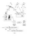
- FIG. 1illustrates an embodiment of a conventional asset tracking system that includes operations gateway 102 , communicating with MT 120 on an asset (or asset transporter).
- assetcan be embodied in various forms such as a trailer, a railcar, a shipping container, or the like.
- Satellite gateway 104communicates with satellite gateway 104 at the ground station and satellite modem 122 in MT 120 .
- Both satellite gateway 104 and satellite modem 122facilitate communication using one forward and one return link (frequency) over geosynchronous or geostationary (GEO) satellite 106 .
- GEOgeostationary
- the satellite communicationis implemented in a time division multiple access (TDMA) structure, which consists of 57600 time slots each day, per frequency or link, where each slot is 1.5 seconds long.
- operations gateway 102sends a message or packet to MT 120 on one of the 1.5 second slots.
- MT 120Upon receipt of this message or packet, MT 120 would then perform a GPS collection (e.g., code phase measurements) using global locating system (GLS) module 124 or to perform sensor measurements and transmit the data back to operations gateway 102 on the return link, on the same slot, delayed by a fixed time defined by the network.
- the fixed delaydefines a length of time that enables MT 120 to decode the forward packet, perform the data collection and processing, and build and transmit the return packet.
- MT 120can be configured to produce periodic status reports. In this configuration, MT 120 would wake up periodically, search for its assigned forward slot, perform data collection and processing, and transmit the status report on the assigned return slot. In another embodiment, MT 120 can be configured to produce a status report upon an occurrence of an event (e.g., door opening, motion detected, sensor reading, etc.). In this configuration, MT 120 would wake up upon occurrence of an event, search for an available forward slot, perform data collection and processing, and transmit the status report on the return slot corresponding to the identified available forward slot.
- an evente.g., door opening, motion detected, sensor reading, etc.
- operations gateway 102Upon receipt of a status report from MT 120 , operations gateway 102 passes the information to operations center 112 .
- Operations center 112can then use the received GPS collection to calculate a position solution using a least squares method. This position solution along with any other status information (both current and historical) can be passed to a customer via the Internet.
- an MTinitiates a position report in response to a gateway request packet sent to it.
- the MTmay obtain any information on preferred satellites from the forward packet or gateway-broadcast information.
- the MTnotes the precise timing of the forward (inbound or gateway-to-MT) packet and schedules position data collection and data reporting from this time.
- the MTdetects satellites in view by detecting the presence of radio energy at a GPS frequency using spreading codes specific to each satellite.
- the MTdetects the timing offsets for each code relative to a baseline, which could be, for example, time of measurement or any of the satellites' signal. After precise measurement, the MT encodes a return packet with the measured offsets for the code of each satellite observed and sends the packet to the gateway at a specific time offset from receipt of the forward packet.
- the round trip time for the MT's response to the forward packet transmissionis determined by subtracting known MT processing and scheduling delays, and calculating round trip time for the query-response transaction with the MT. If the MT sent an unsolicited position report, the packet sent in the forward timeslot corresponding to the timeslot containing the position report is used as the start time for round trip time measurement.
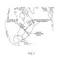
- An intersection arc on the surface of the earth for which the measured round trip time would applycan be determined, and the arc can be truncated with the outside boundaries of the satellite beam in which the MT operated.
- An example of a range intersection curveis illustrated in FIG. 2 .
- arbitrarily calculated seed positions along the arccan be used as starting points from which to calculate the closest point for which the reported code offsets from the MT would all apply.
- Several final positionscan result from this process within the area of operations. If more than one position results, the position with the best attributes is chosen as the true position of the MT. Attributes could include the solution's distance to the intersection arc calculated above, vertical distance from the known earth's surface elevation at the resulting points, mathematical residuals (measure of disagreement among multiple line crossings defining a solution position) for the solved point, etc.
- a GEO satelliteWhile a single GEO satellite can cover as much as 40 percent of the earth's surface, a GEO satellite is typically configured to focus its transmission and increase its signal strength over a defined service area. These large service areas can still dictate that a MT is configured to communicate with a single GEO satellite.
- an MTcan be provided that has the capability to communicate with LEO satellites to enable position determination by an operations center.
- LEO satellite networkis the Iridium satellite network.
- LEO satellitesorbit the earth between 400-1000 miles above the earth's surface. Because LEO satellites are not fixed in space in relation to the rotation of the earth, they move at very high speeds such that a LEO satellite can go across the visible horizon in approximately 10 minutes. When the first LEO satellite moves out to the horizon, another LEO satellite becomes available for communication. As the network of LEO satellites traverse the globe, so also does the MT tracking and data service area enabled by the LEO satellite network.
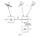
- FIG. 4illustrates an example of a LEO satellite network, wherein the satellite footprint and the plurality of beam footprints are shown for a single LEO satellite. Determination of a position of an asset using the LEO satellite network is now described with reference to the MT configuration of FIG. 5 and the position determination process of FIG. 6 .
- the MT configuration on an asset to be trackedincludes processor 510 and LEO modem 520 .
- processor 510 and LEO modem 520are coupled via interface 540 , such as an RS-232 interface.
- interface 540such as an RS-232 interface.
- LEO modem 520is Iridium's 9602 satellite data transceiver.
- processor 510a GLS processor that can be designed to collect code phase measurements from a plurality of GPS satellites. In one embodiment, in the absence of knowledge of a specific set of GPS applicable to the MT, processor 510 is designed to look for GPS signals from all 32 GPS satellites.
- processor 510is designed to look for GPS signals from a subset of the 32 GPS satellites.
- the MTcan be designed to further include GPS engine 530 , which is designed to determine a position based on received GPS satellite signals.
- GPS signalcontains three different types of information: a pseudorandom code that identifies which GPS satellite is transmitting information, ephemeris data that contains information about the status of the satellite (healthy or unhealthy), current date and time, and almanac data that tells GPS engine 530 where each GPS satellite should be at any time throughout the day.
- the assisting informationcan include current almanac information that would enable processor 510 to determine which GPS satellites are in view of the MT.
- GPS engine 530can be powered on periodically (e.g., every two weeks) to keep the almanac information current.
- the assisting informationcan include ephemeris information that would enable processor 510 to determine which GPS satellites are bad and should be excluded from the search.
- the assisting informationcan represent any information that can enable processor 510 to reduce the number of GPS satellites that are searched for.
- the number of GPS satellites that the MT searches forcan be reduced based on the relationship of the period of individual LEO satellites relative to the GPS constellation.
- the MTcan be designed to generate a table over time that identifies the GPS satellites in view relative to a LEO satellite's position. Each time the MT identifies a set of GPS satellites in view, the MT can store such information in a table that is indexed by a LEO satellite ID and its relative position in its satellite orbit period. As this table is generated over time, the MT can consult the table contents using the LEO satellite ID and satellite orbit period information to identify a list of GPS satellites that should be included in the search. This would obviate the need to perform a manual GPS satellite search.
- a table lookupdoes not yield a list of GPS satellites
- the subsequent list of GPS satellites that is identified in a searchcan be stored in the table relative to the LEO satellite ID and satellite orbit period for future reference.
- an index into a set of GPS satellites in viewis generated over time.
- This reduction of the number of GPS satellitesproduces an intelligent search that can reduce the time that processor 510 is active. For example, a search for all 32 GPS satellites can take 20 seconds, while a search for eight satellites can take approximately seven seconds.
- This reduction in time during which processor 510 is activeserves to further reduce the amount of power consumed by the MT in producing a scheduled or unscheduled position report. As would be appreciated, this reduction in time serves to reduce the amount of power consumed by the MT, thereby lengthening the service life of the battery that powers the MT.
- the lengthening of the service life of the batteryserves to reduce the maintenance costs associated with servicing the MTs deployed in the field.
- the timing of the code phase collection by processor 510is based on a hardware pulse generated by LEO modem 520 .
- This hardware pulsecan be generated in response to a modem request issued by processor 510 and represents a trigger for a collection of code phase measurement data by processor 510 .
- processor 510forwards the code phase measurement data to LEO modem 520 via interface 540 for delivery to the operations center.
- the LEO modemcan be designed to incorporate functionality that looks for GPS signals from a set of GPS satellites.
- interface 540is used by processor 510 to command LEO modem 520 to perform the data collection and processing.
- Interface 540can also be used to pass information to LEO modem 520 that can be used to reduce the search for GPS satellites. As would be appreciated, such information can also include a particular search order, a list of GPS satellites that should be ignored, and other configuration data that would enable LEO modem 520 to collect the necessary measurements in a reduced time period, thereby enabling conservation of power by the MT.
- LEO modem 520also provides in addition to the code phase measurement data, the LEO satellite ID, the beam ID, timing information that enables determination of the GPS collect time, and the propagation time from the MT to the LEO satellite. The use of this information by the operations center in determining a position of the MT is now described with reference to the flowchart of FIG. 6 .
- the processbegins at step 602 where the operations center uses the timing information to determine the collection time of the GPS code phase measurements.
- the operations centernext uses the two-line orbital elements (TLEs) to determine the xyz coordinates and velocity of the identified LEO satellite. Based on the determined xyz coordinates and velocity of the identified LEO satellite, the operations center can then determine, at step 606 , the center of the identified LEO satellite beam by consulting a static table of azimuths and central angles.
- TLEstwo-line orbital elements
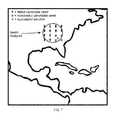
- the identification of the beam centerenables the operation center to generate, at step 608 , a set of candidate seed points based on the beam center.
- the footprint of the identified LEO satellite beamis relatively small, which allows for a manageable number of candidate seed points.
- a grid of candidate seed points over the beam footprintis defined (e.g., 5 ⁇ 5, 7 ⁇ 7, etc.).
- the operation centercan also receive a rough position estimate (e.g., latitude/longitude) of the MT along with a confidence estimate.
- this confidence estimatecan be in the form of a number of kilometers in which the MT is believed to be within a 70-80% certainty.
- the rough position estimatecan be used as a single seed candidate for determining a position solution. For example, if the confidence estimate indicates that the MT is believed to be within 40 kilometers of the rough position estimate with a 70-80% certainty, then the operations center can use the rough position estimate as a single seed candidate that would be sufficient to determine the location of the MT.
- a grid of candidate seed pointssuch as that illustrated in FIG. 7 need not be generated.
- a grid of candidate seed pointswould be generated by the operation center.
- a further benefit of receiving a rough position estimate (e.g., latitude/longitude) of the MTis that it can be used by the operation center to determine positioning of the various GPS satellites in view of the MT.
- This knowledge of the positioning of the GPS satellitescan be used to weed out code phase measurements from certain GPS satellites based on their angle of elevation.
- the MTcan be designed to search for and take measurements from all 32 GPS satellites, the knowledge of the positioning of the GPS satellites relative to the MT can enable the operation center to remove from consideration any measurements that can be considered unreliable.
- the operation centercan then apply, at step 610 , a least squares method to each candidate seed. As described in the communication process of U.S. Pat. No. 6,243,648, each candidate seed point will converge to a candidate solution.
- the slant range between the MT and the LEO satelliteis then determined using the propagation time.
- This slant rangecan be used at step 614 to cull the set of candidate solutions. More specifically, the difference between the candidate solution slant range and the determined slant range must be less than some nominal value.
- Altitudecan also be used to cull candidate solutions. Here, the altitude of the candidate solution must fall within some nominal range. This range can be tightened when terrain data is available.
- the root mean square of residual (RESRMS)can be used to cull candidate solutions. This metric, which results from the least squares method, characterizes how well the candidate solution matches the data from which it was derived. Lower values indicate better matches and the value of RESRMS must be less than some nominal value.
- the specific set of culls used at step 614would be implementation dependent.
- any candidate solutions that remainare examined to ensure that they all converge to very nearly the same location. If they do, then that location is considered to be the determined location of the MT.
- the solutioncan be refined using atmospheric models and other methods.
- a position determination process using multiple candidate seed pointscan be obviated based on the receipt by the operation center of a rough position estimate along with a sufficiently high confidence estimate.
- This high-level processis illustrated in the flowchart of FIG. 8 .
- the processbegins at step 802 where the operation center receives the rough position estimate of the MT along with the confidence estimate.
- the specific form of the rough position estimatee.g., latitude and longitude
- the confidence estimateis a structured mechanism by which the operation center can determine whether the rough position estimate is within a convergence zone around the MT.
- the convergence zonerefers to an area around the location of the MT in which a candidate seed point must lie to guarantee that the position calculation will converge to the location of the MT.
- the size of the convergence zone(see FIG. 3 ) will vary depending on number, quality and type of observation data used. In one example, the convergence zone for the code phase observations is approximately a radius of 75-80 km.
- an examination of the confidence estimate at step 804can determine whether the rough position estimate provided to the operation center is sufficient to produce a final position solution of the MT. Assume for example, that the confidence estimate provided indicates a 70% certainty that the rough position estimate is within 20 km of the location of the MT. In this example, the analysis at step 804 can generate a reliable indication that the rough position estimate is within the convergence zone of 75-80 km. Conversely, if the confidence estimate provided indicates a 50% certainty that the rough position estimate is within 90 km of the location of the MT, then the analysis at step 804 can generate an unreliable indication that the rough position estimate is within the convergence zone of 75-80 km.
- the unreliable indication generated at step 804would lead to a determination of a position solution using multiple candidate seed points such as that illustrated in FIG. 7 .
- an unreliable indication generated at step 804would yield to a position determination process such as that described in the flowchart of FIG. 6 .
- step 804If, on the other hand, the analysis at step 804 generates a reliable indication, then the process continues to step 806 where the operation center can use the rough position estimate as a single candidate seed point.
- the least squares methodis then applied to the single candidate seed point at step 808 to produce a single candidate solution.
- This single candidate solutionis used as the final position solution at step 810 .
- the application of a least squares method to a single candidate seed pointrepresents a vast computational savings as compared to the application of a least squares method to a grid of candidate seed points.
Landscapes
- Engineering & Computer Science (AREA)
- Radar, Positioning & Navigation (AREA)
- Remote Sensing (AREA)
- Physics & Mathematics (AREA)
- General Physics & Mathematics (AREA)
- Computer Networks & Wireless Communication (AREA)
- Position Fixing By Use Of Radio Waves (AREA)
Abstract
Description
Claims (5)
Priority Applications (2)
| Application Number | Priority Date | Filing Date | Title |
|---|---|---|---|
| US13/078,453US9784848B2 (en) | 2010-04-02 | 2011-04-01 | System and method for position determination using low earth orbit satellites |
| PCT/US2011/031039WO2011123846A1 (en) | 2010-04-02 | 2011-04-04 | System and method for position determination using low earth orbit satellites |
Applications Claiming Priority (4)
| Application Number | Priority Date | Filing Date | Title |
|---|---|---|---|
| US32061510P | 2010-04-02 | 2010-04-02 | |
| US38436610P | 2010-09-20 | 2010-09-20 | |
| US38825110P | 2010-09-30 | 2010-09-30 | |
| US13/078,453US9784848B2 (en) | 2010-04-02 | 2011-04-01 | System and method for position determination using low earth orbit satellites |
Publications (2)
| Publication Number | Publication Date |
|---|---|
| US20160109581A1 US20160109581A1 (en) | 2016-04-21 |
| US9784848B2true US9784848B2 (en) | 2017-10-10 |
Family
ID=44712660
Family Applications (1)
| Application Number | Title | Priority Date | Filing Date |
|---|---|---|---|
| US13/078,453Active2035-09-17US9784848B2 (en) | 2010-04-02 | 2011-04-01 | System and method for position determination using low earth orbit satellites |
Country Status (2)
| Country | Link |
|---|---|
| US (1) | US9784848B2 (en) |
| WO (1) | WO2011123846A1 (en) |
Families Citing this family (3)
| Publication number | Priority date | Publication date | Assignee | Title |
|---|---|---|---|---|
| JP5996467B2 (en)* | 2013-03-27 | 2016-09-21 | 株式会社日立ソリューションズ | Mobile body position information fraud detection apparatus, mobile body position information correction processing apparatus, and fraud detection program |
| US10181896B1 (en) | 2017-11-01 | 2019-01-15 | Hand Held Products, Inc. | Systems and methods for reducing power consumption in a satellite communication device |
| CN116961728B (en)* | 2023-07-27 | 2024-04-12 | 北京和德宇航技术有限公司 | Satellite coverage information determining method and device, electronic equipment and storage medium |
Citations (24)
| Publication number | Priority date | Publication date | Assignee | Title |
|---|---|---|---|---|
| US5758261A (en)* | 1995-06-06 | 1998-05-26 | Globalstar L.P. | Low earth orbit communication satellite gateway-to-gateway relay system |
| US5955986A (en) | 1997-11-20 | 1999-09-21 | Eagle Eye Technologies, Inc. | Low-power satellite-based geopositioning system |
| US5969669A (en)* | 1995-03-24 | 1999-10-19 | Kokusai Denshin Denwa Kabushiki Kaisha | Method for determining position of mobile earth station in satellite communication system |
| US6078284A (en)* | 1996-09-30 | 2000-06-20 | Qualcomm Incorporated | Passive position determination using two low-earth orbit satellites |
| US6107959A (en)* | 1996-09-30 | 2000-08-22 | Qualcomm Incorporated | Positioning determination using one low-Earth orbit satellite |
| US6169514B1 (en) | 1999-02-04 | 2001-01-02 | Eagle Eye Technologies, Inc. | Low-power satellite-based geopositioning system |
| US6243648B1 (en) | 1999-07-12 | 2001-06-05 | Eagle Eye, Inc. | Fast acquisition position reporting system |
| US6400319B1 (en) | 1998-09-01 | 2002-06-04 | Hughes Eelctronics Corporation | Communication network intialization apparatus and method for fast GPS-based positioning |
| US6480788B2 (en) | 1999-07-12 | 2002-11-12 | Eagle-Eye, Inc. | System and method for fast acquisition reporting using communication satellite range measurement |
| US20030058163A1 (en)* | 2000-01-24 | 2003-03-27 | Integrinautics Corporation, A California Corporation | Carrier-based differential-position determination using multi-frequency pseudolites |
| US6560536B1 (en)* | 1999-07-12 | 2003-05-06 | Eagle-Eye, Inc. | System and method for rapid telepositioning |
| US6725158B1 (en) | 1999-07-12 | 2004-04-20 | Skybitz, Inc. | System and method for fast acquisition reporting using communication satellite range measurement |
| US6807158B2 (en)* | 2001-08-07 | 2004-10-19 | Hrl Laboratories, Llc | Method and apparatus for determining position and trajectory of gateways to optimize performance in hybrid non-terrestrial-terrestrial multi-hop mobile networks |
| US7092725B2 (en)* | 2001-10-25 | 2006-08-15 | Qualcomm Incorporated | Aiding beam identification in a satellite system |
| US20080233866A1 (en)* | 2007-02-21 | 2008-09-25 | Richard Burtner | Satellite aided location tracking and data services using geosynchronous and low earth orbit satellites |
| US20080233970A1 (en)* | 2007-02-22 | 2008-09-25 | Richard Burtner | Satellite aided location tracking and data services using geosynchronous and low earth orbit satellites with global locating system |
| US7583225B2 (en) | 2006-05-18 | 2009-09-01 | The Boeing Company | Low earth orbit satellite data uplink |
| US7623871B2 (en)* | 2002-04-24 | 2009-11-24 | Qualcomm Incorporated | Position determination for a wireless terminal in a hybrid position determination system |
| US7782811B2 (en)* | 2005-04-05 | 2010-08-24 | Skybitz, Inc. | Multiple return link |
| US8155640B1 (en)* | 2005-06-09 | 2012-04-10 | Skybitz, Inc. | System and method for mobile terminal initiated satellite communications |
| US8830124B1 (en)* | 2010-09-17 | 2014-09-09 | Skybitz, Inc. | System and method for asset tracking configuration of a mobile terminal |
| US20140266867A1 (en)* | 2013-03-13 | 2014-09-18 | Northrop Grumman Systems Corporation | Adaptive coded modulation in low earth orbit satellite communication system |
| US9213103B2 (en)* | 2008-05-30 | 2015-12-15 | The Boeing Company | Cells obtaining timing and positioning by using satellite systems with high power signals for improved building penetration |
| US9661483B2 (en)* | 2014-06-20 | 2017-05-23 | Enrico Bastianelli | Multi-function emergency assistance request, tracking, and communication system |
- 2011
- 2011-04-01USUS13/078,453patent/US9784848B2/enactiveActive
- 2011-04-04WOPCT/US2011/031039patent/WO2011123846A1/enactiveApplication Filing
Patent Citations (27)
| Publication number | Priority date | Publication date | Assignee | Title |
|---|---|---|---|---|
| US5969669A (en)* | 1995-03-24 | 1999-10-19 | Kokusai Denshin Denwa Kabushiki Kaisha | Method for determining position of mobile earth station in satellite communication system |
| US5758261A (en)* | 1995-06-06 | 1998-05-26 | Globalstar L.P. | Low earth orbit communication satellite gateway-to-gateway relay system |
| US6078284A (en)* | 1996-09-30 | 2000-06-20 | Qualcomm Incorporated | Passive position determination using two low-earth orbit satellites |
| US6107959A (en)* | 1996-09-30 | 2000-08-22 | Qualcomm Incorporated | Positioning determination using one low-Earth orbit satellite |
| US5955986A (en) | 1997-11-20 | 1999-09-21 | Eagle Eye Technologies, Inc. | Low-power satellite-based geopositioning system |
| US6094162A (en) | 1997-11-20 | 2000-07-25 | Eagle Eye Technologies, Inc. | Low-power satellite-based geopositioning system |
| US6154171A (en) | 1997-11-20 | 2000-11-28 | Eagle Eye Technologies, Inc. | Low-power satellite-based geopositioning system |
| US6400319B1 (en) | 1998-09-01 | 2002-06-04 | Hughes Eelctronics Corporation | Communication network intialization apparatus and method for fast GPS-based positioning |
| US6169514B1 (en) | 1999-02-04 | 2001-01-02 | Eagle Eye Technologies, Inc. | Low-power satellite-based geopositioning system |
| US6560536B1 (en)* | 1999-07-12 | 2003-05-06 | Eagle-Eye, Inc. | System and method for rapid telepositioning |
| US6243648B1 (en) | 1999-07-12 | 2001-06-05 | Eagle Eye, Inc. | Fast acquisition position reporting system |
| US6725158B1 (en) | 1999-07-12 | 2004-04-20 | Skybitz, Inc. | System and method for fast acquisition reporting using communication satellite range measurement |
| US6480788B2 (en) | 1999-07-12 | 2002-11-12 | Eagle-Eye, Inc. | System and method for fast acquisition reporting using communication satellite range measurement |
| US20030058163A1 (en)* | 2000-01-24 | 2003-03-27 | Integrinautics Corporation, A California Corporation | Carrier-based differential-position determination using multi-frequency pseudolites |
| EP1346236B1 (en) | 2000-10-27 | 2009-06-10 | Skybitz, Inc. | System and method for rapid telepositioning |
| US6807158B2 (en)* | 2001-08-07 | 2004-10-19 | Hrl Laboratories, Llc | Method and apparatus for determining position and trajectory of gateways to optimize performance in hybrid non-terrestrial-terrestrial multi-hop mobile networks |
| US7092725B2 (en)* | 2001-10-25 | 2006-08-15 | Qualcomm Incorporated | Aiding beam identification in a satellite system |
| US7623871B2 (en)* | 2002-04-24 | 2009-11-24 | Qualcomm Incorporated | Position determination for a wireless terminal in a hybrid position determination system |
| US7782811B2 (en)* | 2005-04-05 | 2010-08-24 | Skybitz, Inc. | Multiple return link |
| US8155640B1 (en)* | 2005-06-09 | 2012-04-10 | Skybitz, Inc. | System and method for mobile terminal initiated satellite communications |
| US7583225B2 (en) | 2006-05-18 | 2009-09-01 | The Boeing Company | Low earth orbit satellite data uplink |
| US20080233866A1 (en)* | 2007-02-21 | 2008-09-25 | Richard Burtner | Satellite aided location tracking and data services using geosynchronous and low earth orbit satellites |
| US20080233970A1 (en)* | 2007-02-22 | 2008-09-25 | Richard Burtner | Satellite aided location tracking and data services using geosynchronous and low earth orbit satellites with global locating system |
| US9213103B2 (en)* | 2008-05-30 | 2015-12-15 | The Boeing Company | Cells obtaining timing and positioning by using satellite systems with high power signals for improved building penetration |
| US8830124B1 (en)* | 2010-09-17 | 2014-09-09 | Skybitz, Inc. | System and method for asset tracking configuration of a mobile terminal |
| US20140266867A1 (en)* | 2013-03-13 | 2014-09-18 | Northrop Grumman Systems Corporation | Adaptive coded modulation in low earth orbit satellite communication system |
| US9661483B2 (en)* | 2014-06-20 | 2017-05-23 | Enrico Bastianelli | Multi-function emergency assistance request, tracking, and communication system |
Non-Patent Citations (2)
| Title |
|---|
| International Preliminary Report on Patentability, Oct. 11, 2012. |
| International Search Report and Written Opinion, Jun. 24, 2011. |
Also Published As
| Publication number | Publication date |
|---|---|
| US20160109581A1 (en) | 2016-04-21 |
| WO2011123846A1 (en) | 2011-10-06 |
Similar Documents
| Publication | Publication Date | Title |
|---|---|---|
| US9841506B2 (en) | System and method for dual-mode location determination | |
| US6243648B1 (en) | Fast acquisition position reporting system | |
| US6560536B1 (en) | System and method for rapid telepositioning | |
| CA2426954C (en) | System and method for fast acquisition reporting using communication satellite range measurement | |
| US6725158B1 (en) | System and method for fast acquisition reporting using communication satellite range measurement | |
| US6400319B1 (en) | Communication network intialization apparatus and method for fast GPS-based positioning | |
| US8630796B2 (en) | System and method for fast acquisition position reporting | |
| US11234205B2 (en) | Mobile transceiver having route monitoring and method of operation | |
| US20020149515A1 (en) | Method for positioning, a positioning system, and an electronic device | |
| JP2018534537A (en) | Method and system for joint global navigation satellite system (GNSS) diagnostics | |
| WO2022003386A1 (en) | Methods for the transmission of data between a plurality of resource-constrained devices and a non-geostationary satellite and associated system | |
| US9482758B2 (en) | System and method for using data phase to reduce position ambiguities | |
| BR102016014224A2 (en) | gnss receiver capable of deploying optimal error correction mode | |
| US8010127B2 (en) | Satellite aided location tracking and data services using geosynchronous and low earth orbit satellites with global locating system | |
| US9784848B2 (en) | System and method for position determination using low earth orbit satellites | |
| US6195042B1 (en) | Method of locating a fixed terminal using a constellation of satellites | |
| Dong et al. | GNSS-5G Hybrid Positioning and Adaptive Switchover Strategy Based on Observable Data for Smart Logistics | |
| WO2008103557A1 (en) | Satellite aided location tracking and data services using geo and leo satellites | |
| Martini et al. | Characterization of the galileo ranging accuracy and integrity performance: Methodologies and results | |
| JP2002267739A (en) | Recognition system for real-time self-difference position in local area, method of recognizing position of mobile station using the system, and recognition system for terminal position |
Legal Events
| Date | Code | Title | Description |
|---|---|---|---|
| AS | Assignment | Owner name:SKYBITZ, INC., VIRGINIA Free format text:ASSIGNMENT OF ASSIGNORS INTEREST;ASSIGNORS:HARVEY, MICHAEL;MALONE, CRAIG;SHANKAR, UDAY;AND OTHERS;REEL/FRAME:026466/0203 Effective date:20110620 | |
| AS | Assignment | Owner name:SILICON VALLEY BANK, CALIFORNIA Free format text:SECURITY AGREEMENT;ASSIGNOR:SKYBITZ, INC.;REEL/FRAME:027645/0702 Effective date:20120201 | |
| AS | Assignment | Owner name:SUNTRUST BANK, AS FIRST LIEN ADMINISTRATIVE AGENT, Free format text:SECURITY AGREEMENT;ASSIGNORS:TELULAR CORPORATION;SKYBITZ, INC.;REEL/FRAME:030724/0331 Effective date:20130624 | |
| AS | Assignment | Owner name:SUNTRUST BANK, AS SECOND LIEN ADMINISTRATIVE AGENT Free format text:SECURITY AGREEMENT;ASSIGNORS:TELULAR CORPORATION;SKYBITZ, INC.;REEL/FRAME:030739/0932 Effective date:20130624 | |
| AS | Assignment | Owner name:SKYBITZ, INC., ILLINOIS Free format text:RELEASE BY SECURED PARTY;ASSIGNOR:SILICON VALLEY BANK;REEL/FRAME:030754/0239 Effective date:20130624 Owner name:TANKLINK CORPORATION, ILLINOIS Free format text:RELEASE BY SECURED PARTY;ASSIGNOR:SILICON VALLEY BANK;REEL/FRAME:030754/0239 Effective date:20130624 Owner name:TELULAR CORPORATION, ILLINOIS Free format text:RELEASE BY SECURED PARTY;ASSIGNOR:SILICON VALLEY BANK;REEL/FRAME:030754/0239 Effective date:20130624 | |
| AS | Assignment | Owner name:TELULAR CORPORATON, ILLINOIS Free format text:RELEASE BY SECURED PARTY;ASSIGNOR:SUNTRUST BANK, AS ADMINISTRATIVE AGENT;REEL/FRAME:036084/0195 Effective date:20150708 Owner name:SKYBITZ, INC., ILLINOIS Free format text:RELEASE BY SECURED PARTY;ASSIGNOR:SUNTRUST BANK, AS ADMINISTRATIVE AGENT;REEL/FRAME:036084/0195 Effective date:20150708 | |
| STCF | Information on status: patent grant | Free format text:PATENTED CASE | |
| AS | Assignment | Owner name:TELULAR CORPORATION, ILLINOIS Free format text:RELEASE BY SECURED PARTY;ASSIGNOR:SUNTRUST BANK;REEL/FRAME:047719/0345 Effective date:20181024 Owner name:SKYBITZ, INC., ILLINOIS Free format text:RELEASE BY SECURED PARTY;ASSIGNOR:SUNTRUST BANK;REEL/FRAME:047719/0345 Effective date:20181024 | |
| FEPP | Fee payment procedure | Free format text:MAINTENANCE FEE REMINDER MAILED (ORIGINAL EVENT CODE: REM.); ENTITY STATUS OF PATENT OWNER: LARGE ENTITY | |
| FEPP | Fee payment procedure | Free format text:SURCHARGE FOR LATE PAYMENT, LARGE ENTITY (ORIGINAL EVENT CODE: M1554); ENTITY STATUS OF PATENT OWNER: LARGE ENTITY | |
| MAFP | Maintenance fee payment | Free format text:PAYMENT OF MAINTENANCE FEE, 4TH YEAR, LARGE ENTITY (ORIGINAL EVENT CODE: M1551); ENTITY STATUS OF PATENT OWNER: LARGE ENTITY Year of fee payment:4 | |
| MAFP | Maintenance fee payment | Free format text:PAYMENT OF MAINTENANCE FEE, 8TH YEAR, LARGE ENTITY (ORIGINAL EVENT CODE: M1552); ENTITY STATUS OF PATENT OWNER: LARGE ENTITY Year of fee payment:8 |