US9784820B2 - Radar system with phase based multi-target detection - Google Patents
Radar system with phase based multi-target detectionDownload PDFInfo
- Publication number
- US9784820B2 US9784820B2US14/491,192US201414491192AUS9784820B2US 9784820 B2US9784820 B2US 9784820B2US 201414491192 AUS201414491192 AUS 201414491192AUS 9784820 B2US9784820 B2US 9784820B2
- Authority
- US
- United States
- Prior art keywords
- frequency
- antenna
- phase
- profile
- detected
- Prior art date
- Legal status (The legal status is an assumption and is not a legal conclusion. Google has not performed a legal analysis and makes no representation as to the accuracy of the status listed.)
- Active, expires
Links
Images


Classifications
- G—PHYSICS
- G01—MEASURING; TESTING
- G01S—RADIO DIRECTION-FINDING; RADIO NAVIGATION; DETERMINING DISTANCE OR VELOCITY BY USE OF RADIO WAVES; LOCATING OR PRESENCE-DETECTING BY USE OF THE REFLECTION OR RERADIATION OF RADIO WAVES; ANALOGOUS ARRANGEMENTS USING OTHER WAVES
- G01S13/00—Systems using the reflection or reradiation of radio waves, e.g. radar systems; Analogous systems using reflection or reradiation of waves whose nature or wavelength is irrelevant or unspecified
- G01S13/88—Radar or analogous systems specially adapted for specific applications
- G—PHYSICS
- G01—MEASURING; TESTING
- G01S—RADIO DIRECTION-FINDING; RADIO NAVIGATION; DETERMINING DISTANCE OR VELOCITY BY USE OF RADIO WAVES; LOCATING OR PRESENCE-DETECTING BY USE OF THE REFLECTION OR RERADIATION OF RADIO WAVES; ANALOGOUS ARRANGEMENTS USING OTHER WAVES
- G01S7/00—Details of systems according to groups G01S13/00, G01S15/00, G01S17/00
- G01S7/02—Details of systems according to groups G01S13/00, G01S15/00, G01S17/00 of systems according to group G01S13/00
- G01S7/41—Details of systems according to groups G01S13/00, G01S15/00, G01S17/00 of systems according to group G01S13/00 using analysis of echo signal for target characterisation; Target signature; Target cross-section
- G—PHYSICS
- G01—MEASURING; TESTING
- G01S—RADIO DIRECTION-FINDING; RADIO NAVIGATION; DETERMINING DISTANCE OR VELOCITY BY USE OF RADIO WAVES; LOCATING OR PRESENCE-DETECTING BY USE OF THE REFLECTION OR RERADIATION OF RADIO WAVES; ANALOGOUS ARRANGEMENTS USING OTHER WAVES
- G01S13/00—Systems using the reflection or reradiation of radio waves, e.g. radar systems; Analogous systems using reflection or reradiation of waves whose nature or wavelength is irrelevant or unspecified
- G01S13/02—Systems using reflection of radio waves, e.g. primary radar systems; Analogous systems
- G01S13/06—Systems determining position data of a target
- G01S13/42—Simultaneous measurement of distance and other co-ordinates
- G01S13/44—Monopulse radar, i.e. simultaneous lobing
- G01S13/4454—Monopulse radar, i.e. simultaneous lobing phase comparisons monopulse, i.e. comparing the echo signals received by an interferometric antenna arrangement
- G—PHYSICS
- G01—MEASURING; TESTING
- G01S—RADIO DIRECTION-FINDING; RADIO NAVIGATION; DETERMINING DISTANCE OR VELOCITY BY USE OF RADIO WAVES; LOCATING OR PRESENCE-DETECTING BY USE OF THE REFLECTION OR RERADIATION OF RADIO WAVES; ANALOGOUS ARRANGEMENTS USING OTHER WAVES
- G01S13/00—Systems using the reflection or reradiation of radio waves, e.g. radar systems; Analogous systems using reflection or reradiation of waves whose nature or wavelength is irrelevant or unspecified
- G01S13/02—Systems using reflection of radio waves, e.g. primary radar systems; Analogous systems
- G01S13/50—Systems of measurement based on relative movement of target
- G01S13/58—Velocity or trajectory determination systems; Sense-of-movement determination systems
- G01S13/583—Velocity or trajectory determination systems; Sense-of-movement determination systems using transmission of continuous unmodulated waves, amplitude-, frequency-, or phase-modulated waves and based upon the Doppler effect resulting from movement of targets
- G01S13/584—Velocity or trajectory determination systems; Sense-of-movement determination systems using transmission of continuous unmodulated waves, amplitude-, frequency-, or phase-modulated waves and based upon the Doppler effect resulting from movement of targets adapted for simultaneous range and velocity measurements
- G—PHYSICS
- G01—MEASURING; TESTING
- G01S—RADIO DIRECTION-FINDING; RADIO NAVIGATION; DETERMINING DISTANCE OR VELOCITY BY USE OF RADIO WAVES; LOCATING OR PRESENCE-DETECTING BY USE OF THE REFLECTION OR RERADIATION OF RADIO WAVES; ANALOGOUS ARRANGEMENTS USING OTHER WAVES
- G01S13/00—Systems using the reflection or reradiation of radio waves, e.g. radar systems; Analogous systems using reflection or reradiation of waves whose nature or wavelength is irrelevant or unspecified
- G01S13/88—Radar or analogous systems specially adapted for specific applications
- G01S13/93—Radar or analogous systems specially adapted for specific applications for anti-collision purposes
- G01S13/931—Radar or analogous systems specially adapted for specific applications for anti-collision purposes of land vehicles
- G—PHYSICS
- G01—MEASURING; TESTING
- G01S—RADIO DIRECTION-FINDING; RADIO NAVIGATION; DETERMINING DISTANCE OR VELOCITY BY USE OF RADIO WAVES; LOCATING OR PRESENCE-DETECTING BY USE OF THE REFLECTION OR RERADIATION OF RADIO WAVES; ANALOGOUS ARRANGEMENTS USING OTHER WAVES
- G01S7/00—Details of systems according to groups G01S13/00, G01S15/00, G01S17/00
- G01S7/02—Details of systems according to groups G01S13/00, G01S15/00, G01S17/00 of systems according to group G01S13/00
- G01S7/28—Details of pulse systems
- G01S7/285—Receivers
- G01S7/292—Extracting wanted echo-signals
- G01S7/2921—Extracting wanted echo-signals based on data belonging to one radar period
- G—PHYSICS
- G01—MEASURING; TESTING
- G01S—RADIO DIRECTION-FINDING; RADIO NAVIGATION; DETERMINING DISTANCE OR VELOCITY BY USE OF RADIO WAVES; LOCATING OR PRESENCE-DETECTING BY USE OF THE REFLECTION OR RERADIATION OF RADIO WAVES; ANALOGOUS ARRANGEMENTS USING OTHER WAVES
- G01S7/00—Details of systems according to groups G01S13/00, G01S15/00, G01S17/00
- G01S7/02—Details of systems according to groups G01S13/00, G01S15/00, G01S17/00 of systems according to group G01S13/00
- G01S7/35—Details of non-pulse systems
- G01S7/352—Receivers
- G01S7/354—Extracting wanted echo-signals
- G—PHYSICS
- G01—MEASURING; TESTING
- G01S—RADIO DIRECTION-FINDING; RADIO NAVIGATION; DETERMINING DISTANCE OR VELOCITY BY USE OF RADIO WAVES; LOCATING OR PRESENCE-DETECTING BY USE OF THE REFLECTION OR RERADIATION OF RADIO WAVES; ANALOGOUS ARRANGEMENTS USING OTHER WAVES
- G01S7/00—Details of systems according to groups G01S13/00, G01S15/00, G01S17/00
- G01S7/02—Details of systems according to groups G01S13/00, G01S15/00, G01S17/00 of systems according to group G01S13/00
- G01S7/41—Details of systems according to groups G01S13/00, G01S15/00, G01S17/00 of systems according to group G01S13/00 using analysis of echo signal for target characterisation; Target signature; Target cross-section
- G01S7/411—Identification of targets based on measurements of radar reflectivity
- G01S7/412—Identification of targets based on measurements of radar reflectivity based on a comparison between measured values and known or stored values
- G—PHYSICS
- G01—MEASURING; TESTING
- G01S—RADIO DIRECTION-FINDING; RADIO NAVIGATION; DETERMINING DISTANCE OR VELOCITY BY USE OF RADIO WAVES; LOCATING OR PRESENCE-DETECTING BY USE OF THE REFLECTION OR RERADIATION OF RADIO WAVES; ANALOGOUS ARRANGEMENTS USING OTHER WAVES
- G01S7/00—Details of systems according to groups G01S13/00, G01S15/00, G01S17/00
- G01S7/02—Details of systems according to groups G01S13/00, G01S15/00, G01S17/00 of systems according to group G01S13/00
- G01S7/41—Details of systems according to groups G01S13/00, G01S15/00, G01S17/00 of systems according to group G01S13/00 using analysis of echo signal for target characterisation; Target signature; Target cross-section
- G01S7/414—Discriminating targets with respect to background clutter
- G—PHYSICS
- G01—MEASURING; TESTING
- G01S—RADIO DIRECTION-FINDING; RADIO NAVIGATION; DETERMINING DISTANCE OR VELOCITY BY USE OF RADIO WAVES; LOCATING OR PRESENCE-DETECTING BY USE OF THE REFLECTION OR RERADIATION OF RADIO WAVES; ANALOGOUS ARRANGEMENTS USING OTHER WAVES
- G01S13/00—Systems using the reflection or reradiation of radio waves, e.g. radar systems; Analogous systems using reflection or reradiation of waves whose nature or wavelength is irrelevant or unspecified
- G01S13/66—Radar-tracking systems; Analogous systems
- G01S13/72—Radar-tracking systems; Analogous systems for two-dimensional tracking, e.g. combination of angle and range tracking, track-while-scan radar
- G01S13/723—Radar-tracking systems; Analogous systems for two-dimensional tracking, e.g. combination of angle and range tracking, track-while-scan radar by using numerical data
- G01S13/726—Multiple target tracking
- G—PHYSICS
- G01—MEASURING; TESTING
- G01S—RADIO DIRECTION-FINDING; RADIO NAVIGATION; DETERMINING DISTANCE OR VELOCITY BY USE OF RADIO WAVES; LOCATING OR PRESENCE-DETECTING BY USE OF THE REFLECTION OR RERADIATION OF RADIO WAVES; ANALOGOUS ARRANGEMENTS USING OTHER WAVES
- G01S13/00—Systems using the reflection or reradiation of radio waves, e.g. radar systems; Analogous systems using reflection or reradiation of waves whose nature or wavelength is irrelevant or unspecified
- G01S13/02—Systems using reflection of radio waves, e.g. primary radar systems; Analogous systems
- G01S2013/0236—Special technical features
- G01S2013/0245—Radar with phased array antenna
Definitions
- This disclosuregenerally relates to a radar system, and more particularly relates to a system that determines if a target includes more than one object based on a comparison of phases of detected signals from multiple receive antennas.
- automotive radar sensorsmay have performance limitations with regard to discriminating two objects that have similar position and Doppler shift characteristics, or if one object has a substantially larger Radar Cross Section (RCS) than a second nearby object.
- RCSRadar Cross Section
- Examples of two objects with similar range and Doppler shift reflection characteristics that typical automotive radar systems have difficulty discerninginclude: a slowly moving pedestrian walking around stationary or slowly moving passenger vehicle, a motor cycle traveling beside a tractor-trailer traveling in an adjacent lane at a similar range and range rate, and two passenger cars moving close to each other on adjacent lanes with similar range rates.
- Automotive systemssuch as Autonomous Intelligent Cruise Control, Collision Warning and Mitigation, and Blind Spot Detection use a radar sensor to detect objects proximate to the vehicle.
- Reflected radar signalsare detected by an antenna array are typically converted to a discreet base band, then transformed from the time-domain to the frequency-domain where amplitude profiles indicative of each signal detected by each receive antenna element are integrated non-coherently.
- Automotive radarsoften use this non-coherently integrated (NCI) amplitude profile for object detection to determine position (i.e. range) and Doppler parameters (i.e. range-rate) of detected objects with profile magnitudes greater than a defined detection threshold.
- the NCI-detection techniqueis preferred as it suppresses noise variation to avoid false alarms. While NCI may degrade information in the detected signals, it does so less than the noise variance as system noise is less correlated across the antenna elements when compared to the reflected radar signal. As such, NCI provides a net gain in signal-to-noise ratio.
- NCI-detection techniqueshave performance limitations for detection and discrimination of multiple objects that are near each other. That is, if two objects have similar position and Doppler characteristics, and the reflection characteristics or Radar Cross Sections (RCS) to the objects are significantly different, then the reflected radar signal from the object with the larger RCS may mask the reflected radar signal from target with smaller RCS, and thereby makes second target identification and/or discrimination difficult. Examples of this situation include a slowly moving pedestrian near a stationary passenger vehicle, a motor cycle moving with nearly the same range and Doppler as a tractor-trailer type vehicle in an adjacent lane, and two passenger vehicles moving close to each other on adjacent lanes with nearly the same range and Doppler.
- RCSRadar Cross Sections
- the performance limitations of near targets detection and discrimination of the detection technique using amplitude spectrum peak detection and evaluation techniqueis solved by local phase spectrum evaluation technique.
- reflected radar signals from each scattering centerinterfere with each other differently at the various receive antenna elements depending on the relative position difference of the various scattering centers with respect to the receive antenna position.
- Relative position difference between scattering centersis expressed in terms of relative phase difference between the reflected radar signals from the various scattering centers, and it determines interference characteristics at the receive antenna. That means that various antenna-array elements receive dissimilar interference characteristics of reflected radar signals from these scattering centers due to the fact that relative phase difference changes across distributed antenna elements.
- a phase difference of detected signals from each receive antenna elementcan be evaluated in the frequency domain local to the superposed signal frequency bin. For example, a phase difference may be calculated between the first symmetrical (i.e. first higher and lower) frequency bins to the superposed signal detection frequency bin. The phase difference converges to a minimum value (or zero) if detected signals are from a single point scattering center. This is because signal amplitude and phase spectrums are generally spread equally to neighboring frequency bins as far as the time domain signal is weighted by symmetrical window coefficients about the window maximum at the center. In case of reflected radar signal interference from multiple nearby scattering centers, these first symmetrical frequency bins should contain different signal phase values as far as scattering centers possess a relative position difference.
- phase difference across the antenna-array elementsFor antenna-array configurations, averaging of the phase difference across the antenna-array elements provides a robust phase difference value that can be used to distinguish a single point scattering center from multiple near scattering centers. As discussed, there is also phase difference variation across antenna-array elements due to the fact that the relative position difference of scattering centers are not equal for distributed antenna-array configuration. Therefore, evaluating the slope or standard deviation of the phase difference across antenna-array elements can also be employed to distinguish single scattering center from multiple near scattering centers.
- a local phase spectrum evaluation techniqueby itself does not provide parameter estimation of the scattering centers as it was the case for the detection and discrimination techniques described by Hassen (application. Ser. No. 14/277,894). However, it is more sensitive to distinguish a reflection of a single scattering center from multiple near to each other scattering centers. It can be then used as indicator to activate controlled parameter estimation techniques such as the amplitude spectrum peak detection and evaluation technique using an “or-logic” single channel detection technique as described by Alebel Arage Hassen (application. Ser. No. 14/277,894), or a complex spectrum evaluation technique using space-time adaptive processing.
- this local phase spectrum evaluation techniquecan also be used to let the system define Range-Doppler Near-Objects Detection zone (RDNOD-zone) about the NCI-detection if activation of parameter estimation technique is not realistic. This will assist optimal usage of limited signal processing resources while enhancing identification of multiple near scattering centers.
- RNOD-zoneRange-Doppler Near-Objects Detection zone
- phase difference evaluation techniqueas opposed to an absolute phase evaluation, it is less susceptible to mismatch between antenna-array elements as well as any transients effects. However, it is recommended to apply this technique for detections only with adequate signal-to-noise ratio. Phase in general is susceptible to noise, and results from phase difference evaluation may not be reliable for detections with inadequate signal-to-noise ratio.
- phase differencefluctuates over time if the scattering centers are in continuous motion and trigger relative position variance with time.
- time domain variancefluctuation
- the time domain variance (fluctuation) of the standard deviation of the phase differenceprovides further information that can be employed to distinctly classify or categorize various object groups and their motion profiles, for example, to distinguish pedestrians, bicyclists, and vehicles moving at an angle relative to the host vehicle from vehicles traveling straight forward or longitudinally relative to the host vehicle.
- a radar systemincludes a plurality of antennas and a controller.
- the plurality of antennasis configured to detect a reflected radar signal reflected by an object in a field-of-view of the system.
- Each antenna of the plurality of antennasis configured to output a detected signal indicative of the reflected radar signal detected by the antenna.
- the controlleris configured to receive detected signals from the plurality of antennas, and determine if a target is present in the field-of-view based on the detected signals.
- the controlleris also configured to determine if the target includes more than one object based on an analysis of phases of the detected signals.
- a controller for a radar systemincludes a receiver and a processor.
- the receiveris configured to receive detected signals from a plurality of antennas configured to detect a reflected radar signal reflected by an object in a field-of-view of the system.
- Each antenna of the plurality of antennasis configured to output a detected signal indicative of the reflected radar signal detected by each of the antenna.
- the processoris configured to receive the detected signals from the plurality of antennas, determine if a target is present in the field-of-view based on the detected signals, and determine if the target includes more than one object based on an analysis of phases of the detected signals.
- a method of operating a radar systemincludes the step of receiving detected signals from a plurality of antennas configured to detect a reflected radar signal reflected by an object in a field-of-view of the antennas. Each antenna of the plurality of antennas is configured to output a detected signal indicative of the reflected radar signal detected by each of the antenna. The method also includes the step of determining if a target is present in the field-of-view based on the detected signals. The method also includes the step of determining if the target includes more than one object based on an analysis of phases of the detected signals.
- FIG. 1is a diagram of a radar system in accordance with one embodiment
- FIG. 2is a graph of signal present in the system of FIG. 1 in accordance with one embodiment
- FIG. 3is a graph of signal present in the system of FIG. 1 in accordance with one embodiment
- FIG. 4is a graph of data present in the system of FIG. 1 in accordance with one embodiment
- FIG. 5is a graph of data present in the system of FIG. 1 in accordance with one embodiment.
- FIG. 6is a flowchart of a method executed by the system of FIG. 1 in accordance with one embodiment.
- FIG. 1illustrates a non-limiting example of a radar system, hereafter referred to as the system 10 .
- the system 10includes an antenna array 12 that may include a transmit-element 14 , and an array of receive elements, hereafter referred to as a plurality of antennas 16 . It is recognized that one or more of the antenna elements that make up the antenna array 12 could be used to both transmit a radar signal 18 , and output a detected signal 30 indicative of reflected radar signals 20 reflected by a first object 24 A or a second object 24 B in a field-of-view 22 of the system 10 .
- the transmit-element 14 and the plurality of antennas 16are illustrated as distinct elements in this example only to simplify the explanation of the system 10 .
- the system 10may also include a controller 26 configured to output a transmit-signal 28 to the transmit-element 14 , and configured to receive detected signals 30 from each antenna, for example a first signal 30 A from a first antenna 16 A and a second signal 30 B from a second antenna 16 B. Each of the detected signals 30 correspond to the reflected radar signal 20 that was detected by one of the plurality of antennas 16 .
- the controller 26may include a processor 27 such as a microprocessor, digital signal processor, or other control/signal conditioning circuitry such as analog and/or digital control circuitry including an application specific integrated circuit (ASIC) for processing data, as should be evident to those in the art.
- ASICapplication specific integrated circuit
- the controller 26may include memory (not shown), including non-volatile memory, such as electrically erasable programmable read-only memory (EEPROM) for storing one or more routines, thresholds and captured data.
- the one or more routinesmay be executed by the processor 27 to perform steps for determining if the detected signals 30 received by the controller 26 indicate the presence of the first object 24 A or the second object 24 B, as described herein.
- the transmit-element 14radiates or emits the radar signal 18 toward the first object 24 A and/or the second object 24 B in a field-of-view 22
- the plurality of antennas 16each detect a reflected radar signal reflected by the first object 24 A and/or the second object 24 B in the field-of-view 22 of the system 10 .
- Characteristics of the reflected radar signal 20depend on a backscatter property or radar cross section (RCS) of the first object 24 A or the second object 24 B.
- RCSradar cross section
- the characteristicsalso depend on distance, direction, and relative motion of the first object 24 A and/or the second object 24 B relative to the antenna array 12 , which influences the Doppler shift of the reflected radar signal 20 .
- the controller 26may transform the time domain signals (the detected signals 30 ) to the frequency domain so, for example, the spectrums can be combined using, for example, non-coherent integration (NCI).
- NCInon-coherent integration
- Some automotive radar systemsuse this non-coherently integrated spectral data as the basis for object detection, and evaluate the spectral data to determine the position and Doppler parameter estimates that have higher spectral magnitude than a defined detection threshold.
- NCIis generally preferred to suppress noise induced variation and thereby keep noise induced false alarm rates to a minimum.
- the reflected radar signal 20may interfere with each other depending on the relative position and/or range rate difference between the objects with respect to the receive antennas (the plurality of antennas 16 ).
- a relative position difference between the first object 24 A and the second object 24 Bis illustrated as Arx and Ary and may be exhibited in terms of a relative phase difference between the reflected radar signal 20 detected by the antennas 16 from these scattering centers. That may cause the detected signals 30 to exhibit dissimilar interference characteristics for the signals from the scattering centers of the objects due to the fact that the relative phase difference changes across the plurality of antennas 16 .
- Applicant's prior system described in U.S. patent application Ser. No. 14/277,894 filed 15 May 2014applies a composite detection strategy based on NCI spectrum together with a single receive channel spectrum analysis using ‘or logic’ in order to improve automotive radar range, range rate, and angle measurement resolution, and enhance system performance for near targets discrimination, target imaging, and lateral range rate estimation.
- a time delay between transmitted and received signals as well as the frequency shift due to Doppler effectis used to compute radial distance (e.g. r 1 or r 2 in FIG. 1 ) and relative velocity of a detected object, e.g. the first object 24 A or the second object 24 B, respectively.
- the received signal-phase differences of the detected signals 30are used to estimate the angle (direction) of a detected object by applying various angle finding techniques or algorithms such as Monopulse, digital beam forming, or super-resolution.
- Object detection by the prior systemmay be first done in the Range-Doppler (RD) domain after applying a 2D-FFT algorithm to the detected signals 30 , and then integrating the resulting range-Doppler spectrums non-coherently. Local maxima of the resultant NCI RD-image and their immediate adjacent neighboring spectrums are used and processed to detect object and determine its corresponding RD-coordinates including lateral and longitudinal position of the object after applying the desired angle finding algorithm on the detection raw spectral data.
- RDRange-Doppler
- multiple objectscould have nearly the same range and Doppler parameters.
- the range and Doppler differences between these objectscan be smaller than RD-measurement resolution, which is mainly predetermined from signal waveform parameters like sweeping frequency and dwell time.
- RD-measurement resolutionwhich is mainly predetermined from signal waveform parameters like sweeping frequency and dwell time.
- these objectscan appear as one local maxima of the NCI RD-image, and their discrimination will only depend on angle if they possess lateral span that is consistent with measurement resolution of the applied angle finding technique (i.e. antenna pattern beam width, configuration, and angle evaluation algorithm). That means, for relatively nearby targets with inadequate Doppler, longitudinal, and lateral separations, the performance of multiple targets discrimination is limited for NCI only RD-image based detection strategy.
- the detections strategyevaluates not only a composite NCI RD-image, but also each of the antenna signals on an individual basis, i.e. single receive channel RD-images.
- signals from two nearby scattering centers of an object or objectsmay interfere at the receive antenna element depending on signals relative phase difference between these scattering centers.
- This relative phase differenceis a function of the lateral and longitudinal range separation (e.g. Arx, Ary) between these two scattering centers, and may not be equal across the plurality of antennas 16 . This is especially true for automotive radar that operates at millimeter wave, 3.92 mm for example, which is much smaller than in the real world expected position difference between scattering centers.
- spectrums of the signals interference from these scattering centersshould possess dissimilar profile between receive antenna-array elements, and show peaks and nulls at different range and Doppler frequencies for different antenna-array elements.
- the system 10 described hereinmay be used as part of an automated driving system that controls various aspects of the vehicle such as vehicle speed and/or automated braking. If a radar system installed in a host vehicle was unable to detect a nearby object such as a motorcycle directly forward of the host vehicle by discriminating the motorcycle from a larger, further away object detected by NCI, a semi-trailer in a travel lane adjacent the lane of the host vehicle, the speed control system may undesirably accelerate the host vehicle toward the motorcycle. That is, the larger signal reflected from the trailer may mask the smaller signal reflected from the motorcycle if they are near to each other in range and/or have similar range rates. In such cases, the NCI detects only one peak within a broad spectrum.
- the system 10may determine only one angle tending to be for the larger signal and not be able to discriminate the angle of one object from the angle of the other, especially at longer ranges due to limited angular resolution of the angle finding technique used. This is an example of why near target discrimination on the range profiles and/or Doppler profiles or range-Doppler images is advantageous to reliably track objects the host vehicle lane.
- a non-limiting example of the system 10includes a plurality of antennas 16 configured to detect a reflected radar signal 20 reflected by an object ( 24 A, 24 B) in a field-of-view 22 of the system 10 , wherein each antenna (e.g. the first antenna 16 A and the second antenna 16 B) of the plurality of antennas 16 is configured to output a detected signal (e.g. the first signal 30 A and the second signal 30 B) indicative of the reflected radar signal 20 detected by each of the antenna 16 A, 16 B, . . . .
- the controller 26is generally configured to receive the detected signals 30 from the plurality of antennas 16 , determine if a target 24 is present in the field-of-view 22 based on the detected signals 30 , and determine if the target 24 includes more than one object (e.g. the first object 24 A and the second object 24 B) based on an analysis of phases of the detected signals 30 .
- the controller 26may include a receiver 29 configured to receive an antenna signal (e.g. the first signal 30 A and the second signal 30 B) from each antenna (e.g. the first antenna 16 A and the second antenna 16 B) corresponding to the reflected radar signal 20 that was detected by each of the plurality of antennas 16 .
- the controller 26may include a mixer (not shown) and a local oscillator (not shown) in order to demodulate the detected signals 30 .
- the mixer and the local oscillatormay be part of the receiver 29 .
- Radar signals reflected by two nearby scattering centers of a target or targets formed of multiple objectsinterfere with each other to some degree at the antennas 16 .
- the degree of interferencedepends on a relative phase difference between the various reflected radar signals from each object. This relative phase difference is a function of the lateral and longitudinal range separation between the two scattering centers, and cannot be equal across all of the antennas 16 .
- the phase spectrums of the interfered signalshave different profiles across the receive antenna-array elements (the antennas 16 ). Amplitude spectrums of different antenna-array elements can show peaks and nulls at different frequencies (i.e. ranges) depending on the relative position difference-to-wavelength ratio.
- the relationship of “relative position difference-to-wavelength ratio”makes the spectrum profile diversity across antenna-array elements relatively dynamic and sensitive to discriminate on-road near scattering centers of an object or objects. This sensitivity also depends on number of antenna-array elements, which creates opportunities to get multiple instantaneous peaks at multiple frequency bins, and thereby increases the probability of detection and discrimination of near scattering centers using single receive channel detection technique when compared to the NCI amplitude spectrum peak detection techniques. NCI could be used to average out spectrum diversity effects of the variance of relative phase difference across receive antenna-array elements, and thereby degrade the detection and/or discrimination of a second nearby scattering center.
- a pedestrian near to an automobile, or motorcycle near to a tractor-trailercould experience up to 30 dBsm RCS difference.
- the spectrum of the larger targetcan mask the spectrum of the smaller target for all receive antenna-array elements, and makes amplitude spectrum peaks detection technique ineffective.
- phase spectrum evaluation techniqueshould still provide information about presence of near scattering centers, and overcome performance limitations by the amplitude spectrum peak detection technique for scenarios discussed herein.
- a typical automotive radar sensorhas limited capability to classify or categorize on road targets to distinguish, for example, a pedestrian from a vehicle by tracking the micro Doppler effect of pedestrian's motion.
- the pedestrian's micro Doppler detectiondepends on amplitude spectrum peak detection technique on the Doppler frequency domain.
- the performance limitation of amplitude spectrum peak detection technique due to signal interferences of multiple scattering centersdegrades also the micro Doppler effect detection and then the tracker's limited capability to classifying pedestrian from objects like a vehicle.
- the local phase spectrum evaluation technique proposed hereinreinforces the radar tracking capability of classifying or categorizing targets by evaluating fluctuation of the phase difference with time.
- the phase differencefluctuates in time domain as far as scattering centers are in continuous motion and trigger relative position variance with time. Therefore, the time domain variance of the standard deviation of the phase difference provides further information that can be employed to classify from radar detected on-road objects in to various categories.
- FIGS. 2 and 3are non-limiting examples of a graph 200 and a graph 300 that illustrate examples of data stored in the controller 26 of the system 10 .
- the data in FIG. 2corresponds to a reflected radar signal from a single object with a radar cross section (RCS) comparable to a single passenger vehicle.
- the data in FIG. 3corresponds to a reflected radar signal from a two close together objects with a radar cross section (RCS) comparable to two passenger vehicles or two scattering centers from the rear and the front of a single passenger vehicle.
- RCSradar cross section
- the detected signals 30are typically time-domain signals that the controller 26 samples and performs a frequency transformation (e.g. a Fourier transform) to generate a frequency profile 32 of each of the detected signals, e.g. the first signal 30 A and the second signal 30 B.
- FIGS. 2 and 3illustrate the amplitude portion 34 of the frequency profiles 32 arising from the frequency transformation.
- a frequency transformation of radar reflections arising from certain types of emitted radar signalswill indicate range to a target.
- frequency transformationsmay also generate phase information, see FIGS. 4 and 5 , which are discussed in more detail below. In both cases ( FIGS.
- the amplitude portion 34does not appear to be particularly useful to determine if the target 24 , which is located at about forty-one meters (41 m) of range and which corresponds to frequency bin #28, is a single point reflection (e.g. only the first object 24 A), or multi-point reflection (e.g. the first object 24 A and the second object 24 B).
- the controlleris advantageously configured to determine the frequency profiles 32 of each of the detected signals 30 .
- the frequency profile for each of the detected signals 30includes both an amplitude portion 34 as illustrated in FIGS. 2 and 3 , and includes a phase portion 36 ( FIGS. 4 and 5 ).
- Each of the frequency profiles 32includes a plurality of amplitude values and phase values associated with frequency bins 38 that correspond to an amplitude sample and phase sample of a particular frequency profile at a particular frequency.
- the frequency bins 38correspond to a range to a potential target
- the amplitude of the frequency profiles 32is an indication of the amount of radar signal reflected at a particular range.
- the amplitude portion 34 of the frequency profileis relatively high, greater than 60 dB for example, it is an indication that a target is present at or near a range or distance that corresponds to the frequency bin with the greatest value of the amplitude portion 34 .
- the greatest value of the amplitude portionis at frequency bin #28 which corresponds to about forty-one meters (41 m).
- the frequency profiles 32may be characterized as a range profile based on a frequency transformation (e.g. Fourier transform) of time-domain samples of the detected signals from all of the antennas.
- the frequency profiles 32may be characterized as a Doppler profile based on a frequency transformation of a time-domain samples of the detected signals from all antennas. Which alternative is used is dependent on the modulation used for the radar signal 18 , for example frequency modulated continuous wave (FMCW), continuous wave (CW), or Pulse-Doppler. All of these modulations schemes provide a time domain signal that can be time sampled and transformed into the frequency domain. What differs is what the frequency profile represents.
- FMCWfrequency modulated continuous wave
- CWcontinuous wave
- Pulse-DopplerPulse-Doppler
- a system that uses FMCW waveform with adequate number of antenna array elementsmay perform a 3D-Fourier transformation in various orders.
- the first time sample data transformation to frequency domainis to get range profile per chirp-pulse.
- For a given range frequency binit performs the second Fourier-transformation across multiple chirp-pulses in order to get the Doppler-profile.
- For a given range-Doppler frequency binit performs the third Fourier-transformation across antenna array elements to get an angle-profile (known as Digital-Beam-forming).
- this kind of 3D-frequency transformation order to determine range, Doppler, and angle profilesis an example that can be also performed in different orders depending on the complexity for the intended applications.
- a system that uses FMCW waveform with only two or three antenna array elementsmay be processed using a 1D-Fourier transformation only to transfer the time sample data to frequency domain using a Fourier-transformation, and then build a so called Doppler-range plane and applying a matching technique between chirps per antenna element.
- target detectionsare determined with a Doppler-range index at the intersection coordinate.
- a Monopulse techniquei.e. amplitude and phase comparison technique between antenna elements
- another frequency transformation stageis unnecessary.
- range gatesare defined as a function of sampling sequences, which immediately starts after a single pulse is completely transmitted.
- range gate 1ts1/(2C)
- range gate 2ts2/(2C)
- . . . range gate NtsN/(2C)
- ts1, ts2, tsNare 1 st , 2 nd , . . . N th sampling time after a single pulse is transmitted. This is performed repeatedly for a number of successive pulses.
- a range gateFor a given range gate, it performs a Fourier-transformation on time sample data across number of pulses to determine the Doppler profile. Since this is done for each of antenna array elements, depending on the implemented antenna technique, it can apply different angle finding techniques (including Monopulse, digital beam forming, . . . ) to get the angle of the detected target in the specific range bin and Doppler bin. That is, a Fourier transformation is performed to get a Doppler frequency profile as well as angle profile if the implemented antenna technique requires performing digital beam forming.
- angle finding techniquesincluding Monopulse, digital beam forming, . . .
- Radar operating with CW waveforme.g. police radar
- CW waveforme.g. police radar
- Doppler-profileIt is performing Fourier-transformation on time sample data to get the Doppler-profile.
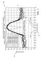
- FIG. 4illustrates a graph 400 of phase values 40 associated with selected range bins (#27 and #29) for each of the detected signals 30 from each of the antennas 16 labeled in this illustration as the receive channels 42 .
- the first signal 30 A from the first antenna 16 Ais processed to determine an amplitude value and a phase value for each of the sampled frequencies associated with the frequency bins 38 a.k.a. range bins.
- one of the range binsis designated as a reference range bin 44 (#28 in this example) because it is associated with a maximum amplitude value 46 .
- the maximum amplitude value 46may be selected based on the maximum value of a combination of all the detected signals 30 by, for example, a non-coherent integration (NCI) of the frequency profile's 32 .
- NCInon-coherent integration
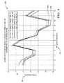
- FIG. 5illustrates a graph 500 of phase differences 50 of each frequency profile at two distinct frequencies, phase bins #27 and #29 in this example. That is, each of the phase differences 50 is the difference in phase values 40 in two of the frequency bins 38 for one of the frequency profiles 32 .
- the single object plot 52 derived from the graph 200shows that there is little change in the phase differences 50 across the receive channels 42
- the two object plot 54 derived from the graph 300show that there is a perceivable change in the phase differences 50 across the receive channels 42 .
- the frequency profiles 32are characterized by values (the amplitude portion 34 and the phase portion 36 ) stored in an array of frequency bins 38 .
- the phase differences 50is determined based on a difference between a first phase value 40 A associated with a first frequency bin 44 A (#27) of the array, and a second phase value 40 B associated with a second frequency bin 44 B (#29) of the array.
- the reference frequency bin 44which is used to select the first frequency bin 44 A and the second frequency bin 44 B, is associated with a maximum amplitude value 46 .
- the first frequency bin 44 Ais adjacent to the reference frequency bin 44 and associated with a lower frequency than the reference frequency bin 44
- the second frequency bin 44 Bis adjacent to the reference frequency bin 44 and associated with a higher frequency than the reference frequency bin 44 .
- the reference frequency bin 44should have sufficient signal strength so noise is not a substantial problem to determine the phase difference between any of the of the frequency bins 44 A, 44 and 44 B.
- the controller 26may be configured to determine a phase slope 56 based on a trend or trend line in the phase differences 50 versus a relative position of each of the antennas 16 that determines the two object plot 54 .
- the controller 26may also be configured to indicate that the target 24 includes more than one object, e.g.
- phase slope 56has a magnitude greater than a slope threshold 58 .
- the phase slope 56 illustratedwould generally be characterized as a negative slope, but positive slopes are possible for other example targets. That is why the magnitude or steepness of the phase slope is coppered to the slope threshold which is also considered in terms of absolute value and not a signed value.
- the value selected for the slope threshold 58may be empirically determined through laboratory and/or field testing.
- the controller 26may be configured to indicate that the target 24 includes more than one object if the phase difference variation 60 is greater than a variation threshold (not shown but understood to be a predetermined value).
- the phase difference variation 60may be determined by, for example, calculating a standard deviation of the phase differences 50 of the two object plot 54 . If the standard deviation is greater than the predetermine value of the variation threshold, then that is an indication that the target 24 includes more than one object.
- the value selected for the variation thresholdmay be empirically determined through laboratory and/or field testing.
- FIG. 6illustrates a non-limiting example of a method 600 of operating a radar system (the system 10 ).
- the method 600is directed to determining if a target 24 detected by the system 10 includes or is made up of more than a single object based on an analysis of phases (e.g. the phase values 40 ) of the detected signals 30 .
- phasese.g. the phase values 40
- Step 610RECEIVE DETECTED SIGNALS, may include a controller 26 receiving the detected signals 30 from a plurality of antennas 16 that are configured to detect a reflected radar signal 20 reflected by an object ( 24 A, 24 B) in a field-of-view 22 of the antennas 16 .
- Each antenna ( 16 A, 16 B) of the plurality of antennasis configured to output a detected signal ( 30 A, 30 B) indicative of the reflected radar signal detected by each of the antennas 16 .
- Step 620DETERMINE TARGET PRESENCE, may include determining if a target 24 is present in the field-of-view 22 based on the detected signals 30 .
- the target 24may be detected by determining the frequency profiles 32 of each detected signals 30 by applying frequency transformation (e.g. Fourier transform) to the time-domain signals from the antennas 16 .
- Frequency transformationstypically provide sampled values of the frequency spectrum arising from the frequency transformation and include an amplitude portion 34 and a phase portion 36 .
- Step 630DETERMINE REFERENCE FREQUENCY, may include detecting a maximum amplitude value 46 of the amplitude portion 34 of the frequency profiles 32 .
- the maximum amplitude value 46may be a maximum or peak value from some composite of the frequency profiles 32 such as a non-coherent integration (NCI) of the frequency profiles 32 .
- NCInon-coherent integration
- Each frequency profilemay be characterized as a range profile or a Doppler profile based on a frequency transformation of a time-domain sample of the detected signal from one antenna, as previously described.
- the frequency profiles 32may be sampled to generate values for frequency bins 38 that represent storage locations for the values.
- a reference frequency bin 44is associated with a maximum amplitude value.
- Step 640DETERMINE FIRST FREQUENCY AND SECOND FREQUENCY, may include determining which of the frequency bins contains an amplitude value greater that some predetermine threshold.
- a first frequency bin 44 A and a second frequency bin 44 Bmay be designated.
- the first frequency bin 44 Amay be adjacent to the reference frequency bin 44 and associated with a lower frequency than the reference frequency bin 44
- the second frequency bin 44 Bmay be adjacent to the reference frequency bin 44 and associated with a higher frequency than the reference frequency bin 44 .
- the reference frequency bin 44may be designated either the first frequency bin 44 A or the second frequency bin 44 B.
- Step 650DETERMINE PHASE DIFFERENCES, may include determining a phase differences 50 of each of the frequency profiles 32 at two distinct frequencies, e.g. frequencies associated with the first frequency bin 44 A and the second frequency bin 44 B.
- Each frequency profileis characterized by values stored in an array of frequency bins 38 , and in this non-limiting example the phase difference is determined based on a difference between a first phase value 40 A associated with the first frequency bin 44 A of the array of receive channels 42 , and a second phase value 40 B associated with a second frequency bin 44 B of the array of receive channels 42 .
- Steps 660 and 670may both be performed, bit it is more likely that only one or the other may be performed.
- the showing of both steps 660 and 670 in method 600should not be construed to mean that it is required that both steps are performed. If either or both of the tests performed by steps 660 and 670 result in the affirmative (YES), the method 600 proceeds to step 680 .
- Step 660may include determining a phase difference variation 60 based on changes in the phase differences 50 versus a relative position of each antenna, which corresponds to the numbering of the receive channels 42 , and determining if the phase difference variation 60 is greater than a variation threshold.
- Step 670may include determining a phase slope 56 based on a trend in the phase differences 50 versus a relative position of each antenna, and determining if the phase slope has a magnitude greater than a slope threshold.
- Step 680INDICATE TARGET INCLUDES MORE THAN ONE OBJECT, may include the controller 26 indicating that the target 24 includes more than one object if the phase difference variation 60 is greater than a variation threshold, and/or indicating that the target 24 includes more than one object if the phase slope 56 has a magnitude greater than a slope threshold 58 .
- the indication that the target 24 includes more than one objectmay, for example, result in the controller initiating other software routines to further examine signals from the antennas for the purpose of classifying or categorizing the multiple objects that constitute the target 24 , or illuminating an indicator to notify an operator of the vehicle that a pedestrian proximate to the vehicle has been detected.
- a radar system(the system 10 ), a controller 26 for the system 10 and a method 600 of operating the system 10 is provided.
- These allinclude an improved way to determine if more than one target is present in the field-of-view 22 where prior attempts may have detected only one target.
- the standard deviation of the phase difference across antenna array elementsindicates a single scattering center or multiple near scattering centers. If multiple near scattering centers are indicated, other near targets detection and discrimination techniques such as the single channel peak detection technique and the space time processing technique can be activated.
- the indicationcan also be used to guide the system 10 to define a Range-Doppler Near Objects Detection zone (RDNOD-zone) of the near scattering centers around the NCI-detection RD-coordinate if there is signal processing resource constraint or if the radar has a relatively small number of antenna-array elements (the antennas 16 ).
- RNOD-zoneRange-Doppler Near Objects Detection zone
- the time-domain fluctuation of standard deviation of the phase differencecan also be used to classify radar on-road object categories.
- This object classifiercan be used by a tracker module to make object guided parameter prediction and enhance object tracking performance. This is particularly relevant for reliably tracking laterally moving objects such as a pedestrian and a bicyclist as the radar sensor is incapable of direct lateral rate measurement.
- the benefits of the system described hereincontributes to, but is not limited to: Enhanced Near Targets identification and Discrimination; Automotive radar Target extent measurement (or imaging); Cross traffic detection and reliable tracking as result of targets discrimination and classification; and optimal usage of limited signal processing resources while improving the performance of near targets identification, discrimination, and tracking.
- This technique described hereinis applicable in many configurations of automotive radar sensor products, and implementation is straight forward with modest increase in signal processing throughput and memory.
Landscapes
- Engineering & Computer Science (AREA)
- Radar, Positioning & Navigation (AREA)
- Remote Sensing (AREA)
- Physics & Mathematics (AREA)
- Computer Networks & Wireless Communication (AREA)
- General Physics & Mathematics (AREA)
- Electromagnetism (AREA)
- Radar Systems Or Details Thereof (AREA)
Abstract
Description
Claims (13)
Priority Applications (4)
| Application Number | Priority Date | Filing Date | Title |
|---|---|---|---|
| US14/491,192US9784820B2 (en) | 2014-09-19 | 2014-09-19 | Radar system with phase based multi-target detection |
| EP15179773.5AEP2998761B1 (en) | 2014-09-19 | 2015-08-05 | Radar system with phase based multi-target detection |
| CN201510541200.2ACN105445734B (en) | 2014-09-19 | 2015-08-28 | Radar system with phase-based multi-target detection |
| US14/854,929US9470777B2 (en) | 2014-09-19 | 2015-09-15 | Radar system for automated vehicle with phase change based target catagorization |
Applications Claiming Priority (1)
| Application Number | Priority Date | Filing Date | Title |
|---|---|---|---|
| US14/491,192US9784820B2 (en) | 2014-09-19 | 2014-09-19 | Radar system with phase based multi-target detection |
Related Child Applications (1)
| Application Number | Title | Priority Date | Filing Date |
|---|---|---|---|
| US14/854,929Continuation-In-PartUS9470777B2 (en) | 2014-09-19 | 2015-09-15 | Radar system for automated vehicle with phase change based target catagorization |
Publications (2)
| Publication Number | Publication Date |
|---|---|
| US20160084941A1 US20160084941A1 (en) | 2016-03-24 |
| US9784820B2true US9784820B2 (en) | 2017-10-10 |
Family
ID=53776484
Family Applications (1)
| Application Number | Title | Priority Date | Filing Date |
|---|---|---|---|
| US14/491,192Active2036-01-08US9784820B2 (en) | 2014-09-19 | 2014-09-19 | Radar system with phase based multi-target detection |
Country Status (3)
| Country | Link |
|---|---|
| US (1) | US9784820B2 (en) |
| EP (1) | EP2998761B1 (en) |
| CN (1) | CN105445734B (en) |
Cited By (9)
| Publication number | Priority date | Publication date | Assignee | Title |
|---|---|---|---|---|
| US20170102453A1 (en)* | 2015-10-07 | 2017-04-13 | Mando Corporation | Radar device for vehicle and method for estimating angle of target using same |
| US10429181B2 (en)* | 2014-02-11 | 2019-10-01 | Vega Grieshaber Kg | Measuring device and method for detecting the characteristics of an object |
| US10826177B2 (en) | 2018-02-27 | 2020-11-03 | Apple Inc. | Electronic devices having phased antenna arrays for performing proximity detection operations |
| US11009603B2 (en)* | 2018-03-16 | 2021-05-18 | Denso Ten Limited | Radar device and radar device control method |
| US20210190900A1 (en)* | 2018-08-10 | 2021-06-24 | HELLA GmbH & Co. KGaA | Method for evaluating overlapping targets |
| US11047972B2 (en)* | 2019-01-28 | 2021-06-29 | Steradian Semiconductors Private Limited | Method, apparatus and device for determining a velocity of an object in a time switched MIMO radar system |
| US11536831B2 (en) | 2020-06-15 | 2022-12-27 | Gm Cruise Holdings Llc | Systems and methods for high velocity resolution high update rate radar for autonomous vehicles |
| US20230055654A1 (en)* | 2019-12-31 | 2023-02-23 | Essence Smartcare Ltd. | State Detection |
| US20230108140A1 (en)* | 2021-10-05 | 2023-04-06 | Infineon Technologies Ag | Radar-based motion classification using one or more time series |
Families Citing this family (87)
| Publication number | Priority date | Publication date | Assignee | Title |
|---|---|---|---|---|
| ES2622928T3 (en)* | 2014-02-19 | 2017-07-07 | Kapsch Trafficcom Ag | Device and procedure for detecting a wheel axle of a vehicle |
| US9470777B2 (en)* | 2014-09-19 | 2016-10-18 | Delphi Technologies, Inc. | Radar system for automated vehicle with phase change based target catagorization |
| EP3144696A1 (en)* | 2015-09-15 | 2017-03-22 | Delphi Technologies, Inc. | Radar system for automated vehicle with phase change based target categorization |
| US9846228B2 (en) | 2016-04-07 | 2017-12-19 | Uhnder, Inc. | Software defined automotive radar systems |
| US10261179B2 (en) | 2016-04-07 | 2019-04-16 | Uhnder, Inc. | Software defined automotive radar |
| WO2017175190A1 (en) | 2016-04-07 | 2017-10-12 | Uhnder, Inc. | Adaptive transmission and interference cancellation for mimo radar |
| CN109073741B (en) | 2016-04-25 | 2019-07-02 | 乌恩德股份有限公司 | Radar sensing system for vehicle and method for mitigating its interference |
| US10573959B2 (en) | 2016-04-25 | 2020-02-25 | Uhnder, Inc. | Vehicle radar system using shaped antenna patterns |
| WO2017187243A1 (en) | 2016-04-25 | 2017-11-02 | Uhnder, Inc. | Vehicular radar sensing system utilizing high rate true random number generator |
| WO2017187242A1 (en) | 2016-04-25 | 2017-11-02 | Uhnder, Inc. | On-demand multi-scan micro doppler for vehicle |
| US9806914B1 (en) | 2016-04-25 | 2017-10-31 | Uhnder, Inc. | Successive signal interference mitigation |
| EP3449272B1 (en) | 2016-04-25 | 2022-11-02 | Uhnder, Inc. | Vehicle radar system with a shared radar and communication system, and method for managing such a system in a vehicle |
| US9791551B1 (en) | 2016-04-25 | 2017-10-17 | Uhnder, Inc. | Vehicular radar system with self-interference cancellation |
| WO2017187304A2 (en) | 2016-04-25 | 2017-11-02 | Uhnder, Inc. | Digital frequency modulated continuous wave radar using handcrafted constant envelope modulation |
| US9791564B1 (en) | 2016-04-25 | 2017-10-17 | Uhnder, Inc. | Adaptive filtering for FMCW interference mitigation in PMCW radar systems |
| JP2017223461A (en)* | 2016-06-13 | 2017-12-21 | パナソニックIpマネジメント株式会社 | Radar device and detection method |
| US9753121B1 (en)* | 2016-06-20 | 2017-09-05 | Uhnder, Inc. | Power control for improved near-far performance of radar systems |
| EP3907529A1 (en)* | 2016-07-01 | 2021-11-10 | Veoneer Sweden AB | A vehicle radar for environmental detection |
| US10641867B2 (en) | 2016-08-15 | 2020-05-05 | Magna Electronics Inc. | Vehicle radar system with shaped radar antennas |
| WO2018051288A1 (en) | 2016-09-16 | 2018-03-22 | Uhnder, Inc. | Virtual radar configuration for 2d array |
| US10222472B2 (en)* | 2016-09-30 | 2019-03-05 | Veoneer Us, Inc. | System and method for detecting heading and velocity of a target object |
| US10481243B2 (en)* | 2016-10-31 | 2019-11-19 | Aptiv Technologies Limited | Automated vehicle radar system with self-calibration |
| KR20180064951A (en)* | 2016-12-06 | 2018-06-15 | 주식회사 비트센싱 | Linear virtual fence system using radar and reflector |
| US10912493B2 (en)* | 2017-01-06 | 2021-02-09 | Panasonic Intellectual Property Management Co., Ltd. | Sensor and method |
| IL250253B (en) | 2017-01-24 | 2021-10-31 | Arbe Robotics Ltd | Method for separating targets and clutter from noise in radar signals |
| US10591591B1 (en)* | 2017-01-31 | 2020-03-17 | L-3 Communications Corp. | Adaptive discovery and correction of phase alignment errors in monopulse antenna systems |
| US10866306B2 (en) | 2017-02-10 | 2020-12-15 | Uhnder, Inc. | Increasing performance of a receive pipeline of a radar with memory optimization |
| WO2018146530A1 (en) | 2017-02-10 | 2018-08-16 | Uhnder, Inc. | Reduced complexity fft-based correlation for automotive radar |
| US11454697B2 (en) | 2017-02-10 | 2022-09-27 | Uhnder, Inc. | Increasing performance of a receive pipeline of a radar with memory optimization |
| DE102018204829A1 (en)* | 2017-04-12 | 2018-10-18 | Ford Global Technologies, Llc | Method and device for analyzing a vehicle environment and vehicle with such a device |
| US10656248B2 (en)* | 2017-05-11 | 2020-05-19 | GM Global Technology Operations LLC | Radar post processing for sidelobe suppression |
| EP3415948B1 (en)* | 2017-06-12 | 2021-11-10 | Aptiv Technologies Limited | A method of determining the de-aliased range rate of a target |
| US10830882B2 (en)* | 2017-06-19 | 2020-11-10 | Ge Aviation Systems, Llc | Methods and apparatus for distributed, multi-node, low-frequency radar systems for degraded visual environments |
| US10690769B2 (en)* | 2017-08-17 | 2020-06-23 | GM Global Technology Operations LLC | Target angle determination using vehicle radar elements with local reference signals |
| US10270498B2 (en)* | 2017-09-11 | 2019-04-23 | Aptiv Technologies Limited | MIMO detector device useful for automated vehicles |
| EP3454080B1 (en)* | 2017-09-12 | 2023-11-01 | Aptiv Technologies Limited | Single scatterer test using phase change |
| EP3454081B1 (en)* | 2017-09-12 | 2023-11-01 | Aptiv Technologies Limited | Single scatterer test using amplitude and a plurality of receive elements |
| CN107665336A (en)* | 2017-09-20 | 2018-02-06 | 厦门理工学院 | Multi-target detection method based on Faster RCNN in intelligent refrigerator |
| EP3460512B1 (en)* | 2017-09-21 | 2022-11-16 | Arriver Software AB | A vehicle radar for environmental detection |
| US10794991B2 (en)* | 2017-11-03 | 2020-10-06 | GM Global Technology Operations LLC | Target detection based on curve detection in range-chirp map |
| IL255982A (en) | 2017-11-29 | 2018-01-31 | Arbe Robotics Ltd | Detection, mitigation and avoidance of mutual interference between automotive radars |
| DE102017129149A1 (en)* | 2017-12-07 | 2019-06-13 | Valeo Schalter Und Sensoren Gmbh | Method for determining at least one object information of at least one target object, which is detected by a radar system, in particular of a vehicle, radar system and driver assistance system |
| US11105890B2 (en) | 2017-12-14 | 2021-08-31 | Uhnder, Inc. | Frequency modulated signal cancellation in variable power mode for radar applications |
| US10935651B2 (en)* | 2017-12-15 | 2021-03-02 | Google Llc | Radar angular ambiguity resolution |
| US12386029B2 (en) | 2018-01-29 | 2025-08-12 | Robert Bosch Gmbh | Millimeter wave automotive radar systems |
| DE102018102816B3 (en)* | 2018-02-08 | 2019-07-04 | Infineon Technologies Ag | RADAR WITH PHASE CORRECTION |
| US11199611B2 (en) | 2018-02-20 | 2021-12-14 | Magna Electronics Inc. | Vehicle radar system with T-shaped slot antennas |
| EP3546978B1 (en)* | 2018-03-29 | 2021-12-08 | Aptiv Technologies Limited | Method for testing a target object as single point scattering center |
| US11275170B2 (en)* | 2018-04-06 | 2022-03-15 | Electromagnetic Systems, Inc. | Use of dual processing channels for stationary and moving objects illuminated by radar |
| IL259190A (en) | 2018-05-07 | 2018-06-28 | Arbe Robotics Ltd | System and method of fmcw time multiplexed mimo imaging radar using multi-band chirps |
| US10482768B1 (en)* | 2018-05-08 | 2019-11-19 | Denso International America, Inc. | Vehicle function impairment detection |
| IL260694A (en) | 2018-07-19 | 2019-01-31 | Arbe Robotics Ltd | Apparatus and method of two-stage signal processing in a radar system |
| IL260695A (en) | 2018-07-19 | 2019-01-31 | Arbe Robotics Ltd | Apparatus and method of eliminating settling time delays in a radar system |
| IL260696A (en) | 2018-07-19 | 2019-01-31 | Arbe Robotics Ltd | Apparatus and method of rf built in self-test (rfbist) in a radar system |
| IL261636A (en) | 2018-09-05 | 2018-10-31 | Arbe Robotics Ltd | Skewed mimo antenna array for use in automotive imaging radar |
| CN109222983A (en)* | 2018-09-13 | 2019-01-18 | 上海宇佑船舶科技有限公司 | A kind of form monitoring method based on nanometer wave technology |
| US11474225B2 (en) | 2018-11-09 | 2022-10-18 | Uhnder, Inc. | Pulse digital mimo radar system |
| US10969466B2 (en)* | 2018-11-13 | 2021-04-06 | GM Global Technology Operations LLC | Sliding window integration scheme for object detection in a radar system |
| KR102733511B1 (en)* | 2018-12-04 | 2024-11-25 | 삼성전자주식회사 | Method and device to process radar data |
| CN109521417B (en)* | 2018-12-07 | 2023-01-03 | 哈尔滨工程大学 | Multi-target detection calculation method based on FMCW radar waveform |
| US11885874B2 (en)* | 2018-12-19 | 2024-01-30 | Semiconductor Components Industries, Llc | Acoustic distance measuring circuit and method for low frequency modulated (LFM) chirp signals |
| CN109493637B (en)* | 2018-12-26 | 2021-12-03 | 武汉拓宝科技股份有限公司 | Parking space state detection method |
| WO2020183392A1 (en) | 2019-03-12 | 2020-09-17 | Uhnder, Inc. | Method and apparatus for mitigation of low frequency noise in radar systems |
| CN110286354B (en)* | 2019-04-23 | 2021-10-15 | 中国人民解放军63921部队 | Multi-target detection and discrimination method, apparatus and computer-readable storage medium |
| US11300655B2 (en)* | 2019-09-05 | 2022-04-12 | GM Global Technology Operations LLC | Object detection using radar |
| CN110888134B (en)* | 2019-11-04 | 2023-07-18 | 电子科技大学 | A non-cooperative and cooperative integrated airport surface surveillance system |
| CN115087883A (en)* | 2019-11-25 | 2022-09-20 | 伦威夫公司 | Automobile radar based on gradient refractive index lens |
| IL271269A (en) | 2019-12-09 | 2021-06-30 | Arbe Robotics Ltd | Radome for automotive radar patch antenna |
| CN111175738B (en)* | 2020-01-08 | 2022-09-30 | 中国船舶重工集团公司第七二四研究所 | Multi-model membership control-based rapid navigation method for phased array radar target |
| CN113096791B (en)* | 2020-01-08 | 2024-06-04 | 富士通株式会社 | Personnel identification device, method and system based on wireless signal |
| US11953615B2 (en) | 2020-01-13 | 2024-04-09 | Uhnder Inc. | Method and system for antenna array calibration for cross-coupling and gain/phase variations in radar systems |
| CN112578353B (en)* | 2020-02-28 | 2024-10-29 | 加特兰微电子科技(上海)有限公司 | Device and method for measuring angle of target, sensor and equipment |
| KR102797867B1 (en)* | 2020-05-08 | 2025-04-21 | 주식회사 에이치엘클레무브 | Radar sensor control apparatus and method |
| US12013484B2 (en)* | 2020-05-20 | 2024-06-18 | Infineon Technologies Ag | Radar receiving system and method for compensating a phase error between radar receiving circuits |
| US11555920B2 (en)* | 2020-10-28 | 2023-01-17 | GM Global Technology Operations LLC | Estimating vehicle velocity using radar data |
| IL278587A (en) | 2020-11-09 | 2022-06-01 | Arbe Robotics Ltd | Estimating an efficient direction of arrival using a low degree approximation |
| EP4012438A1 (en)* | 2020-12-10 | 2022-06-15 | Aptiv Technologies Limited | Radar device |
| WO2022165211A1 (en)* | 2021-01-29 | 2022-08-04 | Indie Semiconductor, Inc. | Method for detecting objects in automotive-grade radar signals |
| CN113093137B (en)* | 2021-04-02 | 2022-08-12 | 电子科技大学 | A Clutter Suppression Method Based on Optimal Frequency Offset Estimation for FDA-MIMO Radar |
| CN112990170B (en)* | 2021-05-20 | 2021-07-16 | 成都市克莱微波科技有限公司 | Phased array radar target identification method and system, electronic device and medium |
| CN113341762B (en)* | 2021-05-25 | 2022-12-13 | 上海机电工程研究所 | Composite target simulation method and system in semi-physical simulation system |
| CN118202274A (en)* | 2021-11-19 | 2024-06-14 | 华为技术有限公司 | Radar system, method and vehicle for detecting pedestrians |
| CN114400443B (en)* | 2021-12-10 | 2025-06-24 | 福瑞泰克智能系统有限公司 | Dual-peak antenna assembly for vehicle, method for determining preparation parameters, automotive radar and vehicle |
| CN116413676A (en)* | 2021-12-29 | 2023-07-11 | 华为技术有限公司 | A laser radar sending device, detection system and detection method |
| CN115436929B (en)* | 2022-09-05 | 2025-07-04 | 北京航空航天大学 | An extended method of sawtooth wave radar speed measurement based on amplitude ratio angle measurement mode |
| CN116679301B (en)* | 2023-07-28 | 2023-10-20 | 西安电子科技大学 | Method for rapidly reconstructing target range profile of broadband radar in super-resolution mode |
| CN116965915B (en)* | 2023-08-03 | 2024-11-19 | 天津市鹰泰利安康医疗科技有限责任公司 | Heart three-dimensional mapping method and system based on ultrasonic ranging |
Citations (33)
| Publication number | Priority date | Publication date | Assignee | Title |
|---|---|---|---|---|
| US3952303A (en)* | 1973-02-15 | 1976-04-20 | Matsushita Electric Industrial Co., Ltd. | Doppler radar for forecasting collision |
| US3978481A (en)* | 1974-06-17 | 1976-08-31 | Merlin A. Pierson | Anti-collision vehicular radar system |
| GB2175767A (en) | 1985-05-28 | 1986-12-03 | Standard Telephones Cables Ltd | Radar systems |
| US4630051A (en)* | 1985-03-01 | 1986-12-16 | Holodyne Ltd., 1986 | Imaging doppler interferometer |
| US5093649A (en)* | 1990-08-28 | 1992-03-03 | The Boeing Company | Bessel beam radar system using sequential spatial modulation |
| US5302956A (en)* | 1992-08-14 | 1994-04-12 | Vorad Safety Systems, Inc. | Multi-frequency, multi-target vehicular radar system using digital signal processing |
| US6337656B1 (en)* | 1999-06-03 | 2002-01-08 | Denso Corporation | Monopulse radar apparatus |
| US6538599B1 (en)* | 2001-11-16 | 2003-03-25 | Raytheon Company | Noncoherent gain enhancement technique for non-stationary targets |
| US6703967B1 (en)* | 2000-01-28 | 2004-03-09 | Hitachi Ltd. | Distance measuring device |
| US20050156780A1 (en)* | 2004-01-16 | 2005-07-21 | Ghz Tr Corporation | Methods and apparatus for automotive radar sensors |
| US6924762B2 (en)* | 2003-05-15 | 2005-08-02 | Denso Corporation | Radar designed to acquire radar data with high accuracy |
| EP1580572A1 (en) | 2004-03-22 | 2005-09-28 | Fujitsu Ten Limited | Digital beamforming radar apparatus |
| US7301496B2 (en)* | 2004-08-04 | 2007-11-27 | Fujitsu Ten Limited | Radar apparatus |
| US20080165049A1 (en)* | 2007-01-09 | 2008-07-10 | Mitsubishi Electronic Corporation | Radar device |
| US7667637B2 (en)* | 2004-04-05 | 2010-02-23 | Weibel Scientific A/S | System and method for radar detection of an object |
| US20100075618A1 (en)* | 2008-09-19 | 2010-03-25 | Fujitsu Ten Limited | Signal processing apparatus and radar apparatus |
| US7791528B2 (en)* | 2008-11-24 | 2010-09-07 | Autoliv Asp, Inc. | Method and apparatus for radar signal processing |
| US8054216B2 (en)* | 2008-01-29 | 2011-11-08 | Fujitsu Ten Limited | Radar device and target angle detection method |
| US8085184B2 (en)* | 2008-06-12 | 2011-12-27 | Mitsubishi Electric Corporation | Radar device and processing method therefor |
| US8446312B2 (en)* | 2007-12-25 | 2013-05-21 | Honda Elesys Co., Ltd. | Electronic scanning type radar device, estimation method of direction of reception wave, and program estimating direction of reception wave |
| US20130127655A1 (en)* | 2011-04-15 | 2013-05-23 | Panasonic Corporation | Radar device |
| US8558733B2 (en)* | 2010-03-15 | 2013-10-15 | Honda Elesys Co., Ltd. | Radar apparatus and computer program |
| US8779969B2 (en)* | 2011-04-21 | 2014-07-15 | Denso Corporation | Radar device for detecting azimuth of target |
| US8816902B2 (en)* | 2011-05-17 | 2014-08-26 | Fujitsu Ten Limited | Radar apparatus |
| US20140247180A1 (en) | 2012-12-06 | 2014-09-04 | Fujitsu Ten Limited | Radar apparatus and signal processing method |
| US8847815B2 (en)* | 2010-12-22 | 2014-09-30 | Honda Elesys Co., Ltd. | Electronic scanning radar apparatus, received wave direction estimating method, and received wave direction estimating program |
| US8866668B2 (en)* | 2011-11-02 | 2014-10-21 | Denso Corporation | Radar apparatus with different operation modes |
| US8907840B2 (en)* | 2011-02-04 | 2014-12-09 | Honda Elesys Co., Ltd. | Electronic scanning radar apparatus, received wave direction estimating method, and received wave direction estimating program |
| US8976058B2 (en)* | 2012-02-13 | 2015-03-10 | Denso Corporation | Vechicle-mounted radar apparatus |
| US8994582B2 (en)* | 2011-03-23 | 2015-03-31 | Fujitsu Ten Limited | Calculation device for radar apparatus, radar apparatus and calculation method |
| US9097796B2 (en)* | 2010-11-12 | 2015-08-04 | Denso Corporation | Radar apparatus |
| US9383440B2 (en)* | 2012-10-30 | 2016-07-05 | Fujitsu Ten Limited | Radar apparatus and signal processing method |
| US9400325B2 (en)* | 2014-11-26 | 2016-07-26 | Valeo Radar Systems, Inc. | Method and apparatus for increasing angular resolution in an automotive radar system |
Family Cites Families (1)
| Publication number | Priority date | Publication date | Assignee | Title |
|---|---|---|---|---|
| CN102707266B (en)* | 2012-05-24 | 2014-06-04 | 北京理工大学 | Radar with anti-interference and multi-target identification functions and detection method thereof |
- 2014
- 2014-09-19USUS14/491,192patent/US9784820B2/enactiveActive
- 2015
- 2015-08-05EPEP15179773.5Apatent/EP2998761B1/enactiveActive
- 2015-08-28CNCN201510541200.2Apatent/CN105445734B/enactiveActive
Patent Citations (34)
| Publication number | Priority date | Publication date | Assignee | Title |
|---|---|---|---|---|
| US3952303A (en)* | 1973-02-15 | 1976-04-20 | Matsushita Electric Industrial Co., Ltd. | Doppler radar for forecasting collision |
| US3978481A (en)* | 1974-06-17 | 1976-08-31 | Merlin A. Pierson | Anti-collision vehicular radar system |
| US4630051A (en)* | 1985-03-01 | 1986-12-16 | Holodyne Ltd., 1986 | Imaging doppler interferometer |
| GB2175767A (en) | 1985-05-28 | 1986-12-03 | Standard Telephones Cables Ltd | Radar systems |
| US5093649A (en)* | 1990-08-28 | 1992-03-03 | The Boeing Company | Bessel beam radar system using sequential spatial modulation |
| US5302956A (en)* | 1992-08-14 | 1994-04-12 | Vorad Safety Systems, Inc. | Multi-frequency, multi-target vehicular radar system using digital signal processing |
| US6337656B1 (en)* | 1999-06-03 | 2002-01-08 | Denso Corporation | Monopulse radar apparatus |
| US6703967B1 (en)* | 2000-01-28 | 2004-03-09 | Hitachi Ltd. | Distance measuring device |
| US6538599B1 (en)* | 2001-11-16 | 2003-03-25 | Raytheon Company | Noncoherent gain enhancement technique for non-stationary targets |
| US6924762B2 (en)* | 2003-05-15 | 2005-08-02 | Denso Corporation | Radar designed to acquire radar data with high accuracy |
| US20050156780A1 (en)* | 2004-01-16 | 2005-07-21 | Ghz Tr Corporation | Methods and apparatus for automotive radar sensors |
| EP1580572A1 (en) | 2004-03-22 | 2005-09-28 | Fujitsu Ten Limited | Digital beamforming radar apparatus |
| US7190305B2 (en)* | 2004-03-22 | 2007-03-13 | Fujitsu Ten Limited | Radar apparatus |
| US7667637B2 (en)* | 2004-04-05 | 2010-02-23 | Weibel Scientific A/S | System and method for radar detection of an object |
| US7301496B2 (en)* | 2004-08-04 | 2007-11-27 | Fujitsu Ten Limited | Radar apparatus |
| US20080165049A1 (en)* | 2007-01-09 | 2008-07-10 | Mitsubishi Electronic Corporation | Radar device |
| US8446312B2 (en)* | 2007-12-25 | 2013-05-21 | Honda Elesys Co., Ltd. | Electronic scanning type radar device, estimation method of direction of reception wave, and program estimating direction of reception wave |
| US8054216B2 (en)* | 2008-01-29 | 2011-11-08 | Fujitsu Ten Limited | Radar device and target angle detection method |
| US8085184B2 (en)* | 2008-06-12 | 2011-12-27 | Mitsubishi Electric Corporation | Radar device and processing method therefor |
| US20100075618A1 (en)* | 2008-09-19 | 2010-03-25 | Fujitsu Ten Limited | Signal processing apparatus and radar apparatus |
| US7791528B2 (en)* | 2008-11-24 | 2010-09-07 | Autoliv Asp, Inc. | Method and apparatus for radar signal processing |
| US8558733B2 (en)* | 2010-03-15 | 2013-10-15 | Honda Elesys Co., Ltd. | Radar apparatus and computer program |
| US9097796B2 (en)* | 2010-11-12 | 2015-08-04 | Denso Corporation | Radar apparatus |
| US8847815B2 (en)* | 2010-12-22 | 2014-09-30 | Honda Elesys Co., Ltd. | Electronic scanning radar apparatus, received wave direction estimating method, and received wave direction estimating program |
| US8907840B2 (en)* | 2011-02-04 | 2014-12-09 | Honda Elesys Co., Ltd. | Electronic scanning radar apparatus, received wave direction estimating method, and received wave direction estimating program |
| US8994582B2 (en)* | 2011-03-23 | 2015-03-31 | Fujitsu Ten Limited | Calculation device for radar apparatus, radar apparatus and calculation method |
| US20130127655A1 (en)* | 2011-04-15 | 2013-05-23 | Panasonic Corporation | Radar device |
| US8779969B2 (en)* | 2011-04-21 | 2014-07-15 | Denso Corporation | Radar device for detecting azimuth of target |
| US8816902B2 (en)* | 2011-05-17 | 2014-08-26 | Fujitsu Ten Limited | Radar apparatus |
| US8866668B2 (en)* | 2011-11-02 | 2014-10-21 | Denso Corporation | Radar apparatus with different operation modes |
| US8976058B2 (en)* | 2012-02-13 | 2015-03-10 | Denso Corporation | Vechicle-mounted radar apparatus |
| US9383440B2 (en)* | 2012-10-30 | 2016-07-05 | Fujitsu Ten Limited | Radar apparatus and signal processing method |
| US20140247180A1 (en) | 2012-12-06 | 2014-09-04 | Fujitsu Ten Limited | Radar apparatus and signal processing method |
| US9400325B2 (en)* | 2014-11-26 | 2016-07-26 | Valeo Radar Systems, Inc. | Method and apparatus for increasing angular resolution in an automotive radar system |
Cited By (12)
| Publication number | Priority date | Publication date | Assignee | Title |
|---|---|---|---|---|
| US10429181B2 (en)* | 2014-02-11 | 2019-10-01 | Vega Grieshaber Kg | Measuring device and method for detecting the characteristics of an object |
| US20170102453A1 (en)* | 2015-10-07 | 2017-04-13 | Mando Corporation | Radar device for vehicle and method for estimating angle of target using same |
| US10732273B2 (en)* | 2015-10-07 | 2020-08-04 | Mando Corporation | Radar device for vehicle and method for estimating angle of target using same |
| US10826177B2 (en) | 2018-02-27 | 2020-11-03 | Apple Inc. | Electronic devices having phased antenna arrays for performing proximity detection operations |
| US11009603B2 (en)* | 2018-03-16 | 2021-05-18 | Denso Ten Limited | Radar device and radar device control method |
| US20210190900A1 (en)* | 2018-08-10 | 2021-06-24 | HELLA GmbH & Co. KGaA | Method for evaluating overlapping targets |
| US12241991B2 (en)* | 2018-08-10 | 2025-03-04 | HELLA GmbH & Co. KGaA | Method for evaluating overlapping targets |
| US11047972B2 (en)* | 2019-01-28 | 2021-06-29 | Steradian Semiconductors Private Limited | Method, apparatus and device for determining a velocity of an object in a time switched MIMO radar system |
| US20230055654A1 (en)* | 2019-12-31 | 2023-02-23 | Essence Smartcare Ltd. | State Detection |
| US11536831B2 (en) | 2020-06-15 | 2022-12-27 | Gm Cruise Holdings Llc | Systems and methods for high velocity resolution high update rate radar for autonomous vehicles |
| US12123946B2 (en) | 2020-06-15 | 2024-10-22 | Gm Cruise Holdings Llc | Systems and methods for high velocity resolution high update rate radar for autonomous vehicles |
| US20230108140A1 (en)* | 2021-10-05 | 2023-04-06 | Infineon Technologies Ag | Radar-based motion classification using one or more time series |
Also Published As
| Publication number | Publication date |
|---|---|
| CN105445734B (en) | 2019-10-15 |
| EP2998761B1 (en) | 2020-01-01 |
| EP2998761A1 (en) | 2016-03-23 |
| CN105445734A (en) | 2016-03-30 |
| US20160084941A1 (en) | 2016-03-24 |
Similar Documents
| Publication | Publication Date | Title |
|---|---|---|
| US9784820B2 (en) | Radar system with phase based multi-target detection | |
| US9470777B2 (en) | Radar system for automated vehicle with phase change based target catagorization | |
| EP2944977B1 (en) | Radar system with improved multi-target discrimination | |
| EP3144696A1 (en) | Radar system for automated vehicle with phase change based target categorization | |
| US10481244B2 (en) | Method for classifying an object in an area surrounding a motor vehicle, driver assistance system and motor vehicle | |
| US11391818B2 (en) | System for using FMCW and CW to detect a moving object | |
| US10473760B2 (en) | Radar device and vertical axis-misalignment detecting method | |
| US9140788B2 (en) | Ascertaining an indicator for the drive-over capability of an object | |
| CN109752699B (en) | Target detection based on curve detection in distance-chirp graph | |
| US10393862B2 (en) | Trailer estimation with elevation enhanced sensing | |
| US10429494B2 (en) | Method and apparatus for detecting target object | |
| US8581774B2 (en) | Method for detecting precipitation using a radar locating device for motor vehicles | |
| US20130314272A1 (en) | Detection of radar objects with the aid of a radar sensor of a motor vehicle | |
| US8836572B2 (en) | Method for detecting precipitation using a radar sensor system for motor vehicles | |
| US20120268317A1 (en) | FMCW Radar Sensor System Having a Device for Detecting a Radome Coating | |
| EP3460506A1 (en) | Method for monitoring the performance range of an automotive radar system | |
| US6943727B2 (en) | Length measurement with radar | |
| US20180321377A1 (en) | Method for capturing a surrounding region of a motor vehicle with object classification, control device, driver assistance system and motor vehicle | |
| US11333754B2 (en) | Detection of parking row orientation | |
| KR20180064127A (en) | Method for detecting target object and apparatus thereof | |
| Lim et al. | Rejection of road clutter using mean-variance method with OS-CFAR for automotive applications |
Legal Events
| Date | Code | Title | Description |
|---|---|---|---|
| AS | Assignment | Owner name:DELPHI TECHNOLOGIES, INC., MICHIGAN Free format text:ASSIGNMENT OF ASSIGNORS INTEREST;ASSIGNOR:ARAGE, ALEBEL HASSEN;REEL/FRAME:033778/0004 Effective date:20140919 | |
| STCF | Information on status: patent grant | Free format text:PATENTED CASE | |
| AS | Assignment | Owner name:APTIV TECHNOLOGIES LIMITED, BARBADOS Free format text:ASSIGNMENT OF ASSIGNORS INTEREST;ASSIGNOR:DELPHI TECHNOLOGIES INC.;REEL/FRAME:047143/0874 Effective date:20180101 | |
| MAFP | Maintenance fee payment | Free format text:PAYMENT OF MAINTENANCE FEE, 4TH YEAR, LARGE ENTITY (ORIGINAL EVENT CODE: M1551); ENTITY STATUS OF PATENT OWNER: LARGE ENTITY Year of fee payment:4 | |
| AS | Assignment | Owner name:APTIV TECHNOLOGIES (2) S.A R.L., LUXEMBOURG Free format text:ENTITY CONVERSION;ASSIGNOR:APTIV TECHNOLOGIES LIMITED;REEL/FRAME:066746/0001 Effective date:20230818 Owner name:APTIV MANUFACTURING MANAGEMENT SERVICES S.A R.L., LUXEMBOURG Free format text:MERGER;ASSIGNOR:APTIV TECHNOLOGIES (2) S.A R.L.;REEL/FRAME:066566/0173 Effective date:20231005 Owner name:APTIV TECHNOLOGIES AG, SWITZERLAND Free format text:ASSIGNMENT OF ASSIGNORS INTEREST;ASSIGNOR:APTIV MANUFACTURING MANAGEMENT SERVICES S.A R.L.;REEL/FRAME:066551/0219 Effective date:20231006 | |
| MAFP | Maintenance fee payment | Free format text:PAYMENT OF MAINTENANCE FEE, 8TH YEAR, LARGE ENTITY (ORIGINAL EVENT CODE: M1552); ENTITY STATUS OF PATENT OWNER: LARGE ENTITY Year of fee payment:8 |