US9784181B2 - Gas turbine engine architecture with low pressure compressor hub between high and low rotor thrust bearings - Google Patents
Gas turbine engine architecture with low pressure compressor hub between high and low rotor thrust bearingsDownload PDFInfo
- Publication number
- US9784181B2 US9784181B2US13/304,053US201113304053AUS9784181B2US 9784181 B2US9784181 B2US 9784181B2US 201113304053 AUS201113304053 AUS 201113304053AUS 9784181 B2US9784181 B2US 9784181B2
- Authority
- US
- United States
- Prior art keywords
- pressure compressor
- bearing system
- low pressure
- gas turbine
- turbine engine
- Prior art date
- Legal status (The legal status is an assumption and is not a legal conclusion. Google has not performed a legal analysis and makes no representation as to the accuracy of the status listed.)
- Active, expires
Links
- 230000008878couplingEffects0.000claimsdescription14
- 238000010168coupling processMethods0.000claimsdescription14
- 238000005859coupling reactionMethods0.000claimsdescription14
- 238000011144upstream manufacturingMethods0.000claims6
- 230000036316preloadEffects0.000description8
- 230000008901benefitEffects0.000description6
- 238000004519manufacturing processMethods0.000description5
- 230000003068static effectEffects0.000description4
- 125000006850spacer groupChemical group0.000description3
- 230000005540biological transmissionEffects0.000description2
- 238000010586diagramMethods0.000description2
- 230000009467reductionEffects0.000description2
- OKTJSMMVPCPJKN-UHFFFAOYSA-NCarbonChemical compound[C]OKTJSMMVPCPJKN-UHFFFAOYSA-N0.000description1
- 238000010521absorption reactionMethods0.000description1
- 238000005452bendingMethods0.000description1
- 229910052799carbonInorganic materials0.000description1
- 238000004891communicationMethods0.000description1
- 230000006835compressionEffects0.000description1
- 238000007906compressionMethods0.000description1
- 239000000446fuelSubstances0.000description1
- 230000020169heat generationEffects0.000description1
- 238000005461lubricationMethods0.000description1
- 238000012986modificationMethods0.000description1
- 230000004048modificationEffects0.000description1
- 238000010248power generationMethods0.000description1
- 230000004044responseEffects0.000description1
- 230000000717retained effectEffects0.000description1
- 238000007789sealingMethods0.000description1
- 238000005204segregationMethods0.000description1
- 238000004513sizingMethods0.000description1
- 229910001220stainless steelInorganic materials0.000description1
- 239000010935stainless steelSubstances0.000description1
- 230000007704transitionEffects0.000description1
Images


Classifications
- F—MECHANICAL ENGINEERING; LIGHTING; HEATING; WEAPONS; BLASTING
- F02—COMBUSTION ENGINES; HOT-GAS OR COMBUSTION-PRODUCT ENGINE PLANTS
- F02C—GAS-TURBINE PLANTS; AIR INTAKES FOR JET-PROPULSION PLANTS; CONTROLLING FUEL SUPPLY IN AIR-BREATHING JET-PROPULSION PLANTS
- F02C3/00—Gas-turbine plants characterised by the use of combustion products as the working fluid
- F02C3/04—Gas-turbine plants characterised by the use of combustion products as the working fluid having a turbine driving a compressor
- F02C3/107—Gas-turbine plants characterised by the use of combustion products as the working fluid having a turbine driving a compressor with two or more rotors connected by power transmission
- F—MECHANICAL ENGINEERING; LIGHTING; HEATING; WEAPONS; BLASTING
- F01—MACHINES OR ENGINES IN GENERAL; ENGINE PLANTS IN GENERAL; STEAM ENGINES
- F01D—NON-POSITIVE DISPLACEMENT MACHINES OR ENGINES, e.g. STEAM TURBINES
- F01D25/00—Component parts, details, or accessories, not provided for in, or of interest apart from, other groups
- F01D25/16—Arrangement of bearings; Supporting or mounting bearings in casings
- F01D25/162—Bearing supports
- F—MECHANICAL ENGINEERING; LIGHTING; HEATING; WEAPONS; BLASTING
- F02—COMBUSTION ENGINES; HOT-GAS OR COMBUSTION-PRODUCT ENGINE PLANTS
- F02C—GAS-TURBINE PLANTS; AIR INTAKES FOR JET-PROPULSION PLANTS; CONTROLLING FUEL SUPPLY IN AIR-BREATHING JET-PROPULSION PLANTS
- F02C7/00—Features, components parts, details or accessories, not provided for in, or of interest apart form groups F02C1/00 - F02C6/00; Air intakes for jet-propulsion plants
- F02C7/06—Arrangements of bearings; Lubricating
- F—MECHANICAL ENGINEERING; LIGHTING; HEATING; WEAPONS; BLASTING
- F02—COMBUSTION ENGINES; HOT-GAS OR COMBUSTION-PRODUCT ENGINE PLANTS
- F02K—JET-PROPULSION PLANTS
- F02K3/00—Plants including a gas turbine driving a compressor or a ducted fan
- F02K3/02—Plants including a gas turbine driving a compressor or a ducted fan in which part of the working fluid by-passes the turbine and combustion chamber
- F02K3/04—Plants including a gas turbine driving a compressor or a ducted fan in which part of the working fluid by-passes the turbine and combustion chamber the plant including ducted fans, i.e. fans with high volume, low pressure outputs, for augmenting the jet thrust, e.g. of double-flow type
- F02K3/06—Plants including a gas turbine driving a compressor or a ducted fan in which part of the working fluid by-passes the turbine and combustion chamber the plant including ducted fans, i.e. fans with high volume, low pressure outputs, for augmenting the jet thrust, e.g. of double-flow type with front fan
- F—MECHANICAL ENGINEERING; LIGHTING; HEATING; WEAPONS; BLASTING
- F16—ENGINEERING ELEMENTS AND UNITS; GENERAL MEASURES FOR PRODUCING AND MAINTAINING EFFECTIVE FUNCTIONING OF MACHINES OR INSTALLATIONS; THERMAL INSULATION IN GENERAL
- F16C—SHAFTS; FLEXIBLE SHAFTS; ELEMENTS OR CRANKSHAFT MECHANISMS; ROTARY BODIES OTHER THAN GEARING ELEMENTS; BEARINGS
- F16C25/00—Bearings for exclusively rotary movement adjustable for wear or play
- F16C25/06—Ball or roller bearings
- F16C25/08—Ball or roller bearings self-adjusting
- F16C25/083—Ball or roller bearings self-adjusting with resilient means acting axially on a race ring to preload the bearing
- F—MECHANICAL ENGINEERING; LIGHTING; HEATING; WEAPONS; BLASTING
- F05—INDEXING SCHEMES RELATING TO ENGINES OR PUMPS IN VARIOUS SUBCLASSES OF CLASSES F01-F04
- F05D—INDEXING SCHEME FOR ASPECTS RELATING TO NON-POSITIVE-DISPLACEMENT MACHINES OR ENGINES, GAS-TURBINES OR JET-PROPULSION PLANTS
- F05D2230/00—Manufacture
- F05D2230/72—Maintenance
- F—MECHANICAL ENGINEERING; LIGHTING; HEATING; WEAPONS; BLASTING
- F05—INDEXING SCHEMES RELATING TO ENGINES OR PUMPS IN VARIOUS SUBCLASSES OF CLASSES F01-F04
- F05D—INDEXING SCHEME FOR ASPECTS RELATING TO NON-POSITIVE-DISPLACEMENT MACHINES OR ENGINES, GAS-TURBINES OR JET-PROPULSION PLANTS
- F05D2230/00—Manufacture
- F05D2230/80—Repairing, retrofitting or upgrading methods
- F—MECHANICAL ENGINEERING; LIGHTING; HEATING; WEAPONS; BLASTING
- F05—INDEXING SCHEMES RELATING TO ENGINES OR PUMPS IN VARIOUS SUBCLASSES OF CLASSES F01-F04
- F05D—INDEXING SCHEME FOR ASPECTS RELATING TO NON-POSITIVE-DISPLACEMENT MACHINES OR ENGINES, GAS-TURBINES OR JET-PROPULSION PLANTS
- F05D2250/00—Geometry
- F05D2250/20—Three-dimensional
- F05D2250/23—Three-dimensional prismatic
- F05D2250/232—Three-dimensional prismatic conical
- F—MECHANICAL ENGINEERING; LIGHTING; HEATING; WEAPONS; BLASTING
- F05—INDEXING SCHEMES RELATING TO ENGINES OR PUMPS IN VARIOUS SUBCLASSES OF CLASSES F01-F04
- F05D—INDEXING SCHEME FOR ASPECTS RELATING TO NON-POSITIVE-DISPLACEMENT MACHINES OR ENGINES, GAS-TURBINES OR JET-PROPULSION PLANTS
- F05D2260/00—Function
- F05D2260/30—Retaining components in desired mutual position
- F05D2260/38—Retaining components in desired mutual position by a spring, i.e. spring loaded or biased towards a certain position
- F—MECHANICAL ENGINEERING; LIGHTING; HEATING; WEAPONS; BLASTING
- F05—INDEXING SCHEMES RELATING TO ENGINES OR PUMPS IN VARIOUS SUBCLASSES OF CLASSES F01-F04
- F05D—INDEXING SCHEME FOR ASPECTS RELATING TO NON-POSITIVE-DISPLACEMENT MACHINES OR ENGINES, GAS-TURBINES OR JET-PROPULSION PLANTS
- F05D2260/00—Function
- F05D2260/40—Transmission of power
- F05D2260/403—Transmission of power through the shape of the drive components
- F05D2260/4031—Transmission of power through the shape of the drive components as in toothed gearing
- F05D2260/40311—Transmission of power through the shape of the drive components as in toothed gearing of the epicyclical, planetary or differential type
- F—MECHANICAL ENGINEERING; LIGHTING; HEATING; WEAPONS; BLASTING
- F16—ENGINEERING ELEMENTS AND UNITS; GENERAL MEASURES FOR PRODUCING AND MAINTAINING EFFECTIVE FUNCTIONING OF MACHINES OR INSTALLATIONS; THERMAL INSULATION IN GENERAL
- F16C—SHAFTS; FLEXIBLE SHAFTS; ELEMENTS OR CRANKSHAFT MECHANISMS; ROTARY BODIES OTHER THAN GEARING ELEMENTS; BEARINGS
- F16C19/00—Bearings with rolling contact, for exclusively rotary movement
- F16C19/22—Bearings with rolling contact, for exclusively rotary movement with bearing rollers essentially of the same size in one or more circular rows, e.g. needle bearings
- F16C19/34—Bearings with rolling contact, for exclusively rotary movement with bearing rollers essentially of the same size in one or more circular rows, e.g. needle bearings for both radial and axial load
- F16C19/36—Bearings with rolling contact, for exclusively rotary movement with bearing rollers essentially of the same size in one or more circular rows, e.g. needle bearings for both radial and axial load with a single row of rollers
- F16C19/364—Bearings with rolling contact, for exclusively rotary movement with bearing rollers essentially of the same size in one or more circular rows, e.g. needle bearings for both radial and axial load with a single row of rollers with tapered rollers, i.e. rollers having essentially the shape of a truncated cone
- F—MECHANICAL ENGINEERING; LIGHTING; HEATING; WEAPONS; BLASTING
- F16—ENGINEERING ELEMENTS AND UNITS; GENERAL MEASURES FOR PRODUCING AND MAINTAINING EFFECTIVE FUNCTIONING OF MACHINES OR INSTALLATIONS; THERMAL INSULATION IN GENERAL
- F16C—SHAFTS; FLEXIBLE SHAFTS; ELEMENTS OR CRANKSHAFT MECHANISMS; ROTARY BODIES OTHER THAN GEARING ELEMENTS; BEARINGS
- F16C19/00—Bearings with rolling contact, for exclusively rotary movement
- F16C19/54—Systems consisting of a plurality of bearings with rolling friction
- F16C19/546—Systems with spaced apart rolling bearings including at least one angular contact bearing
- F16C19/547—Systems with spaced apart rolling bearings including at least one angular contact bearing with two angular contact rolling bearings
- F16C19/548—Systems with spaced apart rolling bearings including at least one angular contact bearing with two angular contact rolling bearings in O-arrangement
- F—MECHANICAL ENGINEERING; LIGHTING; HEATING; WEAPONS; BLASTING
- F16—ENGINEERING ELEMENTS AND UNITS; GENERAL MEASURES FOR PRODUCING AND MAINTAINING EFFECTIVE FUNCTIONING OF MACHINES OR INSTALLATIONS; THERMAL INSULATION IN GENERAL
- F16C—SHAFTS; FLEXIBLE SHAFTS; ELEMENTS OR CRANKSHAFT MECHANISMS; ROTARY BODIES OTHER THAN GEARING ELEMENTS; BEARINGS
- F16C2360/00—Engines or pumps
- F16C2360/23—Gas turbine engines
- F—MECHANICAL ENGINEERING; LIGHTING; HEATING; WEAPONS; BLASTING
- F16—ENGINEERING ELEMENTS AND UNITS; GENERAL MEASURES FOR PRODUCING AND MAINTAINING EFFECTIVE FUNCTIONING OF MACHINES OR INSTALLATIONS; THERMAL INSULATION IN GENERAL
- F16C—SHAFTS; FLEXIBLE SHAFTS; ELEMENTS OR CRANKSHAFT MECHANISMS; ROTARY BODIES OTHER THAN GEARING ELEMENTS; BEARINGS
- F16C27/00—Elastic or yielding bearings or bearing supports, for exclusively rotary movement
- F16C27/04—Ball or roller bearings, e.g. with resilient rolling bodies
- F16C27/045—Ball or roller bearings, e.g. with resilient rolling bodies with a fluid film, e.g. squeeze film damping
- Y—GENERAL TAGGING OF NEW TECHNOLOGICAL DEVELOPMENTS; GENERAL TAGGING OF CROSS-SECTIONAL TECHNOLOGIES SPANNING OVER SEVERAL SECTIONS OF THE IPC; TECHNICAL SUBJECTS COVERED BY FORMER USPC CROSS-REFERENCE ART COLLECTIONS [XRACs] AND DIGESTS
- Y02—TECHNOLOGIES OR APPLICATIONS FOR MITIGATION OR ADAPTATION AGAINST CLIMATE CHANGE
- Y02T—CLIMATE CHANGE MITIGATION TECHNOLOGIES RELATED TO TRANSPORTATION
- Y02T50/00—Aeronautics or air transport
- Y02T50/60—Efficient propulsion technologies, e.g. for aircraft
- Y02T50/671—
Definitions
- the present disclosurerelates to a gas turbine engine, and in particular, to a case structure therefor.
- Planetary and star gear trainsgenerally include three gear train elements: a central sun gear, an outer ring gear with internal gear teeth, and a plurality of planet gears supported by a planet carrier between and in meshed engagement with both the sun gear and the ring gear.
- the gear train elementsshare a common longitudinal central axis, about which at least two rotate.
- a gas turbine engineincludes a low pressure compressor along an axis, a first bearing system which at least partially supports an inner shaft along the axis, a second bearing system which at least partially supports an outer shaft along the axis; and a low pressure compressor hub mounted to the inner shaft, the low pressure compressor hub extends to the low pressure compressor between the first bearing system and the second bearing support.
- the low pressure compressor hubmay include a frustro-conical web which extends between the first bearing system and the second bearing support.
- the frustro-conical webmay extend at least partially around the first bearing support.
- the low pressure compressormay be radially outboard of the first bearing support. Additionally or alternatively, the low pressure compressor hub may be angled toward the low pressure compressor.
- the low pressure compressor hubmay be mounted to a second stage disk of the low pressure compressor. Additionally or alternatively, the low pressure compressor may include three stages.
- the inner shaftmay drive a fan through a geared architecture.
- the first bearing systemmay be mounted to a front center body case structure, the front center body case structure may define a core flow path for a core airflow.
- the second bearing systemmay be mounted to an intermediate case structure, the intermediate case structure may be mounted to the front center body case structure to continue the core flow path.
- a gas turbine engineincludes a front center body case structure, a geared architecture at least partially supported by the front center body case structure, a first bearing system mounted to the front center body case structure to rotationally support an inner shaft, a coupling shaft mounted to the inner shaft and the geared architecture, the coupling shaft at least partially supported by the first bearing support.
- the inner shaftmay drive a fan through the geared architecture.
- any of the foregoing gas turbine engine embodimentsmay further comprise an outer shaft which may at least partially surround the inner shaft, the outer shaft drives a high pressure compressor.
- a second bearing systemmay at least partially support an outer shaft.
- a low pressure compressor hubmay be mounted to the inner shaft, the low pressure compressor hub may extend to a low pressure compressor between the first bearing system and the second bearing support.
- the low pressure compressormay include three stages, the low pressure compressor hub may be mounted to a second stage disk of the low pressure compressor.
- a gas turbine engineincludes a front center body case structure along an engine axis, the front center body case structure defines a core flow path, a low pressure compressor along the core flow path, an intermediate case structure mounted aft of the front center body case structure along the engine axis, a first bearing system mounted to the front center body case structure to at least partially support an inner shaft for rotation about the engine axis, a second bearing system mounted to the intermediate case structure to at least partially support an outer shaft for rotation about the engine axis, a low pressure compressor hub mounted to the inner shaft, the low pressure compressor hub extends to the low pressure compressor between the first bearing system and the second bearing support.
- the front center body case structuremay be downstream of a fan.
- the inner shaftmay drive the fan through a geared architecture.
- the geared architecturemay be at least partially supported by the front center body case structure.
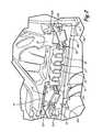
- FIG. 1is a schematic cross-section of a forward portion of a gas turbine engine
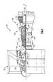
- FIG. 2is a perspective cross-sectional view of a bearing compartment including a first tapered roller bearing, a second tapered roller bearing and a bellows spring;
- FIG. 3is an enlarged cross section of the bellows spring of FIG. 2 ;
- FIG. 4is a schematic cross-section of a gas turbine engine
- FIG. 5is an enlarged schematic cross-section of a sectional of the gas turbine engine which illustrates a front center body case structure
- FIG. 6is a schematic block diagram of a gas turbine engine with the inventive architecture
- FIG. 7is a schematic block diagram of a RELATED ART gas turbine engine with the inventive architecture.
- FIG. 8is an enlarged schematic cross-section of the FIG. 5 sectional of the gas turbine engine which illustrates a load path within the front center body case structure.
- FIG. 1shows a forward section of gas turbine engine 10 above engine centerline C L of gas turbine engine 10 .
- Gas turbine engine 10includes bearing compartment 12 , first and second tapered roller bearings 14 A and 14 B, fan shaft 16 , bearing system 18 , bellows spring 20 , fan hub 22 , nut 23 , fan blades 24 , fan nose 26 , engine shaft 28 , fan drive gear system 30 , compressor section 32 , guide vanes 34 , and engine case 36 .
- Bearing compartment 12is disposed adjacent fan shaft 16 and contains first and second tapered roller bearings 14 A and 14 B therein.
- Fan shaft 16rotates about an axis that aligns with engine centerline axis C L and is supported on tapered roller bearings 14 A and 14 B.
- Bearing compartment 12is bounded by fan shaft 16 and bearing system 18 which connects to the tapered roller bearings 14 A and 14 B.
- Bearing system 18extends to connect to a non-rotational frame such as an engine case of gas turbine engine 10 .
- Bellows spring 20is disposed in bearing compartment 12 adjacent first tapered roller bearing 14 A and second tapered roller bearing 14 B. Bellows spring 20 applies a preload to both first tapered roller bearing 14 A and second tapered roller bearing 14 B.
- Nut 23is positioned adjacent the fan hub 22 and applies a clamping force to the radially inner race portion of first tapered roller bearing 14 A and the inner race portion of second tapered roller bearing 14 B.
- Fan shaft 16connects to and turns fan blades 24 through fan hub 22 .
- Fan hub 22also connects to fan nose 26 .
- Fan shaft 16connects to engine shaft 28 via fan drive gear system 30 .
- Compressor section 32is disposed radially outward of engine centerline C L and is connected to engine shaft 28 .
- Guide vanes 34are disposed radially outward of compressor section 32 and are rotatable relative to engine case 36 .
- gas turbine engine 10comprises a high bypass ratio geared turbofan engine.
- gas turbine engine 10can comprise another type of gas turbine engine used for aircraft propulsion or power generation.
- bearing compartment 12can comprise any bearing compartment in engine 10 .
- Fan shaft 16 and compressor section 32are connected to a turbine section (not shown) through engine shaft 28 .
- Inlet air Aenters engine 10 whereby it is divided into streams of a primary air A P and a secondary air A S after passing through the fan blades 18 .
- the fan blades 24are rotated by turbine section (not shown) of engine 10 through engine shaft 28 to accelerate the secondary air A S (also known as bypass air) through exit guide vanes 34 , thereby producing a significant portion of the thrust output of engine 10 .
- the primary air A P(also known as gas path air) is directed into compressor section 32 .
- Compressor section 32works together to incrementally increase the pressure and temperature of primary air A P .
- FIG. 2shows a perspective cross-sectional view of bearing compartment 12 including first tapered roller bearing 14 A, second tapered roller bearing 14 B, and bellows spring 20 . Additionally, bearing compartment 12 includes seal plate 38 , bearing spacer 40 , gear 42 , secondary sleeve 44 , and squeeze film damper system 46 . First and second tapered roller bearings 14 A and 14 B include inner races 48 A and 48 B, roller elements 50 A and 50 B, and outer races 52 A and 52 B, respectively. Also shown are shoulder 54 of bearing system 18 and shim 56 .
- seal plate 38abuts a forward portion of (as defined by the direction of primary air A P flow within the gas turbine engine 10 ) first tapered roller bearing 14 A.
- Seal plate 38comprises a portion of the carbon sealing system and is disposed adjacent inner race 48 A.
- Bearing spacer 40abuts both inner races 48 A and 48 B to provide necessary spacing between first and second tapered roller bearings 14 A and 14 B.
- Gear 42is contacted by inner race 48 B of second tapered roller bearing 14 B and connects to a shoulder portion of fan shaft 16 .
- secondary sleeve 44is disposed between outer race 52 A of first tapered roller bearing 14 A and bearing system 18 .
- Tapered roller bearings 14 A and 14 Bcan also be supported by squeeze film damper system 46 (of which only seals are shown) disposed between one or more of the tapered roller bearings 14 A and 14 B and bearing system 18 .
- Squeeze film damper systemssuch as the one disclosed herein are well known in the art and are used to shift critical speeds and/or to increase the dynamic stability of a rotor-bearing system.
- first and second tapered roller bearings 14 A and 14 Bhave inner races 48 A and 48 B that are clamped or otherwise affixed to fan shaft 16 .
- Inner races 48 A and 48 Bhave radially outward surfaces (raceways) that interface with roller elements 50 A and 50 B, respectively.
- Outer races 52 A and 52 Binterface with roller elements 50 A and 50 B, respectively, and are mounted to bearing system 18 .
- outer race 52 A of first tapered roller bearing 14 Ais constrained radially and tangentially but can move axially relative to secondary sleeve 44 , bearing system 18 , and portions of squeeze film damper system 46 . This allows roller element 50 A to remain in contact with inner raceway of outer race 52 A.
- Outer race 52 B of second tapered roller bearing 14 Bis fastened to bearing system 18 .
- First and second tapered roller bearings 14 A and 14 Bare retained by bearing system 18 , which reacts loads back through to the engine case 36 .
- a forward end of bellows spring 20is snapped into an interference fit with outer race 52 A, and an aft end of bellows spring 20 is snapped into an interference fit with shoulder 54 of bearing system 18 .
- bellows spring 20is positioned generally between first tapered roller bearing 14 A and second tapered roller bearing 14 B.
- At least one shim 56can be positioned between the aft end of bellows spring 20 and shoulder 54 . Shim 56 allows the spring preload to be accurately set to a desired level without requiring restrictive manufacturing tolerances of bellows spring 20 , bearing system 18 , or other components.
- Nut 23applies a clamping force which reacts through inner race 48 A of first tapered roller bearing 14 A, through bearing spacer 48 , through inner race 48 B of second tapered roller bearing 14 B, and against gear 42 on fan shaft 16 .
- Bellows spring 20applies preload to both first tapered roller bearing 14 A and second tapered roller bearing 14 B.
- bellows spring 20applies preload to outer race 52 A and applies preload to bearing system 18 which transfers preload to outer race 52 B of second tapered roller bearing 14 B.
- FIG. 3shows an enlarged cross section of one embodiment of bellows spring 20 .
- bellows spring 20is a resilient member that is shaped as a corrugated single piece annular ring.
- Bellows spring 20is comprised of a hardened stainless steel.
- Bellows spring 20is lathe turned to produce the corrugated shape shown.
- bellows spring 20can have a cross-sectional thickness that is variable as the bellows spring 20 extends axially along an engine centerline C L ( FIG. 1 ).
- the number of turns (convolutes) of bellows spring 20should be maximized (as limited by the size of the bearing compartment 12 and manufacturing practicality) to allow the bellows spring 20 to better accommodate different tolerances of components within the bearing compartment 12 .
- Analytical toolssuch as commercially available finite element analysis software can be used to simulate stresses on bellows spring 20 in order to optimize its geometry (number of turns, cross-sectional thicknesses, etc.) and performance.
- the turns of bellow spring 20have a modified omega shape, that is each convolute section 58 of bellows spring 20 extends forward and aft of adjacent interconnection sections 60 (i.e., bellows spring 20 has sections 58 which bend forward or aft relative adjacent sections 60 ).
- Other embodimentscan have parallel convolutes to simplify the manufacturing of bellows spring 20 .
- bellows spring 20to apply preload to first tapered roller bearing 14 A and second tapered roller bearing 14 B allows a single element to be used in the confined space of bearing compartment 12 , thereby saving space and reducing manufacturing costs.
- Bellows spring 20is adapted to apply preload to first and second tapered roller bearings 14 A and 14 B in the axial direction along the engine centerline C L ( FIG. 1 ), and act as a centering spring (i.e., have a radial stiffness with respect to the engine centerline C L ) for the squeeze film damper system 46 ( FIG. 2 ).
- Bellows spring 20is accommodating of flexing in the radial direction by first tapered roller bearing 14 A and the second tapered roller bearing 14 B such that bellows spring 20 does not excessively wear on the surfaces of the bearings 14 A and 14 B.
- FIG. 4schematically illustrates another exemplary gas turbine engine 120 .
- the gas turbine engine 120is disclosed herein as a two-spool turbofan that generally incorporates a fan section 122 , a compressor section 124 , a combustor section 126 and a turbine section 128 .
- Alternative enginesmight include an augmentor section (not shown) among other systems or features.
- the fan section 122drives air along a bypass flowpath while the compressor section 124 drives air along a core flowpath for compression and communication into the combustor section 126 then expansion through the turbine section 128 .
- turbofan gas turbine enginein the disclosed non-limiting embodiment, it should be understood that the concepts described herein are not limited to use with turbofans as the teachings may be applied to other types of turbine engines such as a three-spool (plus fan) engine wherein an intermediate spool includes an intermediate pressure compressor (IPC) between the LPC and HPC and an intermediate pressure turbine (IPT) between the HPT and LPT.
- IPCintermediate pressure compressor
- IPTintermediate pressure turbine
- the engine 120generally includes a low spool 130 and a high spool 132 mounted for rotation about an engine central longitudinal axis A relative to an engine static structure 136 via several bearing supports 138 .
- the low spool 130generally includes an inner shaft 140 that interconnects a fan 142 , a low pressure compressor 144 and a low pressure turbine 146 .
- the inner shaft 140drives the fan 142 through a geared architecture 148 to drive the fan 142 at a lower speed than the low spool 130 .
- An exemplary reduction transmissionis an epicyclic transmission, namely a planetary or star gear system.
- the high spool 132includes an outer shaft 150 that interconnects a high pressure compressor 152 and high pressure turbine 154 .
- a combustor 156is arranged between the high pressure compressor 152 and the high pressure turbine 154 .
- the inner shaft 140 and the outer shaft 150are concentric and rotate about the engine central longitudinal axis A which is collinear with their longitudinal axes.
- Core airflowis compressed by the low pressure compressor 144 then the high pressure compressor 152 , mixed with the fuel and burned in the combustor 156 , then expanded over the high pressure turbine 154 and low pressure turbine 146 .
- the turbines 154 , 146rotationally drive the respective low spool 130 and high spool 132 in response to the expansion.
- bearing supports 138includes a #2 bearing system 138 - 2 located radially inboard of the compressor section 124 .
- the engine static structure 136 proximate the compressor section 124generally includes a front center body case structure 160 and an intermediate case structure 162 which mounts aft of the front center body case structure 160 . It should be appreciate that various case structures may alternatively or additionally be provided, yet benefit from the architecture described herein.
- the front center body case structure 160generally defines an annular core flow path 164 A for the core airflow into the low pressure compressor 144 .
- the intermediate case structure 162defines a core flow path 164 B which continues the core flow path 164 A for the core airflow into the high pressure compressor 152 of core flow path 164 C.
- the core flow path 164 Bis generally radially inward of the core flow path 164 A to transition into the radially smaller diameter core flow path 164 C. That is, the core flow path 164 B defines a “wasp waist” gas turbine engine architecture.
- a #2 bearing system 138 - 2at least partially supports the inner shaft 140 relative to the front center body case structure 160 .
- a #3 bearing system 138 - 3generally supports the outer shaft 150 relative the intermediate case structure 162 . That is, the #2 bearing system 138 - 2 at least partially supports the low spool 130 and the #3 bearing system 138 - 3 generally supports the high spool 132 . It should be appreciated that various bearing systems such as thrust bearing structures and mount arrangements will benefit herefrom.
- a flex support 168provides a flexible attachment of the geared architecture 48 within the front center body case structure 160 .
- the flex support 168reacts the torsional loads from the geared architecture 148 and facilitates vibration absorption as well as other support functions.
- a centering spring 170which is a generally cylindrical cage-like structural component with a multiple of beams that extend between flange end structures resiliently positions the #2 bearing system 138 - 2 with respect to the low spool 130 .
- the beamsare double-tapered beams arrayed circumferentially to control a radial spring rate that may be selected based on a plurality of considerations including, but not limited to, bearing loading, bearing life, rotor dynamics, and rotor deflection considerations.
- the gearbox 172 of the geared architecture 148is driven by the low spool 130 in the disclosed non-limiting embodiment through a coupling shaft 174 .
- the coupling shaft 174transfers torque bearing system to the gearbox 172 .
- the #2 bearing system 138 - 2 sfacilitates the segregation of vibrations and other transients from the gearbox 172 .
- the coupling shaft 174 in the disclosed non-limiting embodimentincludes a forward coupling shaft section 176 and an aft coupling shaft section 178 .
- the forward coupling shaft section 176includes an interface spline 180 which mates with the gearbox 172 .
- An interface spline 182 of the aft coupling shaft section 178connects the coupling shaft 174 to the low spool 130 through, in this non limiting embodiment, a low pressure compressor hub 184 of the low pressure compressor 144 .
- a fan rotor bearing system structure 186 aft of the fan 142extends radially inward from the front center body case structure 160 .
- the fan rotor bearing system structure 86 and the front center body case structure 160define a bearing compartment B.
- various bearing supports 138 - 1 and seals 188may be supported by the fan rotor bearing system structure 186 to contain oil and support rotation of an output shaft 200 which connects with the geared architecture 148 to drive the fan 142 .
- the low pressure compressor hub 184 of the low pressure compressor 144includes a tubular hub 190 and a frustro-conical web 192 .
- the tubular hub 190mounts to the inner shaft 140 through, for example, a splined interface.
- the tubular hub 190is adjacent to the #2 bearing system 138 - 2 .
- the frustro-conical web 192extends in a forwardly direction from the tubular hub 190 axially between the #2 bearing system 138 - 2 and the #3 bearing system 138 - 3 (also shown in FIG. 6 ). That is, the frustro-conical web 192 is axially located between the bearing supports 138 - 2 , 138 - 3 .
- the frustro-conical web 192mounts to a low pressure compressor rotor 194 of the low pressure compressor 144 .
- the frustro-conical web 192extends between the bearing supports 138 - 2 , 138 - 3 and mounts to a second stage of a three stage low pressure compressor rotor 194 .
- the frustro-conical web 192may mount to other stages in other engine architectures and such architectures may include other numbers of stages.
- Locating the low pressure compressor hub 184 between the #2 bearing system 138 - 2 and the #3 bearing system 138 - 3offers significant advantage to reduce deflection for the geared architecture 48 as compared to a related art architecture such as the example illustrated in FIG. 7 ; RELATED ART. That is, both end sections of the coupling shaft 174 are tied to the front center body case structure 160 such that relative deflections between the end sections thereof are greatly reduced. This facilitates a more efficient balance of baseline torque, FBO torques, maneuver deflections and the minimization of the overall loads that are translated into the geared architecture 148 .
- a relatively less complicated bearing compartment B which facilitates increased manufacturing tolerancesis defined to, for example, require fewer seals which minimizes potential oil leak sources and saves weight.
- the architecturefurther facilitates an efficient load path (L; FIG. 8 ) for the geared architecture and an overall lower overall heat generation and oil flow. That is, a more compact load path L is defined by the forward center body structure 160 alone. Secondary benefits are reduced oil tank size, reduced cooler sizing and reduce oil quantity in the engine lubrication system.
Landscapes
- Engineering & Computer Science (AREA)
- General Engineering & Computer Science (AREA)
- Mechanical Engineering (AREA)
- Chemical & Material Sciences (AREA)
- Combustion & Propulsion (AREA)
- Structures Of Non-Positive Displacement Pumps (AREA)
- Rolling Contact Bearings (AREA)
Abstract
Description
Claims (23)
Priority Applications (9)
| Application Number | Priority Date | Filing Date | Title |
|---|---|---|---|
| US13/304,053US9784181B2 (en) | 2009-11-20 | 2011-11-23 | Gas turbine engine architecture with low pressure compressor hub between high and low rotor thrust bearings |
| BR102012027097-8ABR102012027097B1 (en) | 2011-11-23 | 2012-10-22 | GAS TURBINE ENGINE |
| CA2794888ACA2794888C (en) | 2011-11-23 | 2012-11-07 | Gas turbine engine architecture with low pressure compressor hub between high and low rotor thrust bearings |
| EP20195153.0AEP3779167A3 (en) | 2011-11-23 | 2012-11-15 | Gas turbine engine architecture with low pressure compressor hub between high and low rotor thrust bearings |
| EP12192792.5AEP2597292B2 (en) | 2011-11-23 | 2012-11-15 | Gas turbine engine architecture with low pressure compressor hub between high and low rotor thrust bearings |
| RU2012148833/06ARU2012148833A (en) | 2011-11-23 | 2012-11-19 | GAS TURBINE ENGINE (OPTIONS) |
| RU2015151747ARU2688073C2 (en) | 2011-11-23 | 2012-11-19 | Gas turbine engine (variants) |
| JP2012255781AJP5596109B2 (en) | 2011-11-23 | 2012-11-22 | Gas turbine engine |
| CN201210481399.0ACN103133141B (en) | 2011-11-23 | 2012-11-23 | Gas turbine engine |
Applications Claiming Priority (2)
| Application Number | Priority Date | Filing Date | Title |
|---|---|---|---|
| US12/622,535US8439637B2 (en) | 2009-11-20 | 2009-11-20 | Bellows preload and centering spring for a fan drive gear system |
| US13/304,053US9784181B2 (en) | 2009-11-20 | 2011-11-23 | Gas turbine engine architecture with low pressure compressor hub between high and low rotor thrust bearings |
Related Parent Applications (1)
| Application Number | Title | Priority Date | Filing Date |
|---|---|---|---|
| US12/622,535Continuation-In-PartUS8439637B2 (en) | 2009-11-20 | 2009-11-20 | Bellows preload and centering spring for a fan drive gear system |
Publications (2)
| Publication Number | Publication Date |
|---|---|
| US20120195753A1 US20120195753A1 (en) | 2012-08-02 |
| US9784181B2true US9784181B2 (en) | 2017-10-10 |
Family
ID=46577505
Family Applications (1)
| Application Number | Title | Priority Date | Filing Date |
|---|---|---|---|
| US13/304,053Active2031-08-05US9784181B2 (en) | 2009-11-20 | 2011-11-23 | Gas turbine engine architecture with low pressure compressor hub between high and low rotor thrust bearings |
Country Status (1)
| Country | Link |
|---|---|
| US (1) | US9784181B2 (en) |
Cited By (2)
| Publication number | Priority date | Publication date | Assignee | Title |
|---|---|---|---|---|
| US20190128182A1 (en)* | 2013-03-15 | 2019-05-02 | United Technologies Corporation | Turbofan Engine Bearing and Gearbox Arrangement |
| FR3122703A1 (en)* | 2021-05-07 | 2022-11-11 | Safran Transmission Systems | Flexible transmission part for turbomachine reducer |
Families Citing this family (31)
| Publication number | Priority date | Publication date | Assignee | Title |
|---|---|---|---|---|
| US9976443B2 (en) | 2009-11-20 | 2018-05-22 | United Technologies Corporation | Turbofan engine assembly methods |
| US8777793B2 (en) | 2011-04-27 | 2014-07-15 | United Technologies Corporation | Fan drive planetary gear system integrated carrier and torque frame |
| US8979484B2 (en) | 2012-01-05 | 2015-03-17 | Pratt & Whitney Canada Corp. | Casing for an aircraft turbofan bypass engine |
| US10400629B2 (en)* | 2012-01-31 | 2019-09-03 | United Technologies Corporation | Gas turbine engine shaft bearing configuration |
| US8863491B2 (en) | 2012-01-31 | 2014-10-21 | United Technologies Corporation | Gas turbine engine shaft bearing configuration |
| US9038366B2 (en) | 2012-01-31 | 2015-05-26 | United Technologies Corporation | LPC flowpath shape with gas turbine engine shaft bearing configuration |
| US9869249B2 (en) | 2012-01-31 | 2018-01-16 | United Technologies Corporation | Speed sensor probe location in gas turbine engine |
| US8402741B1 (en) | 2012-01-31 | 2013-03-26 | United Technologies Corporation | Gas turbine engine shaft bearing configuration |
| US9410427B2 (en) | 2012-06-05 | 2016-08-09 | United Technologies Corporation | Compressor power and torque transmitting hub |
| US9163522B2 (en) | 2012-08-21 | 2015-10-20 | United Technologies Corporation | Spring carrier and removable seal carrier |
| US9915199B2 (en)* | 2012-10-08 | 2018-03-13 | United Technologies Corporation | Bi-directional compression fan rotor for a gas turbine engine |
| EP2906807B1 (en)* | 2012-10-09 | 2021-09-08 | Raytheon Technologies Corporation | Geared turbofan engine with inter-shaft deflection feature |
| US20140290211A1 (en)* | 2013-03-13 | 2014-10-02 | United Technologies Corporation | Turbine engine including balanced low pressure stage count |
| EP3546726B1 (en)* | 2013-03-14 | 2021-12-15 | Raytheon Technologies Corporation | Turbofan engine assembly methods |
| WO2014151470A1 (en)* | 2013-03-15 | 2014-09-25 | United Technologies Corporation | Fan axial containment system |
| EP2971675B1 (en)* | 2013-03-15 | 2021-11-03 | Raytheon Technologies Corporation | Speed sensor probe location in a gas turbine engine |
| EP3027866A4 (en)* | 2013-07-31 | 2017-04-26 | United Technologies Corporation | Lpc flowpath shape with gas turbine engine shaft bearing configuration |
| EP3027877A4 (en)* | 2013-07-31 | 2017-04-05 | United Technologies Corporation | Gas turbine engine shaft bearing configuration |
| US20160222815A1 (en)* | 2013-10-01 | 2016-08-04 | United Technologies Corporation | High Efficiency Geared Turbofan |
| FR3013385B1 (en)* | 2013-11-21 | 2015-11-13 | Snecma | PRE-SEALED SPEAKER DURING MODULAR DISASSEMBLY OF A REDUCING TURBOREACTOR |
| US20150176530A1 (en)* | 2013-12-19 | 2015-06-25 | United Technologies Corporation | Ultra high overall pessure ratio gas turbine engine |
| CN104019091B (en)* | 2014-06-11 | 2016-02-24 | 西北工业大学 | The design method of low-pressure turbine rear axle |
| GB201421882D0 (en)* | 2014-12-09 | 2015-01-21 | Rolls Royce Plc | Bearing load sharing system |
| US10066734B2 (en)* | 2015-12-07 | 2018-09-04 | United Technologies Corporation | Gear driven gas turbine engine assembly |
| FR3046202B1 (en) | 2015-12-24 | 2017-12-29 | Snecma | TURBOREACTOR WITH MEANS OF PUSH RESUME ON THE INTER-COMPRESSOR HOUSING |
| FR3049008B1 (en)* | 2016-03-15 | 2018-03-02 | Safran Aircraft Engines | TURBOREACTOR COMPRISING A LOWER SUPERCRITICAL PRESSURE TREE |
| FR3075881B1 (en)* | 2017-12-22 | 2020-06-26 | Safran Aircraft Engines | BLOWER MODULE COMPRISING MEANS FOR SEALING A LUBRICANT ENCLOSURE |
| GB2583129A (en)* | 2019-04-18 | 2020-10-21 | Rolls Royce Plc | A shaft catcher system |
| US11629649B2 (en) | 2020-05-11 | 2023-04-18 | Raytheon Technologies Corporation | Gas turbine engine with speed sensor |
| CN115949670B (en)* | 2023-03-09 | 2023-06-30 | 中国航发四川燃气涡轮研究院 | Elastic structure for axial compression of bearing |
| FR3146658B1 (en)* | 2023-03-16 | 2025-02-14 | Safran Aircraft Engines | Assembly comprising a shaft section guided by a flexibly held bearing |
Citations (23)
| Publication number | Priority date | Publication date | Assignee | Title |
|---|---|---|---|---|
| US3434288A (en)* | 1966-03-09 | 1969-03-25 | Rolls Royce | By-pass gas turbine engine |
| US4084861A (en) | 1976-11-11 | 1978-04-18 | United Technologies Corporation | Thrust bearing damping means |
| US4704862A (en) | 1985-05-29 | 1987-11-10 | United Technologies Corporation | Ducted prop engine |
| GB2199375A (en) | 1986-12-23 | 1988-07-06 | Rolls Royce Plc | A turbofan gas turbine engine |
| US4867655A (en) | 1988-03-14 | 1989-09-19 | United Technologies Corporation | Variable stiffness oil film damper |
| US4916894A (en)* | 1989-01-03 | 1990-04-17 | General Electric Company | High bypass turbofan engine having a partially geared fan drive turbine |
| US4952076A (en) | 1989-07-21 | 1990-08-28 | United Technologies Corporation | Fluid damper for thrust bearing |
| US4951461A (en) | 1989-03-20 | 1990-08-28 | General Electric Company | Power turbine support arrangement |
| US4981415A (en) | 1989-08-16 | 1991-01-01 | United Technologies Corporation | Support for oil film dampers |
| US5010729A (en) | 1989-01-03 | 1991-04-30 | General Electric Company | Geared counterrotating turbine/fan propulsion system |
| US5433674A (en)* | 1994-04-12 | 1995-07-18 | United Technologies Corporation | Coupling system for a planetary gear train |
| US5622438A (en) | 1995-07-12 | 1997-04-22 | United Technologies Corporation | Fire resistant bearing compartment cover |
| US5791789A (en) | 1997-04-24 | 1998-08-11 | United Technologies Corporation | Rotor support for a turbine engine |
| US6439772B1 (en) | 2000-12-01 | 2002-08-27 | General Electric Company | Method and apparatus for supporting rotor assembly bearings |
| CN1654805A (en) | 2004-02-11 | 2005-08-17 | Snecma发动机公司 | Turbojet structure with two fans at the front end |
| US20080006018A1 (en)* | 2006-07-05 | 2008-01-10 | United Technologies Corporation | Oil baffle for gas turbine fan drive gear system |
| US20080098715A1 (en)* | 2006-10-31 | 2008-05-01 | Robert Joseph Orlando | Turbofan engine assembly and method of assembling same |
| US20080098717A1 (en)* | 2006-10-31 | 2008-05-01 | Robert Joseph Orlando | Turbofan engine assembly and method of assembling same |
| US20090123271A1 (en) | 2007-11-13 | 2009-05-14 | Coffin James B | Fan shaft retention |
| US20100247306A1 (en) | 2009-03-26 | 2010-09-30 | Merry Brian D | Gas turbine engine with 2.5 bleed duct core case section |
| US20110047959A1 (en)* | 2009-09-02 | 2011-03-03 | United Technologies Corporation | Air particle separator for a gas turbine engine |
| US20110123326A1 (en) | 2009-11-20 | 2011-05-26 | United Technologies Corporation | Bellows preload and centering spring for a fan drive gear system |
| US20110219781A1 (en) | 2010-03-10 | 2011-09-15 | Daniel Benjamin | Gas turbine engine with tie shaft for axial high pressure compressor rotor |
- 2011
- 2011-11-23USUS13/304,053patent/US9784181B2/enactiveActive
Patent Citations (30)
| Publication number | Priority date | Publication date | Assignee | Title |
|---|---|---|---|---|
| US3434288A (en)* | 1966-03-09 | 1969-03-25 | Rolls Royce | By-pass gas turbine engine |
| US4084861A (en) | 1976-11-11 | 1978-04-18 | United Technologies Corporation | Thrust bearing damping means |
| US4704862A (en) | 1985-05-29 | 1987-11-10 | United Technologies Corporation | Ducted prop engine |
| GB2199375A (en) | 1986-12-23 | 1988-07-06 | Rolls Royce Plc | A turbofan gas turbine engine |
| US4827712A (en)* | 1986-12-23 | 1989-05-09 | Rolls-Royce Plc | Turbofan gas turbine engine |
| US4867655A (en) | 1988-03-14 | 1989-09-19 | United Technologies Corporation | Variable stiffness oil film damper |
| US4916894A (en)* | 1989-01-03 | 1990-04-17 | General Electric Company | High bypass turbofan engine having a partially geared fan drive turbine |
| US5010729A (en) | 1989-01-03 | 1991-04-30 | General Electric Company | Geared counterrotating turbine/fan propulsion system |
| US4951461A (en) | 1989-03-20 | 1990-08-28 | General Electric Company | Power turbine support arrangement |
| US4952076A (en) | 1989-07-21 | 1990-08-28 | United Technologies Corporation | Fluid damper for thrust bearing |
| US4981415A (en) | 1989-08-16 | 1991-01-01 | United Technologies Corporation | Support for oil film dampers |
| US5433674A (en)* | 1994-04-12 | 1995-07-18 | United Technologies Corporation | Coupling system for a planetary gear train |
| WO1995027860A1 (en) | 1994-04-12 | 1995-10-19 | United Technologies Corporation | Coupling system for a planetary gear train |
| US5622438A (en) | 1995-07-12 | 1997-04-22 | United Technologies Corporation | Fire resistant bearing compartment cover |
| US5791789A (en) | 1997-04-24 | 1998-08-11 | United Technologies Corporation | Rotor support for a turbine engine |
| US6439772B1 (en) | 2000-12-01 | 2002-08-27 | General Electric Company | Method and apparatus for supporting rotor assembly bearings |
| CN1654805A (en) | 2004-02-11 | 2005-08-17 | Snecma发动机公司 | Turbojet structure with two fans at the front end |
| EP1564397A1 (en) | 2004-02-11 | 2005-08-17 | Snecma Moteurs | Jet engine architecture having two fans at the front end |
| US7412819B2 (en)* | 2004-02-11 | 2008-08-19 | Snecma | Turbojet architecture with two fans at the front |
| US20080006018A1 (en)* | 2006-07-05 | 2008-01-10 | United Technologies Corporation | Oil baffle for gas turbine fan drive gear system |
| EP1921253A2 (en) | 2006-10-31 | 2008-05-14 | General Electric Company | Turbofan engine assembly and method of assembling same |
| US20080098717A1 (en)* | 2006-10-31 | 2008-05-01 | Robert Joseph Orlando | Turbofan engine assembly and method of assembling same |
| US20080098715A1 (en)* | 2006-10-31 | 2008-05-01 | Robert Joseph Orlando | Turbofan engine assembly and method of assembling same |
| US20090123271A1 (en) | 2007-11-13 | 2009-05-14 | Coffin James B | Fan shaft retention |
| EP2060809A1 (en) | 2007-11-13 | 2009-05-20 | United Technologies Corporation | Fan shaft retention |
| US20100247306A1 (en) | 2009-03-26 | 2010-09-30 | Merry Brian D | Gas turbine engine with 2.5 bleed duct core case section |
| US20110047959A1 (en)* | 2009-09-02 | 2011-03-03 | United Technologies Corporation | Air particle separator for a gas turbine engine |
| EP2299092A2 (en) | 2009-09-02 | 2011-03-23 | United Technologies Corporation | Air Particle Separator for a Gas Turbine Engine |
| US20110123326A1 (en) | 2009-11-20 | 2011-05-26 | United Technologies Corporation | Bellows preload and centering spring for a fan drive gear system |
| US20110219781A1 (en) | 2010-03-10 | 2011-09-15 | Daniel Benjamin | Gas turbine engine with tie shaft for axial high pressure compressor rotor |
Non-Patent Citations (5)
| Title |
|---|
| Chinese Search Report for Chinese Patent Application No. 201210481399.0 mailed on Sep. 29, 2014. |
| European Search Report for Application No. 12192792.5 received Nov. 15, 2016. |
| Fledderjohn, "The TFE731-5: Evolution of a Decade of Businesse Jet Service", SAE Technical Paper, Business Aircraft Meeting & Exposition Apr. 12-15, 1983.* |
| Partial European Search Report for Application No. 12192792.5 dated Aug. 9, 2016. |
| Shlyachtenko, S.M., Theory and Design of Air-Jet Engines, Moscow, "Mashinostroyeniye", Publishing House, 1987, pp. 15-19. |
Cited By (3)
| Publication number | Priority date | Publication date | Assignee | Title |
|---|---|---|---|---|
| US20190128182A1 (en)* | 2013-03-15 | 2019-05-02 | United Technologies Corporation | Turbofan Engine Bearing and Gearbox Arrangement |
| US10830131B2 (en)* | 2013-03-15 | 2020-11-10 | Raytheon Technologies Corporation | Turbofan engine bearing and gearbox arrangement |
| FR3122703A1 (en)* | 2021-05-07 | 2022-11-11 | Safran Transmission Systems | Flexible transmission part for turbomachine reducer |
Also Published As
| Publication number | Publication date |
|---|---|
| US20120195753A1 (en) | 2012-08-02 |
Similar Documents
| Publication | Publication Date | Title |
|---|---|---|
| US9784181B2 (en) | Gas turbine engine architecture with low pressure compressor hub between high and low rotor thrust bearings | |
| CA2794888C (en) | Gas turbine engine architecture with low pressure compressor hub between high and low rotor thrust bearings | |
| US10920603B2 (en) | Gas turbine engine forward bearing compartment architecture | |
| US10830131B2 (en) | Turbofan engine bearing and gearbox arrangement | |
| US11486269B2 (en) | Gas turbine engine shaft bearing configuration | |
| US9410483B2 (en) | Gas turbine engine forward bearing compartment architecture | |
| US8439637B2 (en) | Bellows preload and centering spring for a fan drive gear system | |
| EP3027877A1 (en) | Gas turbine engine shaft bearing configuration | |
| EP3109411A1 (en) | Gas turbine engine forward bearing compartment architecture |
Legal Events
| Date | Code | Title | Description |
|---|---|---|---|
| AS | Assignment | Owner name:UNITED TECHNOLOGIES CORPORATION, CONNECTICUT Free format text:ASSIGNMENT OF ASSIGNORS INTEREST;ASSIGNORS:DAVIS, TODD A.;REINHARDT, GREGORY E.;DIBENEDETTO, ENZO;SIGNING DATES FROM 20111122 TO 20111220;REEL/FRAME:027499/0328 | |
| STCF | Information on status: patent grant | Free format text:PATENTED CASE | |
| AS | Assignment | Owner name:RAYTHEON TECHNOLOGIES CORPORATION, MASSACHUSETTS Free format text:CHANGE OF NAME;ASSIGNOR:UNITED TECHNOLOGIES CORPORATION;REEL/FRAME:054062/0001 Effective date:20200403 | |
| AS | Assignment | Owner name:RAYTHEON TECHNOLOGIES CORPORATION, CONNECTICUT Free format text:CORRECTIVE ASSIGNMENT TO CORRECT THE AND REMOVE PATENT APPLICATION NUMBER 11886281 AND ADD PATENT APPLICATION NUMBER 14846874. TO CORRECT THE RECEIVING PARTY ADDRESS PREVIOUSLY RECORDED AT REEL: 054062 FRAME: 0001. ASSIGNOR(S) HEREBY CONFIRMS THE CHANGE OF ADDRESS;ASSIGNOR:UNITED TECHNOLOGIES CORPORATION;REEL/FRAME:055659/0001 Effective date:20200403 | |
| MAFP | Maintenance fee payment | Free format text:PAYMENT OF MAINTENANCE FEE, 4TH YEAR, LARGE ENTITY (ORIGINAL EVENT CODE: M1551); ENTITY STATUS OF PATENT OWNER: LARGE ENTITY Year of fee payment:4 | |
| AS | Assignment | Owner name:RTX CORPORATION, CONNECTICUT Free format text:CHANGE OF NAME;ASSIGNOR:RAYTHEON TECHNOLOGIES CORPORATION;REEL/FRAME:064714/0001 Effective date:20230714 | |
| MAFP | Maintenance fee payment | Free format text:PAYMENT OF MAINTENANCE FEE, 8TH YEAR, LARGE ENTITY (ORIGINAL EVENT CODE: M1552); ENTITY STATUS OF PATENT OWNER: LARGE ENTITY Year of fee payment:8 |