US9782562B2 - Venous insufficiency treatment method - Google Patents
Venous insufficiency treatment methodDownload PDFInfo
- Publication number
- US9782562B2 US9782562B2US14/989,167US201614989167AUS9782562B2US 9782562 B2US9782562 B2US 9782562B2US 201614989167 AUS201614989167 AUS 201614989167AUS 9782562 B2US9782562 B2US 9782562B2
- Authority
- US
- United States
- Prior art keywords
- catheter
- fluid
- sclerosant
- exits
- vein
- Prior art date
- Legal status (The legal status is an assumption and is not a legal conclusion. Google has not performed a legal analysis and makes no representation as to the accuracy of the status listed.)
- Expired - Fee Related
Links
- 238000000034methodMethods0.000titleclaimsabstractdescription77
- 238000011282treatmentMethods0.000titleclaimsabstractdescription34
- 201000002282venous insufficiencyDiseases0.000titledescription6
- 239000003229sclerosing agentSubstances0.000claimsabstractdescription83
- 239000012530fluidSubstances0.000claimsabstractdescription49
- 238000001802infusionMethods0.000claimsabstractdescription30
- 206010046996Varicose veinDiseases0.000claimsabstractdescription13
- 238000010790dilutionMethods0.000claimsabstractdescription9
- 239000012895dilutionSubstances0.000claimsabstractdescription9
- 208000027185varicose diseaseDiseases0.000claimsabstractdescription7
- 208000019553vascular diseaseDiseases0.000claimsabstractdescription5
- 206010002091AnaesthesiaDiseases0.000claimsdescription11
- 230000037005anaesthesiaEffects0.000claimsdescription11
- 208000005392SpasmDiseases0.000claimsdescription6
- 210000004204blood vesselAnatomy0.000claims4
- 230000001939inductive effectEffects0.000claims1
- 210000003462veinAnatomy0.000description101
- 229940079593drugDrugs0.000description37
- 239000003814drugSubstances0.000description37
- 238000002347injectionMethods0.000description27
- 239000007924injectionSubstances0.000description27
- 239000008280bloodSubstances0.000description22
- 210000004369bloodAnatomy0.000description22
- 239000006260foamSubstances0.000description22
- 239000013307optical fiberSubstances0.000description12
- 238000002604ultrasonographyMethods0.000description12
- 239000007788liquidSubstances0.000description11
- 230000006835compressionEffects0.000description10
- 238000007906compressionMethods0.000description10
- 210000003752saphenous veinAnatomy0.000description10
- 230000017531blood circulationEffects0.000description9
- 238000007669thermal treatmentMethods0.000description9
- 238000007632sclerotherapyMethods0.000description6
- 238000013461designMethods0.000description5
- 238000003780insertionMethods0.000description5
- 230000037431insertionEffects0.000description5
- 230000006378damageEffects0.000description4
- 239000000463materialSubstances0.000description4
- 238000013508migrationMethods0.000description4
- 230000005012migrationEffects0.000description4
- 230000009467reductionEffects0.000description4
- 208000034656ContusionsDiseases0.000description3
- 206010051055Deep vein thrombosisDiseases0.000description3
- 206010047249Venous thrombosisDiseases0.000description3
- 230000003444anaesthetic effectEffects0.000description3
- 230000008901benefitEffects0.000description3
- 238000002594fluoroscopyMethods0.000description3
- 238000013507mappingMethods0.000description3
- 238000002360preparation methodMethods0.000description3
- 230000008569processEffects0.000description3
- 239000000126substanceSubstances0.000description3
- 238000002560therapeutic procedureMethods0.000description3
- UCTWMZQNUQWSLP-VIFPVBQESA-N(R)-adrenalineChemical compoundCNC[C@H](O)C1=CC=C(O)C(O)=C1UCTWMZQNUQWSLP-VIFPVBQESA-N0.000description2
- 229930182837(R)-adrenalineNatural products0.000description2
- NNJVILVZKWQKPM-UHFFFAOYSA-NLidocaineChemical compoundCCN(CC)CC(=O)NC1=C(C)C=CC=C1CNNJVILVZKWQKPM-UHFFFAOYSA-N0.000description2
- FAPWRFPIFSIZLT-UHFFFAOYSA-MSodium chlorideChemical compound[Na+].[Cl-]FAPWRFPIFSIZLT-UHFFFAOYSA-M0.000description2
- 206010068149Vessel perforationDiseases0.000description2
- 206010052428WoundDiseases0.000description2
- 239000003795chemical substances by applicationSubstances0.000description2
- 229960005139epinephrineDrugs0.000description2
- 239000000835fiberSubstances0.000description2
- 230000006870functionEffects0.000description2
- 238000002695general anesthesiaMethods0.000description2
- 239000003193general anesthetic agentSubstances0.000description2
- 238000002647laser therapyMethods0.000description2
- 229960004194lidocaineDrugs0.000description2
- 238000002690local anesthesiaMethods0.000description2
- 230000017074necrotic cell deathEffects0.000description2
- 230000000926neurological effectEffects0.000description2
- 230000036407painEffects0.000description2
- 238000011084recoveryMethods0.000description2
- 238000007789sealingMethods0.000description2
- 231100000075skin burnToxicity0.000description2
- 239000011780sodium chlorideSubstances0.000description2
- 229960000776sodium tetradecyl sulfateDrugs0.000description2
- UPUIQOIQVMNQAP-UHFFFAOYSA-Msodium;tetradecyl sulfateChemical compound[Na+].CCCCCCCCCCCCCCOS([O-])(=O)=OUPUIQOIQVMNQAP-UHFFFAOYSA-M0.000description2
- 208000024891symptomDiseases0.000description2
- 230000000007visual effectEffects0.000description2
- ZCYVEMRRCGMTRW-UHFFFAOYSA-N7553-56-2Chemical compound[I]ZCYVEMRRCGMTRW-UHFFFAOYSA-N0.000description1
- 208000032170Congenital AbnormalitiesDiseases0.000description1
- 238000012276Endovascular treatmentMethods0.000description1
- WQZGKKKJIJFFOK-GASJEMHNSA-NGlucoseNatural productsOC[C@H]1OC(O)[C@H](O)[C@@H](O)[C@@H]1OWQZGKKKJIJFFOK-GASJEMHNSA-N0.000description1
- 208000032843HemorrhageDiseases0.000description1
- 208000008883Patent Foramen OvaleDiseases0.000description1
- 229920001363PolidocanolPolymers0.000description1
- 206010048591Post thrombotic syndromeDiseases0.000description1
- 208000003251PruritusDiseases0.000description1
- 206010040943Skin UlcerDiseases0.000description1
- 208000025865UlcerDiseases0.000description1
- 208000027418Wounds and injuryDiseases0.000description1
- 238000002679ablationMethods0.000description1
- 229940035674anestheticsDrugs0.000description1
- 238000013459approachMethods0.000description1
- 230000004888barrier functionEffects0.000description1
- 230000009286beneficial effectEffects0.000description1
- 230000005540biological transmissionEffects0.000description1
- 208000034158bleedingDiseases0.000description1
- 230000000740bleeding effectEffects0.000description1
- 238000009954braidingMethods0.000description1
- SIEYLFHKZGLBNX-UHFFFAOYSA-Nbupivacaine hydrochloride (anhydrous)Chemical compound[Cl-].CCCC[NH+]1CCCCC1C(=O)NC1=C(C)C=CC=C1CSIEYLFHKZGLBNX-UHFFFAOYSA-N0.000description1
- 238000006243chemical reactionMethods0.000description1
- -1chromated gylcerinChemical compound0.000description1
- 230000001149cognitive effectEffects0.000description1
- 239000002872contrast mediaSubstances0.000description1
- 238000007796conventional methodMethods0.000description1
- 239000002537cosmeticSubstances0.000description1
- 230000007423decreaseEffects0.000description1
- 230000003247decreasing effectEffects0.000description1
- 230000001419dependent effectEffects0.000description1
- 208000037265diseases, disorders, signs and symptomsDiseases0.000description1
- 238000006073displacement reactionMethods0.000description1
- 238000012377drug deliveryMethods0.000description1
- 230000000694effectsEffects0.000description1
- 230000008030eliminationEffects0.000description1
- 238000003379elimination reactionMethods0.000description1
- 210000003414extremityAnatomy0.000description1
- 239000000945fillerSubstances0.000description1
- 239000008103glucoseSubstances0.000description1
- 208000025339heart septal defectDiseases0.000description1
- 238000003384imaging methodMethods0.000description1
- 229910052740iodineInorganic materials0.000description1
- 239000011630iodineSubstances0.000description1
- 239000002085irritantSubstances0.000description1
- 231100000021irritantToxicity0.000description1
- 238000002955isolationMethods0.000description1
- 230000007803itchingEffects0.000description1
- 238000003698laser cuttingMethods0.000description1
- 238000013532laser treatmentMethods0.000description1
- 208000005592lipodermatosclerosisDiseases0.000description1
- 230000007774longtermEffects0.000description1
- 210000003141lower extremityAnatomy0.000description1
- 210000004072lungAnatomy0.000description1
- 238000004519manufacturing processMethods0.000description1
- 229940106885marcaineDrugs0.000description1
- 239000003550markerSubstances0.000description1
- 239000007769metal materialSubstances0.000description1
- 239000004005microsphereSubstances0.000description1
- 239000000203mixtureSubstances0.000description1
- 238000012986modificationMethods0.000description1
- 230000004048modificationEffects0.000description1
- 238000012544monitoring processMethods0.000description1
- 210000005036nerveAnatomy0.000description1
- 208000035824paresthesiaDiseases0.000description1
- 230000000149penetrating effectEffects0.000description1
- 208000001297phlebitisDiseases0.000description1
- ONJQDTZCDSESIW-UHFFFAOYSA-NpolidocanolChemical compoundCCCCCCCCCCCCOCCOCCOCCOCCOCCOCCOCCOCCOCCOONJQDTZCDSESIW-UHFFFAOYSA-N0.000description1
- 229960002226polidocanolDrugs0.000description1
- 239000011148porous materialSubstances0.000description1
- 238000002203pretreatmentMethods0.000description1
- 230000002035prolonged effectEffects0.000description1
- 230000009993protective functionEffects0.000description1
- 230000002685pulmonary effectEffects0.000description1
- 238000010992refluxMethods0.000description1
- 239000000243solutionSubstances0.000description1
- 229910001220stainless steelInorganic materials0.000description1
- 238000006467substitution reactionMethods0.000description1
- 238000001356surgical procedureMethods0.000description1
- 230000008961swellingEffects0.000description1
- 230000009885systemic effectEffects0.000description1
- 230000008685targetingEffects0.000description1
- 230000000451tissue damageEffects0.000description1
- 231100000827tissue damageToxicity0.000description1
- 238000012549trainingMethods0.000description1
- WFKWXMTUELFFGS-UHFFFAOYSA-NtungstenChemical compound[W]WFKWXMTUELFFGS-UHFFFAOYSA-N0.000description1
- 229910052721tungstenInorganic materials0.000description1
- 239000010937tungstenSubstances0.000description1
- 230000036269ulcerationEffects0.000description1
- 208000037997venous diseaseDiseases0.000description1
- 238000012800visualizationMethods0.000description1
Images


Classifications
- A—HUMAN NECESSITIES
- A61—MEDICAL OR VETERINARY SCIENCE; HYGIENE
- A61M—DEVICES FOR INTRODUCING MEDIA INTO, OR ONTO, THE BODY; DEVICES FOR TRANSDUCING BODY MEDIA OR FOR TAKING MEDIA FROM THE BODY; DEVICES FOR PRODUCING OR ENDING SLEEP OR STUPOR
- A61M25/00—Catheters; Hollow probes
- A61M25/0067—Catheters; Hollow probes characterised by the distal end, e.g. tips
- A61M25/0074—Dynamic characteristics of the catheter tip, e.g. openable, closable, expandable or deformable
- A61M25/0075—Valve means
- A—HUMAN NECESSITIES
- A61—MEDICAL OR VETERINARY SCIENCE; HYGIENE
- A61M—DEVICES FOR INTRODUCING MEDIA INTO, OR ONTO, THE BODY; DEVICES FOR TRANSDUCING BODY MEDIA OR FOR TAKING MEDIA FROM THE BODY; DEVICES FOR PRODUCING OR ENDING SLEEP OR STUPOR
- A61M25/00—Catheters; Hollow probes
- A61M25/0067—Catheters; Hollow probes characterised by the distal end, e.g. tips
- A61M25/0074—Dynamic characteristics of the catheter tip, e.g. openable, closable, expandable or deformable
- A—HUMAN NECESSITIES
- A61—MEDICAL OR VETERINARY SCIENCE; HYGIENE
- A61B—DIAGNOSIS; SURGERY; IDENTIFICATION
- A61B17/00—Surgical instruments, devices or methods
- A61B17/12—Surgical instruments, devices or methods for ligaturing or otherwise compressing tubular parts of the body, e.g. blood vessels or umbilical cord
- A61B17/12022—Occluding by internal devices, e.g. balloons or releasable wires
- A61B17/12027—Type of occlusion
- A61B17/12031—Type of occlusion complete occlusion
- A—HUMAN NECESSITIES
- A61—MEDICAL OR VETERINARY SCIENCE; HYGIENE
- A61B—DIAGNOSIS; SURGERY; IDENTIFICATION
- A61B17/00—Surgical instruments, devices or methods
- A61B17/12—Surgical instruments, devices or methods for ligaturing or otherwise compressing tubular parts of the body, e.g. blood vessels or umbilical cord
- A61B17/12022—Occluding by internal devices, e.g. balloons or releasable wires
- A61B17/12099—Occluding by internal devices, e.g. balloons or releasable wires characterised by the location of the occluder
- A61B17/12109—Occluding by internal devices, e.g. balloons or releasable wires characterised by the location of the occluder in a blood vessel
- A—HUMAN NECESSITIES
- A61—MEDICAL OR VETERINARY SCIENCE; HYGIENE
- A61B—DIAGNOSIS; SURGERY; IDENTIFICATION
- A61B17/00—Surgical instruments, devices or methods
- A61B17/12—Surgical instruments, devices or methods for ligaturing or otherwise compressing tubular parts of the body, e.g. blood vessels or umbilical cord
- A61B17/12022—Occluding by internal devices, e.g. balloons or releasable wires
- A61B17/12131—Occluding by internal devices, e.g. balloons or releasable wires characterised by the type of occluding device
- A61B17/12181—Occluding by internal devices, e.g. balloons or releasable wires characterised by the type of occluding device formed by fluidized, gelatinous or cellular remodelable materials, e.g. embolic liquids, foams or extracellular matrices
- A61B17/12186—Occluding by internal devices, e.g. balloons or releasable wires characterised by the type of occluding device formed by fluidized, gelatinous or cellular remodelable materials, e.g. embolic liquids, foams or extracellular matrices liquid materials adapted to be injected
- A—HUMAN NECESSITIES
- A61—MEDICAL OR VETERINARY SCIENCE; HYGIENE
- A61B—DIAGNOSIS; SURGERY; IDENTIFICATION
- A61B17/00—Surgical instruments, devices or methods
- A61B17/32—Surgical cutting instruments
- A61B17/3203—Fluid jet cutting instruments
- A61B17/32037—Fluid jet cutting instruments for removing obstructions from inner organs or blood vessels, e.g. for atherectomy
- A—HUMAN NECESSITIES
- A61—MEDICAL OR VETERINARY SCIENCE; HYGIENE
- A61B—DIAGNOSIS; SURGERY; IDENTIFICATION
- A61B18/00—Surgical instruments, devices or methods for transferring non-mechanical forms of energy to or from the body
- A61B18/18—Surgical instruments, devices or methods for transferring non-mechanical forms of energy to or from the body by applying electromagnetic radiation, e.g. microwaves
- A61B18/20—Surgical instruments, devices or methods for transferring non-mechanical forms of energy to or from the body by applying electromagnetic radiation, e.g. microwaves using laser
- A61B18/22—Surgical instruments, devices or methods for transferring non-mechanical forms of energy to or from the body by applying electromagnetic radiation, e.g. microwaves using laser the beam being directed along or through a flexible conduit, e.g. an optical fibre; Couplings or hand-pieces therefor
- A61B18/24—Surgical instruments, devices or methods for transferring non-mechanical forms of energy to or from the body by applying electromagnetic radiation, e.g. microwaves using laser the beam being directed along or through a flexible conduit, e.g. an optical fibre; Couplings or hand-pieces therefor with a catheter
- A61B18/245—Surgical instruments, devices or methods for transferring non-mechanical forms of energy to or from the body by applying electromagnetic radiation, e.g. microwaves using laser the beam being directed along or through a flexible conduit, e.g. an optical fibre; Couplings or hand-pieces therefor with a catheter for removing obstructions in blood vessels or calculi
- A—HUMAN NECESSITIES
- A61—MEDICAL OR VETERINARY SCIENCE; HYGIENE
- A61M—DEVICES FOR INTRODUCING MEDIA INTO, OR ONTO, THE BODY; DEVICES FOR TRANSDUCING BODY MEDIA OR FOR TAKING MEDIA FROM THE BODY; DEVICES FOR PRODUCING OR ENDING SLEEP OR STUPOR
- A61M25/00—Catheters; Hollow probes
- A61M25/0067—Catheters; Hollow probes characterised by the distal end, e.g. tips
- A61M25/0068—Static characteristics of the catheter tip, e.g. shape, atraumatic tip, curved tip or tip structure
- A61M25/007—Side holes, e.g. their profiles or arrangements; Provisions to keep side holes unblocked
- A—HUMAN NECESSITIES
- A61—MEDICAL OR VETERINARY SCIENCE; HYGIENE
- A61B—DIAGNOSIS; SURGERY; IDENTIFICATION
- A61B17/00—Surgical instruments, devices or methods
- A61B17/00008—Vein tendon strippers
- A—HUMAN NECESSITIES
- A61—MEDICAL OR VETERINARY SCIENCE; HYGIENE
- A61B—DIAGNOSIS; SURGERY; IDENTIFICATION
- A61B17/00—Surgical instruments, devices or methods
- A61B2017/00743—Type of operation; Specification of treatment sites
- A61B2017/00778—Operations on blood vessels
- A—HUMAN NECESSITIES
- A61—MEDICAL OR VETERINARY SCIENCE; HYGIENE
- A61B—DIAGNOSIS; SURGERY; IDENTIFICATION
- A61B17/00—Surgical instruments, devices or methods
- A61B17/12—Surgical instruments, devices or methods for ligaturing or otherwise compressing tubular parts of the body, e.g. blood vessels or umbilical cord
- A61B17/12022—Occluding by internal devices, e.g. balloons or releasable wires
- A61B2017/1205—Introduction devices
- A—HUMAN NECESSITIES
- A61—MEDICAL OR VETERINARY SCIENCE; HYGIENE
- A61B—DIAGNOSIS; SURGERY; IDENTIFICATION
- A61B17/00—Surgical instruments, devices or methods
- A61B17/22—Implements for squeezing-off ulcers or the like on inner organs of the body; Implements for scraping-out cavities of body organs, e.g. bones; for invasive removal or destruction of calculus using mechanical vibrations; for removing obstructions in blood vessels, not otherwise provided for
- A61B2017/22082—Implements for squeezing-off ulcers or the like on inner organs of the body; Implements for scraping-out cavities of body organs, e.g. bones; for invasive removal or destruction of calculus using mechanical vibrations; for removing obstructions in blood vessels, not otherwise provided for after introduction of a substance
- A—HUMAN NECESSITIES
- A61—MEDICAL OR VETERINARY SCIENCE; HYGIENE
- A61M—DEVICES FOR INTRODUCING MEDIA INTO, OR ONTO, THE BODY; DEVICES FOR TRANSDUCING BODY MEDIA OR FOR TAKING MEDIA FROM THE BODY; DEVICES FOR PRODUCING OR ENDING SLEEP OR STUPOR
- A61M25/00—Catheters; Hollow probes
- A61M25/0067—Catheters; Hollow probes characterised by the distal end, e.g. tips
- A61M25/0074—Dynamic characteristics of the catheter tip, e.g. openable, closable, expandable or deformable
- A61M25/0075—Valve means
- A61M2025/0076—Unidirectional valves
- A—HUMAN NECESSITIES
- A61—MEDICAL OR VETERINARY SCIENCE; HYGIENE
- A61M—DEVICES FOR INTRODUCING MEDIA INTO, OR ONTO, THE BODY; DEVICES FOR TRANSDUCING BODY MEDIA OR FOR TAKING MEDIA FROM THE BODY; DEVICES FOR PRODUCING OR ENDING SLEEP OR STUPOR
- A61M25/00—Catheters; Hollow probes
- A61M25/0067—Catheters; Hollow probes characterised by the distal end, e.g. tips
- A61M25/0074—Dynamic characteristics of the catheter tip, e.g. openable, closable, expandable or deformable
- A61M2025/0079—Separate user-activated means, e.g. guidewires, guide tubes, balloon catheters or sheaths, for sealing off an orifice, e.g. a lumen or side holes, of a catheter
- A—HUMAN NECESSITIES
- A61—MEDICAL OR VETERINARY SCIENCE; HYGIENE
- A61M—DEVICES FOR INTRODUCING MEDIA INTO, OR ONTO, THE BODY; DEVICES FOR TRANSDUCING BODY MEDIA OR FOR TAKING MEDIA FROM THE BODY; DEVICES FOR PRODUCING OR ENDING SLEEP OR STUPOR
- A61M2210/00—Anatomical parts of the body
- A61M2210/12—Blood circulatory system
Definitions
- the present inventionrelates to a method for treatment of vascular diseases, and more particularly, to a method for treating varicose veins using catheter and sclerosing agent.
- Veinsare thin-walled and contain one-way valves that control blood flow. Normally, the valves open to allow blood to flow into the deeper veins and close to prevent back-flow into the superficial veins. When the valves are malfunctioning or only partially functioning, however, they no longer prevent the back-flow of blood into the superficial veins. As a result, venous pressure builds at the site of the faulty valves. Because the veins are thin walled and not able to withstand the increased pressure, they become what are known as varicose veins which are veins that are dilated, tortuous or engorged.
- varicose veins of the lower extremitiesare one of the most common medical conditions of the adult population. It is estimated that varicose veins affect approximately 25% of adult females and 10% of males. Symptoms include discomfort, aching of the legs, itching, cosmetic deformities, and swelling. If left untreated, varicose veins may cause medical complications such as bleeding, phlebitis, ulcerations, thrombi and lipodermatosclerosis.
- Temporary treatmentsinvolve use of compression stockings and elevation of the diseased extremities. While providing temporary relief of symptoms, these techniques do not correct the underlying cause that is the faulty valves.
- Permanent treatmentsinclude surgical excision of the diseased segments, ambulatory phlebectomy, and occlusion of the vein through thermal means.
- Surgical excisionrequires general anesthesia and a long recovery period. Even with its high clinical success rate, surgical excision is rapidly becoming an outmoded technique due to the high costs of treatment and complication risks from surgery.
- Ambulatory phlebectomyinvolves avulsion of the varicose vein segment using multiple stab incisions through the skin. The procedure is done on an outpatient basis, but is still relatively expensive due to the length of time required to perform the procedure.
- thermal energy therapyis a relatively new treatment technique for venous reflux diseases.
- thermal energy in the form of laser or radio frequency (RF) energyis delivered by an energy delivery device that is percutaneously inserted into the diseased vein prior to energy delivery.
- RFradio frequency
- an optical fiberis used as the energy delivery device whereas in an RF therapy, RF electrodes are used as the energy delivery device.
- the procedure for the thermal energy therapyinvolves inserting an introducer catheter or sheath and advancing it to within a few centimeters of the sapheno-femoral junction of the greater saphenous vein.
- a flexible optical fiberis inserted into the lumen of the catheter or sheath and advanced until the distal fiber tip is near the catheter tip but still protected within the catheter lumen.
- the tissue immediately surrounding the diseased vessel segmentis subjected to numerous needle punctures to make percutaneous injections of a tumescent anesthetic agent.
- the injectionstypically Lidocaine with or without epinephrine, are administered under ultrasonic guidance along the entire length of the greater saphenous vein into the perivenous space.
- the tumescent injectionsperform several functions. First, the anesthetic injection inhibits pain caused from the application of energy to the vein. Second, the injection reduces the diameter of the vein to facilitate efficient energy transmission to the vessel wall. Third, the tumescent injection also provides a barrier between the vessel and the adjacent tissue and nerve structures, which restricts the heat damage to only the vessel itself and prevents non-target tissue damage. After the anesthetic injections are made through multiple puncture sites, the energy delivery device is withdrawn as thermal energy is transferred to the inner vein wall causing cell necrosis and eventual vein collapse.
- injection of tumescent anesthesia through multiple punctures along the diseased segmentis considered a standard and necessary step in the treatment protocol.
- the anesthetic injection processis cumbersome and is the most time-consuming step in the treatment procedure because of the number of punctures that has to be made.
- injectionsare administered along the entire length of the greater saphenous vein in 2-3 cm increments. The total injection length varies but is usually between 30 and 40 cm.
- thermal treatment of venous diseaseis the delivery device, which limits treatment to veins of a diameter that will accommodate the device. Very tortuous veins cannot be treated by thermal ablation because the catheter cannot successfully navigate the vein path.
- Chemical occlusionalso known as sclerotherapy, is an in-office procedure involving the injection of an irritant chemical directly into the vein.
- the drugis delivered either through direct injections with a small gauge needle or more recently using a catheter placed in the target vein.
- the chemicalacts upon the inner lining of the vein walls causing them to occlude and block blood flow.
- the use of liquid sclerosing agents to treat varicositieshas been utilized for decades, but has traditionally been limited to veins with diameters less than 5 mm.
- Sclerotherapy to treat larger diameter veinshas not been widely used due mainly to recommended volume limit of the drug and reported failure rates. Sufficient drug must be delivered to the treatment zone to fully displace the blood.
- a typical sclerosantsuch as 3% sodium tetradecyl sulfate, is volume limited to a maximum of 10 cc per treatment, making it difficult to treat larger veins.
- Catheter-directed sclerotherapyhas been attempted in larger veins such as the Great Saphenous Vein using liquid sclerosant.
- long-term failure ratesare reportedly high, due to inadequate concentrations of drug being delivered to the vessel to cause durable closure and permanent destruction of the vein.
- blood flow in larger veinsprevents the sclerosant from reaching the vessel wall in sufficient concentration to effectively destroy the inner vessel wall lining to occlude the vessel, resulting in a relatively low treatment success rate.
- Vein emptyingmay be performed by placing the patient in a Trendelenberg position with the target leg higher than the torso. Emptying may also be facilitated by the use of manual compression using either compression bandages or finger compression at the proximal and distal ends of the vein. These techniques, while lowering the overall blood volume in the vessel, are time-consuming, require additional personnel to maintain compression during the procedure, are uncomfortable to the patient, and often result in incomplete blood removal and inconsistent treatment results.
- a foamed sclerosantcan be converted to a foam agent by forcing gas into the liquid, whereby creating microbubbles.
- Foamhas several advantages over liquid sclerosant. Foamed sclerosing agents provide an increased concentration of the sclerosing agent against the vessel wall. The theory is that the foam displaces the blood in the vessel as the sclerosant is carried on the exterior of the bubble. The foam contacts the vein wall delivering high concentrations of the drug to the vein wall while minimizing the amount of drug introduced in to the patient. Theoretically, these microbubbles contact and adhere more effectively to the vessel wall than liquid because of their increased surface tension.
- Increased concentration of sclerosantallows the practitioner to use lesser amounts than with liquid sclerosant, whereby decreasing potential complications associated with larger drug volumes.
- a further advantage of foamis that as it is injected, the foam displaces the blood locally, whereby minimizing the possibility of ineffective closure due to dilution of the sclerosant by the blood. The displacement of blood allows the practitioner to use less sclerosant.
- foamWhen treating a vein with foam, some form of image guidance must be used to insure foam reaches the intended location and does not enter the deep venous system through the connecting perforating and tributary veins.
- the gas bubbles in the foammake it visible under ultrasound or a contrast agent may be mixed with the foam for visualization using fluoroscopy.
- Some sclerotherapy delivery devicesutilize one or more occlusion elements to isolate the treatment area, whereby minimizing dilution of the drug and reducing the total volume necessary for treatment.
- the balloons or other occlusion elementsare inflated, creating an isolated vein segment to which the sclerosant is delivered.
- the balloonstemporarily occlude blood flow through the isolated segment and also prevent the migration of drug into the deep venous system.
- the pressure within the isolated segmentby the injection of sclerosant, may force the sclerosant into the deep venous system through perforator veins. This situation can lead to deep vein thrombosis, and in the case of foam sclerosant, may cause microbubbles to travel to the pulmonary system.
- the methodshould avoid the associated complications of foam migration to the deep venous system.
- the methodshould not require emptying the vessel of blood.
- the methodshould be able to treat large diameter veins without having to isolate vein segments using complicated occlusion devices. It is cumbersome and time-consuming to monitor the sclerosant as it is delivered to ensure injected volumes are insufficient to migrate through the perforators into the deep venous system.
- a method which eliminates or minimizes monitoring and instead uses controlled volumesis desirable.
- it is desirable to provide a method of vein closurethat does not require complicated and expensive equipment and delivery devices, and is simple and fast for the practitioner.
- the presently preferred embodiment of the method of treating a vascular diseaseincludes insertion of a catheter into a patient's body vessel.
- the catheterhas a lumen for receiving sclerosant fluid and a plurality of exits through which the sclerosant fluid is emitted under pressure as jets of fluid into the body lumen.
- the jets of fluidimpinge on the wall of the body vessel and cover a treatment zone of the body vessel.
- a moveable sheath over the catheterpermits the uncovering of a predetermined portion of the exits, which portions can be up to 100 percent, so as to permit the selection and targeting of a treatment zone.
- the jets of fluidpreferably have sufficient force so as to impinge on the wall of the vessel substantially orthogonal to the wall of the vessel to spread out over the vessel wall and to be minimally diluted by the ambient blood.
- FIG. 1illustrates an endovascular treatment device with an optical fiber assembled with an infusion catheter according to the present invention.
- FIG. 2is an enlarged view of the catheter/optical fiber tip area of FIG. 1 with the optical fiber in a protected position within the catheter.
- FIG. 3is an enlarged view of the catheter/optical fiber tip area of FIG. 1 with the optical fiber tip in an operating position outside of the catheter.
- FIGS. 4A-4Eillustrate the method of drug delivery using the device of FIG. 1 .
- FIG. 4Adepicts the catheter inserted over a guidewire within the enlarged vein.
- FIG. 4Billustrates the catheter within the enlarged vein after guidewire removal.
- FIG. 4Cshows the optical fiber in the protected position within the catheter positioned within the enlarged vein.
- FIG. 4Ddepicts the vein being constructed during the delivery of the drug through the pressure responsive outlets of the catheter with the optical fiber in the protected position.
- FIG. 4Edepicts the catheter with the optical fiber in the operating position within the constricted vein.
- FIG. 5illustrates the endovascular laser treatment device of FIG. 1 with the optical fiber delivering laser energy to the inner wall of the diseased vein while the catheter is being retracted through the vein.
- FIG. 6is a sectional view of an alternative embodiment of a catheter with a coaxial lumen.
- FIG. 7is a plan view of the catheter of FIG. 6 assembled with the optical fiber.
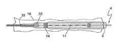
- FIG. 1is a plan view of the assembled device shown with an occluding ball wire 4 .
- the sheath 2is comprised of a sheath hub 5 , a distal tip section 6 , a lumen extending from the sheath hub 5 to the distal tip 6 and terminating in a sheath end hole 18 .
- the sheath hub 5may include a seal to prevent blood and sclerosant from leaking.
- the sheath 2 bodymay be reinforced with ultrasonically visible material such as braided or helically wound medical grade stainless steel wire. The reinforced shaft provides the user with enhanced flexibility and pushability in addition to improved visibility under ultrasound.
- the catheter component 3is coaxially arranged within the sheath lumen and is comprised of a catheter hub 8 , a distal tip 9 , and a lumen 10 extending from catheter hub 8 to the distal tip 9 and terminating in catheter end hole 19 . Extending along a portion of the catheter are pressure responsive exits or outlets 11 which form an infusion zone 20 , shown in FIGS. 2A and 2B .
- the maximum length of the infusion zone 20is identified by radiopaque markers 14 located at the distal and proximal end of the infusion zone.
- a standard Y-hub connector 24to provide a port for injecting the fluid sclerosant.
- a compression gasket 26such as a touhy-borst gasket is tightened around the guidewire to prevent drug leakage proximally.
- the distal tip of the catheter 3 and sheath 2may be designed to enhance visibility under fluoroscopy and/or ultrasound.
- the distal tip portion of catheter or sheathmay be loaded with tungsten or other radiopaque filler to increase the density whereby providing enhanced radiographic visibility.
- the distal tip of either componentmay be designed for enhanced visibility under ultrasound by incorporating structure to increase echogenicity.
- the tip of the sheathis visible under fluoroscopy and ultrasound so that, in conjunction with the distal marking on the catheter, the length of the infusion zone can be adjusted to match the treatment zone. Examples of such structures that will increase ultrasonic reflection include incorporating microspheres containing a gas into the tip, a band of braiding or other metallic material embedded within the tip and a tip containing an enclosed air space.
- the occluding ball of the occluding wire embodimentmay also be designed for enhanced visibility.
- Other methods of incorporating imaging visibility elements within the catheter and/or sheathare known within the art and are incorporated herein.
- FIG. 2Aillustrates a method in accordance with the device and technique described in U.S. Pat. No. 5,250,034 and U.S. Pat. No. 6,283,950.
- An occluding ball wire 4is comprised of a wire 34 , a distal hole occluding ball 32 , and a floppy distal end segment 36 which extends distally beyond the catheter end hole 19 .
- the occluding ball 32seats within the internal distal taper of the catheter, sealing and preventing fluid flow through the end hole.
- the occluding ball 32may be formed of echogenically visible material to enhance visibility of the catheter distal tip under ultrasound guidance.
- the Y-connector hub 24 shown in FIG. 1is connected to catheter hub 8 and is used to facilitate the delivery of sclerosant through the side arm 25 .
- the Y-connector hub 24may not be necessary if the occluding wire terminates within the body of the hub, as described in U.S. Pat. No. 6,283,950.
- the hubmay include a through lumen for the introduction of sclerosant fluid into the catheter lumen. In this occluding ball embodiment, the physician injects the sclerosant directly through occluding wire hub.
- FIG. 2Billustrates use of a standard guidewire 30 for occlusion of the catheter end hole 19 .
- the catheter end hole 19is dimensioned to fit snuggly against the outer diameter of the guidewire 30 , effectively occluding end hole 19 and creating an annular fluid channel 10 between the guidewire 30 and inner wall 12 of the catheter.
- a 5 French catheterhas a 0.067 inch outer diameter and a 0.048 inch inner diameter.
- the catheter lumentapers down distally to an end hole 19 having an inner diameter of approximately 0.036 inch to ensure occlusion by standard 0.035 inch guidewire.
- a 5 French sheathwould have dimensions of 0.085 inch outer and 0.068 inch inner diameters.
- the sheath tip 6would be sized to seal upon the catheter outer wall. Other dimensions are within the scope of this invention.
- the length of the catheteris dependent on the vein being treated. If the origin of reflux is associated with the Great Saphenous Vein for example, the vein segment being treated would typically range from 30-40 cm. A vein segment of this length would need a catheter with an infusion zone 20 of approximately 40 cm to ensure complete drug coverage of the vein wall.
- the sheath 2is retracted relative to the catheter 3 to uncover the desired length of the infusion zone 20 .
- a catheter measuring approximately 80 cm in lengthwould allow the sheath to be retracted the 40 cm needed to fully expose the entire infusion zone. Shorter catheters with shorter length infusion zones could be used to treat smaller length segments.
- the infusion zone 20is comprised of a pattern of pressure responsive outlets 11 which, by example, are each approximately 0.015 to 0.30 inch in length.
- a typical outlet patternincludes sets of four outlets located every 900 radially along the distal shaft of the catheter 3 .
- the outlets 11are approximately 5 mm apart in rows that are parallel to each other. Other outlet 11 dimensions and infusion zone patterns are within the scope of this invention.
- a syringe containing the sclerosant fluidis used to inject the fluid through the port 25 of the Y-hub connector 24 .
- the fluidflows through annular channel 10 exiting through those pressure responsive outlets 11 that are not covered by the sheath.
- the sheathalso functions to protect the insertion site track from the unintentional delivery of sclerosant into the adjacent tissue. Injection of sclerosant into tissue is known to cause tissue necrosis, which may lead to skin ulceration and other complications. If the user misaligns the catheter so that one or more outlets are within the insertion track yet outside of the vein, subsequent injection of sclerosant will flow through the outlets and penetrate the tissue immediately surrounding the insertion track. Because the distal end of the sheath is readily visible, placing the catheter through a sheath prevents this potential complication by ensuring that all outlets outside of the vein are covered by the sheath wall thus preventing sclerosant from being delivered externally to the vein. An introducer sheath can be employed to perform this protective function.
- the treatment procedurebegins with the standard pre-operative preparation of the patient as is well known in the treatment art.
- the patientis examined with ultrasound to identify and locate the source of venous reflux, typically the Great Saphenous Vein.
- Treatmentis not necessarily limited to the Great Saphenous Vein; diseased segments of the small saphenous vein and other veins may be treated using the improved method described herein.
- the sapheno-femoral junction and any anatomical variations of the venous systemare also identified during pre-treatment ultrasound. After the ultrasound examination, the patient's leg is draped and cleansed in preparation for the procedure.
- mapping of the veinis a very time-consuming step for the physician.
- the present inventionadvantageously minimizes the time spent mapping the vein since tumescent anesthesia is not required with the method of the current invention.
- tumescent anesthesiatypically involves making 10 to 20 needle punctures to deliver 10 to 20 perivenous injections under ultrasound guidance.
- the injectionsare time-consuming, can be painful to the patient, leave multiple puncture wounds and may increase bruising and post-procedure complications.
- the delivery of tumescent anesthesiais eliminated. Instead, only a small injection of local anesthesia is necessary at the entry site.
- the Great Saphenous Veinis accessed using a standard Seldinger technique.
- a small gauge needleis inserted through the skin and into the vein lumen.
- a guide wire 30is inserted through the needle and advanced to the sapheno-femoral junction.
- the entry needleis removed, leaving the guidewire 30 in place within the vein 16 , as shown in FIG. 3A .
- the sheath/catheter assembly 1is then advanced over the guidewire 30 into the vein and tracked over the wire until the assembly distal end is located just proximal of the sapheno-femoral junction.
- Advancement of the device 1 through tortuous vein segmentsis facilitated by the flexible material of the device which tracks through the curvature of the vessel lumen without kinking. Navigating through tortuous vessel segment is more difficult with prior art thermal treatment devices such as an RF electrode catheter or laser fiber, which are stiff and do not track as easily.
- the guidewire 30is removed.
- the occluding ball wire 4is then inserted through the catheter and advanced until the occluding ball 32 seats against the inner taper of the catheter distal tip, effectively sealing the distal end hole 19 , as shown in FIG. 3B .
- the guidewire 30remains in place within the lumen 10 of the catheter 3 during the procedure, such that the guidewire effectively occludes the end hole 19 , as previously illustrated in FIG. 2B .
- the placement of the catheter/sheath assembly within the vesselwill normally induce a significant and prolonged vein spasm.
- This spasmis desired and beneficial in that it will reduce the inner diameter of the vein being treated, which will cause a corresponding reduction in volume and flow of the blood in the vein.
- the reduction in blood volume of the target veinlimits the extent of dilution of the sclerosant while increasing the amount of drug that will reach the vessel wall.
- a vaso-constricting drugsuch as epinephrine may be injected intravenously through the catheter to induce vessel spasm.
- the sclerosantWith the distal end hole 19 of the catheter 3 occluded by either the occluding ball 32 or a guidewire 30 , the sclerosant is directed through the pressure responsive exits 11 in the catheter wall.
- This designthus decreases the probability that the sclerosant will migrate to the deep venous system by preventing a forward flowing jet of sclerosant from the distal end hole of the catheter.
- the sclerosantis prevented from traveling into the central system without the use of an occlusion balloon, manual compression or other adjunct occlusion devices or techniques.
- FIG. 3Cillustrates exposure of all outlets 11 in the infusion pattern.
- the usermay adjust the infusion pattern length by withdrawing the sheath 2 to selectively adjust the desired length of the infusion pattern.
- the sheath 2will prevent fluid flow through the covered outlets 11 because the fluid follows the path of least resistance and will exit from the non-covered outlets rather than the covered outlets.
- Radiopaque or ultrasonically visible markers 14may be provided on the catheter 3 to identify the distal and proximal ends of the maximum infusion outlet zone and on the distal tip 6 section of the sheath 2 to allow the user to discern the location of the sheath 2 relative to the outlet 11 pattern.
- the physicianmay pre-set the exposed infusion zone length prior to inserting the device into the vein.
- the cathetermay optionally contain markings along the shaft to assist in identifying the length of the exposed infusion zone.
- the sheath hub 5is aligned with a marking on the catheter that indicates the exposed infusion length. As an example, if a 10 cm infusion zone is desired, the physician aligns the sheath hub to the 10 cm marking on the catheter.
- a compression gasketmay be attached to the sheath hub to ensure that the catheter/sheath alignment remains stationary during insertion and advancement through the target vein.
- Sclerosantis delivered under pressure using a standard syringe attached to a Y-hub connector of the catheter 3 .
- Other delivery meansmay be used such as a pressurized reservoir of sclerosant.
- a sclerosantrefers to any fluid that acts upon the inner vessel wall causing a diameter reduction and subsequent vessel wall destruction and occlusion.
- Sclerosantsmay include solutions of hypertonic saline, polidocanol, sodium tetradecyl sulfate, chromated gylcerin, iodine and hypertonic glucose.
- Sclerosant fluid as defined hereinmay be liquid or foam in varying concentrations.
- the sclerosantmay also be combined with other adjunctive drugs such as vaso-spasming fluid, anesthetics, saline or other fluids.
- adjunctive drugsinclude but are not limited to ephrephrine, Lidocaine and Marcaine.
- Other sclerosants and adjunctive drugsalso fall within the scope of this invention.
- the drugmay be infused into the catheter 3 in a single bolus or multiple injections of small boluses. It is estimated that a small volume of drug, typically 0.2 cc per bolus, can effectively cover a vein segment of approximately 20 cm in length. Under forceful injections, the fluid advances into the annular fluid passageway 10 formed between the occluding ball wire 4 and the catheter 3 sidewall. Occlusion of the catheter 3 end hole 19 by occluding ball 32 causes the drug to exit from the exposed outlets 11 in the side wall of the catheter 3 into the vein 16 .
- outlets 11are of the same geometry and material and thus the pressure which will open each outlet 11 is the same.
- the pressure rise within the catheter lumen 10will be a uniform pressure on all outlets 11 .
- All outlets 11will open simultaneously at a predetermined internal pressure to allow the drug flow to exit from the catheter lumen 10 in a uniform manner along the entire length of the infusion pattern, as shown in FIG. 3D .
- the design and uniform spacing of the pressure responsive outlets 11ensures uniform and rapid delivery of the sclerosant fluid along the entire vein segment being treated. As illustrated in FIG. 3D , the pressure responsive outlets 11 direct the fluid jet 17 of the drug at a sufficient force to pass through the remaining blood to reach the vein wall without being materially diluted. Once it reaches the vessel wall, the sclerosant will disperse covering a larger area of the vein wall.
- the laminar flow of blood through the veinmeans that the velocity of flow varies from a maximum at the center of the vessel to a zero velocity at the vein wall.
- the near zero velocity of the blood flowis insufficient to dilute and wash away the drug from the walls.
- the design of this inventionmaximizes the vessel wall/drug contact by directing a high velocity drug column at a high angle (preferably close to 90 degrees) to the vessel wall.
- the high velocity drug columnis directed through the higher velocity blood flow toward the vessel wall where the blood flow is minimal and will not cause dilution of the drug.
- the effectiveness of methodis enhanced as the column of sclerosant approaches a 90 degree angle relative to the wall of the vessel.
- the vein wallwill further spasm as shown in FIGS. 3D and 3E , whereby further reducing the diameter of the vein.
- the physicianwill deliver single or multiple boluses of drug to the vein to achieve closure, depending on the length of the vein segment being treated.
- the recommended amount of sclerosant required to achieve permanent closure of the veinis based on inner vein wall surface area. Sufficient sclerosant must be infused to completely cover the vessel wall. Longer vein segments will require more sclerosant.
- the method of the current inventionis advantageous in that the drug is being delivered directly to the inner vein wall, with minimal or no dilution by the blood.
- the force of the fluid jet and its directed focus at the vessel wallprovide improved drug/wall coverage over prior art methods.
- the volume of fluid per jetis small but the velocity is high, providing a force capable of penetrating through the blood to contact the vessel wall.
- Significantly less drug volumeis required to achieve the desired impact than volumes required for an end hole catheter or direct injections which are directed into the blood stream where the drug is diluted by the blood flow.
- the methodis also advantageous over sclerotherapy devices that utilize porous material through which the drug is dispersed at lower velocity into the vein, resulting in less sclerosant reaching the vein wall.
- the method of this inventionmay include sequentially delivering sclerosant to segments of the vein.
- a shorter catheter or a catheter with a shorter infusion lengthmay be utilized.
- the sclerosantis first delivered through the catheter to the distal most segment of the vein.
- the catheteris repositioned proximally at the next segment to be treated and another injection is delivered to a new section of vein. This process is repeated until the entire length of the vein has been treated.
- a shorter length catheter deviceis easier to maneuver and control than a longer length catheter.
- a single devicecan be used to treat various lengths of vein. Thus, this method results in reduction of inventory that must be maintained by the medical facility.
- the catheter/sheath assembly 1is removed along with the occluding ball wire 4 , as illustrated in FIG. 3E .
- the access siteis then closed using method well known the art.
- the treated legis then wrapped in compression dressing and covered with a compression stocking to prevent any blood flow through the occluded vein.
- the method disclosed hereinprovides an effective means of treating varicosities with advantages over prior art treatment methods.
- the design and operation of the pressure responsive outlets 11provides an effective means of optimizing vessel wall/drug contact without manual emptying or isolation of the vein segment prior to the procedure.
- the use of tumescent anesthesia associated with thermal treatments such as RP or endovenous laser closureis eliminated using the method of this invention.
- Common complications of thermal treatmentsincluding vessel perforations, bruising, deep vein thrombosis and skin burns are avoided.
- the design of the catheter/sheath assemblyallows the physician to treat very tortuous vein segments, due to the flexibility and trackability of the catheter.
- a small volume of liquid drugcan be optimally administered directly to the vessel wall to achieve effective closure of a vessel.
- the procedure and method of this inventionis easy, uses an inexpensive, uncomplicated device and is fast, safe and effective.
- the sheath componentmay be omitted. Instead, a catheter is inserted over a guidewire and sclerosant is injected through the annular channel as described above.
- the infusion zone lengthcannot be varied with this embodiment, the elimination of the sheath component provides the user with a less expensive device that is simpler to use.
- catheters with different length infusion zonescan be used to accommodate different treatment segment lengths.
- a plurality of small exit holes located in the infusion zone of the catheter shaftmay be used to deliver the drug.
- the exit holesare each of a diameter sufficiently small to provide substantially the same velocity and volume of sclerosant through each exit in a uniform manner along the entire length of the infusion pattern.
- circular exits with a diameter of 0.0025′′ to 0.005′′ deployed circumferentially and longitudinally along the pre-determined infusion zonewill produce a jet of sclerosant at a sufficient force to pass through the remaining blood to reach the vein wall without being materially diluted.
- the exitsmay be formed using laser-cutting processes well known in the art.
- foam sclerosant compositionsmay provide sufficient flowability characteristics to be usable as a fluid in the method of this invention.
- foamsare compressible and will therefore create a lower velocity jet impinging on the vessel wall
- foam characteristics including bubble size and air to liquid ratiosmay be modified to optimize delivery through the device and method described herein whereby achieving the treatment goals of vein wall destruction and subsequent closure.
- foam sclerosantBy directing the foam sclerosant through the outlets on the side wall of the catheter at a substantially right angle relative to the vessel wall, smaller volumes of the foam sclerosant may be used with significantly less migration than would occur with an end hole catheter or injection needle.
- foam sclerosantBy controlling the migration of foam into the deep venous system, neurological and other treatment complications associated with gas-based sclerosants are minimized. Additionally, directing foam sclerosant through the outlets on the sidewall of the catheter allows the user to specifically target the treatment zone of the vessel.
Landscapes
- Health & Medical Sciences (AREA)
- Life Sciences & Earth Sciences (AREA)
- Surgery (AREA)
- Veterinary Medicine (AREA)
- General Health & Medical Sciences (AREA)
- Engineering & Computer Science (AREA)
- Biomedical Technology (AREA)
- Heart & Thoracic Surgery (AREA)
- Public Health (AREA)
- Animal Behavior & Ethology (AREA)
- Vascular Medicine (AREA)
- Nuclear Medicine, Radiotherapy & Molecular Imaging (AREA)
- Molecular Biology (AREA)
- Medical Informatics (AREA)
- Anesthesiology (AREA)
- Hematology (AREA)
- Biophysics (AREA)
- Pulmonology (AREA)
- Physics & Mathematics (AREA)
- Reproductive Health (AREA)
- Optics & Photonics (AREA)
- Electromagnetism (AREA)
- Otolaryngology (AREA)
- Surgical Instruments (AREA)
Abstract
Description
Claims (20)
Priority Applications (2)
| Application Number | Priority Date | Filing Date | Title |
|---|---|---|---|
| US14/989,167US9782562B2 (en) | 2002-04-04 | 2016-01-06 | Venous insufficiency treatment method |
| US15/270,562US20170106167A1 (en) | 2002-04-04 | 2016-09-20 | Venous insufficiency treatment method |
Applications Claiming Priority (4)
| Application Number | Priority Date | Filing Date | Title |
|---|---|---|---|
| US37005002P | 2002-04-04 | 2002-04-04 | |
| US10/393,922US7163533B2 (en) | 2002-04-04 | 2003-03-20 | Vascular treatment device and method |
| US11/303,818US9440046B2 (en) | 2002-04-04 | 2005-12-15 | Venous insufficiency treatment method |
| US14/989,167US9782562B2 (en) | 2002-04-04 | 2016-01-06 | Venous insufficiency treatment method |
Related Parent Applications (1)
| Application Number | Title | Priority Date | Filing Date |
|---|---|---|---|
| US11/303,818ContinuationUS9440046B2 (en) | 2002-04-04 | 2005-12-15 | Venous insufficiency treatment method |
Related Child Applications (1)
| Application Number | Title | Priority Date | Filing Date |
|---|---|---|---|
| US15/270,562ContinuationUS20170106167A1 (en) | 2002-04-04 | 2016-09-20 | Venous insufficiency treatment method |
Publications (2)
| Publication Number | Publication Date |
|---|---|
| US20160192944A1 US20160192944A1 (en) | 2016-07-07 |
| US9782562B2true US9782562B2 (en) | 2017-10-10 |
Family
ID=28678307
Family Applications (3)
| Application Number | Title | Priority Date | Filing Date |
|---|---|---|---|
| US11/303,818Expired - Fee RelatedUS9440046B2 (en) | 2002-04-04 | 2005-12-15 | Venous insufficiency treatment method |
| US14/989,167Expired - Fee RelatedUS9782562B2 (en) | 2002-04-04 | 2016-01-06 | Venous insufficiency treatment method |
| US15/270,562AbandonedUS20170106167A1 (en) | 2002-04-04 | 2016-09-20 | Venous insufficiency treatment method |
Family Applications Before (1)
| Application Number | Title | Priority Date | Filing Date |
|---|---|---|---|
| US11/303,818Expired - Fee RelatedUS9440046B2 (en) | 2002-04-04 | 2005-12-15 | Venous insufficiency treatment method |
Family Applications After (1)
| Application Number | Title | Priority Date | Filing Date |
|---|---|---|---|
| US15/270,562AbandonedUS20170106167A1 (en) | 2002-04-04 | 2016-09-20 | Venous insufficiency treatment method |
Country Status (1)
| Country | Link |
|---|---|
| US (3) | US9440046B2 (en) |
Cited By (1)
| Publication number | Priority date | Publication date | Assignee | Title |
|---|---|---|---|---|
| US20170106167A1 (en)* | 2002-04-04 | 2017-04-20 | Angiodynamics, Inc. | Venous insufficiency treatment method |
Families Citing this family (93)
| Publication number | Priority date | Publication date | Assignee | Title |
|---|---|---|---|---|
| US20030120256A1 (en)* | 2001-07-03 | 2003-06-26 | Syntheon, Llc | Methods and apparatus for sclerosing the wall of a varicose vein |
| GB0120645D0 (en) | 2001-08-24 | 2001-10-17 | Smiths Group Plc | Medico-surgical devices |
| US7458967B2 (en)* | 2003-10-31 | 2008-12-02 | Angiodynamics, Inc. | Endovascular treatment apparatus and method |
| EP2134282B1 (en) | 2002-07-10 | 2019-05-22 | AngioDynamics, Inc. | Device for endovascular treatment for causing closure of a blood vessel |
| GB0307350D0 (en) | 2003-03-29 | 2003-05-07 | Smiths Group Plc | Catheters |
| EP1781354A4 (en)* | 2004-08-19 | 2008-04-09 | Vein Rx Inc | An occludable intravascular catheter for drug delivery and method of using the same |
| KR20060072734A (en)* | 2004-12-23 | 2006-06-28 | 두산인프라코어 주식회사 | Compressed air supply device of construction equipment |
| CA2625824C (en)* | 2005-10-30 | 2013-12-17 | Medimop Medical Projects Ltd | Needleless additive control valve |
| CN101547653B (en) | 2006-09-13 | 2012-02-29 | 瓦斯库勒英赛特有限公司 | Vascular Therapy Devices |
| RU2326708C1 (en)* | 2006-12-27 | 2008-06-20 | Рустям Гиняятуллаевич Чаббаров | Method of pelvic limb reticular varix and telangiectasia treatment |
| US20080177186A1 (en)* | 2007-01-18 | 2008-07-24 | Slater Charles R | Methods and Apparatus for Determining a Treatment Volume of a Fluid Treatment Agent for Treating The Interior of a Blood Vessel |
| US20080200873A1 (en)* | 2007-02-16 | 2008-08-21 | Alejandro Espinosa | Methods and Apparatus for Infusing the Interior of a Blood Vessel |
| US9387308B2 (en)* | 2007-04-23 | 2016-07-12 | Cardioguidance Biomedical, Llc | Guidewire with adjustable stiffness |
| US8500697B2 (en)* | 2007-10-19 | 2013-08-06 | Pressure Products Medical Supplies, Inc. | Transseptal guidewire |
| US11589880B2 (en) | 2007-12-20 | 2023-02-28 | Angiodynamics, Inc. | System and methods for removing undesirable material within a circulatory system utilizing during a surgical procedure |
| US10517617B2 (en) | 2007-12-20 | 2019-12-31 | Angiodynamics, Inc. | Systems and methods for removing undesirable material within a circulatory system utilizing a balloon catheter |
| US20170136158A1 (en) | 2015-10-16 | 2017-05-18 | Angiodynamics, Inc. | Systems and Methods for Removing Undesirable Material Within a Circulatory System |
| US7963947B2 (en)* | 2008-01-16 | 2011-06-21 | Pressure Products Medical Supplies, Inc. | Apparatus, system, and method of shielding the sharp tip of a transseptal guidewire |
| US8157747B2 (en)* | 2008-02-15 | 2012-04-17 | Lary Research & Development, Llc | Single-use indicator for a surgical instrument and a surgical instrument incorporating same |
| CA2753207C (en)* | 2009-02-20 | 2017-07-11 | Sapheon, Inc. | Methods and devices for venous occlusion for the treatment of venous insufficiency |
| USD634007S1 (en)* | 2009-03-31 | 2011-03-08 | Medimop Medical Projects Ltd. | Needleless additive control valve |
| IL201323A0 (en) | 2009-10-01 | 2010-05-31 | Medimop Medical Projects Ltd | Fluid transfer device for assembling a vial with pre-attached female connector |
| IL202070A0 (en) | 2009-11-12 | 2010-06-16 | Medimop Medical Projects Ltd | Inline liquid drug medical device |
| DK2512398T3 (en) | 2010-02-24 | 2014-10-13 | Medimop Medical Projects Ltd | Liquid drug transfer device with vented ampoule adapter |
| DK2512399T3 (en) | 2010-02-24 | 2015-06-22 | Medimop Medical Projects Ltd | Fluid transfer device with vent arrangement |
| US10039900B2 (en)* | 2010-09-07 | 2018-08-07 | Angiodynamics, Inc. | Fluid delivery and treatment device and method of use |
| IL209290A0 (en) | 2010-11-14 | 2011-01-31 | Medimop Medical Projects Ltd | Inline liquid drug medical device having rotary flow control member |
| US9585667B2 (en) | 2010-11-15 | 2017-03-07 | Vascular Insights Llc | Sclerotherapy catheter with lumen having wire rotated by motor and simultaneous withdrawal from vein |
| EP2677961B1 (en) | 2011-02-24 | 2024-12-11 | Eximo Medical Ltd. | Hybrid catheter for vascular intervention |
| US12245788B2 (en) | 2011-03-15 | 2025-03-11 | Angiodynamics, Inc. | Device and method for removing material from a hollow anatomical structure |
| US9055964B2 (en) | 2011-03-15 | 2015-06-16 | Angio Dynamics, Inc. | Device and method for removing material from a hollow anatomical structure |
| IL212420A0 (en) | 2011-04-17 | 2011-06-30 | Medimop Medical Projects Ltd | Liquid drug transfer assembly |
| US8992513B2 (en) | 2011-06-30 | 2015-03-31 | Angiodynamics, Inc | Endovascular plasma treatment device and method of use |
| US8702678B2 (en)* | 2011-08-03 | 2014-04-22 | Venous Therapy, Inc. | Assemblies, systems, and methods for infusing therapeutic agents into the body |
| IL215699A0 (en) | 2011-10-11 | 2011-12-29 | Medimop Medical Projects Ltd | Liquid drug reconstitution assemblage for use with iv bag and drug vial |
| US20120109191A1 (en) | 2011-12-13 | 2012-05-03 | Vascular Insights Llc | Adhesive-based varicose vein treatment |
| USD737436S1 (en) | 2012-02-13 | 2015-08-25 | Medimop Medical Projects Ltd. | Liquid drug reconstitution assembly |
| USD720451S1 (en) | 2012-02-13 | 2014-12-30 | Medimop Medical Projects Ltd. | Liquid drug transfer assembly |
| WO2013123309A1 (en) | 2012-02-15 | 2013-08-22 | The Cleveland Clinic Foundation | Catheter assembly and method of treating a vascular disease |
| IL219065A0 (en) | 2012-04-05 | 2012-07-31 | Medimop Medical Projects Ltd | Fluid transfer device with manual operated cartridge release arrangement |
| IL221635A0 (en) | 2012-08-26 | 2012-12-31 | Medimop Medical Projects Ltd | Drug vial mixing and transfer device for use with iv bag and drug vial |
| IL221634A0 (en) | 2012-08-26 | 2012-12-31 | Medimop Medical Projects Ltd | Universal drug vial adapter |
| DK2872100T3 (en) | 2012-09-13 | 2017-07-10 | Medimop Medical Projects Ltd | Telescopic female adapter for drug ampoule |
| USD734868S1 (en) | 2012-11-27 | 2015-07-21 | Medimop Medical Projects Ltd. | Drug vial adapter with downwardly depending stopper |
| WO2014113257A2 (en) | 2013-01-15 | 2014-07-24 | A.V. Medical Technologies, Ltd. | Infusion catheter with guidewire valving |
| IL225734A0 (en) | 2013-04-14 | 2013-09-30 | Medimop Medical Projects Ltd | Ready-to-use drug vial assemblages including drug vial and drug vial closure having fluid transfer member, and drug vial closure therefor |
| CN105228676B (en) | 2013-05-10 | 2018-01-05 | 麦迪麦珀医疗工程有限公司 | Include the medical treatment device of the vial adapter with inline dry kit |
| AU2013101567B4 (en)* | 2013-05-27 | 2014-03-13 | P & M Hebbard Pty Ltd | A catheter system |
| USD765837S1 (en) | 2013-08-07 | 2016-09-06 | Medimop Medical Projects Ltd. | Liquid transfer device with integral vial adapter |
| USD767124S1 (en) | 2013-08-07 | 2016-09-20 | Medimop Medical Projects Ltd. | Liquid transfer device with integral vial adapter |
| DE212014000169U1 (en) | 2013-08-07 | 2016-03-14 | Medimop Medical Projects Ltd. | Fluid transfer devices for use with infusion fluid containers |
| WO2015088793A2 (en) | 2013-12-12 | 2015-06-18 | Mirizzi Michael S | Multiple chamber, expandable therapeutic agent delivery device |
| USD757933S1 (en) | 2014-09-11 | 2016-05-31 | Medimop Medical Projects Ltd. | Dual vial adapter assemblage |
| US20160096010A1 (en)* | 2014-10-02 | 2016-04-07 | AlgaMed Therapeutics | Applicator for application of a fluid substance within a body cavity and method of use thereof |
| JP6358724B2 (en) | 2015-01-05 | 2018-07-18 | ウエスト・ファーマ.サービシーズ・イスラエル,リミテッド | Dual vial adapter assembly with easy removable pill adapter to ensure accurate use |
| US11166729B2 (en)* | 2015-12-22 | 2021-11-09 | Basis Medical, Llc | Method and device for secluding a body vessel |
| WO2017009822A1 (en) | 2015-07-16 | 2017-01-19 | Medimop Medical Projects Ltd | Liquid drug transfer devices for secure telescopic snap fit on injection vials |
| USD801522S1 (en) | 2015-11-09 | 2017-10-31 | Medimop Medical Projects Ltd. | Fluid transfer assembly |
| CN115721558A (en) | 2015-11-25 | 2023-03-03 | 西部制药服务以色列有限公司 | Dual vial adapter assembly comprising a drug vial adapter having a self-sealing inlet valve |
| US11571217B2 (en)* | 2015-12-22 | 2023-02-07 | Basis Medical, Llc | Method and device for secluding a body vessel |
| CN109414292A (en) | 2016-05-05 | 2019-03-01 | 爱克斯莫医疗有限公司 | Device and method for cutting off and/or melting unwanted tissue |
| IL245803A0 (en) | 2016-05-24 | 2016-08-31 | West Pharma Services Il Ltd | Dual vial adapter assemblages including vented drug vial adapter and vented liquid vial adapter |
| IL245800A0 (en) | 2016-05-24 | 2016-08-31 | West Pharma Services Il Ltd | Dual vial adapter assemblages including identical twin vial adapters |
| IL246073A0 (en) | 2016-06-06 | 2016-08-31 | West Pharma Services Il Ltd | Fluid transfer devices for use with drug pump cartridge having slidable driving plunger |
| GB201612925D0 (en)* | 2016-07-26 | 2016-09-07 | Provensis Ltd | Method and device for generating injectable foam |
| IL247376A0 (en) | 2016-08-21 | 2016-12-29 | Medimop Medical Projects Ltd | Syringe assembly |
| US10328196B2 (en)* | 2016-10-13 | 2019-06-25 | The Cleveland Clinic Foundation | Systems and methods for peripheral vascular cannulation |
| USD832430S1 (en) | 2016-11-15 | 2018-10-30 | West Pharma. Services IL, Ltd. | Dual vial adapter assemblage |
| IL249408A0 (en) | 2016-12-06 | 2017-03-30 | Medimop Medical Projects Ltd | Liquid transfer device for use with infusion liquid container and pincers-like hand tool for use therewith for releasing intact drug vial therefrom |
| IL251458A0 (en) | 2017-03-29 | 2017-06-29 | Medimop Medical Projects Ltd | User actuated liquid drug transfer devices for use in ready-to-use (rtu) liquid drug transfer assemblages |
| US20180280671A1 (en)* | 2017-04-02 | 2018-10-04 | Christopher Parr | Device for treating venous incompetence, and related methods |
| IL254802A0 (en) | 2017-09-29 | 2017-12-31 | Medimop Medical Projects Ltd | Dual vial adapter assemblages with twin vented female vial adapters |
| EP3988074A1 (en) | 2017-12-03 | 2022-04-27 | West Pharma. Services IL, Ltd | Liquid transfer device with telescopic vial adapter for use with infusion liquid container and discrete injection vial |
| USD903864S1 (en) | 2018-06-20 | 2020-12-01 | West Pharma. Services IL, Ltd. | Medication mixing apparatus |
| JP1630477S (en) | 2018-07-06 | 2019-05-07 | ||
| USD923812S1 (en) | 2019-01-16 | 2021-06-29 | West Pharma. Services IL, Ltd. | Medication mixing apparatus |
| JP1648075S (en) | 2019-01-17 | 2019-12-16 | ||
| JP7209849B2 (en) | 2019-01-18 | 2023-01-20 | ウェスト・ファーマ・サービシーズ・アイエル・リミテッド | Liquid transfer device for use with IV bottles |
| US11918542B2 (en) | 2019-01-31 | 2024-03-05 | West Pharma. Services IL, Ltd. | Liquid transfer device |
| JP7284289B2 (en) | 2019-04-09 | 2023-05-30 | ウェスト ファーマ サービシーズ イスラエル リミテッド | Infusion device with integrated syringe |
| KR20240122586A (en) | 2019-04-30 | 2024-08-12 | 웨스트 파마. 서비시즈 일, 리미티드 | Liquid transfer device with dual lumen iv spike |
| US11364367B2 (en) | 2019-08-26 | 2022-06-21 | Covidien Lp | Medical fluid delivery |
| US12233219B2 (en)* | 2019-11-08 | 2025-02-25 | Hollister Incorporated | Methods of making sleeved and packaged hydrophilic catheter assemblies |
| US11648020B2 (en) | 2020-02-07 | 2023-05-16 | Angiodynamics, Inc. | Device and method for manual aspiration and removal of an undesirable material |
| US11666744B2 (en) | 2020-05-29 | 2023-06-06 | Basis Medical, Llc | Multi-lumen manifold and method of operating a multi-lumen manifold |
| USD956958S1 (en) | 2020-07-13 | 2022-07-05 | West Pharma. Services IL, Ltd. | Liquid transfer device |
| US12376904B1 (en) | 2020-09-08 | 2025-08-05 | Angiodynamics, Inc. | Dynamic laser stabilization and calibration system |
| US11696793B2 (en) | 2021-03-19 | 2023-07-11 | Crossfire Medical Inc | Vascular ablation |
| US12038322B2 (en) | 2022-06-21 | 2024-07-16 | Eximo Medical Ltd. | Devices and methods for testing ablation systems |
| US11980409B2 (en)* | 2022-08-08 | 2024-05-14 | Crossfire Medical Inc | Segmental vascular ablation |
| US20240149020A1 (en) | 2022-11-04 | 2024-05-09 | Controlled Delivery Systems, Inc. | Catheters for the aspiration controlled delivery of closure agents |
| EP4611658A1 (en) | 2022-11-04 | 2025-09-10 | Solvein Inc. | Catheters and related methods for aspiration and controlled delivery of closure agents |
| WO2024105430A1 (en)* | 2022-11-15 | 2024-05-23 | Fundacion Santa Fe De Bogota | Device for treating the saphenous vein and related varicose veins and a method for using same in the human body |
Citations (210)
| Publication number | Priority date | Publication date | Assignee | Title |
|---|---|---|---|---|
| US1706161A (en) | 1926-11-13 | 1929-03-19 | Gen Electric | Illuminating unit |
| US2699770A (en) | 1951-05-11 | 1955-01-18 | Centre Nat Rech Scient | Endoscope |
| US3043910A (en) | 1958-05-19 | 1962-07-10 | American Optical Corp | Fiber optical image transfer devices |
| US3051166A (en) | 1959-12-01 | 1962-08-28 | Avco Corp | Endoscope |
| US3051035A (en) | 1960-05-17 | 1962-08-28 | American Optical Corp | Flexible pyroscopes |
| US3068742A (en) | 1959-06-15 | 1962-12-18 | American Optical Corp | Means for performing colorimetry |
| US3423581A (en) | 1966-10-26 | 1969-01-21 | Gen Motors Corp | Remote illumination apparatus |
| US3455625A (en) | 1966-06-23 | 1969-07-15 | Bausch & Lomb | Optical fiber bundle coupling system |
| US3572325A (en) | 1968-10-25 | 1971-03-23 | Us Health Education & Welfare | Flexible endoscope having fluid conduits and control |
| US3605750A (en) | 1969-04-07 | 1971-09-20 | David S Sheridan | X-ray tip catheter |
| US3622743A (en) | 1969-04-28 | 1971-11-23 | Hrand M Muncheryan | Laser eraser and microwelder |
| US3641332A (en) | 1969-10-30 | 1972-02-08 | Ebert Michael | Fiber optics illumination system |
| US3643653A (en) | 1968-12-24 | 1972-02-22 | Olympus Optical Co | Endoscopic apparatus |
| US3678741A (en) | 1971-03-24 | 1972-07-25 | Gen Motors Corp | Engine combustion monitor |
| US3704996A (en) | 1969-10-23 | 1972-12-05 | Licentia Gmbh | Optical coupling arrangement |
| US3710798A (en) | 1971-08-30 | 1973-01-16 | American Optical Corp | Laser system for microsurgery |
| US3726272A (en) | 1967-09-21 | 1973-04-10 | Olympus Optical Co | Endoscope |
| US3756688A (en) | 1972-03-30 | 1973-09-04 | Corning Glass Works | Metallized coupler for optical waveguide light source |
| US3768146A (en) | 1972-02-22 | 1973-10-30 | Bell Telephone Labor Inc | Method of splicing optical fibers |
| US3780295A (en) | 1972-03-30 | 1973-12-18 | Corning Glass Works | Light source coupler for optical waveguide |
| US3790791A (en) | 1972-07-20 | 1974-02-05 | Bunker Ramo | Optoelectronic cable assembly |
| US3796905A (en) | 1971-11-10 | 1974-03-12 | Matsushita Electric Industrial Co Ltd | Cathode-ray tube having prism-shaped fibre optics faceplate |
| US3808549A (en) | 1972-03-30 | 1974-04-30 | Corning Glass Works | Optical waveguide light source |
| US3832028A (en) | 1972-03-30 | 1974-08-27 | Corning Glass Works | Coupler for optical waveguide light source |
| US3834803A (en) | 1972-04-05 | 1974-09-10 | Canon Kk | Photo-information transmission and exposure device |
| US3834391A (en) | 1973-01-19 | 1974-09-10 | Block Carol Ltd | Method and apparatus for photoepilation |
| US3843865A (en) | 1971-09-14 | 1974-10-22 | G Nath | Device for material working by a laser beam,and method for its production |
| US3846010A (en) | 1973-07-05 | 1974-11-05 | Corning Glass Works | Optical waveguide connector |
| US3849947A (en) | 1973-07-16 | 1974-11-26 | Bunker Ramo | Methods of squaring elements with a surface in which they are mounted |
| US3858577A (en) | 1974-04-05 | 1975-01-07 | Univ Southern California | Fiber optic laser light delivery system |
| US3861781A (en) | 1972-10-23 | 1975-01-21 | Nippon Electric Co | Separable optical fiber connector and the method of manufacturing the same |
| US3866599A (en) | 1972-01-21 | 1975-02-18 | Univ Washington | Fiberoptic catheter |
| US3874783A (en) | 1972-08-02 | 1975-04-01 | American Optical Corp | Numerical aperture expansion in fiber optic devices |
| US3880452A (en) | 1972-04-27 | 1975-04-29 | Robert E Fields | Connectors |
| US3906221A (en) | 1973-12-10 | 1975-09-16 | Gary M Mercier | Proof of igniter and flame sensing device and system |
| US3910677A (en) | 1974-05-13 | 1975-10-07 | Bell Telephone Labor Inc | Hyperbolic type optical fiber lens coupler for coupling the fiber to an optical line source |
| US3920980A (en) | 1974-07-18 | 1975-11-18 | Nath Guenther | Flexible light guide |
| US3932184A (en) | 1973-05-29 | 1976-01-13 | Bell Telephone Laboratories, Incorporated | Fabrication of microlenses |
| US3972585A (en) | 1975-02-13 | 1976-08-03 | Northern Electric Company Limited | Connectors for optical fibers |
| US4005522A (en) | 1975-02-13 | 1977-02-01 | Northern Telecom Limited | Method of connecting two optical fibres in end to end relationship |
| US4008948A (en) | 1975-06-30 | 1977-02-22 | Northern Telecom Limited | Optical fibre connectors |
| US4087158A (en) | 1976-12-06 | 1978-05-02 | The United States Of America As Represented By The Secretary Of The Navy | Low-loss single filament fiber optic connector with three concentric tapered members for each filaments |
| GB1533204A (en) | 1976-09-07 | 1978-11-22 | Leveen H | Flexible tubing |
| US4148554A (en) | 1977-08-05 | 1979-04-10 | Minnesota Mining And Manufacturing Company | Method of providing recessed optical fiber ends for use in connector structures |
| US4191446A (en) | 1974-12-16 | 1980-03-04 | U.S. Philips Corporation | Directional coupling-device for multi-mode optical fibres |
| US4233493A (en) | 1974-05-21 | 1980-11-11 | Nath Guenther | Apparatus for applying intense light radiation to a limited area |
| US4273109A (en) | 1976-07-06 | 1981-06-16 | Cavitron Corporation | Fiber optic light delivery apparatus and medical instrument utilizing same |
| US4313431A (en) | 1978-12-06 | 1982-02-02 | Messerschmitt-Boelkow-Blohm Gesellschaft Mit Beschraenkter Haftung | Endoscopic apparatus with a laser light conductor |
| US4380365A (en) | 1978-05-23 | 1983-04-19 | Battelle Memorial Institute | Optical fiber, having on at least one of its frontal extremities a plano-convex microlens joined with its plane face to said frontal extremity |
| US4449535A (en) | 1981-03-25 | 1984-05-22 | Compagnie Industrielle Des Lasers Cilas Alcatel | Apparatus for measuring in situ the state of oxidation-reduction of a living organ |
| US4564011A (en) | 1982-03-22 | 1986-01-14 | Leon Goldman | Laser optic device and method |
| US4573761A (en) | 1983-09-14 | 1986-03-04 | The Dow Chemical Company | Fiber-optic probe for sensitive Raman analysis |
| US4578061A (en) | 1980-10-28 | 1986-03-25 | Lemelson Jerome H | Injection catheter and method |
| US4592353A (en) | 1984-05-22 | 1986-06-03 | Surgical Laser Technologies Ohio, Inc. | Medical and surgical laser probe |
| US4654532A (en) | 1985-09-09 | 1987-03-31 | Ord, Inc. | Apparatus for improving the numerical aperture at the input of a fiber optics device |
| US4660925A (en) | 1985-04-29 | 1987-04-28 | Laser Therapeutics, Inc. | Apparatus for producing a cylindrical pattern of light and method of manufacture |
| US4662368A (en) | 1983-06-13 | 1987-05-05 | Trimedyne Laser Systems, Inc. | Localized heat applying medical device |
| US4666426A (en) | 1984-01-12 | 1987-05-19 | Karl Aigner | Double lumen catheter for a device for in-vivo purification of blood |
| US4671273A (en) | 1984-03-19 | 1987-06-09 | Lindsey Ernest J | Laser hand piece, for use in opthalmic, plastic, and ear, nose, and throat surgery |
| US4693556A (en) | 1985-06-04 | 1987-09-15 | Laser Therapeutics, Inc. | Apparatus for producing a spherical pattern of light and method of manufacture |
| US4693244A (en) | 1984-05-22 | 1987-09-15 | Surgical Laser Technologies, Inc. | Medical and surgical laser probe I |
| US4695697A (en) | 1985-12-13 | 1987-09-22 | Gv Medical, Inc. | Fiber tip monitoring and protection assembly |
| US4697595A (en) | 1984-07-24 | 1987-10-06 | Telectronics N.V. | Ultrasonically marked cardiac catheters |
| US4707134A (en) | 1984-12-04 | 1987-11-17 | The Dow Chemical Company | Fiber optic probe |
| US4736743A (en) | 1986-05-12 | 1988-04-12 | Surgical Laser Technology, Inc. | Vaporization contact laser probe |
| US4740047A (en) | 1985-03-26 | 1988-04-26 | Hatachi Cable, Ltd. | Fiber for lateral beaming of laser beam |
| US4743084A (en) | 1986-05-14 | 1988-05-10 | Amp Incorporated | Optical fiber connector for field application |
| US4773413A (en) | 1983-06-13 | 1988-09-27 | Trimedyne Laser Systems, Inc. | Localized heat applying medical device |
| US4802650A (en) | 1987-06-29 | 1989-02-07 | Abiomed, Inc. | Intravenous drug mixing and flow device |
| US4812003A (en) | 1987-11-10 | 1989-03-14 | Molex Incorporated | Optic sensing assembly |
| US4816670A (en) | 1986-09-19 | 1989-03-28 | Godai Embody Co., Ltd. | Optical measuring head |
| US4817601A (en) | 1985-03-06 | 1989-04-04 | C. R. Bard, Inc. | Catheter system for controlled removal by radiant energy of biological obstructions |
| EP0311295A2 (en) | 1987-10-07 | 1989-04-12 | University College London | Improvements in surgical apparatus |
| US4834493A (en) | 1985-12-27 | 1989-05-30 | Mcdonnell Douglas Corporation | Method of terminating an optical fiber |
| DE8905642U1 (en) | 1989-05-05 | 1989-08-10 | REHAU AG + Co, 8673 Rehau | Catheter tube |
| US4862887A (en) | 1987-05-29 | 1989-09-05 | Gesellschaft Fuer Strahlen Und Umweltforschung (Gsf) | Heart catheter |
| US4889129A (en) | 1982-09-27 | 1989-12-26 | Health Research, Inc. | Apparatus for treatment of tumors |
| US4968306A (en) | 1989-07-07 | 1990-11-06 | Advanced Cardiovascular Systems, Inc. | Intravascular catheter having an adjustable length infusion section to delivery therapeutic fluid |
| US4979797A (en) | 1989-10-06 | 1990-12-25 | Imo Industries, Inc. | Multi-level fiber-optic liquid-level sensing system |
| US4985029A (en) | 1989-01-11 | 1991-01-15 | Masahiko Hoshino | Laser apparatus for medical treatment |
| US4988163A (en) | 1989-08-17 | 1991-01-29 | Quantronix Corp. | Infrared laser system for surgical purposes employing compound fiber probe |
| US4995691A (en) | 1989-10-16 | 1991-02-26 | Ensign-Bickford Optics Company | Angled optical fiber input end face and method for delivering energy |
| US5011279A (en) | 1987-06-13 | 1991-04-30 | Basf Aktiengesellschaft | Fiber-optical sensor |
| US5011254A (en) | 1989-11-30 | 1991-04-30 | At&T Bell Laboratories | Coupling of optical devices to optical fibers by means of microlenses |
| US5026366A (en) | 1984-03-01 | 1991-06-25 | Cardiovascular Laser Systems, Inc. | Angioplasty catheter and method of use thereof |
| US5030201A (en) | 1989-11-24 | 1991-07-09 | Aubrey Palestrant | Expandable atherectomy catheter device |
| US5037421A (en) | 1989-10-06 | 1991-08-06 | Coherent, Inc., Medical Group | Mid-infrared laser arthroscopic procedure |
| US5037180A (en) | 1990-07-19 | 1991-08-06 | At&T Bell Laboratories | Optical filter on optical fiber end face |
| US5041109A (en) | 1986-10-27 | 1991-08-20 | University Of Florida | Laser apparatus for the recanalization of vessels and the treatment of other cardiac conditions |
| US5042980A (en) | 1989-05-26 | 1991-08-27 | C. R. Bard, Inc. | Optical fiber diffusion tip for uniform illumination |
| US5074632A (en) | 1990-03-07 | 1991-12-24 | Health Research, Inc. | Fiber optic diffusers and methods for manufacture of the same |
| US5093877A (en) | 1990-10-30 | 1992-03-03 | Advanced Cardiovascular Systems | Optical fiber lasing apparatus lens |
| US5100507A (en) | 1991-01-31 | 1992-03-31 | At&T Bell Laboratories | Finishing techniques for lensed optical fibers |
| US5112127A (en) | 1989-11-28 | 1992-05-12 | Eic Laboratories, Inc. | Apparatus for measuring Raman spectra over optical fibers |
| US5129896A (en) | 1989-11-13 | 1992-07-14 | Hasson Harrith M | Holder to facilitate use of a laser in surgical procedures |
| WO1992014515A1 (en) | 1991-02-19 | 1992-09-03 | Advanced Interventional Systems, Inc. | Delivery system for pulsed excimer laser light |
| US5147354A (en) | 1988-08-19 | 1992-09-15 | Coherent, Inc. | Mid-infrared laser endoscope |
| US5146917A (en) | 1990-01-09 | 1992-09-15 | Ciba-Geigy Corporation | Fibre-optic apparatus for the photodynamic treatment of tumors |
| US5147353A (en) | 1990-03-23 | 1992-09-15 | Myriadlase, Inc. | Medical method for applying high energy light and heat for gynecological sterilization procedures |
| US5151096A (en) | 1991-03-28 | 1992-09-29 | Angiolaz, Incorporated | Laser catheter diffuser |
| US5154708A (en) | 1990-05-15 | 1992-10-13 | Surgical Laser Technologies, Inc. | Unitary scalpel for contact laser surgery |
| US5164945A (en) | 1991-07-01 | 1992-11-17 | Laser Centers Of America, Inc. | Laser device with intermediate refraction index layer for reduced fresnel losses |
| US5166756A (en) | 1990-11-28 | 1992-11-24 | Nir Systems Incorporated | Powder fiber optic probe having angled end in nir optical analyzing instrument |
| US5188635A (en) | 1988-02-08 | 1993-02-23 | Wolfgang Radtke | Catheter for percutaneous surgery of blood vessels and organs using radiant energy |
| US5190536A (en) | 1988-11-08 | 1993-03-02 | Health Research, Inc. | Submersible lens fiberoptic assembly for use in PDT treatment |
| US5193526A (en) | 1989-09-05 | 1993-03-16 | S.L.T. Japan Co., Ltd. | Laser light irradiation apparatus |
| US5196005A (en) | 1991-11-26 | 1993-03-23 | Pdt Systems, Inc. | Continuous gradient cylindrical diffusion tip for optical fibers and method for making |
| US5207669A (en) | 1989-05-26 | 1993-05-04 | C. R. Bard, Inc. | Optical fiber diffusion tip for uniform illumination |
| US5253312A (en) | 1992-06-26 | 1993-10-12 | Cytocare, Inc. | Optical fiber tip for use in a laser delivery system and a method for forming same |
| US5254114A (en) | 1991-08-14 | 1993-10-19 | Coherent, Inc. | Medical laser delivery system with internally reflecting probe and method |
| US5263951A (en) | 1989-04-21 | 1993-11-23 | Kerus Medical Systems | Correction of the optical focusing system of the eye using laser thermal keratoplasty |
| US5263952A (en) | 1992-03-25 | 1993-11-23 | Spectranetics | Two-piece tip for fiber optic catheter |
| US5267979A (en)* | 1990-09-17 | 1993-12-07 | E-Z-Em, Inc. | Pressure responsive valve catheter |
| US5267995A (en) | 1992-09-01 | 1993-12-07 | Pdt Systems | Optical waveguide with flexible tip |
| US5269777A (en) | 1990-11-01 | 1993-12-14 | Pdt Systems, Inc. | Diffusion tip for optical fibers |
| US5275622A (en) | 1983-12-09 | 1994-01-04 | Harrison Medical Technologies, Inc. | Endovascular grafting apparatus, system and method and devices for use therewith |
| US5290275A (en) | 1985-03-22 | 1994-03-01 | Massachusetts Institute Of Technology | Catheter for laser angiosurgery |
| US5292320A (en) | 1992-07-06 | 1994-03-08 | Ceramoptec, Inc. | Radial medical laser delivery device |
| US5292311A (en) | 1989-01-31 | 1994-03-08 | Cook Incorporated | Recessed dilator-sheath assembly and method |
| US5300066A (en) | 1990-02-07 | 1994-04-05 | Coherent, Inc. | Contact laser delivery system |
| US5306274A (en) | 1991-12-23 | 1994-04-26 | Laser Centers Of America | Laser-powered high temperature energy delivery tip element with throughflow of vaporized materials and electrocauterization capability |
| US5342383A (en) | 1992-03-27 | 1994-08-30 | Thomas Medical Products, Inc. | Soft tip obturator |
| US5343543A (en) | 1993-05-27 | 1994-08-30 | Heraeus Surgical, Inc. | Side-firing laser fiber with directional indicator and methods of use in determining the orientation of radiation to be emitted from the side-firing laser fiber |
| US5349590A (en) | 1992-04-10 | 1994-09-20 | Premier Laser Systems, Inc. | Medical laser apparatus for delivering high power infrared light |
| US5352221A (en) | 1992-11-04 | 1994-10-04 | Fumich Robert M | Guide tip apparatus for laser surgery |
| US5354294A (en) | 1993-05-26 | 1994-10-11 | Xintec Corporation | Combination reflectance fiber optic laser beam angle delivery |
| US5360416A (en) | 1993-09-30 | 1994-11-01 | Sherwood Medical Company | Thin-walled anesthesia needles |
| US5370649A (en) | 1991-08-16 | 1994-12-06 | Myriadlase, Inc. | Laterally reflecting tip for laser transmitting fiber |
| US5402508A (en) | 1993-05-04 | 1995-03-28 | The United States Of America As Represented By The United States Department Of Energy | Fiber optic probe having fibers with endfaces formed for improved coupling efficiency and method using same |
| US5401270A (en) | 1990-12-19 | 1995-03-28 | Carl-Zeiss-Stiftung | Applicator device for laser radiation |
| US5404218A (en) | 1993-11-18 | 1995-04-04 | The United States Of America As Represented By The United States Department Of Energy | Fiber optic probe for light scattering measurements |
| US5415655A (en) | 1992-04-24 | 1995-05-16 | Surgical Laser Technologies, Inc. | Medical device including light energy emitting contact tip with means for raising temperature of the tip |
| US5419312A (en) | 1993-04-20 | 1995-05-30 | Wildflower Communications, Inc. | Multi-function endoscope apparatus |
| US5421928A (en) | 1994-07-01 | 1995-06-06 | Siecor Corporation | Laser removal of excess optical fiber prior to connector polishing |
| US5425723A (en)* | 1993-12-30 | 1995-06-20 | Boston Scientific Corporation | Infusion catheter with uniform distribution of fluids |
| US5428699A (en) | 1993-07-02 | 1995-06-27 | Laserscope | Probe having optical fiber for laterally directing laser beam |
| US5432880A (en) | 1994-03-17 | 1995-07-11 | At&T Corp. | Angled optical connector ferrule |
| US5445608A (en) | 1993-08-16 | 1995-08-29 | James C. Chen | Method and apparatus for providing light-activated therapy |
| US5456680A (en) | 1993-09-14 | 1995-10-10 | Spectranetics Corp | Fiber optic catheter with shortened guide wire lumen |
| US5464395A (en) | 1994-04-05 | 1995-11-07 | Faxon; David P. | Catheter for delivering therapeutic and/or diagnostic agents to the tissue surrounding a bodily passageway |
| US5495541A (en) | 1994-04-19 | 1996-02-27 | Murray; Steven C. | Optical delivery device with high numerical aperture curved waveguide |
| US5499975A (en) | 1989-01-31 | 1996-03-19 | Cook Incorporated | Smooth transitioned dilator-sheath assembly and method |
| US5509917A (en) | 1994-06-28 | 1996-04-23 | Ceramoptec Industries, Inc. | Lensed caps for radial medical laser delivery devices |
| US5534000A (en) | 1994-03-17 | 1996-07-09 | Endeavor Surgical Products, Inc. | Laser fiber apparatus having a contact tip and adjacent diffuser element and surgical methods for using same |
| US5536265A (en) | 1994-03-25 | 1996-07-16 | Ciba-Geigy Corporation | Light diffuser and process for the manufacturing of a light diffuser |
| US5562657A (en) | 1994-09-19 | 1996-10-08 | Griffin; Stephen E. | Side fire laser catheter method and apparatus |
| US5631986A (en) | 1994-04-29 | 1997-05-20 | Minnesota Mining And Manufacturing Co. | Optical fiber ferrule |
| US5643257A (en) | 1994-01-18 | 1997-07-01 | Endovascular, Inc. | Apparatus and method for venous ligation |
| US5643251A (en) | 1992-08-18 | 1997-07-01 | Spectranetics Corporation | Fibert optic guide wire and support catheter therefor |
| US5643253A (en) | 1995-06-06 | 1997-07-01 | Rare Earth Medical, Inc. | Phototherapy apparatus with integral stopper device |
| US5688263A (en) | 1994-12-22 | 1997-11-18 | Dornier Medizintechnik Gmbh | Laser surgery applicator |
| US5693029A (en) | 1995-07-10 | 1997-12-02 | World Medical Manufacturing Corporation | Pro-cell intra-cavity therapeutic agent delivery device |
| US5693043A (en) | 1985-03-22 | 1997-12-02 | Massachusetts Institute Of Technology | Catheter for laser angiosurgery |
| US5695482A (en) | 1991-07-23 | 1997-12-09 | Intermed, Inc. | UV treated catheter |
| US5700243A (en) | 1992-10-30 | 1997-12-23 | Pdt Systems, Inc. | Balloon perfusion catheter |
| US5710626A (en) | 1996-11-15 | 1998-01-20 | Westinghouse Savannah River Company | Rugged fiber optic probe for raman measurement |
| US5717807A (en) | 1995-07-14 | 1998-02-10 | United States Surgical Corporation | Liquid light guide with improved sealing characteristics |
| US5725521A (en) | 1996-03-29 | 1998-03-10 | Eclipse Surgical Technologies, Inc. | Depth stop apparatus and method for laser-assisted transmyocardial revascularization and other surgical applications |
| US5728091A (en) | 1995-06-07 | 1998-03-17 | Cardiogenesis Corporation | Optical fiber for myocardial channel formation |
| US5754717A (en) | 1995-10-31 | 1998-05-19 | Indigo Medical, Incorporated | Light-diffusing device for an optical fiber, methods of producing and using same, and apparatus for diffusing light from an optical fiber |
| US5764840A (en) | 1995-11-20 | 1998-06-09 | Visionex, Inc. | Optical fiber with enhanced light collection and illumination and having highly controlled emission and acceptance patterns |
| US5769868A (en) | 1986-04-15 | 1998-06-23 | Yock; Paul G. | Angioplasty apparatus facilitating rapid exchanges |
| US5782797A (en) | 1996-06-06 | 1998-07-21 | Scimed Life Systems, Inc. | Therapeutic infusion device |
| US5817144A (en) | 1994-10-25 | 1998-10-06 | Latis, Inc. | Method for contemporaneous application OF laser energy and localized pharmacologic therapy |
| US5836940A (en) | 1994-10-25 | 1998-11-17 | Latis, Inc. | Photoacoustic drug delivery |
| US5843073A (en) | 1985-07-31 | 1998-12-01 | Rare Earth Medical, Inc. | Infrared laser catheter system |
| US5868734A (en) | 1995-11-29 | 1999-02-09 | Iowa State University Research Foundation, Inc. | Methods of using silica-titania clad fibers |
| US5897551A (en) | 1990-03-23 | 1999-04-27 | Myriadlase, Inc. | Medical device for applying high energy light and heat for gynecological sterilization procedures |
| US5908415A (en) | 1994-09-09 | 1999-06-01 | Rare Earth Medical, Inc. | Phototherapy methods and apparatus |
| US5947959A (en) | 1994-09-09 | 1999-09-07 | Rare Earth Medical, Inc. | Phototherapeutic apparatus with diffusive tip assembly |
| US5991404A (en) | 1996-07-15 | 1999-11-23 | Schlumberger Industries, S.A. | System for diversifying information in a network for distributing goods or services |
| US6033398A (en) | 1996-03-05 | 2000-03-07 | Vnus Medical Technologies, Inc. | Method and apparatus for treating venous insufficiency using directionally applied energy |
| US6056743A (en) | 1997-11-04 | 2000-05-02 | Scimed Life Systems, Inc. | Percutaneous myocardial revascularization device and method |
| US6102905A (en) | 1994-09-09 | 2000-08-15 | Cardiofocus, Inc. | Phototherapy device including housing for an optical element and method of making |
| US6117125A (en) | 1996-05-02 | 2000-09-12 | Cook Incorporated | Method for predetermining uniform flow rate of a fluid from a tubular body and device therefrom |
| US6126654A (en) | 1997-04-04 | 2000-10-03 | Eclipse Surgical Technologies, Inc. | Method of forming revascularization channels in myocardium using a steerable catheter |
| US20010001314A1 (en) | 1997-06-13 | 2001-05-17 | Arthrocare Corporation | Electrosurgical systems and methods for recanalization of occluded body lumens |
| US6251100B1 (en) | 1993-09-24 | 2001-06-26 | Transmedica International, Inc. | Laser assisted topical anesthetic permeation |
| US6258084B1 (en) | 1997-09-11 | 2001-07-10 | Vnus Medical Technologies, Inc. | Method for applying energy to biological tissue including the use of tumescent tissue compression |
| US6263236B1 (en) | 1999-11-29 | 2001-07-17 | Illumenex Corporation | Non-occlusive expandable catheter |
| US6270495B1 (en) | 1996-02-22 | 2001-08-07 | Radiotherapeutics Corporation | Method and device for enhancing vessel occlusion |
| US6270492B1 (en) | 1994-09-09 | 2001-08-07 | Cardiofocus, Inc. | Phototherapeutic apparatus with diffusive tip assembly |
| US6283951B1 (en) | 1996-10-11 | 2001-09-04 | Transvascular, Inc. | Systems and methods for delivering drugs to selected locations within the body |
| US6344048B1 (en) | 1997-07-10 | 2002-02-05 | Scimed Life Systems, Inc. | Removable occlusion system for aneurysm neck |
| US6375651B2 (en) | 1999-02-19 | 2002-04-23 | Scimed Life Systems, Inc. | Laser lithotripsy device with suction |
| US6398777B1 (en) | 1999-02-01 | 2002-06-04 | Luis Navarro | Endovascular laser device and treatment of varicose veins |
| US20020072680A1 (en) | 2000-12-12 | 2002-06-13 | Schock Robert B. | Intra-aortic balloon catheter having a fiberoptic sensor |
| US6447477B2 (en) | 1996-02-09 | 2002-09-10 | Emx, Inc. | Surgical and pharmaceutical site access guide and methods |
| US20020183729A1 (en) | 1999-07-14 | 2002-12-05 | Farr Norman E. | Phototherapeutic wave guide apparatus |
| US6522806B1 (en) | 2001-02-16 | 2003-02-18 | Ethicon Endo-Surgury, Inc. | Optical fiber including a diffuser portion and continuous sleeve for the transmission of light |
| US20030050686A1 (en) | 1999-05-14 | 2003-03-13 | Raeder-Devens Jennifer E. | Prosthesis deployment device with translucent distal end |
| US6551302B1 (en) | 1997-09-24 | 2003-04-22 | Michael J. Rosinko | Steerable catheter with tip alignment and surface contact detector |
| US20030078568A1 (en) | 2001-06-15 | 2003-04-24 | Diomed Inc. | Medical laser device |
| US6555827B1 (en) | 1996-08-10 | 2003-04-29 | Dieter Kockott | Method of determining variations in the properties of a sample |
| US6561998B1 (en) | 1998-04-07 | 2003-05-13 | Transvascular, Inc. | Transluminal devices, systems and methods for enlarging interstitial penetration tracts |
| US20030120256A1 (en)* | 2001-07-03 | 2003-06-26 | Syntheon, Llc | Methods and apparatus for sclerosing the wall of a varicose vein |
| US20030191460A1 (en) | 2002-04-04 | 2003-10-09 | Angiodynamics, Inc. | Vascular treatment device and method |
| US6692466B1 (en) | 2000-12-21 | 2004-02-17 | Advanced Cardiovascular Systems, Inc. | Drug delivery catheter with retractable needle |
| US6767338B2 (en) | 2000-10-24 | 2004-07-27 | Scimed Life Systems, Inc. | Variable tip catheter |
| US6769433B2 (en) | 1997-09-11 | 2004-08-03 | Vnus Medical Technologies, Inc. | Expandable vein ligator catheter having multiple electrode leads, and method |
| US6796710B2 (en) | 2001-06-08 | 2004-09-28 | Ethicon Endo-Surgery, Inc. | System and method of measuring and controlling temperature of optical fiber tip in a laser system |
| US20050107738A1 (en)* | 2000-07-21 | 2005-05-19 | Slater Charles R. | Occludable intravascular catheter for drug delivery and method of using the same |
| US20050113798A1 (en)* | 2000-07-21 | 2005-05-26 | Slater Charles R. | Methods and apparatus for treating the interior of a blood vessel |
| US6926692B2 (en) | 2002-03-05 | 2005-08-09 | Osamu Katoh | Medicinal liquid injection catheter |
| US6962584B1 (en) | 2001-09-06 | 2005-11-08 | Stone Gregg W | Electromagnetic photonic catheter for reducing restenosis |
| US6986766B2 (en) | 2001-06-15 | 2006-01-17 | Diomed Inc. | Method of endovenous laser treatment |
| US6989004B2 (en) | 2001-02-28 | 2006-01-24 | Rex Medical, L.P. | Apparatus for delivering ablation fluid to treat lesions |
| US20060095015A1 (en) | 2002-04-04 | 2006-05-04 | Angiodynamics, Inc. | Venous insufficiency treatment method |
| US7912554B2 (en) | 2001-09-26 | 2011-03-22 | Medtronic Cryocath Lp | Method for treatment of aneurysms |
| US8291915B2 (en) | 1997-03-04 | 2012-10-23 | Tyco Healthcare Group Lp | Method and apparatus for treating venous insufficiency using directionally applied energy |
Family Cites Families (4)
| Publication number | Priority date | Publication date | Assignee | Title |
|---|---|---|---|---|
| US5250034A (en) | 1990-09-17 | 1993-10-05 | E-Z-Em, Inc. | Pressure responsive valve catheter |
| US5246437A (en) | 1992-04-10 | 1993-09-21 | Abela George S | Cell treatment apparatus and method |
| US5464404A (en) | 1993-09-20 | 1995-11-07 | Abela Laser Systems, Inc. | Cardiac ablation catheters and method |
| US5999678A (en) | 1996-12-27 | 1999-12-07 | Eclipse Surgical Technologies, Inc. | Laser delivery means adapted for drug delivery |
- 2005
- 2005-12-15USUS11/303,818patent/US9440046B2/ennot_activeExpired - Fee Related
- 2016
- 2016-01-06USUS14/989,167patent/US9782562B2/ennot_activeExpired - Fee Related
- 2016-09-20USUS15/270,562patent/US20170106167A1/ennot_activeAbandoned
Patent Citations (224)
| Publication number | Priority date | Publication date | Assignee | Title |
|---|---|---|---|---|
| US1706161A (en) | 1926-11-13 | 1929-03-19 | Gen Electric | Illuminating unit |
| US2699770A (en) | 1951-05-11 | 1955-01-18 | Centre Nat Rech Scient | Endoscope |
| US3043910A (en) | 1958-05-19 | 1962-07-10 | American Optical Corp | Fiber optical image transfer devices |
| US3068742A (en) | 1959-06-15 | 1962-12-18 | American Optical Corp | Means for performing colorimetry |
| US3051166A (en) | 1959-12-01 | 1962-08-28 | Avco Corp | Endoscope |
| US3051035A (en) | 1960-05-17 | 1962-08-28 | American Optical Corp | Flexible pyroscopes |
| US3455625A (en) | 1966-06-23 | 1969-07-15 | Bausch & Lomb | Optical fiber bundle coupling system |
| US3423581A (en) | 1966-10-26 | 1969-01-21 | Gen Motors Corp | Remote illumination apparatus |
| US3726272A (en) | 1967-09-21 | 1973-04-10 | Olympus Optical Co | Endoscope |
| US3572325A (en) | 1968-10-25 | 1971-03-23 | Us Health Education & Welfare | Flexible endoscope having fluid conduits and control |
| US3643653A (en) | 1968-12-24 | 1972-02-22 | Olympus Optical Co | Endoscopic apparatus |
| US3605750A (en) | 1969-04-07 | 1971-09-20 | David S Sheridan | X-ray tip catheter |
| US3622743A (en) | 1969-04-28 | 1971-11-23 | Hrand M Muncheryan | Laser eraser and microwelder |
| US3704996A (en) | 1969-10-23 | 1972-12-05 | Licentia Gmbh | Optical coupling arrangement |
| US3641332A (en) | 1969-10-30 | 1972-02-08 | Ebert Michael | Fiber optics illumination system |
| US3678741A (en) | 1971-03-24 | 1972-07-25 | Gen Motors Corp | Engine combustion monitor |
| US3710798A (en) | 1971-08-30 | 1973-01-16 | American Optical Corp | Laser system for microsurgery |
| US3843865A (en) | 1971-09-14 | 1974-10-22 | G Nath | Device for material working by a laser beam,and method for its production |
| US3796905A (en) | 1971-11-10 | 1974-03-12 | Matsushita Electric Industrial Co Ltd | Cathode-ray tube having prism-shaped fibre optics faceplate |
| US3866599A (en) | 1972-01-21 | 1975-02-18 | Univ Washington | Fiberoptic catheter |
| US3768146A (en) | 1972-02-22 | 1973-10-30 | Bell Telephone Labor Inc | Method of splicing optical fibers |
| US3756688A (en) | 1972-03-30 | 1973-09-04 | Corning Glass Works | Metallized coupler for optical waveguide light source |
| US3780295A (en) | 1972-03-30 | 1973-12-18 | Corning Glass Works | Light source coupler for optical waveguide |
| US3808549A (en) | 1972-03-30 | 1974-04-30 | Corning Glass Works | Optical waveguide light source |
| US3832028A (en) | 1972-03-30 | 1974-08-27 | Corning Glass Works | Coupler for optical waveguide light source |
| US3834803A (en) | 1972-04-05 | 1974-09-10 | Canon Kk | Photo-information transmission and exposure device |
| US3880452A (en) | 1972-04-27 | 1975-04-29 | Robert E Fields | Connectors |
| US3790791A (en) | 1972-07-20 | 1974-02-05 | Bunker Ramo | Optoelectronic cable assembly |
| US3874783A (en) | 1972-08-02 | 1975-04-01 | American Optical Corp | Numerical aperture expansion in fiber optic devices |
| US3861781A (en) | 1972-10-23 | 1975-01-21 | Nippon Electric Co | Separable optical fiber connector and the method of manufacturing the same |
| US3834391A (en) | 1973-01-19 | 1974-09-10 | Block Carol Ltd | Method and apparatus for photoepilation |
| US3932184A (en) | 1973-05-29 | 1976-01-13 | Bell Telephone Laboratories, Incorporated | Fabrication of microlenses |
| US3846010A (en) | 1973-07-05 | 1974-11-05 | Corning Glass Works | Optical waveguide connector |
| US3849947A (en) | 1973-07-16 | 1974-11-26 | Bunker Ramo | Methods of squaring elements with a surface in which they are mounted |
| US3906221A (en) | 1973-12-10 | 1975-09-16 | Gary M Mercier | Proof of igniter and flame sensing device and system |
| US3858577A (en) | 1974-04-05 | 1975-01-07 | Univ Southern California | Fiber optic laser light delivery system |
| US3910677A (en) | 1974-05-13 | 1975-10-07 | Bell Telephone Labor Inc | Hyperbolic type optical fiber lens coupler for coupling the fiber to an optical line source |
| US4233493A (en) | 1974-05-21 | 1980-11-11 | Nath Guenther | Apparatus for applying intense light radiation to a limited area |
| US3920980A (en) | 1974-07-18 | 1975-11-18 | Nath Guenther | Flexible light guide |
| US4191446A (en) | 1974-12-16 | 1980-03-04 | U.S. Philips Corporation | Directional coupling-device for multi-mode optical fibres |
| US4005522A (en) | 1975-02-13 | 1977-02-01 | Northern Telecom Limited | Method of connecting two optical fibres in end to end relationship |
| US3972585A (en) | 1975-02-13 | 1976-08-03 | Northern Electric Company Limited | Connectors for optical fibers |
| US4008948A (en) | 1975-06-30 | 1977-02-22 | Northern Telecom Limited | Optical fibre connectors |
| US4273109A (en) | 1976-07-06 | 1981-06-16 | Cavitron Corporation | Fiber optic light delivery apparatus and medical instrument utilizing same |
| GB1533204A (en) | 1976-09-07 | 1978-11-22 | Leveen H | Flexible tubing |
| US4087158A (en) | 1976-12-06 | 1978-05-02 | The United States Of America As Represented By The Secretary Of The Navy | Low-loss single filament fiber optic connector with three concentric tapered members for each filaments |
| US4148554A (en) | 1977-08-05 | 1979-04-10 | Minnesota Mining And Manufacturing Company | Method of providing recessed optical fiber ends for use in connector structures |
| US4380365A (en) | 1978-05-23 | 1983-04-19 | Battelle Memorial Institute | Optical fiber, having on at least one of its frontal extremities a plano-convex microlens joined with its plane face to said frontal extremity |
| US4313431A (en) | 1978-12-06 | 1982-02-02 | Messerschmitt-Boelkow-Blohm Gesellschaft Mit Beschraenkter Haftung | Endoscopic apparatus with a laser light conductor |
| US4578061A (en) | 1980-10-28 | 1986-03-25 | Lemelson Jerome H | Injection catheter and method |
| US4449535A (en) | 1981-03-25 | 1984-05-22 | Compagnie Industrielle Des Lasers Cilas Alcatel | Apparatus for measuring in situ the state of oxidation-reduction of a living organ |
| US4564011A (en) | 1982-03-22 | 1986-01-14 | Leon Goldman | Laser optic device and method |
| US4889129A (en) | 1982-09-27 | 1989-12-26 | Health Research, Inc. | Apparatus for treatment of tumors |
| US4773413A (en) | 1983-06-13 | 1988-09-27 | Trimedyne Laser Systems, Inc. | Localized heat applying medical device |
| US4662368A (en) | 1983-06-13 | 1987-05-05 | Trimedyne Laser Systems, Inc. | Localized heat applying medical device |
| US4573761A (en) | 1983-09-14 | 1986-03-04 | The Dow Chemical Company | Fiber-optic probe for sensitive Raman analysis |
| US5275622A (en) | 1983-12-09 | 1994-01-04 | Harrison Medical Technologies, Inc. | Endovascular grafting apparatus, system and method and devices for use therewith |
| US4666426A (en) | 1984-01-12 | 1987-05-19 | Karl Aigner | Double lumen catheter for a device for in-vivo purification of blood |
| US5026366A (en) | 1984-03-01 | 1991-06-25 | Cardiovascular Laser Systems, Inc. | Angioplasty catheter and method of use thereof |
| US4671273A (en) | 1984-03-19 | 1987-06-09 | Lindsey Ernest J | Laser hand piece, for use in opthalmic, plastic, and ear, nose, and throat surgery |
| US4693244A (en) | 1984-05-22 | 1987-09-15 | Surgical Laser Technologies, Inc. | Medical and surgical laser probe I |
| US4592353A (en) | 1984-05-22 | 1986-06-03 | Surgical Laser Technologies Ohio, Inc. | Medical and surgical laser probe |
| US4592353B1 (en) | 1984-05-22 | 1989-04-18 | ||
| US4697595A (en) | 1984-07-24 | 1987-10-06 | Telectronics N.V. | Ultrasonically marked cardiac catheters |
| US4707134A (en) | 1984-12-04 | 1987-11-17 | The Dow Chemical Company | Fiber optic probe |
| US4817601A (en) | 1985-03-06 | 1989-04-04 | C. R. Bard, Inc. | Catheter system for controlled removal by radiant energy of biological obstructions |
| US5290275A (en) | 1985-03-22 | 1994-03-01 | Massachusetts Institute Of Technology | Catheter for laser angiosurgery |
| US5693043A (en) | 1985-03-22 | 1997-12-02 | Massachusetts Institute Of Technology | Catheter for laser angiosurgery |
| US4740047A (en) | 1985-03-26 | 1988-04-26 | Hatachi Cable, Ltd. | Fiber for lateral beaming of laser beam |
| US4660925A (en) | 1985-04-29 | 1987-04-28 | Laser Therapeutics, Inc. | Apparatus for producing a cylindrical pattern of light and method of manufacture |
| US4693556A (en) | 1985-06-04 | 1987-09-15 | Laser Therapeutics, Inc. | Apparatus for producing a spherical pattern of light and method of manufacture |
| US5843073A (en) | 1985-07-31 | 1998-12-01 | Rare Earth Medical, Inc. | Infrared laser catheter system |
| US4654532A (en) | 1985-09-09 | 1987-03-31 | Ord, Inc. | Apparatus for improving the numerical aperture at the input of a fiber optics device |
| US4695697A (en) | 1985-12-13 | 1987-09-22 | Gv Medical, Inc. | Fiber tip monitoring and protection assembly |
| US4834493A (en) | 1985-12-27 | 1989-05-30 | Mcdonnell Douglas Corporation | Method of terminating an optical fiber |
| US5769868A (en) | 1986-04-15 | 1998-06-23 | Yock; Paul G. | Angioplasty apparatus facilitating rapid exchanges |
| US4736743A (en) | 1986-05-12 | 1988-04-12 | Surgical Laser Technology, Inc. | Vaporization contact laser probe |
| US4743084A (en) | 1986-05-14 | 1988-05-10 | Amp Incorporated | Optical fiber connector for field application |
| US4816670A (en) | 1986-09-19 | 1989-03-28 | Godai Embody Co., Ltd. | Optical measuring head |
| US5041109A (en) | 1986-10-27 | 1991-08-20 | University Of Florida | Laser apparatus for the recanalization of vessels and the treatment of other cardiac conditions |
| US4862887A (en) | 1987-05-29 | 1989-09-05 | Gesellschaft Fuer Strahlen Und Umweltforschung (Gsf) | Heart catheter |
| US5011279A (en) | 1987-06-13 | 1991-04-30 | Basf Aktiengesellschaft | Fiber-optical sensor |
| US4802650A (en) | 1987-06-29 | 1989-02-07 | Abiomed, Inc. | Intravenous drug mixing and flow device |
| EP0311295A2 (en) | 1987-10-07 | 1989-04-12 | University College London | Improvements in surgical apparatus |
| US4968314A (en) | 1987-10-07 | 1990-11-06 | University College | Surgical apparatus |
| US4812003A (en) | 1987-11-10 | 1989-03-14 | Molex Incorporated | Optic sensing assembly |
| US5188635A (en) | 1988-02-08 | 1993-02-23 | Wolfgang Radtke | Catheter for percutaneous surgery of blood vessels and organs using radiant energy |
| US5147354B1 (en) | 1988-08-19 | 1997-10-14 | Coherent Inc | Mid-infrared laser endoscope |
| US5147354A (en) | 1988-08-19 | 1992-09-15 | Coherent, Inc. | Mid-infrared laser endoscope |
| US5190536A (en) | 1988-11-08 | 1993-03-02 | Health Research, Inc. | Submersible lens fiberoptic assembly for use in PDT treatment |
| US4985029A (en) | 1989-01-11 | 1991-01-15 | Masahiko Hoshino | Laser apparatus for medical treatment |
| US5292311A (en) | 1989-01-31 | 1994-03-08 | Cook Incorporated | Recessed dilator-sheath assembly and method |
| US5499975A (en) | 1989-01-31 | 1996-03-19 | Cook Incorporated | Smooth transitioned dilator-sheath assembly and method |
| US5263951A (en) | 1989-04-21 | 1993-11-23 | Kerus Medical Systems | Correction of the optical focusing system of the eye using laser thermal keratoplasty |
| DE8905642U1 (en) | 1989-05-05 | 1989-08-10 | REHAU AG + Co, 8673 Rehau | Catheter tube |
| US5207669A (en) | 1989-05-26 | 1993-05-04 | C. R. Bard, Inc. | Optical fiber diffusion tip for uniform illumination |
| US5042980A (en) | 1989-05-26 | 1991-08-27 | C. R. Bard, Inc. | Optical fiber diffusion tip for uniform illumination |
| US4968306A (en) | 1989-07-07 | 1990-11-06 | Advanced Cardiovascular Systems, Inc. | Intravascular catheter having an adjustable length infusion section to delivery therapeutic fluid |
| US4988163A (en) | 1989-08-17 | 1991-01-29 | Quantronix Corp. | Infrared laser system for surgical purposes employing compound fiber probe |
| US5193526A (en) | 1989-09-05 | 1993-03-16 | S.L.T. Japan Co., Ltd. | Laser light irradiation apparatus |
| US4979797A (en) | 1989-10-06 | 1990-12-25 | Imo Industries, Inc. | Multi-level fiber-optic liquid-level sensing system |
| US5037421A (en) | 1989-10-06 | 1991-08-06 | Coherent, Inc., Medical Group | Mid-infrared laser arthroscopic procedure |
| US4995691A (en) | 1989-10-16 | 1991-02-26 | Ensign-Bickford Optics Company | Angled optical fiber input end face and method for delivering energy |
| US5129896A (en) | 1989-11-13 | 1992-07-14 | Hasson Harrith M | Holder to facilitate use of a laser in surgical procedures |
| US5030201A (en) | 1989-11-24 | 1991-07-09 | Aubrey Palestrant | Expandable atherectomy catheter device |
| US5112127A (en) | 1989-11-28 | 1992-05-12 | Eic Laboratories, Inc. | Apparatus for measuring Raman spectra over optical fibers |
| US5011254A (en) | 1989-11-30 | 1991-04-30 | At&T Bell Laboratories | Coupling of optical devices to optical fibers by means of microlenses |
| US5146917A (en) | 1990-01-09 | 1992-09-15 | Ciba-Geigy Corporation | Fibre-optic apparatus for the photodynamic treatment of tumors |
| US5300066A (en) | 1990-02-07 | 1994-04-05 | Coherent, Inc. | Contact laser delivery system |
| US5074632A (en) | 1990-03-07 | 1991-12-24 | Health Research, Inc. | Fiber optic diffusers and methods for manufacture of the same |
| US6164280A (en) | 1990-03-23 | 2000-12-26 | Myriadlase, Inc. | Applying high energy light and heat for gynecological sterilization procedures |
| US5897551A (en) | 1990-03-23 | 1999-04-27 | Myriadlase, Inc. | Medical device for applying high energy light and heat for gynecological sterilization procedures |
| US6352549B1 (en) | 1990-03-23 | 2002-03-05 | Myriadlase, Inc. | Medical device for applying high energy light and heat for gynecological sterilization procedures |
| US5147353A (en) | 1990-03-23 | 1992-09-15 | Myriadlase, Inc. | Medical method for applying high energy light and heat for gynecological sterilization procedures |
| US5154708A (en) | 1990-05-15 | 1992-10-13 | Surgical Laser Technologies, Inc. | Unitary scalpel for contact laser surgery |
| US5037180A (en) | 1990-07-19 | 1991-08-06 | At&T Bell Laboratories | Optical filter on optical fiber end face |
| US5267979A (en)* | 1990-09-17 | 1993-12-07 | E-Z-Em, Inc. | Pressure responsive valve catheter |
| US5093877A (en) | 1990-10-30 | 1992-03-03 | Advanced Cardiovascular Systems | Optical fiber lasing apparatus lens |
| US5269777A (en) | 1990-11-01 | 1993-12-14 | Pdt Systems, Inc. | Diffusion tip for optical fibers |
| US5166756A (en) | 1990-11-28 | 1992-11-24 | Nir Systems Incorporated | Powder fiber optic probe having angled end in nir optical analyzing instrument |
| US5401270A (en) | 1990-12-19 | 1995-03-28 | Carl-Zeiss-Stiftung | Applicator device for laser radiation |
| US5100507A (en) | 1991-01-31 | 1992-03-31 | At&T Bell Laboratories | Finishing techniques for lensed optical fibers |
| WO1992014515A1 (en) | 1991-02-19 | 1992-09-03 | Advanced Interventional Systems, Inc. | Delivery system for pulsed excimer laser light |
| US5151096A (en) | 1991-03-28 | 1992-09-29 | Angiolaz, Incorporated | Laser catheter diffuser |
| US5164945A (en) | 1991-07-01 | 1992-11-17 | Laser Centers Of America, Inc. | Laser device with intermediate refraction index layer for reduced fresnel losses |
| US5695482A (en) | 1991-07-23 | 1997-12-09 | Intermed, Inc. | UV treated catheter |
| US5254114A (en) | 1991-08-14 | 1993-10-19 | Coherent, Inc. | Medical laser delivery system with internally reflecting probe and method |
| US5370649A (en) | 1991-08-16 | 1994-12-06 | Myriadlase, Inc. | Laterally reflecting tip for laser transmitting fiber |
| US5807389A (en) | 1991-08-16 | 1998-09-15 | Myriadlase, Inc. | Laterally reflecting tip for laser transmitting fiber |
| US5330465A (en) | 1991-11-26 | 1994-07-19 | Laser Therapeutics, Inc. | Continuous gradient cylindrical diffusion tip for optical fibers and method for using |
| US5196005A (en) | 1991-11-26 | 1993-03-23 | Pdt Systems, Inc. | Continuous gradient cylindrical diffusion tip for optical fibers and method for making |
| US5306274A (en) | 1991-12-23 | 1994-04-26 | Laser Centers Of America | Laser-powered high temperature energy delivery tip element with throughflow of vaporized materials and electrocauterization capability |
| US5263952A (en) | 1992-03-25 | 1993-11-23 | Spectranetics | Two-piece tip for fiber optic catheter |
| US5342383A (en) | 1992-03-27 | 1994-08-30 | Thomas Medical Products, Inc. | Soft tip obturator |
| US5349590A (en) | 1992-04-10 | 1994-09-20 | Premier Laser Systems, Inc. | Medical laser apparatus for delivering high power infrared light |
| US5415655A (en) | 1992-04-24 | 1995-05-16 | Surgical Laser Technologies, Inc. | Medical device including light energy emitting contact tip with means for raising temperature of the tip |
| US5253312A (en) | 1992-06-26 | 1993-10-12 | Cytocare, Inc. | Optical fiber tip for use in a laser delivery system and a method for forming same |
| US5292320A (en) | 1992-07-06 | 1994-03-08 | Ceramoptec, Inc. | Radial medical laser delivery device |
| US5643251A (en) | 1992-08-18 | 1997-07-01 | Spectranetics Corporation | Fibert optic guide wire and support catheter therefor |
| US5267995A (en) | 1992-09-01 | 1993-12-07 | Pdt Systems | Optical waveguide with flexible tip |
| US5700243A (en) | 1992-10-30 | 1997-12-23 | Pdt Systems, Inc. | Balloon perfusion catheter |
| US5352221A (en) | 1992-11-04 | 1994-10-04 | Fumich Robert M | Guide tip apparatus for laser surgery |
| US5662646A (en) | 1992-11-04 | 1997-09-02 | Fumich; Robert Mark | Method and apparatus for laser surgery |
| US5419312A (en) | 1993-04-20 | 1995-05-30 | Wildflower Communications, Inc. | Multi-function endoscope apparatus |
| US5402508A (en) | 1993-05-04 | 1995-03-28 | The United States Of America As Represented By The United States Department Of Energy | Fiber optic probe having fibers with endfaces formed for improved coupling efficiency and method using same |
| US5354294A (en) | 1993-05-26 | 1994-10-11 | Xintec Corporation | Combination reflectance fiber optic laser beam angle delivery |
| US5343543A (en) | 1993-05-27 | 1994-08-30 | Heraeus Surgical, Inc. | Side-firing laser fiber with directional indicator and methods of use in determining the orientation of radiation to be emitted from the side-firing laser fiber |
| US5428699A (en) | 1993-07-02 | 1995-06-27 | Laserscope | Probe having optical fiber for laterally directing laser beam |
| US5445608A (en) | 1993-08-16 | 1995-08-29 | James C. Chen | Method and apparatus for providing light-activated therapy |
| US5456680A (en) | 1993-09-14 | 1995-10-10 | Spectranetics Corp | Fiber optic catheter with shortened guide wire lumen |
| US6251100B1 (en) | 1993-09-24 | 2001-06-26 | Transmedica International, Inc. | Laser assisted topical anesthetic permeation |
| US5360416A (en) | 1993-09-30 | 1994-11-01 | Sherwood Medical Company | Thin-walled anesthesia needles |
| US5404218A (en) | 1993-11-18 | 1995-04-04 | The United States Of America As Represented By The United States Department Of Energy | Fiber optic probe for light scattering measurements |
| US5425723A (en)* | 1993-12-30 | 1995-06-20 | Boston Scientific Corporation | Infusion catheter with uniform distribution of fluids |
| US5643257A (en) | 1994-01-18 | 1997-07-01 | Endovascular, Inc. | Apparatus and method for venous ligation |
| US5534000A (en) | 1994-03-17 | 1996-07-09 | Endeavor Surgical Products, Inc. | Laser fiber apparatus having a contact tip and adjacent diffuser element and surgical methods for using same |
| US5432880A (en) | 1994-03-17 | 1995-07-11 | At&T Corp. | Angled optical connector ferrule |
| US5536265A (en) | 1994-03-25 | 1996-07-16 | Ciba-Geigy Corporation | Light diffuser and process for the manufacturing of a light diffuser |
| US5695583A (en) | 1994-03-25 | 1997-12-09 | Novartis Corporation | Light diffuser and process for the manufacturing of a light diffuser |
| US5464395A (en) | 1994-04-05 | 1995-11-07 | Faxon; David P. | Catheter for delivering therapeutic and/or diagnostic agents to the tissue surrounding a bodily passageway |
| US5495541A (en) | 1994-04-19 | 1996-02-27 | Murray; Steven C. | Optical delivery device with high numerical aperture curved waveguide |
| US5631986A (en) | 1994-04-29 | 1997-05-20 | Minnesota Mining And Manufacturing Co. | Optical fiber ferrule |
| US5509917A (en) | 1994-06-28 | 1996-04-23 | Ceramoptec Industries, Inc. | Lensed caps for radial medical laser delivery devices |
| US5421928A (en) | 1994-07-01 | 1995-06-06 | Siecor Corporation | Laser removal of excess optical fiber prior to connector polishing |
| US5908415A (en) | 1994-09-09 | 1999-06-01 | Rare Earth Medical, Inc. | Phototherapy methods and apparatus |
| US5947959A (en) | 1994-09-09 | 1999-09-07 | Rare Earth Medical, Inc. | Phototherapeutic apparatus with diffusive tip assembly |
| US6270492B1 (en) | 1994-09-09 | 2001-08-07 | Cardiofocus, Inc. | Phototherapeutic apparatus with diffusive tip assembly |
| US6102905A (en) | 1994-09-09 | 2000-08-15 | Cardiofocus, Inc. | Phototherapy device including housing for an optical element and method of making |
| US5562657A (en) | 1994-09-19 | 1996-10-08 | Griffin; Stephen E. | Side fire laser catheter method and apparatus |
| US5836940A (en) | 1994-10-25 | 1998-11-17 | Latis, Inc. | Photoacoustic drug delivery |
| US5817144A (en) | 1994-10-25 | 1998-10-06 | Latis, Inc. | Method for contemporaneous application OF laser energy and localized pharmacologic therapy |
| US5688263A (en) | 1994-12-22 | 1997-11-18 | Dornier Medizintechnik Gmbh | Laser surgery applicator |
| US5643253A (en) | 1995-06-06 | 1997-07-01 | Rare Earth Medical, Inc. | Phototherapy apparatus with integral stopper device |
| US5728091A (en) | 1995-06-07 | 1998-03-17 | Cardiogenesis Corporation | Optical fiber for myocardial channel formation |
| US5693029A (en) | 1995-07-10 | 1997-12-02 | World Medical Manufacturing Corporation | Pro-cell intra-cavity therapeutic agent delivery device |
| US5717807A (en) | 1995-07-14 | 1998-02-10 | United States Surgical Corporation | Liquid light guide with improved sealing characteristics |
| US5754717A (en) | 1995-10-31 | 1998-05-19 | Indigo Medical, Incorporated | Light-diffusing device for an optical fiber, methods of producing and using same, and apparatus for diffusing light from an optical fiber |
| US5878178A (en) | 1995-11-20 | 1999-03-02 | Visionex Inc | Optical fiber with enhanced light collection and illumination and having highly controlled emission and acceptance patterns |
| US5764840A (en) | 1995-11-20 | 1998-06-09 | Visionex, Inc. | Optical fiber with enhanced light collection and illumination and having highly controlled emission and acceptance patterns |
| US5868734A (en) | 1995-11-29 | 1999-02-09 | Iowa State University Research Foundation, Inc. | Methods of using silica-titania clad fibers |
| US6447477B2 (en) | 1996-02-09 | 2002-09-10 | Emx, Inc. | Surgical and pharmaceutical site access guide and methods |
| US6270495B1 (en) | 1996-02-22 | 2001-08-07 | Radiotherapeutics Corporation | Method and device for enhancing vessel occlusion |
| US6033398A (en) | 1996-03-05 | 2000-03-07 | Vnus Medical Technologies, Inc. | Method and apparatus for treating venous insufficiency using directionally applied energy |
| US20060069417A1 (en) | 1996-03-05 | 2006-03-30 | Vnus Medical Technologies, Inc. | Method for treating venous insufficiency using directionally applied energy |
| US5725521A (en) | 1996-03-29 | 1998-03-10 | Eclipse Surgical Technologies, Inc. | Depth stop apparatus and method for laser-assisted transmyocardial revascularization and other surgical applications |
| US6117125A (en) | 1996-05-02 | 2000-09-12 | Cook Incorporated | Method for predetermining uniform flow rate of a fluid from a tubular body and device therefrom |
| US5782797A (en) | 1996-06-06 | 1998-07-21 | Scimed Life Systems, Inc. | Therapeutic infusion device |
| US5991404A (en) | 1996-07-15 | 1999-11-23 | Schlumberger Industries, S.A. | System for diversifying information in a network for distributing goods or services |
| US6555827B1 (en) | 1996-08-10 | 2003-04-29 | Dieter Kockott | Method of determining variations in the properties of a sample |
| US6283951B1 (en) | 1996-10-11 | 2001-09-04 | Transvascular, Inc. | Systems and methods for delivering drugs to selected locations within the body |
| US6685648B2 (en) | 1996-10-11 | 2004-02-03 | Transvascular, Inc. | Systems and methods for delivering drugs to selected locations within the body |
| US5710626A (en) | 1996-11-15 | 1998-01-20 | Westinghouse Savannah River Company | Rugged fiber optic probe for raman measurement |
| US8291915B2 (en) | 1997-03-04 | 2012-10-23 | Tyco Healthcare Group Lp | Method and apparatus for treating venous insufficiency using directionally applied energy |
| US6126654A (en) | 1997-04-04 | 2000-10-03 | Eclipse Surgical Technologies, Inc. | Method of forming revascularization channels in myocardium using a steerable catheter |
| US20010001314A1 (en) | 1997-06-13 | 2001-05-17 | Arthrocare Corporation | Electrosurgical systems and methods for recanalization of occluded body lumens |
| US6344048B1 (en) | 1997-07-10 | 2002-02-05 | Scimed Life Systems, Inc. | Removable occlusion system for aneurysm neck |
| US6752803B2 (en) | 1997-09-11 | 2004-06-22 | Vnus Medical Technologies, Inc. | Method and apparatus for applying energy to biological tissue including the use of tumescent tissue compression |
| US6258084B1 (en) | 1997-09-11 | 2001-07-10 | Vnus Medical Technologies, Inc. | Method for applying energy to biological tissue including the use of tumescent tissue compression |
| US6769433B2 (en) | 1997-09-11 | 2004-08-03 | Vnus Medical Technologies, Inc. | Expandable vein ligator catheter having multiple electrode leads, and method |
| US20010016739A1 (en)* | 1997-09-11 | 2001-08-23 | Goldman Mitchel P. | Method and apparatus for applying energy to biological tissue including the use of tumescent tissue compression |
| US6551302B1 (en) | 1997-09-24 | 2003-04-22 | Michael J. Rosinko | Steerable catheter with tip alignment and surface contact detector |
| US6056743A (en) | 1997-11-04 | 2000-05-02 | Scimed Life Systems, Inc. | Percutaneous myocardial revascularization device and method |
| US6561998B1 (en) | 1998-04-07 | 2003-05-13 | Transvascular, Inc. | Transluminal devices, systems and methods for enlarging interstitial penetration tracts |
| US6398777B1 (en) | 1999-02-01 | 2002-06-04 | Luis Navarro | Endovascular laser device and treatment of varicose veins |
| US6375651B2 (en) | 1999-02-19 | 2002-04-23 | Scimed Life Systems, Inc. | Laser lithotripsy device with suction |
| US20030050686A1 (en) | 1999-05-14 | 2003-03-13 | Raeder-Devens Jennifer E. | Prosthesis deployment device with translucent distal end |
| US20020183729A1 (en) | 1999-07-14 | 2002-12-05 | Farr Norman E. | Phototherapeutic wave guide apparatus |
| US6263236B1 (en) | 1999-11-29 | 2001-07-17 | Illumenex Corporation | Non-occlusive expandable catheter |
| US20050107738A1 (en)* | 2000-07-21 | 2005-05-19 | Slater Charles R. | Occludable intravascular catheter for drug delivery and method of using the same |
| US20050113798A1 (en)* | 2000-07-21 | 2005-05-26 | Slater Charles R. | Methods and apparatus for treating the interior of a blood vessel |
| US6767338B2 (en) | 2000-10-24 | 2004-07-27 | Scimed Life Systems, Inc. | Variable tip catheter |
| US20020072680A1 (en) | 2000-12-12 | 2002-06-13 | Schock Robert B. | Intra-aortic balloon catheter having a fiberoptic sensor |
| US6692466B1 (en) | 2000-12-21 | 2004-02-17 | Advanced Cardiovascular Systems, Inc. | Drug delivery catheter with retractable needle |
| US6522806B1 (en) | 2001-02-16 | 2003-02-18 | Ethicon Endo-Surgury, Inc. | Optical fiber including a diffuser portion and continuous sleeve for the transmission of light |
| US6989004B2 (en) | 2001-02-28 | 2006-01-24 | Rex Medical, L.P. | Apparatus for delivering ablation fluid to treat lesions |
| US6796710B2 (en) | 2001-06-08 | 2004-09-28 | Ethicon Endo-Surgery, Inc. | System and method of measuring and controlling temperature of optical fiber tip in a laser system |
| US6986766B2 (en) | 2001-06-15 | 2006-01-17 | Diomed Inc. | Method of endovenous laser treatment |
| US20030078568A1 (en) | 2001-06-15 | 2003-04-24 | Diomed Inc. | Medical laser device |
| US20030120256A1 (en)* | 2001-07-03 | 2003-06-26 | Syntheon, Llc | Methods and apparatus for sclerosing the wall of a varicose vein |
| US6962584B1 (en) | 2001-09-06 | 2005-11-08 | Stone Gregg W | Electromagnetic photonic catheter for reducing restenosis |
| US7912554B2 (en) | 2001-09-26 | 2011-03-22 | Medtronic Cryocath Lp | Method for treatment of aneurysms |
| US6926692B2 (en) | 2002-03-05 | 2005-08-09 | Osamu Katoh | Medicinal liquid injection catheter |
| US20060095015A1 (en) | 2002-04-04 | 2006-05-04 | Angiodynamics, Inc. | Venous insufficiency treatment method |
| US20030191460A1 (en) | 2002-04-04 | 2003-10-09 | Angiodynamics, Inc. | Vascular treatment device and method |
Non-Patent Citations (2)
| Title |
|---|
| Droebstle, et al, Thermal Damage of the Inner Vein Wall During Endovenous Laser Treatment: Key Role of Energy Absorption by Intravascular Blood, Dermatol Surf 2002:28596-600. |
| Min, et al, Endovenous Laser Treatment of the Incompetent Greater Saphenous Vein, J Vasc Interv Radiol 2001, 12:1167-1171. |
Cited By (1)
| Publication number | Priority date | Publication date | Assignee | Title |
|---|---|---|---|---|
| US20170106167A1 (en)* | 2002-04-04 | 2017-04-20 | Angiodynamics, Inc. | Venous insufficiency treatment method |
Also Published As
| Publication number | Publication date |
|---|---|
| US20160192944A1 (en) | 2016-07-07 |
| US9440046B2 (en) | 2016-09-13 |
| US20170106167A1 (en) | 2017-04-20 |
| US20060095015A1 (en) | 2006-05-04 |
Similar Documents
| Publication | Publication Date | Title |
|---|---|---|
| US9782562B2 (en) | Venous insufficiency treatment method | |
| US7163533B2 (en) | Vascular treatment device and method | |
| US11007329B2 (en) | Expandable catheter system for fluid injection into and deep to the wall of a blood vessel | |
| JP6505814B2 (en) | Intraluminal treatment device | |
| US20190217058A1 (en) | Endoluminal fluid delivery device and method | |
| US5693029A (en) | Pro-cell intra-cavity therapeutic agent delivery device | |
| US20060106338A1 (en) | Endoluminal delivery of anesthesia | |
| EP1307254B1 (en) | Controlled depth injection device and method | |
| CN104884118B (en) | Vascular surrounding tissue ablation catheter with supporting construction | |
| EP1307257B1 (en) | Tortuouse path injection device and method | |
| EP1638479B1 (en) | Vascular ablation apparatus | |
| US20130053792A1 (en) | Expandable catheter system for vessel wall injection and muscle and nerve fiber ablation | |
| US20050065474A1 (en) | Catheter assembly | |
| US20070135791A1 (en) | Method for Infusing the Interior of a Blood Vessel | |
| CA2362921A1 (en) | Pmr catheter | |
| US20090326512A1 (en) | Endovascular tumescent infusion apparatus and method | |
| US20230157698A1 (en) | Method and device for secluding a body vessel | |
| US20120265168A1 (en) | Tumescent anesthesia delivery in connection with endovenous vein therapy | |
| CN107106237A (en) | Medical treatment device for treating defective blood vessel, body cavity and body pipe | |
| US20080243102A1 (en) | Apparatus for segmental varicose sclerosis | |
| US8709004B2 (en) | Method and device for vascular treatment | |
| EP4157106A1 (en) | Method and device for secluding a body vessel | |
| US20100234832A1 (en) | Method for vascular treatment |
Legal Events
| Date | Code | Title | Description |
|---|---|---|---|
| AS | Assignment | Owner name:JPMORGAN CHASE BANK, N.A., AS ADMINISTRATIVE AGENT, ILLINOIS Free format text:SECURITY INTEREST;ASSIGNOR:ANGIODYNAMICS, INC.;REEL/FRAME:040613/0049 Effective date:20161107 Owner name:JPMORGAN CHASE BANK, N.A., AS ADMINISTRATIVE AGENT Free format text:SECURITY INTEREST;ASSIGNOR:ANGIODYNAMICS, INC.;REEL/FRAME:040613/0049 Effective date:20161107 | |
| STCF | Information on status: patent grant | Free format text:PATENTED CASE | |
| AS | Assignment | Owner name:JPMORGAN CHASE BANK, N.A., AS ADMINISTRATIVE AGENT Free format text:CONFIRMATORY GRANT OF SECURITY INTEREST IN UNITED STATES PATENTS;ASSIGNOR:ANGIODYNAMICS, INC.;REEL/FRAME:049371/0657 Effective date:20190603 Owner name:JPMORGAN CHASE BANK, N.A., AS ADMINISTRATIVE AGENT, ILLINOIS Free format text:CONFIRMATORY GRANT OF SECURITY INTEREST IN UNITED STATES PATENTS;ASSIGNOR:ANGIODYNAMICS, INC.;REEL/FRAME:049371/0657 Effective date:20190603 | |
| FEPP | Fee payment procedure | Free format text:MAINTENANCE FEE REMINDER MAILED (ORIGINAL EVENT CODE: REM.); ENTITY STATUS OF PATENT OWNER: LARGE ENTITY | |
| LAPS | Lapse for failure to pay maintenance fees | Free format text:PATENT EXPIRED FOR FAILURE TO PAY MAINTENANCE FEES (ORIGINAL EVENT CODE: EXP.); ENTITY STATUS OF PATENT OWNER: LARGE ENTITY | |
| STCH | Information on status: patent discontinuation | Free format text:PATENT EXPIRED DUE TO NONPAYMENT OF MAINTENANCE FEES UNDER 37 CFR 1.362 | |
| FP | Lapsed due to failure to pay maintenance fee | Effective date:20211010 | |
| AS | Assignment | Owner name:ANGIODYNAMICS, INC., NEW YORK Free format text:RELEASE BY SECURED PARTY;ASSIGNOR:JPMORGAN CHASE BANK, N.A., AS ADMINISTRATIVE AGENT;REEL/FRAME:061363/0446 Effective date:20220830 |