US9782269B2 - Intervertebral spacer - Google Patents
Intervertebral spacerDownload PDFInfo
- Publication number
- US9782269B2 US9782269B2US14/683,502US201514683502AUS9782269B2US 9782269 B2US9782269 B2US 9782269B2US 201514683502 AUS201514683502 AUS 201514683502AUS 9782269 B2US9782269 B2US 9782269B2
- Authority
- US
- United States
- Prior art keywords
- implant
- lateral wall
- insertion instrument
- curved lateral
- end portion
- Prior art date
- Legal status (The legal status is an assumption and is not a legal conclusion. Google has not performed a legal analysis and makes no representation as to the accuracy of the status listed.)
- Active
Links
- 125000006850spacer groupChemical group0.000titledescription76
- 239000007943implantSubstances0.000claimsabstractdescription129
- 238000000034methodMethods0.000claimsabstractdescription27
- 238000003780insertionMethods0.000claimsdescription59
- 230000037431insertionEffects0.000claimsdescription59
- 238000004891communicationMethods0.000claimsdescription5
- 238000013459approachMethods0.000claimsdescription3
- 239000003550markerSubstances0.000claims7
- 230000003116impacting effectEffects0.000claims1
- 238000009434installationMethods0.000abstractdescription13
- 239000003381stabilizerSubstances0.000description29
- 230000004927fusionEffects0.000description12
- 239000000463materialSubstances0.000description11
- 230000006835compressionEffects0.000description6
- 238000007906compressionMethods0.000description6
- 210000000988bone and boneAnatomy0.000description5
- 230000033001locomotionEffects0.000description5
- 208000008035Back PainDiseases0.000description4
- 239000004696Poly ether ether ketoneSubstances0.000description4
- 210000004705lumbosacral regionAnatomy0.000description4
- 230000001537neural effectEffects0.000description4
- 229920002530polyetherether ketonePolymers0.000description4
- 210000003484anatomyAnatomy0.000description3
- 238000013461designMethods0.000description3
- 238000001356surgical procedureMethods0.000description3
- 208000003618Intervertebral Disc DisplacementDiseases0.000description2
- RTAQQCXQSZGOHL-UHFFFAOYSA-NTitaniumChemical compound[Ti]RTAQQCXQSZGOHL-UHFFFAOYSA-N0.000description2
- 230000008901benefitEffects0.000description2
- 239000000560biocompatible materialSubstances0.000description2
- 238000007373indentationMethods0.000description2
- 229910052751metalInorganic materials0.000description2
- 239000002184metalSubstances0.000description2
- 229910001092metal group alloyInorganic materials0.000description2
- 150000002739metalsChemical class0.000description2
- 230000006641stabilisationEffects0.000description2
- 238000011105stabilizationMethods0.000description2
- 210000001519tissueAnatomy0.000description2
- 239000010936titaniumSubstances0.000description2
- 229910052719titaniumInorganic materials0.000description2
- 208000032766Device expulsionDiseases0.000description1
- 208000002193PainDiseases0.000description1
- 206010033425Pain in extremityDiseases0.000description1
- 206010033799ParalysisDiseases0.000description1
- 241000251539Vertebrata <Metazoa>Species0.000description1
- 238000005452bendingMethods0.000description1
- 230000008468bone growthEffects0.000description1
- 210000000845cartilageAnatomy0.000description1
- 230000008859changeEffects0.000description1
- 230000001054cortical effectEffects0.000description1
- 230000006378damageEffects0.000description1
- 230000007423decreaseEffects0.000description1
- 230000007547defectEffects0.000description1
- 230000007850degenerationEffects0.000description1
- 230000003412degenerative effectEffects0.000description1
- 230000001419dependent effectEffects0.000description1
- 201000010099diseaseDiseases0.000description1
- 208000037265diseases, disorders, signs and symptomsDiseases0.000description1
- 238000006073displacement reactionMethods0.000description1
- 239000000835fiberSubstances0.000description1
- 238000002594fluoroscopyMethods0.000description1
- 210000001981hip boneAnatomy0.000description1
- 238000002513implantationMethods0.000description1
- 238000011065in-situ storageMethods0.000description1
- 208000014674injuryDiseases0.000description1
- 210000001930leg boneAnatomy0.000description1
- 230000007246mechanismEffects0.000description1
- 238000012986modificationMethods0.000description1
- 230000004048modificationEffects0.000description1
- 210000003205muscleAnatomy0.000description1
- 210000005036nerveAnatomy0.000description1
- 210000004197pelvisAnatomy0.000description1
- 230000002085persistent effectEffects0.000description1
- 229920000642polymerPolymers0.000description1
- 230000002265preventionEffects0.000description1
- 230000008569processEffects0.000description1
- 230000001737promoting effectEffects0.000description1
- 238000000926separation methodMethods0.000description1
- 238000010008shearingMethods0.000description1
- 239000007787solidSubstances0.000description1
- 210000000278spinal cordAnatomy0.000description1
- 210000001032spinal nerveAnatomy0.000description1
- 230000007480spreadingEffects0.000description1
- 210000000115thoracic cavityAnatomy0.000description1
- 238000013519translationMethods0.000description1
- 230000008733traumaEffects0.000description1
- 230000002792vascularEffects0.000description1
- XLYOFNOQVPJJNP-UHFFFAOYSA-NwaterSubstancesOXLYOFNOQVPJJNP-UHFFFAOYSA-N0.000description1
- 210000002517zygapophyseal jointAnatomy0.000description1
Images


Classifications
- A—HUMAN NECESSITIES
- A61—MEDICAL OR VETERINARY SCIENCE; HYGIENE
- A61F—FILTERS IMPLANTABLE INTO BLOOD VESSELS; PROSTHESES; DEVICES PROVIDING PATENCY TO, OR PREVENTING COLLAPSING OF, TUBULAR STRUCTURES OF THE BODY, e.g. STENTS; ORTHOPAEDIC, NURSING OR CONTRACEPTIVE DEVICES; FOMENTATION; TREATMENT OR PROTECTION OF EYES OR EARS; BANDAGES, DRESSINGS OR ABSORBENT PADS; FIRST-AID KITS
- A61F2/00—Filters implantable into blood vessels; Prostheses, i.e. artificial substitutes or replacements for parts of the body; Appliances for connecting them with the body; Devices providing patency to, or preventing collapsing of, tubular structures of the body, e.g. stents
- A61F2/02—Prostheses implantable into the body
- A61F2/30—Joints
- A61F2/44—Joints for the spine, e.g. vertebrae, spinal discs
- A61F2/4455—Joints for the spine, e.g. vertebrae, spinal discs for the fusion of spinal bodies, e.g. intervertebral fusion of adjacent spinal bodies, e.g. fusion cages
- A61F2/4465—Joints for the spine, e.g. vertebrae, spinal discs for the fusion of spinal bodies, e.g. intervertebral fusion of adjacent spinal bodies, e.g. fusion cages having a circular or kidney shaped cross-section substantially perpendicular to the axis of the spine
- A—HUMAN NECESSITIES
- A61—MEDICAL OR VETERINARY SCIENCE; HYGIENE
- A61B—DIAGNOSIS; SURGERY; IDENTIFICATION
- A61B90/00—Instruments, implements or accessories specially adapted for surgery or diagnosis and not covered by any of the groups A61B1/00 - A61B50/00, e.g. for luxation treatment or for protecting wound edges
- A61B90/39—Markers, e.g. radio-opaque or breast lesions markers
- A—HUMAN NECESSITIES
- A61—MEDICAL OR VETERINARY SCIENCE; HYGIENE
- A61F—FILTERS IMPLANTABLE INTO BLOOD VESSELS; PROSTHESES; DEVICES PROVIDING PATENCY TO, OR PREVENTING COLLAPSING OF, TUBULAR STRUCTURES OF THE BODY, e.g. STENTS; ORTHOPAEDIC, NURSING OR CONTRACEPTIVE DEVICES; FOMENTATION; TREATMENT OR PROTECTION OF EYES OR EARS; BANDAGES, DRESSINGS OR ABSORBENT PADS; FIRST-AID KITS
- A61F2/00—Filters implantable into blood vessels; Prostheses, i.e. artificial substitutes or replacements for parts of the body; Appliances for connecting them with the body; Devices providing patency to, or preventing collapsing of, tubular structures of the body, e.g. stents
- A61F2/02—Prostheses implantable into the body
- A61F2/30—Joints
- A61F2/46—Special tools for implanting artificial joints
- A61F2/4603—Special tools for implanting artificial joints for insertion or extraction of endoprosthetic joints or of accessories thereof
- A61F2/4611—Special tools for implanting artificial joints for insertion or extraction of endoprosthetic joints or of accessories thereof of spinal prostheses
- A—HUMAN NECESSITIES
- A61—MEDICAL OR VETERINARY SCIENCE; HYGIENE
- A61F—FILTERS IMPLANTABLE INTO BLOOD VESSELS; PROSTHESES; DEVICES PROVIDING PATENCY TO, OR PREVENTING COLLAPSING OF, TUBULAR STRUCTURES OF THE BODY, e.g. STENTS; ORTHOPAEDIC, NURSING OR CONTRACEPTIVE DEVICES; FOMENTATION; TREATMENT OR PROTECTION OF EYES OR EARS; BANDAGES, DRESSINGS OR ABSORBENT PADS; FIRST-AID KITS
- A61F2/00—Filters implantable into blood vessels; Prostheses, i.e. artificial substitutes or replacements for parts of the body; Appliances for connecting them with the body; Devices providing patency to, or preventing collapsing of, tubular structures of the body, e.g. stents
- A61F2/02—Prostheses implantable into the body
- A61F2/30—Joints
- A61F2/30721—Accessories
- A61F2/30734—Modular inserts, sleeves or augments, e.g. placed on proximal part of stem for fixation purposes or wedges for bridging a bone defect
- A—HUMAN NECESSITIES
- A61—MEDICAL OR VETERINARY SCIENCE; HYGIENE
- A61F—FILTERS IMPLANTABLE INTO BLOOD VESSELS; PROSTHESES; DEVICES PROVIDING PATENCY TO, OR PREVENTING COLLAPSING OF, TUBULAR STRUCTURES OF THE BODY, e.g. STENTS; ORTHOPAEDIC, NURSING OR CONTRACEPTIVE DEVICES; FOMENTATION; TREATMENT OR PROTECTION OF EYES OR EARS; BANDAGES, DRESSINGS OR ABSORBENT PADS; FIRST-AID KITS
- A61F2/00—Filters implantable into blood vessels; Prostheses, i.e. artificial substitutes or replacements for parts of the body; Appliances for connecting them with the body; Devices providing patency to, or preventing collapsing of, tubular structures of the body, e.g. stents
- A61F2/02—Prostheses implantable into the body
- A61F2/30—Joints
- A61F2002/30001—Additional features of subject-matter classified in A61F2/28, A61F2/30 and subgroups thereof
- A61F2002/30003—Material related properties of the prosthesis or of a coating on the prosthesis
- A61F2002/3006—Properties of materials and coating materials
- A61F2002/3008—Properties of materials and coating materials radio-opaque, e.g. radio-opaque markers
- A—HUMAN NECESSITIES
- A61—MEDICAL OR VETERINARY SCIENCE; HYGIENE
- A61F—FILTERS IMPLANTABLE INTO BLOOD VESSELS; PROSTHESES; DEVICES PROVIDING PATENCY TO, OR PREVENTING COLLAPSING OF, TUBULAR STRUCTURES OF THE BODY, e.g. STENTS; ORTHOPAEDIC, NURSING OR CONTRACEPTIVE DEVICES; FOMENTATION; TREATMENT OR PROTECTION OF EYES OR EARS; BANDAGES, DRESSINGS OR ABSORBENT PADS; FIRST-AID KITS
- A61F2/00—Filters implantable into blood vessels; Prostheses, i.e. artificial substitutes or replacements for parts of the body; Appliances for connecting them with the body; Devices providing patency to, or preventing collapsing of, tubular structures of the body, e.g. stents
- A61F2/02—Prostheses implantable into the body
- A61F2/30—Joints
- A61F2002/30001—Additional features of subject-matter classified in A61F2/28, A61F2/30 and subgroups thereof
- A61F2002/30108—Shapes
- A61F2002/3011—Cross-sections or two-dimensional shapes
- A61F2002/30112—Rounded shapes, e.g. with rounded corners
- A61F2002/30131—Rounded shapes, e.g. with rounded corners horseshoe- or crescent- or C-shaped or U-shaped
- A—HUMAN NECESSITIES
- A61—MEDICAL OR VETERINARY SCIENCE; HYGIENE
- A61F—FILTERS IMPLANTABLE INTO BLOOD VESSELS; PROSTHESES; DEVICES PROVIDING PATENCY TO, OR PREVENTING COLLAPSING OF, TUBULAR STRUCTURES OF THE BODY, e.g. STENTS; ORTHOPAEDIC, NURSING OR CONTRACEPTIVE DEVICES; FOMENTATION; TREATMENT OR PROTECTION OF EYES OR EARS; BANDAGES, DRESSINGS OR ABSORBENT PADS; FIRST-AID KITS
- A61F2/00—Filters implantable into blood vessels; Prostheses, i.e. artificial substitutes or replacements for parts of the body; Appliances for connecting them with the body; Devices providing patency to, or preventing collapsing of, tubular structures of the body, e.g. stents
- A61F2/02—Prostheses implantable into the body
- A61F2/30—Joints
- A61F2002/30001—Additional features of subject-matter classified in A61F2/28, A61F2/30 and subgroups thereof
- A61F2002/30316—The prosthesis having different structural features at different locations within the same prosthesis; Connections between prosthetic parts; Special structural features of bone or joint prostheses not otherwise provided for
- A61F2002/30329—Connections or couplings between prosthetic parts, e.g. between modular parts; Connecting elements
- A61F2002/30331—Connections or couplings between prosthetic parts, e.g. between modular parts; Connecting elements made by longitudinally pushing a protrusion into a complementarily-shaped recess, e.g. held by friction fit
- A61F2002/30362—Connections or couplings between prosthetic parts, e.g. between modular parts; Connecting elements made by longitudinally pushing a protrusion into a complementarily-shaped recess, e.g. held by friction fit with possibility of relative movement between the protrusion and the recess
- A61F2002/30364—Rotation about the common longitudinal axis
- A61F2002/30365—Rotation about the common longitudinal axis with additional means for limiting said rotation
- A—HUMAN NECESSITIES
- A61—MEDICAL OR VETERINARY SCIENCE; HYGIENE
- A61F—FILTERS IMPLANTABLE INTO BLOOD VESSELS; PROSTHESES; DEVICES PROVIDING PATENCY TO, OR PREVENTING COLLAPSING OF, TUBULAR STRUCTURES OF THE BODY, e.g. STENTS; ORTHOPAEDIC, NURSING OR CONTRACEPTIVE DEVICES; FOMENTATION; TREATMENT OR PROTECTION OF EYES OR EARS; BANDAGES, DRESSINGS OR ABSORBENT PADS; FIRST-AID KITS
- A61F2/00—Filters implantable into blood vessels; Prostheses, i.e. artificial substitutes or replacements for parts of the body; Appliances for connecting them with the body; Devices providing patency to, or preventing collapsing of, tubular structures of the body, e.g. stents
- A61F2/02—Prostheses implantable into the body
- A61F2/30—Joints
- A61F2002/30001—Additional features of subject-matter classified in A61F2/28, A61F2/30 and subgroups thereof
- A61F2002/30316—The prosthesis having different structural features at different locations within the same prosthesis; Connections between prosthetic parts; Special structural features of bone or joint prostheses not otherwise provided for
- A61F2002/30535—Special structural features of bone or joint prostheses not otherwise provided for
- A61F2002/30537—Special structural features of bone or joint prostheses not otherwise provided for adjustable
- A61F2002/30538—Special structural features of bone or joint prostheses not otherwise provided for adjustable for adjusting angular orientation
- A—HUMAN NECESSITIES
- A61—MEDICAL OR VETERINARY SCIENCE; HYGIENE
- A61F—FILTERS IMPLANTABLE INTO BLOOD VESSELS; PROSTHESES; DEVICES PROVIDING PATENCY TO, OR PREVENTING COLLAPSING OF, TUBULAR STRUCTURES OF THE BODY, e.g. STENTS; ORTHOPAEDIC, NURSING OR CONTRACEPTIVE DEVICES; FOMENTATION; TREATMENT OR PROTECTION OF EYES OR EARS; BANDAGES, DRESSINGS OR ABSORBENT PADS; FIRST-AID KITS
- A61F2/00—Filters implantable into blood vessels; Prostheses, i.e. artificial substitutes or replacements for parts of the body; Appliances for connecting them with the body; Devices providing patency to, or preventing collapsing of, tubular structures of the body, e.g. stents
- A61F2/02—Prostheses implantable into the body
- A61F2/30—Joints
- A61F2002/30001—Additional features of subject-matter classified in A61F2/28, A61F2/30 and subgroups thereof
- A61F2002/30316—The prosthesis having different structural features at different locations within the same prosthesis; Connections between prosthetic parts; Special structural features of bone or joint prostheses not otherwise provided for
- A61F2002/30535—Special structural features of bone or joint prostheses not otherwise provided for
- A61F2002/30593—Special structural features of bone or joint prostheses not otherwise provided for hollow
- A—HUMAN NECESSITIES
- A61—MEDICAL OR VETERINARY SCIENCE; HYGIENE
- A61F—FILTERS IMPLANTABLE INTO BLOOD VESSELS; PROSTHESES; DEVICES PROVIDING PATENCY TO, OR PREVENTING COLLAPSING OF, TUBULAR STRUCTURES OF THE BODY, e.g. STENTS; ORTHOPAEDIC, NURSING OR CONTRACEPTIVE DEVICES; FOMENTATION; TREATMENT OR PROTECTION OF EYES OR EARS; BANDAGES, DRESSINGS OR ABSORBENT PADS; FIRST-AID KITS
- A61F2/00—Filters implantable into blood vessels; Prostheses, i.e. artificial substitutes or replacements for parts of the body; Appliances for connecting them with the body; Devices providing patency to, or preventing collapsing of, tubular structures of the body, e.g. stents
- A61F2/02—Prostheses implantable into the body
- A61F2/30—Joints
- A61F2002/30001—Additional features of subject-matter classified in A61F2/28, A61F2/30 and subgroups thereof
- A61F2002/30316—The prosthesis having different structural features at different locations within the same prosthesis; Connections between prosthetic parts; Special structural features of bone or joint prostheses not otherwise provided for
- A61F2002/30535—Special structural features of bone or joint prostheses not otherwise provided for
- A61F2002/30594—Special structural features of bone or joint prostheses not otherwise provided for slotted, e.g. radial or meridian slot ending in a polar aperture, non-polar slots, horizontal or arcuate slots
- A—HUMAN NECESSITIES
- A61—MEDICAL OR VETERINARY SCIENCE; HYGIENE
- A61F—FILTERS IMPLANTABLE INTO BLOOD VESSELS; PROSTHESES; DEVICES PROVIDING PATENCY TO, OR PREVENTING COLLAPSING OF, TUBULAR STRUCTURES OF THE BODY, e.g. STENTS; ORTHOPAEDIC, NURSING OR CONTRACEPTIVE DEVICES; FOMENTATION; TREATMENT OR PROTECTION OF EYES OR EARS; BANDAGES, DRESSINGS OR ABSORBENT PADS; FIRST-AID KITS
- A61F2/00—Filters implantable into blood vessels; Prostheses, i.e. artificial substitutes or replacements for parts of the body; Appliances for connecting them with the body; Devices providing patency to, or preventing collapsing of, tubular structures of the body, e.g. stents
- A61F2/02—Prostheses implantable into the body
- A61F2/30—Joints
- A61F2002/30001—Additional features of subject-matter classified in A61F2/28, A61F2/30 and subgroups thereof
- A61F2002/30316—The prosthesis having different structural features at different locations within the same prosthesis; Connections between prosthetic parts; Special structural features of bone or joint prostheses not otherwise provided for
- A61F2002/30535—Special structural features of bone or joint prostheses not otherwise provided for
- A61F2002/30604—Special structural features of bone or joint prostheses not otherwise provided for modular
- A61F2002/30616—Sets comprising a plurality of prosthetic parts of different sizes or orientations
- A—HUMAN NECESSITIES
- A61—MEDICAL OR VETERINARY SCIENCE; HYGIENE
- A61F—FILTERS IMPLANTABLE INTO BLOOD VESSELS; PROSTHESES; DEVICES PROVIDING PATENCY TO, OR PREVENTING COLLAPSING OF, TUBULAR STRUCTURES OF THE BODY, e.g. STENTS; ORTHOPAEDIC, NURSING OR CONTRACEPTIVE DEVICES; FOMENTATION; TREATMENT OR PROTECTION OF EYES OR EARS; BANDAGES, DRESSINGS OR ABSORBENT PADS; FIRST-AID KITS
- A61F2/00—Filters implantable into blood vessels; Prostheses, i.e. artificial substitutes or replacements for parts of the body; Appliances for connecting them with the body; Devices providing patency to, or preventing collapsing of, tubular structures of the body, e.g. stents
- A61F2/02—Prostheses implantable into the body
- A61F2/30—Joints
- A61F2002/30001—Additional features of subject-matter classified in A61F2/28, A61F2/30 and subgroups thereof
- A61F2002/30621—Features concerning the anatomical functioning or articulation of the prosthetic joint
- A61F2002/30622—Implant for fusing a joint or bone material
- A—HUMAN NECESSITIES
- A61—MEDICAL OR VETERINARY SCIENCE; HYGIENE
- A61F—FILTERS IMPLANTABLE INTO BLOOD VESSELS; PROSTHESES; DEVICES PROVIDING PATENCY TO, OR PREVENTING COLLAPSING OF, TUBULAR STRUCTURES OF THE BODY, e.g. STENTS; ORTHOPAEDIC, NURSING OR CONTRACEPTIVE DEVICES; FOMENTATION; TREATMENT OR PROTECTION OF EYES OR EARS; BANDAGES, DRESSINGS OR ABSORBENT PADS; FIRST-AID KITS
- A61F2/00—Filters implantable into blood vessels; Prostheses, i.e. artificial substitutes or replacements for parts of the body; Appliances for connecting them with the body; Devices providing patency to, or preventing collapsing of, tubular structures of the body, e.g. stents
- A61F2/02—Prostheses implantable into the body
- A61F2/30—Joints
- A61F2/30767—Special external or bone-contacting surface, e.g. coating for improving bone ingrowth
- A61F2/30771—Special external or bone-contacting surface, e.g. coating for improving bone ingrowth applied in original prostheses, e.g. holes or grooves
- A61F2002/30772—Apertures or holes, e.g. of circular cross section
- A61F2002/30784—Plurality of holes
- A61F2002/30785—Plurality of holes parallel
- A—HUMAN NECESSITIES
- A61—MEDICAL OR VETERINARY SCIENCE; HYGIENE
- A61F—FILTERS IMPLANTABLE INTO BLOOD VESSELS; PROSTHESES; DEVICES PROVIDING PATENCY TO, OR PREVENTING COLLAPSING OF, TUBULAR STRUCTURES OF THE BODY, e.g. STENTS; ORTHOPAEDIC, NURSING OR CONTRACEPTIVE DEVICES; FOMENTATION; TREATMENT OR PROTECTION OF EYES OR EARS; BANDAGES, DRESSINGS OR ABSORBENT PADS; FIRST-AID KITS
- A61F2/00—Filters implantable into blood vessels; Prostheses, i.e. artificial substitutes or replacements for parts of the body; Appliances for connecting them with the body; Devices providing patency to, or preventing collapsing of, tubular structures of the body, e.g. stents
- A61F2/02—Prostheses implantable into the body
- A61F2/30—Joints
- A61F2/30767—Special external or bone-contacting surface, e.g. coating for improving bone ingrowth
- A61F2/30771—Special external or bone-contacting surface, e.g. coating for improving bone ingrowth applied in original prostheses, e.g. holes or grooves
- A61F2002/3082—Grooves
- A—HUMAN NECESSITIES
- A61—MEDICAL OR VETERINARY SCIENCE; HYGIENE
- A61F—FILTERS IMPLANTABLE INTO BLOOD VESSELS; PROSTHESES; DEVICES PROVIDING PATENCY TO, OR PREVENTING COLLAPSING OF, TUBULAR STRUCTURES OF THE BODY, e.g. STENTS; ORTHOPAEDIC, NURSING OR CONTRACEPTIVE DEVICES; FOMENTATION; TREATMENT OR PROTECTION OF EYES OR EARS; BANDAGES, DRESSINGS OR ABSORBENT PADS; FIRST-AID KITS
- A61F2/00—Filters implantable into blood vessels; Prostheses, i.e. artificial substitutes or replacements for parts of the body; Appliances for connecting them with the body; Devices providing patency to, or preventing collapsing of, tubular structures of the body, e.g. stents
- A61F2/02—Prostheses implantable into the body
- A61F2/30—Joints
- A61F2/30767—Special external or bone-contacting surface, e.g. coating for improving bone ingrowth
- A61F2/30771—Special external or bone-contacting surface, e.g. coating for improving bone ingrowth applied in original prostheses, e.g. holes or grooves
- A61F2002/30841—Sharp anchoring protrusions for impaction into the bone, e.g. sharp pins, spikes
- A61F2002/30843—Pyramidally-shaped
- A—HUMAN NECESSITIES
- A61—MEDICAL OR VETERINARY SCIENCE; HYGIENE
- A61F—FILTERS IMPLANTABLE INTO BLOOD VESSELS; PROSTHESES; DEVICES PROVIDING PATENCY TO, OR PREVENTING COLLAPSING OF, TUBULAR STRUCTURES OF THE BODY, e.g. STENTS; ORTHOPAEDIC, NURSING OR CONTRACEPTIVE DEVICES; FOMENTATION; TREATMENT OR PROTECTION OF EYES OR EARS; BANDAGES, DRESSINGS OR ABSORBENT PADS; FIRST-AID KITS
- A61F2/00—Filters implantable into blood vessels; Prostheses, i.e. artificial substitutes or replacements for parts of the body; Appliances for connecting them with the body; Devices providing patency to, or preventing collapsing of, tubular structures of the body, e.g. stents
- A61F2/02—Prostheses implantable into the body
- A61F2/30—Joints
- A61F2/30767—Special external or bone-contacting surface, e.g. coating for improving bone ingrowth
- A61F2/30771—Special external or bone-contacting surface, e.g. coating for improving bone ingrowth applied in original prostheses, e.g. holes or grooves
- A61F2002/30904—Special external or bone-contacting surface, e.g. coating for improving bone ingrowth applied in original prostheses, e.g. holes or grooves serrated profile, i.e. saw-toothed
- A61F2002/4475—
- A—HUMAN NECESSITIES
- A61—MEDICAL OR VETERINARY SCIENCE; HYGIENE
- A61F—FILTERS IMPLANTABLE INTO BLOOD VESSELS; PROSTHESES; DEVICES PROVIDING PATENCY TO, OR PREVENTING COLLAPSING OF, TUBULAR STRUCTURES OF THE BODY, e.g. STENTS; ORTHOPAEDIC, NURSING OR CONTRACEPTIVE DEVICES; FOMENTATION; TREATMENT OR PROTECTION OF EYES OR EARS; BANDAGES, DRESSINGS OR ABSORBENT PADS; FIRST-AID KITS
- A61F2/00—Filters implantable into blood vessels; Prostheses, i.e. artificial substitutes or replacements for parts of the body; Appliances for connecting them with the body; Devices providing patency to, or preventing collapsing of, tubular structures of the body, e.g. stents
- A61F2/02—Prostheses implantable into the body
- A61F2/30—Joints
- A61F2/46—Special tools for implanting artificial joints
- A61F2/4603—Special tools for implanting artificial joints for insertion or extraction of endoprosthetic joints or of accessories thereof
- A61F2002/4625—Special tools for implanting artificial joints for insertion or extraction of endoprosthetic joints or of accessories thereof with relative movement between parts of the instrument during use
- A61F2002/4627—Special tools for implanting artificial joints for insertion or extraction of endoprosthetic joints or of accessories thereof with relative movement between parts of the instrument during use with linear motion along or rotating motion about the instrument axis or the implantation direction, e.g. telescopic, along a guiding rod, screwing inside the instrument
- A—HUMAN NECESSITIES
- A61—MEDICAL OR VETERINARY SCIENCE; HYGIENE
- A61F—FILTERS IMPLANTABLE INTO BLOOD VESSELS; PROSTHESES; DEVICES PROVIDING PATENCY TO, OR PREVENTING COLLAPSING OF, TUBULAR STRUCTURES OF THE BODY, e.g. STENTS; ORTHOPAEDIC, NURSING OR CONTRACEPTIVE DEVICES; FOMENTATION; TREATMENT OR PROTECTION OF EYES OR EARS; BANDAGES, DRESSINGS OR ABSORBENT PADS; FIRST-AID KITS
- A61F2/00—Filters implantable into blood vessels; Prostheses, i.e. artificial substitutes or replacements for parts of the body; Appliances for connecting them with the body; Devices providing patency to, or preventing collapsing of, tubular structures of the body, e.g. stents
- A61F2/02—Prostheses implantable into the body
- A61F2/30—Joints
- A61F2/46—Special tools for implanting artificial joints
- A61F2/4603—Special tools for implanting artificial joints for insertion or extraction of endoprosthetic joints or of accessories thereof
- A61F2002/4629—Special tools for implanting artificial joints for insertion or extraction of endoprosthetic joints or of accessories thereof connected to the endoprosthesis or implant via a threaded connection
- A—HUMAN NECESSITIES
- A61—MEDICAL OR VETERINARY SCIENCE; HYGIENE
- A61F—FILTERS IMPLANTABLE INTO BLOOD VESSELS; PROSTHESES; DEVICES PROVIDING PATENCY TO, OR PREVENTING COLLAPSING OF, TUBULAR STRUCTURES OF THE BODY, e.g. STENTS; ORTHOPAEDIC, NURSING OR CONTRACEPTIVE DEVICES; FOMENTATION; TREATMENT OR PROTECTION OF EYES OR EARS; BANDAGES, DRESSINGS OR ABSORBENT PADS; FIRST-AID KITS
- A61F2220/00—Fixations or connections for prostheses classified in groups A61F2/00 - A61F2/26 or A61F2/82 or A61F9/00 or A61F11/00 or subgroups thereof
- A61F2220/0025—Connections or couplings between prosthetic parts, e.g. between modular parts; Connecting elements
- A61F2220/0033—Connections or couplings between prosthetic parts, e.g. between modular parts; Connecting elements made by longitudinally pushing a protrusion into a complementary-shaped recess, e.g. held by friction fit
- A—HUMAN NECESSITIES
- A61—MEDICAL OR VETERINARY SCIENCE; HYGIENE
- A61F—FILTERS IMPLANTABLE INTO BLOOD VESSELS; PROSTHESES; DEVICES PROVIDING PATENCY TO, OR PREVENTING COLLAPSING OF, TUBULAR STRUCTURES OF THE BODY, e.g. STENTS; ORTHOPAEDIC, NURSING OR CONTRACEPTIVE DEVICES; FOMENTATION; TREATMENT OR PROTECTION OF EYES OR EARS; BANDAGES, DRESSINGS OR ABSORBENT PADS; FIRST-AID KITS
- A61F2230/00—Geometry of prostheses classified in groups A61F2/00 - A61F2/26 or A61F2/82 or A61F9/00 or A61F11/00 or subgroups thereof
- A61F2230/0002—Two-dimensional shapes, e.g. cross-sections
- A61F2230/0004—Rounded shapes, e.g. with rounded corners
- A61F2230/0013—Horseshoe-shaped, e.g. crescent-shaped, C-shaped, U-shaped
- A—HUMAN NECESSITIES
- A61—MEDICAL OR VETERINARY SCIENCE; HYGIENE
- A61F—FILTERS IMPLANTABLE INTO BLOOD VESSELS; PROSTHESES; DEVICES PROVIDING PATENCY TO, OR PREVENTING COLLAPSING OF, TUBULAR STRUCTURES OF THE BODY, e.g. STENTS; ORTHOPAEDIC, NURSING OR CONTRACEPTIVE DEVICES; FOMENTATION; TREATMENT OR PROTECTION OF EYES OR EARS; BANDAGES, DRESSINGS OR ABSORBENT PADS; FIRST-AID KITS
- A61F2250/00—Special features of prostheses classified in groups A61F2/00 - A61F2/26 or A61F2/82 or A61F9/00 or A61F11/00 or subgroups thereof
- A61F2250/0004—Special features of prostheses classified in groups A61F2/00 - A61F2/26 or A61F2/82 or A61F9/00 or A61F11/00 or subgroups thereof adjustable
- A61F2250/0006—Special features of prostheses classified in groups A61F2/00 - A61F2/26 or A61F2/82 or A61F9/00 or A61F11/00 or subgroups thereof adjustable for adjusting angular orientation
- A—HUMAN NECESSITIES
- A61—MEDICAL OR VETERINARY SCIENCE; HYGIENE
- A61F—FILTERS IMPLANTABLE INTO BLOOD VESSELS; PROSTHESES; DEVICES PROVIDING PATENCY TO, OR PREVENTING COLLAPSING OF, TUBULAR STRUCTURES OF THE BODY, e.g. STENTS; ORTHOPAEDIC, NURSING OR CONTRACEPTIVE DEVICES; FOMENTATION; TREATMENT OR PROTECTION OF EYES OR EARS; BANDAGES, DRESSINGS OR ABSORBENT PADS; FIRST-AID KITS
- A61F2250/00—Special features of prostheses classified in groups A61F2/00 - A61F2/26 or A61F2/82 or A61F9/00 or A61F11/00 or subgroups thereof
- A61F2250/0058—Additional features; Implant or prostheses properties not otherwise provided for
- A61F2250/0096—Markers and sensors for detecting a position or changes of a position of an implant, e.g. RF sensors, ultrasound markers
- A61F2250/0098—Markers and sensors for detecting a position or changes of a position of an implant, e.g. RF sensors, ultrasound markers radio-opaque, e.g. radio-opaque markers
Definitions
- the present inventiongenerally relates to intervertebral spacers for fusing vertebral bodies.
- certain embodimentsare directed to an intervertebral spacer configured and dimensioned to be implanted transforaminally.
- the vertebrate spineis the axis of the skeleton providing structural support for the other body parts.
- the normal spinehas seven cervical, twelve thoracic and five lumbar segments.
- the lumbar spinesits upon the sacrum, which then attaches to the pelvis, and in turn is supported by the hip and leg bones.
- the bony vertebral bodies of the spineare separated by intervertebral discs, which act as joints but allow known degrees of flexion, extension, lateral bending, and axial rotation.
- the typical vertebrahas a thick anterior bone mass called the vertebral body, with a neural (vertebral) arch that arises from the posterior surface of the vertebral body.
- the central of adjacent vertebraeare supported by intervertebral discs.
- Each neural archcombines with the posterior surface of the vertebral body and encloses a vertebral foramen.
- the vertebral foramina of adjacent vertebraeare aligned to form a vertebral canal, through which the spinal sac, cord and nerve rootlets pass.
- the portion of the neural arch which extends posteriorly and acts to protect the spinal cord's posterior sideis known as the lamina. Projecting from the posterior region of the neural arch is the spinous process.
- the intervertebral discprimarily serves as a mechanical cushion permitting controlled motion between vertebral segments of the axial skeleton.
- the normal discis a unique, mixed structure, comprised of three component tissues: the nucleus pulpous (“nucleus”), the annulus fibrosus (“annulus”) and two vertebral end plates.
- the two vertebral end platesare composed of thin cartilage overlying a thin layer of hard, cortical bone which attaches to the spongy, richly vascular, cancellous bone of the vertebral body.
- the end platesthus act to attach adjacent vertebrae to the disc.
- a transitional zoneis created by the end plates between the malleable disc and the bony vertebrae.
- the spinal disc and/or vertebral bodiesmay be displaced or damaged due to trauma, disease, degenerative defects, or wear over an extended period of time.
- One result of this displacement or damage to a spinal disc or vertebral bodymay be chronic back pain.
- a disc herniationoccurs when the annulus fibers are weakened or torn and the inner tissue of the nucleus becomes permanently bulged, distended, or extruded out of its normal, internal annulus confines.
- the mass of a herniated or “slipped” nucleus tissuecan compress a spinal nerve, resulting in leg pain, loss of muscle control, or even paralysis.
- the nucleusloses its water binding ability and deflates, as though the air had been let out of a tire. Subsequently, the height of the nucleus decreases causing the annulus to buckle in areas where the laminated plies are loosely bonded.
- the disc spacewill narrow and may lose much of its normal stability.
- the discis removed along with all or part of at least one neighboring vertebrae and is replaced by an implant that promotes fusion of the remaining bony anatomy.
- the spaceror implant or cage—used to fill the space left by the removed disc and bony anatomy must be sufficiently strong to support the spine under a wide range of loading conditions.
- the spacershould also be configured so that it is likely to remain in place once it has been positioned in the spine by the surgeon.
- the material used for the spacershould be a biocompatible material and should have a configuration that promotes bony ingrowth.
- the design of the implantshould provide sufficient rigidity and strength to resist deformation when loading forces are applied to it.
- the implantshould sufficiently resist sliding or movement of the implant as a result of torsional or shearing loads. Often, these parameters lead designers to select predominantly solid structures made of bone or of radio opaque materials such as titanium.
- Instrumentation and specialized tools for insertion of an intervertebral implantis yet another design parameter to consider when designing a spacer.
- Spinal fusion procedurescan present several challenges because of the small clearances around the spacer when it is being inserted into position.
- the instrumentation usedmay securely grip the implant on opposing sides or surfaces.
- the superior and inferior surfacesmay have one or more regions in which no gripping teeth are present.
- Such protrusion-free zonesenable the implant to be grasped and manipulated by elongate rectangular blades.
- these protrusion-free zonesare not formed as channels cut into the surface of the implant in order to maintain the strength and integrity of the implant so that it is less prone to failure.
- the clearance required in order to insert the spacermust be higher than the spacer itself in order to accommodate the instrumentation. For this reason, distraction of the treated area typically is greater than the implant itself.
- FIG. 1is a perspective exploded view of one embodiment of an implant according to the invention.
- FIG. 2is a top view of an assembled implant of the embodiment of FIG. 1 ;
- FIG. 3is a cross-sectional view of the implant of FIG. 2 taken along the line A-A:
- FIGS. 4A-4Dare perspective views of a support body of the implant of FIGS. 1-3
- FIGS. 5A-5Dare top, rear, side, and front views, respectively, of the support body FIGS. 1-4 ;
- FIG. 6is an exploded view of one embodiment of an insertion instrument according to the invention.
- FIG. 7is an assembled view of the instrument of FIG. 6 having an implant of FIG. 1 attached thereto;
- FIG. 8is an assembled view of an alternate embodiment of an instrument according to the invention.
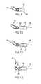
- FIGS. 9-12are views depicting the articulation of the implant of FIG. 1 with respect to installation instruments according to the invention.
- FIGS. 13-16are views showing the placement of an implant of the invention between vertebral bodies using an instrument of the invention.
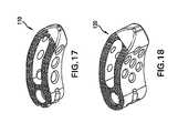
- FIGS. 17-18are side perspective views of alternative embodiments of implants.
- Embodiments of the present inventionare generally directed to implantable spacers that can be used to fuse together a treated area of the spine while restoring or maintaining the proper spacing and natural curvature of the spine.
- the treated areamay include regions between adjacent vertebral bodies so that the height of the spacer corresponds approximately to the height of the disc.
- the height of the spacer ofmay be greater than the height of a disc alone.
- the treated area of the spinemay be prepared by the physician by removing all or part of at least one vertebral body.
- aspects of the inventionallow for more efficient insertion or placement of the spacers into a desired position. Additionally, aspects of the invention also provide suitable rigidity and integrity for supporting the spine during fusion while also providing greater ability to confirm that fusion is taking place as desired.
- spacersmay receive instrumentation for manipulation and insertion of the spacer into its proper position.
- conventional tooling for manipulating the spacergenerally requires that there be greater clearances in the treated area than needed for the spacer alone in order to accommodate the portions of the tooling that extend beyond the surface of the spacer.
- some embodiments of the present inventiondo not require an insertion area that is larger than the spacer.
- the spacerhas one or more tooling engagement surfaces disposed on opposing surfaces of the spacer. The spacer is thereby capable of being manipulated or inserted into position by gripping the engagement surfaces with a suitable tool.
- a suitable gripping toolmay be a device having a plurality of arms that may be selectively expanded or opened and subsequently closed or compressed onto the engagement surface.
- the engagement surfaceis formed from plurality of channels formed in the spacer.
- the spacerOnce the spacer has been moved into position, it is desirable for it to have sufficient structural rigidity or integrity that the spacer does not buckle or otherwise fail under loading by the spine.
- the spacershould be configured so that it meets requirements for axial compression, axial torsion, subsidence, and resistance to expulsion.
- structural rigidity or integrityrefers to the capability of the spacer to resist axial compression and axial torsion without buckling or otherwise failing.
- the spacermeets or exceeds minimum structural rigidity values.
- the rigidity of the spacerexceeds the rigidity of the neighboring vertebral bodies to ensure that the spacer does not collapse or fail under loading conditions first.
- the spaceris capable of bearing axial compression loads of about 10 kN or more, while in another the spacer is capable of undergoing axial compression loading of about 15 kN or more.
- increases in rigidityoften can lead to larger bulk or size of the spacer.
- the spacer 30is capable of bearing axial loads of about 30 kN or less, while in another the spacer is capable of withstanding about 25 kN or less of axial compression. Additionally, these upper and lower limits may be combined in any manner desired. For instance, a spacer of the present invention may be capable of bearing axial compression loads from about 10 kN to about 30 kN, from about 15 kN to about 25 kN, or from about 10 kN to about 25 kN.
- the spacermay be capable of resisting torsional loading at least to the degree of torsional resistance that a healthy disc could provide. In one embodiment, the spacer is capable of resisting about 1.8 Nm or more of torsional loading. In alternate embodiments, however, the spacer is capable of resisting about 40 Nm or more of torsional loading.
- the spacershould be configured so that it subsides in a desired position without substantially sinking into or piercing nearby anatomy when subjected to axial loading.
- Different regions of the spinehave different sized vertebral bodies, each of which may be subjected to different types and amounts of loading.
- vertebral bodies in the lumbar region of the spineare generally larger than vertebral bodies in the cervical region.
- the lumbar region of the spinemay be subjected to approximately 450 N or more of standing trunk weight, whereas the cervical region may only be subjected to about 50 N of head weight.
- the larger size of the vertebral bodies in the lumbar regionhelps distribute the increased loading over a greater area.
- the spaceralso may be configured to resist threshold amounts of expulsion forces.
- a normal discmay be capable of resisting shear stresses up to about 150 N. Therefore, the spacer may be configured to withstand at least the same degree of shear loading without moving out of its desired position. More preferably, however, the spacer is capable of withstanding even greater shear stresses.
- the discmay be capable of withstanding about 600 N or more of shear loading, and in another embodiment it is capable of withstanding about 900 N or more. This feature of the spacer is primarily dependent on the configuration of the protrusions placed on the upper and lower surfaces of the spacer. Thus, the spacer may be configured to withstand even more shear stress, such as loading of about 1000 N or more.
- the height of a spacermay be varied depending upon the height of the area of the spine that is to be treated. For this reason, a plurality of spacers having varying heights may be provided to a physician. This allows the physician to select from a variety of spacer heights during a surgical procedure.
- the height of the windowalso increases as the overall height of each spacer increases, which in turn may change or alter the relationship between the area of the window and the area of the blocked by the material forming the spacer.
- One alternative way to describe the spacer window sizeis by the span or horizontal width of the window.
- Fusiontypically is expected to begin in the anterior region of the treated area.
- One reason for thismay be that the anterior region may undergo more axial loading than the posterior region. The additional pressure in this region may trigger fusion to begin.
- the lines of sight created by the openings or windowsmay be positioned so that they intersect in an anterior region of the treated area.
- any biocompatible materialmay be used to form a spacer of the present invention.
- suitable materials for forming spacers of the present inventionmay be include, but are not limited to, titanium and other surgical grade metals and metal alloys. Since metals and metal alloys generally are radio-opaque, several of the advantages of providing large openings or windows in order to view the treated area will be apparent when the spacer is made of these materials.
- radiolucent materialsalso may be used to form spacers of the present invention. For example, either all or a substantial portion of the spacer may be formed of Polyetheretherketone (PEEK) polymers or similar materials.
- PEEKPolyetheretherketone
- a spacer made of PEEK or other radiolucent materialmay further comprise a pin disposed within the spacer that helps a physician identify the orientation of the spacer during insertion.
- Other materialslikewise may be used to from all or part of the spacers of the present invention.
- all or a portion of the spacermay be formed of bioresorbable materials that, over time, may be resorbed and replaced by bone.
- a spacer or implant 10comprises a support body 12 and a rotatable insert 14 assembly.
- Support body 12may have an arcuate or curved shape extending laterally from a proximal end portion 16 to a distal end portion 18 .
- the distal end 18 portionmay have a tapered end 20 narrowing towards the distal most end.
- a longitudinal opening 22may extend through implant 10 to facilitate bone growth through implant 10 and fusion when implanted.
- a plurality of protrusions or teeth 24may be provided along the superior and inferior end surfaces to facilitate prevention of expulsion of implant 10 from between the adjacent vertebral bodies between which it may be implanted.
- a longitudinal hole 26may be provided to accommodate insert 14 .
- hole 26may be configured and dimensioned to receive insert 14 and permit rotational movement between insert 14 and support body 12 .
- insert 14has a cylindrical shape and allows the implant 10 to turn freely when desired but may be locked, fixed, or stabilized in a predetermined position by insertion tool 28 .
- the positionmay be locked for initial insertion by a sleeve, holder, or stabilization member.
- insert 14may be captured within hole 26 of support body 12 by a circumferential rib 32 on the insert 14 that mates to a corresponding indentation shaped on the support body 12 .
- Insert 14is generally constrained longitudinally with respect to support body 12 .
- Insert 14may have a threaded hole 34 therein extending transverse to longitudinal axis 36 to interface with insertion tool 28 .
- An indention, marking or other alignment mechanism 37may be aligned with hole 34 and may be provided in the superior surface of insert 14 so that a user may visually align the hole 34 with an opening in the proximal end 16 of implant 10 .
- a slot 38may be provided adjacent the threaded hole 34 to provide counter-torque and or stabilization to insert 14 and to facilitate threaded insertion of the insertion instrument 28 with the insert 14 .
- slot 38runs generally perpendicular to threaded hole 34 . As shown in FIGS.
- the proximal end portion 16 of implant 10may have a rounded shape and may include one or more slots or grooves 40 , 46 to engage insertion instrument 28 to facilitate insertion of spacer 10 .
- groove 40extends adjacent the proximal end and extends along the interior curved wall of support body 12 .
- Groove 40has an opening in communication with hole 26 to allow a part of insertion tool 28 to engage threaded hole 34 .
- insertion tool 28may include a shaft 42 with a threaded tip portion 44 to threadedly engage insert 14 .
- another slot 46may be provided adjacent the outer curved wall of support body 12 .
- One or more indentations 48may be provided within groove 46 to accommodate protrusions on insertion tool to enhance gripping of the insertion tool 28 with spacer 10 .
- Openings 50may be provided extending through the curved side walls and into the central longitudinal opening 22 . Openings 50 may facilitate bony ingrowth and may provide a window through which bony fusion may be visually confirmed. As best seen in FIGS. 2-3 , when implant 10 is made from radiolucent material such as PEEK, one or more radio-opaque markers 51 may be integrated into implant 10 such that the implant may be viewed and or located when using fluoroscopy.
- Instrument 28generally comprises an implant stabilizer 62 , an insert stabilizer 64 , and a central shaft 42 extending through the implant and insert stabilizers 62 , 64 .
- central shaft 42has a threaded distal tip portion 44 to threadedly engage insert 14 .
- Insert stabilizer 64may have a generally cylindrical body extending from a proximal end 66 to a distal end 68 . Insert stabilizer 64 is cannulated to accommodate central shaft 42 therethrough.
- distal end 68 of insert stabilizer 64has a forked free end 70 with a pair of tongs or prongs 72 spaced apart and extending distally therefrom.
- the prongs 72are configured and dimensioned to engage slot 38 of insert 14 .
- a keyed slot 74may be provided adjacent the distal end 68 and extending proximally therefrom. Keyed slot 74 is generally configured and dimensioned to engage and interface with a pin 76 provided in implant stabilizer 62 .
- the proximal end 66 of insert stabilizer 64may have an opening 78 extending transversely therethrough configured and dimensioned to receive a rotatable wheel or thumbwheel 80 .
- Thumbwheel 80has a central opening configured to receive central shaft 42 therethrough and a set screw 82 may extend through the thumbwheel 80 to axially and rotationally fix central shaft 42 to thumbwheel 80 so as to rotationally constrain central shaft 42 to thumbwheel 80 .
- a surgeon utilizing the installation instrument 28may rotate the central shaft 42 by rotating the thumbwheel 80 about axis 84 .
- An externally threaded region 86may be provided adjacent opening 78 to interface or otherwise engage an internally threaded stabilizer lock wheel 88 .
- Implant stabilizer 62may be a generally cylindrical cannulated body extending from a proximal end 92 to a distal end 94 configured and dimensioned to extend over insert stabilizer 64 .
- distal end 94 of implant stabilizer 62has a forked free end 96 with a pair of tongs or prongs 98 spaced apart and extending distally therefrom.
- Prongs 98are configured and dimensioned to engage the slots or grooves 40 , 46 of implant 12 .
- a flange or shoulder 100may be provided adjacent proximal end 92 and flange 100 may engage a slot 102 in stabilizer lock wheel 88 to constrain axial movement between the implant stabilizer 62 and stabilizer lock wheel 88 yet allow rotational movement therebetween.
- implant stabilizer 62may be advanced or moved along axis 84 to engage the slots 40 , 46 on implant 10 so as to stabilize implant 10 with respect to prongs 98 .
- prongs 98engaged with slots 40 , 46
- implant 10is rigidly attached to instrument 28 and locked rotationally such that implant 10 is prevented from being rotated or articulated with respect to insertion tool axis 84 .
- the spacermay be hammered or impacted into place between adjacent vertebrae.
- an ergonomic handle 104may be connected to the proximal end 92 of instrument 28 to facilitate handling and/or impaction.
- an alternate T-shaped handle 106may be connected to proximal end 92 of instrument 28 .
- implant stabilizer 62is engaged on implant 10 so as to stabilize implant 10 and/or rigidly attach to instrument 28 .
- implant 10is locked rotationally such that it is prevented from being rotated or articulated with respect to insertion tool axis 84 .
- implant 10may extend in a generally axial direction along axis 84 from the end of tool 28 .
- implant stabilizer 62disengaged from implant 10 , the implant is free to rotate or articulate with respect to axis 84 of insertion tool 28 .
- implant 10may articulate or rotate between about 0 degrees ( FIG. 10 ) and about 90 degrees ( FIG. 12 ).
- the implant 10may be threadedly engaged onto insertion tool 28 using thumbwheel 80 to rotate central shaft 42 and threadedly engage the threaded distal tip portion 44 into threaded hole 34 of insert 14 .
- the stabilizer lock 88may then be turned clockwise to engage implant stabilizer prongs 98 with slots 40 , 46 on implant 10 to prevent implant 10 from rotating about insertion tool axis 84 .
- the insertion tool 28may be impacted from the proximal end. For instance according to one method shown in FIG.
- a surgeonmay impact the proximal end of handle 104 to achieve a desired positioning or depth between adjacent vertebral bodies using, for example, a transforaminal approach.
- the surgeon usermay apply axial force on the insertion tool axis without risk that such impaction will cause the implant to rotate with respect to axis 84 .
- the tapered distal end 20 of implant 10may facilitate distraction separation or spreading apart of the adjacent vertebral bodies.
- a counter lockmay be provided on the installation instrument to prevent stabilizer lock 88 from moving and to prevent implant stabilizer 62 from disengaging from implant 10 during impaction.
- the implant 10may be released from the implant stabilizer 62 by turning the stabilizer lock counterclockwise and retracting stabilizer 62 axially to disengage prongs 98 from slots 40 , 46 .
- the implant stabilizer 62released the implant 10 is free to articulate at the end of insertion tool 28 .
- support body 12may rotate about insert 14 and a central rotation axis 36 extending through the center of insert 14 .
- FIGS. 15-16once the stabilizer 62 is released a surgeon may impact the instrument further to advance the implant 10 into the intervertebral space.
- the outer sidewall of distal end 16 of support body 12is configured and dimensioned to contact or otherwise engage the epiphyseal ring on an anterior portion of a vertebral disc to provide force on the distal end 16 causing implant 10 to rotate in-situ in the intervertebral space about the axis of rotation 36 .
- rotationmay accompany axial translation of axis 36 toward the anterior portion of the disc space, for example, upon impaction of installation instrument 28 .
- implant 10may reach a desired or final installation or implantation position wherein implant 10 is positioned adjacent the epiphyseal ring along the anterior portion of the disc space.
- the insertion instrument 28may be released from implant 10 by unthreading the connection between insertion instrument 28 and insert 14 and insertion instrument 28 may be removed from the body.
- implant 10 and insert 14are configured and dimensioned to remain implanted in the patient.
- implants 110 and 120 according to the inventionare shown.
Landscapes
- Health & Medical Sciences (AREA)
- Engineering & Computer Science (AREA)
- Biomedical Technology (AREA)
- Orthopedic Medicine & Surgery (AREA)
- Life Sciences & Earth Sciences (AREA)
- Neurology (AREA)
- Transplantation (AREA)
- Oral & Maxillofacial Surgery (AREA)
- Heart & Thoracic Surgery (AREA)
- Veterinary Medicine (AREA)
- Public Health (AREA)
- Animal Behavior & Ethology (AREA)
- General Health & Medical Sciences (AREA)
- Cardiology (AREA)
- Vascular Medicine (AREA)
- Surgery (AREA)
- Physical Education & Sports Medicine (AREA)
- Nuclear Medicine, Radiotherapy & Molecular Imaging (AREA)
- Pathology (AREA)
- Medical Informatics (AREA)
- Molecular Biology (AREA)
- Prostheses (AREA)
Abstract
Description
This Patent Application is a continuation application claiming priority to U.S. patent application Ser. No. 13/406,663, filed Feb. 28, 2012, which is a continuation application claiming priority to U.S. patent application Ser. No. 12/250,168 filed on Oct. 13, 2008, now issued as U.S. Pat. No. 8,147,554. Each of these references is hereby incorporated by reference herein in its entirety.
The present invention generally relates to intervertebral spacers for fusing vertebral bodies. In particular, certain embodiments are directed to an intervertebral spacer configured and dimensioned to be implanted transforaminally.
The vertebrate spine is the axis of the skeleton providing structural support for the other body parts. In humans, the normal spine has seven cervical, twelve thoracic and five lumbar segments. The lumbar spine sits upon the sacrum, which then attaches to the pelvis, and in turn is supported by the hip and leg bones. The bony vertebral bodies of the spine are separated by intervertebral discs, which act as joints but allow known degrees of flexion, extension, lateral bending, and axial rotation.
The typical vertebra has a thick anterior bone mass called the vertebral body, with a neural (vertebral) arch that arises from the posterior surface of the vertebral body. The central of adjacent vertebrae are supported by intervertebral discs. Each neural arch combines with the posterior surface of the vertebral body and encloses a vertebral foramen. The vertebral foramina of adjacent vertebrae are aligned to form a vertebral canal, through which the spinal sac, cord and nerve rootlets pass. The portion of the neural arch which extends posteriorly and acts to protect the spinal cord's posterior side is known as the lamina. Projecting from the posterior region of the neural arch is the spinous process.
The intervertebral disc primarily serves as a mechanical cushion permitting controlled motion between vertebral segments of the axial skeleton. The normal disc is a unique, mixed structure, comprised of three component tissues: the nucleus pulpous (“nucleus”), the annulus fibrosus (“annulus”) and two vertebral end plates. The two vertebral end plates are composed of thin cartilage overlying a thin layer of hard, cortical bone which attaches to the spongy, richly vascular, cancellous bone of the vertebral body. The end plates thus act to attach adjacent vertebrae to the disc. In other words, a transitional zone is created by the end plates between the malleable disc and the bony vertebrae.
The spinal disc and/or vertebral bodies may be displaced or damaged due to trauma, disease, degenerative defects, or wear over an extended period of time. One result of this displacement or damage to a spinal disc or vertebral body may be chronic back pain.
A disc herniation occurs when the annulus fibers are weakened or torn and the inner tissue of the nucleus becomes permanently bulged, distended, or extruded out of its normal, internal annulus confines. The mass of a herniated or “slipped” nucleus tissue can compress a spinal nerve, resulting in leg pain, loss of muscle control, or even paralysis. Alternatively, with discal degeneration, the nucleus loses its water binding ability and deflates, as though the air had been let out of a tire. Subsequently, the height of the nucleus decreases causing the annulus to buckle in areas where the laminated plies are loosely bonded. As these overlapping laminated plies of the annulus begin to buckle and separate, either circumferential or radial annular tears may occur, which may contribute to persistent or disabling back pain. Adjacent, ancillary spinal facet joints will also be forced into an overriding position, which may create additional back pain.
Whenever the nucleus tissue is herniated or removed by surgery, the disc space will narrow and may lose much of its normal stability. In many cases, to alleviate back pain from degenerated or herniated discs, the disc is removed along with all or part of at least one neighboring vertebrae and is replaced by an implant that promotes fusion of the remaining bony anatomy.
While this treatment may help alleviate the pain once the vertebrae have been successfully fused together, there remains the possibility that the surgical procedure may not successfully or fully bring about the intended fusion. The success or failure of spinal fusion may depend upon several factors. For instance, the spacer—or implant or cage—used to fill the space left by the removed disc and bony anatomy must be sufficiently strong to support the spine under a wide range of loading conditions. The spacer should also be configured so that it is likely to remain in place once it has been positioned in the spine by the surgeon. Additionally, the material used for the spacer should be a biocompatible material and should have a configuration that promotes bony ingrowth.
As a result, the design of the implant should provide sufficient rigidity and strength to resist deformation when loading forces are applied to it. Likewise, the implant should sufficiently resist sliding or movement of the implant as a result of torsional or shearing loads. Often, these parameters lead designers to select predominantly solid structures made of bone or of radio opaque materials such as titanium.
Instrumentation and specialized tools for insertion of an intervertebral implant is yet another design parameter to consider when designing a spacer. Spinal fusion procedures can present several challenges because of the small clearances around the spacer when it is being inserted into position. For instance, the instrumentation used may securely grip the implant on opposing sides or surfaces. For example, the superior and inferior surfaces may have one or more regions in which no gripping teeth are present. Such protrusion-free zones enable the implant to be grasped and manipulated by elongate rectangular blades. Notably, these protrusion-free zones are not formed as channels cut into the surface of the implant in order to maintain the strength and integrity of the implant so that it is less prone to failure. Thus, the clearance required in order to insert the spacer must be higher than the spacer itself in order to accommodate the instrumentation. For this reason, distraction of the treated area typically is greater than the implant itself.
Similarly, when the gripping tools used to manipulate and insert the implant are on the sides of the spacer, additional clearance typically is needed in order to accommodate the added width of the insertion tool blades. Such increases in height or width of the profile of the spacer when coupled or in communication with instrumentation means that additional space is needed in order to insert the spacer. In some circumstances, providing for this additional clearance space can be difficult to achieve.
Thus, despite known devices that promote fusion of a treated area of the spine, there remains a need for spacer designs that optimize bony ingrowth, have structural rigidity to support the spine under a variety of loading conditions, and allow for insertion through a smaller profile.
Embodiments of the present invention are generally directed to implantable spacers that can be used to fuse together a treated area of the spine while restoring or maintaining the proper spacing and natural curvature of the spine. The treated area may include regions between adjacent vertebral bodies so that the height of the spacer corresponds approximately to the height of the disc. In some embodiments, the height of the spacer of may be greater than the height of a disc alone. For instance, the treated area of the spine may be prepared by the physician by removing all or part of at least one vertebral body.
As explained in greater detail below, several features of the invention allow for more efficient insertion or placement of the spacers into a desired position. Additionally, aspects of the invention also provide suitable rigidity and integrity for supporting the spine during fusion while also providing greater ability to confirm that fusion is taking place as desired.
One feature that may result in more efficient insertion or placement of embodiments of spacers according to the invention concerns how the spacers may receive instrumentation for manipulation and insertion of the spacer into its proper position. As mentioned above, conventional tooling for manipulating the spacer generally requires that there be greater clearances in the treated area than needed for the spacer alone in order to accommodate the portions of the tooling that extend beyond the surface of the spacer. In contrast, some embodiments of the present invention do not require an insertion area that is larger than the spacer. Thus, in one embodiment the spacer has one or more tooling engagement surfaces disposed on opposing surfaces of the spacer. The spacer is thereby capable of being manipulated or inserted into position by gripping the engagement surfaces with a suitable tool.
For instance, one example of a suitable gripping tool may be a device having a plurality of arms that may be selectively expanded or opened and subsequently closed or compressed onto the engagement surface. In one embodiment, the engagement surface is formed from plurality of channels formed in the spacer. In one variation, there is a channel located at each engagement surface in which the arms of the manipulating or insertion tool may be disposed to further help ensure that the tooling does not project beyond the largest cross-sectional view of the spacer when viewed along the direction in which the spacer will travel during insertion.
Once the spacer has been moved into position, it is desirable for it to have sufficient structural rigidity or integrity that the spacer does not buckle or otherwise fail under loading by the spine. In general, the spacer should be configured so that it meets requirements for axial compression, axial torsion, subsidence, and resistance to expulsion. As used herein, structural rigidity or integrity refers to the capability of the spacer to resist axial compression and axial torsion without buckling or otherwise failing.
In order to minimize the risk of failure from compressive or torsional loading, it is preferred that the spacer meets or exceeds minimum structural rigidity values. In general, it is preferred that the rigidity of the spacer exceeds the rigidity of the neighboring vertebral bodies to ensure that the spacer does not collapse or fail under loading conditions first. For instance, in one embodiment the spacer is capable of bearing axial compression loads of about 10 kN or more, while in another the spacer is capable of undergoing axial compression loading of about 15 kN or more. In general, increases in rigidity often can lead to larger bulk or size of the spacer. Thus, while the spacer should be sufficiently rigid to withstand expected loading conditions, eventually the benefits of increasing rigidity become outweighed by other disadvantages such as overall size of the spacer or its ability to provide through holes for promoting fusion. For example, in one embodiment, the spacer30 is capable of bearing axial loads of about 30 kN or less, while in another the spacer is capable of withstanding about 25 kN or less of axial compression. Additionally, these upper and lower limits may be combined in any manner desired. For instance, a spacer of the present invention may be capable of bearing axial compression loads from about 10 kN to about 30 kN, from about 15 kN to about 25 kN, or from about 10 kN to about 25 kN.
Likewise, the spacer may be capable of resisting torsional loading at least to the degree of torsional resistance that a healthy disc could provide. In one embodiment, the spacer is capable of resisting about 1.8 Nm or more of torsional loading. In alternate embodiments, however, the spacer is capable of resisting about 40 Nm or more of torsional loading.
In addition to having structural rigidity or integrity, the spacer should be configured so that it subsides in a desired position without substantially sinking into or piercing nearby anatomy when subjected to axial loading. Different regions of the spine have different sized vertebral bodies, each of which may be subjected to different types and amounts of loading. For instance, vertebral bodies in the lumbar region of the spine are generally larger than vertebral bodies in the cervical region. Typically, the lumbar region of the spine may be subjected to approximately 450 N or more of standing trunk weight, whereas the cervical region may only be subjected to about 50 N of head weight. The larger size of the vertebral bodies in the lumbar region helps distribute the increased loading over a greater area.
The spacer also may be configured to resist threshold amounts of expulsion forces. For example, a normal disc may be capable of resisting shear stresses up to about 150 N. Therefore, the spacer may be configured to withstand at least the same degree of shear loading without moving out of its desired position. More preferably, however, the spacer is capable of withstanding even greater shear stresses. For example, the disc may be capable of withstanding about 600 N or more of shear loading, and in another embodiment it is capable of withstanding about 900 N or more. This feature of the spacer is primarily dependent on the configuration of the protrusions placed on the upper and lower surfaces of the spacer. Thus, the spacer may be configured to withstand even more shear stress, such as loading of about 1000 N or more.
The height of a spacer may be varied depending upon the height of the area of the spine that is to be treated. For this reason, a plurality of spacers having varying heights may be provided to a physician. This allows the physician to select from a variety of spacer heights during a surgical procedure. In one embodiment, the height of the window also increases as the overall height of each spacer increases, which in turn may change or alter the relationship between the area of the window and the area of the blocked by the material forming the spacer. One alternative way to describe the spacer window size is by the span or horizontal width of the window.
Fusion typically is expected to begin in the anterior region of the treated area. One reason for this may be that the anterior region may undergo more axial loading than the posterior region. The additional pressure in this region may trigger fusion to begin. Thus, the lines of sight created by the openings or windows may be positioned so that they intersect in an anterior region of the treated area.
Any biocompatible material may be used to form a spacer of the present invention. For example, suitable materials for forming spacers of the present invention may be include, but are not limited to, titanium and other surgical grade metals and metal alloys. Since metals and metal alloys generally are radio-opaque, several of the advantages of providing large openings or windows in order to view the treated area will be apparent when the spacer is made of these materials. In addition, radiolucent materials also may be used to form spacers of the present invention. For example, either all or a substantial portion of the spacer may be formed of Polyetheretherketone (PEEK) polymers or similar materials. A spacer made of PEEK or other radiolucent material may further comprise a pin disposed within the spacer that helps a physician identify the orientation of the spacer during insertion. Other materials likewise may be used to from all or part of the spacers of the present invention. For example, all or a portion of the spacer may be formed of bioresorbable materials that, over time, may be resorbed and replaced by bone.
These and other features are explained more fully in the embodiments illustrated below. It should be understood that in general the features of one embodiment also may be used in combination with features of another embodiment and that the embodiments are not intended to limit the scope of the invention.
Referring toFIGS. 1-5 , one embodiment of a spacer orimplant 10 according to the invention comprises asupport body 12 and arotatable insert 14 assembly.Support body 12 may have an arcuate or curved shape extending laterally from aproximal end portion 16 to adistal end portion 18. Thedistal end 18 portion may have a taperedend 20 narrowing towards the distal most end. In one embodiment, alongitudinal opening 22 may extend throughimplant 10 to facilitate bone growth throughimplant 10 and fusion when implanted. A plurality of protrusions orteeth 24 may be provided along the superior and inferior end surfaces to facilitate prevention of expulsion ofimplant 10 from between the adjacent vertebral bodies between which it may be implanted.
In one variation alongitudinal hole 26 may be provided to accommodateinsert 14. In this regard,hole 26 may be configured and dimensioned to receiveinsert 14 and permit rotational movement betweeninsert 14 andsupport body 12. In one variation, insert14 has a cylindrical shape and allows theimplant 10 to turn freely when desired but may be locked, fixed, or stabilized in a predetermined position byinsertion tool 28. For example, the position may be locked for initial insertion by a sleeve, holder, or stabilization member. According to one embodiment, insert14 may be captured withinhole 26 ofsupport body 12 by acircumferential rib 32 on theinsert 14 that mates to a corresponding indentation shaped on thesupport body 12. In this regard, once assembled, insert14 is generally constrained longitudinally with respect to supportbody 12.Insert 14 may have a threadedhole 34 therein extending transverse tolongitudinal axis 36 to interface withinsertion tool 28. An indention, marking orother alignment mechanism 37 may be aligned withhole 34 and may be provided in the superior surface ofinsert 14 so that a user may visually align thehole 34 with an opening in theproximal end 16 ofimplant 10. Aslot 38 may be provided adjacent the threadedhole 34 to provide counter-torque and or stabilization to insert14 and to facilitate threaded insertion of theinsertion instrument 28 with theinsert 14. In one variation, slot38 runs generally perpendicular to threadedhole 34. As shown inFIGS. 1, 4A -D, and5B, theproximal end portion 16 ofimplant 10 may have a rounded shape and may include one or more slots orgrooves insertion instrument 28 to facilitate insertion ofspacer 10. In one embodiment,groove 40 extends adjacent the proximal end and extends along the interior curved wall ofsupport body 12.Groove 40 has an opening in communication withhole 26 to allow a part ofinsertion tool 28 to engage threadedhole 34. For example, in onevariation insertion tool 28 may include ashaft 42 with a threadedtip portion 44 to threadedly engageinsert 14. As shown inFIG. 4B anotherslot 46 may be provided adjacent the outer curved wall ofsupport body 12. One ormore indentations 48 may be provided withingroove 46 to accommodate protrusions on insertion tool to enhance gripping of theinsertion tool 28 withspacer 10.
One ormore openings 50 may be provided extending through the curved side walls and into the centrallongitudinal opening 22.Openings 50 may facilitate bony ingrowth and may provide a window through which bony fusion may be visually confirmed. As best seen inFIGS. 2-3 , whenimplant 10 is made from radiolucent material such as PEEK, one or more radio-opaque markers 51 may be integrated intoimplant 10 such that the implant may be viewed and or located when using fluoroscopy.
Referring toFIG. 6 , an exploded view of one embodiment of aninsertion instrument 28 according to the invention is shown.Instrument 28 generally comprises animplant stabilizer 62, aninsert stabilizer 64, and acentral shaft 42 extending through the implant and insertstabilizers central shaft 42 has a threadeddistal tip portion 44 to threadedly engageinsert 14.Insert stabilizer 64 may have a generally cylindrical body extending from a proximal end66 to adistal end 68.Insert stabilizer 64 is cannulated to accommodatecentral shaft 42 therethrough. In one variation,distal end 68 ofinsert stabilizer 64 has a forkedfree end 70 with a pair of tongs orprongs 72 spaced apart and extending distally therefrom. Theprongs 72 are configured and dimensioned to engageslot 38 ofinsert 14. Akeyed slot 74 may be provided adjacent thedistal end 68 and extending proximally therefrom.Keyed slot 74 is generally configured and dimensioned to engage and interface with apin 76 provided inimplant stabilizer 62. The proximal end66 ofinsert stabilizer 64 may have anopening 78 extending transversely therethrough configured and dimensioned to receive a rotatable wheel orthumbwheel 80.Thumbwheel 80 has a central opening configured to receivecentral shaft 42 therethrough and aset screw 82 may extend through thethumbwheel 80 to axially and rotationally fixcentral shaft 42 to thumbwheel80 so as to rotationally constraincentral shaft 42 tothumbwheel 80. In this regard, in operation a surgeon utilizing theinstallation instrument 28 may rotate thecentral shaft 42 by rotating thethumbwheel 80 aboutaxis 84. An externally threadedregion 86 may be providedadjacent opening 78 to interface or otherwise engage an internally threadedstabilizer lock wheel 88.
Referring now toFIGS. 9-12 , the articulatability ofimplant 10 with respect toinstallation instrument 28 is shown. As shown inFIG. 9 ,implant stabilizer 62 is engaged onimplant 10 so as to stabilizeimplant 10 and/or rigidly attach toinstrument 28. In this position,implant 10 is locked rotationally such that it is prevented from being rotated or articulated with respect toinsertion tool axis 84. In one variation, shown inFIG. 9 ,implant 10 may extend in a generally axial direction alongaxis 84 from the end oftool 28. Referring toFIGS. 10-12 , withimplant stabilizer 62 disengaged fromimplant 10, the implant is free to rotate or articulate with respect toaxis 84 ofinsertion tool 28. In one variation,implant 10 may articulate or rotate between about 0 degrees (FIG. 10 ) and about 90 degrees (FIG. 12 ).
Referring now toFIGS. 13-16 , one embodiment of a method of usingimplant 10 in conjunction withinserter 28 is shown. In a first step, theimplant 10 may be threadedly engaged ontoinsertion tool 28 usingthumbwheel 80 to rotatecentral shaft 42 and threadedly engage the threadeddistal tip portion 44 into threadedhole 34 ofinsert 14. Thestabilizer lock 88 may then be turned clockwise to engage implant stabilizer prongs98 withslots implant 10 to preventimplant 10 from rotating aboutinsertion tool axis 84. In this position, with theimplant 10 fixed or stabilized with respect to theinsertion instrument 28, theinsertion tool 28 may be impacted from the proximal end. For instance according to one method shown inFIG. 13 , a surgeon may impact the proximal end ofhandle 104 to achieve a desired positioning or depth between adjacent vertebral bodies using, for example, a transforaminal approach. As explained above, the surgeon user may apply axial force on the insertion tool axis without risk that such impaction will cause the implant to rotate with respect toaxis 84. The tapereddistal end 20 ofimplant 10 may facilitate distraction separation or spreading apart of the adjacent vertebral bodies. A counter lock may be provided on the installation instrument to preventstabilizer lock 88 from moving and to preventimplant stabilizer 62 from disengaging fromimplant 10 during impaction.
Referring toFIG. 14 , once impacted to a desired position, theimplant 10 may be released from theimplant stabilizer 62 by turning the stabilizer lock counterclockwise and retractingstabilizer 62 axially to disengageprongs 98 fromslots implant stabilizer 62 released theimplant 10 is free to articulate at the end ofinsertion tool 28. In this regard, in thisposition support body 12 may rotate aboutinsert 14 and acentral rotation axis 36 extending through the center ofinsert 14. Referring toFIGS. 15-16 , once thestabilizer 62 is released a surgeon may impact the instrument further to advance theimplant 10 into the intervertebral space. In this regard, the outer sidewall ofdistal end 16 ofsupport body 12 is configured and dimensioned to contact or otherwise engage the epiphyseal ring on an anterior portion of a vertebral disc to provide force on thedistal end 16 causingimplant 10 to rotate in-situ in the intervertebral space about the axis ofrotation 36. In certain methods, such rotation may accompany axial translation ofaxis 36 toward the anterior portion of the disc space, for example, upon impaction ofinstallation instrument 28. Referring toFIG. 16 , according to one method,implant 10 may reach a desired or final installation or implantation position whereinimplant 10 is positioned adjacent the epiphyseal ring along the anterior portion of the disc space. Once the desired or final installation position ofimplant 10 is reached, theinsertion instrument 28 may be released fromimplant 10 by unthreading the connection betweeninsertion instrument 28 and insert14 andinsertion instrument 28 may be removed from the body. In this regard,implant 10 and insert14 are configured and dimensioned to remain implanted in the patient.
Referring toFIGS. 17-18 , alternative embodiments ofimplants
While it is apparent that the invention disclosed herein is well calculated to fulfill the objects stated above, it will be appreciated that numerous modifications and embodiments may be devised by those skilled in the art.
Claims (20)
1. A surgical method comprising:
attaching an implant to an insertion instrument, wherein the insertion instrument has a first configuration relative to the implant such that the implant is rotatably fixed to the insertion instrument, wherein in the first configuration in which the implant is rotatably fixed a pair of tongs from the insertion instrument engage a portion of an outer perimeter of the implant;
inserting the implant into a disc space via a transforaminal approach;
impacting the insertion instrument to advance the implant to a desired position within the disc space;
moving the insertion instrument from the first configuration to a second configuration relative to the implant wherein the implant is rotatable relative to the insertion instrument; and
rotating the implant within the disc space via impaction of the insertion instrument, wherein impaction causes the implant to rotate via engagement of the implant with a vertebral ring within the disc space,
wherein the implant comprises a proximal end portion, a distal end portion, a first curved lateral wall extending from the proximal end portion to the distal end portion, and a second curved lateral wall extending from the proximal end portion to the distal end portion,
wherein the implant includes a superior surface and an inferior surface, wherein at least one of the superior surface and inferior surface include a plurality of protrusions,
wherein the implant includes an engagement surface between the superior surface and the inferior surface, wherein the insertion instrument is engageable with the engagement surface,
wherein the insertion instrument grips the proximal end portion of the implant; and
wherein a proximal most end of the proximal end portion of the implant comprises a smooth rounded surface.
2. The surgical method ofclaim 1 , wherein the implant is rotatable relative to the insertion instrument between 0 and 90 degrees.
3. The surgical method ofclaim 1 , wherein the implant is rotatable relative to the insertion instrument up to 80 degrees.
4. The surgical method ofclaim 1 , wherein the implant further comprises a central longitudinal opening.
5. The surgical method ofclaim 1 , wherein the first curved lateral wall of the implant is convexly curved and the second curved lateral wall of the implant is concavely curved.
6. The surgical method ofclaim 5 , wherein the implant further includes at least one radiopaque marker, wherein the radiopaque marker is positioned closer to the convexly curved lateral wall than the concavely curved lateral wall.
7. The surgical method ofclaim 6 , wherein the at least one radiopaque marker is positioned in a channel that extends from at least one of the superior surface or the inferior surface of the implant.
8. The surgical method ofclaim 6 , wherein the channel that receives the radiopaque marker is formed through the plurality of protrusions that extend from the at least one of the superior surface or the inferior surface of the implant.
9. The surgical method ofclaim 1 , wherein the implant further comprises a central longitudinal opening and one or more openings formed on at least one of the first curved lateral wall and the second curved lateral wall, wherein the one or more openings are in communication with the central longitudinal opening.
10. The surgical method ofclaim 9 , wherein the implant comprises exactly one opening in communication within the central longitudinal opening formed in either the first curved lateral wall or the second curved lateral wall.
11. A surgical method comprising:
attaching an implant to an insertion instrument, wherein the insertion instrument has a first configuration relative to the implant such that the implant is rotatably fixed to the insertion instrument, wherein in the first configuration in which the implant is rotatably fixed a pair of tongs from the insertion instrument engage a portion of an outer perimeter of the implant;
inserting the implant into a disc space via a transforaminal approach;
moving the insertion instrument from the first configuration to a second configuration relative to the implant wherein the implant is rotatable relative to the insertion instrument; and
rotating the implant within the disc space via impaction of the insertion instrument, wherein impaction causes the implant to rotate via engagement of the implant with a vertebral ring within the disc space,
wherein the implant comprises a proximal end portion, a distal end portion, a first curved lateral wall extending from the proximal end portion to the distal end portion, and a second curved lateral wall extending from the proximal end portion to the distal end portion,
wherein the implant includes a superior surface and an inferior surface, wherein at least one of the superior surface and inferior surface include a plurality of protrusions,
wherein the implant includes an engagement surface between the superior surface and the inferior surface,
wherein the insertion instrument is engageable with the proximal end portion via the engagement surface,
wherein a proximal most end of the proximal end portion comprises a smooth rounded surface,
wherein the implant includes a central longitudinal opening, and
wherein the implant includes a radiopaque marker positioned in a channel formed between the central longitudinal opening and one of the first curved lateral wall and the second curved lateral wall.
12. The surgical method ofclaim 11 , wherein the proximal end portion of the implant comprises at least one groove for receiving the insertion instrument therein.
13. The surgical method ofclaim 12 , wherein the insertion instrument is configured to engage an engagement surface that is positioned between the superior surface and the inferior surface of the implant.
14. The surgical method ofclaim 11 , wherein the at least one of the superior surface and inferior surface is only partially covered with the plurality of protrusions.
15. The surgical method ofclaim 11 , wherein the channel for receiving the radiopaque marker is formed through the plurality of protrusions.
16. The surgical method ofclaim 11 , wherein in the second configuration, the implant is rotatable up to 80 degrees relative to the insertion instrument.
17. The surgical method ofclaim 11 , wherein the first curved lateral wall is a convex anterior wall and the second curved lateral wall is a concave posterior wall, wherein the radiopaque marker is positioned closer to the convex anterior wall than the concave posterior wall.
18. The surgical method ofclaim 11 , wherein the implant further includes one or more openings formed on at least one of the first curved lateral wall and the second curved lateral wall, wherein the one or more openings are in communication with the central longitudinal opening.
19. The surgical method ofclaim 11 , wherein the proximal end portion of the implant is round and the distal end portion of the implant is tapered.
20. The surgical method ofclaim 11 , wherein the central longitudinal opening comprises a first convex end, a second convex end, a first inner curved lateral wall and a second inner curved lateral wall, wherein the first convex end extends from the first inner curved lateral wall to the second inner curved lateral wall and the second convex end extends from the first inner curved lateral wall to the second inner curved lateral wall.
Priority Applications (4)
| Application Number | Priority Date | Filing Date | Title |
|---|---|---|---|
| US14/683,502US9782269B2 (en) | 2008-10-13 | 2015-04-10 | Intervertebral spacer |
| US15/695,593US10130490B2 (en) | 2008-10-13 | 2017-09-05 | Intervertebral spacer |
| US16/159,926US11026803B2 (en) | 2008-10-13 | 2018-10-15 | Intervertebral spacer |
| US17/340,406US11896497B2 (en) | 2008-10-13 | 2021-06-07 | Intervertebral spacer |
Applications Claiming Priority (3)
| Application Number | Priority Date | Filing Date | Title |
|---|---|---|---|
| US12/250,168US8147554B2 (en) | 2008-10-13 | 2008-10-13 | Intervertebral spacer |
| US13/406,663US9138330B2 (en) | 2008-10-13 | 2012-02-28 | Intervertebral spacer |
| US14/683,502US9782269B2 (en) | 2008-10-13 | 2015-04-10 | Intervertebral spacer |
Related Parent Applications (1)
| Application Number | Title | Priority Date | Filing Date |
|---|---|---|---|
| US13/406,663ContinuationUS9138330B2 (en) | 2008-10-13 | 2012-02-28 | Intervertebral spacer |
Related Child Applications (1)
| Application Number | Title | Priority Date | Filing Date |
|---|---|---|---|
| US15/695,593ContinuationUS10130490B2 (en) | 2008-10-13 | 2017-09-05 | Intervertebral spacer |
Publications (2)
| Publication Number | Publication Date |
|---|---|
| US20150209155A1 US20150209155A1 (en) | 2015-07-30 |
| US9782269B2true US9782269B2 (en) | 2017-10-10 |
Family
ID=42099616
Family Applications (6)
| Application Number | Title | Priority Date | Filing Date |
|---|---|---|---|
| US12/250,168Active2030-02-15US8147554B2 (en) | 2008-10-13 | 2008-10-13 | Intervertebral spacer |
| US13/406,663ActiveUS9138330B2 (en) | 2008-10-13 | 2012-02-28 | Intervertebral spacer |
| US14/683,502ActiveUS9782269B2 (en) | 2008-10-13 | 2015-04-10 | Intervertebral spacer |
| US15/695,593ActiveUS10130490B2 (en) | 2008-10-13 | 2017-09-05 | Intervertebral spacer |
| US16/159,926Active2029-02-17US11026803B2 (en) | 2008-10-13 | 2018-10-15 | Intervertebral spacer |
| US17/340,406Active2029-12-08US11896497B2 (en) | 2008-10-13 | 2021-06-07 | Intervertebral spacer |
Family Applications Before (2)
| Application Number | Title | Priority Date | Filing Date |
|---|---|---|---|
| US12/250,168Active2030-02-15US8147554B2 (en) | 2008-10-13 | 2008-10-13 | Intervertebral spacer |
| US13/406,663ActiveUS9138330B2 (en) | 2008-10-13 | 2012-02-28 | Intervertebral spacer |
Family Applications After (3)
| Application Number | Title | Priority Date | Filing Date |
|---|---|---|---|
| US15/695,593ActiveUS10130490B2 (en) | 2008-10-13 | 2017-09-05 | Intervertebral spacer |
| US16/159,926Active2029-02-17US11026803B2 (en) | 2008-10-13 | 2018-10-15 | Intervertebral spacer |
| US17/340,406Active2029-12-08US11896497B2 (en) | 2008-10-13 | 2021-06-07 | Intervertebral spacer |
Country Status (4)
| Country | Link |
|---|---|
| US (6) | US8147554B2 (en) |
| EP (1) | EP2364114B1 (en) |
| JP (1) | JP5452605B2 (en) |
| WO (1) | WO2010045231A1 (en) |
Cited By (6)
| Publication number | Priority date | Publication date | Assignee | Title |
|---|---|---|---|---|
| US20170360574A1 (en)* | 2008-10-13 | 2017-12-21 | Globus Medical, Inc. | Intervertebral spacer |
| US11039931B2 (en) | 2019-02-01 | 2021-06-22 | Globus Medical, Inc. | Intervertebral spinal implant |
| US11364057B2 (en) | 2009-03-27 | 2022-06-21 | Spinal Elements, Inc. | Flanged interbody fusion device |
| US11382769B2 (en) | 2018-09-20 | 2022-07-12 | Spinal Elements, Inc. | Spinal implant device |
| US11911284B2 (en) | 2020-11-19 | 2024-02-27 | Spinal Elements, Inc. | Curved expandable interbody devices and deployment tools |
| US12279969B2 (en) | 2020-12-17 | 2025-04-22 | Spinal Elements, Inc. | Spinal implant device |
Families Citing this family (221)
| Publication number | Priority date | Publication date | Assignee | Title |
|---|---|---|---|---|
| US8236029B2 (en) | 2004-08-11 | 2012-08-07 | Nlt Spine Ltd. | Devices for introduction into a body via a substantially straight conduit to for a predefined curved configuration, and methods employing such devices |
| WO2006058221A2 (en) | 2004-11-24 | 2006-06-01 | Abdou Samy M | Devices and methods for inter-vertebral orthopedic device placement |
| US7959675B2 (en)* | 2005-04-08 | 2011-06-14 | G&L Consulting, Llc | Spine implant insertion device and method |
| US8500778B2 (en)* | 2006-02-01 | 2013-08-06 | DePuy Synthes Products, LLC | Interspinous process spacer |
| US8409290B2 (en)* | 2006-03-08 | 2013-04-02 | Seaspine, Inc. | Interbody device for spinal applications |
| US8641764B2 (en)* | 2006-10-11 | 2014-02-04 | G&L Consulting, Llc | Spine implant insertion device and method |
| WO2008070863A2 (en) | 2006-12-07 | 2008-06-12 | Interventional Spine, Inc. | Intervertebral implant |
| US20080140085A1 (en)* | 2006-12-11 | 2008-06-12 | G&L Consulting, Llc | Steerable spine implant insertion device and method |
| US9039768B2 (en) | 2006-12-22 | 2015-05-26 | Medos International Sarl | Composite vertebral spacers and instrument |
| EP2237748B1 (en) | 2008-01-17 | 2012-09-05 | Synthes GmbH | An expandable intervertebral implant |
| US20090248092A1 (en) | 2008-03-26 | 2009-10-01 | Jonathan Bellas | Posterior Intervertebral Disc Inserter and Expansion Techniques |
| US8216317B2 (en) | 2008-03-31 | 2012-07-10 | Stryker Spine | Spinal implant apparatus and methods |
| US8936641B2 (en) | 2008-04-05 | 2015-01-20 | DePuy Synthes Products, LLC | Expandable intervertebral implant |
| US8545566B2 (en)* | 2008-10-13 | 2013-10-01 | Globus Medical, Inc. | Articulating spacer |
| AU2009329873A1 (en)* | 2008-12-26 | 2011-11-03 | Scott Spann | Minimally-invasive retroperitoneal lateral approach for spinal surgery |
| US9526620B2 (en) | 2009-03-30 | 2016-12-27 | DePuy Synthes Products, Inc. | Zero profile spinal fusion cage |
| US8252060B2 (en)* | 2009-04-02 | 2012-08-28 | Globus Medical Inc. | Method of installation of intervertebral spacers |
| US8241364B2 (en)* | 2009-04-02 | 2012-08-14 | Globus Medical, Inc. | Method of installation of intervertebral spacers |
| US8998924B2 (en) | 2009-04-16 | 2015-04-07 | Coalign Innovations, Inc. | Insertion handle for surgical implants |
| FR2944692B1 (en)* | 2009-04-27 | 2011-04-15 | Medicrea International | MATERIAL OF VERTEBRAL OSTEOSYNTHESIS |
| US9642722B2 (en) | 2009-07-02 | 2017-05-09 | Atlas Spine, Inc. | Intervertebral expandable spacer |
| US10098758B2 (en) | 2009-10-15 | 2018-10-16 | Globus Medical, Inc. | Expandable fusion device and method of installation thereof |
| US11103366B2 (en) | 2009-10-15 | 2021-08-31 | Globus Medical, Inc. | Expandable fusion device and method of installation thereof |
| US10327917B2 (en) | 2009-10-15 | 2019-06-25 | Globus Medical, Inc. | Expandable fusion device and method of installation thereof |
| US8709086B2 (en) | 2009-10-15 | 2014-04-29 | Globus Medical, Inc. | Expandable fusion device and method of installation thereof |
| US11564807B2 (en) | 2009-10-15 | 2023-01-31 | Globus Medical, Inc. | Expandable fusion device and method of installation thereof |
| US10806596B2 (en) | 2009-10-15 | 2020-10-20 | Globus Medical, Inc. | Expandable fusion device and method installation thereof |
| US8685098B2 (en) | 2010-06-25 | 2014-04-01 | Globus Medical, Inc. | Expandable fusion device and method of installation thereof |
| US9155628B2 (en) | 2009-10-15 | 2015-10-13 | Globus Medical, Inc. | Expandable fusion device and method of installation thereof |
| US8062375B2 (en) | 2009-10-15 | 2011-11-22 | Globus Medical, Inc. | Expandable fusion device and method of installation thereof |
| US9216095B2 (en) | 2009-10-15 | 2015-12-22 | Globus Medical, Inc. | Expandable fusion device and method of installation thereof |
| US8556979B2 (en) | 2009-10-15 | 2013-10-15 | Globus Medical, Inc. | Expandable fusion device and method of installation thereof |
| US11344430B2 (en) | 2009-10-15 | 2022-05-31 | Globus Medical, Inc. | Expandable fusion device and method of installation thereof |
| US9028553B2 (en) | 2009-11-05 | 2015-05-12 | DePuy Synthes Products, Inc. | Self-pivoting spinal implant and associated instrumentation |
| US8764806B2 (en) | 2009-12-07 | 2014-07-01 | Samy Abdou | Devices and methods for minimally invasive spinal stabilization and instrumentation |
| US9393129B2 (en) | 2009-12-10 | 2016-07-19 | DePuy Synthes Products, Inc. | Bellows-like expandable interbody fusion cage |
| PL217567B1 (en)* | 2010-03-03 | 2014-07-31 | Lfc Spółka Z Ograniczoną Odpowiedzialnością | Prosthesis of anterior spinal column, prosthesis guiding tool and method for the implantation thereof |
| US8870880B2 (en) | 2010-04-12 | 2014-10-28 | Globus Medical, Inc. | Angling inserter tool for expandable vertebral implant |
| US9907560B2 (en) | 2010-06-24 | 2018-03-06 | DePuy Synthes Products, Inc. | Flexible vertebral body shavers |
| US8979860B2 (en) | 2010-06-24 | 2015-03-17 | DePuy Synthes Products. LLC | Enhanced cage insertion device |
| US9597200B2 (en) | 2010-06-25 | 2017-03-21 | Globus Medical, Inc | Expandable fusion device and method of installation thereof |
| US8623091B2 (en) | 2010-06-29 | 2014-01-07 | DePuy Synthes Products, LLC | Distractible intervertebral implant |
| US10945858B2 (en) | 2010-09-03 | 2021-03-16 | Globus Medical, Inc. | Expandable interspinous process fixation device |
| US10512550B2 (en) | 2010-09-03 | 2019-12-24 | Globus Medical, Inc. | Expandable interspinous process fixation device |
| US9474625B2 (en) | 2010-09-03 | 2016-10-25 | Globus Medical, Inc | Expandable fusion device and method of installation thereof |
| US9855151B2 (en) | 2010-09-03 | 2018-01-02 | Globus Medical, Inc | Expandable fusion device and method of installation thereof |
| US12059358B2 (en) | 2010-09-03 | 2024-08-13 | Globus Medical Inc. | Expandable fusion device and method of installation thereof |
| US10779957B2 (en) | 2010-09-03 | 2020-09-22 | Globus Medical, Inc. | Expandable fusion device and method of installation thereof |
| US9566168B2 (en) | 2010-09-03 | 2017-02-14 | Globus Medical, Inc. | Expandable fusion device and method of installation thereof |
| US9907673B2 (en) | 2010-09-03 | 2018-03-06 | Globus Medical, Inc. | Expandable fusion device and method of installation thereof |
| US8632595B2 (en) | 2010-09-03 | 2014-01-21 | Globus Medical, Inc. | Expandable fusion device and method of installation thereof |
| US10835387B2 (en) | 2010-09-03 | 2020-11-17 | Globus Medical Inc. | Expandable fusion device and method of installation thereof |
| US10869768B2 (en) | 2010-09-03 | 2020-12-22 | Globus Medical Inc. | Expandable fusion device and method of installation thereof |
| US8435298B2 (en) | 2010-09-03 | 2013-05-07 | Globus Medical, Inc. | Expandable fusion device and method of installation thereof |
| US10085849B2 (en) | 2010-09-03 | 2018-10-02 | Globus Medical, Inc. | Expandable fusion device and method of installation thereof |
| US8845732B2 (en) | 2010-09-03 | 2014-09-30 | Globus Medical, Inc. | Expandable fusion device and method of installation thereof |
| US12370057B2 (en) | 2010-09-03 | 2025-07-29 | Globus Medical, Inc. | Expandable fusion device and method of installation thereof |
| US10709573B2 (en) | 2010-09-03 | 2020-07-14 | Globus Medical Inc. | Expandable fusion device and method of installation thereof |
| US11446162B2 (en) | 2010-09-03 | 2022-09-20 | Globus Medical, Inc. | Expandable fusion device and method of installation thereof |
| US10842644B2 (en) | 2010-09-03 | 2020-11-24 | Globus Medical, Inc. | Expandable fusion device and method of installation thereof |
| US10758367B2 (en) | 2010-09-03 | 2020-09-01 | Globus Medical Inc. | Expandable fusion device and method of installation thereof |
| US11793654B2 (en) | 2010-09-03 | 2023-10-24 | Globus Medical, Inc. | Expandable fusion device and method of installation thereof |
| US9351848B2 (en) | 2010-09-03 | 2016-05-31 | Globus Medical, Inc. | Expandable fusion device and method of installation thereof |
| US8491659B2 (en) | 2010-09-03 | 2013-07-23 | Globus Medical, Inc. | Expandable fusion device and method of installation thereof |
| US20120078372A1 (en) | 2010-09-23 | 2012-03-29 | Thomas Gamache | Novel implant inserter having a laterally-extending dovetail engagement feature |
| US20120078373A1 (en) | 2010-09-23 | 2012-03-29 | Thomas Gamache | Stand alone intervertebral fusion device |
| US11529241B2 (en) | 2010-09-23 | 2022-12-20 | DePuy Synthes Products, Inc. | Fusion cage with in-line single piece fixation |
| US8858637B2 (en) | 2010-09-30 | 2014-10-14 | Stryker Spine | Surgical implant with guiding rail |
| US8425529B2 (en) | 2010-09-30 | 2013-04-23 | Stryker Spine | Instrument for inserting surgical implant with guiding rail |
| US8603175B2 (en) | 2010-09-30 | 2013-12-10 | Stryker Spine | Method of inserting surgical implant with guiding rail |
| US9402732B2 (en) | 2010-10-11 | 2016-08-02 | DePuy Synthes Products, Inc. | Expandable interspinous process spacer implant |
| TWI465229B (en)* | 2011-02-14 | 2014-12-21 | Wiltrom Co Ltd | Interbody fusion cage |
| EP3485851B1 (en) | 2011-03-22 | 2021-08-25 | DePuy Synthes Products, LLC | Universal trial for lateral cages |
| US8414590B2 (en)* | 2011-04-14 | 2013-04-09 | Custom Spine, Inc. | Pivoting insertion apparatus and method |
| ES2629031T3 (en)* | 2011-04-29 | 2017-08-07 | Medacta International S.A. | Intervertebral implant for fusion between two vertebral bodies of a spine and the corresponding positioning instrument |
| EP2535021B1 (en) | 2011-06-14 | 2015-10-14 | Biedermann Technologies GmbH & Co. KG | Intervertebral implant |
| ES2555065T3 (en) | 2011-06-14 | 2015-12-28 | Biedermann Technologies Gmbh & Co. Kg | Device for inserting an intervertebral implant into a body and system comprising an intervertebral implant and a device for inserting it |
| FR2977474B1 (en)* | 2011-07-08 | 2014-07-04 | Kasios | INTERSOMATIC CAGE, IN PARTICULAR OF THE TRANSFORAMINAL TYPE |
| US8845728B1 (en) | 2011-09-23 | 2014-09-30 | Samy Abdou | Spinal fixation devices and methods of use |
| US8864833B2 (en) | 2011-09-30 | 2014-10-21 | Globus Medical, Inc. | Expandable fusion device and method of installation thereof |
| PL218461B1 (en)* | 2011-10-18 | 2014-12-31 | Lfc Spółka Z Ograniczoną Odpowiedzialnością | Spinal intervertebral implant |
| US9622879B2 (en) | 2011-10-21 | 2017-04-18 | Ebi, Llc | Curved spacer and inserter |
| US9220607B2 (en) | 2011-10-28 | 2015-12-29 | Warsaw Oorthopedic, Inc. | Pivotable interbody implant system |
| AU2012332447A1 (en)* | 2011-11-01 | 2014-05-15 | Amedica Corporation | Implants with a connectable insert and related systems and methods |
| US8795167B2 (en) | 2011-11-15 | 2014-08-05 | Baxano Surgical, Inc. | Spinal therapy lateral approach access instruments |
| WO2013104682A1 (en)* | 2012-01-11 | 2013-07-18 | Materialise N.V. | Implant placement guide |
| FR2986416B1 (en) | 2012-02-08 | 2014-12-19 | Implanet | INTERSOMATIC IMPLANT AND TOOL FOR INSTALLING SUCH IMPLANT |
| US20130226240A1 (en) | 2012-02-22 | 2013-08-29 | Samy Abdou | Spinous process fixation devices and methods of use |
| US9226764B2 (en) | 2012-03-06 | 2016-01-05 | DePuy Synthes Products, Inc. | Conformable soft tissue removal instruments |
| US9271836B2 (en) | 2012-03-06 | 2016-03-01 | DePuy Synthes Products, Inc. | Nubbed plate |
| US9044342B2 (en) | 2012-05-30 | 2015-06-02 | Globus Medical, Inc. | Expandable interbody spacer |
| US8986307B2 (en) | 2012-07-10 | 2015-03-24 | X-Spine Systems, Inc. | Surgical instrument with pivotable implant holder |
| US9226831B2 (en)* | 2012-08-27 | 2016-01-05 | Globus Medical, Inc. | Intervertebral implant |
| US9101487B2 (en)* | 2012-08-27 | 2015-08-11 | Globus Medical, Inc. | Intevertebral implant |
| US9198767B2 (en) | 2012-08-28 | 2015-12-01 | Samy Abdou | Devices and methods for spinal stabilization and instrumentation |
| US9320617B2 (en) | 2012-10-22 | 2016-04-26 | Cogent Spine, LLC | Devices and methods for spinal stabilization and instrumentation |
| US10182921B2 (en) | 2012-11-09 | 2019-01-22 | DePuy Synthes Products, Inc. | Interbody device with opening to allow packing graft and other biologics |
| US10299934B2 (en) | 2012-12-11 | 2019-05-28 | Globus Medical, Inc | Expandable vertebral implant |
| US10350081B2 (en) | 2012-12-11 | 2019-07-16 | Globus Medical, Inc. | Expandable vertebral implant |
| US10022245B2 (en)* | 2012-12-17 | 2018-07-17 | DePuy Synthes Products, Inc. | Polyaxial articulating instrument |
| US9011493B2 (en) | 2012-12-31 | 2015-04-21 | Globus Medical, Inc. | Spinous process fixation system and methods thereof |
| US9782265B2 (en) | 2013-02-15 | 2017-10-10 | Globus Medical, Inc | Articulating and expandable vertebral implant |
| US10117754B2 (en) | 2013-02-25 | 2018-11-06 | Globus Medical, Inc. | Expandable intervertebral implant |
| US9717601B2 (en) | 2013-02-28 | 2017-08-01 | DePuy Synthes Products, Inc. | Expandable intervertebral implant, system, kit and method |
| US9770343B2 (en) | 2013-03-01 | 2017-09-26 | Globus Medical Inc. | Articulating expandable intervertebral implant |
| US9204972B2 (en)* | 2013-03-01 | 2015-12-08 | Globus Medical, Inc. | Articulating expandable intervertebral implant |
| US10004607B2 (en) | 2013-03-01 | 2018-06-26 | Globus Medical, Inc. | Articulating expandable intervertebral implant |
| US9198772B2 (en)* | 2013-03-01 | 2015-12-01 | Globus Medical, Inc. | Articulating expandable intervertebral implant |
| US9554918B2 (en) | 2013-03-01 | 2017-01-31 | Globus Medical, Inc. | Articulating expandable intervertebral implant |
| US9522070B2 (en) | 2013-03-07 | 2016-12-20 | Interventional Spine, Inc. | Intervertebral implant |
| US9233009B2 (en) | 2013-03-15 | 2016-01-12 | Globus Medical, Inc. | Expandable intervertebral implant |
| US11311312B2 (en) | 2013-03-15 | 2022-04-26 | Medtronic, Inc. | Subcutaneous delivery tool |
| US9456906B2 (en) | 2013-03-15 | 2016-10-04 | Globus Medical, Inc. | Expandable intervertebral implant |
| US9186258B2 (en) | 2013-03-15 | 2015-11-17 | Globus Medical, Inc. | Expandable intervertebral implant |
| US9149367B2 (en) | 2013-03-15 | 2015-10-06 | Globus Medical Inc | Expandable intervertebral implant |
| US9572677B2 (en) | 2013-03-15 | 2017-02-21 | Globus Medical, Inc. | Expandable intervertebral implant |
| US9034045B2 (en) | 2013-03-15 | 2015-05-19 | Globus Medical, Inc | Expandable intervertebral implant |
| FR3006170B1 (en)* | 2013-05-31 | 2015-06-26 | Osd Orthopaedic & Spine Dev | INTERSOMATIC PROSTHESIS PRODUCING INDIVIDUALIZED LORDOSE SETTING |
| US9526629B2 (en)* | 2013-09-27 | 2016-12-27 | Amedica Corporation | Spinal implants and related instruments and methods |
| WO2015081240A1 (en) | 2013-11-27 | 2015-06-04 | Coalign Innovations, Inc. | Structurally supporting insert for spinal fusion cage |
| US10478313B1 (en) | 2014-01-10 | 2019-11-19 | Nuvasive, Inc. | Spinal fusion implant and related methods |
| US9730802B1 (en) | 2014-01-14 | 2017-08-15 | Nuvasive, Inc. | Spinal fusion implant and related methods |
| FR3016285A1 (en)* | 2014-01-15 | 2015-07-17 | Kasios | INTERSOMATIC CAGE, IN PARTICULAR OF THE TRANSFORAMINAL TYPE |
| US9662224B2 (en) | 2014-02-07 | 2017-05-30 | Globus Medical, Inc. | Variable lordosis spacer and related methods of use |
| US9839528B2 (en) | 2014-02-07 | 2017-12-12 | Globus Medical, Inc. | Variable lordosis spacer and related methods of use |
| US9730806B2 (en) | 2014-10-27 | 2017-08-15 | Warsaw Orthopedic, Inc. | Spinal implant system and method |
| US9901459B2 (en) | 2014-12-16 | 2018-02-27 | Globus Medical, Inc. | Expandable fusion devices and methods of installation thereof |
| US11426290B2 (en) | 2015-03-06 | 2022-08-30 | DePuy Synthes Products, Inc. | Expandable intervertebral implant, system, kit and method |
| US9814602B2 (en) | 2015-05-14 | 2017-11-14 | Globus Medical, Inc. | Expandable intervertebral implants and methods of installation thereof |
| US10433975B2 (en) | 2015-05-21 | 2019-10-08 | Globus Medical, Inc. | Device and method for deployment of an anchoring device for intervertebral spinal fusion |
| US10765532B2 (en) | 2015-05-21 | 2020-09-08 | Globus Medical, Inc. | Device and method for deployment of an anchoring device for intervertebral spinal fusion |
| US10631997B2 (en) | 2015-05-21 | 2020-04-28 | Globus Medical, Inc. | Device and method for deployment of an anchoring device for intervertebral spinal fusion |
| US10016282B2 (en) | 2015-07-17 | 2018-07-10 | Globus Medical, Inc. | Intervertebral spacer and plate |
| US11045326B2 (en) | 2015-07-17 | 2021-06-29 | Global Medical Inc | Intervertebral spacer and plate |
| EP3135254B1 (en)* | 2015-08-26 | 2019-01-02 | Biedermann Technologies GmbH & Co. KG | Intervertebral implant and device for inserting an intervertebral implant |
| US10137009B2 (en) | 2015-09-02 | 2018-11-27 | Globus Medical, Inc. | Expandable intervertebral fusion devices and methods of installation thereof |
| US10034768B2 (en) | 2015-09-02 | 2018-07-31 | Globus Medical, Inc. | Implantable systems, devices and related methods |
| US10857003B1 (en) | 2015-10-14 | 2020-12-08 | Samy Abdou | Devices and methods for vertebral stabilization |
| US10219914B2 (en) | 2015-11-10 | 2019-03-05 | Globus Medical, Inc. | Stabilized expandable intervertebral spacer |
| US10524928B2 (en) | 2015-12-15 | 2020-01-07 | Globus Medical, Inc | Stabilized intervertebral spacer |
| US10369004B2 (en) | 2015-12-16 | 2019-08-06 | Globus Medical, Inc. | Expandable intervertebralspacer |
| US9895235B2 (en)* | 2015-12-18 | 2018-02-20 | Warsaw Orthopedic, Inc. | Spinal implant system and method |
| US9974575B2 (en) | 2016-02-02 | 2018-05-22 | Globus Medical, Inc. | Expandable spinal fixation system |
| US10285825B2 (en)* | 2016-04-07 | 2019-05-14 | Howmedica Osteonics Corp. | Surgical insertion instruments |
| US11510788B2 (en) | 2016-06-28 | 2022-11-29 | Eit Emerging Implant Technologies Gmbh | Expandable, angularly adjustable intervertebral cages |
| EP3474784A2 (en) | 2016-06-28 | 2019-05-01 | Eit Emerging Implant Technologies GmbH | Expandable and angularly adjustable intervertebral cages with articulating joint |
| US9974662B2 (en) | 2016-06-29 | 2018-05-22 | Globus Medical, Inc. | Expandable fusion device and method of installation thereof |
| US10052215B2 (en) | 2016-06-29 | 2018-08-21 | Globus Medical, Inc. | Expandable fusion device and method of installation thereof |
| US11596526B2 (en) | 2016-09-14 | 2023-03-07 | Globus Medical Inc. | Systems and methods for expandable corpectomy spacer implantation |
| US12161563B2 (en) | 2016-09-14 | 2024-12-10 | Globus Medical, Inc. | Systems and methods for expandable corpectomy spacer implantation |
| US10004609B2 (en) | 2016-09-23 | 2018-06-26 | Warsaw Orthopedic, Inc. | Surgical instrument and method |
| US10973648B1 (en) | 2016-10-25 | 2021-04-13 | Samy Abdou | Devices and methods for vertebral bone realignment |
| US10744000B1 (en) | 2016-10-25 | 2020-08-18 | Samy Abdou | Devices and methods for vertebral bone realignment |
| US10238503B2 (en) | 2016-11-01 | 2019-03-26 | Warsaw Orthopedic, Inc. | Expandable spinal implant system with a biased tip and method of using same |
| WO2018112324A2 (en) | 2016-12-16 | 2018-06-21 | Advance Research System, Llc | Interbody implant with concave profiled nose |
| US20180360621A1 (en)* | 2017-01-26 | 2018-12-20 | Soojung Moon | Inserting device of cage for disc space between vertebrae |
| USD879295S1 (en) | 2017-02-13 | 2020-03-24 | Advance Research System, Llc | Spinal fusion cage |
| US10716553B2 (en) | 2017-04-19 | 2020-07-21 | Pantheon Spinal, Llc | Spine surgery retractor system and related methods |
| US10398563B2 (en) | 2017-05-08 | 2019-09-03 | Medos International Sarl | Expandable cage |
| US11344424B2 (en) | 2017-06-14 | 2022-05-31 | Medos International Sarl | Expandable intervertebral implant and related methods |
| USD847339S1 (en) | 2017-06-26 | 2019-04-30 | Advanced Research System, LLC | Spinal fusion cage |
| US10940016B2 (en) | 2017-07-05 | 2021-03-09 | Medos International Sarl | Expandable intervertebral fusion cage |
| US10966843B2 (en) | 2017-07-18 | 2021-04-06 | DePuy Synthes Products, Inc. | Implant inserters and related methods |
| US11045331B2 (en) | 2017-08-14 | 2021-06-29 | DePuy Synthes Products, Inc. | Intervertebral implant inserters and related methods |
| EP3456297B1 (en) | 2017-09-15 | 2023-10-04 | Howmedica Osteonics Corp. | Instruments for expandable interbody implants |
| US10709569B2 (en) | 2017-11-09 | 2020-07-14 | Globus Medical, Inc. | Expandable intervertebral implant |
| DE102018201399B3 (en) | 2018-01-30 | 2019-06-13 | Premiere Medical Gmbh | Cage positioning system as well as cage and positioning instrument for such a cage positioning system |
| CN111655203A (en) | 2018-02-22 | 2020-09-11 | 华沙整形外科股份有限公司 | Expandable spinal implant system and method of use |
| EP3755273B1 (en) | 2018-02-22 | 2025-04-30 | Warsaw Orthopedic, Inc. | Expandable spinal implant system |
| US11806250B2 (en) | 2018-02-22 | 2023-11-07 | Warsaw Orthopedic, Inc. | Expandable spinal implant system and method of using same |
| CN108210131B (en)* | 2018-03-12 | 2024-05-31 | 北京理贝尔生物工程研究所有限公司 | Grab for TLIF operation |
| US10537447B2 (en)* | 2018-03-30 | 2020-01-21 | Warsaw Orthopedic, Inc. | Radiolucent trial |
| US10531962B2 (en)* | 2018-05-08 | 2020-01-14 | Globus Medical, Inc. | Intervertebral spinal implant |
| US11173047B2 (en) | 2018-06-07 | 2021-11-16 | Stryker European Operations Holdings Llc | Surgical instrument with angled drive shaft |
| US11179248B2 (en) | 2018-10-02 | 2021-11-23 | Samy Abdou | Devices and methods for spinal implantation |
| US11446156B2 (en) | 2018-10-25 | 2022-09-20 | Medos International Sarl | Expandable intervertebral implant, inserter instrument, and related methods |
| CN109925102A (en)* | 2019-04-12 | 2019-06-25 | 北京大学第三医院 | Lumbar Fusion prosthese |
| USD948048S1 (en) | 2019-04-26 | 2022-04-05 | Warsaw Orthopedic, Inc. | Surgical implant |
| USD955579S1 (en) | 2019-04-26 | 2022-06-21 | Warsaw Orthopedic, Inc. | Surgical implant |
| US11179242B2 (en) | 2019-07-18 | 2021-11-23 | Globus Medical, Inc. | Expanding intervertebral implants |
| US11344431B2 (en) | 2019-08-01 | 2022-05-31 | Nexxt Spine, LLC | Intervertebral spacer for tlif implant procedure |
| US11259933B2 (en) | 2019-09-06 | 2022-03-01 | Globus Medical Inc. | Expandable motion preservation spacer |
| US11737888B1 (en) | 2019-09-19 | 2023-08-29 | Advance Research System, Llc | Spinal fusion implant system and method |
| US11337824B2 (en) | 2019-12-20 | 2022-05-24 | Globus Medical, Inc. | Stabilizing vertebrae with articulating implants |
| IT202000001210A1 (en)* | 2020-01-22 | 2021-07-22 | Sps S R L | INTERSOMATIC CAGE FOR VERTEBRAL STABILIZATION |
| US11154405B2 (en) | 2020-01-23 | 2021-10-26 | Globus Medical, Inc. | Articulating expandable interbody fusions devices |
| US11191650B2 (en) | 2020-02-03 | 2021-12-07 | Globus Medical Inc. | Expandable fusions devices, instruments, and methods thereof |
| US11426286B2 (en) | 2020-03-06 | 2022-08-30 | Eit Emerging Implant Technologies Gmbh | Expandable intervertebral implant |
| US11298240B2 (en) | 2020-06-16 | 2022-04-12 | Globus Medical, Inc. | Expanding intervertebral implants |
| US11166825B1 (en) | 2020-07-01 | 2021-11-09 | Warsaw Orthopedic, Inc. | Spinal implant |
| US11357640B2 (en) | 2020-07-08 | 2022-06-14 | Globus Medical Inc. | Expandable interbody fusions devices |
| US11491020B2 (en) | 2020-07-09 | 2022-11-08 | Globus Medical, Inc. | Articulating and expandable interbody fusions devices |
| US20220117749A1 (en) | 2020-07-09 | 2022-04-21 | Globus Medical, Inc. | Intradiscal fixation systems |
| US11291554B1 (en) | 2021-05-03 | 2022-04-05 | Medtronic, Inc. | Unibody dual expanding interbody implant |
| US11395743B1 (en) | 2021-05-04 | 2022-07-26 | Warsaw Orthopedic, Inc. | Externally driven expandable interbody and related methods |
| US11376134B1 (en) | 2020-11-05 | 2022-07-05 | Warsaw Orthopedic, Inc. | Dual expanding spinal implant, system, and method of use |
| US12318308B2 (en) | 2020-11-05 | 2025-06-03 | Warsaw Orthopedic, Inc. | Dual expandable inter-body device |
| US11517363B2 (en) | 2020-11-05 | 2022-12-06 | Warsaw Orthopedic, Inc. | Screw driver and complimentary screws |
| US11963881B2 (en) | 2020-11-05 | 2024-04-23 | Warsaw Orthopedic, Inc. | Expandable inter-body device, system, and method |
| US12171439B2 (en) | 2020-11-05 | 2024-12-24 | Warsaw Orthopedic, Inc. | Protected drill |
| US12121453B2 (en) | 2020-11-05 | 2024-10-22 | Warsaw Orthopedic, Inc. | Dual wedge expandable implant with eyelets, system, and method of use |
| US12239544B2 (en) | 2020-11-05 | 2025-03-04 | Warsaw Orthopedic, Inc. | Rhomboid shaped implants |
| US11517443B2 (en) | 2020-11-05 | 2022-12-06 | Warsaw Orthopedic, Inc. | Dual wedge expandable implant, system and method of use |
| US11638653B2 (en) | 2020-11-05 | 2023-05-02 | Warsaw Orthopedic, Inc. | Surgery instruments with a movable handle |
| US11833059B2 (en) | 2020-11-05 | 2023-12-05 | Warsaw Orthopedic, Inc. | Expandable inter-body device, expandable plate system, and associated methods |
| US11285014B1 (en) | 2020-11-05 | 2022-03-29 | Warsaw Orthopedic, Inc. | Expandable inter-body device, system, and method |
| US11850160B2 (en) | 2021-03-26 | 2023-12-26 | Medos International Sarl | Expandable lordotic intervertebral fusion cage |
| US11752009B2 (en) | 2021-04-06 | 2023-09-12 | Medos International Sarl | Expandable intervertebral fusion cage |
| WO2022271280A1 (en) | 2021-06-24 | 2022-12-29 | Warsaw Orthopedic, Inc. | Expandable interbody implant and corresponding surgical tool |
| US12268614B2 (en) | 2021-06-24 | 2025-04-08 | Warsaw Orthopedic, Inc. | Interbody implant with adjusting shims |
| US11612499B2 (en) | 2021-06-24 | 2023-03-28 | Warsaw Orthopedic, Inc. | Expandable interbody implant |
| US12295865B2 (en) | 2021-06-24 | 2025-05-13 | Warsaw Orthopedic, Inc. | Expandable interbody implant and corresponding inserter |
| US11730608B2 (en) | 2021-07-13 | 2023-08-22 | Warsaw Orthopedic, Inc. | Monoblock expandable interbody implant |
| US12324748B2 (en) | 2021-12-02 | 2025-06-10 | Globus Medical, Inc. | Expandable fusion device with integrated deployable retention spikes |
| US11712346B2 (en) | 2021-12-02 | 2023-08-01 | Globus Medical, Inc. | Expandable fusion device with integrated deployable retention spikes |
| US11850163B2 (en) | 2022-02-01 | 2023-12-26 | Warsaw Orthopedic, Inc. | Interbody implant with adjusting shims |
| US12011364B2 (en) | 2022-06-15 | 2024-06-18 | Globus Medical, Inc | Expandable footprint implant |
| US11883080B1 (en) | 2022-07-13 | 2024-01-30 | Globus Medical, Inc | Reverse dynamization implants |
| US12396867B2 (en) | 2023-03-21 | 2025-08-26 | Globus Medical, Inc. | Expandable footprint implant |
| US12427038B2 (en) | 2023-06-27 | 2025-09-30 | Globus Medical Inc. | Expandable intervertebral interbody implants |
| US12396866B2 (en) | 2023-09-27 | 2025-08-26 | Globus Medical, Inc. | Expandable anterior lumbar implants |
Citations (94)
| Publication number | Priority date | Publication date | Assignee | Title |
|---|---|---|---|---|
| US5562736A (en) | 1994-10-17 | 1996-10-08 | Raymedica, Inc. | Method for surgical implantation of a prosthetic spinal disc nucleus |
| US5607424A (en) | 1995-04-10 | 1997-03-04 | Tropiano; Patrick | Domed cage |
| US5609636A (en) | 1994-05-23 | 1997-03-11 | Spine-Tech, Inc. | Spinal implant |
| US5658336A (en) | 1994-03-18 | 1997-08-19 | Pisharodi; Madhavan | Rotating, locking, middle-expanded intervertebral disk stabilizer |
| US5716415A (en) | 1993-10-01 | 1998-02-10 | Acromed Corporation | Spinal implant |
| US5716416A (en) | 1996-09-10 | 1998-02-10 | Lin; Chih-I | Artificial intervertebral disk and method for implanting the same |
| US5766252A (en) | 1995-01-24 | 1998-06-16 | Osteonics Corp. | Interbody spinal prosthetic implant and method |
| US5824093A (en) | 1994-10-17 | 1998-10-20 | Raymedica, Inc. | Prosthetic spinal disc nucleus |
| US5885287A (en) | 1995-12-19 | 1999-03-23 | Spine-Tech, Inc. | Self-tapping interbody bone implant |
| US6033438A (en) | 1997-06-03 | 2000-03-07 | Sdgi Holdings, Inc. | Open intervertebral spacer |
| US6080155A (en) | 1988-06-13 | 2000-06-27 | Michelson; Gary Karlin | Method of inserting and preloading spinal implants |
| US6179875B1 (en) | 1998-06-17 | 2001-01-30 | Ulrich Gmbh & Co. Kg | Implant for fusing lumbar vertebrae and method of using same |
| US6183518B1 (en) | 1999-02-22 | 2001-02-06 | Anthony C. Ross | Method of replacing nucleus pulposus and repairing the intervertebral disk |
| US6183517B1 (en) | 1998-12-16 | 2001-02-06 | Loubert Suddaby | Expandable intervertebral fusion implant and applicator |
| US6224607B1 (en) | 1999-01-25 | 2001-05-01 | Gary K. Michelson | Instrumentation and method for creating an intervertebral space for receiving an implant |
| US6368351B1 (en) | 2001-03-27 | 2002-04-09 | Bradley J. Glenn | Intervertebral space implant for use in spinal fusion procedures |
| US6375655B1 (en) | 1995-03-27 | 2002-04-23 | Sdgi Holdings, Inc. | Interbody fusion device and method for restoration of normal spinal anatomy |
| US6387130B1 (en) | 1999-04-16 | 2002-05-14 | Nuvasive, Inc. | Segmented linked intervertebral implant systems |
| US20040024462A1 (en) | 2002-04-12 | 2004-02-05 | Ferree Bret A. | Spacerless artificial disc replacements |
| US6749635B1 (en) | 1998-09-04 | 2004-06-15 | Sdgi Holdings, Inc. | Peanut spectacle multi discoid thoraco-lumbar disc prosthesis |
| US6761738B1 (en) | 2000-09-19 | 2004-07-13 | Sdgi Holdings, Inc. | Reinforced molded implant formed of cortical bone |
| US6761739B2 (en) | 2002-11-25 | 2004-07-13 | Musculoskeletal Transplant Foundation | Cortical and cancellous allograft spacer |
| US6764514B1 (en) | 1999-04-26 | 2004-07-20 | Sdgi Holdings, Inc. | Prosthetic apparatus and method |
| US20040172135A1 (en) | 2002-10-29 | 2004-09-02 | St. Francis Medical Technologies, Inc. | Artificial vertebral disk replacement implant with crossbar spacer and method |
| US6802863B2 (en) | 2002-03-13 | 2004-10-12 | Cross Medical Products, Inc. | Keeled prosthetic nucleus |
| US6830570B1 (en) | 1999-10-21 | 2004-12-14 | Sdgi Holdings, Inc. | Devices and techniques for a posterior lateral disc space approach |
| US6830058B2 (en) | 2003-05-12 | 2004-12-14 | Wanda Ying Li | Solar lighting system for outdoors umbrella |
| US6852129B2 (en) | 2001-10-17 | 2005-02-08 | Movdice Holding, Inc. | Adjustable bone fusion implant and method |
| US20050033435A1 (en) | 2003-08-04 | 2005-02-10 | Spine Next | Intervertebral disk prosthesis |
| US20050065611A1 (en) | 2001-11-06 | 2005-03-24 | Jean Huppert | Osseous achoring device for a prosthesis |
| US6875213B2 (en) | 1993-06-10 | 2005-04-05 | Sdgi Holdings, Inc. | Method of inserting spinal implants with the use of imaging |
| US6881228B2 (en) | 1999-06-04 | 2005-04-19 | Sdgi Holdings, Inc. | Artificial disc implant |
| US20050143824A1 (en) | 2003-05-06 | 2005-06-30 | Marc Richelsoph | Artificial intervertebral disc |
| US20050154462A1 (en) | 2003-12-02 | 2005-07-14 | St. Francis Medical Technologies, Inc. | Laterally insertable artificial vertebral disk replacement implant with translating pivot point |
| US20050159818A1 (en) | 2002-06-26 | 2005-07-21 | Jason Blain | Total disc replacement system and related methods |
| US6936071B1 (en) | 1999-07-02 | 2005-08-30 | Spine Solutions, Inc. | Intervertebral implant |
| US6942698B1 (en) | 2004-04-23 | 2005-09-13 | Roger P. Jackson | Spinal fusion interbody spacer |
| US20050228500A1 (en) | 2003-08-01 | 2005-10-13 | Spinal Kinetics, Inc. | Prosthetic intervertebral disc and methods for using same |
| US20050234555A1 (en) | 2004-04-16 | 2005-10-20 | Depuy Spine, Inc. | Intervertebral disc with monitoring and adjusting capabilities |
| US20050283245A1 (en) | 2003-08-05 | 2005-12-22 | Gordon Charles R | Method of insertion of an expandable intervertebral implant using a tool |
| US20060004453A1 (en) | 2004-06-30 | 2006-01-05 | Depuy Spine, Inc. | Ceramic disc prosthesis |
| US6986789B2 (en) | 2003-08-22 | 2006-01-17 | Aesculap Ag & Co. Kg | Intervertebral implant |
| US20060069441A1 (en) | 2004-09-29 | 2006-03-30 | Zucherman James F | Posterior approach implant method for assembly of multi-piece artificial spinal disk replacement device in situ |
| US20060069440A1 (en) | 2004-09-29 | 2006-03-30 | Zucherman James F | Multi-piece artificial spinal disk replacement device with selectably positioning articulating element |
| US20060069439A1 (en) | 2004-09-29 | 2006-03-30 | St. Francis Medical Technologies, Inc. | Artificial vertebral disk replacement implant with translating articulation contact surface and method |
| US20060116769A1 (en) | 2004-11-26 | 2006-06-01 | Theirry Marnay | Intervertebral implant |
| US7060096B1 (en) | 1999-11-03 | 2006-06-13 | Tutogen Medical Gmbh | Implant consisting of bone material |
| WO2006079356A1 (en) | 2005-01-28 | 2006-08-03 | Advanced Medical Technologies Ag | Implant for transforaminal intracorporeal fusion |
| US7118599B2 (en) | 2001-07-16 | 2006-10-10 | Spinecore, Inc. | Artificial intervertebral disc |
| US20060235426A1 (en) | 2005-04-15 | 2006-10-19 | Sdgi Holdings, Inc. | Instruments, implants and methods for positioning implants into a spinal disc space |
| US7125425B2 (en) | 2002-10-21 | 2006-10-24 | Sdgi Holdings, Inc. | Systems and techniques for restoring and maintaining intervertebral anatomy |
| US20060241761A1 (en) | 2005-04-08 | 2006-10-26 | G&L Consulting | Spine implant insertion device and method |
| US7147665B1 (en) | 1998-07-22 | 2006-12-12 | Sdgi Holdings, Inc. | Threaded cylindrical multidiscoid single or multiple array disc prosthesis |
| US20070043359A1 (en) | 2005-07-22 | 2007-02-22 | Moti Altarac | Systems and methods for stabilization of bone structures |
| US20070073405A1 (en) | 2005-09-29 | 2007-03-29 | Dominique Verhulst | Motion segment repair system |
| US7204852B2 (en) | 2002-12-13 | 2007-04-17 | Spine Solutions, Inc. | Intervertebral implant, insertion tool and method of inserting same |
| US7204851B2 (en) | 2000-08-30 | 2007-04-17 | Sdgi Holdings, Inc. | Method and apparatus for delivering an intervertebral disc implant |
| US7207991B2 (en) | 1995-02-27 | 2007-04-24 | Warsaw Orthopedic, Inc. | Method for the endoscopic correction of spinal disease |
| US7217291B2 (en) | 2003-12-08 | 2007-05-15 | St. Francis Medical Technologies, Inc. | System and method for replacing degenerated spinal disks |
| US20070118223A1 (en) | 2005-11-23 | 2007-05-24 | Warsaw Orthopedic Inc. | Posterior Articular Disc and Method for Implantation |
| US7223292B2 (en) | 2001-05-03 | 2007-05-29 | Synthes (U.S.A.) | Intervertebral implant for transforaminal posterior lumbar interbody fusion procedure |
| US7226483B2 (en) | 2001-05-03 | 2007-06-05 | Synthes (U.S.A.) | Method of performing a transforaminal posterior lumber interbody fusion procedure |
| US7232463B2 (en) | 2002-10-23 | 2007-06-19 | U.S. Spinal Technologies, Llc | Intervertebral cage designs |
| US20070173942A1 (en) | 2006-01-26 | 2007-07-26 | Sdgi Holdings, Inc. | Intervertebral prosthetic disc |
| US7250060B2 (en) | 2004-01-27 | 2007-07-31 | Sdgi Holdings, Inc. | Hybrid intervertebral disc system |
| US7255698B2 (en) | 1994-03-28 | 2007-08-14 | Warsaw Orthopedic, Inc. | Apparatus and method for anterior spinal stabilization |
| US7288093B2 (en) | 1988-06-13 | 2007-10-30 | Warsaw Orthopedic, Inc. | Spinal fusion implant having a curved end |
| US7331996B2 (en) | 2002-08-20 | 2008-02-19 | Showa Ika Kohgyo Co., Ltd. | Intervertebral spacer |
| US7331995B2 (en) | 2003-02-12 | 2008-02-19 | Sdgi Holdings, Inc. | Method for inserting an articular disc prosthesis via the transforaminal approach |
| US20080065082A1 (en) | 2006-09-08 | 2008-03-13 | Narissa Chang | Steerable rasp/trial inserter |
| US20080091211A1 (en) | 2006-10-11 | 2008-04-17 | G & L Consulting | Spine implant insertion device and method |
| US20080140085A1 (en) | 2006-12-11 | 2008-06-12 | G&L Consulting, Llc | Steerable spine implant insertion device and method |
| US20080221694A1 (en) | 2006-03-22 | 2008-09-11 | Warnick David R | Pivotable Interbody Spacer System and Method |
| US20080294259A1 (en) | 2002-09-16 | 2008-11-27 | Spinalmotion, Inc. | Intervertebral prosthesis |
| US20090005874A1 (en) | 2003-04-22 | 2009-01-01 | Fleischmann Lewis W | Compressible, rotatable, and tiltable hydraulic spinal disc prosthesis system with selectable modular components |
| US20090018663A1 (en) | 2004-10-18 | 2009-01-15 | Ebi, Llc | Intervertebral implant and associated method |
| US20090192616A1 (en) | 2008-01-30 | 2009-07-30 | Zielinski Steven C | Artificial spinal disk |
| EP1925271B1 (en) | 2006-11-22 | 2009-08-19 | Eden Spine Europe SA | Intervertebral implant |
| US20090254183A1 (en) | 2004-01-09 | 2009-10-08 | Warsaw Orthopedic, Inc. | Spinal Arthroplasty Device and Method |
| US7621956B2 (en) | 2003-07-31 | 2009-11-24 | Globus Medical, Inc. | Prosthetic spinal disc replacement |
| US20100004746A1 (en) | 2008-07-02 | 2010-01-07 | Spinalmotion, Inc. | Limited Motion Prosthetic Intervertebral Disc |
| US20100004752A1 (en) | 2002-03-21 | 2010-01-07 | White John L | Vertebral body and disc space replacement devices |
| US20100030336A1 (en) | 2005-04-28 | 2010-02-04 | Aiden Cope | Spinal disc prosthesis and instruments |
| US20100094422A1 (en) | 2008-10-13 | 2010-04-15 | Noah Hansell | Intervertebral Spacer |
| US7708780B2 (en) | 2003-03-06 | 2010-05-04 | Spinecore, Inc. | Instrumentation and methods for use in implanting a cervical disc replacement device |
| WO2010075555A2 (en) | 2008-12-26 | 2010-07-01 | Scott Spann | Minimally-invasive retroperitoneal lateral approach for spinal surgery |
| US20100191337A1 (en) | 2006-03-08 | 2010-07-29 | Seaspine, Inc. | Interbody device for spinal applications |
| US7771479B2 (en) | 2004-01-09 | 2010-08-10 | Warsaw Orthopedic, Inc. | Dual articulating spinal device and method |
| US7776093B2 (en) | 2003-10-20 | 2010-08-17 | Blackstone Medical, Inc. | Vertebral body replacement apparatus and method |
| US7803162B2 (en) | 2003-07-21 | 2010-09-28 | Spine Solutions, Inc. | Instruments and method for inserting an intervertebral implant |
| US20110270402A1 (en) | 1999-10-21 | 2011-11-03 | Warsaw Orthopedic, Inc. | Devices and techniques for a posterior lateral disc space approach |
| US20110276141A1 (en) | 2010-05-05 | 2011-11-10 | Alexandre Caratsch | Intervertebral spacer, system and method to distract adjacent vertebrae and insert a spacer |
| US20110276142A1 (en) | 2008-10-13 | 2011-11-10 | Marcin Niemiec | Articulating Spacer |
| US8241364B2 (en)* | 2009-04-02 | 2012-08-14 | Globus Medical, Inc. | Method of installation of intervertebral spacers |
Family Cites Families (122)
| Publication number | Priority date | Publication date | Assignee | Title |
|---|---|---|---|---|
| SE328961B (en) | 1970-03-25 | 1970-09-28 | Aga Ab | |
| US5609635A (en)* | 1988-06-28 | 1997-03-11 | Michelson; Gary K. | Lordotic interbody spinal fusion implants |
| DE4326841A1 (en) | 1993-08-10 | 1995-02-16 | Becker Verfahrenstech | Implant set |
| US6206922B1 (en) | 1995-03-27 | 2001-03-27 | Sdgi Holdings, Inc. | Methods and instruments for interbody fusion |
| FR2753368B1 (en)* | 1996-09-13 | 1999-01-08 | Chauvin Jean Luc | EXPANSIONAL OSTEOSYNTHESIS CAGE |
| DE29720022U1 (en) | 1997-11-12 | 1998-01-15 | SCHÄFER micomed GmbH, 73035 Göppingen | Intervertebral implant |
| US6648916B1 (en)* | 1997-12-10 | 2003-11-18 | Sdgi Holdings, Inc. | Osteogenic fusion device |
| US6174311B1 (en)* | 1998-10-28 | 2001-01-16 | Sdgi Holdings, Inc. | Interbody fusion grafts and instrumentation |
| US6193757B1 (en)* | 1998-10-29 | 2001-02-27 | Sdgi Holdings, Inc. | Expandable intervertebral spacers |
| US6287115B1 (en) | 1998-11-17 | 2001-09-11 | L. Paul Lustig | Dental implant and tool and method for effecting a dental restoration using the same |
| US6245108B1 (en)* | 1999-02-25 | 2001-06-12 | Spineco | Spinal fusion implant |
| US6419705B1 (en)* | 1999-06-23 | 2002-07-16 | Sulzer Spine-Tech Inc. | Expandable fusion device and method |
| FR2795945B1 (en)* | 1999-07-09 | 2001-10-26 | Scient X | ANATOMICAL INTERSOMATIC IMPLANT AND GRIPPER FOR SUCH AN IMPLANT |
| CN1180751C (en)* | 1999-08-27 | 2004-12-22 | 库尔斯恩蒂斯股份公司 | Intervertebral implant |
| US6554834B1 (en) | 1999-10-07 | 2003-04-29 | Stryker Spine | Slotted head pedicle screw assembly |
| US7226637B2 (en) | 2000-01-18 | 2007-06-05 | D Data Inc. | Manufacturing method for multilayer fluorescent information carriers |
| ATE390100T1 (en)* | 2000-02-22 | 2008-04-15 | Warsaw Orthopedic Inc | SPINAL IMPLANT AND INTRODUCTION DEVICE |
| US7169183B2 (en)* | 2000-03-14 | 2007-01-30 | Warsaw Orthopedic, Inc. | Vertebral implant for promoting arthrodesis of the spine |
| FR2808995B1 (en)* | 2000-05-18 | 2003-02-21 | Aesculap Sa | INTERSOMATIC CAGE WITH UNIFIED GRAFT |
| US6579318B2 (en)* | 2000-06-12 | 2003-06-17 | Ortho Development Corporation | Intervertebral spacer |
| KR100371308B1 (en) | 2000-08-28 | 2003-02-07 | 구자교 | a prosthetic implant for spinal interbody fusion and a inserting apparatus thereof |
| US6440170B1 (en)* | 2000-12-04 | 2002-08-27 | Roger P. Jackson | Threaded interbody device |
| US7018412B2 (en)* | 2001-08-20 | 2006-03-28 | Ebi, L.P. | Allograft spinal implant |
| US8025684B2 (en)* | 2001-11-09 | 2011-09-27 | Zimmer Spine, Inc. | Instruments and methods for inserting a spinal implant |
| FR2836373B1 (en)* | 2002-02-26 | 2005-03-25 | Materiel Orthopedique En Abreg | CONNECTING INTERSOMATIC IMPLANTS FOR INSERTING BONE GRAFT FOR REALIZING INTERVERTEBRAL FUSION, INSTRUMENTS FOR CONNECTING THESE IMPLANTS |
| US20040087947A1 (en) | 2002-08-28 | 2004-05-06 | Roy Lim | Minimally invasive expanding spacer and method |
| DE10248171A1 (en)* | 2002-10-16 | 2004-05-13 | Advanced Medical Technologies Ag | Implant for placement between vertebrae of the spine |
| US7500991B2 (en) | 2002-12-31 | 2009-03-10 | Depuy Acromed, Inc. | Banana cage |
| US7828849B2 (en)* | 2003-02-03 | 2010-11-09 | Warsaw Orthopedic, Inc. | Expanding interbody implant and articulating inserter and method |
| US20040176853A1 (en)* | 2003-03-05 | 2004-09-09 | Sennett Andrew R. | Apparatus and method for spinal fusion using posteriorly implanted devices |
| US7326251B2 (en)* | 2003-04-01 | 2008-02-05 | Sdgi Holdings, Inc. | Interbody fusion device |
| US7905886B1 (en)* | 2003-07-07 | 2011-03-15 | Nuvasive Inc. | System and methods for performing transforaminal lumbar interbody fusion |
| US7806932B2 (en)* | 2003-08-01 | 2010-10-05 | Zimmer Spine, Inc. | Spinal implant |
| US20060229627A1 (en)* | 2004-10-29 | 2006-10-12 | Hunt Margaret M | Variable angle spinal surgery instrument |
| US7204853B2 (en)* | 2003-08-05 | 2007-04-17 | Flexuspine, Inc. | Artificial functional spinal unit assemblies |
| US7235105B2 (en)* | 2003-09-18 | 2007-06-26 | Jackson Roger P | Threaded center line cage with winged end gap |
| FR2861582B1 (en) | 2003-10-29 | 2006-02-10 | Eurosurgical | INTERSOMATIC CAGE FOR LUMBAR FUSION FIRST TRANSFORAMINAL AND CAGE HOLDER DEVICE |
| US7217293B2 (en)* | 2003-11-21 | 2007-05-15 | Warsaw Orthopedic, Inc. | Expandable spinal implant |
| US7591852B2 (en)* | 2003-12-02 | 2009-09-22 | Alphatec Spine, Inc. | Vertebral body replacement cage assembly |
| DE502004010737D1 (en)* | 2003-12-09 | 2010-03-25 | Biedermann Motech Gmbh | Height-adjustable intervertebral implant |
| US7247169B1 (en)* | 2004-02-23 | 2007-07-24 | Aesculap Implant Systems, Inc. | Kit of spine gauge blocks and a tool assembly |
| EP1570813A1 (en)* | 2004-03-05 | 2005-09-07 | Cervitech, Inc. | Cervical intervertebral disc prosthesis with anti-luxation means, and instrument |
| US7470273B2 (en)* | 2004-06-25 | 2008-12-30 | Ebi, Llc | Tool for intervertebral implant manipulation |
| JP2006068086A (en)* | 2004-08-31 | 2006-03-16 | Takiron Co Ltd | Artificial spinal disk insertion tool and tool set |
| US20060129243A1 (en)* | 2004-09-21 | 2006-06-15 | Wong Hee K | Interbody spinal device |
| US7763024B2 (en)* | 2004-09-23 | 2010-07-27 | Spine Solutions, Inc. | Adjustable cutting of cutout in vertebral bone |
| JP2008517723A (en)* | 2004-10-25 | 2008-05-29 | アルファスパイン インコーポレイテッド | Expandable intervertebral spacer method and device |
| US7749269B2 (en)* | 2005-03-28 | 2010-07-06 | Warsaw Orthopedic, Inc. | Spinal system and method including lateral approach |
| EP1879530A2 (en)* | 2005-04-19 | 2008-01-23 | Ali Adl | Hinged artificial spinal disk device |
| US7799083B2 (en)* | 2005-05-02 | 2010-09-21 | Seaspine, Inc. | Prosthesis for restoring motion in an appendage or spinal joint and an intervertebral spacer |
| EP1752116A1 (en)* | 2005-08-11 | 2007-02-14 | Sepitec Foundation | Intervertebral Implant |
| US7815682B1 (en)* | 2005-09-24 | 2010-10-19 | Nuvasive, Inc. | Spinal fusion implant and related methods |
| CA2623448A1 (en)* | 2005-09-26 | 2007-03-29 | Frank J. Schwab | Hybrid intervertebral spinal fusion implant |
| US20070093897A1 (en)* | 2005-10-21 | 2007-04-26 | Stryker Spine (In France) | System and method for fusion cage implantation |
| US7618454B2 (en)* | 2005-12-07 | 2009-11-17 | Zimmer Spine, Inc. | Transforaminal lumbar interbody fusion spacers |
| US7901458B2 (en)* | 2005-12-16 | 2011-03-08 | Warsaw Orthopedic, Inc. | Intervertebral spacer and insertion tool |
| US20070213737A1 (en)* | 2006-03-08 | 2007-09-13 | Seaspine, Inc. | Insertion tool for an intervertebral spacer providing multiple angles of insertion |
| US20070213826A1 (en)* | 2006-03-08 | 2007-09-13 | Seaspine, Inc. | Intervertebral spacer and insertion tool providing multiple angles of insertion |
| EP1998720B1 (en)* | 2006-03-22 | 2021-05-12 | Alphaspine, Inc. | Pivotable interbody spacer |
| US8157845B2 (en)* | 2006-03-22 | 2012-04-17 | Beacon Biomedical, Llc | Pivotable vetrebral spacer |
| US7794501B2 (en)* | 2006-04-27 | 2010-09-14 | Wasaw Orthopedic, Inc. | Expandable intervertebral spacers and methods of use |
| US7708779B2 (en)* | 2006-05-01 | 2010-05-04 | Warsaw Orthopedic, Inc. | Expandable intervertebral spacers and methods of use |
| US7731752B2 (en)* | 2006-07-21 | 2010-06-08 | Warsaw Orthopedic, Inc. | Implant with nested members and methods of use |
| US8506636B2 (en)* | 2006-09-08 | 2013-08-13 | Theken Spine, Llc | Offset radius lordosis |
| US8128700B2 (en)* | 2006-09-13 | 2012-03-06 | Synthes Usa, Llc | Allograft intervertebral implant and method of manufacturing the same |
| WO2008034140A2 (en)* | 2006-09-15 | 2008-03-20 | Pioneer Surgical Technology, Inc. | Systems and methods for sizing, inserting and securing an implant intervertebral space |
| US8025697B2 (en)* | 2006-09-21 | 2011-09-27 | Custom Spine, Inc. | Articulating interbody spacer, vertebral body replacement |
| US20080077247A1 (en)* | 2006-09-22 | 2008-03-27 | Alphatec Spine, Inc. | Spinal spacer |
| ES2335931T3 (en)* | 2006-09-27 | 2010-04-06 | K2M, Inc. | SPACER BETWEEN VERTEBRAL BODIES. |
| US20080082172A1 (en)* | 2006-09-29 | 2008-04-03 | Jackson Roger P | Interspinous process spacer |
| US20080114455A1 (en)* | 2006-11-15 | 2008-05-15 | Warsaw Orthopedic, Inc. | Rotating Interspinous Process Devices and Methods of Use |
| EP1925272B1 (en)* | 2006-11-23 | 2010-01-13 | BIEDERMANN MOTECH GmbH | Expandable intervertebral implant |
| US8715352B2 (en)* | 2006-12-14 | 2014-05-06 | Depuy Spine, Inc. | Buckling disc replacement |
| US9039768B2 (en)* | 2006-12-22 | 2015-05-26 | Medos International Sarl | Composite vertebral spacers and instrument |
| US7824427B2 (en)* | 2007-01-16 | 2010-11-02 | Perez-Cruet Miquelangelo J | Minimally invasive interbody device |
| US8465546B2 (en)* | 2007-02-16 | 2013-06-18 | Ldr Medical | Intervertebral disc prosthesis insertion assemblies |
| USD595853S1 (en)* | 2007-02-27 | 2009-07-07 | Zimmer Spine, Inc. | Spinal implant |
| FR2914180B1 (en)* | 2007-03-28 | 2010-02-12 | David Attia | EXPANSIVE CAGE FOR VERTEBRAL SURGERY. |
| US8241358B2 (en)* | 2007-03-29 | 2012-08-14 | Life Spine, Inc. | Radially expandable spinal interbody device and implantation tool |
| US20080243252A1 (en)* | 2007-04-02 | 2008-10-02 | Centra-Fuse, Inc. | Spinal implant system |
| US8163026B2 (en)* | 2007-04-05 | 2012-04-24 | Zimmer Spine, Inc. | Interbody implant |
| US8083799B2 (en)* | 2007-04-27 | 2011-12-27 | Atlas Spine, Inc. | Spinal implant |
| EP2142146A4 (en)* | 2007-05-01 | 2010-12-01 | Spinal Simplicity Llc | Interspinous implants and methods for implanting same |
| US20080306489A1 (en)* | 2007-06-07 | 2008-12-11 | Moti Altarac | Inserter for a spinal implant |
| US8114092B2 (en)* | 2007-06-07 | 2012-02-14 | Exactech, Inc. | Inserter for a spinal implant |
| BRPI0721670A2 (en)* | 2007-06-12 | 2018-10-30 | Francisco Ros Guillen | expandable cage for transforaminal posterior lumbar intersomatic fusion spinal surgery |
| US8133232B2 (en)* | 2007-07-17 | 2012-03-13 | Expanding Orthopedics Inc. | Expandable bone device |
| GB2452923A (en)* | 2007-09-19 | 2009-03-25 | Surgicraft Ltd | Expandable medical device |
| US20090093883A1 (en)* | 2007-10-05 | 2009-04-09 | Mauricio Rodolfo Carrasco | Interspinous implant |
| US7850734B2 (en)* | 2007-10-10 | 2010-12-14 | Custom Spine, Inc. | Sliding intervertebral implant |
| US20090299479A1 (en)* | 2007-10-19 | 2009-12-03 | Jones Robert J | Suture guided implant |
| US8182514B2 (en)* | 2007-10-22 | 2012-05-22 | Flexuspine, Inc. | Dampener system for a posterior stabilization system with a fixed length elongated member |
| WO2009067568A1 (en)* | 2007-11-19 | 2009-05-28 | Magellan Spine Technologies, Inc. | Spinal implants and methods |
| US8663331B2 (en)* | 2007-11-30 | 2014-03-04 | Custom Spine, Inc. | Maximum support TLIF implant |
| EP2231073A4 (en)* | 2007-12-12 | 2013-07-17 | Intelligent Implant Systems | Load sharing interbody fusion device |
| US20090187246A1 (en)* | 2008-01-22 | 2009-07-23 | Foley Kevin T | Interbody implants for spinal alignment procedures |
| US20100145455A1 (en)* | 2008-12-10 | 2010-06-10 | Innvotec Surgical, Inc. | Lockable spinal implant |
| US8696751B2 (en)* | 2008-12-10 | 2014-04-15 | Coalign Innovations, Inc. | Adjustable distraction cage with linked locking mechanisms |
| US8491598B2 (en)* | 2008-03-03 | 2013-07-23 | Us Spine, Inc. | Surgical positioning assembly and associated spinal implant device and surgical methods |
| EP2249747B1 (en)* | 2008-03-07 | 2013-12-25 | Synthes GmbH | Expandable interbody spacer device |
| US8449554B2 (en)* | 2008-03-07 | 2013-05-28 | K2M, Inc. | Intervertebral implant and instrument with removable section |
| US20090248092A1 (en)* | 2008-03-26 | 2009-10-01 | Jonathan Bellas | Posterior Intervertebral Disc Inserter and Expansion Techniques |
| US8216317B2 (en)* | 2008-03-31 | 2012-07-10 | Stryker Spine | Spinal implant apparatus and methods |
| US8936641B2 (en)* | 2008-04-05 | 2015-01-20 | DePuy Synthes Products, LLC | Expandable intervertebral implant |
| US20090299478A1 (en)* | 2008-06-03 | 2009-12-03 | Warsaw Orthopedic, Inc. | Lordotic Implant for Posterior Approach |
| EP2303196B1 (en)* | 2008-07-23 | 2018-10-24 | Marc I. Malberg | Modular nucleus pulposus prosthesis |
| US20100191336A1 (en)* | 2008-11-12 | 2010-07-29 | Stout Medical Group. L.P. | Fixation device and method |
| US8216316B2 (en)* | 2008-12-17 | 2012-07-10 | X-Spine Systems, Inc. | Prosthetic implant with biplanar angulation and compound angles |
| WO2010080511A1 (en)* | 2008-12-18 | 2010-07-15 | 4-Web Spine, Inc. | Truss implant |
| US20100262245A1 (en)* | 2009-02-18 | 2010-10-14 | Alfaro Arthur A | Intervertebral spacer |
| US8870957B2 (en)* | 2009-03-04 | 2014-10-28 | Amendia, Inc. | Implant for mammalian bony segment stabilization |
| US9220547B2 (en)* | 2009-03-27 | 2015-12-29 | Spinal Elements, Inc. | Flanged interbody fusion device |
| TWI397395B (en)* | 2009-04-01 | 2013-06-01 | Ind Tech Res Inst | Spinal cage and implant apparatus and guiding assembly thereof |
| US8252060B2 (en)* | 2009-04-02 | 2012-08-28 | Globus Medical Inc. | Method of installation of intervertebral spacers |
| US20100262244A1 (en)* | 2009-04-14 | 2010-10-14 | Warsaw Orthopedic, Inc. | Metal Coated Implant |
| ES2563172T3 (en)* | 2009-07-09 | 2016-03-11 | R Tree Innovations, Llc | Flexible intersomatic implant |
| FR2948277B1 (en)* | 2009-07-27 | 2012-11-16 | Medicrea International | ASSEMBLY COMPRISING AN INTERVERTEBRAL IMPLANT FOR IMMOBILIZING A VERTEBRA IN RELATION TO ANOTHER AND A POSITION INSTRUMENT OF THIS IMPLANT |
| US20110029086A1 (en)* | 2009-07-29 | 2011-02-03 | Glazer Paul A | Lumbar jack implant |
| US20110029085A1 (en)* | 2009-07-31 | 2011-02-03 | Warsaw Orthopedic, Inc. | Flexible spinal implant |
| US20120277866A1 (en)* | 2011-04-28 | 2012-11-01 | Prakasam Kalluri | Angled Bullet-Nose Banana Cage |
| ES2629031T3 (en)* | 2011-04-29 | 2017-08-07 | Medacta International S.A. | Intervertebral implant for fusion between two vertebral bodies of a spine and the corresponding positioning instrument |
| USD665081S1 (en)* | 2011-08-18 | 2012-08-07 | Noah Hansell | Intervertebral spacer |
- 2008
- 2008-10-13USUS12/250,168patent/US8147554B2/enactiveActive
- 2009
- 2009-10-13JPJP2011532183Apatent/JP5452605B2/enactiveActive
- 2009-10-13WOPCT/US2009/060502patent/WO2010045231A1/enactiveApplication Filing
- 2009-10-13EPEP09821120.4Apatent/EP2364114B1/enactiveActive
- 2012
- 2012-02-28USUS13/406,663patent/US9138330B2/enactiveActive
- 2015
- 2015-04-10USUS14/683,502patent/US9782269B2/enactiveActive
- 2017
- 2017-09-05USUS15/695,593patent/US10130490B2/enactiveActive
- 2018
- 2018-10-15USUS16/159,926patent/US11026803B2/enactiveActive
- 2021
- 2021-06-07USUS17/340,406patent/US11896497B2/enactiveActive
Patent Citations (104)
| Publication number | Priority date | Publication date | Assignee | Title |
|---|---|---|---|---|
| US6080155A (en) | 1988-06-13 | 2000-06-27 | Michelson; Gary Karlin | Method of inserting and preloading spinal implants |
| US7288093B2 (en) | 1988-06-13 | 2007-10-30 | Warsaw Orthopedic, Inc. | Spinal fusion implant having a curved end |
| US6875213B2 (en) | 1993-06-10 | 2005-04-05 | Sdgi Holdings, Inc. | Method of inserting spinal implants with the use of imaging |
| US5716415A (en) | 1993-10-01 | 1998-02-10 | Acromed Corporation | Spinal implant |
| US5658336A (en) | 1994-03-18 | 1997-08-19 | Pisharodi; Madhavan | Rotating, locking, middle-expanded intervertebral disk stabilizer |
| US7255698B2 (en) | 1994-03-28 | 2007-08-14 | Warsaw Orthopedic, Inc. | Apparatus and method for anterior spinal stabilization |
| US5609636A (en) | 1994-05-23 | 1997-03-11 | Spine-Tech, Inc. | Spinal implant |
| US5562736A (en) | 1994-10-17 | 1996-10-08 | Raymedica, Inc. | Method for surgical implantation of a prosthetic spinal disc nucleus |
| US5824093A (en) | 1994-10-17 | 1998-10-20 | Raymedica, Inc. | Prosthetic spinal disc nucleus |
| US5766252A (en) | 1995-01-24 | 1998-06-16 | Osteonics Corp. | Interbody spinal prosthetic implant and method |
| US7207991B2 (en) | 1995-02-27 | 2007-04-24 | Warsaw Orthopedic, Inc. | Method for the endoscopic correction of spinal disease |
| US6375655B1 (en) | 1995-03-27 | 2002-04-23 | Sdgi Holdings, Inc. | Interbody fusion device and method for restoration of normal spinal anatomy |
| US5607424A (en) | 1995-04-10 | 1997-03-04 | Tropiano; Patrick | Domed cage |
| US5885287A (en) | 1995-12-19 | 1999-03-23 | Spine-Tech, Inc. | Self-tapping interbody bone implant |
| US5716416A (en) | 1996-09-10 | 1998-02-10 | Lin; Chih-I | Artificial intervertebral disk and method for implanting the same |
| US6033438A (en) | 1997-06-03 | 2000-03-07 | Sdgi Holdings, Inc. | Open intervertebral spacer |
| US6179875B1 (en) | 1998-06-17 | 2001-01-30 | Ulrich Gmbh & Co. Kg | Implant for fusing lumbar vertebrae and method of using same |
| US7147665B1 (en) | 1998-07-22 | 2006-12-12 | Sdgi Holdings, Inc. | Threaded cylindrical multidiscoid single or multiple array disc prosthesis |
| US6749635B1 (en) | 1998-09-04 | 2004-06-15 | Sdgi Holdings, Inc. | Peanut spectacle multi discoid thoraco-lumbar disc prosthesis |
| US6183517B1 (en) | 1998-12-16 | 2001-02-06 | Loubert Suddaby | Expandable intervertebral fusion implant and applicator |
| US6224607B1 (en) | 1999-01-25 | 2001-05-01 | Gary K. Michelson | Instrumentation and method for creating an intervertebral space for receiving an implant |
| US6183518B1 (en) | 1999-02-22 | 2001-02-06 | Anthony C. Ross | Method of replacing nucleus pulposus and repairing the intervertebral disk |
| US6387130B1 (en) | 1999-04-16 | 2002-05-14 | Nuvasive, Inc. | Segmented linked intervertebral implant systems |
| US6764514B1 (en) | 1999-04-26 | 2004-07-20 | Sdgi Holdings, Inc. | Prosthetic apparatus and method |
| US6881228B2 (en) | 1999-06-04 | 2005-04-19 | Sdgi Holdings, Inc. | Artificial disc implant |
| US20050267581A1 (en) | 1999-07-02 | 2005-12-01 | Thierry Marnay | Intervertebral Implant |
| US6936071B1 (en) | 1999-07-02 | 2005-08-30 | Spine Solutions, Inc. | Intervertebral implant |
| US7361193B2 (en) | 1999-10-21 | 2008-04-22 | Warsaw Orthopedic, Inc. | Devices and techniques for a posterior lateral disc space approach |
| US20110270402A1 (en) | 1999-10-21 | 2011-11-03 | Warsaw Orthopedic, Inc. | Devices and techniques for a posterior lateral disc space approach |
| US6830570B1 (en) | 1999-10-21 | 2004-12-14 | Sdgi Holdings, Inc. | Devices and techniques for a posterior lateral disc space approach |
| US7060096B1 (en) | 1999-11-03 | 2006-06-13 | Tutogen Medical Gmbh | Implant consisting of bone material |
| US7204851B2 (en) | 2000-08-30 | 2007-04-17 | Sdgi Holdings, Inc. | Method and apparatus for delivering an intervertebral disc implant |
| US6761738B1 (en) | 2000-09-19 | 2004-07-13 | Sdgi Holdings, Inc. | Reinforced molded implant formed of cortical bone |
| US6368351B1 (en) | 2001-03-27 | 2002-04-09 | Bradley J. Glenn | Intervertebral space implant for use in spinal fusion procedures |
| US7223292B2 (en) | 2001-05-03 | 2007-05-29 | Synthes (U.S.A.) | Intervertebral implant for transforaminal posterior lumbar interbody fusion procedure |
| US7226483B2 (en) | 2001-05-03 | 2007-06-05 | Synthes (U.S.A.) | Method of performing a transforaminal posterior lumber interbody fusion procedure |
| US7118599B2 (en) | 2001-07-16 | 2006-10-10 | Spinecore, Inc. | Artificial intervertebral disc |
| US6852129B2 (en) | 2001-10-17 | 2005-02-08 | Movdice Holding, Inc. | Adjustable bone fusion implant and method |
| US20050065611A1 (en) | 2001-11-06 | 2005-03-24 | Jean Huppert | Osseous achoring device for a prosthesis |
| US7056344B2 (en) | 2001-11-06 | 2006-06-06 | Ldr Medical | Osseous anchoring device for a prosthesis |
| US6802863B2 (en) | 2002-03-13 | 2004-10-12 | Cross Medical Products, Inc. | Keeled prosthetic nucleus |
| US20100004752A1 (en) | 2002-03-21 | 2010-01-07 | White John L | Vertebral body and disc space replacement devices |
| US20040024462A1 (en) | 2002-04-12 | 2004-02-05 | Ferree Bret A. | Spacerless artificial disc replacements |
| US20050159818A1 (en) | 2002-06-26 | 2005-07-21 | Jason Blain | Total disc replacement system and related methods |
| US7331996B2 (en) | 2002-08-20 | 2008-02-19 | Showa Ika Kohgyo Co., Ltd. | Intervertebral spacer |
| US20080294259A1 (en) | 2002-09-16 | 2008-11-27 | Spinalmotion, Inc. | Intervertebral prosthesis |
| US7125425B2 (en) | 2002-10-21 | 2006-10-24 | Sdgi Holdings, Inc. | Systems and techniques for restoring and maintaining intervertebral anatomy |
| US7232463B2 (en) | 2002-10-23 | 2007-06-19 | U.S. Spinal Technologies, Llc | Intervertebral cage designs |
| US20040172135A1 (en) | 2002-10-29 | 2004-09-02 | St. Francis Medical Technologies, Inc. | Artificial vertebral disk replacement implant with crossbar spacer and method |
| US6761739B2 (en) | 2002-11-25 | 2004-07-13 | Musculoskeletal Transplant Foundation | Cortical and cancellous allograft spacer |
| US7204852B2 (en) | 2002-12-13 | 2007-04-17 | Spine Solutions, Inc. | Intervertebral implant, insertion tool and method of inserting same |
| US7331995B2 (en) | 2003-02-12 | 2008-02-19 | Sdgi Holdings, Inc. | Method for inserting an articular disc prosthesis via the transforaminal approach |
| US7708780B2 (en) | 2003-03-06 | 2010-05-04 | Spinecore, Inc. | Instrumentation and methods for use in implanting a cervical disc replacement device |
| US20090005874A1 (en) | 2003-04-22 | 2009-01-01 | Fleischmann Lewis W | Compressible, rotatable, and tiltable hydraulic spinal disc prosthesis system with selectable modular components |
| US20050143824A1 (en) | 2003-05-06 | 2005-06-30 | Marc Richelsoph | Artificial intervertebral disc |
| US6830058B2 (en) | 2003-05-12 | 2004-12-14 | Wanda Ying Li | Solar lighting system for outdoors umbrella |
| US7803162B2 (en) | 2003-07-21 | 2010-09-28 | Spine Solutions, Inc. | Instruments and method for inserting an intervertebral implant |
| US7621956B2 (en) | 2003-07-31 | 2009-11-24 | Globus Medical, Inc. | Prosthetic spinal disc replacement |
| US20050228500A1 (en) | 2003-08-01 | 2005-10-13 | Spinal Kinetics, Inc. | Prosthetic intervertebral disc and methods for using same |
| US7896919B2 (en) | 2003-08-04 | 2011-03-01 | Zimmer Spine S.A.S. | Method of implanting intervertebral disk prosthesis |
| US7611538B2 (en) | 2003-08-04 | 2009-11-03 | Zimmer Spine S.A.S. | Intervertebral disk prosthesis |
| US20050033435A1 (en) | 2003-08-04 | 2005-02-10 | Spine Next | Intervertebral disk prosthesis |
| US20050283245A1 (en) | 2003-08-05 | 2005-12-22 | Gordon Charles R | Method of insertion of an expandable intervertebral implant using a tool |
| US6986789B2 (en) | 2003-08-22 | 2006-01-17 | Aesculap Ag & Co. Kg | Intervertebral implant |
| US7776093B2 (en) | 2003-10-20 | 2010-08-17 | Blackstone Medical, Inc. | Vertebral body replacement apparatus and method |
| US7503935B2 (en) | 2003-12-02 | 2009-03-17 | Kyphon Sarl | Method of laterally inserting an artificial vertebral disk replacement with translating pivot point |
| US20050154462A1 (en) | 2003-12-02 | 2005-07-14 | St. Francis Medical Technologies, Inc. | Laterally insertable artificial vertebral disk replacement implant with translating pivot point |
| US7217291B2 (en) | 2003-12-08 | 2007-05-15 | St. Francis Medical Technologies, Inc. | System and method for replacing degenerated spinal disks |
| US7771479B2 (en) | 2004-01-09 | 2010-08-10 | Warsaw Orthopedic, Inc. | Dual articulating spinal device and method |
| US20090254183A1 (en) | 2004-01-09 | 2009-10-08 | Warsaw Orthopedic, Inc. | Spinal Arthroplasty Device and Method |
| US7250060B2 (en) | 2004-01-27 | 2007-07-31 | Sdgi Holdings, Inc. | Hybrid intervertebral disc system |
| US20050234555A1 (en) | 2004-04-16 | 2005-10-20 | Depuy Spine, Inc. | Intervertebral disc with monitoring and adjusting capabilities |
| US6942698B1 (en) | 2004-04-23 | 2005-09-13 | Roger P. Jackson | Spinal fusion interbody spacer |
| US20060004453A1 (en) | 2004-06-30 | 2006-01-05 | Depuy Spine, Inc. | Ceramic disc prosthesis |
| US7481840B2 (en) | 2004-09-29 | 2009-01-27 | Kyphon Sarl | Multi-piece artificial spinal disk replacement device with selectably positioning articulating element |
| US20060069439A1 (en) | 2004-09-29 | 2006-03-30 | St. Francis Medical Technologies, Inc. | Artificial vertebral disk replacement implant with translating articulation contact surface and method |
| US20060069441A1 (en) | 2004-09-29 | 2006-03-30 | Zucherman James F | Posterior approach implant method for assembly of multi-piece artificial spinal disk replacement device in situ |
| US20060069440A1 (en) | 2004-09-29 | 2006-03-30 | Zucherman James F | Multi-piece artificial spinal disk replacement device with selectably positioning articulating element |
| US7575600B2 (en) | 2004-09-29 | 2009-08-18 | Kyphon Sarl | Artificial vertebral disk replacement implant with translating articulation contact surface and method |
| US20090018663A1 (en) | 2004-10-18 | 2009-01-15 | Ebi, Llc | Intervertebral implant and associated method |
| US20060116769A1 (en) | 2004-11-26 | 2006-06-01 | Theirry Marnay | Intervertebral implant |
| WO2006079356A1 (en) | 2005-01-28 | 2006-08-03 | Advanced Medical Technologies Ag | Implant for transforaminal intracorporeal fusion |
| US20060241761A1 (en) | 2005-04-08 | 2006-10-26 | G&L Consulting | Spine implant insertion device and method |
| US20060235426A1 (en) | 2005-04-15 | 2006-10-19 | Sdgi Holdings, Inc. | Instruments, implants and methods for positioning implants into a spinal disc space |
| US20100030336A1 (en) | 2005-04-28 | 2010-02-04 | Aiden Cope | Spinal disc prosthesis and instruments |
| US20070043359A1 (en) | 2005-07-22 | 2007-02-22 | Moti Altarac | Systems and methods for stabilization of bone structures |
| US20070073405A1 (en) | 2005-09-29 | 2007-03-29 | Dominique Verhulst | Motion segment repair system |
| US20070118223A1 (en) | 2005-11-23 | 2007-05-24 | Warsaw Orthopedic Inc. | Posterior Articular Disc and Method for Implantation |
| US20070173942A1 (en) | 2006-01-26 | 2007-07-26 | Sdgi Holdings, Inc. | Intervertebral prosthetic disc |
| US20100191337A1 (en) | 2006-03-08 | 2010-07-29 | Seaspine, Inc. | Interbody device for spinal applications |
| US20080221694A1 (en) | 2006-03-22 | 2008-09-11 | Warnick David R | Pivotable Interbody Spacer System and Method |
| US20080065082A1 (en) | 2006-09-08 | 2008-03-13 | Narissa Chang | Steerable rasp/trial inserter |
| US20080091211A1 (en) | 2006-10-11 | 2008-04-17 | G & L Consulting | Spine implant insertion device and method |
| EP1925271B1 (en) | 2006-11-22 | 2009-08-19 | Eden Spine Europe SA | Intervertebral implant |
| US20080140085A1 (en) | 2006-12-11 | 2008-06-12 | G&L Consulting, Llc | Steerable spine implant insertion device and method |
| US20090192616A1 (en) | 2008-01-30 | 2009-07-30 | Zielinski Steven C | Artificial spinal disk |
| US20100004746A1 (en) | 2008-07-02 | 2010-01-07 | Spinalmotion, Inc. | Limited Motion Prosthetic Intervertebral Disc |
| US20100094422A1 (en) | 2008-10-13 | 2010-04-15 | Noah Hansell | Intervertebral Spacer |
| US20110276142A1 (en) | 2008-10-13 | 2011-11-10 | Marcin Niemiec | Articulating Spacer |
| US8147554B2 (en)* | 2008-10-13 | 2012-04-03 | Globus Medical, Inc. | Intervertebral spacer |
| US9138330B2 (en)* | 2008-10-13 | 2015-09-22 | Globus Medical, Inc. | Intervertebral spacer |
| WO2010075555A2 (en) | 2008-12-26 | 2010-07-01 | Scott Spann | Minimally-invasive retroperitoneal lateral approach for spinal surgery |
| US8241364B2 (en)* | 2009-04-02 | 2012-08-14 | Globus Medical, Inc. | Method of installation of intervertebral spacers |
| US20110276141A1 (en) | 2010-05-05 | 2011-11-10 | Alexandre Caratsch | Intervertebral spacer, system and method to distract adjacent vertebrae and insert a spacer |
Cited By (12)
| Publication number | Priority date | Publication date | Assignee | Title |
|---|---|---|---|---|
| US20170360574A1 (en)* | 2008-10-13 | 2017-12-21 | Globus Medical, Inc. | Intervertebral spacer |
| US10130490B2 (en)* | 2008-10-13 | 2018-11-20 | Globus Medical, Inc. | Intervertebral spacer |
| US20210290408A1 (en)* | 2008-10-13 | 2021-09-23 | Globus Medical, Inc. | Intervertebral spacer |
| US11896497B2 (en)* | 2008-10-13 | 2024-02-13 | Globus Medical, Inc. | Intervertebral spacer |
| US11364057B2 (en) | 2009-03-27 | 2022-06-21 | Spinal Elements, Inc. | Flanged interbody fusion device |
| US11382769B2 (en) | 2018-09-20 | 2022-07-12 | Spinal Elements, Inc. | Spinal implant device |
| US12318311B2 (en) | 2018-09-20 | 2025-06-03 | Spinal Elements, Inc. | Spinal implant device |
| US11039931B2 (en) | 2019-02-01 | 2021-06-22 | Globus Medical, Inc. | Intervertebral spinal implant |
| US12090060B2 (en) | 2019-02-01 | 2024-09-17 | Globus Medical Inc. | Inter vertebral spinal implant |
| US11911284B2 (en) | 2020-11-19 | 2024-02-27 | Spinal Elements, Inc. | Curved expandable interbody devices and deployment tools |
| US12414858B2 (en) | 2020-11-19 | 2025-09-16 | Spinal Elements, Inc. | Curved expandable interbody devices and deployment tools |
| US12279969B2 (en) | 2020-12-17 | 2025-04-22 | Spinal Elements, Inc. | Spinal implant device |
Also Published As
| Publication number | Publication date |
|---|---|
| US9138330B2 (en) | 2015-09-22 |
| US20150209155A1 (en) | 2015-07-30 |
| EP2364114A1 (en) | 2011-09-14 |
| US20210290408A1 (en) | 2021-09-23 |
| US11896497B2 (en) | 2024-02-13 |
| US8147554B2 (en) | 2012-04-03 |
| JP2012505068A (en) | 2012-03-01 |
| US10130490B2 (en) | 2018-11-20 |
| EP2364114A4 (en) | 2013-05-29 |
| WO2010045231A1 (en) | 2010-04-22 |
| JP5452605B2 (en) | 2014-03-26 |
| US20190046333A1 (en) | 2019-02-14 |
| US20170360574A1 (en) | 2017-12-21 |
| US11026803B2 (en) | 2021-06-08 |
| EP2364114B1 (en) | 2017-05-03 |
| US20100094422A1 (en) | 2010-04-15 |
| US20120165945A1 (en) | 2012-06-28 |
Similar Documents
| Publication | Publication Date | Title |
|---|---|---|
| US11896497B2 (en) | Intervertebral spacer | |
| US8241364B2 (en) | Method of installation of intervertebral spacers | |
| US8252060B2 (en) | Method of installation of intervertebral spacers | |
| US11701236B2 (en) | Articulating expandable intervertebral implant | |
| US7137997B2 (en) | Spinal fusion implant | |
| US10993813B2 (en) | Prosthetic spinal disc replacement and methods thereof | |
| US9125751B2 (en) | Transforaminal prosthetic spinal disc replacement and methods thereof | |
| US6436119B1 (en) | Adjustable surgical dilator | |
| EP2117470B1 (en) | Intervertebral implant devices | |
| US20070010826A1 (en) | Posterior prosthetic spinal disc replacement and methods thereof | |
| US20120095559A1 (en) | Intervertebral spinal implant, installation device and system | |
| EP3030198B1 (en) | Articulating expandable intervertebral implant | |
| EP3154479B1 (en) | Prosthetic spinal disc replacement | |
| EP3162324B1 (en) | Cervical disc and instrumentation |
Legal Events
| Date | Code | Title | Description |
|---|---|---|---|
| AS | Assignment | Owner name:GLOBUS MEDICAL, INC., PENNSYLVANIA Free format text:ASSIGNMENT OF ASSIGNORS INTEREST;ASSIGNORS:HANSELL, NOAH;NIEMIEC, MARCIN;RHODA, WILLIAM S.;AND OTHERS;REEL/FRAME:035381/0259 Effective date:20090113 | |
| STCF | Information on status: patent grant | Free format text:PATENTED CASE | |
| MAFP | Maintenance fee payment | Free format text:PAYMENT OF MAINTENANCE FEE, 4TH YEAR, LARGE ENTITY (ORIGINAL EVENT CODE: M1551); ENTITY STATUS OF PATENT OWNER: LARGE ENTITY Year of fee payment:4 | |
| MAFP | Maintenance fee payment | Free format text:PAYMENT OF MAINTENANCE FEE, 8TH YEAR, LARGE ENTITY (ORIGINAL EVENT CODE: M1552); ENTITY STATUS OF PATENT OWNER: LARGE ENTITY Year of fee payment:8 |