US9782204B2 - Bone anchor assemblies - Google Patents
Bone anchor assembliesDownload PDFInfo
- Publication number
- US9782204B2 US9782204B2US14/029,005US201314029005AUS9782204B2US 9782204 B2US9782204 B2US 9782204B2US 201314029005 AUS201314029005 AUS 201314029005AUS 9782204 B2US9782204 B2US 9782204B2
- Authority
- US
- United States
- Prior art keywords
- set screw
- bone anchor
- compression member
- proximal
- distal
- Prior art date
- Legal status (The legal status is an assumption and is not a legal conclusion. Google has not performed a legal analysis and makes no representation as to the accuracy of the status listed.)
- Active
Links
Images


Classifications
- A—HUMAN NECESSITIES
- A61—MEDICAL OR VETERINARY SCIENCE; HYGIENE
- A61B—DIAGNOSIS; SURGERY; IDENTIFICATION
- A61B17/00—Surgical instruments, devices or methods
- A61B17/56—Surgical instruments or methods for treatment of bones or joints; Devices specially adapted therefor
- A61B17/58—Surgical instruments or methods for treatment of bones or joints; Devices specially adapted therefor for osteosynthesis, e.g. bone plates, screws or setting implements
- A61B17/68—Internal fixation devices, including fasteners and spinal fixators, even if a part thereof projects from the skin
- A61B17/70—Spinal positioners or stabilisers, e.g. stabilisers comprising fluid filler in an implant
- A61B17/7001—Screws or hooks combined with longitudinal elements which do not contact vertebrae
- A61B17/7032—Screws or hooks with U-shaped head or back through which longitudinal rods pass
- A—HUMAN NECESSITIES
- A61—MEDICAL OR VETERINARY SCIENCE; HYGIENE
- A61B—DIAGNOSIS; SURGERY; IDENTIFICATION
- A61B17/00—Surgical instruments, devices or methods
- A61B17/56—Surgical instruments or methods for treatment of bones or joints; Devices specially adapted therefor
- A61B17/58—Surgical instruments or methods for treatment of bones or joints; Devices specially adapted therefor for osteosynthesis, e.g. bone plates, screws or setting implements
- A61B17/68—Internal fixation devices, including fasteners and spinal fixators, even if a part thereof projects from the skin
- A61B17/70—Spinal positioners or stabilisers, e.g. stabilisers comprising fluid filler in an implant
- A61B17/7001—Screws or hooks combined with longitudinal elements which do not contact vertebrae
- A61B17/7035—Screws or hooks, wherein a rod-clamping part and a bone-anchoring part can pivot relative to each other
- A61B17/7037—Screws or hooks, wherein a rod-clamping part and a bone-anchoring part can pivot relative to each other wherein pivoting is blocked when the rod is clamped
Definitions
- Bone anchorsmay be used in orthopedic surgery to fix bone during the healing or fusion process.
- bone anchorsmay be used with spinal fixation elements, such as spinal rods, to stabilize multiple vertebrae either rigidly, in which no relative motion between the vertebrae is desired, and dynamically, in which limited, controlled motion between the vertebrae is desired.
- a closure mechanismis typically used to secure the spinal fixation element between two spaced apart arms of the receiver member of the bone anchor.
- the spinal fixation elementis also positioned between the spaced apart arms of a compression member positioned within the receiver member. Tightening of the closure mechanism can cause deformation of the components of the bone anchor assembly including, for example, the receiver member or the compression member. Such deformation can cause the arms of the receiver mechanism or the arms of the compression member to separate or splay, which can result in the closure mechanism loosening over time and, in the worst case, the spinal fixation element separating from the bone anchor assembly.
- improved bone anchor assembliesand, in particular, improved bone anchor assemblies used in connection with spinal fixation elements to fix multiple vertebrae.
- a bone anchor assemblyincludes a bone anchor having a proximal head and a distal shaft configured to engage bone, a receiver member for receiving a spinal fixation element to be coupled to the bone anchor, a compression member positioned within the central passage of the receiver member, an outer set screw, and an inner set screw.
- the receiver memberhas a proximal end, a distal end, and a central passage.
- the proximal end of the receiver memberhas a pair of spaced apart receiver member arms defining a recess therebetween and the receiver member arms may include an inner thread.
- the distal end of the receiver memberhas a distal end surface defining opening through which at least a portion of the bone anchor extends.
- the central passageextends between the proximal end and the distal end and communicates with the opening in the distal end surface.
- the central passagehas a central longitudinal axis extending between the proximal end and the distal end.
- the compression memberhas a proximal end and a distal end.
- the proximal end of the compression memberhas a pair of spaced apart compression member arms defining a U-shaped seat for receiving the rod.
- Each compression member armhas a proximal surface.
- the distal end of the compression memberhas a distal surface engageable with the proximal head of the bone anchor.
- the outer set screwincludes a first outer thread for engaging the first inner thread of the receiver member arms.
- the outer set screwhas a distal surface engageable with the proximal surfaces of the compression member arms and a set screw central passage from a top surface of the outer set screw to a bottom surface of the outer set screw.
- the set screw central passagehas a second internal thread.
- the inner set screwis positionable within the set screw central passage and has a second outer thread for engaging the second inner thread of the outer set screw.
- the inner set screwis operable to act on the spinal rod to fix the spinal rod relative to the receiver member.
- the proximal surface of the compression member armshas a shape configured to resist deformation of the compression member arms and, in particular, to restrict relative movement of the compression member arms both towards and away from each other.
- the distal surface of the outer set screwhas a shape that is complementary to the shape of the proximal surface of the compression member arms.
- FIG. 1is an exploded, perspective view of an exemplary embodiment of a bone anchor assembly
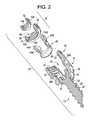
- FIG. 2is an exploded view in cross section of the bone anchor assembly of FIG. 1 ;
- FIG. 3is a side view in cross section of the bone anchor assembly FIG. 1 ;
- FIG. 4is a perspective view of the compression member of the bone anchor assembly of FIG. 1 ;
- FIG. 5is a cross sectional view of the compression member of the bone anchor assembly FIG. 1 ;
- FIG. 6is an exploded view in cross section of another exemplary embodiment of a bone anchor assembly
- FIG. 7is a side view in cross section of the bone anchor assembly of FIG. 6 ;
- FIG. 8is a perspective view of the compression member of FIG. 6 ;
- FIG. 9is a side view in cross section of the compression member of FIG. 6 ;
- FIG. 10is an exploded view in cross section of another exemplary embodiment of a bone anchor assembly
- FIG. 11is a side view in cross section of the bone anchor assembly of FIG. 6 ;
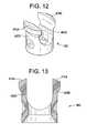
- FIG. 12is a perspective view of the compression member of FIG. 6 ;
- FIG. 13is a side view in cross section of the compression member of FIG. 6 ;
- FIG. 14is a side view in cross section of another exemplary embodiment of a bone anchor assembly
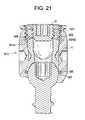
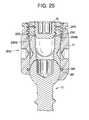
- FIGS. 15-25are side views in cross section of other exemplary embodiments of a bone anchor assembly.
- FIG. 26is a side view in cross section of a prior art bone screw assembly.
- an elementmeans one element or more than one element.
- FIGS. 1-5illustrate an exemplary embodiment of a bone anchor assembly 10 including a bone anchor 12 , a receiver member 14 for receiving a spinal fixation element, such as a spinal rod 22 , to be coupled to the bone anchor 12 , and a closure mechanism 16 to capture a spinal fixation element within the receiver member 14 and fix the spinal fixation element with respect to the receiver member 14 .
- the bone anchor 12includes a proximal head 18 and a distal shaft 20 configured to engage bone.
- the receiver member 14has a proximal end 26 having a pair of spaced apart receiver member arms 28 A, 28 B defining a recess 30 therebetween and a distal end 32 having a distal end surface 34 defining opening 33 through which at least a portion of the bone anchor 12 extends.
- the closure mechanism 16may be positionable between and may engage the arms 28 A, 28 B to capture a spinal fixation element, e.g., spinal rod 22 , within the receiver member 14 and fix the spinal fixation element with respect to the receiver member
- the proximal head 16 of the bone anchor 12 in the exemplary embodimentis generally in the shape of a truncated sphere having a planar proximal surface 36 and an approximately spherically shaped distal surface 38 .
- the exemplary bone anchor assemblyis a polyaxial bone screw designed for posterior implantation in the pedicle or lateral mass of a vertebra.
- the proximal head 18 of the bone anchor 12engages the distal end 32 of the receiver member 14 in a ball and socket like arrangement in which the proximal head 18 , and thus the distal shaft 20 , can pivot relative to the receiver member 14 .
- the distal surface 38 of the proximal head 18 of the bone anchor 12 and the mating surface within the distal end 32 of the receiver member 14may have any shape that facilitates this ball and socket like arrangement, including, for example, spherical (as illustrated), toroidal, conical, frustoconical, and any combinations of these shapes.
- the distal shaft 20 of the bone anchor 12may be configured to engage bone and, in the illustrated embodiment, includes an external bone engaging thread 40 .
- the thread form for the distal shaft 20including the number of threads, the pitch, major and minor diameter, and thread shape, may be selected to facilitate connection with bone. Examples of exemplary thread forms are disclosed in U.S. Patent Application Publication No. 2011-0288599, filed May 18, 2011, and U.S. Patent Application Publication No. US 2013-0053901, filed Aug. 22, 2012, both of which are incorporated herein by reference.
- the distal shaft 20may include other structures for engaging bone, including a hook.
- the distal shaft 20 of the bone anchor 12may be cannulated, having a central passage or cannula extending the length of the bone anchor to facilitate delivery of the bone anchor over a guide wire in, for example, minimally invasive procedures.
- the other components of the bone anchor assemblyincluding the closure member 16 , the receiver member 14 , and the compression member 60 (discussed below) may be cannulated or otherwise have an opening to permit the respective component to be delivered over a guide wire.
- the distal shaft 20may also include one or more side wall openings or fenestrations that communicate with the cannula to permit bone in-growth or to permit the dispensing of bone cement or other materials through the bone anchor 10 .
- the side wall openingsmay extend radially from the cannula through the side wall of the distal shaft 20 .
- Exemplary systems for delivering bone cement to the bone anchor assembly 10 and alternative bone anchor configurations for facilitating cement deliveryare described in U.S. Patent Application Publication No. 2010/0114174, which is hereby incorporated herein by reference.
- the distal shaft 20 of the bone anchor 12may also be coated with materials to permit bone growth, such as, for example, hydroxyl apatite, and the bone anchor assembly 10 may be coated all or in-part with anti-infective materials, such as, for example, tryclosan.
- the proximal end 26 of the receiver member 14 of the exemplary bone anchor assembly 10includes a pair of spaced apart arms 28 A, 28 B defining the U-shaped recess 30 therebetween for receiving a spinal fixation element. e.g., a spinal rod.
- Each receiver member arm 28 A, 28 B of the proximal end 26 of the receiver member 14extends from the distal end 32 of the receiver member 14 to a free end.
- the outer surface of each arm 28 A, 28 Bmay include a feature, such as a recess, dimple, notch, projection, or the like, to facilitate connection of the receiver member 14 and, thus, the bone anchor assembly 10 , to instruments.
- each arm 28 A, 28 Bmay include an arcuate groove 35 at the respective free end of the arms. Such grooves are described in more detail in U.S. Pat. No. 7,179,261, which is incorporated herein by reference. At least a portion of the proximal end surface 48 of the receiver member 12 defines a plane Y, as illustrated in FIG. 3 .
- the distal end 32 of the receiver member 14includes a distal end surface 34 which is generally annular in shape defining a circular opening through which at least a portion of the bone anchor 12 extends.
- a distal end surface 34which is generally annular in shape defining a circular opening through which at least a portion of the bone anchor 12 extends.
- the distal shaft 20 of the bone anchor 12may extend through the opening.
- At least a portion of the distal end surface 34defines a plane X.
- the receiver member 14includes a central passage 37 extending between the proximal end 26 and the distal end 32 .
- the central passage 37communicates with the opening 33 in the distal end surface 34 of the distal end 32 of the receiver member 14 .
- the central passage 37 and the receiver member 14having a common central longitudinal axis L extending between the proximal end 26 and the distal end 32 of the receiver member 14 .
- the exemplary bone anchor assemblyis a rigid polyaxial screw in which the bone anchor 12 can be selectively fixed relative to the receiver member 14 .
- the bone anchor 12Prior to fixation, the bone anchor 12 is movable relative to the receiver member 14 within a cone of angulation generally defined by the geometry of the distal end 32 of the receiver member and the proximal head 18 of the bone anchor 12 .
- the exemplary bone anchoris a favored-angle polyaxial screw in which the cone of angulation is biased in one direction. In this manner, the bone anchor 12 is movable relative to the receiver member 14 in at least a first direction, indicated by arrow A in FIG. 3 and the bone anchor 12 is also movable in at least a second direction, indicated by arrow B in FIG. 3 .
- the shaft 20 of the bone anchor 12is movable more in the direction indicated by arrow A than in the direction indicated by arrow B.
- the distal shaft 20 of the bone anchor 12defines a neutral axis with respect to the receiver member 14 .
- the neutral axisis oriented perpendicular to the plane X defined by the distal end surface 34 and intersects the center point of the opening in the distal end surface 34 through which the distal shaft 20 of the bone anchor 12 extends.
- the neutral axisis oriented at an angle to the central longitudinal axis L of the receiver member 14 in one exemplary manner of providing biased angulation of the bone anchor 12 .
- the plane Y defined by at least a portion of the proximal end surface 48 of the receiver member 14intersects the plane X defined by at least a portion of the distal end surface 34 of the receiver member 12 .
- the proximal end 26 of the receiver member 14may include a proximal first bore coaxial with a first central longitudinal axis N (which is coincident with longitudinal axis L) and a distal second bore coaxial with a second central longitudinal axis (which is coincident with neutral axis) and the first central longitudinal axis N and second central longitudinal axis can intersect one another.
- the angle between the plane X and plane Y and the angle between the first central longitudinal axis N and second longitudinal axiscan be selected to provide the desired degree of biased angulation.
- Examples of favored angled polyaxial screwsare described in more detail in U.S. Patent Application Publication 2003/0055426 and U.S. Pat. No. 6,736,820, both of which are incorporated herein by reference.
- the bone anchor assemblycan be a conventional (non-biased) polyaxial screw in which the bone anchor pivots in the same amount in every direction and has a neutral axis that is coincident with the central longitudinal axis L of the receiver member.
- the spinal fixation elemente.g., a spinal rod 22 in FIG. 3
- contacts an intermediate elemente.g., a compression member 60
- the compression member 60includes a pair of spaced compression member apart arms 62 A and 62 B defining a U-shaped seat 64 for receiving the spinal rod 22 and a distal surface 66 for engaging the proximal head 18 of the bone anchor 12 , as illustrated in FIGS. 3-5 .
- Each compression member arm 62 A and 62 Bincludes an outer wall 65 A,B and an inner wall 67 A,B and a proximal surface 74 A, 74 b of each compression member arm 62 A, 62 B connects the respective outer wall 65 A, 65 B and the respective inner wall 67 A, 67 B.
- Each compression member arm 62 A, 62 B of the compression member 60extends from a distal end 61 of the compression member 60 to a free end that terminates in a respective proximal surface 74 A and 74 B.
- the distal end of the compression member 60is generally annular in shape and has a central opening 61 having a central longitudinal axis that is coincident with the central longitudinal axis L of the central passage 67 when the compression member 60 is positioned within the central passage 37 of the receiver member 14 .
- the distal surface 66surrounds the distal opening in the central passage 67 and is generally annular in shape when viewed from the bottom of the compression member 60 .
- the proximal end 26 of the receiving member 14may be configured to receive a closure mechanism 16 positionable between and engaging the receiver member arms 28 A and 28 B of the receiver member 14 to capture a spinal fixation element, e.g., a spinal rod 22 , within the receiver member 14 , to fix the spinal rod 22 relative to the receiver member 14 , and to fix the bone anchor 12 relative to the receiver member 14 , as illustrated in FIG. 3 .
- the closure mechanism 16may be a single set screw having an outer thread for engaging an inner thread 42 provided on the receiver member arms 28 A and 28 B of the receiver member 14 .
- the closure mechanism 16comprises an outer set screw 70 positionable between and engaging the receiver member arms 28 A and 28 B of the receiver member 14 and an inner set screw 72 positionable within the outer set screw 70 .
- the outer set screw 70is operable to act on the compression member 60 to fix the bone anchor 12 relative to the receiver member 14 .
- the inner set screw 72is operable to act on the spinal rod 22 to fix the spinal rod 22 relative to the receiver member 14 . In this manner, the closure mechanism 16 permits the bone anchor 12 to be fixed relative to the receiver member 14 independently of the spinal rod 22 being fixed to the receiver member 14 .
- the distal surface 100 of the outer set screw 70can engage the proximal end surfaces 74 A and 74 B of the compression member arms 62 A and 62 B of the compression member 60 to force the distal surface 66 of the compression member 60 into contact with the proximal head 18 of bone anchor 12 , which in turn forces the distal surface 38 of the proximal head 18 into the fixed engagement with the distal inner surface of the receiver member 14 .
- the inner set screw 72can engage the spinal rod 22 to force the spinal rod 22 into fixed engagement with the rod seat 64 of the compression member 60 .
- the outer set screw 70 of the exemplary closure mechanism 16includes a first outer thread 76 for engaging the complementary inner thread 42 on the receiver member arms 28 A and 28 B of the receiver member 14 .
- the thread form for the first outer thread 76 and the inner thread 42may be selected to facilitate connection between the components and transfer of the desired axial tightening force.
- the first outer thread 76 and the inner thread 42are square threads. Further exemplary thread forms are described in commonly-owned U.S. Patent Application Publication No. 2013-0096618, filed Oct. 9, 2012, which is incorporated herein by reference.
- the outer set screw 70may have a central passage 96 from a proximal surface 98 of the outer set screw 70 to a distal surface 100 of the outer set screw 74 for receiving the inner set screw 72 .
- the central passage 96may have an inner thread 102 for engaging a complementary outer thread 104 on the inner set screw 72 .
- the thread form for the inner thread 102 and the outer thread 104including the number of threads, the pitch, major and minor diameter, and thread shape, may be selected to facilitate connection between the components and transfer of the desired axial tightening force.
- the inner thread 102 and the outer thread 104are M7 ⁇ 1 metric threads.
- the proximal surface 98 of the outer set screw 70may have one or more drive features to facilitate rotation and advancement of the outer set screw 74 relative to the receiver member 14 .
- the drive featuresare a plurality of cut-outs spaced-apart about the perimeter of the top surface 98 .
- the inner set screw 72may include drive feature for receiving an instrument to rotate and advance the inner set screw 72 relative to the outer set screw 74 .
- the inner set screw 72includes a central passage 108 having a plurality of spaced apart, longitudinally oriented cut-outs for engaging complementary features on an instrument.
- the exemplary bone anchor assembly 10may be used with a spinal fixation element such as rigid spinal rod 22 .
- the spinal rod 22may be constructed from titanium, titanium alloys, stainless steel, cobalt chrome, PEEK, or other materials suitable for rigid fixation.
- the spinal fixation elementmay be a dynamic stabilization member that allows controlled mobility between the instrumented vertebrae.
- outer set screw 70engages with the receiver member arms 28 A and 28 B results in the distal surface 100 of the outer set screw 70 engaging the proximal surface 74 A and 74 B of the compression member arms 62 A and 62 B.
- the outer set screw 70thereby delivers a distal force to the compression member 60 that is transmitted through the compression member 60 to fix the bone anchor 12 relative to the receiver member 14 .
- the proximal surfaces 74 A and 74 B of the compression member arms 62 A and 62can have a shape configured to restrict deformation of the compression member arms 62 A and 62 B, in particular, separation or splaying of the compression member arms 62 A and 62 B (i.e., movement of the arms away from each other) or movement of the compression member arms 62 A and 62 towards each other, during or as a result of tightening, by primarily directing the distal force from the compression member in direction parallel to the central longitudinal axis L and inhibiting transmission of the distal force in a direction non-parallel to the central longitudinal axis L, particularly in a direction away from the central longitudinal axis L.
- the distal surface 66 of the outer set screw 70can have a shape that is complementary to the shape of the proximal surfaces 74 A and 74 B of the compression member arms 62 A and 62 B.
- the proximal surface 74 A and 74 B of each compression member arm 62 A and 62 Bis convex in shape and the distal surface 66 of the outer set screw 70 is concave in shape.
- the convex proximal surfaces 74 A and 74 Bhave a single, constant radius from the respective outer surface 65 A and 65 B and the respective inner surface 67 A and 67 B and the concave distal surface 66 has a constant radius equal to the radius of the convex proximal surfaces 74 A and 74 B.
- the distal surface 902 of the outer set screw 904 and the proximal surfaces 908 A and 908 B of the compression member arms 910 A and 910 Bare flat surfaces.
- the interface between the distal surface 902 and the proximal surfaces 908 A and 908 Bfails to limit or minimize transmission of the axial tightening force in a non-axial direction and therefore fails to minimize or limit the deformation, in particular, the separation or splaying of the compression member arms 910 A and 910 B during axially tightening of the outer set screw 904 .
- FIGS. 6-9illustrate another exemplary bone anchor assembly 210 in which the proximal surfaces 274 A and 274 B of each compression member arm 262 A and 262 B of the compression member 260 has a peaked shape.
- Each peaked proximal surface 274 A and 274 Bhaving a first angled surface 275 A and 275 B that intersects a second angled surface 277 A and 277 B at a peak 279 A and 279 B.
- the distal surface 300 of the outer set screw 270includes a third angled surface 302 that intersects an fourth angled surface 304 to define a V-shaped distal surface 300 complementary in shape to the peaked proximal surfaces 274 A and 274 B.
- the angle of the first angled surface 275 A and 275 B relative to a central longitudinal axis of the compression member 210(which is coincident with the central longitudinal axis L of the receiver member 14 when the compression member 260 is positioned within the central passage 37 of the receiver member 14 ) is equal to the angle of the third angled surface 302 relative to the central longitudinal axis of the outer set screw 270 and the angle of the second angled surface 277 A and 277 B relative to the central longitudinal axis of the compression member 260 is equal to the angle of the fourth angled surface 304 relative to the central longitudinal axis of the outer set screw 270 .
- the peaked interface between the proximal surfaces 274 A and 274 B of the compression member arms 262 A and 262 B and the distal surface 300 of the outer set screweffectively restricts the deformation of the compression member 260 and, in particular, movement of the compression member arms 262 A and 262 B relative to each other.
- FIGS. 10-12illustrate another exemplary bone anchor assembly 410 in which the proximal surfaces 474 A and 474 B of each compression member arm 462 A and 462 B of the compression member 460 is angled from the respective outer wall 465 A and 467 B to the respective inner wall 467 A and 467 B.
- the distal surface 500 of the outer set screw 470is conical in shape having an angle that is complementary to the angle of the angled proximal surfaces 474 A and 474 B.
- the peaked interface between the proximal surfaces 474 A and 474 B of the compression member arms 462 A and 462 B and the distal surface 506 of the outer set screweffectively restricts the deformation of the compression member 460 and, in particular, movement of the compression member arms 462 A and 462 B relative to each other.
- FIG. 14illustrates another exemplary bone anchor assembly 610 in which the proximal surfaces 674 A and 674 B of each compression member arm 662 A and 662 B of the compression member 660 is stepped in shape and has a centrally raised surface 681 A and 681 B.
- the distal surface of the outer set screw 670includes an annular recess 671 that is complementary in size and shape to the centrally raised surface 681 A and 681 B proximal surfaces 674 A and 674 B.
- the centrally raised surface 681 A and 681 B proximal surfaces 674 A and 674 Bseats within the annular recess 671 thereby restricting the deformation of the compression member 660 and, in particular, movement of the compression member arms 662 A and 662 B relative to each other.
- FIGS. 15-25illustrates other exemplary bone anchor assemblies in which the proximal surfaces or the compression member arms and the distal surface of the outer set screw are complementarily configured to restrict the deformation of the compression member and, in particular, movement of the compression member arms relative to each other.
- the distal surface 1000 of the outer set screw 1070is convex in shape and the proximal surfaces of 1074 A and 1074 B of the compression member arms are concave in shape.
- the convex distal surface 1000 and the respective concave proximal surfaces 1074 A and 1074 Beach have a constant radius that extends across the entire surface (when viewed in cross section as in FIG. 15 ) from the outer edge to the inner edge of the surface.
- the radius of the convex distal surface 1000 and radius of the respective concave proximal surfaces 1074 A and 1074 Bare equal.
- the exemplary bone anchor assembly 1010further includes a drag member in the form of a split elastomeric ring 995 that is positioned within an annular groove 997 formed in the inner wall of the receiver member 14 .
- the groove 997 and, thus the ring 995is positioned within the receiver member 14 such that the ring 995 engages the proximal head 18 of the bone anchor 12 above the center point CP of the head 18 or above a line 1002 that intersects the center point CP of the head 18 and is oriented orthogonal to the longitudinal axis of receiver member 14 when the bone anchor 12 is in the neutral position, as illustrated in FIG. 15 .
- the distal surface 1100 of the outer set screw 1170includes a projection that is convex in shape and the proximal surfaces of 1174 A and 1174 B of the compression member arms each include a complementary shaped concave recess in which the convex projection on the distal surface 1100 of the outer set screw can be seated.
- the proximal surfaces of 1274 A and 1274 B of the compression member armseach include a convex projection and the distal surface 1200 of the outer set screw 1270 includes a complementary shaped concave recess or groove in which the convex projections on the proximal surfaces 1274 A and 1274 B can be seated.
- the distal surface 1300 of the outer set screw 1370includes a projection that is convex in shape and the proximal surfaces 1374 A and 1374 B of the compression member arms each have a rectilinear shaped groove (when viewed in cross section as in FIG. 18 ) that receives the convex projection of the distal surface 1300 of the outer set screw 1370 .
- the proximal surfaces of 1474 A and 1474 B of the compression member armseach include a convex projection and the distal surface 1400 of the outer set screw 1470 includes a V-shaped recess or groove that receives the convex projections on the proximal surfaces of 1474 A and 1474 B.
- the distal surface 1500 of the outer set screw 1570is peaked having a first angled surface that intersects a second angled surface at a peak and the proximal surfaces of 1574 A and 1574 B of the compression member arms are concave in shape.
- the distal surface 1600 of the outer set screw 1670includes a projection that is convex in shape and the proximal surfaces 1674 A and 1674 B of the compression member arms each have a V-shaped groove (when viewed in cross section as in FIG. 21 ) that receives the convex projection of the distal surface 1600 of the outer set screw 1670 .
- the distal surface 1700 of the outer set screw 1770includes a projection that is rectilinear in shape and the proximal surfaces 1774 A and 1774 B of the compression member arms each have a complementary shaped rectilinear groove (when viewed in cross section as in FIG. 22 ) that receives the rectilinear projection of the distal surface 1700 of the outer set screw 1770 .
- the distal surface 1800 of the outer set screw 1870has a peaked projection that has a first angled surface that intersects a second angled surface at a peak and the proximal surfaces 1874 A and 1874 B of the compression member arms each have a complementary shaped V-shaped groove (when viewed in cross section as in FIG. 23 ) that receives the peaked shaped projection of the distal surface 1800 of the outer set screw 1870 .
- the distal surface 1900 of the outer set screw 1970is peaked having a first angled surface that intersects a second angled surface at a peak and the proximal surfaces 1974 A and 1974 B of the compression member arms are V-shaped (when viewed in cross section as in FIG. 24 ).
- the proximal surfaces 2084 A and 2084 B of the compression member armseach have a peaked projection that has a first angled surface that intersects a second angled surface at a peak and the distal surface 2000 of the outer set screw 2070 has a complementary shaped V-shaped groove (when viewed in cross section as in FIG. 25 ) that receives the peaked shaped projections of the proximal surfaces 2084 A and 2084 B.
Landscapes
- Health & Medical Sciences (AREA)
- Orthopedic Medicine & Surgery (AREA)
- Life Sciences & Earth Sciences (AREA)
- Neurology (AREA)
- Surgery (AREA)
- Heart & Thoracic Surgery (AREA)
- Engineering & Computer Science (AREA)
- Biomedical Technology (AREA)
- Nuclear Medicine, Radiotherapy & Molecular Imaging (AREA)
- Medical Informatics (AREA)
- Molecular Biology (AREA)
- Animal Behavior & Ethology (AREA)
- General Health & Medical Sciences (AREA)
- Public Health (AREA)
- Veterinary Medicine (AREA)
- Surgical Instruments (AREA)
Abstract
Description
Claims (5)
Priority Applications (9)
| Application Number | Priority Date | Filing Date | Title |
|---|---|---|---|
| US14/029,005US9782204B2 (en) | 2012-09-28 | 2013-09-17 | Bone anchor assemblies |
| JP2015534555AJP6227655B2 (en) | 2012-09-28 | 2013-09-18 | Bone anchor assembly |
| EP13773943.9AEP2900155B1 (en) | 2012-09-28 | 2013-09-18 | Bone anchor assemblies |
| CA2886636ACA2886636C (en) | 2012-09-28 | 2013-09-18 | Bone anchor assemblies |
| PCT/US2013/060350WO2014052117A1 (en) | 2012-09-28 | 2013-09-18 | Bone anchor assemblies |
| CN201380050720.2ACN104869926B (en) | 2012-09-28 | 2013-09-18 | bone anchor assembly |
| AU2013324007AAU2013324007B2 (en) | 2012-09-28 | 2013-09-18 | Bone anchor assemblies |
| US15/692,166US10226282B2 (en) | 2012-09-28 | 2017-08-31 | Bone anchor assemblies |
| US16/277,889US10786284B2 (en) | 2012-09-28 | 2019-02-15 | Bone anchor assemblies |
Applications Claiming Priority (2)
| Application Number | Priority Date | Filing Date | Title |
|---|---|---|---|
| US201261707062P | 2012-09-28 | 2012-09-28 | |
| US14/029,005US9782204B2 (en) | 2012-09-28 | 2013-09-17 | Bone anchor assemblies |
Related Child Applications (1)
| Application Number | Title | Priority Date | Filing Date |
|---|---|---|---|
| US15/692,166ContinuationUS10226282B2 (en) | 2012-09-28 | 2017-08-31 | Bone anchor assemblies |
Publications (2)
| Publication Number | Publication Date |
|---|---|
| US20140094849A1 US20140094849A1 (en) | 2014-04-03 |
| US9782204B2true US9782204B2 (en) | 2017-10-10 |
Family
ID=50385883
Family Applications (3)
| Application Number | Title | Priority Date | Filing Date |
|---|---|---|---|
| US14/029,005ActiveUS9782204B2 (en) | 2012-09-28 | 2013-09-17 | Bone anchor assemblies |
| US15/692,166ActiveUS10226282B2 (en) | 2012-09-28 | 2017-08-31 | Bone anchor assemblies |
| US16/277,889ActiveUS10786284B2 (en) | 2012-09-28 | 2019-02-15 | Bone anchor assemblies |
Family Applications After (2)
| Application Number | Title | Priority Date | Filing Date |
|---|---|---|---|
| US15/692,166ActiveUS10226282B2 (en) | 2012-09-28 | 2017-08-31 | Bone anchor assemblies |
| US16/277,889ActiveUS10786284B2 (en) | 2012-09-28 | 2019-02-15 | Bone anchor assemblies |
Country Status (7)
| Country | Link |
|---|---|
| US (3) | US9782204B2 (en) |
| EP (1) | EP2900155B1 (en) |
| JP (1) | JP6227655B2 (en) |
| CN (1) | CN104869926B (en) |
| AU (1) | AU2013324007B2 (en) |
| CA (1) | CA2886636C (en) |
| WO (1) | WO2014052117A1 (en) |
Cited By (17)
| Publication number | Priority date | Publication date | Assignee | Title |
|---|---|---|---|---|
| US20170360482A1 (en)* | 2012-09-28 | 2017-12-21 | Medos International Sarl | Bone Anchor Assemblies |
| US10201377B2 (en) | 2008-02-04 | 2019-02-12 | Medos International Sarl | Methods for correction of spinal deformities |
| US10238441B2 (en) | 2013-03-14 | 2019-03-26 | Medos International Sàrl | Bottom-loading bone anchor assemblies and methods |
| US10321938B2 (en) | 2013-03-14 | 2019-06-18 | Medos International Sàrl | Locking compression members for use with bone anchor assemblies and methods |
| US10342582B2 (en) | 2013-03-14 | 2019-07-09 | DePuy Synthes Products, Inc. | Bone anchor assemblies and methods with improved locking |
| US10413342B2 (en) | 2013-03-14 | 2019-09-17 | Medos International Sárl | Bone anchor assemblies with multiple component bottom loading bone anchors |
| US11191570B2 (en) | 2017-05-03 | 2021-12-07 | Advance Research System, Llc | Extension ready spinal support systems |
| US11219473B2 (en)* | 2020-03-31 | 2022-01-11 | Warsaw Orthopedic, Inc. | Pop-on-cap assemblies having splay-resisting features and anti-splay features for spinal surgery with wide features allowing purposeful splay by trans-cap distal force |
| US11627995B2 (en) | 2020-12-21 | 2023-04-18 | Warsaw Orthopedic, Inc. | Locking-cap module and connector |
| US11627992B2 (en) | 2020-12-21 | 2023-04-18 | Warsaw Orthopedic, Inc. | Locking-cap module and connector |
| US11648037B2 (en) | 2017-05-03 | 2023-05-16 | Advance Research System, Llc | Extension-ready spinal support system with vascular-safe pedicle screw |
| US11751916B2 (en) | 2009-06-15 | 2023-09-12 | Roger P. Jackson | Pivotal bone anchor assembly with polyaxial screw having frusto-conical upper surface |
| US11911075B2 (en) | 2012-01-10 | 2024-02-27 | Roger P. Jackson | Pivotal bone anchor assembly with increased shank angulation |
| US11957391B2 (en) | 2021-11-01 | 2024-04-16 | Warsaw Orthopedic, Inc. | Bone screw having an overmold of a shank |
| US20240216020A1 (en)* | 2007-05-23 | 2024-07-04 | Roger P. Jackson | Pivotal bone anchor screw with nested two-piece closure and independent locking twist-in-place insert |
| US12076055B2 (en) | 2013-01-28 | 2024-09-03 | Roger P. Jackson | Pivotal bone anchor assembly with favored-angle receiver having upper tool engagement grooves and break-off extensions |
| US12127766B2 (en) | 2021-03-05 | 2024-10-29 | Medos International Sàrl | Selectively locking polyaxial screw |
Families Citing this family (26)
| Publication number | Priority date | Publication date | Assignee | Title |
|---|---|---|---|---|
| US9980753B2 (en)* | 2009-06-15 | 2018-05-29 | Roger P Jackson | pivotal anchor with snap-in-place insert having rotation blocking extensions |
| US10603083B1 (en)* | 2010-07-09 | 2020-03-31 | Theken Spine, Llc | Apparatus and method for limiting a range of angular positions of a screw |
| JP5865479B2 (en)* | 2011-03-24 | 2016-02-17 | ロジャー・ピー・ジャクソン | Multiaxial bone anchor with compound joint and pop-mounted shank |
| US9763702B2 (en)* | 2012-11-16 | 2017-09-19 | DePuy Synthes Products, Inc. | Bone fixation assembly |
| US9433445B2 (en) | 2013-03-14 | 2016-09-06 | DePuy Synthes Products, Inc. | Bone anchors and surgical instruments with integrated guide tips |
| US20140277153A1 (en) | 2013-03-14 | 2014-09-18 | DePuy Synthes Products, LLC | Bone Anchor Assemblies and Methods With Improved Locking |
| US20150073488A1 (en)* | 2013-09-09 | 2015-03-12 | James A. Rinner | Spinal stabilization system |
| CN104207836A (en)* | 2014-09-04 | 2014-12-17 | 浙江嘉佑医疗器械有限公司 | Pedicle screw special for PLIF (Posterior Lumbar Interbody Fusion) |
| US10543021B2 (en) | 2014-10-21 | 2020-01-28 | Roger P. Jackson | Pivotal bone anchor assembly having an open ring positioner for a retainer |
| CN104323847B (en)* | 2014-10-30 | 2017-10-31 | 哈尔滨医科大学 | Intramedullary nail with lock |
| US9987066B2 (en) | 2014-12-15 | 2018-06-05 | Medos International Sarl | Bone anchor driver and methods |
| US9655656B2 (en)* | 2015-01-20 | 2017-05-23 | Amendia, Inc. | Modular pedicle screw assembly with a snap tulip |
| US9833263B2 (en) | 2015-04-13 | 2017-12-05 | Medos International Sarl | Bone anchor assemblies with orientation indicator |
| EP3103406B1 (en) | 2015-06-10 | 2017-10-04 | Biedermann Technologies GmbH & Co. KG | Receiving part of a bone anchoring device and bone anchoring device with such a receiving part |
| US9968378B1 (en)* | 2015-07-22 | 2018-05-15 | University Of South Florida | Adaptation sphere saddle |
| US9949731B2 (en)* | 2015-10-07 | 2018-04-24 | Medos International Sàrl | Systems and methods for manipulating bone |
| CN105581831B (en)* | 2015-12-24 | 2017-03-15 | 建湖县人民医院 | A kind of novel combination type pedicle screw-rod locking system |
| US11026730B2 (en)* | 2017-05-10 | 2021-06-08 | Medos International Sarl | Bone anchors with drag features and related methods |
| US10610265B1 (en) | 2017-07-31 | 2020-04-07 | K2M, Inc. | Polyaxial bone screw with increased angulation |
| US10700093B1 (en) | 2018-12-20 | 2020-06-30 | Sandisk Technologies Llc | Ferroelectric memory devices employing conductivity modulation of a thin semiconductor material or a two-dimensional charge carrier gas and methods of operating the same |
| US11177284B2 (en)* | 2018-12-20 | 2021-11-16 | Sandisk Technologies Llc | Ferroelectric memory devices containing a two-dimensional charge carrier gas channel and methods of making the same |
| US20210169531A1 (en)* | 2019-12-09 | 2021-06-10 | Globus Medical, Inc. | Dual locking polyaxial screw head |
| US11107516B1 (en) | 2020-02-24 | 2021-08-31 | Sandisk Technologies Llc | Ferroelectric memory devices containing a two-dimensional charge carrier gas channel and methods of making the same |
| USD956233S1 (en)* | 2020-04-24 | 2022-06-28 | Solco Biomedical Co., Ltd. | Cervical screw |
| US12364515B2 (en) | 2021-03-05 | 2025-07-22 | Medos International Sàrl | Multi-feature polyaxial screw |
| CN114343815B (en)* | 2022-03-17 | 2022-06-03 | 长沙市第三医院 | Multi-plane cortical bone screw, bone positioning device and positioning and using method |
Citations (276)
| Publication number | Priority date | Publication date | Assignee | Title |
|---|---|---|---|---|
| US2788045A (en) | 1952-10-06 | 1957-04-09 | Rosan Joseph | Conventional truncated screw threads with small locking thread bonded therebetween |
| US2842180A (en) | 1950-02-23 | 1958-07-08 | Set Screw & Mfg Company | Self-locking threads with locking interference fit |
| US4124318A (en) | 1978-03-23 | 1978-11-07 | General Motors Corporation | Splined assembly with retaining rings |
| EP0129556A1 (en) | 1982-12-17 | 1985-01-02 | Texas Instruments Australia Limited | Motor starting device |
| US4762024A (en) | 1985-07-30 | 1988-08-09 | Dana Corporation | Shaft retaining means for a differential gear assembly |
| US5009017A (en) | 1987-01-20 | 1991-04-23 | Caterpillar Inc. | Retaining pin having a positive keeper means |
| WO1991016020A1 (en) | 1990-04-26 | 1991-10-31 | Danninger Medical Technology, Inc. | Transpedicular screw system and method of use |
| EP0470660A1 (en) | 1990-08-07 | 1992-02-12 | Acromed B.V. | Apparatus for the correction of scoliosis |
| US5129388A (en) | 1989-02-09 | 1992-07-14 | Vignaud Jean Louis | Device for supporting the spinal column |
| US5154719A (en) | 1990-02-19 | 1992-10-13 | Societe De Fabrication De Materiel Orthopedique - Sofamor | Implant for a device for osteosynthesis, in particular of the spine |
| US5306275A (en) | 1992-12-31 | 1994-04-26 | Bryan Donald W | Lumbar spine fixation apparatus and method |
| US5385565A (en) | 1992-09-21 | 1995-01-31 | Danek Medical, Inc. | Tool and method for derotating scoliotic spine |
| US5443467A (en) | 1993-03-10 | 1995-08-22 | Biedermann Motech Gmbh | Bone screw |
| US5486174A (en) | 1993-02-24 | 1996-01-23 | Soprane S.A. | Fastener for the osteosynthesis of the spinal column |
| US5487744A (en) | 1993-04-08 | 1996-01-30 | Advanced Spine Fixation Systems, Inc. | Closed connector for spinal fixation systems |
| US5501684A (en) | 1992-06-25 | 1996-03-26 | Synthes (U.S.A.) | Osteosynthetic fixation device |
| US5520689A (en) | 1992-06-04 | 1996-05-28 | Synthes (U.S.A.) | Osteosynthetic fastening device |
| US5562661A (en) | 1995-03-16 | 1996-10-08 | Alphatec Manufacturing Incorporated | Top tightening bone fixation apparatus |
| US5580246A (en) | 1995-01-30 | 1996-12-03 | Fried; Paula S. | Dental implants and methods for extending service life |
| US5643260A (en) | 1995-02-14 | 1997-07-01 | Smith & Nephew, Inc. | Orthopedic fixation system |
| US5672176A (en) | 1995-03-15 | 1997-09-30 | Biedermann; Lutz | Anchoring member |
| US5782833A (en) | 1996-12-20 | 1998-07-21 | Haider; Thomas T. | Pedicle screw system for osteosynthesis |
| EP0857465A1 (en) | 1997-02-10 | 1998-08-12 | Patrice Francois Diebold | Separable screw for an osteosynthesis plate or for setting two bone fragments |
| US5797911A (en) | 1996-09-24 | 1998-08-25 | Sdgi Holdings, Inc. | Multi-axial bone screw assembly |
| US5879350A (en) | 1996-09-24 | 1999-03-09 | Sdgi Holdings, Inc. | Multi-axial bone screw assembly |
| US5885286A (en) | 1996-09-24 | 1999-03-23 | Sdgi Holdings, Inc. | Multi-axial bone screw assembly |
| DE29903342U1 (en) | 1999-02-24 | 1999-06-02 | Grzibek, Egbert, 97534 Waigolshausen | Fixing element for holding elements of spinal implants |
| US5941882A (en) | 1996-07-02 | 1999-08-24 | Societe Etudes Et Developpements S.E.D. | Medical screw particularly for surgery and emplacement tool |
| US5964591A (en) | 1997-04-09 | 1999-10-12 | Implant Innovations, Inc. | Implant delivery system |
| US5989250A (en) | 1996-10-24 | 1999-11-23 | Spinal Concepts, Inc. | Method and apparatus for spinal fixation |
| US6050997A (en) | 1999-01-25 | 2000-04-18 | Mullane; Thomas S. | Spinal fixation system |
| US6056753A (en) | 1998-07-13 | 2000-05-02 | Jackson; Roger P. | Set screw for use with osteosynthesis apparatus |
| US6068632A (en) | 1998-05-12 | 2000-05-30 | Carchidi; Joseph Edward | Bone tap apparatus |
| US6074391A (en) | 1997-06-16 | 2000-06-13 | Howmedica Gmbh | Receiving part for a retaining component of a vertebral column implant |
| US6077262A (en) | 1993-06-04 | 2000-06-20 | Synthes (U.S.A.) | Posterior spinal implant |
| US6090111A (en) | 1998-06-17 | 2000-07-18 | Surgical Dynamics, Inc. | Device for securing spinal rods |
| US6113601A (en) | 1998-06-12 | 2000-09-05 | Bones Consulting, Llc | Polyaxial pedicle screw having a loosely coupled locking cap |
| US6146383A (en) | 1998-02-02 | 2000-11-14 | Sulzer Orthopadie Ag | Pivotal securing system at a bone screw |
| US6224598B1 (en) | 2000-02-16 | 2001-05-01 | Roger P. Jackson | Bone screw threaded plug closure with central set screw |
| US6224596B1 (en) | 1997-01-06 | 2001-05-01 | Roger P. Jackson | Set screw for use with osteosynthesis apparatus |
| US6251112B1 (en) | 2000-04-18 | 2001-06-26 | Roger P. Jackson | Thin profile closure cap for open ended medical implant |
| US6258090B1 (en) | 2000-04-28 | 2001-07-10 | Roger P. Jackson | Closure for open ended medical implant and removal tool |
| US6261287B1 (en) | 1992-03-02 | 2001-07-17 | Stryker Trauma Gmbh | Apparatus for bracing vertebrae |
| US6280442B1 (en) | 1999-09-01 | 2001-08-28 | Sdgi Holdings, Inc. | Multi-axial bone screw assembly |
| US6296642B1 (en) | 1998-11-09 | 2001-10-02 | Sdgi Holdings, Inc. | Reverse angle thread for preventing splaying in medical devices |
| US6302888B1 (en) | 1999-03-19 | 2001-10-16 | Interpore Cross International | Locking dovetail and self-limiting set screw assembly for a spinal stabilization member |
| US6355038B1 (en) | 1998-09-25 | 2002-03-12 | Perumala Corporation | Multi-axis internal spinal fixation |
| US6379356B1 (en) | 2000-04-26 | 2002-04-30 | Roger P. Jackson | Closure for open ended medical implant |
| US6402757B1 (en) | 1999-03-12 | 2002-06-11 | Biomet, Inc. | Cannulated fastener system for repair of bone fracture |
| US6440132B1 (en) | 2000-05-24 | 2002-08-27 | Roger P. Jackson | Open head bone screw closure with threaded boss |
| US6454772B1 (en) | 2000-12-08 | 2002-09-24 | Roger P. Jackson | Set screw for medical implant with gripping side slots |
| US6454768B1 (en) | 2000-12-05 | 2002-09-24 | Roger P. Jackson | Removable gripping set screw |
| US6458132B2 (en) | 2000-03-15 | 2002-10-01 | Gil-Woon Choi | Spine supporting system |
| US6475218B2 (en) | 2000-06-30 | 2002-11-05 | Sofamor, S.N.C. | Spinal implant for an osteosynthesis device |
| US6485491B1 (en) | 2000-09-15 | 2002-11-26 | Sdgi Holdings, Inc. | Posterior fixation system |
| US6488681B2 (en) | 2001-01-05 | 2002-12-03 | Stryker Spine S.A. | Pedicle screw assembly |
| US20030055426A1 (en) | 2001-09-14 | 2003-03-20 | John Carbone | Biased angulation bone fixation assembly |
| EP1295566A1 (en) | 1999-06-30 | 2003-03-26 | Surgival Co., S.A. | Polyaxial vertebral fixing system |
| US6540748B2 (en) | 1999-09-27 | 2003-04-01 | Blackstone Medical, Inc. | Surgical screw system and method of use |
| US20030073996A1 (en) | 2001-10-17 | 2003-04-17 | Doubler Robert L. | Split ring bone screw for a spinal fixation system |
| US20030100896A1 (en) | 2001-11-27 | 2003-05-29 | Lutz Biedermann | Element with a shank and a holding element connected to it for connecting to a rod |
| US20030153911A1 (en) | 2002-02-13 | 2003-08-14 | Endius Incorporated | Apparatus for connecting a longitudinal member to a bone portion |
| US6629977B1 (en) | 1999-11-15 | 2003-10-07 | Arthrex, Inc. | Tapered bioabsorbable interference screw and method for endosteal fixation of ligaments |
| US6663656B2 (en) | 2001-02-26 | 2003-12-16 | Arthrex, Inc. | Torque driver for interference screw |
| US20040049190A1 (en) | 2002-08-09 | 2004-03-11 | Biedermann Motech Gmbh | Dynamic stabilization device for bones, in particular for vertebrae |
| US6723100B2 (en) | 2001-07-27 | 2004-04-20 | Biedermann Motech Gmbh | Bone screw and fastening tool for same |
| US6726687B2 (en) | 2000-12-08 | 2004-04-27 | Jackson Roger P | Closure plug for open-headed medical implant |
| US6726480B1 (en) | 1997-05-24 | 2004-04-27 | Straumann Holding Ag | Support for sustaining and/or forming a dental prosthesis |
| US6730089B2 (en) | 2002-08-26 | 2004-05-04 | Roger P. Jackson | Nested closure plug and set screw with break-off heads |
| US6736820B2 (en) | 2000-11-10 | 2004-05-18 | Biedermann Motech Gmbh | Bone screw |
| US6740086B2 (en) | 2002-04-18 | 2004-05-25 | Spinal Innovations, Llc | Screw and rod fixation assembly and device |
| US6755836B1 (en) | 2002-12-20 | 2004-06-29 | High Plains Technology Group, Llc | Bone screw fastener and apparatus for inserting and removing same |
| WO2004058081A1 (en) | 2002-12-20 | 2004-07-15 | High Plains Technology Group, Llc | Bone screw fastener and apparatus for inserting and removing same |
| US20040162560A1 (en) | 2003-02-19 | 2004-08-19 | Raynor Donald E. | Implant device including threaded locking mechanism |
| US20040186473A1 (en) | 2003-03-21 | 2004-09-23 | Cournoyer John R. | Spinal fixation devices of improved strength and rigidity |
| US6835196B2 (en) | 2001-03-27 | 2004-12-28 | Biedermann Motech Gmbh | Anchoring element |
| US6843790B2 (en) | 2001-03-27 | 2005-01-18 | Bret A. Ferree | Anatomic posterior lumbar plate |
| US20050055026A1 (en) | 2002-10-02 | 2005-03-10 | Biedermann Motech Gmbh | Bone anchoring element |
| US6869433B2 (en) | 2001-01-12 | 2005-03-22 | Depuy Acromed, Inc. | Polyaxial screw with improved locking |
| US20050080415A1 (en) | 2003-10-14 | 2005-04-14 | Keyer Thomas R. | Polyaxial bone anchor and method of spinal fixation |
| US6884244B1 (en) | 2000-06-06 | 2005-04-26 | Roger P. Jackson | Removable medical implant closure for open headed implants |
| US20050154391A1 (en) | 2003-12-30 | 2005-07-14 | Thomas Doherty | Bone anchor assemblies |
| US20050154393A1 (en) | 2003-12-30 | 2005-07-14 | Thomas Doherty | Bone anchor assemblies and methods of manufacturing bone anchor assemblies |
| US20050182401A1 (en) | 2003-05-02 | 2005-08-18 | Timm Jens P. | Systems and methods for spine stabilization including a dynamic junction |
| US20050187548A1 (en) | 2004-01-13 | 2005-08-25 | Butler Michael S. | Pedicle screw constructs for spine fixation systems |
| EP1570974A2 (en) | 2004-03-01 | 2005-09-07 | Centre d'Etude et de Recherche pour l'Automobile ( CERA) | Method for laminating a flexible layer on a rigid element and method for decorating said rigid element |
| US20050216003A1 (en) | 2004-03-03 | 2005-09-29 | Biedermann Motech Gmbh | Bone anchoring element for anchoring in a bone or vertebra, and stabilization device with such a bone anchoring element |
| US20050228326A1 (en)* | 2004-03-31 | 2005-10-13 | Depuy Spine, Inc. | Head-to-head connector spinal fixation system |
| US20050273101A1 (en) | 2004-05-28 | 2005-12-08 | Aesculap Ag & Co. Kg | Bone screw and osteosynthesis device |
| US20050277928A1 (en) | 2004-06-14 | 2005-12-15 | Boschert Paul F | Spinal implant fixation assembly |
| US6981973B2 (en) | 2003-08-11 | 2006-01-03 | Mckinley Laurence M | Low profile vertebral alignment and fixation assembly |
| US20060025771A1 (en) | 2000-08-23 | 2006-02-02 | Jackson Roger P | Helical reverse angle guide and advancement structure with break-off extensions |
| US6997927B2 (en) | 2000-12-08 | 2006-02-14 | Jackson Roger P | closure for rod receiving orthopedic implant having a pair of spaced apertures for removal |
| US7018378B2 (en) | 2000-12-27 | 2006-03-28 | Biedermann Motech Gmbh | Screw |
| US7022122B2 (en) | 1997-01-22 | 2006-04-04 | Synthes (U.S.A.) | Device for connecting a longitudinal bar to a pedicle screw |
| US20060083603A1 (en) | 2000-08-23 | 2006-04-20 | Jackson Roger P | Reverse angled threadform with anti-splay clearance |
| US20060100622A1 (en) | 2004-11-10 | 2006-05-11 | Jackson Roger P | Polyaxial bone screw with helically wound capture connection |
| US20060100621A1 (en) | 2004-11-10 | 2006-05-11 | Jackson Roger P | Polyaxial bone screw with discontinuous helically wound capture connection |
| US20060149241A1 (en)* | 2002-04-18 | 2006-07-06 | Marc Richelsoph | Screw and rod fixation assembly and device |
| US20060161153A1 (en) | 2004-10-25 | 2006-07-20 | Alphaspine, Inc. | Pedicle screw systems and methods of assembling/installing the same |
| US7083621B2 (en) | 2003-04-25 | 2006-08-01 | Sdgi Holdings, Inc. | Articulating spinal fixation rod and system |
| US7087057B2 (en) | 2003-06-27 | 2006-08-08 | Depuy Acromed, Inc. | Polyaxial bone screw |
| EP1694229A1 (en) | 2003-12-17 | 2006-08-30 | SDGI Holdings, Inc. | Device for osteosynthesis of the spine |
| US20060200128A1 (en) | 2003-04-04 | 2006-09-07 | Richard Mueller | Bone anchor |
| US20060264933A1 (en) | 2005-05-04 | 2006-11-23 | Baker Daniel R | Multistage spinal fixation locking mechanism |
| US7179261B2 (en) | 2003-12-16 | 2007-02-20 | Depuy Spine, Inc. | Percutaneous access devices and bone anchor assemblies |
| US7186255B2 (en) | 2004-08-12 | 2007-03-06 | Atlas Spine, Inc. | Polyaxial screw |
| US20070055244A1 (en) | 2004-02-27 | 2007-03-08 | Jackson Roger P | Dynamic fixation assemblies with inner core and outer coil-like member |
| US7198625B1 (en) | 2003-10-01 | 2007-04-03 | Stryker Corporation | Surgical instrument with retractable sheath |
| EP1774919A1 (en) | 2005-10-12 | 2007-04-18 | BIEDERMANN MOTECH GmbH | Poly-axial screw pivotable in a single plane |
| US7211086B2 (en) | 2001-12-28 | 2007-05-01 | Biedermann Motech Gmbh | Locking device for securing a rod-shaped element in a holding element connected to a shank |
| US20070118117A1 (en) | 2005-10-20 | 2007-05-24 | Ebi, L.P. | Bone fixation assembly |
| US20070118123A1 (en) | 2005-11-21 | 2007-05-24 | Strausbaugh William L | Polyaxial bone anchors with increased angulation |
| US7223268B2 (en) | 2001-11-27 | 2007-05-29 | Biedermann Mötech GmbH | Locking device for securing a rod-shaped element in a holding element connected to a shank |
| US20070123870A1 (en) | 2005-07-18 | 2007-05-31 | Jeon Dong M | Bi-polar screw assembly |
| US20070123862A1 (en) | 2004-10-25 | 2007-05-31 | Warnick David R | Bone fixation system and method for using the same |
| EP1795134A1 (en) | 2005-11-17 | 2007-06-13 | BIEDERMANN MOTECH GmbH | Polyaxial screw for flexible rod |
| US7235075B1 (en) | 2002-05-21 | 2007-06-26 | Peter Metz-Stavenhagen | Anchoring element for securing a rod on a vertebra |
| US7261716B2 (en) | 1999-12-23 | 2007-08-28 | Karl Storz Gmbh & Co. Kg | Biodegradable interference screw and tool for attaching a transplant to a bone |
| US7264621B2 (en) | 2004-06-17 | 2007-09-04 | Sdgi Holdings, Inc. | Multi-axial bone attachment assembly |
| US20070265621A1 (en) | 2006-04-06 | 2007-11-15 | Wilfried Matthis | Bone anchoring device |
| US20070270813A1 (en) | 2006-04-12 | 2007-11-22 | Laszlo Garamszegi | Pedicle screw assembly |
| US20070293862A1 (en) | 2005-09-30 | 2007-12-20 | Jackson Roger P | Dynamic stabilization connecting member with elastic core and outer sleeve |
| US7322981B2 (en) | 2003-08-28 | 2008-01-29 | Jackson Roger P | Polyaxial bone screw with split retainer ring |
| US7325470B2 (en) | 2005-06-16 | 2008-02-05 | Orthohelix Surgical Designs, Inc. | Self-centering screw and retaining screw driver for use in surgery |
| US20080045953A1 (en) | 2006-07-14 | 2008-02-21 | Laszlo Garamszegi | Pedicle screw assembly with inclined surface seat |
| WO2008024937A2 (en) | 2006-08-23 | 2008-02-28 | Pioneer Surgical Technology, Inc. | Minimally invasive surgical system |
| US20080119852A1 (en) | 2006-11-20 | 2008-05-22 | Dalton Brian E | Bone repair device and method |
| US20080132957A1 (en) | 2006-11-22 | 2008-06-05 | Wilfried Matthis | Bone anchoring device |
| US20080147129A1 (en)* | 2006-11-17 | 2008-06-19 | Lutz Biedermann | Bone anchoring device |
| US20080161859A1 (en)* | 2006-10-16 | 2008-07-03 | Innovative Delta Technology Llc | Bone Screw and Associated Assembly and Methods of Use Thereof |
| US20080200956A1 (en) | 2007-02-19 | 2008-08-21 | Tutela Medicus, Llc | Low Profile Orthopedic Fastener Assembly Having Enhanced Flexibility |
| WO2008119006A1 (en) | 2007-03-27 | 2008-10-02 | Alpinespine Llc | Pedicle screw system configured to receive a straight or a curved rod |
| US20080269805A1 (en) | 2007-04-25 | 2008-10-30 | Warsaw Orthopedic, Inc. | Methods for correcting spinal deformities |
| US20080269809A1 (en) | 2007-03-26 | 2008-10-30 | Laszlo Garamszegi | Bottom-loading pedicle screw assembly |
| US7445627B2 (en) | 2005-01-31 | 2008-11-04 | Alpinespine, Llc | Polyaxial pedicle screw assembly |
| US20080288001A1 (en) | 2007-05-18 | 2008-11-20 | Trace Cawley | Cervical plate locking mechanism and associated surgical method |
| US20080294202A1 (en) | 2005-04-25 | 2008-11-27 | Joseph Peterson | Bone Anchor With Locking Cap and Method of Spinal Fixation |
| US20080312692A1 (en) | 2007-06-15 | 2008-12-18 | Terrence Brennan | Multi-level spinal stabilization system |
| US20090005813A1 (en) | 2007-06-28 | 2009-01-01 | Angela Crall | Apparatus and methods for spinal implants |
| US20090012567A1 (en)* | 2006-03-31 | 2009-01-08 | Lutz Biedermann | Locking assembly for securing a rod member in a receiver part for use in spinal or trauma surgery, bone anchoring device with such a locking assembly and tool therefor |
| US20090118772A1 (en) | 2007-06-01 | 2009-05-07 | Jennifer Diederich | Polyaxial bone anchor with increased angulation |
| WO2009073655A1 (en) | 2007-12-04 | 2009-06-11 | Cormed Nv/Sa | Spinal fixation assembly |
| EP2070485A1 (en) | 2007-12-13 | 2009-06-17 | Biedermann Motech GmbH | Anchoring device for anchoring a rod in bones or vertebrae |
| US20090163962A1 (en) | 2007-12-20 | 2009-06-25 | Aesculap Implant Systems, Inc. | Locking device introducer instrument |
| US7559943B2 (en) | 2004-06-09 | 2009-07-14 | Zimmer Spine, Inc. | Spinal fixation device with internal drive structure |
| US20090182384A1 (en) | 2008-01-14 | 2009-07-16 | Warsaw Orthopedic, Inc. | Material combinations for medical device implants |
| US20090198280A1 (en) | 2007-10-24 | 2009-08-06 | Frank Spratt | Assembly for Orthopaedic Surgery |
| US20090216280A1 (en)* | 2008-02-04 | 2009-08-27 | John Hutchinson | Methods for Correction of Spinal Deformities |
| US20090228053A1 (en) | 2008-03-10 | 2009-09-10 | Eric Kolb | Derotation instrument with reduction functionality |
| US20090228051A1 (en) | 2008-03-10 | 2009-09-10 | Eric Kolb | Bilateral vertebral body derotation system |
| US20090254125A1 (en)* | 2008-04-03 | 2009-10-08 | Daniel Predick | Top Loading Polyaxial Spine Screw Assembly With One Step Lockup |
| US20090264933A1 (en) | 2008-04-22 | 2009-10-22 | Warsaw Orthopedic, Inc. | Anchors for securing a rod to a vertebral member |
| US7615068B2 (en) | 2003-05-02 | 2009-11-10 | Applied Spine Technologies, Inc. | Mounting mechanisms for pedicle screws and related assemblies |
| US7625394B2 (en) | 2005-08-05 | 2009-12-01 | Warsaw Orthopedic, Inc. | Coupling assemblies for spinal implants |
| EP2129310A1 (en) | 2007-03-07 | 2009-12-09 | Roger P. Jackson | Poly axial bone screw with spherical capture, compression insert and alignment and retention structures |
| US20090326587A1 (en) | 2005-07-08 | 2009-12-31 | Biedermann Motech Gmbh | Bone anchoring device |
| US20100004693A1 (en) | 2008-07-01 | 2010-01-07 | Peter Thomas Miller | Cam locking spine stabilization system and method |
| US20100010547A1 (en) | 2001-12-12 | 2010-01-14 | Ldr Medical | Implant for Osseous Anchoring with Polyaxial Head |
| US20100020272A1 (en) | 2006-09-08 | 2010-01-28 | Tae-Su Kim | Mirror effect liquid crystal display device using reflection polarizer |
| US20100023061A1 (en) | 2008-07-24 | 2010-01-28 | Randol David S | Locking mechanism with two-piece washer |
| US7670362B2 (en) | 2003-06-13 | 2010-03-02 | Tyco Healthcare Group Lp | Multiple member interconnect for surgical instrument and absorbable screw fastener |
| US7674277B2 (en) | 2004-12-01 | 2010-03-09 | Warsaw Orthopedic, Inc. | Side-loading bone anchor |
| US7678139B2 (en) | 2004-04-20 | 2010-03-16 | Allez Spine, Llc | Pedicle screw assembly |
| US7686833B1 (en) | 2004-04-02 | 2010-03-30 | Muhanna Nabil L | Ball jointed pedicle screw and rod system |
| US7699876B2 (en) | 2006-11-08 | 2010-04-20 | Ebi, Llc | Multi-axial bone fixation apparatus |
| US20100103099A1 (en) | 2007-05-26 | 2010-04-29 | Moon Key Lee | Pointing device using camera and outputting mark |
| US20100114174A1 (en) | 2008-10-30 | 2010-05-06 | Bryan Jones | Systems and Methods for Delivering Bone Cement to a Bone Anchor |
| WO2010056846A2 (en) | 2008-11-14 | 2010-05-20 | Ortho Innovations, Llc | Locking polyaxial ball and socket fastener |
| US7731736B2 (en) | 2004-06-14 | 2010-06-08 | Zimmer Spine, Inc. | Fastening system for spinal stabilization system |
| US7736380B2 (en) | 2004-12-21 | 2010-06-15 | Rhausler, Inc. | Cervical plate system |
| US20100152785A1 (en) | 2008-12-16 | 2010-06-17 | Abbott Spine Inc. | Coaxially lockable poly-axial bone fastener assemblies |
| US20100160977A1 (en) | 2008-10-14 | 2010-06-24 | Gephart Matthew P | Low Profile Dual Locking Fixation System and Offset Anchor Member |
| US7766946B2 (en) | 2005-07-27 | 2010-08-03 | Frank Emile Bailly | Device for securing spinal rods |
| US20100198272A1 (en) | 2007-07-20 | 2010-08-05 | Thomas Keyer | Polyaxial bone fixation element |
| US20100204735A1 (en) | 2009-02-11 | 2010-08-12 | Gephart Matthew P | Wide Angulation Coupling Members For Bone Fixation System |
| US20100222827A1 (en) | 2009-02-10 | 2010-09-02 | Bryan Griffiths | Screw with variable diameter cannulation and driver |
| US7789900B2 (en) | 2007-12-04 | 2010-09-07 | Expanding Orthopedics, Inc. | Double collet connector assembly for bone anchoring element |
| US20100234891A1 (en) | 2007-08-31 | 2010-09-16 | University Of South Florida | Translational manipulation polyaxial screw head |
| US20100305621A1 (en) | 2009-06-02 | 2010-12-02 | Alphatec Spine, Inc. | Bone screw assembly for limited angulation |
| US7846190B2 (en) | 2003-12-12 | 2010-12-07 | Integra Lifesciences Corporation | Apparatuses, systems and methods for bone fixation |
| US7850718B2 (en) | 2003-05-28 | 2010-12-14 | Spinevision | Connecting device for spinal osteosynthesis |
| US7867257B2 (en) | 2006-03-20 | 2011-01-11 | Synthes Usa, Llc | Poly-axial bone screw mating seat |
| US20110046683A1 (en)* | 2009-08-20 | 2011-02-24 | Lutz Biedermann | Bone anchoring device, tool and method for assembling the same and tool for use with the same |
| US7901413B1 (en) | 2006-07-21 | 2011-03-08 | High Plains Technology Group, Llc | Surgical locking screw and driver arrangement |
| US7922748B2 (en) | 2006-06-16 | 2011-04-12 | Zimmer Spine, Inc. | Removable polyaxial housing for a pedicle screw |
| US20110106179A1 (en) | 2009-10-30 | 2011-05-05 | Warsaw Orthopedic, Inc. | Set Screw Having Variable Pitch Thread for Use With Spinal Implant Systems |
| WO2011059732A1 (en) | 2009-10-28 | 2011-05-19 | Bonovo Orthopedics, Inc. | Pedicle screws and methods of use |
| US7951175B2 (en) | 2005-03-04 | 2011-05-31 | Depuy Spine, Inc. | Instruments and methods for manipulating a vertebra |
| US7951173B2 (en) | 2007-05-16 | 2011-05-31 | Ortho Innovations, Llc | Pedicle screw implant system |
| US20110160778A1 (en) | 2009-11-16 | 2011-06-30 | Nexxt Spine, LLC | Poly-Axial Implant Fixation System |
| US20110160779A1 (en) | 2008-09-05 | 2011-06-30 | Synthes Usa, Llc | Bone fixation assembly |
| US20110190822A1 (en) | 2004-11-16 | 2011-08-04 | James Spitler | Internal Structure Stabilization System for Spanning Three or More Structures |
| US20110213424A1 (en) | 2009-08-12 | 2011-09-01 | Lutz Biedermann | receiving part for receiving a rod for coupling the rod to a bone anchoring element |
| WO2011109009A1 (en) | 2010-03-01 | 2011-09-09 | K2M, Inc. | Bone screw assembly with non-uniform material |
| US8016862B2 (en) | 2006-09-27 | 2011-09-13 | Innovasis, Inc. | Spinal stabilizing system |
| US20110245876A1 (en) | 2010-04-05 | 2011-10-06 | Brumfield David L | Fully-Adjustable bone fixation device |
| US20110245877A1 (en) | 2008-04-15 | 2011-10-06 | Madhavan Pisharodi | Rod and plate system for incremental reduction of the spine |
| US20110251650A1 (en) | 2010-03-29 | 2011-10-13 | Lutz Biedermann | Bone anchoring device |
| WO2011127065A1 (en) | 2010-04-06 | 2011-10-13 | Seaspine, Inc. | System and methods for correcting spinal deformities |
| US20110270322A1 (en) | 2010-05-03 | 2011-11-03 | Olsen Russell G | Surgical fastener and associated systems and methods |
| US8052724B2 (en) | 2003-06-18 | 2011-11-08 | Jackson Roger P | Upload shank swivel head bone screw spinal implant |
| US20110276098A1 (en) | 2010-05-05 | 2011-11-10 | Lutz Biedermann | Receiving part for receiving a rod for coupling the rod to a bone anchoring element, bone anchoring device, method and tool for assembling the same |
| US8057518B2 (en) | 2007-08-31 | 2011-11-15 | Depuy Spine, Inc. | Spanning connector for connecting a spinal fixation element and an offset bone anchor |
| US20110282399A1 (en) | 2007-01-22 | 2011-11-17 | Jackson Roger P | Polyaxial bone screw with cam connection and lock and release insert |
| US20110288592A1 (en) | 2010-03-30 | 2011-11-24 | Aeolin Llc | Side Opening Bone Fastener System |
| US20110288599A1 (en) | 2010-05-19 | 2011-11-24 | Michael Michielli | Bone Anchors |
| US8066744B2 (en) | 2006-11-10 | 2011-11-29 | Warsaw Orthopedic, Inc. | Keyed crown orientation for multi-axial screws |
| US8066745B2 (en) | 2005-07-29 | 2011-11-29 | X-Spine Systems, Inc. | Capless multiaxial screw and spinal fixation assembly and method |
| US8075599B2 (en) | 2005-10-18 | 2011-12-13 | Warsaw Orthopedic, Inc. | Adjustable bone anchor assembly |
| US8083774B2 (en) | 2000-06-23 | 2011-12-27 | Warsaw Orthopedic, Inc. | Percutaneous vertebral fusion system |
| US20120010661A1 (en) | 2003-08-20 | 2012-01-12 | Warsaw Orthopedic, Inc. | Multi-axial orthopedic device and system |
| US8097023B2 (en) | 2003-11-24 | 2012-01-17 | Warsaw Orthopedic, Inc. | Grommet assembly |
| US20120022593A1 (en) | 2010-07-22 | 2012-01-26 | Aesculap Implant Systems, Llc | Semi-dynamic fixation plate system |
| US20120035670A1 (en) | 2009-06-15 | 2012-02-09 | Jackson Roger P | Polyaxial bone anchors with pop-on shank, fully constrained friction fit retainer and lock and release insert |
| US8114134B2 (en) | 2007-06-05 | 2012-02-14 | Spartek Medical, Inc. | Spinal prosthesis having a three bar linkage for motion preservation and dynamic stabilization of the spine |
| WO2012024665A2 (en) | 2010-08-20 | 2012-02-23 | K2M, Inc. | Spinal fixation system |
| WO2012030712A1 (en) | 2010-08-30 | 2012-03-08 | Zimmer Spine, Inc. | Polyaxial pedicle screw |
| US20120059426A1 (en) | 2008-08-01 | 2012-03-08 | Jackson Roger P | Polyaxial bone anchors with pop-on shank, friction fit fully restrained retainer, insert and tool receiving features |
| US20120059425A1 (en) | 2010-03-08 | 2012-03-08 | Markku Biedermann | Locking Element for a Polyaxial Bone Anchor, Bone Plate Assembly and Tool |
| WO2012035479A2 (en) | 2010-09-13 | 2012-03-22 | Facetmed Ltd. | Spinal fixation system and pedicle screw therefor |
| US20120078307A1 (en) | 2010-09-28 | 2012-03-29 | Raj Nihalani | Pedicle screws and dynamic adaptors |
| US20120083845A1 (en) | 2010-10-05 | 2012-04-05 | Spartek Medical, Inc. | Compound spinal rod and method for dynamic stabilization of the spine |
| US8162989B2 (en) | 2002-11-04 | 2012-04-24 | Altus Partners, Llc | Orthopedic rod system |
| US8167912B2 (en) | 2007-02-27 | 2012-05-01 | The Center for Orthopedic Research and Education, Inc | Modular pedicle screw system |
| WO2012060868A1 (en) | 2010-11-02 | 2012-05-10 | Jackson Roger P | Polyaxial bone anchor with pop-on shank and pivotable retainer |
| EP2455028A1 (en) | 2010-11-22 | 2012-05-23 | Biedermann Technologies GmbH & Co. KG | Polyaxial bone anchoring device |
| US20120136395A1 (en) | 2010-11-24 | 2012-05-31 | Lutz Biedermann | Polyaxial bone anchoring device with enlarged pivot angle |
| US20120143266A1 (en) | 2009-06-15 | 2012-06-07 | Jackson Roger P | Polyaxial bone anchor with open planar retainer, pop-on shank and friction fit insert |
| US8197518B2 (en) | 2007-05-16 | 2012-06-12 | Ortho Innovations, Llc | Thread-thru polyaxial pedicle screw system |
| US8197517B1 (en) | 2007-05-08 | 2012-06-12 | Theken Spine, Llc | Frictional polyaxial screw assembly |
| US20120150239A1 (en) | 2010-10-15 | 2012-06-14 | Laszlo Garamszegi | Fixation screw assembly |
| US20120165882A1 (en) | 2010-12-27 | 2012-06-28 | Lutz Biedermann | Polyaxial bone anchoring device |
| US20120179209A1 (en) | 2010-12-10 | 2012-07-12 | Lutz Biedermann | Receiving part for receiving a rod for coupling the rod to a bone anchoring element and a bone anchoring device |
| US8221471B2 (en) | 2007-05-24 | 2012-07-17 | Aesculap Implant Systems, Llc | Pedicle screw fixation system |
| US20120185003A1 (en) | 2010-12-13 | 2012-07-19 | Lutz Biedermann | Bone anchoring device |
| US20120197313A1 (en) | 2011-01-28 | 2012-08-02 | Warsaw Orthopedic, Inc. | Angled Receiver Wall for Provisionally Fixing a Crown in a Multi-Axial Screw Assembly |
| US8236035B1 (en) | 2009-06-16 | 2012-08-07 | Bedor Bernard M | Spinal fixation system and method |
| US8241341B2 (en) | 2009-03-20 | 2012-08-14 | Spinal Usa, Inc. | Pedicle screws and methods of using the same |
| US20120209336A1 (en) | 2009-06-15 | 2012-08-16 | Jackson Roger P | Polyaxial bone anchor with pop-on shank, friction fit retainer and winged insert |
| US8257396B2 (en) | 2003-06-18 | 2012-09-04 | Jackson Roger P | Polyaxial bone screw with shank-retainer inset capture |
| US8267968B2 (en) | 2009-06-24 | 2012-09-18 | Neuropro Technologies, Inc. | Percutaneous system for dynamic spinal stabilization |
| US20120253404A1 (en) | 2003-05-02 | 2012-10-04 | Rachiotek, Llc | Method for stabilizing a spinal segment |
| US8287576B2 (en) | 2007-10-23 | 2012-10-16 | K2M, Inc. | Mono-axial, taper lock bone screw |
| US8298270B2 (en) | 2006-01-27 | 2012-10-30 | Warsaw Orthopedic, Inc. | Pivoting joints for spinal implants including designed resistance to motion and methods of use |
| US20120277805A1 (en) | 2011-04-29 | 2012-11-01 | Warsaw Orthopedic, Inc. | Rotatable Base Multi-Axial Screw Assembly |
| US8303594B2 (en) | 2008-12-30 | 2012-11-06 | Howmedica Osteonics Corp. | Method and apparatus for removal of tissue |
| US8308782B2 (en) | 2004-11-23 | 2012-11-13 | Jackson Roger P | Bone anchors with longitudinal connecting member engaging inserts and closures for fixation and optional angulation |
| US20120303070A1 (en) | 2005-09-30 | 2012-11-29 | Jackson Roger P | Polyaxial bone anchor assembly with one-piece closure, pressure insert and plastic elongate member |
| US20120316605A1 (en) | 2011-06-13 | 2012-12-13 | Greg Palagi | Taper Lock For A Polyaxial Spinal Rod Screw Assembly |
| US8337530B2 (en) | 2011-03-09 | 2012-12-25 | Zimmer Spine, Inc. | Polyaxial pedicle screw with increased angulation |
| US8343191B2 (en) | 2006-12-22 | 2013-01-01 | Biedermann Technologies Gmbh & Co. Kg | Bone anchoring device |
| US20130013003A1 (en) | 2010-02-23 | 2013-01-10 | K2M, Inc. | Polyaxial bonescrew assembly |
| US8377100B2 (en) | 2000-12-08 | 2013-02-19 | Roger P. Jackson | Closure for open-headed medical implant |
| WO2013028851A1 (en) | 2011-08-25 | 2013-02-28 | Medos International Sarl | Bone anchors |
| US20130096618A1 (en) | 2011-10-14 | 2013-04-18 | Thibault Chandanson | Bone anchor assemblies |
| US20130096623A1 (en) | 2011-09-15 | 2013-04-18 | Lutz Biedermann | Polyaxial bone anchoring device with enlarged pivot angle |
| US20130103093A1 (en) | 2011-08-05 | 2013-04-25 | Lutz Biedermann | Locking device for locking a rod-shaped element in a receiving part of a bone anchor and bone anchor with such a locking device |
| US20130110172A1 (en) | 2011-10-28 | 2013-05-02 | Biedermann Technologies Gmbh & Co. Kg | Locking assembly for a polyaxial bone anchoring device |
| US20130110180A1 (en) | 2011-10-28 | 2013-05-02 | Robert L. Doubler | Top loading polyaxial ball and socket fastener with saddle |
| US8465528B2 (en) | 2007-08-30 | 2013-06-18 | Aesculap Ag | Surgical retaining screw |
| US8491640B1 (en) | 2012-07-02 | 2013-07-23 | James C. Robinson | Bone screw coupling assembly |
| US20130211467A1 (en) | 2012-02-10 | 2013-08-15 | Warsaw Orthopedic, Inc. | Connector and fastener system |
| US8556938B2 (en) | 2009-06-15 | 2013-10-15 | Roger P. Jackson | Polyaxial bone anchor with non-pivotable retainer and pop-on shank, some with friction fit |
| US20140025119A1 (en) | 2012-07-18 | 2014-01-23 | Biedermann Technologies GmbH & Co., KG | Polyaxial bone anchoring device |
| US20140142633A1 (en) | 2012-11-21 | 2014-05-22 | Roger P. Jackson | Splay control closure for open bone anchor |
| US20140277159A1 (en) | 2013-03-14 | 2014-09-18 | DePuy Synthes Products, LLC | Bottom-loading bone anchor assemblies |
| US20140277162A1 (en) | 2013-03-13 | 2014-09-18 | K2M, Inc. | Fixation implant and method of insertion |
| US20140277153A1 (en) | 2013-03-14 | 2014-09-18 | DePuy Synthes Products, LLC | Bone Anchor Assemblies and Methods With Improved Locking |
| US20140277189A1 (en) | 2013-03-14 | 2014-09-18 | DePuy Synthes Products, LLC | Bone anchor assemblies with multiple component bottom loading bone anchors |
| US20140277157A1 (en) | 2013-03-14 | 2014-09-18 | DePuy Synthes Products, LLC | Locking Compression Members for Use With Bone Anchor Assemblies and Methods |
| US20140277158A1 (en) | 2013-03-14 | 2014-09-18 | DePuy Synthes Products, LLC | Bottom-loading bone anchor assemblies and methods |
| US20140277161A1 (en) | 2013-03-14 | 2014-09-18 | Medos International Sarl | Bone Anchor Assemblies and Methods With Improved Locking |
| US8951294B2 (en) | 2009-03-12 | 2015-02-10 | Euros | Spinal implant with a lockable ball joint |
| US9402673B2 (en) | 2012-09-28 | 2016-08-02 | DePuy Synthes Products, Inc. | Devices and methods for breaking and retaining surgical reduction tabs |
| US9433445B2 (en) | 2013-03-14 | 2016-09-06 | DePuy Synthes Products, Inc. | Bone anchors and surgical instruments with integrated guide tips |
Family Cites Families (17)
| Publication number | Priority date | Publication date | Assignee | Title |
|---|---|---|---|---|
| BE469107A (en) | 1945-01-25 | |||
| US7776067B2 (en) | 2005-05-27 | 2010-08-17 | Jackson Roger P | Polyaxial bone screw with shank articulation pressure insert and method |
| US7967850B2 (en) | 2003-06-18 | 2011-06-28 | Jackson Roger P | Polyaxial bone anchor with helical capture connection, insert and dual locking assembly |
| US20050153077A1 (en) | 2003-12-03 | 2005-07-14 | Anthony Gedeon | Method of resisting contaminant build up and oxidation of vehicle surfaces and other surfaces |
| EP1570794A1 (en) | 2004-03-04 | 2005-09-07 | U & I Corporation | Bone fixation apparatus, method and tool for assembling the same |
| US20130144346A1 (en) | 2004-11-23 | 2013-06-06 | Roger P. Jackson | Modular polyaxial bone anchor with retainer having interconnected pieces |
| US7875065B2 (en) | 2004-11-23 | 2011-01-25 | Jackson Roger P | Polyaxial bone screw with multi-part shank retainer and pressure insert |
| US9216041B2 (en)* | 2009-06-15 | 2015-12-22 | Roger P. Jackson | Spinal connecting members with tensioned cords and rigid sleeves for engaging compression inserts |
| US7833252B2 (en) | 2006-01-27 | 2010-11-16 | Warsaw Orthopedic, Inc. | Pivoting joints for spinal implants including designed resistance to motion and methods of use |
| ES2368016T3 (en) | 2008-04-22 | 2011-11-11 | Biedermann Motech Gmbh | INSTRUMENT FOR MOUNTING A BONE ANCHORAGE DEVICE. |
| CN103826560A (en) | 2009-06-15 | 2014-05-28 | 罗杰.P.杰克逊 | Polyaxial Bone Anchor with Socket Stem and Winged Inserts with Friction Fit Compression Collars |
| ES2461843T3 (en) | 2010-12-23 | 2014-05-21 | Biedermann Technologies Gmbh & Co. Kg | Bone anchoring device |
| EP2604204B1 (en)* | 2011-12-13 | 2014-10-01 | Biedermann Technologies GmbH & Co. KG | Monoplanar bone anchoring device with selectable pivot plane |
| US9782204B2 (en)* | 2012-09-28 | 2017-10-10 | Medos International Sarl | Bone anchor assemblies |
| US9763702B2 (en)* | 2012-11-16 | 2017-09-19 | DePuy Synthes Products, Inc. | Bone fixation assembly |
| US10058354B2 (en) | 2013-01-28 | 2018-08-28 | Roger P. Jackson | Pivotal bone anchor assembly with frictional shank head seating surfaces |
| EP2886073B1 (en) | 2013-12-19 | 2017-05-31 | Biedermann Technologies GmbH & Co. KG | Polyaxial bone anchoring device with enlarged pivot angle |
- 2013
- 2013-09-17USUS14/029,005patent/US9782204B2/enactiveActive
- 2013-09-18AUAU2013324007Apatent/AU2013324007B2/enactiveActive
- 2013-09-18JPJP2015534555Apatent/JP6227655B2/enactiveActive
- 2013-09-18EPEP13773943.9Apatent/EP2900155B1/enactiveActive
- 2013-09-18CACA2886636Apatent/CA2886636C/enactiveActive
- 2013-09-18CNCN201380050720.2Apatent/CN104869926B/enactiveActive
- 2013-09-18WOPCT/US2013/060350patent/WO2014052117A1/enactiveApplication Filing
- 2017
- 2017-08-31USUS15/692,166patent/US10226282B2/enactiveActive
- 2019
- 2019-02-15USUS16/277,889patent/US10786284B2/enactiveActive
Patent Citations (340)
| Publication number | Priority date | Publication date | Assignee | Title |
|---|---|---|---|---|
| US2842180A (en) | 1950-02-23 | 1958-07-08 | Set Screw & Mfg Company | Self-locking threads with locking interference fit |
| US2788045A (en) | 1952-10-06 | 1957-04-09 | Rosan Joseph | Conventional truncated screw threads with small locking thread bonded therebetween |
| US4124318A (en) | 1978-03-23 | 1978-11-07 | General Motors Corporation | Splined assembly with retaining rings |
| EP0129556A1 (en) | 1982-12-17 | 1985-01-02 | Texas Instruments Australia Limited | Motor starting device |
| US4762024A (en) | 1985-07-30 | 1988-08-09 | Dana Corporation | Shaft retaining means for a differential gear assembly |
| US5009017A (en) | 1987-01-20 | 1991-04-23 | Caterpillar Inc. | Retaining pin having a positive keeper means |
| US5129388A (en) | 1989-02-09 | 1992-07-14 | Vignaud Jean Louis | Device for supporting the spinal column |
| US5154719A (en) | 1990-02-19 | 1992-10-13 | Societe De Fabrication De Materiel Orthopedique - Sofamor | Implant for a device for osteosynthesis, in particular of the spine |
| US5360431A (en) | 1990-04-26 | 1994-11-01 | Cross Medical Products | Transpedicular screw system and method of use |
| WO1991016020A1 (en) | 1990-04-26 | 1991-10-31 | Danninger Medical Technology, Inc. | Transpedicular screw system and method of use |
| US5474555A (en) | 1990-04-26 | 1995-12-12 | Cross Medical Products | Spinal implant system |
| EP0470660A1 (en) | 1990-08-07 | 1992-02-12 | Acromed B.V. | Apparatus for the correction of scoliosis |
| US6261287B1 (en) | 1992-03-02 | 2001-07-17 | Stryker Trauma Gmbh | Apparatus for bracing vertebrae |
| US6537276B2 (en) | 1992-03-02 | 2003-03-25 | Stryker Trauma Gmbh | Apparatus for bracing vertebrae |
| US5520689A (en) | 1992-06-04 | 1996-05-28 | Synthes (U.S.A.) | Osteosynthetic fastening device |
| US5501684A (en) | 1992-06-25 | 1996-03-26 | Synthes (U.S.A.) | Osteosynthetic fixation device |
| US5385565A (en) | 1992-09-21 | 1995-01-31 | Danek Medical, Inc. | Tool and method for derotating scoliotic spine |
| US5306275A (en) | 1992-12-31 | 1994-04-26 | Bryan Donald W | Lumbar spine fixation apparatus and method |
| US5486174A (en) | 1993-02-24 | 1996-01-23 | Soprane S.A. | Fastener for the osteosynthesis of the spinal column |
| US5443467A (en) | 1993-03-10 | 1995-08-22 | Biedermann Motech Gmbh | Bone screw |
| US5487744A (en) | 1993-04-08 | 1996-01-30 | Advanced Spine Fixation Systems, Inc. | Closed connector for spinal fixation systems |
| US6077262A (en) | 1993-06-04 | 2000-06-20 | Synthes (U.S.A.) | Posterior spinal implant |
| US5580246A (en) | 1995-01-30 | 1996-12-03 | Fried; Paula S. | Dental implants and methods for extending service life |
| US5643260A (en) | 1995-02-14 | 1997-07-01 | Smith & Nephew, Inc. | Orthopedic fixation system |
| US5672176A (en) | 1995-03-15 | 1997-09-30 | Biedermann; Lutz | Anchoring member |
| US5562661A (en) | 1995-03-16 | 1996-10-08 | Alphatec Manufacturing Incorporated | Top tightening bone fixation apparatus |
| US5941882A (en) | 1996-07-02 | 1999-08-24 | Societe Etudes Et Developpements S.E.D. | Medical screw particularly for surgery and emplacement tool |
| US5797911A (en) | 1996-09-24 | 1998-08-25 | Sdgi Holdings, Inc. | Multi-axial bone screw assembly |
| US5879350A (en) | 1996-09-24 | 1999-03-09 | Sdgi Holdings, Inc. | Multi-axial bone screw assembly |
| US5885286A (en) | 1996-09-24 | 1999-03-23 | Sdgi Holdings, Inc. | Multi-axial bone screw assembly |
| US6053917A (en) | 1996-09-24 | 2000-04-25 | Sdgi Holdings, Inc. | Multi-axial bone screw assembly |
| US5989250A (en) | 1996-10-24 | 1999-11-23 | Spinal Concepts, Inc. | Method and apparatus for spinal fixation |
| US5782833A (en) | 1996-12-20 | 1998-07-21 | Haider; Thomas T. | Pedicle screw system for osteosynthesis |
| US6485494B1 (en) | 1996-12-20 | 2002-11-26 | Thomas T. Haider | Pedicle screw system for osteosynthesis |
| US6565567B1 (en) | 1996-12-20 | 2003-05-20 | Thomas T. Haider | Pedicle screw for osteosynthesis |
| US6224596B1 (en) | 1997-01-06 | 2001-05-01 | Roger P. Jackson | Set screw for use with osteosynthesis apparatus |
| US7022122B2 (en) | 1997-01-22 | 2006-04-04 | Synthes (U.S.A.) | Device for connecting a longitudinal bar to a pedicle screw |
| EP0857465A1 (en) | 1997-02-10 | 1998-08-12 | Patrice Francois Diebold | Separable screw for an osteosynthesis plate or for setting two bone fragments |
| US5964591A (en) | 1997-04-09 | 1999-10-12 | Implant Innovations, Inc. | Implant delivery system |
| US6726480B1 (en) | 1997-05-24 | 2004-04-27 | Straumann Holding Ag | Support for sustaining and/or forming a dental prosthesis |
| US6074391A (en) | 1997-06-16 | 2000-06-13 | Howmedica Gmbh | Receiving part for a retaining component of a vertebral column implant |
| US6146383A (en) | 1998-02-02 | 2000-11-14 | Sulzer Orthopadie Ag | Pivotal securing system at a bone screw |
| US6068632A (en) | 1998-05-12 | 2000-05-30 | Carchidi; Joseph Edward | Bone tap apparatus |
| US6113601A (en) | 1998-06-12 | 2000-09-05 | Bones Consulting, Llc | Polyaxial pedicle screw having a loosely coupled locking cap |
| US6090111A (en) | 1998-06-17 | 2000-07-18 | Surgical Dynamics, Inc. | Device for securing spinal rods |
| US6056753A (en) | 1998-07-13 | 2000-05-02 | Jackson; Roger P. | Set screw for use with osteosynthesis apparatus |
| US6355038B1 (en) | 1998-09-25 | 2002-03-12 | Perumala Corporation | Multi-axis internal spinal fixation |
| US6296642B1 (en) | 1998-11-09 | 2001-10-02 | Sdgi Holdings, Inc. | Reverse angle thread for preventing splaying in medical devices |
| US6050997A (en) | 1999-01-25 | 2000-04-18 | Mullane; Thomas S. | Spinal fixation system |
| DE29903342U1 (en) | 1999-02-24 | 1999-06-02 | Grzibek, Egbert, 97534 Waigolshausen | Fixing element for holding elements of spinal implants |
| US6402757B1 (en) | 1999-03-12 | 2002-06-11 | Biomet, Inc. | Cannulated fastener system for repair of bone fracture |
| US6302888B1 (en) | 1999-03-19 | 2001-10-16 | Interpore Cross International | Locking dovetail and self-limiting set screw assembly for a spinal stabilization member |
| EP1295566A1 (en) | 1999-06-30 | 2003-03-26 | Surgival Co., S.A. | Polyaxial vertebral fixing system |
| US6280442B1 (en) | 1999-09-01 | 2001-08-28 | Sdgi Holdings, Inc. | Multi-axial bone screw assembly |
| US20040116929A1 (en) | 1999-09-01 | 2004-06-17 | Barker B. Thomas | Multi-axial bone screw assembly |
| US6660004B2 (en) | 1999-09-01 | 2003-12-09 | Sdgi Holdings, Inc. | Multi-axial bone screw assembly |
| US20100198270A1 (en) | 1999-09-01 | 2010-08-05 | Warsaw Orthopedic, Inc. | Multi-Axial Bone Screw Assembly |
| US7727261B2 (en) | 1999-09-01 | 2010-06-01 | Warsaw Orthopedic, Inc. | Multi-axial bone screw assembly |
| US8298274B2 (en) | 1999-09-01 | 2012-10-30 | Warsaw Orthopedic, Inc. | Multi-axial bone screw assembly |
| US6540748B2 (en) | 1999-09-27 | 2003-04-01 | Blackstone Medical, Inc. | Surgical screw system and method of use |
| US6629977B1 (en) | 1999-11-15 | 2003-10-07 | Arthrex, Inc. | Tapered bioabsorbable interference screw and method for endosteal fixation of ligaments |
| US7261716B2 (en) | 1999-12-23 | 2007-08-28 | Karl Storz Gmbh & Co. Kg | Biodegradable interference screw and tool for attaching a transplant to a bone |
| US6224598B1 (en) | 2000-02-16 | 2001-05-01 | Roger P. Jackson | Bone screw threaded plug closure with central set screw |
| US6361535B2 (en) | 2000-02-16 | 2002-03-26 | Roger P. Jackson | Bone screw threaded plug closure with central set screw |
| US6458132B2 (en) | 2000-03-15 | 2002-10-01 | Gil-Woon Choi | Spine supporting system |
| US6251112B1 (en) | 2000-04-18 | 2001-06-26 | Roger P. Jackson | Thin profile closure cap for open ended medical implant |
| US6379356B1 (en) | 2000-04-26 | 2002-04-30 | Roger P. Jackson | Closure for open ended medical implant |
| US6258090B1 (en) | 2000-04-28 | 2001-07-10 | Roger P. Jackson | Closure for open ended medical implant and removal tool |
| US6440132B1 (en) | 2000-05-24 | 2002-08-27 | Roger P. Jackson | Open head bone screw closure with threaded boss |
| US6884244B1 (en) | 2000-06-06 | 2005-04-26 | Roger P. Jackson | Removable medical implant closure for open headed implants |
| US8083774B2 (en) | 2000-06-23 | 2011-12-27 | Warsaw Orthopedic, Inc. | Percutaneous vertebral fusion system |
| US6475218B2 (en) | 2000-06-30 | 2002-11-05 | Sofamor, S.N.C. | Spinal implant for an osteosynthesis device |
| US20060083603A1 (en) | 2000-08-23 | 2006-04-20 | Jackson Roger P | Reverse angled threadform with anti-splay clearance |
| US20060025771A1 (en) | 2000-08-23 | 2006-02-02 | Jackson Roger P | Helical reverse angle guide and advancement structure with break-off extensions |
| US6485491B1 (en) | 2000-09-15 | 2002-11-26 | Sdgi Holdings, Inc. | Posterior fixation system |
| US20040153077A1 (en) | 2000-11-10 | 2004-08-05 | Lutz Biedermann | Bone screw |
| US7785354B2 (en) | 2000-11-10 | 2010-08-31 | Biedermann Motech Gmbh | Bone screw |
| US6736820B2 (en) | 2000-11-10 | 2004-05-18 | Biedermann Motech Gmbh | Bone screw |
| US20060106383A1 (en) | 2000-11-10 | 2006-05-18 | Biedermann Motech Gmbh | Bone screw |
| US20060084995A1 (en) | 2000-11-10 | 2006-04-20 | Biedermann Motech Gmbh | Bone screw |
| US8409260B2 (en) | 2000-11-10 | 2013-04-02 | Biedermann Technologies Gmbh & Co. Kg | Bone screw |
| US6454768B1 (en) | 2000-12-05 | 2002-09-24 | Roger P. Jackson | Removable gripping set screw |
| US20040186478A1 (en) | 2000-12-08 | 2004-09-23 | Jackson Roger P. | Closure plug for open headed medical implant |
| US6454772B1 (en) | 2000-12-08 | 2002-09-24 | Roger P. Jackson | Set screw for medical implant with gripping side slots |
| US8377100B2 (en) | 2000-12-08 | 2013-02-19 | Roger P. Jackson | Closure for open-headed medical implant |
| US6997927B2 (en) | 2000-12-08 | 2006-02-14 | Jackson Roger P | closure for rod receiving orthopedic implant having a pair of spaced apertures for removal |
| US6726687B2 (en) | 2000-12-08 | 2004-04-27 | Jackson Roger P | Closure plug for open-headed medical implant |
| US7018378B2 (en) | 2000-12-27 | 2006-03-28 | Biedermann Motech Gmbh | Screw |
| US6488681B2 (en) | 2001-01-05 | 2002-12-03 | Stryker Spine S.A. | Pedicle screw assembly |
| US7291153B2 (en) | 2001-01-12 | 2007-11-06 | Debuy Acromed, Inc. | Polyaxial screw with improved locking |
| US6869433B2 (en) | 2001-01-12 | 2005-03-22 | Depuy Acromed, Inc. | Polyaxial screw with improved locking |
| US6663656B2 (en) | 2001-02-26 | 2003-12-16 | Arthrex, Inc. | Torque driver for interference screw |
| US6843790B2 (en) | 2001-03-27 | 2005-01-18 | Bret A. Ferree | Anatomic posterior lumbar plate |
| US6835196B2 (en) | 2001-03-27 | 2004-12-28 | Biedermann Motech Gmbh | Anchoring element |
| US6723100B2 (en) | 2001-07-27 | 2004-04-20 | Biedermann Motech Gmbh | Bone screw and fastening tool for same |
| US20030055426A1 (en) | 2001-09-14 | 2003-03-20 | John Carbone | Biased angulation bone fixation assembly |
| US20040243126A1 (en) | 2001-09-14 | 2004-12-02 | Stryker Spine | Methods for stabilizing bone using spinal fixation devices |
| US6974460B2 (en) | 2001-09-14 | 2005-12-13 | Stryker Spine | Biased angulation bone fixation assembly |
| US20030073996A1 (en) | 2001-10-17 | 2003-04-17 | Doubler Robert L. | Split ring bone screw for a spinal fixation system |
| US7223268B2 (en) | 2001-11-27 | 2007-05-29 | Biedermann Mötech GmbH | Locking device for securing a rod-shaped element in a holding element connected to a shank |
| US20030100896A1 (en) | 2001-11-27 | 2003-05-29 | Lutz Biedermann | Element with a shank and a holding element connected to it for connecting to a rod |
| US20070260246A1 (en) | 2001-11-27 | 2007-11-08 | Biedermann Motech Gmbh | Locking device for securing a rod-shaped element in a holding element connected to a shank |
| US20120328394A1 (en) | 2001-11-27 | 2012-12-27 | Biedermann Technologies Gmbh & Co. Kg | Element with a shank and a holding element connected to it for connecting to a rod |
| US20100010547A1 (en) | 2001-12-12 | 2010-01-14 | Ldr Medical | Implant for Osseous Anchoring with Polyaxial Head |
| US7211086B2 (en) | 2001-12-28 | 2007-05-01 | Biedermann Motech Gmbh | Locking device for securing a rod-shaped element in a holding element connected to a shank |
| US20030153911A1 (en) | 2002-02-13 | 2003-08-14 | Endius Incorporated | Apparatus for connecting a longitudinal member to a bone portion |
| US6740086B2 (en) | 2002-04-18 | 2004-05-25 | Spinal Innovations, Llc | Screw and rod fixation assembly and device |
| US20040193160A1 (en) | 2002-04-18 | 2004-09-30 | Marc Richelsoph | Screw and rod fixation asembly and device |
| US7955363B2 (en) | 2002-04-18 | 2011-06-07 | Aesculap Implant Systems, Llc | Screw and rod fixation assembly and device |
| US20060149241A1 (en)* | 2002-04-18 | 2006-07-06 | Marc Richelsoph | Screw and rod fixation assembly and device |
| US7235075B1 (en) | 2002-05-21 | 2007-06-26 | Peter Metz-Stavenhagen | Anchoring element for securing a rod on a vertebra |
| US7722649B2 (en) | 2002-08-09 | 2010-05-25 | Biedermann Motech Gmbh | Dynamic stabilization device for bones, in particular for vertebrae |
| US20040049190A1 (en) | 2002-08-09 | 2004-03-11 | Biedermann Motech Gmbh | Dynamic stabilization device for bones, in particular for vertebrae |
| US6730089B2 (en) | 2002-08-26 | 2004-05-04 | Roger P. Jackson | Nested closure plug and set screw with break-off heads |
| US20050055026A1 (en) | 2002-10-02 | 2005-03-10 | Biedermann Motech Gmbh | Bone anchoring element |
| US8162989B2 (en) | 2002-11-04 | 2012-04-24 | Altus Partners, Llc | Orthopedic rod system |
| US6755836B1 (en) | 2002-12-20 | 2004-06-29 | High Plains Technology Group, Llc | Bone screw fastener and apparatus for inserting and removing same |
| WO2004058081A1 (en) | 2002-12-20 | 2004-07-15 | High Plains Technology Group, Llc | Bone screw fastener and apparatus for inserting and removing same |
| US20040162560A1 (en) | 2003-02-19 | 2004-08-19 | Raynor Donald E. | Implant device including threaded locking mechanism |
| US20040186473A1 (en) | 2003-03-21 | 2004-09-23 | Cournoyer John R. | Spinal fixation devices of improved strength and rigidity |
| US20060200128A1 (en) | 2003-04-04 | 2006-09-07 | Richard Mueller | Bone anchor |
| US7083621B2 (en) | 2003-04-25 | 2006-08-01 | Sdgi Holdings, Inc. | Articulating spinal fixation rod and system |
| US7473267B2 (en) | 2003-04-25 | 2009-01-06 | Warsaw Orthopedic, Inc. | System and method for minimally invasive posterior fixation |
| US20050182401A1 (en) | 2003-05-02 | 2005-08-18 | Timm Jens P. | Systems and methods for spine stabilization including a dynamic junction |
| US20120253404A1 (en) | 2003-05-02 | 2012-10-04 | Rachiotek, Llc | Method for stabilizing a spinal segment |
| US7615068B2 (en) | 2003-05-02 | 2009-11-10 | Applied Spine Technologies, Inc. | Mounting mechanisms for pedicle screws and related assemblies |
| US7850718B2 (en) | 2003-05-28 | 2010-12-14 | Spinevision | Connecting device for spinal osteosynthesis |
| US7670362B2 (en) | 2003-06-13 | 2010-03-02 | Tyco Healthcare Group Lp | Multiple member interconnect for surgical instrument and absorbable screw fastener |
| US8257396B2 (en) | 2003-06-18 | 2012-09-04 | Jackson Roger P | Polyaxial bone screw with shank-retainer inset capture |
| US8052724B2 (en) | 2003-06-18 | 2011-11-08 | Jackson Roger P | Upload shank swivel head bone screw spinal implant |
| US7682377B2 (en) | 2003-06-27 | 2010-03-23 | Depuy Spine, Inc. | Polyaxial bone screw |
| US8313516B2 (en) | 2003-06-27 | 2012-11-20 | Depuy Spine, Inc. | Polyaxial bone screw |
| US7087057B2 (en) | 2003-06-27 | 2006-08-08 | Depuy Acromed, Inc. | Polyaxial bone screw |
| US20060241599A1 (en) | 2003-06-27 | 2006-10-26 | Konieczynski David D | Polyaxial Bone Screw |
| US6981973B2 (en) | 2003-08-11 | 2006-01-03 | Mckinley Laurence M | Low profile vertebral alignment and fixation assembly |
| US20120010661A1 (en) | 2003-08-20 | 2012-01-12 | Warsaw Orthopedic, Inc. | Multi-axial orthopedic device and system |
| US7322981B2 (en) | 2003-08-28 | 2008-01-29 | Jackson Roger P | Polyaxial bone screw with split retainer ring |
| US7198625B1 (en) | 2003-10-01 | 2007-04-03 | Stryker Corporation | Surgical instrument with retractable sheath |
| US20050080415A1 (en) | 2003-10-14 | 2005-04-14 | Keyer Thomas R. | Polyaxial bone anchor and method of spinal fixation |
| US8097023B2 (en) | 2003-11-24 | 2012-01-17 | Warsaw Orthopedic, Inc. | Grommet assembly |
| US7846190B2 (en) | 2003-12-12 | 2010-12-07 | Integra Lifesciences Corporation | Apparatuses, systems and methods for bone fixation |
| US7179261B2 (en) | 2003-12-16 | 2007-02-20 | Depuy Spine, Inc. | Percutaneous access devices and bone anchor assemblies |
| EP1694229A1 (en) | 2003-12-17 | 2006-08-30 | SDGI Holdings, Inc. | Device for osteosynthesis of the spine |
| US20050154393A1 (en) | 2003-12-30 | 2005-07-14 | Thomas Doherty | Bone anchor assemblies and methods of manufacturing bone anchor assemblies |
| US20050159750A1 (en) | 2003-12-30 | 2005-07-21 | Thomas Doherty | Bone anchor assemblies and methods of manufacturing bone anchor assemblies |
| US20050154391A1 (en) | 2003-12-30 | 2005-07-14 | Thomas Doherty | Bone anchor assemblies |
| US7678137B2 (en) | 2004-01-13 | 2010-03-16 | Life Spine, Inc. | Pedicle screw constructs for spine fixation systems |
| US20050187548A1 (en) | 2004-01-13 | 2005-08-25 | Butler Michael S. | Pedicle screw constructs for spine fixation systems |
| US8092494B2 (en) | 2004-01-13 | 2012-01-10 | Life Spine, Inc. | Pedicle screw constructs for spine fixation systems |
| US20070055244A1 (en) | 2004-02-27 | 2007-03-08 | Jackson Roger P | Dynamic fixation assemblies with inner core and outer coil-like member |
| EP1570974A2 (en) | 2004-03-01 | 2005-09-07 | Centre d'Etude et de Recherche pour l'Automobile ( CERA) | Method for laminating a flexible layer on a rigid element and method for decorating said rigid element |
| US20050216003A1 (en) | 2004-03-03 | 2005-09-29 | Biedermann Motech Gmbh | Bone anchoring element for anchoring in a bone or vertebra, and stabilization device with such a bone anchoring element |
| US7591839B2 (en) | 2004-03-03 | 2009-09-22 | Biedermann Motech Gmbh | Bone anchoring element for anchoring in a bone or vertebra, and stabilization device with such a bone anchoring element |
| US20050228326A1 (en)* | 2004-03-31 | 2005-10-13 | Depuy Spine, Inc. | Head-to-head connector spinal fixation system |
| US7686833B1 (en) | 2004-04-02 | 2010-03-30 | Muhanna Nabil L | Ball jointed pedicle screw and rod system |
| US8273112B2 (en) | 2004-04-20 | 2012-09-25 | Phygen, Llc | Pedicle screw assembly |
| US7678139B2 (en) | 2004-04-20 | 2010-03-16 | Allez Spine, Llc | Pedicle screw assembly |
| US20050273101A1 (en) | 2004-05-28 | 2005-12-08 | Aesculap Ag & Co. Kg | Bone screw and osteosynthesis device |
| US7717942B2 (en) | 2004-05-28 | 2010-05-18 | Aesculap Ag | Bone screw and osteosynthesis device |
| US7559943B2 (en) | 2004-06-09 | 2009-07-14 | Zimmer Spine, Inc. | Spinal fixation device with internal drive structure |
| US7857834B2 (en) | 2004-06-14 | 2010-12-28 | Zimmer Spine, Inc. | Spinal implant fixation assembly |
| US7731736B2 (en) | 2004-06-14 | 2010-06-08 | Zimmer Spine, Inc. | Fastening system for spinal stabilization system |
| US20050277928A1 (en) | 2004-06-14 | 2005-12-15 | Boschert Paul F | Spinal implant fixation assembly |
| US7264621B2 (en) | 2004-06-17 | 2007-09-04 | Sdgi Holdings, Inc. | Multi-axial bone attachment assembly |
| US7186255B2 (en) | 2004-08-12 | 2007-03-06 | Atlas Spine, Inc. | Polyaxial screw |
| US20060161153A1 (en) | 2004-10-25 | 2006-07-20 | Alphaspine, Inc. | Pedicle screw systems and methods of assembling/installing the same |
| US7604655B2 (en) | 2004-10-25 | 2009-10-20 | X-Spine Systems, Inc. | Bone fixation system and method for using the same |
| US20070123862A1 (en) | 2004-10-25 | 2007-05-31 | Warnick David R | Bone fixation system and method for using the same |
| US7572279B2 (en) | 2004-11-10 | 2009-08-11 | Jackson Roger P | Polyaxial bone screw with discontinuous helically wound capture connection |
| US20060100622A1 (en) | 2004-11-10 | 2006-05-11 | Jackson Roger P | Polyaxial bone screw with helically wound capture connection |
| US20090287261A1 (en) | 2004-11-10 | 2009-11-19 | Jackson Roger P | Polyaxial bone screw with discontinuous helically wound capture connection |
| US20060100621A1 (en) | 2004-11-10 | 2006-05-11 | Jackson Roger P | Polyaxial bone screw with discontinuous helically wound capture connection |
| US20110190822A1 (en) | 2004-11-16 | 2011-08-04 | James Spitler | Internal Structure Stabilization System for Spanning Three or More Structures |
| US8308782B2 (en) | 2004-11-23 | 2012-11-13 | Jackson Roger P | Bone anchors with longitudinal connecting member engaging inserts and closures for fixation and optional angulation |
| US7674277B2 (en) | 2004-12-01 | 2010-03-09 | Warsaw Orthopedic, Inc. | Side-loading bone anchor |
| US7736380B2 (en) | 2004-12-21 | 2010-06-15 | Rhausler, Inc. | Cervical plate system |
| US7445627B2 (en) | 2005-01-31 | 2008-11-04 | Alpinespine, Llc | Polyaxial pedicle screw assembly |
| US20090018591A1 (en) | 2005-01-31 | 2009-01-15 | Hawkes David T | Polyaxial Pedicle Screw Assembly |
| US20120310290A1 (en) | 2005-02-22 | 2012-12-06 | Jackson Roger P | Polyaxial bone screw with spherical capture, compression insert and alignment and retention structures |
| US7951175B2 (en) | 2005-03-04 | 2011-05-31 | Depuy Spine, Inc. | Instruments and methods for manipulating a vertebra |
| US20080294202A1 (en) | 2005-04-25 | 2008-11-27 | Joseph Peterson | Bone Anchor With Locking Cap and Method of Spinal Fixation |
| US8221472B2 (en) | 2005-04-25 | 2012-07-17 | Synthes Usa, Llc | Bone anchor with locking cap and method of spinal fixation |
| US20060264933A1 (en) | 2005-05-04 | 2006-11-23 | Baker Daniel R | Multistage spinal fixation locking mechanism |
| US7325470B2 (en) | 2005-06-16 | 2008-02-05 | Orthohelix Surgical Designs, Inc. | Self-centering screw and retaining screw driver for use in surgery |
| US20090326587A1 (en) | 2005-07-08 | 2009-12-31 | Biedermann Motech Gmbh | Bone anchoring device |
| US20070123870A1 (en) | 2005-07-18 | 2007-05-31 | Jeon Dong M | Bi-polar screw assembly |
| US7766946B2 (en) | 2005-07-27 | 2010-08-03 | Frank Emile Bailly | Device for securing spinal rods |
| US8066745B2 (en) | 2005-07-29 | 2011-11-29 | X-Spine Systems, Inc. | Capless multiaxial screw and spinal fixation assembly and method |
| US7625394B2 (en) | 2005-08-05 | 2009-12-01 | Warsaw Orthopedic, Inc. | Coupling assemblies for spinal implants |
| US20070293862A1 (en) | 2005-09-30 | 2007-12-20 | Jackson Roger P | Dynamic stabilization connecting member with elastic core and outer sleeve |
| US20120303070A1 (en) | 2005-09-30 | 2012-11-29 | Jackson Roger P | Polyaxial bone anchor assembly with one-piece closure, pressure insert and plastic elongate member |
| EP1774919A1 (en) | 2005-10-12 | 2007-04-18 | BIEDERMANN MOTECH GmbH | Poly-axial screw pivotable in a single plane |
| US8075599B2 (en) | 2005-10-18 | 2011-12-13 | Warsaw Orthopedic, Inc. | Adjustable bone anchor assembly |
| US20070118117A1 (en) | 2005-10-20 | 2007-05-24 | Ebi, L.P. | Bone fixation assembly |
| US8097025B2 (en) | 2005-10-25 | 2012-01-17 | X-Spine Systems, Inc. | Pedicle screw system configured to receive a straight or curved rod |
| EP1795134A1 (en) | 2005-11-17 | 2007-06-13 | BIEDERMANN MOTECH GmbH | Polyaxial screw for flexible rod |
| US8100946B2 (en) | 2005-11-21 | 2012-01-24 | Synthes Usa, Llc | Polyaxial bone anchors with increased angulation |
| US20070118123A1 (en) | 2005-11-21 | 2007-05-24 | Strausbaugh William L | Polyaxial bone anchors with increased angulation |
| US20120089194A1 (en) | 2005-11-21 | 2012-04-12 | Strausbaugh William L | Polyaxial bone anchors with increased angulation |
| US8298270B2 (en) | 2006-01-27 | 2012-10-30 | Warsaw Orthopedic, Inc. | Pivoting joints for spinal implants including designed resistance to motion and methods of use |
| US7867257B2 (en) | 2006-03-20 | 2011-01-11 | Synthes Usa, Llc | Poly-axial bone screw mating seat |
| US20090012567A1 (en)* | 2006-03-31 | 2009-01-08 | Lutz Biedermann | Locking assembly for securing a rod member in a receiver part for use in spinal or trauma surgery, bone anchoring device with such a locking assembly and tool therefor |
| US20070265621A1 (en) | 2006-04-06 | 2007-11-15 | Wilfried Matthis | Bone anchoring device |
| US20070270813A1 (en) | 2006-04-12 | 2007-11-22 | Laszlo Garamszegi | Pedicle screw assembly |
| US7922748B2 (en) | 2006-06-16 | 2011-04-12 | Zimmer Spine, Inc. | Removable polyaxial housing for a pedicle screw |
| US20080045953A1 (en) | 2006-07-14 | 2008-02-21 | Laszlo Garamszegi | Pedicle screw assembly with inclined surface seat |
| US7901413B1 (en) | 2006-07-21 | 2011-03-08 | High Plains Technology Group, Llc | Surgical locking screw and driver arrangement |
| WO2008024937A2 (en) | 2006-08-23 | 2008-02-28 | Pioneer Surgical Technology, Inc. | Minimally invasive surgical system |
| US20100312279A1 (en) | 2006-08-23 | 2010-12-09 | Gephart Matthew P | Minimally Invasive Surgical System |
| US20100020272A1 (en) | 2006-09-08 | 2010-01-28 | Tae-Su Kim | Mirror effect liquid crystal display device using reflection polarizer |
| US8016862B2 (en) | 2006-09-27 | 2011-09-13 | Innovasis, Inc. | Spinal stabilizing system |
| US20080161859A1 (en)* | 2006-10-16 | 2008-07-03 | Innovative Delta Technology Llc | Bone Screw and Associated Assembly and Methods of Use Thereof |
| US8167910B2 (en) | 2006-10-16 | 2012-05-01 | Innovative Delta Technology Llc | Bone screw and associated assembly and methods of use thereof |
| US7699876B2 (en) | 2006-11-08 | 2010-04-20 | Ebi, Llc | Multi-axial bone fixation apparatus |
| US8066744B2 (en) | 2006-11-10 | 2011-11-29 | Warsaw Orthopedic, Inc. | Keyed crown orientation for multi-axial screws |
| US7892259B2 (en) | 2006-11-17 | 2011-02-22 | Biedermann Motech Gmbh | Bone anchoring device |
| US20080147129A1 (en)* | 2006-11-17 | 2008-06-19 | Lutz Biedermann | Bone anchoring device |
| US20080119852A1 (en) | 2006-11-20 | 2008-05-22 | Dalton Brian E | Bone repair device and method |
| US20080132957A1 (en) | 2006-11-22 | 2008-06-05 | Wilfried Matthis | Bone anchoring device |
| EP2272451A1 (en) | 2006-11-22 | 2011-01-12 | BIEDERMANN MOTECH GmbH | Bone anchoring device |
| US8343191B2 (en) | 2006-12-22 | 2013-01-01 | Biedermann Technologies Gmbh & Co. Kg | Bone anchoring device |
| US20110282399A1 (en) | 2007-01-22 | 2011-11-17 | Jackson Roger P | Polyaxial bone screw with cam connection and lock and release insert |
| US20080200956A1 (en) | 2007-02-19 | 2008-08-21 | Tutela Medicus, Llc | Low Profile Orthopedic Fastener Assembly Having Enhanced Flexibility |
| US20120330364A1 (en) | 2007-02-27 | 2012-12-27 | The Center For Orthopedic Research And Education, Inc. | Modular pedicle screw system |
| US8167912B2 (en) | 2007-02-27 | 2012-05-01 | The Center for Orthopedic Research and Education, Inc | Modular pedicle screw system |
| EP2129310A1 (en) | 2007-03-07 | 2009-12-09 | Roger P. Jackson | Poly axial bone screw with spherical capture, compression insert and alignment and retention structures |
| US20080269809A1 (en) | 2007-03-26 | 2008-10-30 | Laszlo Garamszegi | Bottom-loading pedicle screw assembly |
| WO2008119006A1 (en) | 2007-03-27 | 2008-10-02 | Alpinespine Llc | Pedicle screw system configured to receive a straight or a curved rod |
| US20080269805A1 (en) | 2007-04-25 | 2008-10-30 | Warsaw Orthopedic, Inc. | Methods for correcting spinal deformities |
| US8197517B1 (en) | 2007-05-08 | 2012-06-12 | Theken Spine, Llc | Frictional polyaxial screw assembly |
| US7951173B2 (en) | 2007-05-16 | 2011-05-31 | Ortho Innovations, Llc | Pedicle screw implant system |
| US8197518B2 (en) | 2007-05-16 | 2012-06-12 | Ortho Innovations, Llc | Thread-thru polyaxial pedicle screw system |
| US20080288001A1 (en) | 2007-05-18 | 2008-11-20 | Trace Cawley | Cervical plate locking mechanism and associated surgical method |
| US8221471B2 (en) | 2007-05-24 | 2012-07-17 | Aesculap Implant Systems, Llc | Pedicle screw fixation system |
| US20100103099A1 (en) | 2007-05-26 | 2010-04-29 | Moon Key Lee | Pointing device using camera and outputting mark |
| US20090118772A1 (en) | 2007-06-01 | 2009-05-07 | Jennifer Diederich | Polyaxial bone anchor with increased angulation |
| US8114134B2 (en) | 2007-06-05 | 2012-02-14 | Spartek Medical, Inc. | Spinal prosthesis having a three bar linkage for motion preservation and dynamic stabilization of the spine |
| US20080312692A1 (en) | 2007-06-15 | 2008-12-18 | Terrence Brennan | Multi-level spinal stabilization system |
| US8313515B2 (en) | 2007-06-15 | 2012-11-20 | Rachiotek, Llc | Multi-level spinal stabilization system |
| US20090005813A1 (en) | 2007-06-28 | 2009-01-01 | Angela Crall | Apparatus and methods for spinal implants |
| US20100198272A1 (en) | 2007-07-20 | 2010-08-05 | Thomas Keyer | Polyaxial bone fixation element |
| US8465528B2 (en) | 2007-08-30 | 2013-06-18 | Aesculap Ag | Surgical retaining screw |
| US20100234891A1 (en) | 2007-08-31 | 2010-09-16 | University Of South Florida | Translational manipulation polyaxial screw head |
| US8057518B2 (en) | 2007-08-31 | 2011-11-15 | Depuy Spine, Inc. | Spanning connector for connecting a spinal fixation element and an offset bone anchor |
| US8277490B2 (en) | 2007-08-31 | 2012-10-02 | University Of South Florida | Translational manipulation polyaxial screw head |
| US8287576B2 (en) | 2007-10-23 | 2012-10-16 | K2M, Inc. | Mono-axial, taper lock bone screw |
| US20090198280A1 (en) | 2007-10-24 | 2009-08-06 | Frank Spratt | Assembly for Orthopaedic Surgery |
| US8430914B2 (en) | 2007-10-24 | 2013-04-30 | Depuy Spine, Inc. | Assembly for orthopaedic surgery |
| US7789900B2 (en) | 2007-12-04 | 2010-09-07 | Expanding Orthopedics, Inc. | Double collet connector assembly for bone anchoring element |
| WO2009073655A1 (en) | 2007-12-04 | 2009-06-11 | Cormed Nv/Sa | Spinal fixation assembly |
| EP2070485A1 (en) | 2007-12-13 | 2009-06-17 | Biedermann Motech GmbH | Anchoring device for anchoring a rod in bones or vertebrae |
| US8257399B2 (en) | 2007-12-13 | 2012-09-04 | Biedermann Technologies Gmbh & Co. Kg | Anchoring device for anchoring a rod in bones or vertebrae |
| US20090163962A1 (en) | 2007-12-20 | 2009-06-25 | Aesculap Implant Systems, Inc. | Locking device introducer instrument |
| US20090182384A1 (en) | 2008-01-14 | 2009-07-16 | Warsaw Orthopedic, Inc. | Material combinations for medical device implants |
| US20090216280A1 (en)* | 2008-02-04 | 2009-08-27 | John Hutchinson | Methods for Correction of Spinal Deformities |
| US8007522B2 (en) | 2008-02-04 | 2011-08-30 | Depuy Spine, Inc. | Methods for correction of spinal deformities |
| US8556941B2 (en) | 2008-02-04 | 2013-10-15 | DePuy Synthes Products, LLC | Methods for correction of spinal deformities |
| US20140018861A1 (en) | 2008-02-04 | 2014-01-16 | DePuy Synthes Products, LLC. | Methods for Correction of Spinal Deformities |
| US8608746B2 (en) | 2008-03-10 | 2013-12-17 | DePuy Synthes Products, LLC | Derotation instrument with reduction functionality |
| US20090228053A1 (en) | 2008-03-10 | 2009-09-10 | Eric Kolb | Derotation instrument with reduction functionality |
| US20090228051A1 (en) | 2008-03-10 | 2009-09-10 | Eric Kolb | Bilateral vertebral body derotation system |
| US20090254125A1 (en)* | 2008-04-03 | 2009-10-08 | Daniel Predick | Top Loading Polyaxial Spine Screw Assembly With One Step Lockup |
| US20110245877A1 (en) | 2008-04-15 | 2011-10-06 | Madhavan Pisharodi | Rod and plate system for incremental reduction of the spine |
| US20090264933A1 (en) | 2008-04-22 | 2009-10-22 | Warsaw Orthopedic, Inc. | Anchors for securing a rod to a vertebral member |
| US20100004693A1 (en) | 2008-07-01 | 2010-01-07 | Peter Thomas Miller | Cam locking spine stabilization system and method |
| US20100023061A1 (en) | 2008-07-24 | 2010-01-28 | Randol David S | Locking mechanism with two-piece washer |
| US20120059426A1 (en) | 2008-08-01 | 2012-03-08 | Jackson Roger P | Polyaxial bone anchors with pop-on shank, friction fit fully restrained retainer, insert and tool receiving features |
| US20110160779A1 (en) | 2008-09-05 | 2011-06-30 | Synthes Usa, Llc | Bone fixation assembly |
| US20100160977A1 (en) | 2008-10-14 | 2010-06-24 | Gephart Matthew P | Low Profile Dual Locking Fixation System and Offset Anchor Member |
| US20100114174A1 (en) | 2008-10-30 | 2010-05-06 | Bryan Jones | Systems and Methods for Delivering Bone Cement to a Bone Anchor |
| US8465530B2 (en) | 2008-11-14 | 2013-06-18 | Ortho Innovations, Llc | Locking polyaxial ball and socket fastener |
| WO2010056846A2 (en) | 2008-11-14 | 2010-05-20 | Ortho Innovations, Llc | Locking polyaxial ball and socket fastener |
| US20100152785A1 (en) | 2008-12-16 | 2010-06-17 | Abbott Spine Inc. | Coaxially lockable poly-axial bone fastener assemblies |
| US8303594B2 (en) | 2008-12-30 | 2012-11-06 | Howmedica Osteonics Corp. | Method and apparatus for removal of tissue |
| US20100222827A1 (en) | 2009-02-10 | 2010-09-02 | Bryan Griffiths | Screw with variable diameter cannulation and driver |
| US20100204735A1 (en) | 2009-02-11 | 2010-08-12 | Gephart Matthew P | Wide Angulation Coupling Members For Bone Fixation System |
| US8951294B2 (en) | 2009-03-12 | 2015-02-10 | Euros | Spinal implant with a lockable ball joint |
| US8241341B2 (en) | 2009-03-20 | 2012-08-14 | Spinal Usa, Inc. | Pedicle screws and methods of using the same |
| US20100305621A1 (en) | 2009-06-02 | 2010-12-02 | Alphatec Spine, Inc. | Bone screw assembly for limited angulation |
| US20120035670A1 (en) | 2009-06-15 | 2012-02-09 | Jackson Roger P | Polyaxial bone anchors with pop-on shank, fully constrained friction fit retainer and lock and release insert |
| US20120209336A1 (en) | 2009-06-15 | 2012-08-16 | Jackson Roger P | Polyaxial bone anchor with pop-on shank, friction fit retainer and winged insert |
| US8556938B2 (en) | 2009-06-15 | 2013-10-15 | Roger P. Jackson | Polyaxial bone anchor with non-pivotable retainer and pop-on shank, some with friction fit |
| US20120143266A1 (en) | 2009-06-15 | 2012-06-07 | Jackson Roger P | Polyaxial bone anchor with open planar retainer, pop-on shank and friction fit insert |
| US8236035B1 (en) | 2009-06-16 | 2012-08-07 | Bedor Bernard M | Spinal fixation system and method |
| US8267968B2 (en) | 2009-06-24 | 2012-09-18 | Neuropro Technologies, Inc. | Percutaneous system for dynamic spinal stabilization |
| US20110213424A1 (en) | 2009-08-12 | 2011-09-01 | Lutz Biedermann | receiving part for receiving a rod for coupling the rod to a bone anchoring element |
| US20110046683A1 (en)* | 2009-08-20 | 2011-02-24 | Lutz Biedermann | Bone anchoring device, tool and method for assembling the same and tool for use with the same |
| WO2011059732A1 (en) | 2009-10-28 | 2011-05-19 | Bonovo Orthopedics, Inc. | Pedicle screws and methods of use |
| US20110106179A1 (en) | 2009-10-30 | 2011-05-05 | Warsaw Orthopedic, Inc. | Set Screw Having Variable Pitch Thread for Use With Spinal Implant Systems |
| US20110160778A1 (en) | 2009-11-16 | 2011-06-30 | Nexxt Spine, LLC | Poly-Axial Implant Fixation System |
| US20130013003A1 (en) | 2010-02-23 | 2013-01-10 | K2M, Inc. | Polyaxial bonescrew assembly |
| WO2011109009A1 (en) | 2010-03-01 | 2011-09-09 | K2M, Inc. | Bone screw assembly with non-uniform material |
| US20120059425A1 (en) | 2010-03-08 | 2012-03-08 | Markku Biedermann | Locking Element for a Polyaxial Bone Anchor, Bone Plate Assembly and Tool |
| US20110251650A1 (en) | 2010-03-29 | 2011-10-13 | Lutz Biedermann | Bone anchoring device |
| US20110288592A1 (en) | 2010-03-30 | 2011-11-24 | Aeolin Llc | Side Opening Bone Fastener System |
| US20110245876A1 (en) | 2010-04-05 | 2011-10-06 | Brumfield David L | Fully-Adjustable bone fixation device |
| WO2011127065A1 (en) | 2010-04-06 | 2011-10-13 | Seaspine, Inc. | System and methods for correcting spinal deformities |
| US20110270322A1 (en) | 2010-05-03 | 2011-11-03 | Olsen Russell G | Surgical fastener and associated systems and methods |
| US20110276098A1 (en) | 2010-05-05 | 2011-11-10 | Lutz Biedermann | Receiving part for receiving a rod for coupling the rod to a bone anchoring element, bone anchoring device, method and tool for assembling the same |
| US20110288599A1 (en) | 2010-05-19 | 2011-11-24 | Michael Michielli | Bone Anchors |
| US20120022593A1 (en) | 2010-07-22 | 2012-01-26 | Aesculap Implant Systems, Llc | Semi-dynamic fixation plate system |
| WO2012024665A2 (en) | 2010-08-20 | 2012-02-23 | K2M, Inc. | Spinal fixation system |
| WO2012030712A1 (en) | 2010-08-30 | 2012-03-08 | Zimmer Spine, Inc. | Polyaxial pedicle screw |
| WO2012035479A2 (en) | 2010-09-13 | 2012-03-22 | Facetmed Ltd. | Spinal fixation system and pedicle screw therefor |
| US20120078307A1 (en) | 2010-09-28 | 2012-03-29 | Raj Nihalani | Pedicle screws and dynamic adaptors |
| US8491641B2 (en) | 2010-09-28 | 2013-07-23 | Spinofix, Inc. | Pedicle screws and dynamic adaptors |
| US20120083845A1 (en) | 2010-10-05 | 2012-04-05 | Spartek Medical, Inc. | Compound spinal rod and method for dynamic stabilization of the spine |
| US20120150239A1 (en) | 2010-10-15 | 2012-06-14 | Laszlo Garamszegi | Fixation screw assembly |
| WO2012060868A1 (en) | 2010-11-02 | 2012-05-10 | Jackson Roger P | Polyaxial bone anchor with pop-on shank and pivotable retainer |
| EP2455028A1 (en) | 2010-11-22 | 2012-05-23 | Biedermann Technologies GmbH & Co. KG | Polyaxial bone anchoring device |
| US20120136395A1 (en) | 2010-11-24 | 2012-05-31 | Lutz Biedermann | Polyaxial bone anchoring device with enlarged pivot angle |
| US20120179209A1 (en) | 2010-12-10 | 2012-07-12 | Lutz Biedermann | Receiving part for receiving a rod for coupling the rod to a bone anchoring element and a bone anchoring device |
| US20120185003A1 (en) | 2010-12-13 | 2012-07-19 | Lutz Biedermann | Bone anchoring device |
| US20120165882A1 (en) | 2010-12-27 | 2012-06-28 | Lutz Biedermann | Polyaxial bone anchoring device |
| US20120197313A1 (en) | 2011-01-28 | 2012-08-02 | Warsaw Orthopedic, Inc. | Angled Receiver Wall for Provisionally Fixing a Crown in a Multi-Axial Screw Assembly |
| US8337530B2 (en) | 2011-03-09 | 2012-12-25 | Zimmer Spine, Inc. | Polyaxial pedicle screw with increased angulation |
| US20120277805A1 (en) | 2011-04-29 | 2012-11-01 | Warsaw Orthopedic, Inc. | Rotatable Base Multi-Axial Screw Assembly |
| US20120316605A1 (en) | 2011-06-13 | 2012-12-13 | Greg Palagi | Taper Lock For A Polyaxial Spinal Rod Screw Assembly |
| US20130103093A1 (en) | 2011-08-05 | 2013-04-25 | Lutz Biedermann | Locking device for locking a rod-shaped element in a receiving part of a bone anchor and bone anchor with such a locking device |
| US9155580B2 (en) | 2011-08-25 | 2015-10-13 | Medos International Sarl | Multi-threaded cannulated bone anchors |
| WO2013028851A1 (en) | 2011-08-25 | 2013-02-28 | Medos International Sarl | Bone anchors |
| US20130096623A1 (en) | 2011-09-15 | 2013-04-18 | Lutz Biedermann | Polyaxial bone anchoring device with enlarged pivot angle |
| US20130096618A1 (en) | 2011-10-14 | 2013-04-18 | Thibault Chandanson | Bone anchor assemblies |
| US20130110180A1 (en) | 2011-10-28 | 2013-05-02 | Robert L. Doubler | Top loading polyaxial ball and socket fastener with saddle |
| US20130110172A1 (en) | 2011-10-28 | 2013-05-02 | Biedermann Technologies Gmbh & Co. Kg | Locking assembly for a polyaxial bone anchoring device |
| US20130211467A1 (en) | 2012-02-10 | 2013-08-15 | Warsaw Orthopedic, Inc. | Connector and fastener system |
| US8491640B1 (en) | 2012-07-02 | 2013-07-23 | James C. Robinson | Bone screw coupling assembly |
| US20140025119A1 (en) | 2012-07-18 | 2014-01-23 | Biedermann Technologies GmbH & Co., KG | Polyaxial bone anchoring device |
| US9402673B2 (en) | 2012-09-28 | 2016-08-02 | DePuy Synthes Products, Inc. | Devices and methods for breaking and retaining surgical reduction tabs |
| US20140142633A1 (en) | 2012-11-21 | 2014-05-22 | Roger P. Jackson | Splay control closure for open bone anchor |
| US20140277162A1 (en) | 2013-03-13 | 2014-09-18 | K2M, Inc. | Fixation implant and method of insertion |
| US20140277158A1 (en) | 2013-03-14 | 2014-09-18 | DePuy Synthes Products, LLC | Bottom-loading bone anchor assemblies and methods |
| US20140277157A1 (en) | 2013-03-14 | 2014-09-18 | DePuy Synthes Products, LLC | Locking Compression Members for Use With Bone Anchor Assemblies and Methods |
| US20140277161A1 (en) | 2013-03-14 | 2014-09-18 | Medos International Sarl | Bone Anchor Assemblies and Methods With Improved Locking |
| US20140277189A1 (en) | 2013-03-14 | 2014-09-18 | DePuy Synthes Products, LLC | Bone anchor assemblies with multiple component bottom loading bone anchors |
| US20140277153A1 (en) | 2013-03-14 | 2014-09-18 | DePuy Synthes Products, LLC | Bone Anchor Assemblies and Methods With Improved Locking |
| US20160128733A1 (en) | 2013-03-14 | 2016-05-12 | DePuy Synthes Products, Inc. | Bone anchor assemblies and methods with improved locking |
| US20160135848A1 (en) | 2013-03-14 | 2016-05-19 | Medos International Sarl | Locking Compression Members for Use With Bone Anchor Assemblies and Methods |
| US20140277159A1 (en) | 2013-03-14 | 2014-09-18 | DePuy Synthes Products, LLC | Bottom-loading bone anchor assemblies |
| US9433445B2 (en) | 2013-03-14 | 2016-09-06 | DePuy Synthes Products, Inc. | Bone anchors and surgical instruments with integrated guide tips |
Non-Patent Citations (15)
| Title |
|---|
| **[No Author Listed] Surgical Technique Guide and Ordering Information. Expedium. DePuy Spine Inc. Sep. 2011. 24 Pages. |
| **[No Author Listed] Value Analysis Brief-Expedium Favored Angle Screw. DePuy Synthes Spine. Aug. 2012. 4 pages. |
| **[No Author Listed] Value Analysis Brief—Expedium Favored Angle Screw. DePuy Synthes Spine. Aug. 2012. 4 pages. |
| **[No Author Listed] Viper 2 MIS Spine System. System Guide. DePuy Spine Inc. Sep. 2011. 60 pages. |
| **International Search Report for PCT/US14/021198 mailed Jun. 5, 2014 (3 Pages). |
| Duerig, "Engineering Aspects of Shape Memory Alloys", T W Duerig et al, on p. 370, Butterworth-Heinemann (1990). |
| Expedium Dual Innie Brochure, DePuy Spine, Aug. 1, 2004. |
| International Preliminary Report on Patentability for Application No. PCT/US2014/021198, dated Sep. 24, 2015 (7 pages). |
| International Search Report and Written Opinion for Application No. PCT/US2013/060350, dated Jan. 3, 2014 (9 pages). |
| Moss Miami Polyaxial Reduction Screw Surgical Technique, DePuy AcroMed, Inc. 1998. |
| No Author Listed a New Angle on Corrrection Expedium DePuy 2009 2 pages. |
| No Author Listed Straight Talk With Expedium Expedium 10 pages 2007. |
| No Author Listed] Definition of "clip," www.thefreedictionary.com/clip; accessed May 16, 2015. |
| U.S. Appl. No. 61/706,860. |
| Viper 2 MIS Extended Tab , DePuy Spine, Inc., Feb. 1, 2009. |
Cited By (25)
| Publication number | Priority date | Publication date | Assignee | Title |
|---|---|---|---|---|
| US12251139B2 (en)* | 2007-05-23 | 2025-03-18 | Roger P. Jackson | Pivotal bone anchor screw with nested two-piece closure and independent locking twist-in-place insert |
| US20240216020A1 (en)* | 2007-05-23 | 2024-07-04 | Roger P. Jackson | Pivotal bone anchor screw with nested two-piece closure and independent locking twist-in-place insert |
| US10201377B2 (en) | 2008-02-04 | 2019-02-12 | Medos International Sarl | Methods for correction of spinal deformities |
| US10987145B2 (en) | 2008-02-04 | 2021-04-27 | Medos International Sarl | Methods for correction of spinal deformities |
| US11751916B2 (en) | 2009-06-15 | 2023-09-12 | Roger P. Jackson | Pivotal bone anchor assembly with polyaxial screw having frusto-conical upper surface |
| US11911075B2 (en) | 2012-01-10 | 2024-02-27 | Roger P. Jackson | Pivotal bone anchor assembly with increased shank angulation |
| US20170360482A1 (en)* | 2012-09-28 | 2017-12-21 | Medos International Sarl | Bone Anchor Assemblies |
| US10226282B2 (en)* | 2012-09-28 | 2019-03-12 | Medos International Sarl | Bone anchor assemblies |
| US10786284B2 (en) | 2012-09-28 | 2020-09-29 | Medos International Sarl | Bone anchor assemblies |
| US12076055B2 (en) | 2013-01-28 | 2024-09-03 | Roger P. Jackson | Pivotal bone anchor assembly with favored-angle receiver having upper tool engagement grooves and break-off extensions |
| US11311318B2 (en) | 2013-03-14 | 2022-04-26 | DePuy Synthes Products, Inc. | Bone anchor assemblies and methods with improved locking |
| US10321938B2 (en) | 2013-03-14 | 2019-06-18 | Medos International Sàrl | Locking compression members for use with bone anchor assemblies and methods |
| US10238441B2 (en) | 2013-03-14 | 2019-03-26 | Medos International Sàrl | Bottom-loading bone anchor assemblies and methods |
| US12082852B2 (en) | 2013-03-14 | 2024-09-10 | Medos International Sàrl | Locking compression members for use with bone anchor assemblies and methods |
| US10342582B2 (en) | 2013-03-14 | 2019-07-09 | DePuy Synthes Products, Inc. | Bone anchor assemblies and methods with improved locking |
| US10413342B2 (en) | 2013-03-14 | 2019-09-17 | Medos International Sárl | Bone anchor assemblies with multiple component bottom loading bone anchors |
| US10987138B2 (en) | 2013-03-14 | 2021-04-27 | Medos International Sari | Locking compression members for use with bone anchor assemblies and methods |
| US11648037B2 (en) | 2017-05-03 | 2023-05-16 | Advance Research System, Llc | Extension-ready spinal support system with vascular-safe pedicle screw |
| US12239345B2 (en) | 2017-05-03 | 2025-03-04 | Advance Research Systems, LLC | Extension ready spinal support systems |
| US11191570B2 (en) | 2017-05-03 | 2021-12-07 | Advance Research System, Llc | Extension ready spinal support systems |
| US11219473B2 (en)* | 2020-03-31 | 2022-01-11 | Warsaw Orthopedic, Inc. | Pop-on-cap assemblies having splay-resisting features and anti-splay features for spinal surgery with wide features allowing purposeful splay by trans-cap distal force |
| US11627992B2 (en) | 2020-12-21 | 2023-04-18 | Warsaw Orthopedic, Inc. | Locking-cap module and connector |
| US11627995B2 (en) | 2020-12-21 | 2023-04-18 | Warsaw Orthopedic, Inc. | Locking-cap module and connector |
| US12127766B2 (en) | 2021-03-05 | 2024-10-29 | Medos International Sàrl | Selectively locking polyaxial screw |
| US11957391B2 (en) | 2021-11-01 | 2024-04-16 | Warsaw Orthopedic, Inc. | Bone screw having an overmold of a shank |
Also Published As
| Publication number | Publication date |
|---|---|
| CN104869926B (en) | 2017-07-14 |
| CA2886636C (en) | 2020-09-01 |
| WO2014052117A1 (en) | 2014-04-03 |
| US10786284B2 (en) | 2020-09-29 |
| US20190209213A1 (en) | 2019-07-11 |
| EP2900155A1 (en) | 2015-08-05 |
| EP2900155B1 (en) | 2020-04-01 |
| JP2015536695A (en) | 2015-12-24 |
| US20140094849A1 (en) | 2014-04-03 |
| US20170360482A1 (en) | 2017-12-21 |
| AU2013324007B2 (en) | 2017-10-12 |
| US10226282B2 (en) | 2019-03-12 |
| JP6227655B2 (en) | 2017-11-08 |
| AU2013324007A8 (en) | 2015-07-30 |
| AU2013324007A1 (en) | 2015-04-30 |
| CN104869926A (en) | 2015-08-26 |
| CA2886636A1 (en) | 2014-04-03 |
Similar Documents
| Publication | Publication Date | Title |
|---|---|---|
| US10786284B2 (en) | Bone anchor assemblies | |
| US20250107832A1 (en) | Bone anchors | |
| EP2765934B1 (en) | Bone anchor assemblies | |
| US8361123B2 (en) | Bone anchor assemblies and methods of manufacturing and use thereof | |
| US20130085534A1 (en) | Connectors for a secondary bone anchor | |
| US9918747B2 (en) | Bone anchor assemblies and methods with improved locking | |
| US10342582B2 (en) | Bone anchor assemblies and methods with improved locking | |
| US20110288599A1 (en) | Bone Anchors | |
| US20080015597A1 (en) | Large diameter bone anchor assembly |
Legal Events
| Date | Code | Title | Description |
|---|---|---|---|
| AS | Assignment | Owner name:DEPUY SYNTHES PRODUCTS, LLC, MASSACHUSETTS Free format text:ASSIGNMENT OF ASSIGNORS INTEREST;ASSIGNORS:SPRATT, FRANK;QUINTANILHA, ERNEST;REEL/FRAME:035126/0631 Effective date:20131029 Owner name:MEDOS INTERNATIONAL SARL, SWITZERLAND Free format text:ASSIGNMENT OF ASSIGNORS INTEREST;ASSIGNOR:CHANDANSON, THIBAULT;REEL/FRAME:035126/0703 Effective date:20131109 Owner name:MEDOS INTERNATIONAL SARL, SWITZERLAND Free format text:ASSIGNMENT OF ASSIGNORS INTEREST;ASSIGNOR:DEPUY SYNTHES PRODUCTS, INC.;REEL/FRAME:035127/0601 Effective date:20150310 Owner name:DEPUY SYNTHES PRODUCTS, INC., MASSACHUSETTS Free format text:CHANGE OF NAME;ASSIGNOR:DEPUY SYNTHES PRODUCTS, LLC;REEL/FRAME:035168/0590 Effective date:20141219 | |
| AS | Assignment | Owner name:MEDOS INTERNATIONAL SARL, SWITZERLAND Free format text:CORRECTIVE ASSIGNMENT TO CORRECT THE RECEIVING PARTY'S ADDRESS PREVIOUSLY RECORDED AT REEL: 035127 FRAME: 0601. ASSIGNOR(S) HEREBY CONFIRMS THE ASSIGNMENT;ASSIGNOR:DEPUY SYNTHES PRODUCTS, INC.;REEL/FRAME:043735/0513 Effective date:20150310 | |
| STCF | Information on status: patent grant | Free format text:PATENTED CASE | |
| MAFP | Maintenance fee payment | Free format text:PAYMENT OF MAINTENANCE FEE, 4TH YEAR, LARGE ENTITY (ORIGINAL EVENT CODE: M1551); ENTITY STATUS OF PATENT OWNER: LARGE ENTITY Year of fee payment:4 | |
| MAFP | Maintenance fee payment | Free format text:PAYMENT OF MAINTENANCE FEE, 8TH YEAR, LARGE ENTITY (ORIGINAL EVENT CODE: M1552); ENTITY STATUS OF PATENT OWNER: LARGE ENTITY Year of fee payment:8 |