US9782158B2 - Lateral access system and method of use - Google Patents
Lateral access system and method of useDownload PDFInfo
- Publication number
- US9782158B2 US9782158B2US14/958,123US201514958123AUS9782158B2US 9782158 B2US9782158 B2US 9782158B2US 201514958123 AUS201514958123 AUS 201514958123AUS 9782158 B2US9782158 B2US 9782158B2
- Authority
- US
- United States
- Prior art keywords
- retractor
- retractor blades
- blades
- vertebral body
- blade
- Prior art date
- Legal status (The legal status is an assumption and is not a legal conclusion. Google has not performed a legal analysis and makes no representation as to the accuracy of the status listed.)
- Active, expires
Links
Images


Classifications
- A—HUMAN NECESSITIES
- A61—MEDICAL OR VETERINARY SCIENCE; HYGIENE
- A61B—DIAGNOSIS; SURGERY; IDENTIFICATION
- A61B17/00—Surgical instruments, devices or methods
- A61B17/02—Surgical instruments, devices or methods for holding wounds open, e.g. retractors; Tractors
- A61B17/0206—Surgical instruments, devices or methods for holding wounds open, e.g. retractors; Tractors with antagonistic arms as supports for retractor elements
- A—HUMAN NECESSITIES
- A61—MEDICAL OR VETERINARY SCIENCE; HYGIENE
- A61B—DIAGNOSIS; SURGERY; IDENTIFICATION
- A61B1/00—Instruments for performing medical examinations of the interior of cavities or tubes of the body by visual or photographical inspection, e.g. endoscopes; Illuminating arrangements therefor
- A61B1/32—Devices for opening or enlarging the visual field, e.g. of a tube of the body
- A—HUMAN NECESSITIES
- A61—MEDICAL OR VETERINARY SCIENCE; HYGIENE
- A61B—DIAGNOSIS; SURGERY; IDENTIFICATION
- A61B17/00—Surgical instruments, devices or methods
- A61B17/02—Surgical instruments, devices or methods for holding wounds open, e.g. retractors; Tractors
- A61B17/025—Joint distractors
- A—HUMAN NECESSITIES
- A61—MEDICAL OR VETERINARY SCIENCE; HYGIENE
- A61B—DIAGNOSIS; SURGERY; IDENTIFICATION
- A61B17/00—Surgical instruments, devices or methods
- A61B17/56—Surgical instruments or methods for treatment of bones or joints; Devices specially adapted therefor
- A61B17/58—Surgical instruments or methods for treatment of bones or joints; Devices specially adapted therefor for osteosynthesis, e.g. bone plates, screws or setting implements
- A61B17/88—Osteosynthesis instruments; Methods or means for implanting or extracting internal or external fixation devices
- A61B17/885—Tools for expanding or compacting bones or discs or cavities therein
- A—HUMAN NECESSITIES
- A61—MEDICAL OR VETERINARY SCIENCE; HYGIENE
- A61F—FILTERS IMPLANTABLE INTO BLOOD VESSELS; PROSTHESES; DEVICES PROVIDING PATENCY TO, OR PREVENTING COLLAPSING OF, TUBULAR STRUCTURES OF THE BODY, e.g. STENTS; ORTHOPAEDIC, NURSING OR CONTRACEPTIVE DEVICES; FOMENTATION; TREATMENT OR PROTECTION OF EYES OR EARS; BANDAGES, DRESSINGS OR ABSORBENT PADS; FIRST-AID KITS
- A61F2/00—Filters implantable into blood vessels; Prostheses, i.e. artificial substitutes or replacements for parts of the body; Appliances for connecting them with the body; Devices providing patency to, or preventing collapsing of, tubular structures of the body, e.g. stents
- A61F2/02—Prostheses implantable into the body
- A61F2/30—Joints
- A61F2/44—Joints for the spine, e.g. vertebrae, spinal discs
- A61F2/4455—Joints for the spine, e.g. vertebrae, spinal discs for the fusion of spinal bodies, e.g. intervertebral fusion of adjacent spinal bodies, e.g. fusion cages
- A61F2/4465—Joints for the spine, e.g. vertebrae, spinal discs for the fusion of spinal bodies, e.g. intervertebral fusion of adjacent spinal bodies, e.g. fusion cages having a circular or kidney shaped cross-section substantially perpendicular to the axis of the spine
- A—HUMAN NECESSITIES
- A61—MEDICAL OR VETERINARY SCIENCE; HYGIENE
- A61F—FILTERS IMPLANTABLE INTO BLOOD VESSELS; PROSTHESES; DEVICES PROVIDING PATENCY TO, OR PREVENTING COLLAPSING OF, TUBULAR STRUCTURES OF THE BODY, e.g. STENTS; ORTHOPAEDIC, NURSING OR CONTRACEPTIVE DEVICES; FOMENTATION; TREATMENT OR PROTECTION OF EYES OR EARS; BANDAGES, DRESSINGS OR ABSORBENT PADS; FIRST-AID KITS
- A61F2/00—Filters implantable into blood vessels; Prostheses, i.e. artificial substitutes or replacements for parts of the body; Appliances for connecting them with the body; Devices providing patency to, or preventing collapsing of, tubular structures of the body, e.g. stents
- A61F2/02—Prostheses implantable into the body
- A61F2/30—Joints
- A61F2/46—Special tools for implanting artificial joints
- A61F2/4603—Special tools for implanting artificial joints for insertion or extraction of endoprosthetic joints or of accessories thereof
- A61F2/4611—Special tools for implanting artificial joints for insertion or extraction of endoprosthetic joints or of accessories thereof of spinal prostheses
- A—HUMAN NECESSITIES
- A61—MEDICAL OR VETERINARY SCIENCE; HYGIENE
- A61B—DIAGNOSIS; SURGERY; IDENTIFICATION
- A61B17/00—Surgical instruments, devices or methods
- A61B17/16—Instruments for performing osteoclasis; Drills or chisels for bones; Trepans
- A61B17/1662—Instruments for performing osteoclasis; Drills or chisels for bones; Trepans for particular parts of the body
- A61B17/1671—Instruments for performing osteoclasis; Drills or chisels for bones; Trepans for particular parts of the body for the spine
- A—HUMAN NECESSITIES
- A61—MEDICAL OR VETERINARY SCIENCE; HYGIENE
- A61B—DIAGNOSIS; SURGERY; IDENTIFICATION
- A61B17/00—Surgical instruments, devices or methods
- A61B17/16—Instruments for performing osteoclasis; Drills or chisels for bones; Trepans
- A61B17/17—Guides or aligning means for drills, mills, pins or wires
- A61B17/1739—Guides or aligning means for drills, mills, pins or wires specially adapted for particular parts of the body
- A61B17/1757—Guides or aligning means for drills, mills, pins or wires specially adapted for particular parts of the body for the spine
- A—HUMAN NECESSITIES
- A61—MEDICAL OR VETERINARY SCIENCE; HYGIENE
- A61B—DIAGNOSIS; SURGERY; IDENTIFICATION
- A61B17/00—Surgical instruments, devices or methods
- A61B17/34—Trocars; Puncturing needles
- A61B17/3468—Trocars; Puncturing needles for implanting or removing devices, e.g. prostheses, implants, seeds, wires
- A—HUMAN NECESSITIES
- A61—MEDICAL OR VETERINARY SCIENCE; HYGIENE
- A61B—DIAGNOSIS; SURGERY; IDENTIFICATION
- A61B17/00—Surgical instruments, devices or methods
- A61B17/56—Surgical instruments or methods for treatment of bones or joints; Devices specially adapted therefor
- A61B17/58—Surgical instruments or methods for treatment of bones or joints; Devices specially adapted therefor for osteosynthesis, e.g. bone plates, screws or setting implements
- A61B17/88—Osteosynthesis instruments; Methods or means for implanting or extracting internal or external fixation devices
- A61B17/8897—Guide wires or guide pins
- A—HUMAN NECESSITIES
- A61—MEDICAL OR VETERINARY SCIENCE; HYGIENE
- A61B—DIAGNOSIS; SURGERY; IDENTIFICATION
- A61B17/00—Surgical instruments, devices or methods
- A61B17/02—Surgical instruments, devices or methods for holding wounds open, e.g. retractors; Tractors
- A61B17/025—Joint distractors
- A61B2017/0256—Joint distractors for the spine
- A—HUMAN NECESSITIES
- A61—MEDICAL OR VETERINARY SCIENCE; HYGIENE
- A61B—DIAGNOSIS; SURGERY; IDENTIFICATION
- A61B90/00—Instruments, implements or accessories specially adapted for surgery or diagnosis and not covered by any of the groups A61B1/00 - A61B50/00, e.g. for luxation treatment or for protecting wound edges
- A61B90/06—Measuring instruments not otherwise provided for
- A61B2090/062—Measuring instruments not otherwise provided for penetration depth
- A—HUMAN NECESSITIES
- A61—MEDICAL OR VETERINARY SCIENCE; HYGIENE
- A61F—FILTERS IMPLANTABLE INTO BLOOD VESSELS; PROSTHESES; DEVICES PROVIDING PATENCY TO, OR PREVENTING COLLAPSING OF, TUBULAR STRUCTURES OF THE BODY, e.g. STENTS; ORTHOPAEDIC, NURSING OR CONTRACEPTIVE DEVICES; FOMENTATION; TREATMENT OR PROTECTION OF EYES OR EARS; BANDAGES, DRESSINGS OR ABSORBENT PADS; FIRST-AID KITS
- A61F2/00—Filters implantable into blood vessels; Prostheses, i.e. artificial substitutes or replacements for parts of the body; Appliances for connecting them with the body; Devices providing patency to, or preventing collapsing of, tubular structures of the body, e.g. stents
- A61F2/02—Prostheses implantable into the body
- A61F2/30—Joints
- A61F2/46—Special tools for implanting artificial joints
- A61F2/4603—Special tools for implanting artificial joints for insertion or extraction of endoprosthetic joints or of accessories thereof
- A—HUMAN NECESSITIES
- A61—MEDICAL OR VETERINARY SCIENCE; HYGIENE
- A61F—FILTERS IMPLANTABLE INTO BLOOD VESSELS; PROSTHESES; DEVICES PROVIDING PATENCY TO, OR PREVENTING COLLAPSING OF, TUBULAR STRUCTURES OF THE BODY, e.g. STENTS; ORTHOPAEDIC, NURSING OR CONTRACEPTIVE DEVICES; FOMENTATION; TREATMENT OR PROTECTION OF EYES OR EARS; BANDAGES, DRESSINGS OR ABSORBENT PADS; FIRST-AID KITS
- A61F2/00—Filters implantable into blood vessels; Prostheses, i.e. artificial substitutes or replacements for parts of the body; Appliances for connecting them with the body; Devices providing patency to, or preventing collapsing of, tubular structures of the body, e.g. stents
- A61F2/02—Prostheses implantable into the body
- A61F2/30—Joints
- A61F2/46—Special tools for implanting artificial joints
- A61F2/4684—Trial or dummy prostheses
- A—HUMAN NECESSITIES
- A61—MEDICAL OR VETERINARY SCIENCE; HYGIENE
- A61F—FILTERS IMPLANTABLE INTO BLOOD VESSELS; PROSTHESES; DEVICES PROVIDING PATENCY TO, OR PREVENTING COLLAPSING OF, TUBULAR STRUCTURES OF THE BODY, e.g. STENTS; ORTHOPAEDIC, NURSING OR CONTRACEPTIVE DEVICES; FOMENTATION; TREATMENT OR PROTECTION OF EYES OR EARS; BANDAGES, DRESSINGS OR ABSORBENT PADS; FIRST-AID KITS
- A61F2/00—Filters implantable into blood vessels; Prostheses, i.e. artificial substitutes or replacements for parts of the body; Appliances for connecting them with the body; Devices providing patency to, or preventing collapsing of, tubular structures of the body, e.g. stents
- A61F2/02—Prostheses implantable into the body
- A61F2/28—Bones
- A61F2002/2835—Bone graft implants for filling a bony defect or an endoprosthesis cavity, e.g. by synthetic material or biological material
- A—HUMAN NECESSITIES
- A61—MEDICAL OR VETERINARY SCIENCE; HYGIENE
- A61F—FILTERS IMPLANTABLE INTO BLOOD VESSELS; PROSTHESES; DEVICES PROVIDING PATENCY TO, OR PREVENTING COLLAPSING OF, TUBULAR STRUCTURES OF THE BODY, e.g. STENTS; ORTHOPAEDIC, NURSING OR CONTRACEPTIVE DEVICES; FOMENTATION; TREATMENT OR PROTECTION OF EYES OR EARS; BANDAGES, DRESSINGS OR ABSORBENT PADS; FIRST-AID KITS
- A61F2/00—Filters implantable into blood vessels; Prostheses, i.e. artificial substitutes or replacements for parts of the body; Appliances for connecting them with the body; Devices providing patency to, or preventing collapsing of, tubular structures of the body, e.g. stents
- A61F2/02—Prostheses implantable into the body
- A61F2/30—Joints
- A61F2002/30001—Additional features of subject-matter classified in A61F2/28, A61F2/30 and subgroups thereof
- A61F2002/30108—Shapes
- A61F2002/30199—Three-dimensional shapes
- A61F2002/30224—Three-dimensional shapes cylindrical
- A61F2002/30225—Flat cylinders, i.e. discs
- A—HUMAN NECESSITIES
- A61—MEDICAL OR VETERINARY SCIENCE; HYGIENE
- A61F—FILTERS IMPLANTABLE INTO BLOOD VESSELS; PROSTHESES; DEVICES PROVIDING PATENCY TO, OR PREVENTING COLLAPSING OF, TUBULAR STRUCTURES OF THE BODY, e.g. STENTS; ORTHOPAEDIC, NURSING OR CONTRACEPTIVE DEVICES; FOMENTATION; TREATMENT OR PROTECTION OF EYES OR EARS; BANDAGES, DRESSINGS OR ABSORBENT PADS; FIRST-AID KITS
- A61F2/00—Filters implantable into blood vessels; Prostheses, i.e. artificial substitutes or replacements for parts of the body; Appliances for connecting them with the body; Devices providing patency to, or preventing collapsing of, tubular structures of the body, e.g. stents
- A61F2/02—Prostheses implantable into the body
- A61F2/30—Joints
- A61F2002/30001—Additional features of subject-matter classified in A61F2/28, A61F2/30 and subgroups thereof
- A61F2002/30108—Shapes
- A61F2002/30199—Three-dimensional shapes
- A61F2002/30224—Three-dimensional shapes cylindrical
- A61F2002/3023—Three-dimensional shapes cylindrical wedge-shaped cylinders
- A—HUMAN NECESSITIES
- A61—MEDICAL OR VETERINARY SCIENCE; HYGIENE
- A61F—FILTERS IMPLANTABLE INTO BLOOD VESSELS; PROSTHESES; DEVICES PROVIDING PATENCY TO, OR PREVENTING COLLAPSING OF, TUBULAR STRUCTURES OF THE BODY, e.g. STENTS; ORTHOPAEDIC, NURSING OR CONTRACEPTIVE DEVICES; FOMENTATION; TREATMENT OR PROTECTION OF EYES OR EARS; BANDAGES, DRESSINGS OR ABSORBENT PADS; FIRST-AID KITS
- A61F2/00—Filters implantable into blood vessels; Prostheses, i.e. artificial substitutes or replacements for parts of the body; Appliances for connecting them with the body; Devices providing patency to, or preventing collapsing of, tubular structures of the body, e.g. stents
- A61F2/02—Prostheses implantable into the body
- A61F2/30—Joints
- A61F2002/30001—Additional features of subject-matter classified in A61F2/28, A61F2/30 and subgroups thereof
- A61F2002/30108—Shapes
- A61F2002/30199—Three-dimensional shapes
- A61F2002/30285—Three-dimensional shapes rugby-ball-shaped
- A—HUMAN NECESSITIES
- A61—MEDICAL OR VETERINARY SCIENCE; HYGIENE
- A61F—FILTERS IMPLANTABLE INTO BLOOD VESSELS; PROSTHESES; DEVICES PROVIDING PATENCY TO, OR PREVENTING COLLAPSING OF, TUBULAR STRUCTURES OF THE BODY, e.g. STENTS; ORTHOPAEDIC, NURSING OR CONTRACEPTIVE DEVICES; FOMENTATION; TREATMENT OR PROTECTION OF EYES OR EARS; BANDAGES, DRESSINGS OR ABSORBENT PADS; FIRST-AID KITS
- A61F2/00—Filters implantable into blood vessels; Prostheses, i.e. artificial substitutes or replacements for parts of the body; Appliances for connecting them with the body; Devices providing patency to, or preventing collapsing of, tubular structures of the body, e.g. stents
- A61F2/02—Prostheses implantable into the body
- A61F2/30—Joints
- A61F2002/30001—Additional features of subject-matter classified in A61F2/28, A61F2/30 and subgroups thereof
- A61F2002/30316—The prosthesis having different structural features at different locations within the same prosthesis; Connections between prosthetic parts; Special structural features of bone or joint prostheses not otherwise provided for
- A61F2002/30535—Special structural features of bone or joint prostheses not otherwise provided for
- A61F2002/30593—Special structural features of bone or joint prostheses not otherwise provided for hollow
- A—HUMAN NECESSITIES
- A61—MEDICAL OR VETERINARY SCIENCE; HYGIENE
- A61F—FILTERS IMPLANTABLE INTO BLOOD VESSELS; PROSTHESES; DEVICES PROVIDING PATENCY TO, OR PREVENTING COLLAPSING OF, TUBULAR STRUCTURES OF THE BODY, e.g. STENTS; ORTHOPAEDIC, NURSING OR CONTRACEPTIVE DEVICES; FOMENTATION; TREATMENT OR PROTECTION OF EYES OR EARS; BANDAGES, DRESSINGS OR ABSORBENT PADS; FIRST-AID KITS
- A61F2/00—Filters implantable into blood vessels; Prostheses, i.e. artificial substitutes or replacements for parts of the body; Appliances for connecting them with the body; Devices providing patency to, or preventing collapsing of, tubular structures of the body, e.g. stents
- A61F2/02—Prostheses implantable into the body
- A61F2/30—Joints
- A61F2/30767—Special external or bone-contacting surface, e.g. coating for improving bone ingrowth
- A61F2/30771—Special external or bone-contacting surface, e.g. coating for improving bone ingrowth applied in original prostheses, e.g. holes or grooves
- A61F2002/30772—Apertures or holes, e.g. of circular cross section
- A61F2002/30774—Apertures or holes, e.g. of circular cross section internally-threaded
- A—HUMAN NECESSITIES
- A61—MEDICAL OR VETERINARY SCIENCE; HYGIENE
- A61F—FILTERS IMPLANTABLE INTO BLOOD VESSELS; PROSTHESES; DEVICES PROVIDING PATENCY TO, OR PREVENTING COLLAPSING OF, TUBULAR STRUCTURES OF THE BODY, e.g. STENTS; ORTHOPAEDIC, NURSING OR CONTRACEPTIVE DEVICES; FOMENTATION; TREATMENT OR PROTECTION OF EYES OR EARS; BANDAGES, DRESSINGS OR ABSORBENT PADS; FIRST-AID KITS
- A61F2/00—Filters implantable into blood vessels; Prostheses, i.e. artificial substitutes or replacements for parts of the body; Appliances for connecting them with the body; Devices providing patency to, or preventing collapsing of, tubular structures of the body, e.g. stents
- A61F2/02—Prostheses implantable into the body
- A61F2/30—Joints
- A61F2/30767—Special external or bone-contacting surface, e.g. coating for improving bone ingrowth
- A61F2/30771—Special external or bone-contacting surface, e.g. coating for improving bone ingrowth applied in original prostheses, e.g. holes or grooves
- A61F2002/3082—Grooves
- A61F2002/30825—Grooves arcuate
- A—HUMAN NECESSITIES
- A61—MEDICAL OR VETERINARY SCIENCE; HYGIENE
- A61F—FILTERS IMPLANTABLE INTO BLOOD VESSELS; PROSTHESES; DEVICES PROVIDING PATENCY TO, OR PREVENTING COLLAPSING OF, TUBULAR STRUCTURES OF THE BODY, e.g. STENTS; ORTHOPAEDIC, NURSING OR CONTRACEPTIVE DEVICES; FOMENTATION; TREATMENT OR PROTECTION OF EYES OR EARS; BANDAGES, DRESSINGS OR ABSORBENT PADS; FIRST-AID KITS
- A61F2/00—Filters implantable into blood vessels; Prostheses, i.e. artificial substitutes or replacements for parts of the body; Appliances for connecting them with the body; Devices providing patency to, or preventing collapsing of, tubular structures of the body, e.g. stents
- A61F2/02—Prostheses implantable into the body
- A61F2/30—Joints
- A61F2/30767—Special external or bone-contacting surface, e.g. coating for improving bone ingrowth
- A61F2/30771—Special external or bone-contacting surface, e.g. coating for improving bone ingrowth applied in original prostheses, e.g. holes or grooves
- A61F2002/30878—Special external or bone-contacting surface, e.g. coating for improving bone ingrowth applied in original prostheses, e.g. holes or grooves with non-sharp protrusions, for instance contacting the bone for anchoring, e.g. keels, pegs, pins, posts, shanks, stems, struts
- A61F2002/30891—Plurality of protrusions
- A61F2002/30892—Plurality of protrusions parallel
- A—HUMAN NECESSITIES
- A61—MEDICAL OR VETERINARY SCIENCE; HYGIENE
- A61F—FILTERS IMPLANTABLE INTO BLOOD VESSELS; PROSTHESES; DEVICES PROVIDING PATENCY TO, OR PREVENTING COLLAPSING OF, TUBULAR STRUCTURES OF THE BODY, e.g. STENTS; ORTHOPAEDIC, NURSING OR CONTRACEPTIVE DEVICES; FOMENTATION; TREATMENT OR PROTECTION OF EYES OR EARS; BANDAGES, DRESSINGS OR ABSORBENT PADS; FIRST-AID KITS
- A61F2/00—Filters implantable into blood vessels; Prostheses, i.e. artificial substitutes or replacements for parts of the body; Appliances for connecting them with the body; Devices providing patency to, or preventing collapsing of, tubular structures of the body, e.g. stents
- A61F2/02—Prostheses implantable into the body
- A61F2/30—Joints
- A61F2/30767—Special external or bone-contacting surface, e.g. coating for improving bone ingrowth
- A61F2/30771—Special external or bone-contacting surface, e.g. coating for improving bone ingrowth applied in original prostheses, e.g. holes or grooves
- A61F2002/30904—Special external or bone-contacting surface, e.g. coating for improving bone ingrowth applied in original prostheses, e.g. holes or grooves serrated profile, i.e. saw-toothed
- A61F2002/4475—
- A61F2002/4624—
- A—HUMAN NECESSITIES
- A61—MEDICAL OR VETERINARY SCIENCE; HYGIENE
- A61F—FILTERS IMPLANTABLE INTO BLOOD VESSELS; PROSTHESES; DEVICES PROVIDING PATENCY TO, OR PREVENTING COLLAPSING OF, TUBULAR STRUCTURES OF THE BODY, e.g. STENTS; ORTHOPAEDIC, NURSING OR CONTRACEPTIVE DEVICES; FOMENTATION; TREATMENT OR PROTECTION OF EYES OR EARS; BANDAGES, DRESSINGS OR ABSORBENT PADS; FIRST-AID KITS
- A61F2/00—Filters implantable into blood vessels; Prostheses, i.e. artificial substitutes or replacements for parts of the body; Appliances for connecting them with the body; Devices providing patency to, or preventing collapsing of, tubular structures of the body, e.g. stents
- A61F2/02—Prostheses implantable into the body
- A61F2/30—Joints
- A61F2/46—Special tools for implanting artificial joints
- A61F2/4603—Special tools for implanting artificial joints for insertion or extraction of endoprosthetic joints or of accessories thereof
- A61F2002/4625—Special tools for implanting artificial joints for insertion or extraction of endoprosthetic joints or of accessories thereof with relative movement between parts of the instrument during use
- A—HUMAN NECESSITIES
- A61—MEDICAL OR VETERINARY SCIENCE; HYGIENE
- A61F—FILTERS IMPLANTABLE INTO BLOOD VESSELS; PROSTHESES; DEVICES PROVIDING PATENCY TO, OR PREVENTING COLLAPSING OF, TUBULAR STRUCTURES OF THE BODY, e.g. STENTS; ORTHOPAEDIC, NURSING OR CONTRACEPTIVE DEVICES; FOMENTATION; TREATMENT OR PROTECTION OF EYES OR EARS; BANDAGES, DRESSINGS OR ABSORBENT PADS; FIRST-AID KITS
- A61F2/00—Filters implantable into blood vessels; Prostheses, i.e. artificial substitutes or replacements for parts of the body; Appliances for connecting them with the body; Devices providing patency to, or preventing collapsing of, tubular structures of the body, e.g. stents
- A61F2/02—Prostheses implantable into the body
- A61F2/30—Joints
- A61F2/46—Special tools for implanting artificial joints
- A61F2/4603—Special tools for implanting artificial joints for insertion or extraction of endoprosthetic joints or of accessories thereof
- A61F2002/4629—Special tools for implanting artificial joints for insertion or extraction of endoprosthetic joints or of accessories thereof connected to the endoprosthesis or implant via a threaded connection
- A—HUMAN NECESSITIES
- A61—MEDICAL OR VETERINARY SCIENCE; HYGIENE
- A61F—FILTERS IMPLANTABLE INTO BLOOD VESSELS; PROSTHESES; DEVICES PROVIDING PATENCY TO, OR PREVENTING COLLAPSING OF, TUBULAR STRUCTURES OF THE BODY, e.g. STENTS; ORTHOPAEDIC, NURSING OR CONTRACEPTIVE DEVICES; FOMENTATION; TREATMENT OR PROTECTION OF EYES OR EARS; BANDAGES, DRESSINGS OR ABSORBENT PADS; FIRST-AID KITS
- A61F2310/00—Prostheses classified in A61F2/28 or A61F2/30 - A61F2/44 being constructed from or coated with a particular material
- A61F2310/00005—The prosthesis being constructed from a particular material
- A61F2310/00011—Metals or alloys
- A61F2310/00017—Iron- or Fe-based alloys, e.g. stainless steel
- A—HUMAN NECESSITIES
- A61—MEDICAL OR VETERINARY SCIENCE; HYGIENE
- A61F—FILTERS IMPLANTABLE INTO BLOOD VESSELS; PROSTHESES; DEVICES PROVIDING PATENCY TO, OR PREVENTING COLLAPSING OF, TUBULAR STRUCTURES OF THE BODY, e.g. STENTS; ORTHOPAEDIC, NURSING OR CONTRACEPTIVE DEVICES; FOMENTATION; TREATMENT OR PROTECTION OF EYES OR EARS; BANDAGES, DRESSINGS OR ABSORBENT PADS; FIRST-AID KITS
- A61F2310/00—Prostheses classified in A61F2/28 or A61F2/30 - A61F2/44 being constructed from or coated with a particular material
- A61F2310/00005—The prosthesis being constructed from a particular material
- A61F2310/00011—Metals or alloys
- A61F2310/00023—Titanium or titanium-based alloys, e.g. Ti-Ni alloys
- A—HUMAN NECESSITIES
- A61—MEDICAL OR VETERINARY SCIENCE; HYGIENE
- A61F—FILTERS IMPLANTABLE INTO BLOOD VESSELS; PROSTHESES; DEVICES PROVIDING PATENCY TO, OR PREVENTING COLLAPSING OF, TUBULAR STRUCTURES OF THE BODY, e.g. STENTS; ORTHOPAEDIC, NURSING OR CONTRACEPTIVE DEVICES; FOMENTATION; TREATMENT OR PROTECTION OF EYES OR EARS; BANDAGES, DRESSINGS OR ABSORBENT PADS; FIRST-AID KITS
- A61F2310/00—Prostheses classified in A61F2/28 or A61F2/30 - A61F2/44 being constructed from or coated with a particular material
- A61F2310/00005—The prosthesis being constructed from a particular material
- A61F2310/00011—Metals or alloys
- A61F2310/00029—Cobalt-based alloys, e.g. Co-Cr alloys or Vitallium
Definitions
- the present disclosureis related to devices used in accessing a spinal work location. More particularly, the present disclosure relates to devices and methods for laterally accessing a spinal work location.
- the physicianmay insert one or more prosthetic spacers between the affected vertebrae to maintain normal disc spacing and/or the normal amount of lordosis in the affected region.
- a prosthetic implantis inserted between the adjacent vertebrae and may include pathways that permit bone growth between the adjacent vertebrae until they are fused together.
- the intervertebral spacesare accessed either anteriorly or posteriorly. It would be desirable to access the intervertebral spaces via a lateral approach.
- a surgical access deviceincluding a frame having first and second arms, first and second supports, and first and second retractor blades.
- the first supportis releasably coupled with the first and second arms
- the second supportis slidably mounted on the first and second arms.
- the second supportis movable between a first position with the retractor blades in close cooperative alignment and a spaced apart position with respect to the first support.
- the first and second retractor bladesare releasably coupled with the first and second supports, respectively, wherein the first and second retractor blades each have a distal end portion configured and adapted to engage a vertebral body.
- the distal end portion of the respective first and second retractor bladesmay define a recess configured and adapted to engage the vertebral body.
- the recess defined in the respective distal end portions of the first and second retractor bladesmay include an arcuate portion having a radius of curvature substantially identical to that of the vertebral body.
- the first and second retractor bladesmay each define a longitudinal groove, whereby when the first and second retractor blades are in a close cooperative position the grooves define a lumen.
- the longitudinal groovemay be configured and dimensioned to receive therethrough a fixation pin or guide wire.
- first and second armsmay each define a longitudinal cavity defined along the length of the first and second arms.
- the second supportmay include a translation knob configured to move the second support to a particular position along the first and second arms.
- the surgical access devicemay further include an auxiliary blade transversely mounted on one of the first and second arms.
- the surgical access devicemay further include a locking wheel configured and adapted to secure the auxiliary blade to a particular position along one of the first and second arms.
- the auxiliary blademay be transversely adjustable.
- the second supportmay include a ratchet assembly configured and adapted to provide a uni-directional movement of the second support along the first and second arms.
- the retractor blademay include an engaging portion and a blade portion extending from the engaging portion.
- the engaging portionmay be configured and adapted to engage an underside of the respective first and second support.
- the engaging portion of the retractor blademay also include a protruding portion configured and dimensioned to be received through a cavity defined in respective first and second supports.
- a method of accessing the spineincludes providing a surgical access system including a retractor device, a dissector, a spinal implant, a guide wire, and a fixation pin.
- the retractor deviceincludes first and second supports and first and second retractor blades.
- the second supportis movable between a close cooperative position and a spaced apart position with respect to the first support.
- the first and second retractor bladesare releasably coupled with the first and second supports, respectively, wherein the first and second retractor blades each have a distal end portion configured and adapted to engage a vertebral body.
- the methodfurther includes establishing a path to the spine, introducing the first and second retractor blades through the path, in one orientation with the retractor blades in close cooperative alignment, reorienting the retractor to a second orientation, retracting open the retractor device to separate the second support from the first support, thereby separating the retractor blades mounted to the supports to retract tissue, inserting a fixation pin into a vertebral body to maintain blade position relative to the vertebral body, and performing surgery through the operating channel defined by the retracted blades.
- the surgerymay include positioning a spinal implant between vertebral bodies.
- introducing the retractor blades through the incisionmay include placing the first and second retractor blades in close cooperative alignment.
- Establishing an adequate path to the spinemay include inserting a dissector to the disc and inserting the guide wire through the dissector into the disc space.
- the methodmay further include distracting the disc utilizing a disc spreader.
- the methodmay also include inserting the retractor with the blades in close cooperative alignment and oriented along the axis of the fibers of the psoas muscle, and rotating the retractor device so that the orientation of the retractor blades is in line with the endplates of the vertebrae and substantially transverse to the fibers of the psoas muscle.
- Rotating the retractor devicemay include rotating the retractor device to a position in which the distal portion of at least one of the retractor blades conforms to and contacts the vertebral body.
- the distal end portions of the respective first and second retractor bladesmay define a concave recess configured and adapted to engage the vertebral body.
- the recess defined in the distal end portions of the respective first and second retractor bladesmay include an arcuate portion having a radius of curvature substantially identical to that of the vertebral body, so that when the retractor blades are oriented transverse to the psoas muscle the arcuate distal end portion of each blade substantially conforms to and may be positioned against the arcuate lateral wall of the corresponding vertebra.
- the first and second retractor bladesmay each define at least one longitudinal groove, whereby when the first and second retractor blades are positioned in close cooperative alignment the grooves define a lumen.
- the longitudinal groovemay be configured and dimensioned to receive therethrough a fixation pin.
- the retractor devicemay further include an auxiliary blade transversely mounted on one of the first and second retractor blades.
- the auxiliary blademay include a longitudinal groove.
- the dissectormay include indicia thereon marking the distance from a distal end of the dissector.
- the methodmay further include forming a lateral incision, digitally probing the retroperitoneal space, inserting one or more dissectors to loosen tissue and form a lateral pathway to the disc space, inserting a guide wire or pin through a dissector into the disc space, removing the dissector, and mounting the retractor over the guidewire or pin by inserting the guidewire or pin through a lumen defined by longitudinal grooves in one or both of the first and second retractor blades.
- the retractor bladesWith the blades in close cooperative alignment, the retractor blades are inserted over the guidewire through tissue with the blades oriented in a first position along or substantially parallel to the longitudinal axis of the psoas muscle until the distal end of the retractor blades are adjacent the disc space.
- the blades when positioned in close approximationare substantially flat and capable of dividing the fibers of the psoas muscle during insertion of the blades through the muscle.
- the substantially flat profile of the retractor blades when in close approximationobviates the need to insert the retractor over any type of introducer structure, such as a dissector.
- the retractoris rotated to a second position substantially transverse to the first position to orient the retractor blades substantially transverse to the psoas muscle with a first retractor blade adjacent a first vertebral body.
- the distal end of the first retractor bladeconforms to the vertebral body lateral surface.
- one or more fixation pinsare inserted through the lumen formed by grooves in one or both blades and driving or screwing the fixation pin laterally into the vertebral body to fix the position of the first blade with respect to the vertebral body.
- the second bladeis moved away from the first blade to form a gap between the blades which spans the disc space, so that the second blade is adjacent a second, adjacent vertebral body across the disc space with the distal end of the second retractor blade conforming to the shape of the second vertebral body.
- a second fixation pinis driven or screwed into the second vertebral body to fix the position of the second blade relative to the second vertebral body, thereby defining an operating channel extending from the skin to the disc space.
- the retractordefines a clear open channel unobstructed by parts of the retractor or instruments, which provides good visibility to the disc space visually and under imaging such as fluoroscopy.
- the methodmay further include introducing an intradiscal shim through the groove of the auxiliary blade and into the disc space.
- the methodmay also include determining a blade length of the first and second retractor blades.
- the methodmay also include placing a patient in a lateral decubitus position on an operating table.
- retracting open the retractor devicemay include positioning the second support in the spaced apart position with respect to the first support.
- inserting the fixation pin into the vertebral bodymay include inserting the fixation pin through the longitudinal groove of the respective first and second retractor blades.
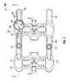
- FIG. 1is a top, plan view of a retractor system in accordance with an embodiment of the present disclosure
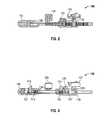
- FIG. 2is a side cross-sectional view of the retractor system of FIG. 1 cut along a section line of 2 - 2 in FIG. 1 ;
- FIG. 3is a side cross-sectional view of the retractor system of FIG. 1 cut along a section line of 3 - 3 in FIG. 1 ;
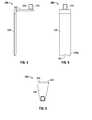
- FIG. 4is a side view of a retractor blade for use with the retractor system of FIG. 1 ;
- FIG. 5is a front view of the retractor blade of FIG. 4 for use with the retractor system of FIG. 1 ;
- FIG. 6is a top, plan view of the retractor blade of FIG. 4 for use with the retractor system of FIG. 1 ;
- FIG. 7is a perspective view of an auxiliary blade for use with the retractor system of FIG. 1 ;
- FIG. 8is a perspective view of an optional table mount for use with the retractor system of FIG. 1 ;
- FIG. 9Ais a side view of a dissector for use with the retractor system of FIG. 1 ;
- FIG. 9Bis a cross-sectional view of the dissector of FIG. 9A ;
- FIG. 9Cis a side view of another dissector for use with the retractor system of FIG. 1 ;
- FIG. 9Dis a side cross-sectional view of the dissector of FIG. 9C ;
- FIG. 9Eis a side view of still another dissector for use with the retractor system of FIG. 1 ;
- FIG. 9Fis a side cross-sectional view of the dissector of FIG. 9E ;
- FIG. 10is a top, plan view of a spinal interbody spacer for use with the retractor system of FIG. 1 ;
- FIG. 11is a side view of the spinal interbody spacer of FIG. 10 ;
- FIG. 12is a cross-sectional view of the spinal interbody spacer of FIG. 10 cut along a section line 12 - 12 in FIG. 11 ;
- FIG. 13Ais a top, plan view of another embodiment of a spinal interbody spacer for use with the retractor system of FIG. 1 ;
- FIG. 13Bis a rear view of the spinal interbody spacer of FIG. 13A ;
- FIG. 14is a perspective view of an inserter for use with the spinal interbody spacer of FIG. 10-12 or 13A-13B ;
- FIG. 15is an exploded perspective view of the inserter of FIG. 14 with parts separated;
- FIG. 16is a perspective view of an intradiscal shim for use with the retractor system of FIG. 1 ;
- FIG. 17is a side view of an intradiscal shim inserter for use with the intradiscal shim of FIG. 16 ;
- FIG. 18is a side view of an intradiscal shim extractor for use with the intradiscal shim of FIG. 16 ;
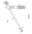
- FIG. 19is a perspective view of a disc spreader for use with the retractor system of FIG. 1 ;
- FIG. 20is a side view of the disc spreader of FIG. 19 ;
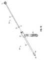
- FIG. 21is a side view of a fixation pin for use with the retractor system of FIG. 1 ;
- FIG. 22is a side view of a fixation pin driver for use with the fixation pin of FIG. 21 ;
- FIG. 23is a side view of a guide wire for use with the retractor system of FIG. 1 ;
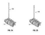
- FIGS. 24 and 25are perspective views of the dissector of FIG. 9A illustrating use thereof;
- FIGS. 26 and 27are perspective views of the dissector of FIG. 24 and a guide wire of FIG. 23 illustrating insertion of the guide wire through the dissector;
- FIG. 28is a perspective view of the guide wire of FIG. 26 illustrating the guide wire inserted in the disc;
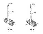
- FIGS. 29 and 30are perspective views of the guide wire of FIG. 28 and the dissector of FIGS. 9C and 9D illustrating insertion of the dissector over the guide wire to enlarge the opening in tissue;
- FIG. 31is a perspective view of the dissector and the guide wire of FIG. 30 illustrating rotation of the dissector to free up soft tissue;
- FIG. 32Ais a perspective view of the retractor system of FIG. 1 including the retractor blades of FIG. 4 attached thereto illustrating insertion of the retractor system over the guide wire;
- FIG. 32Bis a side view of the retractor system of FIG. 32A ;
- FIG. 32Cis a top view of the retractor system of FIG. 32A ;
- FIG. 33is a perspective view of the retractor system of FIG. 32A illustrating the retractor system advanced directly to the spine;
- FIG. 34Ais a perspective view of the retractor system of FIG. 33 illustrating rotation thereof approximately 90 degrees;
- FIG. 34Bis a side view of the retractor system of FIG. 34A ;
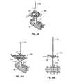
- FIG. 35Ais a perspective view of the retractor system of FIG. 34A illustrating the retractor system retracted to a partially opened position
- FIG. 35Bis a side view of the retractor system of FIG. 35A ;
- FIG. 36Ais a perspective view of the retractor system of FIG. 35A and a fixation pin of FIG. 21 illustrating insertion of the fixation pin into a first vertebra through a longitudinal channel of the retractor blades;
- FIG. 36Bis a side view of the retractor system of FIG. 36A ;
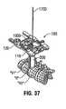
- FIGS. 37 and 38Aare perspective views of the retractor system of FIG. 36A illustrating removal of the guide wire
- FIG. 38Bis a side view of the retractor system of FIG. 38A ;
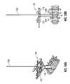
- FIG. 39Ais a perspective view of the retractor system of FIG. 38A in a more fully open position and the fixation pin of FIG. 21 illustrating insertion of the fixation pin into a second vertebra;
- FIG. 39Bis a side view of the retractor system of FIG. 39A ;
- FIG. 40Ais a perspective view of the retractor system of FIG. 39A illustrating the retractor system providing access and visualization of the disc;
- FIG. 40Bis a side view of the retractor system of FIG. 40A .
- distalwill refer to that portion of the instrument, apparatus, device or component thereof which is farther from the user while, the term “proximal,” will refer to that portion of the instrument, apparatus, device or component thereof which is closer to the user.
- proximalwill refer to that portion of the instrument, apparatus, device or component thereof which is closer to the user.
- cephaladis used in this application to indicate a direction toward a patient's head, while the term “caudad” indicates a direction toward the patient's feet.
- the term “medial”indicates a direction toward the middle of the body of the patient
- the term “lateral”indicates a direction toward a side of the body of the patient, i.e., away from the middle of the body of the patient.
- the term “posterior”indicates a direction toward the patient's back
- the term “anterior”indicates a direction toward the patient's front.
- Retractor system 100configured and adapted for a minimally invasive surgical procedure to access, for example, the thoracic or lumbar vertebrae.
- Retractor system 100includes a first support 110 having arms 130 , 132 extending therefrom and a second support 120 that is slidably mounted on arms 130 , 132 .
- Second support 120may be secured in a plurality of locations relative to first support 110 .
- Each support 110 , 120is configured and dimensioned to receive and support a retractor blade 200 ( FIGS. 4-6 ) releasably secured thereto, as will be discussed in detail hereinbelow.
- Second support 120Movement of second support 120 along arms 130 , 132 allows retractor blade 200 on second support 120 to be moved between a position closely adjacent to a blade mounted to support 110 , and a spaced apart position with respect to the opposing retractor blade 200 releasably secured with first support 110 .
- each arm 130 , 132is coupled to first support 110 .
- Arms 130 , 132define respective cavities 133 , 134 that extend at least partially along the length of respective arms 130 , 132 .
- Cavity 133 of arm 130includes a portion having teeth 136 that operatively engage a translation knob 122 of second support 120 .
- Translation knob 122is configured and adapted to secure second support 120 to a particular location on arm 130 upon rotation of translation knob 122 .
- each cavity 133 , 134is configured and dimensioned to accommodate locking wheels 135 , 137 translatably disposed in respective cavities 133 , 134 .
- Each locking wheel 135 , 137is configured and adapted to secure auxiliary blades 400 ( FIG.
- cavity 133is illustrated with teeth to interact with a wheel and ratchet of the second support, alternatively or in addition there could be teeth associated with cavity 134 to engage a ratchet and/or wheel on the other side of secondary support 120 .
- Retractor blade 200is releasably attachable to first support 110 .
- An engaging portion 202 ( FIG. 4 ) of retractor blade 200engages an underside of first support 110 .
- first support 110defines a cavity 119 configured and dimensioned to detachably secure a protruding portion 204 ( FIG. 4 ) of retractor blade 200 therein.
- first support 110includes a locking slider 118 that slidably engages protruding portion 204 of retractor blade 200 to releasably secure protruding portion 204 of retractor blade 200 within cavity 119 .
- Locking slider 118is operatively coupled to a biasing member 115 ( FIG. 3 ) such that locking slider 118 is biased toward a locked state.
- An engaging portion 121 ( FIG. 3 ) of locking slider 118engages a groove 206 ( FIG. 4 ) defined in protruding portion 204 . In this manner, retractor blade 200 is releasably secured to first support 110
- first support 110further defines a pair of recessed portions 112 , 114 aligned with cavities 133 , 134 , respectively.
- Recessed portions 112 , 114are configured and dimensioned to accommodate respective locking wheels 135 , 137 therein to enable approximation of first and second supports 110 , 120 to a close cooperative position with locking wheels 135 , 137 nested in the recessed portions.
- Second support 120includes similar features of first support 110 .
- second support 120defines a cavity 129 configured and dimensioned to receive protruding portion 204 of retractor blade 200 .
- Second support 120also includes a locking slider 128 configured and adapted to releasably secure protruding portion 204 in cavity 129 .
- locking slider 128is operatively coupled to a biasing member 125 ( FIG. 3 ), whereby locking slider 128 is biased toward the engaging state.
- an engaging portion 127FIG.
- retractor blade 200is releasably secured with second support 120 .
- second support 120includes a translation knob 122 rotatably mounted on second support 120 to move second support 120 to a particular position along the length of arms 130 , 132 .
- Translation knob 122engages teeth 136 on arm 130 , whereby rotation of translation knob 122 moves second support 120 to a particular position along arm 130 .
- a ratchetengages the teeth as the second support is moved away from the first support to secure the second support position relative to arms 130 , 132 , and hence also relative to the first support. Rotation of translation knob 122 in the opposite direction with the ratchet released moves the second support 120 along arm 130 in the opposite direction toward the first support.
- second support 120includes a ratchet assembly configured to enable uni-directional movement of second support 120 and lock the second support in position along arms 130 , 132 .
- the ratchet assemblyincludes a ratchet knob 124 that is configured to release/disengage the ratchet assembly with arm 130 to enable selective uni-directional movement of second support 120 .
- retractor blade 200is releasably and interchangeably attachable to first or second supports 110 , 120 , and includes engaging portion 202 and a blade portion 208 extending therefrom.
- Engaging portion 202engages the underside of respective first and second supports 110 , 120 in a superposed relation.
- Blade portion 208is substantially orthogonal to engaging portion 202 , whereby when retractor blade 200 is releasably secured with respective first and second supports 110 , 120 , blade portion 208 is substantially orthogonal to first and second supports 110 , 120 .
- each retractor blade 208may define a predetermined fixed angle with respect to engaging portion 202 and first and second supports 110 , 120 .
- retractor blades 200are attached to first and second supports 110 , 120 , respectively, as shown in FIGS. 32A and 32B .
- the retractor bladehas a thin, substantially flat profile.
- engaging portion 202includes a protruding portion 204 configured and dimensioned to extend through respective cavities 119 , 129 of first and second supports 110 , 120 .
- each protruding portion 204defines a groove 206 configured and dimensioned to securely engage respective engaging portions 121 , 127 ( FIG. 3 ) of locking sliders 118 , 128 of first and second supports 110 , 120 .
- each blade portion 208 of retractor blade 200includes one or more longitudinal channels 209 extending substantially along the length of blade portion 208 .
- opposing channels 209 of blades portions 208define one or more lumens for receiving, for example, a guide wire 1700 ( FIG. 23 ), a guide pin, or other surgical implement therethrough.
- the groovemay be rounded and may have slightly greater than a 180° circumference so that a pin inserted into the groove is held in place, although the pin may be pulled out of the groove with sufficient force.
- a distal end portion 208 a of blade portion 208defines a recess 207 having a concave profile.
- the concave profile of recess 207is adapted to engage and accommodate the contour of a vertebral body.
- the concave recessdefines a radius of curvature in the range of about 0.1 inch to about 1.0 inch, and more preferably about 0.6 inch.
- the concave profile of recess 207improves engagement of retractor blade 200 with the vertebral body (see, for example, FIG. 40A ) and, for example, reduces slippage therewith and tissue creeping under and around the blade, especially as the retractor is manipulated during surgery.
- the surgeonmay be provided with a plurality of retractor blades having various radii of curvatures of concave profile of the recess defined in a distal portion of the blade portion to accommodate various contours of the vertebral body.
- auxiliary blade 400includes an engaging portion 402 defining a cavity 403 of varying dimensions and a blade portion 408 extending from engaging portion 402 .
- Cavity 403 of engaging portion 402is configured and dimensioned to be secured along the length of arms 130 , 132 .
- cavity 403defines an enlarged portion 404 and a narrowed portion 406 .
- enlarged portion 404 of cavity 403is dimensioned to receive therethrough locking wheel 135 , 137 such that engaging portion 402 of auxiliary blade 400 may be positioned on arms 130 , 132 in a superposed relation and secured by locking wheels 135 , 137 .
- a neck portion 136 ( FIG. 3 ) of locking wheel 135 , 137is configured and dimensioned to be slidably received in narrowed portion 406 of auxiliary blade 400 .
- Blade portion 408is substantially orthogonal with respect to engaging portion 402 , whereby when auxiliary blade 400 is secured with respective arms 130 , 132 , blade portion 408 is substantially orthogonal to arms 130 , 132 .
- each blade portion 408includes one or more longitudinal channels 409 extending substantially along the length of blade portion 408 .
- Channels 409are configured and dimensioned to receive, for example, guide wire 1700 , a guide pin, or other surgical implement such as an intradiscal shim 1300 ( FIG. 16 ), as discussed below.
- auxiliary blade 400may be adjustably secured to arms 130 , 132 .
- neck portion 136 of locking wheel 135may be slidably received through narrowed portion 406 of cavity 403 to enable the surgeon to select a particular position of auxiliary blade 400 in the transverse direction, as well as the longitudinal direction on arms 130 , 132 .
- the surgeonmay rotate locking wheel 135 , 137 in a first direction to secure auxiliary blade 400 to arm 130 , 132 .
- the surgeonmay rotate locking wheel 135 , 137 in a direction opposite the first to release auxiliary blade 400 from arm 130 , 132 .
- each dissector 500 , 600 , 700has a central passage 505 , 605 , 705 extending along its length with open proximal and distal ends.
- Central passage 505 , 605 , 705is configured and dimensioned such that dissector 500 , 600 , 700 may slidably receive guide wire 1700 ( FIG. 23 ) or guide pin therethrough.
- Guide wire 1700 or guide pinmay guide dissector 500 , 600 , 700 to slide therealong, as will be described below.
- each dissector 500 , 600 , 700has indicia indicating depth of the body cavity or the distance between the epidermal tissue surface and the vertebral body. The surgeon may utilize such indicia to select an appropriate retractor blade.
- central passage 505 , 605 , 705is defined by an electrically conductive tube with plastic over molded onto and surrounding the tube.
- a notch 610 , 710is formed in the proximal portion of dissector 600 , 700 to expose a portion of the tube should a surgeon desire to use dissector 600 , 700 in association with an electromyography system in a known manner.
- a clip from the electromyography systemcan be contacted with the conductive tube at the proximal notch, with the signal transmitted along the tube inside the insulating plastic outer body, to the distal tip of the conductive tube which contacts tissue.
- Spacer 900for use with retractor system 100 for placement between vertebrae.
- Spacer 900includes a pair of opposing sidewalls 960 , 962 , a blunt nose 970 , and an arcuate proximal wall 926 .
- Spacer 900is monolithically formed and is made of any suitable biocompatible material such as polyetheretherketone (PEEK), polysulfone (RADEL), polyetherimide (ULTEM), stainless steel, cobalt chrome, titanium, and titanium alloys.
- PEEKpolyetheretherketone
- RADELpolysulfone
- ULTEMpolyetherimide
- stainless steelcobalt chrome, titanium, and titanium alloys.
- Interbody spacer 900defines a generally torpedo-shaped profile with an opening 928 extending therethrough to permit bone growth between adjacent vertebrae.
- opening 928may contain additional bone graft material.
- Blunt nose 970includes substantially contoured, tapered surface to facilitate insertion thereof between the vertebral bodies.
- Spacer 900includes vertebral body engaging top and bottom surfaces 922 , 924 having protrusions configured to facilitate gripping and securing of spacer 900 with adjacent vertebra.
- the protrusionincludes ring-patterned protrusions 944 concentrically arranged with respect to opening 928 .
- ring-patterned protrusions 944 of opposing top and bottom surfaces 922 , 924may be configured to enable secure engagement with respect to each other when disposed in a superposed relation.
- arcuate proximal wall 926includes a recess 930 defining a threaded aperture 935 for mating with an insertion tool 50 ( FIG. 14 ).
- Top and bottom surfaces 922 , 924 of spacer 900are substantially parallel to one another.
- top and bottom surfaces 1922 , 1924 of spacer 1900may contain lordosis and are not substantially parallel ( FIGS. 13A and 13B ).
- spacer 900may be tapered laterally defining a generally wedge shaped configuration.
- one sidewallmay have a height that is different from the height of the opposing sidewall defining the tapered or lordotic configuration.
- the opposing sidewallsmay have the same height, and thus defining a parallel configuration.
- Insertion tool 50may be utilized to insert spacer 900 between vertebral bodies.
- Insertion tool 50includes a housing 52 having a tubular member 53 extending therefrom.
- a handle 54extends from housing 52 and is orthogonal to tubular member 53 .
- a coupling 55is disposed at a distal end 51 of tubular member 53 and is configured and adapted for mating with arcuate proximal wall 926 of spacer 900 .
- a lumen 56extends from distal end 51 of coupling 55 to a proximal end 57 of housing 52 .
- Inserter rod 70is repositionable through housing 52 and tubular member 53 .
- Inserter rod 70has a threaded portion 72 at its distal end 71 that is configured for threadably engaging threaded aperture 935 of spacer 900 .
- a knob 74is disposed in opposition to threaded portion 72 with a shaft 75 extending therebetween.
- a table mounted surgical arm(not shown) may be attached to the frame with the use of a stabilization arm adapter 1600 ( FIG. 8 ).
- illumination structuresuch as fiber optics, LED, may be utilized with retractor blade 200 to assist in visualization.
- a portion of blade portion 208 of retractor blade 200may be clear plastic and act as light channels themselves.
- the clinicianpositions the patient in a lateral decubitus position on an operating table having a table break such that the patient's iliac crest is directly over the table break.
- the patientmay be secured in position using tape at several locations while avoiding undue pressure points.
- the clinicianuses fluoroscopy or another imaging modality to identify the correct operative level and makes one or more incisions through the patient's skin using conventional instruments. The number and type of incisions made (e.g. transverse or vertical) is related to the procedure to be performed.
- the subcutaneous tissue layersare taken down exposing the oblique fascia.
- the muscle fibersare carefully separated as a finger is advanced into the retroperitoneal space.
- the peritoneumis safely released anteriorly as the retroperitoneal space is further developed. Finger palpation of the psoas muscle or the anterior tip of the transverse process is used to confirm proper location.
- dissector 500( FIG. 9A ) is introduced into the prepared path and advanced through the psoas muscle, as shown in FIG. 24 .
- dissector 500is docked directly into the middle of disc “d,” as shown in FIG. 25 .
- guide wire 1700( FIG. 23 ) is inserted through dissector 500 into disc “d,’ as shown in FIGS. 26 and 27 .
- Dissector 500is removed, leaving guide wire 1700 in place, as shown in FIG. 28 .
- One or more larger dissectors 600 , 700may be introduced over guide wire 1700 to enlarge the opening, as shown in FIG. 30 .
- the clinicianmay use, for example, a slight windshield wiper motion, anterior to posterior, to free up soft tissue.
- the clinicianmanipulates dissector 600 along the line of the muscle fibers of the psoas, to thereby minimize trauma, as seen in FIG. 31 .
- dissectors 600 , 700are wider in one direction that the other (see FIG. 9E ), which facilitates insertion of the dissector between fibers of the psoas muscle with the dissector oriented such that wider profile is aligned with the fibers and the thinner profile is oriented transverse to the psoas muscle fibers.
- the surgeonmay connect an electromyography system to one or more of the dissectors to monitor nerve activity during insertion and movement of the dissector.
- blade lengthmay be determined by any one of the dissectors 500 , 600 , 700 in relation to skin level.
- the clinicianmay readily determine an appropriate blade length for retractor system 100 by reading the indicia shown on dissector 500 , 600 , 700 .
- the clinicianprepares retractor system 100 for use by selecting retractor blades with the desired length and releasably attaching a pair of retractor blades 200 to the first and second support 110 , 120 of the retractor system 100 .
- Second support 120is translated along the arms 130 , 132 towards first support 110 such that retractor blades 200 are in close cooperative alignment, as shown in FIG. 32A .
- the clinicianthen removes dissector 600 , 700 and inserts retractor system 100 with the closed retractor blades 200 into the prepared opening and along the longitudinal axis of the psoas muscle fibers.
- the retractormay be inserted over guide wire 1700 with guide wire 1700 extending through a lumen defined by longitudinal channel 209 .
- Retractor system 100is kept in line with the muscle fibers and advanced directly to the spine until the distal tips of the blades are adjacent the spine, as shown in FIG. 33 .
- the low profile of the closed retractor bladespermits the blades to be worked between the fibers of the psoas muscle until the distal tips of the blades pass through the psoas muscle and may be positioned adjacent the vertebrae.
- Retractor system 100is then turned approximately 90° so that the orientation of retractor blades 200 is in line with the endplates of the vertebrae, as shown in FIGS. 34A and 34B .
- retractor system 100is moved or retracted partially open so that the superior retractor blade is disposed over the adjacent vertebral body, as shown in FIGS. 35A and 35B .
- one or more fixation pins 1000may be introduced through one or more of channels 209 of retractor blade 200 and advanced into vertebra “V 1 ” using a fixation pin driver 1200 ( FIG. 22 ), as shown in FIGS. 36A and 36B .
- fixation pin 1000has a threaded distal portion 1020 for fixedly engaging bone structures and a head 1040 that is operatively coupled to fixation pin driver 1200 for inserting or removing fixation pin 1000 .
- knob 122With the superior blade affixed to the superior vertebra “V 1 ,” knob 122 is actuated to move first support 110 away from second support 120 , as shown in FIG. 37 .
- first support 110 affixed to the superior vertebra “V 1 ”knob 122 may be actuated to move second support 120 from first support 110 .
- a slidable crank arm 123( FIG. 1 ) may be extended outward from the knob 122 for additional cranking leverage.
- auxiliary blades 400for lateral aspect of retractor system 100 may be used. In particular, auxiliary blades 400 are inserted into the incision, drawn back along arms 130 , 132 and locked into place by rotating locking wheel 135 , 137 .
- Fixation pins 1000assist in securing blades 200 to the vertebra to hold the distal blade tips in position against the vertebral bodies “V 1 ,” “V 2 ” to assure that retracted tissue does not slip under blades 200 into the operative field as retractor system 100 is leveraged and manipulated during surgery.
- An intradiscal shim 1300may also be used to ensure minimal soft tissue creep during instrumentation.
- Intradiscal shim 1300is introduced into channel 409 of auxiliary blade 400 and may be advanced directly into the disc space using a shim inserter tool 1400 ( FIG. 17 ).
- Intradiscal shim 1300is removed using an extractor tool 1450 ( FIG. 18 ).
- an optional table mount arm 1600( FIG. 8 ) is attached to retractor system 100 and coupled to an external support (not shown). Once the desired access is achieved, traditional annulotomy and discectomy are performed as well as the release of the contralateral annulus.
- a selection of disc preparation instrumentsincluding a variety of curettes, ronguers, rasps, chisels, and cobbs may also be used.
- a disc spreader 1500( FIGS. 19 and 20 ) having a flattened blade portion 1520 at a distal end 1510 thereof may be used to adequately distract the disc space. Blade portion 1520 may also include a plurality of markings 1530 that indicate a distance from a distal end 1550 of blade portion 1520 .
- Implant 900is to be inserted into the intervertebral space, a series of trial implants (not shown) may be used prior to deploying spinal interbody spacer 900 .
- Trial implantsmay be configured in both lordotic and parallel versions.
- interbody spacer 900is inserted using implant insertion tool 50 .
- the inserter rod 70 and handle 54are coupled together and the selected spinal interbody spacer 900 is threaded on distal end 71 of inserter rod 70 adjacent coupling 55 of distal end 51 of tubular member 53 .
- a mallet and slap hammer(not shown) may also be used to facilitate placement of interbody spacer 900 .
- ratchet release arm 124is actuated to permit second support 120 to reapproximate towards first support 110 , and retractor system 100 is removed from the incision, which may be closed in a traditional manner.
- fixation pins 1000may be used at any point during the procedure or they may not be used at all during the procedure. It will be understood that various modifications may be made to the embodiments of the presently disclosed lateral access system.
- the spacercan be inserted over a rail system such as that shown in U.S. Pat. No. 7,615,079 to Flickinger et al., the contents of which are incorporated by reference herein in their entirety. It is further contemplated that the spacer can be assembled in situ over rails on both sides of the inserter with the tip of the inserter becoming a part of the implant as shown in U.S.
Landscapes
- Health & Medical Sciences (AREA)
- Life Sciences & Earth Sciences (AREA)
- Engineering & Computer Science (AREA)
- Biomedical Technology (AREA)
- Surgery (AREA)
- Heart & Thoracic Surgery (AREA)
- Veterinary Medicine (AREA)
- Public Health (AREA)
- General Health & Medical Sciences (AREA)
- Animal Behavior & Ethology (AREA)
- Orthopedic Medicine & Surgery (AREA)
- Medical Informatics (AREA)
- Molecular Biology (AREA)
- Nuclear Medicine, Radiotherapy & Molecular Imaging (AREA)
- Neurology (AREA)
- Transplantation (AREA)
- Vascular Medicine (AREA)
- Oral & Maxillofacial Surgery (AREA)
- Cardiology (AREA)
- Pathology (AREA)
- Biophysics (AREA)
- Optics & Photonics (AREA)
- Physics & Mathematics (AREA)
- Radiology & Medical Imaging (AREA)
- Physical Education & Sports Medicine (AREA)
- Surgical Instruments (AREA)
- Prostheses (AREA)
Abstract
Description
Claims (17)
Priority Applications (1)
| Application Number | Priority Date | Filing Date | Title |
|---|---|---|---|
| US14/958,123US9782158B2 (en) | 2010-10-08 | 2015-12-03 | Lateral access system and method of use |
Applications Claiming Priority (4)
| Application Number | Priority Date | Filing Date | Title |
|---|---|---|---|
| US39140210P | 2010-10-08 | 2010-10-08 | |
| US13/270,588US8449463B2 (en) | 2010-10-08 | 2011-10-11 | Lateral access system and method of use |
| US13/871,657US9220491B2 (en) | 2010-10-08 | 2013-04-26 | Lateral access system and method of use |
| US14/958,123US9782158B2 (en) | 2010-10-08 | 2015-12-03 | Lateral access system and method of use |
Related Parent Applications (1)
| Application Number | Title | Priority Date | Filing Date |
|---|---|---|---|
| US13/871,657ContinuationUS9220491B2 (en) | 2010-10-08 | 2013-04-26 | Lateral access system and method of use |
Publications (2)
| Publication Number | Publication Date |
|---|---|
| US20160081684A1 US20160081684A1 (en) | 2016-03-24 |
| US9782158B2true US9782158B2 (en) | 2017-10-10 |
Family
ID=45925658
Family Applications (5)
| Application Number | Title | Priority Date | Filing Date |
|---|---|---|---|
| US13/270,588Active2032-01-02US8449463B2 (en) | 2010-10-08 | 2011-10-11 | Lateral access system and method of use |
| US13/856,574Active2032-06-15US9192367B2 (en) | 2010-10-08 | 2013-04-04 | Lateral access system and method of use |
| US13/856,564Active2032-06-18US9186132B2 (en) | 2010-10-08 | 2013-04-04 | Lateral access system and method of use |
| US13/871,657Active2032-09-03US9220491B2 (en) | 2010-10-08 | 2013-04-26 | Lateral access system and method of use |
| US14/958,123Active2032-02-13US9782158B2 (en) | 2010-10-08 | 2015-12-03 | Lateral access system and method of use |
Family Applications Before (4)
| Application Number | Title | Priority Date | Filing Date |
|---|---|---|---|
| US13/270,588Active2032-01-02US8449463B2 (en) | 2010-10-08 | 2011-10-11 | Lateral access system and method of use |
| US13/856,574Active2032-06-15US9192367B2 (en) | 2010-10-08 | 2013-04-04 | Lateral access system and method of use |
| US13/856,564Active2032-06-18US9186132B2 (en) | 2010-10-08 | 2013-04-04 | Lateral access system and method of use |
| US13/871,657Active2032-09-03US9220491B2 (en) | 2010-10-08 | 2013-04-26 | Lateral access system and method of use |
Country Status (5)
| Country | Link |
|---|---|
| US (5) | US8449463B2 (en) |
| EP (1) | EP2624767B1 (en) |
| JP (1) | JP6045497B2 (en) |
| AU (1) | AU2011312111B2 (en) |
| WO (1) | WO2012048337A1 (en) |
Cited By (14)
| Publication number | Priority date | Publication date | Assignee | Title |
|---|---|---|---|---|
| US10405842B2 (en) | 2016-09-26 | 2019-09-10 | K2M, Inc. | Retraction system and method of use |
| US10687797B2 (en) | 2008-12-18 | 2020-06-23 | Howmedica Osteonics Corp. | Lateral access system for the lumbar spine |
| US10898174B2 (en) | 2013-03-11 | 2021-01-26 | Spinal Elements, Inc. | Method of using a surgical tissue retractor |
| US10973505B2 (en) | 2016-03-09 | 2021-04-13 | Spinal Elements, Inc. | Retractor |
| US11166709B2 (en) | 2016-08-23 | 2021-11-09 | Stryker European Operations Holdings Llc | Instrumentation and methods for the implantation of spinal implants |
| US11179146B2 (en) | 2014-09-10 | 2021-11-23 | Spinal Elements, Inc. | Retractor |
| US11191532B2 (en) | 2018-03-30 | 2021-12-07 | Stryker European Operations Holdings Llc | Lateral access retractor and core insertion |
| USD956225S1 (en) | 2020-05-12 | 2022-06-28 | Innovasis, Inc. | Surgical retractor |
| USD956224S1 (en) | 2020-05-12 | 2022-06-28 | Innovasis, Inc. | Surgical retractor |
| USD956223S1 (en) | 2020-05-12 | 2022-06-28 | Innovasis, Inc. | Surgical retractor |
| US11413029B2 (en) | 2018-10-24 | 2022-08-16 | Stryker European Operations Holdings Llc | Anterior to psoas instrumentation |
| US11432810B2 (en) | 2020-05-12 | 2022-09-06 | Innovasis, Inc. | Systems and methods for surgical retraction |
| US11564674B2 (en) | 2019-11-27 | 2023-01-31 | K2M, Inc. | Lateral access system and method of use |
| US12343001B2 (en) | 2021-06-11 | 2025-07-01 | Corelink, Llc | Tissue retractor and adaptor therefor |
Families Citing this family (53)
| Publication number | Priority date | Publication date | Assignee | Title |
|---|---|---|---|---|
| US9795367B1 (en) | 2003-10-17 | 2017-10-24 | Nuvasive, Inc. | Surgical access system and related methods |
| EP2531127A4 (en)* | 2009-11-11 | 2015-04-29 | Alphatec Spine Inc | METHODS AND DEVICES FOR FIXING A PENETRATION POINT ON THE VERTEBRAL COLUMN |
| CN109171845B (en) | 2010-08-23 | 2021-04-13 | 纽文思公司 | Retractor Assembly |
| US8449463B2 (en) | 2010-10-08 | 2013-05-28 | K2M, Inc. | Lateral access system and method of use |
| CN103987326B (en) | 2011-08-19 | 2016-06-08 | 诺威适有限公司 | Surgical retractor system and method of use |
| US9113853B1 (en) | 2011-08-31 | 2015-08-25 | Nuvasive, Inc. | Systems and methods for performing spine surgery |
| US20140058446A1 (en)* | 2011-09-28 | 2014-02-27 | Avi Bernstein | Spinal implant system |
| US9622779B2 (en)* | 2011-10-27 | 2017-04-18 | DePuy Synthes Products, Inc. | Method and devices for a sub-splenius / supra-levator scapulae surgical access technique |
| US9463052B2 (en) | 2012-01-12 | 2016-10-11 | Integrity Implants Inc. | Access assembly for anterior and lateral spinal procedures |
| US9066701B1 (en) | 2012-02-06 | 2015-06-30 | Nuvasive, Inc. | Systems and methods for performing neurophysiologic monitoring during spine surgery |
| US9655505B1 (en) | 2012-02-06 | 2017-05-23 | Nuvasive, Inc. | Systems and methods for performing neurophysiologic monitoring during spine surgery |
| US9757067B1 (en) | 2012-11-09 | 2017-09-12 | Nuvasive, Inc. | Systems and methods for performing neurophysiologic monitoring during spine surgery |
| US9095385B2 (en)* | 2012-11-21 | 2015-08-04 | K2M, Inc. | Adjustable spinal implant insertion instrument |
| EP3164080A4 (en) | 2014-07-06 | 2018-06-27 | Garcia-Bengochea, Javier | Methods and devices for surgical access |
| WO2017008087A1 (en) | 2015-07-06 | 2017-01-12 | Javier Garcia-Bengochea | Methods and devices for surgical access |
| US10194896B2 (en)* | 2014-11-03 | 2019-02-05 | Archer Medical, Inc. | Surgical retractor system and method |
| US20160213405A1 (en) | 2015-01-27 | 2016-07-28 | K2M, Inc. | Vertebral plate systems and methods of use |
| US10028841B2 (en) | 2015-01-27 | 2018-07-24 | K2M, Inc. | Interbody spacer |
| KR101760730B1 (en)* | 2015-03-10 | 2017-07-24 | 주식회사 메드릭스 | Rail type retractor for minimal invasive surgery |
| US20180049754A1 (en)* | 2015-03-13 | 2018-02-22 | Redemed S.R.L. | Intervertebral prosthesis, apparatus for implanting intervertebral prostheses and surgical method for implanting intervertebral prostheses, particularly for percutaneous mini-invasive surgery procedures |
| WO2016160397A1 (en)* | 2015-04-03 | 2016-10-06 | Tedan Surgical Innovations, LLC. | Retractor blade assembly |
| US9848862B2 (en) | 2015-04-03 | 2017-12-26 | Tedan Surgical Innovations, LLC. | Retractor blade assembly |
| US9408598B1 (en) | 2015-05-18 | 2016-08-09 | Altus Partners, Llc | Systems and methods for accessing an intervertebral disc space in a body of a patient |
| US10201342B2 (en)* | 2015-06-01 | 2019-02-12 | Alphatec Spine, Inc. | Radio transparent retractor system and method of using radio transparent retractor system |
| US10499894B2 (en) | 2015-08-12 | 2019-12-10 | K2M, Inc. | Orthopedic surgical system including surgical access systems, distraction systems, and methods of using same |
| US10149674B2 (en) | 2015-08-12 | 2018-12-11 | K2M, Inc. | Orthopedic surgical system including surgical access systems, distraction systems, and methods of using same |
| US10058350B2 (en) | 2015-09-24 | 2018-08-28 | Integrity Implants, Inc. | Access assembly for anterior and lateral spinal procedures |
| US10420591B2 (en)* | 2016-04-14 | 2019-09-24 | Spinal Simplicity, Llc | Interspinous implant insertion instrument with staggered path implant deployment mechanism |
| WO2017184712A1 (en)* | 2016-04-19 | 2017-10-26 | Worcester Polytechnic Institute | Surgical retraction device |
| US10084903B2 (en)* | 2016-07-07 | 2018-09-25 | Conduent Business Services, Llc | Method and system for establishing a communication channel between computing devices in a customer care environment |
| US20180206834A1 (en)* | 2017-01-04 | 2018-07-26 | MIS IP Holdings, LLC | System for Approaching the Spine Laterally and Retracting Tissue in an Anterior to Posterior Direction |
| DE102017106846A1 (en)* | 2017-03-30 | 2018-10-04 | Aesculap Ag | Surgical retractor system comprising a retractor and an extractor, and a torsional surgical instrument |
| CN110831548B (en)* | 2017-05-22 | 2022-07-22 | 公理医学有限公司 | System and method for performing a disc replacement procedure through a lateral approach |
| US10952714B1 (en) | 2017-07-14 | 2021-03-23 | OrtoWay AB | Apparatus, methods and systems for spine surgery |
| US11051857B2 (en) | 2017-08-10 | 2021-07-06 | Ortho Development Corporation | Tether clamping assemblies and related methods and apparatus |
| US11071569B2 (en) | 2017-08-10 | 2021-07-27 | Ortho Development Corporation | Nesting tether clamping assemblies and related methods and apparatus |
| WO2019036048A2 (en) | 2017-08-17 | 2019-02-21 | Stryker European Holdings I, Llc | Lateral access bridges, shims and lighting including rod lighting |
| US11013616B2 (en) | 2018-10-10 | 2021-05-25 | K2M, Inc. | Sagittal balance systems and methods of use thereof |
| USD882780S1 (en)* | 2019-01-11 | 2020-04-28 | Edward Rustamzadeh | Surgical spinal dilator |
| US11426152B2 (en)* | 2019-01-30 | 2022-08-30 | Spine Wave, Inc. | Multilevel lateral access system |
| US11266391B2 (en) | 2019-02-11 | 2022-03-08 | Warsaw Orthopedic, Inc. | Surgical retractor and method |
| US10631842B1 (en)* | 2019-02-12 | 2020-04-28 | Edward Rustamzadeh | Lateral retraction system for minimizing muscle damage in spinal surgery |
| US12016543B2 (en) | 2019-02-12 | 2024-06-25 | Edward Rustamzadeh | Lateral retractor system for minimizing muscle damage in spinal surgery |
| US10363023B1 (en) | 2019-02-12 | 2019-07-30 | Edward Rustamzadeh | Lateral retractor system for minimizing muscle damage in spinal surgery |
| US10925593B2 (en) | 2019-02-12 | 2021-02-23 | Edward Rustamzadeh | Lateral retractor system for minimizing muscle damage in spinal surgery |
| US11246582B2 (en) | 2019-02-12 | 2022-02-15 | Edward Rustamzadeh | Dual-motion rotation and retraction system for minimizing muscle damage in spinal surgery |
| US11793558B2 (en) | 2019-08-30 | 2023-10-24 | K2M, Inc. | All in one plate holder and spring loaded awl |
| US11819255B2 (en) | 2019-10-07 | 2023-11-21 | Ortho Development Corporation | Tether tensioning instrumentation and related methods |
| US11311282B1 (en) | 2020-10-15 | 2022-04-26 | Charles R. Watts | Cervical retractor and method |
| USD1002842S1 (en) | 2021-06-29 | 2023-10-24 | Edward Rustamzadeh | Combination surgical spinal dilator and retractor system |
| US11457910B1 (en) | 2021-07-30 | 2022-10-04 | Nuvasive, Inc. | Surgical shim |
| US12295624B2 (en)* | 2022-05-24 | 2025-05-13 | Globus Medical, Inc. | TLIF distraction and retraction |
| WO2024074925A1 (en) | 2022-10-07 | 2024-04-11 | Neo Medical Sa | Retractor system for spine surgery |
Citations (33)
| Publication number | Priority date | Publication date | Assignee | Title |
|---|---|---|---|---|
| US3749088A (en)* | 1971-06-23 | 1973-07-31 | W Kohlmann | Surgical retractor device |
| US5484437A (en) | 1988-06-13 | 1996-01-16 | Michelson; Gary K. | Apparatus and method of inserting spinal implants |
| US5728046A (en)* | 1995-06-23 | 1998-03-17 | Aesculap Ag | Surgical retractor |
| US5813978A (en) | 1994-07-19 | 1998-09-29 | Atlantis Surgical, Inc. | Method and apparatus for direct access endoscopic surgery |
| US5928139A (en)* | 1998-04-24 | 1999-07-27 | Koros; Tibor B. | Retractor with adjustable length blades and light pipe guides |
| US5944658A (en) | 1997-09-23 | 1999-08-31 | Koros; Tibor B. | Lumbar spinal fusion retractor and distractor system |
| US20010049527A1 (en) | 2000-02-16 | 2001-12-06 | Cragg Andrew H. | Methods and apparatus for performing therapeutic procedures in the spine |
| US6436119B1 (en) | 1999-09-30 | 2002-08-20 | Raymedica, Inc. | Adjustable surgical dilator |
| US20030149341A1 (en) | 2002-02-06 | 2003-08-07 | Clifton Guy L. | Retractor and/or distractor for anterior cervical fusion |
| US20040010312A1 (en) | 2002-07-09 | 2004-01-15 | Albert Enayati | Intervertebral prosthesis |
| US6716218B2 (en) | 2001-02-28 | 2004-04-06 | Hol-Med Corporation | Instrument for bone distraction and compression having ratcheting tips |
| US20040230191A1 (en) | 2002-11-23 | 2004-11-18 | George Frey | Distraction and retraction system for spinal surgery |
| US20050149035A1 (en) | 2003-10-17 | 2005-07-07 | Nuvasive, Inc. | Surgical access system and related methods |
| US20050216088A1 (en) | 1998-05-27 | 2005-09-29 | Nu Vasive, Inc. | Bone blocks and methods for inserting bone blocks into intervertebral spaces |
| EP1611851A1 (en) | 2004-06-30 | 2006-01-04 | Thompson Surgical Instruments, Inc. | Elongateable surgical port and dilator |
| US20060084844A1 (en) | 2004-10-19 | 2006-04-20 | Nehls Daniel G | Retractor and distractor system for use in anterior cervical disc surgery |
| US20060247645A1 (en) | 2005-04-29 | 2006-11-02 | Wilcox Bryan S | Orthopedic instrument |
| US20060287730A1 (en) | 2005-06-15 | 2006-12-21 | Jerome Segal | Mechanical apparatus and method for artificial disc replacement |
| US20080021284A1 (en) | 2006-07-19 | 2008-01-24 | Zimmer Spine, Inc. | Surgical access system and method of using the same |
| US20080183046A1 (en) | 2007-01-26 | 2008-07-31 | Wayne Boucher | Surgical retractor with removable blades and method of use |
| US20080262501A1 (en) | 2007-04-20 | 2008-10-23 | Richard Evan Chen | Multi-function corpectomy instrument |
| US20090036746A1 (en) | 2007-08-01 | 2009-02-05 | Jonathan Blackwell | Instrumentation for tissue retraction |
| US20090228110A1 (en) | 2008-03-07 | 2009-09-10 | K2M, Inc. | Intervertebral instrument, implant, and method |
| US7615079B2 (en) | 2006-04-20 | 2009-11-10 | Meditech Advisors, Llc | Monorail system |
| US7666201B2 (en) | 1999-09-08 | 2010-02-23 | Jeffrey Grayzel | Spreading instrument |
| US20100174146A1 (en) | 2002-10-08 | 2010-07-08 | Patrick Miles | Surgical access system and related methods |
| WO2010114625A2 (en) | 2009-04-03 | 2010-10-07 | Hardenbrook Mitchell A | Surgical retractor system |
| US7846093B2 (en) | 2005-09-26 | 2010-12-07 | K2M, Inc. | Minimally invasive retractor and methods of use |
| US20110034777A1 (en)* | 2009-04-13 | 2011-02-10 | Lanx, Inc. | Expandable retractor and methods incorporating the same |
| US8241294B2 (en) | 2007-12-19 | 2012-08-14 | Depuy Spine, Inc. | Instruments for expandable corpectomy spinal fusion cage |
| US8377070B2 (en) | 2007-05-17 | 2013-02-19 | Michael T. Gauthier | Compressor distractor tool |
| US8449463B2 (en) | 2010-10-08 | 2013-05-28 | K2M, Inc. | Lateral access system and method of use |
| US8636657B2 (en) | 2002-10-25 | 2014-01-28 | K2M, Inc. | Minimal incision maximal access MIS spine instrumentation and method |
Family Cites Families (39)
| Publication number | Priority date | Publication date | Assignee | Title |
|---|---|---|---|---|
| US2450194A (en)* | 1946-07-22 | 1948-09-28 | Glaser Mark Albert | Adjustable retractor |
| US4747394A (en)* | 1986-10-08 | 1988-05-31 | Watanabe Orthopedic Systems, Inc. | Spinal retractor |
| US5299357A (en)* | 1991-12-18 | 1994-04-05 | American Safety Razor Company | Disposable surgical scalpel with safety guard |
| US5324290A (en)* | 1992-09-24 | 1994-06-28 | Danek Medical, Inc. | Anterior thoracolumbar plate |
| US5772583A (en)* | 1994-01-21 | 1998-06-30 | Wright; John T. M. | Sternal retractor with attachments for mitral & tricuspid valve repair |
| US5795291A (en)* | 1994-11-10 | 1998-08-18 | Koros; Tibor | Cervical retractor system |
| US5616117A (en)* | 1995-08-03 | 1997-04-01 | Ohio Medical Instrument Company, Inc. | Self locking surgical retractor |
| US5846193A (en)* | 1997-05-01 | 1998-12-08 | Wright; John T. M. | Midcab retractor |
| US5779629A (en)* | 1997-10-02 | 1998-07-14 | Hohlen; Robert D. | Dual axis retractor |
| US6224545B1 (en)* | 1998-07-24 | 2001-05-01 | Core Surgical, Inc. | Surgical retractor and method for use |
| US6042542A (en)* | 1998-11-10 | 2000-03-28 | Koros; Tibor B. | Rotatable retractor blade with detachable clamp |
| US6206828B1 (en)* | 1999-06-08 | 2001-03-27 | John T. M. Wright | Sternal retractor with changeable blades and blade latch mechanism |
| US6464634B1 (en)* | 2000-09-27 | 2002-10-15 | Depuy Acromed, Inc. | Surgical retractor system |
| US7011658B2 (en)* | 2002-03-04 | 2006-03-14 | Sdgi Holdings, Inc. | Devices and methods for spinal compression and distraction |
| US7261688B2 (en)* | 2002-04-05 | 2007-08-28 | Warsaw Orthopedic, Inc. | Devices and methods for percutaneous tissue retraction and surgery |
| US6712795B1 (en)* | 2002-06-07 | 2004-03-30 | Lester Cohen | Surgical procedure and apparatus |
| US6945933B2 (en)* | 2002-06-26 | 2005-09-20 | Sdgi Holdings, Inc. | Instruments and methods for minimally invasive tissue retraction and surgery |
| US7147599B2 (en)* | 2002-07-03 | 2006-12-12 | Boss Instruments, Ltd., Inc. | Surgical retractor with improved arms |
| EP1558184A2 (en)* | 2002-10-08 | 2005-08-03 | SDGI Holdings, Inc. | Insertion device and techniques for orthopaedic implants |
| JP4463819B2 (en)* | 2003-09-25 | 2010-05-19 | ヌヴァシヴ インコーポレイテッド | Surgical access system |
| US20050137461A1 (en)* | 2003-12-18 | 2005-06-23 | Depuy Spine, Inc. | Telescoping blade assembly and instruments for adjusting an adjustable blade |
| US7150714B2 (en)* | 2004-06-14 | 2006-12-19 | Ebi, L.P. | Minimally invasive surgical spinal exposure system |
| US7556600B2 (en)* | 2004-09-09 | 2009-07-07 | Zimmer Spine, Inc. | Surgical retraction apparatus and associated methods |
| US20070050028A1 (en)* | 2005-08-26 | 2007-03-01 | Conner E S | Spinal implants and methods of providing dynamic stability to the spine |
| US7569014B2 (en)* | 2005-09-07 | 2009-08-04 | West Coast Surgical, Llc | Connector for a surgical retractor |
| US7588537B2 (en)* | 2005-09-07 | 2009-09-15 | West Coast Surgical, Llc. | Connector with safety latch for a surgical retractor |
| US7537565B2 (en)* | 2005-09-27 | 2009-05-26 | Daniel Bass | Surgical retractor with rotating blades |
| US7918792B2 (en)* | 2006-01-04 | 2011-04-05 | Depuy Spine, Inc. | Surgical retractor for use with minimally invasive spinal stabilization systems and methods of minimally invasive surgery |
| US7985179B2 (en)* | 2006-01-23 | 2011-07-26 | Pioneer Surgical Technology | Retraction apparatus and method of use |
| US7922658B2 (en)* | 2006-11-09 | 2011-04-12 | Ebi, Llc | Surgical retractor device and related methods |
| ES2279733B1 (en)* | 2006-11-27 | 2008-08-16 | Rudolf Morgenstern Lopez | DEVICE FOR ELIMINATION OF FABRIC IN ENDOSCOPIC OPERATIONS. |
| US8202216B2 (en)* | 2007-03-08 | 2012-06-19 | Warsaw Orthopedic, Inc. | Tissue retractor |
| US8709054B2 (en)* | 2007-08-07 | 2014-04-29 | Transcorp, Inc. | Implantable vertebral frame systems and related methods for spinal repair |
| US9060757B2 (en)* | 2008-05-05 | 2015-06-23 | Ranier Limited | Distractor |
| US8262570B2 (en)* | 2008-05-30 | 2012-09-11 | Pioneer Surgical Technology, Inc. | Retraction apparatus and method of use |
| US8968192B2 (en)* | 2008-06-06 | 2015-03-03 | Warsaw Orthopedic, Inc. | Systems and methods for tissue retraction |
| US8226554B2 (en)* | 2008-10-30 | 2012-07-24 | Warsaw Orthopedic, Inc. | Retractor assemblies for surgery in a patient |
| US20110098537A1 (en)* | 2009-10-28 | 2011-04-28 | Warsaw Orthopedic, Inc. | Tissue massage retractor |
| US9131935B2 (en)* | 2010-10-01 | 2015-09-15 | K2M, Inc. | Retractor |
- 2011
- 2011-10-11USUS13/270,588patent/US8449463B2/enactiveActive
- 2011-10-11JPJP2013533013Apatent/JP6045497B2/ennot_activeExpired - Fee Related
- 2011-10-11AUAU2011312111Apatent/AU2011312111B2/enactiveActive
- 2011-10-11EPEP11831757.7Apatent/EP2624767B1/enactiveActive
- 2011-10-11WOPCT/US2011/055742patent/WO2012048337A1/enactiveApplication Filing
- 2013
- 2013-04-04USUS13/856,574patent/US9192367B2/enactiveActive
- 2013-04-04USUS13/856,564patent/US9186132B2/enactiveActive
- 2013-04-26USUS13/871,657patent/US9220491B2/enactiveActive
- 2015
- 2015-12-03USUS14/958,123patent/US9782158B2/enactiveActive
Patent Citations (35)
| Publication number | Priority date | Publication date | Assignee | Title |
|---|---|---|---|---|
| US3749088A (en)* | 1971-06-23 | 1973-07-31 | W Kohlmann | Surgical retractor device |
| US5484437A (en) | 1988-06-13 | 1996-01-16 | Michelson; Gary K. | Apparatus and method of inserting spinal implants |
| US5813978A (en) | 1994-07-19 | 1998-09-29 | Atlantis Surgical, Inc. | Method and apparatus for direct access endoscopic surgery |
| US5728046A (en)* | 1995-06-23 | 1998-03-17 | Aesculap Ag | Surgical retractor |
| US5944658A (en) | 1997-09-23 | 1999-08-31 | Koros; Tibor B. | Lumbar spinal fusion retractor and distractor system |
| US5928139A (en)* | 1998-04-24 | 1999-07-27 | Koros; Tibor B. | Retractor with adjustable length blades and light pipe guides |
| US20050216088A1 (en) | 1998-05-27 | 2005-09-29 | Nu Vasive, Inc. | Bone blocks and methods for inserting bone blocks into intervertebral spaces |
| US7666201B2 (en) | 1999-09-08 | 2010-02-23 | Jeffrey Grayzel | Spreading instrument |
| US6436119B1 (en) | 1999-09-30 | 2002-08-20 | Raymedica, Inc. | Adjustable surgical dilator |
| US20010049527A1 (en) | 2000-02-16 | 2001-12-06 | Cragg Andrew H. | Methods and apparatus for performing therapeutic procedures in the spine |
| US6716218B2 (en) | 2001-02-28 | 2004-04-06 | Hol-Med Corporation | Instrument for bone distraction and compression having ratcheting tips |
| US20030149341A1 (en) | 2002-02-06 | 2003-08-07 | Clifton Guy L. | Retractor and/or distractor for anterior cervical fusion |
| US20040010312A1 (en) | 2002-07-09 | 2004-01-15 | Albert Enayati | Intervertebral prosthesis |
| US20100174146A1 (en) | 2002-10-08 | 2010-07-08 | Patrick Miles | Surgical access system and related methods |
| US8636657B2 (en) | 2002-10-25 | 2014-01-28 | K2M, Inc. | Minimal incision maximal access MIS spine instrumentation and method |
| US20040230191A1 (en) | 2002-11-23 | 2004-11-18 | George Frey | Distraction and retraction system for spinal surgery |
| US20100130827A1 (en) | 2003-09-25 | 2010-05-27 | Nuvasive, Inc. | Surgical access system and related methods |
| US20050149035A1 (en) | 2003-10-17 | 2005-07-07 | Nuvasive, Inc. | Surgical access system and related methods |
| EP1611851A1 (en) | 2004-06-30 | 2006-01-04 | Thompson Surgical Instruments, Inc. | Elongateable surgical port and dilator |
| US7494463B2 (en) | 2004-10-19 | 2009-02-24 | Nehls Daniel G | Retractor and distractor system for use in anterior cervical disc surgery |
| US20060084844A1 (en) | 2004-10-19 | 2006-04-20 | Nehls Daniel G | Retractor and distractor system for use in anterior cervical disc surgery |
| US20060247645A1 (en) | 2005-04-29 | 2006-11-02 | Wilcox Bryan S | Orthopedic instrument |
| US20060287730A1 (en) | 2005-06-15 | 2006-12-21 | Jerome Segal | Mechanical apparatus and method for artificial disc replacement |
| US7846093B2 (en) | 2005-09-26 | 2010-12-07 | K2M, Inc. | Minimally invasive retractor and methods of use |
| US7615079B2 (en) | 2006-04-20 | 2009-11-10 | Meditech Advisors, Llc | Monorail system |
| US20080021284A1 (en) | 2006-07-19 | 2008-01-24 | Zimmer Spine, Inc. | Surgical access system and method of using the same |
| US20080183046A1 (en) | 2007-01-26 | 2008-07-31 | Wayne Boucher | Surgical retractor with removable blades and method of use |
| US20080262501A1 (en) | 2007-04-20 | 2008-10-23 | Richard Evan Chen | Multi-function corpectomy instrument |
| US8377070B2 (en) | 2007-05-17 | 2013-02-19 | Michael T. Gauthier | Compressor distractor tool |
| US20090036746A1 (en) | 2007-08-01 | 2009-02-05 | Jonathan Blackwell | Instrumentation for tissue retraction |
| US8241294B2 (en) | 2007-12-19 | 2012-08-14 | Depuy Spine, Inc. | Instruments for expandable corpectomy spinal fusion cage |
| US20090228110A1 (en) | 2008-03-07 | 2009-09-10 | K2M, Inc. | Intervertebral instrument, implant, and method |
| WO2010114625A2 (en) | 2009-04-03 | 2010-10-07 | Hardenbrook Mitchell A | Surgical retractor system |
| US20110034777A1 (en)* | 2009-04-13 | 2011-02-10 | Lanx, Inc. | Expandable retractor and methods incorporating the same |
| US8449463B2 (en) | 2010-10-08 | 2013-05-28 | K2M, Inc. | Lateral access system and method of use |
Non-Patent Citations (9)
| Title |
|---|
| Australian Patent Examination Report dated Aug. 17, 2015 in connection with corresponding Australian Patent Application No. 2014203469. |
| Australian Patent Examination Report No. 1 for AU 2015-201577 dated Apr. 5, 2016. |
| European Search Report EP11831757 dated Dec. 23, 2015. |
| International Search Report from International Application No. PCT/US2011/055742 mailed on Feb. 3, 2012. |
| Japanese Office Action dated Aug. 4, 2015 in connection with corresponding Japanese Patent Application No. 2013-533013. |
| Japanese Office Action for JP 2013-533013 dated Mar. 7, 2016. |
| Japanese Unexamined Patent Application Publication No. 2007-512853. |
| Japanese Unexamined Patent Application Publication No. 2010-510841. |
| Supplementary European Search Report for EP 11 83 1757 dated Apr. 8, 2016. |
Cited By (23)
| Publication number | Priority date | Publication date | Assignee | Title |
|---|---|---|---|---|
| US10687797B2 (en) | 2008-12-18 | 2020-06-23 | Howmedica Osteonics Corp. | Lateral access system for the lumbar spine |
| US11925342B2 (en) | 2008-12-18 | 2024-03-12 | Howmedica Osteonics Corp. | Lateral access system for the lumbar spine |
| US10898174B2 (en) | 2013-03-11 | 2021-01-26 | Spinal Elements, Inc. | Method of using a surgical tissue retractor |
| US11801042B2 (en) | 2013-03-11 | 2023-10-31 | Spinal Elements, Inc. | Method of using a surgical tissue retractor |
| US11179146B2 (en) | 2014-09-10 | 2021-11-23 | Spinal Elements, Inc. | Retractor |
| US12232713B2 (en) | 2014-09-10 | 2025-02-25 | Spinal Elements, Inc. | Retractor |
| US10973505B2 (en) | 2016-03-09 | 2021-04-13 | Spinal Elements, Inc. | Retractor |
| US12226087B2 (en) | 2016-03-09 | 2025-02-18 | Spinal Elements, Inc. | Retractor |
| US12226088B2 (en) | 2016-03-09 | 2025-02-18 | Spinal Elements, Inc. | Retractor |
| US11166709B2 (en) | 2016-08-23 | 2021-11-09 | Stryker European Operations Holdings Llc | Instrumentation and methods for the implantation of spinal implants |
| US12133643B2 (en) | 2016-08-23 | 2024-11-05 | Stryker European Operations Holdings Llc | Instrumentation and methods for the implantation of spinal implants |
| US11116489B2 (en) | 2016-09-26 | 2021-09-14 | K2M, Inc. | Retraction system and method of use |
| US10405842B2 (en) | 2016-09-26 | 2019-09-10 | K2M, Inc. | Retraction system and method of use |
| US11911016B2 (en) | 2018-03-30 | 2024-02-27 | Stryker European Operations Holdings Llc | Lateral access retractor and core insertion |
| US11191532B2 (en) | 2018-03-30 | 2021-12-07 | Stryker European Operations Holdings Llc | Lateral access retractor and core insertion |
| US11413029B2 (en) | 2018-10-24 | 2022-08-16 | Stryker European Operations Holdings Llc | Anterior to psoas instrumentation |
| US12256917B2 (en) | 2018-10-24 | 2025-03-25 | Stryker European Operations Holdings Llc | Anterior to psoas instrumentation |
| US11564674B2 (en) | 2019-11-27 | 2023-01-31 | K2M, Inc. | Lateral access system and method of use |
| US11432810B2 (en) | 2020-05-12 | 2022-09-06 | Innovasis, Inc. | Systems and methods for surgical retraction |
| USD956223S1 (en) | 2020-05-12 | 2022-06-28 | Innovasis, Inc. | Surgical retractor |
| USD956224S1 (en) | 2020-05-12 | 2022-06-28 | Innovasis, Inc. | Surgical retractor |
| USD956225S1 (en) | 2020-05-12 | 2022-06-28 | Innovasis, Inc. | Surgical retractor |
| US12343001B2 (en) | 2021-06-11 | 2025-07-01 | Corelink, Llc | Tissue retractor and adaptor therefor |
Also Published As
| Publication number | Publication date |
|---|---|
| US9220491B2 (en) | 2015-12-29 |
| EP2624767A1 (en) | 2013-08-14 |
| US8449463B2 (en) | 2013-05-28 |
| EP2624767B1 (en) | 2019-06-12 |
| AU2011312111B2 (en) | 2015-04-23 |
| JP2013542778A (en) | 2013-11-28 |
| US20130225935A1 (en) | 2013-08-29 |
| AU2011312111A1 (en) | 2013-03-14 |
| JP6045497B2 (en) | 2016-12-14 |
| US9186132B2 (en) | 2015-11-17 |
| US20120088979A1 (en) | 2012-04-12 |
| US20160081684A1 (en) | 2016-03-24 |
| US20130237990A1 (en) | 2013-09-12 |
| US20130237767A1 (en) | 2013-09-12 |
| EP2624767A4 (en) | 2016-05-11 |
| US9192367B2 (en) | 2015-11-24 |
| WO2012048337A1 (en) | 2012-04-12 |
Similar Documents
| Publication | Publication Date | Title |
|---|---|---|
| US9782158B2 (en) | Lateral access system and method of use | |
| US12239551B2 (en) | Sagittal balance systems and methods of use thereof | |
| US11812940B2 (en) | Minimally open interbody access retraction device and surgical method | |
| US11116489B2 (en) | Retraction system and method of use | |
| EP1626662B1 (en) | Tissue retractor for minimally invasive surgery | |
| US6575899B1 (en) | Methods and instruments for endoscopic interbody surgical techniques | |
| US7766918B2 (en) | Spinal disc replacement surgical instrument and methods for use in spinal disc replacement | |
| US20050154396A1 (en) | Methods and instrumentation for distraction of a disc space | |
| US20070179611A1 (en) | Methods and devices for replacement of intervertebral discs | |
| AU2015201577B2 (en) | Lateral access system and method of use |
Legal Events
| Date | Code | Title | Description |
|---|---|---|---|
| AS | Assignment | Owner name:K2M, INC., VIRGINIA Free format text:ASSIGNMENT OF ASSIGNORS INTEREST;ASSIGNORS:NUNLEY, PIERCE;NATALI, COLIN;SANDHU, FAHEEM;AND OTHERS;SIGNING DATES FROM 20111013 TO 20111120;REEL/FRAME:037500/0371 | |
| AS | Assignment | Owner name:SILICON VALLEY BANK, AS ADMINISTRATIVE AGENT, CALIFORNIA Free format text:THIRD AMENDMENT TO PATENT SECURITY AGREEMENT;ASSIGNORS:K2M, INC.;K2M HOLDINGS, INC.;K2M UK LIMITED;REEL/FRAME:039627/0659 Effective date:20160808 Owner name:SILICON VALLEY BANK, AS ADMINISTRATIVE AGENT, CALI Free format text:THIRD AMENDMENT TO PATENT SECURITY AGREEMENT;ASSIGNORS:K2M, INC.;K2M HOLDINGS, INC.;K2M UK LIMITED;REEL/FRAME:039627/0659 Effective date:20160808 | |
| STCF | Information on status: patent grant | Free format text:PATENTED CASE | |
| AS | Assignment | Owner name:K2M HOLDINGS, INC., VIRGINIA Free format text:RELEASE BY SECURED PARTY;ASSIGNOR:SILICON VALLEY BANK;REEL/FRAME:047496/0001 Effective date:20181109 Owner name:K2M, INC., VIRGINIA Free format text:RELEASE BY SECURED PARTY;ASSIGNOR:SILICON VALLEY BANK;REEL/FRAME:047496/0001 Effective date:20181109 Owner name:K2M UK LIMITED, UNITED KINGDOM Free format text:RELEASE BY SECURED PARTY;ASSIGNOR:SILICON VALLEY BANK;REEL/FRAME:047496/0001 Effective date:20181109 | |
| MAFP | Maintenance fee payment | Free format text:PAYMENT OF MAINTENANCE FEE, 4TH YEAR, LARGE ENTITY (ORIGINAL EVENT CODE: M1551); ENTITY STATUS OF PATENT OWNER: LARGE ENTITY Year of fee payment:4 | |
| MAFP | Maintenance fee payment | Free format text:PAYMENT OF MAINTENANCE FEE, 8TH YEAR, LARGE ENTITY (ORIGINAL EVENT CODE: M1552); ENTITY STATUS OF PATENT OWNER: LARGE ENTITY Year of fee payment:8 | |
| AS | Assignment | Owner name:ANKURA TRUST COMPANY, LLC, AS COLLATERAL AGENT, CONNECTICUT Free format text:PATENT SECURITY AGREEMENT;ASSIGNORS:K2M, INC.;VB SPINE US OPCO LLC;VB SPINE LLC;REEL/FRAME:071682/0116 Effective date:20250616 | |
| AS | Assignment | Owner name:TEXAS CAPITAL BANK, AS COLLATERAL AGENT, TEXAS Free format text:SECURITY INTEREST;ASSIGNORS:K2M, INC.;VB SPINE US OPCO LLC;REEL/FRAME:072340/0397 Effective date:20250401 |