US9782139B2 - X-ray device - Google Patents
X-ray deviceDownload PDFInfo
- Publication number
- US9782139B2 US9782139B2US14/779,099US201414779099AUS9782139B2US 9782139 B2US9782139 B2US 9782139B2US 201414779099 AUS201414779099 AUS 201414779099AUS 9782139 B2US9782139 B2US 9782139B2
- Authority
- US
- United States
- Prior art keywords
- positioning
- detector
- arc
- unit
- ray
- Prior art date
- Legal status (The legal status is an assumption and is not a legal conclusion. Google has not performed a legal analysis and makes no representation as to the accuracy of the status listed.)
- Active
Links
Images


Classifications
- A—HUMAN NECESSITIES
- A61—MEDICAL OR VETERINARY SCIENCE; HYGIENE
- A61B—DIAGNOSIS; SURGERY; IDENTIFICATION
- A61B6/00—Apparatus or devices for radiation diagnosis; Apparatus or devices for radiation diagnosis combined with radiation therapy equipment
- A61B6/44—Constructional features of apparatus for radiation diagnosis
- A61B6/4429—Constructional features of apparatus for radiation diagnosis related to the mounting of source units and detector units
- A61B6/4458—Constructional features of apparatus for radiation diagnosis related to the mounting of source units and detector units the source unit or the detector unit being attached to robotic arms
- A—HUMAN NECESSITIES
- A61—MEDICAL OR VETERINARY SCIENCE; HYGIENE
- A61B—DIAGNOSIS; SURGERY; IDENTIFICATION
- A61B6/00—Apparatus or devices for radiation diagnosis; Apparatus or devices for radiation diagnosis combined with radiation therapy equipment
- A61B6/44—Constructional features of apparatus for radiation diagnosis
- A61B6/4429—Constructional features of apparatus for radiation diagnosis related to the mounting of source units and detector units
- A61B6/4435—Constructional features of apparatus for radiation diagnosis related to the mounting of source units and detector units the source unit and the detector unit being coupled by a rigid structure
- A61B6/4441—Constructional features of apparatus for radiation diagnosis related to the mounting of source units and detector units the source unit and the detector unit being coupled by a rigid structure the rigid structure being a C-arm or U-arm
- A—HUMAN NECESSITIES
- A61—MEDICAL OR VETERINARY SCIENCE; HYGIENE
- A61B—DIAGNOSIS; SURGERY; IDENTIFICATION
- A61B6/00—Apparatus or devices for radiation diagnosis; Apparatus or devices for radiation diagnosis combined with radiation therapy equipment
- A61B6/44—Constructional features of apparatus for radiation diagnosis
- A61B6/4429—Constructional features of apparatus for radiation diagnosis related to the mounting of source units and detector units
- A61B6/4452—Constructional features of apparatus for radiation diagnosis related to the mounting of source units and detector units the source unit and the detector unit being able to move relative to each other
- A—HUMAN NECESSITIES
- A61—MEDICAL OR VETERINARY SCIENCE; HYGIENE
- A61B—DIAGNOSIS; SURGERY; IDENTIFICATION
- A61B6/00—Apparatus or devices for radiation diagnosis; Apparatus or devices for radiation diagnosis combined with radiation therapy equipment
- A61B6/58—Testing, adjusting or calibrating thereof
- A61B6/587—Alignment of source unit to detector unit
- A—HUMAN NECESSITIES
- A61—MEDICAL OR VETERINARY SCIENCE; HYGIENE
- A61N—ELECTROTHERAPY; MAGNETOTHERAPY; RADIATION THERAPY; ULTRASOUND THERAPY
- A61N5/00—Radiation therapy
- A61N5/10—X-ray therapy; Gamma-ray therapy; Particle-irradiation therapy
- A61N5/1077—Beam delivery systems
- A61N5/1083—Robot arm beam systems
- A—HUMAN NECESSITIES
- A61—MEDICAL OR VETERINARY SCIENCE; HYGIENE
- A61B—DIAGNOSIS; SURGERY; IDENTIFICATION
- A61B2560/00—Constructional details of operational features of apparatus; Accessories for medical measuring apparatus
- A61B2560/04—Constructional details of apparatus
- A61B2560/0406—Constructional details of apparatus specially shaped apparatus housings
- A—HUMAN NECESSITIES
- A61—MEDICAL OR VETERINARY SCIENCE; HYGIENE
- A61B—DIAGNOSIS; SURGERY; IDENTIFICATION
- A61B2560/00—Constructional details of operational features of apparatus; Accessories for medical measuring apparatus
- A61B2560/04—Constructional details of apparatus
- A61B2560/0437—Trolley or cart-type apparatus
- A—HUMAN NECESSITIES
- A61—MEDICAL OR VETERINARY SCIENCE; HYGIENE
- A61B—DIAGNOSIS; SURGERY; IDENTIFICATION
- A61B2560/00—Constructional details of operational features of apparatus; Accessories for medical measuring apparatus
- A61B2560/04—Constructional details of apparatus
- A61B2560/0443—Modular apparatus
- A—HUMAN NECESSITIES
- A61—MEDICAL OR VETERINARY SCIENCE; HYGIENE
- A61B—DIAGNOSIS; SURGERY; IDENTIFICATION
- A61B50/00—Containers, covers, furniture or holders specially adapted for surgical or diagnostic appliances or instruments, e.g. sterile covers
- A61B50/20—Holders specially adapted for surgical or diagnostic appliances or instruments
- A61B50/24—Stands
- A61B50/26—Stands floor-based
- A—HUMAN NECESSITIES
- A61—MEDICAL OR VETERINARY SCIENCE; HYGIENE
- A61B—DIAGNOSIS; SURGERY; IDENTIFICATION
- A61B6/00—Apparatus or devices for radiation diagnosis; Apparatus or devices for radiation diagnosis combined with radiation therapy equipment
- A61B6/02—Arrangements for diagnosis sequentially in different planes; Stereoscopic radiation diagnosis
- A61B6/03—Computed tomography [CT]
- A61B6/032—Transmission computed tomography [CT]
- A61B6/035—Mechanical aspects of CT
- A—HUMAN NECESSITIES
- A61—MEDICAL OR VETERINARY SCIENCE; HYGIENE
- A61B—DIAGNOSIS; SURGERY; IDENTIFICATION
- A61B6/00—Apparatus or devices for radiation diagnosis; Apparatus or devices for radiation diagnosis combined with radiation therapy equipment
- A61B6/44—Constructional features of apparatus for radiation diagnosis
- A61B6/4405—Constructional features of apparatus for radiation diagnosis the apparatus being movable or portable, e.g. handheld or mounted on a trolley
- B—PERFORMING OPERATIONS; TRANSPORTING
- B25—HAND TOOLS; PORTABLE POWER-DRIVEN TOOLS; MANIPULATORS
- B25J—MANIPULATORS; CHAMBERS PROVIDED WITH MANIPULATION DEVICES
- B25J19/00—Accessories fitted to manipulators, e.g. for monitoring, for viewing; Safety devices combined with or specially adapted for use in connection with manipulators
- B25J19/02—Sensing devices
- B25J19/027—Electromagnetic sensing devices
- B—PERFORMING OPERATIONS; TRANSPORTING
- B25—HAND TOOLS; PORTABLE POWER-DRIVEN TOOLS; MANIPULATORS
- B25J—MANIPULATORS; CHAMBERS PROVIDED WITH MANIPULATION DEVICES
- B25J9/00—Programme-controlled manipulators
- B25J9/0009—Constructional details, e.g. manipulator supports, bases
- B—PERFORMING OPERATIONS; TRANSPORTING
- B25—HAND TOOLS; PORTABLE POWER-DRIVEN TOOLS; MANIPULATORS
- B25J—MANIPULATORS; CHAMBERS PROVIDED WITH MANIPULATION DEVICES
- B25J9/00—Programme-controlled manipulators
- B25J9/0084—Programme-controlled manipulators comprising a plurality of manipulators
- B25J9/0087—Dual arms
- B—PERFORMING OPERATIONS; TRANSPORTING
- B25—HAND TOOLS; PORTABLE POWER-DRIVEN TOOLS; MANIPULATORS
- B25J—MANIPULATORS; CHAMBERS PROVIDED WITH MANIPULATION DEVICES
- B25J9/00—Programme-controlled manipulators
- B25J9/0084—Programme-controlled manipulators comprising a plurality of manipulators
- B25J9/009—Programme-controlled manipulators comprising a plurality of manipulators being mechanically linked with one another at their distal ends
- B—PERFORMING OPERATIONS; TRANSPORTING
- B25—HAND TOOLS; PORTABLE POWER-DRIVEN TOOLS; MANIPULATORS
- B25J—MANIPULATORS; CHAMBERS PROVIDED WITH MANIPULATION DEVICES
- B25J9/00—Programme-controlled manipulators
- B25J9/06—Programme-controlled manipulators characterised by multi-articulated arms
Definitions
- the inventionrelates to a mobile X-ray device.
- Imaging methodsin particular X-ray imaging methods, are used, for example, for diagnostic purposes before and during a medical intervention and for monitoring purposes after a medical intervention.
- X-ray imaging methodsare likewise used for planning purposes and for documenting the course of a disease.
- the X-ray devicesare designed to be mobile.
- the mobile X-ray deviceis brought to the patient in order to create individual 2D X-ray images or a series of 2D X-ray images of partial regions thereof.
- the image data from a series of 2D X-ray imagescan be used for computation for 3D imaging.
- a high degree of computing complexityis required in order to produce slice images and/or 3D images.
- increased positioning and computing complexityis required if the aim is to produce an enlarged image of partial regions of an object.
- the problem addressed by the inventionis that of making available a further X-ray device in which, in addition to 2D images and/or a series of 2D images, it is possible to take slice images and/or 3D images.
- the subject matter of the inventionis a mobile X-ray device which has a first positioning unit for a detector and a second positioning unit for an X-ray source.
- the first positioning unitis composed of at least one articulated arm and the second positioning unit is composed of at least one arc-shaped positioning element.
- the inventionaffords the advantage that X-ray source and detector are freely positionable.
- the inventionaffords the advantage that the detector and the X-ray source of the mobile X-ray device are each arranged on separately controllable positioning units.
- the inventionaffords the advantage that the object that is to be X-rayed remains in the isocenter.
- the inventionaffords the advantage that 2D images of any desired location of an object can be produced without increased time demands.
- the inventionaffords the advantage that the direction of the X-ray beam tracks a detector that moves around an object, while the X-ray source remains stationary.
- the inventionaffords the advantage of permitting compact operation by the detector-guided 2D X-ray imaging.
- the inventionaffords the advantage of permitting a high degree of stability during a rapid spatial orientation of the X-ray source and of the detector in a series of 2D images for 3D computation.
- the inventionaffords the advantage that, in a parked position, the X-ray source and the detector, which is secured on an articulated arm, are able to be positioned in a way that saves space.
- the inventionaffords the advantage that the detector can be brought very close to an object that is to be X-rayed, and this object is viewable on the whole image region.
- the inventionaffords the advantage that the mobile X-ray device has a low center of gravity.
- the inventionaffords the advantage that a 3D image can be formed merely by double AP/PA (anterior posterior/posterior anterior) imaging.
- the inventionaffords the advantage that, by means of articulated arms that can be designed like a telescope, it is possible to navigate all the way round an object.
- the inventionaffords the advantage that the mobile X-ray device has a compact structure and can be parked under an operating table in a place where it does not get in the way.
- the inventionaffords the advantage that it is also possible to take X-ray images that are inclined about a transverse axis of the table.
- the inventionaffords the advantage that X-ray images can be taken and combined without parallax.
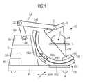
- FIG. 1shows a side view of the X-ray device
- FIG. 2shows a further side view
- FIG. 3shows a further side view
- FIG. 4shows a plan view of the X-ray device.
- a mobile X-ray devicehas a detector, which is arranged on a movable unit and assigned to a first positioning unit, and an X-ray source, which is arranged on an arc-shaped second positioning unit.
- a mobile X-ray device REis shown in FIG. 1 .
- the X-ray device REhas respective positioning units GA, CB, which are controllable independently of each other.
- the X-ray source RQ and the detector Dcan be controlled in orientation with each other. In the illustrated orientation, the X-ray cone RK emanating from the X-ray source RQ is detected by the detector D.
- the detector Dis guided by a first positioning unit GA
- the X-ray source RQis guided by a second positioning unit CB.
- the first and second positioning units GA, CBare designed in such a way that the detector D and the X-ray source RQ can be aligned with each other.
- the X-ray beam or X-ray cone RK of the X-ray source RQcan be moved, for X-ray images, around the object, tracking a rotary and/or orbital trajectory of the detector D.
- the mobile X-ray device REhas a movable unit FE.
- the latteris designed in such a way that a chassis C, receiving the first positioning unit GA, and first guide elements FGE 1 for parts of the second positioning unit CB are arranged on it.
- Second guide elements FGE 2 for guiding parts of the second positioning unit CBare arranged on the chassis C.
- the movable unit FEis equipped with transport units, for example rollers or wheels R. The transport units can be controlled manually and/or electronically.
- a control computerfor control elements for positioning the first and second positioning units GA, CB, and an image computer BR, for processing 2D X-ray images and for computing a data volume, formed by a multiplicity of 2D X-ray images, to give slice images or a 3D representation of X-rayed objects, are provided in the chassis C.
- control computer SRcontrol signals relating to the park position and repositioning of the mobile X-ray device RE can be initiated.
- the first positioning unit GAis configured with a first and a second articulated arm GA 1 , GA 2 .
- the first and/or second articulated arm GA 1 , GA 2can have telescopic elements.
- the first articulated arm GA 1is connected to the chassis C via a first articulation G 1
- the first articulated arm GA 1 and the second articulated arm GA 2are connected by a second articulation G 2
- the detector unit Dis connected to a third articulation G 3 at the free end of the second articulated arm GA 2 .
- the first, second and third articulations G 1 , G 2 , G 3are all lockable and each have at least one degree of freedom.
- the second positioning unit CBis configured with a first and a second positioning element CB 1 , CB 2 .
- the detector Dis secured on the second articulated arm GA 2
- the X-ray source RQis secured on a second positionable element CB 1 , so as to be movable to all sides via controllable articulations.
- the first and second positioning elements CB 1 , CB 2 of the second positioning unit CBare configured like arcs of a circle.
- the first positioning element CB 1forms a first, outer arc of a circle
- the second positioning element CB 2forms a second, inner arc of a circle.
- the first positioning element CB 1is guided and fixed on the chassis C at least by the first guide element FGE 1 in the floor area of the movable unit FE and/or by the second guide element FGE 2 .
- the second positioning element CB 2lies in the first positioning element CB 1 and is connected thereto via guide elements.
- the orientation of the first positioning element CB 1 and of the second positioning element CB 2can take place along the indicated first and second directions of movement BW 1 and BW 2 .
- the detector Dcan be oriented to match the orientation of the X-ray source RQ.
- the second positioning element CB 2can also be enclosed at least on three sides by the first positioning element CB 1 .
- the position of the X-ray source RQ arranged at/on the second positioning element CB 2can be obtained by telescopic deployment of the second positioning element CB 2 from the first positioning element CB 1 .
- the movable unit FEis equipped with rollers or wheels R. These rollers or wheels R are controllable via the control computer and via control electronics in such a way that a direction of travel for the X-ray unit RE can be predefined.
- the direction of travelcan be assisted by sensors. Repositioning can be carried out by electromagnetic and/or optical navigation systems. Adjustment and orientation of the rollers or wheels R can be assisted by an electric motor drive.
- the directions of movement of the mobile X-ray unit REare indicated by the directions of movement BWR.
- motor assistanceis also provided in driving the rollers and/or wheels R for transporting the X-ray device RE from and to a site of use.
- FIGS. 2 and 3each show possible orientations of the detector D and of the X-ray source RQ of the X-ray device RE.
- the detector Dis shown positioned to the side of the bed L and positioned below the bed L, respectively.
- the X-ray source RQis oriented to the side of or above the patient P.
- the X-ray source RQmoves on an arc of a circle about the patient P or about the bed L.
- the first and second arc-shaped positioning elements CB 1 , CB 2are designed in such a way that they can form at least a half circle about the object P.
- the X-ray source RQis able to describe a complete circle around the patient P.
- a plurality of 2D X-ray images of the patient Pcan be taken and, in an image computer unit not shown or described in detail here, can be processed to give slice images and/or a 3D data record. With subsequent processing programs, individual slice images and/or 3D images can then be created from the 3D data record and can be assessed for diagnostic purposes.
- FIG. 4shows a plan view of the mobile X-ray device RE.
- This illustrationshows a configuration of the articulated arms GA 1 , GA 2 connected by means of the articulations G 1 , G 2 .
- the first articulation G 1engages in fastening and driving means BA arranged in the chassis C.
- the part of the first articulation G 1 protruding from the chassis Cis connected to the first articulated arm GA 1 .
- a lateral arrangement of the first and second articulated arms GA 1 , GA 2 on the chassis Cis shown.
- the detector Dis arranged at the end of the second articulated arm GA 2 , via a third articulation G 3 . In this orientation of the detector D, it is positioned above the patient P.
- This illustrationlikewise shows that the second positioning element CB is composed of a first arc-shaped positioning element CB 1 and of a second arc-shaped positioning element CB 2 .
- the second positioning element CB 2engages in guide elements which are formed in the first positioning element CB 1 .
- a positioning of the detector D and the positioning of the X-ray source RQcan take place manually or by motor or partially by motor.
- the X-ray source RQcan also be kept stationary, while the beam direction of the X-ray source RQ tracks the trajectory of the detector D.
- a tracking of the detector D or an orientation of the detector Dcan take place according to the adjustment of the beam orientation. When a trajectory is determined by the surgical team, this trajectory can be navigated independently and fully electronically with the aid of electric motors.
- the X-ray source RQis secured on the inner of two arc-shaped positioning elements CB 1 , CB 2 running one inside the other.
- both arc-shaped positioning elements CB 1 , CB 2adopt their parked position near the movable unit FE.
- the detector Dis able to be oriented, on the one hand, and the surgeon or the radiologist, on the other hand, can be shown which region of the patient is being radiated.
Landscapes
- Health & Medical Sciences (AREA)
- Life Sciences & Earth Sciences (AREA)
- Engineering & Computer Science (AREA)
- Medical Informatics (AREA)
- Biomedical Technology (AREA)
- Animal Behavior & Ethology (AREA)
- Veterinary Medicine (AREA)
- Nuclear Medicine, Radiotherapy & Molecular Imaging (AREA)
- Public Health (AREA)
- Pathology (AREA)
- Radiology & Medical Imaging (AREA)
- General Health & Medical Sciences (AREA)
- Heart & Thoracic Surgery (AREA)
- Molecular Biology (AREA)
- Surgery (AREA)
- Physics & Mathematics (AREA)
- Biophysics (AREA)
- Optics & Photonics (AREA)
- High Energy & Nuclear Physics (AREA)
- Robotics (AREA)
- Automation & Control Theory (AREA)
- Apparatus For Radiation Diagnosis (AREA)
Abstract
Description
- RE X-ray device
- P patient
- L bed
- D detector
- RQ X-ray source
- RK X-ray cone
- IZ isocenter
- C chassis
- BA fastening and driving means
- SR control computer
- BR image computer
- GA first positioning unit
- GA1 first articulated arm of the first positioning unit
- GA2 second articulated arm of the first positioning unit
- G1 first articulation
- G2 second articulation
- G3 third articulation
- CB second positioning unit
- CB1 first positioning element of the second positioning unit
- CB2 second positioning element of the second positioning unit
- FE movable unit
- FGE1 first guide element
- FGE2 second guide element
- BW1 first directions of movement
- BW2 second directions of movement
- R rollers/wheels
- BWR directions of movement
Claims (16)
Applications Claiming Priority (4)
| Application Number | Priority Date | Filing Date | Title |
|---|---|---|---|
| DE102013205494.7ADE102013205494B4 (en) | 2013-03-27 | 2013-03-27 | X-ray machine |
| DE102013205494 | 2013-03-27 | ||
| DE102013205494.7 | 2013-03-27 | ||
| PCT/EP2014/051982WO2014154382A1 (en) | 2013-03-27 | 2014-02-03 | X-ray device |
Publications (2)
| Publication Number | Publication Date |
|---|---|
| US20160045177A1 US20160045177A1 (en) | 2016-02-18 |
| US9782139B2true US9782139B2 (en) | 2017-10-10 |
Family
ID=50033543
Family Applications (1)
| Application Number | Title | Priority Date | Filing Date |
|---|---|---|---|
| US14/779,099ActiveUS9782139B2 (en) | 2013-03-27 | 2014-02-03 | X-ray device |
Country Status (4)
| Country | Link |
|---|---|
| US (1) | US9782139B2 (en) |
| CN (1) | CN105101876B (en) |
| DE (1) | DE102013205494B4 (en) |
| WO (1) | WO2014154382A1 (en) |
Cited By (2)
| Publication number | Priority date | Publication date | Assignee | Title |
|---|---|---|---|---|
| US20170215826A1 (en)* | 2016-02-03 | 2017-08-03 | Globus Medical, Inc. | Portable medical imaging system |
| US11147525B2 (en)* | 2016-11-04 | 2021-10-19 | Hologic, Inc. | Medical imaging device and method of operating a medical imaging device |
Families Citing this family (4)
| Publication number | Priority date | Publication date | Assignee | Title |
|---|---|---|---|---|
| JP6654884B2 (en)* | 2015-12-11 | 2020-02-26 | 川崎重工業株式会社 | Surgery system |
| JP2019063877A (en)* | 2017-09-28 | 2019-04-25 | ファナック株式会社 | robot |
| US10517554B1 (en)* | 2018-09-07 | 2019-12-31 | Shimadzu Corporation | X-ray fluoroscopic imaging apparatus |
| DE102022000617A1 (en) | 2022-02-18 | 2023-08-24 | Medizintechnik St. Egidien Gmbh | Support system for an X-ray device for flexible positioning |
Citations (14)
| Publication number | Priority date | Publication date | Assignee | Title |
|---|---|---|---|---|
| US3617749A (en)* | 1970-01-12 | 1971-11-02 | Philips Corp | Column support for x-ray apparatus |
| US6104780A (en)* | 1997-11-24 | 2000-08-15 | Oec Medical Systems, Inc. | Mobile bi-planar fluoroscopic imaging apparatus |
| US6256374B1 (en)* | 1998-10-19 | 2001-07-03 | Fluoroscan Imaging Systems, Inc. | Miniature C-arm apparatus with dual video display monitor and single driver interface therefor |
| US6325537B1 (en) | 1998-10-16 | 2001-12-04 | Kabushiki Kaisha Toshiba | X-ray diagnosis apparatus |
| US6428206B1 (en) | 1999-02-12 | 2002-08-06 | Kabushiki Kaisha Toshiba | X-ray diagnostic imaging apparatus |
| US20030112926A1 (en)* | 2001-12-13 | 2003-06-19 | Siemens Aktiengesellschaft | X-ray apparatus |
| US6619840B2 (en)* | 2001-10-15 | 2003-09-16 | Koninklijke Philips Electronics N.V. | Interventional volume scanner |
| US20080089468A1 (en)* | 2006-09-01 | 2008-04-17 | Siemens Aktiengesellschaft | Method for reconstructing a three-dimensional image volume and x-ray devices |
| US20100303207A1 (en) | 2009-06-02 | 2010-12-02 | Canon Kabushiki Kaisha | Radiation imaging apparatus and method for controlling radiation imaging apparatus |
| DE102011006122A1 (en) | 2011-03-25 | 2012-09-27 | Siemens Aktiengesellschaft | Medical X-ray apparatus has C-bow-shaped support device comprising partial arms formed as robot arm by two joints |
| DE102011082075A1 (en) | 2011-09-02 | 2013-03-07 | Siemens Aktiengesellschaft | X-ray device has X-ray source, X-ray detector and center arranged between X-ray source and X-ray detector along central beam, where X-ray source and X-ray detector are arranged at separate carrying arms |
| US20140188132A1 (en)* | 2012-12-31 | 2014-07-03 | Mako Surgical Corp. | System for image-based robotic surgery |
| US20150049862A1 (en)* | 2012-04-24 | 2015-02-19 | Portavision Medical Llc | Mobile Imaging System And Method |
| US20150265237A1 (en)* | 2012-10-22 | 2015-09-24 | Fraunhofer-Gesellschaft zur Förderung der angewandten Forschung e.V. | Method and device for generating a three-dimensional image of an object |
- 2013
- 2013-03-27DEDE102013205494.7Apatent/DE102013205494B4/enactiveActive
- 2014
- 2014-02-03WOPCT/EP2014/051982patent/WO2014154382A1/enactiveApplication Filing
- 2014-02-03USUS14/779,099patent/US9782139B2/enactiveActive
- 2014-02-03CNCN201480018453.5Apatent/CN105101876B/enactiveActive
Patent Citations (16)
| Publication number | Priority date | Publication date | Assignee | Title |
|---|---|---|---|---|
| US3617749A (en)* | 1970-01-12 | 1971-11-02 | Philips Corp | Column support for x-ray apparatus |
| US6104780A (en)* | 1997-11-24 | 2000-08-15 | Oec Medical Systems, Inc. | Mobile bi-planar fluoroscopic imaging apparatus |
| US6325537B1 (en) | 1998-10-16 | 2001-12-04 | Kabushiki Kaisha Toshiba | X-ray diagnosis apparatus |
| US6256374B1 (en)* | 1998-10-19 | 2001-07-03 | Fluoroscan Imaging Systems, Inc. | Miniature C-arm apparatus with dual video display monitor and single driver interface therefor |
| US6428206B1 (en) | 1999-02-12 | 2002-08-06 | Kabushiki Kaisha Toshiba | X-ray diagnostic imaging apparatus |
| US6619840B2 (en)* | 2001-10-15 | 2003-09-16 | Koninklijke Philips Electronics N.V. | Interventional volume scanner |
| US20030112926A1 (en)* | 2001-12-13 | 2003-06-19 | Siemens Aktiengesellschaft | X-ray apparatus |
| US20080089468A1 (en)* | 2006-09-01 | 2008-04-17 | Siemens Aktiengesellschaft | Method for reconstructing a three-dimensional image volume and x-ray devices |
| US20100303207A1 (en) | 2009-06-02 | 2010-12-02 | Canon Kabushiki Kaisha | Radiation imaging apparatus and method for controlling radiation imaging apparatus |
| DE102011006122A1 (en) | 2011-03-25 | 2012-09-27 | Siemens Aktiengesellschaft | Medical X-ray apparatus has C-bow-shaped support device comprising partial arms formed as robot arm by two joints |
| DE102011082075A1 (en) | 2011-09-02 | 2013-03-07 | Siemens Aktiengesellschaft | X-ray device has X-ray source, X-ray detector and center arranged between X-ray source and X-ray detector along central beam, where X-ray source and X-ray detector are arranged at separate carrying arms |
| US20130223597A1 (en)* | 2011-09-02 | 2013-08-29 | Siemens Aktiengesellschaft | X-ray facility having a recording arrangement held on support arms |
| US8944680B2 (en) | 2011-09-02 | 2015-02-03 | Siemens Aktiengesellschaft | X-ray facility having a recording arrangement held on support arms |
| US20150049862A1 (en)* | 2012-04-24 | 2015-02-19 | Portavision Medical Llc | Mobile Imaging System And Method |
| US20150265237A1 (en)* | 2012-10-22 | 2015-09-24 | Fraunhofer-Gesellschaft zur Förderung der angewandten Forschung e.V. | Method and device for generating a three-dimensional image of an object |
| US20140188132A1 (en)* | 2012-12-31 | 2014-07-03 | Mako Surgical Corp. | System for image-based robotic surgery |
Cited By (5)
| Publication number | Priority date | Publication date | Assignee | Title |
|---|---|---|---|---|
| US20170215826A1 (en)* | 2016-02-03 | 2017-08-03 | Globus Medical, Inc. | Portable medical imaging system |
| US11058378B2 (en)* | 2016-02-03 | 2021-07-13 | Globus Medical, Inc. | Portable medical imaging system |
| US11147525B2 (en)* | 2016-11-04 | 2021-10-19 | Hologic, Inc. | Medical imaging device and method of operating a medical imaging device |
| US20220071579A1 (en)* | 2016-11-04 | 2022-03-10 | Hologic, Inc. | Medical imaging device and method of operating a medical imaging device |
| US11839505B2 (en)* | 2016-11-04 | 2023-12-12 | Hologic, Inc. | Medical imaging device and method of operating a medical imaging device |
Also Published As
| Publication number | Publication date |
|---|---|
| DE102013205494A1 (en) | 2014-10-02 |
| CN105101876B (en) | 2019-02-12 |
| US20160045177A1 (en) | 2016-02-18 |
| CN105101876A (en) | 2015-11-25 |
| DE102013205494B4 (en) | 2021-02-18 |
| WO2014154382A1 (en) | 2014-10-02 |
Similar Documents
| Publication | Publication Date | Title |
|---|---|---|
| US9782139B2 (en) | X-ray device | |
| US10159453B2 (en) | Transformable imaging system | |
| JP6866382B2 (en) | Portable medical imaging system | |
| US11564646B2 (en) | Transformable imaging system | |
| JP5848005B2 (en) | A system for automatic support of object positioning in moving image acquisition | |
| US9089309B2 (en) | Multiplane medical imaging system | |
| US7354196B2 (en) | Device for recording projection images | |
| US11883217B2 (en) | Portable medical imaging system and method | |
| JP6563891B2 (en) | Robotic operating table and hybrid operating room | |
| CN102164636B (en) | Image-guided multi-source radiotherapy | |
| EP3086734B1 (en) | Object tracking device | |
| US20160082596A1 (en) | Mobile medical apparatus | |
| US9033575B2 (en) | Arc-shaped medical imaging equipment | |
| US20130276232A1 (en) | Iso-roll table | |
| DE102010061199A1 (en) | Systems and methods for automatically supporting mobile image capture | |
| CN113133782A (en) | Mobile platform and system comprising a plurality of mobile platforms | |
| CN106714691B (en) | Mobile X-ray apparatus | |
| DE102019209543A1 (en) | Method for providing collision information and medical imaging device | |
| CN103654817B (en) | Apparatus and method for positioning medical supply | |
| US9855015B2 (en) | Transformable imaging system | |
| CN105011957A (en) | X-ray imaging equipment, target imaging system and target imaging method | |
| CN204863237U (en) | X ray image equipment and target area imaging system | |
| JP2004216193A (en) | Two-way x-ray fluorography equipment | |
| HK40001555A (en) | Portable medical imaging system | |
| HK40001555B (en) | Portable medical imaging system |
Legal Events
| Date | Code | Title | Description |
|---|---|---|---|
| AS | Assignment | Owner name:SIEMENS AKTIENGESELLSCHAFT, GERMANY Free format text:ASSIGNMENT OF ASSIGNORS INTEREST;ASSIGNORS:BARTH, KARL;GRAUMANN, RAINER;SIGNING DATES FROM 20150824 TO 20150901;REEL/FRAME:036706/0400 | |
| STCF | Information on status: patent grant | Free format text:PATENTED CASE | |
| AS | Assignment | Owner name:SIEMENS HEALTHCARE GMBH, GERMANY Free format text:ASSIGNMENT OF ASSIGNORS INTEREST;ASSIGNOR:SIEMENS AKTIENGESELLSCHAFT;REEL/FRAME:046100/0015 Effective date:20180518 | |
| MAFP | Maintenance fee payment | Free format text:PAYMENT OF MAINTENANCE FEE, 4TH YEAR, LARGE ENTITY (ORIGINAL EVENT CODE: M1551); ENTITY STATUS OF PATENT OWNER: LARGE ENTITY Year of fee payment:4 | |
| AS | Assignment | Owner name:SIEMENS HEALTHINEERS AG, GERMANY Free format text:ASSIGNMENT OF ASSIGNORS INTEREST;ASSIGNOR:SIEMENS HEALTHCARE GMBH;REEL/FRAME:066088/0256 Effective date:20231219 | |
| AS | Assignment | Owner name:SIEMENS HEALTHINEERS AG, GERMANY Free format text:CORRECTIVE ASSIGNMENT TO CORRECT THE ASSIGNEE PREVIOUSLY RECORDED AT REEL: 066088 FRAME: 0256. ASSIGNOR(S) HEREBY CONFIRMS THE ASSIGNMENT;ASSIGNOR:SIEMENS HEALTHCARE GMBH;REEL/FRAME:071178/0246 Effective date:20231219 | |
| FEPP | Fee payment procedure | Free format text:MAINTENANCE FEE REMINDER MAILED (ORIGINAL EVENT CODE: REM.); ENTITY STATUS OF PATENT OWNER: LARGE ENTITY |