US9780892B2 - System and method for aligning a radio using an automated audio guide - Google Patents
System and method for aligning a radio using an automated audio guideDownload PDFInfo
- Publication number
- US9780892B2 US9780892B2US14/639,976US201514639976AUS9780892B2US 9780892 B2US9780892 B2US 9780892B2US 201514639976 AUS201514639976 AUS 201514639976AUS 9780892 B2US9780892 B2US 9780892B2
- Authority
- US
- United States
- Prior art keywords
- wireless radio
- signal strength
- tone
- radio
- directional wireless
- Prior art date
- Legal status (The legal status is an assumption and is not a legal conclusion. Google has not performed a legal analysis and makes no representation as to the accuracy of the status listed.)
- Active
Links
Images


Classifications
- H—ELECTRICITY
- H04—ELECTRIC COMMUNICATION TECHNIQUE
- H04B—TRANSMISSION
- H04B17/00—Monitoring; Testing
- H04B17/20—Monitoring; Testing of receivers
- H04B17/23—Indication means, e.g. displays, alarms, audible means
- H—ELECTRICITY
- H04—ELECTRIC COMMUNICATION TECHNIQUE
- H04B—TRANSMISSION
- H04B17/00—Monitoring; Testing
- H04B17/30—Monitoring; Testing of propagation channels
- H04B17/309—Measuring or estimating channel quality parameters
- H04B17/318—Received signal strength
- H04W4/008—
- H—ELECTRICITY
- H04—ELECTRIC COMMUNICATION TECHNIQUE
- H04W—WIRELESS COMMUNICATION NETWORKS
- H04W4/00—Services specially adapted for wireless communication networks; Facilities therefor
- H04W4/80—Services using short range communication, e.g. near-field communication [NFC], radio-frequency identification [RFID] or low energy communication
Definitions
- the present inventionrelates to radio installation systems and methods.
- the present system and methodenables an individual installation technician to receive aural indications of signal strength while installing a radio.
- the present technologyis directed to a method comprising: (a) receiving a signal strength corresponding to a long range wireless link established between a first directional wireless radio and a second wireless radio, the signal strength varying over time as the first directional wireless radio is aligned with a second wireless radio by an installer, wherein the signal strength is received over a short range wireless link from a short range wireless radio associated with the first directional wireless radio; and (b) producing a sound indicator indicative of the signal strength, wherein the sound indicator varies over time as the first directional wireless radio is aligned with the second wireless radio by the installer.
- the present technologyis directed to a method comprising: (a) executing an audible alignment application by a single installer using a mobile device, the audible alignment application being stored in memory and executable by a processor of the mobile device; and (b) aligning a first directional wireless radio with a second wireless radio by: (i) bringing the mobile device in proximity to the first directional wireless radio; (ii) receiving a signal strength corresponding to a long range wireless link established between the first directional wireless radio and the second wireless radio, the signal strength varying over time as the first directional wireless radio is aligned with a second wireless radio by the single installer; and (iii) producing a sound indicator indicative of the signal strength, wherein the sound indicator varies over time as the first directional wireless radio is aligned with the second wireless radio by the single installer.
- the present technologyis directed to a non-transitory computer readable storage media having a program embodied thereon, the program being executable by a processor to perform a method, comprising: (i) coupling a mobile device with a first directional wireless radio using a wireless communication protocol; (ii) receiving a signal strength corresponding to a long range wireless link established between a first directional wireless radio and a second wireless radio, the signal strength varying over time as the first directional wireless radio is aligned with a second wireless radio by an installer; and (iii) producing a sound indicator indicative of a comparison of the signal strength to an optimal signal strength value that aids in alignment of the first directional wireless radio and a second wireless radio
- the present technologyis directed to a system, comprising: (a) a first directional wireless radio; and (b) a mobile device that is communicatively coupled with the first directional wireless radio, wherein the mobile device is configured to: (i) measure a location and signal strength of the first directional wireless radio relative to a second wireless radio, in a plurality of radio positions; (ii) determine an optimal radio position from the plurality of radio positions; and (iii) output a varying sound signal that aids an installer in bringing the first directional wireless radio into alignment with the second wireless radio, the varying sound signal based on a comparison of the signal strength to an optimal signal strength value.
- FIG. 1is a block diagram of an exemplary system, constructed in accordance with embodiments of the present technology.
- FIG. 2illustrates an example radio alignment process and variable sound output graph.
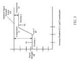
- FIG. 3is a graph that illustrates the use of an optimal signal strength value to assist an installer in radio alignment.
- FIG. 4is a flowchart of an example method of the present technology.
- FIG. 5is a flowchart of another example method of the present technology.
- FIG. 6illustrates an exemplary computing system that may be used to implement embodiments according to the present technology.
- Wireless radiosmay have geometries that cause performance to vary with orientation.
- Microwave radiosmay be used to transmit broadband internet connections between fixed points, for instance between an Internet Service Provider (ISP) and a customer or group of customers.
- ISPInternet Service Provider
- Microwave radiosmay therefore have fixed orientations having a significant impact on data throughput.
- the installation of radiosmay be a time-consuming operation that may have a consequently large impact on the cost of adopting a new ISP. Reducing the number of people required to install a radio, for instance from two people to one person, can have a dramatic impact on costs.
- a two person installation teammay require one person to physically install/adjust the wireless radio, and a second person to monitor signal strength received at the radio and guide the physical installer in adjusting the elevation and azimuth of the radio.
- the present technologymay utilize a smart phone connected to the radio, either by WiFi or other short range wireless link, such that the installer hears human speech, or another aural indication, to direct the alignment.
- a smart phoneconnected to the radio, either by WiFi or other short range wireless link, such that the installer hears human speech, or another aural indication, to direct the alignment.
- the installercan put the phone into a pocket, leaving both hands free for radio alignment.
- the Voice Guided Radio Alignment method and system provided hereinmay be integrated into a radio system to assist in installation, or the radio system may include a WiFi, Bluetooth or other secondary communication system for transmitting a signal strength of the signal being received at the radio being installed, such as a long range wireless link between a first radio and a second radio.
- the WiFi, Bluetooth or other secondary communication systemmay couple the radio to a smartphone, laptop or personal digital assistant to produce an aural indication of strength.
- the aural indication of strengthmay be volume, for instance increasing volume as the signal strength increases.
- the aural indicationmay vary in tone to indicate strength, for instance rising (or alternatively, lowering) in tone as the signal strength increases.
- the aural indicationmay be a voice indicating an absolute strength of the signal, e.g., a number, or a relative strength of the signal, e.g. stronger or weaker.
- the aural indicationmay be made periodically, for instance every two seconds or five seconds (or in any other possible periodicity, or adjustably periodically), or may be made in response to a voice input made by the person installing the radio (e.g., “now?”, “strength?”, or “reading?).
- a signal including an SSIDmay be received.
- Further alignmentrequires an indication of signal strength, which in prior art systems may include LEDs with gradations of 10 dBm.
- this systemmay be too granular and not very accurate, and consequently not as helpful to the installer.
- the LEDsmay be in a position that may not always be visible, for instance on a back side of a radio or radio housing.
- Alternative prior art systemsmay use two installers, with one installer physically moving and adjusting the radio, either in elevation or azimuth alternately, while a second installer uses a laptop to monitor an indication of signal strength received at the radio.
- the present technologyprovides an application for a smartphone, for instance an iPhone or an Android phone, that provides a voice indication (or other aural indication) of signal strength.
- the aural indication of signal strengthmay be provided periodically or on demand in response to a voice input from the installer.
- the radio being installedmay include a WiFi, Bluetooth, or other communication method for communicating a strength of the signal (for example, the microwave signal) being received to the smartphone.
- the radio systemmay include an integrated automatic aural adjustment system, which may include, along with a system for measuring a strength of the microwave (or other incoming) signal, a speaker for producing sound, and a memory for storing sound indications, for instance speech or tones (e.g. a “.wav” file).
- the volume of the speakermay vary depending on the strength of the signal, alternatively or in addition to speech indications and/or tonal change indications.
- Still further alternativesmay use a smartphone or other internet-enabled device to access a mapping program (e.g., Google MapsTM) to assist in initial alignment, and/or may record signal strength results during, or at the conclusion of, the installation process.
- a mapping programe.g., Google MapsTM
- the signal strength resultsmay be recorded in the smartphone and/or transmitted to a central location for storage and/or analysis.
- the aural adjustment systemincluding the system for measuring a strength of the microwave (or other incoming) signal may be integrated into a management system and/or a management radio used to administer the remote radio system.
- the management of the radio systemmay be in a different band than the microwave (or other wavelength) primary signal carrier in order to avoid interference with the primary signal and/or with the management of the radio system.
- the present technologycan employ methods for determining an optimal signal strength value from a variety of radio alignment attributes.
- the optimal signal strength valueis utilized to align a first wireless radio with a second wireless radio by bringing an actual signal strength into correspondence with the optimal signal strength value by making adjustments to the alignment of the first directional wireless radio and second wireless radio.
- the applicationmay be a mobile application, and/or may be used on a laptop, smartphone or PDA, and may be downloadable or web-based.
- the systemmay be implemented in software and/or hardware.
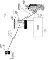
- the environment 100comprises a second wireless radio 102 that is located remotely from a first directional wireless radio 104 .
- the first directional wireless radio 104can be disposed anywhere, such as on the outside of a structure or inside the structure.
- An installer 108can align the first directional wireless radio 104 with the second wireless radio 102 using a mobile device 110 , such as a tablet, Smartphone, or other computing device that couples with the first directional wireless radio 104 .
- a mobile device 110such as a tablet, Smartphone, or other computing device that couples with the first directional wireless radio 104 .
- the second wireless radio 102can include another radio, a MIMO (Multiple Input Multiple Output) radio, a satellite, a broadcast tower, a cellular network, a WiFi hotspot or access point, or any other device that is configured to transmit and/or receive a signal.
- the first directional wireless radio 104can also comprise any device that is configured to transmit and/or receive signals from the second wireless radio 102 .
- the first directional wireless radio 104 and second wireless radio 102are communicatively coupled over a long range wireless link 107 .
- a signal strength of the long range wireless link 107selectively varies as the first directional wireless radio 104 and second wireless radio 102 are brought into alignment with one another by an installer 108 .
- the present technologyadvantageously allows the installer 108 to receive signal strength information from the first directional wireless radio 104 in a hands-free manner. That is, once the installer 108 executes The App, the mobile device 110 begins to receive the signal strength from by communicating with the short range radio 105 over a short range wireless link 109 .
- the installer 108receives aural indications of the signal strength and/or a relative alignment between the first directional wireless radio 104 and second wireless radio 102 without having to further interact with mobile device 110 , which leaves the installer 108 free to adjust a position of the first directional wireless radio 104 with both hands while receiving alignment feedback on their mobile device 110 .
- the first directional wireless radio 104includes a radio and long range antenna that are integrated into a single housing or enclosure, along with the short range wireless radio 105 .
- the radio and long range antennaare not integrated into the same housing.
- the long range (e.g., high gain) antennacan still be integrated with the short range wireless radio 105 , even in these embodiments where the radio is separate.
- the second wireless radio 102 and first directional wireless radio 104can communicate wirelessly when they are properly aligned with one another. To be sure, misalignment between the second wireless radio 102 and the first directional wireless radio 104 can result in signal degradation and poor connectivity there between.
- the mobile device 110is communicatively coupled with the first directional wireless radio 104 using a short range wireless communications protocol such as Bluetooth, Infrared, Near Field Communications, or through a WiFi connection.
- the first directional wireless radio 104comprises or is coupled to a short range radio 105 .
- the mobile device 110communicates with the short range radio 105 over a short range wireless link 109 .
- the first directional wireless radio 104may couple with a WiFi access point in the structure.
- the mobile device 110can also couple with the WiFi access point and communicate with the first directional wireless radio 104 over the wireless network established by the WiFi access point.
- the installer 108can use the mobile device 110 to communicate with the first directional wireless radio 104 to receive signals from the radio that are indicative of a signal strength being received by the first directional wireless radio 104 from the second wireless radio 102 . Again, the signal strength relates to the long range wireless link 107
- the mobile device 110comprises, in some embodiments, a processor and memory that are configured to store and execute instructions such as a radio alignment application (“The App”), as illustrated in FIG. 2 .
- the Appa radio alignment application
- FIG. 2also illustrates an example radio alignment process. While the alignment process in FIG. 2 is illustrated as a two dimensional alignment process (e.g., a combination of X and Y coordinates changed through rotation of the first directional wireless radio 104 about a central point A), the first directional wireless radio 104 can be aligned in three dimensions such as X, Y, and Z. To be sure, the Z axis would include vertical movement along the central point A.
- the alignment process in FIG. 2is illustrated as a two dimensional alignment process (e.g., a combination of X and Y coordinates changed through rotation of the first directional wireless radio 104 about a central point A)
- the first directional wireless radio 104can be aligned in three dimensions such as X, Y, and Z.
- the Z axiswould include vertical movement along the central point A.
- the first directional wireless radio 104is illustrated as being in Position 1 originally, where a broadcast pattern B 1 of the first directional wireless radio 104 is only partially aligned with the second wireless radio 102 .
- initial signal strength S 1is received by the mobile device 110 .
- the initial signal strength S 1can be output by a speaker of the mobile device 110 as, for example, a tone having a variable frequency, a pulse tone that varies in pulse rate, a speech synthesized output that is representative of the initial signal strength such as “ ⁇ 20 dBm”, as well as other variable audio output by the speaker.
- the mobile device 110can also vibrate to indicate signal strength.
- the installer 108rotates the first directional wireless radio 104 to the left, about the central point A, the first directional wireless radio 104 is rotated into Position 2 .
- the signal strengthchanges as the first directional wireless radio 104 rotates between Position 1 and Position 2 .
- the sound output by the mobile device 110 at Position 1is different from the sound output by the mobile device 110 at Position 2 , the sound output will vary between Position 1 and Position 2 , as the first directional wireless radio 104 is moved.
- the signal strengthchanges from ⁇ 20 dBm to ⁇ 40 dBm.
- An example of varying output by the mobile device 110would include a tone having a first frequency being output by the mobile device 110 in response to signal strength S 1 .
- the tonewould increase in frequency between the first frequency and a final frequency as the radio is transitioned from Position 1 to Position 2 . That is, the tone of output by the mobile device 110 steadily changes until reaching a final frequency associated with the signal strength S 2 .
- the signal strength region S 3has a varying signal strength, which causes the mobile device 110 to generate an output of varying intensity.
- the mobile device 110can be configured (through The App) to output varying pulses of a single tone frequency or varying speech output.
- the mobile device 110is configured through The App to calculate or approximate the optimal signal strength value. For example, when installing and aligning a radio with a second wireless radio, the installer may not know what the optimal signal strength value should be.
- the optimal signal strength valuecan be calculated using a plurality of signal strength determination attributes.
- the mobile device 110is configured to determine a GPS location of the directional first wireless radio 104 .
- the mobile device 110can look up a location for the second wireless radio 102 from a database. Knowing the distance, the mobile device 110 can calculate an approximate optimal signal strength value. When the first directional wireless radio 104 and second wireless radio 102 are aligned properly at the determined distance, the actual or measured signal strength at the first directional wireless radio 104 should equal the optimal signal strength value.
- the distance between the first directional wireless radio 104 and the second wireless radio 102can be correlated to a free space path loss value, which is a loss in signal strength of an electromagnetic wave that would result from a line-of-sight path through free space.
- Additional signal strength determination attributescomprise a conductive transmit power level, a transmit radio (e.g., antenna) gain, a receive radio (e.g., antenna) gain, as well as the free space path loss.
- the optimal signal strength valueis calculated as a logarithmic of the conductive transmit power level, plus the transmit radio gain, minus free space path loss, plus receive radio gain.
- the optimal signal strength valuecan be refined by using additional signal strength determination attributes.
- additional signal strength determination attributesFor example, atmospheric attenuation can be utilized as another signal strength determination attribute. To be sure, attenuating values are negative values in the logarithmic equation set forth above.
- the signal strength determination attributescan also comprise estimated obstructive losses/attenuation caused by line-of-sight obstacles such as trees, brush, buildings, and so forth. In yet other embodiments, the signal strength determination attributes can also comprise losses from cables or other hardware associated with the first directional wireless radio 104 .
- the mobile device 110can determine if there is vegetative loss through trees that will impact the optimal signal strength value.
- the two linked radiose.g., first directional wireless radio and the second wireless radio
- the mobile device 110can determine the rain fade that will impact the target signal strength.
- current weather datasuch as the current rate of precipitation
- the mobile device 110is configured to output the optimal signal strength value at the beginning of an alignment procedure.
- the mobile device 110 and first directional wireless radio 104may be configured to output the optimal signal strength value in speech form to inform the installer of the optimal signal strength value that is required for proper alignment.
- the installerneed only adjust the position of the first directional wireless radio 104 as the mobile device 110 outputs the actual signal strength as variable sound output.
- the first directional wireless radio 104 and second wireless radio 102are aligned.
- the installercan utilize the mobile device 110 to output the optimal signal strength value if the installer does not recall the optimal signal strength value.
- the mobile device 110can be configured to utilize an optimal signal strength value 122 for outputting one or more additional tones.
- the mobile device 110can perform comparisons between the optimal signal strength value 122 and the actual signal strength being measured at the first directional wireless radio 104 and use this measured comparison to output information to the installer 108 (see FIG. 1 ).
- the optimal signal strength value 122is ⁇ 60 dBm.
- the mobile device 110measures the signal strength S 1 of ⁇ 20 dBm and generates a Comparison 11 having a value of ⁇ 40 dBm.
- the mobile device 110generates a Comparison 22 having a value of ⁇ 2 dBm.
- the mobile device 110can output a third type of variable output that represents the comparison value. This variable output can be used in place of, or in addition to, the variable outputs described above. For example, the mobile device 110 can use natural language speech output to call out the comparison values.
- the installer 108hears the comparison values and can appreciate that the first directional wireless radio 104 is in substantial alignment with the second wireless radio 102 when the ⁇ 2 dBm comparison value is output. That is, it is assumed that the ⁇ 2 dBm comparison value indicates that the first directional wireless radio 104 and second wireless radio 102 are in optimal (or close to) alignment.
- the mobile device 110can set a tone frequency for the optimal signal strength value 122 .
- the mobile device 110can assign to the optimal signal strength value 122 a tone of C. Any signal strength of the first directional wireless radio 104 that is measured below the optimal signal strength value 122 causes the mobile device 110 to output a tone that is lower than C (where C is located on a musical scale between A-G). The mobile device 110 can output this tone consistently through a sample alignment process.
- the mobile device 110can output another tone in addition to the constant tone assigned to the optimal signal strength value 122 .
- This toneis variable and corresponds to the actual measured signal strength for the first directional wireless radio 104 .
- the mobile device 110can set an initial tone for signal strength S 1 at A. As the measured signal strength of the first directional wireless radio 104 increases towards the optimal signal strength value 122 , the tone will increase in frequency from A towards C. Once the measured signal strength of the first directional wireless radio 104 and the optimal signal strength value 122 converge, the installer 108 will hear a single tone of C, which will indicate that the first directional wireless radio 104 and second wireless radio 102 are in alignment with one another.
- the constant tonecan be continuous or can be output intermittently by the mobile device 110 .
- the mobile device 110can use the comparison to direct the installer 108 to move the first directional wireless radio 104 in a particular direction. For example, if the installer 108 is moving the first directional wireless radio 104 in a sweeping motion to obtain a general alignment, the mobile device 110 can be configured through The App to detect a position of the first directional wireless radio 104 relative to the central position A, using for example, an accelerometer or other movement sensing device that is built into the mobile device 110 or installed into the first directional wireless radio 104 . For example, the installer 108 can place their mobile device 110 directly on the first directional wireless radio 104 to sense movement of the first directional wireless radio 104 .
- the mobile device 110can detect signal strength and location at the same time across various locations during the sweeping procedure. That is, for each signal strength taken, a location for the first directional wireless radio 104 is determined and stored.
- the mobile device 110can determine that the installer 108 should move the first directional wireless radio 104 in one direction or another (or potentially multiple directions when moving the first directional wireless radio 104 in the X, Y and Z axes) based upon the best or highest signal detected during the sweeping procedure. In another example, the mobile device 110 can determine that the installer 108 should move the first directional wireless radio 104 in one direction or another based upon comparison values, as well.
- a sweeping procedurecan be used, as well as the obtaining of multiple signal values at various points to detect a general alignment area where signal strength is increasing.
- the mobile device 110can detect the highest signal strength for the first directional wireless radio 104 at a plurality of locations (a set of X, Y, and Z), detect a current position of the first directional wireless radio 104 , and guide the installer 108 to optimal alignment through verbal output, such as speech information that tells the installer 108 to move the radio up/down, left/right, rotate, and so forth.
- a plurality of locationsa set of X, Y, and Z
- verbal outputsuch as speech information that tells the installer 108 to move the radio up/down, left/right, rotate, and so forth.
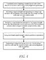
- FIG. 4illustrates an example method of the present technology.
- the methodbegins with the installer communicatively coupling 405 a mobile device with a first directional wireless radio using a radio alignment application.
- the mobile devicecan couple with the first directional wireless radio by bringing the mobile device into proximity with the first directional wireless radio.
- the alignment applicationconfigures for measurement of radio signal strength using whichever of the methods the installer desires to utilize. In this method, the installer selects to have a varying sound indicator output by the mobile device.
- the methodincludes receiving 410 a signal strength corresponding to a long range wireless link established between the first directional wireless radio and a second wireless radio.
- the signal strengthvaries over time as the first directional wireless radio is aligned with a second wireless radio by an installer.
- the signal strengthcorresponds to a long range wireless link established between the first directional wireless radio and the second wireless radio.
- the signal strengthwill vary over time as the radio is aligned with a second wireless radio by the installer.
- the methodincludes the mobile device producing 415 a sound indicator indicative of the signal strength. Again, the sound indicator varies over time as the first directional wireless radio is aligned with the second wireless radio.
- the varying sound indicatorcan include a pulsing tone of a given frequency, where the pulse rate increases or decreases in response to the increase or decrease in signal strength.
- the varying sound indicatorcan include a tone of varying frequency or a speech output of varying content, such as a natural language output that includes a verbalized representation of the signal strength compared with an optimal signal strength value.
- the methodcan include sub-method of using 420 an optimal signal strength value to perform a comparison.
- steps 405 - 415can be performed independently of steps 420 and 425 .
- the optimal signal strength valuecan be compared to the signal strength to determine a degree of misalignment between the first directional wireless radio and the second wireless radio.
- the methodincludes outputting 425 an alignment sound when the first directional wireless radio and the second wireless radio are in alignment with one another.
- the alignment soundcould include a single tone of a given frequency (which is different from other tones used in the comparison process).
- the alignment soundcould include a spoken word of “aligned”.
- FIG. 5illustrates an example, sub-method for using an optimal signal strength value during the alignment process.
- the methodcomprises a step of calculating 500 an optimal signal strength value from a conductive transmit power level, a transmit radio gain, a receive radio gain, as well as a free space path loss.
- This methodincludes storing 505 an optimal signal strength value.
- the optimal signal strength valuecomprises an expected signal strength when the first directional wireless radio and the second wireless radio are substantially in optimal alignment with one another.
- the methodincludes comparing 510 the signal strength to the optimal signal strength value.
- the methodincludes the mobile device outputting 515 either a convergence tone or a divergence tone based on the comparison.
- the convergence toneis utilized when a difference between the signal strength and the optimal signal strength value is decreasing.
- the mobile devicedetects the signal strength of alignment as the first directional wireless radio is moved by the installer.
- the mobile devicecan output a convergence tone.
- This convergence tonecould include a particular note selected from a musical scale or a chord selected from a musical scale.
- a divergence toneis utilized when a difference between the signal strength and the optimal signal strength value is increasing, such as in instances where the first directional wireless radio and second wireless radio are moving further out of alignment with one another.
- This convergence tonecould include a particular note selected from a musical scale or a chord selected from a musical scale that is different from the one selected for the convergence tone.
- FIG. 6is a diagrammatic representation of an example machine in the form of a computer system 101 , within which a set of instructions for causing the machine to perform any one or more of the methodologies discussed herein may be executed.
- the machineoperates as a standalone device or may be connected (e.g., networked) to other machines.
- the machinemay operate in the capacity of a server or a client machine in a server-client network environment, or as a peer machine in a peer-to-peer (or distributed) network environment.
- the machinemay be a robotic construction marking device, a base station, a personal computer (PC), a tablet PC, a set-top box (STB), a personal digital assistant (PDA), a cellular telephone, a portable music player (e.g., a portable hard drive audio device such as an Moving Picture Experts Group Audio Layer 3 (MP3) player), a web appliance, a network router, switch or bridge, or any machine capable of executing a set of instructions (sequential or otherwise) that specify actions to be taken by that machine.
- a portable music playere.g., a portable hard drive audio device such as an Moving Picture Experts Group Audio Layer 3 (MP3) player
- MP3Moving Picture Experts Group Audio Layer 3
- web appliancee.g., a web appliance, a network router, switch or bridge, or any machine capable of executing a set of instructions (sequential or otherwise) that specify actions to be taken by that machine.
- machineshall also be taken to include any collection of machines that individually or jointly execute a set (
- the example computer system 101includes a processor or multiple processors 5 (e.g., a central processing unit (CPU), a graphics processing unit (GPU), or both), and a main memory 10 and static memory 15 , which communicate with each other via a bus 20 .
- the computer system 101may further include a video display 35 (e.g., a liquid crystal display (LCD)).
- the computer system 101may also include an alpha-numeric input device(s) 30 (e.g., a keyboard), a cursor control device (e.g., a mouse), a voice recognition or biometric verification unit (not shown), a drive unit 37 (also referred to as disk drive unit), a signal generation device 40 (e.g., a speaker), and a network interface device 45 .
- the computer system 101may further include a data encryption module (not shown) to encrypt data.
- the disk drive unit 37includes a computer or machine-readable medium 50 on which is stored one or more sets of instructions and data structures (e.g., instructions 55 ) embodying or utilizing any one or more of the methodologies or functions described herein.
- the instructions 55may also reside, completely or at least partially, within the main memory 10 and/or within the processors 5 during execution thereof by the computer system 101 .
- the main memory 10 and the processors 5may also constitute machine-readable media.
- the instructions 55may further be transmitted or received over a network via the network interface device 45 utilizing any one of a number of well-known transfer protocols (e.g., Hyper Text Transfer Protocol (HTTP)).
- HTTPHyper Text Transfer Protocol
- the machine-readable medium 50is shown in an example embodiment to be a single medium, the term “computer-readable medium” should be taken to include a single medium or multiple media (e.g., a centralized or distributed database and/or associated caches and servers) that store the one or more sets of instructions.
- computer-readable mediumshall also be taken to include any medium that is capable of storing, encoding, or carrying a set of instructions for execution by the machine and that causes the machine to perform any one or more of the methodologies of the present application, or that is capable of storing, encoding, or carrying data structures utilized by or associated with such a set of instructions.
- the term “computer-readable medium”shall accordingly be taken to include, but not be limited to, solid-state memories, optical and magnetic media, and carrier wave signals. Such media may also include, without limitation, hard disks, floppy disks, flash memory cards, digital video disks, random access memory (RAM), read only memory (ROM), and the like.
- RAMrandom access memory
- ROMread only memory
- the example embodiments described hereinmay be implemented in an operating environment comprising software installed on a computer, in hardware, or in a combination of software and hardware.
- the Internet servicemay be configured to provide Internet access to one or more computing devices that are coupled to the Internet service, and that the computing devices may include one or more processors, buses, memory devices, display devices, input/output devices, and the like.
- the Internet servicemay be coupled to one or more databases, repositories, servers, and the like, which may be utilized in order to implement any of the embodiments of the disclosure as described herein.
- These computer program instructionsmay also be stored in a computer readable medium that can direct a computer, other programmable data processing apparatus, or other devices to function in a particular manner, such that the instructions stored in the computer readable medium produce an article of manufacture including instructions which implement the function/act specified in the flowchart and/or block diagram block or blocks.
- the computer program instructionsmay also be loaded onto a computer, other programmable data processing apparatus, or other devices to cause a series of operational steps to be performed on the computer, other programmable apparatus or other devices to produce a computer implemented process such that the instructions which execute on the computer or other programmable apparatus provide processes for implementing the functions/acts specified in the flowchart and/or block diagram block or blocks.
- each block in the flowchart or block diagramsmay represent a module, segment, or portion of code, which comprises one or more executable instructions for implementing the specified logical function(s).
- the functions noted in the blockmay occur out of the order noted in the figures. For example, two blocks shown in succession may, in fact, be executed substantially concurrently, or the blocks may sometimes be executed in the reverse order, depending upon the functionality involved.
- a hyphenated term(e.g., “on-demand”) may be occasionally interchangeably used with its non-hyphenated version (e.g., “on demand”)
- a capitalized entrye.g., “Software”
- a non-capitalized versione.g., “software”
- a plural termmay be indicated with or without an apostrophe (e.g., PE's or PEs)
- an italicized terme.g., “N+1” may be interchangeably used with its non-italicized version (e.g., “N+1”).
- Such occasional interchangeable usesshall not be considered inconsistent with each other.
- a “means for”may be expressed herein in terms of a structure, such as a processor, a memory, an I/O device such as a camera, or combinations thereof.
- the “means for”may include an algorithm that is descriptive of a function or method step, while in yet other embodiments the “means for” is expressed in terms of a mathematical formula, prose, or as a flow chart or signal diagram.
Landscapes
- Engineering & Computer Science (AREA)
- Computer Networks & Wireless Communication (AREA)
- Signal Processing (AREA)
- Physics & Mathematics (AREA)
- Electromagnetism (AREA)
- Quality & Reliability (AREA)
- Telephone Function (AREA)
Abstract
Description
Claims (20)
Priority Applications (2)
| Application Number | Priority Date | Filing Date | Title |
|---|---|---|---|
| US14/639,976US9780892B2 (en) | 2014-03-05 | 2015-03-05 | System and method for aligning a radio using an automated audio guide |
| US15/625,984US10090943B2 (en) | 2014-03-05 | 2017-06-16 | System and method for aligning a radio using an automated audio guide |
Applications Claiming Priority (2)
| Application Number | Priority Date | Filing Date | Title |
|---|---|---|---|
| US201461948474P | 2014-03-05 | 2014-03-05 | |
| US14/639,976US9780892B2 (en) | 2014-03-05 | 2015-03-05 | System and method for aligning a radio using an automated audio guide |
Related Child Applications (1)
| Application Number | Title | Priority Date | Filing Date |
|---|---|---|---|
| US15/625,984ContinuationUS10090943B2 (en) | 2014-03-05 | 2017-06-16 | System and method for aligning a radio using an automated audio guide |
Publications (2)
| Publication Number | Publication Date |
|---|---|
| US20150256275A1 US20150256275A1 (en) | 2015-09-10 |
| US9780892B2true US9780892B2 (en) | 2017-10-03 |
Family
ID=54018495
Family Applications (2)
| Application Number | Title | Priority Date | Filing Date |
|---|---|---|---|
| US14/639,976ActiveUS9780892B2 (en) | 2014-03-05 | 2015-03-05 | System and method for aligning a radio using an automated audio guide |
| US15/625,984ActiveUS10090943B2 (en) | 2014-03-05 | 2017-06-16 | System and method for aligning a radio using an automated audio guide |
Family Applications After (1)
| Application Number | Title | Priority Date | Filing Date |
|---|---|---|---|
| US15/625,984ActiveUS10090943B2 (en) | 2014-03-05 | 2017-06-16 | System and method for aligning a radio using an automated audio guide |
Country Status (1)
| Country | Link |
|---|---|
| US (2) | US9780892B2 (en) |
Cited By (17)
| Publication number | Priority date | Publication date | Assignee | Title |
|---|---|---|---|---|
| US9843940B2 (en) | 2013-03-08 | 2017-12-12 | Mimosa Networks, Inc. | System and method for dual-band backhaul radio |
| US9871302B2 (en) | 2013-03-06 | 2018-01-16 | Mimosa Networks, Inc. | Enclosure for radio, parabolic dish antenna, and side lobe shields |
| US9888485B2 (en) | 2014-01-24 | 2018-02-06 | Mimosa Networks, Inc. | Channel optimization in half duplex communications systems |
| US9930592B2 (en) | 2013-02-19 | 2018-03-27 | Mimosa Networks, Inc. | Systems and methods for directing mobile device connectivity |
| US9986565B2 (en) | 2013-02-19 | 2018-05-29 | Mimosa Networks, Inc. | WiFi management interface for microwave radio and reset to factory defaults |
| US9998246B2 (en) | 2014-03-13 | 2018-06-12 | Mimosa Networks, Inc. | Simultaneous transmission on shared channel |
| US10090943B2 (en) | 2014-03-05 | 2018-10-02 | Mimosa Networks, Inc. | System and method for aligning a radio using an automated audio guide |
| US10096933B2 (en) | 2013-03-06 | 2018-10-09 | Mimosa Networks, Inc. | Waterproof apparatus for cables and cable interfaces |
| US10511074B2 (en) | 2018-01-05 | 2019-12-17 | Mimosa Networks, Inc. | Higher signal isolation solutions for printed circuit board mounted antenna and waveguide interface |
| US10742275B2 (en) | 2013-03-07 | 2020-08-11 | Mimosa Networks, Inc. | Quad-sector antenna using circular polarization |
| US10749263B2 (en) | 2016-01-11 | 2020-08-18 | Mimosa Networks, Inc. | Printed circuit board mounted antenna and waveguide interface |
| US10785608B2 (en) | 2013-05-30 | 2020-09-22 | Mimosa Networks, Inc. | Wireless access points providing hybrid 802.11 and scheduled priority access communications |
| US10938110B2 (en) | 2013-06-28 | 2021-03-02 | Mimosa Networks, Inc. | Ellipticity reduction in circularly polarized array antennas |
| US10958332B2 (en) | 2014-09-08 | 2021-03-23 | Mimosa Networks, Inc. | Wi-Fi hotspot repeater |
| US11069986B2 (en) | 2018-03-02 | 2021-07-20 | Airspan Ip Holdco Llc | Omni-directional orthogonally-polarized antenna system for MIMO applications |
| US11251539B2 (en) | 2016-07-29 | 2022-02-15 | Airspan Ip Holdco Llc | Multi-band access point antenna array |
| US11289821B2 (en) | 2018-09-11 | 2022-03-29 | Air Span Ip Holdco Llc | Sector antenna systems and methods for providing high gain and high side-lobe rejection |
Families Citing this family (7)
| Publication number | Priority date | Publication date | Assignee | Title |
|---|---|---|---|---|
| US20160218406A1 (en) | 2013-02-04 | 2016-07-28 | John R. Sanford | Coaxial rf dual-polarized waveguide filter and method |
| PL3648359T3 (en) | 2013-10-11 | 2025-03-31 | Ubiquiti Inc. | Wireless radio system optimization by persistent spectrum analysis |
| WO2015153717A1 (en) | 2014-04-01 | 2015-10-08 | Ubiquiti Networks, Inc. | Antenna assembly |
| WO2016003864A1 (en)* | 2014-06-30 | 2016-01-07 | Ubiquiti Networks, Inc. | Wireless radio device alignment tools and methods |
| USD752566S1 (en) | 2014-09-12 | 2016-03-29 | Mimosa Networks, Inc. | Wireless repeater |
| WO2018168274A1 (en)* | 2017-03-17 | 2018-09-20 | 日本電気株式会社 | Antenna direction adjuster, display device, antenna direction adjustment system, and method therefor |
| US11589189B2 (en)* | 2021-07-13 | 2023-02-21 | Mzmdtechnologies Inc. | Method and system for determining the location of a tracking device |
Citations (227)
| Publication number | Priority date | Publication date | Assignee | Title |
|---|---|---|---|---|
| US2735993A (en) | 1956-02-21 | humphrey | ||
| US3182129A (en) | 1965-05-04 | Clark etalelectronic stethoscope | ||
| US4188633A (en) | 1978-01-26 | 1980-02-12 | Hazeltine Corporation | Phased array antenna with reduced phase quantization errors |
| US4402566A (en) | 1981-10-13 | 1983-09-06 | International Telephone & Telegraph Corporation | Field repairable electrical connector |
| USD273111S (en) | 1981-02-09 | 1984-03-20 | Canon Kabushiki Kaisha | Combined data input terminal and acoustic coupler |
| US4543579A (en) | 1983-03-29 | 1985-09-24 | Radio Research Laboratories, Ministry Of Posts And Telecommunications | Circular polarization antenna |
| US4626863A (en) | 1983-09-12 | 1986-12-02 | Andrew Corporation | Low side lobe Gregorian antenna |
| US4866451A (en) | 1984-06-25 | 1989-09-12 | Communications Satellite Corporation | Broadband circular polarization arrangement for microstrip array antenna |
| US4893288A (en)* | 1986-12-03 | 1990-01-09 | Deutsche Thomson-Brandt Gmbh | Audible antenna alignment apparatus |
| US4903033A (en) | 1988-04-01 | 1990-02-20 | Ford Aerospace Corporation | Planar dual polarization antenna |
| US4986764A (en) | 1989-10-31 | 1991-01-22 | Amp Incorporated | High voltage lead assembly and connector |
| US5015195A (en) | 1990-03-13 | 1991-05-14 | Thomas & Betts Corporation | Plug and socket electrical connection assembly |
| US5226837A (en) | 1990-11-16 | 1993-07-13 | Raychem Corporation | Environmentally protected connection |
| US5231406A (en) | 1991-04-05 | 1993-07-27 | Ball Corporation | Broadband circular polarization satellite antenna |
| USD346598S (en) | 1992-04-28 | 1994-05-03 | Coherent Communications Systems Corporation | Transceiver module for a table-top teleconferencing system |
| USD355416S (en) | 1994-02-14 | 1995-02-14 | Coherent Communications Systems Corporation | Transceiver module for a table-top teleconferencing system |
| US5389941A (en) | 1992-02-28 | 1995-02-14 | Hughes Aircraft Company | Data link antenna system |
| US5491833A (en) | 1993-12-27 | 1996-02-13 | Nec Corporation | Mobile radio communication system having radio zones of sector configurations and antenna selecting method employed therein |
| US5513380A (en) | 1992-09-23 | 1996-04-30 | Siemens Aktiengesellschaft | Mobile speed dependent handover techniques in hierarchical mobile radio networks |
| USD375501S (en) | 1994-01-28 | 1996-11-12 | American Phone Products, Inc. | Cup receptacle for telephone hand set |
| US5580264A (en) | 1994-08-09 | 1996-12-03 | Sumitomo Wiring Systems, Ltd. | Waterproofed connector |
| US5684495A (en) | 1995-08-30 | 1997-11-04 | Andrew Corporation | Microwave transition using dielectric waveguides |
| USD389575S (en) | 1996-10-22 | 1998-01-20 | Grasfield James A | Chestpiece of a stethoscope |
| US5724666A (en) | 1994-03-24 | 1998-03-03 | Ericsson Inc. | Polarization diversity phased array cellular base station and associated methods |
| US5742911A (en) | 1992-10-03 | 1998-04-21 | Motorola, Inc. | Sectorized cellular radio base station antenna |
| US5746611A (en) | 1996-07-15 | 1998-05-05 | The Whitaker Corporation | Electrical connector seal cap assembly |
| US6014372A (en)* | 1997-12-08 | 2000-01-11 | Lockheed Martin Corp. | Antenna beam congruency system for spacecraft cellular communications system |
| US6067053A (en) | 1995-12-14 | 2000-05-23 | Ems Technologies, Inc. | Dual polarized array antenna |
| US6137449A (en) | 1996-09-26 | 2000-10-24 | Kildal; Per-Simon | Reflector antenna with a self-supported feed |
| US6140962A (en) | 1998-04-29 | 2000-10-31 | Hollandse Signaalapparaten B.V. | Antenna system |
| US6176739B1 (en) | 1997-02-20 | 2001-01-23 | The Whitaker Corporation | Sealed electrical conductor assembly |
| US6216266B1 (en)* | 1999-10-28 | 2001-04-10 | Hughes Electronics Corporation | Remote control signal level meter |
| US6304762B1 (en) | 1996-12-23 | 2001-10-16 | Texas Instruments Incorporated | Point to multipoint communication system with subsectored upstream antennas |
| US20010033600A1 (en) | 2000-02-28 | 2001-10-25 | Golden Bridge Technology Inc. | Sectorized smart antenna system and method |
| USD455735S1 (en) | 1999-12-30 | 2002-04-16 | Telaxis Communications Corporation | Subscriber premises transceiver for a local multi-point distribution service |
| US6421538B1 (en) | 1993-12-22 | 2002-07-16 | Nokia Mobile Phones, Limited | Multi-mode radio telephone with velocity sensing mode selection |
| US20020102948A1 (en) | 2000-09-14 | 2002-08-01 | Stanwood Kenneth L. | System and method for wireless communication in a frequency division duplexing region |
| US20020159434A1 (en) | 2001-02-12 | 2002-10-31 | Eleven Engineering Inc. | Multipoint short range radio frequency system |
| US20030013452A1 (en) | 2001-07-13 | 2003-01-16 | Koninklijke Philips Electronics N.V. | Hierarchical cellular radio communication system |
| US20030027577A1 (en) | 2001-08-06 | 2003-02-06 | Metric Systems, Inc. | Wireless communication system control apparatus and method |
| US20030169763A1 (en) | 2002-03-07 | 2003-09-11 | Sunghyun Choi | Coexistence of stations capable of different modulation schemes in a wireless local area network |
| US20030224741A1 (en) | 2002-04-22 | 2003-12-04 | Sugar Gary L. | System and method for classifying signals occuring in a frequency band |
| US20030222831A1 (en) | 2002-05-31 | 2003-12-04 | Brian Dunlap | Three-dimensional spatial division multiplexing access (3D-SDMA) antenna system |
| US20040002357A1 (en) | 2002-06-25 | 2004-01-01 | Mathilde Benveniste | Directional antennas and wireless channel access |
| US20040029549A1 (en) | 2002-08-09 | 2004-02-12 | Fikart Josef Ludvik | Downconverter for the combined reception of linear and circular polarization signals from collocated satellites |
| US6716063B1 (en) | 2000-02-28 | 2004-04-06 | Pgs Exploration (Us), Inc. | Electrical cable insert |
| US6754511B1 (en) | 2000-02-04 | 2004-06-22 | Harris Corporation | Linear signal separation using polarization diversity |
| US20040120277A1 (en) | 2002-11-18 | 2004-06-24 | Holur Balaji S. | Method and system for service portability across disjoint wireless networks |
| US20040196813A1 (en) | 2003-04-07 | 2004-10-07 | Yoram Ofek | Multi-sector antenna apparatus |
| US20040196812A1 (en) | 2003-04-07 | 2004-10-07 | Instant802 Networks Inc. | Multi-band access point with shared processor |
| US20040240376A1 (en) | 2003-05-30 | 2004-12-02 | Agency For Science, Technology And Research | Method for reducing channel estimation error in an OFDM system |
| US20040242274A1 (en) | 2003-05-30 | 2004-12-02 | Corbett Christopher J. | Using directional antennas to mitigate the effects of interference in wireless networks |
| US6847653B1 (en) | 1999-11-09 | 2005-01-25 | Interwave Communications International, Ltd. | Protocol for voice and data priority virtual channels in a wireless local area networking system |
| US20050032479A1 (en) | 2003-07-28 | 2005-02-10 | Miller Karl A. | Signal classification methods for scanning receiver and other applications |
| USD501848S1 (en) | 2003-07-14 | 2005-02-15 | Sony Corporation | Transmitter |
| US20050058111A1 (en) | 2003-09-15 | 2005-03-17 | Pai-Fu Hung | WLAN device having smart antenna system |
| US6877277B2 (en) | 2000-12-10 | 2005-04-12 | Tiefenbach Bergbautechnik Gmbh | Coupling for explosion-proof connection of two electric line ends |
| US20050124294A1 (en) | 2003-11-17 | 2005-06-09 | Conextant Systems, Inc. | Wireless access point simultaneously supporting basic service sets on multiple channels |
| US20050143014A1 (en) | 2003-12-29 | 2005-06-30 | Intel Corporation | Antenna subsystem calibration apparatus and methods in spatial-division multiple-access systems |
| US20050195758A1 (en) | 2004-03-05 | 2005-09-08 | Interdigital Technology Corporation | Full duplex communication system using disjoint spectral blocks |
| US20050227625A1 (en) | 2004-03-25 | 2005-10-13 | Diener Neil R | User interface and time-shifted presentation of data in a system that monitors activity in a shared radio frequency band |
| US6962445B2 (en) | 2003-09-08 | 2005-11-08 | Adc Telecommunications, Inc. | Ruggedized fiber optic connection |
| US20050271056A1 (en) | 2004-05-17 | 2005-12-08 | Matsushita Electronic Industrial Co., Ltd | Packet generation method, communication method, packet processing method and data structure |
| US20060072518A1 (en) | 2000-07-10 | 2006-04-06 | Interdigital Technology Corporation | Code power measurement for dynamic channel allocation |
| US20060132359A1 (en) | 2004-12-22 | 2006-06-22 | Tatung Co., Ltd. | Circularly polarized array antenna |
| US20060132602A1 (en) | 2003-06-12 | 2006-06-22 | Denso Corporation | Image server, image acquisition device, and image display terminal |
| US7075492B1 (en) | 2005-04-18 | 2006-07-11 | Victory Microwave Corporation | High performance reflector antenna system and feed structure |
| US20060172578A1 (en) | 2005-02-03 | 2006-08-03 | Pacific Wireless Manufacturing, Inc. | Low-cost weatherproof cable feedthrough |
| US20060187952A1 (en) | 2005-02-18 | 2006-08-24 | Avaya Technology Corp. | Methods and systems for providing priority access to 802.11 endpoints using DCF protocol |
| USD533899S1 (en) | 2003-09-18 | 2006-12-19 | Riso Kagaku Corporation | Hub for a printing paper roll |
| US20070001910A1 (en) | 2003-12-18 | 2007-01-04 | Fujitsu Limited | Antenna device, radio-wave receiver and radio-wave transmitter |
| US20070019664A1 (en) | 2000-11-03 | 2007-01-25 | At&T Corp. | Tiered contention multiple access (TCMA): a method for priority-based shared channel access |
| US7173570B1 (en) | 2004-07-12 | 2007-02-06 | Wensink Jan B | Cell phone tower antenna tilt and heading control |
| US20070035463A1 (en) | 2005-06-03 | 2007-02-15 | Sony Corporation | Antenna device, wireless communication apparatus using the same, and control method of controlling wireless communication apparatus |
| US20070060158A1 (en) | 2005-02-04 | 2007-03-15 | Toshiba American Research, Inc. | Channel partitioning forwireless local area networks |
| US7193562B2 (en) | 2004-11-22 | 2007-03-20 | Ruckus Wireless, Inc. | Circuit board having a peripheral antenna apparatus with selectable antenna elements |
| US7212163B2 (en) | 2004-02-11 | 2007-05-01 | Sony Deutschland Gmbh | Circular polarized array antenna |
| EP1384285B1 (en) | 2001-04-11 | 2007-06-13 | Kyocera Wireless Corp. | Ferroelectric antenna and method for tuning same |
| US20070132643A1 (en) | 2005-12-14 | 2007-06-14 | Harris Corporation | Dual polarization antenna array with inter-element coupling and associated methods |
| US7245265B2 (en) | 2004-07-20 | 2007-07-17 | Vega Grieshaber Kg | Parabolic antenna of a level measuring instrument and level measuring instrument with a parabolic antenna |
| US20070173260A1 (en) | 2006-01-23 | 2007-07-26 | Love Robert T | Wireless communication network scheduling |
| US20070173199A1 (en) | 2006-01-13 | 2007-07-26 | Amit Sinha | Systems and methods for wireless intrusion detection using spectral analysis |
| US7253783B2 (en) | 2002-09-17 | 2007-08-07 | Ipr Licensing, Inc. | Low cost multiple pattern antenna for use with multiple receiver systems |
| US7264494B2 (en) | 2004-12-06 | 2007-09-04 | Weatherford/Lamb, Inc. | Electrical connector and socket assemblies |
| US20070210974A1 (en) | 2002-09-17 | 2007-09-13 | Chiang Bing A | Low cost multiple pattern antenna for use with multiple receiver systems |
| US20070223701A1 (en) | 2006-01-30 | 2007-09-27 | Motorola, Inc. | Method and apparatus for utilizing multiple group keys for secure communications |
| US20070238482A1 (en) | 2006-03-30 | 2007-10-11 | Giora Rayzman | Device, system and method of coordination among multiple transceivers |
| US7281856B2 (en) | 2005-08-15 | 2007-10-16 | Molex Incorporated | Industrial optical fiber connector assembly |
| US20070255797A1 (en) | 2006-04-28 | 2007-11-01 | Dunn Douglas L | Method for selecting an air interface using an access list on a multi-mode wireless device |
| US7292198B2 (en) | 2004-08-18 | 2007-11-06 | Ruckus Wireless, Inc. | System and method for an omnidirectional planar antenna apparatus with selectable elements |
| US20070268848A1 (en) | 2006-05-18 | 2007-11-22 | Qualcomm Incorporated | Half-duplex communication in a frequency division duplex system |
| US7306485B2 (en) | 2006-03-01 | 2007-12-11 | Hirose Electric Co., Ltd. | Waterproof device |
| US7324057B2 (en) | 2005-09-26 | 2008-01-29 | Gideon Argaman | Low wind load parabolic dish antenna fed by crosspolarized printed dipoles |
| USD566698S1 (en) | 2006-03-03 | 2008-04-15 | Lite-On Technology Corp. | Wireless network device |
| US7362236B2 (en)* | 2004-12-06 | 2008-04-22 | Itron, Inc. | Mobile utility data collection system with voice technology, such as for data collection relating to an electric, gas, or water utility |
| US7369095B2 (en) | 2000-06-09 | 2008-05-06 | Thomson Licensing | Source-antennas for transmitting/receiving electromagnetic waves |
| US20080109051A1 (en) | 2006-11-06 | 2008-05-08 | Tim John Splinter | System and method for operating a wireless medical device interrogation network |
| US20080112380A1 (en) | 2006-11-10 | 2008-05-15 | Fischer Matthew J | Serial clear to send (cts) to self (cts2self) messaging procedure |
| US7380984B2 (en) | 2005-03-28 | 2008-06-03 | Tokyo Electron Limited | Process flow thermocouple |
| US20080192707A1 (en) | 2006-06-13 | 2008-08-14 | Texas Instruments Incorporated | Reducing collisions in beamforming wireless systems |
| US20080218418A1 (en) | 2007-03-05 | 2008-09-11 | Gillette Marlin R | Patch antenna including septa for bandwidth conrol |
| US20080242342A1 (en) | 2007-03-26 | 2008-10-02 | Broadcom Corporation | Rf filtering at very high frequencies for substrate communications |
| US7431602B2 (en) | 2005-04-21 | 2008-10-07 | Dsm & T Co., Inc. | Electrical connector |
| US20090046673A1 (en) | 2007-08-17 | 2009-02-19 | Oren Kaidar | Method and apparatus for improved dual channel operation and access point discovery in wireless communication networks |
| US20090052362A1 (en) | 2004-05-12 | 2009-02-26 | Meier Robert C | Power-save apparatus for 802.11 multicast paging applications |
| US7498996B2 (en) | 2004-08-18 | 2009-03-03 | Ruckus Wireless, Inc. | Antennas with polarization diversity |
| US20090075606A1 (en) | 2005-06-24 | 2009-03-19 | Victor Shtrom | Vertical multiple-input multiple-output wireless antennas |
| US7507105B1 (en) | 2007-07-17 | 2009-03-24 | Ventek, Llc | Hazardous area coupler device |
| US7542717B2 (en) | 1995-02-22 | 2009-06-02 | Global Communications, Inc. | Satellite broadcast receiving and distribution system |
| US7581976B2 (en) | 2004-06-02 | 2009-09-01 | Gl Tool & Manufacturing Company Inc. | Bulkhead connector |
| US7586891B1 (en)* | 2005-12-08 | 2009-09-08 | The United States Of America As Represented By The Secretary Of The Army | Communication network optimization tool |
| US20090233475A1 (en) | 2008-03-11 | 2009-09-17 | Ametek Scp, Inc. | Waterproof gigabit ethernet connector |
| US20090232026A1 (en) | 2007-05-21 | 2009-09-17 | Arrowspan, Inc. | Multi-radio wireless mesh network solutions |
| US7616959B2 (en) | 2004-07-19 | 2009-11-10 | Rotani, Inc. | Method and apparatus for shaped antenna radiation patterns |
| US20090291690A1 (en) | 2008-05-22 | 2009-11-26 | Ntt Docomo, Inc. | Femtocell Channel Assignment and Power Control for Improved Femtocell Coverage and Efficient Cell Search |
| US20090315792A1 (en) | 2006-08-03 | 2009-12-24 | Norihiro Miyashita | Antenna apparatus utilizing small loop antenna element having munute length and two feeding points |
| US20100029282A1 (en) | 2008-07-31 | 2010-02-04 | Qualcomm Incorporated | Resource partitioning in heterogeneous access point networks |
| US20100046650A1 (en) | 2007-01-12 | 2010-02-25 | Joengren George | Method for Precoding Using a Block Diagonal Matrix |
| US7675473B2 (en) | 2005-10-14 | 2010-03-09 | Vega Grieshaber Kg | Parabolic antenna with rinsing connection |
| US20100067505A1 (en) | 2003-11-10 | 2010-03-18 | Yaron Fein | Performance of a Wireless Communication System |
| US20100085950A1 (en) | 2008-10-07 | 2010-04-08 | Masahiro Sekiya | Wireless communication device and wireless communication method |
| US20100091818A1 (en) | 2008-10-14 | 2010-04-15 | Sen Indranil S | Dynamic channel evaluation in wireless communication device |
| US20100103066A1 (en) | 2004-08-18 | 2010-04-29 | Victor Shtrom | Dual Band Dual Polarization Antenna Array |
| US20100103065A1 (en) | 2004-08-18 | 2010-04-29 | Victor Shtrom | Dual Polarization Antenna with Increased Wireless Coverage |
| US20100136978A1 (en) | 2008-12-03 | 2010-06-03 | Electronics And Telecommunications Research | Method for handoff of portable terminal between heterogeneous wireless networks |
| US20100151877A1 (en) | 2008-12-16 | 2010-06-17 | Seung-Hwan Lee | Smart radio communication system and method of operating the same |
| US20100167719A1 (en) | 2005-06-29 | 2010-07-01 | Koninklijke Philips Electronics N.V. | Method and apparatus for delegating signal quality handover measuring of a user equipment in wireless communication to a neighbouring user equipment |
| US20100171675A1 (en) | 2007-06-06 | 2010-07-08 | Carmen Borja | Dual-polarized radiating element, dual-band dual-polarized antenna assembly and dual-polarized antenna array |
| US20100171665A1 (en) | 2007-05-17 | 2010-07-08 | Omron Corporation | Array antenna |
| US20100189005A1 (en) | 2009-01-27 | 2010-07-29 | Bertani Torquato | Method for automatic selection of a mac protocol for a communication system and related system |
| US20100202613A1 (en) | 2009-01-07 | 2010-08-12 | Qualcomm Incorporated | Packet bundling at the pdcp layer with ciphering on the pdcp sdu |
| US20100210147A1 (en) | 2009-02-13 | 2010-08-19 | Itt Manufacturing Enterprises, Inc. | Connectors to connect electronic devices |
| US20100216412A1 (en) | 2009-02-26 | 2010-08-26 | Broadcom Corporation | Configurable transceiver and methods for use therewith |
| US20100238083A1 (en)* | 2009-03-20 | 2010-09-23 | Rammohan Malasani | Long-distance wireless-lan directional antenna alignment |
| US20100315307A1 (en) | 2009-06-12 | 2010-12-16 | Andrew Llc | Radome and Shroud Enclosure for Reflector Antenna |
| US20100322219A1 (en) | 2009-06-05 | 2010-12-23 | Broadcom Corporation | Management frame directed cluster assignment within multiple user, multiple access, and/or MIMO wireless communications |
| US7857523B2 (en) | 2008-06-04 | 2010-12-28 | Hirose Electric Co., Ltd. | Waterproof connector having movable connector member and waterproof apparatus using the same |
| US20110006956A1 (en) | 2006-06-27 | 2011-01-13 | Mccown James Charles | Passive parabolic antenna, wireless communication system and method of boosting signal strength of a subscriber module antenna |
| US20110028097A1 (en) | 2009-07-29 | 2011-02-03 | Gokhan Memik | Hierarchical spectrum sensing for cognitive radios |
| US20110032159A1 (en) | 2009-08-04 | 2011-02-10 | Min-Chung Wu | Antenna Apparatus with Adaptive Polarization Switching Function |
| US20110044186A1 (en) | 2009-08-19 | 2011-02-24 | Samsung Electronics Co. Ltd. | Apparatus and method for adaptively generating channel quality indicator in wireless communication system |
| US7929914B2 (en)* | 2004-03-31 | 2011-04-19 | The Invention Science Fund I, Llc | Mote networks using directional antenna techniques |
| US20110103309A1 (en) | 2009-10-30 | 2011-05-05 | Interdigital Patent Holdings, Inc. | Method and apparatus for concurrently processing multiple radio carriers |
| US20110111715A1 (en)* | 2009-11-06 | 2011-05-12 | Viasat, Inc. | Outdoor unit installation aid feature |
| US20110133996A1 (en) | 2009-12-08 | 2011-06-09 | Motorola, Inc. | Antenna feeding mechanism |
| US20110170424A1 (en) | 2010-01-08 | 2011-07-14 | Saeid Safavi | Apparatus and methods for interference mitigation and coordination in a wireless network |
| US20110172916A1 (en) | 2010-01-14 | 2011-07-14 | Qualcomm Incorporated | Mobile Device Positioning In A Constrained Environment |
| US20110182277A1 (en) | 2005-12-29 | 2011-07-28 | Nir Shapira | Method, apparatus and system of spatial division multiple access communication in a wireless local area network |
| US20110182260A1 (en) | 2010-01-26 | 2011-07-28 | Georgia Tech Research Corporation | Systems and methods for achieving high data-rate wireless communication |
| US20110194644A1 (en) | 2010-02-10 | 2011-08-11 | Yong Liu | Transmission Protection For Wireless Communications |
| US8009646B2 (en) | 2006-02-28 | 2011-08-30 | Rotani, Inc. | Methods and apparatus for overlapping MIMO antenna physical sectors |
| US20110241969A1 (en) | 2008-12-12 | 2011-10-06 | Nanyang Technological University | Grid array antennas and an integration structure |
| US20110243291A1 (en) | 2010-03-31 | 2011-10-06 | Andrew Llc | Synchronous transfer of streaming data in a distributed antenna system |
| US8069465B1 (en) | 2011-01-05 | 2011-11-29 | Domanicom Corp. | Devices, systems, and methods for managing multimedia traffic across a common wireless communication network |
| US20120008542A1 (en) | 2009-03-20 | 2012-01-12 | Luke Koleszar | Distributed Ad Hoc Mesh Network Protocol for Underground Mine and Hazardous Area Communications |
| US20120040700A1 (en) | 2010-02-12 | 2012-02-16 | Interdigital Patent Holdings, Inc. | Group paging for machine-type communications |
| US20120057533A1 (en) | 2010-09-03 | 2012-03-08 | Nokia Corporation | Resource sharing between secondary networks |
| US20120093091A1 (en) | 2010-10-17 | 2012-04-19 | Industrial Technology Research Institute | Method and system for extended service channel access on demand in an alternating wireless channel access environment |
| US20120115487A1 (en) | 2009-06-18 | 2012-05-10 | Nicolas Josso | Quality Control for Inter-Cell Handover |
| US20120134280A1 (en) | 2010-11-29 | 2012-05-31 | Rosemount, Inc. | Wireless sensor network access point and device rf spectrum analysis system and method |
| US20120140651A1 (en) | 2010-12-01 | 2012-06-07 | Deutsche Telekom Ag | System support for accessing and switching among multiple wireless interfaces on mobile devices |
| US20120238201A1 (en) | 2009-04-17 | 2012-09-20 | Lingna Holdings Pte., Llc | Exploiting multiple antennas for spectrum sensing in cognitive radio networks |
| US20120263145A1 (en) | 2011-04-13 | 2012-10-18 | Interdigital Patent Holdings, Inc | Method and apparatus for small cell discovery in heterogeneous networks |
| US20120299789A1 (en) | 2010-01-29 | 2012-11-29 | Daniel Orban | Circularly polarized antenna and feeding network |
| US20120314634A1 (en) | 2011-06-09 | 2012-12-13 | Symbol Technologies, Inc. | Client bridge between wired and wireless communication networks |
| US20130005350A1 (en) | 2011-06-30 | 2013-01-03 | Cable Television Laboratories, Inc. | Optimizing network access |
| USD674787S1 (en) | 2011-10-18 | 2013-01-22 | Yokogawa Electric Corporation | Field wireless access point |
| US20130023216A1 (en) | 2011-07-21 | 2013-01-24 | Microsoft Corporation | Cloud service for optimizing white-space networks coexistence |
| US20130082899A1 (en) | 2011-09-30 | 2013-04-04 | Kabushiki Kaisha Toshiba | High-frequency line-waveguide converter |
| US20130095747A1 (en) | 2011-10-17 | 2013-04-18 | Mehran Moshfeghi | Method and system for a repeater network that utilizes distributed transceivers with array processing |
| US20130128858A1 (en) | 2010-08-04 | 2013-05-23 | Nokia Corporation | Resolution method and apparatus for simultaneous transmission and receiving contention in a device-to-device cellular reuse system |
| US8482478B2 (en) | 2008-11-12 | 2013-07-09 | Xirrus, Inc. | MIMO antenna system |
| US20130176902A1 (en) | 2012-01-09 | 2013-07-11 | Qualcomm Incorporated | System and method of communication using distributed channel access parameters |
| US20130182652A1 (en) | 2012-01-13 | 2013-07-18 | Fei Tong | Methods and apparatus in a wireless network |
| US20130195081A1 (en) | 2011-09-29 | 2013-08-01 | Qualcomm Incorporated | Collision reduction mechanisms for wireless communication networks |
| US20130210457A1 (en) | 2010-03-01 | 2013-08-15 | Andrew Llc | System and method for location of mobile devices in confined environments |
| US8515495B2 (en) | 2009-02-27 | 2013-08-20 | Nokia Siemens Networks Oy | MIMO communication system |
| US8515434B1 (en) | 2010-04-08 | 2013-08-20 | Sprint Spectrum L.P. | Methods and devices for limiting access to femtocell radio access networks |
| US20130223398A1 (en) | 2010-11-25 | 2013-08-29 | Nokia Corporation | Network assisted sensing on a shared band for local communications |
| EP2640177A1 (en) | 2010-11-10 | 2013-09-18 | Korea Institute of Machinery and Materials | Electromagnetic wave absorber using a dielectric loss sheet, method for forming the electromagnetic wave absorber, and rotary blade for a wind turbine having an electromagnetic wave function using same |
| US20130271319A1 (en)* | 2012-04-12 | 2013-10-17 | Alan Trerise | Method and system for aiming and aligning self-installed broadcast signal receivers |
| US20130286959A1 (en) | 2012-04-30 | 2013-10-31 | Interdigital Patent Holdings, Inc. | Method and apparatus for supporting coordinated orthogonal block-based resource allocation (cobra) operations |
| US20130288735A1 (en) | 2011-01-07 | 2013-10-31 | Sony Corporation | System and method for wireless network management |
| US20130286950A1 (en) | 2010-12-06 | 2013-10-31 | ST-Ericsson Semiconductor (Beijing) Co. Ltd. | Method and Mobile Terminal for Dealing with PS Domain Service and Realizing PS Domain Service Request |
| US20130301438A1 (en) | 2012-05-11 | 2013-11-14 | Qinghua Li | Apparatus and method to establish a device-to-device (d2d) connection in a 3gpp-lte network using a distributed channel scan |
| USD694740S1 (en) | 2011-10-25 | 2013-12-03 | Costa Apostolakis | Wireless communications gateway |
| US20130322276A1 (en) | 2012-05-31 | 2013-12-05 | Interdigital Patent Holdings, Inc. | Device-to-device (d2d) link adaptation |
| US20130322413A1 (en) | 2012-05-31 | 2013-12-05 | Interdigital Patent Holdings, Inc. | Methods to enable scheduling and control of direct link communication in cellular communication systems |
| US20140024328A1 (en)* | 2012-07-19 | 2014-01-23 | Tensorcom, Inc. | Method and Apparatus for the Alignment of a 60 GHz Endfire Antenna |
| US20140051357A1 (en) | 2011-02-25 | 2014-02-20 | Research In Motion Limited | Determining device in-range proximity |
| US20140098748A1 (en) | 2012-10-09 | 2014-04-10 | Cisco Technology, Inc. | Dynamic Bandwidth Selection for Wide Bandwidth Wireless Local Area Networks |
| US20140145890A1 (en) | 2012-11-27 | 2014-05-29 | Laird Technologies, Inc. | Antenna Assemblies Including Dipole Elements and Vivaldi Elements |
| US20140185494A1 (en) | 2011-12-27 | 2014-07-03 | Xue Yang | Method and system for coexistence of multiple collocated radios |
| US8777660B2 (en) | 2011-07-26 | 2014-07-15 | Tyco Electronics Amp Italia Srl | Electric connector with a cable clamping portion |
| US20140198867A1 (en) | 2013-01-16 | 2014-07-17 | Broadcom Corporation | Communication System Having Cross Polarization Interference Cancellation (XPIC) |
| US20140206322A1 (en) | 2013-01-18 | 2014-07-24 | Telefonaktiebolaget L M Ericsson (Publ) | Network-assisted ue detection in direct mode ue-to-ue communication |
| US8792759B2 (en) | 2011-04-11 | 2014-07-29 | Advanced Fiber Products, LLC | Gigabit wet mate active cable |
| US20140225788A1 (en)* | 2013-02-08 | 2014-08-14 | Ubiquiti Networks, Inc. | Radio system for long-range high speed wireless communication |
| US20140235244A1 (en) | 2013-02-19 | 2014-08-21 | Brian L. Hinman | Systems and Methods for Directing Mobile Device Connectivity |
| US20140233613A1 (en) | 2013-02-19 | 2014-08-21 | Jaime Fink | WiFi Management Interface for Microwave Radio and Reset to Factory Defaults |
| US8827729B2 (en) | 2010-04-09 | 2014-09-09 | Delphi International Operations Luxembourg S.A.R.L. | Electrical connector system |
| US20140256166A1 (en) | 2013-03-06 | 2014-09-11 | Mimosa Networks, Inc. | Waterproof Apparatus for Cables and Cable Interfaces |
| US20140254700A1 (en) | 2013-03-08 | 2014-09-11 | Brian L. Hinman | System and Method for Dual-Band Backhaul Radio |
| US20140253378A1 (en) | 2013-03-07 | 2014-09-11 | Brian L. Hinman | Quad-Sector Antenna Using Circular Polarization |
| US20140253402A1 (en) | 2013-03-06 | 2014-09-11 | Brian L. Hinman | Enclosure for Radio, Parabolic Dish Antenna, and Side Lobe Shields |
| US8836601B2 (en) | 2013-02-04 | 2014-09-16 | Ubiquiti Networks, Inc. | Dual receiver/transmitter radio devices with choke |
| US8870069B2 (en) | 2012-08-22 | 2014-10-28 | Symbol Technologies, Inc. | Co-located antenna arrangement |
| US20140320377A1 (en) | 2013-04-27 | 2014-10-30 | Commsky Technologies, Inc. | Multi-channel multi-sector smart antenna system |
| US20140320306A1 (en) | 2011-11-24 | 2014-10-30 | Nisko Telematics 2012 Limited Partnership | Methods and systems of reading utility meters and methods and systems of transmitting utility meter data |
| US20140355578A1 (en) | 2013-05-30 | 2014-12-04 | Mimosa Networks, Inc. | Wireless Access Points Providing Hybrid 802.11 and Scheduled Priority Access Communications |
| WO2014193394A1 (en) | 2013-05-30 | 2014-12-04 | Mimosa Networks, Inc. | Wireless access points providing hybrid 802.11 and scheduled priority access communications |
| US20150002335A1 (en) | 2013-06-28 | 2015-01-01 | Mimosa Networks, Inc. | Ellipticity reduction in circularly polarized array antennas |
| US8935122B2 (en)* | 2010-12-03 | 2015-01-13 | US Tower Corp. | Alignment detection device |
| US20150015435A1 (en)* | 2012-03-14 | 2015-01-15 | Zte (Usa) Inc. | Receiver signal strength indicator meter for automatic antenna alignment in indoor and outdoor mount applications |
| US9001689B1 (en) | 2014-01-24 | 2015-04-07 | Mimosa Networks, Inc. | Channel optimization in half duplex communications systems |
| US9019874B2 (en) | 2012-06-27 | 2015-04-28 | Nokia Corporation | Method, apparatus, and computer program product for resolving hidden node in synchronized DCF based channel access |
| US9077071B2 (en) | 2004-08-18 | 2015-07-07 | Ruckus Wireless, Inc. | Antenna with polarization diversity |
| US20150263816A1 (en) | 2014-03-13 | 2015-09-17 | Mimosa Networks, Inc. | Simultaneous transmission on shared channel |
| US20150321017A1 (en) | 2014-05-12 | 2015-11-12 | Micron Devices Llc | Remote rf power system with low profile transmitting antenna |
| CN303453662S (en) | 2015-11-18 | |||
| USD752566S1 (en) | 2014-09-12 | 2016-03-29 | Mimosa Networks, Inc. | Wireless repeater |
| US20160149635A1 (en) | 2014-09-08 | 2016-05-26 | Mimosa Networks, Inc. | Wi-Fi Hotspot Repeater |
| US20160149634A1 (en) | 2014-11-24 | 2016-05-26 | Vivint, Inc. | Quad-polarized sector and dimensional antenna for high throughput |
| US9391375B1 (en) | 2013-09-27 | 2016-07-12 | The United States Of America As Represented By The Secretary Of The Navy | Wideband planar reconfigurable polarization antenna array |
| US9407012B2 (en) | 2010-09-21 | 2016-08-02 | Ruckus Wireless, Inc. | Antenna with dual polarization and mountable antenna elements |
| US9431702B2 (en) | 2011-05-24 | 2016-08-30 | Xirrus, Inc. | MIMO antenna system having beamforming networks |
| US20170048647A1 (en) | 2014-05-06 | 2017-02-16 | Lg Electronics Inc. | Method for device-to-device (d2d) operation executed by terminal in wireless communication system and terminal using the method |
Family Cites Families (22)
| Publication number | Priority date | Publication date | Assignee | Title |
|---|---|---|---|---|
| US4835538A (en) | 1987-01-15 | 1989-05-30 | Ball Corporation | Three resonator parasitically coupled microstrip antenna array element |
| JP2513405B2 (en) | 1993-06-11 | 1996-07-03 | 日本電気株式会社 | Dual frequency array antenna |
| US5495258A (en) | 1994-09-01 | 1996-02-27 | Nicholas L. Muhlhauser | Multiple beam antenna system for simultaneously receiving multiple satellite signals |
| US6271802B1 (en) | 1997-04-14 | 2001-08-07 | Mems Optical, Inc. | Three dimensional micromachined electromagnetic device and associated methods |
| CA2397430A1 (en) | 2000-01-14 | 2001-07-19 | Breck W. Lovinggood | Repeaters for wireless communication systems |
| GB2411797B (en) | 2002-12-16 | 2006-03-01 | Widefi Inc | Improved wireless network repeater |
| WO2005115022A2 (en) | 2004-05-13 | 2005-12-01 | Widefi, Inc. | Non-frequency translating repeater with detection and media access control |
| US7042352B2 (en) | 2004-05-27 | 2006-05-09 | Lawrence Kates | Wireless repeater for sensor system |
| US7406300B2 (en) | 2004-07-29 | 2008-07-29 | Lucent Technologies Inc. | Extending wireless communication RF coverage inside building |
| US20060099940A1 (en) | 2004-11-10 | 2006-05-11 | Pfleging Gerald W | Method for changing the status of a mobile apparatus |
| US7639183B2 (en) | 2004-11-15 | 2009-12-29 | Anritsu Corporation | Circularly polarized antenna and radar device using the same |
| US7702370B2 (en) | 2005-03-17 | 2010-04-20 | Qualcomm Incorporated | GPS position tracking method with variable updating rate for power conservation |
| JP4835499B2 (en) | 2007-04-18 | 2011-12-14 | 株式会社日立製作所 | Intersystem handoff method and wireless communication terminal |
| US20120282868A1 (en) | 2011-05-05 | 2012-11-08 | OMNI-WiFi, LLC | Pyramidal Antenna Apparatus |
| US9337913B2 (en) | 2011-06-15 | 2016-05-10 | Celeno Communications Ltd. | Repeater for enhancing performance of a wireless LAN network |
| US8599735B2 (en) | 2011-09-14 | 2013-12-03 | Cisco Technology, Inc. | Group addressing for multicast transmissions for power savings at physical layer |
| TWI548145B (en) | 2013-01-07 | 2016-09-01 | 智易科技股份有限公司 | Omnidirectional antenna |
| BR112015031407A2 (en) | 2013-06-18 | 2017-07-25 | Ericsson Telefon Ab L M | transceiver arrangement, radio link, and method for transmitting and receiving radio signals through a transceiver arrangement |
| US9780892B2 (en) | 2014-03-05 | 2017-10-03 | Mimosa Networks, Inc. | System and method for aligning a radio using an automated audio guide |
| KR101688628B1 (en) | 2015-01-20 | 2016-12-21 | 한국전자통신연구원 | Controlled reception pattern antenna |
| WO2017123558A1 (en) | 2016-01-11 | 2017-07-20 | Mimosa Networks, Inc. | Printed circuit board mounted antenna and waveguide interface |
| US11251539B2 (en) | 2016-07-29 | 2022-02-15 | Airspan Ip Holdco Llc | Multi-band access point antenna array |
- 2015
- 2015-03-05USUS14/639,976patent/US9780892B2/enactiveActive
- 2017
- 2017-06-16USUS15/625,984patent/US10090943B2/enactiveActive
Patent Citations (256)
| Publication number | Priority date | Publication date | Assignee | Title |
|---|---|---|---|---|
| US2735993A (en) | 1956-02-21 | humphrey | ||
| US3182129A (en) | 1965-05-04 | Clark etalelectronic stethoscope | ||
| CN303453662S (en) | 2015-11-18 | |||
| US4188633A (en) | 1978-01-26 | 1980-02-12 | Hazeltine Corporation | Phased array antenna with reduced phase quantization errors |
| USD273111S (en) | 1981-02-09 | 1984-03-20 | Canon Kabushiki Kaisha | Combined data input terminal and acoustic coupler |
| US4402566A (en) | 1981-10-13 | 1983-09-06 | International Telephone & Telegraph Corporation | Field repairable electrical connector |
| US4543579A (en) | 1983-03-29 | 1985-09-24 | Radio Research Laboratories, Ministry Of Posts And Telecommunications | Circular polarization antenna |
| US4626863A (en) | 1983-09-12 | 1986-12-02 | Andrew Corporation | Low side lobe Gregorian antenna |
| US4866451A (en) | 1984-06-25 | 1989-09-12 | Communications Satellite Corporation | Broadband circular polarization arrangement for microstrip array antenna |
| US4893288A (en)* | 1986-12-03 | 1990-01-09 | Deutsche Thomson-Brandt Gmbh | Audible antenna alignment apparatus |
| US4903033A (en) | 1988-04-01 | 1990-02-20 | Ford Aerospace Corporation | Planar dual polarization antenna |
| US4986764A (en) | 1989-10-31 | 1991-01-22 | Amp Incorporated | High voltage lead assembly and connector |
| US5015195A (en) | 1990-03-13 | 1991-05-14 | Thomas & Betts Corporation | Plug and socket electrical connection assembly |
| US5226837A (en) | 1990-11-16 | 1993-07-13 | Raychem Corporation | Environmentally protected connection |
| US5231406A (en) | 1991-04-05 | 1993-07-27 | Ball Corporation | Broadband circular polarization satellite antenna |
| US5389941A (en) | 1992-02-28 | 1995-02-14 | Hughes Aircraft Company | Data link antenna system |
| USD346598S (en) | 1992-04-28 | 1994-05-03 | Coherent Communications Systems Corporation | Transceiver module for a table-top teleconferencing system |
| US5513380A (en) | 1992-09-23 | 1996-04-30 | Siemens Aktiengesellschaft | Mobile speed dependent handover techniques in hierarchical mobile radio networks |
| US5742911A (en) | 1992-10-03 | 1998-04-21 | Motorola, Inc. | Sectorized cellular radio base station antenna |
| US6421538B1 (en) | 1993-12-22 | 2002-07-16 | Nokia Mobile Phones, Limited | Multi-mode radio telephone with velocity sensing mode selection |
| US5491833A (en) | 1993-12-27 | 1996-02-13 | Nec Corporation | Mobile radio communication system having radio zones of sector configurations and antenna selecting method employed therein |
| USD375501S (en) | 1994-01-28 | 1996-11-12 | American Phone Products, Inc. | Cup receptacle for telephone hand set |
| USD355416S (en) | 1994-02-14 | 1995-02-14 | Coherent Communications Systems Corporation | Transceiver module for a table-top teleconferencing system |
| US5724666A (en) | 1994-03-24 | 1998-03-03 | Ericsson Inc. | Polarization diversity phased array cellular base station and associated methods |
| US5580264A (en) | 1994-08-09 | 1996-12-03 | Sumitomo Wiring Systems, Ltd. | Waterproofed connector |
| US7542717B2 (en) | 1995-02-22 | 2009-06-02 | Global Communications, Inc. | Satellite broadcast receiving and distribution system |
| US5684495A (en) | 1995-08-30 | 1997-11-04 | Andrew Corporation | Microwave transition using dielectric waveguides |
| US6067053A (en) | 1995-12-14 | 2000-05-23 | Ems Technologies, Inc. | Dual polarized array antenna |
| US5746611A (en) | 1996-07-15 | 1998-05-05 | The Whitaker Corporation | Electrical connector seal cap assembly |
| US6137449A (en) | 1996-09-26 | 2000-10-24 | Kildal; Per-Simon | Reflector antenna with a self-supported feed |
| USD389575S (en) | 1996-10-22 | 1998-01-20 | Grasfield James A | Chestpiece of a stethoscope |
| US6304762B1 (en) | 1996-12-23 | 2001-10-16 | Texas Instruments Incorporated | Point to multipoint communication system with subsectored upstream antennas |
| US6176739B1 (en) | 1997-02-20 | 2001-01-23 | The Whitaker Corporation | Sealed electrical conductor assembly |
| US6014372A (en)* | 1997-12-08 | 2000-01-11 | Lockheed Martin Corp. | Antenna beam congruency system for spacecraft cellular communications system |
| US6140962A (en) | 1998-04-29 | 2000-10-31 | Hollandse Signaalapparaten B.V. | Antenna system |
| US6216266B1 (en)* | 1999-10-28 | 2001-04-10 | Hughes Electronics Corporation | Remote control signal level meter |
| US6847653B1 (en) | 1999-11-09 | 2005-01-25 | Interwave Communications International, Ltd. | Protocol for voice and data priority virtual channels in a wireless local area networking system |
| USD455735S1 (en) | 1999-12-30 | 2002-04-16 | Telaxis Communications Corporation | Subscriber premises transceiver for a local multi-point distribution service |
| US6754511B1 (en) | 2000-02-04 | 2004-06-22 | Harris Corporation | Linear signal separation using polarization diversity |
| US20010033600A1 (en) | 2000-02-28 | 2001-10-25 | Golden Bridge Technology Inc. | Sectorized smart antenna system and method |
| US6716063B1 (en) | 2000-02-28 | 2004-04-06 | Pgs Exploration (Us), Inc. | Electrical cable insert |
| US7369095B2 (en) | 2000-06-09 | 2008-05-06 | Thomson Licensing | Source-antennas for transmitting/receiving electromagnetic waves |
| US20060072518A1 (en) | 2000-07-10 | 2006-04-06 | Interdigital Technology Corporation | Code power measurement for dynamic channel allocation |
| US20020102948A1 (en) | 2000-09-14 | 2002-08-01 | Stanwood Kenneth L. | System and method for wireless communication in a frequency division duplexing region |
| US20070019664A1 (en) | 2000-11-03 | 2007-01-25 | At&T Corp. | Tiered contention multiple access (TCMA): a method for priority-based shared channel access |
| US6877277B2 (en) | 2000-12-10 | 2005-04-12 | Tiefenbach Bergbautechnik Gmbh | Coupling for explosion-proof connection of two electric line ends |
| US20020159434A1 (en) | 2001-02-12 | 2002-10-31 | Eleven Engineering Inc. | Multipoint short range radio frequency system |
| EP1384285B1 (en) | 2001-04-11 | 2007-06-13 | Kyocera Wireless Corp. | Ferroelectric antenna and method for tuning same |
| US20030013452A1 (en) | 2001-07-13 | 2003-01-16 | Koninklijke Philips Electronics N.V. | Hierarchical cellular radio communication system |
| US20030027577A1 (en) | 2001-08-06 | 2003-02-06 | Metric Systems, Inc. | Wireless communication system control apparatus and method |
| US20030169763A1 (en) | 2002-03-07 | 2003-09-11 | Sunghyun Choi | Coexistence of stations capable of different modulation schemes in a wireless local area network |
| US20030224741A1 (en) | 2002-04-22 | 2003-12-04 | Sugar Gary L. | System and method for classifying signals occuring in a frequency band |
| US20030222831A1 (en) | 2002-05-31 | 2003-12-04 | Brian Dunlap | Three-dimensional spatial division multiplexing access (3D-SDMA) antenna system |
| US20040002357A1 (en) | 2002-06-25 | 2004-01-01 | Mathilde Benveniste | Directional antennas and wireless channel access |
| US20040029549A1 (en) | 2002-08-09 | 2004-02-12 | Fikart Josef Ludvik | Downconverter for the combined reception of linear and circular polarization signals from collocated satellites |
| US20070210974A1 (en) | 2002-09-17 | 2007-09-13 | Chiang Bing A | Low cost multiple pattern antenna for use with multiple receiver systems |
| US7253783B2 (en) | 2002-09-17 | 2007-08-07 | Ipr Licensing, Inc. | Low cost multiple pattern antenna for use with multiple receiver systems |
| US20040120277A1 (en) | 2002-11-18 | 2004-06-24 | Holur Balaji S. | Method and system for service portability across disjoint wireless networks |
| US20040196812A1 (en) | 2003-04-07 | 2004-10-07 | Instant802 Networks Inc. | Multi-band access point with shared processor |
| US20040196813A1 (en) | 2003-04-07 | 2004-10-07 | Yoram Ofek | Multi-sector antenna apparatus |
| US20040242274A1 (en) | 2003-05-30 | 2004-12-02 | Corbett Christopher J. | Using directional antennas to mitigate the effects of interference in wireless networks |
| US20040240376A1 (en) | 2003-05-30 | 2004-12-02 | Agency For Science, Technology And Research | Method for reducing channel estimation error in an OFDM system |
| US20060132602A1 (en) | 2003-06-12 | 2006-06-22 | Denso Corporation | Image server, image acquisition device, and image display terminal |
| USD501848S1 (en) | 2003-07-14 | 2005-02-15 | Sony Corporation | Transmitter |
| US20050032479A1 (en) | 2003-07-28 | 2005-02-10 | Miller Karl A. | Signal classification methods for scanning receiver and other applications |
| USRE42522E1 (en) | 2003-09-08 | 2011-07-05 | Adc Telecommunications, Inc. | Ruggedized fiber optic connection |
| US6962445B2 (en) | 2003-09-08 | 2005-11-08 | Adc Telecommunications, Inc. | Ruggedized fiber optic connection |
| US20050058111A1 (en) | 2003-09-15 | 2005-03-17 | Pai-Fu Hung | WLAN device having smart antenna system |
| USD533899S1 (en) | 2003-09-18 | 2006-12-19 | Riso Kagaku Corporation | Hub for a printing paper roll |
| US20100067505A1 (en) | 2003-11-10 | 2010-03-18 | Yaron Fein | Performance of a Wireless Communication System |
| US20050124294A1 (en) | 2003-11-17 | 2005-06-09 | Conextant Systems, Inc. | Wireless access point simultaneously supporting basic service sets on multiple channels |
| US20070001910A1 (en) | 2003-12-18 | 2007-01-04 | Fujitsu Limited | Antenna device, radio-wave receiver and radio-wave transmitter |
| US20050143014A1 (en) | 2003-12-29 | 2005-06-30 | Intel Corporation | Antenna subsystem calibration apparatus and methods in spatial-division multiple-access systems |
| US7212163B2 (en) | 2004-02-11 | 2007-05-01 | Sony Deutschland Gmbh | Circular polarized array antenna |
| US20050195758A1 (en) | 2004-03-05 | 2005-09-08 | Interdigital Technology Corporation | Full duplex communication system using disjoint spectral blocks |
| US20050227625A1 (en) | 2004-03-25 | 2005-10-13 | Diener Neil R | User interface and time-shifted presentation of data in a system that monitors activity in a shared radio frequency band |
| US7929914B2 (en)* | 2004-03-31 | 2011-04-19 | The Invention Science Fund I, Llc | Mote networks using directional antenna techniques |
| US20090052362A1 (en) | 2004-05-12 | 2009-02-26 | Meier Robert C | Power-save apparatus for 802.11 multicast paging applications |
| US20050271056A1 (en) | 2004-05-17 | 2005-12-08 | Matsushita Electronic Industrial Co., Ltd | Packet generation method, communication method, packet processing method and data structure |
| US7581976B2 (en) | 2004-06-02 | 2009-09-01 | Gl Tool & Manufacturing Company Inc. | Bulkhead connector |
| US7173570B1 (en) | 2004-07-12 | 2007-02-06 | Wensink Jan B | Cell phone tower antenna tilt and heading control |
| US7616959B2 (en) | 2004-07-19 | 2009-11-10 | Rotani, Inc. | Method and apparatus for shaped antenna radiation patterns |
| US7245265B2 (en) | 2004-07-20 | 2007-07-17 | Vega Grieshaber Kg | Parabolic antenna of a level measuring instrument and level measuring instrument with a parabolic antenna |
| US7292198B2 (en) | 2004-08-18 | 2007-11-06 | Ruckus Wireless, Inc. | System and method for an omnidirectional planar antenna apparatus with selectable elements |
| US9077071B2 (en) | 2004-08-18 | 2015-07-07 | Ruckus Wireless, Inc. | Antenna with polarization diversity |
| US7498996B2 (en) | 2004-08-18 | 2009-03-03 | Ruckus Wireless, Inc. | Antennas with polarization diversity |
| US20100103066A1 (en) | 2004-08-18 | 2010-04-29 | Victor Shtrom | Dual Band Dual Polarization Antenna Array |
| US20100103065A1 (en) | 2004-08-18 | 2010-04-29 | Victor Shtrom | Dual Polarization Antenna with Increased Wireless Coverage |
| US7193562B2 (en) | 2004-11-22 | 2007-03-20 | Ruckus Wireless, Inc. | Circuit board having a peripheral antenna apparatus with selectable antenna elements |
| US7264494B2 (en) | 2004-12-06 | 2007-09-04 | Weatherford/Lamb, Inc. | Electrical connector and socket assemblies |
| US7726997B2 (en) | 2004-12-06 | 2010-06-01 | Oilfield Equpiment Development Center Limited | Electrical connector and socket assemblies |
| US7362236B2 (en)* | 2004-12-06 | 2008-04-22 | Itron, Inc. | Mobile utility data collection system with voice technology, such as for data collection relating to an electric, gas, or water utility |
| US20060132359A1 (en) | 2004-12-22 | 2006-06-22 | Tatung Co., Ltd. | Circularly polarized array antenna |
| US20060172578A1 (en) | 2005-02-03 | 2006-08-03 | Pacific Wireless Manufacturing, Inc. | Low-cost weatherproof cable feedthrough |
| US20070060158A1 (en) | 2005-02-04 | 2007-03-15 | Toshiba American Research, Inc. | Channel partitioning forwireless local area networks |
| US20060187952A1 (en) | 2005-02-18 | 2006-08-24 | Avaya Technology Corp. | Methods and systems for providing priority access to 802.11 endpoints using DCF protocol |
| US7380984B2 (en) | 2005-03-28 | 2008-06-03 | Tokyo Electron Limited | Process flow thermocouple |
| US7075492B1 (en) | 2005-04-18 | 2006-07-11 | Victory Microwave Corporation | High performance reflector antenna system and feed structure |
| US7431602B2 (en) | 2005-04-21 | 2008-10-07 | Dsm & T Co., Inc. | Electrical connector |
| US20070035463A1 (en) | 2005-06-03 | 2007-02-15 | Sony Corporation | Antenna device, wireless communication apparatus using the same, and control method of controlling wireless communication apparatus |
| US20090075606A1 (en) | 2005-06-24 | 2009-03-19 | Victor Shtrom | Vertical multiple-input multiple-output wireless antennas |
| US20100167719A1 (en) | 2005-06-29 | 2010-07-01 | Koninklijke Philips Electronics N.V. | Method and apparatus for delegating signal quality handover measuring of a user equipment in wireless communication to a neighbouring user equipment |
| US7281856B2 (en) | 2005-08-15 | 2007-10-16 | Molex Incorporated | Industrial optical fiber connector assembly |
| US7324057B2 (en) | 2005-09-26 | 2008-01-29 | Gideon Argaman | Low wind load parabolic dish antenna fed by crosspolarized printed dipoles |
| US7675473B2 (en) | 2005-10-14 | 2010-03-09 | Vega Grieshaber Kg | Parabolic antenna with rinsing connection |
| US7586891B1 (en)* | 2005-12-08 | 2009-09-08 | The United States Of America As Represented By The Secretary Of The Army | Communication network optimization tool |
| US20070132643A1 (en) | 2005-12-14 | 2007-06-14 | Harris Corporation | Dual polarization antenna array with inter-element coupling and associated methods |
| US20110182277A1 (en) | 2005-12-29 | 2011-07-28 | Nir Shapira | Method, apparatus and system of spatial division multiple access communication in a wireless local area network |
| US20070173199A1 (en) | 2006-01-13 | 2007-07-26 | Amit Sinha | Systems and methods for wireless intrusion detection using spectral analysis |
| US20070173260A1 (en) | 2006-01-23 | 2007-07-26 | Love Robert T | Wireless communication network scheduling |
| US20070223701A1 (en) | 2006-01-30 | 2007-09-27 | Motorola, Inc. | Method and apparatus for utilizing multiple group keys for secure communications |
| US8345651B2 (en) | 2006-02-28 | 2013-01-01 | Rotani, Inc. | Methods and apparatus for overlapping MIMO antenna physical sectors |
| US8325695B2 (en) | 2006-02-28 | 2012-12-04 | Rotani, Inc. | Methods and apparatus for overlapping MIMO physical sectors |
| US8270383B2 (en) | 2006-02-28 | 2012-09-18 | Rotani, Inc. | Methods and apparatus for overlapping MIMO physical sectors |
| US8111678B2 (en) | 2006-02-28 | 2012-02-07 | Rotani, Inc. | Methods and apparatus for overlapping MIMO antenna physical sectors |
| US8009646B2 (en) | 2006-02-28 | 2011-08-30 | Rotani, Inc. | Methods and apparatus for overlapping MIMO antenna physical sectors |
| US7306485B2 (en) | 2006-03-01 | 2007-12-11 | Hirose Electric Co., Ltd. | Waterproof device |
| USD566698S1 (en) | 2006-03-03 | 2008-04-15 | Lite-On Technology Corp. | Wireless network device |
| US7778226B2 (en) | 2006-03-30 | 2010-08-17 | Intel Corporation | Device, system and method of coordination among multiple transceivers |
| US20070238482A1 (en) | 2006-03-30 | 2007-10-11 | Giora Rayzman | Device, system and method of coordination among multiple transceivers |
| US20070255797A1 (en) | 2006-04-28 | 2007-11-01 | Dunn Douglas L | Method for selecting an air interface using an access list on a multi-mode wireless device |
| US20070268848A1 (en) | 2006-05-18 | 2007-11-22 | Qualcomm Incorporated | Half-duplex communication in a frequency division duplex system |
| US20080192707A1 (en) | 2006-06-13 | 2008-08-14 | Texas Instruments Incorporated | Reducing collisions in beamforming wireless systems |
| US20110006956A1 (en) | 2006-06-27 | 2011-01-13 | Mccown James Charles | Passive parabolic antenna, wireless communication system and method of boosting signal strength of a subscriber module antenna |
| US20090315792A1 (en) | 2006-08-03 | 2009-12-24 | Norihiro Miyashita | Antenna apparatus utilizing small loop antenna element having munute length and two feeding points |
| US20080109051A1 (en) | 2006-11-06 | 2008-05-08 | Tim John Splinter | System and method for operating a wireless medical device interrogation network |
| US20080112380A1 (en) | 2006-11-10 | 2008-05-15 | Fischer Matthew J | Serial clear to send (cts) to self (cts2self) messaging procedure |
| US20100046650A1 (en) | 2007-01-12 | 2010-02-25 | Joengren George | Method for Precoding Using a Block Diagonal Matrix |
| US20080218418A1 (en) | 2007-03-05 | 2008-09-11 | Gillette Marlin R | Patch antenna including septa for bandwidth conrol |
| US20080242342A1 (en) | 2007-03-26 | 2008-10-02 | Broadcom Corporation | Rf filtering at very high frequencies for substrate communications |
| US20100171665A1 (en) | 2007-05-17 | 2010-07-08 | Omron Corporation | Array antenna |
| US20090232026A1 (en) | 2007-05-21 | 2009-09-17 | Arrowspan, Inc. | Multi-radio wireless mesh network solutions |
| US20100171675A1 (en) | 2007-06-06 | 2010-07-08 | Carmen Borja | Dual-polarized radiating element, dual-band dual-polarized antenna assembly and dual-polarized antenna array |
| US7507105B1 (en) | 2007-07-17 | 2009-03-24 | Ventek, Llc | Hazardous area coupler device |
| US20090046673A1 (en) | 2007-08-17 | 2009-02-19 | Oren Kaidar | Method and apparatus for improved dual channel operation and access point discovery in wireless communication networks |
| US20090233475A1 (en) | 2008-03-11 | 2009-09-17 | Ametek Scp, Inc. | Waterproof gigabit ethernet connector |
| US20090291690A1 (en) | 2008-05-22 | 2009-11-26 | Ntt Docomo, Inc. | Femtocell Channel Assignment and Power Control for Improved Femtocell Coverage and Efficient Cell Search |
| US7857523B2 (en) | 2008-06-04 | 2010-12-28 | Hirose Electric Co., Ltd. | Waterproof connector having movable connector member and waterproof apparatus using the same |
| US20100029282A1 (en) | 2008-07-31 | 2010-02-04 | Qualcomm Incorporated | Resource partitioning in heterogeneous access point networks |
| US20100085950A1 (en) | 2008-10-07 | 2010-04-08 | Masahiro Sekiya | Wireless communication device and wireless communication method |
| US20100091818A1 (en) | 2008-10-14 | 2010-04-15 | Sen Indranil S | Dynamic channel evaluation in wireless communication device |
| US8482478B2 (en) | 2008-11-12 | 2013-07-09 | Xirrus, Inc. | MIMO antenna system |
| US20100136978A1 (en) | 2008-12-03 | 2010-06-03 | Electronics And Telecommunications Research | Method for handoff of portable terminal between heterogeneous wireless networks |
| US20110241969A1 (en) | 2008-12-12 | 2011-10-06 | Nanyang Technological University | Grid array antennas and an integration structure |
| US20100151877A1 (en) | 2008-12-16 | 2010-06-17 | Seung-Hwan Lee | Smart radio communication system and method of operating the same |
| US20100202613A1 (en) | 2009-01-07 | 2010-08-12 | Qualcomm Incorporated | Packet bundling at the pdcp layer with ciphering on the pdcp sdu |
| US20100189005A1 (en) | 2009-01-27 | 2010-07-29 | Bertani Torquato | Method for automatic selection of a mac protocol for a communication system and related system |
| US20100210147A1 (en) | 2009-02-13 | 2010-08-19 | Itt Manufacturing Enterprises, Inc. | Connectors to connect electronic devices |
| US20100216412A1 (en) | 2009-02-26 | 2010-08-26 | Broadcom Corporation | Configurable transceiver and methods for use therewith |
| US8515495B2 (en) | 2009-02-27 | 2013-08-20 | Nokia Siemens Networks Oy | MIMO communication system |
| US20120008542A1 (en) | 2009-03-20 | 2012-01-12 | Luke Koleszar | Distributed Ad Hoc Mesh Network Protocol for Underground Mine and Hazardous Area Communications |
| US20100238083A1 (en)* | 2009-03-20 | 2010-09-23 | Rammohan Malasani | Long-distance wireless-lan directional antenna alignment |
| US20120238201A1 (en) | 2009-04-17 | 2012-09-20 | Lingna Holdings Pte., Llc | Exploiting multiple antennas for spectrum sensing in cognitive radio networks |
| US20100322219A1 (en) | 2009-06-05 | 2010-12-23 | Broadcom Corporation | Management frame directed cluster assignment within multiple user, multiple access, and/or MIMO wireless communications |
| US20100315307A1 (en) | 2009-06-12 | 2010-12-16 | Andrew Llc | Radome and Shroud Enclosure for Reflector Antenna |
| US20120115487A1 (en) | 2009-06-18 | 2012-05-10 | Nicolas Josso | Quality Control for Inter-Cell Handover |
| US20110028097A1 (en) | 2009-07-29 | 2011-02-03 | Gokhan Memik | Hierarchical spectrum sensing for cognitive radios |
| US20110032159A1 (en) | 2009-08-04 | 2011-02-10 | Min-Chung Wu | Antenna Apparatus with Adaptive Polarization Switching Function |
| US20110044186A1 (en) | 2009-08-19 | 2011-02-24 | Samsung Electronics Co. Ltd. | Apparatus and method for adaptively generating channel quality indicator in wireless communication system |
| US20110103309A1 (en) | 2009-10-30 | 2011-05-05 | Interdigital Patent Holdings, Inc. | Method and apparatus for concurrently processing multiple radio carriers |
| US20110111715A1 (en)* | 2009-11-06 | 2011-05-12 | Viasat, Inc. | Outdoor unit installation aid feature |
| US20110133996A1 (en) | 2009-12-08 | 2011-06-09 | Motorola, Inc. | Antenna feeding mechanism |
| US20110170424A1 (en) | 2010-01-08 | 2011-07-14 | Saeid Safavi | Apparatus and methods for interference mitigation and coordination in a wireless network |
| US20110172916A1 (en) | 2010-01-14 | 2011-07-14 | Qualcomm Incorporated | Mobile Device Positioning In A Constrained Environment |
| US20110182260A1 (en) | 2010-01-26 | 2011-07-28 | Georgia Tech Research Corporation | Systems and methods for achieving high data-rate wireless communication |
| US20120299789A1 (en) | 2010-01-29 | 2012-11-29 | Daniel Orban | Circularly polarized antenna and feeding network |
| US20110194644A1 (en) | 2010-02-10 | 2011-08-11 | Yong Liu | Transmission Protection For Wireless Communications |
| US20120040700A1 (en) | 2010-02-12 | 2012-02-16 | Interdigital Patent Holdings, Inc. | Group paging for machine-type communications |
| US20130210457A1 (en) | 2010-03-01 | 2013-08-15 | Andrew Llc | System and method for location of mobile devices in confined environments |
| US20110243291A1 (en) | 2010-03-31 | 2011-10-06 | Andrew Llc | Synchronous transfer of streaming data in a distributed antenna system |
| US8515434B1 (en) | 2010-04-08 | 2013-08-20 | Sprint Spectrum L.P. | Methods and devices for limiting access to femtocell radio access networks |
| US8827729B2 (en) | 2010-04-09 | 2014-09-09 | Delphi International Operations Luxembourg S.A.R.L. | Electrical connector system |
| US20130128858A1 (en) | 2010-08-04 | 2013-05-23 | Nokia Corporation | Resolution method and apparatus for simultaneous transmission and receiving contention in a device-to-device cellular reuse system |
| US20120057533A1 (en) | 2010-09-03 | 2012-03-08 | Nokia Corporation | Resource sharing between secondary networks |
| US9407012B2 (en) | 2010-09-21 | 2016-08-02 | Ruckus Wireless, Inc. | Antenna with dual polarization and mountable antenna elements |
| US20120093091A1 (en) | 2010-10-17 | 2012-04-19 | Industrial Technology Research Institute | Method and system for extended service channel access on demand in an alternating wireless channel access environment |
| EP2640177A1 (en) | 2010-11-10 | 2013-09-18 | Korea Institute of Machinery and Materials | Electromagnetic wave absorber using a dielectric loss sheet, method for forming the electromagnetic wave absorber, and rotary blade for a wind turbine having an electromagnetic wave function using same |
| US20130223398A1 (en) | 2010-11-25 | 2013-08-29 | Nokia Corporation | Network assisted sensing on a shared band for local communications |
| US20120134280A1 (en) | 2010-11-29 | 2012-05-31 | Rosemount, Inc. | Wireless sensor network access point and device rf spectrum analysis system and method |
| US20120140651A1 (en) | 2010-12-01 | 2012-06-07 | Deutsche Telekom Ag | System support for accessing and switching among multiple wireless interfaces on mobile devices |
| US8935122B2 (en)* | 2010-12-03 | 2015-01-13 | US Tower Corp. | Alignment detection device |
| US20130286950A1 (en) | 2010-12-06 | 2013-10-31 | ST-Ericsson Semiconductor (Beijing) Co. Ltd. | Method and Mobile Terminal for Dealing with PS Domain Service and Realizing PS Domain Service Request |
| US8069465B1 (en) | 2011-01-05 | 2011-11-29 | Domanicom Corp. | Devices, systems, and methods for managing multimedia traffic across a common wireless communication network |
| US20130288735A1 (en) | 2011-01-07 | 2013-10-31 | Sony Corporation | System and method for wireless network management |
| US20140051357A1 (en) | 2011-02-25 | 2014-02-20 | Research In Motion Limited | Determining device in-range proximity |
| US8792759B2 (en) | 2011-04-11 | 2014-07-29 | Advanced Fiber Products, LLC | Gigabit wet mate active cable |
| US20120263145A1 (en) | 2011-04-13 | 2012-10-18 | Interdigital Patent Holdings, Inc | Method and apparatus for small cell discovery in heterogeneous networks |
| US9431702B2 (en) | 2011-05-24 | 2016-08-30 | Xirrus, Inc. | MIMO antenna system having beamforming networks |
| US20120314634A1 (en) | 2011-06-09 | 2012-12-13 | Symbol Technologies, Inc. | Client bridge between wired and wireless communication networks |
| US20130005350A1 (en) | 2011-06-30 | 2013-01-03 | Cable Television Laboratories, Inc. | Optimizing network access |
| US20130023216A1 (en) | 2011-07-21 | 2013-01-24 | Microsoft Corporation | Cloud service for optimizing white-space networks coexistence |
| US8777660B2 (en) | 2011-07-26 | 2014-07-15 | Tyco Electronics Amp Italia Srl | Electric connector with a cable clamping portion |
| US20130195081A1 (en) | 2011-09-29 | 2013-08-01 | Qualcomm Incorporated | Collision reduction mechanisms for wireless communication networks |
| US20130082899A1 (en) | 2011-09-30 | 2013-04-04 | Kabushiki Kaisha Toshiba | High-frequency line-waveguide converter |
| US20130095747A1 (en) | 2011-10-17 | 2013-04-18 | Mehran Moshfeghi | Method and system for a repeater network that utilizes distributed transceivers with array processing |
| USD674787S1 (en) | 2011-10-18 | 2013-01-22 | Yokogawa Electric Corporation | Field wireless access point |
| USD694740S1 (en) | 2011-10-25 | 2013-12-03 | Costa Apostolakis | Wireless communications gateway |
| US20140320306A1 (en) | 2011-11-24 | 2014-10-30 | Nisko Telematics 2012 Limited Partnership | Methods and systems of reading utility meters and methods and systems of transmitting utility meter data |
| US20140185494A1 (en) | 2011-12-27 | 2014-07-03 | Xue Yang | Method and system for coexistence of multiple collocated radios |
| US20130176902A1 (en) | 2012-01-09 | 2013-07-11 | Qualcomm Incorporated | System and method of communication using distributed channel access parameters |
| US20130182652A1 (en) | 2012-01-13 | 2013-07-18 | Fei Tong | Methods and apparatus in a wireless network |
| US20150015435A1 (en)* | 2012-03-14 | 2015-01-15 | Zte (Usa) Inc. | Receiver signal strength indicator meter for automatic antenna alignment in indoor and outdoor mount applications |
| US20130271319A1 (en)* | 2012-04-12 | 2013-10-17 | Alan Trerise | Method and system for aiming and aligning self-installed broadcast signal receivers |
| US20130286959A1 (en) | 2012-04-30 | 2013-10-31 | Interdigital Patent Holdings, Inc. | Method and apparatus for supporting coordinated orthogonal block-based resource allocation (cobra) operations |
| US20130301438A1 (en) | 2012-05-11 | 2013-11-14 | Qinghua Li | Apparatus and method to establish a device-to-device (d2d) connection in a 3gpp-lte network using a distributed channel scan |
| US20130322276A1 (en) | 2012-05-31 | 2013-12-05 | Interdigital Patent Holdings, Inc. | Device-to-device (d2d) link adaptation |
| US20130322413A1 (en) | 2012-05-31 | 2013-12-05 | Interdigital Patent Holdings, Inc. | Methods to enable scheduling and control of direct link communication in cellular communication systems |
| US9019874B2 (en) | 2012-06-27 | 2015-04-28 | Nokia Corporation | Method, apparatus, and computer program product for resolving hidden node in synchronized DCF based channel access |
| US20140024328A1 (en)* | 2012-07-19 | 2014-01-23 | Tensorcom, Inc. | Method and Apparatus for the Alignment of a 60 GHz Endfire Antenna |
| US8870069B2 (en) | 2012-08-22 | 2014-10-28 | Symbol Technologies, Inc. | Co-located antenna arrangement |
| US20140098748A1 (en) | 2012-10-09 | 2014-04-10 | Cisco Technology, Inc. | Dynamic Bandwidth Selection for Wide Bandwidth Wireless Local Area Networks |
| US20140145890A1 (en) | 2012-11-27 | 2014-05-29 | Laird Technologies, Inc. | Antenna Assemblies Including Dipole Elements and Vivaldi Elements |
| US20140198867A1 (en) | 2013-01-16 | 2014-07-17 | Broadcom Corporation | Communication System Having Cross Polarization Interference Cancellation (XPIC) |
| US20140206322A1 (en) | 2013-01-18 | 2014-07-24 | Telefonaktiebolaget L M Ericsson (Publ) | Network-assisted ue detection in direct mode ue-to-ue communication |
| US8836601B2 (en) | 2013-02-04 | 2014-09-16 | Ubiquiti Networks, Inc. | Dual receiver/transmitter radio devices with choke |
| US20140225788A1 (en)* | 2013-02-08 | 2014-08-14 | Ubiquiti Networks, Inc. | Radio system for long-range high speed wireless communication |
| US9179336B2 (en) | 2013-02-19 | 2015-11-03 | Mimosa Networks, Inc. | WiFi management interface for microwave radio and reset to factory defaults |
| US20140233613A1 (en) | 2013-02-19 | 2014-08-21 | Jaime Fink | WiFi Management Interface for Microwave Radio and Reset to Factory Defaults |
| US20150327272A1 (en) | 2013-02-19 | 2015-11-12 | Mimosa Networks, Inc. | WiFi Management Interface for Microwave Radio and Reset to Factory Defaults |
| US20140235244A1 (en) | 2013-02-19 | 2014-08-21 | Brian L. Hinman | Systems and Methods for Directing Mobile Device Connectivity |
| WO2014137370A1 (en) | 2013-03-06 | 2014-09-12 | Mimosa Networks, Inc. | Waterproof apparatus for cables and cable interfaces |
| US20140253402A1 (en) | 2013-03-06 | 2014-09-11 | Brian L. Hinman | Enclosure for Radio, Parabolic Dish Antenna, and Side Lobe Shields |
| US20160365666A1 (en) | 2013-03-06 | 2016-12-15 | Mimosa Networks, Inc. | Waterproof Apparatus for Cables and Cable Interfaces |
| US9531114B2 (en) | 2013-03-06 | 2016-12-27 | Mimosa Networks, Inc. | Waterproof apparatus for cables and cable interfaces |
| US20140256166A1 (en) | 2013-03-06 | 2014-09-11 | Mimosa Networks, Inc. | Waterproof Apparatus for Cables and Cable Interfaces |
| US20150325945A1 (en) | 2013-03-06 | 2015-11-12 | Mimosa Networks, Inc. | Waterproof Apparatus for Cables and Cable Interfaces |
| WO2014138292A1 (en) | 2013-03-06 | 2014-09-12 | Mimosa Networks, Inc. | Enclosure for radio, parabolic dish antenna, and side lobe shields |
| US9362629B2 (en) | 2013-03-06 | 2016-06-07 | Mimosa Networks, Inc. | Enclosure for radio, parabolic dish antenna, and side lobe shields |
| US9130305B2 (en) | 2013-03-06 | 2015-09-08 | Mimosa Networks, Inc. | Waterproof apparatus for cables and cable interfaces |
| US20140253378A1 (en) | 2013-03-07 | 2014-09-11 | Brian L. Hinman | Quad-Sector Antenna Using Circular Polarization |
| US20150365866A1 (en) | 2013-03-08 | 2015-12-17 | Mimosa Networks, Inc. | System and Method for Dual-Band Backhaul Radio |
| US20160366601A1 (en) | 2013-03-08 | 2016-12-15 | Mimosa Networks, Inc. | System and Method for Dual-Band Backhaul Radio |
| US9191081B2 (en) | 2013-03-08 | 2015-11-17 | Mimosa Networks, Inc. | System and method for dual-band backhaul radio |
| US20140254700A1 (en) | 2013-03-08 | 2014-09-11 | Brian L. Hinman | System and Method for Dual-Band Backhaul Radio |
| US20140320377A1 (en) | 2013-04-27 | 2014-10-30 | Commsky Technologies, Inc. | Multi-channel multi-sector smart antenna system |
| US9537204B2 (en) | 2013-04-27 | 2017-01-03 | Commsky Technologies, Inc. | Multi-channel multi-sector smart antenna system |
| US9161387B2 (en) | 2013-05-30 | 2015-10-13 | Mimosa Networks, Inc. | Wireless access points providing hybrid 802.11 and scheduled priority access communications |
| US20150319584A1 (en) | 2013-05-30 | 2015-11-05 | Mimosa Networks, Inc. | Wireless Access Points Providing Hybrid 802.11 and Scheduled Fixed Access Communications |
| US20140355578A1 (en) | 2013-05-30 | 2014-12-04 | Mimosa Networks, Inc. | Wireless Access Points Providing Hybrid 802.11 and Scheduled Priority Access Communications |
| WO2014193394A1 (en) | 2013-05-30 | 2014-12-04 | Mimosa Networks, Inc. | Wireless access points providing hybrid 802.11 and scheduled priority access communications |
| US9295103B2 (en) | 2013-05-30 | 2016-03-22 | Mimosa Networks, Inc. | Wireless access points providing hybrid 802.11 and scheduled priority access communications |
| US20140355584A1 (en) | 2013-05-30 | 2014-12-04 | Mimosa Networks, Inc. | Wireless Access Points Providing Hybrid 802.11 and Scheduled Priority Access Communications |
| US20150002335A1 (en) | 2013-06-28 | 2015-01-01 | Mimosa Networks, Inc. | Ellipticity reduction in circularly polarized array antennas |
| US9391375B1 (en) | 2013-09-27 | 2016-07-12 | The United States Of America As Represented By The Secretary Of The Navy | Wideband planar reconfigurable polarization antenna array |
| WO2015112627A2 (en) | 2014-01-24 | 2015-07-30 | Mimosa Networks, Inc. | Channel optimization in half duplex communications systems |
| US20150215952A1 (en) | 2014-01-24 | 2015-07-30 | Mimosa Networks, Inc. | Channel Optimization in Half Duplex Communications Systems |
| US9001689B1 (en) | 2014-01-24 | 2015-04-07 | Mimosa Networks, Inc. | Channel optimization in half duplex communications systems |
| US20160338076A1 (en) | 2014-01-24 | 2016-11-17 | Mimosa Networks, Inc. | Channel Optimization in Half Duplex Communications Systems |
| US9504049B2 (en) | 2014-01-24 | 2016-11-22 | Mimosa Networks, Inc. | Channel optimization in half duplex communications systems |
| CN105191204A (en) | 2014-01-24 | 2015-12-23 | 米莫萨网络公司 | Channel optimization in half duplex communications systems |
| US20150263816A1 (en) | 2014-03-13 | 2015-09-17 | Mimosa Networks, Inc. | Simultaneous transmission on shared channel |
| US20170048647A1 (en) | 2014-05-06 | 2017-02-16 | Lg Electronics Inc. | Method for device-to-device (d2d) operation executed by terminal in wireless communication system and terminal using the method |
| US20150321017A1 (en) | 2014-05-12 | 2015-11-12 | Micron Devices Llc | Remote rf power system with low profile transmitting antenna |
| US20160149635A1 (en) | 2014-09-08 | 2016-05-26 | Mimosa Networks, Inc. | Wi-Fi Hotspot Repeater |
| USD752566S1 (en) | 2014-09-12 | 2016-03-29 | Mimosa Networks, Inc. | Wireless repeater |
| US20160149634A1 (en) | 2014-11-24 | 2016-05-26 | Vivint, Inc. | Quad-polarized sector and dimensional antenna for high throughput |
Non-Patent Citations (24)
| Title |
|---|
| Final Office Action, dated Apr. 13, 2017, U.S. Appl. No. 15/139,225, filed Apr. 26, 2016. |
| Final Office Action, dated May 11, 2017, U.S. Appl. No. 14/183,375, filed Feb. 18, 2014. |
| First Official Notification mailed Jun. 15, 2015 in Chinese Design Patent Application 201530058063.8, filed Mar. 11, 2015. |
| Hinman et al., Provisional U.S. Appl. No. 61/774,632, filed Mar. 7, 2013. |
| International Search Report and "Written Opinion of the International Searching Authority," Patent Cooperation Treaty Application No. PCT/US2017/012884, dated Apr. 6, 2017, 9 pages. |
| International Search Report and Written Opinion of the International Search Authority mailed Aug. 9, 2013 in Patent Cooperation Treaty Application No. PCT/US2013/043436, filed May 30, 2013. |
| International Search Report and Written Opinion of the International Search Authority mailed Jul. 1, 2014 in Patent Cooperation Treaty Application No. PCT/US2014/020880, filed Mar. 5, 2014. |
| International Search Report and Written Opinion of the International Search Authority mailed Jun. 29, 2015 in Patent Cooperation Treaty Application No. PCT/US2015/012285, filed Jan. 21, 2015. |
| International Search Report and Written Opinion of the International Search Authority mailed Nov. 26, 2013 in Patent Cooperation Treaty Application No. PCT/US2013/047406, filed Jun. 24, 2013. |
| Liu, Lingjia et al., "Downlink MIMO in LTE-Advanced: SU-MIMO vs. MU-MIMO," IEEE Communications Magazine, Feb. 2012, pp. 140-147. |
| Non-Final Office Action, Apr. 26, 2016, U.S. Appl. No. 14/802,829, filed Jul. 17, 2015. |
| Non-Final Office Action, dated Jun. 7, 2017, U.S. Appl. No. 14/802,816, filed Jul. 17, 2015. |
| Non-Final Office Action, dated Mar. 30, 2017, U.S. Appl. No. 15/246,118, filed Aug. 24, 2016. |
| Non-Final Office Action, dated Mar. 31, 2017, U.S. Appl. No. 14/316,537, filed Jun. 26, 2014. |
| Non-Final Office Action, Feb. 17, 2017, U.S. Appl. No. 14/833,038, filed Aug. 21, 2015. |
| Non-Final Office Action, Feb. 23, 2017, U.S. Appl. No. 15/246,094, filed Aug. 24, 2016. |
| Non-Final Office Action, Jan. 27, 2017, U.S. Appl. No. 14/198,473, filed Mar. 5, 2014. |
| Non-Final Office Action, Mar. 22, 2017, U.S. Appl. No. 15/224,412, filed Jul. 29, 2016. |
| Notice of Allowance mailed Sep. 8, 2015 in Chinese Design Patent Application 201530058063.8, filed Mar. 11, 2015. |
| Notice of Allowance, Aug. 16, 2016, U.S. Appl. No. 14/802,829, filed Jul. 17, 2015. |
| Notice of Allowance, Jul. 13, 2015, U.S. Appl. No. 14/183,445, filed Feb. 18, 2014. |
| Notice of Allowance, Jul. 15, 2015, U.S. Appl. No. 13/925,566, filed Jun. 24, 2013. |
| Notice of Allowance, Mar. 1, 2017, U.S. Appl. No. 14/741,423, filed Jun. 16, 2015. |
| Weisstein, Eric "Electric Polarization", Retrieved from the Internet [retrieved Mar. 23, 2007] available at <http://scienceworld.wolfram.com/physics/ElectricPolarization.html>, 1 page. |
Cited By (36)
| Publication number | Priority date | Publication date | Assignee | Title |
|---|---|---|---|---|
| US10200925B2 (en) | 2013-02-19 | 2019-02-05 | Mimosa Networks, Inc. | Systems and methods for directing mobile device connectivity |
| US10595253B2 (en) | 2013-02-19 | 2020-03-17 | Mimosa Networks, Inc. | Systems and methods for directing mobile device connectivity |
| US10863507B2 (en) | 2013-02-19 | 2020-12-08 | Mimosa Networks, Inc. | WiFi management interface for microwave radio and reset to factory defaults |
| US9930592B2 (en) | 2013-02-19 | 2018-03-27 | Mimosa Networks, Inc. | Systems and methods for directing mobile device connectivity |
| US10425944B2 (en) | 2013-02-19 | 2019-09-24 | Mimosa Networks, Inc. | WiFi management interface for microwave radio and reset to factory defaults |
| US9986565B2 (en) | 2013-02-19 | 2018-05-29 | Mimosa Networks, Inc. | WiFi management interface for microwave radio and reset to factory defaults |
| US10186786B2 (en) | 2013-03-06 | 2019-01-22 | Mimosa Networks, Inc. | Enclosure for radio, parabolic dish antenna, and side lobe shields |
| US9871302B2 (en) | 2013-03-06 | 2018-01-16 | Mimosa Networks, Inc. | Enclosure for radio, parabolic dish antenna, and side lobe shields |
| US10096933B2 (en) | 2013-03-06 | 2018-10-09 | Mimosa Networks, Inc. | Waterproof apparatus for cables and cable interfaces |
| US10790613B2 (en) | 2013-03-06 | 2020-09-29 | Mimosa Networks, Inc. | Waterproof apparatus for pre-terminated cables |
| US10742275B2 (en) | 2013-03-07 | 2020-08-11 | Mimosa Networks, Inc. | Quad-sector antenna using circular polarization |
| US9949147B2 (en) | 2013-03-08 | 2018-04-17 | Mimosa Networks, Inc. | System and method for dual-band backhaul radio |
| US10257722B2 (en) | 2013-03-08 | 2019-04-09 | Mimosa Networks, Inc. | System and method for dual-band backhaul radio |
| US10812994B2 (en) | 2013-03-08 | 2020-10-20 | Mimosa Networks, Inc. | System and method for dual-band backhaul radio |
| US9843940B2 (en) | 2013-03-08 | 2017-12-12 | Mimosa Networks, Inc. | System and method for dual-band backhaul radio |
| US10117114B2 (en) | 2013-03-08 | 2018-10-30 | Mimosa Networks, Inc. | System and method for dual-band backhaul radio |
| US10785608B2 (en) | 2013-05-30 | 2020-09-22 | Mimosa Networks, Inc. | Wireless access points providing hybrid 802.11 and scheduled priority access communications |
| US11482789B2 (en) | 2013-06-28 | 2022-10-25 | Airspan Ip Holdco Llc | Ellipticity reduction in circularly polarized array antennas |
| US10938110B2 (en) | 2013-06-28 | 2021-03-02 | Mimosa Networks, Inc. | Ellipticity reduction in circularly polarized array antennas |
| US9888485B2 (en) | 2014-01-24 | 2018-02-06 | Mimosa Networks, Inc. | Channel optimization in half duplex communications systems |
| US10616903B2 (en) | 2014-01-24 | 2020-04-07 | Mimosa Networks, Inc. | Channel optimization in half duplex communications systems |
| US10090943B2 (en) | 2014-03-05 | 2018-10-02 | Mimosa Networks, Inc. | System and method for aligning a radio using an automated audio guide |
| US10447417B2 (en) | 2014-03-13 | 2019-10-15 | Mimosa Networks, Inc. | Synchronized transmission on shared channel |
| US9998246B2 (en) | 2014-03-13 | 2018-06-12 | Mimosa Networks, Inc. | Simultaneous transmission on shared channel |
| US11888589B2 (en) | 2014-03-13 | 2024-01-30 | Mimosa Networks, Inc. | Synchronized transmission on shared channel |
| US10958332B2 (en) | 2014-09-08 | 2021-03-23 | Mimosa Networks, Inc. | Wi-Fi hotspot repeater |
| US11626921B2 (en) | 2014-09-08 | 2023-04-11 | Airspan Ip Holdco Llc | Systems and methods of a Wi-Fi repeater device |
| US10749263B2 (en) | 2016-01-11 | 2020-08-18 | Mimosa Networks, Inc. | Printed circuit board mounted antenna and waveguide interface |
| US12316014B2 (en) | 2016-07-29 | 2025-05-27 | Mimosa Networks, Inc. | Multi-band antenna array devices having a tubular configuration |
| US11251539B2 (en) | 2016-07-29 | 2022-02-15 | Airspan Ip Holdco Llc | Multi-band access point antenna array |
| US10714805B2 (en) | 2018-01-05 | 2020-07-14 | Milmosa Networks, Inc. | Higher signal isolation solutions for printed circuit board mounted antenna and waveguide interface |
| US10511074B2 (en) | 2018-01-05 | 2019-12-17 | Mimosa Networks, Inc. | Higher signal isolation solutions for printed circuit board mounted antenna and waveguide interface |
| US11404796B2 (en) | 2018-03-02 | 2022-08-02 | Airspan Ip Holdco Llc | Omni-directional orthogonally-polarized antenna system for MIMO applications |
| US11637384B2 (en) | 2018-03-02 | 2023-04-25 | Airspan Ip Holdco Llc | Omni-directional antenna system and device for MIMO applications |
| US11069986B2 (en) | 2018-03-02 | 2021-07-20 | Airspan Ip Holdco Llc | Omni-directional orthogonally-polarized antenna system for MIMO applications |
| US11289821B2 (en) | 2018-09-11 | 2022-03-29 | Air Span Ip Holdco Llc | Sector antenna systems and methods for providing high gain and high side-lobe rejection |
Also Published As
| Publication number | Publication date |
|---|---|
| US20170294975A1 (en) | 2017-10-12 |
| US20150256275A1 (en) | 2015-09-10 |
| US10090943B2 (en) | 2018-10-02 |
Similar Documents
| Publication | Publication Date | Title |
|---|---|---|
| US10090943B2 (en) | System and method for aligning a radio using an automated audio guide | |
| US9699579B2 (en) | Networked speaker system with follow me | |
| US11990880B2 (en) | Audio system equalizing | |
| US9560449B2 (en) | Distributed wireless speaker system | |
| US20150208188A1 (en) | Distributed wireless speaker system with automatic configuration determination when new speakers are added | |
| US20150358768A1 (en) | Intelligent device connection for wireless media in an ad hoc acoustic network | |
| US20150215723A1 (en) | Wireless speaker system with distributed low (bass) frequency | |
| US20150358767A1 (en) | Intelligent device connection for wireless media in an ad hoc acoustic network | |
| CN108196820A (en) | For adjusting the method and apparatus of play parameter | |
| US20150331084A1 (en) | Device and method for measuring position of electronic device | |
| KR20200080849A (en) | Method for determinig optimal beam and an electronic device thereof | |
| CN108199785B (en) | Transmission power test method, device, system and electronic equipment | |
| US20250227787A1 (en) | Display device and operation method thereof | |
| US20170230778A1 (en) | Centralized wireless speaker system | |
| CN111383658A (en) | Method and device for aligning audio signals | |
| CN108039928B (en) | Received signal strength testing method, device, system and electronic equipment | |
| US20140378184A1 (en) | Mobile communications device having a distance sensor and a method of manufacturing the same | |
| CN107371228A (en) | Adjust the method and electronic equipment of the emission parameter of wireless routing device | |
| US12352881B2 (en) | Method and electronic device for retrieving external device through positioning angle adjustment | |
| CN108123762B (en) | Transmission power test method, device, system and electronic equipment | |
| JP6326646B2 (en) | Attenuation characteristic function estimation device, attenuation characteristic function estimation method, and program | |
| KR20230049525A (en) | Electronic device and method for searching external device through positioning angle adjustment | |
| JP6269038B2 (en) | Wireless communication system, wireless communication apparatus, and computer program | |
| CN113347710B (en) | Positioning method and related device | |
| CN117411529B (en) | Beam alignment method, device, network equipment and storage medium |
Legal Events
| Date | Code | Title | Description |
|---|---|---|---|
| AS | Assignment | Owner name:MIMOSA NETWORKS, INC., CALIFORNIA Free format text:ASSIGNMENT OF ASSIGNORS INTEREST;ASSIGNORS:HINMAN, BRIAN L;FINK, JAIME;REEL/FRAME:035276/0610 Effective date:20150305 | |
| AS | Assignment | Owner name:MIMOSA NETWORKS, INC., CALIFORNIA Free format text:CHANGE OF ADDRESS;ASSIGNOR:MIMOSA NETWORKS, INC.;REEL/FRAME:042434/0123 Effective date:20170509 | |
| STCF | Information on status: patent grant | Free format text:PATENTED CASE | |
| AS | Assignment | Owner name:ALLY BANK, NEW YORK Free format text:SECURITY INTEREST;ASSIGNOR:MIMOSA NETWORKS, INC.;REEL/FRAME:044102/0979 Effective date:20171026 | |
| AS | Assignment | Owner name:PACIFIC WESTERN BANK, AS AGENT, NORTH CAROLINA Free format text:ASSIGNMENT OF ASSIGNORS INTEREST;ASSIGNOR:ALLY BANK;REEL/FRAME:047564/0630 Effective date:20181120 Owner name:PACIFIC WESTERN BANK, AS AGENT, NORTH CAROLINA Free format text:SECURITY INTEREST;ASSIGNOR:MIMOSA NETWORKS, INC.;REEL/FRAME:047564/0485 Effective date:20181120 | |
| FEPP | Fee payment procedure | Free format text:ENTITY STATUS SET TO UNDISCOUNTED (ORIGINAL EVENT CODE: BIG.); ENTITY STATUS OF PATENT OWNER: LARGE ENTITY | |
| AS | Assignment | Owner name:AIRSPAN IP HOLDCO LLC, FLORIDA Free format text:ASSIGNMENT OF ASSIGNORS INTEREST;ASSIGNORS:AIRSPAN NETWORKS INC.;MIMOSA NETWORKS, INC.;REEL/FRAME:054884/0251 Effective date:20201230 | |
| AS | Assignment | Owner name:DBFIP ANI LLC, NEW YORK Free format text:SECURITY INTEREST;ASSIGNOR:AIRSPAN IP HOLDCO LLC;REEL/FRAME:055472/0384 Effective date:20201230 | |
| AS | Assignment | Owner name:MIMOSA NETWORKS, INC., CALIFORNIA Free format text:RELEASE BY SECURED PARTY;ASSIGNOR:PACIFIC WESTERN BANK, AS AGENT;REEL/FRAME:055326/0285 Effective date:20210218 Owner name:MIMOSA NETWORKS, INC., CALIFORNIA Free format text:RELEASE BY SECURED PARTY;ASSIGNOR:ALLY BANK;REEL/FRAME:055326/0137 Effective date:20210218 | |
| MAFP | Maintenance fee payment | Free format text:PAYMENT OF MAINTENANCE FEE, 4TH YEAR, LARGE ENTITY (ORIGINAL EVENT CODE: M1551); ENTITY STATUS OF PATENT OWNER: LARGE ENTITY Year of fee payment:4 | |
| AS | Assignment | Owner name:DBFIP ANI LLC, NEW YORK Free format text:SECURITY INTEREST;ASSIGNOR:AIRSPAN IP HOLDCO LLC;REEL/FRAME:057183/0733 Effective date:20210813 | |
| AS | Assignment | Owner name:MIMOSA NETWORKS, INC., CALIFORNIA Free format text:ASSIGNMENT OF ASSIGNORS INTEREST;ASSIGNOR:AIRSPAN IP HOLDCO LLC;REEL/FRAME:064673/0601 Effective date:20230811 Owner name:MIMOSA NETWORKS, INC., CALIFORNIA Free format text:RELEASE BY SECURED PARTY;ASSIGNOR:DBFIP ANI LLC;REEL/FRAME:064571/0900 Effective date:20230811 | |
| MAFP | Maintenance fee payment | Free format text:PAYMENT OF MAINTENANCE FEE, 8TH YEAR, LARGE ENTITY (ORIGINAL EVENT CODE: M1552); ENTITY STATUS OF PATENT OWNER: LARGE ENTITY Year of fee payment:8 |