US9776906B2 - Laser machining strengthened glass - Google Patents
Laser machining strengthened glassDownload PDFInfo
- Publication number
- US9776906B2 US9776906B2US14/229,347US201414229347AUS9776906B2US 9776906 B2US9776906 B2US 9776906B2US 201414229347 AUS201414229347 AUS 201414229347AUS 9776906 B2US9776906 B2US 9776906B2
- Authority
- US
- United States
- Prior art keywords
- laser
- strengthened glass
- glass sheet
- focal spot
- kerf
- Prior art date
- Legal status (The legal status is an assumption and is not a legal conclusion. Google has not performed a legal analysis and makes no representation as to the accuracy of the status listed.)
- Expired - Fee Related, expires
Links
- 239000006058strengthened glassSubstances0.000titleclaimsabstractdescription86
- 238000003754machiningMethods0.000titleabstractdescription24
- 239000000463materialSubstances0.000claimsabstractdescription37
- 239000000758substrateSubstances0.000claimsdescription82
- 238000000034methodMethods0.000claimsdescription22
- 230000006835compressionEffects0.000claimsdescription16
- 238000007906compressionMethods0.000claimsdescription16
- 230000033001locomotionEffects0.000claimsdescription13
- 230000010287polarizationEffects0.000claimsdescription6
- 230000015572biosynthetic processEffects0.000claimsdescription2
- 239000011521glassSubstances0.000abstractdescription28
- 238000012545processingMethods0.000description12
- 238000005336crackingMethods0.000description10
- 230000008569processEffects0.000description6
- 238000005520cutting processMethods0.000description5
- 238000010586diagramMethods0.000description3
- 238000013459approachMethods0.000description2
- 230000006870functionEffects0.000description2
- 238000012986modificationMethods0.000description2
- 230000004048modificationEffects0.000description2
- DGAQECJNVWCQMB-PUAWFVPOSA-MIlexoside XXIXChemical compoundC[C@@H]1CC[C@@]2(CC[C@@]3(C(=CC[C@H]4[C@]3(CC[C@@H]5[C@@]4(CC[C@@H](C5(C)C)OS(=O)(=O)[O-])C)C)[C@@H]2[C@]1(C)O)C)C(=O)O[C@H]6[C@@H]([C@H]([C@@H]([C@H](O6)CO)O)O)O.[Na+]DGAQECJNVWCQMB-PUAWFVPOSA-M0.000description1
- ZLMJMSJWJFRBEC-UHFFFAOYSA-NPotassiumChemical group[K]ZLMJMSJWJFRBEC-UHFFFAOYSA-N0.000description1
- XUIMIQQOPSSXEZ-UHFFFAOYSA-NSiliconChemical compound[Si]XUIMIQQOPSSXEZ-UHFFFAOYSA-N0.000description1
- 238000002679ablationMethods0.000description1
- 230000000712assemblyEffects0.000description1
- 238000000429assemblyMethods0.000description1
- 230000005540biological transmissionEffects0.000description1
- 238000004891communicationMethods0.000description1
- 230000007423decreaseEffects0.000description1
- 230000003247decreasing effectEffects0.000description1
- 230000000694effectsEffects0.000description1
- 230000007613environmental effectEffects0.000description1
- 239000000835fiberSubstances0.000description1
- 230000002401inhibitory effectEffects0.000description1
- 230000003287optical effectEffects0.000description1
- 230000000149penetrating effectEffects0.000description1
- 159000000001potassium saltsChemical class0.000description1
- 230000004044responseEffects0.000description1
- 238000007493shaping processMethods0.000description1
- 229910052710siliconInorganic materials0.000description1
- 239000010703siliconSubstances0.000description1
- 229910052708sodiumInorganic materials0.000description1
- 239000011734sodiumSubstances0.000description1
- 239000007787solidSubstances0.000description1
- 238000009987spinningMethods0.000description1
- 239000000126substanceSubstances0.000description1
- 230000002123temporal effectEffects0.000description1
- 239000005341toughened glassSubstances0.000description1
- 238000012546transferMethods0.000description1
Images


Classifications
- C—CHEMISTRY; METALLURGY
- C03—GLASS; MINERAL OR SLAG WOOL
- C03B—MANUFACTURE, SHAPING, OR SUPPLEMENTARY PROCESSES
- C03B33/00—Severing cooled glass
- C03B33/09—Severing cooled glass by thermal shock
- C03B33/091—Severing cooled glass by thermal shock using at least one focussed radiation beam, e.g. laser beam
- B—PERFORMING OPERATIONS; TRANSPORTING
- B23—MACHINE TOOLS; METAL-WORKING NOT OTHERWISE PROVIDED FOR
- B23K—SOLDERING OR UNSOLDERING; WELDING; CLADDING OR PLATING BY SOLDERING OR WELDING; CUTTING BY APPLYING HEAT LOCALLY, e.g. FLAME CUTTING; WORKING BY LASER BEAM
- B23K26/00—Working by laser beam, e.g. welding, cutting or boring
- B23K26/36—Removing material
- B23K26/362—Laser etching
- B23K26/364—Laser etching for making a groove or trench, e.g. for scribing a break initiation groove
- B—PERFORMING OPERATIONS; TRANSPORTING
- B23—MACHINE TOOLS; METAL-WORKING NOT OTHERWISE PROVIDED FOR
- B23K—SOLDERING OR UNSOLDERING; WELDING; CLADDING OR PLATING BY SOLDERING OR WELDING; CUTTING BY APPLYING HEAT LOCALLY, e.g. FLAME CUTTING; WORKING BY LASER BEAM
- B23K26/00—Working by laser beam, e.g. welding, cutting or boring
- B23K26/36—Removing material
- B23K26/40—Removing material taking account of the properties of the material involved
- B23K26/402—Removing material taking account of the properties of the material involved involving non-metallic material, e.g. isolators
- C—CHEMISTRY; METALLURGY
- C03—GLASS; MINERAL OR SLAG WOOL
- C03B—MANUFACTURE, SHAPING, OR SUPPLEMENTARY PROCESSES
- C03B33/00—Severing cooled glass
- C03B33/02—Cutting or splitting sheet glass or ribbons; Apparatus or machines therefor
- C03B33/0222—Scoring using a focussed radiation beam, e.g. laser
- C—CHEMISTRY; METALLURGY
- C03—GLASS; MINERAL OR SLAG WOOL
- C03B—MANUFACTURE, SHAPING, OR SUPPLEMENTARY PROCESSES
- C03B33/00—Severing cooled glass
- C03B33/10—Glass-cutting tools, e.g. scoring tools
- C03B33/102—Glass-cutting tools, e.g. scoring tools involving a focussed radiation beam, e.g. lasers
- B—PERFORMING OPERATIONS; TRANSPORTING
- B23—MACHINE TOOLS; METAL-WORKING NOT OTHERWISE PROVIDED FOR
- B23K—SOLDERING OR UNSOLDERING; WELDING; CLADDING OR PLATING BY SOLDERING OR WELDING; CUTTING BY APPLYING HEAT LOCALLY, e.g. FLAME CUTTING; WORKING BY LASER BEAM
- B23K2103/00—Materials to be soldered, welded or cut
- B23K2103/50—Inorganic material, e.g. metals, not provided for in B23K2103/02 – B23K2103/26
- B23K2103/54—Glass
Definitions
- This disclosurerelates in general to laser processing, particularly to methods and apparatus for laser machining strengthened glass.
- Contemporary consumer electronic devicesincluding portable computing devices such as mobile phones and tablet computers, for example, can have glass screens that occupy a substantial portion of at least one surface of the device. Since these devices can be designed to be handheld, the glass screen can be exposed to a variety of environmental factors that can break or crack the glass screen. To reduce the risk of damage to the glass screen, device manufacturers can make the screens using glass that is strengthened or tempered chemically or thermally.
- One methodincludes directing a focal spot of a laser to a first position proximate to a first surface of a strengthened glass sheet, and removing material from the strengthened glass sheet along a closed path using the laser while the focal spot is in the first position, thereby forming a groove in the first surface of the strengthened glass sheet extending along the closed path.
- the methodalso includes, after forming the groove, directing the focal spot of the laser to a second position proximate to a second surface of the strengthened glass sheet, the second surface opposite from the first surface, and forming a kerf.
- the kerfis formed by removing a layer of material from the strengthened glass substrate at the second surface to form a newly-uncovered surface using the laser while the focal spot is in the second position, and removing at least one additional layer of material from the strengthened glass sheet starting at the newly-uncovered surface and finishing at the first surface using the laser by repositioning the focal spot a position proximate to each newly-uncovered surface resulting from removing a previous layer.
- the kerfintersects the first surface of the strengthened glass sheet in contact with the groove along the closed path.
- An apparatus described hereinincludes memory and a processor.
- the processoris configured to instructions stored in the memory to direct a focal spot of a laser to a first position proximate to a first surface of a strengthened glass sheet, remove material from the strengthened glass sheet along a closed path using the laser while the focal spot is in the first position, thereby forming a groove in the first surface of the strengthened glass sheet extending along the closed path, after formation of the groove, direct the focal spot of the laser to a second position proximate to a second surface of the strengthened glass sheet, the second surface opposite from the first surface, and form a kerf.
- the instructionsmay form the kerf by removing a layer of material from the strengthened glass substrate at the second surface to form a newly-uncovered surface using the laser while the focal spot is in the second position, and removing at least one additional layer of material from the strengthened glass sheet starting at the newly-uncovered surface and finishing at the first surface using the laser by repositioning the focal spot a position proximate to each newly-uncovered surface resulting from removing a previous layer.
- the kerfintersects the first surface of the strengthened glass sheet in contact with the groove along the closed path.
- FIG. 1is a diagram of a laser machining system according to an implementation of the teachings herein;
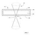
- FIG. 2is a diagram of laser machining a glass substrate used to explain terms used herein;
- FIG. 3is a diagram of laser machining a glass substrate according to an implementation of the teachings herein;
- FIG. 4is a photograph of examples of glass laser machining internal features according to an implementation of the teachings herein;
- FIGS. 5A-5Dare close-up photographs of details of glass including laser machined features according to an implementation of the teachings herein.
- strengthened glassalso referred to as tempered glass herein
- tempered glasshas advantages for a variety of applications including portable computing devices such as mobile phones, tablet computers, media players and laptop computer displays, for example.
- Substrates of silicon-based glasscan be strengthened by exposing the surfaces of a glass sheet to certain chemicals. For example, immersing certain types of glass in potassium salts can result in a process that replaces sodium with larger potassium atoms at the surface of the glass, resulting in deformations that put portions of the glass on and near the surface into compression and leave the interior of the glass sheet in tension.
- strengthened glasscan cause problems with traditional mechanical glass cutting techniques that use saws or blades.
- Laser machiningcan replace traditional saws and blades for making linear cuts in strengthened glass substrates, however, efficiently laser machining internal features in strengthened glass substrates can be difficult due to problems with small curved feature shapes, kerf sidewall taper and cracking of the substrate.
- the compression of strengthened glasscan exceed 600 MPa in regions at and near the surface of the glass.
- the interior regions of strengthened glasscan be under tension exceeding 90 MPa.
- 700 ⁇ m thick strengthened glass substratescan have an inner tension of about 40 MPA while 400 ⁇ m thick strengthened glass substrates can have an inner tension of about 91 MPa.
- An internal featurecan be defined as a feature laser machined in a strengthened glass substrate where material is removed between a top surface of the substrate and a bottom surface of the substrate without reaching an edge of the substrate.
- the laser machined featurecan include a blank in the interior of the feature that is separated from the substrate by the laser machining process and can be readily removed to provide an open feature in the substrate.
- a shallow cut or trenchmay be laser machined in a first surface of the glass sheet or substrate.
- the trench in the first or top surface of the substratecan be formed by directing a beam of laser pulses at a first surface and moving the beam of laser pulses along a path on the surface.
- Undesired cracking of the substratecan be avoided by selecting appropriate laser parameters and by limiting the depth of the trench to the compression region near the surface of the substrate.
- the laser pulsescan be focused through the substrate onto the opposite or second surface of the glass substrate.
- the laser parameterscan be selected to produce pulses at wavelengths and pulse fluences to which the strengthened glass is transparent, thereby permitting the laser beam pulses to be directed through the first surface of the glass substrate, through the interior of the glass substrate to be focused onto or near the second or bottom surface of the glass substrate. Focusing the laser beam pulses in this fashion permits the glass substrate to be laser machined from the substrate surface opposite the direction from which the laser beam pulses impinge the substrate.
- Removing material starting at the bottom surface of the substratepermits the material to be removed in “chips” as discussed in more detail below by selecting laser parameters appropriately. Since the substrate is being laser machined from the bottom up, the chips removed from the substrate to form the kerf can fall harmlessly out of the way as they are separated from the surface. By repeatedly directing the laser beam to a path that describes the kerf, material can be removed to form a through-cut from the bottom surface of the substrate to the top surface. By arranging the trench in the top surface to be outside and proximate to the through-cut kerf, any cracks formed in or near the surface in the compression region will be contained in the small region between the kerf and the trench
- FIG. 1shows a laser processing system 100 that can be used to implement the techniques disclosed herein.
- Laser processing system 100has a laser 102 , which may be a solid state, fiber laser or other laser, and depends on the application.
- Laser 102emits a laser beam 104 that is processed by laser pulse optics 106 , which may be a simple optical component such as a lens or much more complex assemblies containing temporal and spatial beam shaping optics depending upon the laser parameters desired.
- Laser beam 10is then directed by laser steering optics 108 through optional laser field optics 110 to substrate 112 .
- Substrate 112is supported on a chuck 114 attached to motion stages 116 .
- motion stages 116are controlled by an x-axis linear motor 118 , a y-axis linear motor 120 and a z-axis motor 115 .
- Laser processing system 100can use z-axis motor 115 to move chuck 114 relative to laser field optics 110 to position the focal spot of laser beam 100 at different positions relative to substrate 112 .
- laser processing system 100may include z-axis control as a part of steering optics 108 or laser field optics 110 to position the focal spot of laser beam 100 with respect to workpiece 112 through either moving the optics or adjusting the optics to re-focus laser 102 .
- Controller 122controls laser 102 , laser pulse optics 106 , steering optics 108 and motion stages 116 through linear motors 118 , 120 to direct laser beam 104 to workpiece or substrate 112 .
- Controller 122can be any controller, for example, a microcontroller that includes a central processing unit (CPU), random access memory (RAM), read only memory (ROM) and input/output ports receiving input signals and sending command signals to these components.
- the command signalsare generally output based on programming instructions stored in memory, and the functions of each of the programming instructions are performed by the logic of the CPU.
- Various componentscould include their own controllers that transmit data to and from controller 122 as a main controller along a communication path.
- controller 122could be incorporated into a computer, such as a personal computer. Controller 122 could also be implemented by one or more microprocessors using external memory.
- y-axis linear motor 120moves chuck 114 along rails (not shown) oriented along the y-axis to make a scribe line as discussed in more detail hereinafter.
- x-axis linear motor 118would move chuck 114 and the motion stage including the rails along a second set of rails (not shown) oriented along the x-axis.
- laser field optics 110 and optionally laser 102 , laser pulse optics 106 and/or steering optics 108could be mounted in a head movable along one of the x-axis and the y-axis (and optionally the z-axis), while a single motion stage 116 is configured to move in the other of the x-axis and the y-axis using, for example, a linear motor moving chuck 114 along rails.
- Another optionis to mount a head supporting laser field optics 110 and optionally laser 102 , laser pulse optics 106 and/or laser beam steering optics 108 so that the head is movable along each of the x-axis and the y-axis (and optionally the z-axis), while chuck 114 is mounted on a fixed base. Rotational movement can also be included in laser processing system 100 .
- Laser beam steering optics 108generally includes galvanometers, fast steering mirrors, piezo-electric devices, electro-optical modulators, acousto-optical modulators and the like. Beam positioning equipment such as beam steering optics 108 can provide relatively fast positioning.
- beam steering optics 108can include two galvanometer-based scanners, commonly called “galvos,” arranged one each on the x- and y-axes. Each galvo includes three main components—the galvanometer, a mirror (or mirrors) and a servo driver board that controls the system. The galvos may be arranged along a respective axis and rotate their respective mirror(s) at a high speed from side to side, instead of spinning continuously in one direction, thus providing a side-to-side laser path, for example.
- a laser beamis the volume that laser pulses describe as they are emitted from the laser and travel through the laser optics or free space to a target or workpiece.
- the laser beamcan be defined as the envelope within which the laser pulses maintain at least certain energy as they pass.
- a pulsed laser beam 202is applied to a strengthened glass sheet or substrate 200 .
- the portion of laser beam 202 that is focused down to the smallest cross-sectional areacan be called the focal spot 212 .
- As laser beam 202 approaches and leaves focal spot 212it can form a beam waist 214 proximate to focal spot 212 as the path of laser beam 202 narrows and widens.
- the fluenceor energy per unit area (e.g., measured in Joules/cm 2 ) increases due to the decreasing cross-sectional area laser beam 202 travels through.
- the fluencereaches a maximum as laser beam 202 passes through focal spot 212 and then decreases as laser beam 202 leaves focal spot 212 via beam waist 214 .
- a kerfmay be laser machined from the top to bottom surface.
- debris formed by such machiningcan collect in the kerf as it is being formed.
- Debris in a kerfcan absorb and re-transmit thermal energy to, thereby slowing machining rates and potentially causing heat associated flaws such as cracking due to thermal transmission from the debris.
- laser machiningmay be performed from the bottom up.
- Laser beam 202is directed by a laser processing system, such as laser processing system 100 , through the top or first surface 204 of strengthened glass substrate 200 , through a compression region 208 and a tension region 210 , through compression region 208 again and then exits strengthened glass substrate 200 through the bottom or second surface 206 .
- Focal spot 212 of beam waist 214can be positioned using z-axis motor 115 or by re-focusing laser beam 202 , for example, at or near bottom or second surface 206 of strengthened glass substrate 200 .
- transparency of a material to laser pulsescan be a function of wavelength and fluence.
- laser pulsescan be positioned so that the chips caused by each pulse of the laser beam are combine to form a kerf wider and longer than a single chip.
- a kerf of the desired dimensions and shapecan be produced so as to machine the kerf completely through the strengthened glass substrate from the bottom surface to the top.
- laser machining strengthened glass substratescan cause rapid and uncontrolled cracking in the inner tension region as cracks created by the laser machining process propagate from a compression region to the inner tension region.
- aspects of disclosed implementationsavoid rapid and uncontrolled cracking as a result of adjusting the laser parameters to remove material from the strengthened glass substrate by “chipping” material from a surface of the substrate.
- a thin, laser spot-sized chip of materialhaving a diameter approximately equal to the focal spot size and about one or two microns thick is removed from the surface of the strengthened glass substrate by a single picosecond laser pulse. As each chip is removed from the substrate, a substantial portion of the residual thermal energy remaining in the substrate after the pulse fractures the chip from the surface is carried away with the chip, thereby preventing heat transfer to adjacent regions.
- FIG. 3is a cross-sectional view of a strengthened glass substrate 300 showing laser machining according to aspects of disclosed implementations.
- FIG. 3shows a strengthened glass substrate 300 having compression regions 303 , 305 adjacent each of a top surface 302 and a bottom surface 306 .
- Dotted lines 304 , 308respectively indicate depths of compression regions 303 , 305 below surfaces 302 , 306 . Between dotted lines 304 , 308 there can be an interior region 310 that is under tension.
- the first step in the process of laser machining interior features in a strengthened glass plate 300can include laser machining a trench 312 in compression region 303 of top surface 302 .
- Trench 312may be machined by focusing the beam waist of the laser pulses at or near top surface 302 and moving the laser pulses along a path on top surface 302 of substrate 300 at a selected scan velocity, using steering optics 108 , motion stages 116 or a combination of steering optics 108 and motion stages 116 in response to commands from controller 122 , for example.
- the laser beam pulse parameterscan be adjusted to form trench 312 so that trench 312 is about as wide as the focal spot and extends several microns into top surface 302 with a mean path radius of D 1 .
- the laser beam parameterscan be adjusted to permit trench 312 to be laser machined without penetrating beyond compression region 303 into interior tension region 310 . Confining trench 312 to compression region 303 prevents uncontrolled crack propagation in interior tension region 310 that could lead to eventual part failure.
- Laser parameters that can be selected to produce the desired level of material removal while avoiding crackinginclude laser wavelength, laser power, pulse duration, pulse energy, focal spot size, pulse repetition rate, polarization and scan velocity.
- laser parameters that can be used to laser machine strengthened glass substratesinclude a wavelength between 266 nm and 1064 nm, laser power of between 1 watt and 50 watts, a pulse duration between 1 femtosecond and 100 nanoseconds, a pulse energy between 1 ⁇ J and 100 ⁇ A at the work surface, a spot size between 1 ⁇ m and 100 ⁇ m, a pulse repetition rate between 100 kHz and 10 MHz, circular polarization and a scan velocity between 1,000 mm/s and 100,000 mm/s.
- the laser parametersinclude a wavelength of about 515 nm, laser power between about 6.2 watts and 14.5 watts, a pulse duration of about 27 ps, a pulse energy at the work surface of about 14.5 ⁇ J, a spot size of about 12 ⁇ m, a pulse repetition rate between 100 kHz and 10 MHz, and a scan velocity between about 2,000 mm/s and 10,000 mm/s.
- Laser pulse parametersare desirably selected to couple enough energy per pulse to cause a microscopic “chip” of material as described previously to separate from the surface without causing cracks in the adjacent material.
- chips produced by the laser pulsescan be about the same area as the focal spot size of the laser pulses with a thickness of one or two microns.
- the focal spot sizei.e., diameter
- the laser pulsesBy positioning the laser pulses with respect to a surface of substrate 300 , material can be removed over a desired area to a desired depth by repeated laser pulses. This material removal process can be influenced by the polarization state of the laser beam.
- An implementation of the teachings hereincan circularly polarize the laser beam to improve the uniformity of material removal, for example. Other types of polarization including linear or elliptical polarization can also be used.
- the laser processing systempositions the focal spot of the laser pulses at or beneath bottom surface 306 of strengthened glass substrate 300 to form a kerf 320 by removing material starting at the bottom surface 306 and ending at the top surface 302 .
- kerf 320can be formed by directing one laser pulse or a group of individual laser pulses in the direction along width ⁇ as described below to remove one or two microns of material as chips starting at bottom surface 306 along the entire closed path and then repeating the process while raising the z-height of the focal spot to position the focal spot with respect to the surface being machined.
- the focal spotmay be moved using a z-motion stage to move substrate 300 relative to the laser (e.g., using z-axis motor 115 ) or the laser relative to substrate 300 so that the focal spot moves relative to the processing surface of substrate 300 .
- control of the lasermay be changed to adjust the focal spot position without changing the diameter or requiring mechanical z-axis movement.
- a group of individual laser pulsesthey may be formed by a plurality of lasers arranged so that their beams are applied in a straight or curved line or in some regular pattern such as a hexagonal packed arrangement.
- the laser pulse parameters usedmay be similar to those described above. Appropriate selection of laser parameters can permit the unfocused laser pulses to pass through strengthened glass substrate 300 without damage yet have enough energy to ablate strengthened glass substrate 300 at locations where the focal spot intersects or is proximate to substrate 300 . Each new position of the focal spot corresponds or nearly corresponds to the current surface being machined as kerf 320 extends from the initial machining surface, bottom surface 306 .
- Laser machining kerf 320proceeds by removing material from the bottom to the top of the substrate 300 while following a closed path around the internal feature being machined. Assuming that a radius D 2 has been selected for a particular internal feature, which would be round in the example of FIG. 3 , a width ⁇ for the through-cut can be selected that provides clean removal of the resulting internal blank 318 so that only the internal feature is left. Once width ⁇ is selected, the number of kerf passes or paths of laser pulses required to remove this material can be calculated by dividing width ⁇ of the through-cut by the laser spot size minus the overlap between passes, referred to as the kerf step.
- the laser pulses that create chips to extend the kerfcan cause some degree of cracking as top surface 302 is exposed to energy from below. Cracks formed by the laser pulses in or near top surface 302 can be contained in the region between the outer edge 314 of the through-cut and trench 312 , thereby preventing uncontrolled propagation of cracks in top surface 302 . Cracks occurring in blank 318 can be discarded along with blank 318 .
- the two-step processmay be used to generate the internal feature as the resulting product. That is, instead of discarding the central cut out portion as a blank, the outer portion may be considered to be the undesirable portion so that a smooth outer edge is generated for the resulting product formed of the internal feature. This would involve forming groove or trench 312 to the inside of the feature as opposed to the outside as shown in FIG. 3 .
- FIG. 4shows examples of internal features machined in strengthened glass substrates 400 A- 400 D.
- FIG. 4shows 10 mm squares 402 with rounded corners (with a 2 mm radius) machined in substrate 400 A, 10 mm circles 404 machined in substrate 400 B, 10 mm ⁇ 1 mm slots 406 with 0.5 mm radius at the corners machined in substrate 400 C, and 1 mm circles 408 machined in substrate 400 D.
- a property of internal featuresis that in cases where an internal blank is created as a result of the machining, the internal blank can be discarded. Therefore, any cracks that occur in the internal blank can be disregarded.
- an internal blank 410 for one of 10 mm squares 402 and an internal blank 412 for one of 10 mm circles 404are shown.
- substrates 400 A- 400 Dare each 0.7 mm thick and made of strengthened glass having a first Central Tension (C.T.) value. For 120 cut features, yield was 100%. The cutting speed was about 1.7 mm/s for squares 402 , circles 404 and slots 406 , but circles 408 required a slower speed due to the limitations of the scan head used. In another example, substrates 400 A- 400 D are each 0.4 mm thick and made of strengthened glass having a second C.T. value higher than the first C.T. value. For 120 cut features, yield was 100%. The cutting speed was about 2.38 mm/s for squares 402 , circles 404 and slots 406 , but again circles 408 required a slower speed due to the limitations of the scan head used.
- C.T.Central Tension
- FIGS. 5A-5Dare photographs of a 1 mm round hole laser machined in a strengthened glass substrate according to aspects of disclosed implementations.
- FIG. 5Ais a photograph of a top surface showing an edge of the hole.
- FIG. 5Bshows the same edge taken from the associated bottom surface.
- FIG. 5Cis a photograph of the entire 1 mm hole taken from the top surface at a lower resolution than those in FIGS. 5A and 5B .
- FIG. 5Dis a photograph of the same hole as that in FIG. 7C taken from the bottom surface. Note that all of the edges appear intact, smooth and uncracked. The dark areas near edges are shadows.
- a first step of laser scribingforms one or more shallow grooves in a top surface of a sheet of strengthened glass along a closed path forming a shape of a desired cut out (also called an internal feature). Then, the laser is focused onto the bottom of the strengthened glass so that the glass is cut from the bottom to the top by refocusing the laser with the cut line using direct ablation. Cracks and chipping are confined by the grooves so that very good edge quality without chipping may be achieved.
- the cuttingcan occur at relatively high speeds and can be used with features as small as several hundred microns. Glass sheets ranging in thickness from 1 mm to 10 mm were tested and resulted in a 100% yield (that is, no loss of product due to cracking or chipping).
Landscapes
- Engineering & Computer Science (AREA)
- Chemical & Material Sciences (AREA)
- Physics & Mathematics (AREA)
- Optics & Photonics (AREA)
- Organic Chemistry (AREA)
- Materials Engineering (AREA)
- Plasma & Fusion (AREA)
- Mechanical Engineering (AREA)
- Health & Medical Sciences (AREA)
- Toxicology (AREA)
- Thermal Sciences (AREA)
- Laser Beam Processing (AREA)
- Re-Forming, After-Treatment, Cutting And Transporting Of Glass Products (AREA)
Abstract
Description
a(σf)=(2γE)/(πσf2); wherein (1)
σfis the applied stress;
γ is the surface energy density for glass; and
Δ=Kerf Step×Kerf Passes (2)
Radius D2 of the desired internal feature can be calculated from the radius D1 of the through-cut by the equation:
D1=D2+Δ+N×Kerf Step (3)
where N is an integer that can assume a value between 1 and 3, for example. Assuming a 10 μm focal spot size and a value of N=2, this equation yields a distance D3 between the
Claims (18)
Priority Applications (5)
| Application Number | Priority Date | Filing Date | Title |
|---|---|---|---|
| US14/229,347US9776906B2 (en) | 2014-03-28 | 2014-03-28 | Laser machining strengthened glass |
| TW104108240ATW201536708A (en) | 2014-03-28 | 2015-03-16 | Laser machining strengthened glass |
| JP2015058977AJP2015189667A (en) | 2014-03-28 | 2015-03-23 | Method for laser machining strengthened glass |
| CN201510134013.2ACN104944756A (en) | 2014-03-28 | 2015-03-25 | Laser machining strengthened glass |
| KR1020150042350AKR20150112870A (en) | 2014-03-28 | 2015-03-26 | Laser machining strengthened glass |
Applications Claiming Priority (1)
| Application Number | Priority Date | Filing Date | Title |
|---|---|---|---|
| US14/229,347US9776906B2 (en) | 2014-03-28 | 2014-03-28 | Laser machining strengthened glass |
Publications (2)
| Publication Number | Publication Date |
|---|---|
| US20150274574A1 US20150274574A1 (en) | 2015-10-01 |
| US9776906B2true US9776906B2 (en) | 2017-10-03 |
Family
ID=54159896
Family Applications (1)
| Application Number | Title | Priority Date | Filing Date |
|---|---|---|---|
| US14/229,347Expired - Fee RelatedUS9776906B2 (en) | 2014-03-28 | 2014-03-28 | Laser machining strengthened glass |
Country Status (5)
| Country | Link |
|---|---|
| US (1) | US9776906B2 (en) |
| JP (1) | JP2015189667A (en) |
| KR (1) | KR20150112870A (en) |
| CN (1) | CN104944756A (en) |
| TW (1) | TW201536708A (en) |
Families Citing this family (9)
| Publication number | Priority date | Publication date | Assignee | Title |
|---|---|---|---|---|
| KR20140138134A (en) | 2012-02-28 | 2014-12-03 | 일렉트로 싸이언티픽 인더스트리이즈 인코포레이티드 | Method and apparatus for separation of strengthened glass and articles produced thereby |
| US9809485B2 (en)* | 2015-11-02 | 2017-11-07 | Glasstech, Inc. | Lift device for a glass processing system |
| KR20190129914A (en)* | 2017-03-31 | 2019-11-20 | 미쓰보시 다이야몬도 고교 가부시키가이샤 | Scribe processing method and scribe processing equipment |
| US11401195B2 (en)* | 2018-03-29 | 2022-08-02 | Corning Incorporated | Selective laser processing of transparent workpiece stacks |
| JP6602933B2 (en)* | 2018-10-17 | 2019-11-06 | デクセリアルズ株式会社 | Photocurable resin composition and method for manufacturing image display device |
| EP4025377A1 (en) | 2019-09-06 | 2022-07-13 | Cericom GmbH | Method and device for introducing a cut in a workpiece |
| CN111718113B (en)* | 2020-06-28 | 2024-04-19 | 深圳泰德激光技术股份有限公司 | Glass cutting apparatus |
| DE102021105034A1 (en) | 2021-03-02 | 2022-09-08 | Cericom GmbH | Device and method for processing a workpiece made of glass |
| DE102022131535A1 (en)* | 2022-11-29 | 2024-05-29 | Trumpf Laser- Und Systemtechnik Gmbh | Method and device for laser processing of a glass element |
Citations (68)
| Publication number | Priority date | Publication date | Assignee | Title |
|---|---|---|---|---|
| US4702042A (en) | 1984-09-27 | 1987-10-27 | Libbey-Owens-Ford Co. | Cutting strengthened glass |
| US4828900A (en) | 1987-12-23 | 1989-05-09 | Ppg Industries, Inc. | Discrete glass cutting and edge shaping |
| US5413664A (en) | 1990-05-09 | 1995-05-09 | Canon Kabushiki Kaisha | Apparatus for preparing a semiconductor device, photo treatment apparatus, pattern forming apparatus and fabrication apparatus |
| US5826772A (en) | 1995-08-31 | 1998-10-27 | Corning Incorporated | Method and apparatus for breaking brittle materials |
| JPH11163403A (en) | 1997-11-28 | 1999-06-18 | Nichia Chem Ind Ltd | Method for manufacturing nitride semiconductor device |
| US5973290A (en) | 1997-02-26 | 1999-10-26 | W. L. Gore & Associates, Inc. | Laser apparatus having improved via processing rate |
| US20010035447A1 (en) | 2000-05-05 | 2001-11-01 | Andreas Gartner | Methods for laser cut initiation |
| US20020041946A1 (en) | 2000-08-18 | 2002-04-11 | Nippon Sheet Glass Co., Ltd. | Process for cutting a glass sheet and a glass disk for a recording medium |
| JP2002192369A (en) | 2000-09-13 | 2002-07-10 | Hamamatsu Photonics Kk | Laser beam machining method and laser beam machining device |
| JP2002308637A (en) | 2001-04-04 | 2002-10-23 | Sony Corp | Method and apparatus for manufacturing glass substrate |
| US6642477B1 (en) | 2001-10-23 | 2003-11-04 | Imra America, Inc. | Method for laser drilling a counter-tapered through-hole in a material |
| US6809291B1 (en) | 2002-08-30 | 2004-10-26 | Southeastern Universities Research Assn., Inc. | Process for laser machining and surface treatment |
| JP2004299969A (en) | 2003-03-31 | 2004-10-28 | Toshiba Ceramics Co Ltd | How to slice silica glass |
| US6820330B1 (en) | 1996-12-13 | 2004-11-23 | Tessera, Inc. | Method for forming a multi-layer circuit assembly |
| US20050042805A1 (en) | 2003-07-11 | 2005-02-24 | Swenson Edward J. | Method of forming a scribe line on a passive electronic component substrate |
| CN1657220A (en) | 2004-02-19 | 2005-08-24 | 佳能株式会社 | Laser based splitting method, object to be split, and semiconductor element chip |
| US20050221044A1 (en) | 2002-05-07 | 2005-10-06 | Saint-Gobain Glass France | Glass cutting method which does not involve breaking |
| US6962279B1 (en) | 2000-10-18 | 2005-11-08 | Ge Medical Systems Global Technology Company, Llc | Apparatus and method for glass separation for flat panel displays |
| US6992026B2 (en) | 2000-09-13 | 2006-01-31 | Hamamatsu Photonics K.K. | Laser processing method and laser processing apparatus |
| US20060021978A1 (en) | 2002-02-21 | 2006-02-02 | Alexeev Andrey M | Method for cutting non-metallic materials and device for carring out said method |
| DE10029110B4 (en) | 1999-06-15 | 2006-05-18 | Fraunhofer-Gesellschaft zur Förderung der angewandten Forschung e.V. | Method for material processing and use thereof |
| JP2007283318A (en) | 2006-04-13 | 2007-11-01 | Seiko Epson Corp | Substrate manufacturing method, laser processing device, display device, electro-optical device, electronic device |
| US20070262464A1 (en) | 2004-08-24 | 2007-11-15 | Micron Technology, Inc. | Method of forming vias in semiconductor substrates and resulting structures |
| JP2007319881A (en) | 2006-05-31 | 2007-12-13 | Seiko Epson Corp | Substrate manufacturing method, laser processing device, display device, electro-optical device, electronic device |
| US20070291496A1 (en) | 2006-06-02 | 2007-12-20 | Electro Scientific Industries, Inc. | Process for optically transparent via filling |
| US7378342B2 (en) | 2004-08-27 | 2008-05-27 | Micron Technology, Inc. | Methods for forming vias varying lateral dimensions |
| US20080128953A1 (en) | 2003-05-19 | 2008-06-05 | Yusuke Nagai | Workpiece dividing method utilizing laser beam |
| US20080185367A1 (en) | 2007-02-01 | 2008-08-07 | Uri El-Hanany | Method and system of machining using a beam of photons |
| DE102007009786A1 (en) | 2007-02-27 | 2008-08-28 | Schott Ag | Process to surface harden a glass panel whose material contains sodium by treatment with potassium nitrate |
| US20080283509A1 (en) | 2007-05-15 | 2008-11-20 | Anatoli Anatolyevich Abramov | Method and apparatus for scoring and separating a brittle material with a single beam of radiation |
| JP2009061462A (en) | 2007-09-05 | 2009-03-26 | Sumitomo Electric Ind Ltd | Substrate manufacturing method and substrate |
| US20090201444A1 (en) | 2001-11-08 | 2009-08-13 | Koji Yamabuchi | Method and apparatus for cutting apart a glass substrate, liquid crystal panel, and apparatus for fabricating a liquid crystal panel |
| EP2096375A1 (en) | 2008-02-26 | 2009-09-02 | Rioglass Solar, S.A. | A reflector element for a solar heat reflector and the method for producing the same |
| JP2009280452A (en) | 2008-05-23 | 2009-12-03 | Central Glass Co Ltd | Glass substrate and method for producing the same |
| KR20100031462A (en) | 2008-09-12 | 2010-03-22 | 오므론 가부시키가이샤 | Forming method and device of scribing-line for cutting |
| US20100147813A1 (en) | 2008-12-17 | 2010-06-17 | Electro Scientific Industries, Inc. | Method for laser processing glass with a chamfered edge |
| US20100206008A1 (en) | 2009-02-19 | 2010-08-19 | Harvey Daniel R | Method of separating strengthened glass |
| US20100221583A1 (en) | 2009-02-27 | 2010-09-02 | Applied Materials, Inc. | Hdd pattern implant system |
| US20100291353A1 (en) | 2009-02-19 | 2010-11-18 | Matthew John Dejneka | Method of separating strengthened glass |
| US20110003619A1 (en) | 2007-12-18 | 2011-01-06 | Hoya Corporation | Cover glass for mobile terminals, manufacturing method of the same and mobile terminal device |
| US20110049765A1 (en)* | 2009-08-28 | 2011-03-03 | Xinghua Li | Methods for Laser Cutting Glass Substrates |
| WO2011025908A1 (en) | 2009-08-28 | 2011-03-03 | Corning Incorporated | Methods for laser cutting articles from chemically strengthened glass substrates |
| JP2011088179A (en) | 2009-10-22 | 2011-05-06 | V Technology Co Ltd | Laser beam machining apparatus |
| US20110124147A1 (en)* | 2009-05-20 | 2011-05-26 | Rofin-Baasel Lasertech Gmbh & Co. Kg | Method for separating silicon solar cells |
| US20110127242A1 (en) | 2009-11-30 | 2011-06-02 | Xinghua Li | Methods for laser scribing and separating glass substrates |
| US20110127244A1 (en) | 2009-11-30 | 2011-06-02 | Xinghua Li | Methods for laser scribing and separating glass substrates |
| JP2011164508A (en) | 2010-02-15 | 2011-08-25 | Sony Corp | Method for manufacturing electric solid-state device, and electric solid-state device |
| US20110226832A1 (en) | 2010-03-19 | 2011-09-22 | John Frederick Bayne | Mechanical scoring and separation of strengthened glass |
| EP2371778A1 (en) | 2010-03-30 | 2011-10-05 | Linde Aktiengesellschaft | Method for producing toughened flat glass with anti-reflective properties |
| JP2011230940A (en) | 2010-04-26 | 2011-11-17 | Mitsuboshi Diamond Industrial Co Ltd | Cutting method for brittle material substrate |
| US8075999B2 (en) | 2008-08-08 | 2011-12-13 | Corning Incorporated | Strengthened glass articles and methods of making |
| JP2011251879A (en) | 2010-06-02 | 2011-12-15 | Asahi Glass Co Ltd | Method and device for cutting chemically strengthened glass |
| US20110318996A1 (en) | 2010-06-28 | 2011-12-29 | Shin-Etsu Chemical Co., Ltd. | Method for manufacturing electronic grade synthetic quartz glass substrate |
| KR20120015366A (en) | 2010-07-19 | 2012-02-21 | 엘지디스플레이 주식회사 | Tempered glass cutting method and cutting device |
| US20120052252A1 (en) | 2010-08-26 | 2012-03-01 | Jeffrey Todd Kohli | Methods for extracting strengthened glass substrates from glass sheets |
| US20120135177A1 (en) | 2010-11-30 | 2012-05-31 | Cornejo Ivan A | Methods for forming grooves and separating strengthened glass substrate sheets |
| US20120135195A1 (en) | 2010-11-30 | 2012-05-31 | Gregory Scott Glaesemann | Methods for separating glass articles from strengthened glass substrate sheets |
| US20120168412A1 (en) | 2011-01-05 | 2012-07-05 | Electro Scientific Industries, Inc | Apparatus and method for forming an aperture in a substrate |
| US20120196071A1 (en) | 2011-02-01 | 2012-08-02 | Cornejo Ivan A | Strengthened glass substrate sheets and methods for fabricating glass panels from glass substrate sheets |
| US20120211923A1 (en) | 2011-02-18 | 2012-08-23 | Sean Matthew Garner | Laser cutting method |
| US8383983B2 (en) | 2009-03-25 | 2013-02-26 | Samsung Display Co., Ltd. | Substrate cutting apparatus and method of cutting substrate using the same |
| US20130155004A1 (en) | 2011-12-16 | 2013-06-20 | Micro Technology Co., Ltd. | Strengthened glass, touch panel and method of manufacturing strengthened glass |
| US20130192305A1 (en) | 2011-08-10 | 2013-08-01 | Matthew L. Black | Methods for separating glass substrate sheets by laser-formed grooves |
| US20130224439A1 (en) | 2012-02-28 | 2013-08-29 | Electro Scientific Industries, Inc. | Method and apparatus for separation of strengthened glass and articles produced thereby |
| US20130221053A1 (en) | 2012-02-28 | 2013-08-29 | Electro Scientific Industries, Inc. | Method and apparatus for separation of strengthened glass and articles produced thereby |
| US8584354B2 (en) | 2010-08-26 | 2013-11-19 | Corning Incorporated | Method for making glass interposer panels |
| US20140093693A1 (en) | 2012-02-28 | 2014-04-03 | Electro Scientific Industries, Inc. | Method and apparatus for separation of strengthened glass and articles produced thereby |
| US20140366456A1 (en)* | 2011-06-22 | 2014-12-18 | Us Synthetic Corporation | Method for laser cutting polycrystalline diamond structures |
- 2014
- 2014-03-28USUS14/229,347patent/US9776906B2/ennot_activeExpired - Fee Related
- 2015
- 2015-03-16TWTW104108240Apatent/TW201536708A/enunknown
- 2015-03-23JPJP2015058977Apatent/JP2015189667A/enactivePending
- 2015-03-25CNCN201510134013.2Apatent/CN104944756A/enactivePending
- 2015-03-26KRKR1020150042350Apatent/KR20150112870A/ennot_activeWithdrawn
Patent Citations (75)
| Publication number | Priority date | Publication date | Assignee | Title |
|---|---|---|---|---|
| US4702042A (en) | 1984-09-27 | 1987-10-27 | Libbey-Owens-Ford Co. | Cutting strengthened glass |
| US4828900A (en) | 1987-12-23 | 1989-05-09 | Ppg Industries, Inc. | Discrete glass cutting and edge shaping |
| EP0321838B1 (en) | 1987-12-23 | 1993-02-24 | Ppg Industries, Inc. | Discrete glass cutting and edge shaping |
| US5413664A (en) | 1990-05-09 | 1995-05-09 | Canon Kabushiki Kaisha | Apparatus for preparing a semiconductor device, photo treatment apparatus, pattern forming apparatus and fabrication apparatus |
| US5826772A (en) | 1995-08-31 | 1998-10-27 | Corning Incorporated | Method and apparatus for breaking brittle materials |
| US6820330B1 (en) | 1996-12-13 | 2004-11-23 | Tessera, Inc. | Method for forming a multi-layer circuit assembly |
| US5973290A (en) | 1997-02-26 | 1999-10-26 | W. L. Gore & Associates, Inc. | Laser apparatus having improved via processing rate |
| JPH11163403A (en) | 1997-11-28 | 1999-06-18 | Nichia Chem Ind Ltd | Method for manufacturing nitride semiconductor device |
| DE10029110B4 (en) | 1999-06-15 | 2006-05-18 | Fraunhofer-Gesellschaft zur Förderung der angewandten Forschung e.V. | Method for material processing and use thereof |
| US20010035447A1 (en) | 2000-05-05 | 2001-11-01 | Andreas Gartner | Methods for laser cut initiation |
| US20020041946A1 (en) | 2000-08-18 | 2002-04-11 | Nippon Sheet Glass Co., Ltd. | Process for cutting a glass sheet and a glass disk for a recording medium |
| US6634186B2 (en) | 2000-08-18 | 2003-10-21 | Nippon Sheet Glass Co., Ltd. | Process for cutting a glass sheet and a glass disk for a recording medium |
| JP2002192369A (en) | 2000-09-13 | 2002-07-10 | Hamamatsu Photonics Kk | Laser beam machining method and laser beam machining device |
| US6992026B2 (en) | 2000-09-13 | 2006-01-31 | Hamamatsu Photonics K.K. | Laser processing method and laser processing apparatus |
| US6962279B1 (en) | 2000-10-18 | 2005-11-08 | Ge Medical Systems Global Technology Company, Llc | Apparatus and method for glass separation for flat panel displays |
| JP2002308637A (en) | 2001-04-04 | 2002-10-23 | Sony Corp | Method and apparatus for manufacturing glass substrate |
| US6642477B1 (en) | 2001-10-23 | 2003-11-04 | Imra America, Inc. | Method for laser drilling a counter-tapered through-hole in a material |
| US20090201444A1 (en) | 2001-11-08 | 2009-08-13 | Koji Yamabuchi | Method and apparatus for cutting apart a glass substrate, liquid crystal panel, and apparatus for fabricating a liquid crystal panel |
| US20060021978A1 (en) | 2002-02-21 | 2006-02-02 | Alexeev Andrey M | Method for cutting non-metallic materials and device for carring out said method |
| US20050221044A1 (en) | 2002-05-07 | 2005-10-06 | Saint-Gobain Glass France | Glass cutting method which does not involve breaking |
| US6809291B1 (en) | 2002-08-30 | 2004-10-26 | Southeastern Universities Research Assn., Inc. | Process for laser machining and surface treatment |
| JP2004299969A (en) | 2003-03-31 | 2004-10-28 | Toshiba Ceramics Co Ltd | How to slice silica glass |
| US20080128953A1 (en) | 2003-05-19 | 2008-06-05 | Yusuke Nagai | Workpiece dividing method utilizing laser beam |
| US20050042805A1 (en) | 2003-07-11 | 2005-02-24 | Swenson Edward J. | Method of forming a scribe line on a passive electronic component substrate |
| CN1657220A (en) | 2004-02-19 | 2005-08-24 | 佳能株式会社 | Laser based splitting method, object to be split, and semiconductor element chip |
| US20070262464A1 (en) | 2004-08-24 | 2007-11-15 | Micron Technology, Inc. | Method of forming vias in semiconductor substrates and resulting structures |
| US7378342B2 (en) | 2004-08-27 | 2008-05-27 | Micron Technology, Inc. | Methods for forming vias varying lateral dimensions |
| JP2007283318A (en) | 2006-04-13 | 2007-11-01 | Seiko Epson Corp | Substrate manufacturing method, laser processing device, display device, electro-optical device, electronic device |
| JP2007319881A (en) | 2006-05-31 | 2007-12-13 | Seiko Epson Corp | Substrate manufacturing method, laser processing device, display device, electro-optical device, electronic device |
| US20070291496A1 (en) | 2006-06-02 | 2007-12-20 | Electro Scientific Industries, Inc. | Process for optically transparent via filling |
| US20080185367A1 (en) | 2007-02-01 | 2008-08-07 | Uri El-Hanany | Method and system of machining using a beam of photons |
| DE102007009786A1 (en) | 2007-02-27 | 2008-08-28 | Schott Ag | Process to surface harden a glass panel whose material contains sodium by treatment with potassium nitrate |
| US20080283509A1 (en) | 2007-05-15 | 2008-11-20 | Anatoli Anatolyevich Abramov | Method and apparatus for scoring and separating a brittle material with a single beam of radiation |
| JP2009061462A (en) | 2007-09-05 | 2009-03-26 | Sumitomo Electric Ind Ltd | Substrate manufacturing method and substrate |
| US20110003619A1 (en) | 2007-12-18 | 2011-01-06 | Hoya Corporation | Cover glass for mobile terminals, manufacturing method of the same and mobile terminal device |
| EP2096375A1 (en) | 2008-02-26 | 2009-09-02 | Rioglass Solar, S.A. | A reflector element for a solar heat reflector and the method for producing the same |
| WO2009106582A2 (en) | 2008-02-26 | 2009-09-03 | Rioglass Solar, S.A. | A reflector element for a solar heat reflector and the method for producing the same |
| JP2009280452A (en) | 2008-05-23 | 2009-12-03 | Central Glass Co Ltd | Glass substrate and method for producing the same |
| US8075999B2 (en) | 2008-08-08 | 2011-12-13 | Corning Incorporated | Strengthened glass articles and methods of making |
| KR20100031462A (en) | 2008-09-12 | 2010-03-22 | 오므론 가부시키가이샤 | Forming method and device of scribing-line for cutting |
| US20100147813A1 (en) | 2008-12-17 | 2010-06-17 | Electro Scientific Industries, Inc. | Method for laser processing glass with a chamfered edge |
| US20100206008A1 (en) | 2009-02-19 | 2010-08-19 | Harvey Daniel R | Method of separating strengthened glass |
| WO2010096359A1 (en) | 2009-02-19 | 2010-08-26 | Corning Incorporated | Method of separating strengthened glass |
| US20100291353A1 (en) | 2009-02-19 | 2010-11-18 | Matthew John Dejneka | Method of separating strengthened glass |
| US20100221583A1 (en) | 2009-02-27 | 2010-09-02 | Applied Materials, Inc. | Hdd pattern implant system |
| US8383983B2 (en) | 2009-03-25 | 2013-02-26 | Samsung Display Co., Ltd. | Substrate cutting apparatus and method of cutting substrate using the same |
| US20110124147A1 (en)* | 2009-05-20 | 2011-05-26 | Rofin-Baasel Lasertech Gmbh & Co. Kg | Method for separating silicon solar cells |
| US20120145331A1 (en) | 2009-08-28 | 2012-06-14 | Kior, Inc, | Methods for laser cutting articles from ion exchanged glass substrates |
| WO2011025903A1 (en) | 2009-08-28 | 2011-03-03 | Corning Incorporated | Methods for laser cutting glass substrates |
| WO2011025908A1 (en) | 2009-08-28 | 2011-03-03 | Corning Incorporated | Methods for laser cutting articles from chemically strengthened glass substrates |
| US20110049765A1 (en)* | 2009-08-28 | 2011-03-03 | Xinghua Li | Methods for Laser Cutting Glass Substrates |
| JP2011088179A (en) | 2009-10-22 | 2011-05-06 | V Technology Co Ltd | Laser beam machining apparatus |
| US20110127242A1 (en) | 2009-11-30 | 2011-06-02 | Xinghua Li | Methods for laser scribing and separating glass substrates |
| US20110127244A1 (en) | 2009-11-30 | 2011-06-02 | Xinghua Li | Methods for laser scribing and separating glass substrates |
| JP2011164508A (en) | 2010-02-15 | 2011-08-25 | Sony Corp | Method for manufacturing electric solid-state device, and electric solid-state device |
| US20110226832A1 (en) | 2010-03-19 | 2011-09-22 | John Frederick Bayne | Mechanical scoring and separation of strengthened glass |
| EP2371778A1 (en) | 2010-03-30 | 2011-10-05 | Linde Aktiengesellschaft | Method for producing toughened flat glass with anti-reflective properties |
| JP2011230940A (en) | 2010-04-26 | 2011-11-17 | Mitsuboshi Diamond Industrial Co Ltd | Cutting method for brittle material substrate |
| JP2011251879A (en) | 2010-06-02 | 2011-12-15 | Asahi Glass Co Ltd | Method and device for cutting chemically strengthened glass |
| US20110318996A1 (en) | 2010-06-28 | 2011-12-29 | Shin-Etsu Chemical Co., Ltd. | Method for manufacturing electronic grade synthetic quartz glass substrate |
| KR20120015366A (en) | 2010-07-19 | 2012-02-21 | 엘지디스플레이 주식회사 | Tempered glass cutting method and cutting device |
| US20120052252A1 (en) | 2010-08-26 | 2012-03-01 | Jeffrey Todd Kohli | Methods for extracting strengthened glass substrates from glass sheets |
| US8584354B2 (en) | 2010-08-26 | 2013-11-19 | Corning Incorporated | Method for making glass interposer panels |
| US20120135177A1 (en) | 2010-11-30 | 2012-05-31 | Cornejo Ivan A | Methods for forming grooves and separating strengthened glass substrate sheets |
| US20120135195A1 (en) | 2010-11-30 | 2012-05-31 | Gregory Scott Glaesemann | Methods for separating glass articles from strengthened glass substrate sheets |
| US20120168412A1 (en) | 2011-01-05 | 2012-07-05 | Electro Scientific Industries, Inc | Apparatus and method for forming an aperture in a substrate |
| US20120196071A1 (en) | 2011-02-01 | 2012-08-02 | Cornejo Ivan A | Strengthened glass substrate sheets and methods for fabricating glass panels from glass substrate sheets |
| US20120211923A1 (en) | 2011-02-18 | 2012-08-23 | Sean Matthew Garner | Laser cutting method |
| US20140366456A1 (en)* | 2011-06-22 | 2014-12-18 | Us Synthetic Corporation | Method for laser cutting polycrystalline diamond structures |
| US20130192305A1 (en) | 2011-08-10 | 2013-08-01 | Matthew L. Black | Methods for separating glass substrate sheets by laser-formed grooves |
| US8635887B2 (en) | 2011-08-10 | 2014-01-28 | Corning Incorporated | Methods for separating glass substrate sheets by laser-formed grooves |
| US20130155004A1 (en) | 2011-12-16 | 2013-06-20 | Micro Technology Co., Ltd. | Strengthened glass, touch panel and method of manufacturing strengthened glass |
| US20130224439A1 (en) | 2012-02-28 | 2013-08-29 | Electro Scientific Industries, Inc. | Method and apparatus for separation of strengthened glass and articles produced thereby |
| US20130221053A1 (en) | 2012-02-28 | 2013-08-29 | Electro Scientific Industries, Inc. | Method and apparatus for separation of strengthened glass and articles produced thereby |
| US20140093693A1 (en) | 2012-02-28 | 2014-04-03 | Electro Scientific Industries, Inc. | Method and apparatus for separation of strengthened glass and articles produced thereby |
Non-Patent Citations (19)
| Title |
|---|
| Anatoli A. Abramov et al., "Laser Separation of Chemically Strengthened Glass" Physics Procedia 5 (2010), 285-290. |
| Beat Neuenschwander et al., "Processing of Metals and Dielectric Materials with PS-Laserpulses: Results, Strategies, Limitations and Needs" Proc. SPIE 7584, Laser Applications in Microelectronic and Optoelectronic Manufacturing XV, 75840R (Feb. 17, 2010); 14 pages. |
| Bradley Elkins Riley, "Evporative Etching for Non-Contact Glass Scribing Using a Single-Mode Ytterbium Fiber Laser", North Carolina State University, 2007, 96 pages. |
| International Search Report of PCT/US2013/0061212, 5 pages. |
| International Search Report of PCT/US2013/027947, 2 pages. |
| International Search Report of PCT/US2013/028022, 5 pages. |
| J. Zhang et al., "High-Speed Machining of Glass Materials by Laser-Induced Plasma-Assisted Ablation Using a 532-nm Laser", Appl. Phys. A 67, 499-501, 1998. |
| Kunihito Nagayama et al. (2011), "Pulse Laser Ablation by Reflection of Laser Pulse at Interface of Transparent Materials", Lasers-Applications in Science and Industry, Dr Krzysztof Jakubczak (Ed.), ISBN: 978-953-307-755-0, InTech, Available from: http://www.intechopen.com/books/lasers-applications-in-science-and-industry/pulse-laser-ablation-byreflection-of-laser-pulse-at-interface-of-transparent-materials. |
| Kunihito Nagayama et al. (2011), "Pulse Laser Ablation by Reflection of Laser Pulse at Interface of Transparent Materials", Lasers—Applications in Science and Industry, Dr Krzysztof Jakubczak (Ed.), ISBN: 978-953-307-755-0, InTech, Available from: http://www.intechopen.com/books/lasers-applications-in-science-and-industry/pulse-laser-ablation-byreflection-of-laser-pulse-at-interface-of-transparent-materials. |
| Lawrence Shah et al., "Femtosecond Laser Deep Hole Drilling of Silicate Glasses in Air", applied Surface Science, 2001, p. 151-164. |
| Loeschner, U., et al. "Micromachining of glass with short ns-pulses and highly repetitive fs-laser pulses." Proceedings of the ICALEO. 2008. 9 pages. |
| M B Strigin, A N Chudinov, "Laser Processing of Glass by Picosecond Pulses", Quantum Electronics 24 (8) 732-735 (1994). |
| Rabia Qindeel et al., "IR Laser Plasma Interaction With Glass", American Journal of Applied Science 4 (12), 2007, pp. 1009-1015. |
| Rico Böhme, "Laser-Induced Backside Wet Etching of Glasses and Crystals", Nov. 6, 2007, 139 pages. |
| Thomas Paul Dumont, et al., "Laser Interaction With Materials: From Transparent Materials to Thin Films", Swiss Federal Institute of Technology Zurich for the degree of Doctor of Natural Sciences, Diss. ETH No. 16620, year of 2006, 162 Pages. |
| Written Opinion of PCT/US2013/0027947, 5 pages. |
| Written Opinion of PCT/US2013/0061212, 10 pages. |
| Written Opinion of PCT/US2013/028022, 2 pages. |
| Y. Hanada et al., "Laser-Induced Plasma-assisted Ablation (LIPAA): Fundamental and Industrial Applications", High Power Laser Ablation VI, Proc. of SPIE vol. 6261, 626111-1 to -15 (2006). |
Also Published As
| Publication number | Publication date |
|---|---|
| JP2015189667A (en) | 2015-11-02 |
| CN104944756A (en) | 2015-09-30 |
| KR20150112870A (en) | 2015-10-07 |
| TW201536708A (en) | 2015-10-01 |
| US20150274574A1 (en) | 2015-10-01 |
Similar Documents
| Publication | Publication Date | Title |
|---|---|---|
| US9776906B2 (en) | Laser machining strengthened glass | |
| US11819949B2 (en) | Multi-laser system and method for cutting and post-cut processing hard dielectric materials | |
| US10343237B2 (en) | System and method for laser beveling and/or polishing | |
| TWI726909B (en) | Laser processing apparatus, methods of laser-processing workpieces and related arrangements | |
| US11565350B2 (en) | System and method for laser beveling and/or polishing | |
| TW201143947A (en) | Laser machining and scribing systems and methods | |
| JP5432285B2 (en) | Method of laser processing glass into a shape with chamfered edges | |
| JP7146770B2 (en) | Method and system for extending the life of optical components in laser processing equipment | |
| US9764427B2 (en) | Multi-laser system and method for cutting and post-cut processing hard dielectric materials | |
| US20090045179A1 (en) | Method and system for cutting solid materials using short pulsed laser | |
| TW201343296A (en) | Laser scribing system and method with extended depth affectation into a workpiece | |
| US20150158116A1 (en) | Method and apparatus for internally marking a substrate having a rough surface | |
| EP2969372A1 (en) | Coordination of beam angle and workpiece movement for taper control | |
| EP3490750A1 (en) | Laser processing apparatus and methods of laser-processing workpieces | |
| KR101309803B1 (en) | Laser drilling apparatus and laser drilling method | |
| JP2005047290A (en) | Laser machining device | |
| US20210331273A1 (en) | Laser processing apparatus and methods of laser-processing workpieces | |
| CN110818241A (en) | Glass cutting method | |
| Bovatsek et al. | Ultrashort pulse micromachining with the 10-μJ FCPA fiber laser | |
| CN117359130A (en) | Ultrasonic vibration assisted ultrafast laser invisible wafer cutting device and method |
Legal Events
| Date | Code | Title | Description |
|---|---|---|---|
| AS | Assignment | Owner name:ELECTRO SCIENTIFIC INDUSTRIES, INC., OREGON Free format text:ASSIGNMENT OF ASSIGNORS INTEREST;ASSIGNORS:REKOW, MATHEW;ZHOU, YUN;FALLETTO, NICOLAS;SIGNING DATES FROM 20140327 TO 20140328;REEL/FRAME:032572/0797 | |
| STCF | Information on status: patent grant | Free format text:PATENTED CASE | |
| AS | Assignment | Owner name:BARCLAYS BANK PLC, AS COLLATERAL AGENT, NEW YORK Free format text:PATENT SECURITY AGREEMENT (TERM LOAN);ASSIGNORS:ELECTRO SCIENTIFIC INDUSTRIES, INC.;MKS INSTRUMENTS, INC.;NEWPORT CORPORATION;REEL/FRAME:048211/0227 Effective date:20190201 Owner name:BARCLAYS BANK PLC, AS COLLATERAL AGENT, NEW YORK Free format text:PATENT SECURITY AGREEMENT (ABL);ASSIGNORS:ELECTRO SCIENTIFIC INDUSTRIES, INC.;MKS INSTRUMENTS, INC.;NEWPORT CORPORATION;REEL/FRAME:048211/0312 Effective date:20190201 | |
| AS | Assignment | Owner name:BARCLAYS BANK PLC, AS COLLATERAL AGENT, NEW YORK Free format text:CORRECTIVE ASSIGNMENT TO CORRECT THE REMOVE U.S. PATENT NO. 7,919,646 PREVIOUSLY RECORDED ON REEL 048211 FRAME 0227. ASSIGNOR(S) HEREBY CONFIRMS THE PATENT SECURITY AGREEMENT (TERM LOAN);ASSIGNORS:ELECTRO SCIENTIFIC INDUSTRIES, INC.;MKS INSTRUMENTS, INC.;NEWPORT CORPORATION;REEL/FRAME:055006/0492 Effective date:20190201 Owner name:BARCLAYS BANK PLC, AS COLLATERAL AGENT, NEW YORK Free format text:CORRECTIVE ASSIGNMENT TO CORRECT THE REMOVE U.S. PATENT NO.7,919,646 PREVIOUSLY RECORDED ON REEL 048211 FRAME 0312. ASSIGNOR(S) HEREBY CONFIRMS THE PATENT SECURITY AGREEMENT (ABL);ASSIGNORS:ELECTRO SCIENTIFIC INDUSTRIES, INC.;MKS INSTRUMENTS, INC.;NEWPORT CORPORATION;REEL/FRAME:055668/0687 Effective date:20190201 | |
| FEPP | Fee payment procedure | Free format text:MAINTENANCE FEE REMINDER MAILED (ORIGINAL EVENT CODE: REM.); ENTITY STATUS OF PATENT OWNER: LARGE ENTITY | |
| LAPS | Lapse for failure to pay maintenance fees | Free format text:PATENT EXPIRED FOR FAILURE TO PAY MAINTENANCE FEES (ORIGINAL EVENT CODE: EXP.); ENTITY STATUS OF PATENT OWNER: LARGE ENTITY | |
| STCH | Information on status: patent discontinuation | Free format text:PATENT EXPIRED DUE TO NONPAYMENT OF MAINTENANCE FEES UNDER 37 CFR 1.362 | |
| FP | Lapsed due to failure to pay maintenance fee | Effective date:20211003 | |
| AS | Assignment | Owner name:ELECTRO SCIENTIFIC INDUSTRIES, INC., OREGON Free format text:RELEASE BY SECURED PARTY;ASSIGNOR:BARCLAYS BANK PLC;REEL/FRAME:063009/0001 Effective date:20220817 Owner name:NEWPORT CORPORATION, MASSACHUSETTS Free format text:RELEASE BY SECURED PARTY;ASSIGNOR:BARCLAYS BANK PLC;REEL/FRAME:063009/0001 Effective date:20220817 Owner name:MKS INSTRUMENTS, INC., MASSACHUSETTS Free format text:RELEASE BY SECURED PARTY;ASSIGNOR:BARCLAYS BANK PLC;REEL/FRAME:063009/0001 Effective date:20220817 Owner name:ELECTRO SCIENTIFIC INDUSTRIES, INC., OREGON Free format text:RELEASE BY SECURED PARTY;ASSIGNOR:BARCLAYS BANK PLC;REEL/FRAME:062739/0001 Effective date:20220817 Owner name:NEWPORT CORPORATION, MASSACHUSETTS Free format text:RELEASE BY SECURED PARTY;ASSIGNOR:BARCLAYS BANK PLC;REEL/FRAME:062739/0001 Effective date:20220817 Owner name:MKS INSTRUMENTS, INC., MASSACHUSETTS Free format text:RELEASE BY SECURED PARTY;ASSIGNOR:BARCLAYS BANK PLC;REEL/FRAME:062739/0001 Effective date:20220817 |