US9776744B2 - Container sealing device - Google Patents
Container sealing deviceDownload PDFInfo
- Publication number
- US9776744B2 US9776744B2US15/407,985US201715407985AUS9776744B2US 9776744 B2US9776744 B2US 9776744B2US 201715407985 AUS201715407985 AUS 201715407985AUS 9776744 B2US9776744 B2US 9776744B2
- Authority
- US
- United States
- Prior art keywords
- containers
- valve
- fluid
- container
- connector
- Prior art date
- Legal status (The legal status is an assumption and is not a legal conclusion. Google has not performed a legal analysis and makes no representation as to the accuracy of the status listed.)
- Active - Reinstated
Links
Images


Classifications
- B—PERFORMING OPERATIONS; TRANSPORTING
- B65—CONVEYING; PACKING; STORING; HANDLING THIN OR FILAMENTARY MATERIAL
- B65B—MACHINES, APPARATUS OR DEVICES FOR, OR METHODS OF, PACKAGING ARTICLES OR MATERIALS; UNPACKING
- B65B3/00—Packaging plastic material, semiliquids, liquids or mixed solids and liquids, in individual containers or receptacles, e.g. bags, sacks, boxes, cartons, cans, or jars
- B65B3/04—Methods of, or means for, filling the material into the containers or receptacles
- B65B3/17—Methods of, or means for, filling the material into the containers or receptacles for filling valve bags
- A—HUMAN NECESSITIES
- A63—SPORTS; GAMES; AMUSEMENTS
- A63H—TOYS, e.g. TOPS, DOLLS, HOOPS OR BUILDING BLOCKS
- A63H27/00—Toy aircraft; Other flying toys
- A63H27/10—Balloons
- A—HUMAN NECESSITIES
- A63—SPORTS; GAMES; AMUSEMENTS
- A63H—TOYS, e.g. TOPS, DOLLS, HOOPS OR BUILDING BLOCKS
- A63H37/00—Jokes; Confetti, streamers, or other dance favours ; Cracker bonbons or the like
- B—PERFORMING OPERATIONS; TRANSPORTING
- B65—CONVEYING; PACKING; STORING; HANDLING THIN OR FILAMENTARY MATERIAL
- B65B—MACHINES, APPARATUS OR DEVICES FOR, OR METHODS OF, PACKAGING ARTICLES OR MATERIALS; UNPACKING
- B65B7/00—Closing containers or receptacles after filling
- B65B7/02—Closing containers or receptacles deformed by, or taking-up shape, of, contents, e.g. bags, sacks
- B65B7/025—Closing valve bags
- A—HUMAN NECESSITIES
- A63—SPORTS; GAMES; AMUSEMENTS
- A63H—TOYS, e.g. TOPS, DOLLS, HOOPS OR BUILDING BLOCKS
- A63H27/00—Toy aircraft; Other flying toys
- A63H27/10—Balloons
- A63H2027/1033—Inflation devices or methods for inflating balloons
Definitions
- the present applicationgenerally relates to devices, apparatus, systems and methods for filling containers with a fluid. Specifically, the present application relates to automatically filling multiple balloons with a fluid mixture.
- fluid-inflatable containerssuch as balloons
- fluid-inflatable containerscan be difficult to fill with a fluid, especially when there is a need to fill multiple containers simultaneously and/or quickly.
- various productsare currently available that facilitate the filling of fluid-inflatable containers.
- These fluid-inflatable containersmay be filled or inflated using various fluids, such as, e.g., liquids such as water, gases such as helium, or medications.
- fluid-inflatable containersinclude those used for recreational purposes, such as balloons.
- Embodiments of the present inventioncan provide an apparatus for filling a plurality of containers with a fluid.
- the apparatuscan include a connector configured to removably couple the apparatus to a fluid source, a flow path providing fluid communication between the fluid source and a plurality of containers coupled to the apparatus, a sealing element disposed within each of the plurality of containers, the sealing element configured to couple the container to the apparatus and automatically seal the container when the container is decoupled from the apparatus, and a retaining member affixed to each of the plurality of containers to position the sealing element in a neck of each of the plurality of containers.
- the sealing elementcan include a valve.
- the valvecan include a channel and a sealing member.
- the sealing membercan include a flap and/or a first wall of a slit and a second wall of the slit.
- the valvecan include at least one of a reed valve, a duckbill valve, and a bullet valve.
- the retaining memberscan include substantially rigid rings configured to prevent radial expansion of the container.
- the retaining memberscan include a sleeve configured to prevent radial expansion of the container.
- the retaining membercan be affixed to an exterior surface of the container.
- the plurality of containerscan include balloons and the apparatus can be reusable.
- the apparatuscan include a connector configured to removably couple the apparatus to a fluid source, a flow path providing fluid communication between the fluid source and a plurality of containers coupled to the apparatus, a plurality of conduits, and a valve within each of the plurality of containers, the valve including sealing members and a channel through which one of the plurality of conduits is received, the sealing members being configured to be maintained in an open position by the conduit received in the channel while coupled to the apparatus and to automatically seal the container when the container is decoupled from the apparatus.
- the valvecan be positioned in a neck of the container and can include at least one of a reed valve, a duckbill valve, and a bullet valve.
- the apparatuscan also include a retaining member affixed to each of the plurality of containers to position the valve in the neck of each of the plurality of containers.
- the retaining memberscan include substantially rigid rings configured to prevent radial expansion of the container.
- the retaining memberscan include a sleeve configured to prevent radial expansion of the container.
- the retaining memberscan be affixed to an exterior surface of the container.
- the plurality of containerscan include balloons.
- Yet another embodiment of the present inventioncan provide an apparatus for filling a plurality of containers with a fluid.
- the apparatuscan include a connector configured to removably couple the apparatus to a fluid source, a flow path providing fluid communication between the fluid source and a plurality of containers coupled to the apparatus, a plurality of conduits, and a valve within each of the plurality of containers, the valve including sealing members and a channel through which one of the plurality of conduits is received, the sealing members being configured to be maintained in an open position by a flow pressure of the fluid while coupled to the apparatus and to automatically seal the container when the container is decoupled from the apparatus.
- the valvecan be positioned in a neck of the container and can include at least one of a reed valve, a duckbill valve, and a bullet valve.
- the apparatuscan also include a retaining member affixed to each of the plurality of containers to position the valve in the neck of each of the plurality of containers.
- the retaining memberscan include substantially rigid rings configured to prevent radial expansion of the container.
- the retaining memberscan include a sleeve configured to prevent radial expansion of the container.
- the retaining memberscan be affixed to an exterior surface of the container.
- the plurality of containerscan include balloons.
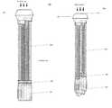
- FIG. 1Ais an illustration of an exemplary fluid filling apparatus according to embodiments of the present invention.
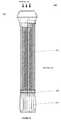
- FIG. 1Bis an illustration of an exemplary fluid filling apparatus according to embodiments of the present invention.
- FIGS. 2A-2Care illustrations of exemplary sealing elements according to embodiments of the present invention.
- FIGS. 3A and 3Bare a perspective views of an exemplary connector according to embodiments of the present invention.
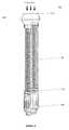
- FIG. 4Ais a cross-sectional view of an exemplary fluid filling apparatus according to embodiments of the present invention.
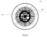
- FIG. 4Bis a top view of an exemplary fluid filling apparatus according to embodiments of the present invention.
- FIG. 5is a flow diagram of an exemplary method according to embodiments of the present invention.
- Embodiments of the present inventionare generally directed to devices, apparatus, systems, and methods for filling containers with a fluid. Specifically, embodiments of the present invention provide an apparatus for filling multiple balloons at substantially the same time. Certain embodiments of the present invention facilitate introducing an additive to a fluid source to enable automatic filling of multiple containers in a substantially simultaneously manner with a fluid mixture. Although the embodiments of the present invention are primarily described with respect to dyes and fluid-inflatable containers, it is not limited thereto, and it should be noted that the apparatus and systems described herein may be used to fill any type of containers with any type of fluid and/or fluid mixture.
- FIG. 1Ashows an exemplary fluid filling apparatus 100 .
- fluid filling apparatus 100may include connector 110 , conduits 130 , containers 150 , and sealing elements 140 .
- fluid filling apparatus 100is coupled to a fluid source, and when the fluid source is activated, the fluid passes through connector 110 , conduits 130 and into containers 150 , thereby filling containers 150 with the fluid at substantially the same time.
- connector 110may include an additive which may mix with the fluid as the fluid is passing through connector 110 so that containers 150 are filled with a mixture of the fluid and the additive.
- the fluid used to fill containers 150may include any type of fluid, such as, water and other liquids, as well as helium and other gases.
- FIG. 1Bshows another embodiment of the present invention.
- certain embodiments of the present inventionprovide a fluid filling apparatus 100 having conduits 130 which are arranged such that the distal end of conduits 130 (e.g., the end of conduit 130 furthest from connector 110 ) are disposed at different distances from a first end 112 of connector 110 .
- each distal endmay be disposed at a respective distance from first end 112 of connector 110 and all the respective distances may be different.
- conduits 130 and containers 150may be arranged in a cascading spiraling arrangement, where the distal end of each conduit 130 is disposed at a different distance from first end 112 of connector 110 .
- conduits 130may take be arranged in any arrangement.
- conduits 130 and containers 150may be arranged in any arrangement or pattern in which the distal end of each conduit 130 is disposed at a different distance from first end 112 of connector 110 .
- conduits 130may be arranged in a sequential arrangement such as, e.g., a zig-zag pattern, a linear pattern, an arcing pattern, a shaped pattern (e.g., a star shape, a moon shape, a rectangle, a square, a circle, a triangle, etc.).
- conduits 130when conduits 130 are arranged in a sequential arrangement, the distance from the distal end of a given conduit 130 to first end 112 of connector 110 may be greater than the distance from the distal end of the preceding conduit to first end 112 of connector 110 . Additionally, although the distal end of conduits 130 are disposed at different distances from a first end 112 of connector 110 , conduits 130 may all be substantially the same length. This may be achieved, for example, by coupling conduits 130 at different distances from first end 112 within connector 110 .
- sealing elements 140may be self-sealing.
- sealing elements 140may automatically seal containers 150 when containers 150 are decoupled from fluid filling apparatus 100 . This may be accomplished when the force that each sealing element 140 exerts in coupling each respective container 150 to fluid filling apparatus 100 is overcome. This may be accomplished, for example, by the weight and/or pressure each container 150 exceeding a certain threshold thereby causing the container to become detached from the conduits 130 , manual removal of the containers 150 , or some other action, such as shaking fluid filling apparatus 100 , to remove containers 150 from fluid filling apparatus 100 . As this force is overcome, the respective container is detached from fluid filling apparatus 100 , and sealing elements 140 automatically seal the end of respective container 150 that was attached to fluid filling apparatus 100 .
- containers 150may include balloons.
- sealing elements 140may include a mechanism by which the containers are automatically sealed when they are detached from fluid filling apparatus 100 .
- sealing elements 140can include rubber bands or clamps, which simply clamp and/or seal the containers by exerting a compressive force around a neck of containers 150 .
- sealing elements 140can include other mechanisms to seal containers 150 .
- sealing elements 140can include a liquid-activated material positioned in the neck of containers 150 that are configured to expand and seal the neck of containers 150 when a fluid such as water is introduced to containers 150 .
- sealing elements 140can include a self-healing membrane positioned in the neck of containers 150 , such as a closed-cell foam, that allow conduits 130 to be inserted there-through, and self-heals when conduit 130 is removed so as to seal container 150 .
- sealing elements 140can also include a valve as shown in FIGS. 2A-2C .
- sealing element 140can include a valve 2000 positioned in the neck of container 150 .
- Valve 2000can include a channel 2002 and a sealing member 2004 , such as a flap.
- conduit 130can be received through channel 2002 to allow fluid to fill container 150 .
- conduit 130can be positioned in channel 2002 such that a portion of conduit 130 extends beyond a lower surface 2006 so that it maintains sealing member 2004 in an open position while conduit 130 is received in channel 2002 .
- conduit 130can be positioned so that it does not extend beyond lower surface 2006 , and sealing member 2004 is opened by the flow pressure of the fluid filling containers 150 as containers 150 are being filled.
- Channel 2002can be sized, shaped, dimensioned, and configured to receive conduit 130 and apply a desired frictional force to ensure that container 150 is coupled to conduit 130 and automatically detaches container 150 from conduit 130 when the weight and/or pressure of container 150 exceeds a certain threshold.
- the shape, length, dimensions of channel 2002can be selected to obtain the desired frictional force.
- the length of the channele.g., the longer the channel the greater the frictional force on conduit 130
- the diameter of the channele.g., a smaller diameter channel would have a greater frictional force
- the shape of the channele.g., cylindrical, rectangular, triangular, oval-shaped, tapered, having ribs, etc.
- the shape of the channele.g., cylindrical, rectangular, triangular, oval-shaped, tapered, having ribs, etc.
- valve 2000is made of silicone.
- valve 2000can be made of other suitable thermoplastics, rubbers, non-thermoplastic rubbers, etc.
- valve 2000can include ring members 2008 and 2010 .
- ring members 2008 and 2010are substantially rigid, and prevent container 150 from radially expanding at the positions where ring members 2008 and 2010 are positioned. This allows valve 2000 to remain positioned in the neck of container 150 so that it cannot be displaced out of container 150 through the opening or into the main body of container 150 as it expands and is filled with fluid.
- ring member 2008 and 2010can be replaced with other mechanisms, components or features that substantially prevent radial expansion of the container, so as to allow valve 2000 to remain positioned in the neck of container 150 , such as, for example, a sleeve, an adhesive, etc.
- valve 2000 shown in FIG. 2Ais a reed type valve mechanism
- sealing elementcan include a duckbill valve 2000 ′ or a bullet valve 2000 ′′ as shown in FIG. 2C .
- Each of duckbill valve 2000 ′ and bullet valve 2000 ′′operates similarly to valve 2000 .
- Each of duckbill valve 2000 ′ and bullet valve 2000 ′′is configured to be positioned in a neck of container 150 and includes a channel ( 2002 ′ and 2002 ′′, respectively) configured to receive conduit 130 therethrough.
- Each of duckbill valve 2000 ′ and bullet valve 2000 ′′also includes a sealing members ( 2004 ′ and 2004 ′′) that seals container 150 .
- sealing members 2004 ′ of duckbill valve 2002 ′can be pressed together to form a seal.
- another embodimentcan provide a valve member including a slit through which conduit 130 is received and the slides/walls of the slit can form a seal when conduit 130 is removed.
- sealing elements 140 including valve 2000can facilitate fluid filling apparatus 100 to be reusable.
- containers 150including sealing elements 140 having valve 2000 already inserted in the neck of containers 150
- fluid filling apparatus 100can be provided preassembled with a certain number of containers 150 . After a user has used all containers 150 that were initial coupled to fluid filling apparatus 100 , replacement containers 150 , including sealing elements 140 including valve 2000 already inserted in the neck of containers 150 , can be provided, and a user can install containers 150 onto conduits 130 of fluid filling apparatus 100 . Accordingly, a user or consumer would not need to purchase the entire fluid filling apparatus 100 again.
- FIGS. 3A and 3Bshow an exemplary connector 110 according to embodiments of the present invention.
- connector 110may be substantially cylindrical and may include a first portion 110 a and a second portion 110 b .
- first portion 110 a and second portion 110 bmay be two distinct components that can be removably or permanently coupled together.
- first portion 110 a and second portion 110 bmay be formed from a single piece.
- connector 110includes coupling element 122 , flow path 124 , and openings/channels 126 .
- Openings/channels 126may include an interior end and an exterior end and provides fluid communication between the exterior of connector 110 and the interior of connector 110 . Further, openings/channels 126 may be dimensioned and sized to receive, or otherwise connect with, conduits 130 .
- Coupling element 122is configured to removably couple connector 110 , and thereby couple fluid filling apparatus 100 , to an upstream component, such as a fluid source. Coupling element 122 may include threads, as shown in FIG. 3A , or any other type of clamping or coupling mechanism.
- connector 110is shown to be substantially cylindrical, connector 110 may take on any shape (e.g., square, rectangular, etc.) that may be desired.
- second portion 110 bmay be an adapter that enables connector 110 to be coupled to different upstream components.
- second portion 110 bmay include various different types of coupling element 122 and may removably couple to first portion 110 a so that connector 110 can be coupled to a variety of upstream components.
- connector 110may include features on the exterior to assist a user in actuating coupling element 122 to couple end cap 120 to an upstream component.
- coupling element 122may include standardized threads for receiving the threads of a standard faucet or hose.
- flow path 124 and openings/channels 126may define a flow path that the fluid may follow from the upstream component, such as a fluid source, through connector 110 to conduits 130 .
- conduits 130are received in or otherwise connected to openings/channels 126 .
- fluid entering connector 110may flow through flow path 124 and through openings/channels 126 to conduits 130 .
- the number and dimensions of the openings/channels 126correspond to the number and dimensions of conduits 130 .
- the number, size, and dimensions of openings/channels 126may be selected in view of the number of containers 150 to be filled at one time and the speed at which they are to be filled.
- connector 110may include any number of openings/channels 126 that is desired.
- FIGS. 3A and 3Baccording to an embodiment of the present invention, connector 110 may include forty openings/channels 126 .
- openings/channels 126may be configured in a spiraling helical arrangement.
- the exterior of connector 110may include a plurality of faceted surfaces 128 in a spiraling helical arrangement.
- the configuration of faceted surfaces 128may correspond to the position of openings/channels 126 so that the exterior end of openings/channels 126 may be disposed on faceted surfaces 128 .
- each faceted surface 128can have any number of openings/channels 126 disposed therein, and each faceted surface 128 could have a different number of openings/channels 126 disposed therein.
- each faceted surface 128could have two openings/channels 126 disposed therein, alternatively, a first stepped surface 128 could have a single opening/channel 126 disposed therein and a second stepped surface could have three openings/channels 126 disposed therein.
- faceted surfaces 128can be arranged in any configuration or arrangement.
- connector 110may not include faceted surfaces 128 and openings/channels 126 may, for example, be disposed in a smooth spiraling helix or in a spiral on a flat exterior surface.
- the interior end of openings/channels 126may also be disposed in a plurality of faceted surfaces disposed in a spiraling helical arrangement in the interior of connector 110 corresponding to the plurality of faceted surfaces 128 disposed on the exterior of connector 110 .
- the interior end of openings/channels 126may disposed on a flat surface within the interior of connector 110 .
- FIG. 4Ashows a cross sectional view of fluid filling apparatus 100 according to embodiments of the present invention.
- connector 110may be substantially cylindrical, and may define a flow path 124 .
- connector 110preferably includes coupling element 122 .
- Coupling element 122may include any type of coupling mechanism, such as, e.g., threads or clamps. Coupling element 122 may be configured to couple connector 110 to an upstream component such as a fluid source.
- coupling element 122may include standardized threads for receiving the threads of a standard faucet or hose. Alternatively, coupling elements 122 may include various other types of coupling mechanisms.
- connector 110is preferably coupled to a fluid source via coupling element 122 .
- the fluid sourceis activated, the fluid travels into connector 110 , through flow path 124 and into each of the openings/channels 126 .
- the fluidthen passes through openings/channels 126 to conduits 130 , which are coupled to openings/channels 126 .
- the fluidthen passes through conduits 130 to fill containers 150 .
- connector 110can include an additive 200 and an additive mixing mechanism.
- additive mixing mechanismmay include a separator 202 which secures additive 200 within the interior of connector 110 and defines two chambers 204 and 206 , which are in fluid communication with each other, within the interior of connector 110 .
- Separator 202secures additive 200 within chamber 206 of the interior of connector 110 during operation of the fluid filling apparatus 100 .
- the fluid sourcewhen activated, the fluid comes into contact with additive 200 in chamber 204 and mixes with additive 200 in chamber 206 and/or chamber 204 .
- the mixture of the additive and the fluidpasses through openings/channels 126 to conduits 130 , which are coupled to openings/channels 126 .
- additive 200may take any form.
- additive 200may be in the form of, e.g., a pellet, a powder, or a gel, and may be any material or substance for which a fluid mixture is desired.
- additive 200may include any substance, such as, e.g., soda ash, bicarbonate, lactose, citric acid, mineral oil, or a dye.
- any number of additivesmay be disposed within chamber 206 of connector 110 .
- FIG. 4Bshows a top-view of connector 110 with the mixing mechanism.
- connector 110includes separator 202 and additives 200 .
- separator 202substantially secures additives 200 to the interior of connector 110 so that additives remain within chamber 206 of connector 110 while fluid filling apparatus 100 is in use.
- separator 202substantially secures additives 200 within chamber 206 of connector 110 even as additives 200 experience turbulence introduced by the fluid flowing through chamber 206 . Accordingly, additives 200 substantially remain within chamber 206 while ensuring that chambers 204 and 206 remain in fluid communication with each other. It is contemplated that separator 202 may not secure additive 200 in chamber 206 permanently.
- separator 202may include any mechanism that can secure additives 200 within chamber 206 while maintaining fluid communication between chambers 204 and 206 .
- separator 202can include a mesh, a component with holes or openings in any configuration, etc.
- connector 110may be coupled to a fluid source via coupling element 122 .
- the fluid sourceWhen the fluid source is activated, the fluid flows through flow path 124 of connector 110 .
- the fluidthen chamber 206 of connector 110 and interacts with additive 200 .
- the mixtureexits chamber 206 and enters exits chamber 206 through openings/channels 126 . From there, the mixture flows through openings/channels 126 to conduits 130 .
- the mixturethen passes through conduits 130 to containers 150 , thereby automatically filling containers 150 with a mixture of the fluid and additive 200 in a substantially simultaneous manner.
- FIG. 5shows an exemplary method 400 in accordance with embodiments of the present invention.
- method 400may be performed, for example, using fluid filling apparatus 100 .
- a balloon filling apparatuscan be coupled to a fluid source. If method 400 is being performed using fluid filling apparatus 100 , this can include coupling connector 110 via coupling elements 122 to a fluid source.
- the fluid sourcecan be activated.
- an additivecan be introduced to the fluid provided by the fluid source, thereby creating a fluid-additive mixture. If method 400 is being performed using fluid filling apparatus 100 , this can include introducing an additive using a mixing mechanism, such as those described herein.
- the fluidcan come into contact with additive 200 in chamber 204 and mix with additive 200 in chamber 206 and/or chamber 204 , thereby creating the fluid-additive mixture.
- the balloonscan be filled with the fluid-additive mixture.
- fluid filling apparatus 100after the mixture of the fluid-additive is created, it can pass through openings/channels 126 to conduits 130 , which are coupled to openings/channels 126 , and then pass through conduits 130 to fill containers 150 .
Landscapes
- Engineering & Computer Science (AREA)
- Mechanical Engineering (AREA)
- Basic Packing Technique (AREA)
- Supply Of Fluid Materials To The Packaging Location (AREA)
Abstract
Description
Claims (22)
Priority Applications (4)
| Application Number | Priority Date | Filing Date | Title |
|---|---|---|---|
| US15/407,985US9776744B2 (en) | 2015-06-19 | 2017-01-17 | Container sealing device |
| US15/722,930US10065754B2 (en) | 2015-06-19 | 2017-10-02 | Container sealing device |
| US15/823,314US10259600B2 (en) | 2015-06-19 | 2017-11-27 | Container sealing device |
| US15/964,808US10227146B2 (en) | 2015-06-19 | 2018-04-27 | Container sealing device |
Applications Claiming Priority (10)
| Application Number | Priority Date | Filing Date | Title |
|---|---|---|---|
| US201562182122P | 2015-06-19 | 2015-06-19 | |
| US201562254487P | 2015-11-12 | 2015-11-12 | |
| US14/978,839US20160368627A1 (en) | 2015-06-19 | 2015-12-22 | System, device, and method for filling at least one balloon |
| US14/997,230US20160368628A1 (en) | 2015-06-19 | 2016-01-15 | System, device, and method for filling at least one balloon |
| PCT/US2016/018922WO2016204829A1 (en) | 2015-06-19 | 2016-02-22 | System, device, and method for filling at least one balloon |
| US15/123,453US20180163923A1 (en) | 2015-06-19 | 2016-02-22 | System, device, and method for filling at least one balloon |
| US15/123,434US10279936B2 (en) | 2015-06-19 | 2016-02-22 | System, device, and method for filling at least one balloon |
| PCT/US2016/018912WO2016204828A1 (en) | 2015-06-19 | 2016-02-22 | System, device, and method for filling at least one balloon |
| US15/359,134US9783327B2 (en) | 2015-06-19 | 2016-11-22 | Container sealing device |
| US15/407,985US9776744B2 (en) | 2015-06-19 | 2017-01-17 | Container sealing device |
Related Parent Applications (1)
| Application Number | Title | Priority Date | Filing Date |
|---|---|---|---|
| US15/359,134Continuation-In-PartUS9783327B2 (en) | 2015-06-19 | 2016-11-22 | Container sealing device |
Related Child Applications (1)
| Application Number | Title | Priority Date | Filing Date |
|---|---|---|---|
| US15/722,930ContinuationUS10065754B2 (en) | 2015-06-19 | 2017-10-02 | Container sealing device |
Publications (2)
| Publication Number | Publication Date |
|---|---|
| US20170121040A1 US20170121040A1 (en) | 2017-05-04 |
| US9776744B2true US9776744B2 (en) | 2017-10-03 |
Family
ID=58634339
Family Applications (2)
| Application Number | Title | Priority Date | Filing Date |
|---|---|---|---|
| US15/407,985Active - ReinstatedUS9776744B2 (en) | 2015-06-19 | 2017-01-17 | Container sealing device |
| US15/722,930Expired - Fee RelatedUS10065754B2 (en) | 2015-06-19 | 2017-10-02 | Container sealing device |
Family Applications After (1)
| Application Number | Title | Priority Date | Filing Date |
|---|---|---|---|
| US15/722,930Expired - Fee RelatedUS10065754B2 (en) | 2015-06-19 | 2017-10-02 | Container sealing device |
Country Status (1)
| Country | Link |
|---|---|
| US (2) | US9776744B2 (en) |
Cited By (6)
| Publication number | Priority date | Publication date | Assignee | Title |
|---|---|---|---|---|
| US20170240304A1 (en)* | 2016-02-20 | 2017-08-24 | Hui Lin | Filling container |
| US20180079535A1 (en) | 2015-06-19 | 2018-03-22 | Telebrands Corp. | Container sealing device |
| US10065754B2 (en) | 2015-06-19 | 2018-09-04 | Telebrands Corp. | Container sealing device |
| KR102365057B1 (en)* | 2021-05-17 | 2022-02-17 | 심재영 | Balloons that can be filled with water at the same time |
| USD968519S1 (en)* | 2021-11-03 | 2022-11-01 | Canxing Zhu | Device for filling multiple water balloons |
| US20250135296A1 (en)* | 2023-10-30 | 2025-05-01 | Foshan Zhuo Yingda Plastic Co., Ltd | Membrane structure for integrated production of water ball |
Families Citing this family (2)
| Publication number | Priority date | Publication date | Assignee | Title |
|---|---|---|---|---|
| WO2019070326A1 (en)* | 2017-10-02 | 2019-04-11 | Telebrands Corp. | Container sealing device |
| USD1018689S1 (en)* | 2018-07-10 | 2024-03-19 | Zuru (Singapore) Pte. Ltd. | Set of balloons |
Citations (66)
| Publication number | Priority date | Publication date | Assignee | Title |
|---|---|---|---|---|
| US723292A (en) | 1902-11-08 | 1903-03-24 | Hermann Metzger | Toy. |
| US1832408A (en) | 1930-05-13 | 1931-11-17 | John H Modes | Means for producing novel effects in decoration and the like |
| US2797132A (en) | 1954-11-30 | 1957-06-25 | Pacific Coast Products | Device for mixing a cleaning agent with a stream of water |
| US3580303A (en) | 1969-04-16 | 1971-05-25 | Robert A Roberge | Inflatable toy dispenser |
| US4243220A (en) | 1978-12-11 | 1981-01-06 | Shelley Carlton E | Water balloon game |
| US4529018A (en) | 1984-06-25 | 1985-07-16 | University Corporation For Atmospheric Research | Method and apparatus for inflating balloons and for deploying a load suspended therefrom |
| US4794498A (en) | 1984-10-29 | 1988-12-27 | Robert Neumeier | Accessory device for an inflatable gas balloon |
| WO1990000430A1 (en) | 1988-07-11 | 1990-01-25 | Philip Edward Lang | Process and apparatus for the preparation of balloons |
| US4955412A (en) | 1989-03-29 | 1990-09-11 | Continental American Corporation | Apparatus for injecting confetti into a balloon |
| US5004633A (en) | 1989-05-24 | 1991-04-02 | Lovik Craig J | Balloon decorative devices, methods and kits |
| US5014757A (en) | 1990-05-08 | 1991-05-14 | Donaldson Daniel J | Balloon inflating device |
| US5067301A (en) | 1989-08-15 | 1991-11-26 | The Commonwealth Industrial Gases Ltd. | Balloon inflating machine |
| US5165393A (en) | 1991-03-21 | 1992-11-24 | Kawaei Co., Ltd. | Deep breathing exercise apparatus |
| US5439199A (en) | 1993-12-20 | 1995-08-08 | The National Latex Products Company | Water balloon filling valve |
| US5496203A (en) | 1994-03-25 | 1996-03-05 | Murray; Robert H. | Balloon valve assembly |
| US5509540A (en) | 1994-09-20 | 1996-04-23 | Pomerantz; Carl | Display holder for balloons, flowers or the like |
| USD378120S (en) | 1996-03-01 | 1997-02-18 | Wood Colin L H | Spiral fountain |
| DE29800591U1 (en) | 1998-01-15 | 1998-03-12 | Infra-Folienkabel-Gmbh, 32108 Bad Salzuflen | Advertising arrangement with balloons |
| US5730366A (en) | 1996-04-04 | 1998-03-24 | Dewitt; Robert E. | Oscillating, transverse-axis water sprinkler with see-saw spray arm and twist-positionable nozzles |
| US5755419A (en) | 1996-05-21 | 1998-05-26 | Diane C. Gearhart | Balloon holder apparatus |
| US5826803A (en) | 1995-02-27 | 1998-10-27 | Cooper; Randy J. | Lawn and garden sprinkler with bendable tubes |
| US6007403A (en) | 1997-11-17 | 1999-12-28 | Urspringer; Steven E. | Flexible constrictor for inflatable bodies |
| US6106509A (en) | 1996-02-08 | 2000-08-22 | Loubser; Paul G. | Closed circuit autologous sequestration reservoir system |
| US6106135A (en) | 1998-02-11 | 2000-08-22 | Zingale; Robert | Decorative illuminated balloons |
| US6408902B1 (en) | 2001-06-15 | 2002-06-25 | Ting Chau Liau | Balloon-inflating device |
| US6479776B2 (en) | 2000-11-07 | 2002-11-12 | Matsushita Electric Industrial Co., Ltd. | Lever switch |
| US6478651B1 (en) | 1999-11-29 | 2002-11-12 | Steven A. Weir | Inflatable balloon bouquet |
| US6478057B1 (en) | 2001-06-07 | 2002-11-12 | Christopher L. Bearss | Apparatus for inflating balloons |
| US6488557B1 (en) | 2000-03-31 | 2002-12-03 | Argo Consulting, Inc. | Balloon inflation apparatus and plug therefor |
| US6719020B1 (en) | 2000-05-17 | 2004-04-13 | Riccardo Bisotto | Device for the inflation of an elastic, translucent object, specifically a balloon |
| US20040233674A1 (en) | 2003-03-11 | 2004-11-25 | Vanderschuit Carl R. | Lighted balloons |
| US20050004430A1 (en) | 2003-06-26 | 2005-01-06 | Lee Jung Hwan | Endoscopic balloon insertion device for treatment of obesity and insertion technique of the same |
| US20050138862A1 (en) | 2003-12-27 | 2005-06-30 | O'connor Jeremiah | Method and apparatus for packaging horticultural products |
| US20060272432A1 (en) | 2005-06-01 | 2006-12-07 | Millipore Corporation | Sterile sampling device |
| US20080029099A1 (en) | 2006-08-01 | 2008-02-07 | Vapormed Gmbh & Co. Kg | Valve balloon for inhalers |
| US20080121309A1 (en) | 2006-11-07 | 2008-05-29 | Wayne Scott Boise | System, method, and apparatus for balloon and toy filler, kit, and stand |
| US20080166943A1 (en) | 2007-01-09 | 2008-07-10 | I Lee Hou | Coupling assembly for inflating members |
| FR2911512A1 (en) | 2007-01-19 | 2008-07-25 | Pierre Billon | Rubber balloon inflating and closing method, involves displacing pouch of balloon towards inflating channel until pouch is situated in recess of one of opening ends of channel, inflating pouch from end, and withdrawing balloon from body |
| CN201161115Y (en) | 2008-01-22 | 2008-12-10 | 焦晓娟 | Balloon chain capable of simultaneously inflating |
| US20090050835A1 (en) | 2007-08-25 | 2009-02-26 | Wayne Scott Boise | Nozzles and Decorations or Ornamental-Functional Features |
| US20090130948A1 (en) | 2007-11-20 | 2009-05-21 | Deasy Ii James Douglas | Toy and method for delivering water |
| US20100014378A1 (en) | 2004-12-22 | 2010-01-21 | Lueder Strahmann | Mixing and/or turbulent mixing device and method |
| USD619202S1 (en) | 2009-06-23 | 2010-07-06 | Jinwei Zhang | Shower head |
| US20100319796A1 (en) | 2009-06-23 | 2010-12-23 | Whitaker Carl T | Multi-Port Valve |
| US20100326212A1 (en) | 2003-12-23 | 2010-12-30 | Millipore Corporation | Disposable, pre-sterilized fluid receptacle sampling device |
| US20110030847A1 (en) | 2009-08-07 | 2011-02-10 | Wang Chialeh | Water balloon tool |
| US7981470B1 (en) | 2007-10-02 | 2011-07-19 | Butler Sean W | Interior chemical treatments for inflatable balloons |
| US8037906B1 (en) | 2008-09-05 | 2011-10-18 | Grillo Edward J | Filling station for water-based toys |
| US20110253256A1 (en) | 2010-04-16 | 2011-10-20 | Finley Michael S | Balloon sealing systems and methods |
| US20120085461A1 (en) | 2010-10-12 | 2012-04-12 | Coker William F | Liquid Apportionment Device |
| US20120256012A1 (en) | 2011-03-11 | 2012-10-11 | Justin Posner | Fountain for edible fluids |
| US20120326212A1 (en) | 2006-01-06 | 2012-12-27 | International Business Machines Corporation | HIGH k GATE STACK ON III-V COMPOUND SEMICONDUCTORS |
| US20130118640A1 (en) | 2011-11-11 | 2013-05-16 | Greg Peter Saggio | Water balloon system |
| US8479776B2 (en) | 2011-11-04 | 2013-07-09 | Blue Gentian, Llc | Expandable garden hose |
| US20130186972A1 (en) | 2012-01-24 | 2013-07-25 | John E. Petrovic | Adjustable trajectory spray nozzles |
| US20130226219A1 (en) | 2011-01-21 | 2013-08-29 | Obalon Therapeutics, Inc. | Intragastric device |
| US20140030452A1 (en) | 2012-07-29 | 2014-01-30 | Wesley Warner | Self-Sealing Balloon And Method Of Manufacture |
| US20140073990A1 (en) | 2012-09-06 | 2014-03-13 | Theranos, Inc. | Systems, devices, and methods for bodily fluid sample collection |
| US8789565B1 (en) | 2010-07-19 | 2014-07-29 | Balloon Innovations, LLC | Air manifold attached to a plurality of balloons for inflating and deflating a balloon cluster used in decorative showroom and party displays |
| US20140360626A1 (en) | 2012-01-20 | 2014-12-11 | Shenzhen Promotion Concept Co., Ltd. | Illuminating/sounding device activated by inflation for balloon |
| WO2015027187A2 (en) | 2013-08-23 | 2015-02-26 | Blue Matrix Labs, Llc | Self-sealing balloons and related components and methods of manufacturing |
| US9051066B1 (en) | 2014-02-07 | 2015-06-09 | Tinnus Enterprises, Llc | System and method for filling containers with fluids |
| US20160101367A1 (en) | 2014-10-08 | 2016-04-14 | Kintech, Inc. | Method and apparatus for inflating a balloon |
| US20160243454A1 (en) | 2013-10-08 | 2016-08-25 | Tema Toys & Games Ltd. | Balloons adaptor |
| US9481477B2 (en) | 2012-09-17 | 2016-11-01 | Life Technologies Corporation | Fluid manifold system with rotatable port assembly |
| US9524105B2 (en) | 2014-09-02 | 2016-12-20 | Sandisk Technologies Llc | Process and apparatus to reduce declared capacity of a storage device by altering an encoding format |
Family Cites Families (39)
| Publication number | Priority date | Publication date | Assignee | Title |
|---|---|---|---|---|
| US600967A (en) | 1898-03-22 | Rebounding toy balloon | ||
| US3948259A (en) | 1973-03-09 | 1976-04-06 | Population Research Incorporated | Dispensing instrument |
| US4034501A (en) | 1975-12-29 | 1977-07-12 | Abraham Zeyra | Unitary inflation devices for helium balloons and their like |
| USRE32348E (en) | 1976-04-29 | 1987-02-10 | Miniature balloon catheter method and apparatus | |
| US4471779A (en) | 1976-08-25 | 1984-09-18 | Becton, Dickinson And Company | Miniature balloon catheter |
| US4327734A (en) | 1979-01-24 | 1982-05-04 | White Jr Robert I | Therapeutic method of use for miniature detachable balloon catheter |
| US4545367A (en) | 1982-07-16 | 1985-10-08 | Cordis Corporation | Detachable balloon catheter and method of use |
| FR2546069B1 (en) | 1983-05-20 | 1985-08-30 | Centre Nat Rech Scient | INFLATABLE AND RELEASABLE BALLOON CATHETER |
| IT1176537B (en) | 1984-08-01 | 1987-08-18 | Veca Srl | DEVICE FOR INFLATING BALLOONS, PARTICULARLY OF BALLOONS SUPPORTED BY A TUBULAR ROD |
| WO1987002438A1 (en) | 1985-10-15 | 1987-04-23 | Richard Bernhard Richardson | Fluid filled device and valve therefor |
| FR2606393B1 (en) | 1986-11-10 | 1989-03-10 | Erca | METHOD AND INSTALLATION FOR FILLING CONTAINERS WITH A MIXTURE OF AT LEAST TWO PASTY AND / OR LIQUID PRODUCTS |
| JPH01164142U (en) | 1987-10-30 | 1989-11-16 | ||
| US4917646A (en) | 1988-08-17 | 1990-04-17 | Kieves G | Self-sealing valve, a self-sealing, non-latex balloon, and a method for producing such a balloon |
| US5188558A (en) | 1991-01-02 | 1993-02-23 | Barton Leslie W | Self-sealing refillable plastic balloon valve |
| US5304123A (en) | 1991-10-24 | 1994-04-19 | Children's Medical Center Corporation | Detachable balloon catheter for endoscopic treatment of vesicoureteral reflux |
| US5295892A (en) | 1992-11-04 | 1994-03-22 | Show-Me Balloons | Balloon having a self sealing valve and method of making same |
| GB9301810D0 (en) | 1993-01-29 | 1993-03-17 | Lang Philip E | A sealable balloon neck,and a method and apparatus for the preparation thereof |
| US5544466A (en) | 1994-02-14 | 1996-08-13 | United Parcel Service Of America, Inc. | Method and apparatus for loading and closing a container |
| CA2251763C (en) | 1996-04-10 | 2004-11-09 | Ernesto Antonio Ramos Loza | Self-sealing valve for balloons or non elastomer articles, obtained by a mass production process |
| US5711691A (en) | 1996-05-13 | 1998-01-27 | Air Packaging Technologies, Inc. | Self-closing and self-sealing valve device for use with inflatable structures |
| GB2344057A (en) | 1998-11-30 | 2000-05-31 | William Charles Carlton | Small Inflatable Balloon |
| GB0024991D0 (en) | 2000-10-12 | 2000-11-29 | Knoppik Stefen | Anti tie baloon holder |
| US7160325B2 (en) | 2001-05-15 | 2007-01-09 | Ams Research Corporation | Implantable medical balloon and valve |
| JP5238702B2 (en) | 2006-09-02 | 2013-07-17 | シネコー・エルエルシー | Intestinal sleeve, installation system thereof, and method thereof |
| US8349417B2 (en) | 2007-11-22 | 2013-01-08 | Stephen Thomas Heffernan | Self-sealing inflatable article |
| JP2010023857A (en) | 2008-07-17 | 2010-02-04 | Takeshi Ito | Water uptake rubber container for cut flower |
| JP3153581U (en) | 2009-06-29 | 2009-09-10 | 株式会社ライオンゴム | Balloon toys |
| FR2955036B1 (en) | 2010-01-12 | 2013-01-18 | Chia-Leh Wang | DEVICE FOR FILLING BUBBLE BALLS WHICH ALSO ENABLES TO CARRY OUT A FUNCTION ASSISTING BUBBLE BALLOONS |
| JP4948611B2 (en) | 2010-02-05 | 2012-06-06 | ワン,チア−レイ | Water polo filling device with knotting assist function |
| CN201710967U (en) | 2010-05-05 | 2011-01-19 | 西南大学 | Reusable self-closing balloon |
| DE102010060469B3 (en) | 2010-11-10 | 2011-11-10 | Sartorius Ag | Container assembly and method for filling flexible disposable bags |
| BR112014020005A2 (en) | 2012-02-13 | 2019-09-24 | Anzio Harris Jerome | automatic filling system, rechargeable balloon cartridge, and method for automatically supplying sealed fluid filled bladders |
| US9844737B1 (en) | 2012-07-29 | 2017-12-19 | Wesley Warner | Self-sealing balloon and method of manufacture |
| CN204293867U (en) | 2014-11-25 | 2015-04-29 | 李勇 | A kind of water bullet filling machine |
| US9776744B2 (en) | 2015-06-19 | 2017-10-03 | Telebrands Corp. | Container sealing device |
| US20160368628A1 (en) | 2015-06-19 | 2016-12-22 | Telebrands Corp. | System, device, and method for filling at least one balloon |
| USD793484S1 (en) | 2015-11-20 | 2017-08-01 | Telebrands Corp. | Device for filling multiple water balloons |
| USD793483S1 (en) | 2015-11-20 | 2017-08-01 | Telebrands Corp. | Device for filling multiple water balloons |
| USD793485S1 (en) | 2015-11-20 | 2017-08-01 | Telebrands Corp. | Device for filling multiple water balloons |
- 2017
- 2017-01-17USUS15/407,985patent/US9776744B2/enactiveActive - Reinstated
- 2017-10-02USUS15/722,930patent/US10065754B2/ennot_activeExpired - Fee Related
Patent Citations (74)
| Publication number | Priority date | Publication date | Assignee | Title |
|---|---|---|---|---|
| US723292A (en) | 1902-11-08 | 1903-03-24 | Hermann Metzger | Toy. |
| US1832408A (en) | 1930-05-13 | 1931-11-17 | John H Modes | Means for producing novel effects in decoration and the like |
| US2797132A (en) | 1954-11-30 | 1957-06-25 | Pacific Coast Products | Device for mixing a cleaning agent with a stream of water |
| US3580303A (en) | 1969-04-16 | 1971-05-25 | Robert A Roberge | Inflatable toy dispenser |
| US4243220A (en) | 1978-12-11 | 1981-01-06 | Shelley Carlton E | Water balloon game |
| US4529018A (en) | 1984-06-25 | 1985-07-16 | University Corporation For Atmospheric Research | Method and apparatus for inflating balloons and for deploying a load suspended therefrom |
| US4794498A (en) | 1984-10-29 | 1988-12-27 | Robert Neumeier | Accessory device for an inflatable gas balloon |
| WO1990000430A1 (en) | 1988-07-11 | 1990-01-25 | Philip Edward Lang | Process and apparatus for the preparation of balloons |
| US4955412A (en) | 1989-03-29 | 1990-09-11 | Continental American Corporation | Apparatus for injecting confetti into a balloon |
| US5004633A (en) | 1989-05-24 | 1991-04-02 | Lovik Craig J | Balloon decorative devices, methods and kits |
| US5067301A (en) | 1989-08-15 | 1991-11-26 | The Commonwealth Industrial Gases Ltd. | Balloon inflating machine |
| US5014757A (en) | 1990-05-08 | 1991-05-14 | Donaldson Daniel J | Balloon inflating device |
| US5165393A (en) | 1991-03-21 | 1992-11-24 | Kawaei Co., Ltd. | Deep breathing exercise apparatus |
| US5439199A (en) | 1993-12-20 | 1995-08-08 | The National Latex Products Company | Water balloon filling valve |
| US5496203A (en) | 1994-03-25 | 1996-03-05 | Murray; Robert H. | Balloon valve assembly |
| US5509540A (en) | 1994-09-20 | 1996-04-23 | Pomerantz; Carl | Display holder for balloons, flowers or the like |
| US5826803A (en) | 1995-02-27 | 1998-10-27 | Cooper; Randy J. | Lawn and garden sprinkler with bendable tubes |
| US6106509A (en) | 1996-02-08 | 2000-08-22 | Loubser; Paul G. | Closed circuit autologous sequestration reservoir system |
| USD378120S (en) | 1996-03-01 | 1997-02-18 | Wood Colin L H | Spiral fountain |
| US5730366A (en) | 1996-04-04 | 1998-03-24 | Dewitt; Robert E. | Oscillating, transverse-axis water sprinkler with see-saw spray arm and twist-positionable nozzles |
| US5755419A (en) | 1996-05-21 | 1998-05-26 | Diane C. Gearhart | Balloon holder apparatus |
| US6007403A (en) | 1997-11-17 | 1999-12-28 | Urspringer; Steven E. | Flexible constrictor for inflatable bodies |
| DE29800591U1 (en) | 1998-01-15 | 1998-03-12 | Infra-Folienkabel-Gmbh, 32108 Bad Salzuflen | Advertising arrangement with balloons |
| US6106135A (en) | 1998-02-11 | 2000-08-22 | Zingale; Robert | Decorative illuminated balloons |
| US6478651B1 (en) | 1999-11-29 | 2002-11-12 | Steven A. Weir | Inflatable balloon bouquet |
| US6488557B1 (en) | 2000-03-31 | 2002-12-03 | Argo Consulting, Inc. | Balloon inflation apparatus and plug therefor |
| US6719020B1 (en) | 2000-05-17 | 2004-04-13 | Riccardo Bisotto | Device for the inflation of an elastic, translucent object, specifically a balloon |
| US6479776B2 (en) | 2000-11-07 | 2002-11-12 | Matsushita Electric Industrial Co., Ltd. | Lever switch |
| US6478057B1 (en) | 2001-06-07 | 2002-11-12 | Christopher L. Bearss | Apparatus for inflating balloons |
| US6408902B1 (en) | 2001-06-15 | 2002-06-25 | Ting Chau Liau | Balloon-inflating device |
| US20040233674A1 (en) | 2003-03-11 | 2004-11-25 | Vanderschuit Carl R. | Lighted balloons |
| US20050004430A1 (en) | 2003-06-26 | 2005-01-06 | Lee Jung Hwan | Endoscopic balloon insertion device for treatment of obesity and insertion technique of the same |
| US20100326212A1 (en) | 2003-12-23 | 2010-12-30 | Millipore Corporation | Disposable, pre-sterilized fluid receptacle sampling device |
| US20050138862A1 (en) | 2003-12-27 | 2005-06-30 | O'connor Jeremiah | Method and apparatus for packaging horticultural products |
| US20100014378A1 (en) | 2004-12-22 | 2010-01-21 | Lueder Strahmann | Mixing and/or turbulent mixing device and method |
| US20060272432A1 (en) | 2005-06-01 | 2006-12-07 | Millipore Corporation | Sterile sampling device |
| US20120326212A1 (en) | 2006-01-06 | 2012-12-27 | International Business Machines Corporation | HIGH k GATE STACK ON III-V COMPOUND SEMICONDUCTORS |
| US20080029099A1 (en) | 2006-08-01 | 2008-02-07 | Vapormed Gmbh & Co. Kg | Valve balloon for inhalers |
| US20080121309A1 (en) | 2006-11-07 | 2008-05-29 | Wayne Scott Boise | System, method, and apparatus for balloon and toy filler, kit, and stand |
| US20080166943A1 (en) | 2007-01-09 | 2008-07-10 | I Lee Hou | Coupling assembly for inflating members |
| FR2911512A1 (en) | 2007-01-19 | 2008-07-25 | Pierre Billon | Rubber balloon inflating and closing method, involves displacing pouch of balloon towards inflating channel until pouch is situated in recess of one of opening ends of channel, inflating pouch from end, and withdrawing balloon from body |
| US20090050835A1 (en) | 2007-08-25 | 2009-02-26 | Wayne Scott Boise | Nozzles and Decorations or Ornamental-Functional Features |
| US7981470B1 (en) | 2007-10-02 | 2011-07-19 | Butler Sean W | Interior chemical treatments for inflatable balloons |
| US20090130948A1 (en) | 2007-11-20 | 2009-05-21 | Deasy Ii James Douglas | Toy and method for delivering water |
| CN201161115Y (en) | 2008-01-22 | 2008-12-10 | 焦晓娟 | Balloon chain capable of simultaneously inflating |
| US8037906B1 (en) | 2008-09-05 | 2011-10-18 | Grillo Edward J | Filling station for water-based toys |
| USD619202S1 (en) | 2009-06-23 | 2010-07-06 | Jinwei Zhang | Shower head |
| US20100319796A1 (en) | 2009-06-23 | 2010-12-23 | Whitaker Carl T | Multi-Port Valve |
| US20110030847A1 (en) | 2009-08-07 | 2011-02-10 | Wang Chialeh | Water balloon tool |
| US20110253256A1 (en) | 2010-04-16 | 2011-10-20 | Finley Michael S | Balloon sealing systems and methods |
| US8789565B1 (en) | 2010-07-19 | 2014-07-29 | Balloon Innovations, LLC | Air manifold attached to a plurality of balloons for inflating and deflating a balloon cluster used in decorative showroom and party displays |
| US20120085461A1 (en) | 2010-10-12 | 2012-04-12 | Coker William F | Liquid Apportionment Device |
| US20130226219A1 (en) | 2011-01-21 | 2013-08-29 | Obalon Therapeutics, Inc. | Intragastric device |
| US20120256012A1 (en) | 2011-03-11 | 2012-10-11 | Justin Posner | Fountain for edible fluids |
| US8479776B2 (en) | 2011-11-04 | 2013-07-09 | Blue Gentian, Llc | Expandable garden hose |
| US20130118640A1 (en) | 2011-11-11 | 2013-05-16 | Greg Peter Saggio | Water balloon system |
| US20140360626A1 (en) | 2012-01-20 | 2014-12-11 | Shenzhen Promotion Concept Co., Ltd. | Illuminating/sounding device activated by inflation for balloon |
| US20130186972A1 (en) | 2012-01-24 | 2013-07-25 | John E. Petrovic | Adjustable trajectory spray nozzles |
| US20140030452A1 (en) | 2012-07-29 | 2014-01-30 | Wesley Warner | Self-Sealing Balloon And Method Of Manufacture |
| US9174141B2 (en) | 2012-07-29 | 2015-11-03 | Wesley Warner | Self-sealing balloon and method of manufacture |
| US20140073990A1 (en) | 2012-09-06 | 2014-03-13 | Theranos, Inc. | Systems, devices, and methods for bodily fluid sample collection |
| US9481477B2 (en) | 2012-09-17 | 2016-11-01 | Life Technologies Corporation | Fluid manifold system with rotatable port assembly |
| WO2015027187A2 (en) | 2013-08-23 | 2015-02-26 | Blue Matrix Labs, Llc | Self-sealing balloons and related components and methods of manufacturing |
| US20160243454A1 (en) | 2013-10-08 | 2016-08-25 | Tema Toys & Games Ltd. | Balloons adaptor |
| US9242749B2 (en)* | 2014-02-07 | 2016-01-26 | Tinnus Enterprises, Llc | System and method for filling containers with fluids |
| US20150259085A1 (en) | 2014-02-07 | 2015-09-17 | Tinnus Enterprises, Llc | System and method for filling containers with fluids |
| US20160083122A1 (en) | 2014-02-07 | 2016-03-24 | Tinnus Enterprises, Llc | System and method for filling containers with fluids |
| US9315282B2 (en) | 2014-02-07 | 2016-04-19 | Tinnus Enterprises, Llc | System and method for filling containers with fluids |
| WO2015118518A2 (en) | 2014-02-07 | 2015-08-13 | Tinnus Enterprises, Llc | Apparatus, system and method for filling containers with fluids |
| US9051066B1 (en) | 2014-02-07 | 2015-06-09 | Tinnus Enterprises, Llc | System and method for filling containers with fluids |
| US9527612B2 (en) | 2014-02-07 | 2016-12-27 | Tinnus Enterprises, Llc | System and method for filling containers with fluids |
| US9533779B2 (en) | 2014-02-07 | 2017-01-03 | Tinnus Enterprises, Llc | System and method for filling containers with fluids |
| US9524105B2 (en) | 2014-09-02 | 2016-12-20 | Sandisk Technologies Llc | Process and apparatus to reduce declared capacity of a storage device by altering an encoding format |
| US20160101367A1 (en) | 2014-10-08 | 2016-04-14 | Kintech, Inc. | Method and apparatus for inflating a balloon |
Non-Patent Citations (45)
| Title |
|---|
| Air Force 4 Inflator, available at www.conwinonline.com, published Jun. 9, 2013. |
| Bunch O Balloons, available at bunchoballoons.com, copyrighted 2015, accessed in Jun. 2015. |
| Colorful Water Balloon Fights, available at http://rundrenched.com/introducing-the-most-colorful-water-balloon-fight-in-the-world/, accessed on Dec. 27, 2015. |
| Decision Instituting Post Grant Review of U.S. Pat. No. 9,051,066, entered on Jan. 4, 2016 (PGR2015-00018). |
| Decision Instituting Post Grant Review of U.S. Pat. No. 9,242,749, entered on Feb. 21, 2017. |
| Decision Instituting Post Grant Review of U.S. Pat. No. 9,315,282, entered on Feb. 21, 2017. |
| Declaration of Dr. Greg Saggio dated Jun. 18, 2015, submitted in support of Petition for Post Grant Review of U.S. Pat. No. 9,051,066, filed on Jun. 22, 2015 (PGR2015-00018). |
| Declaration of Dr. Ken Kamrin dated Aug. 11, 2016 submitted in support of Petition for Post Grant Review of U.S. Pat. No. 9,315,282, filed on Aug. 12, 2016 (PGR2016-00031). |
| Declaration of Dr. Ken Kamrin dated Aug. 7, 2016, submitted in support of Petition for Post Grant Review of U.S. Pat. No. 9,242,749, filed on Aug. 8, 2016 (PGR2016-00030). |
| Declaration of Dr. Ken Kamrin dated Jun. 21, 2015, submitted in support of Petition for Post Grant Review of U.S. Pat. No. 9,051,066, filed on Jun. 22, 2015 (PGR2015-00018). |
| Declaration of Kendall Harter dated Jun. 17, 2015, submitted in support of Petition for Post Grant Review of U.S. Pat. No. 9,051,066, filed on Jun. 22, 2015 (PGR2015-00018). |
| Examination Report for Australian Patent Application No. 2016100289, issued May 20, 2016. |
| Examination Report for Australian Patent Application No. 2016100289, issued Oct. 25, 2016. |
| Examination Report for Australian Patent Application No. 2016100290, issued May 20, 2016. |
| Examination Report for Australian Patent Application No. 2016102136, issued Mar. 7, 2017. |
| Examination Report for Australian Patent Application No. 2016102137, issued Mar. 7, 2017. |
| Examination Report for Australian Patent Application No. 2016102138, issued Mar. 9, 2017. |
| Final Written Decision of PGR2015-00018, entered on Dec. 30, 2016. |
| International Search Report PCT/US17/13783, published Apr. 14, 2017. |
| International Search Report PCT/US2016/018912, published Apr. 22, 2016. |
| International Search Report PCT/US2016/018922, published May 2, 2016. |
| Jul. 21, 2016 Non-Final Office Action issued in connection with U.S. Appl. No. 15/177,796. |
| Jun. 21, 2016 Extended European Search Report issued in connection with Application No. 15158482.8, issued by the European Patent Office. |
| Jun. 29, 2016 Non-Final Office Action issued in connection with U.S. Appl. No. 14/978,839. |
| Jun. 9, 2016 Non-Final Office Action issued in connection with U.S. Appl. No. 14/997,230. |
| Making Paint Balloons, available at http://learn.walmart.com/Tips-Ideas/Articles/Summer—Gatherings/25392/, accessed on Dec. 27, 2015. |
| Noodlehead Sprinkler, copyrighted 2010. |
| Petition for Post Grant Review of U.S. Pat. No. 9,051,066, filed on Jun. 22, 2015 (PGR2015-00018). |
| Petition for Post Grant Review of U.S. Pat. No. 9,242,749, filed on Aug. 8, 2016 (PGR2016-00030). |
| Petition for Post Grant Review of U.S. Pat. No. 9,315,282, filed on Aug. 12, 2016. |
| This Simple Contrapation Lets You Make 100 Water Balloons Every Minute, Gizmodo, available at http://gizmodo.com/, published Jul. 2014. |
| U.S. Appl. No. 14/978,839, filed Dec. 22, 2015. |
| U.S. Appl. No. 14/997,230, filed Jan. 15, 2016. |
| U.S. Appl. No. 15/123,434, filed Sep. 2, 2016. |
| U.S. Appl. No. 15/123,453, filed Sep. 8, 2016. |
| U.S. Appl. No. 15/177,796, filed Jun. 9, 2016. |
| U.S. Appl. No. 15/359,134, filed Nov. 22, 2016. |
| U.S. Appl. No. 29/546,337, filed Nov. 20, 2015. |
| U.S. Appl. No. 29/548,648, filed Dec. 15, 2015. |
| U.S. Appl. No. 29/548,651, filed Dec. 15, 2015. |
| Water Balloon Paint War, available at http://www.growingajeweledrose.com/2013/07/water-balloon-paint-war.html, accessed on Dec. 27, 2015. |
| Written Opinion of International Search Authority PCT/US17/13783, published Apr. 14, 2017. |
| Written Opinion of International Search Authority PCT/US2016/018912, published Apr. 22, 2016. |
| Written Opinion of International Search Authority PCT/US2016/018922, published May 2, 2016. |
| ZORBZ Replicator, available at https://www.youtube.com/watch?v=wCajj0KPV7c, accessed on Aug. 19, 2014. |
Cited By (9)
| Publication number | Priority date | Publication date | Assignee | Title |
|---|---|---|---|---|
| US20180079535A1 (en) | 2015-06-19 | 2018-03-22 | Telebrands Corp. | Container sealing device |
| US10065754B2 (en) | 2015-06-19 | 2018-09-04 | Telebrands Corp. | Container sealing device |
| US10227146B2 (en) | 2015-06-19 | 2019-03-12 | Telebrands Corp. | Container sealing device |
| US10259600B2 (en) | 2015-06-19 | 2019-04-16 | Telebrands Corp. | Container sealing device |
| US20170240304A1 (en)* | 2016-02-20 | 2017-08-24 | Hui Lin | Filling container |
| US9944415B2 (en)* | 2016-02-20 | 2018-04-17 | Hui Lin | Filling container |
| KR102365057B1 (en)* | 2021-05-17 | 2022-02-17 | 심재영 | Balloons that can be filled with water at the same time |
| USD968519S1 (en)* | 2021-11-03 | 2022-11-01 | Canxing Zhu | Device for filling multiple water balloons |
| US20250135296A1 (en)* | 2023-10-30 | 2025-05-01 | Foshan Zhuo Yingda Plastic Co., Ltd | Membrane structure for integrated production of water ball |
Also Published As
| Publication number | Publication date |
|---|---|
| US20170121040A1 (en) | 2017-05-04 |
| US20180022481A1 (en) | 2018-01-25 |
| US10065754B2 (en) | 2018-09-04 |
Similar Documents
| Publication | Publication Date | Title |
|---|---|---|
| US10065754B2 (en) | Container sealing device | |
| US9783327B2 (en) | Container sealing device | |
| US10227146B2 (en) | Container sealing device | |
| AU2022224815B2 (en) | Apparatus, system and method for filling containers with fluids | |
| AU2016102138B4 (en) | System, device and method for filling at least one container with a fluid and additive | |
| US20190232182A1 (en) | Container sealing device and method for same | |
| WO2019070326A1 (en) | Container sealing device | |
| AU2016202403A1 (en) | System, device, and method for filling at least one balloon | |
| KR102575961B1 (en) | Apparatus, system and method for filling containers with fluids | |
| AU2016202402A1 (en) | System, device, and method for filling at least one balloon |
Legal Events
| Date | Code | Title | Description |
|---|---|---|---|
| AS | Assignment | Owner name:TELEBRANDS CORP., NEW JERSEY Free format text:ASSIGNMENT OF ASSIGNORS INTEREST;ASSIGNORS:KHUBANI, AJIT;DOWD, PAUL;KELLY, RYAN;REEL/FRAME:043446/0672 Effective date:20170828 | |
| STCF | Information on status: patent grant | Free format text:PATENTED CASE | |
| FEPP | Fee payment procedure | Free format text:MAINTENANCE FEE REMINDER MAILED (ORIGINAL EVENT CODE: REM.); ENTITY STATUS OF PATENT OWNER: SMALL ENTITY | |
| LAPS | Lapse for failure to pay maintenance fees | Free format text:PATENT EXPIRED FOR FAILURE TO PAY MAINTENANCE FEES (ORIGINAL EVENT CODE: EXP.); ENTITY STATUS OF PATENT OWNER: SMALL ENTITY | |
| STCH | Information on status: patent discontinuation | Free format text:PATENT EXPIRED DUE TO NONPAYMENT OF MAINTENANCE FEES UNDER 37 CFR 1.362 | |
| FP | Lapsed due to failure to pay maintenance fee | Effective date:20211003 | |
| PRDP | Patent reinstated due to the acceptance of a late maintenance fee | Effective date:20230831 | |
| FEPP | Fee payment procedure | Free format text:PETITION RELATED TO MAINTENANCE FEES FILED (ORIGINAL EVENT CODE: PMFP); ENTITY STATUS OF PATENT OWNER: LARGE ENTITY Free format text:PETITION RELATED TO MAINTENANCE FEES GRANTED (ORIGINAL EVENT CODE: PMFG); ENTITY STATUS OF PATENT OWNER: LARGE ENTITY Free format text:SURCHARGE, PETITION TO ACCEPT PYMT AFTER EXP, UNINTENTIONAL (ORIGINAL EVENT CODE: M1558); ENTITY STATUS OF PATENT OWNER: LARGE ENTITY Free format text:ENTITY STATUS SET TO UNDISCOUNTED (ORIGINAL EVENT CODE: BIG.); ENTITY STATUS OF PATENT OWNER: LARGE ENTITY | |
| MAFP | Maintenance fee payment | Free format text:PAYMENT OF MAINTENANCE FEE, 4TH YEAR, LARGE ENTITY (ORIGINAL EVENT CODE: M1551); ENTITY STATUS OF PATENT OWNER: LARGE ENTITY Year of fee payment:4 | |
| STCF | Information on status: patent grant | Free format text:PATENTED CASE | |
| MAFP | Maintenance fee payment | Free format text:PAYMENT OF MAINTENANCE FEE, 8TH YEAR, LARGE ENTITY (ORIGINAL EVENT CODE: M1552); ENTITY STATUS OF PATENT OWNER: LARGE ENTITY Year of fee payment:8 |