US9775660B2 - Bottom-loading bone anchor assemblies and methods - Google Patents
Bottom-loading bone anchor assemblies and methodsDownload PDFInfo
- Publication number
- US9775660B2 US9775660B2US13/828,882US201313828882AUS9775660B2US 9775660 B2US9775660 B2US 9775660B2US 201313828882 AUS201313828882 AUS 201313828882AUS 9775660 B2US9775660 B2US 9775660B2
- Authority
- US
- United States
- Prior art keywords
- bone anchor
- clip
- shank
- ball
- head portion
- Prior art date
- Legal status (The legal status is an assumption and is not a legal conclusion. Google has not performed a legal analysis and makes no representation as to the accuracy of the status listed.)
- Active, expires
Links
- 210000000988bone and boneAnatomy0.000titleclaimsabstractdescription160
- 238000000034methodMethods0.000titleabstractdescription25
- 238000000429assemblyMethods0.000titleabstractdescription16
- 230000000712assemblyEffects0.000titleabstractdescription16
- 230000007246mechanismEffects0.000claimsdescription15
- 239000000463materialSubstances0.000claimsdescription10
- 230000000295complement effectEffects0.000claimsdescription6
- 230000006835compressionEffects0.000description17
- 238000007906compressionMethods0.000description17
- 230000013011matingEffects0.000description5
- 230000007935neutral effectEffects0.000description5
- 230000033001locomotionEffects0.000description4
- 238000004519manufacturing processMethods0.000description4
- 238000001356surgical procedureMethods0.000description3
- 238000004873anchoringMethods0.000description2
- 238000005452bendingMethods0.000description2
- 239000002639bone cementSubstances0.000description2
- 230000008878couplingEffects0.000description2
- 238000010168coupling processMethods0.000description2
- 238000005859coupling reactionMethods0.000description2
- 238000002513implantationMethods0.000description2
- 230000000670limiting effectEffects0.000description2
- 230000036961partial effectEffects0.000description2
- 229910001285shape-memory alloyInorganic materials0.000description2
- 229910000684Cobalt-chromeInorganic materials0.000description1
- 239000004696Poly ether ether ketoneSubstances0.000description1
- 229910001069Ti alloyInorganic materials0.000description1
- RTAQQCXQSZGOHL-UHFFFAOYSA-NTitaniumChemical compound[Ti]RTAQQCXQSZGOHL-UHFFFAOYSA-N0.000description1
- 230000002924anti-infective effectEffects0.000description1
- JUPQTSLXMOCDHR-UHFFFAOYSA-Nbenzene-1,4-diol;bis(4-fluorophenyl)methanoneChemical compoundOC1=CC=C(O)C=C1.C1=CC(F)=CC=C1C(=O)C1=CC=C(F)C=C1JUPQTSLXMOCDHR-UHFFFAOYSA-N0.000description1
- 230000008468bone growthEffects0.000description1
- 239000004568cementSubstances0.000description1
- 230000008859changeEffects0.000description1
- 239000010952cobalt-chromeSubstances0.000description1
- 230000003247decreasing effectEffects0.000description1
- 238000005553drillingMethods0.000description1
- 230000006870functionEffects0.000description1
- 230000004927fusionEffects0.000description1
- 230000035876healingEffects0.000description1
- 229910052588hydroxylapatiteInorganic materials0.000description1
- 238000002324minimally invasive surgeryMethods0.000description1
- 238000012986modificationMethods0.000description1
- 230000004048modificationEffects0.000description1
- 229910001000nickel titaniumInorganic materials0.000description1
- HLXZNVUGXRDIFK-UHFFFAOYSA-Nnickel titaniumChemical compound[Ti].[Ti].[Ti].[Ti].[Ti].[Ti].[Ti].[Ti].[Ti].[Ti].[Ti].[Ni].[Ni].[Ni].[Ni].[Ni].[Ni].[Ni].[Ni].[Ni].[Ni].[Ni].[Ni].[Ni].[Ni]HLXZNVUGXRDIFK-UHFFFAOYSA-N0.000description1
- 230000000399orthopedic effectEffects0.000description1
- XYJRXVWERLGGKC-UHFFFAOYSA-Dpentacalcium;hydroxide;triphosphateChemical compound[OH-].[Ca+2].[Ca+2].[Ca+2].[Ca+2].[Ca+2].[O-]P([O-])([O-])=O.[O-]P([O-])([O-])=O.[O-]P([O-])([O-])=OXYJRXVWERLGGKC-UHFFFAOYSA-D0.000description1
- 229920002530polyetherether ketonePolymers0.000description1
- 230000000717retained effectEffects0.000description1
- 230000002441reversible effectEffects0.000description1
- 239000007787solidSubstances0.000description1
- 230000006641stabilisationEffects0.000description1
- 238000011105stabilizationMethods0.000description1
- 239000010935stainless steelSubstances0.000description1
- 229910001220stainless steelInorganic materials0.000description1
- 239000010936titaniumSubstances0.000description1
- 229910052719titaniumInorganic materials0.000description1
Images


Classifications
- A—HUMAN NECESSITIES
- A61—MEDICAL OR VETERINARY SCIENCE; HYGIENE
- A61B—DIAGNOSIS; SURGERY; IDENTIFICATION
- A61B17/00—Surgical instruments, devices or methods
- A61B17/56—Surgical instruments or methods for treatment of bones or joints; Devices specially adapted therefor
- A61B17/58—Surgical instruments or methods for treatment of bones or joints; Devices specially adapted therefor for osteosynthesis, e.g. bone plates, screws or setting implements
- A61B17/68—Internal fixation devices, including fasteners and spinal fixators, even if a part thereof projects from the skin
- A61B17/84—Fasteners therefor or fasteners being internal fixation devices
- A61B17/86—Pins or screws or threaded wires; nuts therefor
- A61B17/8685—Pins or screws or threaded wires; nuts therefor comprising multiple separate parts
- A—HUMAN NECESSITIES
- A61—MEDICAL OR VETERINARY SCIENCE; HYGIENE
- A61B—DIAGNOSIS; SURGERY; IDENTIFICATION
- A61B17/00—Surgical instruments, devices or methods
- A61B17/56—Surgical instruments or methods for treatment of bones or joints; Devices specially adapted therefor
- A61B17/58—Surgical instruments or methods for treatment of bones or joints; Devices specially adapted therefor for osteosynthesis, e.g. bone plates, screws or setting implements
- A61B17/68—Internal fixation devices, including fasteners and spinal fixators, even if a part thereof projects from the skin
- A61B17/70—Spinal positioners or stabilisers, e.g. stabilisers comprising fluid filler in an implant
- A61B17/7001—Screws or hooks combined with longitudinal elements which do not contact vertebrae
- A61B17/7035—Screws or hooks, wherein a rod-clamping part and a bone-anchoring part can pivot relative to each other
- A61B17/7037—Screws or hooks, wherein a rod-clamping part and a bone-anchoring part can pivot relative to each other wherein pivoting is blocked when the rod is clamped
Definitions
- the present inventionrelates to methods and devices for correcting a spine, and in particular to bone anchor assemblies and methods of using the same.
- Spinal fixation devicesare used in orthopedic surgery to align and/or fix a desired relationship between adjacent vertebral bodies.
- Such devicestypically include a spinal fixation element, such as a relatively rigid fixation rod, that is coupled to adjacent vertebrae by attaching the element to various anchoring devices, such as hooks, bolts, wires, or screws.
- the fixation rodscan have a predetermined contour that has been designed according to the properties of the target implantation site, and once installed, the instrument holds the vertebrae in a desired spatial relationship, either until desired healing or spinal fusion has taken place, or for some longer period of time.
- Bone fixation devicescan be anchored to specific portions of the vertebra. Since each vertebra varies in shape and size, a variety of anchoring devices have been developed to facilitate engagement of a particular portion of the bone.
- Pedicle screw assembliesfor example, have a shape and size that is configured to engage pedicle bone.
- Such screwstypically include a bone anchor with a threaded shank that is adapted to be threaded into a vertebra, and a rod-receiving element, usually in the form of a head having opposed U-shaped slots formed therein.
- the shank and rod-receiving assemblycan be provided as a monoaxial assembly, whereby the rod-receiving element is fixed with respect to the shank, a unidirectional assembly, wherein the shank is limited to movement in a particular direction, e.g., within a single plane, or a polyaxial assembly, whereby the rod-receiving element has free angular movement with respect to the shank.
- the shank portion of each screwis threaded into a vertebra, and once properly positioned, a fixation rod is seated into the rod-receiving element of each screw. The rod is then locked in place by tightening a set-screw, plug, or similar type of fastening mechanism onto the rod-receiving element.
- a bone anchorsuch as a bone screw
- Large diameter shankstypically require larger heads on the bone screw, which undesirably increases the bone anchor assembly profile.
- Such large diameter bone screwsoften utilize a bottom-loading configuration, in which the head of the threaded shank is loaded into an opening in the bottom of the rod-receiving element. This can be done during manufacturing, or intraoperatively either before or after the threaded shank is implanted in bone. This allows the diameter of the shank to remain independent of the size of the opening formed in the rod-receiving element.
- angulation and the ability to perform correctional techniques with such bottom-loading bone anchor assembliescan be limited.
- Such bone anchor assembliescan break or separate as a result of extreme angulation. This problem is exacerbated with favored-angle bone anchor assemblies, in which a bottom surface of the receiver member is angled such that a cone of angulation of the bone anchor relative to the receiver member is biased in one direction.
- These devicesmust be able to withstand tensional forces applied thereto when the rod-receiving element is angulated relative to the shank or during bending of a spinal fixation rod seated therein.
- Various bone anchor assemblies and methodsare provided having a multi-component bone anchor that is configured to allow bottom-loading of the bone anchor into a receiver member during use, and to provide secure fixation between the receiver member and the bone anchor.
- a multi-component bone anchorthat is configured to allow bottom-loading of the bone anchor into a receiver member during use, and to provide secure fixation between the receiver member and the bone anchor.
- Such a configurationcan be particularly useful with favored-angle bone anchors in which the bottom surface of the receiver member is angled such that the cone of angulation of the bone anchor relative to the receiver member is biased in one direction.
- a bone anchor assemblyin one embodiment, includes a shank having a distal threaded portion and a proximal head portion, a ball having a spherical exterior surface and a central lumen sized to receive the head portion of the shank, and a clip configured to be engaged between the head portion and the ball such that the clip is effective to lock the ball in engagement with the shank.
- the central lumen of the ballcan be cylindrical and the head of the shank can be cylindrical to fit within the central lumen. The clip can engage the head and the ball using various techniques.
- the head portioncan have a first annular groove formed therein and the central lumen can include a second annular groove formed therein, and the clip can be configured to extend into the first annular groove and the second annular groove when the clip is engaged between the head portion and the ball.
- the bone anchor assemblycan also include a receiver member having an aperture formed in a distal end thereof and sized such that the head portion of the shank can pass through the aperture and such that the ball cannot pass through the aperture.
- a major diameter of the distal threaded portion of the shankis greater than a diameter of the aperture formed in the receiver member.
- a height of the first groove and a height of the second grooveare substantially the same as a height of the clip such that, when mated, the ball and the shank are locked in a fixed axial position relative to one another.
- at least one of the first and second grooveshas a depth that is equal to or greater than a width of the clip.
- the clipcan be, for example, a circlip.
- the clipcan be a C-shaped band having a radial cut formed therein, a first side of the radial cut having a tab configured to interlock with a complementary recess formed in a second side of the radial cut.
- the clipcan be a continuous ring formed from an expandable material, such as a shape memory alloy.
- the head portion of the shankcan taper towards its proximal end to provide a lead-in surface for expanding the clip as the clip is slid distally over the head portion and into the first groove during assembly.
- a proximal end of the head portionis defined by a spherical surface having a common center point with the spherical exterior surface of the ball when the ball is mated to the shank.
- the head portioncan include a driving interface formed therein for driving the shank into bone.
- the first annular groovecan intersect with the driving interface and the clip can be configured to bear against instruments inserted into the driving interface to retain the shank on such instruments.
- Methods of assembling a bone anchor assemblyinclude engaging a clip with one of a first annular groove formed in a proximal head portion of a shank and a second annular groove formed in a central lumen of a ball having a spherical exterior surface, positioning the ball in a seat portion of a receiver member, and advancing the head portion of the shank proximally through an aperture formed in a distal end of the receiver member and into the central lumen of the ball until the clip engages the other of the first annular groove and the second annular groove to lock the ball in engagement with the shank and to thereby secure the shank to the receiver member.
- the methodcan also include implanting a threaded distal portion of the shank in bone and polyaxially moving the receiver member relative to the shank, and positioning a spinal fixation element within the receiver member and applying a closure mechanism to the receiver member to lock the receiver member in a fixed position relative to the shank.
- the clipis expanded over a tapered lead formed at a proximal end of the head portion.
- the present inventionfurther provides devices, systems, and methods as claimed.
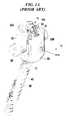
- FIG. 1Ais a perspective view of a prior art bone anchor assembly
- FIG. 1Bis an exploded view of the bone anchor assembly of FIG. 1A ;
- FIG. 1Cis a top view of the bone anchor assembly of FIG. 1A ;
- FIG. 1Dis a cross-sectional view of the bone anchor assembly of FIG. 1A ;
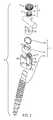
- FIG. 2is an exploded view of a bone anchor assembly including a multi-part bone anchor
- FIG. 3is a side view of a shank of the bone anchor of FIG. 2 ;
- FIG. 3Ais a side view of an alternate shank of the bone anchor of FIG. 2 ;
- FIG. 4is a perspective view of a ball of the bone anchor of FIG. 2 ;
- FIG. 5Ais a perspective view of a clip of the bone anchor of FIG. 2 ;
- FIG. 5Bis a perspective view of another embodiment of a clip
- FIG. 5Cis a perspective view of another embodiment of a clip
- FIG. 6Ais a side view of the multi-part bone anchor of FIG. 2 shown fully assembled
- FIG. 6Bis a perspective view of the clip of FIG. 5A engaged with the shank of FIG. 3 ;
- FIG. 6Cis a perspective view of the clip of FIG. 5A engaged with the ball of FIG. 4 ;
- FIG. 6Dis a cross-sectional view of the bone anchor of FIG. 6A ;
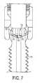
- FIG. 7is a cross-sectional view of another embodiment of a bone anchor.
- various bone anchor assemblies and methodshaving a multi-component bone anchor that is configured to allow the shank of the bone anchor to be bottom-loaded into a receiver member before or during a procedure.
- Such devices and methodscan allow for the use of bone anchors having large diameter shanks capable of withstanding greater bending forces, while still utilizing a relatively low-profile receiver member for coupling a spinal fixation element to the bone anchor.
- the bone anchor assemblies and methodscan also be particularly useful with favored-angle bone anchors in which a cone of angulation of the bone anchor relative to the receiver member is biased in one direction.
- FIGS. 1A-1Dillustrate a prior art bone anchor assembly 10 including a bone anchor 12 , a receiver member 14 for receiving a spinal fixation element, such as a spinal rod 22 , to be coupled to the bone anchor 12 , and a closure mechanism 16 to capture a spinal fixation element within the receiver member 14 and fix the spinal fixation element with respect to the receiver member 14 .
- the bone anchor 12includes a proximal head 18 and a distal shaft 20 configured to engage bone.
- the receiver member 14has a proximal end 26 having a pair of spaced apart arms 28 A, 28 B defining a recess 30 therebetween and a distal end 32 having a distal end surface 34 defining an opening through which at least a portion of the bone anchor 12 extends.
- the closure mechanism 16can be positionable between and can engage the arms 28 A, 28 B to capture a spinal fixation element, e.g., a spinal rod 22 , within the receiver member 14 and fix the spinal fixation element with respect to the receiver member 14
- the proximal head 18 of the bone anchor 12is generally in the shape of a truncated sphere having a planar proximal surface 36 and an approximately spherically-shaped distal surface 38 .
- the illustrated bone anchor assemblyis a polyaxial bone screw designed for posterior implantation in the pedicle or lateral mass of a vertebra.
- the proximal head 18 of the bone anchor 12engages the distal end 32 of the receiver member 14 in a ball and socket like arrangement in which the proximal head 18 the distal shaft 20 can pivot relative to the receiver member 14 , i.e., the distal end 32 defines a polyaxial seat on a proximal surface thereof for the bone anchor 12 .
- the distal surface 38 of the proximal head 18 of the bone anchor 12 and a mating surface within the distal end 32 of the receiver member 14can have any shape that facilitates this arrangement, including, for example, spherical (as illustrated), toroidal, conical, frustoconical, and any combinations of these shapes.
- the distal shaft 20 of the bone anchor 12can be configured to engage bone and, in the illustrated embodiment, includes an external bone engaging thread 40 .
- the thread form for the distal shaft 20including the number of threads, the pitch, the major and minor diameters, and the thread shape, can be selected to facilitate connection with bone. Exemplary thread forms are disclosed in U.S. Patent Application Publication No. 2011/0288599, filed on May 18, 2011, and in U.S. Provisional Patent Application Ser. No. 61/527,389, filed Aug. 25, 2011, both of which are incorporated herein by reference.
- the distal shaft 20can also include other structures for engaging bone, including a hook.
- the distal shaft 20 of the bone anchor 12can be cannulated, having a central passage or cannula extending the length of the bone anchor to facilitate delivery of the bone anchor over a guide wire in, for example, minimally-invasive procedures.
- Other components of the bone anchor assemblyincluding, for example, the closure member 16 , the receiver member 14 , and the compression member 60 (discussed below) can be cannulated or otherwise have an opening to permit delivery over a guide wire.
- the distal shaft 20can also include one or more sidewall openings or fenestrations that communicate with the cannula to permit bone in-growth or to permit the dispensing of bone cement or other materials through the bone anchor 12 .
- the sidewall openingscan extend radially from the cannula through the sidewall of the distal shaft 20 .
- Exemplary systems for delivering bone cement to the bone anchor assembly 10 and alternative bone anchor configurations for facilitating cement deliveryare described in U.S. Patent Application Publication No. 2010/0114174, filed on Oct. 29, 2009, which is hereby incorporated herein by reference.
- the distal shaft 20 of the bone anchor 12can also be coated with materials to permit bone growth, such as, for example, hydroxyapatite, and the bone anchor assembly 10 can be coated partially or entirely with anti-infective materials, such as, for example, tryclosan.
- the proximal end 26 of the receiver member 14includes a pair of spaced apart arms 28 A, 28 B defining a U-shaped recess 30 therebetween for receiving a spinal fixation element, e.g., a spinal rod 22 .
- Each of the arms 28 A, 28 Bcan extend from the distal end 32 of the receiver member 14 to a free end.
- the outer surfaces of each of the arms 28 A, 28 Bcan include a feature, such as a recess, dimple, notch, projection, or the like, to facilitate connection of the receiver member 14 to instruments.
- the outer surface of each arm 28 A, 28 Bcan include an arcuate groove at the respective free end of the arms. Such grooves are described in more detail in U.S. Pat. No. 7,179,261, issued on Feb. 20, 2007, which is hereby incorporated herein by reference.
- At least a portion of the proximal end surface 48 of the receiver member 12defines a plane Y.
- the receiver member 14has a central longitudinal axis L
- the distal end 32 of the receiver member 14includes a distal end surface 34 which is generally annular in shape defining a circular opening through which at least a portion of the bone anchor 12 extends.
- a distal end surface 34which is generally annular in shape defining a circular opening through which at least a portion of the bone anchor 12 extends.
- the distal shaft 20 of the bone anchor 12can extend through the opening.
- At least a portion of the distal end surface 34defines a plane X.
- the bone anchor 12can be selectively fixed relative to the receiver member 14 . Prior to fixation, the bone anchor 12 is movable relative to the receiver member 14 within a cone of angulation generally defined by the geometry of the distal end 32 of the receiver member and the proximal head 18 of the bone anchor 12 .
- the illustrated bone anchoris a favored-angle polyaxial screw in which the cone of angulation is biased in one direction. In this manner, the bone anchor 12 is movable relative to the receiver member 14 in at least a first direction, indicated by arrow A in FIG. 1D , at a first angle C relative to the central longitudinal axis L of the receiver member 14 .
- the bone anchor 12is also movable in at least a second direction, indicated by arrow B in FIG.
- the distal shaft 20 of the bone anchor 12defines a neutral axis 48 with respect to the receiver member 14 .
- the neutral axis 48can be perpendicular to the plane X defined by the distal end surface 34 and intersects the center point of the opening in the distal end surface 34 through which the distal shaft 20 of the bone anchor 12 extends.
- the neutral axis 48can be oriented at an angle to the central longitudinal axis L of the receiver member 14 .
- the proximal end 26 of the receiver member 14can include a proximal first bore 50 coaxial with a first central longitudinal axis N (which is coincident with longitudinal axis L) and a distal second bore 52 coaxial with a second central longitudinal axis M (which is coincident with the neutral axis 48 ) and the first central longitudinal axis N and second central longitudinal axis M can intersect one another.
- the angle between the plane X and the plane Y and the angle between the axis L and the axis Mcan be selected to provide the desired degree of biased angulation.
- Examples of favored angled polyaxial screwsare described in more detail in U.S. Pat. No. 6,974,460, issued on Dec. 13, 2005, and in U.S. Pat. No. 6,736,820, issued on May 18, 2004, both of which are hereby incorporated herein by reference.
- the bone anchor assemblycan be a conventional (non-biased) polyaxial screw in which the bone anchor pivots in the same amount in every direction and has a neutral axis that is coincident with the central longitudinal axis L of the receiver member.
- the spinal fixation elemente.g., the spinal rod 22
- the spinal fixation elementcan either directly contact the proximal head 18 of the bone anchor 12 or can contact an intermediate element, e.g., a compression member 60 .
- the compression member 60can be positioned within the receiver member 14 and interposed between the spinal rod 22 and the proximal head 18 of the bone anchor 12 to compress the distal outer surface 38 of the proximal head 18 into direct, fixed engagement with the distal inner surface of the receiver member 14 .
- the compression member 60can include a pair of spaced apart arms 62 A and 62 B defining a U-shaped seat 64 for receiving the spinal rod 22 and a distal surface 66 for engaging the proximal head 18 of the bone anchor 12 .
- the proximal end 26 of the receiver member 14can be configured to receive a closure mechanism 16 positionable between and engaging the arms 28 A, 28 B of the receiver member 14 .
- the closure mechanism 16can be configured to capture a spinal fixation element, e.g., a spinal rod 22 , within the receiver member 14 , to fix the spinal rod 22 relative to the receiver member 14 , and to fix the bone anchor 12 relative to the receiver member 14 .
- the closure mechanism 16can be a single set screw having an outer thread for engaging an inner thread 42 provided on the arms 28 A, 28 B of the receiver member 14 .
- the closure mechanism 16comprises an outer set screw 70 positionable between and engaging the arms 28 A, 28 B of the receiver member 14 and an inner set screw 72 positionable within the outer set screw 70 .
- the outer set screw 70is operable to act on the compression member 60 to fix the bone anchor 12 relative to the receiver member 14 .
- the inner set screw 72is operable to act on the spinal rod 22 to fix the spinal rod 22 relative to the receiver member 14 .
- the closure mechanism 16permits the bone anchor 12 to be fixed relative to the receiver member 14 independently of the spinal rod 22 being fixed to the receiver member 14 .
- the outer set screw 70can engage the proximal end surfaces of the arms 62 A, 62 B of the compression member 60 to force the distal surface 66 of the compression member 60 into contact with the proximal head 18 of bone anchor 12 , which in turn forces the distal surface 38 of the proximal head 18 into fixed engagement with the distal inner surface of the receiver member 14 .
- the inner set screw 72can engage the spinal rod 22 to force the spinal rod 22 into fixed engagement with the rod seat 64 of the compression member 60 .
- the outer set screw 70includes a first outer thread 74 for engaging a complementary inner thread 42 on the arms 28 A, 28 B of the receiver member 14 .
- the outer set screw 74includes a central passage 96 from a top surface 98 of the outer set screw 74 to a bottom surface 100 of the outer set screw 74 for receiving the inner set screw 72 .
- the central passage 96can includes an inner thread 102 for engaging a complementary outer thread 104 on the inner set screw 72 .
- the thread form for the inner thread 102 and the outer thread 104including the number of threads, the pitch, major and minor diameter, and thread shape, can be selected to facilitate connection between the components and transfer of the desired axial tightening force.
- the top surface 98 of the outer set screw 74can have one or more drive features to facilitate rotation and advancement of the outer set screw 74 relative to the receiver member 14 .
- the illustrated outer set screw 74includes drive features in the form of a plurality of cut-outs 106 spaced-apart about the perimeter of the top surface 98 .
- the inner set screw 104can include drive features for receiving an instrument to rotate and advance the inner set screw 72 relative to the outer set screw 74 .
- the illustrated inner set screw 104includes drive features in the form of a central passage 108 having a plurality of spaced apart, longitudinally oriented cut-outs for engaging complementary features on an instrument.
- the bone anchor assembly 10can be used with a spinal fixation element such as rigid spinal rod 22 .
- a spinal fixation elementsuch as rigid spinal rod 22 .
- the various components of the bone anchor assemblies disclosed herein, as well as the spinal rod 22can be constructed from various materials, including titanium, titanium alloys, stainless steel, cobalt chrome, PEEK, or other materials suitable for rigid fixation.
- the spinal fixation elementcan be a dynamic stabilization member that allows controlled mobility between the instrumented vertebrae.
- bonecan be prepared to receive the bone anchor assembly 10 , generally by drilling a hole in the bone which is sized appropriately to receive the bone anchor 12 .
- the bone anchor assembly 10can be assembled, which can include assembling the bone anchor 12 and the receiver member 14 , so that the distal shaft 20 extends through the opening in the distal end 32 of the receiver member 14 and the proximal head 18 of the bone anchor 12 is received in the distal end 32 of the receiver member 14 .
- a driver toolcan be fitted with the bone anchor 12 to drive the bone anchor 12 into the prepared hole in the bone.
- the compression member 60can be positioned within the receiver member 14 such that the arms 62 A, 62 B of the compression member are aligned with the arms 28 A, 28 B of the receiver member 14 and the lower surface of the compression member 14 is in contact with the proximal head 18 of the bone anchor 12 .
- a spinal fixation elemente.g., the spinal rod 22
- the closure mechanism 16can be engaged with the inner thread 42 provided on the arms 28 A, 28 B of the receiver member 14 .
- a torsional forcecan be applied to the outer set screw 70 to move it within the recess 30 using a tool which can engage the plurality of cut-outs 106 in the upper facing surface of the outer set screw 70 , so as to force the compression member 60 onto the proximal head 18 of the bone anchor 12 .
- Torsional forcescan then be applied to the inner set screw 72 to move it relative to the outer set screw 70 so that it contacts the spinal rod 22 and can, for example, fix the spinal rod 22 relative to the receiver member 14 and the bone anchor 12 .
- inventive bone anchor assembliesare described below. Except as indicated below, the structure, operation, and use of these embodiments is similar or identical to that of the bone anchor assembly 10 described above. Accordingly, a detailed description of said structure, operation, and use is omitted here for the sake of brevity.
- FIG. 2illustrates a bone anchor assembly 110 that is similar to the bone anchor assembly 10 shown in FIGS. 1A and 1B , except that the bone anchor assembly 110 includes a multi-component bone anchor.
- the bone anchorincludes a shank 120 configured to engage bone, a spherical head or ball 118 , and a clip 180 configured to be engaged between and to mate the ball 118 to the shank 120 in an assembled configuration.
- the shank 120can be proximally advanced, e.g., bottom-loaded, into the receiver member 14 and then mated to the ball 118 by the clip 180 .
- the ball 180can be polyaxially seated within a polyaxial seat in the receiver member 14 in a ball and socket like arrangement such that the ball 118 and the shank 120 can pivot relative to the receiver member 14 .
- the clip 180will lock the ball 118 to the shank 120 such that the shank 120 is mated to the receiver member 14 .
- the shank 120can be polyaxially moved relative to the receiver member 14 , and once in a desired position a closure mechanism can be applied to the receiver member to lock a spinal fixation element, such as a spinal rod, therein and to also lock the receiver member 14 in a fixed position relative to the shank 120 .
- the shank 120is illustrated in more detail in FIG. 3 , and as shown the elongate shank 120 includes a proximal head portion 120 p and a distal portion 120 d .
- the distal bone-engaging portion 120 dis in the form of a threaded shank having an external bone engaging thread 140
- the proximal portion 120 pis thread-free and is in the form of a head.
- the proximal portion 120 pcan have various shapes and sizes
- the proximal portion 120 pis generally cylindrical and has a major diameter D P that is less than a major diameter D D of the distal portion 120 d .
- the major diameter D P of the proximal head portion 120 p of the shank 120can be less than a diameter D R (not shown) of an opening or aperture 35 in a distal end 32 of the receiver member 14 such that the proximal head portion 120 p can be received through the aperture 35 .
- the distal portion 120 d of the shank 120can have a major diameter D D that is greater than the diameter D R (not shown) of the aperture 35 in the distal end 32 of the receiver member 14 such that the distal portion 120 d of the shank 120 is prevented from passing through the aperture 35 .
- proximal portion 120 p of the shank 120can be proximally advanced through the aperture 35 in the distal end 32 of the receiver member 14 , i.e., “bottom-loaded” into the receiver member 14 .
- the shank 120need not have a major diameter D D that is greater than the diameter of the aperture 35 in receiver member 14 , and any sized shank can be used with the present invention.
- the proximal portion 120 p of the shank 120can also have a substantially planar proximal surface 121 that can optionally include a tool receiving recess therein (see FIG. 6B ).
- proximal head portion 120 p of the shank 120is configured to mate with the clip 180 , which also mates to the ball 118 to thereby lock the ball 118 onto the proximal head portion 120 p of the shank 120 .
- a substantially cylindrical sidewall 125 of the proximal head portion 120 pcan include a first annular groove 127 formed therein to receive the clip 180 .
- the annular groove 127 and the clip 180can be configured to prevent axial translation of the clip 180 with respect to the shank 120 when mated together.
- the groovecan have a variety of configurations, but in an exemplary embodiment, the annular groove 127 is formed around the entire circumference of the shank 120 and has a constant depth X S and a constant height H S . In other embodiments, as discussed below, the groove can be formed around a partial circumference of shank and/or can have varying dimensions.
- the location of the annular groove 127can also vary, but it is preferably disposed at a location along the proximal head portion 120 p of the shank that is configured to retain the ball 118 in a position such as that shown in FIG. 6A .
- the annular groove 127is located at an intermediate position between proximal and distal ends of the proximal head portion 120 p.
- FIG. 7shows another embodiment of a shank 720 that includes a groove 727 that intersects a tool receiving recess or driving interface 723 .
- a clip 780 engaged in the groove 727can bear against an instrument, e.g., a driving tool, in the driving interface 723 such that the shank 720 is mated to and retained on the instrument.
- the groove 727can include a first portion 728 that intersects the driving interface 723 and that is configured to allow the clip 780 to bear against a tool within the driving interface.
- the first portion 728can be in the form of opposed cut-outs or openings extending through the sidewall 725 of the shank (compare with FIG.
- the groove 727can also include a second portion 729 that does not penetrate the sidewall 725 of the shank 720 and that is configured to retain the clip 780 outside of the driving interface 723 .
- the second portion 729can likewise be formed in opposed sidewalls of the shank 720 .
- the proximal head portion 120 p of the shankcan include various other features.
- the head portion 120 pcan be configured to facilitate mating with the clip 180 .
- the head portion 120 pcan include a tapered lead portion at a proximal end thereof that is configured to gradually expand the clip 180 as the clip 180 is advanced distally onto the shank 120 .
- the tapered lead portionis a substantially spherical surface 124 that extends between the proximal surface 121 and the cylindrical sidewall 125 on the proximal head portion 120 p .
- the tapered lead portioncan have various configurations and can be either formed on the proximal head portion 120 p , as shown in FIG. 3 , or can be separate therefrom.
- the tapered lead portioncan be a separate member or blank 124 a sized and shaped like the spherical surface 124 and configured to reversibly mate, via a reversible mating 124 b , to the proximal head portion 120 p of the shank 120 such that a clip 180 can be expanded when advanced distally on the blank 124 a and, when the blank 124 a is mated with the proximal portion 120 p of the shank 120 , the clip 180 can be further advanced directly onto the proximal portion 120 p of the shank and the blank 124 a can be removed from the shank 120 .
- the blank 124 acan be mated to the shank 120 using various techniques, such as threads, a twist-lock,
- the ball 118 of the bone anchoris shown in more detail in FIG. 4 , and is configured to receive the proximal head portion 120 p of the shank 120 therein with the clip 180 engaged there between. While the ball 118 can have various configurations, in an exemplary embodiment, the ball 118 is at least partially spherical to allow the ball 118 to be seated within a spherical recess in the receiver member 14 to form a ball and socket like arrangement that allows the shank 120 to pivot relative to the receiver member 14 . As shown in FIG. 4 , the ball 118 can be a truncated sphere with a substantially spherical exterior surface 190 .
- the spherical exterior surface 190can provide for a full range of polyaxial motion
- the spherical outer surface 190can include one or more flat portions (not shown) that correspond to flat portions of the receiver member 14 such that angulation of the bone anchor is limited to a single plane.
- the spherical surface 124 of the shank and the spherical exterior surface 190 of the ball 118can form a substantially continuous spherical surface (see FIG. 6A ).
- the spherical surface 124 of the shank 120 and the spherical exterior surface 190 of the ball 118can share a common center point and can form an interrupted spherical surface.
- the dimensions of the ballcan also vary, but in an exemplary embodiment, the ball 118 can have a diameter D O that is greater than the diameter D R (not shown) of the aperture 35 in the distal end 32 of the receiver member 14 such that the ball 118 is prevented from passing through the aperture 35 .
- the ball 118can have a height H O that is less than or equal to a height H P of the proximal head portion 120 p of the shank 120 .
- the ball 118is rigid and inflexible.
- the ball 118can be non-expandable so as to prevent the outer ring from deforming and detaching from the shank 120 when the bone anchor is coupled to the receiver member 14 .
- the ball 118can be solid with an unbroken circumference, having no slits or cuts formed therein such that it does not bend, compress, or expand.
- the ball 118can include an inner surface 193 that defines a lumen or bore 194 extending therethrough that is configured to receive the proximal portion 120 p of the shank 120 .
- the bore 194is cylindrical to correspond with the proximal head portion 120 p of the shank 120 (see FIG. 6D ), however, it will be understood that the bore can have various other shapes, such as hourglass or frustoconical, for example.
- the inner surface 193 of the bore 194 of the ball 118can include a second annular groove 117 formed therein for seating at least a portion of the clip 180 .
- the second annular groovecan have a variety of configurations, but in an exemplary embodiment, the annular groove 117 is formed around the entire circumference of the bore 194 and has a constant depth (not shown) and a constant height H B . In other embodiments, as discussed below, the groove 117 can be formed around a partial circumference of bore in the ball 118 and/or can have varying dimensions.
- the location of the annular groove 117can also vary, but it is preferably disposed at a location along the length of the bore that is configured to retain the ball 118 on the shank 120 in a position such as that shown in FIG. 6A .
- the annular groove 117is located at an intermediate position between proximal and distal ends of the bore 194 in the ball 118 .
- the clip 180is illustrated in more detail in FIG. 5A and can generally be circular or cylindrical.
- the clip 180can be configured to be partially seated within the first annular groove 127 of the shank 120 and partially seated within the second annular groove 117 of the ball 118 to mate the shank 120 with the ball 118 .
- the clip 180is C-shaped with a radial slit 181 for allowing a diameter D C of the clip to be adjusted.
- the clip 180can have a height H C that is less than or equal to a height H S of the first annular groove 127 and less than or equal to a height H B of the second annular groove 117 .
- the height H C of the clipis substantially equal to each of the height H S of the first annular groove 127 and the height H B of the second annular groove 117 such that, when the clip 180 is partially seated within the first and second annular grooves 127 , 117 to mate the shank 120 and the ball 118 , the ball 118 and the shank 120 are prevented from translating axially relative to one another.
- the clip 180can also have a width X C that is less than each of a depth X S of the first annular groove 127 and a depth X B of the second annular groove 117 , and that is equal to or less than a combined depth X S of the first annular groove 127 and depth X B of the second annular groove such that the clip 180 can be entirely recessed within both grooves.
- the clip 180has a width X C that is less than the combined depth X S of the first annular groove 127 and depth X B of the second annular groove 117 so as to allow the clip 180 to expand or contract into one of the grooves 117 , 127 as the shank and ball are advanced relative to one another. While FIG.
- FIG. 5Aillustrates a C-shaped clip
- the clipcan have various other configurations, such as an E-clip, a K-type clip, a wire, band, tube, or ring without a slit, as discussed further below, etc.
- the slit 181 in the clip 180can allow the clip to expand and contract such that a maximum diameter D C of the clip 180 is adjustable, i.e., can increase or decrease.
- the maximum diameter D Ccan increase when the proximal head portion 120 p of the shank 120 is being advanced through a lumen 186 of the clip 180 , or the diameter D C can decrease when the clip 180 is being advanced through the lumen 194 of the ball 118 .
- the slitcan have a variety of configurations.
- the slit 181can be in the form of a radial cut extending longitudinally through the clip 180 from an outer surface 187 to an inner surface 188 thereof.
- the slit 181defines straight opposed first and second sides 182 a , 182 b .
- the slitcan be non-linear, interlocking or non-interlocking.
- FIG. 5Bshows another embodiment of a clip 680 that has a non-linear slit 681 that defines a first side 682 a with a tab 683 formed thereon and a second side 682 b with a complementary recess 684 formed therein such that the tab 683 and the recess 684 are configured to interlock the first and second sides 682 a , 682 b .
- the slitcan vary in size and a distance between first and second sides 182 a , 182 b of the slit can increase or decrease as the ring 180 expands or contracts.
- the clipcan be slit-free while still being flexible to allow the diameter to increase and decrease.
- FIG. 5Cillustrates a clip 685 in the form of a continuous ring or band having an uninterrupted circumference, i.e., without a slit, that can expand and contract.
- the clipcan be formed from an expandable material such that a maximum diameter of the clip can increase and/or decrease when a force is applied thereto.
- Exemplary materialsinclude, by way of non-limiting example, shape memory alloys, such as nitinol, and any material that has elastic properties.
- the clipcan heated and/or cooled such that a maximum diameter of the clip can be adjusted.
- FIGS. 6A and 6Dshow an exemplary assembled bone anchor. While the method is shown in connection with the bone anchor assembly of FIG. 2 , the method can be used with any of the bone anchor assemblies disclosed herein.
- the proximal portion 120 p of the shank 120can be proximally advanced through the aperture 35 in the distal end 32 of the receiver member 14 , i.e., bottom-loaded into the receiver member 14 , and the ball 118 can be top-loaded into the receiver member 14 thereafter.
- the clip 180can initially be seated in one of the annular groove 127 in the shank 120 (as shown in FIG. 6B ) and the annular groove 117 in the ball (as shown in FIG. 6C ).
- the clip 180can be initially seated in the annular groove 127 in the shank 120 .
- the clip 180can have a width X C that is equal to a depth X S of the first annular groove 127 .
- the diameter D C of the clip 180can be expanded, e.g., increased, to receive the proximal head portion 120 p of the shank 120 within the lumen 186 thereof.
- the clip 180can be expanded over a tapered lead, e.g., a spherical surface 124 formed at a proximal end of the proximal head portion 120 p of the shaft 120 or, alternatively, the clip 180 can be expanded over a tapered blank, which can then be displaced by the proximal head portion 120 p of the shank 120 when the clip 180 is sufficiently expanded.
- a tapered leade.g., a spherical surface 124 formed at a proximal end of the proximal head portion 120 p of the shaft 120
- the clip 180can be expanded over a tapered blank, which can then be displaced by the proximal head portion 120 p of the shank 120 when the clip 180 is sufficiently expanded.
- the depth X S of the first annular groove 127can allow the clip to compress and be fully received within the annular groove 127 .
- the clip 180can once again return to its original state such that the clip 180 extends partially into each groove 117 , 127 .
- the clip 180can be initially seated in the annular groove 117 in the ball 118 .
- the clip 180can have a width X C that is equal to a depth X B of the second annular groove 117 .
- the diameter D C of the clip 180can be compressed, e.g., decreased, as the clip 180 is advanced through the lumen 194 of the ball 118 .
- the clipcan return to its original state to be seated within the annular groove 117 .
- the depth X B of the second annular groove 117can allow the clip to expand and be fully received within the annular groove 117 .
- the shank 120 and the ball 118will be locked a substantially fixed relationship relative to each other, as shown in FIG. 6D .
- the ball 118is sized to prevent passage through the aperture 35 of the receiver member 14 , the proximal portion 120 p of the shank 120 is maintained within the receiver member 14 .
- the multi-component bone anchorthus allows for assembly using a bottom loading technique. This can be particularly advantageous with large diameter shanks that are not sized to be distally advanced through the proximal end of the receiver and through the aperture in the receiver member.
- the secure mating connection between the componentsalso allows the ball 118 to be sized so as to prevent passage through the aperture 35 in the receiver member 14 , even when the shank 120 is fully angled to the maximum angulation allowed for the illustrated favored-angle bone anchor assembly.
- the bone anchor 120can be implanted in bone, either before or after coupling the receiver member 14 to the shank 120 , using a driver tool fitted with the bone anchor.
- the clip 180can intersect the driving interface 723 and can bear against the driver tool to retain shank on the driving tool.
- a compression memberif utilized, can be positioned within the receiver member 14 such that the arms 62 A, 62 B of the compression member 60 are aligned with the arms 28 A, 28 B of the receiver member 14 and the distal-facing surface of the compression member 60 is in contact with the bone anchor.
- the compression member 60can exert a frictional force on part of the bone anchor, e.g., the ball 118 , to maintain the shank 120 in a desired orientation relative to the receiver member 14 , while still allowing movement of the shank 120 with respect to the receiver member 14 .
- the receiver member 14can be pivoted or angulated relative to the bone anchor.
- One or more bone anchor assemblies(not shown) can also be deployed into bone using the same or different techniques.
- a spinal fixation elemente.g. the spinal rod 22
- the spinal rod 22can be positioned in the recess 30 of the receiver member 14 and can be manipulated in various ways using various tools so that the spinal rod 22 extends through one or more bone anchor assemblies. Manipulating the spinal rod 22 can change an angle of the receiver member 14 relative to the bone anchor.
- a closure mechanism 16can be engaged with the inner thread provided on the arms 28 A, 28 B of the receiver member 14 .
- the closure mechanism 16can fix the spinal rod 22 relative to the bone anchor assembly 110 , and also cause the compression member 60 to engage the part of the bone anchor, e.g., the ball 118 , to lock the receiver member 14 in a fixed position relative to the shank 120 .
Landscapes
- Health & Medical Sciences (AREA)
- Orthopedic Medicine & Surgery (AREA)
- Life Sciences & Earth Sciences (AREA)
- Surgery (AREA)
- Neurology (AREA)
- Heart & Thoracic Surgery (AREA)
- Engineering & Computer Science (AREA)
- Biomedical Technology (AREA)
- Nuclear Medicine, Radiotherapy & Molecular Imaging (AREA)
- Medical Informatics (AREA)
- Molecular Biology (AREA)
- Animal Behavior & Ethology (AREA)
- General Health & Medical Sciences (AREA)
- Public Health (AREA)
- Veterinary Medicine (AREA)
- Surgical Instruments (AREA)
Abstract
Description
Claims (15)
Priority Applications (2)
| Application Number | Priority Date | Filing Date | Title |
|---|---|---|---|
| US13/828,882US9775660B2 (en) | 2013-03-14 | 2013-03-14 | Bottom-loading bone anchor assemblies and methods |
| US15/692,822US10238441B2 (en) | 2013-03-14 | 2017-08-31 | Bottom-loading bone anchor assemblies and methods |
Applications Claiming Priority (1)
| Application Number | Priority Date | Filing Date | Title |
|---|---|---|---|
| US13/828,882US9775660B2 (en) | 2013-03-14 | 2013-03-14 | Bottom-loading bone anchor assemblies and methods |
Related Child Applications (1)
| Application Number | Title | Priority Date | Filing Date |
|---|---|---|---|
| US15/692,822ContinuationUS10238441B2 (en) | 2013-03-14 | 2017-08-31 | Bottom-loading bone anchor assemblies and methods |
Publications (2)
| Publication Number | Publication Date |
|---|---|
| US20140277158A1 US20140277158A1 (en) | 2014-09-18 |
| US9775660B2true US9775660B2 (en) | 2017-10-03 |
Family
ID=51531132
Family Applications (2)
| Application Number | Title | Priority Date | Filing Date |
|---|---|---|---|
| US13/828,882Active2033-05-18US9775660B2 (en) | 2013-03-14 | 2013-03-14 | Bottom-loading bone anchor assemblies and methods |
| US15/692,822ActiveUS10238441B2 (en) | 2013-03-14 | 2017-08-31 | Bottom-loading bone anchor assemblies and methods |
Family Applications After (1)
| Application Number | Title | Priority Date | Filing Date |
|---|---|---|---|
| US15/692,822ActiveUS10238441B2 (en) | 2013-03-14 | 2017-08-31 | Bottom-loading bone anchor assemblies and methods |
Country Status (1)
| Country | Link |
|---|---|
| US (2) | US9775660B2 (en) |
Cited By (23)
| Publication number | Priority date | Publication date | Assignee | Title |
|---|---|---|---|---|
| US10201377B2 (en) | 2008-02-04 | 2019-02-12 | Medos International Sarl | Methods for correction of spinal deformities |
| US10226282B2 (en) | 2012-09-28 | 2019-03-12 | Medos International Sarl | Bone anchor assemblies |
| US10238441B2 (en) | 2013-03-14 | 2019-03-26 | Medos International Sàrl | Bottom-loading bone anchor assemblies and methods |
| US20190150990A1 (en)* | 2014-10-21 | 2019-05-23 | Roger P. Jackson | Pivotal bone anchor receiver having an insert with post-placement tool deployment |
| US10321938B2 (en) | 2013-03-14 | 2019-06-18 | Medos International Sàrl | Locking compression members for use with bone anchor assemblies and methods |
| US10342582B2 (en) | 2013-03-14 | 2019-07-09 | DePuy Synthes Products, Inc. | Bone anchor assemblies and methods with improved locking |
| US10413342B2 (en) | 2013-03-14 | 2019-09-17 | Medos International Sárl | Bone anchor assemblies with multiple component bottom loading bone anchors |
| US20200146724A1 (en)* | 2018-11-08 | 2020-05-14 | Warsaw Orthopedic, Inc. | Spinal implant system and methods of use |
| US20210128201A1 (en)* | 2017-04-10 | 2021-05-06 | Life Spine, Inc. | Bottom loading polyaxial screw |
| US11234738B2 (en) | 2018-11-16 | 2022-02-01 | Roger P. Jackson | Pivotal bone anchor assembly having a deployable collet insert with internal pressure ring |
| US11439437B1 (en) | 2021-06-09 | 2022-09-13 | Medos International Sarl | Bottom loading bone anchor assemblies with drag retaining ring and related methods |
| US20220313332A1 (en)* | 2019-12-17 | 2022-10-06 | Roger P. Jackson | Bone anchor assembly with ring retainer and internal snap ring |
| US11751916B2 (en) | 2009-06-15 | 2023-09-12 | Roger P. Jackson | Pivotal bone anchor assembly with polyaxial screw having frusto-conical upper surface |
| US11911075B2 (en) | 2012-01-10 | 2024-02-27 | Roger P. Jackson | Pivotal bone anchor assembly with increased shank angulation |
| US11998247B2 (en) | 2009-06-15 | 2024-06-04 | Roger P. Jackson | Method of assembling a pivotal bone anchor assembly using insert tool deployment |
| US12053209B2 (en) | 2022-01-18 | 2024-08-06 | Roger P. Jackson | Spinal fixation systems with modular receiver and ring retainer sub-assemblies for connecting with universal shank heads |
| US12070249B2 (en) | 2014-06-04 | 2024-08-27 | Jackson Roger P | Pivotal bone anchor assembly with bottom loaded shank head engaging retainer and closure engaging insert |
| US12076055B2 (en) | 2013-01-28 | 2024-09-03 | Roger P. Jackson | Pivotal bone anchor assembly with favored-angle receiver having upper tool engagement grooves and break-off extensions |
| US12082853B2 (en) | 2014-10-21 | 2024-09-10 | Roger P. Jackson | Pivotal bone anchor assembly with positioner-retainer containment and insert tool deployment |
| US12127766B2 (en) | 2021-03-05 | 2024-10-29 | Medos International Sàrl | Selectively locking polyaxial screw |
| US12137945B2 (en) | 2018-09-13 | 2024-11-12 | Roger P. Jackson | Pivotal bone anchor system with modular receiver sub-assemblies and universal bone anchors |
| US12144523B2 (en) | 2017-04-10 | 2024-11-19 | Life Spine, Inc. | Head over head connector assembly |
| US12414801B2 (en) | 2022-11-03 | 2025-09-16 | Roger P. Jackson | Spinal fixation system with modular receiver sub-assemblies for connecting with bi-spherical universal shank heads |
Families Citing this family (7)
| Publication number | Priority date | Publication date | Assignee | Title |
|---|---|---|---|---|
| JP5865479B2 (en)* | 2011-03-24 | 2016-02-17 | ロジャー・ピー・ジャクソン | Multiaxial bone anchor with compound joint and pop-mounted shank |
| US20140277153A1 (en) | 2013-03-14 | 2014-09-18 | DePuy Synthes Products, LLC | Bone Anchor Assemblies and Methods With Improved Locking |
| US9833263B2 (en) | 2015-04-13 | 2017-12-05 | Medos International Sarl | Bone anchor assemblies with orientation indicator |
| US11026730B2 (en)* | 2017-05-10 | 2021-06-08 | Medos International Sarl | Bone anchors with drag features and related methods |
| US10610265B1 (en) | 2017-07-31 | 2020-04-07 | K2M, Inc. | Polyaxial bone screw with increased angulation |
| EP3949882B1 (en) | 2020-08-05 | 2023-10-11 | Biedermann Technologies GmbH & Co. KG | Bone anchoring device |
| US12364515B2 (en)* | 2021-03-05 | 2025-07-22 | Medos International Sàrl | Multi-feature polyaxial screw |
Citations (273)
| Publication number | Priority date | Publication date | Assignee | Title |
|---|---|---|---|---|
| US2788045A (en) | 1952-10-06 | 1957-04-09 | Rosan Joseph | Conventional truncated screw threads with small locking thread bonded therebetween |
| US2842180A (en) | 1950-02-23 | 1958-07-08 | Set Screw & Mfg Company | Self-locking threads with locking interference fit |
| US4124318A (en)* | 1978-03-23 | 1978-11-07 | General Motors Corporation | Splined assembly with retaining rings |
| EP0070660B1 (en) | 1981-07-17 | 1986-01-22 | American Motors (Canada) Inc. | Method of making cast iron engine blocks and the like |
| US4762024A (en)* | 1985-07-30 | 1988-08-09 | Dana Corporation | Shaft retaining means for a differential gear assembly |
| US5009017A (en)* | 1987-01-20 | 1991-04-23 | Caterpillar Inc. | Retaining pin having a positive keeper means |
| WO1991016020A1 (en) | 1990-04-26 | 1991-10-31 | Danninger Medical Technology, Inc. | Transpedicular screw system and method of use |
| US5129388A (en) | 1989-02-09 | 1992-07-14 | Vignaud Jean Louis | Device for supporting the spinal column |
| US5154719A (en) | 1990-02-19 | 1992-10-13 | Societe De Fabrication De Materiel Orthopedique - Sofamor | Implant for a device for osteosynthesis, in particular of the spine |
| US5306275A (en) | 1992-12-31 | 1994-04-26 | Bryan Donald W | Lumbar spine fixation apparatus and method |
| US5385565A (en) | 1992-09-21 | 1995-01-31 | Danek Medical, Inc. | Tool and method for derotating scoliotic spine |
| US5443467A (en) | 1993-03-10 | 1995-08-22 | Biedermann Motech Gmbh | Bone screw |
| US5486174A (en) | 1993-02-24 | 1996-01-23 | Soprane S.A. | Fastener for the osteosynthesis of the spinal column |
| US5487744A (en) | 1993-04-08 | 1996-01-30 | Advanced Spine Fixation Systems, Inc. | Closed connector for spinal fixation systems |
| US5501684A (en)* | 1992-06-25 | 1996-03-26 | Synthes (U.S.A.) | Osteosynthetic fixation device |
| US5520689A (en) | 1992-06-04 | 1996-05-28 | Synthes (U.S.A.) | Osteosynthetic fastening device |
| US5562661A (en) | 1995-03-16 | 1996-10-08 | Alphatec Manufacturing Incorporated | Top tightening bone fixation apparatus |
| US5580246A (en) | 1995-01-30 | 1996-12-03 | Fried; Paula S. | Dental implants and methods for extending service life |
| US5643260A (en) | 1995-02-14 | 1997-07-01 | Smith & Nephew, Inc. | Orthopedic fixation system |
| US5672176A (en) | 1995-03-15 | 1997-09-30 | Biedermann; Lutz | Anchoring member |
| US5782833A (en) | 1996-12-20 | 1998-07-21 | Haider; Thomas T. | Pedicle screw system for osteosynthesis |
| EP0857465A1 (en) | 1997-02-10 | 1998-08-12 | Patrice Francois Diebold | Separable screw for an osteosynthesis plate or for setting two bone fragments |
| US5797911A (en) | 1996-09-24 | 1998-08-25 | Sdgi Holdings, Inc. | Multi-axial bone screw assembly |
| US5879350A (en) | 1996-09-24 | 1999-03-09 | Sdgi Holdings, Inc. | Multi-axial bone screw assembly |
| US5885286A (en) | 1996-09-24 | 1999-03-23 | Sdgi Holdings, Inc. | Multi-axial bone screw assembly |
| DE29903342U1 (en) | 1999-02-24 | 1999-06-02 | Grzibek, Egbert, 97534 Waigolshausen | Fixing element for holding elements of spinal implants |
| US5941882A (en) | 1996-07-02 | 1999-08-24 | Societe Etudes Et Developpements S.E.D. | Medical screw particularly for surgery and emplacement tool |
| US5964591A (en) | 1997-04-09 | 1999-10-12 | Implant Innovations, Inc. | Implant delivery system |
| US5989250A (en) | 1996-10-24 | 1999-11-23 | Spinal Concepts, Inc. | Method and apparatus for spinal fixation |
| US6050997A (en) | 1999-01-25 | 2000-04-18 | Mullane; Thomas S. | Spinal fixation system |
| US6056753A (en) | 1998-07-13 | 2000-05-02 | Jackson; Roger P. | Set screw for use with osteosynthesis apparatus |
| US6068632A (en) | 1998-05-12 | 2000-05-30 | Carchidi; Joseph Edward | Bone tap apparatus |
| US6074391A (en) | 1997-06-16 | 2000-06-13 | Howmedica Gmbh | Receiving part for a retaining component of a vertebral column implant |
| US6077262A (en) | 1993-06-04 | 2000-06-20 | Synthes (U.S.A.) | Posterior spinal implant |
| US6090111A (en) | 1998-06-17 | 2000-07-18 | Surgical Dynamics, Inc. | Device for securing spinal rods |
| US6113601A (en) | 1998-06-12 | 2000-09-05 | Bones Consulting, Llc | Polyaxial pedicle screw having a loosely coupled locking cap |
| US6146383A (en) | 1998-02-02 | 2000-11-14 | Sulzer Orthopadie Ag | Pivotal securing system at a bone screw |
| US6224596B1 (en) | 1997-01-06 | 2001-05-01 | Roger P. Jackson | Set screw for use with osteosynthesis apparatus |
| US6224598B1 (en) | 2000-02-16 | 2001-05-01 | Roger P. Jackson | Bone screw threaded plug closure with central set screw |
| US6251112B1 (en) | 2000-04-18 | 2001-06-26 | Roger P. Jackson | Thin profile closure cap for open ended medical implant |
| US6258090B1 (en) | 2000-04-28 | 2001-07-10 | Roger P. Jackson | Closure for open ended medical implant and removal tool |
| US6261287B1 (en) | 1992-03-02 | 2001-07-17 | Stryker Trauma Gmbh | Apparatus for bracing vertebrae |
| US6280442B1 (en) | 1999-09-01 | 2001-08-28 | Sdgi Holdings, Inc. | Multi-axial bone screw assembly |
| US6296642B1 (en) | 1998-11-09 | 2001-10-02 | Sdgi Holdings, Inc. | Reverse angle thread for preventing splaying in medical devices |
| US6302888B1 (en) | 1999-03-19 | 2001-10-16 | Interpore Cross International | Locking dovetail and self-limiting set screw assembly for a spinal stabilization member |
| US6355038B1 (en) | 1998-09-25 | 2002-03-12 | Perumala Corporation | Multi-axis internal spinal fixation |
| US6379356B1 (en) | 2000-04-26 | 2002-04-30 | Roger P. Jackson | Closure for open ended medical implant |
| US6402757B1 (en) | 1999-03-12 | 2002-06-11 | Biomet, Inc. | Cannulated fastener system for repair of bone fracture |
| US6440132B1 (en) | 2000-05-24 | 2002-08-27 | Roger P. Jackson | Open head bone screw closure with threaded boss |
| US20020133159A1 (en) | 2000-12-08 | 2002-09-19 | Jackson Roger P. | Closure for open-headed medical implant |
| US6454772B1 (en) | 2000-12-08 | 2002-09-24 | Roger P. Jackson | Set screw for medical implant with gripping side slots |
| US6454768B1 (en) | 2000-12-05 | 2002-09-24 | Roger P. Jackson | Removable gripping set screw |
| US6458132B2 (en) | 2000-03-15 | 2002-10-01 | Gil-Woon Choi | Spine supporting system |
| US6475218B2 (en) | 2000-06-30 | 2002-11-05 | Sofamor, S.N.C. | Spinal implant for an osteosynthesis device |
| US6485491B1 (en) | 2000-09-15 | 2002-11-26 | Sdgi Holdings, Inc. | Posterior fixation system |
| US6488681B2 (en) | 2001-01-05 | 2002-12-03 | Stryker Spine S.A. | Pedicle screw assembly |
| US20030023243A1 (en) | 2001-07-27 | 2003-01-30 | Biedermann Motech Gmbh | Bone screw and fastening tool for same |
| US20030055426A1 (en) | 2001-09-14 | 2003-03-20 | John Carbone | Biased angulation bone fixation assembly |
| EP1295566A1 (en) | 1999-06-30 | 2003-03-26 | Surgival Co., S.A. | Polyaxial vertebral fixing system |
| US6540748B2 (en) | 1999-09-27 | 2003-04-01 | Blackstone Medical, Inc. | Surgical screw system and method of use |
| US20030073996A1 (en)* | 2001-10-17 | 2003-04-17 | Doubler Robert L. | Split ring bone screw for a spinal fixation system |
| US20030100896A1 (en) | 2001-11-27 | 2003-05-29 | Lutz Biedermann | Element with a shank and a holding element connected to it for connecting to a rod |
| US20030125741A1 (en) | 2001-12-28 | 2003-07-03 | Biedermann Motech Gmbh | Locking device for securing a rod-shaped element in a holding element connected to a shank |
| US20030153911A1 (en)* | 2002-02-13 | 2003-08-14 | Endius Incorporated | Apparatus for connecting a longitudinal member to a bone portion |
| US6629977B1 (en) | 1999-11-15 | 2003-10-07 | Arthrex, Inc. | Tapered bioabsorbable interference screw and method for endosteal fixation of ligaments |
| US6663656B2 (en) | 2001-02-26 | 2003-12-16 | Arthrex, Inc. | Torque driver for interference screw |
| US20040049190A1 (en) | 2002-08-09 | 2004-03-11 | Biedermann Motech Gmbh | Dynamic stabilization device for bones, in particular for vertebrae |
| US6726480B1 (en) | 1997-05-24 | 2004-04-27 | Straumann Holding Ag | Support for sustaining and/or forming a dental prosthesis |
| US6726687B2 (en) | 2000-12-08 | 2004-04-27 | Jackson Roger P | Closure plug for open-headed medical implant |
| US6730089B2 (en) | 2002-08-26 | 2004-05-04 | Roger P. Jackson | Nested closure plug and set screw with break-off heads |
| US6736820B2 (en) | 2000-11-10 | 2004-05-18 | Biedermann Motech Gmbh | Bone screw |
| US6740086B2 (en) | 2002-04-18 | 2004-05-25 | Spinal Innovations, Llc | Screw and rod fixation assembly and device |
| US6755836B1 (en) | 2002-12-20 | 2004-06-29 | High Plains Technology Group, Llc | Bone screw fastener and apparatus for inserting and removing same |
| WO2004058081A1 (en) | 2002-12-20 | 2004-07-15 | High Plains Technology Group, Llc | Bone screw fastener and apparatus for inserting and removing same |
| US20040162560A1 (en) | 2003-02-19 | 2004-08-19 | Raynor Donald E. | Implant device including threaded locking mechanism |
| US20040186473A1 (en) | 2003-03-21 | 2004-09-23 | Cournoyer John R. | Spinal fixation devices of improved strength and rigidity |
| US6835196B2 (en) | 2001-03-27 | 2004-12-28 | Biedermann Motech Gmbh | Anchoring element |
| US6843790B2 (en) | 2001-03-27 | 2005-01-18 | Bret A. Ferree | Anatomic posterior lumbar plate |
| US20050055026A1 (en)* | 2002-10-02 | 2005-03-10 | Biedermann Motech Gmbh | Bone anchoring element |
| US6869433B2 (en) | 2001-01-12 | 2005-03-22 | Depuy Acromed, Inc. | Polyaxial screw with improved locking |
| US20050080415A1 (en) | 2003-10-14 | 2005-04-14 | Keyer Thomas R. | Polyaxial bone anchor and method of spinal fixation |
| US6884244B1 (en) | 2000-06-06 | 2005-04-26 | Roger P. Jackson | Removable medical implant closure for open headed implants |
| US20050153077A1 (en) | 2003-12-03 | 2005-07-14 | Anthony Gedeon | Method of resisting contaminant build up and oxidation of vehicle surfaces and other surfaces |
| US20050154391A1 (en) | 2003-12-30 | 2005-07-14 | Thomas Doherty | Bone anchor assemblies |
| US20050154393A1 (en) | 2003-12-30 | 2005-07-14 | Thomas Doherty | Bone anchor assemblies and methods of manufacturing bone anchor assemblies |
| US20050182401A1 (en)* | 2003-05-02 | 2005-08-18 | Timm Jens P. | Systems and methods for spine stabilization including a dynamic junction |
| US20050187548A1 (en) | 2004-01-13 | 2005-08-25 | Butler Michael S. | Pedicle screw constructs for spine fixation systems |
| EP1570794A1 (en) | 2004-03-04 | 2005-09-07 | U & I Corporation | Bone fixation apparatus, method and tool for assembling the same |
| US20050216003A1 (en) | 2004-03-03 | 2005-09-29 | Biedermann Motech Gmbh | Bone anchoring element for anchoring in a bone or vertebra, and stabilization device with such a bone anchoring element |
| US20050228326A1 (en) | 2004-03-31 | 2005-10-13 | Depuy Spine, Inc. | Head-to-head connector spinal fixation system |
| US20050273101A1 (en) | 2004-05-28 | 2005-12-08 | Aesculap Ag & Co. Kg | Bone screw and osteosynthesis device |
| US20050277928A1 (en) | 2004-06-14 | 2005-12-15 | Boschert Paul F | Spinal implant fixation assembly |
| US6981973B2 (en) | 2003-08-11 | 2006-01-03 | Mckinley Laurence M | Low profile vertebral alignment and fixation assembly |
| US20060025771A1 (en)* | 2000-08-23 | 2006-02-02 | Jackson Roger P | Helical reverse angle guide and advancement structure with break-off extensions |
| US6997927B2 (en) | 2000-12-08 | 2006-02-14 | Jackson Roger P | closure for rod receiving orthopedic implant having a pair of spaced apertures for removal |
| US7018378B2 (en) | 2000-12-27 | 2006-03-28 | Biedermann Motech Gmbh | Screw |
| US7022122B2 (en) | 1997-01-22 | 2006-04-04 | Synthes (U.S.A.) | Device for connecting a longitudinal bar to a pedicle screw |
| US20060083603A1 (en) | 2000-08-23 | 2006-04-20 | Jackson Roger P | Reverse angled threadform with anti-splay clearance |
| US20060100621A1 (en)* | 2004-11-10 | 2006-05-11 | Jackson Roger P | Polyaxial bone screw with discontinuous helically wound capture connection |
| US20060100622A1 (en)* | 2004-11-10 | 2006-05-11 | Jackson Roger P | Polyaxial bone screw with helically wound capture connection |
| US20060149241A1 (en) | 2002-04-18 | 2006-07-06 | Marc Richelsoph | Screw and rod fixation assembly and device |
| US20060161153A1 (en) | 2004-10-25 | 2006-07-20 | Alphaspine, Inc. | Pedicle screw systems and methods of assembling/installing the same |
| US7083621B2 (en) | 2003-04-25 | 2006-08-01 | Sdgi Holdings, Inc. | Articulating spinal fixation rod and system |
| US7087057B2 (en) | 2003-06-27 | 2006-08-08 | Depuy Acromed, Inc. | Polyaxial bone screw |
| EP1694229A1 (en) | 2003-12-17 | 2006-08-30 | SDGI Holdings, Inc. | Device for osteosynthesis of the spine |
| US20060200128A1 (en) | 2003-04-04 | 2006-09-07 | Richard Mueller | Bone anchor |
| US20060264933A1 (en) | 2005-05-04 | 2006-11-23 | Baker Daniel R | Multistage spinal fixation locking mechanism |
| US7179261B2 (en) | 2003-12-16 | 2007-02-20 | Depuy Spine, Inc. | Percutaneous access devices and bone anchor assemblies |
| US7186255B2 (en) | 2004-08-12 | 2007-03-06 | Atlas Spine, Inc. | Polyaxial screw |
| US20070055244A1 (en) | 2004-02-27 | 2007-03-08 | Jackson Roger P | Dynamic fixation assemblies with inner core and outer coil-like member |
| US7198625B1 (en)* | 2003-10-01 | 2007-04-03 | Stryker Corporation | Surgical instrument with retractable sheath |
| EP1774919A1 (en) | 2005-10-12 | 2007-04-18 | BIEDERMANN MOTECH GmbH | Poly-axial screw pivotable in a single plane |
| US20070118117A1 (en)* | 2005-10-20 | 2007-05-24 | Ebi, L.P. | Bone fixation assembly |
| US20070118123A1 (en) | 2005-11-21 | 2007-05-24 | Strausbaugh William L | Polyaxial bone anchors with increased angulation |
| US7223268B2 (en) | 2001-11-27 | 2007-05-29 | Biedermann Mötech GmbH | Locking device for securing a rod-shaped element in a holding element connected to a shank |
| US20070123870A1 (en) | 2005-07-18 | 2007-05-31 | Jeon Dong M | Bi-polar screw assembly |
| US20070123862A1 (en) | 2004-10-25 | 2007-05-31 | Warnick David R | Bone fixation system and method for using the same |
| EP1795134A1 (en) | 2005-11-17 | 2007-06-13 | BIEDERMANN MOTECH GmbH | Polyaxial screw for flexible rod |
| US7235075B1 (en) | 2002-05-21 | 2007-06-26 | Peter Metz-Stavenhagen | Anchoring element for securing a rod on a vertebra |
| US7261716B2 (en) | 1999-12-23 | 2007-08-28 | Karl Storz Gmbh & Co. Kg | Biodegradable interference screw and tool for attaching a transplant to a bone |
| US7264621B2 (en) | 2004-06-17 | 2007-09-04 | Sdgi Holdings, Inc. | Multi-axial bone attachment assembly |
| US20070265621A1 (en) | 2006-04-06 | 2007-11-15 | Wilfried Matthis | Bone anchoring device |
| US20070270813A1 (en) | 2006-04-12 | 2007-11-22 | Laszlo Garamszegi | Pedicle screw assembly |
| US20070293862A1 (en) | 2005-09-30 | 2007-12-20 | Jackson Roger P | Dynamic stabilization connecting member with elastic core and outer sleeve |
| US7322981B2 (en) | 2003-08-28 | 2008-01-29 | Jackson Roger P | Polyaxial bone screw with split retainer ring |
| US7325470B2 (en) | 2005-06-16 | 2008-02-05 | Orthohelix Surgical Designs, Inc. | Self-centering screw and retaining screw driver for use in surgery |
| US20080045953A1 (en) | 2006-07-14 | 2008-02-21 | Laszlo Garamszegi | Pedicle screw assembly with inclined surface seat |
| WO2008024937A2 (en) | 2006-08-23 | 2008-02-28 | Pioneer Surgical Technology, Inc. | Minimally invasive surgical system |
| US20080119852A1 (en) | 2006-11-20 | 2008-05-22 | Dalton Brian E | Bone repair device and method |
| US20080132957A1 (en)* | 2006-11-22 | 2008-06-05 | Wilfried Matthis | Bone anchoring device |
| US20080147129A1 (en) | 2006-11-17 | 2008-06-19 | Lutz Biedermann | Bone anchoring device |
| US20080161859A1 (en) | 2006-10-16 | 2008-07-03 | Innovative Delta Technology Llc | Bone Screw and Associated Assembly and Methods of Use Thereof |
| US20080200956A1 (en) | 2007-02-19 | 2008-08-21 | Tutela Medicus, Llc | Low Profile Orthopedic Fastener Assembly Having Enhanced Flexibility |
| US20080215100A1 (en) | 2006-12-22 | 2008-09-04 | Wilfried Matthis | Bone anchoring device |
| WO2008119006A1 (en) | 2007-03-27 | 2008-10-02 | Alpinespine Llc | Pedicle screw system configured to receive a straight or a curved rod |
| US20080269809A1 (en) | 2007-03-26 | 2008-10-30 | Laszlo Garamszegi | Bottom-loading pedicle screw assembly |
| US20080269805A1 (en) | 2007-04-25 | 2008-10-30 | Warsaw Orthopedic, Inc. | Methods for correcting spinal deformities |
| US7445627B2 (en) | 2005-01-31 | 2008-11-04 | Alpinespine, Llc | Polyaxial pedicle screw assembly |
| US20080288001A1 (en) | 2007-05-18 | 2008-11-20 | Trace Cawley | Cervical plate locking mechanism and associated surgical method |
| US20080294202A1 (en) | 2005-04-25 | 2008-11-27 | Joseph Peterson | Bone Anchor With Locking Cap and Method of Spinal Fixation |
| US20080312692A1 (en)* | 2007-06-15 | 2008-12-18 | Terrence Brennan | Multi-level spinal stabilization system |
| US20090005813A1 (en) | 2007-06-28 | 2009-01-01 | Angela Crall | Apparatus and methods for spinal implants |
| US20090012567A1 (en) | 2006-03-31 | 2009-01-08 | Lutz Biedermann | Locking assembly for securing a rod member in a receiver part for use in spinal or trauma surgery, bone anchoring device with such a locking assembly and tool therefor |
| US20090118772A1 (en) | 2007-06-01 | 2009-05-07 | Jennifer Diederich | Polyaxial bone anchor with increased angulation |
| WO2009073655A1 (en) | 2007-12-04 | 2009-06-11 | Cormed Nv/Sa | Spinal fixation assembly |
| EP2070485A1 (en) | 2007-12-13 | 2009-06-17 | Biedermann Motech GmbH | Anchoring device for anchoring a rod in bones or vertebrae |
| US20090163962A1 (en) | 2007-12-20 | 2009-06-25 | Aesculap Implant Systems, Inc. | Locking device introducer instrument |
| US7559943B2 (en) | 2004-06-09 | 2009-07-14 | Zimmer Spine, Inc. | Spinal fixation device with internal drive structure |
| US20090182384A1 (en) | 2008-01-14 | 2009-07-16 | Warsaw Orthopedic, Inc. | Material combinations for medical device implants |
| US20090198280A1 (en) | 2007-10-24 | 2009-08-06 | Frank Spratt | Assembly for Orthopaedic Surgery |
| US20090216280A1 (en) | 2008-02-04 | 2009-08-27 | John Hutchinson | Methods for Correction of Spinal Deformities |
| US20090228051A1 (en) | 2008-03-10 | 2009-09-10 | Eric Kolb | Bilateral vertebral body derotation system |
| US20090228053A1 (en) | 2008-03-10 | 2009-09-10 | Eric Kolb | Derotation instrument with reduction functionality |
| US20090254125A1 (en) | 2008-04-03 | 2009-10-08 | Daniel Predick | Top Loading Polyaxial Spine Screw Assembly With One Step Lockup |
| US20090264933A1 (en) | 2008-04-22 | 2009-10-22 | Warsaw Orthopedic, Inc. | Anchors for securing a rod to a vertebral member |
| US7615068B2 (en) | 2003-05-02 | 2009-11-10 | Applied Spine Technologies, Inc. | Mounting mechanisms for pedicle screws and related assemblies |
| US7625394B2 (en) | 2005-08-05 | 2009-12-01 | Warsaw Orthopedic, Inc. | Coupling assemblies for spinal implants |
| EP2129310A1 (en) | 2007-03-07 | 2009-12-09 | Roger P. Jackson | Poly axial bone screw with spherical capture, compression insert and alignment and retention structures |
| US20090326587A1 (en)* | 2005-07-08 | 2009-12-31 | Biedermann Motech Gmbh | Bone anchoring device |
| US20100004693A1 (en) | 2008-07-01 | 2010-01-07 | Peter Thomas Miller | Cam locking spine stabilization system and method |
| US20100010547A1 (en) | 2001-12-12 | 2010-01-14 | Ldr Medical | Implant for Osseous Anchoring with Polyaxial Head |
| US20100020272A1 (en) | 2006-09-08 | 2010-01-28 | Tae-Su Kim | Mirror effect liquid crystal display device using reflection polarizer |
| US20100023061A1 (en) | 2008-07-24 | 2010-01-28 | Randol David S | Locking mechanism with two-piece washer |
| US20100030272A1 (en)* | 2007-06-05 | 2010-02-04 | Spartek Medical Inc. | Spinal prosthesis having a three bar linkage for motion preservation and dynamic stabilization of the spine |
| US7670362B2 (en) | 2003-06-13 | 2010-03-02 | Tyco Healthcare Group Lp | Multiple member interconnect for surgical instrument and absorbable screw fastener |
| US7674277B2 (en) | 2004-12-01 | 2010-03-09 | Warsaw Orthopedic, Inc. | Side-loading bone anchor |
| US7678139B2 (en) | 2004-04-20 | 2010-03-16 | Allez Spine, Llc | Pedicle screw assembly |
| US7686833B1 (en) | 2004-04-02 | 2010-03-30 | Muhanna Nabil L | Ball jointed pedicle screw and rod system |
| US7699876B2 (en) | 2006-11-08 | 2010-04-20 | Ebi, Llc | Multi-axial bone fixation apparatus |
| US20100103099A1 (en) | 2007-05-26 | 2010-04-29 | Moon Key Lee | Pointing device using camera and outputting mark |
| US20100114174A1 (en) | 2008-10-30 | 2010-05-06 | Bryan Jones | Systems and Methods for Delivering Bone Cement to a Bone Anchor |
| WO2010056846A2 (en) | 2008-11-14 | 2010-05-20 | Ortho Innovations, Llc | Locking polyaxial ball and socket fastener |
| US7731736B2 (en) | 2004-06-14 | 2010-06-08 | Zimmer Spine, Inc. | Fastening system for spinal stabilization system |
| US7736380B2 (en) | 2004-12-21 | 2010-06-15 | Rhausler, Inc. | Cervical plate system |
| US20100152785A1 (en)* | 2008-12-16 | 2010-06-17 | Abbott Spine Inc. | Coaxially lockable poly-axial bone fastener assemblies |
| US20100160977A1 (en) | 2008-10-14 | 2010-06-24 | Gephart Matthew P | Low Profile Dual Locking Fixation System and Offset Anchor Member |
| US20100168747A1 (en)* | 2008-12-30 | 2010-07-01 | Howmedica Osteonics Corp. | Method and apparatus for removal of tissue |
| US7766946B2 (en) | 2005-07-27 | 2010-08-03 | Frank Emile Bailly | Device for securing spinal rods |
| US20100198272A1 (en) | 2007-07-20 | 2010-08-05 | Thomas Keyer | Polyaxial bone fixation element |
| US20100204735A1 (en) | 2009-02-11 | 2010-08-12 | Gephart Matthew P | Wide Angulation Coupling Members For Bone Fixation System |
| US20100222827A1 (en) | 2009-02-10 | 2010-09-02 | Bryan Griffiths | Screw with variable diameter cannulation and driver |
| US7789900B2 (en) | 2007-12-04 | 2010-09-07 | Expanding Orthopedics, Inc. | Double collet connector assembly for bone anchoring element |
| US20100234891A1 (en) | 2007-08-31 | 2010-09-16 | University Of South Florida | Translational manipulation polyaxial screw head |
| US20100305621A1 (en) | 2009-06-02 | 2010-12-02 | Alphatec Spine, Inc. | Bone screw assembly for limited angulation |
| US7846190B2 (en) | 2003-12-12 | 2010-12-07 | Integra Lifesciences Corporation | Apparatuses, systems and methods for bone fixation |
| US7850718B2 (en) | 2003-05-28 | 2010-12-14 | Spinevision | Connecting device for spinal osteosynthesis |
| US7867257B2 (en) | 2006-03-20 | 2011-01-11 | Synthes Usa, Llc | Poly-axial bone screw mating seat |
| EP2286748A1 (en) | 2009-08-20 | 2011-02-23 | BIEDERMANN MOTECH GmbH | Bone anchoring device, tool and method for assembling the same and tool for use with the same |
| US7901413B1 (en) | 2006-07-21 | 2011-03-08 | High Plains Technology Group, Llc | Surgical locking screw and driver arrangement |
| US7922748B2 (en) | 2006-06-16 | 2011-04-12 | Zimmer Spine, Inc. | Removable polyaxial housing for a pedicle screw |
| US20110106179A1 (en) | 2009-10-30 | 2011-05-05 | Warsaw Orthopedic, Inc. | Set Screw Having Variable Pitch Thread for Use With Spinal Implant Systems |
| WO2011059732A1 (en) | 2009-10-28 | 2011-05-19 | Bonovo Orthopedics, Inc. | Pedicle screws and methods of use |
| US7951175B2 (en) | 2005-03-04 | 2011-05-31 | Depuy Spine, Inc. | Instruments and methods for manipulating a vertebra |
| US7951173B2 (en) | 2007-05-16 | 2011-05-31 | Ortho Innovations, Llc | Pedicle screw implant system |
| US20110160779A1 (en) | 2008-09-05 | 2011-06-30 | Synthes Usa, Llc | Bone fixation assembly |
| US20110160778A1 (en) | 2009-11-16 | 2011-06-30 | Nexxt Spine, LLC | Poly-Axial Implant Fixation System |
| US20110190822A1 (en) | 2004-11-16 | 2011-08-04 | James Spitler | Internal Structure Stabilization System for Spanning Three or More Structures |
| US20110213424A1 (en) | 2009-08-12 | 2011-09-01 | Lutz Biedermann | receiving part for receiving a rod for coupling the rod to a bone anchoring element |
| WO2011109009A1 (en) | 2010-03-01 | 2011-09-09 | K2M, Inc. | Bone screw assembly with non-uniform material |
| US8016862B2 (en) | 2006-09-27 | 2011-09-13 | Innovasis, Inc. | Spinal stabilizing system |
| US20110245876A1 (en) | 2010-04-05 | 2011-10-06 | Brumfield David L | Fully-Adjustable bone fixation device |
| US20110245877A1 (en) | 2008-04-15 | 2011-10-06 | Madhavan Pisharodi | Rod and plate system for incremental reduction of the spine |
| WO2011127065A1 (en) | 2010-04-06 | 2011-10-13 | Seaspine, Inc. | System and methods for correcting spinal deformities |
| US20110251650A1 (en) | 2010-03-29 | 2011-10-13 | Lutz Biedermann | Bone anchoring device |
| US20110270322A1 (en) | 2010-05-03 | 2011-11-03 | Olsen Russell G | Surgical fastener and associated systems and methods |
| US8052724B2 (en) | 2003-06-18 | 2011-11-08 | Jackson Roger P | Upload shank swivel head bone screw spinal implant |
| US20110276098A1 (en) | 2010-05-05 | 2011-11-10 | Lutz Biedermann | Receiving part for receiving a rod for coupling the rod to a bone anchoring element, bone anchoring device, method and tool for assembling the same |
| US8057518B2 (en) | 2007-08-31 | 2011-11-15 | Depuy Spine, Inc. | Spanning connector for connecting a spinal fixation element and an offset bone anchor |
| US20110282399A1 (en) | 2007-01-22 | 2011-11-17 | Jackson Roger P | Polyaxial bone screw with cam connection and lock and release insert |
| US20110288599A1 (en) | 2010-05-19 | 2011-11-24 | Michael Michielli | Bone Anchors |
| US20110288592A1 (en) | 2010-03-30 | 2011-11-24 | Aeolin Llc | Side Opening Bone Fastener System |
| US8066744B2 (en) | 2006-11-10 | 2011-11-29 | Warsaw Orthopedic, Inc. | Keyed crown orientation for multi-axial screws |
| US8066745B2 (en) | 2005-07-29 | 2011-11-29 | X-Spine Systems, Inc. | Capless multiaxial screw and spinal fixation assembly and method |
| US8075599B2 (en) | 2005-10-18 | 2011-12-13 | Warsaw Orthopedic, Inc. | Adjustable bone anchor assembly |
| US8083774B2 (en) | 2000-06-23 | 2011-12-27 | Warsaw Orthopedic, Inc. | Percutaneous vertebral fusion system |
| US20120010661A1 (en) | 2003-08-20 | 2012-01-12 | Warsaw Orthopedic, Inc. | Multi-axial orthopedic device and system |
| US8097023B2 (en) | 2003-11-24 | 2012-01-17 | Warsaw Orthopedic, Inc. | Grommet assembly |
| US20120022593A1 (en) | 2010-07-22 | 2012-01-26 | Aesculap Implant Systems, Llc | Semi-dynamic fixation plate system |
| US20120035670A1 (en) | 2009-06-15 | 2012-02-09 | Jackson Roger P | Polyaxial bone anchors with pop-on shank, fully constrained friction fit retainer and lock and release insert |
| US20120046701A1 (en) | 2009-03-12 | 2012-02-23 | Euros | Spinal implant with a lockable ball joint |
| WO2012024665A2 (en) | 2010-08-20 | 2012-02-23 | K2M, Inc. | Spinal fixation system |
| US20120059425A1 (en) | 2010-03-08 | 2012-03-08 | Markku Biedermann | Locking Element for a Polyaxial Bone Anchor, Bone Plate Assembly and Tool |
| WO2012030712A1 (en) | 2010-08-30 | 2012-03-08 | Zimmer Spine, Inc. | Polyaxial pedicle screw |
| US20120059426A1 (en) | 2008-08-01 | 2012-03-08 | Jackson Roger P | Polyaxial bone anchors with pop-on shank, friction fit fully restrained retainer, insert and tool receiving features |
| WO2012035479A2 (en) | 2010-09-13 | 2012-03-22 | Facetmed Ltd. | Spinal fixation system and pedicle screw therefor |
| US20120078307A1 (en) | 2010-09-28 | 2012-03-29 | Raj Nihalani | Pedicle screws and dynamic adaptors |
| US20120083845A1 (en)* | 2010-10-05 | 2012-04-05 | Spartek Medical, Inc. | Compound spinal rod and method for dynamic stabilization of the spine |
| US8162989B2 (en) | 2002-11-04 | 2012-04-24 | Altus Partners, Llc | Orthopedic rod system |
| US8167912B2 (en) | 2007-02-27 | 2012-05-01 | The Center for Orthopedic Research and Education, Inc | Modular pedicle screw system |
| WO2012060868A1 (en) | 2010-11-02 | 2012-05-10 | Jackson Roger P | Polyaxial bone anchor with pop-on shank and pivotable retainer |
| EP2455028A1 (en) | 2010-11-22 | 2012-05-23 | Biedermann Technologies GmbH & Co. KG | Polyaxial bone anchoring device |
| US20120136395A1 (en) | 2010-11-24 | 2012-05-31 | Lutz Biedermann | Polyaxial bone anchoring device with enlarged pivot angle |
| US20120143266A1 (en) | 2009-06-15 | 2012-06-07 | Jackson Roger P | Polyaxial bone anchor with open planar retainer, pop-on shank and friction fit insert |
| US8197517B1 (en) | 2007-05-08 | 2012-06-12 | Theken Spine, Llc | Frictional polyaxial screw assembly |
| US8197518B2 (en) | 2007-05-16 | 2012-06-12 | Ortho Innovations, Llc | Thread-thru polyaxial pedicle screw system |
| US20120150239A1 (en) | 2010-10-15 | 2012-06-14 | Laszlo Garamszegi | Fixation screw assembly |
| US20120165882A1 (en) | 2010-12-27 | 2012-06-28 | Lutz Biedermann | Polyaxial bone anchoring device |
| US20120179209A1 (en) | 2010-12-10 | 2012-07-12 | Lutz Biedermann | Receiving part for receiving a rod for coupling the rod to a bone anchoring element and a bone anchoring device |
| US8221471B2 (en) | 2007-05-24 | 2012-07-17 | Aesculap Implant Systems, Llc | Pedicle screw fixation system |
| US20120185003A1 (en) | 2010-12-13 | 2012-07-19 | Lutz Biedermann | Bone anchoring device |
| US20120197313A1 (en) | 2011-01-28 | 2012-08-02 | Warsaw Orthopedic, Inc. | Angled Receiver Wall for Provisionally Fixing a Crown in a Multi-Axial Screw Assembly |
| US8236035B1 (en) | 2009-06-16 | 2012-08-07 | Bedor Bernard M | Spinal fixation system and method |
| US8241341B2 (en) | 2009-03-20 | 2012-08-14 | Spinal Usa, Inc. | Pedicle screws and methods of using the same |
| US20120209336A1 (en) | 2009-06-15 | 2012-08-16 | Jackson Roger P | Polyaxial bone anchor with pop-on shank, friction fit retainer and winged insert |
| US8257396B2 (en) | 2003-06-18 | 2012-09-04 | Jackson Roger P | Polyaxial bone screw with shank-retainer inset capture |
| US8267968B2 (en) | 2009-06-24 | 2012-09-18 | Neuropro Technologies, Inc. | Percutaneous system for dynamic spinal stabilization |
| US20120253404A1 (en) | 2003-05-02 | 2012-10-04 | Rachiotek, Llc | Method for stabilizing a spinal segment |
| US8287576B2 (en) | 2007-10-23 | 2012-10-16 | K2M, Inc. | Mono-axial, taper lock bone screw |
| US8298270B2 (en) | 2006-01-27 | 2012-10-30 | Warsaw Orthopedic, Inc. | Pivoting joints for spinal implants including designed resistance to motion and methods of use |
| US20120277805A1 (en) | 2011-04-29 | 2012-11-01 | Warsaw Orthopedic, Inc. | Rotatable Base Multi-Axial Screw Assembly |
| US8308782B2 (en) | 2004-11-23 | 2012-11-13 | Jackson Roger P | Bone anchors with longitudinal connecting member engaging inserts and closures for fixation and optional angulation |
| US20120303070A1 (en) | 2005-09-30 | 2012-11-29 | Jackson Roger P | Polyaxial bone anchor assembly with one-piece closure, pressure insert and plastic elongate member |
| US20120316605A1 (en) | 2011-06-13 | 2012-12-13 | Greg Palagi | Taper Lock For A Polyaxial Spinal Rod Screw Assembly |
| US8337530B2 (en) | 2011-03-09 | 2012-12-25 | Zimmer Spine, Inc. | Polyaxial pedicle screw with increased angulation |
| US20130013003A1 (en) | 2010-02-23 | 2013-01-10 | K2M, Inc. | Polyaxial bonescrew assembly |
| WO2013028851A1 (en) | 2011-08-25 | 2013-02-28 | Medos International Sarl | Bone anchors |
| US20130096618A1 (en) | 2011-10-14 | 2013-04-18 | Thibault Chandanson | Bone anchor assemblies |
| US20130096623A1 (en) | 2011-09-15 | 2013-04-18 | Lutz Biedermann | Polyaxial bone anchoring device with enlarged pivot angle |
| US20130103093A1 (en) | 2011-08-05 | 2013-04-25 | Lutz Biedermann | Locking device for locking a rod-shaped element in a receiving part of a bone anchor and bone anchor with such a locking device |
| US20130110172A1 (en) | 2011-10-28 | 2013-05-02 | Biedermann Technologies Gmbh & Co. Kg | Locking assembly for a polyaxial bone anchoring device |
| US20130110180A1 (en) | 2011-10-28 | 2013-05-02 | Robert L. Doubler | Top loading polyaxial ball and socket fastener with saddle |
| US8465528B2 (en) | 2007-08-30 | 2013-06-18 | Aesculap Ag | Surgical retaining screw |
| US8491640B1 (en) | 2012-07-02 | 2013-07-23 | James C. Robinson | Bone screw coupling assembly |
| US20130211467A1 (en)* | 2012-02-10 | 2013-08-15 | Warsaw Orthopedic, Inc. | Connector and fastener system |
| US8556938B2 (en) | 2009-06-15 | 2013-10-15 | Roger P. Jackson | Polyaxial bone anchor with non-pivotable retainer and pop-on shank, some with friction fit |
| US20140025119A1 (en) | 2012-07-18 | 2014-01-23 | Biedermann Technologies GmbH & Co., KG | Polyaxial bone anchoring device |
| US20140094849A1 (en) | 2012-09-28 | 2014-04-03 | Frank Spratt | Bone Anchor Assemblies |
| US20140142633A1 (en) | 2012-11-21 | 2014-05-22 | Roger P. Jackson | Splay control closure for open bone anchor |
| US20140277162A1 (en)* | 2013-03-13 | 2014-09-18 | K2M, Inc. | Fixation implant and method of insertion |
| US20140277153A1 (en) | 2013-03-14 | 2014-09-18 | DePuy Synthes Products, LLC | Bone Anchor Assemblies and Methods With Improved Locking |
| US20140277157A1 (en) | 2013-03-14 | 2014-09-18 | DePuy Synthes Products, LLC | Locking Compression Members for Use With Bone Anchor Assemblies and Methods |
| US20140277161A1 (en) | 2013-03-14 | 2014-09-18 | Medos International Sarl | Bone Anchor Assemblies and Methods With Improved Locking |
| US20140277189A1 (en) | 2013-03-14 | 2014-09-18 | DePuy Synthes Products, LLC | Bone anchor assemblies with multiple component bottom loading bone anchors |
Family Cites Families (16)
| Publication number | Priority date | Publication date | Assignee | Title |
|---|---|---|---|---|
| BE469107A (en)* | 1945-01-25 | |||
| NL9001778A (en) | 1990-08-07 | 1992-03-02 | Stichting Tech Wetenschapp | SCOLIOSE CORRECTION. |
| US7967850B2 (en) | 2003-06-18 | 2011-06-28 | Jackson Roger P | Polyaxial bone anchor with helical capture connection, insert and dual locking assembly |
| US7776067B2 (en) | 2005-05-27 | 2010-08-17 | Jackson Roger P | Polyaxial bone screw with shank articulation pressure insert and method |
| US20130144346A1 (en)* | 2004-11-23 | 2013-06-06 | Roger P. Jackson | Modular polyaxial bone anchor with retainer having interconnected pieces |
| US7875065B2 (en) | 2004-11-23 | 2011-01-25 | Jackson Roger P | Polyaxial bone screw with multi-part shank retainer and pressure insert |
| US7833252B2 (en)* | 2006-01-27 | 2010-11-16 | Warsaw Orthopedic, Inc. | Pivoting joints for spinal implants including designed resistance to motion and methods of use |
| ES2368016T3 (en)* | 2008-04-22 | 2011-11-11 | Biedermann Motech Gmbh | INSTRUMENT FOR MOUNTING A BONE ANCHORAGE DEVICE. |
| CN103826560A (en) | 2009-06-15 | 2014-05-28 | 罗杰.P.杰克逊 | Polyaxial Bone Anchor with Socket Stem and Winged Inserts with Friction Fit Compression Collars |
| ES2461843T3 (en)* | 2010-12-23 | 2014-05-21 | Biedermann Technologies Gmbh & Co. Kg | Bone anchoring device |
| US9402673B2 (en) | 2012-09-28 | 2016-08-02 | DePuy Synthes Products, Inc. | Devices and methods for breaking and retaining surgical reduction tabs |
| US9763702B2 (en) | 2012-11-16 | 2017-09-19 | DePuy Synthes Products, Inc. | Bone fixation assembly |
| US9775660B2 (en) | 2013-03-14 | 2017-10-03 | DePuy Synthes Products, Inc. | Bottom-loading bone anchor assemblies and methods |
| US9433445B2 (en) | 2013-03-14 | 2016-09-06 | DePuy Synthes Products, Inc. | Bone anchors and surgical instruments with integrated guide tips |
| US20140277159A1 (en) | 2013-03-14 | 2014-09-18 | DePuy Synthes Products, LLC | Bottom-loading bone anchor assemblies |
| EP2886073B1 (en)* | 2013-12-19 | 2017-05-31 | Biedermann Technologies GmbH & Co. KG | Polyaxial bone anchoring device with enlarged pivot angle |
- 2013
- 2013-03-14USUS13/828,882patent/US9775660B2/enactiveActive
- 2017
- 2017-08-31USUS15/692,822patent/US10238441B2/enactiveActive
Patent Citations (349)
| Publication number | Priority date | Publication date | Assignee | Title |
|---|---|---|---|---|
| US2842180A (en) | 1950-02-23 | 1958-07-08 | Set Screw & Mfg Company | Self-locking threads with locking interference fit |
| US2788045A (en) | 1952-10-06 | 1957-04-09 | Rosan Joseph | Conventional truncated screw threads with small locking thread bonded therebetween |
| US4124318A (en)* | 1978-03-23 | 1978-11-07 | General Motors Corporation | Splined assembly with retaining rings |
| EP0070660B1 (en) | 1981-07-17 | 1986-01-22 | American Motors (Canada) Inc. | Method of making cast iron engine blocks and the like |
| US4762024A (en)* | 1985-07-30 | 1988-08-09 | Dana Corporation | Shaft retaining means for a differential gear assembly |
| US5009017A (en)* | 1987-01-20 | 1991-04-23 | Caterpillar Inc. | Retaining pin having a positive keeper means |
| US5129388A (en) | 1989-02-09 | 1992-07-14 | Vignaud Jean Louis | Device for supporting the spinal column |
| US5154719A (en) | 1990-02-19 | 1992-10-13 | Societe De Fabrication De Materiel Orthopedique - Sofamor | Implant for a device for osteosynthesis, in particular of the spine |
| WO1991016020A1 (en) | 1990-04-26 | 1991-10-31 | Danninger Medical Technology, Inc. | Transpedicular screw system and method of use |
| US5360431A (en) | 1990-04-26 | 1994-11-01 | Cross Medical Products | Transpedicular screw system and method of use |
| US5474555A (en) | 1990-04-26 | 1995-12-12 | Cross Medical Products | Spinal implant system |
| US6261287B1 (en) | 1992-03-02 | 2001-07-17 | Stryker Trauma Gmbh | Apparatus for bracing vertebrae |
| US6537276B2 (en) | 1992-03-02 | 2003-03-25 | Stryker Trauma Gmbh | Apparatus for bracing vertebrae |
| US5520689A (en) | 1992-06-04 | 1996-05-28 | Synthes (U.S.A.) | Osteosynthetic fastening device |
| US5501684A (en)* | 1992-06-25 | 1996-03-26 | Synthes (U.S.A.) | Osteosynthetic fixation device |
| US5385565A (en) | 1992-09-21 | 1995-01-31 | Danek Medical, Inc. | Tool and method for derotating scoliotic spine |
| US5306275A (en) | 1992-12-31 | 1994-04-26 | Bryan Donald W | Lumbar spine fixation apparatus and method |
| US5486174A (en) | 1993-02-24 | 1996-01-23 | Soprane S.A. | Fastener for the osteosynthesis of the spinal column |
| US5443467A (en) | 1993-03-10 | 1995-08-22 | Biedermann Motech Gmbh | Bone screw |
| US5487744A (en) | 1993-04-08 | 1996-01-30 | Advanced Spine Fixation Systems, Inc. | Closed connector for spinal fixation systems |
| US6077262A (en) | 1993-06-04 | 2000-06-20 | Synthes (U.S.A.) | Posterior spinal implant |
| US5580246A (en) | 1995-01-30 | 1996-12-03 | Fried; Paula S. | Dental implants and methods for extending service life |
| US5643260A (en) | 1995-02-14 | 1997-07-01 | Smith & Nephew, Inc. | Orthopedic fixation system |
| US5672176A (en) | 1995-03-15 | 1997-09-30 | Biedermann; Lutz | Anchoring member |
| US5562661A (en) | 1995-03-16 | 1996-10-08 | Alphatec Manufacturing Incorporated | Top tightening bone fixation apparatus |
| US5941882A (en) | 1996-07-02 | 1999-08-24 | Societe Etudes Et Developpements S.E.D. | Medical screw particularly for surgery and emplacement tool |
| US5879350A (en) | 1996-09-24 | 1999-03-09 | Sdgi Holdings, Inc. | Multi-axial bone screw assembly |
| US5885286A (en) | 1996-09-24 | 1999-03-23 | Sdgi Holdings, Inc. | Multi-axial bone screw assembly |
| US6053917A (en) | 1996-09-24 | 2000-04-25 | Sdgi Holdings, Inc. | Multi-axial bone screw assembly |
| US5797911A (en) | 1996-09-24 | 1998-08-25 | Sdgi Holdings, Inc. | Multi-axial bone screw assembly |
| US5989250A (en) | 1996-10-24 | 1999-11-23 | Spinal Concepts, Inc. | Method and apparatus for spinal fixation |
| US6485494B1 (en) | 1996-12-20 | 2002-11-26 | Thomas T. Haider | Pedicle screw system for osteosynthesis |
| US5782833A (en) | 1996-12-20 | 1998-07-21 | Haider; Thomas T. | Pedicle screw system for osteosynthesis |
| US6565567B1 (en) | 1996-12-20 | 2003-05-20 | Thomas T. Haider | Pedicle screw for osteosynthesis |
| US6224596B1 (en) | 1997-01-06 | 2001-05-01 | Roger P. Jackson | Set screw for use with osteosynthesis apparatus |
| US7022122B2 (en) | 1997-01-22 | 2006-04-04 | Synthes (U.S.A.) | Device for connecting a longitudinal bar to a pedicle screw |
| EP0857465A1 (en) | 1997-02-10 | 1998-08-12 | Patrice Francois Diebold | Separable screw for an osteosynthesis plate or for setting two bone fragments |
| US5964591A (en) | 1997-04-09 | 1999-10-12 | Implant Innovations, Inc. | Implant delivery system |
| US6726480B1 (en) | 1997-05-24 | 2004-04-27 | Straumann Holding Ag | Support for sustaining and/or forming a dental prosthesis |
| US6074391A (en) | 1997-06-16 | 2000-06-13 | Howmedica Gmbh | Receiving part for a retaining component of a vertebral column implant |
| US6146383A (en) | 1998-02-02 | 2000-11-14 | Sulzer Orthopadie Ag | Pivotal securing system at a bone screw |
| US6068632A (en) | 1998-05-12 | 2000-05-30 | Carchidi; Joseph Edward | Bone tap apparatus |
| US6113601A (en) | 1998-06-12 | 2000-09-05 | Bones Consulting, Llc | Polyaxial pedicle screw having a loosely coupled locking cap |
| US6090111A (en) | 1998-06-17 | 2000-07-18 | Surgical Dynamics, Inc. | Device for securing spinal rods |
| US6056753A (en) | 1998-07-13 | 2000-05-02 | Jackson; Roger P. | Set screw for use with osteosynthesis apparatus |
| US6355038B1 (en) | 1998-09-25 | 2002-03-12 | Perumala Corporation | Multi-axis internal spinal fixation |
| US6296642B1 (en) | 1998-11-09 | 2001-10-02 | Sdgi Holdings, Inc. | Reverse angle thread for preventing splaying in medical devices |
| US6050997A (en) | 1999-01-25 | 2000-04-18 | Mullane; Thomas S. | Spinal fixation system |
| DE29903342U1 (en) | 1999-02-24 | 1999-06-02 | Grzibek, Egbert, 97534 Waigolshausen | Fixing element for holding elements of spinal implants |
| US6402757B1 (en) | 1999-03-12 | 2002-06-11 | Biomet, Inc. | Cannulated fastener system for repair of bone fracture |
| US6302888B1 (en) | 1999-03-19 | 2001-10-16 | Interpore Cross International | Locking dovetail and self-limiting set screw assembly for a spinal stabilization member |
| EP1295566A1 (en) | 1999-06-30 | 2003-03-26 | Surgival Co., S.A. | Polyaxial vertebral fixing system |
| US6660004B2 (en) | 1999-09-01 | 2003-12-09 | Sdgi Holdings, Inc. | Multi-axial bone screw assembly |
| US8298274B2 (en) | 1999-09-01 | 2012-10-30 | Warsaw Orthopedic, Inc. | Multi-axial bone screw assembly |
| US20040116929A1 (en) | 1999-09-01 | 2004-06-17 | Barker B. Thomas | Multi-axial bone screw assembly |
| US20100198270A1 (en) | 1999-09-01 | 2010-08-05 | Warsaw Orthopedic, Inc. | Multi-Axial Bone Screw Assembly |
| US6280442B1 (en) | 1999-09-01 | 2001-08-28 | Sdgi Holdings, Inc. | Multi-axial bone screw assembly |
| US7727261B2 (en) | 1999-09-01 | 2010-06-01 | Warsaw Orthopedic, Inc. | Multi-axial bone screw assembly |
| US6540748B2 (en) | 1999-09-27 | 2003-04-01 | Blackstone Medical, Inc. | Surgical screw system and method of use |
| US6629977B1 (en) | 1999-11-15 | 2003-10-07 | Arthrex, Inc. | Tapered bioabsorbable interference screw and method for endosteal fixation of ligaments |
| US7261716B2 (en) | 1999-12-23 | 2007-08-28 | Karl Storz Gmbh & Co. Kg | Biodegradable interference screw and tool for attaching a transplant to a bone |
| US6224598B1 (en) | 2000-02-16 | 2001-05-01 | Roger P. Jackson | Bone screw threaded plug closure with central set screw |
| US6361535B2 (en) | 2000-02-16 | 2002-03-26 | Roger P. Jackson | Bone screw threaded plug closure with central set screw |
| US6458132B2 (en) | 2000-03-15 | 2002-10-01 | Gil-Woon Choi | Spine supporting system |
| US6251112B1 (en) | 2000-04-18 | 2001-06-26 | Roger P. Jackson | Thin profile closure cap for open ended medical implant |
| US6379356B1 (en) | 2000-04-26 | 2002-04-30 | Roger P. Jackson | Closure for open ended medical implant |
| US6258090B1 (en) | 2000-04-28 | 2001-07-10 | Roger P. Jackson | Closure for open ended medical implant and removal tool |
| US6440132B1 (en) | 2000-05-24 | 2002-08-27 | Roger P. Jackson | Open head bone screw closure with threaded boss |
| US6884244B1 (en) | 2000-06-06 | 2005-04-26 | Roger P. Jackson | Removable medical implant closure for open headed implants |
| US8083774B2 (en) | 2000-06-23 | 2011-12-27 | Warsaw Orthopedic, Inc. | Percutaneous vertebral fusion system |
| US6475218B2 (en) | 2000-06-30 | 2002-11-05 | Sofamor, S.N.C. | Spinal implant for an osteosynthesis device |
| US20060025771A1 (en)* | 2000-08-23 | 2006-02-02 | Jackson Roger P | Helical reverse angle guide and advancement structure with break-off extensions |
| US20060083603A1 (en) | 2000-08-23 | 2006-04-20 | Jackson Roger P | Reverse angled threadform with anti-splay clearance |
| US6485491B1 (en) | 2000-09-15 | 2002-11-26 | Sdgi Holdings, Inc. | Posterior fixation system |
| US20040153077A1 (en) | 2000-11-10 | 2004-08-05 | Lutz Biedermann | Bone screw |
| US7785354B2 (en) | 2000-11-10 | 2010-08-31 | Biedermann Motech Gmbh | Bone screw |
| US8409260B2 (en) | 2000-11-10 | 2013-04-02 | Biedermann Technologies Gmbh & Co. Kg | Bone screw |
| US20060084995A1 (en) | 2000-11-10 | 2006-04-20 | Biedermann Motech Gmbh | Bone screw |
| US6736820B2 (en) | 2000-11-10 | 2004-05-18 | Biedermann Motech Gmbh | Bone screw |
| US20060106383A1 (en) | 2000-11-10 | 2006-05-18 | Biedermann Motech Gmbh | Bone screw |
| US6454768B1 (en) | 2000-12-05 | 2002-09-24 | Roger P. Jackson | Removable gripping set screw |
| US6997927B2 (en) | 2000-12-08 | 2006-02-14 | Jackson Roger P | closure for rod receiving orthopedic implant having a pair of spaced apertures for removal |
| US6454772B1 (en) | 2000-12-08 | 2002-09-24 | Roger P. Jackson | Set screw for medical implant with gripping side slots |
| US20020133159A1 (en) | 2000-12-08 | 2002-09-19 | Jackson Roger P. | Closure for open-headed medical implant |
| US8377100B2 (en) | 2000-12-08 | 2013-02-19 | Roger P. Jackson | Closure for open-headed medical implant |
| US20040186478A1 (en) | 2000-12-08 | 2004-09-23 | Jackson Roger P. | Closure plug for open headed medical implant |
| US6726687B2 (en) | 2000-12-08 | 2004-04-27 | Jackson Roger P | Closure plug for open-headed medical implant |
| US7018378B2 (en) | 2000-12-27 | 2006-03-28 | Biedermann Motech Gmbh | Screw |
| US6488681B2 (en) | 2001-01-05 | 2002-12-03 | Stryker Spine S.A. | Pedicle screw assembly |
| US7291153B2 (en) | 2001-01-12 | 2007-11-06 | Debuy Acromed, Inc. | Polyaxial screw with improved locking |
| US6869433B2 (en) | 2001-01-12 | 2005-03-22 | Depuy Acromed, Inc. | Polyaxial screw with improved locking |
| US6663656B2 (en) | 2001-02-26 | 2003-12-16 | Arthrex, Inc. | Torque driver for interference screw |
| US6843790B2 (en) | 2001-03-27 | 2005-01-18 | Bret A. Ferree | Anatomic posterior lumbar plate |
| US6835196B2 (en) | 2001-03-27 | 2004-12-28 | Biedermann Motech Gmbh | Anchoring element |
| US6723100B2 (en) | 2001-07-27 | 2004-04-20 | Biedermann Motech Gmbh | Bone screw and fastening tool for same |
| US20030023243A1 (en) | 2001-07-27 | 2003-01-30 | Biedermann Motech Gmbh | Bone screw and fastening tool for same |
| US6974460B2 (en) | 2001-09-14 | 2005-12-13 | Stryker Spine | Biased angulation bone fixation assembly |
| US20040243126A1 (en) | 2001-09-14 | 2004-12-02 | Stryker Spine | Methods for stabilizing bone using spinal fixation devices |
| US20030055426A1 (en) | 2001-09-14 | 2003-03-20 | John Carbone | Biased angulation bone fixation assembly |
| US20030073996A1 (en)* | 2001-10-17 | 2003-04-17 | Doubler Robert L. | Split ring bone screw for a spinal fixation system |
| US20120328394A1 (en) | 2001-11-27 | 2012-12-27 | Biedermann Technologies Gmbh & Co. Kg | Element with a shank and a holding element connected to it for connecting to a rod |
| US20070260246A1 (en) | 2001-11-27 | 2007-11-08 | Biedermann Motech Gmbh | Locking device for securing a rod-shaped element in a holding element connected to a shank |
| US7223268B2 (en) | 2001-11-27 | 2007-05-29 | Biedermann Mötech GmbH | Locking device for securing a rod-shaped element in a holding element connected to a shank |
| US20030100896A1 (en) | 2001-11-27 | 2003-05-29 | Lutz Biedermann | Element with a shank and a holding element connected to it for connecting to a rod |
| US20100010547A1 (en) | 2001-12-12 | 2010-01-14 | Ldr Medical | Implant for Osseous Anchoring with Polyaxial Head |
| US7211086B2 (en) | 2001-12-28 | 2007-05-01 | Biedermann Motech Gmbh | Locking device for securing a rod-shaped element in a holding element connected to a shank |
| US20030125741A1 (en) | 2001-12-28 | 2003-07-03 | Biedermann Motech Gmbh | Locking device for securing a rod-shaped element in a holding element connected to a shank |
| US20030153911A1 (en)* | 2002-02-13 | 2003-08-14 | Endius Incorporated | Apparatus for connecting a longitudinal member to a bone portion |
| US6740086B2 (en) | 2002-04-18 | 2004-05-25 | Spinal Innovations, Llc | Screw and rod fixation assembly and device |
| US20040193160A1 (en) | 2002-04-18 | 2004-09-30 | Marc Richelsoph | Screw and rod fixation asembly and device |
| US7955363B2 (en) | 2002-04-18 | 2011-06-07 | Aesculap Implant Systems, Llc | Screw and rod fixation assembly and device |
| US20060149241A1 (en) | 2002-04-18 | 2006-07-06 | Marc Richelsoph | Screw and rod fixation assembly and device |
| US7235075B1 (en) | 2002-05-21 | 2007-06-26 | Peter Metz-Stavenhagen | Anchoring element for securing a rod on a vertebra |
| US20040049190A1 (en) | 2002-08-09 | 2004-03-11 | Biedermann Motech Gmbh | Dynamic stabilization device for bones, in particular for vertebrae |
| US7722649B2 (en) | 2002-08-09 | 2010-05-25 | Biedermann Motech Gmbh | Dynamic stabilization device for bones, in particular for vertebrae |
| US6730089B2 (en) | 2002-08-26 | 2004-05-04 | Roger P. Jackson | Nested closure plug and set screw with break-off heads |
| US20050055026A1 (en)* | 2002-10-02 | 2005-03-10 | Biedermann Motech Gmbh | Bone anchoring element |
| US8162989B2 (en) | 2002-11-04 | 2012-04-24 | Altus Partners, Llc | Orthopedic rod system |
| US6755836B1 (en) | 2002-12-20 | 2004-06-29 | High Plains Technology Group, Llc | Bone screw fastener and apparatus for inserting and removing same |
| WO2004058081A1 (en) | 2002-12-20 | 2004-07-15 | High Plains Technology Group, Llc | Bone screw fastener and apparatus for inserting and removing same |
| US20040162560A1 (en) | 2003-02-19 | 2004-08-19 | Raynor Donald E. | Implant device including threaded locking mechanism |
| US20040186473A1 (en) | 2003-03-21 | 2004-09-23 | Cournoyer John R. | Spinal fixation devices of improved strength and rigidity |
| US20060200128A1 (en) | 2003-04-04 | 2006-09-07 | Richard Mueller | Bone anchor |
| US7083621B2 (en) | 2003-04-25 | 2006-08-01 | Sdgi Holdings, Inc. | Articulating spinal fixation rod and system |
| US7473267B2 (en) | 2003-04-25 | 2009-01-06 | Warsaw Orthopedic, Inc. | System and method for minimally invasive posterior fixation |
| US7615068B2 (en) | 2003-05-02 | 2009-11-10 | Applied Spine Technologies, Inc. | Mounting mechanisms for pedicle screws and related assemblies |
| US20120253404A1 (en) | 2003-05-02 | 2012-10-04 | Rachiotek, Llc | Method for stabilizing a spinal segment |
| US20050182401A1 (en)* | 2003-05-02 | 2005-08-18 | Timm Jens P. | Systems and methods for spine stabilization including a dynamic junction |
| US7850718B2 (en) | 2003-05-28 | 2010-12-14 | Spinevision | Connecting device for spinal osteosynthesis |
| US7670362B2 (en) | 2003-06-13 | 2010-03-02 | Tyco Healthcare Group Lp | Multiple member interconnect for surgical instrument and absorbable screw fastener |
| US8257396B2 (en) | 2003-06-18 | 2012-09-04 | Jackson Roger P | Polyaxial bone screw with shank-retainer inset capture |
| US8052724B2 (en) | 2003-06-18 | 2011-11-08 | Jackson Roger P | Upload shank swivel head bone screw spinal implant |
| US7682377B2 (en) | 2003-06-27 | 2010-03-23 | Depuy Spine, Inc. | Polyaxial bone screw |
| US20060241599A1 (en) | 2003-06-27 | 2006-10-26 | Konieczynski David D | Polyaxial Bone Screw |
| US7087057B2 (en) | 2003-06-27 | 2006-08-08 | Depuy Acromed, Inc. | Polyaxial bone screw |
| US8313516B2 (en) | 2003-06-27 | 2012-11-20 | Depuy Spine, Inc. | Polyaxial bone screw |
| US6981973B2 (en) | 2003-08-11 | 2006-01-03 | Mckinley Laurence M | Low profile vertebral alignment and fixation assembly |
| US20120010661A1 (en) | 2003-08-20 | 2012-01-12 | Warsaw Orthopedic, Inc. | Multi-axial orthopedic device and system |
| US7322981B2 (en) | 2003-08-28 | 2008-01-29 | Jackson Roger P | Polyaxial bone screw with split retainer ring |
| US7198625B1 (en)* | 2003-10-01 | 2007-04-03 | Stryker Corporation | Surgical instrument with retractable sheath |
| US20050080415A1 (en) | 2003-10-14 | 2005-04-14 | Keyer Thomas R. | Polyaxial bone anchor and method of spinal fixation |
| US8097023B2 (en) | 2003-11-24 | 2012-01-17 | Warsaw Orthopedic, Inc. | Grommet assembly |
| US20050153077A1 (en) | 2003-12-03 | 2005-07-14 | Anthony Gedeon | Method of resisting contaminant build up and oxidation of vehicle surfaces and other surfaces |
| US7846190B2 (en) | 2003-12-12 | 2010-12-07 | Integra Lifesciences Corporation | Apparatuses, systems and methods for bone fixation |
| US7179261B2 (en) | 2003-12-16 | 2007-02-20 | Depuy Spine, Inc. | Percutaneous access devices and bone anchor assemblies |
| EP1694229A1 (en) | 2003-12-17 | 2006-08-30 | SDGI Holdings, Inc. | Device for osteosynthesis of the spine |
| US20050154391A1 (en) | 2003-12-30 | 2005-07-14 | Thomas Doherty | Bone anchor assemblies |
| US20050154393A1 (en) | 2003-12-30 | 2005-07-14 | Thomas Doherty | Bone anchor assemblies and methods of manufacturing bone anchor assemblies |
| US20050159750A1 (en) | 2003-12-30 | 2005-07-21 | Thomas Doherty | Bone anchor assemblies and methods of manufacturing bone anchor assemblies |
| US8092494B2 (en) | 2004-01-13 | 2012-01-10 | Life Spine, Inc. | Pedicle screw constructs for spine fixation systems |
| US20080021473A1 (en) | 2004-01-13 | 2008-01-24 | Life Spine Llc | Pedicle screw constructs for spine fixation systetms |
| US20050187548A1 (en) | 2004-01-13 | 2005-08-25 | Butler Michael S. | Pedicle screw constructs for spine fixation systems |
| US7678137B2 (en) | 2004-01-13 | 2010-03-16 | Life Spine, Inc. | Pedicle screw constructs for spine fixation systems |
| US20070055244A1 (en) | 2004-02-27 | 2007-03-08 | Jackson Roger P | Dynamic fixation assemblies with inner core and outer coil-like member |
| US20050216003A1 (en) | 2004-03-03 | 2005-09-29 | Biedermann Motech Gmbh | Bone anchoring element for anchoring in a bone or vertebra, and stabilization device with such a bone anchoring element |
| US7591839B2 (en) | 2004-03-03 | 2009-09-22 | Biedermann Motech Gmbh | Bone anchoring element for anchoring in a bone or vertebra, and stabilization device with such a bone anchoring element |
| EP1570794A1 (en) | 2004-03-04 | 2005-09-07 | U & I Corporation | Bone fixation apparatus, method and tool for assembling the same |
| US20050228326A1 (en) | 2004-03-31 | 2005-10-13 | Depuy Spine, Inc. | Head-to-head connector spinal fixation system |
| US7686833B1 (en) | 2004-04-02 | 2010-03-30 | Muhanna Nabil L | Ball jointed pedicle screw and rod system |
| US8273112B2 (en) | 2004-04-20 | 2012-09-25 | Phygen, Llc | Pedicle screw assembly |
| US7678139B2 (en) | 2004-04-20 | 2010-03-16 | Allez Spine, Llc | Pedicle screw assembly |
| US20050273101A1 (en) | 2004-05-28 | 2005-12-08 | Aesculap Ag & Co. Kg | Bone screw and osteosynthesis device |
| US7717942B2 (en) | 2004-05-28 | 2010-05-18 | Aesculap Ag | Bone screw and osteosynthesis device |
| US7559943B2 (en) | 2004-06-09 | 2009-07-14 | Zimmer Spine, Inc. | Spinal fixation device with internal drive structure |
| US20050277928A1 (en) | 2004-06-14 | 2005-12-15 | Boschert Paul F | Spinal implant fixation assembly |
| US7731736B2 (en) | 2004-06-14 | 2010-06-08 | Zimmer Spine, Inc. | Fastening system for spinal stabilization system |
| US7857834B2 (en) | 2004-06-14 | 2010-12-28 | Zimmer Spine, Inc. | Spinal implant fixation assembly |
| US7264621B2 (en) | 2004-06-17 | 2007-09-04 | Sdgi Holdings, Inc. | Multi-axial bone attachment assembly |
| US7186255B2 (en) | 2004-08-12 | 2007-03-06 | Atlas Spine, Inc. | Polyaxial screw |
| US7604655B2 (en) | 2004-10-25 | 2009-10-20 | X-Spine Systems, Inc. | Bone fixation system and method for using the same |
| US20060161153A1 (en) | 2004-10-25 | 2006-07-20 | Alphaspine, Inc. | Pedicle screw systems and methods of assembling/installing the same |
| US20070123862A1 (en) | 2004-10-25 | 2007-05-31 | Warnick David R | Bone fixation system and method for using the same |
| US20060100621A1 (en)* | 2004-11-10 | 2006-05-11 | Jackson Roger P | Polyaxial bone screw with discontinuous helically wound capture connection |
| US20060100622A1 (en)* | 2004-11-10 | 2006-05-11 | Jackson Roger P | Polyaxial bone screw with helically wound capture connection |
| US7572279B2 (en) | 2004-11-10 | 2009-08-11 | Jackson Roger P | Polyaxial bone screw with discontinuous helically wound capture connection |
| US20090287261A1 (en) | 2004-11-10 | 2009-11-19 | Jackson Roger P | Polyaxial bone screw with discontinuous helically wound capture connection |
| US20110190822A1 (en) | 2004-11-16 | 2011-08-04 | James Spitler | Internal Structure Stabilization System for Spanning Three or More Structures |
| US8308782B2 (en) | 2004-11-23 | 2012-11-13 | Jackson Roger P | Bone anchors with longitudinal connecting member engaging inserts and closures for fixation and optional angulation |
| US7674277B2 (en) | 2004-12-01 | 2010-03-09 | Warsaw Orthopedic, Inc. | Side-loading bone anchor |
| US7736380B2 (en) | 2004-12-21 | 2010-06-15 | Rhausler, Inc. | Cervical plate system |
| US20090018591A1 (en) | 2005-01-31 | 2009-01-15 | Hawkes David T | Polyaxial Pedicle Screw Assembly |
| US7445627B2 (en) | 2005-01-31 | 2008-11-04 | Alpinespine, Llc | Polyaxial pedicle screw assembly |
| US20120310290A1 (en) | 2005-02-22 | 2012-12-06 | Jackson Roger P | Polyaxial bone screw with spherical capture, compression insert and alignment and retention structures |
| US7951175B2 (en) | 2005-03-04 | 2011-05-31 | Depuy Spine, Inc. | Instruments and methods for manipulating a vertebra |
| US20080294202A1 (en) | 2005-04-25 | 2008-11-27 | Joseph Peterson | Bone Anchor With Locking Cap and Method of Spinal Fixation |
| US8221472B2 (en) | 2005-04-25 | 2012-07-17 | Synthes Usa, Llc | Bone anchor with locking cap and method of spinal fixation |
| US20060264933A1 (en) | 2005-05-04 | 2006-11-23 | Baker Daniel R | Multistage spinal fixation locking mechanism |
| US7325470B2 (en) | 2005-06-16 | 2008-02-05 | Orthohelix Surgical Designs, Inc. | Self-centering screw and retaining screw driver for use in surgery |
| US20090326587A1 (en)* | 2005-07-08 | 2009-12-31 | Biedermann Motech Gmbh | Bone anchoring device |
| US20070123870A1 (en) | 2005-07-18 | 2007-05-31 | Jeon Dong M | Bi-polar screw assembly |
| US7766946B2 (en) | 2005-07-27 | 2010-08-03 | Frank Emile Bailly | Device for securing spinal rods |
| US8066745B2 (en) | 2005-07-29 | 2011-11-29 | X-Spine Systems, Inc. | Capless multiaxial screw and spinal fixation assembly and method |
| US7625394B2 (en) | 2005-08-05 | 2009-12-01 | Warsaw Orthopedic, Inc. | Coupling assemblies for spinal implants |
| US20120303070A1 (en) | 2005-09-30 | 2012-11-29 | Jackson Roger P | Polyaxial bone anchor assembly with one-piece closure, pressure insert and plastic elongate member |
| US20070293862A1 (en) | 2005-09-30 | 2007-12-20 | Jackson Roger P | Dynamic stabilization connecting member with elastic core and outer sleeve |
| EP1774919A1 (en) | 2005-10-12 | 2007-04-18 | BIEDERMANN MOTECH GmbH | Poly-axial screw pivotable in a single plane |
| US8075599B2 (en) | 2005-10-18 | 2011-12-13 | Warsaw Orthopedic, Inc. | Adjustable bone anchor assembly |
| US20070118117A1 (en)* | 2005-10-20 | 2007-05-24 | Ebi, L.P. | Bone fixation assembly |
| US8097025B2 (en) | 2005-10-25 | 2012-01-17 | X-Spine Systems, Inc. | Pedicle screw system configured to receive a straight or curved rod |
| EP1795134A1 (en) | 2005-11-17 | 2007-06-13 | BIEDERMANN MOTECH GmbH | Polyaxial screw for flexible rod |
| US20120089194A1 (en) | 2005-11-21 | 2012-04-12 | Strausbaugh William L | Polyaxial bone anchors with increased angulation |
| US20070118123A1 (en) | 2005-11-21 | 2007-05-24 | Strausbaugh William L | Polyaxial bone anchors with increased angulation |
| US8100946B2 (en) | 2005-11-21 | 2012-01-24 | Synthes Usa, Llc | Polyaxial bone anchors with increased angulation |
| US8298270B2 (en) | 2006-01-27 | 2012-10-30 | Warsaw Orthopedic, Inc. | Pivoting joints for spinal implants including designed resistance to motion and methods of use |
| US7867257B2 (en) | 2006-03-20 | 2011-01-11 | Synthes Usa, Llc | Poly-axial bone screw mating seat |
| US20090012567A1 (en) | 2006-03-31 | 2009-01-08 | Lutz Biedermann | Locking assembly for securing a rod member in a receiver part for use in spinal or trauma surgery, bone anchoring device with such a locking assembly and tool therefor |
| US20070265621A1 (en) | 2006-04-06 | 2007-11-15 | Wilfried Matthis | Bone anchoring device |
| US20070270813A1 (en) | 2006-04-12 | 2007-11-22 | Laszlo Garamszegi | Pedicle screw assembly |
| US7922748B2 (en) | 2006-06-16 | 2011-04-12 | Zimmer Spine, Inc. | Removable polyaxial housing for a pedicle screw |
| US20080045953A1 (en) | 2006-07-14 | 2008-02-21 | Laszlo Garamszegi | Pedicle screw assembly with inclined surface seat |
| US7901413B1 (en) | 2006-07-21 | 2011-03-08 | High Plains Technology Group, Llc | Surgical locking screw and driver arrangement |
| US20100312279A1 (en) | 2006-08-23 | 2010-12-09 | Gephart Matthew P | Minimally Invasive Surgical System |
| WO2008024937A2 (en) | 2006-08-23 | 2008-02-28 | Pioneer Surgical Technology, Inc. | Minimally invasive surgical system |
| US20100020272A1 (en) | 2006-09-08 | 2010-01-28 | Tae-Su Kim | Mirror effect liquid crystal display device using reflection polarizer |
| US8016862B2 (en) | 2006-09-27 | 2011-09-13 | Innovasis, Inc. | Spinal stabilizing system |
| US20080161859A1 (en) | 2006-10-16 | 2008-07-03 | Innovative Delta Technology Llc | Bone Screw and Associated Assembly and Methods of Use Thereof |
| US8167910B2 (en) | 2006-10-16 | 2012-05-01 | Innovative Delta Technology Llc | Bone screw and associated assembly and methods of use thereof |
| US7699876B2 (en) | 2006-11-08 | 2010-04-20 | Ebi, Llc | Multi-axial bone fixation apparatus |
| US8066744B2 (en) | 2006-11-10 | 2011-11-29 | Warsaw Orthopedic, Inc. | Keyed crown orientation for multi-axial screws |
| US7892259B2 (en) | 2006-11-17 | 2011-02-22 | Biedermann Motech Gmbh | Bone anchoring device |
| US20080147129A1 (en) | 2006-11-17 | 2008-06-19 | Lutz Biedermann | Bone anchoring device |
| US20080119852A1 (en) | 2006-11-20 | 2008-05-22 | Dalton Brian E | Bone repair device and method |
| US20080132957A1 (en)* | 2006-11-22 | 2008-06-05 | Wilfried Matthis | Bone anchoring device |
| EP2272451A1 (en) | 2006-11-22 | 2011-01-12 | BIEDERMANN MOTECH GmbH | Bone anchoring device |
| US8343191B2 (en) | 2006-12-22 | 2013-01-01 | Biedermann Technologies Gmbh & Co. Kg | Bone anchoring device |
| US20080215100A1 (en) | 2006-12-22 | 2008-09-04 | Wilfried Matthis | Bone anchoring device |
| US20110282399A1 (en) | 2007-01-22 | 2011-11-17 | Jackson Roger P | Polyaxial bone screw with cam connection and lock and release insert |
| US20080200956A1 (en) | 2007-02-19 | 2008-08-21 | Tutela Medicus, Llc | Low Profile Orthopedic Fastener Assembly Having Enhanced Flexibility |
| US8167912B2 (en) | 2007-02-27 | 2012-05-01 | The Center for Orthopedic Research and Education, Inc | Modular pedicle screw system |
| US20120330364A1 (en) | 2007-02-27 | 2012-12-27 | The Center For Orthopedic Research And Education, Inc. | Modular pedicle screw system |
| EP2129310A1 (en) | 2007-03-07 | 2009-12-09 | Roger P. Jackson | Poly axial bone screw with spherical capture, compression insert and alignment and retention structures |
| US20080269809A1 (en) | 2007-03-26 | 2008-10-30 | Laszlo Garamszegi | Bottom-loading pedicle screw assembly |
| WO2008119006A1 (en) | 2007-03-27 | 2008-10-02 | Alpinespine Llc | Pedicle screw system configured to receive a straight or a curved rod |
| US20080269805A1 (en) | 2007-04-25 | 2008-10-30 | Warsaw Orthopedic, Inc. | Methods for correcting spinal deformities |
| US8197517B1 (en) | 2007-05-08 | 2012-06-12 | Theken Spine, Llc | Frictional polyaxial screw assembly |
| US7951173B2 (en) | 2007-05-16 | 2011-05-31 | Ortho Innovations, Llc | Pedicle screw implant system |
| US8197518B2 (en) | 2007-05-16 | 2012-06-12 | Ortho Innovations, Llc | Thread-thru polyaxial pedicle screw system |
| US20080288001A1 (en) | 2007-05-18 | 2008-11-20 | Trace Cawley | Cervical plate locking mechanism and associated surgical method |
| US8221471B2 (en) | 2007-05-24 | 2012-07-17 | Aesculap Implant Systems, Llc | Pedicle screw fixation system |
| US20100103099A1 (en) | 2007-05-26 | 2010-04-29 | Moon Key Lee | Pointing device using camera and outputting mark |
| US20090118772A1 (en) | 2007-06-01 | 2009-05-07 | Jennifer Diederich | Polyaxial bone anchor with increased angulation |
| US20100030272A1 (en)* | 2007-06-05 | 2010-02-04 | Spartek Medical Inc. | Spinal prosthesis having a three bar linkage for motion preservation and dynamic stabilization of the spine |
| US8114134B2 (en) | 2007-06-05 | 2012-02-14 | Spartek Medical, Inc. | Spinal prosthesis having a three bar linkage for motion preservation and dynamic stabilization of the spine |
| US20080312692A1 (en)* | 2007-06-15 | 2008-12-18 | Terrence Brennan | Multi-level spinal stabilization system |
| US8313515B2 (en) | 2007-06-15 | 2012-11-20 | Rachiotek, Llc | Multi-level spinal stabilization system |
| US20090005813A1 (en) | 2007-06-28 | 2009-01-01 | Angela Crall | Apparatus and methods for spinal implants |
| US20100198272A1 (en) | 2007-07-20 | 2010-08-05 | Thomas Keyer | Polyaxial bone fixation element |
| US8465528B2 (en) | 2007-08-30 | 2013-06-18 | Aesculap Ag | Surgical retaining screw |
| US20100234891A1 (en) | 2007-08-31 | 2010-09-16 | University Of South Florida | Translational manipulation polyaxial screw head |
| US8057518B2 (en) | 2007-08-31 | 2011-11-15 | Depuy Spine, Inc. | Spanning connector for connecting a spinal fixation element and an offset bone anchor |
| US8277490B2 (en) | 2007-08-31 | 2012-10-02 | University Of South Florida | Translational manipulation polyaxial screw head |
| US8287576B2 (en) | 2007-10-23 | 2012-10-16 | K2M, Inc. | Mono-axial, taper lock bone screw |
| US8430914B2 (en) | 2007-10-24 | 2013-04-30 | Depuy Spine, Inc. | Assembly for orthopaedic surgery |
| US20090198280A1 (en) | 2007-10-24 | 2009-08-06 | Frank Spratt | Assembly for Orthopaedic Surgery |
| WO2009073655A1 (en) | 2007-12-04 | 2009-06-11 | Cormed Nv/Sa | Spinal fixation assembly |
| US7789900B2 (en) | 2007-12-04 | 2010-09-07 | Expanding Orthopedics, Inc. | Double collet connector assembly for bone anchoring element |
| US8257399B2 (en) | 2007-12-13 | 2012-09-04 | Biedermann Technologies Gmbh & Co. Kg | Anchoring device for anchoring a rod in bones or vertebrae |
| EP2070485A1 (en) | 2007-12-13 | 2009-06-17 | Biedermann Motech GmbH | Anchoring device for anchoring a rod in bones or vertebrae |
| US20090163962A1 (en) | 2007-12-20 | 2009-06-25 | Aesculap Implant Systems, Inc. | Locking device introducer instrument |
| US20090182384A1 (en) | 2008-01-14 | 2009-07-16 | Warsaw Orthopedic, Inc. | Material combinations for medical device implants |
| US20090216280A1 (en) | 2008-02-04 | 2009-08-27 | John Hutchinson | Methods for Correction of Spinal Deformities |
| US20110295321A1 (en) | 2008-02-04 | 2011-12-01 | John Hutchinson | Methods for Correction of Spinal Deformities |
| US8007522B2 (en) | 2008-02-04 | 2011-08-30 | Depuy Spine, Inc. | Methods for correction of spinal deformities |
| US20140018861A1 (en) | 2008-02-04 | 2014-01-16 | DePuy Synthes Products, LLC. | Methods for Correction of Spinal Deformities |
| US8556941B2 (en) | 2008-02-04 | 2013-10-15 | DePuy Synthes Products, LLC | Methods for correction of spinal deformities |
| US20090228051A1 (en) | 2008-03-10 | 2009-09-10 | Eric Kolb | Bilateral vertebral body derotation system |
| US20090228053A1 (en) | 2008-03-10 | 2009-09-10 | Eric Kolb | Derotation instrument with reduction functionality |
| US8608746B2 (en) | 2008-03-10 | 2013-12-17 | DePuy Synthes Products, LLC | Derotation instrument with reduction functionality |
| US20090254125A1 (en) | 2008-04-03 | 2009-10-08 | Daniel Predick | Top Loading Polyaxial Spine Screw Assembly With One Step Lockup |
| US20110245877A1 (en) | 2008-04-15 | 2011-10-06 | Madhavan Pisharodi | Rod and plate system for incremental reduction of the spine |
| US20090264933A1 (en) | 2008-04-22 | 2009-10-22 | Warsaw Orthopedic, Inc. | Anchors for securing a rod to a vertebral member |
| US20100004693A1 (en) | 2008-07-01 | 2010-01-07 | Peter Thomas Miller | Cam locking spine stabilization system and method |
| US20100023061A1 (en) | 2008-07-24 | 2010-01-28 | Randol David S | Locking mechanism with two-piece washer |
| US20120059426A1 (en) | 2008-08-01 | 2012-03-08 | Jackson Roger P | Polyaxial bone anchors with pop-on shank, friction fit fully restrained retainer, insert and tool receiving features |
| US20110160779A1 (en) | 2008-09-05 | 2011-06-30 | Synthes Usa, Llc | Bone fixation assembly |
| US20100160977A1 (en) | 2008-10-14 | 2010-06-24 | Gephart Matthew P | Low Profile Dual Locking Fixation System and Offset Anchor Member |
| US20100114174A1 (en) | 2008-10-30 | 2010-05-06 | Bryan Jones | Systems and Methods for Delivering Bone Cement to a Bone Anchor |
| WO2010056846A2 (en) | 2008-11-14 | 2010-05-20 | Ortho Innovations, Llc | Locking polyaxial ball and socket fastener |
| US8465530B2 (en) | 2008-11-14 | 2013-06-18 | Ortho Innovations, Llc | Locking polyaxial ball and socket fastener |
| US20100152785A1 (en)* | 2008-12-16 | 2010-06-17 | Abbott Spine Inc. | Coaxially lockable poly-axial bone fastener assemblies |
| US8303594B2 (en) | 2008-12-30 | 2012-11-06 | Howmedica Osteonics Corp. | Method and apparatus for removal of tissue |
| US20100168747A1 (en)* | 2008-12-30 | 2010-07-01 | Howmedica Osteonics Corp. | Method and apparatus for removal of tissue |
| US20100222827A1 (en) | 2009-02-10 | 2010-09-02 | Bryan Griffiths | Screw with variable diameter cannulation and driver |
| US20100204735A1 (en) | 2009-02-11 | 2010-08-12 | Gephart Matthew P | Wide Angulation Coupling Members For Bone Fixation System |
| US20120046701A1 (en) | 2009-03-12 | 2012-02-23 | Euros | Spinal implant with a lockable ball joint |
| US8951294B2 (en) | 2009-03-12 | 2015-02-10 | Euros | Spinal implant with a lockable ball joint |
| US8241341B2 (en) | 2009-03-20 | 2012-08-14 | Spinal Usa, Inc. | Pedicle screws and methods of using the same |
| US20100305621A1 (en) | 2009-06-02 | 2010-12-02 | Alphatec Spine, Inc. | Bone screw assembly for limited angulation |
| US20120035670A1 (en) | 2009-06-15 | 2012-02-09 | Jackson Roger P | Polyaxial bone anchors with pop-on shank, fully constrained friction fit retainer and lock and release insert |
| US20120143266A1 (en) | 2009-06-15 | 2012-06-07 | Jackson Roger P | Polyaxial bone anchor with open planar retainer, pop-on shank and friction fit insert |
| US20120209336A1 (en) | 2009-06-15 | 2012-08-16 | Jackson Roger P | Polyaxial bone anchor with pop-on shank, friction fit retainer and winged insert |
| US8556938B2 (en) | 2009-06-15 | 2013-10-15 | Roger P. Jackson | Polyaxial bone anchor with non-pivotable retainer and pop-on shank, some with friction fit |
| US8236035B1 (en) | 2009-06-16 | 2012-08-07 | Bedor Bernard M | Spinal fixation system and method |
| US8267968B2 (en) | 2009-06-24 | 2012-09-18 | Neuropro Technologies, Inc. | Percutaneous system for dynamic spinal stabilization |
| US20110213424A1 (en) | 2009-08-12 | 2011-09-01 | Lutz Biedermann | receiving part for receiving a rod for coupling the rod to a bone anchoring element |
| US20110046683A1 (en) | 2009-08-20 | 2011-02-24 | Lutz Biedermann | Bone anchoring device, tool and method for assembling the same and tool for use with the same |
| EP2286748A1 (en) | 2009-08-20 | 2011-02-23 | BIEDERMANN MOTECH GmbH | Bone anchoring device, tool and method for assembling the same and tool for use with the same |
| WO2011059732A1 (en) | 2009-10-28 | 2011-05-19 | Bonovo Orthopedics, Inc. | Pedicle screws and methods of use |
| US20110106179A1 (en) | 2009-10-30 | 2011-05-05 | Warsaw Orthopedic, Inc. | Set Screw Having Variable Pitch Thread for Use With Spinal Implant Systems |
| US20110160778A1 (en) | 2009-11-16 | 2011-06-30 | Nexxt Spine, LLC | Poly-Axial Implant Fixation System |
| US20130013003A1 (en) | 2010-02-23 | 2013-01-10 | K2M, Inc. | Polyaxial bonescrew assembly |
| WO2011109009A1 (en) | 2010-03-01 | 2011-09-09 | K2M, Inc. | Bone screw assembly with non-uniform material |
| US20120059425A1 (en) | 2010-03-08 | 2012-03-08 | Markku Biedermann | Locking Element for a Polyaxial Bone Anchor, Bone Plate Assembly and Tool |
| US20110251650A1 (en) | 2010-03-29 | 2011-10-13 | Lutz Biedermann | Bone anchoring device |
| US20110288592A1 (en) | 2010-03-30 | 2011-11-24 | Aeolin Llc | Side Opening Bone Fastener System |
| US20110245876A1 (en) | 2010-04-05 | 2011-10-06 | Brumfield David L | Fully-Adjustable bone fixation device |
| WO2011127065A1 (en) | 2010-04-06 | 2011-10-13 | Seaspine, Inc. | System and methods for correcting spinal deformities |
| US20110270322A1 (en) | 2010-05-03 | 2011-11-03 | Olsen Russell G | Surgical fastener and associated systems and methods |
| US20110276098A1 (en) | 2010-05-05 | 2011-11-10 | Lutz Biedermann | Receiving part for receiving a rod for coupling the rod to a bone anchoring element, bone anchoring device, method and tool for assembling the same |
| US20110288599A1 (en) | 2010-05-19 | 2011-11-24 | Michael Michielli | Bone Anchors |
| US20120022593A1 (en) | 2010-07-22 | 2012-01-26 | Aesculap Implant Systems, Llc | Semi-dynamic fixation plate system |
| WO2012024665A2 (en) | 2010-08-20 | 2012-02-23 | K2M, Inc. | Spinal fixation system |
| WO2012030712A1 (en) | 2010-08-30 | 2012-03-08 | Zimmer Spine, Inc. | Polyaxial pedicle screw |
| WO2012035479A2 (en) | 2010-09-13 | 2012-03-22 | Facetmed Ltd. | Spinal fixation system and pedicle screw therefor |
| US8491641B2 (en) | 2010-09-28 | 2013-07-23 | Spinofix, Inc. | Pedicle screws and dynamic adaptors |
| US20120078307A1 (en) | 2010-09-28 | 2012-03-29 | Raj Nihalani | Pedicle screws and dynamic adaptors |
| US20120083845A1 (en)* | 2010-10-05 | 2012-04-05 | Spartek Medical, Inc. | Compound spinal rod and method for dynamic stabilization of the spine |
| US20120150239A1 (en) | 2010-10-15 | 2012-06-14 | Laszlo Garamszegi | Fixation screw assembly |
| WO2012060868A1 (en) | 2010-11-02 | 2012-05-10 | Jackson Roger P | Polyaxial bone anchor with pop-on shank and pivotable retainer |
| EP2455028A1 (en) | 2010-11-22 | 2012-05-23 | Biedermann Technologies GmbH & Co. KG | Polyaxial bone anchoring device |
| US20120136395A1 (en) | 2010-11-24 | 2012-05-31 | Lutz Biedermann | Polyaxial bone anchoring device with enlarged pivot angle |
| US20120179209A1 (en) | 2010-12-10 | 2012-07-12 | Lutz Biedermann | Receiving part for receiving a rod for coupling the rod to a bone anchoring element and a bone anchoring device |
| US20120185003A1 (en) | 2010-12-13 | 2012-07-19 | Lutz Biedermann | Bone anchoring device |
| US20120165882A1 (en) | 2010-12-27 | 2012-06-28 | Lutz Biedermann | Polyaxial bone anchoring device |
| US20120197313A1 (en) | 2011-01-28 | 2012-08-02 | Warsaw Orthopedic, Inc. | Angled Receiver Wall for Provisionally Fixing a Crown in a Multi-Axial Screw Assembly |
| US8337530B2 (en) | 2011-03-09 | 2012-12-25 | Zimmer Spine, Inc. | Polyaxial pedicle screw with increased angulation |
| US20120277805A1 (en) | 2011-04-29 | 2012-11-01 | Warsaw Orthopedic, Inc. | Rotatable Base Multi-Axial Screw Assembly |
| US20120316605A1 (en) | 2011-06-13 | 2012-12-13 | Greg Palagi | Taper Lock For A Polyaxial Spinal Rod Screw Assembly |
| US20130103093A1 (en) | 2011-08-05 | 2013-04-25 | Lutz Biedermann | Locking device for locking a rod-shaped element in a receiving part of a bone anchor and bone anchor with such a locking device |
| US20130053901A1 (en) | 2011-08-25 | 2013-02-28 | Philip Cormier | Bone anchors |
| WO2013028851A1 (en) | 2011-08-25 | 2013-02-28 | Medos International Sarl | Bone anchors |
| US9155580B2 (en) | 2011-08-25 | 2015-10-13 | Medos International Sarl | Multi-threaded cannulated bone anchors |
| US20130096623A1 (en) | 2011-09-15 | 2013-04-18 | Lutz Biedermann | Polyaxial bone anchoring device with enlarged pivot angle |
| US20130096618A1 (en) | 2011-10-14 | 2013-04-18 | Thibault Chandanson | Bone anchor assemblies |
| US20130110172A1 (en) | 2011-10-28 | 2013-05-02 | Biedermann Technologies Gmbh & Co. Kg | Locking assembly for a polyaxial bone anchoring device |
| US20130110180A1 (en) | 2011-10-28 | 2013-05-02 | Robert L. Doubler | Top loading polyaxial ball and socket fastener with saddle |
| US20130211467A1 (en)* | 2012-02-10 | 2013-08-15 | Warsaw Orthopedic, Inc. | Connector and fastener system |
| US8491640B1 (en) | 2012-07-02 | 2013-07-23 | James C. Robinson | Bone screw coupling assembly |
| US20140025119A1 (en) | 2012-07-18 | 2014-01-23 | Biedermann Technologies GmbH & Co., KG | Polyaxial bone anchoring device |
| US20140094849A1 (en) | 2012-09-28 | 2014-04-03 | Frank Spratt | Bone Anchor Assemblies |
| US20140142633A1 (en) | 2012-11-21 | 2014-05-22 | Roger P. Jackson | Splay control closure for open bone anchor |
| US20140277162A1 (en)* | 2013-03-13 | 2014-09-18 | K2M, Inc. | Fixation implant and method of insertion |
| US20140277153A1 (en) | 2013-03-14 | 2014-09-18 | DePuy Synthes Products, LLC | Bone Anchor Assemblies and Methods With Improved Locking |
| US20140277157A1 (en) | 2013-03-14 | 2014-09-18 | DePuy Synthes Products, LLC | Locking Compression Members for Use With Bone Anchor Assemblies and Methods |
| US20140277161A1 (en) | 2013-03-14 | 2014-09-18 | Medos International Sarl | Bone Anchor Assemblies and Methods With Improved Locking |
| US20140277189A1 (en) | 2013-03-14 | 2014-09-18 | DePuy Synthes Products, LLC | Bone anchor assemblies with multiple component bottom loading bone anchors |
| US9259247B2 (en) | 2013-03-14 | 2016-02-16 | Medos International Sarl | Locking compression members for use with bone anchor assemblies and methods |
| US20160128733A1 (en) | 2013-03-14 | 2016-05-12 | DePuy Synthes Products, Inc. | Bone anchor assemblies and methods with improved locking |
| US20160135848A1 (en) | 2013-03-14 | 2016-05-19 | Medos International Sarl | Locking Compression Members for Use With Bone Anchor Assemblies and Methods |
Non-Patent Citations (29)
| Title |
|---|
| [No Author Listed] A New Angle on Correction. Expedium. DePuy. 2009. 2 pages. |
| [No Author Listed] Expedium Dual Innie Brochure, DePuy Spine, Aug. 1, 2004. |
| [No Author Listed] Moss Miami Polyaxial Reduction Screw Surgical Technique, DePuy AcroMed, Inc. 1998. |
| [No Author Listed] Straight Talk with Expedium. Expedium. 10 pages. Jul. 2007. |
| [No Author Listed] Surgical Technique Guide and Ordering Information. Expedium. DePuy Spine Inc. Sep. 2011. 24 Pages. |
| [No Author Listed] Value Analysis Brief-Expedium Favored Angle Screw. DePuy Synthes Spine. Aug. 2012. 4 pages. |
| [No Author Listed] Value Analysis Brief—Expedium Favored Angle Screw. DePuy Synthes Spine. Aug. 2012. 4 pages. |
| [No Author Listed] Viper 2 MIS Extended Tab , DePuy Spine, Inc., Feb. 1, 2009. |
| [No Author Listed] Viper 2 MIS Spine System. System Guide. DePuy Spine Inc. Sep. 2011. 60 pages. |
| Definition of "clip", www.thefreedictionary.com/clip, accessed May 16, 2015.* |
| Duerig, "Engineering Aspects of Shape Memory Alloys", T W Duerig et al, on p. 370, Butterworth-Heinemann (1990). |
| International Preliminary Report on Patentability for Application No. PCT/US2014/021198, dated Sep. 24, 2015 (7 pages). |
| International Search Report and Written Opinion for Application No. PCT/US2013/060350, dated Jan. 3, 2014 (9 pages). |
| International Search Report for PCT/US14/021198 mailed Jun. 5, 2014 (3 Pages). |
| U.S. Appl. No. 12/365,225, Feb. 4, 2009, Methods for Correction of Spinal Deformities. |
| U.S. Appl. No. 13/205,248, Aug. 8, 2011, Methods for Correction of Spinal Deformities. |
| U.S. Appl. No. 13/804,012, filed Mar. 14, 2013. |
| U.S. Appl. No. 13/826,161, filed Mar. 14, 2013. |
| U.S. Appl. No. 13/827,092, filed Mar. 14, 2013. |
| U.S. Appl. No. 13/828,236, filed Mar. 14, 2013. |
| U.S. Appl. No. 13/829,000, filed Mar. 14, 2013. |
| U.S. Appl. No. 14/029,005, Sep. 17, 2013, Bone Anchor Assemblies. |
| U.S. Appl. No. 14/029,037, Sep.t 17, 2013, Methods for Correction of Spinal Deformities. |
| U.S. Appl. No. 14/070,943, Nov. 4, 2013, Bone Anchor Assemblies and Methods with Improved Locking. |
| U.S. Appl. No. 14/966,531, Dec. 11, 2015, Bone Anchor Assemblies and Methods with Improved Locking. |
| U.S. Appl. No. 14/987,812, Jan. 5, 2016, Locking Compression Members for Use with Bone Anchor Assemblies and Methods. |
| U.S. Appl. No. 61/706,860, filed Sep. 28, 2012 (66 pages). |
| U.S. Appl. No. 61/706,860, filed Sep. 28, 2012. |
| U.S. Appl. No. 61/707,062, filed Sep. 28, 2012. |
Cited By (41)
| Publication number | Priority date | Publication date | Assignee | Title |
|---|---|---|---|---|
| US10201377B2 (en) | 2008-02-04 | 2019-02-12 | Medos International Sarl | Methods for correction of spinal deformities |
| US10987145B2 (en) | 2008-02-04 | 2021-04-27 | Medos International Sarl | Methods for correction of spinal deformities |
| US11998247B2 (en) | 2009-06-15 | 2024-06-04 | Roger P. Jackson | Method of assembling a pivotal bone anchor assembly using insert tool deployment |
| US11751916B2 (en) | 2009-06-15 | 2023-09-12 | Roger P. Jackson | Pivotal bone anchor assembly with polyaxial screw having frusto-conical upper surface |
| US11911075B2 (en) | 2012-01-10 | 2024-02-27 | Roger P. Jackson | Pivotal bone anchor assembly with increased shank angulation |
| US10786284B2 (en) | 2012-09-28 | 2020-09-29 | Medos International Sarl | Bone anchor assemblies |
| US10226282B2 (en) | 2012-09-28 | 2019-03-12 | Medos International Sarl | Bone anchor assemblies |
| US12076055B2 (en) | 2013-01-28 | 2024-09-03 | Roger P. Jackson | Pivotal bone anchor assembly with favored-angle receiver having upper tool engagement grooves and break-off extensions |
| US10342582B2 (en) | 2013-03-14 | 2019-07-09 | DePuy Synthes Products, Inc. | Bone anchor assemblies and methods with improved locking |
| US12082852B2 (en) | 2013-03-14 | 2024-09-10 | Medos International Sàrl | Locking compression members for use with bone anchor assemblies and methods |
| US10413342B2 (en) | 2013-03-14 | 2019-09-17 | Medos International Sárl | Bone anchor assemblies with multiple component bottom loading bone anchors |
| US10987138B2 (en) | 2013-03-14 | 2021-04-27 | Medos International Sari | Locking compression members for use with bone anchor assemblies and methods |
| US10238441B2 (en) | 2013-03-14 | 2019-03-26 | Medos International Sàrl | Bottom-loading bone anchor assemblies and methods |
| US10321938B2 (en) | 2013-03-14 | 2019-06-18 | Medos International Sàrl | Locking compression members for use with bone anchor assemblies and methods |
| US11311318B2 (en) | 2013-03-14 | 2022-04-26 | DePuy Synthes Products, Inc. | Bone anchor assemblies and methods with improved locking |
| US12070249B2 (en) | 2014-06-04 | 2024-08-27 | Jackson Roger P | Pivotal bone anchor assembly with bottom loaded shank head engaging retainer and closure engaging insert |
| US12082853B2 (en) | 2014-10-21 | 2024-09-10 | Roger P. Jackson | Pivotal bone anchor assembly with positioner-retainer containment and insert tool deployment |
| US11219471B2 (en)* | 2014-10-21 | 2022-01-11 | Roger P. Jackson | Pivotal bone anchor receiver having an insert with post-placement tool deployment |
| US12251138B2 (en)* | 2014-10-21 | 2025-03-18 | Roger P. Jackson | Pivotal bone anchor assembly with biasing members for pre-lock friction fit |
| US12167872B2 (en) | 2014-10-21 | 2024-12-17 | Roger P. Jackson | Bottom loaded pivotal bone anchor assembly with locking and blocking rings and insert tool deployment |
| US20190150990A1 (en)* | 2014-10-21 | 2019-05-23 | Roger P. Jackson | Pivotal bone anchor receiver having an insert with post-placement tool deployment |
| US11793553B2 (en)* | 2014-10-21 | 2023-10-24 | Roger P. Jackson | Pivotal bone anchor assembly having first and second split rings and an insert with post-placement tool deployment |
| US20220125484A1 (en)* | 2014-10-21 | 2022-04-28 | Roger P. Jackson | Pivotal bone anchor assembly having first and second split rings and an insert with post-placement tool deployment |
| US20210128201A1 (en)* | 2017-04-10 | 2021-05-06 | Life Spine, Inc. | Bottom loading polyaxial screw |
| US12144523B2 (en) | 2017-04-10 | 2024-11-19 | Life Spine, Inc. | Head over head connector assembly |
| US12127765B2 (en)* | 2017-04-10 | 2024-10-29 | Life Spine, Inc. | Bottom loading polyaxial screw |
| US12137945B2 (en) | 2018-09-13 | 2024-11-12 | Roger P. Jackson | Pivotal bone anchor system with modular receiver sub-assemblies and universal bone anchors |
| US20200146724A1 (en)* | 2018-11-08 | 2020-05-14 | Warsaw Orthopedic, Inc. | Spinal implant system and methods of use |
| US10687858B2 (en)* | 2018-11-08 | 2020-06-23 | Warsaw Orthopedic, Inc. | Spinal implant system and methods of use |
| US11497533B2 (en) | 2018-11-16 | 2022-11-15 | Roger P. Jackson | Pivotal bone anchor assembly having a deployable collet insert with internal pressure ring |
| US11234738B2 (en) | 2018-11-16 | 2022-02-01 | Roger P. Jackson | Pivotal bone anchor assembly having a deployable collet insert with internal pressure ring |
| US11730526B2 (en)* | 2019-12-17 | 2023-08-22 | Roger P. Jackson | Bone anchor assembly with ring retainer and internal snap ring |
| US12053217B2 (en)* | 2019-12-17 | 2024-08-06 | Roger P. Jackson | Receiver assembly with rotation blocking side pockets for twist-in-place insert and method of assembly |
| US20230371994A1 (en)* | 2019-12-17 | 2023-11-23 | Roger P. Jackson | Receiver assembly with rotation blocking side pockets for twist-in-place insert and method of assembly |
| US20220313332A1 (en)* | 2019-12-17 | 2022-10-06 | Roger P. Jackson | Bone anchor assembly with ring retainer and internal snap ring |
| US12127766B2 (en) | 2021-03-05 | 2024-10-29 | Medos International Sàrl | Selectively locking polyaxial screw |
| WO2022258747A1 (en) | 2021-06-09 | 2022-12-15 | Medos International Sarl | Bottom loading bone anchor assemblies with drag retaining ring and related methods |
| US11439437B1 (en) | 2021-06-09 | 2022-09-13 | Medos International Sarl | Bottom loading bone anchor assemblies with drag retaining ring and related methods |
| US12201327B2 (en) | 2021-06-09 | 2025-01-21 | Medos International Sárl | Bottom loading bone anchor assemblies with drag retaining ring and related methods |
| US12053209B2 (en) | 2022-01-18 | 2024-08-06 | Roger P. Jackson | Spinal fixation systems with modular receiver and ring retainer sub-assemblies for connecting with universal shank heads |
| US12414801B2 (en) | 2022-11-03 | 2025-09-16 | Roger P. Jackson | Spinal fixation system with modular receiver sub-assemblies for connecting with bi-spherical universal shank heads |
Also Published As
| Publication number | Publication date |
|---|---|
| US10238441B2 (en) | 2019-03-26 |
| US20170360491A1 (en) | 2017-12-21 |
| US20140277158A1 (en) | 2014-09-18 |
Similar Documents
| Publication | Publication Date | Title |
|---|---|---|
| US10238441B2 (en) | Bottom-loading bone anchor assemblies and methods | |
| US10413342B2 (en) | Bone anchor assemblies with multiple component bottom loading bone anchors | |
| US12082852B2 (en) | Locking compression members for use with bone anchor assemblies and methods | |
| US9498254B2 (en) | Bottom-loading bone anchor assemblies | |
| US11311318B2 (en) | Bone anchor assemblies and methods with improved locking | |
| US11191581B2 (en) | Longitudinally-adjustable bone anchors and related methods | |
| US9918747B2 (en) | Bone anchor assemblies and methods with improved locking | |
| US9943338B2 (en) | Coupling assembly for coupling a rod to a bone anchoring element, polyaxial bone anchoring device and modular stabilization device | |
| US20080004625A1 (en) | Bone anchor assemblies | |
| EP3282979B1 (en) | Bone anchor assemblies with orientation indicator | |
| US12201327B2 (en) | Bottom loading bone anchor assemblies with drag retaining ring and related methods | |
| US12329420B2 (en) | Implant receivers and connectors with grip grooves for rod fixation |
Legal Events
| Date | Code | Title | Description |
|---|---|---|---|
| AS | Assignment | Owner name:DEPUY SYNTHES PRODUCTS, LLC, MASSACHUSETTS Free format text:ASSIGNMENT OF ASSIGNORS INTEREST;ASSIGNORS:SPRATT, FRANK;QUINTANILHA, ERNEST;REEL/FRAME:035428/0532 Effective date:20130627 Owner name:MEDOS INTERNATIONAL SARL, SWITZERLAND Free format text:ASSIGNMENT OF ASSIGNORS INTEREST;ASSIGNORS:CHANDANSON, THIBAULT;KLABUNDE, RALF;SIGNING DATES FROM 20130531 TO 20130604;REEL/FRAME:035428/0499 Owner name:DEPUY ORTHOPAEDICS, INC., INDIANA Free format text:ASSIGNMENT OF ASSIGNORS INTEREST;ASSIGNOR:STAD, SHAWN D.;REEL/FRAME:035428/0585 Effective date:20130702 | |
| AS | Assignment | Owner name:DEPUY SYNTHES PRODUCTS, INC., MASSACHUSETTS Free format text:ASSIGNMENT OF ASSIGNORS INTEREST;ASSIGNOR:DEPUY ORTHOPAEDICS, INC.;REEL/FRAME:037193/0340 Effective date:20151002 Owner name:MEDOS INTERNATIONAL SARL, SWITZERLAND Free format text:ASSIGNMENT OF ASSIGNORS INTEREST;ASSIGNOR:DEPUY SYNTHES PRODUCTS, INC.;REEL/FRAME:037193/0371 Effective date:20151002 Owner name:DEPUY SYNTHES PRODUCTS, INC., MASSACHUSETTS Free format text:CHANGE OF NAME;ASSIGNOR:DEPUY SYNTHES PRODUCTS, LLC;REEL/FRAME:037196/0771 Effective date:20141219 | |
| STCF | Information on status: patent grant | Free format text:PATENTED CASE | |
| MAFP | Maintenance fee payment | Free format text:PAYMENT OF MAINTENANCE FEE, 4TH YEAR, LARGE ENTITY (ORIGINAL EVENT CODE: M1551); ENTITY STATUS OF PATENT OWNER: LARGE ENTITY Year of fee payment:4 | |
| MAFP | Maintenance fee payment | Free format text:PAYMENT OF MAINTENANCE FEE, 8TH YEAR, LARGE ENTITY (ORIGINAL EVENT CODE: M1552); ENTITY STATUS OF PATENT OWNER: LARGE ENTITY Year of fee payment:8 |