US9775600B2 - Devices and methods for minimally invasive suturing - Google Patents
Devices and methods for minimally invasive suturingDownload PDFInfo
- Publication number
- US9775600B2 US9775600B2US13/204,820US201113204820AUS9775600B2US 9775600 B2US9775600 B2US 9775600B2US 201113204820 AUS201113204820 AUS 201113204820AUS 9775600 B2US9775600 B2US 9775600B2
- Authority
- US
- United States
- Prior art keywords
- needle
- suturing
- circular axis
- along
- track
- Prior art date
- Legal status (The legal status is an assumption and is not a legal conclusion. Google has not performed a legal analysis and makes no representation as to the accuracy of the status listed.)
- Active
Links
- 0CCCC1*#CCC1Chemical compoundCCCC1*#CCC10.000description3
- IDFANOPDMXWIOP-UHFFFAOYSA-NCCCCCN(C)CChemical compoundCCCCCN(C)CIDFANOPDMXWIOP-UHFFFAOYSA-N0.000description1
Images


Classifications
- A—HUMAN NECESSITIES
- A61—MEDICAL OR VETERINARY SCIENCE; HYGIENE
- A61B—DIAGNOSIS; SURGERY; IDENTIFICATION
- A61B17/00—Surgical instruments, devices or methods
- A61B17/04—Surgical instruments, devices or methods for suturing wounds; Holders or packages for needles or suture materials
- A61B17/0469—Suturing instruments for use in minimally invasive surgery, e.g. endoscopic surgery
- A—HUMAN NECESSITIES
- A61—MEDICAL OR VETERINARY SCIENCE; HYGIENE
- A61B—DIAGNOSIS; SURGERY; IDENTIFICATION
- A61B17/00—Surgical instruments, devices or methods
- A61B17/04—Surgical instruments, devices or methods for suturing wounds; Holders or packages for needles or suture materials
- A61B17/0482—Needle or suture guides
- A—HUMAN NECESSITIES
- A61—MEDICAL OR VETERINARY SCIENCE; HYGIENE
- A61B—DIAGNOSIS; SURGERY; IDENTIFICATION
- A61B17/00—Surgical instruments, devices or methods
- A61B17/04—Surgical instruments, devices or methods for suturing wounds; Holders or packages for needles or suture materials
- A61B17/0491—Sewing machines for surgery
- A—HUMAN NECESSITIES
- A61—MEDICAL OR VETERINARY SCIENCE; HYGIENE
- A61B—DIAGNOSIS; SURGERY; IDENTIFICATION
- A61B17/00—Surgical instruments, devices or methods
- A61B17/04—Surgical instruments, devices or methods for suturing wounds; Holders or packages for needles or suture materials
- A61B17/06—Needles ; Sutures; Needle-suture combinations; Holders or packages for needles or suture materials
- A61B17/06066—Needles, e.g. needle tip configurations
- A—HUMAN NECESSITIES
- A61—MEDICAL OR VETERINARY SCIENCE; HYGIENE
- A61B—DIAGNOSIS; SURGERY; IDENTIFICATION
- A61B17/00—Surgical instruments, devices or methods
- A61B17/04—Surgical instruments, devices or methods for suturing wounds; Holders or packages for needles or suture materials
- A61B17/06—Needles ; Sutures; Needle-suture combinations; Holders or packages for needles or suture materials
- A61B17/062—Needle manipulators
- A61B17/0625—Needle manipulators the needle being specially adapted to interact with the manipulator, e.g. being ridged to snap fit in a hole of the manipulator
- A—HUMAN NECESSITIES
- A61—MEDICAL OR VETERINARY SCIENCE; HYGIENE
- A61B—DIAGNOSIS; SURGERY; IDENTIFICATION
- A61B17/00—Surgical instruments, devices or methods
- A61B17/28—Surgical forceps
- A61B17/29—Forceps for use in minimally invasive surgery
- A61B17/2909—Handles
- A—HUMAN NECESSITIES
- A61—MEDICAL OR VETERINARY SCIENCE; HYGIENE
- A61B—DIAGNOSIS; SURGERY; IDENTIFICATION
- A61B17/00—Surgical instruments, devices or methods
- A61B2017/00367—Details of actuation of instruments, e.g. relations between pushing buttons, or the like, and activation of the tool, working tip, or the like
- A61B2017/00407—Ratchet means
- A—HUMAN NECESSITIES
- A61—MEDICAL OR VETERINARY SCIENCE; HYGIENE
- A61B—DIAGNOSIS; SURGERY; IDENTIFICATION
- A61B17/00—Surgical instruments, devices or methods
- A61B17/04—Surgical instruments, devices or methods for suturing wounds; Holders or packages for needles or suture materials
- A61B17/0469—Suturing instruments for use in minimally invasive surgery, e.g. endoscopic surgery
- A61B2017/0472—Multiple-needled, e.g. double-needled, instruments
- A—HUMAN NECESSITIES
- A61—MEDICAL OR VETERINARY SCIENCE; HYGIENE
- A61B—DIAGNOSIS; SURGERY; IDENTIFICATION
- A61B17/00—Surgical instruments, devices or methods
- A61B17/04—Surgical instruments, devices or methods for suturing wounds; Holders or packages for needles or suture materials
- A61B17/06—Needles ; Sutures; Needle-suture combinations; Holders or packages for needles or suture materials
- A61B17/06004—Means for attaching suture to needle
- A61B2017/06028—Means for attaching suture to needle by means of a cylindrical longitudinal blind bore machined at the suture-receiving end of the needle, e.g. opposite to needle tip
- A—HUMAN NECESSITIES
- A61—MEDICAL OR VETERINARY SCIENCE; HYGIENE
- A61B—DIAGNOSIS; SURGERY; IDENTIFICATION
- A61B17/00—Surgical instruments, devices or methods
- A61B17/28—Surgical forceps
- A61B17/29—Forceps for use in minimally invasive surgery
- A61B2017/2926—Details of heads or jaws
- A61B2017/2927—Details of heads or jaws the angular position of the head being adjustable with respect to the shaft
Definitions
- the embodiments disclosed hereinrelate to a medical device for suturing tissue, and more particularly to a device for the manipulation and control of a suturing needle during minimally invasive suturing, methods for making such a device and methods for using such a device for suturing tissue.
- MISMinimally invasive surgery
- keyhole surgeryor through natural orifices, including for example the vagina, the esophagus, or the anus.
- a small punctureis typically made in the body. Medical instruments are then inserted through a cannula.
- a cannulahas a small inside diameter, typically 5-10 millimeters (mm), and sometimes up to 20 millimeters (mm) or more. A number of such cannulas may be inserted into the body for any given operation. Minimally invasive surgical instruments are necessarily smaller, and are also generally longer and therefore are more difficult to manipulate with precision.
- Suturingrequires coordinated manipulation with both hands of small needles and sutures that are difficult to visualize (particularly when only indirect, two-dimensional video imaging is available) as well as the several instruments (including needle-drivers and pick-up forceps) ordinarily used to suture by hand.
- several instrumentsincluding needle-drivers and pick-up forceps ordinarily used to suture by hand.
- many surgeonsfind minimally invasive suturing by hand an extremely difficult, often virtually impossible, surgical task.
- a grasping forceps(“needle driver”) is held by the surgeon and is used to grip a curved needle near the needle's tail. Pronation of the surgeon's wrist drives the needle into the tissue. When the point of the curved needle emerges from the tissue, the surgeon releases the needle from the grip of the needle driver and grasps the point with another forceps (“pick-ups”). The surgeon then pulls the curved needle by the needle point, preferably in a circular path following the arc of the needle's curvature to follow the most atraumatic path through the tissue, until the entire length of the needle has exited the tissue. Each time a stitch is placed, the curved needle is thus driven around in a complete circular arc.
- the direct handling of the needlecan result in accidental needle pricks through a surgeon or nurse's gloves, posing a potential risk of infection for the surgeon, nurse, staff, and patient, or cause the needle to become contaminated with pathogenic bacteria that can cause onset of infection at the site of the sutures. There is also a risk of the needle penetrating internal organs or vessels and causing a serious, and often fatal infection.
- U.S. Pat. No. 5,437,681U.S. Pat. No. 5,540,705 and U.S. Pat. No. 6,923,819 disclose a suturing device with thread management comprising a protective cartridge, suturing needle and needle rotation drive, the disclosures of which are hereby incorporated by reference.
- the devices described in the above-mentioned patents and patent applicationcomprise a mechanism for driving a protected needle however, the needle is rotated about an axis that is parallel to the axis of the device.
- the orientation and size of the suturing devicemakes it difficult to visualize and cumbersome to use for MIS.
- a minimally invasive suturing devicethat is easily manipulated within the small diameter of the cannula; functions in an environment characterized by limited space, limited visualization, and limited mobility; mimics the preferred method of suturing used by surgeons; permits the surgeon to secure and tie knots quickly and with controlled tension; places continuous stitches; and protects users from accidental needle sticks during needle handling, as well as internal organs and vessels from inadvertent needle-pricks.
- a medical device for closing openings internal to a patient's bodywhich closely emulates or replicates the manual suturing actions carried out by a surgeon.
- the deviceoffers several advantages over conventional methods used by surgeons for suturing tissue during minimally invasive surgery in that the device provides a hand-held suturing instrument that requires no external motive source.
- the presently disclosed embodimentsprovide relative ease of operation for the surgeon with only one hand.
- a suture head assemblymay be removably attached to an actuator mechanism of the suturing device.
- the diameter of the deviceis small enough to fit into a 5 mm cannula in some embodiments, thus making the device extremely easy to maneuver, as well as suture, during endoscopic or other MIS procedures.
- the suture head assembly of the devicecan be laterally articulated to the left of center, to the right of center, up, and down, once inside the cannula, which is ideal for use in the course of endoscopic surgery, including laparoscopy, thoracoscopy and arthroscopy, as well as other less-invasive surgical procedures.
- Devices of the present disclosed embodimentsclosely emulate or replicate the manual suturing actions carried out by a surgeon.
- the needleis held in forceps and travels in a circular arc with no obstructions anywhere in the interior of the arc.
- the design of the suturing devices of the present disclosed embodimentsallows for a lack of obstruction in the center of the arc of the needle during suturing. In other words, there is no hub at the center of the circular arc of the suturing needle. The entire area within the circular arc of the needle is unobstructed. This allows for the user to have better visualization during operation, unlike the present mechanical suturing methods, while maintaining control over needle movement.
- suturing devices of the presently disclosed embodimentsenable maneuvering a suturing material through a tissue incision in a manner substantially similar to the way a surgeon would do so by hand.
- some embodiments of the suturing devicefirst push a suturing needle from the tail of the needle and drives the point of the needle through the tissue. The device then picks up the point of the needle that passed through the tissue, and pulls the remainder of the suturing needle and the suture attached to the suturing needle through the tissue.
- the suturing needlethus consistently follows the arc of the needle's own curve, which is the preferred method of suturing, in the most atraumatic way of passing a needle through tissue.
- a benefit provided by the suturing device of the presently disclosed embodimentsis the ability of the suturing needle to pull the suturing thread entirely through the tissue segments being closed, following each stitch.
- no ancillary instruments or toolssuch as needle holders, pick-up forceps or the like are needed to complete the stitch.
- a forceps or grasping instrumentcan be used to tighten the knots.
- a suturing devicethat includes a suturing needle that is protected by a housing, the suturing needle is not exposed to or handled directly by the user, thereby preventing inadvertent needle sticks.
- the configuration of the suturing device of the presently disclosed embodimentsalso protects against inadvertent penetration of internal organs or vessels by the needle, since the housing acts as a shield between the organs and the needle.
- a suturing devicehaving a suturing head.
- the suturing headincludes a housing defining at least one passage therein and a deployable needle track.
- the deployable needle trackis disposed in the housing, and the needle track is adapted and configured to be deployed, or expanded from a stored or contracted condition wherein the needle track is essentially disposed within the housing to an expanded, or deployed condition wherein the needle track extends outwardly from the housing to form an arcuate needle track.
- the devicefurther includes an arcuate or circular needle disposed in the deployable needle track, the needle having a first end, a second end, and a generally toroidal body.
- the devicefurther includes a drive for advancing the needle about a 360° path about the needle track when the deployable needle track is in a deployed condition.
- the driveis adapted and configured to advance the needle in multiple 360° revolutions about the needle track when the deployable or expandable needle track is in a deployed or expanded condition without removing the needle from the needle track.
- the driveselectively engages with and disengages from the needle to advance the needle about a 360° rotation.
- the housing of the suturing devicecan be generally cylindrical, and have an outer diameter of about 5.0 mm.
- the circular path of the needle trackcan have a diameter of about 10 mm.
- the needlecan have a non-circular cross-section.
- the devicefurther includes means for deploying the needle track from the stored condition to the deployed condition.
- the needle trackcan occupy about 270° of the 360° needle path when the needle track is deployed. It will be appreciated however that the present disclosure is directed to a device having a deployable, or, angularly expandable, needle track that can expand to a final extent that is greater or less than 270°, such as in increments of one degree.
- a needle trackcan be provided that expands from about 180° to about 190°, about 200°, about 210°, about 220°, about 230°, about 240°, about 250°, about 260°, about 270°, about 280°, about 290°, about 300°, about 310°, about 320°, or about 300°, among others.
- the drivecan include an elongate flexible member that reciprocates along a longitudinal axis of the device. The drive can engage with and advance the needle along the needle track when the elongate flexible member is advanced proximally with respect to the housing.
- the needlecan include first and second notches along an inner face of the needle for engaging an antirotate mechanism disposed on at least one of the housing and the deployable needle track.
- the needlecan further include a notch on a top face of the needle for engaging a portion of the drive, wherein the notch on the top face of the needle intersects one of the notches disposed on the inner face of the needle.
- the deployable needle trackincludes at least one arcuate guide that is adapted to be deployed from the housing along an arcuate path.
- the deployable needle trackincludes a pair of arcuate guides that are adapted to be deployed from the housing along an arcuate path.
- the pair of arcuate guidesare preferably deployed from the housing along the arcuate path by pulling in a first pair of pull wires, wherein one pull wire is attached to each guide.
- the pair of guidesare further preferably adapted and configured to be retracted into the housing by pulling in a second pair of pull wires, wherein one pull wire in the second pair of pull wires is attached to each guide.
- the first pair of pull wiresis preferably connected to the second pair of pull wires to make a pair of continuous mechanical loops, wherein the loops are connected at a distal end to the guides, and at a proximal end to a pair of handles, wherein movement of the handles results in movement of the guides.
- the disclosurealso provides a suturing needle having an arcuate body with a leading tip and a trailing end, wherein the arcuate body defines a first notch along an inner radial region needle and a second notch having a projection that lies within a plane that is defined by a central curved axis of the needle, and further wherein the first notch and second notch intersect.
- the needlecan further includes a generally square cross-section.
- the needle bodycan include a portion with a round cross section that separates a main portion of the needle with a generally square cross section from a tail portion with a generally square cross section.
- the needlecan further define a third notch in the needle proximate its trailing end for receiving a portion of a drive pawl.
- the needlecan define an arcuate keel along its length to stabilize its movement in the suturing device.
- a method for suturing tissue during minimally invasive surgeryincludes inserting a distal end of a suturing device having a suturing needle with a pointed end into a body; positioning the suturing needle to span a plurality of separated tissue segments; activating an actuator a first time causing the pointed end of the suturing needle to extend beyond a protective housing of a cartridge to engage the plurality of separated tissue segments; and activating the actuator a second time to cause the suturing needle to complete a revolution and pull a suture extending from the suturing needle through the plurality of separated tissue segments to form a stitch.
- a suturing devicehaving a suturing head.
- the suturing headincludes a housing defining at least one passage therein, the housing having a proximal end, a distal end and a peripheral side joining the proximal and distal ends.
- the headfurther includes a deployable needle track disposed at least partially within the housing, the needle track being adapted and configured to be deployed from a stored condition wherein the needle track is essentially disposed within the housing and has an angular extent of about 180° to a deployed condition wherein the needle track has an angular extent in excess of 180° and extends outwardly from the peripheral side of the housing to form an arcuate needle track that lies in a plane that is parallel to a longitudinal axis of the housing.
- the needle trackis angularly expandable along a circular path that defines the path of travel of the needle such that the track expands angularly about the circular path from a contracted condition to an expanded condition.
- the suturing headfurther includes an arcuate needle disposed in the deployable needle track, the needle having a first end, a second end, and a generally toroidal body.
- the suturing headfurther includes a drive for advancing the needle in multiple 360° revolutions about the needle track when the deployable needle track is in a deployed condition, wherein the drive selectively engages with and disengages from the needle to advance the needle about a 360° rotation.
- housingis generally cylindrical, and has a diameter of about 5.0 mm and the path of the needle track has a diameter of about 10 mm.
- the needlecan have a substantially circular cross section, a circular cross section, a non-circular cross-section, a square or triangular cross section, or may have a cross section that varies along its length that transitions from one shape to another, such as from a square to a circle to a square.
- the devicepreferably further includes means for deploying the needle track from the stored condition to the deployed condition.
- the needle trackpreferably occupies about 270° of a 360° needle path when the needle track is deployed, but the angular extent of the track can be more or less than 270°, as desired, in one degree increments, for example.
- the drivepreferably includes an elongate flexible member that reciprocates along a longitudinal axis of the device.
- the drivepreferably engages with and advances the needle along the needle track when the elongate flexible member is advanced proximally with respect to the housing.
- the deployable needle trackpreferably includes at least one arcuate guide that is adapted to be deployed from the housing along an arcuate path.
- the deployable needle trackpreferably includes a pair of arcuate guides that are adapted to be deployed from the housing along an arcuate path.
- the pair of arcuate guidesare preferably deployed from the housing along the arcuate path by pulling in a first pair of pull wires, wherein one pull wire is attached to each guide.
- the pair of arcuate guidesis preferably adapted and configured to be retracted into the housing by pulling in a second pair of pull wires, wherein one pull wire in the second pair of pull wires is attached to each guide.
- the first pair of pull wiresis preferably connected to the second pair of pull wires to make a pair of continuous mechanical loops, wherein the loops are connected at a distal end to the guides, and at a proximal end to a pair of handles, wherein movement of the handles results in movement of the guides.
- a suturing devicehaving a suturing head.
- the suturing headincludes an elongate housing having a proximal end, a distal end and a peripheral side joining the proximal and distal ends, wherein the housing defines a longitudinal axis from its proximal end to its distal end.
- the suturing headfurther includes a deployable needle track disposed at least partially within the housing, at least a portion of the needle track being adapted and configured to be deployed along an arcuate path from a undeployed condition wherein the needle track has an arcuate extent of about 180 degrees and is essentially disposed within the housing to a deployed condition wherein the needle track has an arcuate extent in excess of 180 degrees, and wherein the needle track lies in a plane that is parallel to a longitudinal axis of the housing.
- the suturing headfurther includes an arcuate needle disposed in the deployable needle track, the needle having a first end, a second end, and a generally toroidal body.
- the suturing headalso includes a drive for advancing the needle in multiple 360° revolutions about the needle track when the deployable needle track is in a deployed condition, wherein the drive selectively engages with and disengages from the needle to advance the needle about a 360° rotation.
- the housingcan be generally cylindrical or rectilinear, as desired.
- the deployable or expandable needle trackcan include one or more arcuate guides that are adapted to be deployed from the housing along an arcuate path.
- the deployable or expandable needle trackcan include a pair of arcuate guides that are adapted to be deployed from the housing along an arcuate path. Accordingly, a pair of arcuate guides can be deployed from the housing along the arcuate path by pulling on a first pair of pull wires, wherein one pull wire is attached to each guide.
- the deployable or expandable needle trackoccupies about 270° of a 360° needle path when the needle track is in the expanded condition, but the angular extent of the track can be more or less than 270°, as desired, in one degree increments, for example.
- FIGS. 1-3generally depict a suturing device made in accordance with the present disclosure.
- FIGS. 4-32 and 47 (A)- 47 (D)illustrate aspects of a first embodiment of a suturing head of a suturing device made in accordance with the present disclosure.
- FIGS. 33-37illustrate aspects of an embodiment of a needle loader made in accordance with the present disclosure.
- FIGS. 38-40illustrate aspects of a first embodiment of a suturing needle made in accordance with the present disclosure.
- FIGS. 41-44illustrate aspects of a second embodiment of a suturing needle made in accordance with the present disclosure.
- FIG. 45illustrates aspects of a third embodiment of a suturing needle made in accordance with the present disclosure.
- FIG. 46illustrates aspects of a fourth embodiment of a suturing needle made in accordance with the present disclosure.
- FIGS. 47(E) - 55illustrate aspects of a second embodiment of a suturing head of a suturing device made in accordance with the present disclosure.
- FIGS. 56-59illustrate aspects of an intermediate region of the suturing device illustrated in FIGS. 1-3 .
- FIGS. 60-122illustrate aspects of a handle portion of the suturing device illustrated in FIGS. 1-3 .
- FIGS. 123-131illustrate operation of the suturing head of FIGS. 4-32 and 47 (A)- 47 (D).
- the disclosureprovides embodiments of suturing devices having features that permit the device to be constructed on a smaller scale and having a smaller profile than embodiments discussed in the prior art and in patent applications incorporated herein by reference.
- embodiments made in accordance with the present disclosurehave been constructed that are adapted and configured to fit through a 5 mm trocar.
- the disclosed embodimentsstill use a comparatively large suturing needle, thereby permitting substantial tissue capture during operation, resulting in effective suturing.
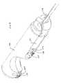
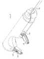
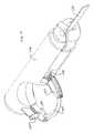
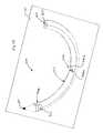
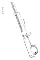
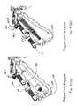
- FIG. 1For purposes of illustration and not limitation, as embodied herein, an exemplary embodiment of a suturing device 1000 is illustrated in FIG. 1 .
- Device 1000includes three regions, including a suture head 100 , an intermediate region 500 , and a handle 600 . Each of these regions is discussed in detail below.
- FIGS. 2-3illustrate device 1000 with certain portions removed.
- FIG. 2illustrates device 1000 with a needle loader removed (discussed in further detail below), while FIG. 3 illustrates device 1000 with certain portions of the handle housing removed.
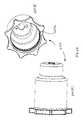
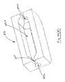
- Suture head 100For purposes of illustration, and not limitation, suture head 100 , separated from the remainder of device 1000 , is illustrated in FIG. 4 .
- Suture head 100includes a proximal end 102 , a distal end 104 , and is formed by the cooperation of three main housing components ( 106 , 108 , 112 ) that define a gap 110 for receiving tissue of a patient to be sutured together.
- Suture head 100is adapted and configured to direct a semi-circular needle ( 300 , 350 , 400 ) about a semicircular track and across gap 110 to form a series of sutures through tissue to be sutured.
- suture head 100Prior to advancing needle across gap 110 , suture head 100 must be converted from a delivery configuration to a deployed configuration. As illustrated in FIG. 4 and FIG. 5 , suture head 100 is initially provided in a compact form having a predetermined transverse dimension, or diameter, ⁇ .
- This transverse dimension, ⁇can be any desired dimension, and is preferably about 5 millimeters.
- the dimension ⁇is preferably selected so that suture head 100 can pass through a standard 5 mm trocar into a patient's abdomen, for example, during a laparoscopic surgical procedure.
- FIG. 5shows suture head 100 from the opposite angle as compared to FIG. 4 , including pivot boss 114 , which mates with intermediate portion 500 of device 1000 .
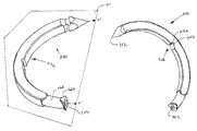
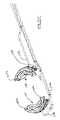
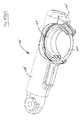
- Suture head 100is illustrated in deployed configuration in FIG. 6 .
- proximal guide 120 and distal guide 130are moved outwardly from their nested position defined by housing components 106 , 108 , discussed in further detail below.
- guides 120 , 130define a circular needle path or track 140 that lies in a plane P that is parallel to a longitudinal axis X of device 1000 .
- leading tip 302 of needle 300is advanced slightly by virtue of being dragged along by virtue of a pawl 125 in proximal guide 120 engaging a notch 306 disposed along an interior surface of needle 300 , discussed in detail below.
- needle 300can then be advanced through track by advancing pawl 160 to a distal extremity along its path of reciprocation.
- FIG. 7illustrates needle 300 spanning the gap 110 , wherein needle 300 , being about 180° in arcuate extent, is essentially located outside of the enclosure defined by housing segments 106 , 108 , 112 .
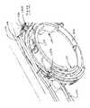
- FIGS. 8-10illustrate the functionality of suture head 110 from the opposite side of the head.
- FIG. 8illustrates suture head 100 in a delivery configuration with the guides 120 , 130 retracted.
- engagement pawl 160is withdrawn to a position proximal to the needle 300 , and the trailing end 304 of needle 300 is visible.
- FIG. 9illustrates suture head in a deployed configuration wherein guides 120 , 130 are deployed.
- distal guide 130defines an arcuate recess 135 that receives the pawl 160 at the distal extremity of its reciprocating movement, best observed in FIG. 10 .
- notch 158 in drive member 150is advanced in a distal direction as is pawl 160 .
- FIGS. 11(A)-11(D)illustrate the structure of the engagement pawl 160 .
- Pawl 160includes a housing 166 attached (e.g., welded) to the distal end 154 of drive member 150 .
- Housing 166is preferably a metallic tubular structure, and houses a pawl spring 164 biased between a movable pin 168 and cap portion 162 .
- Cap 162is preferably attached to housing 166 , such as be welding.
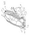
- FIG. 12illustrates suture head 100 with cover portion 106 removed, revealing the reciprocating guide path followed by drive member 150 and pawl 160 , as well as guides 120 , 130 .
- Guides 120 , 130are advanced from the delivery configuration to the deployed configuration by four advancement wires, cables or filaments, 172 , 174 , 176 , 178 that are directed around a series of bosses in housing portion 106 , discussed below.
- each guide 120 , 130includes crimps 102 a , 120 b , 130 a , 130 b that integrally form a end of each of the guides 120 , 130 .
- Each crimpincludes passages formed therein for receiving an end of wires 172 - 178 .
- Wires 172 - 178can take any suitable form, most preferably multi-strand 300 series Stainless Steel cables 0.009′′ in diameter. These ends are then crimped, adhered or otherwise attached to the crimps. Then by applying tension to one wire in each pair attached to each guide, the guides 120 , 130 are pulled into or out of the suture head 100 .
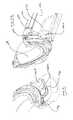
- FIG. 13illustrates the guides 120 , 130 in a deployed condition and does not display wires 172 - 178 simply for purposes of clarity.
- FIG. 14illustrates drive member 150 with pawl 160 at the full distal extent of its travel, riding within groove 135 in the side of guide 130 .
- the elevation 130 e of wall 130 dcan be increased and can be thickened to coincide with groove 135 to provide an enhanced bearing surface for pawl 160 .
- Stopsare preferably provided in the form of raised surfaces on guides 120 , 130 and the housing components to help prevent guides 120 , 130 from falling out of suture head.
- FIG. 14illustrates the spatial relationship of drive member 150 with respect to needle with other device components removed.
- FIG. 16illustrates the relative positions of needle 300 with respect to antirotate springs 115 and drive pin 168 housed within pawl 160 .
- pin 168includes a distal face 168 a that contacts a body of the needle, a circumferential generally cylindrical face 168 b , the distal extremity of which also contacts a surface of a notch in needle 100 , or the distal end 304 of needle, a proximal face 168 d that contacts pawl spring 164 , an enlarged head portion 168 c , and a circumferential distal face 168 e that contacts with a narrowed portion of the housing 166 of pawl 160 that prevents pin 168 from falling out of housing 166 .
- FIGS. 18-21are additional views of suture head 100 showing a progressive removal of components.
- FIG. 18shows the suture head 100 in tact
- FIGS. 19-20shows the positioning of bosses 106 a , 106 b , 106 c on housing portion 106 that define bearing points for guide cables 172 , 174 , 176 , 178 (not shown).
- Spacers 106 dmay also be provided to maintain a desired distance between housing components 106 , 108 to permit the movement of components within suture head 100 , and can also act as bearing surfaces for wires 176 , 178 ( FIG. 29 ).
- FIGS. 20-21illustrate removal of guard 109 which provides inner support for guides 120 , 130 to bear against. Guides 120 , 130 ride in arcuate channels defined by the cooperation of components 106 , 108 and 109 .
- FIG. 22illustrates proximal and distal guides 120 , 130 in the same spatial relationship as in FIG. 21 .
- Views of the proximal guide 120are depicted in FIGS. 23(A)-23(B) .
- Guides 120 , 130are preferably made from a metallic material by assembling a series of metallic subcomponents, such as by laser welding, and are unitary and integral once assembled. Guides can be thought of as having a “top” face that faces the drive member 150 , and a bottom “face” that faces housing portion 108 .
- Proximal guide 120defines a curved channel 125 in the top face 122 thereof.
- Proximal guide 120further defines a lower face 124 , having a groove 124 b defined therein, an inner face 126 that bears against the inner surface of guard 109 and an outer face 128 that bears against housing components 106 , 108 .
- distal guide 130defines a curved channel 135 in the top face 132 thereof for guiding the pawl 160 .
- Distal guide 130further defines a lower face 134 , having a groove 134 b defined therein, an inner face 136 that bears against the inner surface of guard 109 and an outer face 138 that bears against housing components 106 , 108 .
- FIGS. 25-32illustrate the cooperation between wires/filaments 172 - 178 and guides 120 , 130 .
- wires/filaments 172 , 174 , 176 and 178cooperate with bosses 106 a , 106 b , 106 c and the other components of suture head 100 to permit guides 120 , 130 to be selectively advanced and retracted.
- Wire 178terminates in crimp 130 b of guide 130 .
- Applying tension to wire 178which wraps around boss 106 a ( FIG. 28 ) results in guide 120 being advanced out of the suture head 100 .
- applying tension to wire 176which terminates in crimp 130 a of guide 130 ( FIG.
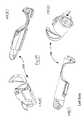
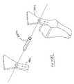
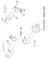
- FIGS. 33-37illustrate an embodiment of a needle loader 180 that is configured for loading a suturing needle ( 300 , 350 , 400 ) into suture head 100 .
- Needle loader 180has two main components, including a main body portion 182 and an advancement portion 184 .
- Pin 184 a of advancement portionis received in opening 182 a of main body portion 182 .
- Main body portion 182defines a groove 182 f for receiving a suturing needle ( 300 , 350 , 400 ).
- Main body portion 182includes a central portion 182 d and clip portions 182 c , 182 e that fit over suture head 100 . If desired, clip portions 182 c , 182 e may be adapted to snap fit over suture head 100 .
- a distal stop plate 182 bis provided to facilitate axial alignment between loader 180 and suture head 100 .
- Advancement portion 184rotates within opening 182 a of main body portion 182 , and further includes a needle pushing arm 186 .
- a needleis situated within track 184 f with suturing material attached to the trailing end, as discussed herein.
- the loader 180is then snapped onto suture head.
- Arm 186is preferably situated at this time proximate the trailing end of the needle. Arm 186 is then rotated such that needle ( 300 , 350 , 400 ) is advanced into the needle track 140 .
- needle ( 300 , 350 , 400 )can be advanced back into the needle loader 180 , by virtue of the fact that arm 186 is dimensioned to pass through the grooves 124 b , 134 b of proximal guide 120 and distal guide 130 , respectively.
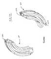
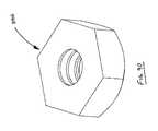
- FIGS. 38-40illustrate a first embodiment of a suturing needle 300 .
- Needle 300includes an arcuate body defined by a leading end 302 , a trailing end 304 and a generally toroidal surface 305 .
- Needle 300includes a plurality of notches 306 , 308 , 310 formed therein, as well as an opening 312 in trailing end 304 for receiving an end of a length of suturing material 312 a .
- Notches 306 , 308are located on an inner radial region 322 of needle, while notch 310 has a projection that lies within a plane P′ that is defined by the central curved axis X′ of the needle.
- Notch 310includes a first portion 310 a that is generally perpendicular to the plane P′ and a portion 310 b that generally lies in plane P′, and a sloped portion 310 c .
- the notches 306 , 308have projections that are generally perpendicular to the plane P′.
- Notches 308 , 306have first portions 306 a , 308 a that are generally parallel to a cross section of the needle in that location, and sloped portions 306 b , 308 b that are angled (such as by an angle of 60 degrees) with respect to portions 306 a , 308 a .
- Notches 308 , 310intersect to facilitate the function of the particular embodiments of suturing head 100 , 100 ′ described herein.
- FIGS. 41-44illustrate a second embodiment of a suturing needle 350 .
- Needle 350includes an arcuate body defined by a leading end 352 , a trailing end 354 and a generally toroidal surface 355 .
- Needle 350includes a plurality of notches 356 , 358 , 360 formed therein, as well as an opening 362 in trailing end 354 for receiving an end of a length of suturing material.
- Notches 356 , 358are located on an inner radial region 372 of needle, while notch 360 has a projection that lies within a plane P′ that is defined by the central curved axis X′ of the needle.
- Notch 360includes a first portion 360 a that is generally perpendicular to the plane P′ and a portion 360 b that generally lies in plane P′, and a sloped portion 360 c .
- the notches 356 , 358have projections that are generally perpendicular to the plane P′.
- Notches 358 , 356have first portions 356 a , 358 a that are generally parallel to a cross section of the needle in that location, and sloped portions 356 b , 358 b that are angled (such as by an angle of 60 degrees) with respect to portions 356 a , 358 a .
- Notches 358 , 360intersect to facilitate the function of the particular embodiments of suturing head 100 , 100 ′ described herein.
- Needle 350further includes a generally square cross-section having a rounded portion 366 and a tail portion 364 , also having a round cross section.
- the needle bodyincludes a portion with a round cross section 366 that separates a main portion of the needle with a generally square cross section from a tail portion 364 with a generally square cross section. It is believed that using a needle with a square cross section helps the needle 350 cross the gap 110 of suture head and re-enter suture head with superior alignment as compared to needle 300 .
- FIG. 45illustrates a third embodiment of a suturing needle 400 .
- Needle 400includes an arcuate body defined by a leading end 402 , a trailing end 404 and a generally toroidal surface 405 .
- Needle 400includes a plurality of notches 406 , 408 , 410 formed therein, as well as an opening 412 in trailing end 404 for receiving an end of a length of suturing material.
- Notches 406 , 408are located on an inner radial region 422 of needle, while notch 410 has a projection that lies within a plane P′ that is defined by the central curved axis X′ of the needle.
- the notches 406 , 408 , 410are generally similar to those described with respect to needle 300 .
- needles 300 , 400The principal difference between needles 300 , 400 are the addition of an additional notch 415 cut into the needle proximate its trailing end 404 .
- Notch 415has a projection in the plane P′ and is shaped to receive the housing 166 of the pawl 160 . It is believed that using a needle with notch 415 helps the needle 400 cross the gap 110 of suture head and re-enter suture head with superior alignment as compared to needle 300 .
- FIG. 46illustrates a fourth embodiment of a suturing needle 450 .
- Needle 450is essentially the same as needle 300 , except that it further includes an arcuate keel 475 , or raised surface, along its length.
- Keel 475is adapted and configured to ride in grooves 124 b , 134 b of guides 120 , 130 to stabilize the needle 450 as it crosses the gap 110 of suture head and re-enters suture head with superior alignment as compared to needle 300 .
- FIGS. 47(F) - 55illustrate aspects of an alternative embodiment of a suture head 100 ′ made in accordance with the disclosure.
- the principal difference between suture head 100 and suture head 100 ′lies in the path of travel of the drive element 150 .
- Embodiment 100 of suture headincludes a drive member 150 that defines a narrowed, or notched region 158 , as illustrated in FIG. 12 , for example.
- notched region 158is located to coincide with bosses 106 W, 108 W ( FIGS. 47(A)-47(D) ) when pawl 160 is located at the distal extremity of its range of motion within groove 135 of distal guide 130 .
- drive member 150extends into groove 125 of proximal guide 120 ( FIG. 14 ).
- narrowed region 158permits the drive member 150 to travel along an upper path above bosses 106 W, 108 W when advancing distally, and slip past bosses 106 W, 108 W when region 158 aligns with the bosses, thus permitting drive member 150 and pawl 160 to move proximally along a lower path below bosses 106 W, 108 W.
- Housing portion 112is illustrated in FIG. 47(E) .
- drive member 150should ideally be metallic.
- member 150is made from hardened stainless steel that has been heat treated to HR 900, and may have a chromium coating, such as an Armoloy ME 92® coating commercially available from ME-92® West/Armoloy® of Illinois, 118 Simonds Avenue, DeKalb, Ill. 60115, (815) 758-6691.
- member 150is 17-7 PH Stainless steel, condition “C” that is then hardened to condition CH900, and then coated with a ME 92® coating.
- the ME-92® coatingis applied after 900 Heat Treatment.
- the sequence of operations in manufacturing member 150includes providing 17-7 PH strip stock material that is machined to size by any number of known methods (e.g., electrical discharge machining (“EDM”), shearing, milling, etc.).
- EDMelectrical discharge machining
- the drive ribbonis heat treated, and then cleaned to remove heat treatment surface oxidation, and the ME-92® coating is then applied.
- 17-7PH condition “A” materialcan be heat treated to RH950.
- the drive member 150can be made, for example, from shape memory material such as nickel-titanium alloys sold under the trade name of NITINOL® and the like.
- member 150is made from a polymeric material.
- member 150can include polyethylene terephthalate material or nylon material of high strength.
- member 150can be comprised of a bundle of wires or filaments, a single wire or filament, or any material in any configuration that permits driving the needle around the needle track.
- suture head 100including the needle ( 300 , etc.) are preferably formed by metal injection molding (“MIM”) techniques, as are known in the art from various materials, preferably stainless steel. In accordance with a preferred embodiment, 17-4 PH stainless steel alloy is preferably used.
- Device 1000is preferably a disposable device, and handle components are preferably made from injection molded plastic wherever desirable.
- FIGS. 47(F) - 55A further embodiment of a suture head 100 ′ is set forth in FIGS. 47(F) - 55 .
- the principal difference between suture head 100 ′ and suture head 100is that the drive member 150 in suture head 100 ′ follows a single path during reciprocation, in contrast with the alternating path of embodiment 100 .
- FIG. 47(F)illustrates suture head 100 ′ including a needle 300 with guides 120 ′, 130 ′ in a deployed configuration. Guides 120 ′ 130 ′ are only partially represented and are not depicted including crimps at their extremities for mating with deployment or retraction cables as with embodiment 100 discussed earlier.
- Suture head 100 ′defines a guide path 153 ′ between housing components 106 ′, 112 ′ ( FIG.
- FIG. 48further illustrates an alternate path 1001 that can be traversed by drive member 150 ′ by modifying components 106 ′, 112 ′ by removing material 112 a ′ that acts as a pawl stop and adding material 106 ′ b in component 106 ′ to act as a new pawl stop.
- the end resultis a different angle of incidence for the drive member 150 .
- FIG. 49illustrates the “left” housing component 108 ′ from various angles
- FIGS. 50(A)-50(E)illustrate the “right” housing component from various angles
- Apparent from the figuresis the path 153 ′ followed by the drive member 150 ′ and pawl 160 ′ (not shown).
- drive member 150 ′ and pawl 160 ′can be substantially identical to embodiments 150 , 160 , but need not have the notched region 158 , as a single path for traversal of pawl 160 ′ is defined by cooperation of housing components 106 ′, 108 ′.
- Guard 109 ′is illustrated in FIGS.
- FIG. 52illustrates the spatial relationship of guides 120 ′, 130 ′ with respect to pin face 168 a ′ and pawl 160 ′ in their two respective locations, for purposes of illustration only.
- FIGS. 53(A)-53(D)illustrate various views of housing portion 112 ′.
- guides 120 ′, 130 ′which are substantially identical to guides 120 , 130 ) with respect to pawl 115 ′ and further illustrates guide stops 117 ′, which help guides 120 ′, 130 ′ stop in a predetermined location when in an undeployed condition.
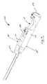
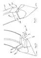
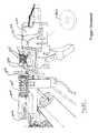
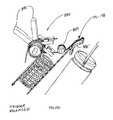
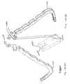
- FIGS. 56-59illustrate aspects of the intermediate region 500 of device 1000 .
- Intermediate region 500includes an elongate, preferably metallic tube 510 having a proximal end and a distal end 514 .
- Distal end 514 of tube 510is attached to a knuckle assembly 520 , which in turn is pivotally attached at pivot 114 to suture head 110 .
- a pulley 515is located at pivot 114 to serve as a bearing surface for adjoined articulation cables 532 , 534 and cables 532 , 534 are preferably affixed to pulley 515 to provide leverage for accomplishing articulation.
- Articulation cables 532 , 534can take any suitable form, most preferably multi-strand 300 series Stainless Steel cables that are 0.020′′ in diameter. By pulling on one of the articulation cables, the suture head 100 will articulate with respect to intermediate region 500 about the pivot 114 .
- Knuckle 520includes a proximal end 522 and a distal end 524 (in the form of a yoke 524 a , 524 b for receiving suture head 100 ) separated by an intermediate region 526 .
- Intermediate region 526defines a longitudinal channel 528 therethrough for receiving drive member 150 .
- member 150is attached to a pull rod 151 in this region, and the cross-sectional profile of channel 528 is adapted to accommodate such a geometry, as depicted in the Figures. Openings 523 are also defined for receiving members 532 , 534 . Moreover, openings 525 , 527 are also provided to permit passage of pull wires/cables 172 , 174 , 176 , 178 for controlling the movement of guides 120 , 130 .
- the proximal end of tubular member 510is attached to a roticulation mechanism that rotates the tube 510 and suture head 100 with respect to a handle 600 of the device, discussed below.
- the distal end 514 a of tube 510may be extended slightly to provide for tighter control of drive element 150 as it passes into intermediate region 500 .
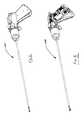
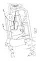
- handle 600 of device 1000is illustrated from FIGS. 60-122 .
- Handle 600includes many components and systems for operating suture head 100 , 100 ′.
- FIG. 61illustrates a head-on view of handle with tube 510 removed, illustrating roticulation handle 620 , wherein relative rotational motion of handle 620 with respect to handle 600 will cause the suture head 100 , 100 ′ to rotate with respect to handle 600 .
- FIG. 60depicts a rear view of handle 600 .
- FIG. 62depicts handle with roticulation handle 620 removed, and depicting proximal cable guide 606 , left tube collar 634 and right tube collar 632 .
- Tube collar portions 632 , 634cooperate to capture the proximal end 512 of tube 510 , which can be, for example and not limitation, a 5 mm nominal outside diameter stainless steel hypotube. Also illustrated is articulation handle 630 that can be used to articulate suture head 100 about its pivot point as discussed above.
- Housing 600includes two main housing halves including a right side 612 and a left side 614 .
- FIG. 63illustrates handle 600 with tube collars 632 , 634 removed.
- Proximal cable guide 606is anchored within hypotube, such as by interference fit. The longitudinal distance along tube 510 between the distal disc 606 b of proximal cable guide 606 and cable disc 648 ( FIGS.
- suture headhas a total angular range of motion of about 270 degrees with respect to handle 600 , desirably about 135 degrees in either direction from the home position illustrated in the Figures.
- Detents in roticulation handle 620are adapted and configured to engage with a pawl 614 g housed in an opening in left handle portion 614 ( FIG. 79(A) ).
- Tube collarsare essentially mirror images of each other (across a vertical centerplane of the device 1000 ) and cooperate to define a hollow, generally cylindrical interior for receiving proximal end 512 of tube 510 .
- lugs 632 a , 634 aare provided to mate with openings 518 near the proximal end 512 of tube 510 ( FIG. 69 ).
- Tube collarsalso define radially oriented detents 632 b , 634 b along their proximal faces to mate with raised portions 644 b on the distal face of roticulator plate 644 ( FIG. 68 ).
- Roticulator plate 644further includes a proximal portion 644 c having a square cross section for being received by the left and right housing side portions 612 , 614 .
- Roticulator plate 644is received in housing 614 between adjacent ribs 614 r ( FIG. 70 ) as is cable disc 648 .
- Cable disc 648( FIGS. 71-72 ) defines a circumferential groove 648 b about its periphery for mating with a rib 614 r as well as an annularly-shaped channel 648 a in its distal face for receiving a roticulator spring 646 .
- Spring 646is adapted and configured to urge roticulator plate into contact with detents 632 b , 634 b to facilitate stepwise rotational movement.
- cable disc 648further defines a plurality of openings 648 c therethrough to permit passage of cables/wires 172 , 174 , 176 , 178 , 532 , 534 and 551 .
- a cable path guide 650is provided for directing cables 172 , 174 , 176 , 178 , 532 , 534 through the handle 600 .
- guide 650provides a first set of guides 654 for guiding cables 172 , 174 , 176 , 178 , and a second set of guides, or bosses, 652 , 654 for directing cables 532 , 534 through the handle 600 .
- Grooves 658are provided in guide 650 for receiving ribs 612 r of right housing portion 612 ( FIG. 79(D) ).
- FIGS. 75-76illustrate a cutaway view of handle 600 wherein right housing portion 612 has been removed to permit view of interior components of handle 600 .
- FIG. 75illustrates trigger 700 , or actuator, in a locked position
- FIG. 76illustrates trigger 700 in a released position wherein the trigger can be depressed, thus advancing needle (e.g., 300 ) about needle track 140 .
- handleincludes trigger 700 , pull cable/ribbon 710 , trigger spring capsule 720 , trigger return spring 730 , pull cable 727 , pulley 750 and brake handle 800 for preventing articulation knob 810 from being rotated.
- stop surface 614 sis defined in left housing 614 to define a stop point for trigger 700 when trigger 700 is locked.
- Right housing 612includes a similar stop feature 612 s ( FIG. 79(D) ).
- Articulation knob 810( FIG. 77(E) ) includes a handle portion 812 , an elongate shaft 814 for engaging with brake rotate fitting 830 ( FIG. 83 ), and a distal portion 816 that is preferably threaded for receiving a hex nut 886 ( FIG. 90 ).
- Right and left handle cap portions 616 , 618FIGS.
- FIG. 77(A)-77(D)are provided with bosses 616 a , 618 a for receiving and supporting the edges 835 b of brake springs 835 ( FIG. 84 ).
- Bearing portion 835 a of brake springs 835bear against brake rotate fittings 830 , which in turn urges brake rotate fittings 830 against shaft 814 of knob 810 .
- Portion 814 of knob 810preferably includes a resilient layer or coating that can grip serrated portion 834 of fittings 830 , wherein rotation of the knob 810 causes the fittings 830 , and hence cables 532 , 534 to advance along a proximal-distal direction with respect to device 1000 , resulting in articulation of suture head 100 , 100 ′.
- FIGS. 78illustrates handle 600 with components 810 , 616 , 618 removed.
- FIGS. 79(A)-79(D)illustrate inner and outer views of left and right handle portions 612 , 614 .
- FIGS. 80-81illustrate the inner workings of handle 600 with both handle portions 612 , 614 removed with the trigger 700 locked, and released, respectively.
- FIG. 82illustrates a close up view of the inner workings of handle 600 , showing the upper brake pad 820 removed, fully revealing the positioning of fittings 830 and springs 835 with the trigger 700 released.
- FIGS. 83-85further illustrate fittings 830 , spring 835 and spring 845 .
- FIGS. 86(A)-86(B)illustrate the movement of shuttle 888 ( FIGS. 99(A)-99(B) ), which moves proximally upon the release of trigger 700 .
- Proximal movement of shuttle 888prevents handle 892 r from being articulated, which, in turn, prevents guides 120 , 130 from being withdrawn into suture head 100 , 100 ′ while trigger 700 is actuated, advancing the needle (e.g., 300 ) about circular needle track 140 , 140 ′.
- Components 830 , 835have been removed in FIG. 86 to better illustrate lower brake pad 850 .
- Brake pads 820 , 850are preferably made from resilient and somewhat compressible material, such as silicone.
- FIGS. 87(A)further illustrates lower brake pad 850
- FIGS. 87(B)-87(D)illustrate brake bracket 860
- Bracket 860defines a circular boss 862 thereon for receiving lower brake pad 850 , as well as brake handle components 882 , 884 , 884 a ( FIG. 91(B) ).
- FIGS. 88-89 (A)illustrate remaining inner workings of handle with brake pad removed ( FIG. 88 ) and further with pulley holder 840 and brake bracket 860 removed.
- 89(A)-89(B)further illustrates coupling knuckle 872 , which includes longitudinal openings 872 a having narrowed portions 872 c that are wide enough to permit passage of a cable 532 , 534 , but not wide enough to permit passage of cable terminations 874 ( FIG. 91 ). Opening 872 b , in contrast, is large enough to permit terminations 874 to pass into knuckle 872 , thus joining cable 532 to cable 534 , and providing a closed loop to facilitate articulation by way of articulation and brake control 800 .
- Brake trigger 884can be pulled, causing a camming effect of by moving an upper portion of handle component 882 (and its counterpart on the left side of the device) into contact with lower brake pad 850 , causing the brake pad 850 to compress components 830 between the upper and lower brake pads 820 , 850 .
- FIGS. 92-102illustrate aspects of the operation and control for the guides 120 , 130 as well as the locking mechanism for trigger 700 .
- Guides 120 , 130are deployed or withdrawn by rotating handles 892 .
- Cables 172 - 178are routed over guide 885 , which is held in place by housing components 612 , 614 and are split up into two pairs of wires, wherein one set of wires is directed downwardly around spring loaded pulleys 894 a , 896 a and routed up to handles 192 where all four cables, 172 , 174 , 176 , 178 are held in place in openings 892 b in handles 892 by tapered pins 893 .
- the other pair of cablesis routed about guide 887 directly into handles 892 .
- Guide 885( FIG. 93(B) ) is a generally curved planar member having a plurality of cable guides 885 a , wherein the cables 172 - 178 bear over its upper surface on their route to handles 892 .
- FIG. 93(A)illustrates guides 887 and 885 in situ in relation to other internal components of handle 600 .
- Guide 887( FIGS. 93(C)-93(D) ) include bosses 887 a to be received by housing portions 612 , 614 , and grooves 887 b defined by fins 887 c for routing cables/wires.
- Handles 892include grips 892 a and grooves 892 c and channels 892 d for directing cables/wires into openings 892 b ( FIGS. 94(A) - 94 E). Both handles 892 can be essentially identical in form.
- Guide handles 892also play a role in releasing trigger lock 780 , thereby permitting trigger 700 to actuate the movement of needle (e.g., 300 ).
- trigger lock 780is attached to a cable at ferrule 781 , which is disposed in opening 783 at bifurcation 782 of trigger lock ( FIGS. 95(C)-95(D) ).
- Trigger lock 780is slidably disposed on a cylindrical rail 786 , and is biased toward a locked position by spring 787 .
- a bifurcation 784 at the opposite end of trigger lock 780is adapted and configured to interlock with trigger 700 .
- FIGS. 97-101further illustrate additional features of the actuation system for guides 120 , 130 with progressively additional components removed to better illustrate other components, and their relative positions.
- FIG. 102further illustrates additional aspects and views of components 840 , 894 , 896 .
- FIGS. 103-113illustrate aspects of the operation of reciprocating trigger mechanism 700 .
- FIG. 103illustrates the relative positions of trigger 700 , pull cable/ribbon 710 , trigger spring capsule 720 , trigger return spring 730 , pull cable 727 and pulley 750 .
- FIG. 103removes components 786 , 787 and handle 700 to reveal ferrule 752 , which is fixed to a terminal end of pull cable 727 and resides within an opening 701 within handle 700 ( FIG. 105 ).
- Trigger 700is further illustrated in FIGS. 106(A)-106(B) from two additional angles, showing bifurcated yoke 702 proximate the top end of trigger 700 .
- Yoke cap 704is received in trigger handle 700 by securing studs 704 a into holes 700 a by interference fit and/or ultrasonic welding, adhesive or the like. Yoke 702 and yoke cap 704 define openings 702 a , 704 a therein for receiving bosses 888 a of shuttle link 888 ( FIG. 99(B) ).
- FIG. 107(A)illustrates the interior of capsule 720 , revealing clutch spring 724 .
- FIGS. 107(B)-107(C)illustrate housing portion 720 a , which mates with housing portion 720 b . Housing portion 720 b is an identical mirror image of portion 720 a , so only 720 a is illustrated. Clutch spring 724 is removed in FIG.
- FIG. 109illustrates the assembly with spring 730 and housing portion 720 b removed.
- FIG. 110illustrates a closeup of the connection of drive member 710 to assembly 720 , showing the manner in which tabs 711 , 712 at proximal end of drive member 710 are bent and inserted through the slot 721 a in washer plate 721 .
- O-rings 720which may be silicone or other suitable material, are illustrated in FIGS. 104 and 109 .
- O-rings 729provide a seal against housing segments 612 , 614 .
- Ferrule 723is secured to cable 727 .
- FIGS. 111-113provide closer views of ferrule 723 , washer plate 721 and proximal end of member 710 , respectively.
- FIGS. 114-120further illustrate the connections between drive member 710 and drive members 150 / 551 .
- proximal drive memberwhich can include ribbon-element 150 described above attached to intermediate cable section 551 in intermediate region 500 , is received by a ferrule 910 which is affixed in place after termination 930 is attached, and positioned into cavity 922 in coupling by passing cable/rod 551 through slot 924 in coupling 920 .
- Rounded portion 932 of terminationfaces distally, permitting movement between member 551 and coupling 920 .
- termination 930defines a passage 936 therethrough for receiving cable 551 , and defines a generally cylindrical proximal section 934 .
- Ferrule 910defines a passage 912 therethrough for receiving cable 551 , and a transverse opening 914 therethrough, such as for receiving brazing or soldering material or other material for holding ferrule in place on cable 551 .
- Coupling 920includes a proximal face 922 a , a distal face 928 and a bore 922 therethrough.
- threaded male fitting 940is received within threaded opening 922 of coupling, and receives a retaining hex nut 950 thereon.
- Proximal end 943 of fitting 940faces proximally, and defines a cavity 946 therein for receiving distal tip 717 of drive ribbon/cable 710 .
- FIGS. 121-122illustrate torsion spring 960 and guide spring 970 and their positioning with respect to the other components within handle 600 .
- Springs 960 , 970are a part of the control mechanism for deploying and retracting guides 120 , 130 .
- Return spring 895 , 897is illustrated in FIG. 121(C) .
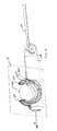
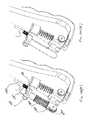
- FIG. 123illustrates a cutaway view of suture head 100 with needle 300 disposed therein in a delivery configuration with guides 120 , 130 retracted. Needle 300 is wholly contained within device 1000 , and pawl spring 115 b prevents needle 300 from moving in a counterclockwise direction. Similarly, pawl spring 115 a is biased against the inner circumferential surface 322 of needle, tending to prevent needle from moving in a clockwise direction. As set forth in FIGS.
- the drive system of the device 1000is adapted and configured to advance the needle 300 in multiple 360° revolutions about the needle track when the needle track is in a deployed condition. It is further evident that the needle track is about 180° in extent prior to deployment, and greater than 180° in angular extent after deployment.
- FIG. 124illustrates the initial deployment of guides.
- Pawl 115 ais dragged along surface 322 of needle 300 until it engages with notch 308 and pawl 115 b engages with notch 306 .
- Guidesare then fully retracted in FIG. 125 , and pawl 115 a situated in guide 120 drags needle 300 in a clockwise direction to present it for suturing.
- Pawl 160meanwhile is advanced along its arcuate track along guides 120 , 130 to its distalmost extent, causing notch 158 in the drive member 150 to align with boss 108 a , and pawl 115 b bears against surface 122 of needle 300 .
- Region 158slips past bosses 106 a , 108 a as before, and pawl 160 and the leading tip 302 of needle are pulled along the arcuate needle track 140 , resulting in the needle being returned to its starting point, as illustrated in FIG. 128 .
- FIG. 129illustrates guides 120 , 130 in partial retraction such that needle is moved counterclockwise until notch 306 meets with pawl 115 b .
- FIG. 130illustrates guides 120 , 130 retracted even further, illustrating how pawl 115 a is pulled out of notch 308 and is dragged along surface 322 of needle. Further counterclockwise movement of needle 300 is prevented by pawl 115 b being locked into notch 306 .
- FIG. 129illustrates guides 120 , 130 in partial retraction such that needle is moved counterclockwise until notch 306 meets with pawl 115 b .
- FIG. 130illustrates guides 120 , 130 retracted even further, illustrating how pawl 115
- 131illustrates suture head 110 once again in delivery or removal configuration with guides 120 , 130 fully withdrawn.
- a deviceis provided herein that can rotate the disclosed needle through 180°, 360°, or any further multiple of 180° as desired. If desired, the angular increments of advancement could be increments of more or less than 180° as desired.
- the suturing devices of the presently disclosed embodimentscan be used for laparoscopic procedures, including but not limited to laparoscopic colostomy, colectomy, adrenalectomy, splenectomy, repair of paraesophageal hernia, inguinal hernia repair, ventral hernia repair, Nissen fundoplication, liver lobectomy, gastrectomy, small bowel resection, treatment of small bowel obstruction, distal pancreatectomy, nephrectomy and gastric bypass.
- laparoscopic proceduresincluding but not limited to laparoscopic colostomy, colectomy, adrenalectomy, splenectomy, repair of paraesophageal hernia, inguinal hernia repair, ventral hernia repair, Nissen fundoplication, liver lobectomy, gastrectomy, small bowel resection, treatment of small bowel obstruction, distal pancreatectomy, nephrectomy and gastric bypass.
- laparoscopic proceduresincluding but not limited to laparoscopic colos
- the abdomenis insufflated with gas to create a working space for the user.
- gasAny gas known to those skilled in the art including, but not limited to, nitrogen or carbon dioxide, can be used.
- Access portalsare established using trocars in locations to suit the particular surgical procedure.
- a variety of surgical instrumentsmay then be inserted into the body through these access ports/cannulas.
- the userthen introduces the distal end portion of the suturing device into a cannula, and then articulates the suture head assembly (e.g., 100 , 100 ′).
- the suture head assemblyis then positioned relative to the tissue/vessel to be sutured together, and the user preferably locks the suture head assembly in place.
- the userthen, through manipulation of the suturing device, positions a plurality of separated tissue segments into the opening defined at the distal end portion of the suture head assembly.
- the userusing only one hand, may manipulate the device while actuating the handle to close an incision with a continuous suture whose stitches may be individually tensioned precisely and uniformly along the length of the suture similar to suturing done by hand in the conventional way.
- the usermay employ a single suture which would extend the entire length of the incision or multiple sutures.
- the suturing deviceenables the user to lay down a running stitch or interrupted stitch to close the tissue incision in a time efficient manner.
- the minimalized structural design of the suture head assemblyenables the user to have a clear, unobstructed view of the suturing needle during advancement through the tissue segments during the course of a suturing operation, thereby enabling precise placement of the suturing device to provide uniform sutures and precluding the risk of tearing tissue by placement too close to the edge of the incision.
- the suturing deviceis then advanced a short distance along the incision and the aforementioned operation is repeated to produce another stitch comprising the suturing material or thread.
- the usermay continue to manipulate the suturing device, alternately advancing and actuating rotation of the needle about an axis that is generally parallel to the direction of advancement to create a continuous suture which may extend through the entire length of the incision or a series of interrupted stitches.
- the stitchis tightened by exerting a pull on the suturing material or thread so that the resultant suture is tensioned uniformly along the length of the incised tissue segments. Therefore, a tight closure of the segments is accomplished and bleeding and tearing of tissue are minimized.
- the usercan use a needle grasper to tighten and knot the formed stitches.
Landscapes
- Health & Medical Sciences (AREA)
- Life Sciences & Earth Sciences (AREA)
- Surgery (AREA)
- Heart & Thoracic Surgery (AREA)
- Engineering & Computer Science (AREA)
- Biomedical Technology (AREA)
- Nuclear Medicine, Radiotherapy & Molecular Imaging (AREA)
- Medical Informatics (AREA)
- Molecular Biology (AREA)
- Animal Behavior & Ethology (AREA)
- General Health & Medical Sciences (AREA)
- Public Health (AREA)
- Veterinary Medicine (AREA)
- Surgical Instruments (AREA)
Abstract
Description
Claims (21)
Priority Applications (20)
| Application Number | Priority Date | Filing Date | Title |
|---|---|---|---|
| US13/204,820US9775600B2 (en) | 2010-10-01 | 2011-08-08 | Devices and methods for minimally invasive suturing |
| EP12822057.1AEP2741680A4 (en) | 2011-08-08 | 2012-08-08 | Devices and methods for minimally invasive suturing |
| JP2014525116AJP6016921B2 (en) | 2011-08-08 | 2012-08-08 | Device for minimally invasive sutures |
| PCT/US2012/049979WO2013022959A2 (en) | 2011-08-08 | 2012-08-08 | Devices and methods for minimally invasive suturing |
| CN201280038779.5ACN103889343B (en) | 2011-08-08 | 2012-08-08 | Apparatus and methods for minimally invasive suturing |
| CN201710957876.9ACN107736903B (en) | 2011-08-08 | 2012-08-08 | Apparatus and method for minimally invasive suturing |
| KR1020147002704AKR101606894B1 (en) | 2011-08-08 | 2012-08-08 | Devices and methods for minimally invasive suturing |
| AU2012294422AAU2012294422B2 (en) | 2011-08-08 | 2012-08-08 | Devices and methods for minimally invasive suturing |
| KR1020167007550AKR101868007B1 (en) | 2011-08-08 | 2012-08-08 | Devices and methods for minimally invasive suturing |
| HK14111988.5AHK1198508B (en) | 2011-08-08 | 2012-08-08 | Devices and methods for minimally invasive suturing |
| AU2015238863AAU2015238863B2 (en) | 2011-08-08 | 2015-10-08 | Devices and methods for minimally invasive suturing |
| JP2016187970AJP6333333B2 (en) | 2011-08-08 | 2016-09-27 | Apparatus and method for minimally invasive sutures |
| US15/377,562US9675339B2 (en) | 2004-09-20 | 2016-12-13 | Devices and methods for minimally invasive suturing |
| US15/610,277US9962151B2 (en) | 2010-10-01 | 2017-05-31 | Devices and methods for minimally invasive suturing |
| JP2018006295AJP2018086279A (en) | 2011-08-08 | 2018-01-18 | Suturing device |
| US15/942,509US10792031B2 (en) | 2010-10-01 | 2018-03-31 | Devices and methods for minimally invasive suturing |
| US16/236,966US10881392B2 (en) | 2010-10-01 | 2018-12-31 | Devices and methods for minimally invasive suturing |
| JP2019226285AJP7137551B2 (en) | 2011-08-08 | 2019-12-16 | Device for minimally invasive suturing |
| US17/100,922US11986179B2 (en) | 2010-10-01 | 2020-11-22 | Devices and methods for minimally invasive suturing |
| US18/490,860US20240050086A1 (en) | 2010-10-01 | 2023-10-20 | Devices and methods for minimally invasive suturing |
Applications Claiming Priority (3)
| Application Number | Priority Date | Filing Date | Title |
|---|---|---|---|
| US38864810P | 2010-10-01 | 2010-10-01 | |
| US12/909,606US7993354B1 (en) | 2010-10-01 | 2010-10-21 | Devices and methods for minimally invasive suturing |
| US13/204,820US9775600B2 (en) | 2010-10-01 | 2011-08-08 | Devices and methods for minimally invasive suturing |
Related Parent Applications (1)
| Application Number | Title | Priority Date | Filing Date |
|---|---|---|---|
| US12/909,606Continuation-In-PartUS7993354B1 (en) | 2004-09-20 | 2010-10-21 | Devices and methods for minimally invasive suturing |
Related Child Applications (1)
| Application Number | Title | Priority Date | Filing Date |
|---|---|---|---|
| US15/377,562ContinuationUS9675339B2 (en) | 2004-09-20 | 2016-12-13 | Devices and methods for minimally invasive suturing |
Publications (2)
| Publication Number | Publication Date |
|---|---|
| US20120143248A1 US20120143248A1 (en) | 2012-06-07 |
| US9775600B2true US9775600B2 (en) | 2017-10-03 |
Family
ID=46162937
Family Applications (7)
| Application Number | Title | Priority Date | Filing Date |
|---|---|---|---|
| US13/204,820ActiveUS9775600B2 (en) | 2004-09-20 | 2011-08-08 | Devices and methods for minimally invasive suturing |
| US15/377,562ActiveUS9675339B2 (en) | 2004-09-20 | 2016-12-13 | Devices and methods for minimally invasive suturing |
| US15/610,277ActiveUS9962151B2 (en) | 2010-10-01 | 2017-05-31 | Devices and methods for minimally invasive suturing |
| US15/942,509Active2031-05-31US10792031B2 (en) | 2010-10-01 | 2018-03-31 | Devices and methods for minimally invasive suturing |
| US16/236,966Active2031-04-04US10881392B2 (en) | 2010-10-01 | 2018-12-31 | Devices and methods for minimally invasive suturing |
| US17/100,922Active2031-11-12US11986179B2 (en) | 2010-10-01 | 2020-11-22 | Devices and methods for minimally invasive suturing |
| US18/490,860PendingUS20240050086A1 (en) | 2010-10-01 | 2023-10-20 | Devices and methods for minimally invasive suturing |
Family Applications After (6)
| Application Number | Title | Priority Date | Filing Date |
|---|---|---|---|
| US15/377,562ActiveUS9675339B2 (en) | 2004-09-20 | 2016-12-13 | Devices and methods for minimally invasive suturing |
| US15/610,277ActiveUS9962151B2 (en) | 2010-10-01 | 2017-05-31 | Devices and methods for minimally invasive suturing |
| US15/942,509Active2031-05-31US10792031B2 (en) | 2010-10-01 | 2018-03-31 | Devices and methods for minimally invasive suturing |
| US16/236,966Active2031-04-04US10881392B2 (en) | 2010-10-01 | 2018-12-31 | Devices and methods for minimally invasive suturing |
| US17/100,922Active2031-11-12US11986179B2 (en) | 2010-10-01 | 2020-11-22 | Devices and methods for minimally invasive suturing |
| US18/490,860PendingUS20240050086A1 (en) | 2010-10-01 | 2023-10-20 | Devices and methods for minimally invasive suturing |
Country Status (1)
| Country | Link |
|---|---|
| US (7) | US9775600B2 (en) |
Cited By (5)
| Publication number | Priority date | Publication date | Assignee | Title |
|---|---|---|---|---|
| US11033262B2 (en) | 2006-01-27 | 2021-06-15 | Intuitive Surgical Operations, Inc. | Apparatus and method for tissue closure |
| US11253250B2 (en) | 2017-02-26 | 2022-02-22 | Intuitive Surgical Operations, Inc. | Apparatus and method for minimally invasive suturing |
| US11653912B2 (en) | 2019-12-12 | 2023-05-23 | Intuitive Surgical Operations, Inc. | Needle driver devices and related systems and methods |
| US11871969B2 (en) | 2021-03-03 | 2024-01-16 | Acustitch, Llc | System and method for osseous reconstruction and repair and implant device |
| US11986179B2 (en) | 2010-10-01 | 2024-05-21 | Intuitive Surgical Operations, Inc. | Devices and methods for minimally invasive suturing |
Families Citing this family (26)
| Publication number | Priority date | Publication date | Assignee | Title |
|---|---|---|---|---|
| US20230248355A1 (en)* | 2007-05-24 | 2023-08-10 | Intuitive Surgical Operations, Inc. | Apparatus and method for minimally invasive suturing |
| WO2013022959A2 (en)* | 2011-08-08 | 2013-02-14 | Endoevolution, Llc | Devices and methods for minimally invasive suturing |
| AU2015203325B2 (en)* | 2012-12-13 | 2016-11-03 | Ethicon Endo-Surgery, Inc. | Circular needle applier |
| US9398905B2 (en)* | 2012-12-13 | 2016-07-26 | Ethicon Endo-Surgery, Llc | Circular needle applier with offset needle and carrier tracks |
| US9125645B1 (en) | 2013-03-11 | 2015-09-08 | Ethicon Endo-Surgery, Inc. | Reciprocating needle drive without cables |
| US20150351749A1 (en) | 2014-06-06 | 2015-12-10 | Ethicon Endo-Surgery, Inc. | Needle Cartridge with Moveable Cover |
| USD771811S1 (en) | 2013-03-15 | 2016-11-15 | Ethicon Endo-Surgery, Llc | Suture tray |
| US9375212B2 (en) | 2014-06-06 | 2016-06-28 | Ethicon Endo-Surgery, Llc | Circular needle applier with cleats |
| US9554781B2 (en) | 2014-01-23 | 2017-01-31 | Lsi Solutions, Inc. | Minimally invasive surgical suturing device and method |
| USD745146S1 (en) | 2014-06-06 | 2015-12-08 | Ethicon Endo-Surgery, Inc. | Surgical suturing device |
| US10004490B2 (en) | 2014-06-06 | 2018-06-26 | Ethicon Llc | Force limited needle driver |
| US10022120B2 (en) | 2015-05-26 | 2018-07-17 | Ethicon Llc | Surgical needle with recessed features |
| US10149678B1 (en)* | 2015-06-17 | 2018-12-11 | Ethicon Llc | Suturing instrument with elastomeric cleat |
| USD800306S1 (en) | 2015-12-10 | 2017-10-17 | Ethicon Llc | Surgical suturing device |
| USD865964S1 (en) | 2017-01-05 | 2019-11-05 | Ethicon Llc | Handle for electrosurgical instrument |
| US11298122B2 (en) | 2018-06-07 | 2022-04-12 | EnVision Endoscopy, Inc. | Endoscopic suturing device with circular needle |
| USD895112S1 (en) | 2018-11-15 | 2020-09-01 | Ethicon Llc | Laparoscopic bipolar electrosurgical device |
| CN112089458A (en)* | 2019-05-30 | 2020-12-18 | 香港大学深圳医院 | Split surgical stapler |
| US20220257236A9 (en)* | 2019-06-06 | 2022-08-18 | EnVision Endoscopy, Inc. | Endoscopic suturing device |
| USD938031S1 (en)* | 2019-07-14 | 2021-12-07 | Telma Micro Needles Pvt. Ltd. | Undrilled needle |
| CN110584730B (en)* | 2019-08-28 | 2020-08-14 | 中国人民解放军陆军军医大学第一附属医院 | Pouch stitching device |
| WO2021046084A1 (en)* | 2019-09-06 | 2021-03-11 | Boston Scientific Scimed, Inc. | Endoscopic medical device with a needle passer and with a needle grasper |
| CN111481247B (en)* | 2020-04-20 | 2021-04-06 | 广西壮族自治区人民医院 | A stapler for gastroenteroscopy and its operation method |
| US20230165581A1 (en)* | 2020-04-27 | 2023-06-01 | Ping Wang | Suture device, treatment device with suture device, and treatment system |
| EP4231947A4 (en) | 2020-10-23 | 2024-10-02 | Envision Endoscopy, Inc. | ENDOSCOPIC SUTURE STRAP |
| CN120344203A (en)* | 2022-12-01 | 2025-07-18 | 波士顿科学国际有限公司 | Suture-based closure device |
Citations (186)
| Publication number | Priority date | Publication date | Assignee | Title |
|---|---|---|---|---|
| GB190818602A (en) | 1908-09-04 | 1909-09-06 | Frank Mitchell | Improvements in and relating to Surgical Stitching Instruments. |
| US1327577A (en) | 1919-03-11 | 1920-01-06 | Joseph S Turner | Surgical-needle holder |
| US1822330A (en) | 1930-01-13 | 1931-09-08 | Ainslie George | Suturing instrument |
| US2327353A (en) | 1940-12-12 | 1943-08-24 | Singer Mfg Co | Instrument for suturing |
| US2601564A (en) | 1950-07-08 | 1952-06-24 | David P Smith | Suturing device |
| US3197997A (en) | 1960-11-17 | 1965-08-03 | Leonard D Kurtz | Suture needle |
| US3311110A (en) | 1964-07-15 | 1967-03-28 | American Cyanamid Co | Flexible composite suture having a tandem linkage |
| US3344790A (en) | 1964-11-02 | 1967-10-03 | Richard L Dorner | Surgical suturing device with auxiliary spool-brake means |
| US3762418A (en) | 1972-05-17 | 1973-10-02 | W Wasson | Surgical suture |
| US3834599A (en)* | 1972-08-04 | 1974-09-10 | N Herr | Needle |
| US3835912A (en) | 1973-06-25 | 1974-09-17 | S K S Ltd | Method of joining a filament to a metal rod |
| US3910282A (en) | 1974-05-22 | 1975-10-07 | American Cyanamid Co | Needling monofilament sutures |
| US3951261A (en) | 1974-08-28 | 1976-04-20 | Ethicon, Inc. | Needled suture mounting and dispensing device and package |
| US3972418A (en) | 1974-11-25 | 1976-08-03 | Ethicon, Inc. | Molded suture package |
| US4027608A (en) | 1976-02-20 | 1977-06-07 | Raymond Kelder | Suturing device |
| US4235177A (en) | 1979-02-23 | 1980-11-25 | Raymond C. Kelder | Suturing device |
| JPS55151956A (en) | 1979-05-17 | 1980-11-26 | Janome Sewing Machine Co Ltd | Sewing machine for medical treatment |
| US4331277A (en) | 1980-05-23 | 1982-05-25 | United States Surgical Corporation | Self-contained gas powered surgical stapler |
| FR2540377A1 (en) | 1983-02-08 | 1984-08-10 | Innova Ab | SUTURING APPARATUS |
| US4509945A (en) | 1981-12-17 | 1985-04-09 | Sterimed Gesellschaft Fur Medizinischen Bedarf Mbh | Catheter for catheterizing central veins |
| US4527564A (en) | 1980-02-06 | 1985-07-09 | Janome Sewing Machine Co. Ltd. | Suturing needle for medical operation |
| US4621640A (en) | 1984-01-09 | 1986-11-11 | Mulhollan James S | Mechanical needle carrier and method for its use |
| US4841888A (en) | 1984-09-11 | 1989-06-27 | Mills Timothy N | Sewing machine |
| US4899746A (en) | 1988-04-28 | 1990-02-13 | Brunk Industries, Inc. | Suturing apparatus |
| US4957502A (en)* | 1989-08-22 | 1990-09-18 | Haruo Takase | Surgical needle for plastic surgery or the like |
| US5080663A (en) | 1990-09-26 | 1992-01-14 | Univerity College London | Sewing device |
| US5089012A (en) | 1989-02-20 | 1992-02-18 | Ethicon, Inc. | Surgical suture, in particular for sternotomy closure |
| US5201760A (en) | 1990-12-24 | 1993-04-13 | American Cyanamid Company | Surgical needle-suture combination and apparatus and method for attaching the same |
| US5210376A (en) | 1991-10-25 | 1993-05-11 | Imperial Underground Sprinkler Co. | Sealed electrical connection device and method |
| DE4310315A1 (en) | 1992-03-30 | 1993-10-07 | Lichtenberger Gyoergy | Stitch forming surgical instrument - has radial arm attached to rotatable boss which projects through gap and presses against curved bar to drive curved needle |
| US5269806A (en) | 1992-10-09 | 1993-12-14 | Ethicon, Inc. | I-beam needle having true I-beam cross-section |
| US5305281A (en) | 1992-08-06 | 1994-04-19 | National Semiconductor Corporation | Multiple array memory device with staggered read/write for high speed data access |
| US5306281A (en) | 1992-08-31 | 1994-04-26 | Merrimac Industries, Inc. | Suturing cassette device |
| US5308353A (en) | 1992-08-31 | 1994-05-03 | Merrimac Industries, Inc. | Surgical suturing device |
| US5318578A (en) | 1992-03-17 | 1994-06-07 | Harrith M. Hasson | Apparatus for delivering a suture into a body cavity and method of using the apparatus |
| CN2169381Y (en) | 1993-04-01 | 1994-06-22 | 田文端 | Ligation suture introducing device and suture needle |
| US5344061A (en) | 1993-08-03 | 1994-09-06 | Lawrence Crainich | Ratchet assembly for medical instrument |
| US5358498A (en) | 1990-02-01 | 1994-10-25 | Deknatel Technology Corporation, Inc. | Needled suture |
| US5364408A (en) | 1992-09-04 | 1994-11-15 | Laurus Medical Corporation | Endoscopic suture system |
| US5373101A (en) | 1991-05-03 | 1994-12-13 | Motorola, Inc. | Electrical interconnect apparatus |
| US5376101A (en) | 1992-10-09 | 1994-12-27 | The United States Surgical Corporation | Suture retaining clip |
| US5387221A (en) | 1991-01-17 | 1995-02-07 | Bisgaard; Therkel | Set of tools for suturing in deep surgical apertures or body cavities |
| US5403344A (en)* | 1993-07-22 | 1995-04-04 | American Cyanamid Co. | Multi-faceted surgical needle |
| EP0648474A1 (en) | 1993-10-18 | 1995-04-19 | Ethicon, Inc. | Blunt tip suture needle |
| JPH07178100A (en) | 1992-01-20 | 1995-07-18 | Karl Dr Med H C Storz | Apparatus with forceps-form needle holder |
| US5437681A (en) | 1994-01-13 | 1995-08-01 | Suturtek Inc. | Suturing instrument with thread management |
| US5462558A (en) | 1994-08-29 | 1995-10-31 | United States Surgical Corporation | Suture clip applier |
| US5472081A (en) | 1991-12-02 | 1995-12-05 | W. L. Gore & Associates, Inc. | Needle holder for a suture package |
| US5474568A (en) | 1993-10-08 | 1995-12-12 | United States Surgical Corporation | Instrument for closing trocar puncture wounds |
| JPH07328021A (en) | 1994-06-07 | 1995-12-19 | Matsutani Seisakusho Co Ltd | Medical thread needle guide |
| US5478345A (en) | 1994-08-19 | 1995-12-26 | United States Surgical Corporation | Mechanism for endoscopic suturing device |
| US5478344A (en) | 1993-10-08 | 1995-12-26 | United States Surgical Corporation | Surgical suturing apparatus with loading mechanism |
| US5480409A (en) | 1994-05-10 | 1996-01-02 | Riza; Erol D. | Laparoscopic surgical instrument |
| US5503266A (en) | 1993-10-15 | 1996-04-02 | United States Surgical Corporation | Molded suture retainer with needle park |
| US5514159A (en) | 1994-09-13 | 1996-05-07 | United States Surgical Corporation | Guillotine suture clip |
| US5540705A (en) | 1995-05-19 | 1996-07-30 | Suturtek, Inc. | Suturing instrument with thread management |
| US5571119A (en) | 1993-10-25 | 1996-11-05 | Children's Medical Center Corporation | Retractable suture needle with self-contained driver |
| US5578044A (en) | 1992-09-04 | 1996-11-26 | Laurus Medical Corporation | Endoscopic suture system |
| US5643295A (en) | 1994-12-29 | 1997-07-01 | Yoon; Inbae | Methods and apparatus for suturing tissue |
| US5645552A (en) | 1995-01-11 | 1997-07-08 | United States Surgical Corporation | Surgical apparatus for suturing body tissue |
| WO1997029694A1 (en) | 1996-02-20 | 1997-08-21 | Cardiothoracic Systems, Inc. | Stitcher |
| US5665096A (en) | 1995-03-07 | 1997-09-09 | Yoon; Inbae | Needle driving apparatus and methods of suturing tissue |
| US5665109A (en) | 1994-12-29 | 1997-09-09 | Yoon; Inbae | Methods and apparatus for suturing tissue |
| US5669490A (en) | 1995-06-07 | 1997-09-23 | United States Surgical Corporation | Suture retainer |
| US5675961A (en) | 1995-06-06 | 1997-10-14 | Ethicon, Inc. | Suture dispenser |
| US5709693A (en) | 1996-02-20 | 1998-01-20 | Cardiothoracic System, Inc. | Stitcher |
| US5713910A (en) | 1992-09-04 | 1998-02-03 | Laurus Medical Corporation | Needle guidance system for endoscopic suture device |
| US5715942A (en) | 1996-11-15 | 1998-02-10 | Li Medical Technologies, Inc. | Package and holder for suture anchor with sutures and surgical needles attacked |
| US5741277A (en) | 1992-09-04 | 1998-04-21 | Laurus Medical Corporation | Endoscopic suture system |
| US5755729A (en) | 1995-04-27 | 1998-05-26 | General Surgical Innovations, Inc. | Magazine for loading a needle and a length of suture onto a surgical instrument |
| US5759188A (en) | 1996-11-27 | 1998-06-02 | Yoon; Inbae | Suturing instrument with rotatably mounted needle driver and catcher |
| US5766186A (en) | 1996-12-03 | 1998-06-16 | Simon Fraser University | Suturing device |
| US5814071A (en) | 1994-11-10 | 1998-09-29 | Innovasive Devices, Inc. | Suture anchor assembly and methods |
| US5814069A (en) | 1997-04-08 | 1998-09-29 | Ethicon Endo-Surgery, Inc. | Load assist device for a suture cartridge |
| US5833695A (en) | 1994-07-13 | 1998-11-10 | Yoon; Inbae | Surgical stapling system and method of applying staples from multiple staple cartridges |
| US5860992A (en) | 1996-01-31 | 1999-01-19 | Heartport, Inc. | Endoscopic suturing devices and methods |
| WO1999012482A1 (en) | 1997-09-11 | 1999-03-18 | Benny Gaber | Stitching tool |
| US5891160A (en) | 1996-02-23 | 1999-04-06 | Cardiovascular Technologies, Llc | Fastener delivery and deployment mechanism and method for placing the fastener in minimally invasive surgery |
| US5906273A (en) | 1997-12-05 | 1999-05-25 | Ethicon, Inc. | Armed suture package with universal dispensing capability |
| US5908426A (en) | 1997-04-24 | 1999-06-01 | Pierce; Javin | Suture needle manipulator |
| US5908428A (en) | 1997-05-27 | 1999-06-01 | United States Surgical Corporation | Stitching devices for heart valve replacement surgery |
| WO1999040850A1 (en) | 1998-02-12 | 1999-08-19 | Urogyn Ltd. | Surgical suture instrument |
| WO1999047050A2 (en) | 1998-03-20 | 1999-09-23 | Scimed Life Systems, Inc. | Endoscopic suture systems |
| JPH11276492A (en) | 1998-03-30 | 1999-10-12 | Iken Kogyo:Kk | Surgical needle and forming device for needle material of surgical needle |
| US5968077A (en) | 1997-04-04 | 1999-10-19 | Alto Development Corporation | Double wire sternothomy suture |
| US5993466A (en) | 1997-06-17 | 1999-11-30 | Yoon; Inbae | Suturing instrument with multiple rotatably mounted spreadable needle holders |
| US6016905A (en) | 1998-03-06 | 2000-01-25 | United States Surgical Corporation | Surgical suture retainer package |
| US6036694A (en) | 1998-08-03 | 2000-03-14 | Innovasive Devices, Inc. | Self-tensioning soft tissue fixation device and method |
| US6048351A (en) | 1992-09-04 | 2000-04-11 | Scimed Life Systems, Inc. | Transvaginal suturing system |
| US6053908A (en) | 1999-01-07 | 2000-04-25 | Design Standards Corporation | Ratchet assembly for surgical instrument |
| US6056771A (en)* | 1995-06-02 | 2000-05-02 | United States Surgical Corporation | Radiused tip surgical needles and surgical incision members |
| JP2000139931A (en) | 1998-11-17 | 2000-05-23 | Keisei Ika Kogyo Kk | Micro-suturing needle and its manufacture |
| US6071289A (en) | 1999-03-15 | 2000-06-06 | Ethicon Endo-Surgery, Inc. | Surgical device for suturing tissue |
| US6126666A (en) | 1997-04-14 | 2000-10-03 | Forschungszcutrum Karlsruhe Gmbh | Device for inserting a surgical suture needle into an endoscopic suture apparatus |
| US6135385A (en) | 1997-10-09 | 2000-10-24 | B. Braun Surgical, S.A. | Suture material dispenser |
| US6136010A (en) | 1999-03-04 | 2000-10-24 | Perclose, Inc. | Articulating suturing device and method |
| US6159224A (en) | 1996-11-27 | 2000-12-12 | Yoon; Inbae | Multiple needle suturing instrument and method |
| WO2001012084A1 (en) | 1999-08-12 | 2001-02-22 | Urogyn Ltd. | Finger-guided surgical instrument |
| US6261307B1 (en) | 1997-05-01 | 2001-07-17 | Inbae Yoon | Method of using surgical instrument with rotatably mounted offset end effector |
| US6270508B1 (en) | 1998-10-26 | 2001-08-07 | Charles H. Klieman | End effector and instrument for endoscopic and general surgery needle control |
| US6322581B1 (en) | 1999-08-26 | 2001-11-27 | Mani, Inc. | Suturing needle for medical use |
| US20020107530A1 (en) | 2001-02-02 | 2002-08-08 | Sauer Jude S. | System for endoscopic suturing |
| US20020116011A1 (en) | 2000-09-29 | 2002-08-22 | Chee Chung Sydney Sheung | Endoscopic suturing device |
| US6454777B1 (en) | 2001-02-27 | 2002-09-24 | David T. Green | Apparatus and method for suturing a blood vessel |
| US20020173800A1 (en) | 2001-05-21 | 2002-11-21 | Peter Dreyfuss | Suture passer |
| US6494888B1 (en) | 1999-06-22 | 2002-12-17 | Ndo Surgical, Inc. | Tissue reconfiguration |
| US20020193809A1 (en)* | 2001-06-14 | 2002-12-19 | Meade John C. | Apparatus and method for surgical suturing with thread management |
| US20020198542A1 (en) | 2001-06-07 | 2002-12-26 | Tetsuya Yamamoto | Suturing device for endoscope |
| US6506196B1 (en) | 1999-06-22 | 2003-01-14 | Ndo Surgical, Inc. | Device and method for correction of a painful body defect |
| WO2003028541A2 (en) | 2001-10-04 | 2003-04-10 | Gibbens & Borders, Llc | Apparatus and method for thread advancing |
| US6558400B2 (en) | 2001-05-30 | 2003-05-06 | Satiety, Inc. | Obesity treatment tools and methods |
| US20030105475A1 (en) | 2001-07-23 | 2003-06-05 | Sancoff Gregory E. | Surgical suturing instrument and method of use |
| US20030171760A1 (en) | 2000-05-19 | 2003-09-11 | Gambale Richard A | Tissue capturing and suturing device and method |
| US20030181924A1 (en) | 2002-01-30 | 2003-09-25 | Olympus Optical Co., Ltd. | Endoscopic suturing system |
| US6656194B1 (en) | 2002-11-05 | 2003-12-02 | Satiety, Inc. | Magnetic anchoring devices |
| US6663639B1 (en) | 1999-06-22 | 2003-12-16 | Ndo Surgical, Inc. | Methods and devices for tissue reconfiguration |
| US20030233108A1 (en) | 2002-06-12 | 2003-12-18 | Scimed Life Systems, Inc. | Endoscopic suture instrument |
| WO2004012606A1 (en) | 2002-08-02 | 2004-02-12 | Scimed Life Systems, Inc. | Placing sutures |
| US20040034369A1 (en) | 2001-02-02 | 2004-02-19 | Sauer Jude S. | System for endoscopic suturing |
| US20040044354A1 (en) | 2002-08-30 | 2004-03-04 | Satiety, Inc. | Methods and devices for maintaining a space occupying device in a relatively fixed location within a stomach |
| WO2004021894A1 (en) | 2002-09-09 | 2004-03-18 | Brian Kelleher | Device and method for endoluminal therapy |
| US20040059350A1 (en) | 1992-09-04 | 2004-03-25 | Scimed Life Systems, Inc. | Suturing instruments and methods of use |
| WO2004028402A2 (en) | 2002-09-26 | 2004-04-08 | Bioaccess, Inc. | Orthopedic medical device with unitary components |
| US6719764B1 (en) | 2001-08-24 | 2004-04-13 | Scimed Life Systems, Inc. | Forward deploying suturing device and methods of use |
| US20040082963A1 (en) | 2002-10-23 | 2004-04-29 | Jamy Gannoe | Method and device for use in endoscopic organ procedures |
| US6746460B2 (en) | 2002-08-07 | 2004-06-08 | Satiety, Inc. | Intra-gastric fastening devices |
| US20040122473A1 (en) | 2002-12-11 | 2004-06-24 | Ewers Richard C. | Delivery systems and methods for gastric reduction |
| US6755843B2 (en) | 2000-09-29 | 2004-06-29 | Olympus Optical Co., Ltd. | Endoscopic suturing device |
| US20040138682A1 (en) | 2002-07-11 | 2004-07-15 | Olympus Optical Co., Ltd. | Endoscopic suture apparatus |
| US20040147958A1 (en) | 2002-12-11 | 2004-07-29 | Usgi Medical | Apparatus and methods for forming and securing gastrointestinal tissue folds |
| US20040147941A1 (en) | 2002-01-30 | 2004-07-29 | Olympus Corporation | Endoscopic suturing system |
| US20040162568A1 (en) | 1999-06-25 | 2004-08-19 | Usgi Medical | Apparatus and methods for forming and securing gastrointestinal tissue folds |
| US20040194790A1 (en) | 1999-06-22 | 2004-10-07 | Ndo Surgical, Inc. | Tissue reconfiguration |
| WO2004086986A1 (en) | 2003-03-28 | 2004-10-14 | Gibbens Group Llc | Leverage locking reversible cyclic suturing and knot-tying device |
| US20040210243A1 (en) | 2003-04-16 | 2004-10-21 | Jamy Gannoe | Method and devices for modifying the function of a body organ |
| US20040260344A1 (en) | 2003-05-07 | 2004-12-23 | Anpa Medical, Inc. | Suture lock |
| US6835200B2 (en) | 1999-06-22 | 2004-12-28 | Ndo Surgical. Inc. | Method and devices for tissue reconfiguration |
| US20050035007A1 (en) | 2003-07-18 | 2005-02-17 | Jack Kennedy | Suture packaging |
| US20050070931A1 (en) | 2003-08-06 | 2005-03-31 | Rhodemann Li | Method and apparatus for creating a restriction in the stomach or other anatomical structure |
| US6877352B1 (en) | 2003-07-10 | 2005-04-12 | System for securing a suture to a needle in a swaged fashion | |
| US6908427B2 (en) | 2002-12-30 | 2005-06-21 | PARÉ Surgical, Inc. | Flexible endoscope capsule |
| JP2005253987A (en) | 2005-03-25 | 2005-09-22 | Olympus Corp | Holding device |
| US20050262984A1 (en) | 2004-04-15 | 2005-12-01 | Hetcher Jason D | Miter adjustment assembly for a saw |
| US20060069396A1 (en)* | 2004-09-20 | 2006-03-30 | Suturtek Incorporated | Apparatus and method for minimally invasive suturing |
| US20060111732A1 (en) | 2002-10-03 | 2006-05-25 | George Gibbens | Cycling suturing and knot-tying device |
| US20060224184A1 (en) | 2005-03-31 | 2006-10-05 | David Stefanchik | Suturing device |
| US20060282094A1 (en) | 2005-06-13 | 2006-12-14 | Stokes Michael J | Surgical suturing apparatus |
| US20060282099A1 (en) | 2005-06-13 | 2006-12-14 | Stokes Michael J | Method for suture lacing |
| US20060282092A1 (en) | 2005-06-13 | 2006-12-14 | Stokes Michael J | Surgical suturing apparatus with needle position indicator |
| US20060282091A1 (en) | 2005-06-13 | 2006-12-14 | Shelton Frederick E Iv | Adjustable vacuum chamber for a surgical suturing apparatus |
| US20060282093A1 (en) | 2005-06-13 | 2006-12-14 | Shelton Frederick E Iv | Surgical suturing apparatus with anti-backup system |
| US20060282089A1 (en) | 2005-06-13 | 2006-12-14 | Ethicon Endo-Surgery, Inc. | Endoscopic suturing device |
| US7166116B2 (en) | 2003-06-23 | 2007-01-23 | Ethicon, Inc. | Tissue grasper/suture passer instrument |
| US20070135838A1 (en) | 2004-02-09 | 2007-06-14 | Meyer Matthew E | Safety suture needle assemblies and methods |
| WO2007089603A2 (en) | 2006-01-27 | 2007-08-09 | Suturtek Incorporated | Apparatus and method for tissue closure |
| US20080132919A1 (en)* | 2002-10-03 | 2008-06-05 | Faising Chui | Cycling suturing and knot-tying device |
| US20080140091A1 (en) | 2006-12-12 | 2008-06-12 | Dedeyne Patrick G | Minimally invasive suture-based repair of soft tissue |
| CN201082170Y (en) | 2007-09-26 | 2008-07-09 | 同济大学 | Novel stitching instrument |
| WO2008147555A2 (en) | 2007-05-24 | 2008-12-04 | Suturtek Incorporated | Apparatus and method for minimally invasive suturing |
| EP2103262A1 (en) | 2007-01-11 | 2009-09-23 | MANI Inc. | Suturing needle |
| US7637909B2 (en) | 2002-04-30 | 2009-12-29 | Greatbatch Medical S.A. | Reamer spindle for minimally invasive joint surgery |
| US20100036415A1 (en)* | 2008-08-07 | 2010-02-11 | Tyco Healthcare Group Lp | Surgical needle with reduced contact area |
| US20100049219A1 (en) | 2006-11-03 | 2010-02-25 | The Penn State Research Foundation | Endosurgery suturing device |
| US20100130990A1 (en) | 2007-07-03 | 2010-05-27 | Saliman Justin D | Methods of suturing and repairing tissue using a continuous suture passer device |
| WO2010062380A2 (en) | 2008-11-25 | 2010-06-03 | Endoevolution, Llc | Apparatus and method for minimally invasive suturing |
| US20100152751A1 (en) | 2004-09-20 | 2010-06-17 | Endoevolution, Llc | Apparatus and method for minimally invasive suturing |
| US7976555B2 (en) | 2008-07-17 | 2011-07-12 | Endoevolution, Llc | Apparatus and method for minimally invasive suturing |
| US7976533B2 (en) | 2003-12-22 | 2011-07-12 | Medela Holding Ag | Drainage apparatus and method |
| US7993354B1 (en) | 2010-10-01 | 2011-08-09 | Endoevolution, Llc | Devices and methods for minimally invasive suturing |
| US8641728B2 (en) | 2005-06-13 | 2014-02-04 | Ethicon Endo-Surgery, Inc. | Attachment apparatus for coupling with an endoscope |
| US8702732B2 (en) | 2010-11-15 | 2014-04-22 | Ethicon Endo-Surgery, Inc. | Laparoscopic suturing instrument with dual-action needle graspers |
| US20140172015A1 (en) | 2012-12-13 | 2014-06-19 | Ethicon Endo-Surgery, Inc. | Surgical Needle with Formed Steps |
| US20150133967A1 (en) | 2013-03-15 | 2015-05-14 | Ethicon Endo-Surgery, Inc. | Elongate Needle Cartridge |
| US9125645B1 (en) | 2013-03-11 | 2015-09-08 | Ethicon Endo-Surgery, Inc. | Reciprocating needle drive without cables |
| US20150351745A1 (en) | 2014-06-06 | 2015-12-10 | Ethicon Endo-Surgery, Inc. | Ratchet Controlled Circular Needle Driver |
| US9370354B1 (en) | 2013-03-11 | 2016-06-21 | Ethicon Endo-Surgery, Llc | Automated needle loader |
| US9375212B2 (en) | 2014-06-06 | 2016-06-28 | Ethicon Endo-Surgery, Llc | Circular needle applier with cleats |
| US9427226B2 (en) | 2012-03-14 | 2016-08-30 | Ethicon Endo-Surgery, Llc | Laparoscopic suturing instrument with rack drive |
| US20160317148A1 (en) | 2015-04-29 | 2016-11-03 | Ethicon, Inc. | Stylus Winding Fixure for Winding Surgical Sutures |
| US20160346827A1 (en) | 2015-05-26 | 2016-12-01 | Ethicon Endo-Surgery, Llc | Method of Fabricating a Surgical Needle with Recessed Features |
| US20160345958A1 (en) | 2015-05-26 | 2016-12-01 | Ethicon Endo-Surgery, Llc | Surgical Needle with Recessed Features |
| US20160361055A1 (en) | 2015-06-15 | 2016-12-15 | Ethicon Endo-Surgery, Llc | Suturing instrument with needle motion indicator |
| US20160367243A1 (en) | 2015-06-16 | 2016-12-22 | Ethicon Endo-Surgery, Llc | Suturing instrument with motorized needle drive |
| US20160367238A1 (en) | 2015-06-16 | 2016-12-22 | Ethicon Endo-Surgery, Llc | Suturing instrument with jaw having integral cartridge component |
| US20160367240A1 (en) | 2015-06-17 | 2016-12-22 | Ethicon Endo-Surgery, Llc | Barbed suture dispenser |
| US20160367239A1 (en) | 2015-06-16 | 2016-12-22 | Ethicon Endo-Surgery, Llc | Suturing instrument with multi-mode cartridges |
Family Cites Families (26)
| Publication number | Priority date | Publication date | Assignee | Title |
|---|---|---|---|---|
| NL3475C (en) | 1912-11-02 | |||
| JPS5244606A (en) | 1975-10-06 | 1977-04-07 | Matsushita Electric Ind Co Ltd | Automatic record player |
| US4074732A (en) | 1977-01-05 | 1978-02-21 | Wilkens Kenneth A | Wire cutting, stripping and twisting tool |
| JPS556270A (en) | 1978-06-29 | 1980-01-17 | Tokyo Electric Co Ltd | Label issuing method |
| US4327655A (en) | 1979-11-19 | 1982-05-04 | Addy Clarence A | Sewing needle |
| US4345601A (en)* | 1980-04-07 | 1982-08-24 | Mamoru Fukuda | Continuous suturing device |
| US4759348A (en) | 1981-09-28 | 1988-07-26 | Cawood Charles David | Endoscope assembly and surgical instrument for use therewith |
| US4935027A (en)* | 1989-08-21 | 1990-06-19 | Inbae Yoon | Surgical suture instrument with remotely controllable suture material advancement |
| US5174300A (en) | 1991-04-04 | 1992-12-29 | Symbiosis Corporation | Endoscopic surgical instruments having rotatable end effectors |
| US5152769A (en)* | 1991-11-04 | 1992-10-06 | Will Baber | Apparatus for laparoscopic suturing with improved suture needle |
| US5318566A (en) | 1992-06-22 | 1994-06-07 | Danek Medical, Inc. | Sternotomy cable and method |
| US5330502A (en) | 1992-10-09 | 1994-07-19 | Ethicon, Inc. | Rotational endoscopic mechanism with jointed drive mechanism |
| US5454819A (en) | 1994-03-17 | 1995-10-03 | Nusurg Medical, Inc. | Spring biased laparoscopic surgical needle holder |
| US5716369A (en) | 1994-03-25 | 1998-02-10 | Riza; Erol D. | Apparatus facilitating suturing in laparoscopic surgery |
| ES2126321T3 (en) | 1994-09-27 | 1999-03-16 | Unilever Nv | BOLLERIA MASS READY TO BAKE. |
| US5830234A (en) | 1997-04-04 | 1998-11-03 | Alto Development Corporation | Method for double wire sternotomy suture |
| JP3880907B2 (en) | 2001-08-31 | 2007-02-14 | オリンパス株式会社 | Endoscopic suture device |
| US8187288B2 (en) | 2003-03-10 | 2012-05-29 | Boston Scientific Scimed, Inc. | Re-shapeable medical device |
| JP3868410B2 (en) | 2003-09-05 | 2007-01-17 | 株式会社ベアーメディック | Suture with needle |
| JP4700384B2 (en) | 2004-04-07 | 2011-06-15 | オリンパス株式会社 | Medical ligature suturing apparatus and medical ligature suturing system |
| US9775600B2 (en) | 2010-10-01 | 2017-10-03 | Endoevolution, Llc | Devices and methods for minimally invasive suturing |
| US20070239206A1 (en)* | 2006-03-31 | 2007-10-11 | Shelton Frederick E Iv | Suture with adhesive/sealant delivery mechanism |
| WO2009155287A1 (en) | 2008-06-17 | 2009-12-23 | Apollo Endosurgery, Inc. | Endoscopic suturing system |
| US9486126B2 (en) | 2008-06-17 | 2016-11-08 | Apollo Endosurgery, Inc. | Endoscopic helix tissue grasping device |
| US9867610B2 (en) | 2008-06-17 | 2018-01-16 | Apollo Endosurgery Us, Inc. | Endoscopic suturing system with retained end cap |
| CA2856346C (en) | 2011-08-18 | 2022-08-30 | Anchor Orthopedics Xt Inc. | Suture passing instrumentation and methods of use thereof |
- 2011
- 2011-08-08USUS13/204,820patent/US9775600B2/enactiveActive
- 2016
- 2016-12-13USUS15/377,562patent/US9675339B2/enactiveActive
- 2017
- 2017-05-31USUS15/610,277patent/US9962151B2/enactiveActive
- 2018
- 2018-03-31USUS15/942,509patent/US10792031B2/enactiveActive
- 2018-12-31USUS16/236,966patent/US10881392B2/enactiveActive
- 2020
- 2020-11-22USUS17/100,922patent/US11986179B2/enactiveActive
- 2023
- 2023-10-20USUS18/490,860patent/US20240050086A1/enactivePending
Patent Citations (258)
| Publication number | Priority date | Publication date | Assignee | Title |
|---|---|---|---|---|
| GB190818602A (en) | 1908-09-04 | 1909-09-06 | Frank Mitchell | Improvements in and relating to Surgical Stitching Instruments. |
| US1327577A (en) | 1919-03-11 | 1920-01-06 | Joseph S Turner | Surgical-needle holder |
| US1822330A (en) | 1930-01-13 | 1931-09-08 | Ainslie George | Suturing instrument |
| US2327353A (en) | 1940-12-12 | 1943-08-24 | Singer Mfg Co | Instrument for suturing |
| US2601564A (en) | 1950-07-08 | 1952-06-24 | David P Smith | Suturing device |
| US3197997A (en) | 1960-11-17 | 1965-08-03 | Leonard D Kurtz | Suture needle |
| US3311110A (en) | 1964-07-15 | 1967-03-28 | American Cyanamid Co | Flexible composite suture having a tandem linkage |
| US3344790A (en) | 1964-11-02 | 1967-10-03 | Richard L Dorner | Surgical suturing device with auxiliary spool-brake means |
| US3762418A (en) | 1972-05-17 | 1973-10-02 | W Wasson | Surgical suture |
| US3834599A (en)* | 1972-08-04 | 1974-09-10 | N Herr | Needle |
| US3835912A (en) | 1973-06-25 | 1974-09-17 | S K S Ltd | Method of joining a filament to a metal rod |
| US3910282A (en) | 1974-05-22 | 1975-10-07 | American Cyanamid Co | Needling monofilament sutures |
| US3951261A (en) | 1974-08-28 | 1976-04-20 | Ethicon, Inc. | Needled suture mounting and dispensing device and package |
| US3972418A (en) | 1974-11-25 | 1976-08-03 | Ethicon, Inc. | Molded suture package |
| US4027608A (en) | 1976-02-20 | 1977-06-07 | Raymond Kelder | Suturing device |
| US4235177A (en) | 1979-02-23 | 1980-11-25 | Raymond C. Kelder | Suturing device |
| JPS55151956A (en) | 1979-05-17 | 1980-11-26 | Janome Sewing Machine Co Ltd | Sewing machine for medical treatment |
| US4437465A (en) | 1979-05-17 | 1984-03-20 | Janome Sewing Machine Co., Ltd. | Medical treatment sewing machine |
| US4527564A (en) | 1980-02-06 | 1985-07-09 | Janome Sewing Machine Co. Ltd. | Suturing needle for medical operation |
| US4331277A (en) | 1980-05-23 | 1982-05-25 | United States Surgical Corporation | Self-contained gas powered surgical stapler |
| US4509945A (en) | 1981-12-17 | 1985-04-09 | Sterimed Gesellschaft Fur Medizinischen Bedarf Mbh | Catheter for catheterizing central veins |
| FR2540377A1 (en) | 1983-02-08 | 1984-08-10 | Innova Ab | SUTURING APPARATUS |
| US4557265A (en) | 1983-02-08 | 1985-12-10 | Innova Ab | Suturing instrument |
| US4621640A (en) | 1984-01-09 | 1986-11-11 | Mulhollan James S | Mechanical needle carrier and method for its use |
| US4841888A (en) | 1984-09-11 | 1989-06-27 | Mills Timothy N | Sewing machine |
| US4899746A (en) | 1988-04-28 | 1990-02-13 | Brunk Industries, Inc. | Suturing apparatus |
| US5089012A (en) | 1989-02-20 | 1992-02-18 | Ethicon, Inc. | Surgical suture, in particular for sternotomy closure |
| US4957502A (en)* | 1989-08-22 | 1990-09-18 | Haruo Takase | Surgical needle for plastic surgery or the like |
| US5358498A (en) | 1990-02-01 | 1994-10-25 | Deknatel Technology Corporation, Inc. | Needled suture |
| US5080663A (en) | 1990-09-26 | 1992-01-14 | Univerity College London | Sewing device |
| US5201760A (en) | 1990-12-24 | 1993-04-13 | American Cyanamid Company | Surgical needle-suture combination and apparatus and method for attaching the same |
| US5387221A (en) | 1991-01-17 | 1995-02-07 | Bisgaard; Therkel | Set of tools for suturing in deep surgical apertures or body cavities |
| US5373101A (en) | 1991-05-03 | 1994-12-13 | Motorola, Inc. | Electrical interconnect apparatus |
| US5210376A (en) | 1991-10-25 | 1993-05-11 | Imperial Underground Sprinkler Co. | Sealed electrical connection device and method |
| US5472081A (en) | 1991-12-02 | 1995-12-05 | W. L. Gore & Associates, Inc. | Needle holder for a suture package |
| JPH07178100A (en) | 1992-01-20 | 1995-07-18 | Karl Dr Med H C Storz | Apparatus with forceps-form needle holder |
| US5318578A (en) | 1992-03-17 | 1994-06-07 | Harrith M. Hasson | Apparatus for delivering a suture into a body cavity and method of using the apparatus |
| DE4310315A1 (en) | 1992-03-30 | 1993-10-07 | Lichtenberger Gyoergy | Stitch forming surgical instrument - has radial arm attached to rotatable boss which projects through gap and presses against curved bar to drive curved needle |
| US5305281A (en) | 1992-08-06 | 1994-04-19 | National Semiconductor Corporation | Multiple array memory device with staggered read/write for high speed data access |
| US5306281A (en) | 1992-08-31 | 1994-04-26 | Merrimac Industries, Inc. | Suturing cassette device |
| US5308353A (en) | 1992-08-31 | 1994-05-03 | Merrimac Industries, Inc. | Surgical suturing device |
| US6048351A (en) | 1992-09-04 | 2000-04-11 | Scimed Life Systems, Inc. | Transvaginal suturing system |
| US7033370B2 (en) | 1992-09-04 | 2006-04-25 | Boston Scientific Scimed, Inc. | Suturing instruments and methods of use |
| US5713910A (en) | 1992-09-04 | 1998-02-03 | Laurus Medical Corporation | Needle guidance system for endoscopic suture device |
| US5578044A (en) | 1992-09-04 | 1996-11-26 | Laurus Medical Corporation | Endoscopic suture system |
| US5575800A (en) | 1992-09-04 | 1996-11-19 | Laurus Medical Corporation | Endoscopic suture system |
| US5364408A (en) | 1992-09-04 | 1994-11-15 | Laurus Medical Corporation | Endoscopic suture system |
| US6346111B1 (en) | 1992-09-04 | 2002-02-12 | Scimed Life Systems, Inc. | Suturing instruments and methods of use |
| US5741277A (en) | 1992-09-04 | 1998-04-21 | Laurus Medical Corporation | Endoscopic suture system |
| US20040059350A1 (en) | 1992-09-04 | 2004-03-25 | Scimed Life Systems, Inc. | Suturing instruments and methods of use |
| US5376101A (en) | 1992-10-09 | 1994-12-27 | The United States Surgical Corporation | Suture retaining clip |
| US5269806A (en) | 1992-10-09 | 1993-12-14 | Ethicon, Inc. | I-beam needle having true I-beam cross-section |
| CN2169381Y (en) | 1993-04-01 | 1994-06-22 | 田文端 | Ligation suture introducing device and suture needle |
| US5403344A (en)* | 1993-07-22 | 1995-04-04 | American Cyanamid Co. | Multi-faceted surgical needle |
| US5344061A (en) | 1993-08-03 | 1994-09-06 | Lawrence Crainich | Ratchet assembly for medical instrument |
| US5474568A (en) | 1993-10-08 | 1995-12-12 | United States Surgical Corporation | Instrument for closing trocar puncture wounds |
| US5478344A (en) | 1993-10-08 | 1995-12-26 | United States Surgical Corporation | Surgical suturing apparatus with loading mechanism |
| US5503266A (en) | 1993-10-15 | 1996-04-02 | United States Surgical Corporation | Molded suture retainer with needle park |
| EP0648474A1 (en) | 1993-10-18 | 1995-04-19 | Ethicon, Inc. | Blunt tip suture needle |
| US5571119A (en) | 1993-10-25 | 1996-11-05 | Children's Medical Center Corporation | Retractable suture needle with self-contained driver |
| US5437681A (en) | 1994-01-13 | 1995-08-01 | Suturtek Inc. | Suturing instrument with thread management |
| US5480409A (en) | 1994-05-10 | 1996-01-02 | Riza; Erol D. | Laparoscopic surgical instrument |
| JPH07328021A (en) | 1994-06-07 | 1995-12-19 | Matsutani Seisakusho Co Ltd | Medical thread needle guide |
| US5833695A (en) | 1994-07-13 | 1998-11-10 | Yoon; Inbae | Surgical stapling system and method of applying staples from multiple staple cartridges |
| US5478345A (en) | 1994-08-19 | 1995-12-26 | United States Surgical Corporation | Mechanism for endoscopic suturing device |
| US5462558A (en) | 1994-08-29 | 1995-10-31 | United States Surgical Corporation | Suture clip applier |
| US5514159A (en) | 1994-09-13 | 1996-05-07 | United States Surgical Corporation | Guillotine suture clip |
| US5814071A (en) | 1994-11-10 | 1998-09-29 | Innovasive Devices, Inc. | Suture anchor assembly and methods |
| US5665109A (en) | 1994-12-29 | 1997-09-09 | Yoon; Inbae | Methods and apparatus for suturing tissue |
| US5643295A (en) | 1994-12-29 | 1997-07-01 | Yoon; Inbae | Methods and apparatus for suturing tissue |
| US5645552A (en) | 1995-01-11 | 1997-07-08 | United States Surgical Corporation | Surgical apparatus for suturing body tissue |
| US5665096A (en) | 1995-03-07 | 1997-09-09 | Yoon; Inbae | Needle driving apparatus and methods of suturing tissue |
| US5755729A (en) | 1995-04-27 | 1998-05-26 | General Surgical Innovations, Inc. | Magazine for loading a needle and a length of suture onto a surgical instrument |
| US5540705A (en) | 1995-05-19 | 1996-07-30 | Suturtek, Inc. | Suturing instrument with thread management |
| US6056771A (en)* | 1995-06-02 | 2000-05-02 | United States Surgical Corporation | Radiused tip surgical needles and surgical incision members |
| US5675961A (en) | 1995-06-06 | 1997-10-14 | Ethicon, Inc. | Suture dispenser |
| US5669490A (en) | 1995-06-07 | 1997-09-23 | United States Surgical Corporation | Suture retainer |
| US5860992A (en) | 1996-01-31 | 1999-01-19 | Heartport, Inc. | Endoscopic suturing devices and methods |
| US5709693A (en) | 1996-02-20 | 1998-01-20 | Cardiothoracic System, Inc. | Stitcher |
| WO1997029694A1 (en) | 1996-02-20 | 1997-08-21 | Cardiothoracic Systems, Inc. | Stitcher |
| US5911727A (en) | 1996-02-20 | 1999-06-15 | Cardiothoracic Systems, Inc. | Stitcher |
| US5891160A (en) | 1996-02-23 | 1999-04-06 | Cardiovascular Technologies, Llc | Fastener delivery and deployment mechanism and method for placing the fastener in minimally invasive surgery |
| US5715942A (en) | 1996-11-15 | 1998-02-10 | Li Medical Technologies, Inc. | Package and holder for suture anchor with sutures and surgical needles attacked |
| US5759188A (en) | 1996-11-27 | 1998-06-02 | Yoon; Inbae | Suturing instrument with rotatably mounted needle driver and catcher |
| US5954733A (en) | 1996-11-27 | 1999-09-21 | Yoon; Inbae | Suturing instrument with rotatably mounted needle driver and catcher |
| US6159224A (en) | 1996-11-27 | 2000-12-12 | Yoon; Inbae | Multiple needle suturing instrument and method |
| US5766186A (en) | 1996-12-03 | 1998-06-16 | Simon Fraser University | Suturing device |
| US5968077A (en) | 1997-04-04 | 1999-10-19 | Alto Development Corporation | Double wire sternothomy suture |
| US5814069A (en) | 1997-04-08 | 1998-09-29 | Ethicon Endo-Surgery, Inc. | Load assist device for a suture cartridge |
| US6126666A (en) | 1997-04-14 | 2000-10-03 | Forschungszcutrum Karlsruhe Gmbh | Device for inserting a surgical suture needle into an endoscopic suture apparatus |
| US5908426A (en) | 1997-04-24 | 1999-06-01 | Pierce; Javin | Suture needle manipulator |
| US6261307B1 (en) | 1997-05-01 | 2001-07-17 | Inbae Yoon | Method of using surgical instrument with rotatably mounted offset end effector |
| US5908428A (en) | 1997-05-27 | 1999-06-01 | United States Surgical Corporation | Stitching devices for heart valve replacement surgery |
| US5993466A (en) | 1997-06-17 | 1999-11-30 | Yoon; Inbae | Suturing instrument with multiple rotatably mounted spreadable needle holders |
| US6443962B1 (en) | 1997-09-11 | 2002-09-03 | Benny Gaber | Stitching tool |
| WO1999012482A1 (en) | 1997-09-11 | 1999-03-18 | Benny Gaber | Stitching tool |
| US6135385A (en) | 1997-10-09 | 2000-10-24 | B. Braun Surgical, S.A. | Suture material dispenser |
| US5906273A (en) | 1997-12-05 | 1999-05-25 | Ethicon, Inc. | Armed suture package with universal dispensing capability |
| US6332888B1 (en) | 1998-02-12 | 2001-12-25 | Urogyn Ltd. | Finger-guided surgical instrument |
| WO1999040850A1 (en) | 1998-02-12 | 1999-08-19 | Urogyn Ltd. | Surgical suture instrument |
| US6016905A (en) | 1998-03-06 | 2000-01-25 | United States Surgical Corporation | Surgical suture retainer package |
| WO1999047050A2 (en) | 1998-03-20 | 1999-09-23 | Scimed Life Systems, Inc. | Endoscopic suture systems |
| US6454778B2 (en) | 1998-03-20 | 2002-09-24 | Scimed Life Systems, Inc. | Endoscopic suture systems |
| US6096051A (en) | 1998-03-20 | 2000-08-01 | Scimed Life Systems, Inc. | Endoscopic suture systems |
| JPH11276492A (en) | 1998-03-30 | 1999-10-12 | Iken Kogyo:Kk | Surgical needle and forming device for needle material of surgical needle |
| US6036694A (en) | 1998-08-03 | 2000-03-14 | Innovasive Devices, Inc. | Self-tensioning soft tissue fixation device and method |
| US6270508B1 (en) | 1998-10-26 | 2001-08-07 | Charles H. Klieman | End effector and instrument for endoscopic and general surgery needle control |
| JP2000139931A (en) | 1998-11-17 | 2000-05-23 | Keisei Ika Kogyo Kk | Micro-suturing needle and its manufacture |
| US6053908A (en) | 1999-01-07 | 2000-04-25 | Design Standards Corporation | Ratchet assembly for surgical instrument |
| US6136010A (en) | 1999-03-04 | 2000-10-24 | Perclose, Inc. | Articulating suturing device and method |
| US6071289A (en) | 1999-03-15 | 2000-06-06 | Ethicon Endo-Surgery, Inc. | Surgical device for suturing tissue |
| US6506196B1 (en) | 1999-06-22 | 2003-01-14 | Ndo Surgical, Inc. | Device and method for correction of a painful body defect |
| US6663639B1 (en) | 1999-06-22 | 2003-12-16 | Ndo Surgical, Inc. | Methods and devices for tissue reconfiguration |
| US6494888B1 (en) | 1999-06-22 | 2002-12-17 | Ndo Surgical, Inc. | Tissue reconfiguration |
| US6835200B2 (en) | 1999-06-22 | 2004-12-28 | Ndo Surgical. Inc. | Method and devices for tissue reconfiguration |
| US20040194790A1 (en) | 1999-06-22 | 2004-10-07 | Ndo Surgical, Inc. | Tissue reconfiguration |
| US20040162568A1 (en) | 1999-06-25 | 2004-08-19 | Usgi Medical | Apparatus and methods for forming and securing gastrointestinal tissue folds |
| US20050075653A1 (en) | 1999-06-25 | 2005-04-07 | Usgi Medical Inc. | Apparatus and methods for forming and securing gastrointestinal tissue folds |
| WO2001012084A1 (en) | 1999-08-12 | 2001-02-22 | Urogyn Ltd. | Finger-guided surgical instrument |
| US6322581B1 (en) | 1999-08-26 | 2001-11-27 | Mani, Inc. | Suturing needle for medical use |
| US20030171760A1 (en) | 2000-05-19 | 2003-09-11 | Gambale Richard A | Tissue capturing and suturing device and method |
| US20020116011A1 (en) | 2000-09-29 | 2002-08-22 | Chee Chung Sydney Sheung | Endoscopic suturing device |
| US6755843B2 (en) | 2000-09-29 | 2004-06-29 | Olympus Optical Co., Ltd. | Endoscopic suturing device |
| US6719763B2 (en) | 2000-09-29 | 2004-04-13 | Olympus Optical Co., Ltd. | Endoscopic suturing device |
| US20040034369A1 (en) | 2001-02-02 | 2004-02-19 | Sauer Jude S. | System for endoscopic suturing |
| US20020107530A1 (en) | 2001-02-02 | 2002-08-08 | Sauer Jude S. | System for endoscopic suturing |
| US6454777B1 (en) | 2001-02-27 | 2002-09-24 | David T. Green | Apparatus and method for suturing a blood vessel |
| US20020173800A1 (en) | 2001-05-21 | 2002-11-21 | Peter Dreyfuss | Suture passer |
| US6558400B2 (en) | 2001-05-30 | 2003-05-06 | Satiety, Inc. | Obesity treatment tools and methods |
| US20020198542A1 (en) | 2001-06-07 | 2002-12-26 | Tetsuya Yamamoto | Suturing device for endoscope |
| US7144401B2 (en)* | 2001-06-07 | 2006-12-05 | Olympus Optical Co., Ltd. | Suturing device for endoscope |
| US8066737B2 (en) | 2001-06-14 | 2011-11-29 | Endoevolution, Llc | Needle for suturing instrument |
| US9445807B2 (en) | 2001-06-14 | 2016-09-20 | Endoevolution, Llc | Needle for suturing instrument |
| WO2002102226A2 (en) | 2001-06-14 | 2002-12-27 | Suturtek Incorporated | Apparatus and method for surgical suturing with thread management |
| US20020193809A1 (en)* | 2001-06-14 | 2002-12-19 | Meade John C. | Apparatus and method for surgical suturing with thread management |
| US9693770B2 (en) | 2001-06-14 | 2017-07-04 | Endoevolution, Llc | Devices and methods for surgical suturing |
| US9649107B2 (en) | 2001-06-14 | 2017-05-16 | Endoevolution, Llc | Needle for suturing instrument |
| US6923819B2 (en) | 2001-06-14 | 2005-08-02 | Suturtek Incorporated | Apparatus and method for surgical suturing with thread management |
| US8623048B2 (en) | 2001-06-14 | 2014-01-07 | Endoevolution, Llc | Suturing instrument |
| US20030105475A1 (en) | 2001-07-23 | 2003-06-05 | Sancoff Gregory E. | Surgical suturing instrument and method of use |
| US6719764B1 (en) | 2001-08-24 | 2004-04-13 | Scimed Life Systems, Inc. | Forward deploying suturing device and methods of use |
| US7004951B2 (en) | 2001-10-04 | 2006-02-28 | Gibbens Group Llc | Cycling suturing and knot-tying device |
| US20030083674A1 (en) | 2001-10-04 | 2003-05-01 | Gibbens George H. | Cycling suturing and knot-tying device |
| WO2003028541A2 (en) | 2001-10-04 | 2003-04-10 | Gibbens & Borders, Llc | Apparatus and method for thread advancing |
| US20050015101A1 (en) | 2001-10-04 | 2005-01-20 | Gibbens George H. | Leverage locking reversible cyclic suturing and knot-tying device |
| US20030181924A1 (en) | 2002-01-30 | 2003-09-25 | Olympus Optical Co., Ltd. | Endoscopic suturing system |
| US20040147941A1 (en) | 2002-01-30 | 2004-07-29 | Olympus Corporation | Endoscopic suturing system |
| US7637909B2 (en) | 2002-04-30 | 2009-12-29 | Greatbatch Medical S.A. | Reamer spindle for minimally invasive joint surgery |
| US20030233108A1 (en) | 2002-06-12 | 2003-12-18 | Scimed Life Systems, Inc. | Endoscopic suture instrument |
| US20030233104A1 (en) | 2002-06-12 | 2003-12-18 | Scimed Life Systems, Inc. | Suturing instrument with deflectable head |
| US6955643B2 (en) | 2002-06-12 | 2005-10-18 | Boston Scientific Scimed, Inc. | Endoscopic suture instrument |
| US20040138682A1 (en) | 2002-07-11 | 2004-07-15 | Olympus Optical Co., Ltd. | Endoscopic suture apparatus |
| US7041111B2 (en) | 2002-08-02 | 2006-05-09 | Boston Scientific Scimed, Inc. | Placing sutures |
| WO2004012606A1 (en) | 2002-08-02 | 2004-02-12 | Scimed Life Systems, Inc. | Placing sutures |
| US20040034372A1 (en) | 2002-08-02 | 2004-02-19 | Scimed Life Systems, Inc. | Placing sutures |
| US6746460B2 (en) | 2002-08-07 | 2004-06-08 | Satiety, Inc. | Intra-gastric fastening devices |
| US20040044354A1 (en) | 2002-08-30 | 2004-03-04 | Satiety, Inc. | Methods and devices for maintaining a space occupying device in a relatively fixed location within a stomach |
| US20050055038A1 (en) | 2002-09-09 | 2005-03-10 | Brian Kelleher | Device and method for endoluminal therapy |
| WO2004021894A1 (en) | 2002-09-09 | 2004-03-18 | Brian Kelleher | Device and method for endoluminal therapy |
| WO2004028402A2 (en) | 2002-09-26 | 2004-04-08 | Bioaccess, Inc. | Orthopedic medical device with unitary components |
| US7338504B2 (en) | 2002-10-03 | 2008-03-04 | Gibbens Group, L.L.C. | Cycling suturing and knot-tying device |
| US20060111732A1 (en) | 2002-10-03 | 2006-05-25 | George Gibbens | Cycling suturing and knot-tying device |
| US20080132919A1 (en)* | 2002-10-03 | 2008-06-05 | Faising Chui | Cycling suturing and knot-tying device |
| US20040082963A1 (en) | 2002-10-23 | 2004-04-29 | Jamy Gannoe | Method and device for use in endoscopic organ procedures |
| US6656194B1 (en) | 2002-11-05 | 2003-12-02 | Satiety, Inc. | Magnetic anchoring devices |
| US20040088008A1 (en) | 2002-11-05 | 2004-05-06 | Satiety, Inc. | Magnetic anchoring devices |
| US20040122473A1 (en) | 2002-12-11 | 2004-06-24 | Ewers Richard C. | Delivery systems and methods for gastric reduction |
| US20040147958A1 (en) | 2002-12-11 | 2004-07-29 | Usgi Medical | Apparatus and methods for forming and securing gastrointestinal tissue folds |
| US6908427B2 (en) | 2002-12-30 | 2005-06-21 | PARÉ Surgical, Inc. | Flexible endoscope capsule |
| WO2004086986A1 (en) | 2003-03-28 | 2004-10-14 | Gibbens Group Llc | Leverage locking reversible cyclic suturing and knot-tying device |
| US20040210243A1 (en) | 2003-04-16 | 2004-10-21 | Jamy Gannoe | Method and devices for modifying the function of a body organ |
| US20040260344A1 (en) | 2003-05-07 | 2004-12-23 | Anpa Medical, Inc. | Suture lock |
| US7166116B2 (en) | 2003-06-23 | 2007-01-23 | Ethicon, Inc. | Tissue grasper/suture passer instrument |
| US6877352B1 (en) | 2003-07-10 | 2005-04-12 | System for securing a suture to a needle in a swaged fashion | |
| US20050035007A1 (en) | 2003-07-18 | 2005-02-17 | Jack Kennedy | Suture packaging |
| US20050070931A1 (en) | 2003-08-06 | 2005-03-31 | Rhodemann Li | Method and apparatus for creating a restriction in the stomach or other anatomical structure |
| US7976533B2 (en) | 2003-12-22 | 2011-07-12 | Medela Holding Ag | Drainage apparatus and method |
| US20070135838A1 (en) | 2004-02-09 | 2007-06-14 | Meyer Matthew E | Safety suture needle assemblies and methods |
| US20050262984A1 (en) | 2004-04-15 | 2005-12-01 | Hetcher Jason D | Miter adjustment assembly for a saw |
| US8821519B2 (en) | 2004-09-20 | 2014-09-02 | Endoevolution, Llc | Apparatus and method for minimally invasive suturing |
| US9597071B1 (en) | 2004-09-20 | 2017-03-21 | Endoevolution, Llc | Apparatus and method for minimally invasive suturing |
| US9474523B2 (en) | 2004-09-20 | 2016-10-25 | Endoevolution, Llc | Apparatus and method for minimally invasive suturing |
| US20060069396A1 (en)* | 2004-09-20 | 2006-03-30 | Suturtek Incorporated | Apparatus and method for minimally invasive suturing |
| US9700301B2 (en) | 2004-09-20 | 2017-07-11 | Endoevolution, Llc | Suturing needles |
| US9451948B2 (en) | 2004-09-20 | 2016-09-27 | Endoevolution, Llc | Apparatus and method for minimally invasive suturing |
| US20100152751A1 (en) | 2004-09-20 | 2010-06-17 | Endoevolution, Llc | Apparatus and method for minimally invasive suturing |
| US9700302B2 (en) | 2004-09-20 | 2017-07-11 | Endoevolution, Llc | Suturing needles |
| US8123764B2 (en) | 2004-09-20 | 2012-02-28 | Endoevolution, Llc | Apparatus and method for minimally invasive suturing |
| US9642614B1 (en) | 2004-09-20 | 2017-05-09 | Endoevolution, Llc | Apparatus and method for minimally invasive suturing |
| US9642613B1 (en) | 2004-09-20 | 2017-05-09 | Endoevolution, Llc | Apparatus and method for minimally invasive suturing |
| US7862572B2 (en) | 2004-09-20 | 2011-01-04 | Endoevolution, Llc | Apparatus and method for minimally invasive suturing |
| JP2005253987A (en) | 2005-03-25 | 2005-09-22 | Olympus Corp | Holding device |
| US20060224184A1 (en) | 2005-03-31 | 2006-10-05 | David Stefanchik | Suturing device |
| US7833236B2 (en) | 2005-06-13 | 2010-11-16 | Ethicon Endo-Surgery, Inc. | Surgical suturing apparatus with collapsible vacuum chamber |
| US20060282091A1 (en) | 2005-06-13 | 2006-12-14 | Shelton Frederick E Iv | Adjustable vacuum chamber for a surgical suturing apparatus |
| US20060282098A1 (en) | 2005-06-13 | 2006-12-14 | Shelton Frederick E Iv | Surgical suturing apparatus with detachable handle |
| US20060282094A1 (en) | 2005-06-13 | 2006-12-14 | Stokes Michael J | Surgical suturing apparatus |
| US20060282090A1 (en) | 2005-06-13 | 2006-12-14 | Stokes Michael J | Surgical suturing apparatus with needle release system |
| US20060282093A1 (en) | 2005-06-13 | 2006-12-14 | Shelton Frederick E Iv | Surgical suturing apparatus with anti-backup system |
| US7615060B2 (en) | 2005-06-13 | 2009-11-10 | Ethicon-Endo Surgery, Inc. | Endoscopic suturing device |
| US7766925B2 (en) | 2005-06-13 | 2010-08-03 | Ethicon Endo-Surgery, Inc. | Surgical suturing apparatus |
| US7828812B2 (en) | 2005-06-13 | 2010-11-09 | Ethicon Endo-Surgery, Inc. | Surgical suturing apparatus with needle release system |
| US7628796B2 (en) | 2005-06-13 | 2009-12-08 | Ethicon Endo-Surgery, Inc. | Surgical suturing apparatus with anti-backup system |
| US7846169B2 (en) | 2005-06-13 | 2010-12-07 | Ethicon Endo-Surgery, Inc. | Adjustable vacuum chamber for a surgical suturing apparatus |
| US20060282092A1 (en) | 2005-06-13 | 2006-12-14 | Stokes Michael J | Surgical suturing apparatus with needle position indicator |
| US7887554B2 (en) | 2005-06-13 | 2011-02-15 | Ethicon Endo-Surgery, Inc. | Surgical suturing apparatus with needle position indicator |
| US20060282097A1 (en) | 2005-06-13 | 2006-12-14 | Ortiz Mark S | Surgical suturing apparatus with a non-visible spectrum sensing member |
| US20060282096A1 (en) | 2005-06-13 | 2006-12-14 | Papa Christopher A | Quick load mechanism for a surgical suturing apparatus |
| US20060282095A1 (en) | 2005-06-13 | 2006-12-14 | Stokes Michael J | Surgical suturing apparatus with collapsible vacuum chamber |
| US20060282099A1 (en) | 2005-06-13 | 2006-12-14 | Stokes Michael J | Method for suture lacing |
| US20060282089A1 (en) | 2005-06-13 | 2006-12-14 | Ethicon Endo-Surgery, Inc. | Endoscopic suturing device |
| US8641728B2 (en) | 2005-06-13 | 2014-02-04 | Ethicon Endo-Surgery, Inc. | Attachment apparatus for coupling with an endoscope |
| US8500756B2 (en) | 2005-06-13 | 2013-08-06 | Ethicon Endo. Surgery, Inc. | Quick load mechanism for a surgical suturing apparatus |
| WO2007089603A2 (en) | 2006-01-27 | 2007-08-09 | Suturtek Incorporated | Apparatus and method for tissue closure |
| US8469973B2 (en) | 2006-01-27 | 2013-06-25 | Endoevolution, Llc | Apparatus and method for sternotomy closure |
| US20090024145A1 (en) | 2006-01-27 | 2009-01-22 | Meade John C | Apparatus and method for sternotomy closure |
| US20100049219A1 (en) | 2006-11-03 | 2010-02-25 | The Penn State Research Foundation | Endosurgery suturing device |
| US20080140091A1 (en) | 2006-12-12 | 2008-06-12 | Dedeyne Patrick G | Minimally invasive suture-based repair of soft tissue |
| EP2103262A1 (en) | 2007-01-11 | 2009-09-23 | MANI Inc. | Suturing needle |
| WO2008147555A2 (en) | 2007-05-24 | 2008-12-04 | Suturtek Incorporated | Apparatus and method for minimally invasive suturing |
| US20100130990A1 (en) | 2007-07-03 | 2010-05-27 | Saliman Justin D | Methods of suturing and repairing tissue using a continuous suture passer device |
| CN201082170Y (en) | 2007-09-26 | 2008-07-09 | 同济大学 | Novel stitching instrument |
| US7976555B2 (en) | 2008-07-17 | 2011-07-12 | Endoevolution, Llc | Apparatus and method for minimally invasive suturing |
| US20100036415A1 (en)* | 2008-08-07 | 2010-02-11 | Tyco Healthcare Group Lp | Surgical needle with reduced contact area |
| WO2010062380A2 (en) | 2008-11-25 | 2010-06-03 | Endoevolution, Llc | Apparatus and method for minimally invasive suturing |
| US7993354B1 (en) | 2010-10-01 | 2011-08-09 | Endoevolution, Llc | Devices and methods for minimally invasive suturing |
| US8702732B2 (en) | 2010-11-15 | 2014-04-22 | Ethicon Endo-Surgery, Inc. | Laparoscopic suturing instrument with dual-action needle graspers |
| US8906043B2 (en) | 2010-11-15 | 2014-12-09 | Ethicon Endo-Surgery, Inc. | Laparoscopic suturing instrument with perpendicular eccentric needle motion |
| US9427226B2 (en) | 2012-03-14 | 2016-08-30 | Ethicon Endo-Surgery, Llc | Laparoscopic suturing instrument with rack drive |
| US9498207B2 (en) | 2012-12-13 | 2016-11-22 | Ethicon Endo-Surgery, Llc | Cartridge interface for surgical suturing device |
| US20140171979A1 (en) | 2012-12-13 | 2014-06-19 | Ethicon Endo-Surgery, Inc. | Surgical Needle with Steps and Flats |
| US20140172015A1 (en) | 2012-12-13 | 2014-06-19 | Ethicon Endo-Surgery, Inc. | Surgical Needle with Formed Steps |
| US9398905B2 (en) | 2012-12-13 | 2016-07-26 | Ethicon Endo-Surgery, Llc | Circular needle applier with offset needle and carrier tracks |
| US9357998B2 (en) | 2012-12-13 | 2016-06-07 | Ethicon Endo-Surgery, Llc | Circular needle applier with articulating and rotating shaft |
| US9427227B2 (en) | 2012-12-13 | 2016-08-30 | Ethicon Endo-Surgery, Llc | Suturing device with reusable shaft and disposable cartridge |
| US9220496B2 (en) | 2012-12-13 | 2015-12-29 | Ethicon Endo-Surgery, Llc | Packaging for surgical needle cartridge and suture |
| US9173655B2 (en) | 2012-12-13 | 2015-11-03 | Ethicon Endo-Surgery, Inc. | Needle driver and pawl mechanism for circular needle applier |
| US20140171977A1 (en) | 2012-12-13 | 2014-06-19 | Ethicon Endo-Surgery, Inc. | Pawl Mechanism in Circular Needle Applier |
| US20160331374A1 (en) | 2012-12-13 | 2016-11-17 | Ethicon Endo-Surgery, Llc | Cartridge Interface for Surgical Suturing Device |
| US9486209B2 (en) | 2012-12-13 | 2016-11-08 | Ethicon Endo-Surgery, Llc | Transmission for driving circular needle |
| US9125645B1 (en) | 2013-03-11 | 2015-09-08 | Ethicon Endo-Surgery, Inc. | Reciprocating needle drive without cables |
| US9370354B1 (en) | 2013-03-11 | 2016-06-21 | Ethicon Endo-Surgery, Llc | Automated needle loader |
| US20150133967A1 (en) | 2013-03-15 | 2015-05-14 | Ethicon Endo-Surgery, Inc. | Elongate Needle Cartridge |
| US20150351756A1 (en) | 2014-06-06 | 2015-12-10 | Ethicon Endo-Surgery, Inc. | Needle Cartridge with Cage |
| US9526495B2 (en) | 2014-06-06 | 2016-12-27 | Ethicon Endo-Surgery, Llc | Articulation control for surgical instruments |
| US9375212B2 (en) | 2014-06-06 | 2016-06-28 | Ethicon Endo-Surgery, Llc | Circular needle applier with cleats |
| US20150351746A1 (en) | 2014-06-06 | 2015-12-10 | Ethicon Endo-Surgery, Inc. | Force Limited Needle Driver |
| US20150351749A1 (en) | 2014-06-06 | 2015-12-10 | Ethicon Endo-Surgery, Inc. | Needle Cartridge with Moveable Cover |
| US9474522B2 (en) | 2014-06-06 | 2016-10-25 | Ethicon Endo-Surgery, Llc | Jawed receiver for needle cartridge |
| US20150351745A1 (en) | 2014-06-06 | 2015-12-10 | Ethicon Endo-Surgery, Inc. | Ratchet Controlled Circular Needle Driver |
| US20160317148A1 (en) | 2015-04-29 | 2016-11-03 | Ethicon, Inc. | Stylus Winding Fixure for Winding Surgical Sutures |
| US20160346827A1 (en) | 2015-05-26 | 2016-12-01 | Ethicon Endo-Surgery, Llc | Method of Fabricating a Surgical Needle with Recessed Features |
| US20160345958A1 (en) | 2015-05-26 | 2016-12-01 | Ethicon Endo-Surgery, Llc | Surgical Needle with Recessed Features |
| US20160361055A1 (en) | 2015-06-15 | 2016-12-15 | Ethicon Endo-Surgery, Llc | Suturing instrument with needle motion indicator |
| US20160367239A1 (en) | 2015-06-16 | 2016-12-22 | Ethicon Endo-Surgery, Llc | Suturing instrument with multi-mode cartridges |
| US20160367238A1 (en) | 2015-06-16 | 2016-12-22 | Ethicon Endo-Surgery, Llc | Suturing instrument with jaw having integral cartridge component |
| US20160367243A1 (en) | 2015-06-16 | 2016-12-22 | Ethicon Endo-Surgery, Llc | Suturing instrument with motorized needle drive |
| US20160367240A1 (en) | 2015-06-17 | 2016-12-22 | Ethicon Endo-Surgery, Llc | Barbed suture dispenser |
Non-Patent Citations (42)
| Title |
|---|
| European Search Report dated Aug. 14, 2015 from corresponding European Patent Application No. EP11830008. |
| Examination Report issued by Hungarian IP Office on behalf of Singapore IP Office dated Feb. 8, 2012 in connection with Singapore Application No. 200907505-2. |
| Extended Search Report in connection with EP05797831.4 dated Feb. 25, 2011. |
| International Preliminary Report on Patentability dated Feb. 11, 2014 from Corresponding PCT Application No. PCT/US2012/049979. |
| International Preliminary Report on Patentability dated Nov. 24, 2009 in connection with PCT/US2008/006674. |
| International Preliminary Report on Patentability for PCT/US2005/033507 dated Jan. 13, 2009. |
| International Preliminary Report on Patentability with International Search Report and Written Opinion for PCT/US2007/002204 dated Nov. 1, 2007. |
| International Search Report and Written Opinion dated Jan. 5, 2009 in connection with PCT/US2008/006674. |
| International Search Report and Written Opinion for PCT/US2005/033507 dated Jun. 13, 2008. |
| International Search Report and Written Opinion of the International Searching Authority (ISA) dated Apr. 24, 2012 relating to co-pending PCT/US2011/054334. |
| Non-Final Office Action in U.S. Appl. No. 15/260,094, dated Jan. 17, 2017, 14 pages. |
| Office Action with English translation in connection with Japanese Patent Application No. JP2007-532595 dated Jan. 4, 2011. |
| Preliminary Amendment filed in U.S. Appl. No. 15/260,094, dated Nov. 18, 2016, 7 pages. |
| Supplementary European Search Report dated Mar. 23, 2007 in connection with EP Application No. 02725747.6. |
| Supplementary European Search Report dated Oct. 10, 2009 in connection with EP Application No. 02725747.6. |
| U.S. Appl. No. 11/121,810 (abandoned), filed May 4, 2005. |
| U.S. Appl. No. 11/982,174 (abandoned), filed Nov. 1, 2007. |
| U.S. Appl. No. 13/204,820 (pending), filed Aug. 8, 2011. |
| U.S. Appl. No. 13/205,056 (abandoned), filed Aug. 8, 2011. |
| U.S. Appl. No. 13/377,562 (pending), filed Dec. 13, 2016. |
| U.S. Appl. No. 13/900,991 (abandoned), filed May 23, 2013. |
| U.S. Appl. No. 15/256,079 (pending), filed Sep. 2, 2016. |
| U.S. Appl. No. 15/377,373 (abandoned), filed Dec. 13, 2016. |
| U.S. Appl. No. 15/377,425 (abandoned), filed Dec. 13, 2016. |
| U.S. Appl. No. 15/404,394 (abandoned), filed Jan. 12, 2017. |
| U.S. Appl. No. 15/476,531 (pending), filed Mar. 31, 2017. |
| U.S. Appl. No. 15/476,958 (pending), filed Mar. 31, 2017. |
| U.S. Appl. No. 15/476,968 (pending), filed Mar. 31, 2017. |
| U.S. Appl. No. 15/480,561 (pending), filed Apr. 6, 2017. |
| U.S. Appl. No. 15/480,915 (pending), filed Apr. 6, 2017. |
| U.S. Appl. No. 15/480,933 (pending), filed Apr. 6, 2017. |
| U.S. Appl. No. 15/480,945 (pending), filed Apr. 6, 2017. |
| U.S. Appl. No. 15/490,539 (pending), filed Apr. 18, 2017. |
| U.S. Appl. No. 15/490,611 (pending), filed Apr. 18, 2017. |
| U.S. Appl. No. 15/490,619 (pending), filed Apr. 18, 2017. |
| U.S. Appl. No. 15/610,277 (pending), filed May 31, 2017. |
| U.S. Appl. No. 15/638,412 (pending), filed Jun. 30, 2017. |
| U.S. Appl. No. 15/640,436 (pending), filed Jun. 30, 2017. |
| U.S. Appl. No. 15/640,442 (pending), filed Jun. 30, 2017. |
| U.S. Appl. No. 15/640,452 (pending), filed Jun. 30, 2017. |
| U.S. Appl. No. 15/656,655 (pending), filed Jul. 21, 2016. |
| Written Opinion dated Jan. 11, 2011 in connection with Singapore Patent Application No. 200907505-2. |
Cited By (7)
| Publication number | Priority date | Publication date | Assignee | Title |
|---|---|---|---|---|
| US11033262B2 (en) | 2006-01-27 | 2021-06-15 | Intuitive Surgical Operations, Inc. | Apparatus and method for tissue closure |
| US12150645B2 (en) | 2006-01-27 | 2024-11-26 | Intuitive Surgical Operations, Inc. | Systems and methods for tissue closure |
| US11986179B2 (en) | 2010-10-01 | 2024-05-21 | Intuitive Surgical Operations, Inc. | Devices and methods for minimally invasive suturing |
| US11253250B2 (en) | 2017-02-26 | 2022-02-22 | Intuitive Surgical Operations, Inc. | Apparatus and method for minimally invasive suturing |
| US12390211B2 (en) | 2017-02-26 | 2025-08-19 | Intuitive Surgical Operations, Inc. | Apparatus and method for minimally invasive suturing |
| US11653912B2 (en) | 2019-12-12 | 2023-05-23 | Intuitive Surgical Operations, Inc. | Needle driver devices and related systems and methods |
| US11871969B2 (en) | 2021-03-03 | 2024-01-16 | Acustitch, Llc | System and method for osseous reconstruction and repair and implant device |
Also Published As
| Publication number | Publication date |
|---|---|
| US20170105723A1 (en) | 2017-04-20 |
| US11986179B2 (en) | 2024-05-21 |
| US20190209161A1 (en) | 2019-07-11 |
| US20180256156A1 (en) | 2018-09-13 |
| US20170265855A1 (en) | 2017-09-21 |
| US9962151B2 (en) | 2018-05-08 |
| US9675339B2 (en) | 2017-06-13 |
| US20210161522A1 (en) | 2021-06-03 |
| US10881392B2 (en) | 2021-01-05 |
| US20120143248A1 (en) | 2012-06-07 |
| US20240050086A1 (en) | 2024-02-15 |
| US10792031B2 (en) | 2020-10-06 |
Similar Documents
| Publication | Publication Date | Title |
|---|---|---|
| US10881392B2 (en) | Devices and methods for minimally invasive suturing | |
| AU2019202851B2 (en) | Devices and methods for minimally invasive suturing | |
| JP7137551B2 (en) | Device for minimally invasive suturing | |
| HK1198508B (en) | Devices and methods for minimally invasive suturing |
Legal Events
| Date | Code | Title | Description |
|---|---|---|---|
| AS | Assignment | Owner name:ENDOEVOLUTION, LLC, MASSACHUSETTS Free format text:ASSIGNMENT OF ASSIGNORS INTEREST;ASSIGNORS:BRECHER, GERALD I., MR.;MEADE, JOHN C., MR.;AHO, JOHN, MR.;AND OTHERS;SIGNING DATES FROM 20110213 TO 20120222;REEL/FRAME:027935/0593 | |
| AS | Assignment | Owner name:ENDOEVOLUTION, LLC, MASSACHUSETTS Free format text:ASSIGNMENT OF ASSIGNORS INTEREST;ASSIGNORS:BRECHER, GERALD;MEADE, JOHN;AHO, JOHN;AND OTHERS;SIGNING DATES FROM 20100930 TO 20101005;REEL/FRAME:042430/0806 | |
| AS | Assignment | Owner name:ENDOEVOLUTION, LLC, MASSACHUSETTS Free format text:ASSIGNMENT OF ASSIGNORS INTEREST;ASSIGNORS:BRECHER, GERALD;MEADE, JOHN;AHO, JOHN;AND OTHERS;SIGNING DATES FROM 20111006 TO 20120222;REEL/FRAME:043538/0371 | |
| STCF | Information on status: patent grant | Free format text:PATENTED CASE | |
| AS | Assignment | Owner name:ENDOEVOLUTION, LLC, MASSACHUSETTS Free format text:CONFIRMATORY ASSIGNMENT;ASSIGNORS:BRECHER, GERALD;MEADE, JOHN;BASKE, ROGER;AND OTHERS;SIGNING DATES FROM 20190521 TO 20190731;REEL/FRAME:049947/0326 Owner name:ENDOEVOLUTION, LLC, MASSACHUSETTS Free format text:CONFIRMATORY ASSIGNMENT;ASSIGNORS:AHO, JOHN;BLECK, JAMES;EAGAN, THOMAS;AND OTHERS;SIGNING DATES FROM 20190620 TO 20190625;REEL/FRAME:049949/0292 | |
| AS | Assignment | Owner name:ENDOEVOLUTION, LLC, MASSACHUSETTS Free format text:CONFIRMATORY ASSIGNMENT;ASSIGNORS:BRECHER, GERALD;MEADE, JOHN;BASKE, ROGER;AND OTHERS;SIGNING DATES FROM 20190521 TO 20190731;REEL/FRAME:049955/0176 Owner name:ENDOEVOLUTION, LLC, MASSACHUSETTS Free format text:CONFIRMATORY ASSIGNMENT;ASSIGNORS:AHO, JOHN;BLECK, JAMES;EAGAN, THOMAS;AND OTHERS;SIGNING DATES FROM 20190620 TO 20190625;REEL/FRAME:049955/0324 Owner name:ENDOEVOLUTION, LLC, MASSACHUSETTS Free format text:CORRECTIVE ASSIGNMENT TO CORRECT THE RECITATION OF 8/8/2012 FILING DATE IN ASSIGNMENT PREVIOUSLY RECORDED ON REEL 043538 FRAME 0371. ASSIGNOR(S) HEREBY CONFIRMS THE ASSIGNMENT;ASSIGNORS:BRECHER, GERALD;MEADE, JOHN;BASKE, ROGER;AND OTHERS;SIGNING DATES FROM 20190521 TO 20190731;REEL/FRAME:049964/0869 Owner name:ENDOEVOLUTION, LLC, MASSACHUSETTS Free format text:CORRECTIVE ASSIGNMENT TO CORRECT THE RECITATION OF 08/08/2012 FLING DATE OF 13/204,820 AND TITLE PREVIOUSLY RECORDED AT REEL: 027935 FRAME: 0593. ASSIGNOR(S) HEREBY CONFIRMS THE ASSIGNMENT;ASSIGNORS:AHO, JOHN;BLECK, JAMES;EAGAN, THOMAS;AND OTHERS;SIGNING DATES FROM 20190620 TO 20190625;REEL/FRAME:049964/0783 Owner name:ENDOEVOLUTION, LLC, MASSACHUSETTS Free format text:CORRECTIVE ASSIGNMENT TO CORRECT THE RECITATION OF 8/8/2012 FILING DATE OF 13/204,820 AND TITLE OF "APPARATUS AND METHOD FOR MINIMALLY INVASIVE SUTURING" PREVIOUSLY RECORDED ON REEL 043538 FRAME 0371. ASSIGNOR(S) HEREBY CONFIRMS THE FILING DATE OF 13/204,820 IS 8/8/2011, AND TITLE OF 13/204,820 IS "DEVICES AND METHODS FOR MINIMALLY INVASIVE SUTURING";ASSIGNORS:AHO, JOHN;BLECK, JAMES;EAGAN, THOMAS;AND OTHERS;SIGNING DATES FROM 20190620 TO 20190625;REEL/FRAME:049965/0843 Owner name:ENDOEVOLUTION, LLC, MASSACHUSETTS Free format text:CORRECTIVE ASSIGNMENT TO CORRECT THE RECITATION OF 08/08/2012 FLING DATE OF 13/204,820 AND TITLE PREVIOUSLY RECORDED AT REEL: 027935 FRAME: 0593. ASSIGNOR(S) HEREBY CONFIRMS THE ASSIGNMENT;ASSIGNORS:BRECHER, GERALD;MEADE, JOHN;BASKE, ROGER;AND OTHERS;SIGNING DATES FROM 20180731 TO 20190617;REEL/FRAME:049964/0758 | |
| AS | Assignment | Owner name:INTUITIVE SURGICAL OPERATIONS, INC., CALIFORNIA Free format text:ASSIGNMENT OF ASSIGNORS INTEREST;ASSIGNOR:ENDOEVOLUTION, LLC;REEL/FRAME:050810/0047 Effective date:20191010 | |
| FEPP | Fee payment procedure | Free format text:ENTITY STATUS SET TO UNDISCOUNTED (ORIGINAL EVENT CODE: BIG.); ENTITY STATUS OF PATENT OWNER: LARGE ENTITY | |
| MAFP | Maintenance fee payment | Free format text:PAYMENT OF MAINTENANCE FEE, 4TH YEAR, LARGE ENTITY (ORIGINAL EVENT CODE: M1551); ENTITY STATUS OF PATENT OWNER: LARGE ENTITY Year of fee payment:4 | |
| MAFP | Maintenance fee payment | Free format text:PAYMENT OF MAINTENANCE FEE, 8TH YEAR, LARGE ENTITY (ORIGINAL EVENT CODE: M1552); ENTITY STATUS OF PATENT OWNER: LARGE ENTITY Year of fee payment:8 |