US9775502B2 - Laparascope and endoscope cleaning and defogging device - Google Patents
Laparascope and endoscope cleaning and defogging deviceDownload PDFInfo
- Publication number
- US9775502B2 US9775502B2US14/779,986US201514779986AUS9775502B2US 9775502 B2US9775502 B2US 9775502B2US 201514779986 AUS201514779986 AUS 201514779986AUS 9775502 B2US9775502 B2US 9775502B2
- Authority
- US
- United States
- Prior art keywords
- cavity
- disposed
- cleaning
- housing
- surgical scope
- Prior art date
- Legal status (The legal status is an assumption and is not a legal conclusion. Google has not performed a legal analysis and makes no representation as to the accuracy of the status listed.)
- Active, expires
Links
Images


Classifications
- A—HUMAN NECESSITIES
- A61—MEDICAL OR VETERINARY SCIENCE; HYGIENE
- A61B—DIAGNOSIS; SURGERY; IDENTIFICATION
- A61B1/00—Instruments for performing medical examinations of the interior of cavities or tubes of the body by visual or photographical inspection, e.g. endoscopes; Illuminating arrangements therefor
- A61B1/00131—Accessories for endoscopes
- A—HUMAN NECESSITIES
- A61—MEDICAL OR VETERINARY SCIENCE; HYGIENE
- A61B—DIAGNOSIS; SURGERY; IDENTIFICATION
- A61B1/00—Instruments for performing medical examinations of the interior of cavities or tubes of the body by visual or photographical inspection, e.g. endoscopes; Illuminating arrangements therefor
- A61B1/12—Instruments for performing medical examinations of the interior of cavities or tubes of the body by visual or photographical inspection, e.g. endoscopes; Illuminating arrangements therefor with cooling or rinsing arrangements
- A61B1/121—Instruments for performing medical examinations of the interior of cavities or tubes of the body by visual or photographical inspection, e.g. endoscopes; Illuminating arrangements therefor with cooling or rinsing arrangements provided with means for cleaning post-use
- A61B1/123—Instruments for performing medical examinations of the interior of cavities or tubes of the body by visual or photographical inspection, e.g. endoscopes; Illuminating arrangements therefor with cooling or rinsing arrangements provided with means for cleaning post-use using washing machines
- A—HUMAN NECESSITIES
- A61—MEDICAL OR VETERINARY SCIENCE; HYGIENE
- A61B—DIAGNOSIS; SURGERY; IDENTIFICATION
- A61B1/00—Instruments for performing medical examinations of the interior of cavities or tubes of the body by visual or photographical inspection, e.g. endoscopes; Illuminating arrangements therefor
- A61B1/12—Instruments for performing medical examinations of the interior of cavities or tubes of the body by visual or photographical inspection, e.g. endoscopes; Illuminating arrangements therefor with cooling or rinsing arrangements
- A61B1/126—Instruments for performing medical examinations of the interior of cavities or tubes of the body by visual or photographical inspection, e.g. endoscopes; Illuminating arrangements therefor with cooling or rinsing arrangements provided with means for cleaning in-use
- A—HUMAN NECESSITIES
- A61—MEDICAL OR VETERINARY SCIENCE; HYGIENE
- A61B—DIAGNOSIS; SURGERY; IDENTIFICATION
- A61B1/00—Instruments for performing medical examinations of the interior of cavities or tubes of the body by visual or photographical inspection, e.g. endoscopes; Illuminating arrangements therefor
- A61B1/12—Instruments for performing medical examinations of the interior of cavities or tubes of the body by visual or photographical inspection, e.g. endoscopes; Illuminating arrangements therefor with cooling or rinsing arrangements
- A61B1/127—Instruments for performing medical examinations of the interior of cavities or tubes of the body by visual or photographical inspection, e.g. endoscopes; Illuminating arrangements therefor with cooling or rinsing arrangements with means for preventing fogging
- A—HUMAN NECESSITIES
- A61—MEDICAL OR VETERINARY SCIENCE; HYGIENE
- A61B—DIAGNOSIS; SURGERY; IDENTIFICATION
- A61B1/00—Instruments for performing medical examinations of the interior of cavities or tubes of the body by visual or photographical inspection, e.g. endoscopes; Illuminating arrangements therefor
- A61B1/12—Instruments for performing medical examinations of the interior of cavities or tubes of the body by visual or photographical inspection, e.g. endoscopes; Illuminating arrangements therefor with cooling or rinsing arrangements
- A61B1/128—Instruments for performing medical examinations of the interior of cavities or tubes of the body by visual or photographical inspection, e.g. endoscopes; Illuminating arrangements therefor with cooling or rinsing arrangements provided with means for regulating temperature
- A—HUMAN NECESSITIES
- A61—MEDICAL OR VETERINARY SCIENCE; HYGIENE
- A61B—DIAGNOSIS; SURGERY; IDENTIFICATION
- A61B90/00—Instruments, implements or accessories specially adapted for surgery or diagnosis and not covered by any of the groups A61B1/00 - A61B50/00, e.g. for luxation treatment or for protecting wound edges
- A61B90/70—Cleaning devices specially adapted for surgical instruments
- B08B1/001—
- B—PERFORMING OPERATIONS; TRANSPORTING
- B08—CLEANING
- B08B—CLEANING IN GENERAL; PREVENTION OF FOULING IN GENERAL
- B08B1/00—Cleaning by methods involving the use of tools
- B08B1/10—Cleaning by methods involving the use of tools characterised by the type of cleaning tool
- B08B1/14—Wipes; Absorbent members, e.g. swabs or sponges
- B08B1/143—Wipes
- B—PERFORMING OPERATIONS; TRANSPORTING
- B08—CLEANING
- B08B—CLEANING IN GENERAL; PREVENTION OF FOULING IN GENERAL
- B08B3/00—Cleaning by methods involving the use or presence of liquid or steam
- B08B3/04—Cleaning involving contact with liquid
- B08B3/10—Cleaning involving contact with liquid with additional treatment of the liquid or of the object being cleaned, e.g. by heat, by electricity or by vibration
- A—HUMAN NECESSITIES
- A61—MEDICAL OR VETERINARY SCIENCE; HYGIENE
- A61B—DIAGNOSIS; SURGERY; IDENTIFICATION
- A61B90/00—Instruments, implements or accessories specially adapted for surgery or diagnosis and not covered by any of the groups A61B1/00 - A61B50/00, e.g. for luxation treatment or for protecting wound edges
- A61B90/70—Cleaning devices specially adapted for surgical instruments
- A61B2090/701—Cleaning devices specially adapted for surgical instruments for flexible tubular instruments, e.g. endoscopes
- A—HUMAN NECESSITIES
- A61—MEDICAL OR VETERINARY SCIENCE; HYGIENE
- A61M—DEVICES FOR INTRODUCING MEDIA INTO, OR ONTO, THE BODY; DEVICES FOR TRANSDUCING BODY MEDIA OR FOR TAKING MEDIA FROM THE BODY; DEVICES FOR PRODUCING OR ENDING SLEEP OR STUPOR
- A61M25/00—Catheters; Hollow probes
- A61M2025/0019—Cleaning catheters or the like, e.g. for reuse of the device, for avoiding replacement
Definitions
- the present inventionrelates generally to laparoscopic and endoscopic surgery, and more specifically, to a device that warms, cleans, and defogs the laparoscope or endoscope before and during medical procedures that utilize that technology for visualization.
- a laparoscope or endoscopeis used in conjunction with a camera system for visualization during surgical procedures.
- the scopeis introduced from ambient room temperature into a cavity at body temperature, the rapid change causes the lens to fog.
- surgical toolssuch as an electrosurgical device deliver energy, creating heat, and vaporizes the intracellular fluid, which increases the pressure inside the cell and eventually causes the cell membrane to burst.
- a plume of smoke containing mostly water vaporis created, along with the aeration of cellular debris.
- this water vapor, smoke plume, and/or cellular debrisattach to the lens, impairing the view of the surgical site.
- the new apparatus and system described and illustrated hereinis designed to improve and/or maximize the visualization of the scope during surgical procedures.
- the devicehas a port located horizontally that is used to warm the scope prior to insertion into the body cavity/surgical site.
- the scopeenters the cavity between two bodies of absorbent material that may or may not contain fluid.
- the absorbent materialis arranged such that the passage of a scope would be accommodated for a size range of 1 mm up to 15 mm in diameter.
- a circuit boardis located on the bottom of the chamber that has a design element used to warm the liquid to a temperature sufficient to reduce or eliminate issues related to temperature differences between the surrounding environment and the body of the patient. When the scope is located between the two absorbent bodies, the heat generated by the circuit board is transferred to the scope, warming it in preparation for surgery.
- V-shaped member of white, non-porous materialthat may be used to white balance the camera.
- the V-shapeallows for multiple different sizes of scopes ranging from 1 mm to 15 mm to accurately white balance per the camera system procedure.
- a separate stand or cradleis supplied with the device to hold the scope during the warming procedure.
- the standis designed and supplied with the main device to cradle the scope and camera while in the horizontal position, limiting the possibility of damage from fall or shock.
- the circuit board and electronics of the deviceare designed such that multiple and separate heater sections are built into the circuit (either flex or rigid construction).
- the electronic control circuitis designed to maintain temperature of the heating circuit for a period of time for warming the fluid.
- the heating elementis designed with enough resistance to achieve the desired heating performance, and protect against thermal runaway in a single or multiple fault condition.
- the power supplied to the circuit boardcan be from a battery or batteries or alternately from a plug-in DC power supply.
- the battery power supplycould be designed in such a way as to be removed separately for waste disposal separately from the main housing.
- the devicewould be activated by removing a non-conductive sheet located between the battery contacts, by actuating a switch, or by depressing a button.
- the devicehas a port located vertically that is used to clean and warm the scope after use in the surgical site.
- the scopepunctures the initial membrane and enters the cavity comprised of a cleaning surface and liquid that has been warmed by the circuit board.
- the cleaning surfacemay be comprised of a porous material such as a sponge or non-woven material or it could be comprised of a silicone or similar flexible material in a unique pattern or design for cleaning of the lens.
- the cleaning surface, along with a warm fluid located in the chamberis used to remove debris and/or fog that has accumulated on the lens during surgery that limits visualization for the user.
- light emitting diodesare included in the device to illuminate both or either of the ports for identification.
- the LED(s)would illuminate once the heating element has been activated, confirming to the user the device was in-use. Also, during use the illumination of the port or ports would aid the user in identification of the device, especially in operation within a dimly lit room, typical of laparoscopic procedures.
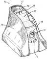
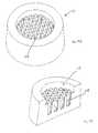
- FIG. 1is a perspective view of the main body of a scope cleaning device.
- FIG. 2is a cross-sectional view of the scope cleaning device of FIG. 1 with a stand added.
- FIG. 3is a perspective view of the main body and stand of a scope cleaning device.
- FIG. 4is a perspective view of the stand of a scope cleaning device.
- FIG. 5is a perspective view of the main body and stand separated to highlight the ability to cradle a scope when arranged in the horizontal position.
- FIG. 6is a perspective view of an alternate embodiment of the scope cleaning device
- FIG. 7is a rear perspective view of the scope cleaning device of FIG. 6 .
- FIG. 8is an exploded view of the scope cleaning device of FIG. 6 .
- FIG. 9is a cross-sectional view of the scope cleaning device of FIG. 6 .
- FIG. 10is a detailed cross sectional view of a portion of the scope cleaning device of FIG. 6 .
- FIG. 11is a detailed cross sectional view of an alternate embodiment of the scope cleaning device of FIG. 6 .
- FIG. 12is a perspective view of the portion of the scope cleaning device of FIG. 6 containing the white balance reference material.
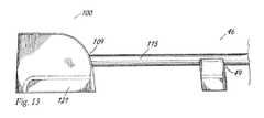
- FIG. 13is a side elevational view of the scope cleaning device and a stand for supporting a scope.
- FIG. 14Ais a perspective view of an alternate embodiment of the cleaning material.
- FIG. 14Bis a cross-sectional perspective view of the embodiment shown in FIG. 14A .
- FIG. 15Ais a perspective view of another alternate embodiment of the cleaning material.
- FIG. 15Bis a cross-sectional perspective view of the embodiment shown in FIG. 15A .
- FIG. 16is a schematic diagram of the electrical circuit of the present invention.
- the scope cleaning device 10has a first opening 13 for receiving a generally vertically oriented scope and a second opening 16 for receiving a generally horizontally oriented scope.
- a plurality of illumination devicessuch as light emitting diodes 11 may be disposed around the openings 13 , 16 to facilitate the insertion of the surgical scopes in darker environments.
- the openings 13 , 16may be sealed by a frangible disc 17 , 18 made of an elastomeric material or the like. The seals are provided to seal the cleaning solution in the device prior to use.
- the scope cleaning devicehas a housing 19 that is closed and sealed to protect the internal compartments from exposure to outside elements.
- a microfiber wipe 22may be mounted to the exterior of the housing 19 such that a scope 115 ( FIG. 13 ) may be brought into contact with the wipe 22 to remove debris.
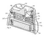
- the device 10uses separate compartments to clean, warm and white balance a scope.
- a cavity 28 formed in the body of the housingreceives the scope 115 .
- a cleaning material 31is positioned at the bottom of the cavity 28 .
- the cleaning material 31may comprise a sponge or other soft, porous material for receiving and holding a cleaning solution 34 ( FIG. 10 ).
- the cleaning material 31soaks up the liquid and transfers heat to the scope 115 .
- the cleaning solutionmay be any biocompatible, sterile solution capable of being retained by the cleaning material 31 in the cavity 28 .
- the end of the scope 115is cleaned and warmed by contact with the cleaning material which may be partially immersed in the heated, cleaning solution 34 .
- a resistance type electrical heating circuit 30may be located underneath the cleaning material 31 .
- the heating circuit 30may include resistors on a printed circuit board 35 .
- the electrical circuit 30 for generating heat through the resistorsmay be powered by a battery 36 , battery pack, DC or AC power from an outlet.
- a battery compartment 38may be located underneath the circuit board 35 .
- second opening 16extends to a second horizontally disposed cavity 37 for receiving the scope 115 .
- the horizontally disposed cavity 37may contain a pair of sponges or a cleaning material 39 that is split to provide a channel for sliding the scope 115 through the cleaning material 39 .
- the two spongesare configured to accept and to warm scopes 115 of all sizes.
- a V-shaped white reference material 40is disposed at the end of the cavity 37 .
- the white balance reference material 40is constructed of a non-porous material such as a silicone.
- the white balance reference material 40does not hold any liquid or cleaning solution and is arranged to provide a white balance for providing a reference color for optimizing the camera.
- the white balance reference material 40is V-shaped so that scopes 115 of different diameters may be inserted through the cleaning material 39 and into contact with the white balance reference material 40 .
- a stand 46is shown in a position abutting with the housing 19 .
- the stand 46may also be disposed in spaced apart relation as shown in FIGS. 5 and 13 .
- the stand 46provides support for the scope 115 while it is inserted into the horizontally oriented cavity 37 .
- the stand 46may be provided with an opening 49 bordered by a curved upper surface 50 .
- the stand 46may have a flat base 52 and a pair of side walls 55 , 58 .
- the side walls 55 , 58extend to a top surface 61 a , 61 b that borders the opening 49 .
- the opening 49is sized to be larger than the outside diameter of the scope 115 such that the scope 115 may slide into and out of the opening 49 .
- the stand 46is disposed in spaced apart relation relative to the scope cleaning device 10 .
- the stand 46is disposed such that a scope 115 deployed in opening 16 will align with the opening 49 at the top of the stand 46 .
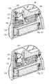
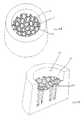
- scope cleaning device 100is an alternate embodiment of scope cleaning device 10 .
- the device 100includes a housing 103 having a first opening 106 and a second opening 109 .
- a microfiber wipe 112may be disposed at the top of the housing 103 for manually wiping off a scope 115 .
- the housing 103may extend outward in both directions toward the base 118 of the device 110 . The wider portion of the housing 103 at the base 118 provides for greater stability when inserting the scope 115 .
- the device 100includes the microfiber wipe 112 at the top of the housing 103 .
- the housing 103is a formed from a hollow shell 121 that forms internal cavities and protects the interior components from exposure to external elements.
- the first opening 106may extend to a first chamber 124 ( FIG. 9 ) formed in a subhousing 127 .
- the subhousing 127has an opening 130 at the top that provides a seal.
- the exterior of subhousing 127may be formed on the right hand side with a V-shaped section that receives a white balance reference material 133 .
- the subhousing 127may be received on top of subhousing 136 that forms a base for supporting subhousing 127 , printed circuit board 139 , a first cleaning material 142 such as a sponge or the like disposed in subhousing 127 , and a second cleaning material 145 that is disposed in a horizontal chamber 148 ( FIG. 9 ).
- the second cleaning material 145may comprise a pair of sponges 145 a and 145 b (best shown in FIG. 12 ) or cloths or may comprise a split cleaning material having a channel formed therein for receiving the scope 115 .
- the subhousing 136provides an enclosure for a battery compartment 151 .
- the batteries 154may be arranged on a base 155 in a circuit for providing heat through electrical resistance in the printed circuit board 139 .
- the circuit board 139may be designed to have multiple and separate heater sections built in to the circuit.
- the circuitmay be rigid or flexible.
- the deviceis provided with an electronic control circuit to maintain printed circuit board (PCB) temperature of the heating circuit for warming the cleaning fluid.
- the heateris designed with enough resistance to allow heating, but to still protect against thermal runaway in a fault condition.
- the systemmay be provided with light emitting diodes or LED's to illuminate the separate ports for cleaning and white balance.
- the systemmay be provided with an on-off switch or there may simply be an insulating pull tab 157 that can be removed to complete the circuit. As shown in FIG.
- the cleaning fluid 34( FIG. 10 ) is warmed by the printed circuit board 139 and the warmed cleaning fluid 34 may be absorbed into the first and second cleaning materials 142 and 145 . Accordingly, when a scope 115 is inserted into the first opening 106 , the scope 115 can be pushed into contact with the cleaning material 142 to clean the end of the scope and to warm it for reinsertion into the cavity of the patient. When a scope 115 is inserted into the second opening 109 , the scope 115 slides between the two sides 145 a and 145 b of the second cleaning material 145 such that a cleaning solution wipes off the scope 115 as it slides past. The scope 115 extends to the V-shaped white balance reference material 133 where it may be inserted until it makes contact. Because of the V-shape, the white balance reference material 133 is capable of accommodating scopes 115 having many different diameters.
- the cleaning fluid 34may be contained in one or both of the chambers located above the printed circuit board 139 .
- the fluid levelmay extend above the first cleaning material 142 and, if present in the second chamber 148 , may extend for a majority of the height of the second cleaning material 145 .
- the white balance reference material 133is located above the fluid level as fluid on the white balance reference material 133 would disrupt the white balancing and would not produce good results for the imaging.
- the first and second chamber 124 , 148may be separate and the second chamber 148 may not contain fluid.
- the white balance reference material 133is preferably a non-porous silicone material that does not absorb or retain any cleaning fluid solution. Turning to FIG.
- the first cleaning material 142may comprise a sponge or it may comprise a cross-hatched silicone cleaning material 170 .
- the cross-hatched silicone material 170may provide superior cleaning of the surface of the scope in comparison to a sponge.
- the use of a silicone or similar flexible material in a cross hatched patternprovides additional surface area for the cleaning material and provides improved cleaning of the lens.
- the second opening 109extends to a chamber having a pair of sponges 145 a and 145 b with a longitudinal channel 146 disposed between the sponges.
- a white balance reference material 133is disposed in spaced apart relation from the end of the sponges.
- the scope 115may extend through the channel 146 between the sponges and may extending into contact with the white balance reference material 133 for white balancing according to the specifications for the camera.
- the stand 46may be disposed in spaced apart relation to the scope cleaning device 100 so that the scope 115 may be supported in a substantially horizontal configuration.
- Cleaning material 231includes a plurality of upstanding finger-like projections 234 .
- the finger-like projections 234provide a surface for cleaning a surgical scope inside the cavity 28 .
- a honey-comb like structure 251includes a plurality of openings 254 divided by connecting walls 257 .
- FIG. 16is a schematic diagram of one embodiment of the electrical circuit.
- the circuit 299includes a power source such as a battery 300 ; a heating element 303 ; a thermistor 306 ; a plurality of LED's 309 , 312 ; and a plurality of resistors 315 , 318 , 321 , and 324 .
- the circuit componentsmay be integrated into a single printed circuit board. With the heater and components integrated into one board, any heat generated by the power transistor 327 which controls the power going to the heating element 303 is also used to warm the fluid. Also, with the temperature sensor (thermistor 306 ) integrated into the same board that includes the heating element, there is little to no latency in sensing temperature changes. In the case of a battery powered circuit, the circuit may electronically adjust for the varying voltage over the battery life with pulse width modulation. This feature may be used to maintain the required temperature setpoint of the device over the expected range of four to six hours.
Landscapes
- Health & Medical Sciences (AREA)
- Life Sciences & Earth Sciences (AREA)
- Surgery (AREA)
- General Health & Medical Sciences (AREA)
- Public Health (AREA)
- Veterinary Medicine (AREA)
- Pathology (AREA)
- Nuclear Medicine, Radiotherapy & Molecular Imaging (AREA)
- Animal Behavior & Ethology (AREA)
- Engineering & Computer Science (AREA)
- Biomedical Technology (AREA)
- Heart & Thoracic Surgery (AREA)
- Medical Informatics (AREA)
- Molecular Biology (AREA)
- Biophysics (AREA)
- Physics & Mathematics (AREA)
- Radiology & Medical Imaging (AREA)
- Optics & Photonics (AREA)
- Oral & Maxillofacial Surgery (AREA)
- Endoscopes (AREA)
Abstract
Description
Claims (25)
Priority Applications (1)
| Application Number | Priority Date | Filing Date | Title |
|---|---|---|---|
| US14/779,986US9775502B2 (en) | 2014-05-06 | 2015-05-06 | Laparascope and endoscope cleaning and defogging device |
Applications Claiming Priority (3)
| Application Number | Priority Date | Filing Date | Title |
|---|---|---|---|
| US201461989220P | 2014-05-06 | 2014-05-06 | |
| PCT/US2015/029479WO2015171771A1 (en) | 2014-05-06 | 2015-05-06 | Laparoscope and endoscope cleaning and defogging device |
| US14/779,986US9775502B2 (en) | 2014-05-06 | 2015-05-06 | Laparascope and endoscope cleaning and defogging device |
Publications (2)
| Publication Number | Publication Date |
|---|---|
| US20160135673A1 US20160135673A1 (en) | 2016-05-19 |
| US9775502B2true US9775502B2 (en) | 2017-10-03 |
Family
ID=54392957
Family Applications (1)
| Application Number | Title | Priority Date | Filing Date |
|---|---|---|---|
| US14/779,986Active2035-11-11US9775502B2 (en) | 2014-05-06 | 2015-05-06 | Laparascope and endoscope cleaning and defogging device |
Country Status (7)
| Country | Link |
|---|---|
| US (1) | US9775502B2 (en) |
| EP (1) | EP3139812B1 (en) |
| AU (1) | AU2015256076B2 (en) |
| CA (1) | CA2948182C (en) |
| DK (1) | DK3139812T3 (en) |
| ES (1) | ES2718558T3 (en) |
| WO (1) | WO2015171771A1 (en) |
Cited By (2)
| Publication number | Priority date | Publication date | Assignee | Title |
|---|---|---|---|---|
| US20190059713A1 (en)* | 2017-08-29 | 2019-02-28 | Dare Surgical Design LLC | Medical scope cleaning device |
| US11154187B2 (en) | 2019-05-29 | 2021-10-26 | Peter H. Kwon | Apparatus and method for in vivo cleaning of an optical lens of a surgical visualization device |
Families Citing this family (15)
| Publication number | Priority date | Publication date | Assignee | Title |
|---|---|---|---|---|
| US8402596B2 (en)* | 2010-06-17 | 2013-03-26 | Inventive Solutions, Llc | Directional atomizer system for cleaning chandeliers |
| US10912699B2 (en) | 2012-01-10 | 2021-02-09 | Alessio Pigazzi | Method of securing a patient onto an operating table when the patient is in a position such as the trendelenburg position and apparatus therefor including a kit |
| USD765840S1 (en)* | 2014-12-03 | 2016-09-06 | Buffalo Filter Llc | Laparoscope and endoscope cleaning and defogging device |
| US10080488B2 (en) | 2014-12-12 | 2018-09-25 | Medix3d LLC | Cleaning device for cleaning a scope, laparoscope or microscope used in surgery or other medical procedures and a method of using the device during surgical or other medical procedures |
| US10426327B2 (en) | 2015-11-02 | 2019-10-01 | Buffalo Filter Llc | Fluid filtration, cleaning, and defogging device |
| US10263376B1 (en)* | 2016-04-25 | 2019-04-16 | Alton B. Brown | Connector cleaner |
| CN105725956A (en)* | 2016-05-14 | 2016-07-06 | 黄昌明 | Insulation jug for lens of laparoscope |
| USD868997S1 (en) | 2017-09-15 | 2019-12-03 | Adventist Health System/Sunbelt, Inc. | Scope warmer apparatus |
| US20190159665A1 (en)* | 2017-11-28 | 2019-05-30 | Covidien Lp | Devices for cleaning medical videoscopes |
| CA3090710A1 (en)* | 2019-08-21 | 2021-02-21 | BATRIK Medical Manufacturing Inc. | Dispensing device |
| CN111419159B (en)* | 2020-04-03 | 2024-12-27 | 四川省肿瘤医院 | Laparoscopic lens cleaning device |
| CN112515617A (en)* | 2020-11-24 | 2021-03-19 | 上海圭革智能传感技术有限公司 | Endoscope defogging device and endoscope system |
| US20230087044A1 (en)* | 2021-09-22 | 2023-03-23 | Titan Medical Inc. | Systems, methods, and apparatuses for cleaning a camera during a medical procedure |
| US12201274B1 (en) | 2023-07-09 | 2025-01-21 | Scopix Ltd. | Surgical port add-on and adaptor for a surgical port |
| KR102795976B1 (en)* | 2024-02-26 | 2025-04-16 | 주식회사 베젤 | Medical scope cleaning equipment |
Citations (58)
| Publication number | Priority date | Publication date | Assignee | Title |
|---|---|---|---|---|
| US3980078A (en) | 1974-07-23 | 1976-09-14 | Fuji Photo Optical Co., Ltd. | Endoscope with cleaning device |
| US4279246A (en) | 1978-06-19 | 1981-07-21 | Machida Endoscope Co., Ltd. | Device for preventing clouding of an observing window |
| US4805598A (en) | 1986-09-26 | 1989-02-21 | Olympus Optical Co., Ltd. | Endoscope having optical elements that are resistant to condensation |
| US5225001A (en) | 1990-09-19 | 1993-07-06 | Healthtek | Single channel scope cleaning method and apparatus |
| US5237984A (en) | 1991-06-24 | 1993-08-24 | Xomed-Treace Inc. | Sheath for endoscope |
| US5274874A (en) | 1992-03-13 | 1994-01-04 | Merocel Corporation | Endoscope cleaning and defogging apparatus |
| US5313934A (en) | 1992-09-10 | 1994-05-24 | Deumed Group Inc. | Lens cleaning means for invasive viewing medical instruments |
| US5339800A (en) | 1992-09-10 | 1994-08-23 | Devmed Group Inc. | Lens cleaning means for invasive viewing medical instruments with anti-contamination means |
| US5347988A (en) | 1992-05-13 | 1994-09-20 | Linvatec Corporation | Endoscope coupler with liquid interface |
| US5351675A (en) | 1992-08-14 | 1994-10-04 | The Kendall Company | Method and apparatus for preheating an optical instrument prior to use thereof in a medical procedure |
| US5386817A (en) | 1991-06-10 | 1995-02-07 | Endomedical Technologies, Inc. | Endoscope sheath and valve system |
| US5392766A (en) | 1993-10-06 | 1995-02-28 | Innerdyne Medical, Inc. | System and method for cleaning viewing scope lenses |
| US5400767A (en) | 1991-05-14 | 1995-03-28 | Murdoch; Mervyn J. | Laparoscopic telescope lens cleaner and protector |
| US5448990A (en) | 1994-02-15 | 1995-09-12 | Very Inventive Physicians, Inc. | Endoscope viewing cannula and surgical techniques |
| US5458633A (en) | 1994-05-24 | 1995-10-17 | Bailey; Robert W. | Irrigating laparoscopic cannula or trocar |
| US5464008A (en) | 1994-04-14 | 1995-11-07 | Kim; John H. | Laparoscope defogging |
| US5518502A (en) | 1994-06-08 | 1996-05-21 | The United States Surgical Corporation | Compositions, methods and apparatus for inhibiting fogging of endoscope lenses |
| US5533496A (en) | 1994-02-15 | 1996-07-09 | Very Inventive Physicians, Inc. | Endoscopic technique particularly suited for exploratory surgery |
| US5549543A (en) | 1995-06-01 | 1996-08-27 | Kim; Il G. | Laparoscopic defogging apparatus |
| US5605532A (en) | 1995-10-20 | 1997-02-25 | Vista Medical Technologies, Inc. | Fog-free endoscope |
| US5647840A (en) | 1994-09-14 | 1997-07-15 | Circon Corporation | Endoscope having a distally heated distal lens |
| US5651757A (en) | 1996-02-15 | 1997-07-29 | Meckstroth; Clyde S. | Endoscope warmer |
| US5894369A (en) | 1996-11-15 | 1999-04-13 | Fuji Photo Optical Co., Ltd. | Lens device with anti-fogging |
| US5910106A (en) | 1998-05-15 | 1999-06-08 | Fieldtech Avionics And Instruments, Inc. | Method and apparatus for heating a surgical instrument |
| US6017333A (en) | 1995-04-13 | 2000-01-25 | Bailey; Robert W. | Irrigating laparoscopic cannula |
| US6231596B1 (en) | 1998-07-27 | 2001-05-15 | Heat Max, Inc. | Surgical instrument warming device |
| US6234635B1 (en) | 1998-07-30 | 2001-05-22 | Michael R. Seitzinger | Method for preventing laparoscope fogging |
| US20020022762A1 (en) | 2000-02-18 | 2002-02-21 | Richard Beane | Devices and methods for warming and cleaning lenses of optical surgical instruments |
| US6712479B1 (en) | 1998-07-30 | 2004-03-30 | Innovative Surgical Technology, Inc. | Method for preventing laparoscope fogging |
| WO2004080294A1 (en) | 2003-03-11 | 2004-09-23 | Takeshi Ohdaira | Laparoscope fogging prevention device, member for preventing fogging of laparoscope, light transmission member for preventing fogging of laparoscope, and method of preventing fogging of laparoscope |
| US7080641B2 (en) | 2004-04-16 | 2006-07-25 | Ricardo Alexander Gomez | Method and apparatus for heating sterile solutions during medical procedures |
| US7291308B2 (en) | 2004-08-27 | 2007-11-06 | Ethicon, Inc. | Endoscope immersion tray |
| US7311660B2 (en) | 2004-04-16 | 2007-12-25 | Ricardo Alexander Gomez | Method and apparatus for heating and applying warm antifog solution to endoscopes as well as a distal lens protector |
| US20080194915A1 (en) | 2004-04-05 | 2008-08-14 | Michael Joseph Blackhurst | Scope Warming Device |
| US20090112057A1 (en) | 2007-10-26 | 2009-04-30 | Patrick Kammer | Anti-fogging and cleaning apparatus for medical scopes |
| US7537563B2 (en) | 2003-04-17 | 2009-05-26 | John Temple | Heater for surgical viewing instruments |
| US20090247832A1 (en) | 2003-04-17 | 2009-10-01 | John Temple | Heater for surgical viewing instruments |
| US7648023B2 (en) | 2006-04-27 | 2010-01-19 | Cygnus Medical Llc | Endoscope pre-clean kit |
| US7671302B1 (en) | 2004-03-23 | 2010-03-02 | O. R. Solutions, Inc. | Thermal treatment system instrument rack and method of selectively thermally treating medical instrument portions |
| US7727262B2 (en) | 2000-06-23 | 2010-06-01 | Warsaw Orthopedic, Inc. | Formed in place fixation system with thermal acceleration |
| US7803109B2 (en) | 2004-04-16 | 2010-09-28 | Ricardo Alexander Gomez | Method and apparatus for protecting the distal lens of endoscopes |
| US20100270295A1 (en) | 2009-04-27 | 2010-10-28 | Ching-Chuan Wang | Scopes heating device |
| US8001984B2 (en) | 2006-06-06 | 2011-08-23 | Sasaki Larry S | Laparoscopic lens cleaner |
| US8047215B1 (en) | 2006-06-06 | 2011-11-01 | Larry Sasaki | Laparoscopic lens cleaner |
| US8153937B2 (en) | 2004-03-23 | 2012-04-10 | Ecolab Inc. | Thermal treatment system instrument rack and method of selectively thermally treating medical instrument portions |
| US8152717B2 (en) | 2006-01-30 | 2012-04-10 | Ricardo Alexander Gomez | Device for white balancing and appying an anti-fog agent to medical videoscopes prior to medical procedures |
| US8185997B2 (en) | 2007-11-05 | 2012-05-29 | New Wave Surgical Corporation | Method and apparatus for cleaning the interior cannula of laparoscopic and endoscopic access devices |
| US20120187104A1 (en) | 2010-09-02 | 2012-07-26 | Ecolab Usa Inc. | Selective Thermal Treatment of Medical Instrument Portions With Thermal Treatment System Instrument Holder |
| US20120197084A1 (en) | 2007-06-19 | 2012-08-02 | Minimally Invasive Devices, Llc | Systems and methods for optimizing and maintaining visualization of a surgical field during the use of surgical scopes |
| US20120238818A1 (en) | 2011-02-09 | 2012-09-20 | O'prey Cormac | Covering Apparatus For An Endoscope Lens |
| WO2012169433A1 (en) | 2011-06-08 | 2012-12-13 | オリンパス株式会社 | Clouding prevention system for endoscope |
| WO2013012790A2 (en) | 2011-07-15 | 2013-01-24 | The Johns Hopkins University | Multi-purpose trocar with lens cleaner |
| US8376936B2 (en) | 2010-05-28 | 2013-02-19 | Top-Bound Enterprise Co., Ltd. | Videoscope preheater |
| US8400499B2 (en) | 2007-11-21 | 2013-03-19 | Panasonic Corporation | Endoscope device, camera device for endoscope, and defogging method |
| US8480699B2 (en) | 2006-09-01 | 2013-07-09 | II Glenn M. Ihde | Fluid absorbent surgical device for trocars |
| US20130186428A1 (en) | 2009-03-16 | 2013-07-25 | Midbrook, Inc. | Method and Apparatus for Cleaning of Laparoscopic Surgical Instruments |
| US8550988B2 (en) | 2008-04-21 | 2013-10-08 | Covidien Lp | Endoscopic cleaner |
| US20150080660A1 (en) | 2013-09-18 | 2015-03-19 | New Wave Surgical Corp. | Laparoscopic Visualization System |
Family Cites Families (3)
| Publication number | Priority date | Publication date | Assignee | Title |
|---|---|---|---|---|
| US20040199052A1 (en)* | 2003-04-01 | 2004-10-07 | Scimed Life Systems, Inc. | Endoscopic imaging system |
| US8267896B2 (en)* | 2009-12-18 | 2012-09-18 | Tyco Healthcare Group Lp | Surgical instrument cleaning arrangement |
| JP5412601B2 (en)* | 2011-12-07 | 2014-02-12 | オリンパスメディカルシステムズ株式会社 | Electronic endoscope |
- 2015
- 2015-05-06EPEP15789152.4Apatent/EP3139812B1/enactiveActive
- 2015-05-06USUS14/779,986patent/US9775502B2/enactiveActive
- 2015-05-06ESES15789152Tpatent/ES2718558T3/enactiveActive
- 2015-05-06CACA2948182Apatent/CA2948182C/enactiveActive
- 2015-05-06DKDK15789152.4Tpatent/DK3139812T3/enactive
- 2015-05-06WOPCT/US2015/029479patent/WO2015171771A1/enactiveApplication Filing
- 2015-05-06AUAU2015256076Apatent/AU2015256076B2/enactiveActive
Patent Citations (61)
| Publication number | Priority date | Publication date | Assignee | Title |
|---|---|---|---|---|
| US3980078A (en) | 1974-07-23 | 1976-09-14 | Fuji Photo Optical Co., Ltd. | Endoscope with cleaning device |
| US4279246A (en) | 1978-06-19 | 1981-07-21 | Machida Endoscope Co., Ltd. | Device for preventing clouding of an observing window |
| US4805598A (en) | 1986-09-26 | 1989-02-21 | Olympus Optical Co., Ltd. | Endoscope having optical elements that are resistant to condensation |
| US5225001A (en) | 1990-09-19 | 1993-07-06 | Healthtek | Single channel scope cleaning method and apparatus |
| US5400767A (en) | 1991-05-14 | 1995-03-28 | Murdoch; Mervyn J. | Laparoscopic telescope lens cleaner and protector |
| US5386817A (en) | 1991-06-10 | 1995-02-07 | Endomedical Technologies, Inc. | Endoscope sheath and valve system |
| US5237984A (en) | 1991-06-24 | 1993-08-24 | Xomed-Treace Inc. | Sheath for endoscope |
| US5413092A (en) | 1991-06-24 | 1995-05-09 | Xomed-Treace, Inc. | Sheath for endoscope |
| US5274874A (en) | 1992-03-13 | 1994-01-04 | Merocel Corporation | Endoscope cleaning and defogging apparatus |
| US5382297A (en) | 1992-03-13 | 1995-01-17 | Merocel Corporation | Endoscope cleaning and defogging apparatus |
| US5347988A (en) | 1992-05-13 | 1994-09-20 | Linvatec Corporation | Endoscope coupler with liquid interface |
| US5351675A (en) | 1992-08-14 | 1994-10-04 | The Kendall Company | Method and apparatus for preheating an optical instrument prior to use thereof in a medical procedure |
| US5339800A (en) | 1992-09-10 | 1994-08-23 | Devmed Group Inc. | Lens cleaning means for invasive viewing medical instruments with anti-contamination means |
| US5313934A (en) | 1992-09-10 | 1994-05-24 | Deumed Group Inc. | Lens cleaning means for invasive viewing medical instruments |
| US5392766A (en) | 1993-10-06 | 1995-02-28 | Innerdyne Medical, Inc. | System and method for cleaning viewing scope lenses |
| US5448990A (en) | 1994-02-15 | 1995-09-12 | Very Inventive Physicians, Inc. | Endoscope viewing cannula and surgical techniques |
| US5533496A (en) | 1994-02-15 | 1996-07-09 | Very Inventive Physicians, Inc. | Endoscopic technique particularly suited for exploratory surgery |
| US5464008A (en) | 1994-04-14 | 1995-11-07 | Kim; John H. | Laparoscope defogging |
| US5458633A (en) | 1994-05-24 | 1995-10-17 | Bailey; Robert W. | Irrigating laparoscopic cannula or trocar |
| US5518502A (en) | 1994-06-08 | 1996-05-21 | The United States Surgical Corporation | Compositions, methods and apparatus for inhibiting fogging of endoscope lenses |
| US5647840A (en) | 1994-09-14 | 1997-07-15 | Circon Corporation | Endoscope having a distally heated distal lens |
| US6017333A (en) | 1995-04-13 | 2000-01-25 | Bailey; Robert W. | Irrigating laparoscopic cannula |
| US5549543A (en) | 1995-06-01 | 1996-08-27 | Kim; Il G. | Laparoscopic defogging apparatus |
| US5605532A (en) | 1995-10-20 | 1997-02-25 | Vista Medical Technologies, Inc. | Fog-free endoscope |
| US5651757A (en) | 1996-02-15 | 1997-07-29 | Meckstroth; Clyde S. | Endoscope warmer |
| US5894369A (en) | 1996-11-15 | 1999-04-13 | Fuji Photo Optical Co., Ltd. | Lens device with anti-fogging |
| US5910106A (en) | 1998-05-15 | 1999-06-08 | Fieldtech Avionics And Instruments, Inc. | Method and apparatus for heating a surgical instrument |
| US6231596B1 (en) | 1998-07-27 | 2001-05-15 | Heat Max, Inc. | Surgical instrument warming device |
| US6234635B1 (en) | 1998-07-30 | 2001-05-22 | Michael R. Seitzinger | Method for preventing laparoscope fogging |
| US6712479B1 (en) | 1998-07-30 | 2004-03-30 | Innovative Surgical Technology, Inc. | Method for preventing laparoscope fogging |
| US20020022762A1 (en) | 2000-02-18 | 2002-02-21 | Richard Beane | Devices and methods for warming and cleaning lenses of optical surgical instruments |
| US7727262B2 (en) | 2000-06-23 | 2010-06-01 | Warsaw Orthopedic, Inc. | Formed in place fixation system with thermal acceleration |
| WO2004080294A1 (en) | 2003-03-11 | 2004-09-23 | Takeshi Ohdaira | Laparoscope fogging prevention device, member for preventing fogging of laparoscope, light transmission member for preventing fogging of laparoscope, and method of preventing fogging of laparoscope |
| US7537563B2 (en) | 2003-04-17 | 2009-05-26 | John Temple | Heater for surgical viewing instruments |
| US20090247832A1 (en) | 2003-04-17 | 2009-10-01 | John Temple | Heater for surgical viewing instruments |
| US7671302B1 (en) | 2004-03-23 | 2010-03-02 | O. R. Solutions, Inc. | Thermal treatment system instrument rack and method of selectively thermally treating medical instrument portions |
| US8153937B2 (en) | 2004-03-23 | 2012-04-10 | Ecolab Inc. | Thermal treatment system instrument rack and method of selectively thermally treating medical instrument portions |
| US8148667B2 (en) | 2004-03-23 | 2012-04-03 | Ecolab Inc. | Thermal treatment system instrument rack and method of selectively thermally treating medical instrument portions |
| US20080194915A1 (en) | 2004-04-05 | 2008-08-14 | Michael Joseph Blackhurst | Scope Warming Device |
| US7311660B2 (en) | 2004-04-16 | 2007-12-25 | Ricardo Alexander Gomez | Method and apparatus for heating and applying warm antifog solution to endoscopes as well as a distal lens protector |
| US7080641B2 (en) | 2004-04-16 | 2006-07-25 | Ricardo Alexander Gomez | Method and apparatus for heating sterile solutions during medical procedures |
| US7803109B2 (en) | 2004-04-16 | 2010-09-28 | Ricardo Alexander Gomez | Method and apparatus for protecting the distal lens of endoscopes |
| US7291308B2 (en) | 2004-08-27 | 2007-11-06 | Ethicon, Inc. | Endoscope immersion tray |
| US8152717B2 (en) | 2006-01-30 | 2012-04-10 | Ricardo Alexander Gomez | Device for white balancing and appying an anti-fog agent to medical videoscopes prior to medical procedures |
| US7648023B2 (en) | 2006-04-27 | 2010-01-19 | Cygnus Medical Llc | Endoscope pre-clean kit |
| US8047215B1 (en) | 2006-06-06 | 2011-11-01 | Larry Sasaki | Laparoscopic lens cleaner |
| US8001984B2 (en) | 2006-06-06 | 2011-08-23 | Sasaki Larry S | Laparoscopic lens cleaner |
| US8480699B2 (en) | 2006-09-01 | 2013-07-09 | II Glenn M. Ihde | Fluid absorbent surgical device for trocars |
| US20120197084A1 (en) | 2007-06-19 | 2012-08-02 | Minimally Invasive Devices, Llc | Systems and methods for optimizing and maintaining visualization of a surgical field during the use of surgical scopes |
| US20090112057A1 (en) | 2007-10-26 | 2009-04-30 | Patrick Kammer | Anti-fogging and cleaning apparatus for medical scopes |
| US8185997B2 (en) | 2007-11-05 | 2012-05-29 | New Wave Surgical Corporation | Method and apparatus for cleaning the interior cannula of laparoscopic and endoscopic access devices |
| US8400499B2 (en) | 2007-11-21 | 2013-03-19 | Panasonic Corporation | Endoscope device, camera device for endoscope, and defogging method |
| US8550988B2 (en) | 2008-04-21 | 2013-10-08 | Covidien Lp | Endoscopic cleaner |
| US20130186428A1 (en) | 2009-03-16 | 2013-07-25 | Midbrook, Inc. | Method and Apparatus for Cleaning of Laparoscopic Surgical Instruments |
| US20100270295A1 (en) | 2009-04-27 | 2010-10-28 | Ching-Chuan Wang | Scopes heating device |
| US8376936B2 (en) | 2010-05-28 | 2013-02-19 | Top-Bound Enterprise Co., Ltd. | Videoscope preheater |
| US20120187104A1 (en) | 2010-09-02 | 2012-07-26 | Ecolab Usa Inc. | Selective Thermal Treatment of Medical Instrument Portions With Thermal Treatment System Instrument Holder |
| US20120238818A1 (en) | 2011-02-09 | 2012-09-20 | O'prey Cormac | Covering Apparatus For An Endoscope Lens |
| WO2012169433A1 (en) | 2011-06-08 | 2012-12-13 | オリンパス株式会社 | Clouding prevention system for endoscope |
| WO2013012790A2 (en) | 2011-07-15 | 2013-01-24 | The Johns Hopkins University | Multi-purpose trocar with lens cleaner |
| US20150080660A1 (en) | 2013-09-18 | 2015-03-19 | New Wave Surgical Corp. | Laparoscopic Visualization System |
Cited By (2)
| Publication number | Priority date | Publication date | Assignee | Title |
|---|---|---|---|---|
| US20190059713A1 (en)* | 2017-08-29 | 2019-02-28 | Dare Surgical Design LLC | Medical scope cleaning device |
| US11154187B2 (en) | 2019-05-29 | 2021-10-26 | Peter H. Kwon | Apparatus and method for in vivo cleaning of an optical lens of a surgical visualization device |
Also Published As
| Publication number | Publication date |
|---|---|
| ES2718558T3 (en) | 2019-07-02 |
| CA2948182A1 (en) | 2015-11-12 |
| CA2948182C (en) | 2019-02-26 |
| WO2015171771A1 (en) | 2015-11-12 |
| EP3139812B1 (en) | 2019-01-09 |
| AU2015256076B2 (en) | 2019-05-16 |
| DK3139812T3 (en) | 2019-04-23 |
| EP3139812A1 (en) | 2017-03-15 |
| EP3139812A4 (en) | 2018-01-10 |
| AU2015256076A1 (en) | 2016-12-15 |
| US20160135673A1 (en) | 2016-05-19 |
Similar Documents
| Publication | Publication Date | Title |
|---|---|---|
| US9775502B2 (en) | Laparascope and endoscope cleaning and defogging device | |
| US12029394B2 (en) | Scope cleaning device configured to be removably connected to a surgical tool | |
| JP5628742B2 (en) | Scope heating device | |
| US20200288957A1 (en) | Laparoscopic visualization system | |
| CN101374452B (en) | Device for white balancing medical endoscope and applying anti-fog agent before medical procedure | |
| EP3244823B1 (en) | Device for accommodating surgical tool prior to and during medical procedures | |
| US11627872B2 (en) | Fluid filtration, cleaning, and defogging device | |
| US20190082945A1 (en) | Medical device warmer with removable insert | |
| WO2020176717A1 (en) | Scope cleaning device configured to be removably connected to a surgical tool | |
| US11723118B2 (en) | Disposable, battery powered surgical scope warmer |
Legal Events
| Date | Code | Title | Description |
|---|---|---|---|
| AS | Assignment | Owner name:BUFFALO FILTER LLC, NEW YORK Free format text:ASSIGNMENT OF ASSIGNORS INTEREST;ASSIGNORS:MILLER, MICHAEL J.;KELLNER, WILLIAM J.;LIZAUCKAS, ANTHONY L., III;AND OTHERS;REEL/FRAME:043472/0830 Effective date:20150630 | |
| STCF | Information on status: patent grant | Free format text:PATENTED CASE | |
| AS | Assignment | Owner name:JPMORGAN CHASE BANK, N.A., AS ADMINISTRATIVE AGENT Free format text:GRANT OF SECURITY INTEREST IN PATENT RIGHTS;ASSIGNOR:BUFFALO FILTER LLC;REEL/FRAME:048413/0947 Effective date:20190211 Owner name:JPMORGAN CHASE BANK, N.A., AS ADMINISTRATIVE AGENT, ILLINOIS Free format text:GRANT OF SECURITY INTEREST IN PATENT RIGHTS;ASSIGNOR:BUFFALO FILTER LLC;REEL/FRAME:048413/0947 Effective date:20190211 | |
| MAFP | Maintenance fee payment | Free format text:PAYMENT OF MAINTENANCE FEE, 4TH YEAR, LARGE ENTITY (ORIGINAL EVENT CODE: M1551); ENTITY STATUS OF PATENT OWNER: LARGE ENTITY Year of fee payment:4 | |
| MAFP | Maintenance fee payment | Free format text:PAYMENT OF MAINTENANCE FEE, 8TH YEAR, LARGE ENTITY (ORIGINAL EVENT CODE: M1552); ENTITY STATUS OF PATENT OWNER: LARGE ENTITY Year of fee payment:8 | |
| AS | Assignment | Owner name:JPMORGAN CHASE BANK, N.A., AS ADMINISTRATIVE AGENT, ILLINOIS Free format text:SECURITY INTEREST;ASSIGNORS:CONMED CORPORATION;BIOREZ, INC.;BUFFALO FILTER LLC;AND OTHERS;REEL/FRAME:072097/0762 Effective date:20250610 |