US9771070B2 - Method and system for controlling a host vehicle - Google Patents
Method and system for controlling a host vehicleDownload PDFInfo
- Publication number
- US9771070B2 US9771070B2US13/315,942US201113315942AUS9771070B2US 9771070 B2US9771070 B2US 9771070B2US 201113315942 AUS201113315942 AUS 201113315942AUS 9771070 B2US9771070 B2US 9771070B2
- Authority
- US
- United States
- Prior art keywords
- vehicle
- host vehicle
- target vehicle
- leading
- target
- Prior art date
- Legal status (The legal status is an assumption and is not a legal conclusion. Google has not performed a legal analysis and makes no representation as to the accuracy of the status listed.)
- Active, expires
Links
- 238000000034methodMethods0.000titleclaimsabstractdescription98
- 230000004044responseEffects0.000claimsabstractdescription62
- 230000001133accelerationEffects0.000claimsdescription17
- 230000003278mimic effectEffects0.000claimsdescription4
- 238000012790confirmationMethods0.000claimsdescription2
- 230000009471actionEffects0.000description7
- 230000009016anticipatory responseEffects0.000description7
- 230000008859changeEffects0.000description7
- 230000003044adaptive effectEffects0.000description4
- 238000004422calculation algorithmMethods0.000description4
- 238000004891communicationMethods0.000description4
- 238000000926separation methodMethods0.000description4
- 238000001514detection methodMethods0.000description3
- 238000013459approachMethods0.000description2
- 238000010276constructionMethods0.000description2
- 238000005516engineering processMethods0.000description2
- 238000012986modificationMethods0.000description2
- 230000004048modificationEffects0.000description2
- 238000012545processingMethods0.000description2
- 238000004458analytical methodMethods0.000description1
- 230000009118appropriate responseEffects0.000description1
- 230000003542behavioural effectEffects0.000description1
- 230000000903blocking effectEffects0.000description1
- 238000004364calculation methodMethods0.000description1
- 230000001419dependent effectEffects0.000description1
- 238000011161developmentMethods0.000description1
- 230000000694effectsEffects0.000description1
- 230000000116mitigating effectEffects0.000description1
- 238000002156mixingMethods0.000description1
- 239000000203mixtureSubstances0.000description1
- 238000012544monitoring processMethods0.000description1
- 230000003287optical effectEffects0.000description1
- 230000000737periodic effectEffects0.000description1
- 238000001556precipitationMethods0.000description1
- 238000002360preparation methodMethods0.000description1
- 230000008569processEffects0.000description1
- 230000000246remedial effectEffects0.000description1
- 238000013515scriptMethods0.000description1
Images


Classifications
- B—PERFORMING OPERATIONS; TRANSPORTING
- B60—VEHICLES IN GENERAL
- B60W—CONJOINT CONTROL OF VEHICLE SUB-UNITS OF DIFFERENT TYPE OR DIFFERENT FUNCTION; CONTROL SYSTEMS SPECIALLY ADAPTED FOR HYBRID VEHICLES; ROAD VEHICLE DRIVE CONTROL SYSTEMS FOR PURPOSES NOT RELATED TO THE CONTROL OF A PARTICULAR SUB-UNIT
- B60W30/00—Purposes of road vehicle drive control systems not related to the control of a particular sub-unit, e.g. of systems using conjoint control of vehicle sub-units
- B60W30/08—Active safety systems predicting or avoiding probable or impending collision or attempting to minimise its consequences
- B60W30/09—Taking automatic action to avoid collision, e.g. braking and steering
- B—PERFORMING OPERATIONS; TRANSPORTING
- B60—VEHICLES IN GENERAL
- B60W—CONJOINT CONTROL OF VEHICLE SUB-UNITS OF DIFFERENT TYPE OR DIFFERENT FUNCTION; CONTROL SYSTEMS SPECIALLY ADAPTED FOR HYBRID VEHICLES; ROAD VEHICLE DRIVE CONTROL SYSTEMS FOR PURPOSES NOT RELATED TO THE CONTROL OF A PARTICULAR SUB-UNIT
- B60W30/00—Purposes of road vehicle drive control systems not related to the control of a particular sub-unit, e.g. of systems using conjoint control of vehicle sub-units
- B60W30/08—Active safety systems predicting or avoiding probable or impending collision or attempting to minimise its consequences
- B60W30/095—Predicting travel path or likelihood of collision
- B60W30/0956—Predicting travel path or likelihood of collision the prediction being responsive to traffic or environmental parameters
- G—PHYSICS
- G05—CONTROLLING; REGULATING
- G05D—SYSTEMS FOR CONTROLLING OR REGULATING NON-ELECTRIC VARIABLES
- G05D1/00—Control of position, course, altitude or attitude of land, water, air or space vehicles, e.g. using automatic pilots
- G05D1/02—Control of position or course in two dimensions
- G05D1/021—Control of position or course in two dimensions specially adapted to land vehicles
- G05D1/0287—Control of position or course in two dimensions specially adapted to land vehicles involving a plurality of land vehicles, e.g. fleet or convoy travelling
- G05D1/0289—Control of position or course in two dimensions specially adapted to land vehicles involving a plurality of land vehicles, e.g. fleet or convoy travelling with means for avoiding collisions between vehicles
- B60W2550/302—
- B60W2550/306—
- B—PERFORMING OPERATIONS; TRANSPORTING
- B60—VEHICLES IN GENERAL
- B60W—CONJOINT CONTROL OF VEHICLE SUB-UNITS OF DIFFERENT TYPE OR DIFFERENT FUNCTION; CONTROL SYSTEMS SPECIALLY ADAPTED FOR HYBRID VEHICLES; ROAD VEHICLE DRIVE CONTROL SYSTEMS FOR PURPOSES NOT RELATED TO THE CONTROL OF A PARTICULAR SUB-UNIT
- B60W2554/00—Input parameters relating to objects
- B60W2554/40—Dynamic objects, e.g. animals, windblown objects
- B60W2554/404—Characteristics
- B60W2554/4041—Position
- B—PERFORMING OPERATIONS; TRANSPORTING
- B60—VEHICLES IN GENERAL
- B60W—CONJOINT CONTROL OF VEHICLE SUB-UNITS OF DIFFERENT TYPE OR DIFFERENT FUNCTION; CONTROL SYSTEMS SPECIALLY ADAPTED FOR HYBRID VEHICLES; ROAD VEHICLE DRIVE CONTROL SYSTEMS FOR PURPOSES NOT RELATED TO THE CONTROL OF A PARTICULAR SUB-UNIT
- B60W2554/00—Input parameters relating to objects
- B60W2554/80—Spatial relation or speed relative to objects
- B60W2554/804—Relative longitudinal speed
Definitions
- the present inventiongenerally relates to an active system for a vehicle and, more particularly, to an active vehicle system that monitors the behavior of one or more surrounding vehicles and alters, adjusts and/or controls operation of a host vehicle accordingly.
- the behavior of the surrounding vehiclescan sometimes act as a preview or warning for unseen hazards in the road. For example, if a leading vehicle suddenly swerves to avoid a large pothole or piece of debris in the road, then this can act as a warning to trailing vehicles that there is an unseen hazard for which preparations should be made, even though the hazard is not currently in the field of view of the trailing vehicles.
- Other examplesalso exist where the behavior of the surrounding vehicles—whether they be leading vehicles out in front of a host vehicle or side-by-side vehicles that surround a host vehicle—can be useful to predict and prepare for upcoming situations that cannot be directly sensed by the host vehicle. This may be particularly true when the host vehicle is operating in some type of autonomous or semi-autonomous driving mode, such as those employed by adaptive cruise control systems, lane-centering systems, automatic lane change systems, freeway-limited autonomous driving systems, etc.
- a method of controlling a host vehiclemay comprise the steps of: (a) receiving target vehicle readings from one or more target vehicle sensor(s) that monitor an area around the host vehicle; (b) using the target vehicle readings to determine if one or more target vehicle(s) are currently located in the area around the host vehicle; (c) if there are one or more target vehicle(s) currently located in the area around the host vehicle, then using the target vehicle readings to evaluate the behavior of the target vehicle(s); and (d) using the evaluated behavior of the one or more target vehicle(s) to avoid a hazard in the upcoming road segment without directly sensing the hazard with the one or more target vehicle sensor(s).
- a method of controlling a host vehiclemay comprise the steps of: (a) using target vehicle readings from one or more target vehicle sensor(s) to establish an observational area around the host vehicle; (b) analyzing the behavior of one or more target vehicle(s) within the observational area by identifying one or more vehicle maneuver(s); (c) categorizing the vehicle maneuver(s) as either a leading maneuver or a surrounding maneuver, a leading maneuver pertains to a maneuver by a target vehicle located in front of the host vehicle and a surrounding maneuver pertains to a maneuver by a target vehicle located on a side of the host vehicle; and (d) generating a preemptive response for the host vehicle based on the vehicle maneuver category, wherein the preemptive response causes an automatic acceleration, deceleration and/or steering of the host vehicle while the host vehicle is being driven in an autonomous or semi-autonomous mode.
- a method of controlling a host vehiclemay comprise the steps of: (a) using target vehicle readings from one or more target vehicle sensor(s) to establish an observational area around the host vehicle; (b) analyzing the behavior of a plurality of target vehicles within the observational area, at least some of the target vehicles are located on the sides of the host vehicle; (c) using the behavior of the plurality of target vehicles to develop a preemptive response for the host vehicle, wherein the preemptive response automatically controls the lateral and/or longitudinal position of the host vehicle and is designed to integrate the host vehicle into the plurality of target vehicles; and (d) sending command signals that are representative of the preemptive response to one or more control module(s) within the host vehicle so that the lateral and/or longitudinal position of the host vehicle can be automatically controlled.
- FIG. 1is a schematic view showing a host vehicle that includes an exemplary active vehicle system and is surrounded by several other vehicles;
- FIG. 2is a flowchart illustrating some of the steps of an exemplary method that may be used to control a host vehicle, such as the one shown in FIG. 1 ;
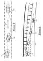
- FIGS. 3-7are schematic views demonstrating a number of different situations or scenarios that may warrant the use of the method shown in FIG. 2 .
- the active vehicle system described hereincan be installed on a host vehicle and can monitor the behavior of one or more surrounding vehicles in order to predict or anticipate an upcoming hazard in the road—whether it be an object in the road or a traffic event or something else—and to react to such a hazard, even in situations where the hazard cannot be directly sensed by the host vehicle.
- the active vehicle systemmonitors an area around the host vehicle while it is being driven and looks for the presence of one or more target vehicles. If target vehicles are detected, the active vehicle system may evaluate their behavior, classify their behavior into one of several categories, and assuming that their behavior suggests some type of upcoming hazard, the active vehicle system may develop an appropriate preemptive response. This response may include mimicking, copying and/or integrating with the behavior of the surrounding target vehicles according to so-called “flocking” techniques in order to avoid or at least mitigate the effects of the otherwise unseen hazard.
- FIG. 1there is shown a general and schematic view of an exemplary active vehicle system 10 installed on a host vehicle 12 , where the system detects, monitors and/or evaluates the behavior of one or more surrounding target vehicles 14 , 16 and reacts to their behavior accordingly.
- active vehicle system 10may be used in other situations, including situations having more or less target vehicles and ones where the target vehicles are located in front of, on one or both sides of, and/or are behind the host vehicle.
- the present systemmay be used with any type of vehicle, including traditional vehicles, hybrid electric vehicles (HEVs), extended-range electric vehicles (EREVs), battery electrical vehicles (BEVs), motorcycles, passenger vehicles, sports utility vehicles (SUVs), cross-over vehicles, trucks, vans, buses, recreational vehicles (RVs), etc.
- HEVshybrid electric vehicles
- EREVsextended-range electric vehicles
- BEVsbattery electrical vehicles
- SUVssports utility vehicles
- SAVssports utility vehicles
- cross-over vehiclestrucks, vans, buses, recreational vehicles (RVs), etc.
- active vehicle system 10includes host vehicle sensors 20 - 28 , target vehicle sensors 30 - 36 , navigation module 40 , and control module 50 , and is designed to interact with an engine control module 70 , a brake control module 80 and/or a steering control module 90 .
- any number of different sensors, components, devices, modules, systems, etc.may provide active vehicle system 10 with information or input that can be used by the present method. These include, for example, the exemplary sensors shown in FIG. 1 , as well as other sensors that are known in the art but are not shown here. It should be appreciated that host vehicle sensors 20 - 28 , target vehicle sensors 30 - 36 , as well as any other sensor that is a part of and/or is used by system 10 may be embodied in hardware, software, firmware or some combination thereof. These sensors may directly sense or measure the conditions for which they are provided, or they may indirectly evaluate such conditions based on information provided by other sensors, components, devices, modules, systems, etc.
- these sensorsmay be directly coupled to control module 50 , indirectly coupled via other electronic devices, a vehicle communications bus, network, etc., or coupled according to some other arrangement known in the art.
- These sensorsmay be integrated within another vehicle component, device, module, system, etc. (e.g., sensors that are already part of an engine control module (ECM), traction control system (TCS), electronic stability control (ESC) system, antilock brake system (ABS), etc.), they may be stand-alone components (as schematically shown in FIG. 1 ), or they may be provided according to some other arrangement. It is possible for any of the various sensor readings described below to be provided by some other component, device, module, system, etc. in host vehicle 12 instead of being directly provided by an actual sensor element.
- ECMengine control module
- TCStraction control system
- ESCelectronic stability control
- ABSantilock brake system
- multiple sensorsmight be employed to sense a single parameter (e.g., for providing redundancy). It should be appreciated that the foregoing scenarios represent only some of the possibilities, as active vehicle system 10 is not limited to any particular sensor or sensor arrangement and any suitable embodiment may be used.
- Host vehicle sensors 20 - 28provide active vehicle system 10 with host vehicle readings or other information that is pertinent to host vehicle 12 and can be used by the present method.
- host vehicle sensors 20 - 26generate readings that are representative of the position, velocity and/or acceleration of host vehicle 12
- host vehicle sensor 28provides readings representative of vehicle dynamics like lateral acceleration, yaw rate, etc.
- Host vehicle sensors 20 - 28may utilize a variety of different sensors and sensing techniques, including those that use rotational wheel speed, ground speed, accelerator pedal position, gear shifter selection, accelerometers, engine speed, engine output, and throttle valve position, to name a few. In the example shown in FIG.
- individual wheel speed sensors 20 - 26are coupled to each of the host vehicle's four wheels and separately report the rotational velocity of the four wheels. Skilled artisans will appreciate that these sensors may operate according to optical, electromagnetic or other technologies, and that other parameters may be derived or calculated from the velocity readings, such as longitudinal acceleration.
- host vehicle sensors 20 - 26determine vehicle speed relative to the ground by directing radar, laser and/or other signals towards known stationary objects and analyzing the reflected signals, or by employing feedback from a navigation module 40 that has Global Positioning System (GPS) capabilities.
- GPSGlobal Positioning System
- Vehicle dynamics sensor 28can be mounted under one of the front seats or at any other suitable location within host vehicle 12 and senses vehicle dynamics such as vehicle lateral acceleration and yaw rate.
- host vehicle sensors 20 - 26may be part of some other device, module, system, etc., like an anti-lock braking system (ABS).
- ABSanti-lock braking system
- Target vehicle sensors 30 - 36provide active vehicle system 10 with target vehicle readings or other information that is pertinent to one or more target vehicles and can be used by the present method.
- target vehicle sensors 30 - 36generate target vehicle readings that are representative of the position, velocity and/or acceleration of target vehicles 14 , 16 . These readings may be absolute in nature (e.g., a target vehicle velocity or acceleration reading) or they may be relative in nature (e.g., a relative velocity or acceleration reading which is the difference between target and host vehicle accelerations, or a relative distance reading which is the range or distance between the host and target vehicles).
- Each of the target vehicle sensors 30 - 36may be a single sensor or a combination of sensors, and may include a light detection and ranging (LIDAR) device, a radio detection and ranging (RADAR) device, a vision device (e.g., camera, etc.), a vehicle-vehicle communications device, or a combination thereof.
- target vehicle sensor 30includes a forward-looking long-range RADAR or LIDAR device that is mounted on the front of the vehicle, such as at the front bumper or behind the vehicle grille, and monitors an area that extends for about 100 m in front of the host vehicle and includes the host vehicle lane plus one to two lanes on each side of the host lane.
- Similar types of sensorsmay be used for a rearward-looking target vehicle sensor 34 mounted on the rear of the vehicle, such as at the rear bumper or in the rear window, and for lateral or sideward-looking target vehicle sensors 32 and 36 mounted on each side of vehicle (e.g., driver and passenger sides); although, these sensors may have a smaller range that their forward-looking counterpart.
- a camera or other vision devicecould be used in conjunction with such sensors.
- Other embodimentsare also possible.
- Navigation module 40uses the current position of host vehicle 12 to provide a variety of navigation-related services, including services and information provided to active vehicle safety system 10 .
- navigation module 40may be a stand-alone component or it may be integrated within some other component or system within the vehicle.
- the navigation modulemay include any combination of other components, devices, modules, etc., like a telematics unit or a GPS unit, and may use the current position of the vehicle and road- or map-data to evaluate an upcoming road segment.
- navigation module 40may evaluate and determine the number of lanes in a road segment where host vehicle 12 is currently being driven, it may evaluate the status of the road segment (e.g., is there a lane closure, road construction, heavy traffic ahead, etc.), or it may determine if there is an abrupt change in the road segment (e.g., fork in the road ahead, sharp turn, etc.), to cite several possibilities.
- This type of navigation-related informationmay be provided to control module 50 so that it can be taken into account by the present method, as will be explained in more detail. It is also possible for navigation module 40 to have some type of user interface so that information can be verbally, visually or otherwise exchanged between the navigation module and the driver.
- Control module 50may include any variety of electronic processing devices, memory devices, input/output (I/O) devices, and/or other known components, and may perform various control and/or communication related functions.
- control module 50includes an electronic memory device 52 that stores various sensor readings (e.g., sensor readings from sensors 20 - 28 and 30 - 36 ), look up tables or other data structures, algorithms (e.g., the algorithm embodied in the exemplary method described below), etc.
- Memory device 52may also store pertinent characteristics and background information pertaining to host vehicle 12 , such as information relating to stopping distances, deceleration limits, temperature limits, moisture or precipitation limits, driving habits or other driver behavioral or historical data, etc.
- Control module 50may also include an electronic processing device 54 (e.g., a microprocessor, a microcontroller, an application specific integrated circuit (ASIC), etc.) that executes instructions for software, firmware, programs, algorithms, scripts, applications, etc. that are stored in memory device 52 and may govern the processes and methods described herein.
- Control module 50may be electronically connected to other vehicle devices, modules and systems via suitable vehicle communications and can interact with them when required. These are, of course, only some of the possible arrangements, functions and capabilities of control module 50 , as other embodiments could also be used.
- control module 50may be a stand-alone vehicle electronic module (e.g., a sensor controller, an object detection controller, a safety controller, etc.), it may be incorporated or included within another vehicle electronic module (e.g., an active safety control module, brake control module, steering control module, engine control module, etc.), or it may be part of a larger network or system (e.g., an active safety system, a traction control system (TCS), electronic stability control (ESC) system, antilock brake system (ABS), freeway-limited autonomous driving system, adaptive cruise control system, lane departure warning system, etc.), to name a few possibilities.
- Control module 50is not limited to any one particular embodiment or arrangement.
- active vehicle system 10may interact with a number of other components, devices, modules and/or systems on host vehicle 12 , including engine control module 70 , brake control module 80 and/or steering control module 90 . After active vehicle system 10 has detected one or more target vehicles in the surrounding area and has evaluated their behavior, the system may generate and send command signals to control modules 70 , 80 and/or 90 so that unseen hazards in the upcoming road can be avoided.
- control module 50may determine from a sudden swerve by target vehicle 14 that there is an unseen pothole or piece of debris in the road and, in response to this, it may generate command signals for steering control module 90 that cause the steering module to perform automatic steering maneuvers that match or mimic those of target vehicle 14 so that the unseen hazard can be averted. Similar command signals could be generated by control module 50 and provided to engine control module 70 and/or brake control module 80 that cause them to perform automatic acceleration and/or braking maneuvers, respectively.
- Some examples of such control modules that may be particularly useful with exemplary system 10include those that utilize drive-by-wire, brake-by-wire and steer-by-wire technologies. Control modules 70 , 80 and/or 90 are not limited to any particular embodiment or arrangement, as any suitable module may be used.
- exemplary active vehicle system 10 and the drawing in FIG. 1are only intended to illustrate one potential embodiment and the following method is not confined to use with only that system. Any number of other system arrangements, combinations and architectures, including those that differ significantly from the one shown in FIG. 1 , may be used instead.
- FIG. 2there is shown an exemplary method 100 that may be used with active vehicle system 10 in order to monitor and evaluate the behavior of one or more surrounding target vehicles and to use their behavior to control a host vehicle by preemptively reacting to upcoming hazards in the road that may otherwise be unseen.
- some hazardsmay not be detectible to host vehicle 12 due to the nature of the hazard (e.g., some potholes or other road surface disruptions may not be detectible by certain types of sensors) or because the hazard is currently being obstructed (e.g., a target vehicle may be blocking the host vehicle from seeing a piece of debris in the road).
- hazardmay include any type of road surface feature (e.g., pothole, crack, curb, grate, etc.), object in the road (e.g., a truck tire, fallen tree limb or other debris, pedestrian, bicyclist, etc.), traffic event (e.g., lane closure, lane merging, lane narrowing, lane shifting, etc.) or any other item in the road that would typically elicit some type of avoidance response by a driver.
- road surface featuree.g., pothole, crack, curb, grate, etc.
- object in the roade.g., a truck tire, fallen tree limb or other debris, pedestrian, bicyclist, etc.
- traffic evente.g., lane closure, lane merging, lane narrowing, lane shifting, etc.
- method 100is used when host vehicle 12 is already being operated in some type of autonomous or semi-autonomous driving mode (e.g., driving modes employed by adaptive cruise control systems, automatic lane change systems, freeway-limited autonomous driving systems, etc.), however, this is not necessary as the method may be used in non-autonomous driving modes as well.
- Some of the preemptive or anticipatory responses developed by method 100cause host vehicle 12 to automatically perform certain driving maneuvers, such as those related to acceleration, deceleration and/or steering. These types of automatic or automated driving maneuvers lend themselves well to autonomous or semi-autonomous driving modes. If an autonomous or semi-autonomous driving mode is a prerequisite for method 100 , then the method may check to see if such a mode is engaged before performing the steps of FIG. 2 .
- the methodreceives various readings from a variety of host and/or target vehicle sensors. These different readings may be gathered or otherwise obtained on a regular or periodic basis, they may be obtained in response from a request by control module 50 or some other device, or they may be received in some other suitable fashion.
- host vehicle speed readingsare received from wheel speed sensors 20 - 26
- host vehicle dynamic readingsare received from vehicle dynamics sensor 28
- target vehicle distance, velocity and/or acceleration readingsare received from target vehicle sensors 30 - 36 ; any combination of the above-listed readings may be received at control module 50 .
- the methodis able to establish an observational area or zone around the host vehicle for detecting one or more target vehicles and evaluating their behavior.
- the particular dimensions and other characteristics of the observational areamay vary but, according to one example, it at least includes areas in front of the host vehicle and on its driver and passenger sides, and it is established while the host vehicle is being driven.
- Step 114then uses the target vehicle readings to determine if one or more target vehicles are currently located around the host vehicle. If there are no target vehicles currently present within the observational area surrounding host vehicle 12 , then the method loops back to step 110 for continued monitoring. If, however, one or more target vehicles are present within the observational area, then the method proceeds to the next step so that their behavior can be evaluated and potentially utilized to help the host vehicle avoid some unseen hazard in the upcoming road segment.
- step 120uses the target vehicle readings to evaluate the behavior of one or more target vehicles, and it may do so in a number of different ways.
- the behavior of the surrounding target vehiclesmay be analyzed and used to detect the presence of an otherwise undetected hazard in the upcoming road segment and, in some cases, to develop an appropriate preemptive response.
- the analysis that takes place in step 120may include any suitable technique and may be used to answer the questions posed in one or more subsequent steps.
- step 120may evaluate the behavior of the target vehicles by identifying certain vehicle maneuvers and classifying those maneuvers into one of several categories so that an appropriate preemptive or anticipatory response can be developed and carried out.
- Some potential maneuver categoriesinclude: leading maneuvers, high-level surrounding maneuvers, mid-level surrounding maneuvers, and low-level surrounding maneuvers, as will be explained in the following paragraphs which make reference to FIGS. 3-7 .
- Step 130determines if any leading maneuvers have been performed by a leading target vehicle.
- leading maneuverbroadly refers to any driving maneuver or movement (whether it be related to acceleration, deceleration, steering, etc.) that is performed by one or more leading target vehicles located in front of the host vehicle.
- leading maneuversinclude: when a leading target vehicle swerves to avoid a pothole or piece of debris 204 in the road (see example illustrated in FIG. 3 ), when a leading target vehicle moves over or shifts to a new lane in response to a lane closure or other traffic event (see example illustrated in FIG.
- Step 130may conclude that a leading maneuver has been performed by both of the leading target vehicles 200 and 202 —namely, the sudden swerve to avoid the pothole—and, accordingly, that step may direct the method to step 132 so that an appropriate response can be developed.
- step 130may utilize a number of different techniques.
- step 130could require multiple leading target vehicles to perform roughly the same maneuver before concluding that a “leading maneuver” has been detected (a corroboration technique), or this step may require that the maneuver exceed some minimum degree of suddenness or severity so that it clearly diverges from a historical driving pattern and is not simply a result of the driver inadvertently drifting out of their lane (a departure technique). It should be appreciated that other techniques and methods for determining when a leading maneuver has been performed could be used, as the preceding examples only represent some of the possibilities.
- step 130determines that a leading vehicle has been performed by one or more leading target vehicles, then the method proceeds to step 132 so that a preemptive response may be generated for the host vehicle.
- Step 132may generate a preemptive or anticipatory response in a variety of different ways, including using a so-called “follow-the-leader” approach where host vehicle 12 attempts to copy, mimic or otherwise emulate the driving maneuvers of leading target vehicles 200 and/or 202 . If host vehicle 12 is able to gather comprehensive target vehicle readings for both target vehicles 200 and 202 , then step 132 may attempt to generate a preemptive response that is modeled on an average or blend of the movements of both leading target vehicles.
- step 132may develop the preemptive response based largely on the actions or movements of target vehicle 200 which is in view.
- the preemptive or anticipatory responsemay include elements that alter, adjust and/or otherwise control the host vehicle's acceleration, deceleration, steering, etc.
- the preemptive responsemay be designed to automatically decelerate host vehicle 12 and/or to automatically steer the host vehicle around pothole 204 at the appropriate time (a so-called “local avoidance maneuver”). Other embodiments are also possible.
- FIG. 4illustrates another example of a leading maneuver, only this example is directed to a situation where there is a lane closure 216 that causes leading target vehicles 210 , 212 and 214 to shift over a lane.
- step 130may determine that a leading maneuver has been detected and may send control of the method to step 132 for development of a preemptive response.
- Step 130may employ the corroboration technique and/or the departure technique discussed above, as well as any other suitable technique in order to ensure a certain confidence level that a leading maneuver has, in fact, been detected.
- the preemptive or anticipatory response developed by step 132may be designed to automatically decelerate host vehicle 12 and/or to automatically steer the host vehicle so that it gradually changes lanes and follows a path similar to that of target vehicles 210 , 212 and/or 214 .
- the preemptive response developed in step 132may include instructions that cause changes to the acceleration, deceleration, steering and/or some other operational aspect of the host vehicle.
- step 140determines if any high-level surrounding maneuvers have been detected or sensed around the host vehicle.
- Some non-limiting examples of high-level surrounding maneuversinclude: when multiple surrounding target vehicles move towards or encroach on the host vehicle (see example illustrated in FIG.
- the present methodmay also identify and react to mid- and low-level surrounding maneuvers, as discussed below in more detail. If a high-level surrounding maneuver is detected, the present method may develop a preemptive or anticipatory response in step 142 so that a collision can be avoided or its severity at least mitigated.
- FIG. 5shows a situation where multiple surrounding target vehicles 220 and 222 are encroaching or converging on host vehicle 12 such that a collision will likely happen if no evasive actions are taken. Additional target vehicles are also nearby and potentially limit the optional preemptive responses available to host vehicle 12 .
- surrounding target vehicles 220 and 222are reacting to stationary hazards 230 and 232 , respectively, located on different sides of the road, and host vehicle 12 is somewhat constrained by leading target vehicle 228 located in front.
- Step 140may consider a number of factors when categorizing maneuvers as high-level or not, including the following: the distances between the host vehicle and each of the surrounding target vehicles, host and target vehicle velocity and/or acceleration (the scenario in FIG.
- 5may be more concerning and thus warrant a higher level rating if it is occurring at 70 m.p.h., as opposed to 20 m.p.h.), and the presence of additional target vehicles in front of and/or behind the target vehicle that box it in, to cite a few possibilities.
- step 142uses the sensor readings from target vehicle sensors 30 - 36 in a flocking or other algorithm to generate a preemptive response that seeks to automatically control the lateral and/or longitudinal position of host vehicle 12 so that it can be integrated into the surrounding group of target vehicles.
- One way to control the lateral positionis to automatically steer the host vehicle so that it maintains an equal lateral distance or separation with each of the target vehicles 220 and 222 . This may involve host vehicle 12 moving to the left of the lane towards target vehicle 220 , moving to the right of the lane towards target vehicle 222 , or maintaining its current course in an effort to establish an equidistant separation with both of the target vehicles.
- Control of the lateral and/or longitudinal positionmay be performed in terms of distance or in terms of time.
- step 142could calculate the time it takes to perform each of several optional maneuvers that remove the host vehicle from a “non-viable” or imminent situation; these times could be balanced or considered in conjunction with the resulting position of the host vehicle after such maneuvers are performed, and may be weighted with a cost function or something else towards a lower vehicle velocity.
- Step 142may also seek to maintain lane discipline so that the host vehicle only leaves its current lane when necessitated.
- a cost functionplaces emphasis on maintaining equidistant spacing with laterally adjacent target vehicles over lane discipline so that a balanced, yet prioritized, preemptive response can be achieved.
- Equidistant spacingmay be emphasized or weighted over lane discipline during high-level surrounding maneuvers, while the reverse may be true during mid- and low-level surrounding maneuvers.
- Lateral control of host vehicle 12is not limited to any particular embodiment, as any suitable approach may be used.
- Longitudinal positionmay be controlled by either accelerating or decelerating the host vehicle so that it either pulls ahead or falls behind the surrounding target vehicles.
- the preemptive response developed by step 142may include instructions to reduce the speed of host vehicle 12 (i.e., decelerate the vehicle) so that the host vehicle falls somewhat behind the converging paths of surrounding target vehicles 220 and 222 , as shown in FIG. 5 .
- the lack of a trailing target vehicle right behind host vehicle 12makes this maneuver more viable; if there was a target vehicle directly behind host vehicle 12 , then the preemptive response may consider accelerating the host vehicle instead.
- the preemptive responsemay be designed to automatically decelerate or accelerate host vehicle 12 to avoid converging or encroaching target vehicles (controlling longitudinal position), to automatically steer host vehicle 12 so that it maintains an equal distance with the surrounding target vehicles (controlling lateral position), or some combination thereof. If the host vehicle is accelerated, the method may take steps to ensure that it does not exceed the local speed limit. Other embodiments are also possible.
- FIG. 6illustrates a scenario where a single surrounding target vehicle 242 is encroaching on host vehicle 12 such that a collision will likely happen if no evasive actions are taken.
- Thisis an example of “high-level surrounding vehicle maneuvers,” namely, the encroachment maneuvers being performed by surrounding target vehicle 242 .
- An additional surrounding target vehicle 240is located off to the side of host vehicle 12 and is staying within its own lane, and a leading target vehicle 244 is located in the same lane ahead of the host vehicle. If method 100 were to be applied to the situation represented in FIG.
- step 140would detect high-level surrounding vehicle maneuvers by target vehicle 242 , and step 142 would generate a preemptive response that causes host vehicle 12 to control its lateral and/or longitudinal position.
- the lateral positioncould be controlled by automatically steering host vehicle 12 so that roughly equal distances or separations are maintained between the host vehicle and target vehicles 240 and 242 ; that is, gently blending or guiding the host vehicle between the adjacent target vehicles so that the three of them are more tightly spaced in the lateral direction.
- the longitudinal position of host vehicle 12could also be controlled through the preemptive response by accelerating or decelerating the host vehicle, relative to target vehicles 240 and 242 . It should be appreciated that any of the features, techniques, methods, embodiments, etc. discussed above in conjunction with the example in FIG.
- 5may be used here as well. This includes, but is certainly not limited to: flocking techniques seeking equidistant spacing with laterally adjacent target vehicles, calculations performed in terms of distance or time, favoring responses with lower vehicle velocities, favoring equidistant flocking results over lane discipline, etc.
- step 150determines if any mid-level surrounding maneuvers have been detected or sensed around the host vehicle.
- mid-level surrounding maneuversinclude: when multiple surrounding target vehicles move towards or encroach on the host vehicle but the host vehicle still has enough lateral separation to operate within its lane (see example illustrated in FIG. 5 , only with more lateral room for host vehicle 12 ), and when a single surrounding target vehicle encroaches on the host vehicle in a way that enables the host vehicle to still maintain lane discipline (see example illustrated in FIG. 6 , only with more lateral room for host vehicle 12 ).
- Step 152may employ any of the features, techniques, methods, embodiments, etc. discussed above in order to control the lateral and/or longitudinal position of host vehicle 12 , as it relates to one or more surrounding target vehicles. Because mid-level surrounding maneuvers are representative of situations where there is some degree of encroachment or convergence but not enough that is likely to result in an imminent collision, step 152 may favor lane discipline over maintaining equidistant spacing (e.g., cost function gives lane discipline higher value). The exact contribution of each of these factors can vary based on the application and the particular circumstances.
- host vehicle 12 in FIG. 6may shift or move over and away from target vehicle 242 towards the opposite edge of its current lane without exiting the lane and crossing the lane markings.
- Lane disciplineis thus maintained (host vehicle did not exit current lane), yet as much lateral spacing as possible is produced between vehicles 12 and 242 .
- the host vehiclemay use any suitable on-vehicle sensor, GPS unit, etc. to determine the boundaries of the different lanes.
- Step 160checks to see if any low-level maneuvers have been detected or sensed around the host vehicle.
- Some non-limiting examples of low-level maneuversinclude: when a surrounding target vehicle is driving in a blind spot of the host vehicle for a certain amount of time (see example illustrated in FIG. 7 ), when a trailing target vehicle is following the host vehicle at an unsafe distance (i.e., tailgating; see example also illustrated in FIG.
- step 160may check for instances when these discourteous driving maneuvers are being performed not only by target vehicles, but by the host vehicle as well.
- step 160may check for instances when these discourteous driving maneuvers are being performed not only by target vehicles, but by the host vehicle as well.
- step 160may check for instances when these discourteous driving maneuvers are being performed not only by target vehicles, but by the host vehicle as well.
- Step 162may employ any of the features, techniques, methods, embodiments, etc. discussed above in order to control the lateral and/or longitudinal position of host vehicle 12 , as it relates to one or more surrounding target vehicles.
- step 162may develop a preemptive or anticipatory response that causes the host vehicle to speed up, slow down, change lanes, or perform some other automatic maneuver that addresses and/or removes the low-level situation.
- the decision to speed up or slow downmay be dictated by whether or not the host vehicle is currently in a fast lane or a slow lane.
- Step 162may first confirm that there is not a target vehicle already located in the lane or position in which the host vehicle wishes to move.
- a preemptive responsemay be developed that automatically accelerates or decelerates the host vehicle within its current lane, or causes the host vehicle to change lanes.
- the host vehiclemay temporarily increase its speed in order to separate from the target vehicle and remove the blind spot situation.
- a preemptive responsemay be developed that reduces the host vehicle velocity. The same concepts apply to situations where the host vehicle is in the blind spot of some target vehicle, as opposed to the other way around, and such maneuvers should be performed when traffic conditions allow.
- step 162is also applicable to situations where host vehicle 12 is the vehicle performing the so-called discourteous driving maneuver, as opposed to the other way around.
- FIG. 7illustrates another situational example of a low-level maneuver where target vehicle 264 is accelerating and is going to merge right in front of host vehicle 12 from a lane that is ending.
- target vehicle 264is not on a path that currently extrapolates into a collision with host vehicle 12 (thus, why it is not categorized as a high-level surrounding maneuver, etc.), but it may end up in an uncomfortably close position right in front of the host vehicle.
- the preemptive response in step 162may cause host vehicle 12 to slow down to avoid this situation, so long as that is not likely to result in a collision with the trailing target vehicle 260 . Other considerations may be weighed and factored as well.
- target vehicle 264is merging closely behind host vehicle 12 such that the preemptive response causes the host vehicle to increase its velocity. Skilled artisans will appreciate that the techniques described herein may also apply when the host vehicle is the merging vehicle.
- control module 50may send out command signals to engine control module 70 , brake control module 80 and/or steering control module 90 each time a preemptive response is generated in steps 132 , 142 , 152 , 162 ; that is, the method may convert the preemptive response into command signals and send them out at the point of steps 132 , 142 , 152 , 162 .
- the methodmay wait until step 170 and then combine, merge or otherwise integrate the individual contributions of the different preemptive responses—assuming that multiple preemptive responses have been generated—into a single set of command signals that can then be sent from control module 50 to engine control module 70 , brake control module 80 and/or steering control module 90 .
- step 140senses a high-level maneuver
- step 160senses a low-level maneuver.
- step 140senses a high-level maneuver
- step 160senses a low-level maneuver.
- step 140senses a high-level maneuver
- step 160senses a low-level maneuver.
- step 140senses a high-level maneuver
- step 160senses a low-level maneuver.
- step 140senses a high-level maneuver
- step 160senses a low-level maneuver.
- step 140senses a high-level maneuver
- step 160senses a low-level maneuver.
- step 140senses a high-level maneuver
- step 160senses a low-level maneuver.
- step 170may look for high-level preemptive responses first, followed by mid-level preemptive responses and finally low-level and/or leading vehicle maneuvers.
- the command signals sent out in step 170may cause the host vehicle to automatically engage in some type of driving maneuver, such as one that accelerates, decelerates or steers the host vehicle.
- some type of driving maneuversuch as one that accelerates, decelerates or steers the host vehicle.
- method 100could be executed when host vehicle 12 is already operating in some type of autonomous or semi-autonomous driving mode, such as those employed by adaptive cruise control systems, automatic lane change systems, freeway-limited autonomous driving systems, etc.
- the following paragraphprovides some examples of other potential techniques that may be used with method 100 .
- Method 100may identify and distinguish potential collisions or maneuvers that involve stationary objects versus those that involve moving ones. For example, if step 140 senses a high-level surrounding vehicle maneuver, then it may further determine if any of the objects involved are stationary (e.g., guide rails and other objects along the shoulder of the road) and, if so, give more deference or lateral space to the stationary objects than the moving ones so that the stationary objects are avoided. The method may also consider reducing the speed of the host vehicle if the host vehicle enters the shoulder of the road or encounters some other condition that warrants slower speeds.
- stationarye.g., guide rails and other objects along the shoulder of the road
- the methodmay also consider reducing the speed of the host vehicle if the host vehicle enters the shoulder of the road or encounters some other condition that warrants slower speeds.
- method 100may change or alter a preemptive response if it is apparent that a collision or other undesirable outcome is becoming unavoidable, in which case the method may put a higher priority on avoiding and/or mitigating the collision than other concerns, like staying within its lane (lane discipline).
- Method 100may use a variety of techniques for determining lateral and/or longitudinal ranges or spacing, including the use of predetermined ranges or calculated ranges, ranges that are speed-dependent, and/or ranges that are determined using different types of “flocking” rules, etc.
- the present methodmay also utilize input from any combination of object sensors on the vehicle, including those sensors that evaluate the upcoming road surface with cameras, RADAR, LIDAR and the like.
- the terms “for example,” “e.g.,” “for instance,” “such as,” and “like,” and the verbs “comprising,” “having,” “including,” and their other verb forms, when used in conjunction with a listing of one or more components or other items,are each to be construed as open-ended, meaning that that the listing is not to be considered as excluding other, additional components or items.
- Other termsare to be construed using their broadest reasonable meaning unless they are used in a context that requires a different interpretation.
Landscapes
- Engineering & Computer Science (AREA)
- Automation & Control Theory (AREA)
- Transportation (AREA)
- Mechanical Engineering (AREA)
- Radar, Positioning & Navigation (AREA)
- Remote Sensing (AREA)
- Aviation & Aerospace Engineering (AREA)
- Physics & Mathematics (AREA)
- General Physics & Mathematics (AREA)
- Control Of Driving Devices And Active Controlling Of Vehicle (AREA)
- Traffic Control Systems (AREA)
Abstract
Description
Claims (15)
Priority Applications (3)
| Application Number | Priority Date | Filing Date | Title |
|---|---|---|---|
| US13/315,942US9771070B2 (en) | 2011-12-09 | 2011-12-09 | Method and system for controlling a host vehicle |
| DE102012222301.0ADE102012222301B4 (en) | 2011-12-09 | 2012-12-05 | Method of controlling a host vehicle |
| CN201210521885.0ACN103158705B (en) | 2011-12-09 | 2012-12-07 | Method and system for controlling a host vehicle |
Applications Claiming Priority (1)
| Application Number | Priority Date | Filing Date | Title |
|---|---|---|---|
| US13/315,942US9771070B2 (en) | 2011-12-09 | 2011-12-09 | Method and system for controlling a host vehicle |
Publications (2)
| Publication Number | Publication Date |
|---|---|
| US20130151058A1 US20130151058A1 (en) | 2013-06-13 |
| US9771070B2true US9771070B2 (en) | 2017-09-26 |
Family
ID=48464966
Family Applications (1)
| Application Number | Title | Priority Date | Filing Date |
|---|---|---|---|
| US13/315,942Active2033-08-15US9771070B2 (en) | 2011-12-09 | 2011-12-09 | Method and system for controlling a host vehicle |
Country Status (3)
| Country | Link |
|---|---|
| US (1) | US9771070B2 (en) |
| CN (1) | CN103158705B (en) |
| DE (1) | DE102012222301B4 (en) |
Cited By (25)
| Publication number | Priority date | Publication date | Assignee | Title |
|---|---|---|---|---|
| US10152064B2 (en) | 2016-08-22 | 2018-12-11 | Peloton Technology, Inc. | Applications for using mass estimations for vehicles |
| US10254764B2 (en) | 2016-05-31 | 2019-04-09 | Peloton Technology, Inc. | Platoon controller state machine |
| US10369998B2 (en) | 2016-08-22 | 2019-08-06 | Peloton Technology, Inc. | Dynamic gap control for automated driving |
| US10474166B2 (en) | 2011-07-06 | 2019-11-12 | Peloton Technology, Inc. | System and method for implementing pre-cognition braking and/or avoiding or mitigation risks among platooning vehicles |
| US20190375400A1 (en)* | 2018-06-08 | 2019-12-12 | Denso International America, Inc. | Collision avoidance systems and methods |
| US10514706B2 (en) | 2011-07-06 | 2019-12-24 | Peloton Technology, Inc. | Gap measurement for vehicle convoying |
| US10520952B1 (en) | 2011-07-06 | 2019-12-31 | Peloton Technology, Inc. | Devices, systems, and methods for transmitting vehicle data |
| US10520581B2 (en) | 2011-07-06 | 2019-12-31 | Peloton Technology, Inc. | Sensor fusion for autonomous or partially autonomous vehicle control |
| US20200064850A1 (en)* | 2018-08-22 | 2020-02-27 | Ford Global Technologies, Llc | Predicting movement intent of objects |
| US10732645B2 (en) | 2011-07-06 | 2020-08-04 | Peloton Technology, Inc. | Methods and systems for semi-autonomous vehicular convoys |
| US10762791B2 (en) | 2018-10-29 | 2020-09-01 | Peloton Technology, Inc. | Systems and methods for managing communications between vehicles |
| US10899323B2 (en) | 2018-07-08 | 2021-01-26 | Peloton Technology, Inc. | Devices, systems, and methods for vehicle braking |
| US11072332B2 (en)* | 2017-11-15 | 2021-07-27 | Robert Bosch Gmbh | Method for a pilot vehicle |
| US11180150B2 (en) | 2016-04-11 | 2021-11-23 | Volkswagen Ag | Method for the autonomous or partly autonomous execution of a cooperative driving maneuver |
| US11290856B2 (en) | 2020-03-31 | 2022-03-29 | Toyota Motor North America, Inc. | Establishing connections in transports |
| US11294396B2 (en)* | 2013-03-15 | 2022-04-05 | Peloton Technology, Inc. | System and method for implementing pre-cognition braking and/or avoiding or mitigation risks among platooning vehicles |
| US11334092B2 (en) | 2011-07-06 | 2022-05-17 | Peloton Technology, Inc. | Devices, systems, and methods for transmitting vehicle data |
| US11427196B2 (en) | 2019-04-15 | 2022-08-30 | Peloton Technology, Inc. | Systems and methods for managing tractor-trailers |
| US11735048B2 (en) | 2020-02-27 | 2023-08-22 | Toyota Motor North America, Inc. | Minimizing traffic signal delays with transports |
| US11873000B2 (en) | 2020-02-18 | 2024-01-16 | Toyota Motor North America, Inc. | Gesture detection for transport control |
| US12014552B2 (en) | 2021-12-07 | 2024-06-18 | GM Global Technology Operations LLC | Intelligent vehicle systems and control logic for incident prediction and assistance in off-road driving situations |
| US12033502B2 (en) | 2020-03-31 | 2024-07-09 | Toyota Motor North America, Inc. | Traffic manager transports |
| US12065170B2 (en) | 2021-09-28 | 2024-08-20 | GM Global Technology Operations LLC | Automated driving systems and control logic for lane localization of target objects in mapped environments |
| US12162516B2 (en) | 2020-02-18 | 2024-12-10 | Toyota Motor North America, Inc. | Determining transport operation level for gesture control |
| US12430889B2 (en) | 2020-02-18 | 2025-09-30 | Toyota Motor North America, Inc. | Distinguishing gesture actions among transport occupants |
Families Citing this family (97)
| Publication number | Priority date | Publication date | Assignee | Title |
|---|---|---|---|---|
| FR2986646B1 (en)* | 2012-02-03 | 2016-07-01 | Renault Sas | METHOD FOR DETERMINING THE POSITIONING OF A VEHICLE IN A WAY CIRCULATION HALL, AND METHODS OF DETECTING ALIGNMENT AND RISK OF COLLISION BETWEEN TWO VEHICLES |
| US9381916B1 (en)* | 2012-02-06 | 2016-07-05 | Google Inc. | System and method for predicting behaviors of detected objects through environment representation |
| GB201202878D0 (en)* | 2012-02-20 | 2012-04-04 | Jaguar Cars | Improvements in vehicle autonomous cruise control |
| US9495874B1 (en) | 2012-04-13 | 2016-11-15 | Google Inc. | Automated system and method for modeling the behavior of vehicles and other agents |
| US20140043482A1 (en)* | 2012-08-07 | 2014-02-13 | Chui-Min Chiu | Vehicle security system |
| US10678259B1 (en)* | 2012-09-13 | 2020-06-09 | Waymo Llc | Use of a reference image to detect a road obstacle |
| US9074536B2 (en)* | 2012-10-04 | 2015-07-07 | Robert Bosch Gmbh | ACC reaction to target object turn offs |
| SE539154C2 (en)* | 2012-12-04 | 2017-04-18 | Scania Cv Ab | Device and method for improving safety when driving a vehicle |
| US8788134B1 (en)* | 2013-01-04 | 2014-07-22 | GM Global Technology Operations LLC | Autonomous driving merge management system |
| US10347127B2 (en)* | 2013-02-21 | 2019-07-09 | Waymo Llc | Driving mode adjustment |
| US9230443B2 (en)* | 2013-03-19 | 2016-01-05 | Ford Global Technologies, Llc | Method and system for predictive vehicle systems performance selection for enhanced maneuverability |
| US9863928B1 (en)* | 2013-03-20 | 2018-01-09 | United Parcel Service Of America, Inc. | Road condition detection system |
| US8818681B1 (en) | 2013-07-24 | 2014-08-26 | Google Inc. | Detecting and responding to tailgaters |
| US9988047B2 (en)* | 2013-12-12 | 2018-06-05 | Magna Electronics Inc. | Vehicle control system with traffic driving control |
| US10422649B2 (en)* | 2014-02-24 | 2019-09-24 | Ford Global Technologies, Llc | Autonomous driving sensing system and method |
| US10046793B2 (en)* | 2014-02-26 | 2018-08-14 | GM Global Technology Operations LLC | Methods and systems for automated driving |
| WO2016035215A1 (en)* | 2014-09-05 | 2016-03-10 | 横浜ゴム株式会社 | Collision avoidance system and collision avoidance method |
| US9731713B2 (en)* | 2014-09-10 | 2017-08-15 | Volkswagen Ag | Modifying autonomous vehicle driving by recognizing vehicle characteristics |
| US9776614B2 (en)* | 2014-10-03 | 2017-10-03 | Nissan North America, Inc. | Method and system of monitoring passenger buses |
| US9649979B2 (en)* | 2015-01-29 | 2017-05-16 | Toyota Motor Engineering & Manufacturing North America, Inc. | Autonomous vehicle operation in view-obstructed environments |
| JP6138840B2 (en)* | 2015-02-27 | 2017-05-31 | 株式会社Subaru | Vehicle control apparatus and vehicle control method |
| US10031522B2 (en) | 2015-05-27 | 2018-07-24 | Dov Moran | Alerting predicted accidents between driverless cars |
| WO2016189495A1 (en) | 2015-05-27 | 2016-12-01 | Van Dyke, Marc | Alerting predicted accidents between driverless cars |
| US20160347309A1 (en)* | 2015-05-28 | 2016-12-01 | Delphi Technologies, Inc. | Automated vehicle with erratic other vehicle avoidance |
| US20190009784A1 (en)* | 2015-08-06 | 2019-01-10 | Honda Motor Co., Ltd. | Vehicle control apparatus, vehicle control method, and vehicle control program |
| US9487212B1 (en)* | 2015-10-09 | 2016-11-08 | GM Global Technology Operations LLC | Method and system for controlling vehicle with automated driving system |
| US10152882B2 (en)* | 2015-11-30 | 2018-12-11 | Nissan North America, Inc. | Host vehicle operation using remote vehicle intention prediction |
| JP6387948B2 (en)* | 2015-12-11 | 2018-09-12 | トヨタ自動車株式会社 | Vehicle driving support device |
| JP6468204B2 (en)* | 2016-01-15 | 2019-02-13 | スズキ株式会社 | Preventive safety device when changing course of small vehicle |
| US11719545B2 (en) | 2016-01-22 | 2023-08-08 | Hyundai Motor Company | Autonomous vehicle component damage and salvage assessment |
| US11441916B1 (en) | 2016-01-22 | 2022-09-13 | State Farm Mutual Automobile Insurance Company | Autonomous vehicle trip routing |
| US11242051B1 (en) | 2016-01-22 | 2022-02-08 | State Farm Mutual Automobile Insurance Company | Autonomous vehicle action communications |
| US10493936B1 (en) | 2016-01-22 | 2019-12-03 | State Farm Mutual Automobile Insurance Company | Detecting and responding to autonomous vehicle collisions |
| US11169537B2 (en)* | 2016-04-15 | 2021-11-09 | Honda Motor Co., Ltd. | Providing driving support in response to changes in driving environment |
| US9776631B1 (en) | 2016-04-27 | 2017-10-03 | Toyota Motor Engineering & Manufacturig North America, Inc. | Front vehicle stopping indicator |
| US10017179B2 (en) | 2016-06-06 | 2018-07-10 | GM Global Technology Operations LLC | Method for optimizing inter-vehicle distance and equitably sharing fuel benefits in a vehicle platoon |
| US10126136B2 (en) | 2016-06-14 | 2018-11-13 | nuTonomy Inc. | Route planning for an autonomous vehicle |
| US10309792B2 (en) | 2016-06-14 | 2019-06-04 | nuTonomy Inc. | Route planning for an autonomous vehicle |
| US11092446B2 (en) | 2016-06-14 | 2021-08-17 | Motional Ad Llc | Route planning for an autonomous vehicle |
| KR102107762B1 (en)* | 2016-12-30 | 2020-05-07 | 현대자동차주식회사 | Control apparatus and method for improving fuel efficiency in cacc system |
| CN105957181A (en)* | 2016-07-18 | 2016-09-21 | 乐视控股(北京)有限公司 | Vehicle behavior recording method, terminal, server and system |
| US10471904B2 (en) | 2016-08-08 | 2019-11-12 | Toyota Motor Engineering & Manufacturing North America, Inc. | Systems and methods for adjusting the position of sensors of an automated vehicle |
| JP6520863B2 (en)* | 2016-08-11 | 2019-05-29 | 株式会社デンソー | Traveling control device |
| EP3842310B1 (en)* | 2016-09-09 | 2023-05-03 | Nissan Motor Co., Ltd. | Vehicle travel control method and travel control device |
| US10133273B2 (en)* | 2016-09-20 | 2018-11-20 | 2236008 Ontario Inc. | Location specific assistance for autonomous vehicle control system |
| DE102016119502A1 (en) | 2016-10-13 | 2018-04-19 | Valeo Schalter Und Sensoren Gmbh | Categorization of vehicles in the vicinity of a motor vehicle |
| US10331129B2 (en) | 2016-10-20 | 2019-06-25 | nuTonomy Inc. | Identifying a stopping place for an autonomous vehicle |
| US10857994B2 (en) | 2016-10-20 | 2020-12-08 | Motional Ad Llc | Identifying a stopping place for an autonomous vehicle |
| US10681513B2 (en) | 2016-10-20 | 2020-06-09 | nuTonomy Inc. | Identifying a stopping place for an autonomous vehicle |
| US10473470B2 (en) | 2016-10-20 | 2019-11-12 | nuTonomy Inc. | Identifying a stopping place for an autonomous vehicle |
| KR102524851B1 (en)* | 2016-10-31 | 2023-04-25 | 모빌아이 비젼 테크놀로지스 엘티디. | System and method for lane merging and lane separation navigation |
| DE102016224913A1 (en)* | 2016-12-14 | 2018-06-14 | Robert Bosch Gmbh | Method for automatically setting the speed of a motorcycle |
| CN107894767B (en)* | 2016-12-19 | 2020-10-20 | 驭势科技(北京)有限公司 | Method for selecting transverse motion control object of automatic driving vehicle |
| DE102017200545A1 (en) | 2017-01-16 | 2018-07-19 | Continental Teves Ag & Co. Ohg | Device and method for detecting a construction site for a motor vehicle |
| KR102691715B1 (en)* | 2017-01-19 | 2024-08-05 | 주식회사 에이치엘클레무브 | A camera system for ADAS and driving Assistance System by using the same |
| WO2018135869A1 (en) | 2017-01-19 | 2018-07-26 | 주식회사 만도 | Camera system for intelligent driver assistance system, and driver assistance system and method |
| US11767012B2 (en) | 2017-01-19 | 2023-09-26 | Hl Klemove Corp. | Camera system for intelligent driver assistance system, and driver assistance system and method |
| DE102017201613A1 (en) | 2017-02-01 | 2018-08-02 | Bayerische Motoren Werke Aktiengesellschaft | Method, device and computer program for influencing the guidance of a vehicle depending on vertical dynamic influences on the vehicle |
| DE102017201612A1 (en) | 2017-02-01 | 2018-08-02 | Bayerische Motoren Werke Aktiengesellschaft | Method, device, computer program and a mobile user device for at least partially automated driving |
| EP3370085B1 (en)* | 2017-03-01 | 2021-10-13 | Aptiv Technologies Limited | Method of tracking a plurality of objects in the vicinity of a host vehicle |
| JP6809331B2 (en)* | 2017-03-28 | 2021-01-06 | トヨタ自動車株式会社 | Vehicle control device |
| US10377377B2 (en)* | 2017-06-08 | 2019-08-13 | GM Global Technology Operations LLC | Active lane positioning for blind zone mitigation |
| JP6917253B2 (en)* | 2017-09-15 | 2021-08-11 | 本田技研工業株式会社 | Vehicle control device, vehicle, vehicle control device processing method and program |
| GB2568060B (en) | 2017-11-02 | 2020-02-12 | Jaguar Land Rover Ltd | Controller for a vehicle |
| US10255528B1 (en)* | 2017-12-06 | 2019-04-09 | Lytx, Inc. | Sensor fusion for lane departure behavior detection |
| KR102507115B1 (en)* | 2018-02-27 | 2023-03-07 | 삼성전자주식회사 | Method of motion planning for a vehicle and electronic apparatus therefor |
| KR102054926B1 (en)* | 2018-02-27 | 2019-12-12 | 주식회사 만도 | System and method for detecting close cut-in vehicle based on free space signal |
| CN111886637B (en) | 2018-03-26 | 2022-04-29 | 三菱电机株式会社 | Information processing apparatus, information processing method, and computer-readable recording medium |
| US11565693B2 (en) | 2018-05-03 | 2023-01-31 | Honda Motor Co., Ltd. | Systems and methods for distracted driving detection |
| DE102018211598A1 (en)* | 2018-07-12 | 2020-01-16 | Robert Bosch Gmbh | Method and device for operating an automated vehicle |
| US11254311B2 (en)* | 2018-10-31 | 2022-02-22 | Toyota Motor Engineering & Manufacturing North America, Inc. | Lateral adaptive cruise control |
| RU2760050C1 (en)* | 2018-12-11 | 2021-11-22 | Ниссан Мотор Ко., Лтд. | Method for predicting actions of another vehicle and device for predicting actions of another vehicle |
| DE102019200345A1 (en)* | 2019-01-14 | 2020-07-16 | Continental Automotive Gmbh | Cloud-based detection and warning of danger spots |
| US11513518B2 (en)* | 2019-01-30 | 2022-11-29 | Toyota Motor Engineering & Manufacturing North America, Inc. | Avoidance of obscured roadway obstacles |
| JP7359551B2 (en)* | 2019-02-26 | 2023-10-11 | 本田技研工業株式会社 | road management system |
| JP2020147215A (en)* | 2019-03-14 | 2020-09-17 | 本田技研工業株式会社 | Vehicle control device, vehicle control method and program |
| US11447130B2 (en)* | 2019-03-28 | 2022-09-20 | Nissan Motor Co., Ltd. | Behavior prediction method, behavior prediction apparatus and vehicle control apparatus |
| JP6913716B2 (en)* | 2019-07-17 | 2021-08-04 | 本田技研工業株式会社 | Vehicle control devices, vehicle control methods, and programs |
| JP7165109B2 (en)* | 2019-09-09 | 2022-11-02 | 本田技研工業株式会社 | VEHICLE CONTROL DEVICE, VEHICLE CONTROL METHOD, AND PROGRAM |
| AU2020366019A1 (en) | 2019-10-16 | 2022-05-05 | Locomation, Inc. | Behaviors that reduce demand on autonomous follower vehicles |
| EP3819891B1 (en) | 2019-11-07 | 2025-04-09 | Ningbo Geely Automobile Research & Development Co., Ltd. | Threat mitigation for vehicles |
| DE102019217428B4 (en)* | 2019-11-12 | 2025-09-18 | Volkswagen Aktiengesellschaft | Method for operating a driver assistance system, driver assistance system and vehicle |
| US11511576B2 (en)* | 2020-01-24 | 2022-11-29 | Ford Global Technologies, Llc | Remote trailer maneuver assist system |
| KR20210124603A (en)* | 2020-04-06 | 2021-10-15 | 현대자동차주식회사 | Apparatus for controlling autonomous driving of a vehicle, system having the same and method thereof |
| JP7573993B2 (en)* | 2020-05-28 | 2024-10-28 | 現代自動車株式会社 | A driving control method for autonomous vehicles by forming cluster groups |
| KR20210150921A (en)* | 2020-06-04 | 2021-12-13 | 현대모비스 주식회사 | System and method for safety driving control of vehicle |
| US11767037B2 (en)* | 2020-09-22 | 2023-09-26 | Argo AI, LLC | Enhanced obstacle detection |
| DE102020214645A1 (en) | 2020-11-20 | 2022-05-25 | Volkswagen Aktiengesellschaft | Method for determining a probability of a first motor vehicle pulling out using a second motor vehicle |
| DE102021202195B4 (en)* | 2021-03-08 | 2024-05-29 | Robert Bosch Gesellschaft mit beschränkter Haftung | Driver assistance procedures and driver assistance systems |
| US20220410901A1 (en)* | 2021-06-28 | 2022-12-29 | GM Global Technology Operations LLC | Initializing early automatic lane change |
| DE102021117751A1 (en) | 2021-07-09 | 2023-01-12 | Bayerische Motoren Werke Aktiengesellschaft | METHOD OF CONTROLLING A MOTOR VEHICLE |
| US11541910B1 (en)* | 2022-01-07 | 2023-01-03 | Plusai, Inc. | Methods and apparatus for navigation of an autonomous vehicle based on a location of the autonomous vehicle relative to shouldered objects |
| US11840257B2 (en)* | 2022-03-25 | 2023-12-12 | Embark Trucks Inc. | Lane change determination for vehicle on shoulder |
| JP7441258B2 (en)* | 2022-03-25 | 2024-02-29 | 本田技研工業株式会社 | Control device |
| DE102022207768B3 (en) | 2022-07-28 | 2023-11-02 | Continental Autonomous Mobility Germany GmbH | Method for object selection for an assistance system and assistance system |
| US20250065899A1 (en) | 2023-08-24 | 2025-02-27 | GM Global Technology Operations LLC | Misbehavior detection and intervention |
| DE102024115031A1 (en) | 2024-04-03 | 2025-10-09 | Hl Klemove Corp. | VEHICLE CONTROL METHOD AND DEVICE |
Citations (23)
| Publication number | Priority date | Publication date | Assignee | Title |
|---|---|---|---|---|
| US6278360B1 (en)* | 1999-04-30 | 2001-08-21 | Takata Corporation | Vehicle collision warning system |
| US20020021229A1 (en)* | 2000-02-18 | 2002-02-21 | Fridtjof Stein | Process and device for detecting and monitoring a number of preceding vehicles |
| US6370471B1 (en)* | 1999-04-09 | 2002-04-09 | Robert Bosch Gmbh | Automatic following guidance system for motor vehicles |
| US20030187578A1 (en) | 2002-02-01 | 2003-10-02 | Hikaru Nishira | Method and system for vehicle operator assistance improvement |
| US20040030497A1 (en)* | 2001-07-11 | 2004-02-12 | Michael Knoop | Method and device for automatically triggering a vehicle deceleration |
| US20050043879A1 (en)* | 2001-12-05 | 2005-02-24 | Jens Desens | System for automatically monitoring a motor vehicle |
| US20050159876A1 (en)* | 2004-01-21 | 2005-07-21 | Nissan Motor Co., Ltd. | Vehicle driving control device |
| US20050171676A1 (en)* | 2004-01-29 | 2005-08-04 | Toyota Jidosha Kabushiki Kaisha | Vehicle deceleration control device |
| US20060095193A1 (en)* | 2004-10-29 | 2006-05-04 | Nissan Motor Co., Ltd. | Vehicle operation support apparatus |
| US20060276964A1 (en)* | 2005-06-01 | 2006-12-07 | Nissan Motor Co., Ltd. | Behavior detector and behavior detection method for a vehicle |
| US20070109146A1 (en)* | 2005-11-17 | 2007-05-17 | Nissan Technical Center North America, Inc. | Forward vehicle brake warning system |
| US20070150196A1 (en)* | 2005-12-09 | 2007-06-28 | Grimm Donald K | Method for detecting or predicting vehicle cut-ins |
| US20090164083A1 (en)* | 2006-05-03 | 2009-06-25 | Adc Automotive Distance Control Systems Gmbh | Method for Speed Regulation of a Motor Vehicle in a Complex Traffic Situation |
| CN101529486A (en) | 2006-11-01 | 2009-09-09 | 丰田自动车株式会社 | Cruise control plan evaluation device and method |
| US20090228184A1 (en)* | 2006-03-06 | 2009-09-10 | Hitachi, Ltd. | Vehicle Control Device and Vehicle Control Method |
| US20100021011A1 (en)* | 2007-08-10 | 2010-01-28 | Toyota Jidosha Kabushiki Kaisha | Perimeter monitor |
| US20100094509A1 (en)* | 2006-10-13 | 2010-04-15 | Continental Teves Ag & Co Ohg | System for Reducing The Braking Distance of a Vehicle |
| US20100117813A1 (en)* | 2006-10-09 | 2010-05-13 | Wei-Chia Lee | Method for detecting an environment of a vehicle |
| US20100198477A1 (en)* | 2008-05-20 | 2010-08-05 | Toyota Jidosha Kabushiki Kaisha | Inter-vehicle distance control apparatus and inter-vehicle distance control method |
| US20110010094A1 (en)* | 2008-02-26 | 2011-01-13 | Stephan Simon | Method for assisting a user of a vehicle, control device for a driver-assistance system of a vehicle and vehicle having such a control device |
| US20120025969A1 (en)* | 2009-04-07 | 2012-02-02 | Volvo Technology Corporation | Method and system to enhance traffic safety and efficiency for vehicles |
| US20120083960A1 (en)* | 2010-10-05 | 2012-04-05 | Google Inc. | System and method for predicting behaviors of detected objects |
| US20130041576A1 (en)* | 2011-07-06 | 2013-02-14 | Joshua P. Switkes | Systems and Methods for Semi-Autonomous Convoying of Vehicles |
Family Cites Families (2)
| Publication number | Priority date | Publication date | Assignee | Title |
|---|---|---|---|---|
| CN201380816Y (en)* | 2008-12-29 | 2010-01-13 | 广东铁将军防盗设备有限公司 | Automatic navigation automobile and vehicle obstacle avoidance warning system and corresponding circuit thereof |
| DE102010012954A1 (en) | 2010-03-25 | 2011-09-29 | Daimler Ag | Method for operating driver assistance device in passenger car on roadway, involves determining lateral minimum distance as function of movement patterns of obstructions based on type of obstructions and current and/or future roadway course |
- 2011
- 2011-12-09USUS13/315,942patent/US9771070B2/enactiveActive
- 2012
- 2012-12-05DEDE102012222301.0Apatent/DE102012222301B4/enactiveActive
- 2012-12-07CNCN201210521885.0Apatent/CN103158705B/enactiveActive
Patent Citations (36)
| Publication number | Priority date | Publication date | Assignee | Title |
|---|---|---|---|---|
| US6370471B1 (en)* | 1999-04-09 | 2002-04-09 | Robert Bosch Gmbh | Automatic following guidance system for motor vehicles |
| US6278360B1 (en)* | 1999-04-30 | 2001-08-21 | Takata Corporation | Vehicle collision warning system |
| US20020021229A1 (en)* | 2000-02-18 | 2002-02-21 | Fridtjof Stein | Process and device for detecting and monitoring a number of preceding vehicles |
| US6816084B2 (en)* | 2000-02-18 | 2004-11-09 | Daimlerchrysler Ag | Process and device for detecting and monitoring a number of preceding vehicles |
| US20040030497A1 (en)* | 2001-07-11 | 2004-02-12 | Michael Knoop | Method and device for automatically triggering a vehicle deceleration |
| US20050043879A1 (en)* | 2001-12-05 | 2005-02-24 | Jens Desens | System for automatically monitoring a motor vehicle |
| US20030187578A1 (en) | 2002-02-01 | 2003-10-02 | Hikaru Nishira | Method and system for vehicle operator assistance improvement |
| US20050159876A1 (en)* | 2004-01-21 | 2005-07-21 | Nissan Motor Co., Ltd. | Vehicle driving control device |
| US20050171676A1 (en)* | 2004-01-29 | 2005-08-04 | Toyota Jidosha Kabushiki Kaisha | Vehicle deceleration control device |
| US20060095193A1 (en)* | 2004-10-29 | 2006-05-04 | Nissan Motor Co., Ltd. | Vehicle operation support apparatus |
| US20060276964A1 (en)* | 2005-06-01 | 2006-12-07 | Nissan Motor Co., Ltd. | Behavior detector and behavior detection method for a vehicle |
| US20070109146A1 (en)* | 2005-11-17 | 2007-05-17 | Nissan Technical Center North America, Inc. | Forward vehicle brake warning system |
| US7486199B2 (en)* | 2005-11-17 | 2009-02-03 | Nissan Technical Center North America, Inc. | Forward vehicle brake warning system |
| US20090096598A1 (en)* | 2005-11-17 | 2009-04-16 | Nissan Technical Center North America, Inc. | Forward vehicle brake warning system |
| US8854198B2 (en)* | 2005-11-17 | 2014-10-07 | Nissan North America, Inc. | Forward vehicle brake warning system |
| US20070150196A1 (en)* | 2005-12-09 | 2007-06-28 | Grimm Donald K | Method for detecting or predicting vehicle cut-ins |
| US20090228184A1 (en)* | 2006-03-06 | 2009-09-10 | Hitachi, Ltd. | Vehicle Control Device and Vehicle Control Method |
| US20090164083A1 (en)* | 2006-05-03 | 2009-06-25 | Adc Automotive Distance Control Systems Gmbh | Method for Speed Regulation of a Motor Vehicle in a Complex Traffic Situation |
| US20100117813A1 (en)* | 2006-10-09 | 2010-05-13 | Wei-Chia Lee | Method for detecting an environment of a vehicle |
| US20100094509A1 (en)* | 2006-10-13 | 2010-04-15 | Continental Teves Ag & Co Ohg | System for Reducing The Braking Distance of a Vehicle |
| US20100010699A1 (en) | 2006-11-01 | 2010-01-14 | Koji Taguchi | Cruise control plan evaluation device and method |
| CN101529486A (en) | 2006-11-01 | 2009-09-09 | 丰田自动车株式会社 | Cruise control plan evaluation device and method |
| US20100021011A1 (en)* | 2007-08-10 | 2010-01-28 | Toyota Jidosha Kabushiki Kaisha | Perimeter monitor |
| US20110010094A1 (en)* | 2008-02-26 | 2011-01-13 | Stephan Simon | Method for assisting a user of a vehicle, control device for a driver-assistance system of a vehicle and vehicle having such a control device |
| US8615357B2 (en)* | 2008-02-26 | 2013-12-24 | Robert Bosch Gmbh | Method for assisting a user of a vehicle, control device for a driver-assistance system of a vehicle and vehicle having such a control device |
| US8386146B2 (en)* | 2008-05-20 | 2013-02-26 | Toyota Jidosha Kabushiki Kaisha | Inter-vehicle distance control apparatus and inter-vehicle distance control method |
| US20100198477A1 (en)* | 2008-05-20 | 2010-08-05 | Toyota Jidosha Kabushiki Kaisha | Inter-vehicle distance control apparatus and inter-vehicle distance control method |
| US20120025969A1 (en)* | 2009-04-07 | 2012-02-02 | Volvo Technology Corporation | Method and system to enhance traffic safety and efficiency for vehicles |
| US8786421B2 (en)* | 2009-04-07 | 2014-07-22 | Volvo Technology Corporation | Method and system to enhance traffic safety and efficiency for vehicles including calculating the expected future driver'S behavior |
| US8660734B2 (en)* | 2010-10-05 | 2014-02-25 | Google Inc. | System and method for predicting behaviors of detected objects |
| US20140136045A1 (en)* | 2010-10-05 | 2014-05-15 | Google Inc. | System and method for predicting behaviors of detected objects |
| US20120083960A1 (en)* | 2010-10-05 | 2012-04-05 | Google Inc. | System and method for predicting behaviors of detected objects |
| US20130066511A1 (en)* | 2011-07-06 | 2013-03-14 | Joshua P. Switkes | Systems and Methods for Semi-Autonomous Vehicular Convoys |
| US20130041576A1 (en)* | 2011-07-06 | 2013-02-14 | Joshua P. Switkes | Systems and Methods for Semi-Autonomous Convoying of Vehicles |
| US8744666B2 (en)* | 2011-07-06 | 2014-06-03 | Peloton Technology, Inc. | Systems and methods for semi-autonomous vehicular convoys |
| US20140303870A1 (en)* | 2011-07-06 | 2014-10-09 | Peloton Technology, Inc. | Systems and methods for semi-autonomous vehicular convoys |
Cited By (34)
| Publication number | Priority date | Publication date | Assignee | Title |
|---|---|---|---|---|
| US11360485B2 (en) | 2011-07-06 | 2022-06-14 | Peloton Technology, Inc. | Gap measurement for vehicle convoying |
| US10216195B2 (en) | 2011-07-06 | 2019-02-26 | Peloton Technology, Inc. | Applications for using mass estimations for vehicles |
| US10234871B2 (en)* | 2011-07-06 | 2019-03-19 | Peloton Technology, Inc. | Distributed safety monitors for automated vehicles |
| US11334092B2 (en) | 2011-07-06 | 2022-05-17 | Peloton Technology, Inc. | Devices, systems, and methods for transmitting vehicle data |
| US10474166B2 (en) | 2011-07-06 | 2019-11-12 | Peloton Technology, Inc. | System and method for implementing pre-cognition braking and/or avoiding or mitigation risks among platooning vehicles |
| US10514706B2 (en) | 2011-07-06 | 2019-12-24 | Peloton Technology, Inc. | Gap measurement for vehicle convoying |
| US10520952B1 (en) | 2011-07-06 | 2019-12-31 | Peloton Technology, Inc. | Devices, systems, and methods for transmitting vehicle data |
| US10520581B2 (en) | 2011-07-06 | 2019-12-31 | Peloton Technology, Inc. | Sensor fusion for autonomous or partially autonomous vehicle control |
| US10732645B2 (en) | 2011-07-06 | 2020-08-04 | Peloton Technology, Inc. | Methods and systems for semi-autonomous vehicular convoys |
| US11294396B2 (en)* | 2013-03-15 | 2022-04-05 | Peloton Technology, Inc. | System and method for implementing pre-cognition braking and/or avoiding or mitigation risks among platooning vehicles |
| US11180150B2 (en) | 2016-04-11 | 2021-11-23 | Volkswagen Ag | Method for the autonomous or partly autonomous execution of a cooperative driving maneuver |
| US10254764B2 (en) | 2016-05-31 | 2019-04-09 | Peloton Technology, Inc. | Platoon controller state machine |
| US10921822B2 (en) | 2016-08-22 | 2021-02-16 | Peloton Technology, Inc. | Automated vehicle control system architecture |
| US10369998B2 (en) | 2016-08-22 | 2019-08-06 | Peloton Technology, Inc. | Dynamic gap control for automated driving |
| US10906544B2 (en) | 2016-08-22 | 2021-02-02 | Peloton Technology, Inc. | Dynamic gap control for automated driving |
| US10152064B2 (en) | 2016-08-22 | 2018-12-11 | Peloton Technology, Inc. | Applications for using mass estimations for vehicles |
| US11072332B2 (en)* | 2017-11-15 | 2021-07-27 | Robert Bosch Gmbh | Method for a pilot vehicle |
| US10745007B2 (en)* | 2018-06-08 | 2020-08-18 | Denso International America, Inc. | Collision avoidance systems and methods |
| US20190375400A1 (en)* | 2018-06-08 | 2019-12-12 | Denso International America, Inc. | Collision avoidance systems and methods |
| US10899323B2 (en) | 2018-07-08 | 2021-01-26 | Peloton Technology, Inc. | Devices, systems, and methods for vehicle braking |
| US10824155B2 (en) | 2018-08-22 | 2020-11-03 | Ford Global Technologies, Llc | Predicting movement intent of objects |
| US20200064850A1 (en)* | 2018-08-22 | 2020-02-27 | Ford Global Technologies, Llc | Predicting movement intent of objects |
| US11341856B2 (en) | 2018-10-29 | 2022-05-24 | Peloton Technology, Inc. | Systems and methods for managing communications between vehicles |
| US10762791B2 (en) | 2018-10-29 | 2020-09-01 | Peloton Technology, Inc. | Systems and methods for managing communications between vehicles |
| US11427196B2 (en) | 2019-04-15 | 2022-08-30 | Peloton Technology, Inc. | Systems and methods for managing tractor-trailers |
| US11873000B2 (en) | 2020-02-18 | 2024-01-16 | Toyota Motor North America, Inc. | Gesture detection for transport control |
| US12162516B2 (en) | 2020-02-18 | 2024-12-10 | Toyota Motor North America, Inc. | Determining transport operation level for gesture control |
| US12430889B2 (en) | 2020-02-18 | 2025-09-30 | Toyota Motor North America, Inc. | Distinguishing gesture actions among transport occupants |
| US11735048B2 (en) | 2020-02-27 | 2023-08-22 | Toyota Motor North America, Inc. | Minimizing traffic signal delays with transports |
| US11290856B2 (en) | 2020-03-31 | 2022-03-29 | Toyota Motor North America, Inc. | Establishing connections in transports |
| US11797949B2 (en) | 2020-03-31 | 2023-10-24 | Toyota Motor North America, Inc. | Establishing connections in transports |
| US12033502B2 (en) | 2020-03-31 | 2024-07-09 | Toyota Motor North America, Inc. | Traffic manager transports |
| US12065170B2 (en) | 2021-09-28 | 2024-08-20 | GM Global Technology Operations LLC | Automated driving systems and control logic for lane localization of target objects in mapped environments |
| US12014552B2 (en) | 2021-12-07 | 2024-06-18 | GM Global Technology Operations LLC | Intelligent vehicle systems and control logic for incident prediction and assistance in off-road driving situations |
Also Published As
| Publication number | Publication date |
|---|---|
| DE102012222301B4 (en) | 2021-07-15 |
| CN103158705B (en) | 2017-04-12 |
| CN103158705A (en) | 2013-06-19 |
| US20130151058A1 (en) | 2013-06-13 |
| DE102012222301A1 (en) | 2013-06-13 |
Similar Documents
| Publication | Publication Date | Title |
|---|---|---|
| US9771070B2 (en) | Method and system for controlling a host vehicle | |
| EP3611069B1 (en) | Vehicle control device | |
| EP3208165B1 (en) | Vehicle safety assist system | |
| US10407061B2 (en) | Vehicle control system | |
| US10077050B2 (en) | Automated driving system for evaluating lane cut-out and method of using the same | |
| US12351152B2 (en) | Emergency braking for autonomous vehicles | |
| US20200094829A1 (en) | Driving support control device | |
| US9566981B2 (en) | Method and system for post-collision manoeuvre planning and vehicle equipped with such system | |
| CN111547053B (en) | Automatic driving control method and system based on vehicle-road cooperation | |
| EP3539838A1 (en) | Vehicle control device | |
| US20200238980A1 (en) | Vehicle control device | |
| US20200189580A1 (en) | Method and system for controlling a motor vehicle | |
| US20200353918A1 (en) | Vehicle control device | |
| EP3549838A1 (en) | Vehicle control device | |
| CN107472246A (en) | Adaptive cruise control system and its operating method | |
| US20180312161A1 (en) | Vehicle travel control device | |
| US20220105963A1 (en) | Systems and methods for imminent collision avoidance | |
| EP3725609B1 (en) | Calibrating method for vehicle anti-collision parameters, vehicle controller and storage medium | |
| US10351130B2 (en) | Vehicle control system | |
| JP5904157B2 (en) | Control device | |
| JP7607743B2 (en) | Method for determining an avoidance trajectory for a vehicle - Patents.com | |
| US12097885B2 (en) | Assistance system and method for avoiding false activations of a shoulder function | |
| US20230331224A1 (en) | Method for automatically managing the longitudinal speed of a vehicle |
Legal Events
| Date | Code | Title | Description |
|---|---|---|---|
| AS | Assignment | Owner name:GM GLOBAL TECHNOLOGY OPERATIONS LLC, MICHIGAN Free format text:ASSIGNMENT OF ASSIGNORS INTEREST;ASSIGNORS:ZAGORSKI, CHAD T.;CHATTERJEE, AAMRAPALI;LEE, JIN-WOO;SIGNING DATES FROM 20111205 TO 20111206;REEL/FRAME:027377/0393 | |
| AS | Assignment | Owner name:WILMINGTON TRUST COMPANY, DELAWARE Free format text:SECURITY AGREEMENT;ASSIGNOR:GM GLOBAL TECHNOLOGY OPERATIONS LLC;REEL/FRAME:028458/0184 Effective date:20101027 | |
| AS | Assignment | Owner name:GM GLOBAL TECHNOLOGY OPERATIONS LLC, MICHIGAN Free format text:RELEASE BY SECURED PARTY;ASSIGNOR:WILMINGTON TRUST COMPANY;REEL/FRAME:034186/0776 Effective date:20141017 | |
| FEPP | Fee payment procedure | Free format text:PAYER NUMBER DE-ASSIGNED (ORIGINAL EVENT CODE: RMPN) Free format text:PAYOR NUMBER ASSIGNED (ORIGINAL EVENT CODE: ASPN) | |
| STCF | Information on status: patent grant | Free format text:PATENTED CASE | |
| MAFP | Maintenance fee payment | Free format text:PAYMENT OF MAINTENANCE FEE, 4TH YEAR, LARGE ENTITY (ORIGINAL EVENT CODE: M1551); ENTITY STATUS OF PATENT OWNER: LARGE ENTITY Year of fee payment:4 | |
| MAFP | Maintenance fee payment | Free format text:PAYMENT OF MAINTENANCE FEE, 8TH YEAR, LARGE ENTITY (ORIGINAL EVENT CODE: M1552); ENTITY STATUS OF PATENT OWNER: LARGE ENTITY Year of fee payment:8 |