US9770285B2 - System and method for identifying and controlling an electrosurgical apparatus - Google Patents
System and method for identifying and controlling an electrosurgical apparatusDownload PDFInfo
- Publication number
- US9770285B2 US9770285B2US14/715,847US201514715847AUS9770285B2US 9770285 B2US9770285 B2US 9770285B2US 201514715847 AUS201514715847 AUS 201514715847AUS 9770285 B2US9770285 B2US 9770285B2
- Authority
- US
- United States
- Prior art keywords
- applicator
- gas
- electrosurgical generator
- electrosurgical
- generator
- Prior art date
- Legal status (The legal status is an assumption and is not a legal conclusion. Google has not performed a legal analysis and makes no representation as to the accuracy of the status listed.)
- Active
Links
Images


Classifications
- A—HUMAN NECESSITIES
- A61—MEDICAL OR VETERINARY SCIENCE; HYGIENE
- A61B—DIAGNOSIS; SURGERY; IDENTIFICATION
- A61B18/00—Surgical instruments, devices or methods for transferring non-mechanical forms of energy to or from the body
- A61B18/04—Surgical instruments, devices or methods for transferring non-mechanical forms of energy to or from the body by heating
- A61B18/12—Surgical instruments, devices or methods for transferring non-mechanical forms of energy to or from the body by heating by passing a current through the tissue to be heated, e.g. high-frequency current
- A61B18/14—Probes or electrodes therefor
- A61B18/1402—Probes for open surgery
- A—HUMAN NECESSITIES
- A61—MEDICAL OR VETERINARY SCIENCE; HYGIENE
- A61B—DIAGNOSIS; SURGERY; IDENTIFICATION
- A61B18/00—Surgical instruments, devices or methods for transferring non-mechanical forms of energy to or from the body
- A61B18/04—Surgical instruments, devices or methods for transferring non-mechanical forms of energy to or from the body by heating
- A61B18/042—Surgical instruments, devices or methods for transferring non-mechanical forms of energy to or from the body by heating using additional gas becoming plasma
- A—HUMAN NECESSITIES
- A61—MEDICAL OR VETERINARY SCIENCE; HYGIENE
- A61B—DIAGNOSIS; SURGERY; IDENTIFICATION
- A61B17/00—Surgical instruments, devices or methods
- A61B17/32—Surgical cutting instruments
- A61B17/3209—Incision instruments
- A—HUMAN NECESSITIES
- A61—MEDICAL OR VETERINARY SCIENCE; HYGIENE
- A61B—DIAGNOSIS; SURGERY; IDENTIFICATION
- A61B17/00—Surgical instruments, devices or methods
- A61B2017/00017—Electrical control of surgical instruments
- A61B2017/00221—Electrical control of surgical instruments with wireless transmission of data, e.g. by infrared radiation or radiowaves
- A—HUMAN NECESSITIES
- A61—MEDICAL OR VETERINARY SCIENCE; HYGIENE
- A61B—DIAGNOSIS; SURGERY; IDENTIFICATION
- A61B18/00—Surgical instruments, devices or methods for transferring non-mechanical forms of energy to or from the body
- A61B2018/00053—Mechanical features of the instrument of device
- A61B2018/00172—Connectors and adapters therefor
- A61B2018/00178—Electrical connectors
- A—HUMAN NECESSITIES
- A61—MEDICAL OR VETERINARY SCIENCE; HYGIENE
- A61B—DIAGNOSIS; SURGERY; IDENTIFICATION
- A61B18/00—Surgical instruments, devices or methods for transferring non-mechanical forms of energy to or from the body
- A61B2018/00571—Surgical instruments, devices or methods for transferring non-mechanical forms of energy to or from the body for achieving a particular surgical effect
- A61B2018/00589—Coagulation
- A—HUMAN NECESSITIES
- A61—MEDICAL OR VETERINARY SCIENCE; HYGIENE
- A61B—DIAGNOSIS; SURGERY; IDENTIFICATION
- A61B18/00—Surgical instruments, devices or methods for transferring non-mechanical forms of energy to or from the body
- A61B2018/00571—Surgical instruments, devices or methods for transferring non-mechanical forms of energy to or from the body for achieving a particular surgical effect
- A61B2018/00607—Coagulation and cutting with the same instrument
- A—HUMAN NECESSITIES
- A61—MEDICAL OR VETERINARY SCIENCE; HYGIENE
- A61B—DIAGNOSIS; SURGERY; IDENTIFICATION
- A61B18/00—Surgical instruments, devices or methods for transferring non-mechanical forms of energy to or from the body
- A61B2018/0091—Handpieces of the surgical instrument or device
- A61B2018/00916—Handpieces of the surgical instrument or device with means for switching or controlling the main function of the instrument or device
- A61B2018/0094—Types of switches or controllers
- A61B2018/00946—Types of switches or controllers slidable
- A—HUMAN NECESSITIES
- A61—MEDICAL OR VETERINARY SCIENCE; HYGIENE
- A61B—DIAGNOSIS; SURGERY; IDENTIFICATION
- A61B18/00—Surgical instruments, devices or methods for transferring non-mechanical forms of energy to or from the body
- A61B2018/00988—Means for storing information, e.g. calibration constants, or for preventing excessive use, e.g. usage, service life counter
- A—HUMAN NECESSITIES
- A61—MEDICAL OR VETERINARY SCIENCE; HYGIENE
- A61B—DIAGNOSIS; SURGERY; IDENTIFICATION
- A61B18/00—Surgical instruments, devices or methods for transferring non-mechanical forms of energy to or from the body
- A61B18/04—Surgical instruments, devices or methods for transferring non-mechanical forms of energy to or from the body by heating
- A61B18/12—Surgical instruments, devices or methods for transferring non-mechanical forms of energy to or from the body by heating by passing a current through the tissue to be heated, e.g. high-frequency current
- A61B18/1206—Generators therefor
- A61B2018/1286—Generators therefor having a specific transformer
- A—HUMAN NECESSITIES
- A61—MEDICAL OR VETERINARY SCIENCE; HYGIENE
- A61B—DIAGNOSIS; SURGERY; IDENTIFICATION
- A61B18/00—Surgical instruments, devices or methods for transferring non-mechanical forms of energy to or from the body
- A61B18/04—Surgical instruments, devices or methods for transferring non-mechanical forms of energy to or from the body by heating
- A61B18/12—Surgical instruments, devices or methods for transferring non-mechanical forms of energy to or from the body by heating by passing a current through the tissue to be heated, e.g. high-frequency current
- A61B18/14—Probes or electrodes therefor
- A61B2018/1475—Electrodes retractable in or deployable from a housing
- A—HUMAN NECESSITIES
- A61—MEDICAL OR VETERINARY SCIENCE; HYGIENE
- A61B—DIAGNOSIS; SURGERY; IDENTIFICATION
- A61B90/00—Instruments, implements or accessories specially adapted for surgery or diagnosis and not covered by any of the groups A61B1/00 - A61B50/00, e.g. for luxation treatment or for protecting wound edges
- A61B90/08—Accessories or related features not otherwise provided for
- A61B2090/0807—Indication means
- A61B2090/0811—Indication means for the position of a particular part of an instrument with respect to the rest of the instrument, e.g. position of the anvil of a stapling instrument
Definitions
- the present disclosurerelates generally to electrosurgery and electrosurgical systems and apparatuses, and more particularly, to an electrosurgical apparatus including an automatic applicator identifier used to communicate between the applicator and a generator unit, automatically presetting various values.
- Electrosurgical instrumentsgenerally comprise “monopolar” devices or “bipolar” devices.
- Monopolar devicescomprise an active electrode on the electrosurgical instrument with a return electrode attached to the patient.
- the electrosurgical energyflows through the active electrode on the instrument through the patient's body to the return electrode.
- Such monopolar devicesare effective in surgical procedures where cutting and coagulation of tissue are required and where stray electrical currents do not pose a substantial risk to the patient.
- Bipolar devicescomprise an active electrode and a return electrode on the surgical instrument.
- electrosurgical energyflows through the active electrode to the tissue of a patient through a short distance through the tissue to the return electrode.
- the electrosurgical effectsare substantially localized to a small area of tissue that is disposed between the two electrodes on the surgical instrument.
- Bipolar electrosurgical deviceshave been found to be useful with surgical procedures where stray electrical currents may pose a hazard to the patient or where other procedural concerns require close proximity of the active and return electrodes. Surgical operations involving bipolar electrosurgery often require methods and procedures that differ substantially from the methods and procedures involving monopolar electrosurgery.
- Gas plasmais an ionized gas capable of conducting electrical energy. Plasmas are used in surgical devices to conduct electrosurgical energy to a patient. The plasma conducts the energy by providing a pathway of relatively low electrical resistance. The electrosurgical energy will follow through the plasma to cut, coagulate, desiccate, or fulgurate blood or tissue of the patient. There is no physical contact required between an electrode and the tissue treated.
- Electrosurgical systemsthat do not incorporate a source of regulated gas can ionize the ambient air between the active electrode and the patient.
- the plasma that is thereby createdwill conduct the electrosurgical energy to the patient, although the plasma arc will typically appear more spatially dispersed compared with systems that have a regulated flow of ionizable gas.
- Atmospheric pressure discharge cold plasma applicatorshave found use in a variety of applications including surface sterilization, hemostasis, and ablation of tumors.
- the processcan be relatively slow, generate large volumes of noxious smoke with vaporized and charred tissue, and may cause collateral damage to surrounding healthy tissue when high power electrosurgical energy is used.
- Precision accuracycan also be a problem, due to the width of the plasma beam.
- a simple surgical knifeis used to excise the tissue in question, followed by the use of a cold plasma applicator for cauterization, sterilization, and hemostasis.
- Medical devices used in the afore-mentioned electrosurgery and plasma-beam surgerytypically consist of a generator unit and an attached hand piece or applicator.
- a variety of different applicatorsmay be available for a given generator unit, some of which are general purpose, and others designed for a specific task. Those designed for a specific task may have limitations with regard to maximum power and/or gas flow rate, as in the case of plasma-beam applicators. Also, there may be changes in the characteristics of the applicator with prolonged use, affecting its safety and effectiveness. Finally, some applicators that are disposable cannot be re-sterilized and its use must be limited to a single procedure.
- the present disclosurerelates to an electrosurgical apparatus with a retractable blade for use in cold plasma applications, electrosurgical cutting, electrosurgical coagulation and mechanical cutting.
- the bladeWhen the blade is retracted within the electrosurgical apparatus, it is electrically energized while an inert gas flows over it, producing a cold plasma discharge. In the de-energized state, the blade is advanced and used as a traditional surgical blade making contact with tissue to achieve mechanical cutting. Additionally, the blade may be advanced and used while both electrically energized and with inert gas flow. In this mode, the apparatus may be employed for electrosurgical cutting or coagulation.
- an automatic applicator identifieris used to communicate between the apparatus or applicator and a generator unit, automatically presetting various values. These values may be stored in a one-wire serial memory storage device located in the applicator. Communication from the applicator to the generator unit of these values is affected by a one-wire serial communication protocol. It is to be appreciated that the serial communication protocol may be bidirectional, i.e., data may be read from the one-wire serial memory storage device and written to the one-wire serial memory storage device. This information can be transferred over a direct electrical path through the connector that attaches the applicator to the generator unit, or instead by a wireless link.
- Communication of these preset valuesis transferred from the applicator to the generator unit upon power-up initialization of the generator unit, whenever the generator unit is reset, or when requested by the generator unit.
- the communication linkcan be encrypted to prevent unauthorized modification of the preset values.
- the automatic applicator identifiercan also provide unique device identification and traceability.
- preset applicator-specific valuesinclude maximum and/or minimum power settings, maximum and/or minimum gas flow rates, maximum activation duration, maximum number of activations, maximum accumulated run time, maximum number of uses in different procedures, or the ability to be re-used in subsequent procedures after the generator unit is powered-down.
- Other examplesinclude power curve definition for a given class of applicator, and fine-tuning characteristics unique to a given applicator to optimize its performance.
- the memory devicemay have read/write capabilities where the memory device can store, for example, how many times a handpiece or applicator has been used and provide that information to an electrosurgical generator.
- the electrosurgical generatormay store or write the number of uses or a period of time of use of the applicator in the memory device of the applicator, which may be subsequently used by the electrosurgical generator to determine that the applicator may no longer be used based on a predetermined use or time limit.
- the automatic applicator identifierpermits a general purpose adaptable interface between the applicator and generator unit so that a single generator unit can be used with a wide variety of applicator types, yet maintain optimum performance, safety, and effectiveness.
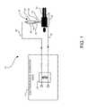
- FIG. 1is an illustration of an exemplary monopolar electrosurgical system in accordance with an embodiment of the present disclosure
- FIG. 2Ais a schematic diagram of an electrosurgical apparatus in accordance with an embodiment of the present disclosure
- FIG. 2Bis a cross sectional view of the electrosurgical apparatus shown in FIG. 2A taken along line A-A;
- FIG. 3Ais an enlarged cross sectional view of the electrosurgical apparatus in accordance with an embodiment of the present disclosure
- FIG. 3Billustrates a front view of the electrosurgical apparatus shown in FIG. 3A taken along line B-B;
- FIG. 4is an enlarged cross sectional view of the electrosurgical apparatus shown in FIG. 3A with a blade extended;
- FIG. 5is a side perspective view of an electrosurgical apparatus in accordance with another embodiment of the present disclosure.
- FIG. 6is an electrical schematic diagram of the electrosurgical apparatus shown in FIG. 5 ;
- FIG. 7is an electrical schematic diagram of an electrosurgical generator in accordance with an embodiment of the present disclosure.
- FIG. 8illustrates a generalized generator unit's output power curve
- FIG. 9is an electrical schematic diagram of an electrosurgical generator in accordance with another embodiment of the present disclosure.
- FIG. 10illustrates an electrosurgical system in accordance with a further embodiment of the present disclosure.
- proximalwill refer to the end of the device, e.g., instrument, apparatus, applicator, handpiece, forceps, etc., which is closer to the user, while the term “distal” will refer to the end which is further from the user.
- distalwill refer to the end which is further from the user.
- the phrase “coupled”is defined to mean directly connected to or indirectly connected with through one or more intermediate components. Such intermediate components may include both hardware and software based components.
- FIG. 1shows an exemplary monopolar electrosurgical system generally indicated as 10 comprising an electrosurgical generator (ESU) generally indicated as 12 to generate power for the electrosurgical apparatus 10 and a plasma generator generally indicated as 14 to generate and apply a plasma stream 16 to a surgical site or target area 18 on a patient 20 resting on a conductive plate or support surface 22 .
- the electrosurgical generator 12includes a transformer generally indicated as 24 including a primary and secondary coupled to an electrical source (not shown) to provide high frequency electrical energy to the plasma generator 14 .
- the electrosurgical generator 12comprises an isolated floating potential not referenced to any potential. Thus, current flows between the active and return electrodes. If the output is not isolated, but referenced to “earth”, current can flow to areas with ground potential. If the contact surface of these areas and the patient is relatively small, an undesirable burning can occur.
- the plasma generator 14comprises a handpiece or holder 26 having an electrode 28 at least partially disposed within a fluid flow housing 29 and coupled to the transformer 24 to receive the high frequency electrical energy therefrom to at least partially ionize noble gas fed to the fluid flow housing 29 of the handpiece or holder 26 to generate or create the plasma stream 16 .
- the high frequency electrical energyis fed from the secondary of the transformer 24 through an active conductor 30 to the electrode 28 (collectively active electrode) in the handpiece 26 to create the plasma stream 16 for application to the surgical site 18 on the patient 20 .
- a current limiting capacitor 25is provided in series with the electrode 28 to limit the amount of current being delivery to the patient 20 .
- the return path to the electrosurgical generator 12is through the tissue and body fluid of the patient 20 , the conductor plate or support member 22 and a return conductor 32 (collectively return electrode) to the secondary of the transformer 24 to complete the isolated, floating potential circuit.
- the electrosurgical generator 12comprises an isolated non-floating potential not referenced to any potential.
- the plasma current flow back to the electrosurgical generator 12is through the tissue and body fluid and the patient 20 . From there, the return current circuit is completed through the combined external capacitance to the plasma generator handpiece 26 , surgeon and through displacement current.
- the capacitanceis determined, among other things, by the physical size of the patient 20 .
- Such an electrosurgical apparatus and generatorare described in commonly owned U.S. Pat. No. 7,316,682 to Konesky, the contents of which are hereby incorporated by reference.
- transformer 24may be disposed in the plasma generator handpiece 26 , as will be described in various embodiments below.
- other transformersmay be provided in the generator 12 for providing a proper voltage and current to the transformer in the handpiece, e.g., a step-down transformer, a step-up transformer or any combination thereof.
- the apparatus 100includes a housing 102 having a proximal end 103 and a distal end 105 and a tube 104 having an open distal end 106 and a proximal end 108 coupled to the distal end 105 of the housing 102 .
- the housing 102includes a right side housing 110 and left side housing 112 , and further includes provisions for a button 114 and slider 116 . Activation of the slider 116 will expose a blade 118 at the open distal end 106 of the tube 104 . Activation of the button 114 will apply electrosurgical energy to the blade 118 and, in certain embodiments, enable gas flow through the flow tube 122 , as will be described in detail below.
- a transformer 120is provided on the proximal end 103 of the housing for coupling a source of radio frequency (RF) energy to the apparatus 100 .
- RFradio frequency
- FIG. 2BA cross section view along line A-A of the apparatus 102 is shown in FIG. 2B .
- flow tube 122Disposed within the housing 102 and tube 104 is flow tube 122 which runs along the longitudinal axis of the apparatus 100 .
- the blade 118is retained within the flow tube 122 .
- a proximal end 126 of the flow tube 122is coupled to a source of gas via a tube connector 128 and flexible tubing 129 .
- the proximal end 126 of the flow tube 122is also coupled to a source of RF energy via plug 130 which couples to transformer 120 .
- the flow tube 122is made of an electrically conducting material, preferably stainless steel, as to conduct the RF energy to the blade 118 when being employed for plasma applications or electrosurgical cutting as will be described below.
- the outer tube 104is constructed from non-conductive material, e.g., Lestran.
- the slider 116is coupled to the flow tube 122 via a retaining collar 132 .
- a printed circuit board (PCB) 134is disposed in the housing 102 and controls the application of the RF energy from the transformer 120 via the button 114 .
- the slider 116may be freely moveable in a linear direction or may include a mechanism for incremental movements, e.g., a ratchet movement, to prevent an operator of the apparatus 100 from over extending the blade 118 .
- a mechanism for incremental movements of the blade 118the operator will have greater control over the length of the exposed blade 118 to avoid damage to tissue at the surgical site.
- FIG. 2BAn enlarged view of the distal end 106 of the outer tube 104 is also illustrated in FIG. 2B .
- the blade 118is coupled to the flow tube 122 which is held in place in the outer tube 104 by at least one seal 136 .
- the at least one seal 136prevents backflow of gas into tube 104 and housing 102 .
- a cylindrical ceramic insert 138is disposed in the distal end of the outer tube 104 to maintain the blade along the longitudinal axis of the apparatus 100 and provide structural support during mechanical cutting when the blade is exposed beyond the distal end of the outer tube 104 .
- FIGS. 3A and 3Bshow an enlarged cross section of the apparatus and FIG. 3B illustrates a front view of the apparatus.
- the flow tube 122is disposed in the outer tube 104 with a cylindrical insulator 140 disposed around the flow tube 122 .
- Slider 116is coupled to the insulator 140 and is employed to extend and retract the blade 118 .
- the annular or ring shaped seal 136 and cylindrical ceramic insert 138are disposed about the flow tube 122 .
- the generally planar blade 118is coupled to an inner circumference of the cylindrical flow tube 122 such that two gas passageways 142 , 144 are formed on the both sides of the blade 118 .
- the gaswill pass over the blade 118 out the distal end 106 of the outer tube 104 .
- the apparatus 100When the blade is in the retracted position as shown in FIG. 3A , the apparatus 100 is suitable for generating plasma.
- RF energyis conducted to a tip 146 of the blade 118 from an electrosurgical generator (not shown) via the flow tube 122 .
- An inert gassuch as helium or argon, is then supplied to the flow tube from either the electrosurgical generator or an external gas source. As the inert gas flows over the sharp point 146 of the blade 118 held high voltage and high frequency, a cold plasma beam is generated.
- the blade 118is advanced, via slider 116 , so the tip 146 is extended past the distal end 106 of the outer tube 104 .
- the blade 118can be used for two cutting modes: mechanical cutting and electrosurgical cutting.
- mechanical cutting modeRF or electrosurgical energy is not applied to the flow tube 122 or blade 118 , and therefore, the blade 118 is in a de-energized state.
- the blade 118can be used excise tissue via mechanical cutting. After the tissue is removed, the blade 118 may be retracted via the slider 116 and electrosurgical energy and gas may be applied via button 114 to generate a cold plasma beam for cauterization, sterilization and/or hemostasis of the operative patient site.
- the blade 118In the electrosurgical cutting mode, the blade 118 is advanced and used while both electrically energized and with inert gas flow. This configuration resembles an electrosurgical knife approach, where the electrosurgical energy does the cutting. However, with the addition of the inert gas flow, cuts made show virtually no eschar, with very little collateral damage along the side walls of the cut. The cutting speed is considerably faster, with less mechanical cutting resistance as compared to when the knife blade is not electrically energized, i.e., the mechanical cutting mode. Hemostasis is also affected during this process.
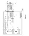
- the apparatus 200includes a housing 202 having a proximal end 203 and a distal end 205 and a tube 204 having an open distal end 206 and a proximal end 208 coupled to the distal end 205 of the housing 202 , thereby forming a handpiece.
- the housing 202includes a plurality of buttons 207 , e.g., buttons 214 , 215 and 219 , and a first slider 216 and second slider 221 . Activation of the first slider 216 will expose a blade 218 at the open distal end 206 of the tube 204 , as described above.
- Activation of the second slider 221sets the apparatus into different modes, as will be described below.
- Activation of the individual buttons 214 , 215 , 219will apply electrosurgical energy to the blade 218 to affect different electrosurgical modes and, in certain embodiments, enable gas flow through an internal flow tube 222 , as will be described in detail below.
- a transformer assembly 220is provided on the proximal end 203 of the housing 202 for coupling a source of radio frequency (RF) energy to the apparatus 200 via cable 260 and connector 262 .
- the cable 260includes a plurality of conductors for providing electrosurgical energy to the apparatus 200 and for communication signals to and from the apparatus 200 and an RF source, e.g., an electrosurgical generator 223 .
- the connector 262includes various pins, e.g., pins 281 , 282 , 283 , 284 , 286 , 288 and 290 , for coupling the connector 262 to corresponding port 225 on the generator 223 , the details of which will be described below.
- the electrosurgical generator 223includes a DC power supply 272 , an oscillator 273 , a power amplifier 274 , a step-down transformer 275 and a step-up transformer 276 for supplying power to the apparatus 200 .
- the electrosurgical generator 223further includes a controller 277 and memory 278 .
- the transformer assembly 220includes transformer T 1 264 , e.g., a step-up transformer, and at least one switch 266 , which is controlled by the second slider 221 .
- the switch 266is coupled on one end to the conductive flow tube 222 and the other end of the switch 266 is adjustable between an output of transformer 264 and an output received directly from the generator 223 via pin 283 , e.g., signal POWER_RF_MONO/ACTIVE_COMMON.
- the switch 266is controlled by the second slider 221 located on the external surface of the housing 202 .
- the second slider 221may include a mechanism to lock the slider 221 in a particular position.
- the second slider 221controls the switch 266 and is interlocked to disable other buttons and/or sends signals to the generator 223 for selecting a mode.
- the switch 266may be coupled to the first slider 216 to select a mode based on the position of the conductive flow tube 222 and/or blade 218 .
- switch 266In a first position, switch 266 is coupled between terminal 2 and terminal 1 wherein an output of the transformer 264 is coupled to the conductive flow tube 222 . In a second position, switch 266 is coupled between terminal 3 and terminal 1 wherein an output of the generator 223 , i.e., an external source, is coupled to the conductive flow tube 222 .
- switch 266is to have very low stray capacitance between terminals 1 and 2 and terminals 1 and 3 to avoid mutual coupling of the transformer 264 and the lines from the generator.
- Step-up transformers 264 and 276are both operated from the output of step-down transformer 275 , so their outputs can be configured as to be in-phase.
- the potential difference between switch 266 contacts 2 and 3can be small, depending on the load placed on either of those transformers. This will minimize potential arc-over between those contacts.
- Stray capacitancemay, in general, be minimized by using a small contact area for contacts 2 and 3 of switch 266 (comparable to the area of the plates of a capacitor) within the limits of their current carrying requirements. Maximizing the distance between contacts 2 and 3 of switch 266 when it is in an open state will also reduce stray capacitance (comparable to the distance between two plates of a capacitor).
- switch 268determines the position of switch 268 .
- Switch 268is coupled to the connector 262 via a conductor, e.g., SLIDER_POSITION_RECG, which signals the generator as to the position of the blade 218 via pin 290 . It is to be appreciated that switch 268 may be toggled between an open and closed position by being either directly or indirectly coupled to the slider 216 or the conductive flow tube 222 .
- buttons 214 , 215 , 219will apply electrosurgical energy to the blade 218 to affect different electrosurgical modes depending on the position of the blade 218 .
- button 214is configured for activating the J-Plasma mode
- button 215is configured for activating a COAG (or coagulation) mode
- button 219is configured for activating a CUT mode.
- Two wires or conductors 291 , 292are used to recognize which of the buttons or switches 214 , 215 or 219 are closed or activated.
- wire 291 coupled to pin 283is also employed for applying RF power to blade 218 when switch 266 is coupled between terminal 3 and terminal 1 wherein an output of the generator 223 is coupled to the conductive flow tube 222 .
- the other wirei.e., wire 292 coupled to pin 284 , is employed to allow controller 277 to sense which switch or button 214 , 215 or 219 is activated.
- the controller 277senses approximately 0 ohms; when switch 215 is activated, the controller 277 senses the parallel combination of resistor R 2 and capacitor C 5 at a given frequency; and when switch 219 is activated, the controller 277 senses the parallel combination of resistor R 1 and capacitor C 4 at a given frequency
- the J-Plasma modeis selected.
- the J-Plasma button 214is enabled while the COAG button 215 and CUT button 219 are mechanically and/or electrically disabled.
- the COAG button 215 and CUT button 219may be mechanically disabled by a switch, relay, etc.
- switch 266is coupled between terminal 2 and terminal 1 wherein an output of the transformer 264 is coupled to the conductive flow tube 222 .
- switch 268is closes, which signals the controller 277 in the generator 223 as to the position of the blade 218 and that the handpiece is in J-Plasma mode.
- a signalis sent to the generator 223 via pin 284 , e.g., ACT_JPLASMA/ACT_COAG/ACT_CUT, to initiate plasma generation.
- the generatorsupplies power via pin 286 along line RF 1 _JPL and via pin 288 along line RF 2 _JPL, via the step-down transformer 275 which provides power to step-up transformer 264 .
- activation of button 214initiates the flow of gas through the conductive flow tube 222 .
- the generator 223 coupled to the handpiece 200may include an internal gas flow controller which receives the signal.
- the gas flow controlleris located externally of the generator 223 but may receive the gas activation signal from the generator. In a further embodiment, the gas flow controller is located externally of the generator 223 but may receive the gas activation signal from the handpiece itself via hardwired or wireless means.
- the COAG/CUT modeis selected, also known as the general electrosurgery mode.
- the COAG button 215 and CUT button 219are enabled while the J-Plasma button 214 is mechanically and/or electrically disabled.
- the J-Plasma button 214may be mechanically disabled by a switch, relay, etc.
- switch 266is coupled between terminal 3 and terminal 1 wherein an output of the step-up transformer 276 in the generator 223 is coupled to the conductive flow tube 222 , i.e., the transformer 264 is bypassed.
- buttons 215 or 219Upon activation of buttons 215 or 219 , a signal is sent to the generator via line ACT_JPLASMA/ACT_COAG/ACT_CUT to initiate supply of electrosurgical energy. Subsequently, the generator supplies power via pin 283 along line POWER_RF MONO/ACTIVE COMMON, which provides power to the conductive flow tube 222 .
- the two step-up transformers 264 , 276i.e., transformer 264 in the handpiece 200 for the J-Plasma mode and transformer 276 in the generator 223 for the general electrosurgery mode
- transformer 264 in the handpiece 200will put out higher voltages than the electrosurgery transformer 276 in the generator 223 , but the J-Plasma transformer 264 is also matched for a higher output impedance for the combined tissue load and the plasma beam impedances in series.
- the electrosurgery transformer 276 back in the generator 223has a lower output voltage, but higher current capability and its output impedance is matched to the lower impedance value of an electrosurgical blade 218 in direct contact with tissue.
- Exemplary values for the output in J-Plasma modeare 10 kilo ohm output impedance, 4 kV to 6 kV peak-to-peak and 140 mA, where the exemplary values for the output in electrosurgery mode are 150-250 ohm output impedance, 300 V to 6.5 kV peak-to-peak and 1.5 Amps. It is to be appreciated these exemplary values are for illustrative purposes only and in use the values may vary.
- gasmay be provided to the handpiece 200 when in COAG/CUT mode.
- a mode buttonmay be provided on the generator to enable gas to flow, e.g., CUT with gas.
- fulguration or fulguration with gasmay be enabled from a button in the generator.
- the connector 262includes a one-wire chip 270 , e.g., a memory, including information associated with the handpiece or applicator so the generator may recognize the handpiece.
- the controller 277 of generator 223reads the information contained on the chip 270 and may perform or execute instructions based on the handpiece type.
- the chip 270may have read/write capabilities where the chip 270 can store how many times the handpiece has been used and provide that information to the generator.
- the controller 277 of generator 223may store or write the number of uses of the apparatus 200 in memory 278 and determine that the handpiece 200 may no longer be used based on a predetermined use limit.
- the chip 270may store application specific information for the handpiece that is to be loaded into the generator, e.g., a specific power profile of the handpiece.
- the chip 270may store information relating to the gas type to be used with the handpiece, e.g., Argon, Helium, etc.
- the generatormay provide an indication (or prevent operation) if the gas supplied does not match the type designated for the handpiece.
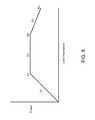
- the chip 270may store application specific information for the handpiece that is to be loaded into the generator, e.g., a specific power profile of the handpiece. While maximum and/or minimum power preset values establish overall operational boundaries for a given applicator, greater applicator safety and effectiveness can be realized by a pre-defined power curve specific to an applicator class or even a particular individual applicator. Typically, a power curve shows the relationship between the generator unit's output power and the load impedance. A generalized power curve is illustrated in FIG. 8 .
- the power curvecan be approximated by three segments.
- the firstis the constant current segment, shown as S 1 in FIG. 8 .
- the internal output impedance of the generator unitlimits the output power under this heavily loaded condition.
- Nextis the constant power segment, S 2 FIG. 8 , where the load impedance more closely matches the generator unit's internal output impedance.
- Lastis the constant voltage segment, S 3 in FIG. 8 , where the load impedance is significantly higher than the generator unit's output impedance.
- Electrosurgical applicator working electrodesmay have different surface areas, or plasma-beam applicators may have different beam diameters, configurations, or beam lengths which require associated power curves for enhanced safety and effectiveness.
- the automatic applicator identifiercan contain a power curve specific to that applicator class or even tailored to a given particular applicator. This applicator-specific power curve information is downloaded to the generator unit 223 , which then modifies its operational output power curve to match the requirements of a given applicator. Note that the generator unit's intrinsic output power curve represents a maximum overall set of values, from which the downloaded requested power curve can be a reduced value subset.
- the stored power curve in the automatic applicator identifiercan consist of a potentially large array of data points from which the required power curve can be reconstructed by the generator unit.
- a more compact representation, as illustrated in FIG. 8need only contain the three breakpoints B 1 , B 2 , and B 3 of the associated three segments S 1 , S 2 , and S 3 respectively.
- another stored power curvemay describe a relationship between a displayed value of a selected power setting to an internal pulse width within the generator unit, which, in turn, produces a specific power output. It is to be appreciated that this power curve would include that same general features as the above described power curve, i.e., this power curve will have segments and breakpoints similar to those illustrated in FIG. 8 . This power curve may also be stored as a look-up table.
- the chip 270may store information relating to the gas type to be used with the handpiece, e.g., Argon, Helium, etc.
- the generator or ancillary devicedetermines if the gas supplied matches the gas type designated for the handpiece as indicated by the chip 270 .
- Systems and methods for determining a gas typeare disclosed in commonly owned U.S. Patent Publication No. 2014/0005665, the contents of which are hereby incorporated by reference.
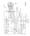
- an electrosurgical system 300is illustrated including an electrosurgical generator (ESU) 223 , a gas discriminator 322 and a connector of an electrosurgical handpiece 262 , e.g., a plasma generator.
- ESUelectrosurgical generator
- gas discriminator 322shown in FIG.
- the gas discriminator 322generally includes a gas input 324 coupled to a gas supply 325 , a gas output 326 and a detector/controller 328 coupled to a tube or chamber 330 for detected a type of gas flowing therethrough.
- the detector/controller 328provides an output control signal 332 , for example, indicative of the gas type, a GO signal, No Go signal, etc.
- the output control signal 332is transmitted to the controller 277 of the electrosurgical generator 223 .
- the electrosurgical generator 223further includes a flow controller 334 for controlling the flow of gas to an electrosurgical handpiece.
- the flow controller 334is coupled to the controller 277 and receives control signals from the controller 277 based on an algorithm or software function stored in memory 278 .
- the flow controller 334may receive a control signal from the controller 277 based on a second control signal, e.g., signal 332 , received at the controller 277 from the gas discriminator 322 .
- a second control signale.g., signal 332
- the controller 277upon coupling an electrosurgical handpiece via connector 262 to generator 223 , the controller 277 reads from the chip 270 the type of gas to be used with a specific handpiece. The controller 277 then transmits the gas type to the gas discriminator 322 .
- the gas discriminator 322determines that an expected gas is fed into the gas discriminator 322 and/or handpiece, the gas discriminator 322 transmits a “Go” signal to the controller 277 which subsequently enables the flow controller 334 and enables the RF output stage.
- the gas discriminator 322determines that the gas fed into the gas discriminator 322 and/or handpiece is a gas other than the expected gas, the gas discriminator 322 transmits a “No Go” signal to the controller 277 which subsequently disables the flow controller 334 and disables the RF output stage.
- the control signal 332may simply cause the electrosurgical generator to shutdown the RF output stage in certain embodiments where a flow controller 334 is not provided. It is to be further appreciated that the control signal 332 generated by the gas discriminator 322 may be coupled to the handpiece to disable the handpiece when necessary.
- the gas discriminator 322determines the type of gas, e.g., Helium, Argon, etc., and transmits the determined gas type to controller 277 .
- the controller 277determines if the determined gas type matches the specific gas type for the handpiece as read from the chip 270 . If the gas types match, the controller 277 enables operation of the generator and handpiece; otherwise, the controller 277 disables the generator and/or handpiece.
- Other methods to disable or stop an electrosurgical procedure, device or apparatus via the output of the gas discriminatorare contemplated to be within the scope of the present disclosure.
- gas discriminator 322may be coupled externally to electrosurgical generator 223 (for example, as shown in FIG. 9 ). Alternatively, it is to be appreciated that, in other embodiments, gas discriminator 322 may be disposed within electrosurgical generator 223 .
- Certain types of medical device applicatorsmay have tuned resonant elements within the applicator. It is often a difficult and time consuming task to fine tune the resonant elements in the applicator to match the output frequency of the generator unit for optimum performance, safety, and effectiveness. Small manufacturing variations in the applicator can have significant impact in performance, especially where the resonant Q factor is high.
- the actual resonant frequency of the applicatoris measured, and the measured value is stored in the automatic applicator identifier chip 270 in accordance with the present disclosure. The measured resonant frequency value of the applicator is downloaded to the generator unit and is then used to fine tune at least one frequency component of the generator unit to optimize the performance of that particular applicator.
- the resonant frequency of the high voltage output transformere.g., step-up transformers 264 . Due to the high resonant Q of this transformer, a slight mismatch of generator operating frequency and resonant frequency of a given transformer will produce significant reduction in the output voltage, affecting overall performance. The effect of manufacturing tolerances from one transformer to another, which would otherwise be insignificant, are magnified by the high Q factor of these transformers. Rather than meticulously attempt to trim the resonant frequency of each transformer individually, to match the operating frequency of the generator, the actual resonant frequency of each transformer is determined, and this value is stored in the identifier chip 270 .
- This valueis then read by the controller 277 of generator 223 , which adjusts its operating frequency to match that of a particular transformer.
- the generator's operating frequencyis adjusted via oscillator 273 although other methods to adjust the frequency are contemplated to be within the scope of the present disclosure.
- applicator 200includes at least one reactive switching element 293 , 295 to employ a multi-button activation scheme.
- An exemplary multi-button activation schemeis shown and described in commonly-owned U.S. Patent Publication No. 2014/0018795, the contents of which are hereby incorporated by reference.
- U.S. Patent Publication No. 2014/0018795describes a multi-button activation scheme where at least three input buttons are disposed on a housing of an applicator while minimizing the number of wires or conductors between the applicator and generator.
- input buttons 214 , 215 , 219are coupled to reactive switching elements 293 , 295 which are further coupled to activation sense circuits (not shown) disposed in the generator.
- the activation sense circuitsare configured to distinguish which input button has been activated.
- the activation sense circuitsinclude an oscillator, where a frequency of the oscillator is tuned to be in resonance with the reactive switching elements of the applicator.
- the resonant frequency value of the reactive switching elements of a particular applicatorare determined and store in the chip 270 .
- a controller 277 of the generatorUpon coupling the applicator to an appropriate generator, a controller 277 of the generator reads the resonant frequency values for the particular applicator and tunes the frequency of the activation sense circuit in the generator.
- the automatic applicator identifier chip or memory 270has read/write capabilities. Having read/write capabilities enables an electrosurgical generator to write data or values to the chip 270 . For example, upon coupling the applicator to the electrosurgical generator, an initial start time of the applicator may be written to the chip 270 by the electrosurgical generator. In one embodiment, a timestamp is sent to the chip, and stored therein, during an initial handshake between the applicator and generator. The timestamp may then be read from the chip 270 by the electrosurgical generator to determine accumulated run time, activation duration, elapsed time from first use, etc.
- the determined accumulated run timemay then be compared by the controller 277 to a maximum accumulated runtime, which is also stored on the chip 270 , to determine if this maximum has been reached for the applicator.
- a maximum activation durationmay be read from the chip 270 and compared to the activation duration as determined by the electrosurgical generator.
- the electrosurgical generatormay disable the applicator when certain predetermined limits or maximums are reached.
- a portion of the chip 270may be designated as a counter where the electrosurgical generator updates the counter upon, for example, each use of the applicator, each use of the applicator for a specific procedure, each activation of the applicator, etc.
- the electrosurgical generatormay reads a specific counter along with an associated predetermined maximum to determine if the maximum value has been exceeded to disable the applicator. For example, upon each activation of the applicator, the electrosurgical generator updates an associated activation counter in chip 270 . Prior to a subsequent activation, the electrosurgical generator reads a predetermined maximum number of activations stored on the chip 270 and compares the activation counter to the predetermined maximum. If the activation counter exceeds the predetermined maximum number of activations, the electrosurgical generator may disable the applicator or not provide power thereto.
- the automatic applicator identifier chip or memorywirelessly communicates to the generator.
- the wireless connectionwill operate under any of the various wireless protocols including but not limited to BluetoothTM interconnectivity, infrared connectivity, radio transmission connectivity including computer digital signal broadcasting and reception commonly referred to as Wi-Fi or 802.11.X (where x denotes the type of transmission), or any other type of communication protocols, communication architecture or systems currently existing or to be developed for wirelessly transmitting data including spread spectrum 900 MHz, or other frequencies, Zigbee, or any mesh enabled wireless communication.
- an electrosurgical apparatus 400in accordance with another embodiment of the present disclosure is illustrated.
- the applicator or handpiece 401is coupled to electrosurgical generator 423 via cable 460 and connector 462 .
- the connector 462includes a chip or memory 470 , as described above, coupled to a wireless transceiver 471 .
- the generator 423further includes a communication device 479 configured to wirelessly communicate with the transceiver 471 . In use, the communication device 479 receives data from the transceiver 471 and sends the received data to the controller 477 to achieve at least the various control modes described above.
- an external wireless adapter 480may be coupled to the generator 423 via an appropriate communication port 482 , e.g., a USB port, FireWire port, etc.
- the external wireless adapter 480communicates wirelessly to transceiver 471 and sends the data received from the transceiver 471 to controller 477 .
- the communication device 479 of generator 423enables communications to a server or other computing device for reporting details of the use of a particular applicator to ensure traceability of the applicator.
- the communication device 479may be a modem, network interface card (NIC), wireless transceiver, etc.
- the communication device 479will perform its functionality by hardwired and/or wireless connectivity.
- the hardwire connectionmay include but is not limited to hard wire cabling e.g., parallel or serial cables, RS232, RS485, USB cable, Firewire ( 1394 connectivity) cables, Ethernet, and the appropriate communication port configuration.
- the wireless connectionwill operate under any of the various wireless protocols including but not limited to BluetoothTM interconnectivity, infrared connectivity, radio transmission connectivity including computer digital signal broadcasting and reception commonly referred to as Wi-Fi or 802.11.X (where x denotes the type of transmission), satellite transmission or any other type of communication protocols, communication architecture or systems currently existing or to be developed.
- BluetoothTM interconnectivityinfrared connectivity
- radio transmission connectivityincluding computer digital signal broadcasting and reception commonly referred to as Wi-Fi or 802.11.X (where x denotes the type of transmission), satellite transmission or any other type of communication protocols, communication architecture or systems currently existing or to be developed.
- the generator 423may be connected to a communications network 484 , e.g., the Internet, by any means, for example, a hardwired or wireless connection, such as dial-up, hardwired, cable, DSL, satellite, cellular, PCS, wireless transmission (e.g., 802.11a/b/g), etc.
- the networkmay be a local area network (LAN), wide area network (WAN), the Internet or any network that couples a plurality of computers to enable various modes of communication via network messages.
- the serverwill communicate using various protocols such as Transmission Control Protocol/Internet Protocol (TCP/IP), File Transfer Protocol (FTP), Hypertext Transfer Protocol (HTTP), etc. and secure protocols such as Hypertext Transfer Protocol Secure (HTTPS), Internet Protocol Security Protocol (IPSec), Point-to-Point Tunneling Protocol (PPTP), Secure Sockets Layer (SSL) Protocol, etc.
- TCP/IPTransmission Control Protocol/Internet Protocol
- FTPFile Transfer Protocol
- HTTPHypertext Transfer Protocol
- HTTPSInternet Protocol Security Protocol
- the generator 423reads the unique identification identifier from chip 470 and transmits the identifier via the communication device 479 over the network 484 to a server or computing device 486 .
- Server 486may be maintained by a facility such as a hospital for inventory control. The server 486 may enter into a database and keep track of the number of uses of the applicator. In certain embodiments, the server 486 may determine if the applicator has reached a predetermined number of uses, and if so, the server 486 sends a control signal or command to the generator 423 to prevent use of the applicator and provide an local indication on a display of the generator.
- connector 262 / 462is not limited to use with the electrosurgical applicator described above.
- Connector 262 / 242may be configured to be used with many types of electrosurgical applicators, such as electrosurgical pencils, vessel sealers, etc.
- electrosurgical applicatorssuch as electrosurgical pencils, vessel sealers, etc.
- an exemplary electrosurgical applicatoris shown and described in commonly-owned U.S. Patent Publication No. 2014/0018795, the contents of which are hereby incorporated by reference.
Landscapes
- Health & Medical Sciences (AREA)
- Surgery (AREA)
- Engineering & Computer Science (AREA)
- Life Sciences & Earth Sciences (AREA)
- Biomedical Technology (AREA)
- Otolaryngology (AREA)
- Nuclear Medicine, Radiotherapy & Molecular Imaging (AREA)
- Plasma & Fusion (AREA)
- Physics & Mathematics (AREA)
- Heart & Thoracic Surgery (AREA)
- Medical Informatics (AREA)
- Molecular Biology (AREA)
- Animal Behavior & Ethology (AREA)
- General Health & Medical Sciences (AREA)
- Public Health (AREA)
- Veterinary Medicine (AREA)
- Surgical Instruments (AREA)
Abstract
Description
Claims (29)
Priority Applications (1)
| Application Number | Priority Date | Filing Date | Title |
|---|---|---|---|
| US14/715,847US9770285B2 (en) | 2010-11-08 | 2015-05-19 | System and method for identifying and controlling an electrosurgical apparatus |
Applications Claiming Priority (7)
| Application Number | Priority Date | Filing Date | Title |
|---|---|---|---|
| US41117410P | 2010-11-08 | 2010-11-08 | |
| US13/289,060US9060765B2 (en) | 2010-11-08 | 2011-11-04 | Electrosurgical apparatus with retractable blade |
| US201261667213P | 2012-07-02 | 2012-07-02 | |
| US201261716688P | 2012-10-22 | 2012-10-22 | |
| US13/802,572US9144453B2 (en) | 2010-11-08 | 2013-03-13 | Multi-mode electrosurgical apparatus |
| US13/802,227US9095333B2 (en) | 2012-07-02 | 2013-03-13 | Systems and methods of discriminating between argon and helium gases for enhanced safety of medical devices |
| US14/715,847US9770285B2 (en) | 2010-11-08 | 2015-05-19 | System and method for identifying and controlling an electrosurgical apparatus |
Related Parent Applications (2)
| Application Number | Title | Priority Date | Filing Date |
|---|---|---|---|
| US13/802,227Continuation-In-PartUS9095333B2 (en) | 2010-11-08 | 2013-03-13 | Systems and methods of discriminating between argon and helium gases for enhanced safety of medical devices |
| US13/802,572Continuation-In-PartUS9144453B2 (en) | 2010-11-08 | 2013-03-13 | Multi-mode electrosurgical apparatus |
Related Child Applications (1)
| Application Number | Title | Priority Date | Filing Date |
|---|---|---|---|
| US13/802,572Continuation-In-PartUS9144453B2 (en) | 2010-11-08 | 2013-03-13 | Multi-mode electrosurgical apparatus |
Publications (2)
| Publication Number | Publication Date |
|---|---|
| US20150257817A1 US20150257817A1 (en) | 2015-09-17 |
| US9770285B2true US9770285B2 (en) | 2017-09-26 |
Family
ID=54067669
Family Applications (1)
| Application Number | Title | Priority Date | Filing Date |
|---|---|---|---|
| US14/715,847ActiveUS9770285B2 (en) | 2010-11-08 | 2015-05-19 | System and method for identifying and controlling an electrosurgical apparatus |
Country Status (1)
| Country | Link |
|---|---|
| US (1) | US9770285B2 (en) |
Cited By (87)
| Publication number | Priority date | Publication date | Assignee | Title |
|---|---|---|---|---|
| US10251664B2 (en) | 2016-01-15 | 2019-04-09 | Ethicon Llc | Modular battery powered handheld surgical instrument with multi-function motor via shifting gear assembly |
| US10278721B2 (en) | 2010-07-22 | 2019-05-07 | Ethicon Llc | Electrosurgical instrument with separate closure and cutting members |
| US10285724B2 (en) | 2014-07-31 | 2019-05-14 | Ethicon Llc | Actuation mechanisms and load adjustment assemblies for surgical instruments |
| US10299810B2 (en) | 2010-02-11 | 2019-05-28 | Ethicon Llc | Rotatable cutting implements with friction reducing material for ultrasonic surgical instruments |
| US10335182B2 (en) | 2012-06-29 | 2019-07-02 | Ethicon Llc | Surgical instruments with articulating shafts |
| US10335183B2 (en) | 2012-06-29 | 2019-07-02 | Ethicon Llc | Feedback devices for surgical control systems |
| US10335614B2 (en) | 2008-08-06 | 2019-07-02 | Ethicon Llc | Devices and techniques for cutting and coagulating tissue |
| US10342602B2 (en) | 2015-03-17 | 2019-07-09 | Ethicon Llc | Managing tissue treatment |
| US10349999B2 (en) | 2014-03-31 | 2019-07-16 | Ethicon Llc | Controlling impedance rise in electrosurgical medical devices |
| US10376305B2 (en) | 2016-08-05 | 2019-08-13 | Ethicon Llc | Methods and systems for advanced harmonic energy |
| US10433900B2 (en) | 2011-07-22 | 2019-10-08 | Ethicon Llc | Surgical instruments for tensioning tissue |
| US10441310B2 (en) | 2012-06-29 | 2019-10-15 | Ethicon Llc | Surgical instruments with curved section |
| US10441345B2 (en) | 2009-10-09 | 2019-10-15 | Ethicon Llc | Surgical generator for ultrasonic and electrosurgical devices |
| US10456193B2 (en) | 2016-05-03 | 2019-10-29 | Ethicon Llc | Medical device with a bilateral jaw configuration for nerve stimulation |
| US10463421B2 (en) | 2014-03-27 | 2019-11-05 | Ethicon Llc | Two stage trigger, clamp and cut bipolar vessel sealer |
| US10485607B2 (en) | 2016-04-29 | 2019-11-26 | Ethicon Llc | Jaw structure with distal closure for electrosurgical instruments |
| US10517627B2 (en) | 2012-04-09 | 2019-12-31 | Ethicon Llc | Switch arrangements for ultrasonic surgical instruments |
| US10524872B2 (en) | 2012-06-29 | 2020-01-07 | Ethicon Llc | Closed feedback control for electrosurgical device |
| US10524854B2 (en) | 2010-07-23 | 2020-01-07 | Ethicon Llc | Surgical instrument |
| US10543008B2 (en) | 2012-06-29 | 2020-01-28 | Ethicon Llc | Ultrasonic surgical instruments with distally positioned jaw assemblies |
| US10555769B2 (en) | 2016-02-22 | 2020-02-11 | Ethicon Llc | Flexible circuits for electrosurgical instrument |
| US10575892B2 (en) | 2015-12-31 | 2020-03-03 | Ethicon Llc | Adapter for electrical surgical instruments |
| US10595930B2 (en) | 2015-10-16 | 2020-03-24 | Ethicon Llc | Electrode wiping surgical device |
| US10595929B2 (en) | 2015-03-24 | 2020-03-24 | Ethicon Llc | Surgical instruments with firing system overload protection mechanisms |
| US10610286B2 (en) | 2015-09-30 | 2020-04-07 | Ethicon Llc | Techniques for circuit topologies for combined generator |
| US10639092B2 (en) | 2014-12-08 | 2020-05-05 | Ethicon Llc | Electrode configurations for surgical instruments |
| US10646269B2 (en) | 2016-04-29 | 2020-05-12 | Ethicon Llc | Non-linear jaw gap for electrosurgical instruments |
| US10688321B2 (en) | 2009-07-15 | 2020-06-23 | Ethicon Llc | Ultrasonic surgical instruments |
| US10702329B2 (en) | 2016-04-29 | 2020-07-07 | Ethicon Llc | Jaw structure with distal post for electrosurgical instruments |
| US10716615B2 (en) | 2016-01-15 | 2020-07-21 | Ethicon Llc | Modular battery powered handheld surgical instrument with curved end effectors having asymmetric engagement between jaw and blade |
| US10729494B2 (en) | 2012-02-10 | 2020-08-04 | Ethicon Llc | Robotically controlled surgical instrument |
| US10765470B2 (en) | 2015-06-30 | 2020-09-08 | Ethicon Llc | Surgical system with user adaptable techniques employing simultaneous energy modalities based on tissue parameters |
| US10779845B2 (en) | 2012-06-29 | 2020-09-22 | Ethicon Llc | Ultrasonic surgical instruments with distally positioned transducers |
| US10779879B2 (en) | 2014-03-18 | 2020-09-22 | Ethicon Llc | Detecting short circuits in electrosurgical medical devices |
| US10835307B2 (en) | 2001-06-12 | 2020-11-17 | Ethicon Llc | Modular battery powered handheld surgical instrument containing elongated multi-layered shaft |
| US10856929B2 (en) | 2014-01-07 | 2020-12-08 | Ethicon Llc | Harvesting energy from a surgical generator |
| US10881449B2 (en) | 2012-09-28 | 2021-01-05 | Ethicon Llc | Multi-function bi-polar forceps |
| US10881444B2 (en) | 2010-11-08 | 2021-01-05 | Apyx Medical Corporation | Electrosurgical apparatus with retractable blade |
| US10898256B2 (en) | 2015-06-30 | 2021-01-26 | Ethicon Llc | Surgical system with user adaptable techniques based on tissue impedance |
| US10912580B2 (en) | 2013-12-16 | 2021-02-09 | Ethicon Llc | Medical device |
| US10912603B2 (en) | 2013-11-08 | 2021-02-09 | Ethicon Llc | Electrosurgical devices |
| US10925659B2 (en) | 2013-09-13 | 2021-02-23 | Ethicon Llc | Electrosurgical (RF) medical instruments for cutting and coagulating tissue |
| US10952788B2 (en) | 2015-06-30 | 2021-03-23 | Ethicon Llc | Surgical instrument with user adaptable algorithms |
| US10987123B2 (en) | 2012-06-28 | 2021-04-27 | Ethicon Llc | Surgical instruments with articulating shafts |
| US10993763B2 (en) | 2012-06-29 | 2021-05-04 | Ethicon Llc | Lockout mechanism for use with robotic electrosurgical device |
| US11051873B2 (en) | 2015-06-30 | 2021-07-06 | Cilag Gmbh International | Surgical system with user adaptable techniques employing multiple energy modalities based on tissue parameters |
| US11090104B2 (en) | 2009-10-09 | 2021-08-17 | Cilag Gmbh International | Surgical generator for ultrasonic and electrosurgical devices |
| US11129670B2 (en) | 2016-01-15 | 2021-09-28 | Cilag Gmbh International | Modular battery powered handheld surgical instrument with selective application of energy based on button displacement, intensity, or local tissue characterization |
| US11129669B2 (en) | 2015-06-30 | 2021-09-28 | Cilag Gmbh International | Surgical system with user adaptable techniques based on tissue type |
| US11179173B2 (en) | 2012-10-22 | 2021-11-23 | Cilag Gmbh International | Surgical instrument |
| US11229471B2 (en) | 2016-01-15 | 2022-01-25 | Cilag Gmbh International | Modular battery powered handheld surgical instrument with selective application of energy based on tissue characterization |
| US11266430B2 (en) | 2016-11-29 | 2022-03-08 | Cilag Gmbh International | End effector control and calibration |
| US11272973B2 (en) | 2015-01-28 | 2022-03-15 | Apyx Medical Corporation | Cold plasma electrosurgical apparatus with bent tip applicator |
| US11311326B2 (en) | 2015-02-06 | 2022-04-26 | Cilag Gmbh International | Electrosurgical instrument with rotation and articulation mechanisms |
| US11324527B2 (en) | 2012-11-15 | 2022-05-10 | Cilag Gmbh International | Ultrasonic and electrosurgical devices |
| US11337747B2 (en) | 2014-04-15 | 2022-05-24 | Cilag Gmbh International | Software algorithms for electrosurgical instruments |
| US11399855B2 (en) | 2014-03-27 | 2022-08-02 | Cilag Gmbh International | Electrosurgical devices |
| US11452525B2 (en) | 2019-12-30 | 2022-09-27 | Cilag Gmbh International | Surgical instrument comprising an adjustment system |
| US11589916B2 (en) | 2019-12-30 | 2023-02-28 | Cilag Gmbh International | Electrosurgical instruments with electrodes having variable energy densities |
| US11602390B2 (en) | 2017-01-30 | 2023-03-14 | Apyx Medical Corporation | Electrosurgical apparatus with flexible shaft |
| US11660089B2 (en) | 2019-12-30 | 2023-05-30 | Cilag Gmbh International | Surgical instrument comprising a sensing system |
| US11684412B2 (en) | 2019-12-30 | 2023-06-27 | Cilag Gmbh International | Surgical instrument with rotatable and articulatable surgical end effector |
| US11696776B2 (en) | 2019-12-30 | 2023-07-11 | Cilag Gmbh International | Articulatable surgical instrument |
| US11723716B2 (en) | 2019-12-30 | 2023-08-15 | Cilag Gmbh International | Electrosurgical instrument with variable control mechanisms |
| US11759251B2 (en) | 2019-12-30 | 2023-09-19 | Cilag Gmbh International | Control program adaptation based on device status and user input |
| US11779387B2 (en) | 2019-12-30 | 2023-10-10 | Cilag Gmbh International | Clamp arm jaw to minimize tissue sticking and improve tissue control |
| US11779329B2 (en) | 2019-12-30 | 2023-10-10 | Cilag Gmbh International | Surgical instrument comprising a flex circuit including a sensor system |
| US11786291B2 (en) | 2019-12-30 | 2023-10-17 | Cilag Gmbh International | Deflectable support of RF energy electrode with respect to opposing ultrasonic blade |
| US11812957B2 (en) | 2019-12-30 | 2023-11-14 | Cilag Gmbh International | Surgical instrument comprising a signal interference resolution system |
| US11877788B2 (en) | 2017-05-30 | 2024-01-23 | Apyx Medical Corporation | Electrosurgical apparatus with robotic tip |
| US11911063B2 (en) | 2019-12-30 | 2024-02-27 | Cilag Gmbh International | Techniques for detecting ultrasonic blade to electrode contact and reducing power to ultrasonic blade |
| EP4106778A4 (en)* | 2020-02-18 | 2024-02-28 | APYX Medical Corporation | Devices, systems and methods for sensing and discerning between fat and muscle tissue during medical procedures |
| US11937866B2 (en) | 2019-12-30 | 2024-03-26 | Cilag Gmbh International | Method for an electrosurgical procedure |
| US11937863B2 (en) | 2019-12-30 | 2024-03-26 | Cilag Gmbh International | Deflectable electrode with variable compression bias along the length of the deflectable electrode |
| US11944366B2 (en) | 2019-12-30 | 2024-04-02 | Cilag Gmbh International | Asymmetric segmented ultrasonic support pad for cooperative engagement with a movable RF electrode |
| US11950797B2 (en) | 2019-12-30 | 2024-04-09 | Cilag Gmbh International | Deflectable electrode with higher distal bias relative to proximal bias |
| US11986201B2 (en) | 2019-12-30 | 2024-05-21 | Cilag Gmbh International | Method for operating a surgical instrument |
| US12023086B2 (en) | 2019-12-30 | 2024-07-02 | Cilag Gmbh International | Electrosurgical instrument for delivering blended energy modalities to tissue |
| US12053224B2 (en) | 2019-12-30 | 2024-08-06 | Cilag Gmbh International | Variation in electrode parameters and deflectable electrode to modify energy density and tissue interaction |
| US12064109B2 (en) | 2019-12-30 | 2024-08-20 | Cilag Gmbh International | Surgical instrument comprising a feedback control circuit |
| US12076006B2 (en) | 2019-12-30 | 2024-09-03 | Cilag Gmbh International | Surgical instrument comprising an orientation detection system |
| US12082808B2 (en) | 2019-12-30 | 2024-09-10 | Cilag Gmbh International | Surgical instrument comprising a control system responsive to software configurations |
| US12114912B2 (en) | 2019-12-30 | 2024-10-15 | Cilag Gmbh International | Non-biased deflectable electrode to minimize contact between ultrasonic blade and electrode |
| US12193698B2 (en) | 2016-01-15 | 2025-01-14 | Cilag Gmbh International | Method for self-diagnosing operation of a control switch in a surgical instrument system |
| US12262937B2 (en) | 2019-12-30 | 2025-04-01 | Cilag Gmbh International | User interface for surgical instrument with combination energy modality end-effector |
| US12336747B2 (en) | 2019-12-30 | 2025-06-24 | Cilag Gmbh International | Method of operating a combination ultrasonic / bipolar RF surgical device with a combination energy modality end-effector |
| US12343063B2 (en) | 2019-12-30 | 2025-07-01 | Cilag Gmbh International | Multi-layer clamp arm pad for enhanced versatility and performance of a surgical device |
Families Citing this family (10)
| Publication number | Priority date | Publication date | Assignee | Title |
|---|---|---|---|---|
| WO2012158443A2 (en)* | 2011-05-13 | 2012-11-22 | Sheperak Thomas J | Plasma directed electron beam wound care system apparatus and method |
| CN110711026B (en) | 2014-09-05 | 2023-02-28 | 埃派克斯医疗公司 | Electrosurgical snare device |
| US11291491B2 (en) | 2016-05-05 | 2022-04-05 | I.C. Medical, Inc. | Electrosurgery blade and electrosurgery blade assembly |
| US20180014872A1 (en)* | 2016-07-15 | 2018-01-18 | Ethicon Endo-Surgery, Llc | Paired device and generator codes |
| US10792095B2 (en) | 2017-03-05 | 2020-10-06 | I.C. Medical, Inc. | Monopolar electrosurgery pencil with argon beam capability |
| GB2579644A (en)* | 2018-12-10 | 2020-07-01 | Creo Medical Ltd | A modular electrosurgical system, and modules for said system |
| US11317255B2 (en)* | 2019-05-07 | 2022-04-26 | T-Mobile Usa, Inc. | Cross network rich communications services content |
| BR112022011134A2 (en)* | 2019-12-07 | 2022-08-23 | Apyx Medical Corp | DEVICES, SYSTEMS AND METHODS FOR CALCULATION OF THE QUANTITY OF ENERGY DELIVERED TO THE TISSUE DURING ELECTROSURGICAL TREATMENT |
| US20210259759A1 (en)* | 2020-02-20 | 2021-08-26 | Covidien Lp | Electrosurgical system and methods of switching between distinct modes and power settings |
| WO2025101343A1 (en)* | 2023-11-08 | 2025-05-15 | Smith & Nephew, Inc. | Handheld rf generator with distal tip, hand, and foot control |
Citations (101)
| Publication number | Priority date | Publication date | Assignee | Title |
|---|---|---|---|---|
| US1813902A (en) | 1928-01-18 | 1931-07-14 | Liebel Flarsheim Co | Electrosurgical apparatus |
| US2435442A (en) | 1943-12-23 | 1948-02-03 | Gen Electric | Tuning arrangement for concentric transmission line resonators |
| US3239730A (en) | 1964-04-16 | 1966-03-08 | Farago George | Variable capacitor |
| US3801766A (en) | 1973-01-22 | 1974-04-02 | Valleylab Inc | Switching means for an electro-surgical device including particular contact means and particular printed-circuit mounting means |
| US4127110A (en) | 1976-05-24 | 1978-11-28 | Huntington Institute Of Applied Medical Research | Implantable pressure transducer |
| US4545375A (en) | 1983-06-10 | 1985-10-08 | Aspen Laboratories, Inc. | Electrosurgical instrument |
| US4580562A (en) | 1981-01-02 | 1986-04-08 | Goof Sven Karl Lennart | Electrosurgical apparatus |
| US4619258A (en) | 1984-03-02 | 1986-10-28 | Dart Industries Inc. | Electrosurgical pencil providing blade isolation |
| US4625723A (en) | 1985-02-26 | 1986-12-02 | Medical Research Associates, Ltd. #1 | Pencil for electrosurgical generator |
| US4632109A (en) | 1984-12-11 | 1986-12-30 | Valleylab, Inc. | Circuitry for processing requests made from the sterile field of a surgical procedure to change the output power level of an electrosurgical generator |
| US4708137A (en) | 1985-05-20 | 1987-11-24 | Olympus Optical Co., Ltd. | High-frequency incision device |
| US4827927A (en) | 1984-12-26 | 1989-05-09 | Valleylab, Inc. | Apparatus for changing the output power level of an electrosurgical generator while remaining in the sterile field of a surgical procedure |
| US5088997A (en) | 1990-03-15 | 1992-02-18 | Valleylab, Inc. | Gas coagulation device |
| US5098430A (en) | 1990-03-16 | 1992-03-24 | Beacon Laboratories, Inc. | Dual mode electrosurgical pencil |
| US5207675A (en) | 1991-07-15 | 1993-05-04 | Jerome Canady | Surgical coagulation device |
| US5256138A (en) | 1990-10-04 | 1993-10-26 | The Birtcher Corporation | Electrosurgical handpiece incorporating blade and conductive gas functionality |
| US5269780A (en) | 1990-10-12 | 1993-12-14 | Delma Elektro- Und Medizinische Apparatebau Gesellschaft Mbh | Electro-surgical devices |
| US5306238A (en) | 1990-03-16 | 1994-04-26 | Beacon Laboratories, Inc. | Laparoscopic electrosurgical pencil |
| US5400267A (en) | 1992-12-08 | 1995-03-21 | Hemostatix Corporation | Local in-device memory feature for electrically powered medical equipment |
| US5425375A (en) | 1993-09-09 | 1995-06-20 | Cardiac Pathways Corporation | Reusable medical device with usage memory, system using same |
| US5449356A (en) | 1991-10-18 | 1995-09-12 | Birtcher Medical Systems, Inc. | Multifunctional probe for minimally invasive surgery |
| US5626575A (en) | 1995-04-28 | 1997-05-06 | Conmed Corporation | Power level control apparatus for electrosurgical generators |
| US5647869A (en) | 1994-06-29 | 1997-07-15 | Gyrus Medical Limited | Electrosurgical apparatus |
| US5651780A (en) | 1991-11-08 | 1997-07-29 | Ep Technologies, Inc. | Systems for identifying catheters and monitoring their use |
| US5660657A (en) | 1995-01-31 | 1997-08-26 | Kimberly-Clark Worldwide, Inc. | Composite method for fabricating garments |
| US5693044A (en) | 1992-12-11 | 1997-12-02 | Cosmescu; Ioan | Telescopic surgical device and method therefor |
| US5693042A (en) | 1994-04-28 | 1997-12-02 | Ethicon Endo-Surgery, Inc. | Identification device for surgical instrument |
| US5776092A (en) | 1994-03-23 | 1998-07-07 | Erbe Elektromedizin Gmbh | Multifunctional surgical instrument |
| US5800427A (en) | 1996-12-26 | 1998-09-01 | Zamba; Gene | Electro-surgical blade |
| EP0878263A1 (en) | 1997-05-16 | 1998-11-18 | Illinois Tool Works Inc. | Welding machine |
| US6193715B1 (en) | 1999-03-19 | 2001-02-27 | Medical Scientific, Inc. | Device for converting a mechanical cutting device to an electrosurgical cutting device |
| US6225593B1 (en) | 1997-02-15 | 2001-05-01 | Helica Instruments Limited | Medical apparatus for generating an ionised gas plasma flame |
| US6293945B1 (en) | 2000-03-06 | 2001-09-25 | Everest Medical Corporation | Electrosurgical instrument with suction capability |
| US6325799B1 (en) | 1997-04-24 | 2001-12-04 | Gyrus Medical Limited | Electrosurgical instrument |
| US20020013582A1 (en) | 1995-02-22 | 2002-01-31 | Medtronic, Inc. | Medical device with porous metl element |
| US6391027B1 (en) | 1996-07-04 | 2002-05-21 | Erbe Elektromedizin Gmbh | Gas-aided, axially displaceable surgical electrode |
| US6409724B1 (en) | 1999-05-28 | 2002-06-25 | Gyrus Medical Limited | Electrosurgical instrument |
| US6458125B1 (en) | 1995-07-10 | 2002-10-01 | I. C. Medical, Inc. | Electro-surgical unit pencil apparatus and method therefor |
| US6475215B1 (en) | 2000-10-12 | 2002-11-05 | Naim Erturk Tanrisever | Quantum energy surgical device and method |
| US20030050633A1 (en) | 2001-09-13 | 2003-03-13 | Ellman Alan G. | Intelligent selection system for electrosurgical instrument |
| US6558383B2 (en) | 2000-02-16 | 2003-05-06 | Sherwood Services Ag | Inert gas inhanced electrosurgical apparatus |
| US6578579B2 (en) | 1999-09-07 | 2003-06-17 | Scimed Life Systems, Inc. | Systems and methods for preventing automatic identification of re-used single use devices |
| US20030130655A1 (en) | 1995-06-07 | 2003-07-10 | Arthrocare Corporation | Electrosurgical systems and methods for removing and modifying tissue |
| US6740079B1 (en) | 2001-07-12 | 2004-05-25 | Neothermia Corporation | Electrosurgical generator |
| US20040148903A1 (en) | 2000-04-24 | 2004-08-05 | Cash David W. | Method and apparatus for increasing the capacity and stability of a single-pole tower |
| WO2004096315A2 (en) | 2003-04-24 | 2004-11-11 | Northgate Technologies Inc. | Mixed-gas insufflation system |
| US20040243120A1 (en) | 1997-12-10 | 2004-12-02 | Orszulak James Henry | Smart recognition apparatus and method |
| US20050075630A1 (en) | 2000-08-01 | 2005-04-07 | Dfine, Inc. | Voltage threshold ablation apparatus |
| US6899538B2 (en) | 2000-07-19 | 2005-05-31 | J. Morita Manufacturing Corporation | Identification type instrument assembly, identification type adapter, identification type tube, and medical apparatus using them |
| US20050148903A1 (en) | 2002-03-05 | 2005-07-07 | Leonidas Diamantopoulos | Catheter |
| US6958063B1 (en) | 1999-04-22 | 2005-10-25 | Soring Gmbh Medizintechnik | Plasma generator for radio frequency surgery |
| US7033353B2 (en) | 1996-03-21 | 2006-04-25 | Sherwood Services Ag | Electrosurgical gas attachment |
| US20060122595A1 (en)* | 2002-09-04 | 2006-06-08 | Guenter Farin | Applicatior for an electrosurgical instrument |
| US7115121B2 (en) | 2001-06-08 | 2006-10-03 | Storz Endoskop Gmbh | Electrosurgical apparatus |
| US7156842B2 (en) | 2003-11-20 | 2007-01-02 | Sherwood Services Ag | Electrosurgical pencil with improved controls |
| US7156844B2 (en) | 2003-11-20 | 2007-01-02 | Sherwood Services Ag | Electrosurgical pencil with improved controls |
| US7169144B2 (en)* | 1998-07-07 | 2007-01-30 | Medtronic, Inc. | Apparatus and method for creating, maintaining, and controlling a virtual electrode used for the ablation of tissue |
| US20070028669A1 (en) | 2003-09-26 | 2007-02-08 | Brewster Barrie D | Detection of contaminants within fluid pumped by a vacuum pump |
| US20070049926A1 (en) | 2005-08-25 | 2007-03-01 | Sartor Joe D | Handheld electrosurgical apparatus for controlling operating room equipment |
| EP1764057A1 (en) | 2005-09-19 | 2007-03-21 | Sherwood Services AG | Portable argon system |
| US20070083247A1 (en) | 2005-10-11 | 2007-04-12 | Thermage, Inc. | Electrode assembly and handpiece with adjustable system impedance, and methods of operating an energy-based medical system to treat tissue |
| US20070135812A1 (en) | 2005-12-12 | 2007-06-14 | Sherwood Services Ag | Laparoscopic apparatus for performing electrosurgical procedures |
| US20070158209A1 (en) | 2006-01-05 | 2007-07-12 | Samsung Electronics Co., Ltd. | Gas sensor and method thereof |
| US7244257B2 (en) | 2002-11-05 | 2007-07-17 | Sherwood Services Ag | Electrosurgical pencil having a single button variable control |
| US7316682B2 (en) | 2002-12-17 | 2008-01-08 | Aaron Medical Industries, Inc. | Electrosurgical device to generate a plasma stream |
| US7335199B2 (en) | 2000-02-22 | 2008-02-26 | Rhytec Limited | Tissue resurfacing |
| US20080071261A1 (en) | 2006-09-20 | 2008-03-20 | Sherwood Services Ag | Electrosurgical radio frequency energy transmission medium |
| US20080108985A1 (en) | 2002-12-17 | 2008-05-08 | Konesky Gregory A | Electrosurgical device to generate a plasma stream |
| US20080140066A1 (en) | 2006-11-02 | 2008-06-12 | Davison Paul O | Electric plasma-mediated cutting and coagulation of tissue and surgical apparatus |
| US7443296B2 (en) | 2006-07-21 | 2008-10-28 | Alcon, Inc. | Smart connector system for surgical machine |
| US20090005772A1 (en) | 2007-06-28 | 2009-01-01 | Rhytec Limited | Tissue treatment apparatus |
| US7481809B2 (en) | 1996-01-05 | 2009-01-27 | Thermage, Inc. | Handpiece with RF electrode and non-volatile memory |
| US7503917B2 (en) | 2003-11-20 | 2009-03-17 | Covidien Ag | Electrosurgical pencil with improved controls |
| US20090125023A1 (en) | 2007-11-13 | 2009-05-14 | Cytyc Corporation | Electrosurgical Instrument |
| US20090149851A1 (en) | 2007-12-05 | 2009-06-11 | Tyco Healthcare Group Lp | Thermal Penetration and Arc Length Controllable Electrosurgical Pencil |
| US7568619B2 (en) | 2004-12-15 | 2009-08-04 | Alcon, Inc. | System and method for identifying and controlling ophthalmic surgical devices and components |
| US7578817B2 (en) | 2004-08-11 | 2009-08-25 | Jerome Canady | Combination argon plasma coagulation and electrocautery device and method |
| US20090248022A1 (en)* | 2008-03-31 | 2009-10-01 | Applied Medical Resources Corporation | Electrosurgical system |
| US20100094288A1 (en) | 2008-10-10 | 2010-04-15 | Tyco Healthcare Group Lp | System and Method for Delivering High Current to Electrosurgical Device |
| US7749221B2 (en) | 2005-08-23 | 2010-07-06 | Rontal Daniel A | Retractable electrosurgical electrode |
| US20100262139A1 (en) | 2007-12-12 | 2010-10-14 | Beller Juergen | Device for contactless communication and use of a memory device |
| EP2263728A2 (en) | 1998-05-19 | 2010-12-22 | Georgia Biomedical, Inc. | Method and apparatus for conditioning gas for medical procedures |
| US8016824B2 (en) | 2002-07-25 | 2011-09-13 | Covidien Ag | Electrosurgical pencil with drag sensing capability |
| US8022327B2 (en) | 2009-06-19 | 2011-09-20 | Michael Blomeyer | Switch, circuitry, and method of assembly for electrosurgical pencil |
| US20110238053A1 (en) | 2010-03-25 | 2011-09-29 | Vivant Medical, Inc. | Microwave Surface Coagulator with Retractable Blade |
| US20110276113A1 (en) | 2010-04-12 | 2011-11-10 | Cybulski James S | RF Tissue Modulation Devices and Methods of Using the Same |
| EP2449992A1 (en) | 2010-11-08 | 2012-05-09 | Bovie Medical Corporation | Electrosurgical apparatus with retractable blade |
| US8177782B2 (en) | 2006-04-05 | 2012-05-15 | Erbe Elektromedizin Gmbh | Connection cable |
| US20120123405A1 (en) | 2010-11-16 | 2012-05-17 | Tyco Healthcare Group Lp | Power Glove |
| US8216220B2 (en) | 2007-09-07 | 2012-07-10 | Tyco Healthcare Group Lp | System and method for transmission of combined data stream |
| US20120232540A1 (en) | 2011-03-10 | 2012-09-13 | Thomas Baur | Surgical instrument with digital data interface |
| US8319134B2 (en) | 2009-06-19 | 2012-11-27 | E Surgical, Llc | Electrosurgical pencil switch, circuitry, and method of assembly |
| US20120330305A1 (en) | 2008-03-27 | 2012-12-27 | Bovie Medical Corporation | Laparoscopic Electrosurgical Electrical Leakage Detection |
| US20120330307A1 (en) | 2011-06-23 | 2012-12-27 | Tyco Healthcare Group Lp | Shaped Electrode Bipolar Resection Apparatus, System and Methods of Use |
| US20130046290A1 (en) | 2008-11-06 | 2013-02-21 | Covidien Ag | Two-Stage Switch for Surgical Device |
| US20130237982A1 (en) | 2010-11-08 | 2013-09-12 | Bovie Medical Corporation | Multi-mode electrosurgical apparatus |
| US8568400B2 (en)* | 2009-09-23 | 2013-10-29 | Covidien Lp | Methods and apparatus for smart handset design in surgical instruments |
| US20130296846A1 (en) | 2010-11-02 | 2013-11-07 | U.S. Patent Innovations, LLC | System and Method for Electrosurgical Conductive Gas Cutting for Improving Eschar, Sealing Vessels and Tissues |
| US20140005665A1 (en) | 2012-07-02 | 2014-01-02 | Bovie Medical Corporation | Systems and methods of discriminating between argon and helium gases for enhanced safety of medical devices |
| US20140018795A1 (en) | 2010-11-08 | 2014-01-16 | Bovie Medical Corporation | Multi-button electrosurgical apparatus |
| US8689606B2 (en) | 2009-03-23 | 2014-04-08 | Koninklijke Philips N.V. | Gas sensing using ultrasound |
- 2015
- 2015-05-19USUS14/715,847patent/US9770285B2/enactiveActive
Patent Citations (113)
| Publication number | Priority date | Publication date | Assignee | Title |
|---|---|---|---|---|
| US1813902A (en) | 1928-01-18 | 1931-07-14 | Liebel Flarsheim Co | Electrosurgical apparatus |
| US2435442A (en) | 1943-12-23 | 1948-02-03 | Gen Electric | Tuning arrangement for concentric transmission line resonators |
| US3239730A (en) | 1964-04-16 | 1966-03-08 | Farago George | Variable capacitor |
| US3801766A (en) | 1973-01-22 | 1974-04-02 | Valleylab Inc | Switching means for an electro-surgical device including particular contact means and particular printed-circuit mounting means |
| US4127110A (en) | 1976-05-24 | 1978-11-28 | Huntington Institute Of Applied Medical Research | Implantable pressure transducer |
| US4580562A (en) | 1981-01-02 | 1986-04-08 | Goof Sven Karl Lennart | Electrosurgical apparatus |
| US4545375A (en) | 1983-06-10 | 1985-10-08 | Aspen Laboratories, Inc. | Electrosurgical instrument |
| US4619258A (en) | 1984-03-02 | 1986-10-28 | Dart Industries Inc. | Electrosurgical pencil providing blade isolation |
| US4632109A (en) | 1984-12-11 | 1986-12-30 | Valleylab, Inc. | Circuitry for processing requests made from the sterile field of a surgical procedure to change the output power level of an electrosurgical generator |
| US4827927A (en) | 1984-12-26 | 1989-05-09 | Valleylab, Inc. | Apparatus for changing the output power level of an electrosurgical generator while remaining in the sterile field of a surgical procedure |
| US4625723A (en) | 1985-02-26 | 1986-12-02 | Medical Research Associates, Ltd. #1 | Pencil for electrosurgical generator |
| US4708137A (en) | 1985-05-20 | 1987-11-24 | Olympus Optical Co., Ltd. | High-frequency incision device |
| US5088997A (en) | 1990-03-15 | 1992-02-18 | Valleylab, Inc. | Gas coagulation device |
| US5098430A (en) | 1990-03-16 | 1992-03-24 | Beacon Laboratories, Inc. | Dual mode electrosurgical pencil |
| US5306238A (en) | 1990-03-16 | 1994-04-26 | Beacon Laboratories, Inc. | Laparoscopic electrosurgical pencil |
| US5256138A (en) | 1990-10-04 | 1993-10-26 | The Birtcher Corporation | Electrosurgical handpiece incorporating blade and conductive gas functionality |
| US5269780A (en) | 1990-10-12 | 1993-12-14 | Delma Elektro- Und Medizinische Apparatebau Gesellschaft Mbh | Electro-surgical devices |
| US5207675A (en) | 1991-07-15 | 1993-05-04 | Jerome Canady | Surgical coagulation device |
| US5449356A (en) | 1991-10-18 | 1995-09-12 | Birtcher Medical Systems, Inc. | Multifunctional probe for minimally invasive surgery |
| US5651780A (en) | 1991-11-08 | 1997-07-29 | Ep Technologies, Inc. | Systems for identifying catheters and monitoring their use |
| US5400267A (en) | 1992-12-08 | 1995-03-21 | Hemostatix Corporation | Local in-device memory feature for electrically powered medical equipment |
| US5693044A (en) | 1992-12-11 | 1997-12-02 | Cosmescu; Ioan | Telescopic surgical device and method therefor |
| US5425375A (en) | 1993-09-09 | 1995-06-20 | Cardiac Pathways Corporation | Reusable medical device with usage memory, system using same |
| US5776092A (en) | 1994-03-23 | 1998-07-07 | Erbe Elektromedizin Gmbh | Multifunctional surgical instrument |
| US5693042A (en) | 1994-04-28 | 1997-12-02 | Ethicon Endo-Surgery, Inc. | Identification device for surgical instrument |
| US5647869A (en) | 1994-06-29 | 1997-07-15 | Gyrus Medical Limited | Electrosurgical apparatus |
| US5660657A (en) | 1995-01-31 | 1997-08-26 | Kimberly-Clark Worldwide, Inc. | Composite method for fabricating garments |
| US20020013582A1 (en) | 1995-02-22 | 2002-01-31 | Medtronic, Inc. | Medical device with porous metl element |
| US5626575A (en) | 1995-04-28 | 1997-05-06 | Conmed Corporation | Power level control apparatus for electrosurgical generators |
| US20030130655A1 (en) | 1995-06-07 | 2003-07-10 | Arthrocare Corporation | Electrosurgical systems and methods for removing and modifying tissue |
| US6770071B2 (en) | 1995-06-07 | 2004-08-03 | Arthrocare Corporation | Bladed electrosurgical probe |
| US6458125B1 (en) | 1995-07-10 | 2002-10-01 | I. C. Medical, Inc. | Electro-surgical unit pencil apparatus and method therefor |
| US7481809B2 (en) | 1996-01-05 | 2009-01-27 | Thermage, Inc. | Handpiece with RF electrode and non-volatile memory |
| US7033353B2 (en) | 1996-03-21 | 2006-04-25 | Sherwood Services Ag | Electrosurgical gas attachment |
| US6391027B1 (en) | 1996-07-04 | 2002-05-21 | Erbe Elektromedizin Gmbh | Gas-aided, axially displaceable surgical electrode |
| US5800427A (en) | 1996-12-26 | 1998-09-01 | Zamba; Gene | Electro-surgical blade |
| US6225593B1 (en) | 1997-02-15 | 2001-05-01 | Helica Instruments Limited | Medical apparatus for generating an ionised gas plasma flame |
| US6325799B1 (en) | 1997-04-24 | 2001-12-04 | Gyrus Medical Limited | Electrosurgical instrument |
| EP0878263A1 (en) | 1997-05-16 | 1998-11-18 | Illinois Tool Works Inc. | Welding machine |
| US20040243120A1 (en) | 1997-12-10 | 2004-12-02 | Orszulak James Henry | Smart recognition apparatus and method |
| EP2263728A2 (en) | 1998-05-19 | 2010-12-22 | Georgia Biomedical, Inc. | Method and apparatus for conditioning gas for medical procedures |
| US7169144B2 (en)* | 1998-07-07 | 2007-01-30 | Medtronic, Inc. | Apparatus and method for creating, maintaining, and controlling a virtual electrode used for the ablation of tissue |
| US6193715B1 (en) | 1999-03-19 | 2001-02-27 | Medical Scientific, Inc. | Device for converting a mechanical cutting device to an electrosurgical cutting device |
| US6958063B1 (en) | 1999-04-22 | 2005-10-25 | Soring Gmbh Medizintechnik | Plasma generator for radio frequency surgery |
| US6409724B1 (en) | 1999-05-28 | 2002-06-25 | Gyrus Medical Limited | Electrosurgical instrument |
| US6578579B2 (en) | 1999-09-07 | 2003-06-17 | Scimed Life Systems, Inc. | Systems and methods for preventing automatic identification of re-used single use devices |
| US6558383B2 (en) | 2000-02-16 | 2003-05-06 | Sherwood Services Ag | Inert gas inhanced electrosurgical apparatus |
| US7335199B2 (en) | 2000-02-22 | 2008-02-26 | Rhytec Limited | Tissue resurfacing |
| US6293945B1 (en) | 2000-03-06 | 2001-09-25 | Everest Medical Corporation | Electrosurgical instrument with suction capability |
| US20040148903A1 (en) | 2000-04-24 | 2004-08-05 | Cash David W. | Method and apparatus for increasing the capacity and stability of a single-pole tower |
| US6899538B2 (en) | 2000-07-19 | 2005-05-31 | J. Morita Manufacturing Corporation | Identification type instrument assembly, identification type adapter, identification type tube, and medical apparatus using them |
| US20050075630A1 (en) | 2000-08-01 | 2005-04-07 | Dfine, Inc. | Voltage threshold ablation apparatus |
| US6475215B1 (en) | 2000-10-12 | 2002-11-05 | Naim Erturk Tanrisever | Quantum energy surgical device and method |
| US7115121B2 (en) | 2001-06-08 | 2006-10-03 | Storz Endoskop Gmbh | Electrosurgical apparatus |
| US6740079B1 (en) | 2001-07-12 | 2004-05-25 | Neothermia Corporation | Electrosurgical generator |
| US6994707B2 (en) | 2001-09-13 | 2006-02-07 | Ellman Alan G | Intelligent selection system for electrosurgical instrument |
| US20030050633A1 (en) | 2001-09-13 | 2003-03-13 | Ellman Alan G. | Intelligent selection system for electrosurgical instrument |
| US6652514B2 (en) | 2001-09-13 | 2003-11-25 | Alan G. Ellman | Intelligent selection system for electrosurgical instrument |
| US7479140B2 (en) | 2001-09-13 | 2009-01-20 | Ellman International, Inc. | Intelligent selection system for electrosurgical instrument |
| US20050148903A1 (en) | 2002-03-05 | 2005-07-07 | Leonidas Diamantopoulos | Catheter |
| US8016824B2 (en) | 2002-07-25 | 2011-09-13 | Covidien Ag | Electrosurgical pencil with drag sensing capability |
| US20060122595A1 (en)* | 2002-09-04 | 2006-06-08 | Guenter Farin | Applicatior for an electrosurgical instrument |
| US7815638B2 (en) | 2002-09-04 | 2010-10-19 | Erbe Elektromedizin Gmbh | Applicator for an electrosurgical instrument |
| US7244257B2 (en) | 2002-11-05 | 2007-07-17 | Sherwood Services Ag | Electrosurgical pencil having a single button variable control |
| US20070260239A1 (en) | 2002-11-05 | 2007-11-08 | Podhajsky Ronald J | Electrosurgical pencil having a single button variable control |
| US20080108985A1 (en) | 2002-12-17 | 2008-05-08 | Konesky Gregory A | Electrosurgical device to generate a plasma stream |
| US7316682B2 (en) | 2002-12-17 | 2008-01-08 | Aaron Medical Industries, Inc. | Electrosurgical device to generate a plasma stream |
| US7654975B2 (en)* | 2003-04-24 | 2010-02-02 | Northgate Technologies, Inc. | Mixed-gas insufflation system |
| WO2004096315A2 (en) | 2003-04-24 | 2004-11-11 | Northgate Technologies Inc. | Mixed-gas insufflation system |
| US20070028669A1 (en) | 2003-09-26 | 2007-02-08 | Brewster Barrie D | Detection of contaminants within fluid pumped by a vacuum pump |
| US20090143778A1 (en) | 2003-11-20 | 2009-06-04 | Sherwood Services Ag | Electrosurgical Pencil with Improved Controls |
| US7156844B2 (en) | 2003-11-20 | 2007-01-02 | Sherwood Services Ag | Electrosurgical pencil with improved controls |
| US20070093810A1 (en) | 2003-11-20 | 2007-04-26 | Sartor Joe D | Electrosurgical pencil with improved controls |
| US7156842B2 (en) | 2003-11-20 | 2007-01-02 | Sherwood Services Ag | Electrosurgical pencil with improved controls |
| US7503917B2 (en) | 2003-11-20 | 2009-03-17 | Covidien Ag | Electrosurgical pencil with improved controls |
| US7578817B2 (en) | 2004-08-11 | 2009-08-25 | Jerome Canady | Combination argon plasma coagulation and electrocautery device and method |
| US7568619B2 (en) | 2004-12-15 | 2009-08-04 | Alcon, Inc. | System and method for identifying and controlling ophthalmic surgical devices and components |
| US7749221B2 (en) | 2005-08-23 | 2010-07-06 | Rontal Daniel A | Retractable electrosurgical electrode |
| US20070049926A1 (en) | 2005-08-25 | 2007-03-01 | Sartor Joe D | Handheld electrosurgical apparatus for controlling operating room equipment |
| EP1764057A1 (en) | 2005-09-19 | 2007-03-21 | Sherwood Services AG | Portable argon system |
| US20070083247A1 (en) | 2005-10-11 | 2007-04-12 | Thermage, Inc. | Electrode assembly and handpiece with adjustable system impedance, and methods of operating an energy-based medical system to treat tissue |
| US20070135812A1 (en) | 2005-12-12 | 2007-06-14 | Sherwood Services Ag | Laparoscopic apparatus for performing electrosurgical procedures |
| US20070158209A1 (en) | 2006-01-05 | 2007-07-12 | Samsung Electronics Co., Ltd. | Gas sensor and method thereof |
| US8177782B2 (en) | 2006-04-05 | 2012-05-15 | Erbe Elektromedizin Gmbh | Connection cable |
| US7443296B2 (en) | 2006-07-21 | 2008-10-28 | Alcon, Inc. | Smart connector system for surgical machine |
| US20080071261A1 (en) | 2006-09-20 | 2008-03-20 | Sherwood Services Ag | Electrosurgical radio frequency energy transmission medium |
| US20080140066A1 (en) | 2006-11-02 | 2008-06-12 | Davison Paul O | Electric plasma-mediated cutting and coagulation of tissue and surgical apparatus |
| US20090005772A1 (en) | 2007-06-28 | 2009-01-01 | Rhytec Limited | Tissue treatment apparatus |
| US8353905B2 (en) | 2007-09-07 | 2013-01-15 | Covidien Lp | System and method for transmission of combined data stream |
| US8216220B2 (en) | 2007-09-07 | 2012-07-10 | Tyco Healthcare Group Lp | System and method for transmission of combined data stream |
| US20090125023A1 (en) | 2007-11-13 | 2009-05-14 | Cytyc Corporation | Electrosurgical Instrument |
| US20090149851A1 (en) | 2007-12-05 | 2009-06-11 | Tyco Healthcare Group Lp | Thermal Penetration and Arc Length Controllable Electrosurgical Pencil |
| US20100262139A1 (en) | 2007-12-12 | 2010-10-14 | Beller Juergen | Device for contactless communication and use of a memory device |
| US20120330305A1 (en) | 2008-03-27 | 2012-12-27 | Bovie Medical Corporation | Laparoscopic Electrosurgical Electrical Leakage Detection |
| US20090248022A1 (en)* | 2008-03-31 | 2009-10-01 | Applied Medical Resources Corporation | Electrosurgical system |
| US8562598B2 (en) | 2008-03-31 | 2013-10-22 | Applied Medical Resources Corporation | Electrosurgical system |
| US20100094288A1 (en) | 2008-10-10 | 2010-04-15 | Tyco Healthcare Group Lp | System and Method for Delivering High Current to Electrosurgical Device |
| US20130046290A1 (en) | 2008-11-06 | 2013-02-21 | Covidien Ag | Two-Stage Switch for Surgical Device |
| US8689606B2 (en) | 2009-03-23 | 2014-04-08 | Koninklijke Philips N.V. | Gas sensing using ultrasound |
| US8022327B2 (en) | 2009-06-19 | 2011-09-20 | Michael Blomeyer | Switch, circuitry, and method of assembly for electrosurgical pencil |
| US8319134B2 (en) | 2009-06-19 | 2012-11-27 | E Surgical, Llc | Electrosurgical pencil switch, circuitry, and method of assembly |
| US8568400B2 (en)* | 2009-09-23 | 2013-10-29 | Covidien Lp | Methods and apparatus for smart handset design in surgical instruments |
| US20110238053A1 (en) | 2010-03-25 | 2011-09-29 | Vivant Medical, Inc. | Microwave Surface Coagulator with Retractable Blade |
| US20110276113A1 (en) | 2010-04-12 | 2011-11-10 | Cybulski James S | RF Tissue Modulation Devices and Methods of Using the Same |
| US20130296846A1 (en) | 2010-11-02 | 2013-11-07 | U.S. Patent Innovations, LLC | System and Method for Electrosurgical Conductive Gas Cutting for Improving Eschar, Sealing Vessels and Tissues |
| US20130237982A1 (en) | 2010-11-08 | 2013-09-12 | Bovie Medical Corporation | Multi-mode electrosurgical apparatus |
| EP2449992A1 (en) | 2010-11-08 | 2012-05-09 | Bovie Medical Corporation | Electrosurgical apparatus with retractable blade |
| US20140018795A1 (en) | 2010-11-08 | 2014-01-16 | Bovie Medical Corporation | Multi-button electrosurgical apparatus |
| US20120116397A1 (en) | 2010-11-08 | 2012-05-10 | Bovie Medical Corporation | Electrosurgical apparatus with retractable blade |
| US20120123405A1 (en) | 2010-11-16 | 2012-05-17 | Tyco Healthcare Group Lp | Power Glove |
| US20120232540A1 (en) | 2011-03-10 | 2012-09-13 | Thomas Baur | Surgical instrument with digital data interface |
| US20120330307A1 (en) | 2011-06-23 | 2012-12-27 | Tyco Healthcare Group Lp | Shaped Electrode Bipolar Resection Apparatus, System and Methods of Use |
| US20140005665A1 (en) | 2012-07-02 | 2014-01-02 | Bovie Medical Corporation | Systems and methods of discriminating between argon and helium gases for enhanced safety of medical devices |
Non-Patent Citations (1)
| Title |
|---|
| Kirschner, Jared; Surface Acoustic Wave Sensors (SAWS): Design for Application, Microelectromechanical Systems, Dec. 6, 2010; pp. 1-11. |
Cited By (145)
| Publication number | Priority date | Publication date | Assignee | Title |
|---|---|---|---|---|
| US11229472B2 (en) | 2001-06-12 | 2022-01-25 | Cilag Gmbh International | Modular battery powered handheld surgical instrument with multiple magnetic position sensors |
| US10835307B2 (en) | 2001-06-12 | 2020-11-17 | Ethicon Llc | Modular battery powered handheld surgical instrument containing elongated multi-layered shaft |
| US10335614B2 (en) | 2008-08-06 | 2019-07-02 | Ethicon Llc | Devices and techniques for cutting and coagulating tissue |
| US11890491B2 (en) | 2008-08-06 | 2024-02-06 | Cilag Gmbh International | Devices and techniques for cutting and coagulating tissue |
| US10688321B2 (en) | 2009-07-15 | 2020-06-23 | Ethicon Llc | Ultrasonic surgical instruments |
| US11717706B2 (en) | 2009-07-15 | 2023-08-08 | Cilag Gmbh International | Ultrasonic surgical instruments |
| US11871982B2 (en) | 2009-10-09 | 2024-01-16 | Cilag Gmbh International | Surgical generator for ultrasonic and electrosurgical devices |
| US11090104B2 (en) | 2009-10-09 | 2021-08-17 | Cilag Gmbh International | Surgical generator for ultrasonic and electrosurgical devices |
| US12408967B2 (en) | 2009-10-09 | 2025-09-09 | Cilag Gmbh International | Surgical generator for ultrasonic and electrosurgical devices |
| US10441345B2 (en) | 2009-10-09 | 2019-10-15 | Ethicon Llc | Surgical generator for ultrasonic and electrosurgical devices |
| US11382642B2 (en) | 2010-02-11 | 2022-07-12 | Cilag Gmbh International | Rotatable cutting implements with friction reducing material for ultrasonic surgical instruments |
| US10299810B2 (en) | 2010-02-11 | 2019-05-28 | Ethicon Llc | Rotatable cutting implements with friction reducing material for ultrasonic surgical instruments |
| US10278721B2 (en) | 2010-07-22 | 2019-05-07 | Ethicon Llc | Electrosurgical instrument with separate closure and cutting members |
| US10524854B2 (en) | 2010-07-23 | 2020-01-07 | Ethicon Llc | Surgical instrument |
| US10881444B2 (en) | 2010-11-08 | 2021-01-05 | Apyx Medical Corporation | Electrosurgical apparatus with retractable blade |
| US11903630B2 (en) | 2010-11-08 | 2024-02-20 | Apyx Medical Corporation | Electrosurgical apparatus with retractable blade |
| US10433900B2 (en) | 2011-07-22 | 2019-10-08 | Ethicon Llc | Surgical instruments for tensioning tissue |
| US10729494B2 (en) | 2012-02-10 | 2020-08-04 | Ethicon Llc | Robotically controlled surgical instrument |
| US10517627B2 (en) | 2012-04-09 | 2019-12-31 | Ethicon Llc | Switch arrangements for ultrasonic surgical instruments |
| US12167866B2 (en) | 2012-04-09 | 2024-12-17 | Cilag Gmbh International | Switch arrangements for ultrasonic surgical instruments |
| US11419626B2 (en) | 2012-04-09 | 2022-08-23 | Cilag Gmbh International | Switch arrangements for ultrasonic surgical instruments |
| US10987123B2 (en) | 2012-06-28 | 2021-04-27 | Ethicon Llc | Surgical instruments with articulating shafts |
| US11871955B2 (en) | 2012-06-29 | 2024-01-16 | Cilag Gmbh International | Surgical instruments with articulating shafts |
| US10335183B2 (en) | 2012-06-29 | 2019-07-02 | Ethicon Llc | Feedback devices for surgical control systems |
| US10993763B2 (en) | 2012-06-29 | 2021-05-04 | Ethicon Llc | Lockout mechanism for use with robotic electrosurgical device |
| US10966747B2 (en) | 2012-06-29 | 2021-04-06 | Ethicon Llc | Haptic feedback devices for surgical robot |
| US10543008B2 (en) | 2012-06-29 | 2020-01-28 | Ethicon Llc | Ultrasonic surgical instruments with distally positioned jaw assemblies |
| US10524872B2 (en) | 2012-06-29 | 2020-01-07 | Ethicon Llc | Closed feedback control for electrosurgical device |
| US10335182B2 (en) | 2012-06-29 | 2019-07-02 | Ethicon Llc | Surgical instruments with articulating shafts |
| US11096752B2 (en) | 2012-06-29 | 2021-08-24 | Cilag Gmbh International | Closed feedback control for electrosurgical device |
| US11583306B2 (en) | 2012-06-29 | 2023-02-21 | Cilag Gmbh International | Surgical instruments with articulating shafts |
| US11426191B2 (en) | 2012-06-29 | 2022-08-30 | Cilag Gmbh International | Ultrasonic surgical instruments with distally positioned jaw assemblies |
| US11717311B2 (en) | 2012-06-29 | 2023-08-08 | Cilag Gmbh International | Surgical instruments with articulating shafts |
| US10779845B2 (en) | 2012-06-29 | 2020-09-22 | Ethicon Llc | Ultrasonic surgical instruments with distally positioned transducers |
| US10441310B2 (en) | 2012-06-29 | 2019-10-15 | Ethicon Llc | Surgical instruments with curved section |
| US12268408B2 (en) | 2012-06-29 | 2025-04-08 | Cilag Gmbh International | Haptic feedback devices for surgical robot |
| US10881449B2 (en) | 2012-09-28 | 2021-01-05 | Ethicon Llc | Multi-function bi-polar forceps |
| US11179173B2 (en) | 2012-10-22 | 2021-11-23 | Cilag Gmbh International | Surgical instrument |
| US11324527B2 (en) | 2012-11-15 | 2022-05-10 | Cilag Gmbh International | Ultrasonic and electrosurgical devices |
| US10925659B2 (en) | 2013-09-13 | 2021-02-23 | Ethicon Llc | Electrosurgical (RF) medical instruments for cutting and coagulating tissue |
| US10912603B2 (en) | 2013-11-08 | 2021-02-09 | Ethicon Llc | Electrosurgical devices |
| US10912580B2 (en) | 2013-12-16 | 2021-02-09 | Ethicon Llc | Medical device |
| US10856929B2 (en) | 2014-01-07 | 2020-12-08 | Ethicon Llc | Harvesting energy from a surgical generator |
| US10932847B2 (en) | 2014-03-18 | 2021-03-02 | Ethicon Llc | Detecting short circuits in electrosurgical medical devices |
| US10779879B2 (en) | 2014-03-18 | 2020-09-22 | Ethicon Llc | Detecting short circuits in electrosurgical medical devices |
| US11399855B2 (en) | 2014-03-27 | 2022-08-02 | Cilag Gmbh International | Electrosurgical devices |
| US10463421B2 (en) | 2014-03-27 | 2019-11-05 | Ethicon Llc | Two stage trigger, clamp and cut bipolar vessel sealer |
| US11471209B2 (en) | 2014-03-31 | 2022-10-18 | Cilag Gmbh International | Controlling impedance rise in electrosurgical medical devices |
| US10349999B2 (en) | 2014-03-31 | 2019-07-16 | Ethicon Llc | Controlling impedance rise in electrosurgical medical devices |
| US11337747B2 (en) | 2014-04-15 | 2022-05-24 | Cilag Gmbh International | Software algorithms for electrosurgical instruments |
| US11413060B2 (en) | 2014-07-31 | 2022-08-16 | Cilag Gmbh International | Actuation mechanisms and load adjustment assemblies for surgical instruments |
| US10285724B2 (en) | 2014-07-31 | 2019-05-14 | Ethicon Llc | Actuation mechanisms and load adjustment assemblies for surgical instruments |
| US10639092B2 (en) | 2014-12-08 | 2020-05-05 | Ethicon Llc | Electrode configurations for surgical instruments |
| US11272973B2 (en) | 2015-01-28 | 2022-03-15 | Apyx Medical Corporation | Cold plasma electrosurgical apparatus with bent tip applicator |
| US11311326B2 (en) | 2015-02-06 | 2022-04-26 | Cilag Gmbh International | Electrosurgical instrument with rotation and articulation mechanisms |
| US10342602B2 (en) | 2015-03-17 | 2019-07-09 | Ethicon Llc | Managing tissue treatment |
| US10595929B2 (en) | 2015-03-24 | 2020-03-24 | Ethicon Llc | Surgical instruments with firing system overload protection mechanisms |
| US10765470B2 (en) | 2015-06-30 | 2020-09-08 | Ethicon Llc | Surgical system with user adaptable techniques employing simultaneous energy modalities based on tissue parameters |
| US11129669B2 (en) | 2015-06-30 | 2021-09-28 | Cilag Gmbh International | Surgical system with user adaptable techniques based on tissue type |
| US11903634B2 (en) | 2015-06-30 | 2024-02-20 | Cilag Gmbh International | Surgical instrument with user adaptable techniques |
| US11141213B2 (en) | 2015-06-30 | 2021-10-12 | Cilag Gmbh International | Surgical instrument with user adaptable techniques |
| US11051873B2 (en) | 2015-06-30 | 2021-07-06 | Cilag Gmbh International | Surgical system with user adaptable techniques employing multiple energy modalities based on tissue parameters |
| US10952788B2 (en) | 2015-06-30 | 2021-03-23 | Ethicon Llc | Surgical instrument with user adaptable algorithms |
| US10898256B2 (en) | 2015-06-30 | 2021-01-26 | Ethicon Llc | Surgical system with user adaptable techniques based on tissue impedance |
| US10751108B2 (en) | 2015-09-30 | 2020-08-25 | Ethicon Llc | Protection techniques for generator for digitally generating electrosurgical and ultrasonic electrical signal waveforms |
| US11033322B2 (en) | 2015-09-30 | 2021-06-15 | Ethicon Llc | Circuit topologies for combined generator |
| US11058475B2 (en) | 2015-09-30 | 2021-07-13 | Cilag Gmbh International | Method and apparatus for selecting operations of a surgical instrument based on user intention |
| US10736685B2 (en) | 2015-09-30 | 2020-08-11 | Ethicon Llc | Generator for digitally generating combined electrical signal waveforms for ultrasonic surgical instruments |
| US11766287B2 (en) | 2015-09-30 | 2023-09-26 | Cilag Gmbh International | Methods for operating generator for digitally generating electrical signal waveforms and surgical instruments |
| US10687884B2 (en) | 2015-09-30 | 2020-06-23 | Ethicon Llc | Circuits for supplying isolated direct current (DC) voltage to surgical instruments |
| US10624691B2 (en) | 2015-09-30 | 2020-04-21 | Ethicon Llc | Techniques for operating generator for digitally generating electrical signal waveforms and surgical instruments |
| US10610286B2 (en) | 2015-09-30 | 2020-04-07 | Ethicon Llc | Techniques for circuit topologies for combined generator |
| US11559347B2 (en) | 2015-09-30 | 2023-01-24 | Cilag Gmbh International | Techniques for circuit topologies for combined generator |
| US11666375B2 (en) | 2015-10-16 | 2023-06-06 | Cilag Gmbh International | Electrode wiping surgical device |
| US10595930B2 (en) | 2015-10-16 | 2020-03-24 | Ethicon Llc | Electrode wiping surgical device |
| US10575892B2 (en) | 2015-12-31 | 2020-03-03 | Ethicon Llc | Adapter for electrical surgical instruments |
| US11229471B2 (en) | 2016-01-15 | 2022-01-25 | Cilag Gmbh International | Modular battery powered handheld surgical instrument with selective application of energy based on tissue characterization |
| US11684402B2 (en) | 2016-01-15 | 2023-06-27 | Cilag Gmbh International | Modular battery powered handheld surgical instrument with selective application of energy based on tissue characterization |
| US11896280B2 (en) | 2016-01-15 | 2024-02-13 | Cilag Gmbh International | Clamp arm comprising a circuit |
| US10251664B2 (en) | 2016-01-15 | 2019-04-09 | Ethicon Llc | Modular battery powered handheld surgical instrument with multi-function motor via shifting gear assembly |
| US11229450B2 (en) | 2016-01-15 | 2022-01-25 | Cilag Gmbh International | Modular battery powered handheld surgical instrument with motor drive |
| US10537351B2 (en) | 2016-01-15 | 2020-01-21 | Ethicon Llc | Modular battery powered handheld surgical instrument with variable motor control limits |
| US11134978B2 (en) | 2016-01-15 | 2021-10-05 | Cilag Gmbh International | Modular battery powered handheld surgical instrument with self-diagnosing control switches for reusable handle assembly |
| US11129670B2 (en) | 2016-01-15 | 2021-09-28 | Cilag Gmbh International | Modular battery powered handheld surgical instrument with selective application of energy based on button displacement, intensity, or local tissue characterization |
| US10299821B2 (en) | 2016-01-15 | 2019-05-28 | Ethicon Llc | Modular battery powered handheld surgical instrument with motor control limit profile |
| US11058448B2 (en) | 2016-01-15 | 2021-07-13 | Cilag Gmbh International | Modular battery powered handheld surgical instrument with multistage generator circuits |
| US11051840B2 (en) | 2016-01-15 | 2021-07-06 | Ethicon Llc | Modular battery powered handheld surgical instrument with reusable asymmetric handle housing |
| US10842523B2 (en) | 2016-01-15 | 2020-11-24 | Ethicon Llc | Modular battery powered handheld surgical instrument and methods therefor |
| US12402906B2 (en) | 2016-01-15 | 2025-09-02 | Cilag Gmbh International | Modular battery powered handheld surgical instrument and methods therefor |
| US11974772B2 (en) | 2016-01-15 | 2024-05-07 | Cilag GmbH Intemational | Modular battery powered handheld surgical instrument with variable motor control limits |
| US10709469B2 (en) | 2016-01-15 | 2020-07-14 | Ethicon Llc | Modular battery powered handheld surgical instrument with energy conservation techniques |
| US10828058B2 (en) | 2016-01-15 | 2020-11-10 | Ethicon Llc | Modular battery powered handheld surgical instrument with motor control limits based on tissue characterization |
| US12239360B2 (en) | 2016-01-15 | 2025-03-04 | Cilag Gmbh International | Modular battery powered handheld surgical instrument with selective application of energy based on button displacement, intensity, or local tissue characterization |
| US11751929B2 (en) | 2016-01-15 | 2023-09-12 | Cilag Gmbh International | Modular battery powered handheld surgical instrument with selective application of energy based on tissue characterization |
| US12193698B2 (en) | 2016-01-15 | 2025-01-14 | Cilag Gmbh International | Method for self-diagnosing operation of a control switch in a surgical instrument system |
| US12201339B2 (en) | 2016-01-15 | 2025-01-21 | Cilag Gmbh International | Modular battery powered handheld surgical instrument with selective application of energy based on tissue characterization |
| US10779849B2 (en) | 2016-01-15 | 2020-09-22 | Ethicon Llc | Modular battery powered handheld surgical instrument with voltage sag resistant battery pack |
| US10716615B2 (en) | 2016-01-15 | 2020-07-21 | Ethicon Llc | Modular battery powered handheld surgical instrument with curved end effectors having asymmetric engagement between jaw and blade |
| US10555769B2 (en) | 2016-02-22 | 2020-02-11 | Ethicon Llc | Flexible circuits for electrosurgical instrument |
| US11202670B2 (en) | 2016-02-22 | 2021-12-21 | Cilag Gmbh International | Method of manufacturing a flexible circuit electrode for electrosurgical instrument |
| US10485607B2 (en) | 2016-04-29 | 2019-11-26 | Ethicon Llc | Jaw structure with distal closure for electrosurgical instruments |
| US10646269B2 (en) | 2016-04-29 | 2020-05-12 | Ethicon Llc | Non-linear jaw gap for electrosurgical instruments |
| US10702329B2 (en) | 2016-04-29 | 2020-07-07 | Ethicon Llc | Jaw structure with distal post for electrosurgical instruments |
| US10456193B2 (en) | 2016-05-03 | 2019-10-29 | Ethicon Llc | Medical device with a bilateral jaw configuration for nerve stimulation |
| US11864820B2 (en) | 2016-05-03 | 2024-01-09 | Cilag Gmbh International | Medical device with a bilateral jaw configuration for nerve stimulation |
| US11344362B2 (en) | 2016-08-05 | 2022-05-31 | Cilag Gmbh International | Methods and systems for advanced harmonic energy |
| US10376305B2 (en) | 2016-08-05 | 2019-08-13 | Ethicon Llc | Methods and systems for advanced harmonic energy |
| US12114914B2 (en) | 2016-08-05 | 2024-10-15 | Cilag Gmbh International | Methods and systems for advanced harmonic energy |
| US11266430B2 (en) | 2016-11-29 | 2022-03-08 | Cilag Gmbh International | End effector control and calibration |
| US11998230B2 (en) | 2016-11-29 | 2024-06-04 | Cilag Gmbh International | End effector control and calibration |
| US11602390B2 (en) | 2017-01-30 | 2023-03-14 | Apyx Medical Corporation | Electrosurgical apparatus with flexible shaft |
| US11877788B2 (en) | 2017-05-30 | 2024-01-23 | Apyx Medical Corporation | Electrosurgical apparatus with robotic tip |
| US11696776B2 (en) | 2019-12-30 | 2023-07-11 | Cilag Gmbh International | Articulatable surgical instrument |
| US12064109B2 (en) | 2019-12-30 | 2024-08-20 | Cilag Gmbh International | Surgical instrument comprising a feedback control circuit |
| US11786294B2 (en) | 2019-12-30 | 2023-10-17 | Cilag Gmbh International | Control program for modular combination energy device |
| US11786291B2 (en) | 2019-12-30 | 2023-10-17 | Cilag Gmbh International | Deflectable support of RF energy electrode with respect to opposing ultrasonic blade |
| US11911063B2 (en) | 2019-12-30 | 2024-02-27 | Cilag Gmbh International | Techniques for detecting ultrasonic blade to electrode contact and reducing power to ultrasonic blade |
| US11452525B2 (en) | 2019-12-30 | 2022-09-27 | Cilag Gmbh International | Surgical instrument comprising an adjustment system |
| US11937866B2 (en) | 2019-12-30 | 2024-03-26 | Cilag Gmbh International | Method for an electrosurgical procedure |
| US11937863B2 (en) | 2019-12-30 | 2024-03-26 | Cilag Gmbh International | Deflectable electrode with variable compression bias along the length of the deflectable electrode |
| US11944366B2 (en) | 2019-12-30 | 2024-04-02 | Cilag Gmbh International | Asymmetric segmented ultrasonic support pad for cooperative engagement with a movable RF electrode |
| US11950797B2 (en) | 2019-12-30 | 2024-04-09 | Cilag Gmbh International | Deflectable electrode with higher distal bias relative to proximal bias |
| US11779329B2 (en) | 2019-12-30 | 2023-10-10 | Cilag Gmbh International | Surgical instrument comprising a flex circuit including a sensor system |
| US11974801B2 (en) | 2019-12-30 | 2024-05-07 | Cilag Gmbh International | Electrosurgical instrument with flexible wiring assemblies |
| US11986234B2 (en) | 2019-12-30 | 2024-05-21 | Cilag Gmbh International | Surgical system communication pathways |
| US11986201B2 (en) | 2019-12-30 | 2024-05-21 | Cilag Gmbh International | Method for operating a surgical instrument |
| US11779387B2 (en) | 2019-12-30 | 2023-10-10 | Cilag Gmbh International | Clamp arm jaw to minimize tissue sticking and improve tissue control |
| US12023086B2 (en) | 2019-12-30 | 2024-07-02 | Cilag Gmbh International | Electrosurgical instrument for delivering blended energy modalities to tissue |
| US12053224B2 (en) | 2019-12-30 | 2024-08-06 | Cilag Gmbh International | Variation in electrode parameters and deflectable electrode to modify energy density and tissue interaction |
| US11812957B2 (en) | 2019-12-30 | 2023-11-14 | Cilag Gmbh International | Surgical instrument comprising a signal interference resolution system |
| US12076006B2 (en) | 2019-12-30 | 2024-09-03 | Cilag Gmbh International | Surgical instrument comprising an orientation detection system |
| US12082808B2 (en) | 2019-12-30 | 2024-09-10 | Cilag Gmbh International | Surgical instrument comprising a control system responsive to software configurations |
| US12114912B2 (en) | 2019-12-30 | 2024-10-15 | Cilag Gmbh International | Non-biased deflectable electrode to minimize contact between ultrasonic blade and electrode |
| US11759251B2 (en) | 2019-12-30 | 2023-09-19 | Cilag Gmbh International | Control program adaptation based on device status and user input |
| US11744636B2 (en) | 2019-12-30 | 2023-09-05 | Cilag Gmbh International | Electrosurgical systems with integrated and external power sources |
| US11723716B2 (en) | 2019-12-30 | 2023-08-15 | Cilag Gmbh International | Electrosurgical instrument with variable control mechanisms |
| US11707318B2 (en) | 2019-12-30 | 2023-07-25 | Cilag Gmbh International | Surgical instrument with jaw alignment features |
| US11684412B2 (en) | 2019-12-30 | 2023-06-27 | Cilag Gmbh International | Surgical instrument with rotatable and articulatable surgical end effector |
| US12262937B2 (en) | 2019-12-30 | 2025-04-01 | Cilag Gmbh International | User interface for surgical instrument with combination energy modality end-effector |
| US11660089B2 (en) | 2019-12-30 | 2023-05-30 | Cilag Gmbh International | Surgical instrument comprising a sensing system |
| US12336747B2 (en) | 2019-12-30 | 2025-06-24 | Cilag Gmbh International | Method of operating a combination ultrasonic / bipolar RF surgical device with a combination energy modality end-effector |
| US12343063B2 (en) | 2019-12-30 | 2025-07-01 | Cilag Gmbh International | Multi-layer clamp arm pad for enhanced versatility and performance of a surgical device |
| US12349961B2 (en) | 2019-12-30 | 2025-07-08 | Cilag Gmbh International | Electrosurgical instrument with electrodes operable in bipolar and monopolar modes |
| US11589916B2 (en) | 2019-12-30 | 2023-02-28 | Cilag Gmbh International | Electrosurgical instruments with electrodes having variable energy densities |
| EP4106778A4 (en)* | 2020-02-18 | 2024-02-28 | APYX Medical Corporation | Devices, systems and methods for sensing and discerning between fat and muscle tissue during medical procedures |
Also Published As
| Publication number | Publication date |
|---|---|
| US20150257817A1 (en) | 2015-09-17 |
Similar Documents
| Publication | Publication Date | Title |
|---|---|---|
| US9770285B2 (en) | System and method for identifying and controlling an electrosurgical apparatus | |
| US10064675B2 (en) | Multi-mode electrosurgical apparatus | |
| US11903630B2 (en) | Electrosurgical apparatus with retractable blade | |
| US9326810B2 (en) | Multi-button electrosurgical apparatus | |
| JP7525179B2 (en) | Electrosurgical device including dynamic leakage current compensation and dynamic RF modulation - Patents.com | |
| EP3250141B1 (en) | Cold plasma electrosurgical apparatus with bent tip applicator | |
| KR20160006750A (en) | Dual-function plasma and non-ionising microwave coagulating electrosurgical instrument and electrosurgical apparatus incorporating the same | |
| US20190388135A1 (en) | Electrosurgical apparatus with flexible shaft | |
| AU2021225786A1 (en) | Electrosurgical apparatus with flexible shaft | |
| CN110719759A (en) | Electrosurgical device with robotic tip | |
| HK1169291B (en) | Electrosurgical apparatus with retractable blade |
Legal Events
| Date | Code | Title | Description |
|---|---|---|---|
| AS | Assignment | Owner name:BOVIE MEDICAL CORPORATION, FLORIDA Free format text:ASSIGNMENT OF ASSIGNORS INTEREST;ASSIGNORS:ZORAN, ARIK;KONESKY, GREGORY A.;SIGNING DATES FROM 20150521 TO 20150528;REEL/FRAME:035738/0355 | |
| STCF | Information on status: patent grant | Free format text:PATENTED CASE | |
| AS | Assignment | Owner name:APYX MEDICAL CORPORATION, FLORIDA Free format text:CHANGE OF NAME;ASSIGNOR:BOVIE MEDICAL CORPORATION;REEL/FRAME:049166/0484 Effective date:20190109 | |
| MAFP | Maintenance fee payment | Free format text:PAYMENT OF MAINTENANCE FEE, 4TH YR, SMALL ENTITY (ORIGINAL EVENT CODE: M2551); ENTITY STATUS OF PATENT OWNER: SMALL ENTITY Year of fee payment:4 | |
| AS | Assignment | Owner name:MIDCAP FUNDING IV TRUST, MARYLAND Free format text:SECURITY INTEREST;ASSIGNOR:APYX MEDICAL CORPORATION;REEL/FRAME:062913/0001 Effective date:20230217 | |
| AS | Assignment | Owner name:PERCEPTIVE CREDIT HOLDINGS IV, LP, AS ADMINISTRATIVE AGENT, NEW YORK Free format text:SECURITY INTEREST;ASSIGNOR:APYX MEDICAL CORPORATION;REEL/FRAME:065523/0013 Effective date:20231108 | |
| AS | Assignment | Owner name:APYX MEDICAL CORPORATION, FLORIDA Free format text:RELEASE BY SECURED PARTY;ASSIGNOR:MIDCAP FUNDING IV TRUST;REEL/FRAME:065612/0105 Effective date:20231108 | |
| MAFP | Maintenance fee payment | Free format text:PAYMENT OF MAINTENANCE FEE, 8TH YR, SMALL ENTITY (ORIGINAL EVENT CODE: M2552); ENTITY STATUS OF PATENT OWNER: SMALL ENTITY Year of fee payment:8 |