US9770261B2 - Surgical access assembly and method of using same - Google Patents
Surgical access assembly and method of using sameDownload PDFInfo
- Publication number
- US9770261B2 US9770261B2US13/280,015US201113280015AUS9770261B2US 9770261 B2US9770261 B2US 9770261B2US 201113280015 AUS201113280015 AUS 201113280015AUS 9770261 B2US9770261 B2US 9770261B2
- Authority
- US
- United States
- Prior art keywords
- surgical access
- outer sheath
- access assembly
- obturator
- body portion
- Prior art date
- Legal status (The legal status is an assumption and is not a legal conclusion. Google has not performed a legal analysis and makes no representation as to the accuracy of the status listed.)
- Active, expires
Links
Images


Classifications
- A—HUMAN NECESSITIES
- A61—MEDICAL OR VETERINARY SCIENCE; HYGIENE
- A61B—DIAGNOSIS; SURGERY; IDENTIFICATION
- A61B17/00—Surgical instruments, devices or methods
- A61B17/34—Trocars; Puncturing needles
- A61B17/3417—Details of tips or shafts, e.g. grooves, expandable, bendable; Multiple coaxial sliding cannulas, e.g. for dilating
- A61B17/3421—Cannulas
- A—HUMAN NECESSITIES
- A61—MEDICAL OR VETERINARY SCIENCE; HYGIENE
- A61B—DIAGNOSIS; SURGERY; IDENTIFICATION
- A61B17/00—Surgical instruments, devices or methods
- A61B17/32—Surgical cutting instruments
- A61B17/320016—Endoscopic cutting instruments, e.g. arthroscopes, resectoscopes
- A—HUMAN NECESSITIES
- A61—MEDICAL OR VETERINARY SCIENCE; HYGIENE
- A61B—DIAGNOSIS; SURGERY; IDENTIFICATION
- A61B17/00—Surgical instruments, devices or methods
- A61B17/34—Trocars; Puncturing needles
- A61B17/3417—Details of tips or shafts, e.g. grooves, expandable, bendable; Multiple coaxial sliding cannulas, e.g. for dilating
- A—HUMAN NECESSITIES
- A61—MEDICAL OR VETERINARY SCIENCE; HYGIENE
- A61M—DEVICES FOR INTRODUCING MEDIA INTO, OR ONTO, THE BODY; DEVICES FOR TRANSDUCING BODY MEDIA OR FOR TAKING MEDIA FROM THE BODY; DEVICES FOR PRODUCING OR ENDING SLEEP OR STUPOR
- A61M39/00—Tubes, tube connectors, tube couplings, valves, access sites or the like, specially adapted for medical use
- A61M39/02—Access sites
- A61M39/06—Haemostasis valves, i.e. gaskets sealing around a needle, catheter or the like, closing on removal thereof
- A—HUMAN NECESSITIES
- A61—MEDICAL OR VETERINARY SCIENCE; HYGIENE
- A61B—DIAGNOSIS; SURGERY; IDENTIFICATION
- A61B17/00—Surgical instruments, devices or methods
- A61B17/32—Surgical cutting instruments
- A61B17/3205—Excision instruments
- A—HUMAN NECESSITIES
- A61—MEDICAL OR VETERINARY SCIENCE; HYGIENE
- A61B—DIAGNOSIS; SURGERY; IDENTIFICATION
- A61B17/00—Surgical instruments, devices or methods
- A61B17/32—Surgical cutting instruments
- A61B2017/320064—Surgical cutting instruments with tissue or sample retaining means
- A—HUMAN NECESSITIES
- A61—MEDICAL OR VETERINARY SCIENCE; HYGIENE
- A61B—DIAGNOSIS; SURGERY; IDENTIFICATION
- A61B17/00—Surgical instruments, devices or methods
- A61B17/34—Trocars; Puncturing needles
- A61B17/3417—Details of tips or shafts, e.g. grooves, expandable, bendable; Multiple coaxial sliding cannulas, e.g. for dilating
- A61B2017/3454—Details of tips
- A61B2017/3456—Details of tips blunt
- A—HUMAN NECESSITIES
- A61—MEDICAL OR VETERINARY SCIENCE; HYGIENE
- A61B—DIAGNOSIS; SURGERY; IDENTIFICATION
- A61B34/00—Computer-aided surgery; Manipulators or robots specially adapted for use in surgery
- A61B34/20—Surgical navigation systems; Devices for tracking or guiding surgical instruments, e.g. for frameless stereotaxis
- A61B2034/2046—Tracking techniques
- A61B2034/2051—Electromagnetic tracking systems
- A—HUMAN NECESSITIES
- A61—MEDICAL OR VETERINARY SCIENCE; HYGIENE
- A61B—DIAGNOSIS; SURGERY; IDENTIFICATION
- A61B90/00—Instruments, implements or accessories specially adapted for surgery or diagnosis and not covered by any of the groups A61B1/00 - A61B50/00, e.g. for luxation treatment or for protecting wound edges
- A61B90/06—Measuring instruments not otherwise provided for
- A61B2090/062—Measuring instruments not otherwise provided for penetration depth
- A—HUMAN NECESSITIES
- A61—MEDICAL OR VETERINARY SCIENCE; HYGIENE
- A61B—DIAGNOSIS; SURGERY; IDENTIFICATION
- A61B90/00—Instruments, implements or accessories specially adapted for surgery or diagnosis and not covered by any of the groups A61B1/00 - A61B50/00, e.g. for luxation treatment or for protecting wound edges
- A61B90/08—Accessories or related features not otherwise provided for
- A61B2090/0807—Indication means
- A61B2090/0811—Indication means for the position of a particular part of an instrument with respect to the rest of the instrument, e.g. position of the anvil of a stapling instrument
- A—HUMAN NECESSITIES
- A61—MEDICAL OR VETERINARY SCIENCE; HYGIENE
- A61B—DIAGNOSIS; SURGERY; IDENTIFICATION
- A61B90/00—Instruments, implements or accessories specially adapted for surgery or diagnosis and not covered by any of the groups A61B1/00 - A61B50/00, e.g. for luxation treatment or for protecting wound edges
- A61B90/10—Instruments, implements or accessories specially adapted for surgery or diagnosis and not covered by any of the groups A61B1/00 - A61B50/00, e.g. for luxation treatment or for protecting wound edges for stereotaxic surgery, e.g. frame-based stereotaxis
- A61B2090/103—Cranial plugs for access to brain
- A—HUMAN NECESSITIES
- A61—MEDICAL OR VETERINARY SCIENCE; HYGIENE
- A61B—DIAGNOSIS; SURGERY; IDENTIFICATION
- A61B90/00—Instruments, implements or accessories specially adapted for surgery or diagnosis and not covered by any of the groups A61B1/00 - A61B50/00, e.g. for luxation treatment or for protecting wound edges
- A61B90/30—Devices for illuminating a surgical field, the devices having an interrelation with other surgical devices or with a surgical procedure
- A61B2090/309—Devices for illuminating a surgical field, the devices having an interrelation with other surgical devices or with a surgical procedure using white LEDs
- A—HUMAN NECESSITIES
- A61—MEDICAL OR VETERINARY SCIENCE; HYGIENE
- A61B—DIAGNOSIS; SURGERY; IDENTIFICATION
- A61B90/00—Instruments, implements or accessories specially adapted for surgery or diagnosis and not covered by any of the groups A61B1/00 - A61B50/00, e.g. for luxation treatment or for protecting wound edges
- A61B90/36—Image-producing devices or illumination devices not otherwise provided for
- A61B90/361—Image-producing devices, e.g. surgical cameras
- A61B2090/3614—Image-producing devices, e.g. surgical cameras using optical fibre
- A—HUMAN NECESSITIES
- A61—MEDICAL OR VETERINARY SCIENCE; HYGIENE
- A61B—DIAGNOSIS; SURGERY; IDENTIFICATION
- A61B5/00—Measuring for diagnostic purposes; Identification of persons
- A61B5/0059—Measuring for diagnostic purposes; Identification of persons using light, e.g. diagnosis by transillumination, diascopy, fluorescence
- A61B5/0062—Arrangements for scanning
- A61B5/0066—Optical coherence imaging
- A—HUMAN NECESSITIES
- A61—MEDICAL OR VETERINARY SCIENCE; HYGIENE
- A61B—DIAGNOSIS; SURGERY; IDENTIFICATION
- A61B5/00—Measuring for diagnostic purposes; Identification of persons
- A61B5/0059—Measuring for diagnostic purposes; Identification of persons using light, e.g. diagnosis by transillumination, diascopy, fluorescence
- A61B5/0071—Measuring for diagnostic purposes; Identification of persons using light, e.g. diagnosis by transillumination, diascopy, fluorescence by measuring fluorescence emission
- A—HUMAN NECESSITIES
- A61—MEDICAL OR VETERINARY SCIENCE; HYGIENE
- A61B—DIAGNOSIS; SURGERY; IDENTIFICATION
- A61B5/00—Measuring for diagnostic purposes; Identification of persons
- A61B5/05—Detecting, measuring or recording for diagnosis by means of electric currents or magnetic fields; Measuring using microwaves or radio waves
- A61B5/055—Detecting, measuring or recording for diagnosis by means of electric currents or magnetic fields; Measuring using microwaves or radio waves involving electronic [EMR] or nuclear [NMR] magnetic resonance, e.g. magnetic resonance imaging
- A—HUMAN NECESSITIES
- A61—MEDICAL OR VETERINARY SCIENCE; HYGIENE
- A61B—DIAGNOSIS; SURGERY; IDENTIFICATION
- A61B5/00—Measuring for diagnostic purposes; Identification of persons
- A61B5/06—Devices, other than using radiation, for detecting or locating foreign bodies ; Determining position of diagnostic devices within or on the body of the patient
- A61B5/061—Determining position of a probe within the body employing means separate from the probe, e.g. sensing internal probe position employing impedance electrodes on the surface of the body
- A—HUMAN NECESSITIES
- A61—MEDICAL OR VETERINARY SCIENCE; HYGIENE
- A61B—DIAGNOSIS; SURGERY; IDENTIFICATION
- A61B6/00—Apparatus or devices for radiation diagnosis; Apparatus or devices for radiation diagnosis combined with radiation therapy equipment
- A61B6/12—Arrangements for detecting or locating foreign bodies
- A—HUMAN NECESSITIES
- A61—MEDICAL OR VETERINARY SCIENCE; HYGIENE
- A61B—DIAGNOSIS; SURGERY; IDENTIFICATION
- A61B8/00—Diagnosis using ultrasonic, sonic or infrasonic waves
- A61B8/08—Clinical applications
- A61B8/0808—Clinical applications for diagnosis of the brain
- A—HUMAN NECESSITIES
- A61—MEDICAL OR VETERINARY SCIENCE; HYGIENE
- A61B—DIAGNOSIS; SURGERY; IDENTIFICATION
- A61B8/00—Diagnosis using ultrasonic, sonic or infrasonic waves
- A61B8/08—Clinical applications
- A61B8/0833—Clinical applications involving detecting or locating foreign bodies or organic structures
- A61B8/0841—Clinical applications involving detecting or locating foreign bodies or organic structures for locating instruments
- A—HUMAN NECESSITIES
- A61—MEDICAL OR VETERINARY SCIENCE; HYGIENE
- A61B—DIAGNOSIS; SURGERY; IDENTIFICATION
- A61B8/00—Diagnosis using ultrasonic, sonic or infrasonic waves
- A61B8/12—Diagnosis using ultrasonic, sonic or infrasonic waves in body cavities or body tracts, e.g. by using catheters
- A—HUMAN NECESSITIES
- A61—MEDICAL OR VETERINARY SCIENCE; HYGIENE
- A61B—DIAGNOSIS; SURGERY; IDENTIFICATION
- A61B90/00—Instruments, implements or accessories specially adapted for surgery or diagnosis and not covered by any of the groups A61B1/00 - A61B50/00, e.g. for luxation treatment or for protecting wound edges
- A61B90/36—Image-producing devices or illumination devices not otherwise provided for
- A61B90/361—Image-producing devices, e.g. surgical cameras
- A—HUMAN NECESSITIES
- A61—MEDICAL OR VETERINARY SCIENCE; HYGIENE
- A61M—DEVICES FOR INTRODUCING MEDIA INTO, OR ONTO, THE BODY; DEVICES FOR TRANSDUCING BODY MEDIA OR FOR TAKING MEDIA FROM THE BODY; DEVICES FOR PRODUCING OR ENDING SLEEP OR STUPOR
- A61M39/00—Tubes, tube connectors, tube couplings, valves, access sites or the like, specially adapted for medical use
- A61M39/02—Access sites
- A61M39/06—Haemostasis valves, i.e. gaskets sealing around a needle, catheter or the like, closing on removal thereof
- A61M2039/0626—Haemostasis valves, i.e. gaskets sealing around a needle, catheter or the like, closing on removal thereof used with other surgical instruments, e.g. endoscope, trocar
Definitions
- the present disclosurerelates generally to a surgical device for use with delicate and critical tissues, as well as methods of accessing and performing surgery using same.
- the brainis a complex and delicate soft multi-component tissue structure that controls bodily functions through a complex neural network connected to the rest of the body through the spinal cord.
- the brain and spinal cordare contained within and protected by significant bony structures, e.g., the skull and the spine.
- bony structurese.g., the skull and the spine.
- abnormalitiessuch as intracranial cerebral hematomas (ICH), abscesses, Glioblastomas (GB) and metastases (mets) manifest themselves in the intraparenchymal subcortical space (i.e., the white matter) of the brain are particularly challenging to access, let alone treat.
- the ventricles of the braincontain eloquent communication structures (neural network) which are located in the subcortical space, called fiber tracts and fascicles.
- ICH, GB, and/or metswhere considered anything but “superficial,” such conditions have been considered inoperable, simply because getting to the abnormality ICH, GB and/or mets are considered just as damaging as letting the condition take its course.
- tissue abnormalitiessuch as tumors, cysts and fibrous membrane growths which manifest within the intraventricular space of the brain are considered challenging to safely access and often inoperable, due to their locations within the brain.
- Imaging technologyincluding stereotactic X-ray imaging, Computerized Axial Tomography (CAT), Computerized Tomographic Angiography (CTA), Position Emission Tomography (PET) and Magnetic Resonance Imaging (MRI), Diffusion Tensor Imaging (DTI) and Navigation systems (instrument position tracking systems).
- CATComputerized Axial Tomography
- CTAComputerized Tomographic Angiography
- PETPosition Emission Tomography
- MRIMagnetic Resonance Imaging
- DTIDiffusion Tensor Imaging
- Navigation systemsinstrument position tracking systems.
- a surgical treatmentmay be necessary or desired.
- accessmust be obtained through the skull and delicate brain tissue containing blood vessels and nerves that can be adversely affected by even slight disturbances. Therefore, great care must be taken in operating on the brain so as not to disturb delicate blood vessels and nerves to prevent adverse consequences resulting from a surgical intervention.
- a significant advance in brain surgeryis stereotactic surgery involving a stereotactic frame correlated to stereotactic X-ray images to guide a navigational system probe or other surgical instrument through an opening formed in the skull through brain tissue to a target lesion or other body.
- a related advanceis frameless image guidance, in which an image of the surgical instrument is superimposed on a pre-operative image to demonstrate the location of the instrument to the surgeon and trajectory of further movement of the probe or instrument.
- System 10includes a retractor 20 and an introducer 40 .
- Introducer 40includes a cone-shaped distal end 42 with an opening 52 therein (best seen in FIG. 1C ).
- the cone-shaped distal endis configured to be a generally blunt, flat surface.
- While access system 10may provide a manner to access certain brain tissue, the blunt shaped distal end of can actually cause transient or even permanent deformation and trauma of delicate tissue structures which can manifest itself in temporary or permanent neurological deficits after surgical cytoreduction due to damage of blood vessels, cranial nerves, fiber tracts and fascicles. Opening 52 may cause coring of tissue, also leading to damage of the tissues and structures as introducer 40 is pushed through tissue. Further, by rigidly fixing the placement of retractor 10 , manipulation of retractor 10 is impeded and requires constant attention by loosening and retightening to re-position for even micro-movement of the retractor 10 , thereby lengthening procedure time.
- lightmust be delivered from a remote or external location, such as a microscope or exoscope.
- a remote or external locationsuch as a microscope or exoscope.
- the external light sourceis often blocked by the surgeon and/or instruments in the surgical field.
- the effectivenessis greatly diminished at the distal end of the introducer sheath where the actual surgical work and/or treatment is occurring, and where effective visualization is needed the most.
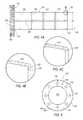
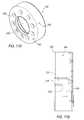
- FIGS. 1A-1Cillustrate a prior art surgical access system.
- FIG. 2is a perspective cross-sectional view of an exemplary arrangement of a surgical access assembly.
- FIG. 3is a perspective view of an outer sheath of the surgical access assembly of FIG. 2 .
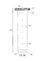
- FIG. 4Ais a side elevational view of the outer sheath of FIG. 3 .
- FIG. 4Bis an enlarged cross-sectional view of a portion of the distal end of the outer sheath of FIG. 4A .
- FIG. 4Cis an enlarged cross-sectional view of a portion of an alternative embodiment of the distal end of the outer sheath of FIG. 4A .
- FIG. 5is an end view of outer sheath of FIG. 3 .
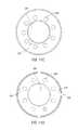
- FIG. 6Ais an elevational view of an alternative embodiment of an outer sheath.
- FIG. 6Bis an end view of the outer sheath of FIG. 6A .
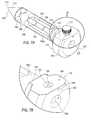
- FIG. 7Ais a perspective view of an obturator assembly of the surgical access assembly of FIG. 2 .
- FIG. 7Bis an enlarged view of an end face of the obturator assembly taken from area 7 B of FIG. 7A .
- FIG. 8Ais a top view of the obturator assembly of FIG. 7A .
- FIG. 8Bis an enlarged view of a distal end of the obturator assembly taken from area 8 B of FIG. 8A .
- FIG. 8Cis an alternative embodiment of the distal end of the obturator assembly taken from area 8 B of FIG. 8A .
- FIG. 8Dis an alternative embodiment of the distal end of the obturator assembly taken from area 8 B of FIG. 8A .
- FIG. 9Ais a side elevational view of the obturator assembly of FIG. 7A .
- FIG. 9Bis an enlarged view of a portion of the obturator assembly taken from area 9 B of FIG. 9A .
- FIG. 10is an end view of the obturator assembly of FIG. 7A .
- FIG. 11Ais a perspective view of an illuminating ring that operatively connects to an outer sheath of the surgical access assembly.
- FIG. 11Bis a side view of the illuminating ring of FIG. 11A .
- FIG. 11Cis a top view of the illuminating ring of FIG. 11A .
- FIG. 11Dis a bottom plan view of the illuminating ring of FIG. 11A .
- FIG. 11Eis a cross-sectional view of an exemplary arrangement of a lighting arrangement for the illuminating of FIG. 11A .
- FIG. 11Fis a plan view of a circuit board for use with the illuminating ring of 11 A.
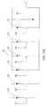
- FIG. 11Gis an exemplary electrical schematic for use with the illuminating ring of FIG. 11A .
- FIG. 12illustrates the illuminating ring of FIG. 11A assembled to an exemplary embodiment of the outer sheath.
- FIG. 13is a flow chart illustrating a process flow using the surgical access assembly.
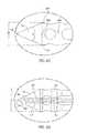
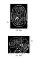
- FIG. 14A-14Bare images of a brain illustrating an area of interest, taken using an imaging modality.
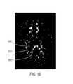
- FIG. 15is an image taken of the brain shown in FIGS. 14A-14B , illustrating various critical structures, such as fiber tracts and fascicles of the brain.
- FIG. 16Ais an alternative embodiment of an obturator with an imaging device operatively connected thereto.
- FIG. 16Bis a partially exploded view of an enlarged cross-sectional view of the proximal end of the obturator and post.
- FIG. 16Cis an alternative arrangement of a coil sensor for use with an obturator.
- FIG. 16Dis an end view of the coil sensor mounted on the post of FIG. 16C .
- FIG. 17Ais an elevational view of the surgical access system, while the obturator is being withdrawn from the outer sheath.
- FIG. 17Bis an elevational view of the surgical access system with the outer sheath in place within the brain.
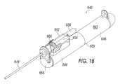
- FIG. 18is a perspective view of an exemplary surgical device used for cytoreduction.
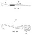
- FIG. 19Ais an elevational view of an exemplary manipulation member.
- FIG. 19Bis an elevational view of an alternative manipulation member.
- FIG. 20is a partial perspective view of an exemplary delivery sleeve that may be used with a surgical device.
- FIG. 21Ais an exemplary arrangement for a therapy delivery device.
- FIG. 21Bis an alternative arrangement of the therapy delivery device of FIG. 21A .
- Described hereinis surgical access assembly, various components for use in same, and a method of using the surgical access assembly.
- the components disclosed hereinprovide surgeons with an enhanced ability to minimize trauma to the patient, while providing efficient improved minimally invasive surgical techniques, such as, for example, during intracranial surgical techniques.
- surgical access assembly 100comprises a hollow outer sheath 102 and a selectively removable obturator 104 .
- obturator 104is configured with a length that is longer than a length of outer sheath 102 such that a distal end 106 of obturator 104 protrudes a predetermined distance from a distal end 108 outer sheath 102 , as will be discussed below in greater detail.
- Locking member 100is configured to operatively retain a separate navigation member 112 (shown in phantom) within obturator 104 , as will be discussed in greater detail below.
- a retaining member 114may be secured within a portion of obturator 104 to prevent locking member 110 from being completely disengaged from obturator 104 .
- Outer sheath 102is defined by distal end 108 and a proximal end 116 and includes a generally hollow body portion 118 and a grip portion 120 .
- grip portion 120is configured as a ring, as illustrated in the drawings. However, it is understood that grip portion 120 need not be configured as a ring. For ease of explanation, grip portion 120 will be referred to hereinafter as grip ring 120 .
- Grip ring 120is fixedly secured to body portion 118 at proximal end 116 .
- body portion 118is constructed of a clear biocompatible material that permits viewing of normal tissue, abnormal tissue, as well as critical structures that are disposed outside of body portion 118 when outer sheath 102 is disposed within such tissue.
- outer sheath 102is constructed of polycarbonate, though other biocompatible materials may be employed, including resins.
- an imaging mechanismmay be incorporated into outer sheath 102 that would permit visualization of tumors, vessels, fiber tracks, fascicles and even healthy tissue, in real-time.
- the imaging mechanismwill enable physiological functional imaging to provide information about the characteristics of the cortical fiber tracks to be visible, be visible, thereby enabling a user to separate and park such fibers on either side of outer sheath 102 rather than cutting, stretching and potentially damaging such fibers while gaining access to a desired location within the brain.
- the imaging mechanismmay also enable the surgeon to have real-time information about the fiber tract and fascicle location, after placement of outer sheath 104 , and during abnormality resection procedure therethrough. In addition to white matter tract imaging, mapping of the characteristics of the cerebral blood flow may be obtained.
- the imaging mechanismmay be an ultrasound probe incorporated into outer sheath 102 .
- outer sheath 102may be provided with one or more channels within the wall that defines outer sheath 102 that are configured with one or more small diameter ultrasound probes.
- a single ultrasound probe that is configured to be received within outer sheath 102may be provided.
- a low field MRI probemay be selectively placed in outer sheath 102 to provide enhanced imaging.
- a low field MRI imaging coilmay be molded into or bonded into outer sheath 102 .
- the probemay be an optical coherent tomography (OCT) imaging or spectroscopy.
- OCToptical coherent tomography
- Distal end 108 of outer sheath 102may be configured with a tapered portion 130 that extends towards a center axis A-A of outer sheath 102 to a distal edge 132 that surrounds an opening 134 in distal end 108 of outer sheath 102 .
- Tapered portion 130serves to ease the transition between outer sheath 102 and a distal tip portion 172 , without drag, trauma or coring of tissue from a diameter that defines a body portion 168 of obturator 104 to a diameter that defines body portion 118 of outer sheath 102 .
- distal end 108may be configured with a radius or other configuration so as to create a smooth/atraumatic transition of the brain tissue when surgical access assembly 100 is inserted into the brain.
- distal edge 132is configured so as to be non-sharpened and radiused.
- distal edge 132is configured as a 0.3 mm diameter radiused rim.
- Tapered portion 130 and radiused distal tip 132cooperates with obturator 104 to atraumatically move tissue, as well as various structures within the brain, including white matter, away from outer sheath 102 without cutting tissue or such structures.
- radiused distal tip 132cooperates with tapered portion 130 and obturator 104 to prevent bruising and damage to various tissue. More specifically, this configuration facilitates entry of outer sheath 102 into delicate tissue, but without cutting such delicate tissue. Insertion of surgical access assembly 100 will be explained in further detail below.
- Body portion 118may further be provided with a plurality of spaced apart indicators 136 .
- Indicators 136generally extend about the circumference of body portion 118 and each may further incorporate a secondary indicator 138 that visually illustrates a predetermined location on body portion 118 , as shown in FIG. 3 . While FIG. 3 illustrates four indicators 136 , it is understood that body portion 118 may be provided in a variety of lengths and that any number of indicators 136 may be provided.
- Body portion 118may also be provided with a longitudinal indicator 140 . More specifically, as best seen in FIG. 4A , longitudinal indicator 140 extends from proximal end 116 to distal end 108 .
- Indicators 136 , 138 and 140may be printed onto either an internal or external surface of body portion 118 with an imaging visible ink such as, for example ink containing fluro-deoxyglucose (FDG), Technicium 99, Gadolinium, titanium dust, barium sulfate, a combination of the above or other suitable imaging material.
- Indicators 136 and 138provide a reference point for the operator of system 100 , as structures may be visible through body portion 118 .
- Indicator 136 , 138 and 140may also be configured to be visible under MRI, CT, PET, or any other suitable imaging modality to enable easy identification of areas of interest.
- indicators 136 , 138 and/or 140may be etched or printed onto body portion 118 , either on the internal or external surface of body portion 118 .
- Grip ring 120is generally configured as a flange member 142 defined by an outer periphery 144 and an inner opening 146 .
- Inner opening 146may be sized to generally correspond to the diameter of a lumen 148 defined by body portion 118 .
- Outer periphery 144is sized to have a diameter that is larger than lumen 148 of body portion 26 .
- Flange member 142may further be provided with one or more small openings 150 that are disposed therein. In one exemplary arrangement, a plurality of small openings 150 are provided that are spaced generally equi-distantly about inner opening 146 . Small openings 150 will be described in further detail below.
- Outer periphery 144may further be provided with a textured surface 152 to provide for ease of gripping outer sheath 102 .
- textured surface 152comprises a plurality of alternating ridges 154 and grooves 156 .
- other textured surfacesmay be employed.
- Alignment feature 160is used to indicate the location of longitudinal indicator 140 when outer sheath 102 is positioned within the brain. Alignment feature 160 will be discussed below in greater detail.
- Outer sheath 202is similar to outer sheath 102 in that it is defined by a distal end 208 , a proximal end 216 and a body portion 218 .
- a distal edge 232is generally configured to be similar as distal tip 132 .
- a grip ring 220is fixedly secured to body portion 218 .
- Grip ring 220also includes a textured surface 252 .
- Grip ring 220further includes a locating member 262 .
- Locating member 262is configured to operatively connect an illumination ring (best seen in FIG. 11A ) 300 to outer sheath 102 .
- locating member 262extends outwardly from outer periphery 244 of grip ring 220 .
- Locating member 262may also serve as an alignment feature for indicating the location of longitudinal indicator 240 .
- a separate alignment feature 260may be provided.
- alignment feature 260is positioned adjacent locating member 262 .
- Body portion 218may also be provided with indicators 34 , 36 , and 38 to assist in locating outer sheath 202 in operation.
- body portion 218may be provided with indicators 264 that produce a signal void or minimal artifact under certain imaging modalities.
- indicators 264may be configured as small holes that are spaced apart at predetermined distances, as shown in FIG. 6A .
- indicators 264may be configured as non-through divots.
- indicators 264may be configured as a longitudinal groove (not shown) on either the internal or external surface of body portion 218 .
- Obturator 104is defined by distal end 106 , a proximal end 166 , a body portion 168 and a handle portion 170 .
- Distal end 106is configured with a generally conical shaped distal tip portion 172 that tapers to a tip member 174 to provide atraumatic dilation of tissue.
- tip portion 172tapers toward a closed tip member 174 so as to prevent coring of tissue as obturator 104 is inserted into the brain.
- surgical access assembly 100will be provided as part of a kit that may include multiple sized outer sheaths 102 and obturators 104 , to provide the surgeon with a choice of different diameter sizes and lengths so as to provide flexibility for accessing areas of interest within the brain.
- taper angle ⁇may be selectively adjusted.
- taper angle ⁇will need to be increased, as diameter D 1 increases.
- an exemplary angle ⁇may be 45.5° to provide effective atraumatic dilation, as well as a determinable distal tip 174 location.
- an exemplary angle ⁇ ′may be 52.8°.
- distal tip 174is configured to be radiused such that tip member 174 is rounded, and neither blunt, nor sharp. More specifically, tip member 174 is configured so as not to have any flat portions which during insertion can stretch or even tear the delicate tissues such as the vessels, fiber tracts and fascicles found in the brain. Further, because tip member 174 is closed, damage of such delicate tissues and fascicles are also avoided. In one exemplary embodiment, tip member 174 is configured with a 0.5 mm radius.
- tip member 174is designed to gently displace and move the tissue into which it is inserted; i.e., atraumatically dilate the tissue to allow for introduction in to an intra-fascilar and para-fascilar manner, as opposed to cutting tissue as surgical access assembly 100 is inserted into the tissue.
- Handle portion 170is positioned at proximal end 166 of obturator 104 . As best seen in FIGS. 7B, 8A and 9A , handle portion 170 comprises a stop member 176 and a grip member 178 . Stop member 176 is positioned distally of grip member 178 and, as best seen in FIG. 8A , is configured to have a width W 1 that is greater than a diameter D 1 of body portion 168 , as well as a diameter D 2 of outer sheath 102 (shown in FIG. 4A ). Grip member 178 is configured with a width W 2 that is greater than the width W 1 of stop member 176 , thereby providing a step-like configuration. Stop member 176 further defines an engagement surface 177 that is axially spaced from a distal surface 179 of grip member 178 .
- handle portion 170is configured with a generally planar surface 180 , as best seen in FIGS. 7A-7B and FIG. 10 .
- Planar surface 180is configured with a receiving aperture 182 that is configured to receive locking member 110 .
- receiving aperture 182is threaded.
- disposed within receiving aperture 182is an engagement opening 184 .
- Engagement opening 184is in communication with a channel 186 (seen in phantom in FIGS. 8A and 9A ) that extends at least partially thorough handle portion 170 .
- retaining member 114extends across a portion of receiving aperture 182 such that locking member 110 is prevented from being entirely withdrawn from receiving aperture 182 .
- locking member 110is illustrated as having threads that cooperate with corresponding internal threads in receiving aperture 182 .
- Retaining member 114is positioned within channel 186 so as to extend above the threads of locking member 110 such as locking member 110 is being removed from receiving aperture 182 , threads come into contact retaining member 114 , thereby preventing complete removal of locking member 110 from handle portion 170 .
- Access opening 188is formed through proximal end 166 .
- Access opening 188extends through handle portion 170 .
- access opening 188may be provided with an inwardly extending chamfer 189 that tapers toward access opening 188 .
- Chamfer 189provides a self-directing feature for inserting navigation member 112 into access opening 188 .
- Access opening 188is in communication with a first channel segment 191 that extends through handle portion 170 and into body portion 168 .
- obturator 104may further be configured to receive a viewing member 167 operatively connected thereto.
- conical tip portion 172may be configured with one or more viewing windows 169 that are oriented to be flush with the surface of conical tip portion 172 .
- Viewing windows 169are in communication with a viewing member channel 171 that may selectively receive a viewing member such as, for example, a fiber optic cable or an ultrasound probe.
- the viewing membermay be in addition to the use of navigation member, or in place thereof. The viewing member permits the surgeon to observe, in real-time (i.e., during insertion), surrounding tissue and eloquent tissue structures so as to minimize trauma during insertion.
- Body portion 168extends between distal end 106 and proximal end 166 .
- Body portion 168includes one or more elongated void areas 190 .
- Void areas 190serve to reduce weight of obturator 104 , thereby making obturator 104 easier to manipulate during surgical procedures.
- Void areas 190also facilitate sterilization of obturator 104 within body portion 168 of obturator 104 .
- void areas 190also provide venting, thereby preventing a vacuum from being generated as obturator 104 is being withdrawn from outer sheath 102 during operation.
- Void areas 190are separated by web portions 192 that extend axially through a portion of the length of body portion 168 .
- Disposed on web portions 192 of body portion 168are one or more indicators 194 .
- Indicators 194may include spaced apart hash marks (designated as 194 A) that cooperate with an imaging modality to provide information, in real-time, concerning the location of obturator 104 relative to various tissue, critical structures, and fascicles within the brain, while obturator 104 is positioned within tissue. Indicators 194 also assist with providing information to regarding the relative positions between obturator 104 and outer sheath 102 . Indicators 194 produce a signal void or minimal artifact under certain imaging modalities.
- Body portion 168may further include one or more cross webs 196 .
- Cross webs 196are oriented transverse to web portions 192 and connect web portions 192 together.
- body portion 168includes at least one cross web 196 that operatively defines the outer diameter D 2 of body portion 168 .
- Diameter D 2is sized to fit within lumen 148 of outer sheath 102 such that obturator 104 and outer sheath 102 may be selectively slid relative to one another.
- diameter D 2is also sized to minimize or even eliminate any gaps between an inner surface of outer sheath 102 and an outer surface of obturator 104 .
- cross webs 196 A, 196 B and 196 Care provided.
- a first cross web 196 Ais connected to distal tip portion 172
- second cross web 196 Bis spaced proximally from first cross web 196 A and separated by a void area 193 .
- Third cross web 196 Cis separated from second cross web 196 B by void areas 192 and is positioned distal from first stop member 176 of handle portion 170 .
- Cross webs 196serve to provide for structural integrity of obturator 104 , as well as improved rigidity.
- one or more of cross webs 196may further be provided with an annular compensating protuberance 197 to accommodate for slight manufacturing variations of the diameter of lumen 148 of outer sheath 102 .
- outer sheath 102may be a component that is molded from a resin, a process which may produce such slight manufacturing variations.
- Compensating protuburance 197extends slightly radially outwardly from an outer surface of obturator 104 and cooperates with lumen 148 of outer sheath 102 to create a friction fit between the outer surface of obturator 104 and lumen 148 , due to the slight flexibility of the resin of outer sheath 102 .
- Use of compensating protuberance 197thereby reducing the need for maintaining a high dimensional tolerance of outer sheath 102 in production.
- cross web 196 Bis provided with a second channel segment 198 (shown in phantom) that extends there through. Second channel segment 198 is axially aligned with first channel segment 191 and is configured to selectively receive navigation member 112 .
- disposed in first cross web 196 Ais an inwardly extending depression 199 , as best seen in FIG. 9B . Depression 199 is configured in such a manner so as to align a distal tip of navigation member 112 with distal end 108 of outer sheath 102 , when outer sheath 102 is assembled to obturator 104 .
- Illuminating ring 300is generally defined by a top surface portion 302 , a wall member 304 .
- a circuit board 306may also be provided.
- Top surface 302includes at least one access opening 308 therethrough that is configured to receive one or more surgical instruments, as will be described below in further detail.
- Additional small openings 309may be provided in top surface 302 .
- One or more of small openings 309are configured to be aligned with small openings 150 disposed on flange member 142 .
- Wall member 304extends from top surface 302 so as to create an open cavity 310 within illuminating ring 300 .
- An outer surface of wall member 304may be textured (not shown), similar to grip ring 120 .
- One or more light elements 312that are supported by a portion of illuminating ring 300 .
- lights 312are fixedly mounted to top surface 304 so as to face inwardly toward open cavity 310 , adjacent access opening 308 .
- Each light 312is electrically connected to a remote power source (not shown) by wires 314 .
- wires 314may be retained within channels formed in top surface 302 around access opening 308 .
- lights 312may be incorporated in a circuit board 306 .
- Circuit board 306is configured with an access opening 316 that may be aligned with access opening 308 formed in top surface 302 . Further, circuit board 306 is also sized to be positioned within open cavity 310 , and fixed thereto. In other words, in one arrangement, circuit board 306 is sized to have an outer diameter that is smaller than an inner diameter defined by wall member 304 .
- a wall opening 318may be formed through a portion of either top surface 302 or wall member 304 to provide access for wires 320 to electrically connect circuit board 306 to a power source. An example of wall opening 318 may be seen in FIGS. 11B, 11D, and 11F .
- Circuit board 306may be configured such that there is a constant output of light when illuminating ring 300 is turned on so that there is a steady state.
- circuit design 321is depicted in FIG. 11G for circuit board 306 .
- circuit design 321is configured to prevent flickering of lights 312 and/or prevent operation of less than all of the lights 312 during use of illuminating ring 300 . More specifically, circuit design 321 is configured such that if one light 312 burns out, or if batteries that supply power to circuit get low, illuminating ring 300 will simply shut off and a replacement battery pack (not shown) may be used.
- lights 312are LED lights, although other light devices may be utilized. LED lights do not contribute significantly to the weight of surgical access assembly 100 , and also dissipates a non-clinical significant amount of heat. Moreover, LED lights can emit different combinations of colors/frequencies of light that may be incorporated to illuminating ring 300 , to provide improved visualization of fluorescing dyes which allow for the differentiation of tissues.
- LED lightsalso allow for an endoscope to be used with surgical access assembly 100 , but without an accompanying fiber-optic light source.
- This arrangementsignificantly reduces a required overall outside diameter of the endoscope, which improves the working space within lumen 148 of outer sheath 102 . More specifically, lumen 148 of outer sheath 102 has more available working space, thereby providing increased simultaneous use of multiple instrumentation, as well as improved visualization.
- traditional endoscope devicesmust be attached to a supporting structure that is fixed to an introducer cannula, the weight of such an assembly tends to pull on the introducer cannula, in one direction. This action can compromise the placement of the introducer cannula during the procedure and/or cause trauma to brain tissue.
- illuminating ring 300to outer sheath, such potential disadvantages may be avoided.
- illuminating ring 300may be secured to grip ring 120 of outer sheath 102 in any suitable manner
- illuminating ring 300is provided with a selective locking arrangement to selectively fix illuminating ring 300 to grip ring 120 .
- wall member 304is provided with a locking channel 322 , best seen in FIG. 11B .
- Locking channel 322comprises wall opening 318 and that opens into a first channel segment 324 , and a second channel segment 326 that is in communication with first channel segment 324 .
- Wall opening 318extends from a bottom surface 328 of wall member 304 .
- Second channel segment 326is spaced upwardly from bottom surface 328 of wall member 304 and is oriented at an angle from first channel segment 324 .
- second channel segment 326is oriented 90° from first channel segment 324 .
- Locking channel 322cooperates with locating member 262 to selectively secure illuminating ring 300 to grip ring 120 . More specifically, illuminating ring 300 is pushed down over grip ring 120 with locating member 262 entering wall opening 318 . As illuminating ring 300 is pushed downwardly, locating member 262 travels through first channel segment 324 . Once locating member 262 contacts an terminal end 330 of first channel segment 324 , illuminating ring 300 is rotated relative to outer sheath 102 such that locating member 262 moves into second channel segment 326 , thereby selectively locking illuminating ring 300 to outer sheath 102 , as shown in FIG. 12 . Once connected, illuminating ring 300 thereby provides a hands-free light source to illuminate lumen 148 of outer sheath 102 .
- certain segments of outer sheath 102may be frosted so as to reflect light to increase visualization within outer sheath 102 .
- tapered portion 130may be frosted.
- the top of grip ring 120may also be frosted.
- process flow 400Operation of surgical access assembly will be described in connection with a process flow 400 illustrated in FIG. 13 .
- a patientwill first present with symptoms or deficits requiring evaluation.
- the start of process flow 400begins with a surgeon making a determination 402 of the cause of such neurological symptoms/deficits. Such a determination may be made through use of a variety of imaging modalities, including, but not limited to, MRI or CT imaging.
- the processthen proceeds to step 404 .
- step 402finds that a brain condition is found, such as a tumor or hematoma, an additional determination is required. More specifically, a location of the brain condition is determined in step 404 . If the imaging determines that an area of interest is located in the intra-axial/subcortical space, the process flow continues to step 406 . However, if a brain condition is located in other, more easily accessible areas of the brain, the process flow stops.
- FIGS. 14A and 14Billustrate examples of imaging results from an MRI. More specifically, an area of interest 500 , in this case a tumor, may be seen deep in the subcoritcal space.
- an additional imaging sequenceis employed to determine the location of eloquent structures such as vessels and fiber tracts and the associated fascicles so as to plan the safest access route to the area of interest.
- exemplary arrangements for accomplishing this stepinclude CT-Angiography and MRI with Diffusion Tensor Imaging (DTI) sequences.
- DTIallows for the determination of directionality as well as the magnitude of water diffusion along the communication “wiring” pathways called fiber tracts and fascicles.
- This kind of MRI imagingcan provide imaging to allow for the estimation of potential damage to nerve fibers that connect the areas of the brain which can be affected by a stroke, for example, to brain regions that are distant from it, and can also be used to visualize white matter fibers in the brain and can map (trace image) subtle changes in the white matter associated with diseases such as multiple sclerosis and epilepsy, as well as assessing diseases where the brain's wiring is abnormal, such as schizophrenia, as well as tumor involvement.
- DTTDiffuse Tensor Tractography
- DTTallows for noninvasive racking of neuronal fiber projections in a living human brain.
- White matter fiber trajectoriesare reconstructed throughout the brain by tracking the direction of fastest diffusion, which is assumed to correspond to the longitudinal axis of the tract.
- Diffusion tensor tractographyprovides insight into white matter integrity, fiber connectivity, surgical planning, and patients prognosis.
- FIG. 15an example of DTI imaging of the brain shown in FIGS. 14A and 14B is depicted.
- a map of fascicles and other vesselsare illustrated in FIG. 15 , including major vessels 502 that are shown spread around area of interest 500 .
- Such imagesprovide the surgeon with valuable information about potential avenues for access tracts to area of interest 500 .
- a plan for the operative trajectoryis developed. More specifically, imaging information is used to plan (either manually or with software) the access tract/pathway to achieve fiber tract involvement during access to the area of interest. In evaluating fiber tract involvement from a potential access tract/pathway, consideration of fiber tract importance may be based on an individual patient's occupational and personal needs and/or preference.
- step 410image data from the MRI/DTI and CT/CTA image sequence obtained during step 406 is input into an intraoperative navigation system.
- Intraoperative navigation systemsmay be used to provide direct visualization of area of interest 500 in real time, as surgical access system 100 is being positioned within the brain. The method then proceeds to step 412
- step 412requires that the appropriate sized surgical access assembly 100 is selected. First the appropriate size of a craniotomy must be determined. Further, the present disclosure contemplates that different diameter and length sizes of surgical access assembly 100 may be employed, the size depending on the particular location of area of interest 500 . Accordingly, step 412 requires that the surgeon select the appropriate length and diameter of surgical access system 100 to be used, based on the physical and location characteristics of the area of interest 500 . Once surgical access assembly 100 is selected, the process proceeds to step 414 .
- step 414the surgeon creates the craniotomy and Dural access incision. The process then proceeds to step 416 .
- step 416the obturator 104 is inserted into outer sheath 102 until grip ring 120 abuts first stop member 176 , as shown in, for example FIG. 2 .
- Navigation member 112is then operatively connected to obturator 104 .
- navigation member 112is configured as a probe (as shown in FIG. 2 ). In this configuration, navigation member 112 is inserted through access opening 188 of grip member 178 until a distal tip 417 of navigation member 112 is deposited into depression 199 (see FIG. 9B ). Depression 199 is formed so that distal tip 471 of navigation member 112 is positioned within the same plane as distal tip 132 of outer sheath 102 , when obturator 102 and outer sheath 104 are assembled together as shown in FIG. 2 . Locking member 110 may be tightened to fixedly retain navigation member 112 within obturator 102 .
- a portion of navigation member 112will extend proximally from grip member 178 and will be operatively connected to a navigation system that includes a screen that visually illustrates the information obtained from the imaging sequences, along with the trajectory of surgical access system 100 .
- a navigation systemthat includes a screen that visually illustrates the information obtained from the imaging sequences, along with the trajectory of surgical access system 100 .
- the software operating the navigation systemmay further be provided with an offset dimension that corresponds to a distance D 3 between distal tip 174 of obturator 104 and distal tip 132 of outer sheath.
- a dotted linemay appear on the navigation screen that indicates where distal tip 174 of obturator 104 is located, in real-time.
- Navigation member 112may further be provided with image guidance position indicators, such as an array of reflectors of the type use in connection with optical image guidance systems.
- image guidance position indicatorssuch as an array of reflectors of the type use in connection with optical image guidance systems.
- the infrared reflectors used with such a systemare mounted to a handle of a probe-like navigation member 112 in a customary triangular configuration calibrated to identify the tool to the image guidance system.
- imaging systemsare available, for example Medtronic Surgical Navigation Technologies (Denver, Colo.), Stryker (Kalamazoo, Mich.), and Radionics (Burlington Mass.).
- the positioning of the indicatorsis calibrated such that the image guidance system can project an image of the tool onto a display of images of the patient's brain, such as MRI images used to plan surgery.
- the image guidance systemcan project an image of the tool onto a display of images of the patient's brain, such as MRI images used to plan surgery.
- an RFID chipmay be embedded in obturator 104 that operatively communicates information to a navigation system or other surgical system about the specific attributes, such as, but not limited to, length and diameter. This information may be used to facilitate placement with the navigation system or other systems for information display or trajectory and location calculations during placement of obturator 104 .
- an alternative embodiment of an obturator 504may be used, wherein the obturator 504 is configured with a post 512 that is configured to operatively attach a navigation array.
- Post 512may be detachably or permanently connected to grip member 578 of obturator 104 .
- post 512is configured to be selectively detachable and may be used to capture a small coil 513 for MRI tracking of surgical access assembly 100 .
- a portion of post 512may be threaded and an access opening 588 formed in a proximal face of grip member 578 have be provided with corresponding threads (not shown) so as to affix post 512 to obturator 504 .
- Other manners of selectively affixing post 512 to obturator 504are also contemplated, including, but not limited to, a locking member 110 arrangement similar that shown in FIG. 2 .
- post 512need not be selectively detachable. Indeed, it is contemplated that post 512 may be permanently affixed to obturator 504 , in any suitable manner, whereby the navigation array may be secured to post 512 .
- obturator 504may be configured such that a post, which is an element of the array itself, may be attached.
- a coil sensor 513 ′may be configured to be disposed about an outer periphery of post 512 .
- coil sensor 513 ′is slid or otherwise mounted to post 512 such that when post 512 is operatively attached to obturator 504 coil sensor 513 ′ is captured between a portion of grip member 578 and a proximal end portion 514 .
- a connecting wire 516operatively attaches coil sensor 513 ′ to an image position console 518 .
- surgical access assembly 100is assembled and operatively connected to a navigational system, the process then proceeds to step 418 , in which surgical access assembly 100 is navigated to area of interest 500 .
- distal tip 178 of obturator 104is directed to a furthermost outer margin of area of interest 500 . More specifically, referring to FIG. 14B , for example, surgical access assembly 100 is directed along a trajectory T that extends through area of interest 500 to a location 501 that may positioned within the margins of area of interest 500 or even slightly beyond the margin.
- step 420navigation member 112 removed from or detached from surgical access assembly 100 .
- the processthen proceeds to step 422 .
- outer sheath 102is then operatively positioned with respect to area of interest 500 . More specifically, as shown in FIG. 17A , outer sheath 102 is decanted with respect to obturator 104 such that distal end 108 of outer sheath 102 is moved toward distal end 106 of obturator 104 , as indicated by arrow M. This action is accomplished by grasping grip ring 120 with one hand while maintaining obturator 104 stationary, such, for example, grasping grip member 178 with another hand.
- Grip ring 120may be gently rotated and/or swiveled with respect to a central axis of obturator 104 to enable outer sheath 102 to be moved distally with respect to obturator 104 .
- First stop member 176aids in gripping and manipulating outer sheath 102 , in that a gap 423 (see FIG. 2 ) is created between end surface 158 and a distal end surface of grip member 178 .
- Outer sheath 102is decanted until grip ring 120 aligns with indicator 194 A (see FIG. 7A ).
- Indicator 194 Ais spaced from first stop member 176 a distance that generally corresponds to the length of distal tip portion 172 of obturator 104 .
- outer sheath 102is aligned tip member 174 of obturator 104 . Moreover, outer sheath 102 is positioned within area of interest 500 . The process then proceeds to step 424 .
- step 424once outer sheath 102 is appropriately positioned, obturator 104 is then removed from outer sheath 102 , as shown in FIG. 17B . More specifically, outer sheath 102 is maintained to be relatively stationary at area of interest 500 , and obturator 104 is moved in a proximal direction until fully removed from outer sheath 102 . This action results in outer sheath 102 forming a pathway to area of interest 500 . The process then proceeds to step 426 .
- outer sheath 102is then secured in place so as to prevent cranial pressure from pushing outer sheath 102 out of the brain tissue.
- a securing membermay be utilized with small openings 150 on grip ring 120 to temporarily secure outer sheath 102 .
- small openings 309 in illuminating ring 300align with small openings 150 of grip ring.
- securing membersmay also be utilized with small openings 309 .
- the securing membermay be secured so as to permit a limited degree of movement, as will be discussed below, so as to result in a floating system that permits selective repositioning. Suitable securing members include, but are not limited to, bridle sutures, flexible bands with retaining hooks, or even repositionable retractor arms.
- debulking area of interest 500may be conducted.
- a patientis given medication, such as, for example, Mannitol, before an intracranial operation to reduce intracranial pressure (ICP) of the brain prior to the surgery.
- ICPintracranial pressure
- the present inventorshave found that it may be advantageous to omit or minimize the use of medication for reducing ICP.
- the target tissuemay have a tendency to flow into, and present itself into the open distal end 108 of outer sheath 102 , due to the cranial pressure.
- Area of interest 500may actually move into outer sheath 102 on its own, thereby assisting in the delivery and minimizing manipulation required of outer sheath 102 during the process.
- outer sheath 102may have an inner diameter up to approximately 20 mm, to allow multiple instruments, such as graspers, dissectors, scissors, cautery and suction instruments to be inserted through outer sheath 102 to perform surgery.
- Surgical cutting device 640includes a handpiece 642 and a cutting element that includes an outer cannula 644 and an inner cannula (not shown).
- handpiece 642is configured with a generally cylindrical shape.
- Handpiece 642may be sized and shaped to be grasped with a single hand Handpiece 642 also includes a lower housing 650 comprising a proximal section 646 and a distal section 648 .
- a front housing section 655may be connected to a cam housing positioned in distal section 648 .
- An upper housing 652is also provided.
- the cutting elementis mounted to upper housing 652 and may be fluidly connected to a tissue collector 658 .
- tissue collector 658may be operatively connected directly to upper housing 652 .
- tissue collector 658may be remotely connected to the cutting element by appropriate tubing.
- a vacuum line(not shown) may be connected to a proximal end of tissue collector 658 to direct tissue into the cutting element, as well as to deliver severed tissue to tissue collector 658 .
- a rotation dial 660 for selectively rotating the outer cannula 644 with respect to handpiece 642is also mounted to upper housing 652 , to provide controlled cutting action.
- surgical device 640is advantageous in that space is limited to effectuate tissue debulking, such that use of traditional surgical scissors may be challenging, especially when other instruments are inserted into outer sheath 102 simultaneously. Moreover, fibrosity of a tumor may present challenges for the use traditional suction debulking devices.
- Traditional graspersoperate by tearing tissue of interest. However, the tearing action may become problematic if vessels or fascicles are too close to the tissue being torn in that such vessels or fascicles may also be torn.
- step 428as area of interest 500 is cytoreductively debulked, it may become necessary to reposition or move outer sheath 102 . If repositioning is necessary, the process moves to step 432 .
- manipulation membersmay be provided. Examples of manipulation members 700 and 700 ′ are illustrated in FIGS. 19A-19B .
- Manipulation member 700comprises a handle member 702 that supports an armature 704 , and a hook element 706 that extends from armature 704 . Hook element 706 is sized to fit within small openings 150 and 309 disposed within grip ring 120 and illuminating ring 300 , respectively.
- hook element 706is engaged with a small opening 150 / 309 and handle member 702 is used to gently push or pull outer sheath 102 . Because outer sheath 102 is only loosely secured, outer sheath 102 may be selectively moved slightly for improved visualization or to access tissue. After outer sheath 102 has been repositioned, or if repositioning of outer sheath 102 is not necessary, the process moves to step 434 , and cytoreduction of area of interest 500 continues.
- manipulation member 700 ′may be secured to a flexible holder member 710 .
- Manipulation member 700 ′comprises an armature 712 that carries a hook element 714 and an engagement portion 716 .
- Engagement portion 716operatively engages holder member 710 so as to fixedly secure manipulation member 700 ′ to holder member 710 , thereby freeing a surgeon's hand, once outer sheath 102 is positioned. It is understood that multiple manipulation members 700 / 700 ′ may be utilized to permit a surgeon to selectively push or pull outer sheath 102 .
- Outer sheath 102is configured such that multiple instruments may be inserted simultaneously therewithin, thereby increasing the speed and safety of surgical procedures.
- an endoscopemay be partially inserted and held to one side of outer sheath 102 , to provide an image of area of interest 500 to a monitor, while a surgical instrument, such as surgical instrument 640 is also inserted within outer sheath 102 .
- Illuminating ring 300may also be used, with the endoscope and the surgical instrument being inserted through access opening 308 that aligns with opening 146 of grip ring 120 .
- illuminating ring 300provides the necessary light for outer sheath 102 , a relatively small diameter endoscope may be use, thereby increasing the available space within outer sheath 102 for other surgical instruments.
- the surgeonmay have both a surgical instrument and a cautery instrument simultaneously inserted into outer sheath 102 , thereby permitting the surgeon to cauterized vessels that are encountered during the procedure.
- fluorescing dyemay be introduced into the patient, either before surgery or during the surgery.
- One such dyeis Gliolan (5-Aminolevulinic Acid), however other suitable dyes may also be used.
- the fluorescing dyemay be introduced by any suitable methods, including, but not limited to, injecting the patient with the dye, providing the dye orally to the patient prior to surgery, or even injecting the dye in situ through outer sheath 102 .
- the dyeis configured to bond to proteins of abnormal cells such that the cells are visually distinguishable from healthy cells. With this visual indication of healthy vs. abnormal tissue, the surgical instrument may be more efficiently used to resect abnormal tissue.
- light delivered through outer sheath 102has a predetermined wavelength that is configured to interact with the dye to illuminate or fluoresce abnormal tissue.
- illumination cap 300may be provided with LED lights of a preselected wavelength that operatively interacts with a preselected dye to illuminate abnormal tissue and assist with differentiating healthy tissue from diseased tissue.
- a light probe or fiber optic bundlemay be inserted into outer sheath 102 to assist with differentiation between healthy tissue and abnormal tissue.
- the probe/bundleis simply inserted into outer sheath 102 as a separate element, along with a surgical device.
- the probe/bundleis operatively connected to a console such that the reflected light is delivered to the console.
- a sensor in the consolei.e., the sensor is remotely located from the point of detection, receives the reflected light to trigger a signal to the user based on predetermined parameters. In other words, the natural florescence of the tissue is then reflected back to the console to inform the user whether or not the tissue is diseased or abnormal.
- the surgical devicemay be further provided with a delivery sleeve 800 that mounts to surgical device 640 , and example of which may be found in FIG. 20 .
- a delivery sleeve 800that mounts to surgical device 640 , and example of which may be found in FIG. 20 .
- Various embodiments of delivery sleeve 800may be found in co-pending, and co-owned with the assignee of the present application, U.S. patent application Ser. No. 13/269,339, the contents of which are incorporated by reference in its entirety. As may be seen in FIG.
- delivery sleeve 800generally includes at least two lumens, a first lumen 802 which is configured to receive outer cannula 644 of surgical device 640 , and a second lumen 804 which is configured to receive an optical device, such as a light probe or a fiber optic bundle (not shown).
- an optical devicesuch as a light probe or a fiber optic bundle (not shown).
- the surgeoncan simultaneously differentiate between abnormal and healthy tissue, and resect tissue, all with by just holding the surgical device 640 .
- the surgeonmay also choose to utilize a separate cautery device within outer sheath 102 to permit cauterization of any vessels during the resection, in real time, and without requiring removal of the surgical device 640 .
- outer sheath 102may be directly positioned at area of interest 500 in such a manner as to avoid unnecessary damage to critical structures, and because surgical device 640 may be placed directly at the sight of area of interest, utilizing surgical access system 100 provides the ability to resect most of an area of interest 500 , such a tumor.
- a tumoris resected and removed, the less therapy is required for treatment. In other words, the more diseased tissue there is resected, the less diseased tissue there is to destroy.
- step 436a decision is made to either remove outer sheath 102 or to leave outer sheath 102 in position. More specifically, for some therapy applications, removal of outer sheath 102 may be more effective than leaving outer sheath in place to deliver the therapy. If the decision is made to remove outer sheath 102 , after removal of outer sheath 102 , the process 400 proceeds to step 438 .
- a delivery devicemay be inserted into the corridor to deliver irrigation to the surgical site.
- a syringemay be inserted into the corridor to deliver an irrigating fluid, such as saline directly to the surgical site.
- a drainage catheter(which is configured with a plurality of small openings at its distal end) is delivered into the corridor such that the distal end of the catheter is placed at or adjacent the surgical site.
- Irrigating fluidis then introduced into the proximal end (such, as for example, by operatively attaching a syringe barrel to the proximal end), to deliver the irrigating fluid to the surgical site.
- the irrigating fluidflushes out debris and assists in the brain tissue's natural tendency to close back in on itself.
- outer sheath 102may be necessary to aid in the delivery and/or placement of such therapy, as will be explained in further detail below. Accordingly, if the decision in step 436 is made to keep outer sheath 102 in place after completion of cytoreduction, the process 400 proceeds to step 442 .
- step 442area of interest/surgical site 500 is irrigated to again remove any debris from the area. Irrigation may be performed in the same manner as discussed in step 438 , except through outer sheath 102 . Once irrigation is complete, the process proceeds to step 444 .
- a therapyis delivered to area of interest 500 .
- intraoperative radiotherapyIORT
- an implantable therapymay be applied to area of interest 500 .
- an implantable therapyinclude: bioabsorbable radiation pellets, wafers or mesh, such as, for example, those manufactured by Nano-Rad LLC.
- Other examplesinclude, but are not limited to, titanium capsules or seeds with radiation contents, bioabsorbable gels or foams that contain radioactive, chemotherapy or immunotherapy agents.
- a balloon cathetermay be used to perform brachytherapy following the removal of diseased tissue at area of interest 500 .
- a balloon cathetermay be inserted through outer sheath 102 and delivered to area of interest, and then the balloon catheter may be inserted with a predetermined amount of radioactive solution followed by the delivery of radiation to the surrounding tissues.
- a commercially available catheter that may be usedincludes the GliaSite balloon catheter, with an Iotrex radioactive solution. Use of a balloon catheter may provide a more targeted delivery of liquid radiation, thereby reducing impact on brain tissues surrounding the diseased tissue.
- an electron beam driven X-ray sourcemay be provided.
- One such exemplary configurationis the Zeiss INTRABEAM®.
- the electronsare generated and accelerated in a main unit and travel via an electron beam drift tube which is surrounded by a conical applicator sheath such that its tip lies at an epicenter of an applicator sphere to provide a point source of low energy X-rays at the tip.
- a nearly isotropic field of low energyis emitted.
- the applicator sheathis inserted through outer sheath 102 and into the surgical cavity at area of interest 500 .
- An intraoperative ultrasoundmay be performed to determine the distance of the applicator surface to the skin, to avoid significant skin doses.
- the applicator sheathmay be secured into place by the surgeon using subcutaneous sutures around the neck of the sphere, similar to that described above in connection with outer sheath 102 .
- a photodynamic therapymay be used, whereby a predetermined chemical composition may provided to the patient and the chemical composition may be selectively activated by a predetermine wavelength, thereby achieving a therapeutic reaction.
- illuminating ring 300may be turned on to achieve the therapeutic reaction.
- a light sourcesuch as, for example, a fiber optic bundle, may be directed through outer sheath 102 , either directly through outer sheath 102 or through delivery sleeve 800 .
- external beam high frequency ultrasound or interstitial high frequency ultrasoundmay also be delivered through outer sheath and directly to area of interest 500 .
- an implantable delivery device 900 / 900 ′may be provided.
- Implantable delivery device 900 / 900 ′includes a neck portion 902 that is connected to a body portion 904 / 904 ′. Both neck portion 902 and body portion 904 / 904 ′ may be constructed of a relatively soft and flexible material.
- Body portion 904 / 904 ′defines a reservoir for holding a therapeutic agent therein.
- a proximal end 905 of neck portion 902is largely closed, with access to an interior of implantable delivery device 900 / 900 ′ being providing by a luer port 906 .
- therapy agentsare introduced into delivery device 900 / 900 ′ through luer port 906 .
- a sealing flange 908may further be provided, that operatively connects to neck portion 902 to assist in holding implantable delivery device 900 / 900 ′ in place within the brain.
- body portion 904may be provided with at least one small opening 910 .
- a plurality of small openings 910are provided, and such openings may be spaced equi-distance from one another about the periphery of body portion 904 .
- Small openings 910are configured to permit the therapy agent that is introduced through luer port 906 to weep out of the reservoir formed by body portion 904 at a controlled rate to increase effectiveness.
- body portion 900may be configured as a permeable membrane that permits slow and controlled passage of therapy from the reservoir to the brain tissue 1000 .
- body portion 904 ′may be provided with flexible finger-like projections 912 .
- projections 912are spaced equi-distance from one another about the periphery of body portion 904 ′.
- Projections 912extend outwardly from an outer periphery of body portion 904 ′ and may be formed with channels that provide communication between the reservoir and small openings 914 configured at distal tips 916 of projections 912 .
- Openings 914are configured to permit the therapy agent that is introduced through luer port 906 to weep out of the reservoir. Projections 914 assist in frictionally retaining delivery device 900 ′ at a target site.
- delivery device 900 / 900 ′is inserted at area of interest 500 through outer sheath 102 .
- outer sheath 102is removed, and sealing flange 908 is operatively connected to neck portion 902 such that luer port 906 is accessible.
- Sealing flange 908is configured to extend over the periphery of the surgical access opening that was formed through the skull 1002 , thereby providing protection for the exposed brain tissue 1000 .
- the therapeutic agentmay be supplied to the reservoir formed by body portion 904 / 904 ′ either before deliver device 900 / 900 ′ is positioned at area of interest 500 , or after sealing flange 908 is in place.
- Sealing flange 908 , as well as body portion 904 / 904 ′ and neck portion 902may be configured with flexible material to allow for sealing against the dura and bone of the brain.
- a transfer materialmay be delivered through outer sheath 102 , similar to a foam that is configured to conform to the cytoreducted area of interest 500 .
- the foamwill allow continuous contact with the therapy agent that weeps through body portion 904 / 904 ′ to provide a controlled dosage of therapy to area of interest 500 .
- step 446the instruments used for surgery and/or therapy are removed from outer sheath 102 .
- brain tissuewill fill the void formed by removing area of interest 500 so that healthy brain tissue underlying the now removed target tissue is adjacent the end of outer sheath 102 .
- Outer sheath 102is then gently removed and the brain tissue will naturally fill and reclaim the space formerly occupied by the abnormality and outer cannula 102 , aided by the irrigation of area of interest 500 .
- implanted therapiessuch as, for example, bioabsorbable radiation pellets, wafers or mesh
- implanted therapieswill be held in place at area of interest 500 to provide effective treatment. While this process may take several minutes, it is relatively atraumatic.
- outer sheath 102Once outer sheath 102 has been removed, the process continues to step 448 , whereby the dura, skull and scalp are then closed in a known manner and the process ends.
- full reclaiming of the spaceis delayed due to the implant until implant is explanted or absorbed.
- surgical access system 100will be provided as part of a kit. More specifically, it is contemplated that a set of multiple obturators 104 may be provided that have different lengths and/or diameters. The set may be provided in a container that is configured be sterilized, with obturators 104 secured therein. It is also contemplated that a set of manipulation tools 700 / 700 ′ may also be provided with the kit, and that manipulation tools 700 / 700 ′ may be positioned within the container for selective sterilization.
- Outer sheath 102may be provided with the kit, in various lengths and diameters that correspond to the lengths and diameters of obturators 104 provided in the kit. However, in one exemplary arrangement, outer sheaths 104 are provided separately as single use devices, in sterilized pouches.
Landscapes
- Health & Medical Sciences (AREA)
- Life Sciences & Earth Sciences (AREA)
- Surgery (AREA)
- Heart & Thoracic Surgery (AREA)
- Public Health (AREA)
- Animal Behavior & Ethology (AREA)
- Biomedical Technology (AREA)
- Veterinary Medicine (AREA)
- Engineering & Computer Science (AREA)
- General Health & Medical Sciences (AREA)
- Medical Informatics (AREA)
- Molecular Biology (AREA)
- Nuclear Medicine, Radiotherapy & Molecular Imaging (AREA)
- Pathology (AREA)
- Orthopedic Medicine & Surgery (AREA)
- Pulmonology (AREA)
- Anesthesiology (AREA)
- Hematology (AREA)
- Surgical Instruments (AREA)
Abstract
Description
Claims (29)
Priority Applications (30)
| Application Number | Priority Date | Filing Date | Title |
|---|---|---|---|
| US13/280,015US9770261B2 (en) | 2004-10-28 | 2011-10-24 | Surgical access assembly and method of using same |
| US13/444,722US9579121B2 (en) | 2004-10-28 | 2012-04-11 | Holding arrangement for a surgical access system |
| US13/444,713US9186175B2 (en) | 2004-10-28 | 2012-04-11 | Surgical access assembly and method of using same |
| US13/444,732US9265523B2 (en) | 2011-10-24 | 2012-04-11 | Surgical access system with navigation element and method of using same |
| US13/474,433US20120289816A1 (en) | 2004-10-28 | 2012-05-17 | Surgical access assembly and method of using same |
| CA2844755ACA2844755C (en) | 2004-10-28 | 2012-10-24 | Surgical access system |
| EP12816541.2AEP2770924B1 (en) | 2004-10-28 | 2012-10-24 | Surgical access system |
| CA3150112ACA3150112A1 (en) | 2011-10-24 | 2012-10-24 | Surgical access system |
| BR112014009641ABR112014009641A2 (en) | 2004-10-28 | 2012-10-24 | mounting and surgical access system |
| AU2012329006AAU2012329006B2 (en) | 2004-10-28 | 2012-10-24 | Surgical access system |
| JP2014537374AJP6108412B2 (en) | 2004-10-28 | 2012-10-24 | Surgical access system |
| PCT/US2012/061568WO2013063027A1 (en) | 2004-10-28 | 2012-10-24 | Surgical access system |
| CA3010024ACA3010024C (en) | 2011-10-24 | 2012-10-24 | Surgical access system |
| KR1020147006693AKR20140089509A (en) | 2004-10-28 | 2012-10-24 | Surgical access system |
| US13/786,186US9161820B2 (en) | 2004-10-28 | 2013-03-05 | Surgical access assembly and method of using same |
| US13/786,062US9387010B2 (en) | 2004-10-28 | 2013-03-05 | Surgical access assembly and method of using same |
| US14/847,863US10143366B2 (en) | 2004-10-28 | 2015-09-08 | Surgical access assembly and method of using same |
| US14/877,438US9622777B2 (en) | 2004-10-28 | 2015-10-07 | Surgical access assembly and method of using same |
| US14/996,847US10307183B2 (en) | 2011-10-24 | 2016-01-15 | Surgical access system with navigation element and method of using same |
| US15/207,265US10449340B2 (en) | 2004-10-28 | 2016-07-11 | Surgical access assembly and method of using same |
| US15/684,712US11284917B2 (en) | 2011-10-24 | 2017-08-23 | Surgical access assembly and method of using same |
| AU2018203807AAU2018203807B2 (en) | 2004-10-28 | 2018-05-30 | Surgical access system |
| US16/102,416US11464539B2 (en) | 2004-10-28 | 2018-08-13 | Surgical access assembly and method of using same |
| US16/208,085US11412923B2 (en) | 2004-10-28 | 2018-12-03 | Surgical access assembly and method of using same |
| US16/387,901US20190239923A1 (en) | 2011-10-24 | 2019-04-18 | Surgical access system with navigation element and method of using same |
| US17/115,472US11864793B2 (en) | 2004-10-28 | 2020-12-08 | Surgical access assembly and method of using same |
| US17/220,983US11969187B2 (en) | 2004-10-28 | 2021-04-02 | Surgical access assembly and method of using same |
| US17/888,196US12376741B2 (en) | 2004-10-28 | 2022-08-15 | Surgical access assembly and method of using same |
| US18/528,121US20240099740A1 (en) | 2004-10-28 | 2023-12-04 | Surgical access assembly and method of using same |
| US18/649,260US20240277373A1 (en) | 2004-10-28 | 2024-04-29 | Surgical access assembly and method of using same |
Applications Claiming Priority (4)
| Application Number | Priority Date | Filing Date | Title |
|---|---|---|---|
| US62309404P | 2004-10-28 | 2004-10-28 | |
| PCT/US2005/039185WO2006050225A2 (en) | 2004-10-28 | 2005-10-28 | Apparatus and methods for performing brain surgery |
| US66566607A | 2007-04-18 | 2007-04-18 | |
| US13/280,015US9770261B2 (en) | 2004-10-28 | 2011-10-24 | Surgical access assembly and method of using same |
Related Parent Applications (4)
| Application Number | Title | Priority Date | Filing Date |
|---|---|---|---|
| US11/665,666Continuation-In-PartUS20080109026A1 (en) | 2004-10-28 | 2005-10-28 | Apparatus and Methods for Performing Brain Surgery |
| PCT/US2005/039185Continuation-In-PartWO2006050225A2 (en) | 2004-10-28 | 2005-10-28 | Apparatus and methods for performing brain surgery |
| US66566607AContinuation-In-Part | 2004-10-28 | 2007-04-18 | |
| US13/444,732Continuation-In-PartUS9265523B2 (en) | 2004-10-28 | 2012-04-11 | Surgical access system with navigation element and method of using same |
Related Child Applications (6)
| Application Number | Title | Priority Date | Filing Date |
|---|---|---|---|
| US13/444,722Continuation-In-PartUS9579121B2 (en) | 2004-10-28 | 2012-04-11 | Holding arrangement for a surgical access system |
| US13/444,732Continuation-In-PartUS9265523B2 (en) | 2004-10-28 | 2012-04-11 | Surgical access system with navigation element and method of using same |
| US13/444,713Continuation-In-PartUS9186175B2 (en) | 2004-10-28 | 2012-04-11 | Surgical access assembly and method of using same |
| US13/786,062Continuation-In-PartUS9387010B2 (en) | 2004-10-28 | 2013-03-05 | Surgical access assembly and method of using same |
| US13/786,186Continuation-In-PartUS9161820B2 (en) | 2004-10-28 | 2013-03-05 | Surgical access assembly and method of using same |
| US15/684,712ContinuationUS11284917B2 (en) | 2011-10-24 | 2017-08-23 | Surgical access assembly and method of using same |
Publications (2)
| Publication Number | Publication Date |
|---|---|
| US20120071748A1 US20120071748A1 (en) | 2012-03-22 |
| US9770261B2true US9770261B2 (en) | 2017-09-26 |
Family
ID=60675782
Family Applications (2)
| Application Number | Title | Priority Date | Filing Date |
|---|---|---|---|
| US13/280,015Active2026-02-01US9770261B2 (en) | 2004-10-28 | 2011-10-24 | Surgical access assembly and method of using same |
| US15/684,712Active2033-04-01US11284917B2 (en) | 2011-10-24 | 2017-08-23 | Surgical access assembly and method of using same |
Family Applications After (1)
| Application Number | Title | Priority Date | Filing Date |
|---|---|---|---|
| US15/684,712Active2033-04-01US11284917B2 (en) | 2011-10-24 | 2017-08-23 | Surgical access assembly and method of using same |
Country Status (1)
| Country | Link |
|---|---|
| US (2) | US9770261B2 (en) |
Cited By (3)
| Publication number | Priority date | Publication date | Assignee | Title |
|---|---|---|---|---|
| EP3804638A2 (en) | 2019-10-11 | 2021-04-14 | Critical Innovations, LLC | Percutaneous access pathway system |
| US11707294B2 (en) | 2018-02-15 | 2023-07-25 | Minnetronix Neuro, Inc. | Medical device for accessing the central nervous system |
| US11974775B2 (en) | 2020-01-22 | 2024-05-07 | Minnetronix Neuro, Inc. | Medical device for accessing the central nervous system |
Families Citing this family (61)
| Publication number | Priority date | Publication date | Assignee | Title |
|---|---|---|---|---|
| US9770261B2 (en) | 2004-10-28 | 2017-09-26 | Nico Corporation | Surgical access assembly and method of using same |
| US9265523B2 (en) | 2011-10-24 | 2016-02-23 | Nico Corporation | Surgical access system with navigation element and method of using same |
| US9387010B2 (en) | 2004-10-28 | 2016-07-12 | Nico Corporation | Surgical access assembly and method of using same |
| US9216015B2 (en) | 2004-10-28 | 2015-12-22 | Vycor Medical, Inc. | Apparatus and methods for performing brain surgery |
| US9186175B2 (en)* | 2004-10-28 | 2015-11-17 | Nico Corporation | Surgical access assembly and method of using same |
| US9161820B2 (en) | 2004-10-28 | 2015-10-20 | Nico Corporation | Surgical access assembly and method of using same |
| US20060287583A1 (en)* | 2005-06-17 | 2006-12-21 | Pool Cover Corporation | Surgical access instruments for use with delicate tissues |
| US10080578B2 (en)* | 2008-12-16 | 2018-09-25 | Nico Corporation | Tissue removal device with adjustable delivery sleeve for neurosurgical and spinal surgery applications |
| US12137873B2 (en) | 2009-06-18 | 2024-11-12 | Endochoice, Inc. | Compact multi-viewing element endoscope system |
| US9706903B2 (en) | 2009-06-18 | 2017-07-18 | Endochoice, Inc. | Multiple viewing elements endoscope system with modular imaging units |
| US9101287B2 (en) | 2011-03-07 | 2015-08-11 | Endochoice Innovation Center Ltd. | Multi camera endoscope assembly having multiple working channels |
| US8926502B2 (en) | 2011-03-07 | 2015-01-06 | Endochoice, Inc. | Multi camera endoscope having a side service channel |
| US9642513B2 (en) | 2009-06-18 | 2017-05-09 | Endochoice Inc. | Compact multi-viewing element endoscope system |
| US9713417B2 (en) | 2009-06-18 | 2017-07-25 | Endochoice, Inc. | Image capture assembly for use in a multi-viewing elements endoscope |
| US11278190B2 (en) | 2009-06-18 | 2022-03-22 | Endochoice, Inc. | Multi-viewing element endoscope |
| US10165929B2 (en) | 2009-06-18 | 2019-01-01 | Endochoice, Inc. | Compact multi-viewing element endoscope system |
| US9901244B2 (en) | 2009-06-18 | 2018-02-27 | Endochoice, Inc. | Circuit board assembly of a multiple viewing elements endoscope |
| US11864734B2 (en) | 2009-06-18 | 2024-01-09 | Endochoice, Inc. | Multi-camera endoscope |
| US9101268B2 (en) | 2009-06-18 | 2015-08-11 | Endochoice Innovation Center Ltd. | Multi-camera endoscope |
| US9492063B2 (en) | 2009-06-18 | 2016-11-15 | Endochoice Innovation Center Ltd. | Multi-viewing element endoscope |
| US11547275B2 (en) | 2009-06-18 | 2023-01-10 | Endochoice, Inc. | Compact multi-viewing element endoscope system |
| WO2010146587A1 (en) | 2009-06-18 | 2010-12-23 | Peer Medical Ltd. | Multi-camera endoscope |
| US9402533B2 (en) | 2011-03-07 | 2016-08-02 | Endochoice Innovation Center Ltd. | Endoscope circuit board assembly |
| US9872609B2 (en) | 2009-06-18 | 2018-01-23 | Endochoice Innovation Center Ltd. | Multi-camera endoscope |
| US12220105B2 (en) | 2010-06-16 | 2025-02-11 | Endochoice, Inc. | Circuit board assembly of a multiple viewing elements endoscope |
| US9560953B2 (en) | 2010-09-20 | 2017-02-07 | Endochoice, Inc. | Operational interface in a multi-viewing element endoscope |
| EP2618718B1 (en) | 2010-09-20 | 2020-04-15 | EndoChoice Innovation Center Ltd. | Multi-camera endoscope having fluid channels |
| CN103403605A (en) | 2010-10-28 | 2013-11-20 | 恩多巧爱思创新中心有限公司 | Optical systems for multi-sensor endoscopes |
| US12204087B2 (en) | 2010-10-28 | 2025-01-21 | Endochoice, Inc. | Optical systems for multi-sensor endoscopes |
| US9320419B2 (en) | 2010-12-09 | 2016-04-26 | Endochoice Innovation Center Ltd. | Fluid channeling component of a multi-camera endoscope |
| US11889986B2 (en) | 2010-12-09 | 2024-02-06 | Endochoice, Inc. | Flexible electronic circuit board for a multi-camera endoscope |
| CN107361721B (en) | 2010-12-09 | 2019-06-18 | 恩多巧爱思创新中心有限公司 | Flexible electronic circuit boards for multi-camera endoscopes |
| EP2672878B1 (en) | 2011-02-07 | 2017-11-22 | Endochoice Innovation Center Ltd. | Multi-element cover for a multi-camera endoscope |
| JP5265823B1 (en)* | 2011-10-27 | 2013-08-14 | オリンパスメディカルシステムズ株式会社 | Ultrasonic observation equipment |
| CA2798716A1 (en) | 2011-12-13 | 2013-06-13 | Peermedical Ltd. | Removable tip endoscope |
| EP2604172B1 (en) | 2011-12-13 | 2015-08-12 | EndoChoice Innovation Center Ltd. | Rotatable connector for an endoscope |
| US9757147B2 (en)* | 2012-04-11 | 2017-09-12 | Nico Corporation | Surgical access system with navigation element and method of using same |
| US9560954B2 (en) | 2012-07-24 | 2017-02-07 | Endochoice, Inc. | Connector for use with endoscope |
| US10433763B2 (en) | 2013-03-15 | 2019-10-08 | Synaptive Medical (Barbados) Inc. | Systems and methods for navigation and simulation of minimally invasive therapy |
| US9600138B2 (en) | 2013-03-15 | 2017-03-21 | Synaptive Medical (Barbados) Inc. | Planning, navigation and simulation systems and methods for minimally invasive therapy |
| CN105050527B (en) | 2013-03-15 | 2018-03-27 | 圣纳普医疗(巴巴多斯)公司 | Intelligent positioning system and method therefor |
| CA2902592C (en) | 2013-03-15 | 2023-03-07 | Synaptive Medical (Barbados) Inc. | Insert imaging device for surgical procedures |
| US9986899B2 (en) | 2013-03-28 | 2018-06-05 | Endochoice, Inc. | Manifold for a multiple viewing elements endoscope |
| US9993142B2 (en) | 2013-03-28 | 2018-06-12 | Endochoice, Inc. | Fluid distribution device for a multiple viewing elements endoscope |
| US10499794B2 (en) | 2013-05-09 | 2019-12-10 | Endochoice, Inc. | Operational interface in a multi-viewing element endoscope |
| US11547446B2 (en) | 2014-01-13 | 2023-01-10 | Trice Medical, Inc. | Fully integrated, disposable tissue visualization device |
| EP3142541A4 (en)* | 2014-05-13 | 2017-04-26 | Vycor Medical, Inc. | Guidance system mounts for surgical introducers |
| WO2016139512A1 (en)* | 2015-03-05 | 2016-09-09 | Synaptive Medical (Barbados) Inc. | An optical coherence tomography system including a planarizing transparent material |
| US10828123B2 (en)* | 2015-07-02 | 2020-11-10 | Nico Corporation | Navigation stylet for a tissue access system |
| WO2017161177A1 (en) | 2016-03-17 | 2017-09-21 | Trice Medical, Inc. | Clot evacuation and visualization devices and methods of use |
| CA3036822A1 (en)* | 2016-09-16 | 2018-03-22 | Surmodics, Inc. | Lubricious insertion tools for medical devices and methods for using |
| WO2018055431A1 (en)* | 2016-09-20 | 2018-03-29 | Gavanescu Cosmin Adrian | Surgery device |
| US10376258B2 (en) | 2016-11-07 | 2019-08-13 | Vycor Medical, Inc. | Surgical introducer with guidance system receptacle |
| US12178469B2 (en) | 2016-11-07 | 2024-12-31 | Vycor Medical Inc. | Surgical introducer with guidance system receptacle |
| US10543016B2 (en) | 2016-11-07 | 2020-01-28 | Vycor Medical, Inc. | Surgical introducer with guidance system receptacle |
| WO2023039271A1 (en) | 2016-11-07 | 2023-03-16 | Vycor Medical, Inc. | Surgical introducer with guidance system receptacle |
| US20190000501A1 (en)* | 2017-07-03 | 2019-01-03 | Bryan Nowroozi | Systems, devices and methods for accessing a body |
| CN109394282A (en)* | 2018-07-02 | 2019-03-01 | 江苏海莱新创医疗科技有限公司 | Operation traction sting device |
| DE202018104602U1 (en)* | 2018-08-10 | 2018-08-17 | Lohmann & Rauscher Gmbh | protective sleeve |
| US12042337B2 (en) | 2020-03-13 | 2024-07-23 | Ashish Patel | Dura shield |
| US20240057591A1 (en)* | 2021-03-31 | 2024-02-22 | Kimberly-Clark Worldwide, Inc. | Antimicrobial wet wipes |
Citations (77)
| Publication number | Priority date | Publication date | Assignee | Title |
|---|---|---|---|---|
| US3690323A (en) | 1970-12-01 | 1972-09-12 | Us Army | Device for draining ventricular fluid in cases of hydrocephalus |
| US4386602A (en) | 1977-05-17 | 1983-06-07 | Sheldon Charles H | Intracranial surgical operative apparatus |
| US4638798A (en) | 1980-09-10 | 1987-01-27 | Shelden C Hunter | Stereotactic method and apparatus for locating and treating or removing lesions |
| US4655752A (en) | 1983-10-24 | 1987-04-07 | Acufex Microsurgical, Inc. | Surgical cannula |
| US4675110A (en)* | 1986-01-31 | 1987-06-23 | Biomedical Polymers, Inc. | Filter device and apparatus with multiple gas return passages |
| US4798591A (en)* | 1985-12-18 | 1989-01-17 | Sherwood Medical Company | Catheter obturator |
| US5183464A (en) | 1991-05-17 | 1993-02-02 | Interventional Thermodynamics, Inc. | Radially expandable dilator |
| US5217441A (en) | 1989-08-15 | 1993-06-08 | United States Surgical Corporation | Trocar guide tube positioning device |
| US5320611A (en) | 1993-02-04 | 1994-06-14 | Peter M. Bonutti | Expandable cannula having longitudinal wire and method of use |
| US5352206A (en)* | 1993-03-31 | 1994-10-04 | Laparomed Corporation | Trocar system having penetration indicator |
| US5431676A (en) | 1993-03-05 | 1995-07-11 | Innerdyne Medical, Inc. | Trocar system having expandable port |
| US5676689A (en)* | 1991-11-08 | 1997-10-14 | Kensey Nash Corporation | Hemostatic puncture closure system including vessel location device and method of use |
| US5728132A (en) | 1996-04-08 | 1998-03-17 | Tricardia, L.L.C. | Self-sealing vascular access device |
| US5772678A (en)* | 1995-10-20 | 1998-06-30 | Inlet Medical, Inc. | Retractable disposable tip reusable trocar obturator |
| US5860996A (en) | 1994-05-26 | 1999-01-19 | United States Surgical Corporation | Optical trocar |
| US5989228A (en)* | 1994-05-06 | 1999-11-23 | Endoscopic Concepts, Inc. | Trocar flapper valve |
| US6047218A (en) | 1996-10-28 | 2000-04-04 | Ep Technologies, Inc. | Systems and methods for visualizing interior tissue regions |
| US6129685A (en) | 1994-02-09 | 2000-10-10 | The University Of Iowa Research Foundation | Stereotactic hypothalamic obesity probe |
| US6179826B1 (en)* | 1987-11-17 | 2001-01-30 | Brown University Research Foundation | Implantable therapy systems and methods |
| US6226548B1 (en) | 1997-09-24 | 2001-05-01 | Surgical Navigation Technologies, Inc. | Percutaneous registration apparatus and method for use in computer-assisted surgical navigation |
| US6245052B1 (en) | 1998-07-08 | 2001-06-12 | Innerdyne, Inc. | Methods, systems, and kits for implanting articles |
| US6280399B1 (en) | 1998-10-06 | 2001-08-28 | Allegiance Corporation | Substance delivery device for use with a procedure performing instrument |
| US6283948B1 (en)* | 1999-07-13 | 2001-09-04 | Ethicon, Inc. | Trocar obturator having grooved passageway |
| US6293952B1 (en) | 1997-07-31 | 2001-09-25 | Circon Corporation | Medical instrument system for piercing through tissue |
| US6331180B1 (en) | 1988-05-03 | 2001-12-18 | Sherwood Services Ag | Target-centered stereotaxtic surgical arc system with reorientatable arc axis |
| US6374135B1 (en) | 1990-10-19 | 2002-04-16 | Saint Louis University | System for indicating the position of a surgical probe within a head on an image of the head |
| US6416520B1 (en) | 1999-04-23 | 2002-07-09 | Sherwood Services Ag | Microdrive for probes |
| US20030073934A1 (en)* | 2001-10-17 | 2003-04-17 | David A. Putz | Double slotted-cannula device and method of use |
| US6551240B2 (en)* | 2000-12-07 | 2003-04-22 | Marc U. Henzler | Endoscope |
| US20030097149A1 (en)* | 1996-12-18 | 2003-05-22 | Edwards Stuart D. | Pretreatment method for enhancing tissue adhesion |
| US20030195392A1 (en) | 2000-12-20 | 2003-10-16 | Hamel Ross J. | Surgical retractor system |
| US6645178B1 (en)* | 1997-04-21 | 2003-11-11 | Larry G. Junker | Apparatus for inserting medical device |
| DE10224005A1 (en) | 2002-05-29 | 2003-12-11 | Stryker Leibinger Gmbh & Co Kg | System for the fixation and reconstruction of bone fractures, especially at the lower jaw, has tools for the right and left hands to bend and cut the bone plates, together with a trocar and screwdriver |
| US6669685B1 (en) | 1997-11-06 | 2003-12-30 | Biolase Technology, Inc. | Tissue remover and method |
| US6676639B1 (en)* | 1999-02-10 | 2004-01-13 | Safe Conduct Ab | Cannula |
| US6685630B2 (en)* | 1993-09-13 | 2004-02-03 | United States Surgical Corporation | Optical trocar |
| US20040024291A1 (en) | 2002-08-01 | 2004-02-05 | Zinkel John L. | Method and apparatus for spinal surgery |
| US20040049208A1 (en)* | 2002-04-03 | 2004-03-11 | Thomas Fogarty, M.D. | Methods and systems for vein harvesting and fistula creation |
| US20040059375A1 (en) | 2000-10-06 | 2004-03-25 | Integrated Vascular Systems, Inc. | Apparatus and methods for positioning a vascular sheath |
| US20040068172A1 (en) | 1996-02-27 | 2004-04-08 | Kent Ridge Digital Labs | Curved surgical instruments and method of mapping a curved path for stereotactic surgery |
| US20040102804A1 (en)* | 1999-08-10 | 2004-05-27 | Chin Albert K. | Apparatus and methods for endoscopic surgical procedures |
| US20040176801A1 (en)* | 1997-03-12 | 2004-09-09 | Neomend, Inc. | Pretreatment method for enhancing tissue adhesion |
| US20040186346A1 (en) | 1996-03-22 | 2004-09-23 | Smith Maurice M. | Devices and methods for percutaneous surgery |
| US20040215143A1 (en) | 2003-01-13 | 2004-10-28 | Martin Brady | Hollow stylet for infusion catheter systems, devices and methods |
| US6884253B1 (en)* | 2000-05-16 | 2005-04-26 | Taut, Inc. | Penetrating tip for trocar assembly |
| US20050107820A1 (en)* | 2003-11-13 | 2005-05-19 | Forsberg Andrew T. | Vascular puncture depth locator |
| US20050159711A1 (en)* | 2004-01-20 | 2005-07-21 | Kathrani Biten K. | Medical device for providing access |
| US6942634B2 (en) | 2002-03-22 | 2005-09-13 | Twin Star Medical, Inc. | System for treating tissue swelling |
| US6989003B2 (en)* | 2001-08-31 | 2006-01-24 | Conmed Corporation | Obturator and cannula for a trocar adapted for ease of insertion and removal |
| WO2006017507A2 (en) | 2004-08-03 | 2006-02-16 | Triage Medical | Telescopic percutaneous tissue dilation systems and related methods |
| WO2006050047A2 (en) | 2004-10-28 | 2006-05-11 | Wilson Jeffrey A | Apparatus and methods for performing brain surgery |
| US20060173245A1 (en)* | 2005-01-28 | 2006-08-03 | Stryker Corporation | Disposable attachable light source unit for an endoscope |
| WO2007002251A2 (en) | 2005-06-22 | 2007-01-04 | Vycor Medical, Inc. | Surgical access instruments for use with spinal or orthopedic surgery |
| US20070100211A1 (en) | 2005-11-02 | 2007-05-03 | Depuy Spine, Inc. | Illuminated surgical access system including a surgical access device and coupled light emitter |
| US20070100210A1 (en) | 2005-11-02 | 2007-05-03 | Depuy Spine, Inc. | Illuminated surgical access system including a surgical access device and coupled light emitter |
| US20070260273A1 (en)* | 2006-05-08 | 2007-11-08 | Ethicon Endo-Surgery, Inc. | Endoscopic Translumenal Surgical Systems |
| US20070270898A1 (en) | 2003-06-20 | 2007-11-22 | Lillehei Kevin O | Surgical Cannula |
| US20070276191A1 (en) | 2006-05-26 | 2007-11-29 | Sean Selover | Illuminated surgical access system including a surgical access device and integrated light emitter |
| US20080109026A1 (en)* | 2004-10-28 | 2008-05-08 | Strategic Technology Assessment Group | Apparatus and Methods for Performing Brain Surgery |
| US20080132933A1 (en)* | 2006-11-30 | 2008-06-05 | Medtronic, Inc. | Flexible introducer |
| WO2008066543A1 (en) | 2006-11-27 | 2008-06-05 | Vycor Medical Llc | Surgical access instruments for use with delicate tissues |
| US7407483B2 (en)* | 2006-03-16 | 2008-08-05 | Perez-Cruet Mick J | Minimally invasive surgical access device |
| WO2008121294A1 (en) | 2007-03-30 | 2008-10-09 | Pnavel Systems, Inc. | Laparoscopic port assembly |
| US20090048622A1 (en) | 2004-10-28 | 2009-02-19 | Wilson Jeffrey A | Apparatus and methods for performing brain surgery |
| US20090192444A1 (en)* | 2008-01-25 | 2009-07-30 | Applied Medical Resources Corporaion | Insufflating access system |
| WO2009103759A1 (en) | 2008-02-20 | 2009-08-27 | Unomedical A/S | Insertion device with horizontally moving part |
| US20090312611A1 (en) | 2005-06-17 | 2009-12-17 | Vycor Medical Llc | Surgical Access Methods For Use With Delicate Tissues |
| US7744596B2 (en)* | 2005-10-13 | 2010-06-29 | Boston Scientific Scimed, Inc. | Magnetically augmented radio frequency ablation |
| US7862542B1 (en)* | 2006-09-11 | 2011-01-04 | Harmon Sr James V | Flaccid tubular membrane and insertion appliance for surgical intubation and method |
| JP2011004323A (en) | 2009-06-22 | 2011-01-06 | Nippon Telegr & Teleph Corp <Ntt> | Relay system, communication control apparatus, terminal moving method and communication control program |
| RU2009124446A (en) | 2006-11-27 | 2011-01-10 | ВАЙКОР МЕДИКАЛ ЭлЭлСи (US) | TOOLS FOR SURGICAL ACCESS TO DELICATE TISSUES |
| US20110112360A1 (en)* | 2005-06-24 | 2011-05-12 | Betsy Swann | Minimally invasive surgical stabilization devices and methods |
| US7945307B2 (en)* | 2006-08-04 | 2011-05-17 | Senorx, Inc. | Marker delivery system with obturator |
| US20120109279A1 (en)* | 2010-11-02 | 2012-05-03 | Endologix, Inc. | Apparatus and method of placement of a graft or graft system |
| US20120123327A1 (en)* | 2010-11-03 | 2012-05-17 | Biocardia, Inc. | Steerable endoluminal devices and methods |
| US20120289816A1 (en) | 2004-10-28 | 2012-11-15 | Mark Joseph L | Surgical access assembly and method of using same |
| GB2493165A (en) | 2011-07-26 | 2013-01-30 | Nusurgix Ltd | A light emitting head having an LED ring, used with a disposable speculum |
Family Cites Families (56)
| Publication number | Priority date | Publication date | Assignee | Title |
|---|---|---|---|---|
| US3825007A (en) | 1972-01-07 | 1974-07-23 | R Rand | Pledgets |
| US4166389A (en) | 1978-05-03 | 1979-09-04 | Arbrook, Inc. | Electronic thermometer probe assembly |
| US4346703A (en) | 1979-01-23 | 1982-08-31 | Baxter Travenol Laboratories, Inc. | Solution container for continuous ambulatory peritoneal dialysis |
| US4573981A (en) | 1983-10-24 | 1986-03-04 | Mcfarlane Richard H | Protective sheath structure for a catheter assembly |
| US5042475A (en) | 1988-09-30 | 1991-08-27 | Portex, Inc. | Hinged tracheostomy tube obturator |
| US6224608B1 (en) | 1990-08-10 | 2001-05-01 | United States Surgical Corporation | Tissue holding device and method |
| US5716369A (en)* | 1994-03-25 | 1998-02-10 | Riza; Erol D. | Apparatus facilitating suturing in laparoscopic surgery |
| US5669383A (en) | 1994-07-28 | 1997-09-23 | Sims Deltec, Inc. | Polyimide sheath for a catheter detector and method |
| US5599305A (en) | 1994-10-24 | 1997-02-04 | Cardiovascular Concepts, Inc. | Large-diameter introducer sheath having hemostasis valve and removable steering mechanism |
| DE69637107T2 (en) | 1995-02-28 | 2008-02-28 | Boston Scientific Corp., Natick | Device made of polymer for transmitting a torque |
| US5820600A (en) | 1996-05-14 | 1998-10-13 | Innerdyne, Inc. | Adjustable introducer valve |
| US5967970A (en) | 1997-09-26 | 1999-10-19 | Cowan; Michael A. | System and method for balloon-assisted retraction tube |
| EP1079724A1 (en) | 1998-05-13 | 2001-03-07 | Inbae Yoon | Penetrating endoscope and endoscopic surgical instrument with cmos image sensor and display |
| US6195577B1 (en) | 1998-10-08 | 2001-02-27 | Regents Of The University Of Minnesota | Method and apparatus for positioning a device in a body |
| JP2000325356A (en) | 1999-05-20 | 2000-11-28 | Sotaro Azuma | Quarisection peel-off brain needling trocar |
| AU7381900A (en) | 1999-09-24 | 2001-04-30 | Omnisonics Medical Technologies, Inc. | Variable stiffness medical device |
| JP2001104323A (en) | 1999-10-13 | 2001-04-17 | Olympus Optical Co Ltd | Body insersion device |
| US8241274B2 (en) | 2000-01-19 | 2012-08-14 | Medtronic, Inc. | Method for guiding a medical device |
| CZ298160B6 (en) | 2001-01-18 | 2007-07-11 | Apparatus for inducing an immune response in cancer therapy | |
| US6606521B2 (en) | 2001-07-09 | 2003-08-12 | Neuropace, Inc. | Implantable medical lead |
| US6623437B2 (en) | 2001-08-28 | 2003-09-23 | Rex Medical, L.P. | Tissue biopsy apparatus |
| US7377897B1 (en) | 2002-05-02 | 2008-05-27 | Kunkel Sanford S | Portal device |
| US7155279B2 (en) | 2003-03-28 | 2006-12-26 | Advanced Bionics Corporation | Treatment of movement disorders with drug therapy |
| US20040220588A1 (en) | 2003-05-01 | 2004-11-04 | James Kermode | Guide assembly |
| EP2545862B1 (en)* | 2003-10-03 | 2015-09-30 | Applied Medical Resources Corporation | Bladeless optical obturator with a lock for an optical instrument |
| US7708751B2 (en) | 2004-05-21 | 2010-05-04 | Ethicon Endo-Surgery, Inc. | MRI biopsy device |
| US20060135962A1 (en) | 2004-09-09 | 2006-06-22 | Kick George F | Expandable trans-septal sheath |
| US9770261B2 (en) | 2004-10-28 | 2017-09-26 | Nico Corporation | Surgical access assembly and method of using same |
| US9387010B2 (en) | 2004-10-28 | 2016-07-12 | Nico Corporation | Surgical access assembly and method of using same |
| US20060253102A1 (en) | 2004-12-21 | 2006-11-09 | Nance Edward J | Non-expandable transluminal access sheath |
| JP2006314744A (en) | 2005-05-12 | 2006-11-24 | Ir Medical Kobo:Kk | Transparent trocar for brain puncture |
| US8157818B2 (en) | 2005-08-01 | 2012-04-17 | Ension, Inc. | Integrated medical apparatus for non-traumatic grasping, manipulating and closure of tissue |
| EP1933733A2 (en)* | 2005-10-14 | 2008-06-25 | Applied Medical Resources Corporation | Surgical access port |
| EP1959844B1 (en) | 2005-12-15 | 2011-07-20 | Microdel Idea Center Ltd. | Improved radial expansible retractor for minimally invasive surgery |
| ITNA20060024A1 (en) | 2006-03-02 | 2007-09-03 | Giuseppe Catapano | SENSORIZED SURGICAL DEVICE FOR MULTIPARAMETRIC MONITORING. |
| US20080125766A1 (en) | 2006-11-24 | 2008-05-29 | Senorx, Inc. | MRI imageable assembly |
| US8326401B2 (en) | 2006-11-24 | 2012-12-04 | Senorx, Inc. | MRI detectable obturator |
| US8473030B2 (en) | 2007-01-12 | 2013-06-25 | Medtronic Vascular, Inc. | Vessel position and configuration imaging apparatus and methods |
| US8821376B2 (en) | 2007-03-12 | 2014-09-02 | David Tolkowsky | Devices and methods for performing medical procedures in tree-like luminal structures |
| US20080243162A1 (en) | 2007-04-02 | 2008-10-02 | Norikiyo Shibata | Trocar |
| US8934961B2 (en) | 2007-05-18 | 2015-01-13 | Biomet Manufacturing, Llc | Trackable diagnostic scope apparatus and methods of use |
| US8828008B2 (en) | 2008-03-05 | 2014-09-09 | Allston J. Stubbs | Apparatus for arthroscopic assisted arthroplasty of the hip joint |
| US8636686B2 (en) | 2008-04-28 | 2014-01-28 | Ethicon Endo-Surgery, Inc. | Surgical access device |
| CN102802545A (en) | 2009-05-29 | 2012-11-28 | 阿萨卢斯医疗器械有限公司 | Laparoscopic access port and port sleeve arrangement |
| US8465422B2 (en) | 2009-06-05 | 2013-06-18 | Ethicon Endo-Surgery, Inc. | Retractor with integrated wound closure |
| US20110112375A1 (en) | 2009-11-12 | 2011-05-12 | Tyco Healthcare Group Lp | Portal apparatus including conformable cup seal |
| US8617167B2 (en) | 2009-12-04 | 2013-12-31 | Pivot Medical, Inc. | Methods and devices for accessing and retracting a capsule of a joint |
| US8282546B2 (en) | 2009-12-11 | 2012-10-09 | Ethicon Endo-Surgery, Inc. | Inverted conical expandable retractor with coil spring |
| US8353873B2 (en) | 2009-12-11 | 2013-01-15 | Ethicon Endo-Surgery, Inc. | Methods and devices for providing access through tissue to a surgical site |
| US20110196204A1 (en) | 2010-02-11 | 2011-08-11 | Al Medical Devices, Inc. | Shape-conforming intubation device |
| WO2012006247A1 (en) | 2010-07-06 | 2012-01-12 | Cook Medical Technologies, Inc. | Devices and methods for anchoring a tube |
| WO2013067018A2 (en) | 2011-11-01 | 2013-05-10 | Synthes Usa, Llc | Intraoperative neurophysiological monitoring system |
| US9757147B2 (en) | 2012-04-11 | 2017-09-12 | Nico Corporation | Surgical access system with navigation element and method of using same |
| US9247866B2 (en) | 2012-04-23 | 2016-02-02 | Joshua Aferzon | Rotational stabilizing locking mechanism |
| US10646690B2 (en) | 2012-11-20 | 2020-05-12 | University Of Massachusetts | Flexible surgical sheath and multi-part insertion cannula |
| US10022520B2 (en) | 2012-12-17 | 2018-07-17 | Nico Corporation | Surgical access system |
- 2011
- 2011-10-24USUS13/280,015patent/US9770261B2/enactiveActive
- 2017
- 2017-08-23USUS15/684,712patent/US11284917B2/enactiveActive
Patent Citations (82)
| Publication number | Priority date | Publication date | Assignee | Title |
|---|---|---|---|---|
| US3690323A (en) | 1970-12-01 | 1972-09-12 | Us Army | Device for draining ventricular fluid in cases of hydrocephalus |
| US4386602A (en) | 1977-05-17 | 1983-06-07 | Sheldon Charles H | Intracranial surgical operative apparatus |
| US4638798A (en) | 1980-09-10 | 1987-01-27 | Shelden C Hunter | Stereotactic method and apparatus for locating and treating or removing lesions |
| US4655752A (en) | 1983-10-24 | 1987-04-07 | Acufex Microsurgical, Inc. | Surgical cannula |
| US4798591A (en)* | 1985-12-18 | 1989-01-17 | Sherwood Medical Company | Catheter obturator |
| US4675110A (en)* | 1986-01-31 | 1987-06-23 | Biomedical Polymers, Inc. | Filter device and apparatus with multiple gas return passages |
| US6179826B1 (en)* | 1987-11-17 | 2001-01-30 | Brown University Research Foundation | Implantable therapy systems and methods |
| US6331180B1 (en) | 1988-05-03 | 2001-12-18 | Sherwood Services Ag | Target-centered stereotaxtic surgical arc system with reorientatable arc axis |
| US5217441A (en) | 1989-08-15 | 1993-06-08 | United States Surgical Corporation | Trocar guide tube positioning device |
| US6374135B1 (en) | 1990-10-19 | 2002-04-16 | Saint Louis University | System for indicating the position of a surgical probe within a head on an image of the head |
| US5183464A (en) | 1991-05-17 | 1993-02-02 | Interventional Thermodynamics, Inc. | Radially expandable dilator |
| US5676689A (en)* | 1991-11-08 | 1997-10-14 | Kensey Nash Corporation | Hemostatic puncture closure system including vessel location device and method of use |
| US5320611A (en) | 1993-02-04 | 1994-06-14 | Peter M. Bonutti | Expandable cannula having longitudinal wire and method of use |
| US5431676A (en) | 1993-03-05 | 1995-07-11 | Innerdyne Medical, Inc. | Trocar system having expandable port |
| US5352206A (en)* | 1993-03-31 | 1994-10-04 | Laparomed Corporation | Trocar system having penetration indicator |
| US6685630B2 (en)* | 1993-09-13 | 2004-02-03 | United States Surgical Corporation | Optical trocar |
| US6129685A (en) | 1994-02-09 | 2000-10-10 | The University Of Iowa Research Foundation | Stereotactic hypothalamic obesity probe |
| US5989228A (en)* | 1994-05-06 | 1999-11-23 | Endoscopic Concepts, Inc. | Trocar flapper valve |
| US5860996A (en) | 1994-05-26 | 1999-01-19 | United States Surgical Corporation | Optical trocar |
| US5772678A (en)* | 1995-10-20 | 1998-06-30 | Inlet Medical, Inc. | Retractable disposable tip reusable trocar obturator |
| US20040068172A1 (en) | 1996-02-27 | 2004-04-08 | Kent Ridge Digital Labs | Curved surgical instruments and method of mapping a curved path for stereotactic surgery |
| US20040186346A1 (en) | 1996-03-22 | 2004-09-23 | Smith Maurice M. | Devices and methods for percutaneous surgery |
| US5728132A (en) | 1996-04-08 | 1998-03-17 | Tricardia, L.L.C. | Self-sealing vascular access device |
| US6047218A (en) | 1996-10-28 | 2000-04-04 | Ep Technologies, Inc. | Systems and methods for visualizing interior tissue regions |
| US20030097149A1 (en)* | 1996-12-18 | 2003-05-22 | Edwards Stuart D. | Pretreatment method for enhancing tissue adhesion |
| US20040176801A1 (en)* | 1997-03-12 | 2004-09-09 | Neomend, Inc. | Pretreatment method for enhancing tissue adhesion |
| US6645178B1 (en)* | 1997-04-21 | 2003-11-11 | Larry G. Junker | Apparatus for inserting medical device |
| US6293952B1 (en) | 1997-07-31 | 2001-09-25 | Circon Corporation | Medical instrument system for piercing through tissue |
| US6226548B1 (en) | 1997-09-24 | 2001-05-01 | Surgical Navigation Technologies, Inc. | Percutaneous registration apparatus and method for use in computer-assisted surgical navigation |
| US6669685B1 (en) | 1997-11-06 | 2003-12-30 | Biolase Technology, Inc. | Tissue remover and method |
| US6245052B1 (en) | 1998-07-08 | 2001-06-12 | Innerdyne, Inc. | Methods, systems, and kits for implanting articles |
| US6280399B1 (en) | 1998-10-06 | 2001-08-28 | Allegiance Corporation | Substance delivery device for use with a procedure performing instrument |
| US6676639B1 (en)* | 1999-02-10 | 2004-01-13 | Safe Conduct Ab | Cannula |
| US6416520B1 (en) | 1999-04-23 | 2002-07-09 | Sherwood Services Ag | Microdrive for probes |
| US6283948B1 (en)* | 1999-07-13 | 2001-09-04 | Ethicon, Inc. | Trocar obturator having grooved passageway |
| US20040102804A1 (en)* | 1999-08-10 | 2004-05-27 | Chin Albert K. | Apparatus and methods for endoscopic surgical procedures |
| US6884253B1 (en)* | 2000-05-16 | 2005-04-26 | Taut, Inc. | Penetrating tip for trocar assembly |
| US20040059375A1 (en) | 2000-10-06 | 2004-03-25 | Integrated Vascular Systems, Inc. | Apparatus and methods for positioning a vascular sheath |
| US6551240B2 (en)* | 2000-12-07 | 2003-04-22 | Marc U. Henzler | Endoscope |
| US20030195392A1 (en) | 2000-12-20 | 2003-10-16 | Hamel Ross J. | Surgical retractor system |
| US6989003B2 (en)* | 2001-08-31 | 2006-01-24 | Conmed Corporation | Obturator and cannula for a trocar adapted for ease of insertion and removal |
| US20030073934A1 (en)* | 2001-10-17 | 2003-04-17 | David A. Putz | Double slotted-cannula device and method of use |
| US6942634B2 (en) | 2002-03-22 | 2005-09-13 | Twin Star Medical, Inc. | System for treating tissue swelling |
| US20040049208A1 (en)* | 2002-04-03 | 2004-03-11 | Thomas Fogarty, M.D. | Methods and systems for vein harvesting and fistula creation |
| DE10224005A1 (en) | 2002-05-29 | 2003-12-11 | Stryker Leibinger Gmbh & Co Kg | System for the fixation and reconstruction of bone fractures, especially at the lower jaw, has tools for the right and left hands to bend and cut the bone plates, together with a trocar and screwdriver |
| US20040024291A1 (en) | 2002-08-01 | 2004-02-05 | Zinkel John L. | Method and apparatus for spinal surgery |
| US20040215143A1 (en) | 2003-01-13 | 2004-10-28 | Martin Brady | Hollow stylet for infusion catheter systems, devices and methods |
| US20070270898A1 (en) | 2003-06-20 | 2007-11-22 | Lillehei Kevin O | Surgical Cannula |
| US20050107820A1 (en)* | 2003-11-13 | 2005-05-19 | Forsberg Andrew T. | Vascular puncture depth locator |
| US20050159711A1 (en)* | 2004-01-20 | 2005-07-21 | Kathrani Biten K. | Medical device for providing access |
| WO2006017507A2 (en) | 2004-08-03 | 2006-02-16 | Triage Medical | Telescopic percutaneous tissue dilation systems and related methods |
| WO2006050047A2 (en) | 2004-10-28 | 2006-05-11 | Wilson Jeffrey A | Apparatus and methods for performing brain surgery |
| US20120289816A1 (en) | 2004-10-28 | 2012-11-15 | Mark Joseph L | Surgical access assembly and method of using same |
| US20090048622A1 (en) | 2004-10-28 | 2009-02-19 | Wilson Jeffrey A | Apparatus and methods for performing brain surgery |
| US20080109026A1 (en)* | 2004-10-28 | 2008-05-08 | Strategic Technology Assessment Group | Apparatus and Methods for Performing Brain Surgery |
| US20060173245A1 (en)* | 2005-01-28 | 2006-08-03 | Stryker Corporation | Disposable attachable light source unit for an endoscope |
| US8029439B2 (en)* | 2005-01-28 | 2011-10-04 | Stryker Corporation | Disposable attachable light source unit for an endoscope |
| US20100010315A1 (en) | 2005-06-17 | 2010-01-14 | Vycor Medical Llc | Surgical Access Instruments For Use With Delicate Tissues |
| US20090312611A1 (en) | 2005-06-17 | 2009-12-17 | Vycor Medical Llc | Surgical Access Methods For Use With Delicate Tissues |
| WO2007002251A2 (en) | 2005-06-22 | 2007-01-04 | Vycor Medical, Inc. | Surgical access instruments for use with spinal or orthopedic surgery |
| US20110112360A1 (en)* | 2005-06-24 | 2011-05-12 | Betsy Swann | Minimally invasive surgical stabilization devices and methods |
| US7744596B2 (en)* | 2005-10-13 | 2010-06-29 | Boston Scientific Scimed, Inc. | Magnetically augmented radio frequency ablation |
| WO2007055983A2 (en) | 2005-11-02 | 2007-05-18 | Depuy Spine, Inc. | Illuminated surgical access system including a surgical access device and coupled light emitter |
| US20070100211A1 (en) | 2005-11-02 | 2007-05-03 | Depuy Spine, Inc. | Illuminated surgical access system including a surgical access device and coupled light emitter |
| US20070100210A1 (en) | 2005-11-02 | 2007-05-03 | Depuy Spine, Inc. | Illuminated surgical access system including a surgical access device and coupled light emitter |
| US7407483B2 (en)* | 2006-03-16 | 2008-08-05 | Perez-Cruet Mick J | Minimally invasive surgical access device |
| US8323185B2 (en)* | 2006-03-16 | 2012-12-04 | Thompson Mis, Llc | Surgical access device assembly |
| US20130211202A1 (en)* | 2006-03-16 | 2013-08-15 | Thompson Mis | Minimally invasive surgical acess device |
| US20070260273A1 (en)* | 2006-05-08 | 2007-11-08 | Ethicon Endo-Surgery, Inc. | Endoscopic Translumenal Surgical Systems |
| US20070276191A1 (en) | 2006-05-26 | 2007-11-29 | Sean Selover | Illuminated surgical access system including a surgical access device and integrated light emitter |
| US7945307B2 (en)* | 2006-08-04 | 2011-05-17 | Senorx, Inc. | Marker delivery system with obturator |
| US7862542B1 (en)* | 2006-09-11 | 2011-01-04 | Harmon Sr James V | Flaccid tubular membrane and insertion appliance for surgical intubation and method |
| RU2009124446A (en) | 2006-11-27 | 2011-01-10 | ВАЙКОР МЕДИКАЛ ЭлЭлСи (US) | TOOLS FOR SURGICAL ACCESS TO DELICATE TISSUES |
| WO2008066543A1 (en) | 2006-11-27 | 2008-06-05 | Vycor Medical Llc | Surgical access instruments for use with delicate tissues |
| US20080132933A1 (en)* | 2006-11-30 | 2008-06-05 | Medtronic, Inc. | Flexible introducer |
| WO2008121294A1 (en) | 2007-03-30 | 2008-10-09 | Pnavel Systems, Inc. | Laparoscopic port assembly |
| US20090192444A1 (en)* | 2008-01-25 | 2009-07-30 | Applied Medical Resources Corporaion | Insufflating access system |
| WO2009103759A1 (en) | 2008-02-20 | 2009-08-27 | Unomedical A/S | Insertion device with horizontally moving part |
| JP2011004323A (en) | 2009-06-22 | 2011-01-06 | Nippon Telegr & Teleph Corp <Ntt> | Relay system, communication control apparatus, terminal moving method and communication control program |
| US20120109279A1 (en)* | 2010-11-02 | 2012-05-03 | Endologix, Inc. | Apparatus and method of placement of a graft or graft system |
| US20120123327A1 (en)* | 2010-11-03 | 2012-05-17 | Biocardia, Inc. | Steerable endoluminal devices and methods |
| GB2493165A (en) | 2011-07-26 | 2013-01-30 | Nusurgix Ltd | A light emitting head having an LED ring, used with a disposable speculum |
Non-Patent Citations (24)
| Title |
|---|
| A. Schupak, "A Healthy Glow Florescent imaging helps surgeons cut more cancer cells," Poplar Science, Feb. 2011. |
| Amin b. Kassam, et al., "Completely endoscopic resection of intraparenchymal brain tumors," Neurosurg./vol. 110/ Jan. 2009. |
| Chun-Chung Chen, M.D., et al., "A stainless steel sheath for endoscopic surgery and its application in surgical evacuation of putaminal haemorrhage," Journal of Clinical Neuroscience (2005). |
| Donald M. O'Rourke, M.D., et al., "Vycor Medical, Inc.-Business Summary," www.vycormedical.com. |
| Donald M. O'Rourke, M.D., et al., "Vycor Medical, Inc.—Business Summary," www.vycormedical.com. |
| Final Office Action dated May 30, 2012 for U.S. Appl. No. 11/665,666. |
| Juan C. Fernandez-Miranda, M.D., et al. "High-definition fiber tracking guidance for intraparenchmyal endoscopic port surgery," J. Neurosurg/vol. 113/Nov. 2010. |
| K. Ogura, et al., "Neurosurgical Technique, New microsurgical technique for intraparenchymal lesions of the brain: transcylinder approach," Acta Neurochir (Wien)(2006). |
| Manuel Dujovny, et al., "Brain Retractor Systems," Neurological Research, vol. 37, No. 7, (2010). |
| Modern Medicine, "New Device May Help Surgeons Resect Brain Tumors," "Fluorescence spectroscopy helps neurosurgeons identify hard-to-see tumor tissue," (Jan. 31, 2011). |
| Nader Sanal, MD, et al., "Intraoperative Confocal Microscopy for Brain Tumors: A Feasibility Analysis in Humans," www.neurosurgery-online.com (Jun. 2011). |
| Non-Final Office Action dated Nov. 10, 2011 for U.S. Appl. No. 11/665,666. |
| O. Barlas, et al., Clinical Article, "Stereotactically guided microsurgical removal of colloid cysts," Acta Neurochir (Wien)(2004). |
| Office Action dated May 9, 2013 for U.S. Appl. No. 11/665,666. |
| PCT International Search Report & Opinion dated Apr. 9, 2013 for PCT/US2012/061568. |
| PCT International Search Report and Written Opinion dated Sep. 21, 2015 for PCT/US2015/018573. |
| PCT International Search Report dated Jul. 24, 2014 for PCT/US2014/015755. |
| PCT International Search Report dated Jun. 20, 2006 for PCT/US05/39185. |
| PCT International Search Report dated May 9, 2014 for PCT/US2014/015071. |
| Response to Final Office Action dated May 30, 2012 for U.S. Appl. No. 11/665,666. |
| Response to Non-Final Office Action dated Nov. 10, 2011 for U.S. Appl. No. 11/665,666. |
| T. Nakano, et al., "Endoscopic Treatment for Deep-seated or Multiple Intraparenchymal Tumoers: Technical Note," Dept. of Neurosurgery, Hirosaki University Graduate School of Medicine. (2009). |
| Tetsuhiro Nishihara, M.D., et al., "A transparent sheath for endoscopic surgery and its application in surgical evacuation of spontaneous intracerebral hematomas," J. Neurosurg/vol. 92/Jun. 2000. |
| Wedeen, Van J., et al., "The Geometric Structure of the Brain Fiber Pathways," Science 335, 1628 (2012). |
Cited By (5)
| Publication number | Priority date | Publication date | Assignee | Title |
|---|---|---|---|---|
| US11707294B2 (en) | 2018-02-15 | 2023-07-25 | Minnetronix Neuro, Inc. | Medical device for accessing the central nervous system |
| US12232765B2 (en) | 2018-02-15 | 2025-02-25 | Minnetronix Neuro, Inc. | Medical device for accessing the central nervous system |
| EP3804638A2 (en) | 2019-10-11 | 2021-04-14 | Critical Innovations, LLC | Percutaneous access pathway system |
| EP4516259A2 (en) | 2019-10-11 | 2025-03-05 | Critical Innovations, LLC | Percutaneous access pathway system |
| US11974775B2 (en) | 2020-01-22 | 2024-05-07 | Minnetronix Neuro, Inc. | Medical device for accessing the central nervous system |
Also Published As
| Publication number | Publication date |
|---|---|
| US11284917B2 (en) | 2022-03-29 |
| US20120071748A1 (en) | 2012-03-22 |
| US20170367731A1 (en) | 2017-12-28 |
Similar Documents
| Publication | Publication Date | Title |
|---|---|---|
| US12376741B2 (en) | Surgical access assembly and method of using same | |
| US11969187B2 (en) | Surgical access assembly and method of using same | |
| US11284917B2 (en) | Surgical access assembly and method of using same | |
| US20190239923A1 (en) | Surgical access system with navigation element and method of using same | |
| AU2014226487A1 (en) | Surgical access assembly and method of using same | |
| US20240099740A1 (en) | Surgical access assembly and method of using same | |
| CA3010024C (en) | Surgical access system |
Legal Events
| Date | Code | Title | Description |
|---|---|---|---|
| AS | Assignment | Owner name:NICO CORPORATION, INDIANA Free format text:ASSIGNMENT OF ASSIGNORS INTEREST;ASSIGNORS:MARK, JOSEPH L.;KASSAM, AMIN;DOUGHERTY, BRIAN C.;AND OTHERS;SIGNING DATES FROM 20111026 TO 20111031;REEL/FRAME:027301/0486 | |
| AS | Assignment | Owner name:AIRCOM MANUFACTURING, INC., INDIANA Free format text:ASSIGNMENT OF ASSIGNORS INTEREST;ASSIGNOR:LAMAR, CHAD;REEL/FRAME:037645/0251 Effective date:20160126 Owner name:NICO CORPORATION, INDIANA Free format text:ASSIGNMENT OF ASSIGNORS INTEREST;ASSIGNOR:AIRCOM MANUFACTURING, INC.;REEL/FRAME:037647/0516 Effective date:20160126 | |
| AS | Assignment | Owner name:NICO CORPORATION, INDIANA Free format text:ASSIGNEE ADDRESS CHANGE;ASSIGNOR:NICO CORPORATION;REEL/FRAME:037748/0858 Effective date:20160205 | |
| STCF | Information on status: patent grant | Free format text:PATENTED CASE | |
| MAFP | Maintenance fee payment | Free format text:PAYMENT OF MAINTENANCE FEE, 4TH YEAR, LARGE ENTITY (ORIGINAL EVENT CODE: M1551); ENTITY STATUS OF PATENT OWNER: LARGE ENTITY Year of fee payment:4 | |
| MAFP | Maintenance fee payment | Free format text:PAYMENT OF MAINTENANCE FEE, 8TH YEAR, LARGE ENTITY (ORIGINAL EVENT CODE: M1552); ENTITY STATUS OF PATENT OWNER: LARGE ENTITY Year of fee payment:8 | |
| AS | Assignment | Owner name:STRYKER CORPORATION, MICHIGAN Free format text:ASSIGNMENT OF ASSIGNORS INTEREST;ASSIGNOR:NICO CORPORATION;REEL/FRAME:071475/0696 Effective date:20250516 |