US9770253B2 - Surgical forceps - Google Patents
Surgical forcepsDownload PDFInfo
- Publication number
- US9770253B2 US9770253B2US14/628,871US201514628871AUS9770253B2US 9770253 B2US9770253 B2US 9770253B2US 201514628871 AUS201514628871 AUS 201514628871AUS 9770253 B2US9770253 B2US 9770253B2
- Authority
- US
- United States
- Prior art keywords
- electrically
- elongated housing
- shaft member
- conductive plate
- wire
- Prior art date
- Legal status (The legal status is an assumption and is not a legal conclusion. Google has not performed a legal analysis and makes no representation as to the accuracy of the status listed.)
- Active, expires
Links
Images


Classifications
- A—HUMAN NECESSITIES
- A61—MEDICAL OR VETERINARY SCIENCE; HYGIENE
- A61B—DIAGNOSIS; SURGERY; IDENTIFICATION
- A61B17/00—Surgical instruments, devices or methods
- A61B17/28—Surgical forceps
- A61B17/285—Surgical forceps combined with cutting implements
- A—HUMAN NECESSITIES
- A61—MEDICAL OR VETERINARY SCIENCE; HYGIENE
- A61B—DIAGNOSIS; SURGERY; IDENTIFICATION
- A61B17/00—Surgical instruments, devices or methods
- A61B17/28—Surgical forceps
- A61B17/2812—Surgical forceps with a single pivotal connection
- A61B17/2816—Pivots
- A—HUMAN NECESSITIES
- A61—MEDICAL OR VETERINARY SCIENCE; HYGIENE
- A61B—DIAGNOSIS; SURGERY; IDENTIFICATION
- A61B17/00—Surgical instruments, devices or methods
- A61B17/32—Surgical cutting instruments
- A61B17/3209—Incision instruments
- A61B17/3211—Surgical scalpels, knives; Accessories therefor
- A—HUMAN NECESSITIES
- A61—MEDICAL OR VETERINARY SCIENCE; HYGIENE
- A61B—DIAGNOSIS; SURGERY; IDENTIFICATION
- A61B18/00—Surgical instruments, devices or methods for transferring non-mechanical forms of energy to or from the body
- A61B18/04—Surgical instruments, devices or methods for transferring non-mechanical forms of energy to or from the body by heating
- A61B18/12—Surgical instruments, devices or methods for transferring non-mechanical forms of energy to or from the body by heating by passing a current through the tissue to be heated, e.g. high-frequency current
- A61B18/14—Probes or electrodes therefor
- A61B18/1442—Probes having pivoting end effectors, e.g. forceps
- A—HUMAN NECESSITIES
- A61—MEDICAL OR VETERINARY SCIENCE; HYGIENE
- A61B—DIAGNOSIS; SURGERY; IDENTIFICATION
- A61B17/00—Surgical instruments, devices or methods
- A61B17/32—Surgical cutting instruments
- A61B17/3205—Excision instruments
- A61B17/32053—Punch like cutting instruments, e.g. using a cylindrical or oval knife
- A—HUMAN NECESSITIES
- A61—MEDICAL OR VETERINARY SCIENCE; HYGIENE
- A61B—DIAGNOSIS; SURGERY; IDENTIFICATION
- A61B17/00—Surgical instruments, devices or methods
- A61B17/28—Surgical forceps
- A61B17/29—Forceps for use in minimally invasive surgery
- A61B2017/2947—Pivots
- A—HUMAN NECESSITIES
- A61—MEDICAL OR VETERINARY SCIENCE; HYGIENE
- A61B—DIAGNOSIS; SURGERY; IDENTIFICATION
- A61B18/00—Surgical instruments, devices or methods for transferring non-mechanical forms of energy to or from the body
- A61B2018/00315—Surgical instruments, devices or methods for transferring non-mechanical forms of energy to or from the body for treatment of particular body parts
- A61B2018/00345—Vascular system
- A61B2018/00404—Blood vessels other than those in or around the heart
- A—HUMAN NECESSITIES
- A61—MEDICAL OR VETERINARY SCIENCE; HYGIENE
- A61B—DIAGNOSIS; SURGERY; IDENTIFICATION
- A61B18/00—Surgical instruments, devices or methods for transferring non-mechanical forms of energy to or from the body
- A61B2018/00571—Surgical instruments, devices or methods for transferring non-mechanical forms of energy to or from the body for achieving a particular surgical effect
- A61B2018/00589—Coagulation
- A—HUMAN NECESSITIES
- A61—MEDICAL OR VETERINARY SCIENCE; HYGIENE
- A61B—DIAGNOSIS; SURGERY; IDENTIFICATION
- A61B18/00—Surgical instruments, devices or methods for transferring non-mechanical forms of energy to or from the body
- A61B2018/00571—Surgical instruments, devices or methods for transferring non-mechanical forms of energy to or from the body for achieving a particular surgical effect
- A61B2018/0063—Sealing
- A—HUMAN NECESSITIES
- A61—MEDICAL OR VETERINARY SCIENCE; HYGIENE
- A61B—DIAGNOSIS; SURGERY; IDENTIFICATION
- A61B18/00—Surgical instruments, devices or methods for transferring non-mechanical forms of energy to or from the body
- A61B18/04—Surgical instruments, devices or methods for transferring non-mechanical forms of energy to or from the body by heating
- A61B18/12—Surgical instruments, devices or methods for transferring non-mechanical forms of energy to or from the body by heating by passing a current through the tissue to be heated, e.g. high-frequency current
- A61B18/14—Probes or electrodes therefor
- A61B18/1442—Probes having pivoting end effectors, e.g. forceps
- A61B2018/1452—Probes having pivoting end effectors, e.g. forceps including means for cutting
- A61B2018/1455—Probes having pivoting end effectors, e.g. forceps including means for cutting having a moving blade for cutting tissue grasped by the jaws
- A—HUMAN NECESSITIES
- A61—MEDICAL OR VETERINARY SCIENCE; HYGIENE
- A61B—DIAGNOSIS; SURGERY; IDENTIFICATION
- A61B18/00—Surgical instruments, devices or methods for transferring non-mechanical forms of energy to or from the body
- A61B18/04—Surgical instruments, devices or methods for transferring non-mechanical forms of energy to or from the body by heating
- A61B18/12—Surgical instruments, devices or methods for transferring non-mechanical forms of energy to or from the body by heating by passing a current through the tissue to be heated, e.g. high-frequency current
- A61B18/14—Probes or electrodes therefor
- A61B2018/1495—Electrodes being detachable from a support structure
Definitions
- the present disclosurerelates to surgical instruments and, more particularly, to surgical forceps for grasping, sealing and/or dividing tissue.
- a forcepsis a plier-like instrument which relies on mechanical action between its jaws to grasp, clamp and constrict vessels or tissue. Electrosurgical forceps utilize both mechanical clamping action and electrical energy to affect hemostasis by heating tissue and blood vessels to coagulate and/or cauterize tissue. Certain surgical procedures require more than simply cauterizing tissue and rely on the unique combination of clamping pressure, precise electrosurgical energy control and gap distance (i.e., distance between opposing jaw members when closed about tissue) to “seal” tissue, vessels and certain vascular bundles. Typically, once a vessel is sealed, the surgeon has to accurately sever the vessel along the newly formed tissue seal. Accordingly, many vessel sealing instruments have been designed which incorporate a knife or blade member which effectively severs the tissue after forming a tissue seal.
- surgical instrumentsincluding forceps
- single-use instrumentse.g., instruments that are discarded after a single use
- partially-reusable instrumentse.g., instruments including both disposable portions and portions that are sterilizable for reuse
- completely reusable instrumentse.g., instruments that are completely sterilizable for repeated use.
- those instruments (or components of instruments) that can be sterilized and reusedhelp reduce the costs associated with the particular surgical procedure for which they are used.
- reusable surgical instrumentsare cost-effective, it is important that these instruments be capable of performing the same functions as their disposable counterparts and that any disposable components of these instruments be efficiently removable and replaceable with new components.
- a forcepsin accordance with one embodiment of the present disclosure, includes a disposable shaft member and a reusable shaft member.
- the shaft memberseach include a jaw member disposed at the distal end thereof.
- the shaft membersare releasably coupled to one another about a pivot and are moveable relative to one another between, e.g., between a spaced-apart position and an approximated position, for moving the jaw members between an open position and a closed position for grasping tissue therebetween.
- the disposable shaft memberincludes a first electrically-conductive tissue sealing plate disposed on the jaw member thereof. An electrical connector is coupled to the disposable shaft member.
- the electrical connectoris adapted to connect to a source of energy and includes a plurality of wires extending therethrough and into the disposable shaft member.
- One or more of the wiresextend through the disposable shaft member to electrically couple to the first electrically-conductive tissue sealing plate and one or more of the wires extend through the disposable shaft member and therefrom to couple to a second electrically-conductive tissue sealing plate that is configured for releasable engagement with the jaw member of the reusable shaft member.
- the electrically-conductive tissue sealing platesare adapted to conduct energy, e.g., from the source of energy via the wires, through tissue for sealing tissue grasped between the jaw members.
- the disposable shaft memberincludes a knife assembly disposed therein.
- the knife assemblyincludes a knife blade that is translatable between a retracted position, wherein the knife blade is disposed within the disposable shaft member, and an extended position, wherein the knife blade extends between the jaw members to cut tissue grasped therebetween.
- a trigger assemblyis operably coupled to the disposable shaft member.
- the trigger assemblyincludes a trigger extending from the disposable shaft member that is selectively movable between a first position and a second position to translate the knife blade between the retracted position and the extended position.
- the disposable shaft memberfurther includes an activation assembly operably coupled to one or more of the wires extending therethrough.
- the activation assemblyincludes an activation switch operably coupled to the disposable shaft member that is selectively actuatable to supply energy to the electrically conductive tissue sealing plates.
- the second electrically-conductive tissue sealing plateis disposed on an insulative component.
- the insulative componentis configured to releasably engage a jaw frame of the jaw member of the reusable shaft such that the jaw frame of the reusable shaft and the second electrically-conductive tissue sealing plate are electrically insulated from one another.
- first and second shaft memberseach of which includes a jaw member disposed at a distal end thereof.
- the shaft membersare releasably coupled to one another about a pivot pin and are moveable relative to one another, e.g., between a spaced-apart position and an approximated position, for moving the jaw members between an open position and a closed position for grasping tissue therebetween.
- One or both of the shaft membersincludes an aperture defined transversely therethrough that is configured to receive the pivot pin therethrough for coupling the first and second shaft members to one another.
- the pivot pinincludes a hub disposed at a first end thereof and a pair of legs extending from the hub.
- the legsare coupled to one another via a living hinge and are biased towards a spaced-apart position.
- Each of the legsincludes an outwardly-extending tab disposed at the free end thereof.
- the legsare moveable relative to one another from the spaced-apart position to a closer position for insertion of the pivot pin through the aperture(s) of the shaft member(s). Once inserted through the aperture of the shaft member, the legs are biased back towards the spaced-apart position such that the pivot pin pivotably engages the shaft members to one another between the hub and the outwardly-extending tabs thereof.
- the pivot pinis fixedly engaged to one of the shaft members.
- the pivot pinmay be removably insertable through apertures defined within each of the shaft members.
- one of the shaft membersis disposable and the other shaft member is reusable.
- the disposable shaft membermay include a knife assembly, trigger assembly, and/or an activation assembly, similarly as described in the previous embodiments.
- Still another embodiment of a forceps provided in accordance with the present disclosureincludes first and second shaft members, each of which includes a jaw member disposed at a distal end thereof.
- the shaft membersare removably coupled to one another about a pivot pin.
- One or both of the shaft membersincludes an aperture extending transversely therethrough that is shaped complementarily to the pivot pin and is configured to receive the pivot pin therethrough.
- the shaft membersare moveable relative to one another between an unlocked position, wherein the aperture(s) is oriented to permit insertion of the pivot pin therethrough and removal of the pivot pin therefrom for engaging and disengaging, respectively, the shaft members from one another, and a locked position, wherein the aperture(s) is oriented to inhibit removal of the pivot pin therefrom to lock the shaft members in pivotable engagement with one another.
- the shaft membersare moveable relative to one another for moving the jaw members between an open position and a closed position for grasping tissue therebetween.
- the shaft membersare disposed in substantially transverse relation relative to one another.
- the forcepsmay otherwise be configured similarly to any of the embodiments above.
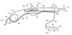
- FIG. 1Ais a side view of a forceps provided in accordance with one embodiment of the present disclosure wherein jaw members of the forceps are disposed in an open configuration;
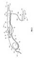
- FIG. 1Bis a side view of the forceps of FIG. 1A wherein the jaw members are disposed in a closed configuration;
- FIG. 2is a side, cross-sectional view of one of the shaft members of the forceps of FIG. 1A ;
- FIG. 3is an exploded, side, perspective view of the other shaft member of the forceps of FIG. 1A ;
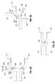
- FIG. 4Ais transverse, cross-sectional view of one embodiment of shaft members configured for use with the forceps of FIG. 1A , wherein the shaft members are disengaged from one another;
- FIG. 4Bis a transverse, cross-sectional view of the shaft members of FIG. 4A during engagement to one another via a pivot pin extending from one of the shaft members;
- FIG. 4Cis a transverse, cross-sectional view of the shaft members of FIG. 4A engaged to one another via the pivot pin;
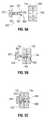
- FIG. 5Ais transverse, cross-sectional view of another embodiment of shaft members configured for use with the forceps of FIG. 1A , wherein the shaft members are disengaged from one another;
- FIG. 5Bis a transverse, cross-sectional view of the shaft members of FIG. 5A shown including a pivot pin being inserted therethrough to engage the shaft members to one another;
- FIG. 5Cis a transverse, cross-sectional view of the shaft members of FIG. 5A shown engaged to one another via the pivot pin;
- FIG. 6Ais an exploded, side view of another embodiment of shaft members configured for use with the forceps of FIG. 1A ;
- FIG. 6Bis a side view of the shaft members of FIG. 6A shown in an unlocked position for engaging and/or disengaging the shaft members to one another;
- FIG. 6Cis a side view of the shaft members of FIG. 6A shown in a locked position
- FIG. 7Ais a side view of another embodiment of a shaft member including an engagement pin extending therefrom;
- FIG. 7Bis top view of the shaft member of FIG. 7A ;
- FIG. 7Cis a side view of a shaft member including an engagement aperture configured to receive the engagement pin of the shaft member of FIG. 7A to engage the shaft members to one another.
- distalrefers to the portion that is being described which is further from a user
- proximalrefers to the portion that is being described which is closer to a user
- a forceps 10including two elongated shaft members 12 a and 12 b each having a distal end 14 a and 14 b and a proximal end 16 a and 16 b , respectively.
- End effector assembly 100including opposing jaw members 110 , 120 , is attached to distal ends 14 a and 14 b of shaft members 12 a and 12 b , respectively.
- a pivot pin 150is interdisposed between shaft members 12 a , 12 b and the respective jaw members 110 , 120 thereof such that shaft members 12 a , 12 b may be pivoted relative to one another between a spaced-apart position ( FIG. 1A ) and an approximated position ( FIG. 1B ) to effect movement of jaw members 110 , 120 relative to one another between an open position ( FIG. 1A ) and a closed position ( FIG. 1B ), respectively, for grasping tissue therebetween.
- Jaw members 110 , 120 of end effector assembly 100each include a jaw frame 112 , 122 that is fixedly engaged to the respective shaft member 12 a , 12 b and an opposed electrically-conductive tissue sealing plate 114 , 124 , respectively, disposed on the respective jaw frame 112 , 122 .
- One or both of electrically-conductive tissue sealing plates 114 , 124 of jaw members 110 , 120are adapted to connect to a source of electrosurgical energy for conducting energy through tissue to seal tissue grasped between jaw members 110 , 120 .
- each shaft member 12 a and 12 bincludes a handle 17 a and 17 b disposed at the proximal end 16 a and 16 b thereof.
- Each handle 17 a and 17 bdefines a finger hole 18 a and 18 b therethrough for receiving a finger of the user.
- finger holes 18 a and 18 bfacilitate movement of shaft members 12 a and 12 b relative to one another between the spaced-apart and approximated positions which, in turn, pivots jaw members 110 and 120 between the open position ( FIG. 1A ) and the closed position ( FIG. 1B ).
- Shaft members 12 a , 12 bare releasably coupled to one another, e.g., via decoupling one or both of shaft members 12 a , 12 b from pivot pin 150 , such that one of the shaft members, e.g., shaft member 12 a , may be disposed of and replaced with a new shaft member 12 a , while the other shaft member, e.g., shaft member 12 b , may be sterilized and/or otherwise treated in preparation for re-use.
- each of the shaft members 12 a , 12 bincludes different components and features suitable for the specific configuration, e.g., disposable or reusable, of the shaft member 12 a , 12 b.
- Shaft member 12 ais configured as a disposable component that is to be disposed of and replaced with a new disposable shaft member 12 a after each use, or each surgical procedure.
- Shaft member 12 aincludes an outer housing 13 a that may be formed from plastic or other suitable material. Outer housing 13 a houses the internal working components of shaft member 12 a .
- Shaft member 12 afurther includes an aperture 160 ( FIGS. 5A-5B ) extending transversely therethrough adjacent distal end 14 a thereof that is configured to receive pivot pin 150 therethrough for pivotably coupling shaft member 12 and shaft member 12 b to one another.
- Pivot pin 150may be removably coupled within aperture 160 ( FIGS. 5A-5B ) defined through shaft member 12 a , or may be fixedly secured therein for releasable coupling with shaft member 12 b to permit pivoting of shaft member 12 b relative to shaft member 12 a and pivot pin 150 from the spaced-apart position ( FIG. 1A ) to the approximated position ( FIG. 1B ) for moving jaw members 110 , 120 between the open and closed positions, respectively.
- a proximal shaft connector 19 aextends proximally from outer housing 13 a of shaft member 12 a .
- Proximal shaft connector 19 ais designed to connect the forceps 10 to a source of electrosurgical energy such as an electrosurgical generator (not shown). More specifically, proximal shaft connector 19 a secures an electrosurgical cable 210 to the forceps 10 such that the user may selectively apply electrosurgical energy to tissue sealing plates 114 , 124 of jaw members 110 , 120 , respectively, e.g., via actuation of activation switch 92 of activation assembly 90 (see FIG. 1A ), to seal tissue grasped therebetween.
- Electrosurgical cable 210includes one or more wires 220 , 222 extending therethrough that extend into outer housing 13 a of shaft member 12 a .
- One more wires 220 , 222extends through shaft member 12 a , ultimately coupling to activation assembly 90 .
- one or more wires, e.g., wire 224extends from activation assembly 90 (and/or electrosurgical cable 210 ), ultimately coupling to tissue sealing plates 114 of jaw members 110
- another wiree.g., wire 226
- tissue sealing plate 124 of removable component 123 of jaw member 120extends from activation assembly 90 through shaft member 12 a and outer of shaft member 12 a towards distal end 14 a thereof.
- Wire 226may include an insulative coating, or sleeve 228 disposed thereabout such that wire 226 is insulated when disposed externally of shaft member 12 a .
- shaft member 12 a(and/or shaft member 12 b ) may include clips, grooves, or other suitable mechanisms (not explicitly shown) for routing wire 226 along the external surface(s) of shaft member(s) 12 a , 12 b such that wire 226 does not interfere with the use and operation of forceps 10 and such that wire 226 does not catch or tangle during use of forceps 10 .
- disposable component 123 of jaw member 120is configured to engage jaw frame 122 of jaw member 120 of reusable shaft 12 b . As such, the user may selectively actuate activation switch 92 of activation assembly 90 to supply energy to tissue sealing plates 114 , 124 of jaw members 110 , 120 , respectively, for sealing tissue grasped therebetween.
- shaft member 12 afurther includes a knife assembly 180 disposed therein and a trigger assembly 80 coupled thereto.
- Trigger assembly 80includes a trigger 82 that is selectively translatable between first and second positions to advance knife blade 182 ( FIG. 3 ) from a retracted position, wherein knife blade 182 is disposed within shaft member 12 a , and an extended position, wherein knife blade 182 extends between jaw members 110 , 120 to cut tissue grasped therebetween. As shown in FIG.
- trigger assembly 80includes a gear mechanism 84 biased by springs 86 for selectively translating knife blade 182 from the retracted position to the extended position upon movement of trigger 82 proximally from the first position to the second position.
- Springs 86bias trigger 82 distally toward the first position and, accordingly, bias knife blade 182 toward the retracted position.
- other trigger assemblies 80 and/or knife assemblies 180may also be provided for use in conjunction with shaft member 12 a , such as those disclosed in commonly-owned U.S. Pat. No. 7,131,970 to Moses et al.
- tissue sealing plates 114 , 124 of jaw members 110 , 120may include a blade slot 188 ( FIGS. 2-3 ) defined therein and extending therethrough.
- Blade slot 188is configured to permit reciprocation of knife blade 182 therethrough.
- Blade slot 188may be defined completely within one of the jaw members, e.g., jaw member 120 , or may be formed partially within each of the jaw members 110 , 120 such that blade slot 188 is formed as jaw members 110 and 120 come together upon pivoting of the jaw members 110 and 120 to the closed position. Further, the blade slot 188 may be configured to facilitate and/or enhance cutting of tissue during reciprocation of the knife blade 182 therethrough.
- Shaft member 12 bmay be formed form any suitable material, e.g., stainless steel, capable of being sterilized, e.g., placed in an autoclave (not shown), or otherwise prepared for reuse.
- Shaft member 12 bfurther includes an aperture 162 defined therein and extending transversely therethrough towards distal end 14 b thereof that is configured to receive pivot pin 150 therethrough for releasably coupling shaft members 12 a and 12 b to one another.
- Shaft member 12 bmay define a partially or entirely solid interior configuration to achieve greater strength and/or may otherwise be configured for increased durability such that shaft member 12 b can be used repeatedly without significant wearing.
- shaft member 12 bincludes jaw frame 122 of jaw member 120 disposed at distal end 14 b thereof.
- Jaw frame 122includes a pair of apertures 125 configured to receive snap-fit protrusions 128 of disposable component 123 for releasably securing disposable component 123 thereon, e.g., in snap-fit engagement therewith, although other releasable engagement configurations are contemplated.
- Disposable component 123includes electrically-conductive tissue sealing plate 124 disposed about an insulative member (not explicitly shown). Snap-fit protrusions 128 extend from the insulative member (not explicitly shown).
- tissue sealing plate 124 of disposable component 123is coupled to the source of energy (not shown) via wire(s) 226 such that jaw member 120 , in conjunction with jaw member 110 may be used to conduct energy through tissue grasped therebetween to seal tissue.
- Reusable shaft member 12 bdefines a relatively simplified, strong, and durable configuration that facilitates sterilization and repeated use of shaft member 12 b
- disposable shaft member 12 aincludes activation assembly 90 , trigger assembly 80 , knife assembly 180 , and the various components and connections associated therewith. Including these various components with shaft member 12 a allows new components to be used for each surgical procedure, obviating the need to make these components sterilizable or configured for long-term repeated use.
- tissue sealing plate 114 of jaw member 110 of disposable shaft 12 aand tissue sealing plate 124 of disposable component 123 of jaw member 120 are also configured as disposable components such that a new set of tissue sealing plates 114 , 124 may be used for each procedure.
- Pivot pin 150is shown fixedly engaged through shaft member 12 a .
- Pivot pin 150further includes a hub 152 disposed at first end 151 thereof and a pair of adjacent legs 154 disposed at second end 153 thereof.
- Legs 154extend from pivot pin 150 and define a living hinge 156 therewith. More specifically, legs 154 are biased towards a spaced-apart position relative to one another, but are moveable against the bias of living hinge 156 toward an approximated position wherein legs 154 are abutting, or disposed in close relation relative to one another to facilitate insertion of pivot pin 150 through aperture 162 of shaft member 12 b .
- Legs 154each further include an outwardly-extending tab 158 disposed at the free ends 157 thereof.
- shaft members 12 a and 12 bare brought into approximation with one another such that pivot pin 150 is inserted through aperture 162 of shaft member 12 b . More specifically, legs 154 of pivot pin 150 and, thus, tabs 158 thereof, are urged, or squeezed toward one another such that pivot pin 150 may be advanced through aperture 162 of shaft member 12 b , as shown in FIG. 4B . As tabs 158 extend from aperture 162 on the other side thereof, legs 154 are permitted to return under the bias of living hinge 156 back toward the spaced-apart position. In this position, as shown in FIG.
- tabs 158extend radially outwardly from aperture 162 about shaft member 12 b to inhibit backing out of pivot pin 150 , thus pivotably engaging shaft members 12 a and 12 b to one another, while still permitting shaft member 12 b to rotate about pivot pin 150 and relative to shaft member 12 a .
- tabs 158are urged, or squeezed toward one another a sufficient distance such that legs 154 may pass back through aperture 162 of shaft member 12 b.
- FIGS. 5A-5Cshow another embodiment of a pivot pin 250 similar to pivot pin 150 ( FIGS. 4A-4C ) except that pivot pin 250 is releasably engagable with both shaft member 12 a and shaft member 12 b .
- living-hinge legs 254 of pivot pin 250extend directly from hub 252 to free ends 257 thereof, i.e., legs 254 extend along the length of pivot pin 250 , although either of pivot pins 150 , 250 may be used in conjunction with the configurations of FIGS. 4A-4C and 5A-5C .
- pivot pin 250In use, legs 254 of pivot pin 250 and, thus, tabs 258 thereof, are urged, or squeezed toward one another such that pivot pin 250 may be advanced through aperture 160 defined within shaft member 12 a and aperture 262 of shaft member 12 b . Ultimately, pivot pin 250 is advanced through shaft members 12 a , 12 b until tabs 258 extend from aperture 262 on the other side thereof. Once this position is achieved, legs 254 are permitted to return under the bias of living hinge 256 back toward the spaced-apart position. In this position, as shown in FIG.
- tabs 258extend radially outwardly from aperture 262 about shaft member 12 b to inhibit backing out of pivot pin 250 , while hub 252 of pivot pin 250 inhibits further advancement of pivot pin 250 through aperture 260 shaft member 12 a . Accordingly, shaft members 12 a and 12 b are pivotably engaged to one another, while still permitting shaft members 12 a and 12 b to rotate about pivot pin 150 relative to one another. Pivot pin 250 is disengaged from shaft members 12 a , 12 b similarly as described above with respect to pivot pin 150 ( FIGS. 4A-4C ).
- pivot pin 350defines a key-like configuration having a hub 352 , an elongated member 354 extending therefrom, and a pair of opposed tabs 358 extending radially outwardly from elongated member 354 at free end 356 thereof.
- Shaft members 12 a , 12 bdefine apertures 360 , 362 , respectively, extending transversely therethrough that are shaped complementarily to pivot pin 350 such that pivot pin 350 may be inserted therethrough.
- shaft members 12 a , 12 beach define a generally circular-shaped aperture 360 , 362 having a pair of opposed recessed portions 361 , 363 , respectively, defined therein for receiving tabs 358 of pivot pin 350 therethrough.
- apertures 360 , 362 disposed on shaft members 12 a , 12 b , respectivelyare offset approximately 90 degrees relative to one another.
- shaft members 12 a , 12 bmust be oriented substantially perpendicularly to one another (the unlocked position), as shown in FIG. 6B , such that apertures 360 , 362 are aligned with one another to permit insertion (or removal) of pivot pin 350 therethrough.
- shaft members 12 a , 12 bare positioned substantially perpendicularly to one another such that apertures 360 , 362 are aligned with one another.
- pivot pin 350may be inserted through apertures 360 , 362 . More specifically, tabs 358 of pivot pin 350 are advanced through recessed portions 361 of aperture 360 of shaft member 12 a and through recessed portions 363 of aperture 362 of shaft member 12 b such that tabs 358 extend from aperture 362 of shaft member 12 b on the other side thereof.
- shaft member 12 bmay be rotated about pivot pin 350 and relative to shaft member 12 a from the unlocked position to the locked position, e.g., the spaced-part position, the approximated position, or any position therebetween, as shown in FIG. 6C .
- the locked positionshaft members 12 a , 12 b are locked in engagement with one another in that pivot pin 350 is inhibited from backing out of aperture 362 of shaft member 12 b due to the offset alignment of tabs 358 relative to recessed portions 363 , and is inhibited from advancing further through aperture 361 of shaft member 12 a due to hub 352 thereof.
- shaft members 12 a , 12 bare still permitted to pivot about pivot pin 350 and relative to one another between the spaced-apart position and the approximated position.
- shaft members 12 a , 12 bare once again moved to the unlocked position, wherein shaft members 12 a , 12 b are positioned substantially perpendicularly relative to one another, thus allowing pivot pin 350 to be removed therefrom.
- shaft member 12 bmay then be sterilized for reuse, while shaft member 12 a is disposed of and a new shaft member 12 a is provided for coupling to shaft member 12 b in preparation for reuse.
- FIGS. 7A-7Canother configuration for engaging shaft members 12 a , 12 b to one another is shown that is substantially similar to the configuration shown in FIGS. 6A-6C except that pivot pin 450 is fixedly secured to shaft member 12 a and extends transversely therefrom.
- the engagement and disengagement of shaft 12 a and 12 bis substantially similar as described above with respect to FIGS. 6A-6C and, thus, will only be summarized herein for purposes of brevity.
- shaft members 12 a , 12 bare positioned substantially perpendicularly to one another such that tabs 458 of pivot pin 450 of shaft member 12 a are aligned with recessed portions 463 of aperture 462 of shaft member 12 b .
- pivot pin 450may be advanced through aperture 462 to extend therefrom on the other side thereof.
- shaft member 12 bmay be rotated about pivot pin 450 and relative to shaft member 12 a from the unlocked position to the locked position.
Landscapes
- Health & Medical Sciences (AREA)
- Life Sciences & Earth Sciences (AREA)
- Surgery (AREA)
- Engineering & Computer Science (AREA)
- Medical Informatics (AREA)
- Veterinary Medicine (AREA)
- Biomedical Technology (AREA)
- Heart & Thoracic Surgery (AREA)
- Nuclear Medicine, Radiotherapy & Molecular Imaging (AREA)
- Molecular Biology (AREA)
- Animal Behavior & Ethology (AREA)
- General Health & Medical Sciences (AREA)
- Public Health (AREA)
- Ophthalmology & Optometry (AREA)
- Physics & Mathematics (AREA)
- Plasma & Fusion (AREA)
- Otolaryngology (AREA)
- Surgical Instruments (AREA)
Abstract
Description
Claims (18)
Priority Applications (1)
| Application Number | Priority Date | Filing Date | Title |
|---|---|---|---|
| US14/628,871US9770253B2 (en) | 2011-08-09 | 2015-02-23 | Surgical forceps |
Applications Claiming Priority (2)
| Application Number | Priority Date | Filing Date | Title |
|---|---|---|---|
| US13/205,999US8968306B2 (en) | 2011-08-09 | 2011-08-09 | Surgical forceps |
| US14/628,871US9770253B2 (en) | 2011-08-09 | 2015-02-23 | Surgical forceps |
Related Parent Applications (1)
| Application Number | Title | Priority Date | Filing Date |
|---|---|---|---|
| US13/205,999ContinuationUS8968306B2 (en) | 2011-08-09 | 2011-08-09 | Surgical forceps |
Publications (2)
| Publication Number | Publication Date |
|---|---|
| US20150164525A1 US20150164525A1 (en) | 2015-06-18 |
| US9770253B2true US9770253B2 (en) | 2017-09-26 |
Family
ID=47668905
Family Applications (2)
| Application Number | Title | Priority Date | Filing Date |
|---|---|---|---|
| US13/205,999Active2033-11-23US8968306B2 (en) | 2011-08-09 | 2011-08-09 | Surgical forceps |
| US14/628,871Active2032-09-22US9770253B2 (en) | 2011-08-09 | 2015-02-23 | Surgical forceps |
Family Applications Before (1)
| Application Number | Title | Priority Date | Filing Date |
|---|---|---|---|
| US13/205,999Active2033-11-23US8968306B2 (en) | 2011-08-09 | 2011-08-09 | Surgical forceps |
Country Status (4)
| Country | Link |
|---|---|
| US (2) | US8968306B2 (en) |
| EP (1) | EP2741703B1 (en) |
| CN (1) | CN103841911B (en) |
| WO (1) | WO2013022928A1 (en) |
Families Citing this family (84)
| Publication number | Priority date | Publication date | Assignee | Title |
|---|---|---|---|---|
| US7364577B2 (en) | 2002-02-11 | 2008-04-29 | Sherwood Services Ag | Vessel sealing system |
| ES2262639T3 (en) | 2001-04-06 | 2006-12-01 | Sherwood Services Ag | SHUTTER AND DIVIDER OF GLASSES WITH BUMPER MEMBERS N OCONDUCTIVES. |
| US7628791B2 (en) | 2005-08-19 | 2009-12-08 | Covidien Ag | Single action tissue sealer |
| US8298232B2 (en) | 2006-01-24 | 2012-10-30 | Tyco Healthcare Group Lp | Endoscopic vessel sealer and divider for large tissue structures |
| US8114122B2 (en) | 2009-01-13 | 2012-02-14 | Tyco Healthcare Group Lp | Apparatus, system, and method for performing an electrosurgical procedure |
| US8187273B2 (en) | 2009-05-07 | 2012-05-29 | Tyco Healthcare Group Lp | Apparatus, system, and method for performing an electrosurgical procedure |
| US8430876B2 (en) | 2009-08-27 | 2013-04-30 | Tyco Healthcare Group Lp | Vessel sealer and divider with knife lockout |
| US8133254B2 (en) | 2009-09-18 | 2012-03-13 | Tyco Healthcare Group Lp | In vivo attachable and detachable end effector assembly and laparoscopic surgical instrument and methods therefor |
| US8112871B2 (en) | 2009-09-28 | 2012-02-14 | Tyco Healthcare Group Lp | Method for manufacturing electrosurgical seal plates |
| US8968306B2 (en) | 2011-08-09 | 2015-03-03 | Covidien Lp | Surgical forceps |
| US8685056B2 (en)* | 2011-08-18 | 2014-04-01 | Covidien Lp | Surgical forceps |
| US8864795B2 (en) | 2011-10-03 | 2014-10-21 | Covidien Lp | Surgical forceps |
| US8968309B2 (en) | 2011-11-10 | 2015-03-03 | Covidien Lp | Surgical forceps |
| US8968310B2 (en) | 2011-11-30 | 2015-03-03 | Covidien Lp | Electrosurgical instrument with a knife blade lockout mechanism |
| US9113897B2 (en) | 2012-01-23 | 2015-08-25 | Covidien Lp | Partitioned surgical instrument |
| US8968360B2 (en) | 2012-01-25 | 2015-03-03 | Covidien Lp | Surgical instrument with resilient driving member and related methods of use |
| US8747434B2 (en) | 2012-02-20 | 2014-06-10 | Covidien Lp | Knife deployment mechanisms for surgical forceps |
| US8887373B2 (en) | 2012-02-24 | 2014-11-18 | Covidien Lp | Vessel sealing instrument with reduced thermal spread and method of manufacture therefor |
| US8961514B2 (en) | 2012-03-06 | 2015-02-24 | Covidien Lp | Articulating surgical apparatus |
| US9375282B2 (en) | 2012-03-26 | 2016-06-28 | Covidien Lp | Light energy sealing, cutting and sensing surgical device |
| US9265569B2 (en) | 2012-03-29 | 2016-02-23 | Covidien Lp | Method of manufacturing an electrosurgical forceps |
| US8968311B2 (en) | 2012-05-01 | 2015-03-03 | Covidien Lp | Surgical instrument with stamped double-flag jaws and actuation mechanism |
| US9668807B2 (en) | 2012-05-01 | 2017-06-06 | Covidien Lp | Simplified spring load mechanism for delivering shaft force of a surgical instrument |
| US9820765B2 (en) | 2012-05-01 | 2017-11-21 | Covidien Lp | Surgical instrument with stamped double-flange jaws |
| US9039731B2 (en) | 2012-05-08 | 2015-05-26 | Covidien Lp | Surgical forceps including blade safety mechanism |
| US9375258B2 (en) | 2012-05-08 | 2016-06-28 | Covidien Lp | Surgical forceps |
| US9265566B2 (en) | 2012-10-16 | 2016-02-23 | Covidien Lp | Surgical instrument |
| US9579147B2 (en) | 2013-06-04 | 2017-02-28 | Ethicon Endo-Surgery, Llc | Electrosurgical forceps with translating blade driver |
| US10499975B2 (en) | 2013-08-07 | 2019-12-10 | Covidien Lp | Bipolar surgical instrument |
| AU2013375909B2 (en)* | 2013-08-07 | 2015-07-30 | Covidien Lp | Bipolar surgical instrument |
| WO2015017989A1 (en) | 2013-08-07 | 2015-02-12 | Covidien Lp | Bipolar surgical instrument |
| USD738499S1 (en)* | 2013-08-07 | 2015-09-08 | Covidien Lp | Open vessel sealer with mechanical cutter |
| AU2013397838B2 (en) | 2013-08-07 | 2018-08-16 | Covidien Lp | Bipolar surgical instrument with tissue stop |
| USD744644S1 (en)* | 2013-08-07 | 2015-12-01 | Covidien Lp | Disposable housing for open vessel sealer with mechanical cutter |
| US20150051599A1 (en)* | 2013-08-16 | 2015-02-19 | Covidien Lp | Limited-use medical device |
| US10231772B2 (en) | 2013-09-25 | 2019-03-19 | Covidien Lp | Wire retention unit for a surgical instrument |
| USD788302S1 (en) | 2013-10-01 | 2017-05-30 | Covidien Lp | Knife for endoscopic electrosurgical forceps |
| US9877777B2 (en) | 2014-09-17 | 2018-01-30 | Covidien Lp | Surgical instrument having a bipolar end effector assembly and a deployable monopolar assembly |
| US10039592B2 (en) | 2014-09-17 | 2018-08-07 | Covidien Lp | Deployment mechanisms for surgical instruments |
| US9987076B2 (en) | 2014-09-17 | 2018-06-05 | Covidien Lp | Multi-function surgical instruments |
| US10080605B2 (en) | 2014-09-17 | 2018-09-25 | Covidien Lp | Deployment mechanisms for surgical instruments |
| US9918785B2 (en) | 2014-09-17 | 2018-03-20 | Covidien Lp | Deployment mechanisms for surgical instruments |
| US10172612B2 (en) | 2015-01-21 | 2019-01-08 | Covidien Lp | Surgical instruments with force applier and methods of use |
| WO2016169039A1 (en)* | 2015-04-24 | 2016-10-27 | Covidien Lp | Disposable connector for use with reusable vessel sealing divider device |
| US10758257B2 (en)* | 2015-04-24 | 2020-09-01 | Covidien Lp | Vessel sealing device with fine dissection function |
| USD844138S1 (en) | 2015-07-17 | 2019-03-26 | Covidien Lp | Handle assembly of a multi-function surgical instrument |
| USD844139S1 (en) | 2015-07-17 | 2019-03-26 | Covidien Lp | Monopolar assembly of a multi-function surgical instrument |
| US10631918B2 (en) | 2015-08-14 | 2020-04-28 | Covidien Lp | Energizable surgical attachment for a mechanical clamp |
| US10213250B2 (en)* | 2015-11-05 | 2019-02-26 | Covidien Lp | Deployment and safety mechanisms for surgical instruments |
| US10537381B2 (en) | 2016-02-26 | 2020-01-21 | Covidien Lp | Surgical instrument having a bipolar end effector assembly and a deployable monopolar assembly |
| US10631887B2 (en) | 2016-08-15 | 2020-04-28 | Covidien Lp | Electrosurgical forceps for video assisted thoracoscopic surgery and other surgical procedures |
| JP6326609B2 (en)* | 2016-12-01 | 2018-05-23 | コヴィディエン リミテッド パートナーシップ | Bipolar surgical instrument |
| US10813695B2 (en) | 2017-01-27 | 2020-10-27 | Covidien Lp | Reflectors for optical-based vessel sealing |
| TWI642401B (en)* | 2017-03-03 | 2018-12-01 | 財團法人工業技術研究院 | Minimally invasive surgical device |
| US11540872B2 (en) | 2017-03-13 | 2023-01-03 | Covidien Lp | Electrosurgical instrument with trigger driven cutting function |
| US10973567B2 (en) | 2017-05-12 | 2021-04-13 | Covidien Lp | Electrosurgical forceps for grasping, treating, and/or dividing tissue |
| US11172980B2 (en) | 2017-05-12 | 2021-11-16 | Covidien Lp | Electrosurgical forceps for grasping, treating, and/or dividing tissue |
| US10653475B2 (en) | 2017-06-08 | 2020-05-19 | Covidien Lp | Knife lockout for electrosurgical forceps |
| USD843574S1 (en) | 2017-06-08 | 2019-03-19 | Covidien Lp | Knife for open vessel sealer |
| USD854684S1 (en) | 2017-06-08 | 2019-07-23 | Covidien Lp | Open vessel sealer with mechanical cutter |
| USD854149S1 (en) | 2017-06-08 | 2019-07-16 | Covidien Lp | End effector for open vessel sealer |
| US11154348B2 (en) | 2017-08-29 | 2021-10-26 | Covidien Lp | Surgical instruments and methods of assembling surgical instruments |
| US11241275B2 (en) | 2018-03-21 | 2022-02-08 | Covidien Lp | Energy-based surgical instrument having multiple operational configurations |
| US11123132B2 (en) | 2018-04-09 | 2021-09-21 | Covidien Lp | Multi-function surgical instruments and assemblies therefor |
| US10828756B2 (en) | 2018-04-24 | 2020-11-10 | Covidien Lp | Disassembly methods facilitating reprocessing of multi-function surgical instruments |
| US10780544B2 (en) | 2018-04-24 | 2020-09-22 | Covidien Lp | Systems and methods facilitating reprocessing of surgical instruments |
| USD904611S1 (en) | 2018-10-10 | 2020-12-08 | Bolder Surgical, Llc | Jaw design for a surgical instrument |
| US11471211B2 (en) | 2018-10-12 | 2022-10-18 | Covidien Lp | Electrosurgical forceps |
| US11376062B2 (en) | 2018-10-12 | 2022-07-05 | Covidien Lp | Electrosurgical forceps |
| US11350982B2 (en) | 2018-12-05 | 2022-06-07 | Covidien Lp | Electrosurgical forceps |
| USD904606S1 (en)* | 2019-02-07 | 2020-12-08 | Aesculap Ag | Surgical hammer |
| US11523861B2 (en) | 2019-03-22 | 2022-12-13 | Covidien Lp | Methods for manufacturing a jaw assembly for an electrosurgical forceps |
| CN110279462A (en)* | 2019-04-09 | 2019-09-27 | 广州派若弥医疗器械有限公司 | A kind of jaw type electric heating melting welding knife |
| EP3744278B1 (en)* | 2019-05-27 | 2024-08-14 | Erbe Elektromedizin GmbH | Electric surgical instrument and method for its manufacture |
| US12402934B2 (en) | 2019-09-15 | 2025-09-02 | Covidien Lp | Electrosurgical instrument for grasping, treating, and/or dividing tissue incorporating thermal management feature |
| US11622804B2 (en) | 2020-03-16 | 2023-04-11 | Covidien Lp | Forceps with linear trigger mechanism |
| CA3183984A1 (en)* | 2020-06-25 | 2021-12-30 | 10129545 Manitoba Ltd. | Surgical tool with retractable blade and bougie passage and a method of use thereof |
| US12295641B2 (en) | 2020-07-01 | 2025-05-13 | Covidien Lp | Electrosurgical forceps with swivel action nerve probe |
| US11660109B2 (en) | 2020-09-08 | 2023-05-30 | Covidien Lp | Cutting elements for surgical instruments such as for use in robotic surgical systems |
| US12185964B2 (en) | 2020-09-10 | 2025-01-07 | Covidien Lp | End effector assemblies for surgical instruments such as for use in robotic surgical systems |
| USD934423S1 (en) | 2020-09-11 | 2021-10-26 | Bolder Surgical, Llc | End effector for a surgical device |
| US12161386B2 (en) | 2020-09-11 | 2024-12-10 | Covidien Lp | Surgical instruments having an articulating section such as for use in robotic surgical systems |
| US11925406B2 (en) | 2020-09-14 | 2024-03-12 | Covidien Lp | End effector assemblies for surgical instruments |
| USD1046129S1 (en) | 2021-04-14 | 2024-10-08 | Bolder Surgical, Llc | End effector for a surgical instrument |
Citations (161)
| Publication number | Priority date | Publication date | Assignee | Title |
|---|---|---|---|---|
| US2619965A (en) | 1950-08-14 | 1952-12-02 | Salo H Goldstone | Scissors with probe used for circumcision |
| US2632661A (en) | 1948-08-14 | 1953-03-24 | Cristofv Cristjo | Joint for surgical instruments |
| US3302648A (en) | 1964-08-13 | 1967-02-07 | Charles E Barry | Clamping implement |
| SU401367A1 (en) | 1971-10-05 | 1973-10-12 | Тернопольский государственный медицинский институт | BIAKTIVNYE ELECTRO SURGICAL INSTRUMENT |
| DE2415263A1 (en) | 1974-03-29 | 1975-10-02 | Aesculap Werke Ag | Surgical H.F. coagulation probe has electrode tongs - with exposed ends of insulated conductors forming tong-jaws |
| DE2514501A1 (en) | 1975-04-03 | 1976-10-21 | Karl Storz | Bipolar coagulation instrument for endoscopes - has two high frequency electrodes looped over central insulating piece |
| DE2627679A1 (en) | 1975-06-26 | 1977-01-13 | Marcel Lamidey | HEMATISTIC HIGH FREQUENCY EXTRACTOR FORCEPS |
| USD249549S (en) | 1976-10-22 | 1978-09-19 | Aspen Laboratories, Inc. | Electrosurgical handle |
| USD263020S (en) | 1980-01-22 | 1982-02-16 | Rau Iii David M | Retractable knife |
| JPS61501068A (en) | 1984-01-30 | 1986-05-29 | ハルコフスキイ ナウチノ−イススレドワテルスキイ インスチチユ−ト オブスチエイ イ ネオトロジノイ ヒルルギイ | bipolar electrosurgical instrument |
| DE3423356C2 (en) | 1984-06-25 | 1986-06-26 | Berchtold Medizin-Elektronik GmbH & Co, 7200 Tuttlingen | Electrosurgical high frequency cutting instrument |
| DE3612646A1 (en) | 1985-04-16 | 1987-04-30 | Ellman International | Electrosurgical handle piece for blades, needles and forceps |
| DE8712328U1 (en) | 1987-09-11 | 1988-02-18 | Jakoubek, Franz, 7201 Emmingen-Liptingen | Endoscopy forceps |
| USD295893S (en) | 1985-09-25 | 1988-05-24 | Acme United Corporation | Disposable surgical clamp |
| USD295894S (en) | 1985-09-26 | 1988-05-24 | Acme United Corporation | Disposable surgical scissors |
| USD298353S (en) | 1986-05-06 | 1988-11-01 | Vitalmetrics, Inc. | Handle for surgical instrument |
| USD299413S (en) | 1985-07-17 | 1989-01-17 | The Stanley Works | Folding pocket saw handle |
| US4914820A (en) | 1988-07-22 | 1990-04-10 | Kai R&D Center Co., Ltd. | Structure for rotation center of scissors |
| JPH055106A (en) | 1990-07-31 | 1993-01-14 | Matsushita Electric Works Ltd | Production of alloy sintered body |
| JPH0540112A (en) | 1991-02-08 | 1993-02-19 | Tokico Ltd | Sample liquid component analyzer |
| USD343453S (en) | 1993-05-05 | 1994-01-18 | Laparomed Corporation | Handle for laparoscopic surgical instrument |
| JPH0630945A (en) | 1992-05-19 | 1994-02-08 | Olympus Optical Co Ltd | Suturing apparatus |
| JPH06502328A (en) | 1990-10-17 | 1994-03-17 | ボストン サイエンティフィック コーポレイション | Surgical instruments and methods |
| JPH06121797A (en) | 1992-02-27 | 1994-05-06 | United States Surgical Corp | Equipment and method for performing intracutaneous stapling of body tissue |
| USD348930S (en) | 1991-10-11 | 1994-07-19 | Ethicon, Inc. | Endoscopic stapler |
| USD349341S (en) | 1992-10-28 | 1994-08-02 | Microsurge, Inc. | Endoscopic grasper |
| JPH06285078A (en) | 1993-04-05 | 1994-10-11 | Olympus Optical Co Ltd | Forceps |
| JPH06343644A (en) | 1993-05-04 | 1994-12-20 | Gyrus Medical Ltd | Surgical peritoneoscope equipment |
| JPH06511401A (en) | 1991-06-07 | 1994-12-22 | バイタル メディカル プロダクツ コーポレイション | Bipolar electrosurgical endoscopic instrument and its method of use |
| USD354564S (en) | 1993-06-25 | 1995-01-17 | Richard-Allan Medical Industries, Inc. | Surgical clip applier |
| DE4303882C2 (en) | 1993-02-10 | 1995-02-09 | Kernforschungsz Karlsruhe | Combination instrument for separation and coagulation for minimally invasive surgery |
| USD358887S (en) | 1993-12-02 | 1995-05-30 | Cobot Medical Corporation | Combined cutting and coagulating forceps |
| DE4403252A1 (en) | 1994-02-03 | 1995-08-10 | Michael Hauser | Instrument shaft for min. invasive surgery |
| JPH07265328A (en) | 1993-11-01 | 1995-10-17 | Gyrus Medical Ltd | Electrode assembly for electric surgery device and electric surgery device using it |
| JPH0856955A (en) | 1994-06-29 | 1996-03-05 | Gyrus Medical Ltd | Electric surgical apparatus |
| DE19515914C1 (en) | 1995-05-02 | 1996-07-25 | Aesculap Ag | Tong or scissor-shaped surgical instrument |
| DE19506363A1 (en) | 1995-02-24 | 1996-08-29 | Frost Lore Geb Haupt | Non-invasive thermometry in organs under hyperthermia and coagulation conditions |
| JPH08252263A (en) | 1994-12-21 | 1996-10-01 | Gyrus Medical Ltd | Electronic surgical incision instrument and electronic surgical incision device using the same |
| JPH08289895A (en) | 1995-04-21 | 1996-11-05 | Olympus Optical Co Ltd | Suture device |
| DE29616210U1 (en) | 1996-09-18 | 1996-11-14 | Olympus Winter & Ibe Gmbh, 22045 Hamburg | Handle for surgical instruments |
| JPH08317934A (en) | 1995-04-12 | 1996-12-03 | Ethicon Endo Surgery Inc | Hemostatic device for electric surgery with adaptable electrode |
| JPH08317936A (en) | 1995-01-18 | 1996-12-03 | Ethicon Endo Surgery Inc | Hemostatic device for electric surgery provided with recessed type and/or crossed type electrode |
| JPH0910223A (en) | 1995-06-23 | 1997-01-14 | Gyrus Medical Ltd | Generator and system for electric operation |
| DE19608716C1 (en) | 1996-03-06 | 1997-04-17 | Aesculap Ag | Bipolar surgical holding instrument |
| JPH09122138A (en) | 1995-10-20 | 1997-05-13 | Ethicon Endo Surgery Inc | Apparatus for operation |
| USD384413S (en) | 1994-10-07 | 1997-09-30 | United States Surgical Corporation | Endoscopic suturing instrument |
| JPH10195A (en) | 1996-03-05 | 1998-01-06 | Ethicon Endo Surgery Inc | Surgical suturing machine with fixing mechanism |
| JPH1024051A (en) | 1995-09-20 | 1998-01-27 | Olympus Optical Co Ltd | Coagulation forceps with separating function |
| DE19751106A1 (en) | 1996-11-27 | 1998-05-28 | Eastman Kodak Co | Laser printer with array of laser diodes |
| JPH10155798A (en) | 1996-12-04 | 1998-06-16 | Asahi Optical Co Ltd | Hot biopsy forceps for endoscopes |
| USH1745H (en) | 1995-09-29 | 1998-08-04 | Paraschac; Joseph F. | Electrosurgical clamping device with insulation limited bipolar electrode |
| USD402028S (en) | 1997-10-10 | 1998-12-01 | Invasatec, Inc. | Hand controller for medical system |
| JPH1147150A (en) | 1997-08-06 | 1999-02-23 | Olympus Optical Co Ltd | Endoscopic surgery appliance |
| JPH1170124A (en) | 1997-05-14 | 1999-03-16 | Ethicon Endo Surgery Inc | Improved electrosurgical hemostatic apparatus having anvil |
| USD408018S (en) | 1996-03-12 | 1999-04-13 | Mcnaughton Patrick J | Switch guard |
| DE19751108A1 (en) | 1997-11-18 | 1999-05-20 | Beger Frank Michael Dipl Desig | Electrosurgical operation tool, especially for diathermy |
| JPH11169381A (en) | 1997-12-15 | 1999-06-29 | Olympus Optical Co Ltd | High frequency treating device |
| JPH11192238A (en) | 1997-10-10 | 1999-07-21 | Ethicon Endo Surgery Inc | Ultrasonic forceps coagulation device improved of pivot-attaching of forceps arm |
| JPH11244298A (en) | 1997-12-19 | 1999-09-14 | Gyrus Medical Ltd | Electric surgical instrument |
| US5951549A (en) | 1996-12-20 | 1999-09-14 | Enable Medical Corporation | Bipolar electrosurgical scissors |
| USD416089S (en) | 1996-04-08 | 1999-11-02 | Richard-Allan Medical Industries, Inc. | Endoscopic linear stapling and dividing surgical instrument |
| JP2000102545A (en) | 1997-06-18 | 2000-04-11 | Eggers & Associates Inc | Electric tweezers for surgery |
| US6050996A (en) | 1997-11-12 | 2000-04-18 | Sherwood Services Ag | Bipolar electrosurgical instrument with replaceable electrodes |
| USD424694S (en) | 1998-10-23 | 2000-05-09 | Sherwood Services Ag | Forceps |
| USD425201S (en) | 1998-10-23 | 2000-05-16 | Sherwood Services Ag | Disposable electrode assembly |
| WO2000036986A1 (en) | 1998-12-18 | 2000-06-29 | Karl Storz Gmbh & Co. Kg | Bipolar medical instrument |
| USH1904H (en) | 1997-05-14 | 2000-10-03 | Ethicon Endo-Surgery, Inc. | Electrosurgical hemostatic method and device |
| WO2000059392A1 (en) | 1999-04-01 | 2000-10-12 | Erbe Elektromedizin | Surgical instrument |
| JP2000342599A (en) | 1999-05-21 | 2000-12-12 | Gyrus Medical Ltd | Generator for electrosurgical operation, electrosurgical operation system, method for operating this system and method for performing amputation and resection of tissue by electrosurgical operation |
| JP2000350732A (en) | 1999-05-21 | 2000-12-19 | Gyrus Medical Ltd | Electrosurgical system, generator for electrosurgery, and method for cutting or excising tissue by electrosurgery |
| JP2001003400A (en) | 1999-06-21 | 2001-01-09 | Sumitomo Constr Mach Co Ltd | Monitor device for hydraulic shovel |
| JP2001008944A (en) | 1999-05-28 | 2001-01-16 | Gyrus Medical Ltd | Electric surgical signal generator and electric surgical system |
| JP2001029356A (en) | 1999-06-11 | 2001-02-06 | Gyrus Medical Ltd | Electric and surgical signal generator |
| WO2001015614A1 (en) | 1999-08-27 | 2001-03-08 | Karl Storz Gmbh & Co. Kg | Bipolar medical instrument |
| JP2001128990A (en) | 1999-05-28 | 2001-05-15 | Gyrus Medical Ltd | Electro surgical instrument and electrosurgical tool converter |
| DE19946527C1 (en) | 1999-09-28 | 2001-07-12 | Storz Karl Gmbh & Co Kg | Bipolar, e.g. laparoscopic surgery instrument, cuts electrically, cauterizes and grips using simple design with high frequency current-concentrating projections |
| JP2001190564A (en) | 2000-01-12 | 2001-07-17 | Olympus Optical Co Ltd | Medical treatment instrument |
| WO2001054604A1 (en) | 2000-01-25 | 2001-08-02 | Aesculap Ag & Co. Kg | Bipolar gripping device |
| US6277117B1 (en) | 1998-10-23 | 2001-08-21 | Sherwood Services Ag | Open vessel sealing forceps with disposable electrodes |
| USD449886S1 (en) | 1998-10-23 | 2001-10-30 | Sherwood Services Ag | Forceps with disposable electrode |
| EP1159926A2 (en) | 2000-06-03 | 2001-12-05 | Aesculap Ag | Scissor- or forceps-like surgical instrument |
| USD453923S1 (en) | 2000-11-16 | 2002-02-26 | Carling Technologies, Inc. | Electrical rocker switch guard |
| USD454951S1 (en) | 2001-02-27 | 2002-03-26 | Visionary Biomedical, Inc. | Steerable catheter |
| DE20121161U1 (en) | 2001-01-31 | 2002-04-04 | Olympus Winter & Ibe Gmbh, 22045 Hamburg | Endoscopic instrument |
| JP2002136525A (en) | 2000-10-30 | 2002-05-14 | Olympus Optical Co Ltd | Surgical instrument |
| USD457959S1 (en) | 2001-04-06 | 2002-05-28 | Sherwood Services Ag | Vessel sealer |
| USD457958S1 (en) | 2001-04-06 | 2002-05-28 | Sherwood Services Ag | Vessel sealer and divider |
| WO2002045589A2 (en) | 2000-12-08 | 2002-06-13 | Gfd Gesellschaft Für Diamantprodukte Mbh | Instrument, which is provided for surgical applications and which comprises contact areas made of doped diamond, and method for cleaning the instrument |
| JP2002528166A (en) | 1998-10-23 | 2002-09-03 | シャーウッド サーヴィシス アクチェンゲゼルシャフト | Externally-opened vascular sealing forceps with disposable electrodes |
| DE10045375C2 (en) | 2000-09-14 | 2002-10-24 | Aesculap Ag & Co Kg | Medical instrument |
| USD465281S1 (en) | 1999-09-21 | 2002-11-05 | Karl Storz Gmbh & Co. Kg | Endoscopic medical instrument |
| USD466209S1 (en) | 2001-02-27 | 2002-11-26 | Visionary Biomedical, Inc. | Steerable catheter |
| US20020188294A1 (en) | 2001-04-06 | 2002-12-12 | Couture Gary M. | Vessel sealer and divider |
| EP1281878A1 (en) | 2001-08-02 | 2003-02-05 | Peugeot Citroen Automobiles | Pivot pin between two elements |
| US20030109875A1 (en) | 1999-10-22 | 2003-06-12 | Tetzlaff Philip M. | Open vessel sealing forceps with disposable electrodes |
| JP2003175052A (en) | 2002-11-01 | 2003-06-24 | Olympus Optical Co Ltd | Coagulation treatment tool |
| JP2003245285A (en) | 2002-01-23 | 2003-09-02 | Ethicon Endo Surgery Inc | Feedback light apparatus and method for use with electrosurgical instrument |
| US20030171747A1 (en) | 1999-01-25 | 2003-09-11 | Olympus Optical Co., Ltd. | Medical treatment instrument |
| JP2004517668A (en) | 2000-10-20 | 2004-06-17 | オーナックス・メディカル・インコーポレーテッド | Surgical suturing instrument and method of use |
| USD493888S1 (en) | 2003-02-04 | 2004-08-03 | Sherwood Services Ag | Electrosurgical pencil with pistol grip |
| JP2004528869A (en) | 2001-01-26 | 2004-09-24 | エシコン・エンド−サージェリィ・インコーポレイテッド | Electrosurgical instruments for coagulation and cutting |
| USD496997S1 (en) | 2003-05-15 | 2004-10-05 | Sherwood Services Ag | Vessel sealer and divider |
| USD499181S1 (en) | 2003-05-15 | 2004-11-30 | Sherwood Services Ag | Handle for a vessel sealer and divider |
| USD502994S1 (en) | 2003-05-21 | 2005-03-15 | Blake, Iii Joseph W | Repeating multi-clip applier |
| US20050119655A1 (en) | 2003-11-19 | 2005-06-02 | Moses Michael C. | Open vessel sealing instrument with cutting mechanism |
| USD509297S1 (en) | 2003-10-17 | 2005-09-06 | Tyco Healthcare Group, Lp | Surgical instrument |
| JP2005253789A (en) | 2004-03-12 | 2005-09-22 | Olympus Corp | Treatment instrument for operation |
| WO2005110264A2 (en) | 2004-05-14 | 2005-11-24 | Erbe Elektromedizin Gmbh | Electrosurgical instrument |
| JP2006015078A (en) | 2004-07-05 | 2006-01-19 | Olympus Corp | Medical apparatus |
| JP2006501939A (en) | 2002-10-04 | 2006-01-19 | シャーウッド・サービシーズ・アクチェンゲゼルシャフト | Electrode assembly for sealing and cutting tissue and method for performing sealing and cutting tissue |
| WO2006021269A1 (en) | 2004-08-24 | 2006-03-02 | Erbe Elektromedizin Gmbh | Surgical instrument |
| JP2006095316A (en) | 2004-09-29 | 2006-04-13 | Sherwood Services Ag | Vessel sealer and divider having elongated knife stroke and safety for cutting mechanism |
| US7041102B2 (en) | 2001-10-22 | 2006-05-09 | Surgrx, Inc. | Electrosurgical working end with replaceable cartridges |
| USD525361S1 (en) | 2004-10-06 | 2006-07-18 | Sherwood Services Ag | Hemostat style elongated dissecting and dividing instrument |
| US20060167452A1 (en) | 2005-01-14 | 2006-07-27 | Moses Michael C | Open vessel sealing instrument |
| USD531311S1 (en) | 2004-10-06 | 2006-10-31 | Sherwood Services Ag | Pistol grip style elongated dissecting and dividing instrument |
| USD533274S1 (en) | 2004-10-12 | 2006-12-05 | Allegiance Corporation | Handle for surgical suction-irrigation device |
| USD533942S1 (en) | 2004-06-30 | 2006-12-19 | Sherwood Services Ag | Open vessel sealer with mechanical cutter |
| USD535027S1 (en) | 2004-10-06 | 2007-01-09 | Sherwood Services Ag | Low profile vessel sealing and cutting mechanism |
| US7179258B2 (en) | 1997-11-12 | 2007-02-20 | Sherwood Services Ag | Bipolar electrosurgical instrument for sealing vessels |
| USD538932S1 (en) | 2005-06-30 | 2007-03-20 | Medical Action Industries Inc. | Surgical needle holder |
| USD541418S1 (en) | 2004-10-06 | 2007-04-24 | Sherwood Services Ag | Lung sealing device |
| USD541611S1 (en) | 2006-01-26 | 2007-05-01 | Robert Bosch Gmbh | Cordless screwdriver |
| USD541938S1 (en) | 2004-04-09 | 2007-05-01 | Sherwood Services Ag | Open vessel sealer with mechanical cutter |
| USD545432S1 (en) | 2003-08-08 | 2007-06-26 | Olympus Corporation | Distal portion of hemostatic forceps for endoscope |
| USD547154S1 (en) | 2006-09-08 | 2007-07-24 | Winsource Industries Limited | Rotary driving tool |
| DE202007009165U1 (en) | 2007-06-29 | 2007-08-30 | Kls Martin Gmbh + Co. Kg | Surgical instrument e.g. tube shaft, for use in e.g. high frequency coagulation instrument, has separator inserted through opening such that largest extension of opening transverse to moving direction corresponds to dimension of separator |
| DE202007009318U1 (en) | 2007-06-26 | 2007-08-30 | Aesculap Ag & Co. Kg | Surgical instrument |
| DE202007009317U1 (en) | 2007-06-26 | 2007-08-30 | Aesculap Ag & Co. Kg | Surgical instrument |
| US20070260241A1 (en) | 2006-05-04 | 2007-11-08 | Sherwood Services Ag | Open vessel sealing forceps disposable handswitch |
| DE10031773B4 (en) | 2000-05-04 | 2007-11-29 | Erbe Elektromedizin Gmbh | Surgical gripping instrument, in particular tweezers or forceps |
| US7318725B2 (en) | 2004-02-19 | 2008-01-15 | Helmut Zepf Medizintechnik Gmbh | Dental pliers |
| DE202007016233U1 (en) | 2007-11-20 | 2008-01-31 | Aesculap Ag & Co. Kg | Surgical forceps |
| USD564662S1 (en) | 2004-10-13 | 2008-03-18 | Sherwood Services Ag | Hourglass-shaped knife for electrosurgical forceps |
| WO2008040483A1 (en) | 2006-10-05 | 2008-04-10 | Erbe Elektromedizin Gmbh | Tubular shaft instrument |
| USD567943S1 (en) | 2004-10-08 | 2008-04-29 | Sherwood Services Ag | Over-ratchet safety for a vessel sealing instrument |
| US7393348B2 (en) | 2002-09-05 | 2008-07-01 | Aesculap Ag & Co. Kg | Two-part medical instrument |
| USD575395S1 (en) | 2007-02-15 | 2008-08-19 | Tyco Healthcare Group Lp | Hemostat style elongated dissecting and dividing instrument |
| USD575401S1 (en) | 2007-06-12 | 2008-08-19 | Tyco Healthcare Group Lp | Vessel sealer |
| USD582038S1 (en) | 2004-10-13 | 2008-12-02 | Medtronic, Inc. | Transurethral needle ablation device |
| DE19738457B4 (en) | 1997-09-03 | 2009-01-02 | Celon Ag Medical Instruments | Method and device for in vivo deep coagulation of biological tissue volumes while sparing the tissue surface with high frequency alternating current |
| DE102008018406B3 (en) | 2008-04-10 | 2009-07-23 | Bowa-Electronic Gmbh & Co. Kg | Electrosurgical device |
| CN201299462Y (en) | 2008-10-28 | 2009-09-02 | 宋洪海 | Multi-layer metal composite pot |
| US20090255130A1 (en) | 2006-12-01 | 2009-10-15 | Sundtorp Innovation Ab | Instrument |
| USD617903S1 (en) | 2009-05-13 | 2010-06-15 | Tyco Healthcare Group Lp | End effector pointed tip |
| USD617902S1 (en) | 2009-05-13 | 2010-06-15 | Tyco Healthcare Group Lp | End effector tip with undercut top jaw |
| USD617900S1 (en) | 2009-05-13 | 2010-06-15 | Tyco Healthcare Group Lp | End effector tip with undercut bottom jaw |
| USD617901S1 (en) | 2009-05-13 | 2010-06-15 | Tyco Healthcare Group Lp | End effector chamfered tip |
| USD618798S1 (en) | 2009-05-13 | 2010-06-29 | Tyco Healthcare Group Lp | Vessel sealing jaw seal plate |
| USD621503S1 (en) | 2009-04-28 | 2010-08-10 | Tyco Healthcare Group Ip | Pistol grip laparoscopic sealing and dissection device |
| USD627462S1 (en) | 2009-09-09 | 2010-11-16 | Tyco Healthcare Group Lp | Knife channel of a jaw device |
| USD628290S1 (en) | 2009-11-30 | 2010-11-30 | Tyco Healthcare Group Lp | Surgical instrument handle |
| USD628289S1 (en) | 2009-11-30 | 2010-11-30 | Tyco Healthcare Group Lp | Surgical instrument handle |
| USD630324S1 (en) | 2009-08-05 | 2011-01-04 | Tyco Healthcare Group Lp | Dissecting surgical jaw |
| WO2011068795A1 (en) | 2009-12-01 | 2011-06-09 | Illinois Tool Works Inc. | A self-locking automotive accessory for a vehicle body part |
| JP2011125195A (en) | 2009-12-14 | 2011-06-23 | Chugoku Electric Power Co Inc:The | Supporter for indirect hot-line work |
| USD649249S1 (en) | 2007-02-15 | 2011-11-22 | Tyco Healthcare Group Lp | End effectors of an elongated dissecting and dividing instrument |
| USD649643S1 (en) | 2009-05-13 | 2011-11-29 | Tyco Healthcare Group Lp | End effector with a rounded tip |
| US8152834B2 (en) | 2005-04-13 | 2012-04-10 | Synthes Usa, Llc | Forceps and system using same |
| USD661394S1 (en) | 2011-02-24 | 2012-06-05 | Tyco Healthcare Group Lp | Device jaw |
| US8968306B2 (en) | 2011-08-09 | 2015-03-03 | Covidien Lp | Surgical forceps |
Family Cites Families (7)
| Publication number | Priority date | Publication date | Assignee | Title |
|---|---|---|---|---|
| JPS60211451A (en) | 1984-04-05 | 1985-10-23 | Asahi Chem Ind Co Ltd | Photosensitive elastomer composition |
| JPH0540112Y2 (en) | 1987-03-03 | 1993-10-12 | ||
| WO1999012488A1 (en)* | 1997-09-10 | 1999-03-18 | Sherwood Services Ag | Bipolar instrument for vessel fusion |
| US6174309B1 (en)* | 1999-02-11 | 2001-01-16 | Medical Scientific, Inc. | Seal & cut electrosurgical instrument |
| US6440085B1 (en)* | 2001-06-12 | 2002-08-27 | Jacek Krzyzanowski | Method of assembling a non-metallic biopsy forceps jaw and a non-metallic biopsy forceps jaw |
| CN2738746Y (en)* | 2004-10-19 | 2005-11-09 | 寿张根 | Disposable medical electric knife |
| US7862561B2 (en)* | 2005-01-08 | 2011-01-04 | Boston Scientific Scimed, Inc. | Clamp based lesion formation apparatus with variable spacing structures |
- 2011
- 2011-08-09USUS13/205,999patent/US8968306B2/enactiveActive
- 2012
- 2012-08-08EPEP12822762.6Apatent/EP2741703B1/enactiveActive
- 2012-08-08CNCN201280036042.XApatent/CN103841911B/enactiveActive
- 2012-08-08WOPCT/US2012/049928patent/WO2013022928A1/enactiveApplication Filing
- 2015
- 2015-02-23USUS14/628,871patent/US9770253B2/enactiveActive
Patent Citations (164)
| Publication number | Priority date | Publication date | Assignee | Title |
|---|---|---|---|---|
| US2632661A (en) | 1948-08-14 | 1953-03-24 | Cristofv Cristjo | Joint for surgical instruments |
| US2619965A (en) | 1950-08-14 | 1952-12-02 | Salo H Goldstone | Scissors with probe used for circumcision |
| US3302648A (en) | 1964-08-13 | 1967-02-07 | Charles E Barry | Clamping implement |
| SU401367A1 (en) | 1971-10-05 | 1973-10-12 | Тернопольский государственный медицинский институт | BIAKTIVNYE ELECTRO SURGICAL INSTRUMENT |
| DE2415263A1 (en) | 1974-03-29 | 1975-10-02 | Aesculap Werke Ag | Surgical H.F. coagulation probe has electrode tongs - with exposed ends of insulated conductors forming tong-jaws |
| DE2514501A1 (en) | 1975-04-03 | 1976-10-21 | Karl Storz | Bipolar coagulation instrument for endoscopes - has two high frequency electrodes looped over central insulating piece |
| DE2627679A1 (en) | 1975-06-26 | 1977-01-13 | Marcel Lamidey | HEMATISTIC HIGH FREQUENCY EXTRACTOR FORCEPS |
| USD249549S (en) | 1976-10-22 | 1978-09-19 | Aspen Laboratories, Inc. | Electrosurgical handle |
| USD263020S (en) | 1980-01-22 | 1982-02-16 | Rau Iii David M | Retractable knife |
| JPS61501068A (en) | 1984-01-30 | 1986-05-29 | ハルコフスキイ ナウチノ−イススレドワテルスキイ インスチチユ−ト オブスチエイ イ ネオトロジノイ ヒルルギイ | bipolar electrosurgical instrument |
| DE3423356C2 (en) | 1984-06-25 | 1986-06-26 | Berchtold Medizin-Elektronik GmbH & Co, 7200 Tuttlingen | Electrosurgical high frequency cutting instrument |
| DE3612646A1 (en) | 1985-04-16 | 1987-04-30 | Ellman International | Electrosurgical handle piece for blades, needles and forceps |
| USD299413S (en) | 1985-07-17 | 1989-01-17 | The Stanley Works | Folding pocket saw handle |
| USD295893S (en) | 1985-09-25 | 1988-05-24 | Acme United Corporation | Disposable surgical clamp |
| USD295894S (en) | 1985-09-26 | 1988-05-24 | Acme United Corporation | Disposable surgical scissors |
| USD298353S (en) | 1986-05-06 | 1988-11-01 | Vitalmetrics, Inc. | Handle for surgical instrument |
| DE8712328U1 (en) | 1987-09-11 | 1988-02-18 | Jakoubek, Franz, 7201 Emmingen-Liptingen | Endoscopy forceps |
| US4914820A (en) | 1988-07-22 | 1990-04-10 | Kai R&D Center Co., Ltd. | Structure for rotation center of scissors |
| JPH055106A (en) | 1990-07-31 | 1993-01-14 | Matsushita Electric Works Ltd | Production of alloy sintered body |
| JPH06502328A (en) | 1990-10-17 | 1994-03-17 | ボストン サイエンティフィック コーポレイション | Surgical instruments and methods |
| JPH0540112A (en) | 1991-02-08 | 1993-02-19 | Tokico Ltd | Sample liquid component analyzer |
| JPH06511401A (en) | 1991-06-07 | 1994-12-22 | バイタル メディカル プロダクツ コーポレイション | Bipolar electrosurgical endoscopic instrument and its method of use |
| USD348930S (en) | 1991-10-11 | 1994-07-19 | Ethicon, Inc. | Endoscopic stapler |
| JPH06121797A (en) | 1992-02-27 | 1994-05-06 | United States Surgical Corp | Equipment and method for performing intracutaneous stapling of body tissue |
| JPH0630945A (en) | 1992-05-19 | 1994-02-08 | Olympus Optical Co Ltd | Suturing apparatus |
| USD349341S (en) | 1992-10-28 | 1994-08-02 | Microsurge, Inc. | Endoscopic grasper |
| DE4303882C2 (en) | 1993-02-10 | 1995-02-09 | Kernforschungsz Karlsruhe | Combination instrument for separation and coagulation for minimally invasive surgery |
| JPH06285078A (en) | 1993-04-05 | 1994-10-11 | Olympus Optical Co Ltd | Forceps |
| JPH06343644A (en) | 1993-05-04 | 1994-12-20 | Gyrus Medical Ltd | Surgical peritoneoscope equipment |
| USD343453S (en) | 1993-05-05 | 1994-01-18 | Laparomed Corporation | Handle for laparoscopic surgical instrument |
| USD354564S (en) | 1993-06-25 | 1995-01-17 | Richard-Allan Medical Industries, Inc. | Surgical clip applier |
| JPH07265328A (en) | 1993-11-01 | 1995-10-17 | Gyrus Medical Ltd | Electrode assembly for electric surgery device and electric surgery device using it |
| USD358887S (en) | 1993-12-02 | 1995-05-30 | Cobot Medical Corporation | Combined cutting and coagulating forceps |
| DE4403252A1 (en) | 1994-02-03 | 1995-08-10 | Michael Hauser | Instrument shaft for min. invasive surgery |
| JPH0856955A (en) | 1994-06-29 | 1996-03-05 | Gyrus Medical Ltd | Electric surgical apparatus |
| USD384413S (en) | 1994-10-07 | 1997-09-30 | United States Surgical Corporation | Endoscopic suturing instrument |
| JPH08252263A (en) | 1994-12-21 | 1996-10-01 | Gyrus Medical Ltd | Electronic surgical incision instrument and electronic surgical incision device using the same |
| JPH08317936A (en) | 1995-01-18 | 1996-12-03 | Ethicon Endo Surgery Inc | Hemostatic device for electric surgery provided with recessed type and/or crossed type electrode |
| DE19506363A1 (en) | 1995-02-24 | 1996-08-29 | Frost Lore Geb Haupt | Non-invasive thermometry in organs under hyperthermia and coagulation conditions |
| JPH08317934A (en) | 1995-04-12 | 1996-12-03 | Ethicon Endo Surgery Inc | Hemostatic device for electric surgery with adaptable electrode |
| JPH08289895A (en) | 1995-04-21 | 1996-11-05 | Olympus Optical Co Ltd | Suture device |
| DE19515914C1 (en) | 1995-05-02 | 1996-07-25 | Aesculap Ag | Tong or scissor-shaped surgical instrument |
| JPH0910223A (en) | 1995-06-23 | 1997-01-14 | Gyrus Medical Ltd | Generator and system for electric operation |
| JPH1024051A (en) | 1995-09-20 | 1998-01-27 | Olympus Optical Co Ltd | Coagulation forceps with separating function |
| USH1745H (en) | 1995-09-29 | 1998-08-04 | Paraschac; Joseph F. | Electrosurgical clamping device with insulation limited bipolar electrode |
| JPH09122138A (en) | 1995-10-20 | 1997-05-13 | Ethicon Endo Surgery Inc | Apparatus for operation |
| JPH10195A (en) | 1996-03-05 | 1998-01-06 | Ethicon Endo Surgery Inc | Surgical suturing machine with fixing mechanism |
| DE19608716C1 (en) | 1996-03-06 | 1997-04-17 | Aesculap Ag | Bipolar surgical holding instrument |
| USD408018S (en) | 1996-03-12 | 1999-04-13 | Mcnaughton Patrick J | Switch guard |
| USD416089S (en) | 1996-04-08 | 1999-11-02 | Richard-Allan Medical Industries, Inc. | Endoscopic linear stapling and dividing surgical instrument |
| DE29616210U1 (en) | 1996-09-18 | 1996-11-14 | Olympus Winter & Ibe Gmbh, 22045 Hamburg | Handle for surgical instruments |
| DE19751106A1 (en) | 1996-11-27 | 1998-05-28 | Eastman Kodak Co | Laser printer with array of laser diodes |
| JPH10155798A (en) | 1996-12-04 | 1998-06-16 | Asahi Optical Co Ltd | Hot biopsy forceps for endoscopes |
| US5951549A (en) | 1996-12-20 | 1999-09-14 | Enable Medical Corporation | Bipolar electrosurgical scissors |
| JPH1170124A (en) | 1997-05-14 | 1999-03-16 | Ethicon Endo Surgery Inc | Improved electrosurgical hemostatic apparatus having anvil |
| USH2037H1 (en) | 1997-05-14 | 2002-07-02 | David C. Yates | Electrosurgical hemostatic device including an anvil |
| USH1904H (en) | 1997-05-14 | 2000-10-03 | Ethicon Endo-Surgery, Inc. | Electrosurgical hemostatic method and device |
| JP2000102545A (en) | 1997-06-18 | 2000-04-11 | Eggers & Associates Inc | Electric tweezers for surgery |
| JPH1147150A (en) | 1997-08-06 | 1999-02-23 | Olympus Optical Co Ltd | Endoscopic surgery appliance |
| DE19738457B4 (en) | 1997-09-03 | 2009-01-02 | Celon Ag Medical Instruments | Method and device for in vivo deep coagulation of biological tissue volumes while sparing the tissue surface with high frequency alternating current |
| JPH11192238A (en) | 1997-10-10 | 1999-07-21 | Ethicon Endo Surgery Inc | Ultrasonic forceps coagulation device improved of pivot-attaching of forceps arm |
| USD402028S (en) | 1997-10-10 | 1998-12-01 | Invasatec, Inc. | Hand controller for medical system |
| US6050996A (en) | 1997-11-12 | 2000-04-18 | Sherwood Services Ag | Bipolar electrosurgical instrument with replaceable electrodes |
| US7179258B2 (en) | 1997-11-12 | 2007-02-20 | Sherwood Services Ag | Bipolar electrosurgical instrument for sealing vessels |
| DE19751108A1 (en) | 1997-11-18 | 1999-05-20 | Beger Frank Michael Dipl Desig | Electrosurgical operation tool, especially for diathermy |
| JPH11169381A (en) | 1997-12-15 | 1999-06-29 | Olympus Optical Co Ltd | High frequency treating device |
| JPH11244298A (en) | 1997-12-19 | 1999-09-14 | Gyrus Medical Ltd | Electric surgical instrument |
| JP2002528166A (en) | 1998-10-23 | 2002-09-03 | シャーウッド サーヴィシス アクチェンゲゼルシャフト | Externally-opened vascular sealing forceps with disposable electrodes |
| USD425201S (en) | 1998-10-23 | 2000-05-16 | Sherwood Services Ag | Disposable electrode assembly |
| USD424694S (en) | 1998-10-23 | 2000-05-09 | Sherwood Services Ag | Forceps |
| US6277117B1 (en) | 1998-10-23 | 2001-08-21 | Sherwood Services Ag | Open vessel sealing forceps with disposable electrodes |
| USD449886S1 (en) | 1998-10-23 | 2001-10-30 | Sherwood Services Ag | Forceps with disposable electrode |
| WO2000036986A1 (en) | 1998-12-18 | 2000-06-29 | Karl Storz Gmbh & Co. Kg | Bipolar medical instrument |
| US20030171747A1 (en) | 1999-01-25 | 2003-09-11 | Olympus Optical Co., Ltd. | Medical treatment instrument |
| WO2000059392A1 (en) | 1999-04-01 | 2000-10-12 | Erbe Elektromedizin | Surgical instrument |
| JP2000342599A (en) | 1999-05-21 | 2000-12-12 | Gyrus Medical Ltd | Generator for electrosurgical operation, electrosurgical operation system, method for operating this system and method for performing amputation and resection of tissue by electrosurgical operation |
| JP2000350732A (en) | 1999-05-21 | 2000-12-19 | Gyrus Medical Ltd | Electrosurgical system, generator for electrosurgery, and method for cutting or excising tissue by electrosurgery |
| JP2001128990A (en) | 1999-05-28 | 2001-05-15 | Gyrus Medical Ltd | Electro surgical instrument and electrosurgical tool converter |
| JP2001008944A (en) | 1999-05-28 | 2001-01-16 | Gyrus Medical Ltd | Electric surgical signal generator and electric surgical system |
| JP2001029356A (en) | 1999-06-11 | 2001-02-06 | Gyrus Medical Ltd | Electric and surgical signal generator |
| JP2001003400A (en) | 1999-06-21 | 2001-01-09 | Sumitomo Constr Mach Co Ltd | Monitor device for hydraulic shovel |
| WO2001015614A1 (en) | 1999-08-27 | 2001-03-08 | Karl Storz Gmbh & Co. Kg | Bipolar medical instrument |
| USD465281S1 (en) | 1999-09-21 | 2002-11-05 | Karl Storz Gmbh & Co. Kg | Endoscopic medical instrument |
| DE19946527C1 (en) | 1999-09-28 | 2001-07-12 | Storz Karl Gmbh & Co Kg | Bipolar, e.g. laparoscopic surgery instrument, cuts electrically, cauterizes and grips using simple design with high frequency current-concentrating projections |
| US20030109875A1 (en) | 1999-10-22 | 2003-06-12 | Tetzlaff Philip M. | Open vessel sealing forceps with disposable electrodes |
| JP2001190564A (en) | 2000-01-12 | 2001-07-17 | Olympus Optical Co Ltd | Medical treatment instrument |
| WO2001054604A1 (en) | 2000-01-25 | 2001-08-02 | Aesculap Ag & Co. Kg | Bipolar gripping device |
| DE10031773B4 (en) | 2000-05-04 | 2007-11-29 | Erbe Elektromedizin Gmbh | Surgical gripping instrument, in particular tweezers or forceps |
| EP1159926A2 (en) | 2000-06-03 | 2001-12-05 | Aesculap Ag | Scissor- or forceps-like surgical instrument |
| DE10045375C2 (en) | 2000-09-14 | 2002-10-24 | Aesculap Ag & Co Kg | Medical instrument |
| JP2004517668A (en) | 2000-10-20 | 2004-06-17 | オーナックス・メディカル・インコーポレーテッド | Surgical suturing instrument and method of use |
| JP2002136525A (en) | 2000-10-30 | 2002-05-14 | Olympus Optical Co Ltd | Surgical instrument |
| USD453923S1 (en) | 2000-11-16 | 2002-02-26 | Carling Technologies, Inc. | Electrical rocker switch guard |
| WO2002045589A2 (en) | 2000-12-08 | 2002-06-13 | Gfd Gesellschaft Für Diamantprodukte Mbh | Instrument, which is provided for surgical applications and which comprises contact areas made of doped diamond, and method for cleaning the instrument |
| JP2004528869A (en) | 2001-01-26 | 2004-09-24 | エシコン・エンド−サージェリィ・インコーポレイテッド | Electrosurgical instruments for coagulation and cutting |
| DE20121161U1 (en) | 2001-01-31 | 2002-04-04 | Olympus Winter & Ibe Gmbh, 22045 Hamburg | Endoscopic instrument |
| USD466209S1 (en) | 2001-02-27 | 2002-11-26 | Visionary Biomedical, Inc. | Steerable catheter |
| USD454951S1 (en) | 2001-02-27 | 2002-03-26 | Visionary Biomedical, Inc. | Steerable catheter |
| US20020188294A1 (en) | 2001-04-06 | 2002-12-12 | Couture Gary M. | Vessel sealer and divider |
| USD457958S1 (en) | 2001-04-06 | 2002-05-28 | Sherwood Services Ag | Vessel sealer and divider |
| USD457959S1 (en) | 2001-04-06 | 2002-05-28 | Sherwood Services Ag | Vessel sealer |
| EP1281878A1 (en) | 2001-08-02 | 2003-02-05 | Peugeot Citroen Automobiles | Pivot pin between two elements |
| US7041102B2 (en) | 2001-10-22 | 2006-05-09 | Surgrx, Inc. | Electrosurgical working end with replaceable cartridges |
| JP2003245285A (en) | 2002-01-23 | 2003-09-02 | Ethicon Endo Surgery Inc | Feedback light apparatus and method for use with electrosurgical instrument |
| US7393348B2 (en) | 2002-09-05 | 2008-07-01 | Aesculap Ag & Co. Kg | Two-part medical instrument |
| JP2006501939A (en) | 2002-10-04 | 2006-01-19 | シャーウッド・サービシーズ・アクチェンゲゼルシャフト | Electrode assembly for sealing and cutting tissue and method for performing sealing and cutting tissue |
| JP2003175052A (en) | 2002-11-01 | 2003-06-24 | Olympus Optical Co Ltd | Coagulation treatment tool |
| USD493888S1 (en) | 2003-02-04 | 2004-08-03 | Sherwood Services Ag | Electrosurgical pencil with pistol grip |
| USD496997S1 (en) | 2003-05-15 | 2004-10-05 | Sherwood Services Ag | Vessel sealer and divider |
| USD499181S1 (en) | 2003-05-15 | 2004-11-30 | Sherwood Services Ag | Handle for a vessel sealer and divider |
| USD502994S1 (en) | 2003-05-21 | 2005-03-15 | Blake, Iii Joseph W | Repeating multi-clip applier |
| USD545432S1 (en) | 2003-08-08 | 2007-06-26 | Olympus Corporation | Distal portion of hemostatic forceps for endoscope |
| USD509297S1 (en) | 2003-10-17 | 2005-09-06 | Tyco Healthcare Group, Lp | Surgical instrument |
| US20050119655A1 (en) | 2003-11-19 | 2005-06-02 | Moses Michael C. | Open vessel sealing instrument with cutting mechanism |
| US7318725B2 (en) | 2004-02-19 | 2008-01-15 | Helmut Zepf Medizintechnik Gmbh | Dental pliers |
| JP2005253789A (en) | 2004-03-12 | 2005-09-22 | Olympus Corp | Treatment instrument for operation |
| USD541938S1 (en) | 2004-04-09 | 2007-05-01 | Sherwood Services Ag | Open vessel sealer with mechanical cutter |
| WO2005110264A2 (en) | 2004-05-14 | 2005-11-24 | Erbe Elektromedizin Gmbh | Electrosurgical instrument |
| DE102004026179B4 (en) | 2004-05-14 | 2009-01-22 | Erbe Elektromedizin Gmbh | Electrosurgical instrument |
| USD533942S1 (en) | 2004-06-30 | 2006-12-19 | Sherwood Services Ag | Open vessel sealer with mechanical cutter |
| JP2006015078A (en) | 2004-07-05 | 2006-01-19 | Olympus Corp | Medical apparatus |
| WO2006021269A1 (en) | 2004-08-24 | 2006-03-02 | Erbe Elektromedizin Gmbh | Surgical instrument |
| JP2006095316A (en) | 2004-09-29 | 2006-04-13 | Sherwood Services Ag | Vessel sealer and divider having elongated knife stroke and safety for cutting mechanism |
| USD525361S1 (en) | 2004-10-06 | 2006-07-18 | Sherwood Services Ag | Hemostat style elongated dissecting and dividing instrument |
| USD541418S1 (en) | 2004-10-06 | 2007-04-24 | Sherwood Services Ag | Lung sealing device |
| USD535027S1 (en) | 2004-10-06 | 2007-01-09 | Sherwood Services Ag | Low profile vessel sealing and cutting mechanism |
| USD531311S1 (en) | 2004-10-06 | 2006-10-31 | Sherwood Services Ag | Pistol grip style elongated dissecting and dividing instrument |
| USD567943S1 (en) | 2004-10-08 | 2008-04-29 | Sherwood Services Ag | Over-ratchet safety for a vessel sealing instrument |
| USD533274S1 (en) | 2004-10-12 | 2006-12-05 | Allegiance Corporation | Handle for surgical suction-irrigation device |
| USD582038S1 (en) | 2004-10-13 | 2008-12-02 | Medtronic, Inc. | Transurethral needle ablation device |
| USD564662S1 (en) | 2004-10-13 | 2008-03-18 | Sherwood Services Ag | Hourglass-shaped knife for electrosurgical forceps |
| US20060167452A1 (en) | 2005-01-14 | 2006-07-27 | Moses Michael C | Open vessel sealing instrument |
| US8152834B2 (en) | 2005-04-13 | 2012-04-10 | Synthes Usa, Llc | Forceps and system using same |
| USD538932S1 (en) | 2005-06-30 | 2007-03-20 | Medical Action Industries Inc. | Surgical needle holder |
| USD541611S1 (en) | 2006-01-26 | 2007-05-01 | Robert Bosch Gmbh | Cordless screwdriver |
| US20070260241A1 (en) | 2006-05-04 | 2007-11-08 | Sherwood Services Ag | Open vessel sealing forceps disposable handswitch |
| US7641653B2 (en) | 2006-05-04 | 2010-01-05 | Covidien Ag | Open vessel sealing forceps disposable handswitch |
| USD547154S1 (en) | 2006-09-08 | 2007-07-24 | Winsource Industries Limited | Rotary driving tool |
| WO2008040483A1 (en) | 2006-10-05 | 2008-04-10 | Erbe Elektromedizin Gmbh | Tubular shaft instrument |
| US20090255130A1 (en) | 2006-12-01 | 2009-10-15 | Sundtorp Innovation Ab | Instrument |
| USD649249S1 (en) | 2007-02-15 | 2011-11-22 | Tyco Healthcare Group Lp | End effectors of an elongated dissecting and dividing instrument |
| USD575395S1 (en) | 2007-02-15 | 2008-08-19 | Tyco Healthcare Group Lp | Hemostat style elongated dissecting and dividing instrument |
| USD575401S1 (en) | 2007-06-12 | 2008-08-19 | Tyco Healthcare Group Lp | Vessel sealer |
| DE202007009318U1 (en) | 2007-06-26 | 2007-08-30 | Aesculap Ag & Co. Kg | Surgical instrument |
| DE202007009317U1 (en) | 2007-06-26 | 2007-08-30 | Aesculap Ag & Co. Kg | Surgical instrument |
| DE202007009165U1 (en) | 2007-06-29 | 2007-08-30 | Kls Martin Gmbh + Co. Kg | Surgical instrument e.g. tube shaft, for use in e.g. high frequency coagulation instrument, has separator inserted through opening such that largest extension of opening transverse to moving direction corresponds to dimension of separator |
| DE202007016233U1 (en) | 2007-11-20 | 2008-01-31 | Aesculap Ag & Co. Kg | Surgical forceps |
| DE102008018406B3 (en) | 2008-04-10 | 2009-07-23 | Bowa-Electronic Gmbh & Co. Kg | Electrosurgical device |
| CN201299462Y (en) | 2008-10-28 | 2009-09-02 | 宋洪海 | Multi-layer metal composite pot |
| USD621503S1 (en) | 2009-04-28 | 2010-08-10 | Tyco Healthcare Group Ip | Pistol grip laparoscopic sealing and dissection device |
| USD617901S1 (en) | 2009-05-13 | 2010-06-15 | Tyco Healthcare Group Lp | End effector chamfered tip |
| USD617902S1 (en) | 2009-05-13 | 2010-06-15 | Tyco Healthcare Group Lp | End effector tip with undercut top jaw |
| USD617900S1 (en) | 2009-05-13 | 2010-06-15 | Tyco Healthcare Group Lp | End effector tip with undercut bottom jaw |
| USD618798S1 (en) | 2009-05-13 | 2010-06-29 | Tyco Healthcare Group Lp | Vessel sealing jaw seal plate |
| USD617903S1 (en) | 2009-05-13 | 2010-06-15 | Tyco Healthcare Group Lp | End effector pointed tip |
| USD649643S1 (en) | 2009-05-13 | 2011-11-29 | Tyco Healthcare Group Lp | End effector with a rounded tip |
| USD630324S1 (en) | 2009-08-05 | 2011-01-04 | Tyco Healthcare Group Lp | Dissecting surgical jaw |
| USD627462S1 (en) | 2009-09-09 | 2010-11-16 | Tyco Healthcare Group Lp | Knife channel of a jaw device |
| USD628290S1 (en) | 2009-11-30 | 2010-11-30 | Tyco Healthcare Group Lp | Surgical instrument handle |
| USD628289S1 (en) | 2009-11-30 | 2010-11-30 | Tyco Healthcare Group Lp | Surgical instrument handle |
| WO2011068795A1 (en) | 2009-12-01 | 2011-06-09 | Illinois Tool Works Inc. | A self-locking automotive accessory for a vehicle body part |
| JP2011125195A (en) | 2009-12-14 | 2011-06-23 | Chugoku Electric Power Co Inc:The | Supporter for indirect hot-line work |
| USD661394S1 (en) | 2011-02-24 | 2012-06-05 | Tyco Healthcare Group Lp | Device jaw |
| US8968306B2 (en) | 2011-08-09 | 2015-03-03 | Covidien Lp | Surgical forceps |
Non-Patent Citations (201)
| Title |
|---|
| "Electrosurgery: A Historical Overview" Innovations in Electrosurgery; Sales/Product Literature; Dec. 31, 2000. |
| "Reducing Needlestick Injuries in the Operating Room" Sales/Product Literature 2001. |
| Barbara Levy, "Use of a New Vessel Ligation Device During Vaginal Hysterectomy" FIGO 2000, Washington, D.C. |
| Benaron et al., "Optical Time-Of-Flight and Absorbance Imaging of Biologic Media", Science, American Association for the Advancement of Science, Washington, DC, vol. 259, Mar. 5, 1993, pp. 1463-1466. |
| Bergdahl et al. "Studies on Coagulation and the Development of an Automatic Computerized Bipolar Coagulator" J. Neurosurg, vol. 75, Jul. 1991, pp. 148-151. |
| Burdette et al. "In Vivo Probe Measurement Technique for Determining Dielectric Properties at VHF Through Microwave Frequencies", IEEE Transactions on Microwave Theory and Techniques, vol. MTT-28, No. 4, Apr. 1980 pp. 414-427. |
| Carbonell et al., "Comparison of theGyrus PlasmaKinetic Sealer and the Valleylab LigaSure Device in the Hemostasis of Small, Medium, and Large-Sized Arteries" Carolinas Laparoscopic and Advanced Surgery Program, Carolinas Medical Center, Charlotte,NC; Date: Aug. 2003. |
| Carus et al., "Initial Experience With the LigaSure Vessel Sealing System in Abdominal Surgery" Innovations That Work, Jun. 2002. |
| Chung et al., "Clinical Experience of Sutureless Closed Hemorrhoidectomy with LigaSure" Diseases of the Colon & Rectum vol. 46, No. 1 Jan. 2003. |
| Craig Johnson, "Use of the LigaSure Vessel Sealing System in Bloodless Hemorrhoidectomy" Innovations That Work, Mar. 2000. |
| Crawford et al. "Use of the LigaSure Vessel Sealing System in Urologic Cancer Surgery" Grand Rounds in Urology 1999 vol. 1 Issue 4 pp. 10-17. |
| Crouch et al. "A Velocity-Dependent Model for Needle Insertion in Soft Tissue" MICCAI 2005; LNCS 3750 pp. 624-632, Dated: 2005. |
| Dulemba et al. "Use of a Bipolar Electrothermal Vessel Sealer in Laparoscopically Assisted Vaginal Hysterectomy" Sales/Product Literature; Jan. 2004. |
| E. David Crawford "Evaluation of a New Vessel Sealing Device in Urologic Cancer Surgery" Sales/Product Literature 2000. |
| E. David Crawford "Use of a Novel Vessel Sealing Technology in Management of the Dorsal Veinous Complex" Sales/Product Literature 2000. |
| Heniford et al. "Initial Research and Clinical Results with an Electrothermal Bipolar Vessel Sealer" Oct. 1999. |
| Heniford et al. "Initial Results with an Electrothermal Bipolar Vessel Sealer" Surgical Endoscopy (2000) 15:799-801. |
| Herman et al., "Laparoscopic Intestinal Resection With the LigaSure Vessel Sealing System: A Case Report"; Innovations That Work, Feb. 2002. |
| International Search Report PCT/US2012/049928 dated Jan. 21, 2013. |
| Int'l Search Report EP 04013772.1 dated Apr. 1, 2005. |
| Int'l Search Report EP 04027314.6 dated Mar. 10, 2005. |
| Int'l Search Report EP 04027479.7 dated Mar. 8, 2005. |
| Int'l Search Report EP 04027705.5 dated Feb. 3, 2005. |
| Int'l Search Report EP 04709033.7 dated Dec. 8, 2010. |
| Int'l Search Report EP 04752343.6 dated Jul. 20, 2007. |
| Int'l Search Report EP 05002671.5 dated Dec. 22, 2008. |
| Int'l Search Report EP 05002674.9 dated Jan. 16, 2009. |
| Int'l Search Report EP 05004431.2 dated Jun. 2, 2005. |
| Int'l Search Report EP 05013463.4 dated Oct. 7, 2005. |
| Int'l Search Report EP 05013894 dated Feb. 3, 2006. |
| Int'l Search Report EP 05013895.7 dated Oct. 21, 2005. |
| Int'l Search Report EP 05016399.7 dated Jan. 13, 2006. |
| Int'l Search Report EP 05017281.6 dated Nov. 24, 2005. |
| Int'l Search Report EP 05019130.3 dated Oct. 27, 2005. |
| Int'l Search Report EP 05019429.9 dated May 6, 2008. |
| Int'l Search Report EP 05020532 dated Jan. 10, 2006. |
| Int'l Search Report EP 05020665.5 dated Feb. 27, 2006. |
| Int'l Search Report EP 05020666.3 dated Feb. 27, 2006. |
| Int'l Search Report EP 05021197.8 dated Feb. 20, 2006. |
| Int'l Search Report EP 05021779.3 dated Feb. 2, 2006. |
| Int'l Search Report EP 05021780.1 dated Feb. 23, 2006. |
| Int'l Search Report EP 05021937.7 dated Jan. 23, 2006. |
| Int'l Search Report EP 05023017.6 dated Feb. 24, 2006. |
| Int'l Search Report EP 06 024122.1 dated Apr. 16, 2007. |
| Int'l Search Report EP 06002279.5 dated Mar. 30, 2006. |
| Int'l Search Report EP 06005185.1 dated May 10, 2006. |
| Int'l Search Report EP 06006716.2 dated Aug. 4, 2006. |
| Int'l Search Report EP 06008515.6 dated Jan. 8, 2009. |
| Int'l Search Report EP 06008779.8 dated Jul. 13, 2006. |
| Int'l Search Report EP 06014461.5 dated Oct. 31, 2006. |
| Int'l Search Report EP 06020574.7 dated Oct. 2, 2007. |
| Int'l Search Report EP 06020583.8 dated Feb. 7, 2007. |
| Int'l Search Report EP 06020584.6 dated Feb. 1, 2007. |
| Int'l Search Report EP 06020756.0 dated Feb. 16, 2007. |
| Int'l Search Report EP 06024123.9 dated Mar. 6, 2007. |
| Int'l Search Report EP 07 001480.8 dated Apr. 19, 2007. |
| Int'l Search Report EP 07 001488.1 dated Jun. 5, 2007. |
| Int'l Search Report EP 07 004429.2 dated Nov. 2, 2010. |
| Int'l Search Report EP 07 009026.1 dated Oct. 8, 2007. |
| Int'l Search Report EP 07 009321.6 dated Aug. 28, 2007. |
| Int'l Search Report EP 07 010672.9 dated Oct. 16, 2007. |
| Int'l Search Report EP 07 013779.9 dated Oct. 26, 2007. |
| Int'l Search Report EP 07 014016 dated Jan. 28, 2008. |
| Int'l Search Report EP 07 015191.5 dated Jan. 23, 2008. |
| Int'l Search Report EP 07 015601.3 dated Jan. 4, 2008. |
| Int'l Search Report EP 07 016911 dated May 28, 2010. |
| Int'l Search Report EP 07 016911.5 extended dated Mar. 2, 2011. |
| Int'l Search Report EP 07 020283.3 dated Feb. 5, 2008. |
| Int'l Search Report EP 07 021646.0 dated Jul. 9, 2008. |
| Int'l Search Report EP 07 021646.0 dated Mar. 20, 2008. |
| Int'l Search Report EP 07 021647.8 dated May 2, 2008. |
| Int'l Search Report EP 08 002692.5 dated Dec. 12, 2008. |
| Int'l Search Report EP 08 004655.0 dated Jun. 24, 2008. |
| Int'l Search Report EP 08 006732.5 dated Jul. 29, 2008. |
| Int'l Search Report EP 08 006917.2 dated Jul. 3, 2008. |
| Int'l Search Report EP 08 016539.2 dated Jan. 8, 2009. |
| Int'l Search Report EP 08 020528.9 dated Aug. 4, 2009. |
| Int'l Search Report EP 08 020807.7 dated Apr. 24, 2009. |
| Int'l Search Report EP 09 003677.3 dated May 4, 2009. |
| Int'l Search Report EP 09 003813.4 dated Aug. 3, 2009. |
| Int'l Search Report EP 09 004491.8 dated Sep. 9, 2009. |
| Int'l Search Report EP 09 005051.9 dated Jul. 6, 2009. |
| Int'l Search Report EP 09 005575.7 dated Sep. 9, 2009. |
| Int'l Search Report EP 09 010521.4 dated Dec. 16, 2009. |
| Int'l Search Report EP 09 011745.8 dated Jan. 5, 2010. |
| Int'l Search Report EP 09 012629.3 dated Dec. 8, 2009. |
| Int'l Search Report EP 09 012687.1 dated Dec. 23, 2009. |
| Int'l Search Report EP 09 012688.9 dated Dec. 28, 2009. |
| Int'l Search Report EP 09 015215.8 dated Feb. 24, 2010. |
| Int'l Search Report EP 09 152267.2 dated Jun. 15, 2009. |
| Int'l Search Report EP 09 152898.4 dated Jun. 10, 2009. |
| Int'l Search Report EP 09 154850.3 dated Jul. 20, 2009. |
| Int'l Search Report EP 09 160476.9 dated Aug. 4, 2009. |
| Int'l Search Report EP 09 164903.8 dated Aug. 21, 2009. |
| Int'l Search Report EP 09 165753.6 dated Nov. 11, 2009. |
| Int'l Search Report EP 09 168153.6 dated Jan. 14, 2010. |
| Int'l Search Report EP 09 168810.1 dated Feb. 2, 2010. |
| Int'l Search Report EP 09 172749.5 dated Dec. 4, 2009. |
| Int'l Search Report EP 10 000259.1 dated Jun. 30, 2010. |
| Int'l Search Report EP 10 011750.6 dated Feb. 1, 2011. |
| Int'l Search Report EP 10 157500.9 dated Jul. 30, 2010. |
| Int'l Search Report EP 10 159205.3 dated Jul. 7, 2010. |
| Int'l Search Report EP 10 160870.1 dated Aug. 9, 2010. |
| Int'l Search Report EP 10 161596.1 dated Jul. 28, 2010. |
| Int'l Search Report EP 10 167655.9 dated Aug. 31, 2011. |
| Int'l Search Report EP 10 168705.1 dated Oct. 4, 2010. |
| Int'l Search Report EP 10 169647.4 dated Oct. 29, 2010. |
| Int'l Search Report EP 10 172005.0 dated Sep. 30, 2010. |
| Int'l Search Report EP 10 175559.3 dated May 25, 2012. |
| Int'l Search Report EP 10 175956.1 dated Nov. 12, 2010. |
| Int'l Search Report EP 10 181034.9 dated Jan. 26, 2011. |
| Int'l Search Report EP 10 181575.1 dated Apr. 5, 2011. |
| Int'l Search Report EP 10 181969.6 dated Feb. 4, 2011. |
| Int'l Search Report EP 10 182019.9 dated Aug. 22, 2011. |
| Int'l Search Report EP 10 182022.3 dated Mar. 11, 2011. |
| Int'l Search Report EP 10 185386.9 dated Jan. 10, 2011. |
| Int'l Search Report EP 10 185405.7 dated Jan. 5, 2011. |
| Int'l Search Report EP 10 186527.7 dated Jun. 17, 2011. |
| Int'l Search Report EP 10 189206.5 dated Mar. 17, 2011. |
| Int'l Search Report EP 10 191320.0 dated Feb. 15, 2011. |
| Int'l Search Report EP 11 006233.8 dated Feb. 2, 2012. |
| Int'l Search Report EP 11 007972.0 dated Dec. 28, 2011. |
| Int'l Search Report EP 11 151509.4 dated Jun. 6, 2011. |
| Int'l Search Report EP 11 152220.7 dated May 19, 2011. |
| Int'l Search Report EP 11 152360.1 dated Jun. 6, 2011. |
| Int'l Search Report EP 11 153503.5 dated Mar. 5, 2012. |
| Int'l Search Report EP 11 159771.2 dated May 28, 2010. |
| Int'l Search Report EP 11 161117.4 dated Jun. 30, 2011. |
| Int'l Search Report EP 11 161118.2 dated Oct. 12, 2011. |
| Int'l Search Report EP 11 164274.0 dated Aug. 3, 2011. |
| Int'l Search Report EP 11 164275.7 dated Aug. 25, 2011. |
| Int'l Search Report EP 11 167437.0 dated Aug. 8, 2011. |
| Int'l Search Report EP 11 168419.7 dated Oct. 20, 2011. |
| Int'l Search Report EP 11 168458.5 dated Jul. 29, 2011. |
| Int'l Search Report EP 11 173008.1 dated Nov. 4, 2011. |
| Int'l Search Report EP 11 179514 dated Nov. 4, 2011. |
| Int'l Search Report EP 11 180182.5 dated Nov. 15, 2011. |
| Int'l Search Report EP 11 180183 dated Nov. 30, 2011. |
| Int'l Search Report EP 11 183265.5 dated Nov. 28, 2011. |
| Int'l Search Report EP 11 183476.8 dated Jan. 18, 2012. |
| Int'l Search Report EP 11 185028.5 dated Jan. 2, 2012. |
| Int'l Search Report EP 11 189521.5 dated Feb. 20, 2012. |
| Int'l Search Report EP 11 190723.4 dated Mar. 16, 2012. |
| Int'l Search Report EP 12 155726.8 dated May 25, 2012. |
| Int'l Search Report EP 12 155728.4 dated Jul. 4, 2012. |
| Int'l Search Report EP 98944778.4 dated Oct. 31, 2000. |
| Int'l Search Report EP 98957771 dated Aug. 9, 2001. |
| Int'l Search Report EP 98957773 dated Aug. 1, 2001. |
| Int'l Search Report EP 98958575.7 dated Sep. 20, 2002. |
| Int'l Search Report Extended—EP 07 009029.5 dated Jul. 20, 2007. |
| Int'l Search Report PCT/US01/11218 dated Aug. 14, 2001. |
| Int'l Search Report PCT/US01/11224 dated Nov. 13, 2001. |
| Int'l Search Report PCT/US01/11340 dated Aug. 16, 2001. |
| Int'l Search Report PCT/US01/11420 dated Oct. 16, 2001. |
| Int'l Search Report PCT/US02/01890 dated Jul. 25, 2002. |
| Int'l Search Report PCT/US02/11100 dated Jul. 16, 2002. |
| Int'l Search Report PCT/US03/08146 dated Aug. 8, 2003. |
| Int'l Search Report PCT/US03/18674 dated Sep. 18, 2003. |
| Int'l Search Report PCT/US03/18676 dated Sep. 19, 2003. |
| Int'l Search Report PCT/US03/28534 dated Dec. 19, 2003. |
| Int'l Search Report PCT/US03/28539 dated Jan. 6, 2004. |
| Int'l Search Report PCT/US04/13273 dated Dec. 15, 2004. |
| Int'l Search Report PCT/US04/15311dated Jan. 12, 2005. |
| Int'l Search Report PCT/US07/021438 dated Apr. 1, 2008. |
| Int'l Search Report PCT/US07/021440 dated Apr. 8, 2008. |
| Int'l Search Report PCT/US08/52460 dated Apr. 24, 2008. |
| Int'l Search Report PCT/US08/61498 dated Sep. 22, 2008. |
| Int'l Search Report PCT/US09/032690 dated Jun. 16, 2009. |
| Int'l Search Report PCT/US98/18640 dated Jan. 29, 1999. |
| Int'l Search Report PCT/US98/23950 dated Jan. 14, 1999. |
| Int'l Search Report PCT/US98/24281 dated Feb. 22, 1999. |
| Int'l Search Report PCT/US99/24869 dated Feb. 3, 2000. |
| Int'l Search Report PCT/USO4/03436 dated Mar. 3, 2005. |
| Int'l Search Report—extended—EP 05021937.7 dated Mar. 15, 2006. |
| Jarrett et al., "Use of the LigaSure Vessel Sealing System for Peri-Hilar Vessels in Laparoscopic Nephrectomy" Sales/Product Literature 2000. |
| Johnson et al. "Evaluation of a Bipolar Electrothermal Vessel Sealing Device in Hemorrhoidectomy" Sales/Product Literature; Jan. 2004. |
| Johnson et al. "Evaluation of the LigaSure Vessel Sealing System in Hemorrhoidectormy" American College of Surgeons (ACS) Clinicla Congress Poster (2000). |
| Joseph Ortenberg "LigaSure System Used in Laparoscopic 1st and 2nd Stage Orchiopexy" Innovations That Work, Nov. 2002. |
| Kennedy et al. "High-burst-strength, feedback-controlled bipolar vessel sealing" Surgical Endoscopy (1998) 12:876-878. |
| Koyle et al., "Laparoscopic Palomo Varicocele Ligation in Children and Adolescents" Pediatric Endosurgery & Innovative Techniques, vol. 6, No. 1, 2002. |
| Levy et al. "Randomized Trial of Suture Versus Electrosurgical Bipolar Vessel Sealing in Vaginal Hysterectomy" Obstetrics & Gynecology, vol. 102, No. 1, Jul. 2003. |
| Levy et al. "Use of a New Energy-based Vessel Ligation Device During Vaginal Hysterectomy" Int'l Federation of Gynecology and Obstetrics (FIGO) World Congress 1999. |
| Levy et al., "Update on Hysterectomy—New Technologies and Techniques" OBG Management, Feb. 2003. |
| LigaSure Vessel Sealing System, the Seal of Confidence in General, Gynecologic, Urologic, and Laparaoscopic Surgery; Sales/Product Literature; Apr. 2002. |
| McLellan et al. "Vessel Sealing for Hemostasis During Gynecologic Surgery" Sales/Product Literature 1999. |
| McLellan et al. "Vessel Sealing for Hemostasis During Pelvic Surgery" Int'l Federation of Gynecology and Obstetrics FIGO World Congress 2000, Washington, D.C. |
| Michael Choti, "Abdominoperineal Resection with the LigaSure Vessel Sealing System and LigaSure Atlas 20 cm Open Instrument"; Innovations That Work, Jun. 2003. |
| Muller et al., "Extended Left Hemicolectomy Using the LigaSure Vessel Sealing System" Innovations That Work, Sep. 1999. |
| Olsson et al. "Radical Cystectomy in Females" Current Surgical Techniques in Urology, vol. 14, Issue 3, 2001. |
| Palazzo et al. "Randomized clinical trial of Ligasure versus open haemorrhoidectomy" British Journal of Surgery 2002, 89, 154-157. |
| Paul G. Horgan, "A Novel Technique for Parenchymal Division During Hepatectomy" The American Journal of Surgery, vol. 181, No. 3, Apr. 2001 pp. 236-237. |
| Peterson et al. "Comparison of Healing Process Following Ligation with Sutures and Bipolar Vessel Sealing" Surgical Technology International (2001). |
| Rothenberg et al. "Use of the LigaSure Vessel Sealing System in Minimally Invasive Surgery in Children" Int'l Pediatric Endosurgery Group (IPEG) 2000. |
| Sampayan et al, "Multilayer Ultra-High Gradient Insulator Technology" Discharges and Electrical Insulation in Vacuum, 1998. Netherlands Aug. 17-21, 1998; vol. 2, pp. 740-743. |
| Sayfan et al. "Sutureless Closed Hemorrhoidectomy: A New Technique" Annals of Surgery vol. 234 No. 1 Jul. 2001; pp. 21-24. |
| Sengupta et al., "Use of a Computer-Controlled Bipolar Diathermy System in Radical Prostatectomies and Other Open Urological Surgery" ANZ Journal of Surgery (2001) 71.9 pp. 538-540. |
| Sigel et al. "The Mechanism of Blood Vessel Closure by High Frequency Electrocoagulation" Surgery Gynecology & Obstetrics, Oct. 1965 pp. 823-831. |
| Strasberg et al. "A Phase I Study of the LigaSure Vessel Sealing System in Hepatic Surgery" Section of HPB Surger, Washington University School of Medicine, St. Louis MO, Presented at AHPBA, Feb. 2001. |
| Strasberg et al., "Use of a Bipolar Vessel-Sealing Device for Parenchymal Transection During Liver Surgery" Journal of Gastrointestinal Surgery, vol. 6, No. 4, Jul./Aug. 2002 pp. 569-574. |
| Tinkcler L.F., "Combined Diathermy and Suction Forceps" , Feb. 6, 1967 (Feb. 6, 1965), British Medical Journal Feb. 6, 1976, vol. 1, nr. 5431 p. 361, ISSN: 0007-1447. |
| W. Scott Helton, "LigaSure Vessel Sealing System: Revolutionary Hemostasis Product for General Surgery"; Sales/Product Literature 1999. |
Also Published As
| Publication number | Publication date |
|---|---|
| CN103841911B (en) | 2017-02-08 |
| US20130041370A1 (en) | 2013-02-14 |
| CN103841911A (en) | 2014-06-04 |
| WO2013022928A1 (en) | 2013-02-14 |
| EP2741703A4 (en) | 2015-07-08 |
| EP2741703A1 (en) | 2014-06-18 |
| US20150164525A1 (en) | 2015-06-18 |
| US8968306B2 (en) | 2015-03-03 |
| EP2741703B1 (en) | 2016-11-16 |
Similar Documents
| Publication | Publication Date | Title |
|---|---|---|
| US9770253B2 (en) | Surgical forceps | |
| US11523862B2 (en) | Surgical forceps | |
| US9888958B2 (en) | Surgical forceps | |
| US10524874B2 (en) | Surgical forceps | |
| US9265571B2 (en) | Surgical forceps | |
| US8968307B2 (en) | Surgical forceps | |
| US10575865B2 (en) | Surgical forceps | |
| US8685056B2 (en) | Surgical forceps | |
| AU2015203543B2 (en) | Surgical forceps |
Legal Events
| Date | Code | Title | Description |
|---|---|---|---|
| AS | Assignment | Owner name:TYCO HEALTHCARE GROUP LP, COLORADO Free format text:ASSIGNMENT OF ASSIGNORS INTEREST;ASSIGNOR:UNGER, JEFFREY R.;REEL/FRAME:035007/0604 Effective date:20110808 Owner name:COVIDIEN LP, MASSACHUSETTS Free format text:CHANGE OF NAME;ASSIGNOR:TYCO HEALTHCARE GROUP LP;REEL/FRAME:035071/0759 Effective date:20120928 | |
| AS | Assignment | Owner name:COVIDIEN LP, MASSACHUSETTS Free format text:CHANGE OF NAME;ASSIGNOR:TYCO HEALTHCARE GROUP LP;REEL/FRAME:035121/0150 Effective date:20120928 | |
| STCF | Information on status: patent grant | Free format text:PATENTED CASE | |
| MAFP | Maintenance fee payment | Free format text:PAYMENT OF MAINTENANCE FEE, 4TH YEAR, LARGE ENTITY (ORIGINAL EVENT CODE: M1551); ENTITY STATUS OF PATENT OWNER: LARGE ENTITY Year of fee payment:4 | |
| MAFP | Maintenance fee payment | Free format text:PAYMENT OF MAINTENANCE FEE, 8TH YEAR, LARGE ENTITY (ORIGINAL EVENT CODE: M1552); ENTITY STATUS OF PATENT OWNER: LARGE ENTITY Year of fee payment:8 |