US9770060B2 - Pad assemblies for a protective sports helmet - Google Patents
Pad assemblies for a protective sports helmetDownload PDFInfo
- Publication number
- US9770060B2 US9770060B2US14/179,333US201414179333AUS9770060B2US 9770060 B2US9770060 B2US 9770060B2US 201414179333 AUS201414179333 AUS 201414179333AUS 9770060 B2US9770060 B2US 9770060B2
- Authority
- US
- United States
- Prior art keywords
- helmet
- retainer
- opening
- cap
- protective
- Prior art date
- Legal status (The legal status is an assumption and is not a legal conclusion. Google has not performed a legal analysis and makes no representation as to the accuracy of the status listed.)
- Active, expires
Links
- 230000001681protective effectEffects0.000titleclaimsabstractdescription60
- 230000000712assemblyEffects0.000titledescription3
- 238000000429assemblyMethods0.000titledescription3
- 239000012530fluidSubstances0.000claimsdescription8
- 238000004891communicationMethods0.000claimsdescription5
- 239000000463materialSubstances0.000description5
- 238000005516engineering processMethods0.000description4
- 238000012986modificationMethods0.000description3
- 230000004048modificationEffects0.000description3
- 230000001012protectorEffects0.000description3
- 239000000853adhesiveSubstances0.000description2
- 230000001070adhesive effectEffects0.000description2
- 230000008901benefitEffects0.000description2
- 238000010276constructionMethods0.000description2
- 239000002184metalSubstances0.000description2
- 239000003566sealing materialSubstances0.000description2
- 230000002745absorbentEffects0.000description1
- 239000002250absorbentSubstances0.000description1
- 239000006260foamSubstances0.000description1
- 238000003780insertionMethods0.000description1
- 230000037431insertionEffects0.000description1
- 230000002093peripheral effectEffects0.000description1
- 238000007789sealingMethods0.000description1
- 238000004513sizingMethods0.000description1
Images


Classifications
- A—HUMAN NECESSITIES
- A42—HEADWEAR
- A42B—HATS; HEAD COVERINGS
- A42B3/00—Helmets; Helmet covers ; Other protective head coverings
- A42B3/04—Parts, details or accessories of helmets
- A42B3/10—Linings
- A42B3/12—Cushioning devices
- A42B3/121—Cushioning devices with at least one layer or pad containing a fluid
- A42B3/122—Cushioning devices with at least one layer or pad containing a fluid inflatable
- A—HUMAN NECESSITIES
- A42—HEADWEAR
- A42B—HATS; HEAD COVERINGS
- A42B3/00—Helmets; Helmet covers ; Other protective head coverings
- A42B3/04—Parts, details or accessories of helmets
- A42B3/10—Linings
- A42B3/12—Cushioning devices
- A42B3/125—Cushioning devices with a padded structure, e.g. foam
- A42B3/127—Cushioning devices with a padded structure, e.g. foam with removable or adjustable pads
- A—HUMAN NECESSITIES
- A63—SPORTS; GAMES; AMUSEMENTS
- A63B—APPARATUS FOR PHYSICAL TRAINING, GYMNASTICS, SWIMMING, CLIMBING, OR FENCING; BALL GAMES; TRAINING EQUIPMENT
- A63B71/00—Games or sports accessories not covered in groups A63B1/00 - A63B69/00
- A63B71/08—Body-protectors for players or sportsmen, i.e. body-protecting accessories affording protection of body parts against blows or collisions
- A63B71/081—Body-protectors for players or sportsmen, i.e. body-protecting accessories affording protection of body parts against blows or collisions fluid-filled, e.g. air-filled
- A—HUMAN NECESSITIES
- A63—SPORTS; GAMES; AMUSEMENTS
- A63B—APPARATUS FOR PHYSICAL TRAINING, GYMNASTICS, SWIMMING, CLIMBING, OR FENCING; BALL GAMES; TRAINING EQUIPMENT
- A63B71/00—Games or sports accessories not covered in groups A63B1/00 - A63B69/00
- A63B71/08—Body-protectors for players or sportsmen, i.e. body-protecting accessories affording protection of body parts against blows or collisions
- A63B71/10—Body-protectors for players or sportsmen, i.e. body-protecting accessories affording protection of body parts against blows or collisions for the head
Definitions
- the inventionrelates to pad and buckle assemblies for use with a protective helmet for a player engaged in a contact sport, such as football, lacrosse or hockey.
- a valve retainer portion of the pad assemblyextends through a shell of the helmet such that bladders associated with an internal pad assembly can be inflated or deflated from the exterior of the shell.
- a retainer cap portion of the pad assemblyis readily detachable from the helmet shell using standard tools.
- a buckle portion of the buckle assemblyincludes a protective cover wherein the buckle secures a chin protector assembly to a protective sports helmet.
- the protective coverengages and surrounds a peripheral edge of the buckle to form an assembly while the helmet is worn during the course of play. The cover can be removed and replaced without detaching the buckle from the chin protector.
- Helmets for contact sportstypically include a rigid outer shell, an internal pad assembly coupled to an interior surface of the shell, a faceguard or face mask, and a chin protector or strap assembly that removably secures the helmet on the wearer's head.
- the internal pad assemblycan include a number of pad elements which may be formed from absorbent foam, air, gel or a combination thereof. Some pad elements are positioned within an air-tight housing and provided with inflatable bladders such that air can be utilized as an inflation fluid to adjust the dimensions of one or more of the pad elements.
- at least one valveis provided on the internal pad assembly to facilitate the introduction or removal of air from the bladders. Openings may be provided in the helmet shell and an extent of the valves may be inserted through the openings so the bladders can be adjusted, including while the helmet is being worn by a player.
- valvesBecause end portions of the valves extend through the shell openings and are exposed to the outer surface of the shell, they are susceptible to impacts and wear over time.
- Conventional valvesare firmly press fit into the shell openings to avoid accidentally dislodging the valve from the shell and/or from the internal pad assembly.
- fitment of the valve within the opening in the shellalso functions to secure or partially secure the internal pad assembly to the inner surface of the shell. Because conventional valves are firmly press fit into the shell openings, removing the internal pad assembly from the shell is cumbersome and time consuming, and in many instances can result in damage to the valve and/or the internal pad assembly. Removal of the internal pad assembly and incidences of valve damage increase when the helmet is worn in inclement weather conditions, including cold temperatures.
- the chin strap assemblyincludes a central protective element that generally overlies or extends below the helmet wearer's chin, and opposed elongated strap portions that extend outward from the central element and that are releasably coupled to the helmet.
- the protective helmetis provided with helmet attachment portions and each strap portion is provided with a buckle having a buckle attachment portion that is releasably engageable with a respective helmet attachment portion.
- a buckleis disclosed in U.S. Pat. No. 8,056,151, the entire contents of which are hereby incorporated by reference.
- the buckleis configured to be moveable along the strap portion to adjust the sizing and fit of the chin strap assembly to accommodate the wearer's anatomical features.
- the bucklesare typically secured to an exterior of the helmet, the buckles are exposed and often subjected to numerous impacts when the helmet is worn during the course of play.
- the bucklesmust therefore be durable and impact resistant to ensure the chin strap remains properly secured to the helmet during impacts.
- metalis often preferred as the primary buckle material, however, there are some drawbacks to its use.
- the disclosed subject matterrelates to a pad assembly for a protective sports helmet having an opening.
- the pad assemblyincludes a pad member residing within a pad housing.
- the pad assemblyalso includes a retainer having a projection that fits within the opening of the helmet.
- the pad assemblyfurther includes a cap that is detachably coupled to the retainer, the cap including a base portion that fits within the opening of the helmet and a flange portion that fits within a countersunk recess of the helmet, wherein the cap detachably receives the projection.
- the disclosed subject matterfurther relates to a protective helmet for contact sports.
- the protective helmetincludes a helmet shell having an opening in the helmet shell, the opening extending from an external surface of the helmet shell to an internal surface of the helmet shell.
- the protective helmetalso includes a countersunk recess in the external surface of the helmet shell, the countersunk recess disposed around the opening in the helmet shell.
- the protective helmetfurther includes a pad assembly having a pad member residing within a pad housing, a retainer having a projection that is received within the opening of the helmet shell, and a cap that is detachably coupled to the retainer, the cap including a base portion that is received within the opening of the helmet shell and a flange portion that is received within the countersunk recess of the helmet shell, wherein the cap detachably receives the projection.
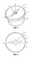
- FIG. 1is a perspective view of a protective sports helmet having a pad assembly.
- FIG. 2is a perspective view of a pad assembly.
- FIG. 3is a cross-sectional side view of the pad assembly of FIG. 2 .
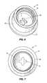
- FIG. 4is a perspective view of a retainer cap for use with the pad assembly of FIG. 2 .
- FIG. 5is a top view of the retainer cap of FIG. 4 .
- FIG. 6is another perspective view of the retainer cap of FIG. 4 .
- FIG. 7is a bottom view of the retainer cap of FIG. 4 .
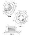
- FIG. 8is a perspective view of a valve retainer.
- FIG. 9is a bottom view of the valve retainer of FIG. 8 .
- FIG. 10is a side view of the valve retainer of FIG. 8 .
- FIG. 11is a perspective view of another valve retainer.
- FIG. 12is a perspective view of a protective sports helmet having a buckle assembly.
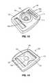
- FIG. 13is a bottom perspective view of a protective buckle cover and chin strap buckle.
- FIG. 14is a top perspective view of the protective buckle cover and chin strap buckle of FIG. 13 .
- FIG. 15is a perspective view of the protective buckle cover of FIG. 13 .
- FIG. 16is a top view of the protective buckle cover of FIG. 13 .
- FIG. 17is an end view of the protective buckle cover of FIG. 13 .
- FIG. 18is a side view of the protective buckle cover of FIG. 13 .
- FIGS. 1-3illustrate a protective sports helmet 5 having an internal pad assembly 16 that includes a plurality of pad assemblies 15 .
- the inventive pad assembly 15may be a jaw pad, a crown pad, an earflap pad and the like.
- an internal pad assembly 16may include one or more crown pads positioned in the top area of the protective sports helmet 5 , as well as a jaw pad and an earflap pad positioned on each side of the protective sports helmet 5 .
- FIGS. 4-7illustrate a cap 14 configured for threaded engagement with a valve retainer 10 (illustrated in FIGS. 8-11 ), wherein a pad member 11 , a pad housing 12 , the valve retainer 10 and the cap 14 comprise the inventive pad assembly 15 .
- a pad member 11are disposed within the pad housing 12 and the pad housing 12 is positioned within the interior of a helmet shell 7 .
- the valve retainer 10is sealingly connected to or integrated with the pad housing 12 .
- the valve retainer 10extends through an opening 9 in the helmet shell 7 , and the cap 14 is generally positioned within the opening 9 at the exterior of the protective sports helmet 5 .
- a valve body 18is received by the valve retainer 10 and includes a central opening 22 that is delimited by a sealing member 19 , such as a check valve, a self-sealing material and the like.
- the valve body 18is an elongated component that extends through at least a portion of the retainer 10 and allows inflation fluid, such as air and the like, to be compressed into or released from one or more bladders 13 associated with the pad assembly 15 of the helmet.
- the valve body 18may include an end portion 62 that engages the second side 30 of the valve retainer 10 to axially locate the valve body 18 with respect to the valve retainer 10 , the end portion 62 being in fluid communication with the bladder 13 . In the event that the pad assembly 15 lacks an inflatable bladder 13 , then the valve body 18 is omitted.
- the valve retainer 10includes a plate-like base 26 having a first side 28 and a second side 30 opposite the first side 28 .
- the base 26may be circular, oval and the like.
- the valve retainer 10also includes a boss 27 disposed on or integral with the first side 28 of the base 26 , the boss 27 configured to provide a standoff with an inner surface 8 of the helmet shell 7 .
- the boss 27may engage with an inner surface 8 of the helmet shell 7 that is disposed around the opening 9 , helping to stabilize the position of the valve retainer 10 within the opening 9 of the helmet shell 7 .
- the valve retainer 10also includes a projection 42 , preferably threaded, extending generally perpendicularly away from the first side 28 and substantially centered on the base 26 and the boss 27 .
- the projection 42includes external threads 46 and a substantially annular end surface 50 .
- the first side 28 , the end surface 50 , and the boss 27may all be substantially parallel with one another.
- the boss 27may extend in a convex shape from the first side 28 of the base 26 , such that the boss 27 is thicker near the projection 42 than it is near the outer edge of the boss 27 .
- At least a portion of the projection 42is configured to extend through the opening 9 provided in the helmet shell 7 .
- the entire projection 42is disposed within the opening 9 so that the projection 42 is protected by the helmet shell 7 .
- a central through bore 58 of the valve retainer 10extends through each of the threaded projection 42 , the boss 27 and the base 26 .
- the central through bore 58is sized and configured to receive a valve body 18 .
- the valve body 18may be press fit or otherwise secured (e.g., by adhesives) within the central through bore 58 .
- the base 26 of the valve retainer 10is sealingly coupled to an exterior of a corresponding bladder 13 in the pad assembly 12 such that at least the second side 30 of the base 26 is in fluid communication with the bladder 13 .
- the bladder 13may be RF welded, molded, overmolded and the like to the valve retainer 10 .
- the material of the bladder 13may be sealingly in contact with all of or a portion of the first side 28 of the base 26 , and not in contact with the boss 27 .
- the boss 27engages with the inner surface 8 of the helmet shell 7 surrounding the opening 9 , and the valve retainer 10 is substantially fixed with respect to the helmet shell 7 .
- a valve retainer 10 aincludes a plate-like base 26 a having a first side 28 a and a second side 30 a opposite the first side 28 a .
- the base 26 ais elongated and includes a pair of opposed distal ends 32 .
- a standoff 34extends generally perpendicularly away from the first side 28 a at each distal end 32 . End surfaces 38 of the standoffs 34 are configured for engagement with the inner surface 8 of the helmet shell 7 .
- the valve retainer 10 aalso includes a projection 42 a , preferably threaded, extending generally perpendicularly away from the first side 28 a and substantially centered on the base 26 a .
- the projection 42 aincludes external threads 46 a and a substantially annular end surface 50 a .
- the first side 28 a , the end surface 50 a , and the end surfaces 38are all substantially parallel with one another.
- a distance between the end surface 50 a and the first side 28 ais approximately two times a distance between the end surface 38 and the first side 28 a .
- the length of the projection 42 ais approximately twice the length of the standoffs 34 .
- An extent of the projection 42 ais configured to extend through the opening 9 provided in the helmet shell 7 .
- a central through bore 58 a of the valve retainer 10 aextends through each of the threaded projection 42 a and the base 26 a .
- the central through bore 58 ais sized and configured to receive the valve body 18 (not shown).
- the valve body 18may be press fit or otherwise secured (e.g., by adhesives) within the central through bore 58 a .
- the second side 30 a of the valve retainer 10 amay be sealingly coupled to an exterior of a corresponding bladder 13 in the pad assembly 15 such that the valve body 18 is in fluid communication with the bladder 13 .
- the valve retainer 10 acan be RF welded to the exterior of the corresponding bladder 13 .
- the cap 14includes a generally annular base portion 66 and a generally circular flange portion 70 coupled to one end of the base portion 66 and extending radially outward from the base portion 66 .
- the base portion 66is internally threaded 76 for engagement with the external threads 46 on the projection 42 .
- the base portion 66is configured to extend into the helmet shell opening 9 , which as discussed above is also occupied by the projection 42 of the retainer. In this regard, when the valve retainer 10 and cap 14 are installed in the helmet, portions of both the projection 42 of the valve retainer 10 and the base portion 66 of the cap 14 are threadedly engaged with one another while positioned in the shell opening 9 in the helmet shell 7 .
- the flange portion 70is configured to be received within a countersunk recess 6 provided on the external helmet shell surface 4 that is immediately adjacent to and surrounds the shell opening 9 .
- the flange portion 70rests on a shoulder defined by the differing diameters of the shell opening 9 and the countersunk recess 6 .
- the flange portion 70includes a top surface 74 and a manipulation recess 78 is formed in the flange portion 70 and recessed with respect to the top surface 74 .
- the top surface 74 of the flange portion 70is substantially flush with the outer surface 4 of the helmet shell 7 (see FIG. 3 ).
- the manipulation recess 78can be configured in a variety of ways for engagement with a standard manipulation device such as a screwdriver, star-bit, a coin, and the like.
- a standard manipulation devicesuch as a screwdriver, star-bit, a coin, and the like.
- the manipulation recess 78is generally in the shape of a cross, with one cross-member being longer than the other.
- the illustrated manipulation recess 78is thus manipulatable using a flat blade or Phillips type screwdriver.
- a through opening 82is also provided in the flange portion 70 and, in the illustrated configuration, extends from a floor 86 of the manipulation recess 78 and through the flange portion 70 .
- the through opening 82thus communicates with the interior of the base portion 66 of the cap 14 .
- the through opening 82is substantially aligned with the central opening 22 of the valve body 18 .
- the through opening 82is generally cross shaped, which can accommodate slight axial misalignment of the through opening 82 with respect to the central opening 22 .
- the through opening 82provides an access point for a standard inflation needle (not shown) to be inserted into the central opening 22 of the valve body 18 .
- inflation fluide.g., air
- the above described system of the valve retainer 10 and cap 14facilitates the attachment, adjustment and removal of the pad assembly 15 without damaging or detaching the valve retainer 10 or valve body 18 from the pad assembly 15 .
- the pad assembly 15is positioned such that the threaded projection 42 of the valve retainer 10 extends into the shell opening 9 .
- the base portion 66 of the cap 14is then inserted into the shell opening 9 and threadedly engaged with the threaded projection 42 .
- the base portion 66is positioned radially outward of the projection 42 and the valve body 18 .
- the cap 14can initially be finger tightened and then, as the components begin to draw snug, a tool, such as a screwdriver, can be used to fully tighten the cap 14 and the valve retainer 10 .
- Disassemblyis the reverse operation, whereby the cap 14 is loosened and removed from the shell opening 9 and the valve retainer 10 can then be withdrawn from the internal side of the shell opening 9 .
- FIG. 12illustrates a protective sports helmet 105 having a buckle assembly 108 that may be used, for example, to secure a chin strap 107 to the protective sports helmet 105 .
- the buckle assembly 108includes a protective cover 110 and buckle 114 that is inserted into or otherwise at least partially surrounded by the cover 110 .
- the illustrated buckle 114is formed of metal and includes a central body portion 118 having a first strap opening 122 and a second strap opening 126 formed therein.
- the first strap opening 122 and second strap opening 126further have strap securing portions 122 a , 126 a that include a plurality of teeth that engage an extent of a chin strap to help secure the buckle 114 in a fixed location relative to the chin strap.
- the buckle 114includes a generally rectangular perimeter defining an outer edge that is received by the cover 110 , as discussed below.
- an attachment portion 130is provided on the buckle 114 to fasten the buckle 114 and the chin strap attached to the buckle 114 to the protective helmet.
- the attachment portion 130includes a central rivet 134 and in the illustrated configuration forms the female component of a snap assembly, although the attachment portion 130 may also form the male component of a snap assembly, or may be configured as one portion of other known attachment types.
- the cover 110is formed of a relatively soft, flexible material and in some configurations, the buckle 114 may be removably inserted into the cover 110 .
- the buckle cover 110includes a top wall 138 , a bottom wall 142 , and sidewalls 146 a , 146 b , 146 c , 146 d extending between the top wall 138 and the bottom wall 142 .
- the cover 110is generally rectangular and includes a longitudinal axis Lo and a lateral axis La.
- the sidewalls 146 a , 146 bextend in the longitudinal axis Lo and are therefore longer than the sidewalls 146 c , 146 d , which extend in the lateral direction La.
- the top wall 138defines a generally rectangular top opening 150 .
- the top opening 150is sized and configured to receive a portion of the chin strap that extends over the central body portion 118 and between the first and second chin strap openings 122 , 126 of the buckle 114 .
- the top opening 150includes first and second laterally extending edges 152 a , 152 b .
- the bottom wall 142defines a centrally located attachment opening 154 that is aligned with and that receives the attachment portion 130 of the buckle 114 .
- the attachment opening 154includes a pair of diametrically opposed first arc segment edges 158 that extend generally in the lateral direction La and that have a first diameter, and a pair of diametrically opposed second arc segment edges 162 that extend generally in the longitudinal direction Lo and that have a second diameter greater than the first diameter. Laterally extending straight edge segments 166 extend between respective ends of the first arc segment edges 158 and second arc segment edges 162 . In some configurations, including configurations where the cover 110 is removably securable to the buckle 114 , the larger diameter second arc segment edges 162 facilitate insertion and removal of the attachment portion 130 with respect to the attachment opening 154 . In other configurations, the attachment opening 154 may be a substantially uniform circle.
- the bottom wall 142also defines a first strap opening 170 and a second strap opening 174 .
- the first and second strap openings 170 , 174are substantially rectangular and are positioned for alignment with the first and second strap openings 122 , 126 in the buckle 114 when the buckle 114 is inserted into the cover 110 .
- the first and second strap openings 170 , 174have a length in the lateral direction La of the cover 110 that is substantially equal to a width (also in the lateral direction La) of the top opening 150 .
- the length of the strap openings 170 , 174 and width of the top opening 150generally are selected to correspond to the width of the chin strap to which the buckle 114 and cover 110 are to be attached.
- FIG. 1The length of the strap openings 170 , 174 and width of the top opening 150 generally are selected to correspond to the width of the chin strap to which the buckle 114 and cover 110 are to be attached.
- the edges 152 a , 152 b of the top wall 138are inwardly spaced with respect to the outer, laterally extending edges of the first and second strap openings 170 , 174 .
- the top wall 138includes overhanging portions 178 that extend above the first and second strap openings 170 , 174 .
- the cover 110defines a continuous channel 182 having a substantially C-shaped cross section extending around a periphery of the cover 110 .
- the channel 182is configured to receive and surround the perimeter and outer edge of the buckle 114 .
- the channel 182is cooperatively defined by the top wall 138 , the bottom wall 142 , and the side walls 146 a , 146 b , 146 c , 146 d .
- the channel 182includes four channel segments 186 a , 186 b , 186 c , 186 d with each segment associated with a respective one of the side walls 146 a , 146 b , 146 c , 146 d .
- Segments 186 a and 186 bcomprise side segments and extend in the longitudinal direction Lo.
- segment 186 a , 186 bare generally outwardly bowed such that the middle portions of the segments 186 a , 186 b are laterally separated by a greater distance than the end portions of the segments 186 a , 186 b .
- Segments 186 c and 186 dcomprise end segments and extend in the lateral direction La. As viewed from above ( FIG. 16 ) the segments 186 c , 186 d are substantially straight and parallel with one another.
- the segments 186 a and 186 bare uniformly curved such that the top wall 38 has a convex profile while the bottom wall 142 has a concave profile.
- the uniform curvatureextends into the segments 186 c , 186 d such that, as viewed from the side ( FIG. 18 ), the segments 186 c , 186 d are set at an angle or inclined in the longitudinal direction Lo, with the outermost portions of the segments 186 c , 186 d being at a lower elevation than the inner portions of the segments 186 c , 186 d.
- the segments 186 a , 186 bare set at an angle or inclined in the lateral direction La such that the laterally outer portions of the segments 186 a , 186 b are at a higher elevation than the laterally inner portions of the segments 186 a , 186 b .
- portions of the top wall 138 that define the segments 186 a , 186 bare also inclined such that the laterally outer edges of the top wall 138 are at a higher elevation than the laterally inner edges of the top wall 138 .
- the chin strap and the cover 110cooperate to substantially completely cover the body portion 118 of the buckle 114 . More specifically, the outer portions of the buckle 114 are received within the channel 182 , and the central area of the body portion 118 , e.g., where the central rivet 134 is located, is covered by the chin strap. In this regard there is little, if any, exposed buckle surface present on the exterior of the helmet when the buckle 114 is attached to the helmet to secure the chin strap.
- the cover 110may be easily removed and replaced by flexing the top wall 138 to withdraw the buckle 114 from the channel 182 and then extracting the attachment portion 130 from the attachment opening 154 .
- the cover 110may be formed of a rubber material that can be colored to match or compliment the color of the chin strap, the face mask, and/or the helmet, thereby increasing the aesthetic appeal of the buckle assembly.
- valve retainermay be integrally formed with a liner portion of the pad assembly. Accordingly, the invention is therefore to be limited only by the scope of the appended claims. While the specific embodiments have been illustrated and described, numerous modifications come to mind without significantly departing from the spirit of the invention, and the scope of protection is only limited by the scope of the accompanying claims.
Landscapes
- Health & Medical Sciences (AREA)
- General Health & Medical Sciences (AREA)
- Physical Education & Sports Medicine (AREA)
- Helmets And Other Head Coverings (AREA)
Abstract
Description
Claims (21)
Priority Applications (4)
| Application Number | Priority Date | Filing Date | Title |
|---|---|---|---|
| US14/179,333US9770060B2 (en) | 2013-02-12 | 2014-02-12 | Pad assemblies for a protective sports helmet |
| US15/714,422US10624407B2 (en) | 2013-02-12 | 2017-09-25 | Pad assemblies for a protective sports helmet |
| US16/853,387US11399588B2 (en) | 2013-02-12 | 2020-04-20 | Pad assemblies for a protective sports helmet |
| US17/878,199US20230137144A1 (en) | 2013-02-12 | 2022-08-01 | Pad assemblies for a protective sports helmet |
Applications Claiming Priority (3)
| Application Number | Priority Date | Filing Date | Title |
|---|---|---|---|
| US201361763762P | 2013-02-12 | 2013-02-12 | |
| US201361763760P | 2013-02-12 | 2013-02-12 | |
| US14/179,333US9770060B2 (en) | 2013-02-12 | 2014-02-12 | Pad assemblies for a protective sports helmet |
Related Child Applications (1)
| Application Number | Title | Priority Date | Filing Date |
|---|---|---|---|
| US15/714,422ContinuationUS10624407B2 (en) | 2013-02-12 | 2017-09-25 | Pad assemblies for a protective sports helmet |
Publications (2)
| Publication Number | Publication Date |
|---|---|
| US20140223643A1 US20140223643A1 (en) | 2014-08-14 |
| US9770060B2true US9770060B2 (en) | 2017-09-26 |
Family
ID=51296355
Family Applications (3)
| Application Number | Title | Priority Date | Filing Date |
|---|---|---|---|
| US14/179,333Active2035-03-03US9770060B2 (en) | 2013-02-12 | 2014-02-12 | Pad assemblies for a protective sports helmet |
| US15/714,422Active2034-05-25US10624407B2 (en) | 2013-02-12 | 2017-09-25 | Pad assemblies for a protective sports helmet |
| US16/853,387ActiveUS11399588B2 (en) | 2013-02-12 | 2020-04-20 | Pad assemblies for a protective sports helmet |
Family Applications After (2)
| Application Number | Title | Priority Date | Filing Date |
|---|---|---|---|
| US15/714,422Active2034-05-25US10624407B2 (en) | 2013-02-12 | 2017-09-25 | Pad assemblies for a protective sports helmet |
| US16/853,387ActiveUS11399588B2 (en) | 2013-02-12 | 2020-04-20 | Pad assemblies for a protective sports helmet |
Country Status (1)
| Country | Link |
|---|---|
| US (3) | US9770060B2 (en) |
Cited By (21)
| Publication number | Priority date | Publication date | Assignee | Title |
|---|---|---|---|---|
| US20170196294A1 (en)* | 2016-01-08 | 2017-07-13 | VICIS, Inc. | Removing pads within a helmet contacting a wearer's head while minimizing movement of the wearer's head during removal |
| US20180007992A1 (en)* | 2013-02-12 | 2018-01-11 | Riddell, Inc. | Pad assemblies for a protective sports helmet |
| US10258100B1 (en) | 2012-06-18 | 2019-04-16 | Kranos Ip Corporation | Football helmet with raised plateau |
| US10285466B2 (en) | 2010-07-22 | 2019-05-14 | Kranos Ip Corporation | Football helmet with shell section defined by a non-linear channel |
| USD850013S1 (en) | 2017-07-20 | 2019-05-28 | Riddell, Inc. | Internal padding assembly of a protective sports helmet |
| USD850011S1 (en) | 2017-07-20 | 2019-05-28 | Riddell, Inc. | Internal padding assembly of a protective sports helmet |
| USD850012S1 (en) | 2017-07-20 | 2019-05-28 | Riddell, Inc. | Internal padding assembly of a protective sports helmet |
| US10362829B2 (en) | 2013-12-06 | 2019-07-30 | Bell Sports, Inc. | Multi-layer helmet and method for making the same |
| US10582737B2 (en) | 2013-02-12 | 2020-03-10 | Riddell, Inc. | Football helmet with impact attenuation system |
| US10721987B2 (en) | 2014-10-28 | 2020-07-28 | Bell Sports, Inc. | Protective helmet |
| US10780338B1 (en) | 2016-07-20 | 2020-09-22 | Riddell, Inc. | System and methods for designing and manufacturing bespoke protective sports equipment |
| US10948898B1 (en) | 2013-01-18 | 2021-03-16 | Bell Sports, Inc. | System and method for custom forming a protective helmet for a customer's head |
| USD927084S1 (en) | 2018-11-22 | 2021-08-03 | Riddell, Inc. | Pad member of an internal padding assembly of a protective sports helmet |
| US11076646B2 (en) | 2011-01-24 | 2021-08-03 | Guardian Athletics, Llc | Athletic collar |
| USD927078S1 (en)* | 2014-02-12 | 2021-08-03 | Riddell, Inc. | Football helmet |
| US11167198B2 (en) | 2018-11-21 | 2021-11-09 | Riddell, Inc. | Football helmet with components additively manufactured to manage impact forces |
| US11330857B2 (en)* | 2017-10-10 | 2022-05-17 | Wilcox Industries Corp. | Helmet mount interface apparatuses and methods |
| US11399589B2 (en) | 2018-08-16 | 2022-08-02 | Riddell, Inc. | System and method for designing and manufacturing a protective helmet tailored to a selected group of helmet wearers |
| US11503872B2 (en) | 2011-09-09 | 2022-11-22 | Riddell, Inc. | Protective sports helmet |
| USD980538S1 (en)* | 2019-07-01 | 2023-03-07 | Vicis Ip, Llc | Perforated helmet |
| US11606997B2 (en) | 2017-10-06 | 2023-03-21 | Wilcox Industries Corp. | Modular helmet interface with threaded insert |
Families Citing this family (14)
| Publication number | Priority date | Publication date | Assignee | Title |
|---|---|---|---|---|
| US9943746B2 (en)* | 2010-02-26 | 2018-04-17 | The Holding Company, Llc | Protective headgear with impact diffusion |
| US20120304367A1 (en)* | 2010-02-26 | 2012-12-06 | Thl Holding Company, Llc | Protective helmet |
| US11464271B2 (en)* | 2012-05-14 | 2022-10-11 | William A. Jacob | Energy dissipating helmet |
| US11812813B1 (en) | 2013-01-31 | 2023-11-14 | Michael L. Fogg | Demi-helmet and mask combination providing facial impact protection and entirely unobstructed views in both forward and peripheral directions, and associated methods |
| US20230137144A1 (en)* | 2013-02-12 | 2023-05-04 | Riddell, Inc. | Pad assemblies for a protective sports helmet |
| USD752821S1 (en)* | 2014-02-12 | 2016-03-29 | Riddell, Inc. | Football helmet |
| USD752823S1 (en)* | 2014-02-12 | 2016-03-29 | Ridell, Inc. | Football helmet |
| USD764716S1 (en)* | 2014-02-12 | 2016-08-23 | Riddell, Inc. | Football helmet |
| US10219572B1 (en)* | 2014-03-10 | 2019-03-05 | John E. Whitcomb | Baseball cap having impact protection |
| AU2015240886A1 (en) | 2014-04-01 | 2016-10-06 | Bell Sports, Inc. | Locking liner for helmet |
| USD932108S1 (en)* | 2019-01-04 | 2021-09-28 | Vicis Ip, Llc | Athletic helmet facemask |
| USD927073S1 (en)* | 2019-04-16 | 2021-08-03 | Safer Sports, LLC | Football helmet |
| US11918070B2 (en) | 2020-01-03 | 2024-03-05 | Vicis Ip, Llc | Facemask system |
| GB2597534B (en)* | 2020-07-28 | 2025-09-17 | Strategic Sports Ltd | Improvements in or relating to Helmets |
Citations (40)
| Publication number | Priority date | Publication date | Assignee | Title |
|---|---|---|---|---|
| US3153973A (en)* | 1962-03-06 | 1964-10-27 | Michael T Marietta | Pad for shielding an exposed end of a fastener |
| US3197784A (en) | 1962-09-04 | 1965-08-03 | Carlisle Res And Dev Corp | Segmented helmet |
| US3274613A (en)* | 1964-02-03 | 1966-09-27 | Theo J Sowle | Pivoting face guard assembly |
| US3568210A (en)* | 1968-10-10 | 1971-03-09 | Michael T Marietta | Protective headgear |
| US3609764A (en)* | 1969-03-20 | 1971-10-05 | Riddell | Energy absorbing and sizing means for helmets |
| US3713640A (en)* | 1970-07-27 | 1973-01-30 | Riddell | Energy absorbing and sizing means for helmets |
| US3720955A (en)* | 1971-11-26 | 1973-03-20 | Questor Corp | Football helmet |
| US3761959A (en)* | 1971-12-27 | 1973-10-02 | F Dunning | Inflatable padding for football helmet or the like |
| US3785395A (en)* | 1972-01-19 | 1974-01-15 | B Andreasson | Air valves |
| US3872511A (en)* | 1974-03-11 | 1975-03-25 | Larcher Angelo C | Protective headgear |
| US4282610A (en)* | 1978-01-16 | 1981-08-11 | The Kendall Company | Protective headgear |
| US4287613A (en)* | 1979-07-09 | 1981-09-08 | Riddell, Inc. | Headgear with energy absorbing and sizing means |
| US4363140A (en)* | 1981-07-27 | 1982-12-14 | Correale James V | Football helmet face guard |
| US4370759A (en)* | 1981-03-17 | 1983-02-01 | Pro-Line, Inc. | Face guard mount for helmets |
| US4478587A (en)* | 1982-11-16 | 1984-10-23 | Mackal Glenn H | Inflatable boat valve and mounting therefor |
| US4724549A (en)* | 1984-12-11 | 1988-02-16 | Airsorb Pty. Ltd. | Protective helmet and locking means |
| US4853980A (en)* | 1984-12-21 | 1989-08-08 | Sonda S.R.L. | Protective buffer padding element |
| US5014365A (en)* | 1989-01-23 | 1991-05-14 | Maxpro Helmets, Inc. | Gas-fitted protective helmet |
| US5031246A (en)* | 1990-03-02 | 1991-07-16 | Kronenberger Robert A | Headwear with size adjustment feature |
| US5175889A (en)* | 1990-08-29 | 1993-01-05 | Riddell, Inc. | Inflatable liner for protective headgear |
| US5941272A (en)* | 1996-12-04 | 1999-08-24 | Imaginair, Inc. | Three way universal valve |
| US6073271A (en)* | 1999-02-09 | 2000-06-13 | Adams Usa, Inc. | Football helmet with inflatable liner |
| US6079053A (en)* | 1999-04-27 | 2000-06-27 | Clover, Jr.; James B. | Helmet facemask attachment assembly |
| US6089251A (en)* | 1998-01-19 | 2000-07-18 | Zodiac International | Pneumatic valve |
| US6154889A (en) | 1998-02-20 | 2000-12-05 | Team Wendy, Llc | Protective helmet |
| US20010034895A1 (en)* | 2000-05-01 | 2001-11-01 | Shoei, Co., Ltd. | Inside pad for helmet and helmet using this inside pad |
| US6785985B2 (en)* | 2002-07-02 | 2004-09-07 | Reebok International Ltd. | Shoe having an inflatable bladder |
| US6934971B2 (en)* | 2002-05-01 | 2005-08-30 | Riddell, Inc. | Football helmet |
| US20080250550A1 (en)* | 2007-04-16 | 2008-10-16 | Vittorio Bologna | Sports helmet with quick-release faceguard connector and adjustable internal pad element |
| US20090031479A1 (en) | 2007-08-02 | 2009-02-05 | Dr. Gus A. Rush Iii | Athletic helmet |
| US20090222964A1 (en)* | 2007-01-26 | 2009-09-10 | Wiles William A | Advanced Combat Helmet (ACH) system replacement padding system |
| US7900279B2 (en)* | 2006-09-08 | 2011-03-08 | Riddell, Inc. | Sports helmet with clamp for securing a chin protector |
| US20110131695A1 (en)* | 2009-12-09 | 2011-06-09 | Maddux Larry E | TPU/Foam Jaw Pad |
| US20110271428A1 (en) | 2007-04-16 | 2011-11-10 | Chris Withnall | Protective sports helmet |
| US20120079646A1 (en)* | 2010-10-05 | 2012-04-05 | Guillaume Belanger | Hockey helmet with readily removable earpieces |
| US8328159B2 (en)* | 2006-10-25 | 2012-12-11 | Lee Ti-Tien | Vacuum valve device for bag |
| US20130061375A1 (en)* | 2011-09-09 | 2013-03-14 | Riddell, Inc. | Protective sports helmet |
| US8544117B2 (en)* | 2011-07-13 | 2013-10-01 | Kranos Ip Corporation | Ventilated air liner for a helmet |
| US20140033402A1 (en)* | 2012-08-01 | 2014-02-06 | Salomon S.A.S. | Protective helmet |
| US20160051013A1 (en)* | 2014-03-14 | 2016-02-25 | Bruce James Mitchell, JR. | Strap latching device |
Family Cites Families (54)
| Publication number | Priority date | Publication date | Assignee | Title |
|---|---|---|---|---|
| US1172406A (en)* | 1915-09-16 | 1916-02-22 | Thomas B Taylor | Hollow sheet-metal bolt. |
| US2264931A (en)* | 1939-05-31 | 1941-12-02 | Chichester-Mi Herbert G Wright | Helmet having anticoncussion pads |
| US3186004A (en) | 1962-06-07 | 1965-06-01 | Richard E Carlini | Protective helmet |
| US3500472A (en) | 1968-05-13 | 1970-03-17 | Joseph D Castellani | Football and baseball equipment |
| US3600714A (en) | 1969-03-19 | 1971-08-24 | Hop N Gator Inc | Hydraulic helmet |
| US3849801A (en) | 1972-12-20 | 1974-11-26 | Medalist Ind Inc | Protective gear with hydraulic liner |
| US3994020A (en) | 1975-06-05 | 1976-11-30 | The Kendall Company | Protective helmet with liner means |
| DE2526336A1 (en) | 1975-06-12 | 1976-12-16 | Kalman Gyoery | USE FOR SAFETY HELMETS, IN PARTICULAR MOTORCYCLE HELMETS |
| US3999220A (en) | 1976-04-22 | 1976-12-28 | Keltner Raymond O | Air-cushioned protective gear |
| US4566137A (en) | 1984-01-20 | 1986-01-28 | Gooding Elwyn R | Inflatable baffled liner for protective headgear and other protective equipment |
| US5263203A (en) | 1991-10-07 | 1993-11-23 | Riddell, Inc. | Integrated pump mechanism and inflatable liner for protective |
| DE4409839C2 (en) | 1994-03-22 | 1996-05-02 | Oped Gmbh Orthopaedische Produ | Hard hat |
| US5774901A (en)* | 1996-08-15 | 1998-07-07 | Bell Sports, Inc. | Sport helmet retention apparatus |
| US5734994A (en) | 1997-02-06 | 1998-04-07 | M.P.H. Associates, Inc. | Ventilated safety helmet with progressively crushable liner |
| US6298483B1 (en) | 1997-09-03 | 2001-10-09 | Paul Schiebl | Protective headgear and chin pad |
| US6261042B1 (en)* | 1998-11-03 | 2001-07-17 | Textron Inc. | Quick-release fastener system |
| US6226801B1 (en)* | 1999-02-09 | 2001-05-08 | Adams Usa, Inc. | Football helmet having a removable inflatable liner and a method for making the same |
| US6219850B1 (en) | 1999-06-04 | 2001-04-24 | Lexington Safety Products, Inc. | Helmet |
| US6178560B1 (en) | 1999-06-04 | 2001-01-30 | Southern Impact Research Center, Llc | Helmet fitting system |
| US6530092B2 (en)* | 2001-05-09 | 2003-03-11 | Southern Impact Research Center, Llc | Fitting and comfort system with inflatable liner for helmet |
| CA2422392A1 (en) | 2002-03-12 | 2003-09-12 | Bombardier Inc. | Cold-weather helmet with breathing mask breathing air from inside the helmet |
| US20030188375A1 (en) | 2002-04-08 | 2003-10-09 | Reginald Wilson | Helmet device with side configured peripheral viewing portions |
| US7089602B2 (en) | 2003-06-30 | 2006-08-15 | Srikrishna Talluri | Multi-layered, impact absorbing, modular helmet |
| US7328462B1 (en) | 2004-02-17 | 2008-02-12 | Albert E Straus | Protective helmet |
| US8256147B2 (en) | 2004-11-22 | 2012-09-04 | Frampton E. Eliis | Devices with internal flexibility sipes, including siped chambers for footwear |
| US7774866B2 (en) | 2006-02-16 | 2010-08-17 | Xenith, Llc | Impact energy management method and system |
| JP4584880B2 (en)* | 2006-07-27 | 2010-11-24 | スミダコーポレーション株式会社 | Inverter circuit |
| US7917972B1 (en) | 2007-07-25 | 2011-04-05 | Body Armour Technology, Llc | Inflatable air recoil suppressor |
| US8418270B2 (en) | 2007-12-12 | 2013-04-16 | Sport Maska Inc. | Protective helmet |
| GB0800971D0 (en) | 2008-01-18 | 2008-02-27 | Ayrtek Ltd | Sports helmet |
| GB2457077A (en) | 2008-02-01 | 2009-08-05 | Julian Joshua Preston-Powers | Cooling system for headwear |
| US20100180362A1 (en) | 2009-01-16 | 2010-07-22 | The Burton Corporation | Adjustable fitting helmet |
| US8739317B2 (en) | 2010-04-19 | 2014-06-03 | Patrick Abernethy | Rebound-dampening headgear liners with positioning feature |
| US20120017358A1 (en) | 2010-07-22 | 2012-01-26 | Wingo-Princip Management LLC | Protective helmet |
| US8549671B2 (en)* | 2011-01-06 | 2013-10-08 | Bell Sports, Inc. | Helmet having magnetically coupled cheek pads |
| WO2012148582A2 (en) | 2011-04-29 | 2012-11-01 | Roho, Inc. | Multilayer impact attenuating insert for headgear |
| US9032558B2 (en) | 2011-05-23 | 2015-05-19 | Lionhead Helmet Intellectual Properties, Lp | Helmet system |
| US8429766B2 (en)* | 2011-09-09 | 2013-04-30 | Alvin J. Halfaker | Helmet with embedded sound suppression ear cups |
| US8814150B2 (en) | 2011-12-14 | 2014-08-26 | Xenith, Llc | Shock absorbers for protective body gear |
| CA2770713A1 (en) | 2012-03-05 | 2013-09-05 | Paul L. Cote | Helmet |
| US20130232668A1 (en) | 2012-03-06 | 2013-09-12 | Loubert S. Suddaby | Helmet with multiple protective zones |
| US9380823B2 (en) | 2012-04-27 | 2016-07-05 | William R. Johnson | Electronically controlled impact attenuating fluid containing cells for helmets |
| EP2884863B1 (en) | 2012-06-11 | 2020-08-05 | Tate Technology LLC | Enhanced recoil attenuating safety helmet |
| BR112015016922B1 (en) | 2013-01-18 | 2022-09-13 | Windpact, Inc | APPARATUS FOR IMPACT ABSORPTION |
| US20140208486A1 (en) | 2013-01-25 | 2014-07-31 | Wesley W.O. Krueger | Impact reduction helmet |
| US9770060B2 (en)* | 2013-02-12 | 2017-09-26 | Riddell, Inc. | Pad assemblies for a protective sports helmet |
| US20160053843A1 (en) | 2013-03-21 | 2016-02-25 | University Of Florida Research Foundation, Inc. | Device for absorbing impact |
| US9841075B2 (en) | 2013-10-11 | 2017-12-12 | Rousseau Research, Inc. | Protective athletic equipment |
| US9408423B2 (en) | 2014-09-25 | 2016-08-09 | David A. Guerra | Impact reducing sport equipment |
| US9918507B2 (en)* | 2014-11-25 | 2018-03-20 | Charles Eaton | Protective helmet |
| WO2017120374A1 (en)* | 2016-01-08 | 2017-07-13 | VICIS, Inc. | Removing pads within a helmet contacting a wearer's head while minimizing movement of the wearer's head during removal |
| US11291264B2 (en)* | 2016-04-08 | 2022-04-05 | Schutt Sports Ip, Llc | Football helmet shell |
| US20180343952A1 (en)* | 2017-06-05 | 2018-12-06 | Headnorth Inc. | Shock absorbing system for protective equipment and devices therefor |
| US20190174859A1 (en)* | 2017-12-07 | 2019-06-13 | Rawlings Sporting Goods Company, Inc. | Helmet liner |
- 2014
- 2014-02-12USUS14/179,333patent/US9770060B2/enactiveActive
- 2017
- 2017-09-25USUS15/714,422patent/US10624407B2/enactiveActive
- 2020
- 2020-04-20USUS16/853,387patent/US11399588B2/enactiveActive
Patent Citations (41)
| Publication number | Priority date | Publication date | Assignee | Title |
|---|---|---|---|---|
| US3153973A (en)* | 1962-03-06 | 1964-10-27 | Michael T Marietta | Pad for shielding an exposed end of a fastener |
| US3197784A (en) | 1962-09-04 | 1965-08-03 | Carlisle Res And Dev Corp | Segmented helmet |
| US3274613A (en)* | 1964-02-03 | 1966-09-27 | Theo J Sowle | Pivoting face guard assembly |
| US3568210A (en)* | 1968-10-10 | 1971-03-09 | Michael T Marietta | Protective headgear |
| US3609764A (en)* | 1969-03-20 | 1971-10-05 | Riddell | Energy absorbing and sizing means for helmets |
| US3713640A (en)* | 1970-07-27 | 1973-01-30 | Riddell | Energy absorbing and sizing means for helmets |
| US3720955A (en)* | 1971-11-26 | 1973-03-20 | Questor Corp | Football helmet |
| US3761959A (en)* | 1971-12-27 | 1973-10-02 | F Dunning | Inflatable padding for football helmet or the like |
| US3785395A (en)* | 1972-01-19 | 1974-01-15 | B Andreasson | Air valves |
| US3872511A (en)* | 1974-03-11 | 1975-03-25 | Larcher Angelo C | Protective headgear |
| US4282610A (en)* | 1978-01-16 | 1981-08-11 | The Kendall Company | Protective headgear |
| US4287613A (en)* | 1979-07-09 | 1981-09-08 | Riddell, Inc. | Headgear with energy absorbing and sizing means |
| US4370759A (en)* | 1981-03-17 | 1983-02-01 | Pro-Line, Inc. | Face guard mount for helmets |
| US4363140A (en)* | 1981-07-27 | 1982-12-14 | Correale James V | Football helmet face guard |
| US4478587A (en)* | 1982-11-16 | 1984-10-23 | Mackal Glenn H | Inflatable boat valve and mounting therefor |
| US4724549A (en)* | 1984-12-11 | 1988-02-16 | Airsorb Pty. Ltd. | Protective helmet and locking means |
| US4853980A (en)* | 1984-12-21 | 1989-08-08 | Sonda S.R.L. | Protective buffer padding element |
| US5014365A (en)* | 1989-01-23 | 1991-05-14 | Maxpro Helmets, Inc. | Gas-fitted protective helmet |
| US5031246A (en)* | 1990-03-02 | 1991-07-16 | Kronenberger Robert A | Headwear with size adjustment feature |
| US5175889A (en)* | 1990-08-29 | 1993-01-05 | Riddell, Inc. | Inflatable liner for protective headgear |
| US5941272A (en)* | 1996-12-04 | 1999-08-24 | Imaginair, Inc. | Three way universal valve |
| US6089251A (en)* | 1998-01-19 | 2000-07-18 | Zodiac International | Pneumatic valve |
| US6154889A (en) | 1998-02-20 | 2000-12-05 | Team Wendy, Llc | Protective helmet |
| US6073271A (en)* | 1999-02-09 | 2000-06-13 | Adams Usa, Inc. | Football helmet with inflatable liner |
| US6079053A (en)* | 1999-04-27 | 2000-06-27 | Clover, Jr.; James B. | Helmet facemask attachment assembly |
| US20010034895A1 (en)* | 2000-05-01 | 2001-11-01 | Shoei, Co., Ltd. | Inside pad for helmet and helmet using this inside pad |
| US6421841B2 (en)* | 2000-05-01 | 2002-07-23 | Shoei Co., Ltd. | Inside pad for helmet and helmet using this inside pad |
| US6934971B2 (en)* | 2002-05-01 | 2005-08-30 | Riddell, Inc. | Football helmet |
| US6785985B2 (en)* | 2002-07-02 | 2004-09-07 | Reebok International Ltd. | Shoe having an inflatable bladder |
| US7900279B2 (en)* | 2006-09-08 | 2011-03-08 | Riddell, Inc. | Sports helmet with clamp for securing a chin protector |
| US8328159B2 (en)* | 2006-10-25 | 2012-12-11 | Lee Ti-Tien | Vacuum valve device for bag |
| US20090222964A1 (en)* | 2007-01-26 | 2009-09-10 | Wiles William A | Advanced Combat Helmet (ACH) system replacement padding system |
| US20110271428A1 (en) | 2007-04-16 | 2011-11-10 | Chris Withnall | Protective sports helmet |
| US20080250550A1 (en)* | 2007-04-16 | 2008-10-16 | Vittorio Bologna | Sports helmet with quick-release faceguard connector and adjustable internal pad element |
| US20090031479A1 (en) | 2007-08-02 | 2009-02-05 | Dr. Gus A. Rush Iii | Athletic helmet |
| US20110131695A1 (en)* | 2009-12-09 | 2011-06-09 | Maddux Larry E | TPU/Foam Jaw Pad |
| US20120079646A1 (en)* | 2010-10-05 | 2012-04-05 | Guillaume Belanger | Hockey helmet with readily removable earpieces |
| US8544117B2 (en)* | 2011-07-13 | 2013-10-01 | Kranos Ip Corporation | Ventilated air liner for a helmet |
| US20130061375A1 (en)* | 2011-09-09 | 2013-03-14 | Riddell, Inc. | Protective sports helmet |
| US20140033402A1 (en)* | 2012-08-01 | 2014-02-06 | Salomon S.A.S. | Protective helmet |
| US20160051013A1 (en)* | 2014-03-14 | 2016-02-25 | Bruce James Mitchell, JR. | Strap latching device |
Cited By (46)
| Publication number | Priority date | Publication date | Assignee | Title |
|---|---|---|---|---|
| US10470516B2 (en) | 2010-07-22 | 2019-11-12 | Kranos Ip Corporation | Impact attenuation system for a protective helmet |
| US10285466B2 (en) | 2010-07-22 | 2019-05-14 | Kranos Ip Corporation | Football helmet with shell section defined by a non-linear channel |
| US10736372B2 (en) | 2010-07-22 | 2020-08-11 | Kanos Ip Corporation | Impact attenuation system for a protective helmet |
| US10470515B2 (en) | 2010-07-22 | 2019-11-12 | Kranos Ip Corporation | Football helmet with pressable front section |
| US10357075B2 (en) | 2010-07-22 | 2019-07-23 | Kranos Ip Corporation | Impact attenuation system for a protective helmet |
| US10470514B2 (en) | 2010-07-22 | 2019-11-12 | Kranos Ip Corporation | Football helmet with movable shell segment |
| US10448691B2 (en) | 2010-07-22 | 2019-10-22 | Kranos Ip Corporation | Football helmet with movable flexible section |
| US11076646B2 (en) | 2011-01-24 | 2021-08-03 | Guardian Athletics, Llc | Athletic collar |
| US11503872B2 (en) | 2011-09-09 | 2022-11-22 | Riddell, Inc. | Protective sports helmet |
| US10258100B1 (en) | 2012-06-18 | 2019-04-16 | Kranos Ip Corporation | Football helmet with raised plateau |
| US10376011B2 (en) | 2012-06-18 | 2019-08-13 | Kranos Ip Corporation | Football helmet with raised plateau |
| US11419383B2 (en) | 2013-01-18 | 2022-08-23 | Riddell, Inc. | System and method for custom forming a protective helmet for a customer's head |
| US10948898B1 (en) | 2013-01-18 | 2021-03-16 | Bell Sports, Inc. | System and method for custom forming a protective helmet for a customer's head |
| US11889883B2 (en) | 2013-01-18 | 2024-02-06 | Bell Sports, Inc. | System and method for forming a protective helmet for a customer's head |
| US11910859B2 (en) | 2013-02-12 | 2024-02-27 | Riddell, Inc. | Football helmet with impact attenuation system |
| US10582737B2 (en) | 2013-02-12 | 2020-03-10 | Riddell, Inc. | Football helmet with impact attenuation system |
| US10624407B2 (en)* | 2013-02-12 | 2020-04-21 | Riddell, Inc. | Pad assemblies for a protective sports helmet |
| US11399588B2 (en) | 2013-02-12 | 2022-08-02 | Riddell, Inc. | Pad assemblies for a protective sports helmet |
| US20180007992A1 (en)* | 2013-02-12 | 2018-01-11 | Riddell, Inc. | Pad assemblies for a protective sports helmet |
| US11871809B2 (en) | 2013-12-06 | 2024-01-16 | Bell Sports, Inc. | Multi-layer helmet and method for making the same |
| US10362829B2 (en) | 2013-12-06 | 2019-07-30 | Bell Sports, Inc. | Multi-layer helmet and method for making the same |
| US11291263B2 (en) | 2013-12-06 | 2022-04-05 | Bell Sports, Inc. | Multi-layer helmet and method for making the same |
| USD980537S1 (en)* | 2014-02-12 | 2023-03-07 | Riddell, Inc. | Football helmet |
| USD927078S1 (en)* | 2014-02-12 | 2021-08-03 | Riddell, Inc. | Football helmet |
| US11638457B2 (en) | 2014-10-28 | 2023-05-02 | Bell Sports, Inc. | Protective helmet |
| US10721987B2 (en) | 2014-10-28 | 2020-07-28 | Bell Sports, Inc. | Protective helmet |
| US20170196294A1 (en)* | 2016-01-08 | 2017-07-13 | VICIS, Inc. | Removing pads within a helmet contacting a wearer's head while minimizing movement of the wearer's head during removal |
| US11213736B2 (en) | 2016-07-20 | 2022-01-04 | Riddell, Inc. | System and methods for designing and manufacturing a bespoke protective sports helmet |
| US11712615B2 (en) | 2016-07-20 | 2023-08-01 | Riddell, Inc. | System and method of assembling a protective sports helmet |
| US10780338B1 (en) | 2016-07-20 | 2020-09-22 | Riddell, Inc. | System and methods for designing and manufacturing bespoke protective sports equipment |
| US11033796B2 (en) | 2016-07-20 | 2021-06-15 | Riddell, Inc. | System and methods for designing and manufacturing a bespoke protective sports helmet |
| USD850012S1 (en) | 2017-07-20 | 2019-05-28 | Riddell, Inc. | Internal padding assembly of a protective sports helmet |
| USD850013S1 (en) | 2017-07-20 | 2019-05-28 | Riddell, Inc. | Internal padding assembly of a protective sports helmet |
| USD939150S1 (en) | 2017-07-20 | 2021-12-21 | Riddell, Inc. | Internal padding assembly of a protective sports helmet |
| USD850011S1 (en) | 2017-07-20 | 2019-05-28 | Riddell, Inc. | Internal padding assembly of a protective sports helmet |
| USD926389S1 (en) | 2017-07-20 | 2021-07-27 | Riddell, Inc. | Internal padding assembly of a protective sports helmet |
| USD925836S1 (en) | 2017-07-20 | 2021-07-20 | Riddell, Inc. | Internal padding assembly of a protective sports helmet |
| US11606997B2 (en) | 2017-10-06 | 2023-03-21 | Wilcox Industries Corp. | Modular helmet interface with threaded insert |
| US11330857B2 (en)* | 2017-10-10 | 2022-05-17 | Wilcox Industries Corp. | Helmet mount interface apparatuses and methods |
| US11399589B2 (en) | 2018-08-16 | 2022-08-02 | Riddell, Inc. | System and method for designing and manufacturing a protective helmet tailored to a selected group of helmet wearers |
| US12059051B2 (en) | 2018-08-16 | 2024-08-13 | Riddell, Inc. | System and method for designing and manufacturing a protective sports helmet |
| US12268270B2 (en) | 2018-08-16 | 2025-04-08 | Riddell, Inc. | Position specific protective sports helmet |
| US11167198B2 (en) | 2018-11-21 | 2021-11-09 | Riddell, Inc. | Football helmet with components additively manufactured to manage impact forces |
| US12303766B2 (en) | 2018-11-21 | 2025-05-20 | Riddell, Inc. | Protective sports helmet with additively manufactured components |
| USD927084S1 (en) | 2018-11-22 | 2021-08-03 | Riddell, Inc. | Pad member of an internal padding assembly of a protective sports helmet |
| USD980538S1 (en)* | 2019-07-01 | 2023-03-07 | Vicis Ip, Llc | Perforated helmet |
Also Published As
| Publication number | Publication date |
|---|---|
| US20140223643A1 (en) | 2014-08-14 |
| US20180007992A1 (en) | 2018-01-11 |
| US20200245709A1 (en) | 2020-08-06 |
| US10624407B2 (en) | 2020-04-21 |
| US11399588B2 (en) | 2022-08-02 |
Similar Documents
| Publication | Publication Date | Title |
|---|---|---|
| US11399588B2 (en) | Pad assemblies for a protective sports helmet | |
| US10856600B2 (en) | Quick release connector | |
| US7900279B2 (en) | Sports helmet with clamp for securing a chin protector | |
| US9326560B2 (en) | Safety helmet with improved liner and chinstrap | |
| US20220361605A1 (en) | Traumatic brain injury protection devices | |
| EP2358316B1 (en) | Helmet attachment assembly | |
| CN106605990B (en) | Forehead support strap for a helmet and helmet provided with such a forehead support strap | |
| US10918932B2 (en) | Mechanically-fastened TPU jaw pad | |
| US5896586A (en) | Adjustable headband having a resiliently bowable fastener surface | |
| US9987544B2 (en) | Safer football helmet | |
| US20100192286A1 (en) | Buckle for a chin strap assembly for a sports helmet | |
| US10292447B2 (en) | Chin strap | |
| US20010004772A1 (en) | Inflatable chin strap for a helmut | |
| CN110811052B (en) | Helmet with front mounting system elastic connector | |
| US7299507B1 (en) | Protective harness for a motorcycle rider | |
| US20080092342A1 (en) | Coupling device of safety goggles for use in hat brim | |
| US20110293454A1 (en) | Structure of air bladder pumping device | |
| US20230137144A1 (en) | Pad assemblies for a protective sports helmet | |
| US20180084858A1 (en) | Universal chin guard assembly | |
| US20210321708A1 (en) | Protective helmet and method for adjusting a protective helmet | |
| US20180084857A1 (en) | Adapter for attaching a chin strap to a helmet and an assembly including the same | |
| KR20110005708U (en) | Winter hat | |
| KR200236214Y1 (en) | Articular protective | |
| US20050268896A1 (en) | Container apparatus for a barrel locking apparatus for a paintball gun therefor |
Legal Events
| Date | Code | Title | Description |
|---|---|---|---|
| AS | Assignment | Owner name:RIDDELL, INC., ILLINOIS Free format text:ASSIGNMENT OF ASSIGNORS INTEREST;ASSIGNORS:INFUSINO, RALPH J.;BOLOGNA, VITTORIO;IDE, THAD M.;SIGNING DATES FROM 20140409 TO 20140410;REEL/FRAME:032659/0426 | |
| AS | Assignment | Owner name:MORGAN STANLEY SENIOR FUNDING, INC., AS AGENT, NEW YORK Free format text:SECURITY INTEREST;ASSIGNORS:BRG SPORTS, INC.;RIDDELL SPORTS GROUP, INC.;RIDDELL, INC.;AND OTHERS;REEL/FRAME:032694/0260 Effective date:20140415 Owner name:MORGAN STANLEY SENIOR FUNDING, INC., AS AGENT, NEW YORK Free format text:SECURITY INTEREST;ASSIGNORS:BRG SPORTS, INC.;RIDDELL SPORTS GROUP, INC.;RIDDELL, INC.;AND OTHERS;REEL/FRAME:032694/0196 Effective date:20140415 Owner name:MORGAN STANLEY SENIOR FUNDING, INC., AS AGENT, NEW YORK Free format text:SECURITY INTEREST;ASSIGNORS:BRG SPORTS, INC.;RIDDELL SPORTS GROUP, INC.;RIDDELL, INC.;AND OTHERS;REEL/FRAME:032694/0227 Effective date:20140415 Owner name:MORGAN STANLEY SENIOR FUNDING, INC., AS AGENT, NEW Free format text:SECURITY INTEREST;ASSIGNORS:BRG SPORTS, INC.;RIDDELL SPORTS GROUP, INC.;RIDDELL, INC.;AND OTHERS;REEL/FRAME:032694/0196 Effective date:20140415 Owner name:MORGAN STANLEY SENIOR FUNDING, INC., AS AGENT, NEW Free format text:SECURITY INTEREST;ASSIGNORS:BRG SPORTS, INC.;RIDDELL SPORTS GROUP, INC.;RIDDELL, INC.;AND OTHERS;REEL/FRAME:032694/0260 Effective date:20140415 Owner name:MORGAN STANLEY SENIOR FUNDING, INC., AS AGENT, NEW Free format text:SECURITY INTEREST;ASSIGNORS:BRG SPORTS, INC.;RIDDELL SPORTS GROUP, INC.;RIDDELL, INC.;AND OTHERS;REEL/FRAME:032694/0227 Effective date:20140415 | |
| AS | Assignment | Owner name:BELL SPORTS, INC., TEXAS Free format text:RELEASE BY SECURED PARTY;ASSIGNOR:MORGAN STANLEY SENIOR FUNDING, INC.;REEL/FRAME:038329/0167 Effective date:20160401 Owner name:ALL AMERICAN SPORTS CORPORTION, OHIO Free format text:RELEASE BY SECURED PARTY;ASSIGNOR:MORGAN STANLEY SENIOR FUNDING, INC.;REEL/FRAME:038328/0965 Effective date:20160401 Owner name:BELL SPORTS, INC., TEXAS Free format text:RELEASE BY SECURED PARTY;ASSIGNOR:MORGAN STANLEY SENIOR FUNDING, INC.;REEL/FRAME:038328/0965 Effective date:20160401 Owner name:EQUILINK LICENSING, LLC, OHIO Free format text:RELEASE BY SECURED PARTY;ASSIGNOR:MORGAN STANLEY SENIOR FUNDING, INC.;REEL/FRAME:038329/0477 Effective date:20160401 Owner name:RIDELL, INC., ILLINOIS Free format text:RELEASE BY SECURED PARTY;ASSIGNOR:MORGAN STANLEY SENIOR FUNDING, INC.;REEL/FRAME:038329/0167 Effective date:20160401 Owner name:RIDDELL, INC., ILLINOIS Free format text:RELEASE BY SECURED PARTY;ASSIGNOR:MORGAN STANLEY SENIOR FUNDING, INC.;REEL/FRAME:038329/0477 Effective date:20160401 Owner name:EQUILINK LICENSING, LLC, OHIO Free format text:RELEASE BY SECURED PARTY;ASSIGNOR:MORGAN STANLEY SENIOR FUNDING, INC.;REEL/FRAME:038329/0167 Effective date:20160401 Owner name:MACMARK CORPORATION, OHIO Free format text:RELEASE BY SECURED PARTY;ASSIGNOR:MORGAN STANLEY SENIOR FUNDING, INC.;REEL/FRAME:038329/0477 Effective date:20160401 Owner name:EQUILINK LICENSING, LLC, OHIO Free format text:RELEASE BY SECURED PARTY;ASSIGNOR:MORGAN STANLEY SENIOR FUNDING, INC.;REEL/FRAME:038328/0965 Effective date:20160401 Owner name:RIDDELL SPORTS GROUP, INC., ILLINOIS Free format text:RELEASE BY SECURED PARTY;ASSIGNOR:MORGAN STANLEY SENIOR FUNDING, INC.;REEL/FRAME:038329/0477 Effective date:20160401 Owner name:MACMARK CORPORATION, OHIO Free format text:RELEASE BY SECURED PARTY;ASSIGNOR:MORGAN STANLEY SENIOR FUNDING, INC.;REEL/FRAME:038329/0167 Effective date:20160401 Owner name:RIDDELL SPORTS GROUP, INC., ILLINOIS Free format text:RELEASE BY SECURED PARTY;ASSIGNOR:MORGAN STANLEY SENIOR FUNDING, INC.;REEL/FRAME:038328/0965 Effective date:20160401 Owner name:ALL AMERICAN SPORTS CORPORATION, OHIO Free format text:RELEASE BY SECURED PARTY;ASSIGNOR:MORGAN STANLEY SENIOR FUNDING, INC.;REEL/FRAME:038329/0167 Effective date:20160401 Owner name:BRG SPORTS, INC., CALIFORNIA Free format text:RELEASE BY SECURED PARTY;ASSIGNOR:MORGAN STANLEY SENIOR FUNDING, INC.;REEL/FRAME:038329/0167 Effective date:20160401 Owner name:ALL AMERICAN SPORTS CORPORATION, OHIO Free format text:RELEASE BY SECURED PARTY;ASSIGNOR:MORGAN STANLEY SENIOR FUNDING, INC.;REEL/FRAME:038329/0477 Effective date:20160401 Owner name:RIDMARK CORPORATION, OHIO Free format text:RELEASE BY SECURED PARTY;ASSIGNOR:MORGAN STANLEY SENIOR FUNDING, INC.;REEL/FRAME:038329/0167 Effective date:20160401 Owner name:MACMARK CORPORATION, OHIO Free format text:RELEASE BY SECURED PARTY;ASSIGNOR:MORGAN STANLEY SENIOR FUNDING, INC.;REEL/FRAME:038328/0965 Effective date:20160401 Owner name:RIDDELL SPORTS GROUP, INC., ILLINOIS Free format text:RELEASE BY SECURED PARTY;ASSIGNOR:MORGAN STANLEY SENIOR FUNDING, INC.;REEL/FRAME:038329/0167 Effective date:20160401 Owner name:RIDMARK CORPORATION, OHIO Free format text:RELEASE BY SECURED PARTY;ASSIGNOR:MORGAN STANLEY SENIOR FUNDING, INC.;REEL/FRAME:038329/0477 Effective date:20160401 Owner name:BRG SPORTS, INC., CALIFORNIA Free format text:RELEASE BY SECURED PARTY;ASSIGNOR:MORGAN STANLEY SENIOR FUNDING, INC.;REEL/FRAME:038328/0965 Effective date:20160401 Owner name:BELL SPORTS, INC., TEXAS Free format text:RELEASE BY SECURED PARTY;ASSIGNOR:MORGAN STANLEY SENIOR FUNDING, INC.;REEL/FRAME:038329/0477 Effective date:20160401 Owner name:RIDMARK CORPORATION, OHIO Free format text:RELEASE BY SECURED PARTY;ASSIGNOR:MORGAN STANLEY SENIOR FUNDING, INC.;REEL/FRAME:038328/0965 Effective date:20160401 Owner name:BRG SPORTS, INC., CALIFORNIA Free format text:RELEASE BY SECURED PARTY;ASSIGNOR:MORGAN STANLEY SENIOR FUNDING, INC.;REEL/FRAME:038329/0477 Effective date:20160401 Owner name:RIDDELL, INC., ILLINOIS Free format text:RELEASE BY SECURED PARTY;ASSIGNOR:MORGAN STANLEY SENIOR FUNDING, INC.;REEL/FRAME:038328/0965 Effective date:20160401 | |
| AS | Assignment | Owner name:BMO HARRIS BANK N.A., AS ADMINISTRATIVE AGENT, ILLINOIS Free format text:GRANT OF A SECURITY INTEREST - PATENTS;ASSIGNORS:RIDDELL, INC.;RIDDELL SPORTS GROUP, INC.;REEL/FRAME:038827/0259 Effective date:20160526 Owner name:BMO HARRIS BANK N.A., AS ADMINISTRATIVE AGENT, ILL Free format text:GRANT OF A SECURITY INTEREST - PATENTS;ASSIGNORS:RIDDELL, INC.;RIDDELL SPORTS GROUP, INC.;REEL/FRAME:038827/0259 Effective date:20160526 | |
| STCF | Information on status: patent grant | Free format text:PATENTED CASE | |
| AS | Assignment | Owner name:BMO HARRIS BANK N.A., AS ADMINISTRATIVE AGENT, ILLINOIS Free format text:SECURITY INTEREST;ASSIGNOR:RIDDELL, INC.;REEL/FRAME:046392/0343 Effective date:20180615 Owner name:BMO HARRIS BANK N.A., AS ADMINISTRATIVE AGENT, ILL Free format text:SECURITY INTEREST;ASSIGNOR:RIDDELL, INC.;REEL/FRAME:046392/0343 Effective date:20180615 | |
| AS | Assignment | Owner name:RIDDELL SPORTS GROUP, INC., ILLINOIS Free format text:RELEASE BY SECURED PARTY;ASSIGNOR:BMO HARRIS BANK N.A., AS ADMINISTRATIVE AGENT;REEL/FRAME:047525/0325 Effective date:20180615 Owner name:RIDDELL, INC., OHIO Free format text:RELEASE BY SECURED PARTY;ASSIGNOR:BMO HARRIS BANK N.A., AS ADMINISTRATIVE AGENT;REEL/FRAME:047525/0325 Effective date:20180615 | |
| AS | Assignment | Owner name:RIDDELL, INC., OHIO Free format text:RELEASE OF PATENT SECURITY AGREEMENTS RECORDED ON JUNE 15, 2018, REEL/FRAME 046392/0343; JUNE 15, 2018, REEL/FRAME 046104/0316; AND SEPTEMBER 25, 2020, REEL/FRAME 053885/0975;ASSIGNOR:BMO HARRIS BANK N.A., AS ADMINISTRATIVE AGENT;REEL/FRAME:056455/0421 Effective date:20210128 Owner name:RIDDELL SPORTS GROUP, INC., ILLINOIS Free format text:RELEASE OF PATENT SECURITY AGREEMENTS RECORDED ON JUNE 15, 2018, REEL/FRAME 046392/0343; JUNE 15, 2018, REEL/FRAME 046104/0316; AND SEPTEMBER 25, 2020, REEL/FRAME 053885/0975;ASSIGNOR:BMO HARRIS BANK N.A., AS ADMINISTRATIVE AGENT;REEL/FRAME:056455/0421 Effective date:20210128 Owner name:BMO HARRIS BANK N.A. AS ADMINISTRATIVE AGENT, ILLINOIS Free format text:SECURITY INTEREST;ASSIGNOR:RIDDELL, INC.;REEL/FRAME:056458/0664 Effective date:20210128 | |
| MAFP | Maintenance fee payment | Free format text:PAYMENT OF MAINTENANCE FEE, 4TH YEAR, LARGE ENTITY (ORIGINAL EVENT CODE: M1551); ENTITY STATUS OF PATENT OWNER: LARGE ENTITY Year of fee payment:4 | |
| AS | Assignment | Owner name:PNC BANK, NATIONAL ASSOCIATION, AS AGENT, PENNSYLVANIA Free format text:SECURITY INTEREST;ASSIGNOR:RIDDELL, INC.;REEL/FRAME:057390/0052 Effective date:20210831 | |
| AS | Assignment | Owner name:RIDDELL, INC., OHIO Free format text:RELEASE BY SECURED PARTY;ASSIGNOR:BMO HARRIS BANK N.A.;REEL/FRAME:057650/0635 Effective date:20210831 | |
| MAFP | Maintenance fee payment | Free format text:PAYMENT OF MAINTENANCE FEE, 8TH YEAR, LARGE ENTITY (ORIGINAL EVENT CODE: M1552); ENTITY STATUS OF PATENT OWNER: LARGE ENTITY Year of fee payment:8 |