US9768810B2 - Method and apparatus for adjusting the timing of radio antenna tuning - Google Patents
Method and apparatus for adjusting the timing of radio antenna tuningDownload PDFInfo
- Publication number
- US9768810B2 US9768810B2US15/161,966US201615161966AUS9768810B2US 9768810 B2US9768810 B2US 9768810B2US 201615161966 AUS201615161966 AUS 201615161966AUS 9768810 B2US9768810 B2US 9768810B2
- Authority
- US
- United States
- Prior art keywords
- tuning
- matching network
- communication device
- group
- mobile communication
- Prior art date
- Legal status (The legal status is an assumption and is not a legal conclusion. Google has not performed a legal analysis and makes no representation as to the accuracy of the status listed.)
- Active
Links
Images


Classifications
- H—ELECTRICITY
- H04—ELECTRIC COMMUNICATION TECHNIQUE
- H04B—TRANSMISSION
- H04B1/00—Details of transmission systems, not covered by a single one of groups H04B3/00 - H04B13/00; Details of transmission systems not characterised by the medium used for transmission
- H04B1/02—Transmitters
- H04B1/04—Circuits
- H04B1/0458—Arrangements for matching and coupling between power amplifier and antenna or between amplifying stages
- H—ELECTRICITY
- H04—ELECTRIC COMMUNICATION TECHNIQUE
- H04B—TRANSMISSION
- H04B1/00—Details of transmission systems, not covered by a single one of groups H04B3/00 - H04B13/00; Details of transmission systems not characterised by the medium used for transmission
- H04B1/06—Receivers
- H04B1/16—Circuits
- H04B1/18—Input circuits, e.g. for coupling to an antenna or a transmission line
- H—ELECTRICITY
- H04—ELECTRIC COMMUNICATION TECHNIQUE
- H04B—TRANSMISSION
- H04B1/00—Details of transmission systems, not covered by a single one of groups H04B3/00 - H04B13/00; Details of transmission systems not characterised by the medium used for transmission
- H04B1/38—Transceivers, i.e. devices in which transmitter and receiver form a structural unit and in which at least one part is used for functions of transmitting and receiving
- H04B1/40—Circuits
- H—ELECTRICITY
- H03—ELECTRONIC CIRCUITRY
- H03F—AMPLIFIERS
- H03F1/00—Details of amplifiers with only discharge tubes, only semiconductor devices or only unspecified devices as amplifying elements
- H03F1/56—Modifications of input or output impedances, not otherwise provided for
Definitions
- the present disclosurerelates to a method and apparatus for impedance tuning and in particular adjusting the timing of the tuning.
- FIG. 1depicts an illustrative embodiment of a portion of a communication device that can generate multiple tuning steps to achieve a desired tuning value
- FIGS. 2-4depicts illustrative embodiments of timing diagrams showing tuning techniques that can be performed by the communication device of FIG. 1 ;
- FIGS. 5, 6A and 6Bdepict an illustrative embodiment of a discrete circuit that can be used with the communication device of FIG. 1 for providing a ramp output voltage to control the transition of impedance tuning;
- FIGS. 6C and 6Ddepict an illustrative embodiment of a discrete circuit that can be used with the communication device of FIG. 1 for providing or otherwise approximating a linear or near-linear impedance tuning;
- FIG. 6Egraphically represents a linear phase shift being tuned out
- FIG. 7depicts an exemplary method operating in portions of the communication device of FIG. 1 for controlling impedance tuning
- FIGS. 8-11depict graphical representations of exemplary phase and amplitude error with respect to symbol error and error vector magnitude
- FIG. 12depicts processes being executed by the communication devices of FIG. 1 ;
- FIG. 13depicts an illustrative embodiment of a communication device that can include one or more of the components of FIG. 1 and that can generate multiple tuning steps to achieve a desired tuning value;
- FIG. 14depicts an illustrative embodiment of a portion of a transceiver of the communication device of FIG. 13 ;
- FIGS. 15-16depict illustrative embodiments of a tunable matching network of the transceiver of FIG. 14 ;
- FIGS. 17-18depict illustrative embodiments of a tunable reactive element of the tunable matching network of FIGS. 15-16 ;
- FIGS. 19-20depict an illustrative embodiments of look-up tables that can be utilized by the communication devices of FIGS. 1 and 13 ;
- FIGS. 21 a - 24depict illustrative physical and operational use cases of the communication devices of FIGS. 1 and 13 ;
- FIG. 25depicts an exemplary diagrammatic representation of a machine in the form of a computer system within which a set of instructions, when executed, may cause the machine to perform any one or more of the methodologies disclosed herein.
- the subject disclosureprovides a method and apparatus for radio antenna tuning.
- One or more exemplary embodimentscan generate a series of smaller tuning steps to correspond to a desired tuning step and a desired tuning value, where the smaller tuning steps reduce or eliminate undesired conditions, such as bit errors, degradation of signal, and so forth.
- a mobile communication devicecan include an antenna, a transceiver coupled with the antenna, and a matching network coupled with the transceiver and the antenna, where the matching network includes a variable reactance element.
- the communication devicecan also include a controller coupled with the matching network, where the controller determines a desired tuning step to be applied to the matching network to adjust a variable reactance of the variable reactance element.
- the controllercan determine a phase shift criteria associated with a modulation being implemented by the mobile communication device.
- the controllercan select a group of tuning steps that satisfies the phase shift criteria and that provides the desired tuning step.
- a methodincludes determining, by a controller of a mobile communication device, a phase shift criteria and an amplitude shift criteria associated with a modulation being implemented by the mobile communication device.
- the methodcan include determining a group of tuning steps that satisfies the phase and amplitude shift criteria and that provides a desired tuning step for a matching network of the mobile communication device.
- a mobile communication devicecan include a memory storing a look-up table, where the look-up table is indexed based on a modulation type.
- the mobile communication devicecan include a matching network having a voltage tunable capacitor, and a controller coupled with the memory and the matching network.
- the controllercan determine a desired tuning step to be applied to the matching network to adjust a variable capacitance of the voltage tunable capacitor.
- the controllercan determine maximum phase and amplitude shift limits associated with a modulation being implemented by the mobile communication device based on the look-up table.
- the controllercan generate control signals representative of a group of tuning steps that does not exceed the maximum phase and amplitude shift limits and that provides the desired tuning step.
- One or more exemplary embodimentscan perform tuning in code division multiplex access (CDMA) and/or other continuous transmission systems, where the nature of the system necessitates making tuning changes while the carrier is active.
- CDMAcode division multiplex access
- a methodcan include determining an adjustment to be made to an impedance matching network of a communication device that is utilizing CDMA communication where the adjustment is determined by a processor of the communication device, and adjusting the impedance matching network while the communication device is performing receiving or transmitting signals, where the tuning is distributed over a group of tuning steps that are selected to satisfy desired operational criteria, such as a maximum allowable phase and/or amplitude shift limit.
- a portion of a communication device 100is illustrated having an antenna 105 coupled with a transceiver 150 and with a matching network 120 .
- Other componentscan also be utilized, such as a front end, baseband, test port, attenuators, WiFi filters, and so forth.
- the tunable matching network 120allows for or otherwise enables tuning and/or detuning of the antenna(s) 105 through tuning steps applied to one or more variable reactance elements of the matching network.
- the variable reactance element(s)can be of various types, numbers and/or configurations.
- the variable reactance element(s)can be one or more of a capacitor with a tunable dielectric constant, and/or a capacitor of a fixed capacitance controlled by one or more micro-electromechanical systems (MEMS) switches, one or more mechanical switches, and/or one or more semiconductor switches that enable impedance tuning.
- MEMSmicro-electromechanical systems
- the one or more variable reactance elementscan also be other types of components that have a variable and adjustable reactance that enables the impedance tuning.
- Matching network 120is illustrated as a separate network that is connected along a path between the antenna and the transceiver, such as at a feed or input/output port of the antenna.
- the matching network 120can be an on-antenna tuning matching network, such that the tunable element(s) are connected (e.g., directly) with radiating elements or a portion thereof of the antenna 105 (or with one or more antennas of the communication device 100 ).
- multiple matching networkse.g., a first matching network connected at the antenna feed and a second matching network connected directly to one or more of the radiating elements of the antenna 105
- Other components that can be utilized for adjusting of a tuning network in the exemplary embodimentsare described in U.S. Pat. No. 7,714,676 to McKinzie, the disclosure of which is hereby incorporated by reference.
- antenna 105there is one antenna 105 , however, multiple antennas can also be utilized such as a transmit/receive antenna and a diversity reception antenna.
- the exemplary embodimentscan utilize other numbers, types and/or configurations of antennas with device 100 .
- antennascan be spatially diverse, pattern diverse, polarization diverse and/or adaptive array antennas.
- One or more of the exemplary embodimentscan also be other types of multiple antenna systems, such as a MIMO (multiple-input and multiple output) system.
- the multiple antenna embodimentscan be utilized for improving communications, such as through switching or selecting techniques, including analyzing noise in the multiple signals and selecting the most appropriate signal.
- the multiple antennascan also be used with combining techniques where the signals can be added together, such as equal gain combining or maximal-ratio combining.
- Other techniques for utilizing multiple signals from multiple antennasare also contemplated by the exemplary embodiments, including dynamic systems that can adjust the particular techniques being utilized, such as selectively applying a switching technique and a combination technique.
- the particular position(s) of the antenna(s)can vary and can be selected based on a number of factors, including being in close enough proximity to couple RF energy with each other.
- Communication device 100can include a measurement or detector component 135 for measuring or otherwise determining parameters associated with the antenna 105 .
- the parameterscan include the RSSI, phase, amplitude, and so forth associated with the antenna 105 .
- the detector 135can include a directional coupler (e.g., coupled between the front end and the matching network 120 , although other configurations can also be utilized) and other components (e.g., diode detectors, log-amp detectors, measurement receiver and so forth) that measure the desired parameter(s) and provides the parameters for analysis by a controller 180 .
- the controller 180can be various types of devices, such as a micro-controller or other component executing software.
- Communication device 100is illustrated with a separate detector 135 and controller 180 where both components are coupled with the matching network 120 as well as coupled with each other.
- one or more of the exemplary embodimentscan utilize other configurations of components in order to acquire and analyze operational parameter(s) of the antenna 105 (or other device parameters), such as integrating the detector 135 and the controller 180 into a single component.
- the controller 180can perform an algorithm for determining a desired tuning step or value to be applied to the matching network 120 .
- the controller 180can perform a closed loop tuning algorithm based on the operational parameter(s) obtained by the detector 135 to determine the desired tuning step.
- the exemplary embodimentscan also utilize other algorithms for determining the desired tuning step, including an open-loop algorithm (e.g., based on a use case of the communication device 100 ) or a combination of open-loop and closed-loop.
- the controller 180can identify or otherwise determine a use case for the communication device based on operational parameter(s) of the communication device 100 .
- the use casecan be determined without user input and/or without mechanical sensors detecting a mechanical configuration (such as slider out) of the communication device.
- the exemplary embodimentscan include any combination of these techniques (including user input and/or mechanical sensors) for determining the use case of the communication device 100 .
- the controller 180can perform or otherwise facilitate impedance tuning via the matching network 120 by dividing (equally and/or unequally) the desired tuning step into a group of tuning steps.
- the group of stepscan increase (or decrease) by the same amount or can increase (or decrease) by different amounts.
- Each tuning step of the group of tuning stepscan be selected or otherwise determined based on satisfying operational criteria that reduce or eliminate degradation of the signal, bit errors, and other undesired conditions.
- the operational criteriacan be one or both of a phase and amplitude shift criteria, such as a maximum phase shift limit and/or a maximum amplitude shift limit that are allowed for each step of the group of tuning steps that when aggregated provide the desired tuning step or value.
- the operational criteriacan be based on avoiding, during the tuning process, violation of system specifications, such as adjacent channel leakage ratio requirements, error vector magnitude requirements, and/or bit error rate requirements.
- the selection of the operational criteriacan be based on the Radio Access Technology (RAT), the modulation type, data speed, and so forth.
- RATRadio Access Technology
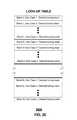
- the selection of the group of tuning stepsis based on a look-up table (e.g., table 1900 of FIG. 19 ) that provides tuning information based on modulation type.
- the tuning information of table 1900can include tuning limits and/or tuning steps that are indexed based on radio access technology and modulation type.
- table 1900can indicate that the group of tuning steps for a 16QAM modulation type is to be limited by 12 degrees and 0.25 dB while the group of tuning steps for a 64QAM modulation type is to be limited by 5 degrees and 0.25 dB in order to avoid an undesired level of symbol error.
- the tablecan indicate that the group of tuning steps for a 16QAM modulation type is to be limited by 10 degrees and 0.25 dB while the group of tuning steps for a 64QAM modulation type is to be limited by 6 degrees and 0.25 dB in order to avoid an undesired level of error vector magnitude.
- multiple tablescan be stored that are based on different undesired conditions (such as symbol error, error vector magnitude, bit error rate, adjacent channel leakage ratio, and so forth) and that are indexed based on modulation type.
- a single tablecan be stored that provides for the most constrained limitation from amongst the undesired conditions so that the group of tuning steps can avoid all of the undesired conditions.
- the tuning limits from table 1900can be used in an algorithm that determines the group of tuning steps to be utilized in order to achieve the desired tuning value within a given time period (such as within a single slot).
- the algorithmcan generate equal tuning steps that achieve these goals or can generate unequal steps (including distinguishing between the size of the steps based on various factors including gradually increasing the step size, taking larger steps initially, and so forth)
- table 1900includes empirical data for the operational criteria (e.g., the maximum allowable phase and amplitude shifts) which can be obtained through testing under various conditions, including using different modulation schemes and/or under various use cases.
- the empirical datacan be pre-determined information that is collected during the development of the communication device for provisioning to the communication device.
- table 1900can be updated based on modifications to modulation schemes, changes to operational requirements (e.g., a service provider's standards change), new modulation schemes, and so forth, where additional testing can be performed based on the new operational circumstances and the new operational criteria (such as changes to the maximum allowable phase and amplitude shifts) can be provisioned to the mobile communication device for use during impedance tuning.
- the communication device 100can include a Digital-to-Analog Converter (DAC), such as a High-Voltage DAC (HVDAC) 160 , coupled with the matching network 120 and the controller 180 so that the HVDAC can receive control signals from the controller and can provide bias signals to the matching network for adjusting the variable reactance element(s) to correspond to the group of tuning steps.
- DACDigital-to-Analog Converter
- HVDACHigh-Voltage DAC
- the exemplary embodimentscan also utilize other components, with or without the HVDAC 160 , for generating and providing control signals that cause the matching network 120 to adjust the variable reactance of the variable reactance element(s).
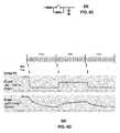
- a timing diagram 200is illustrated that depicts an example of impedance tuning performed by the communication device 100 .
- the HVDAC 160can receive a control signal that includes a rate of tuning adjustment from the controller 180 , which enables the HVDAC to generate bias voltages corresponding to the group of tuning steps based on the received rate of tuning adjustment.
- the controller 180can perform a single write command (that includes the rate of tuning adjustment) to the HVDAC 160 (such as per frame although other timing techniques can also be utilized) that enables multiple different bias voltages to be generated by the HVDAC and applied to the matching network 120 .
- the single write commandcan implement the desired tuning (utilizing multiple smaller tuning steps) without the need for multiple write commands.
- the controller 180implements the impedance tuning based on the rate of tuning adjustment responsive to detecting or otherwise determining an absence of a frequency change in the communications.
- the rate of tuning adjustment in this exemplary embodimentcan enable the HVDAC 160 to be incremented or decremented at a constant rate (e.g., one LSB each cycle—although other increments or decrements can be used) responsive to the received write command until the desired tuning step or value is achieved.
- a constant ratee.g., one LSB each cycle—although other increments or decrements can be used
- the particular number of tuning steps of the group of tuning steps that are utilizedcan vary and can be based on numerous factors, including one or more of the operational criteria (e.g., maximum allowed phase and/or amplitude shifts) that limits the tuning steps, the type of modulation being performed by the communication device 100 , the amount of the overall desired tuning step, and so forth.
- measurement informationsuch as operational parameter(s) from the detector 135
- the controller 180can write the rate of tuning adjustment command to the HVDAC 160 in the second slot of the frame that causes the HVDAC to commence generating bias voltages that adjust the variable reactance of the matching network 120 .
- a gradual tuningcan be performed (as depicted by the descending or ascending sloped line 250 ) based on the HVDAC write commands which eventually provides the desired tuning step or value.
- tuningis performed for each frame, however, the exemplary embodiments can utilize other timing configurations for the write commands and the tuning, including the rate of tuning adjustment causing the gradual tuning over multiple frames and/or the rate of tuning adjustment causing the gradual tuning over less than an entire frame.
- each slot of the framecan be provided with multiple tuning steps which facilitates the gradual tuning over the frame (or a portion thereof) to the desired tuning value.
- the outputis essentially digitally ramped by incrementing or decrementing the DAC.
- the digital rampcan be smoothed by applying an RC filter.
- Some tunable capacitorsemploy resistive bias circuits, so when the DAC drives the tunable capacitor it already sees an RC load that will smooth the ramp. Smoothing the digital ramp is advantageous because the output will more closely approximate a linear response over a given time slot. If the transition is smoothed and has a nearly linear phase response versus time, then the receiver will see the impairment as frequency error. The frequency error can be compensated for by the receiver, whereas abrupt discontinuities in the phase cannot be compensated for and must be limited.
- the exemplary embodimentscan obtain the operational parameter(s) or other information for determining the desired tuning step and/or perform the write commands at various slots of the frames.
- the rate of tuning adjustmentcan be determined so as to satisfy the operational criteria (e.g., the maximum allowed phase and/or amplitude shifts) and to extend the tuning over the entire frame or nearly the entire frame so as to provide a smoother and more gradual transition between tuning values as opposed to a single step tuning technique which may cause a larger phase and/or amplitude shift during a frame slot than desired.
- the controller 180can perform multiple write commands to the HVDAC 160 that indicate each step of the group of tuning steps that are to be utilized so that the HVDAC generates a bias voltage responsive to each write command which adjusts the matching network 120 accordingly.
- one or more of the steps of the group of tuning stepscan be of different step sizes, but still subject to the operational criteria (e.g., limited as to maximum phase and/or amplitude shift).
- each of the group of tuning stepscan be of the same step size.
- the controller 180provides control signals to the HVDAC 160 causing the matching network 160 to be tuned to a desired tuning value by utilizing smaller tuning steps where some of those steps sizes are not equal as shown in the enlarged view 3 A.
- the example of FIG. 3illustrates tuning that can be achieved based on multiple write commands in a single frame where the desired tuning value is obtained during the frame, such as in the first frame approximately half-way through the frame.
- Timing diagram 300also illustrates that the group of tuning steps utilized for achieving the desired tuning value in the second frame can be tuning steps having an equal step size.
- the desired tuning valueis achieved earlier in the frame (after four write commands).
- the particular timing of achieving the desired tuning valuecan vary depending on a number of factors, such as the amount of tuning to be performed, the operational criteria, and so forth.
- the controller 180can perform a single write command to the HVDAC 160 per frame so that the HVDAC generates a bias voltage responsive to each write command which adjusts the matching network 120 accordingly over multiple frames.
- the step sizes over each of the framescan be equal and/or can be of different step sizes, but still subject to the operational criteria (e.g., limited as to maximum phase and/or amplitude shift).
- the example of FIG. 4illustrates tuning that can be achieved based on multiple write commands over multiple frames where the desired tuning value is obtained over multiple frames.
- the particular timing of achieving the desired tuning valuesuch as the number of frames over which the tuning is performed, can vary depending on a number of factors, including the amount of tuning to be performed, the operational criteria, the modulation type, and so forth.
- TDMATime-Division Multiplex Access
- GSMGlobal System for Mobile communications
- one exemplary embodiment of the present disclosurecan avoid, or otherwise compensate for, the degradation based on the receiver and transmitter being switched on and off, and there being times at which neither are active.
- This exemplary embodimentcan utilize the inactive time period for changing the antenna's matching network without impacting, or otherwise reducing the impact on, the transmitted or received signal during the transition.
- CDMACode-Division Multiplex Access
- UMTSCode-Division Multiplex Access
- the tuning states in FIG. 4can be changed while the communication device 100 is transmitting and/or receiving such as, for example, in a WCDMA technology.
- each radio framecan have a small duration (e.g., 10 ms), which can cause the exemplary method to evaluate for any necessary tuning and change the tuning state incrementally, such as once per frame.
- the amount the tuning network is changed for each framecan be determined by the amount of distortion of the RF signal caused by the reactance change and how much distortion can be tolerated by the communication device 100 , including based on the allowable phase and amplitude shifts.
- a sufficiently small change per framecan result in a negligible amount of distortion in the signal, such as, for example, but not limited to, less than or equal to 8 DAC steps per change.
- a small delay in changing the tuning state during the framecan result from the measurement and tuning analysis occurring at the beginning of the frame.
- the exemplary embodimentscan include frames in which there is no change in tuning state and thus no change in the capacitance or other reactance value. For instance, there can be one or more frames in which the capacitance or other reactance value has been adjusted, which are adjacent to one or more frames in which the capacitance or other reactance value has not changed.
- the group of smaller tuning stepscan be generated to achieve the desired tuning step or value through use of an analog ramp output voltage which can adjust the transition of the tuning.
- an analog rampis the output can be smooth and approximately linear.
- Various techniques and componentscan be utilized to implement the analog ramp output voltage to control the transition of tuning.
- Circuit 500can either source or sink a constant current to charge or discharge a capacitor. A constant current into a capacitor can create a ramp voltage of constant dV/dt slope.
- the constant current source 510can utilize a current mirror circuit such that the current sourced from the open pin is equal in magnitude to the current through the resistor. The current is set by (Vsupply ⁇ Vbe)/R.
- the constant current sink 520can use a current mirror circuit such that the current sunk into the open pin is equal in magnitude to the current through the resistor. The current is set by (Vsupply ⁇ Vbe)/R.
- a variable RC filter 650can be used for providing or otherwise approximating a linear or near-linear response as shown in timing diagrams 600 .
- the variable RC filter 650can provide a smaller RC value when the frequency changes (e.g., only when the frequency changes).
- the RC filter 650can provide a larger RC value to minimize transitions.
- the variable RC filter 650can be adjusted for fast transitions when tuning between active periods of discontinuous transmission, such as TDD or frequency changes in FDD.
- the variable RC filter 650can be adjusted for slow transitions during continuous transmission, such as closed loop tuning in FDD.
- variable RC filter 650is one example of a variable RC filter that can be utilized, and other configurations and components can also be utilized in addition to or in place of filter 650 .
- an adjustable R-C time constantcan be utilized to determine an adjustment of a transition between steps of the group of tuning steps to achieve the desired tuning step or value.
- the use of the adjustable R-C time constantenables slowing down of the transition (e.g., on an analog basis) while allowing a faster transition if the circumstances permit.
- the adjustable R-C time constantcan achieve the desired tuning step within a single frame and/or can achieve the desired tuning step over multiple frames.
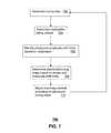
- FIG. 7depicts an illustrative method 700 that may be operated in portions of the communication device 100 .
- the method 700is intended to be an example of how a desired tuning step can be partitioned or otherwise divided into multiple tuning steps so that the transition between tuning values does not result in undesired conditions or so that the undesired conditions are reduced during tuning.
- Method 700can be practiced with more or less of the steps described herein, and can be practiced by devices and components other than those described with respect to the exemplary embodiments.
- a desired tuning step or valuecan be identified or otherwise determined, such as by the controller 180 .
- an open loop processcan be applied in which a use case of the communication device 100 is determined or detected and that use case is mapped to a desired tuning step or value, such as in a look-up table stored in the communication device.
- the desired tuning step or valuecan be determined based on a closed-loop process, such as obtaining operational parameters as feedback and analyzing those operational parameters to determine the desired tuning step or value.
- the particular operational parameters utilized in the closed-loop processcan vary and can include forward and return power (e.g., measured via a detector including a directional coupler), as well as other metrics that are measured and/or determined.
- the controller 180can determine or otherwise identify a modulation type or scheme that is being implemented by the communication device 100 , such as QPSK, 16QAM, 64QAM, and so forth.
- the controllercan identify operational criteria that are to be applied in selecting a group of tuning steps, where the operational criteria are identified based on the type of modulation being implemented.
- the operational criteriacan include a maximum allowable phase shift and/or a maximum allowable amplitude shift for each tuning step of the group of tuning steps.
- the identification of the operational criteriacan be based on a look-up table that has empirical data for the operational criteria mapped to the modulation types.
- the empirical datacan be collected during development of the communication device 100 based on testing where phase and amplitude limits are identified which correspond to undesired conditions, such as bit or symbol errors, and so forth.
- the empirical datacan indicate the maximum allowable phase and/or amplitude shift that should be used for a given time period (such as a slot of a radio frame) in order to avoid an unacceptable level of the undesired condition.
- the operational criteriasuch as the maximum allowable phase and/or amplitude shifts
- the controller 180can generate a control signal that includes a rate of tuning adjustment which provides for bias voltages that will not exceed the phase and/or amplitude shift limits.
- the rate of tuning adjustmentcan be forwarded to the HVDAC 160 as a write command which enables the HVDAC to generate a series of bias voltages which are incremented or decremented based on the rate of tuning adjustment, where the series of bias voltages all satisfy the phase and/or amplitude shift limits.
- the controller 180can also utilize other techniques, based on the operational criteria, to determine or otherwise select the group of tuning steps that will satisfy the operational criteria while also achieving the desired tuning step. For example, the controller 180 can perform multiple write commands to the HVDAC 160 during a single frame resulting in unequal tuning steps being applied by the matching network 120 .
- the matching network 710can be adjusted based on the group of tuning steps, in which each step satisfies the operational criteria, as opposed to a single tuning step that may not satisfy the operational criteria.
- Method 700can be repeated over the duration of the communication session, particularly to account for changes in the user environment or use case which changes the impedance load for the communication device 100 .
- the group of tuning stepscan include a series of tuning steps, such as a larger step broken up into a series of steps that satisfy desired parameters, such as phase and/or magnitude shift limits.
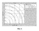
- FIGS. 8-11illustrate errors that may be generated based on tuning too rapidly due to large amplitude and phase shifts.
- FIG. 8illustrates symbol errors for a 16QAM modulation as a function of amplitude error and phase error, where the worst case symbols are on the perimeter of the graph.
- FIG. 9illustrates symbol errors for a 64QAM modulation as a function of amplitude error and phase error, where the worst case symbols are on the perimeter of the graph.
- FIG. 10illustrates symbol error threshold for the 16QAM and 64QAM modulation.
- FIG. 11illustrates Error Vector Magnitude (EVM) thresholds as a function of amplitude error and phase error with respect to a downlink specification.
- EVMError Vector Magnitude
- the EVM thresholdsare for QPSK, 16QAM and 64QAM modulations and indicate specific values of phase and amplitude shift limits that should be applied during tuning to avoid EVM problems and maintain compliance with the EVM specification for downlink. It should be understood that FIGS. 8-11 are exemplary based on modulation types, specific criteria and requirements, and can vary depending on a number of factors, including variations in a service provider's requirements and/or the link budget of the radio.
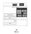
- FIG. 12illustrates processes that can be executed by the communication device 100 in order to obtain a desired tuning step and apply the desired tuning step in a series of smaller tuning steps that satisfy certain operational criteria, such as maximum allowable phase shift and/or maximum allowable amplitude shift.
- the AT Commandis a test interface for setting HVDACs and characterization of the tuner and sense function.
- the Use Case Detectionis a process for detecting or otherwise determining use cases to assist the tuning algorithm when it runs in an open loop mode.
- the Tuning Algorithmdetermines the desired tuning step or value such as in an open-loop and/or closed-loop process, and can be source code provisioned to the communication device 100 .
- the Sense Driverfacilitates obtaining operational parameters that are obtained, such as by the detector 135 , and which are used in a closed-loop process for determining the desired tuning step or value.
- the Live Tuning Datais utilized as a link between the HVDAC and the tuning algorithm.
- the HVDAC Driverfacilitates generating bias voltages to be applied according to the group of tuning steps.
- the Parameter Tablescan include various information, such as an open-loop tuning table and/or an operational criteria table.
- FIG. 13depicts an illustrative embodiment of a communication device 1300 .
- Communication device 1300can include one or more antennas 1301 coupled with a controller 1306 that can determine a desired tuning step or value and which can generate a group of tuning steps to achieve the desired tuning value.
- the group of tuning stepscan be determined or otherwise selected so as to satisfy operational criteria to reduce or eliminate undesired conditions during tuning.
- the operational criteriacan include, among other requirements, a maximum allowable phase shift and/or a maximum allowable amplitude shift.
- the communication device 1300can comprise one or more transceivers 1302 coupled to the antenna 1301 (each transceiver having transmitter and receiver sections (herein transceiver 1302 )), a tunable circuit or matching network 1322 , one or more tuning sensors 1324 , a user interface (UI) 1304 , a power supply 1314 , a location receiver 1316 , a motion sensor 1318 , an orientation sensor 1320 , and the controller 1306 for managing operations thereof.
- the tuning sensor(s) 1324can be used for detecting the operational parameters associated with the antenna 1301 and/or detecting other operational parameters that can be used in a tuning algorithm.
- the transceiver 1302can support short-range or long-range wireless access technologies such as Bluetooth, ZigBee, WiFi, DECT, or cellular communication technologies, just to mention a few.
- Cellular technologiescan include, for example, CDMA-1 ⁇ , UMTS/HSDPA, GSM/GPRS, TDMA/EDGE, EV/DO, WiMAX, SDR, LTE, as well as other next generation wireless communication technologies as they arise.
- the transceiver 1302can also be adapted to support circuit-switched wireline access technologies (such as PSTN), packet-switched wireline access technologies (such as TCP/IP, VoIP, etc.), and combinations thereof.
- the tunable circuit 1322can comprise variable reactive elements such as variable capacitors, variable inductors, or combinations thereof that are tunable with digital and/or analog bias signals based in part on the selected group of tuning steps that satisfy the operational criteria and that achieve the desired tuning value in a desired amount of time (e.g., within a single frame).
- variable reactive elementssuch as variable capacitors, variable inductors, or combinations thereof that are tunable with digital and/or analog bias signals based in part on the selected group of tuning steps that satisfy the operational criteria and that achieve the desired tuning value in a desired amount of time (e.g., within a single frame).
- the tunable circuit 1322can represent a tunable matching network coupled to the antenna(s) 1301 to compensate for a change in impedance of the antenna(s) 1301 , a compensation circuit to compensate for mutual coupling in a multi-antenna system, an amplifier tuning circuit to control operations of an amplifier of the transceiver 1302 , a filter tuning circuit to alter a pass band of a filter of the transceiver 1302 , and so on.
- the tuning sensors 1324can be placed at any stage of the transceiver 1302 such as before or after a matching network 1402 shown in FIG. 14 .
- the tuning sensors or detectors 1324can utilize any suitable sensing technology or components including directional couplers, voltage dividers, or other sensing technologies to measure signals at any stage of the transceiver 1302 .
- the measured signalscan be provided to the controller 1306 by way of analog-to-digital converters included in the tuning sensors 1324 for processing and tuning a variable reactance of the tunable circuit 1322 .
- the UI 1304can include a depressible or touch-sensitive keypad 1308 with a navigation mechanism such as a roller ball, a joystick, a mouse, or a navigation disk for manipulating operations of the communication device 1300 .
- the keypad 1308can be an integral part of a housing assembly of the communication device 1300 or an independent device operably coupled thereto by a tethered wireline interface (such as a USB cable) or a wireless interface supporting, for example, Bluetooth.
- the keypad 1308can represent a numeric keypad commonly used by phones, and/or a QWERTY keypad with alphanumeric keys.
- the UI 1304can further include a display 1310 such as monochrome or color LCD (Liquid Crystal Display), OLED (Organic Light Emitting Diode) or other suitable display technology for conveying images to an end user of the communication device 1300 .
- a display 1310such as monochrome or color LCD (Liquid Crystal Display), OLED (Organic Light Emitting Diode) or other suitable display technology for conveying images to an end user of the communication device 1300 .
- a portion or all of the keypad 1308can be presented by way of the display 1310 with navigation features.
- the display 1310can use touch screen technology to also serve as a user interface for detecting user input.
- the communication device 1300can be adapted to present a user interface with graphical user interface (GUI) elements that can be selected by a user with a touch of a finger.
- GUIgraphical user interface
- the touch screen display 1310can be equipped with capacitive, resistive or other forms of sensing technology to detect how much surface area of a user's finger has been placed on a portion of the touch screen display. This sensing information can be used to control the manipulation of the GUI elements or other functions of the user interface.
- the display 1310can be an integral part of the housing assembly of the communication device 1300 or an independent device communicatively coupled thereto by a tethered wireline interface (such as a cable) or a wireless interface.
- the GUIcan enable a user to input information that facilitates determining the desired tuning value, such as providing a present use case.
- the UI 1304can also include an audio system 1312 that utilizes audio technology for conveying low volume audio (such as audio heard in proximity of a human ear) and high volume audio (such as speakerphone for hands free operation).
- the audio system 1312can further include a microphone for receiving audible signals of an end user.
- the audio system 1312can also be used for voice recognition applications.
- the UI 1304can further include an image sensor 1313 such as a charged coupled device (CCD) camera for capturing still or moving images.
- CCDcharged coupled device
- the power supply 1314can utilize common power management technologies such as replaceable and rechargeable batteries, supply regulation technologies, and/or charging system technologies for supplying energy to the components of the communication device 1300 to facilitate long-range or short-range portable applications.
- the charging systemcan utilize external power sources such as DC power supplied over a physical interface such as a USB port or other suitable tethering technologies.
- the location receiver 1316can utilize location technology such as a global positioning system (GPS) receiver capable of assisted GPS for identifying a location of the communication device 1300 based on signals generated by a constellation of GPS satellites, which can be used for facilitating location services such as navigation.
- GPSglobal positioning system
- the motion sensor 1318can utilize motion sensing technology such as an accelerometer, a gyroscope, or other suitable motion sensing technology to detect motion of the communication device 1300 in three-dimensional space.
- the orientation sensor 1320can utilize orientation sensing technology such as a magnetometer to detect the orientation of the communication device 1300 (north, south, west, and east, as well as combined orientations in degrees, minutes, or other suitable orientation metrics).
- the communication device 1300can use the transceiver 1302 to also determine a proximity to or distance to cellular, WiFi, Bluetooth, or other wireless access points by sensing techniques such as utilizing a received signal strength indicator (RSSI) and/or signal time of arrival (TOA) or time of flight (TOF) measurements.
- the controller 1306can utilize computing technologies such as a microprocessor, a digital signal processor (DSP), and/or a video processor with associated storage memory such as Flash, ROM, RAM, SRAM, DRAM, or other storage technologies for executing computer instructions, controlling, and processing data supplied by the aforementioned components of the communication device 1300 .
- computing technologiessuch as a microprocessor, a digital signal processor (DSP), and/or a video processor with associated storage memory such as Flash, ROM, RAM, SRAM, DRAM, or other storage technologies for executing computer instructions, controlling, and processing data supplied by the aforementioned components of the communication device 1300 .
- the communication device 1300can include a slot for inserting or removing an identity module such as a Subscriber Identity Module (SIM) card. SIM cards can be used for identifying and registering for subscriber services, executing computer programs, storing subscriber data, and so forth.
- SIM cardscan be used for identifying and registering for subscriber services, executing computer programs, storing subscriber data, and so forth.
- the communication device 1300 as described hereincan operate with more or less of the circuit components shown in FIG. 13 . It is further noted that communication device 1300 be an integral part of consumer or industrial devices such as cellular phones, computers, laptops, tablets, utility meters, telemetry measurement devices, and so on.
- the controller 1306can perform antenna tuning for the antenna 1301 (via adjusting the matching networks 1322 ) based on a use case.
- the use casecan be utilized in an open-loop tuning algorithm (e.g., selecting tuning values for one or more variable reactances based on a look up table or other stored values mapped to the use case) and/or can be utilized in conjunction with a closed-loop algorithm (e.g., the use case can be a parameter of the algorithm that also relies upon operational parameters of the communication device, such as output power of the transmitter, return loss, received power, current drain and/or transmitter linearity).
- the pre-defined tuning stateswhich are mapped to the use cases, can be determined during product development or manufacture based on empirical data and can be used as the desired tuning value.
- empirical datacan be stored in a look-up table that is based on a desired TRP and/or TIS, and which can be indexed based on use cases.
- the empirical datacan be obtained through testing under various conditions, including under various use cases.
- the empirical datacan be indexed (e.g., in combination with the use cases) based on other factors including operating frequency, device mode of operation, device operating metrics, and so forth.
- the empirical data of the look-up tablecan be based on desired Uplink (UL) and/or Downlink (DL) throughput, which can be indexed based on use cases. This process enables the communication device 1300 to determine a desired tuning step or value and then to break the desired tuning step or value into a group of tuning steps to avoid undesired conditions that can occur when impedance tuning is performed to rapidly.
- ULUplink
- DLDownlink
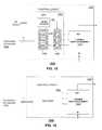
- FIG. 14depicts an illustrative embodiment of a portion of the wireless transceiver 1302 of the communication device 1300 of FIG. 13 .
- the transmit and receive portions of the transceiver 1302can include amplifiers 1401 , 1403 coupled to a tunable matching network 1402 and an impedance load 1406 by way of a switch 1404 .
- the load 1406 in the present illustrationcan include the antenna as shown in FIG. 13 (herein antenna 1406 ).
- a transmit signal in the form of a radio frequency (RF) signal (TX)can be directed to the amplifier 1401 which amplifies the signal and directs the amplified signal to the antenna 1406 by way of the tunable matching network 1402 when switch 1404 is enabled for a transmission session.
- the receive portion of the transceiver 1302can utilize a pre-amplifier 1403 which amplifies signals received from the antenna 1406 by way of the tunable matching network 1402 when switch 1404 is enabled for a receive session.
- FIG. 13are possible for other types of cellular access technologies, such as CDMA. These undisclosed configurations are contemplated by the present disclosure.
- FIGS. 15-16depict illustrative embodiments of the tunable matching network 1402 of the transceiver 1302 of FIG. 14 .
- the tunable matching network 1402can comprise a control circuit 1502 and a tunable reactive element 1510 .
- the control circuit 1502can comprise a DC-to-DC converter 1504 , one or more digital to analog converters (DACs) 1506 and one or more corresponding buffers 1508 to amplify the voltage generated by each DAC.
- the amplified signalcan be fed to one or more tunable reactive components 1704 , 1706 and 1708 such as shown in FIG. 17 , which depicts a possible circuit configuration for the tunable reactive element 1510 .
- the tunable reactive element 1510includes three tunable capacitors 1704 , 1706 , 1708 and an inductor 1702 with a fixed inductance.
- Other circuit configurationsare possible, including use of other components, and are thereby contemplated by the present disclosure.
- the tunable capacitors 1704 , 1706 , 1708can each utilize technology that enables tunability of the capacitance of said component.
- One embodiment of the tunable capacitors 1704 , 1706 , 1708can utilize voltage or current tunable dielectric materials such as a composition of barium strontium titanate (BST).
- BSTbarium strontium titanate
- An illustration of a BST compositionis the Parascan® Tunable Capacitor.
- the tunable reactive element 1510can utilize semiconductor varactors.
- Other present or next generation methods or material compositions that can support a means for a voltage or current tunable reactive elementare contemplated by the present disclosure.
- the DC-to-DC converter 1504can receive a power signal such as 3 Volts from the power supply 1314 of the communication device 1300 in FIG. 13 .
- the DC-to-DC converter 1504can use common technology to amplify this power signal to a higher range (e.g., 30 Volts) such as shown.
- the controller 1306can supply digital signals to each of the DACs 1506 by way of a control bus of “n” or more wires to individually control the capacitance of tunable capacitors 1704 , 1706 , 1708 , thereby varying the collective reactance of the tunable matching network 1402 .
- the control buscan be implemented with a two-wire common serial communications technology such as a Serial Peripheral Interface (SPI) bus.
- SPISerial Peripheral Interface
- the controller 1306can submit serialized digital signals to configure each DAC in FIG. 15 or the switches of the tunable reactive element 1604 of FIG. 16 .
- the control circuit 1502 of FIG. 15can utilize common digital logic to implement the SPI bus and to direct digital signals supplied by the controller 1306 to the DACs.
- the tunable matching network 1402can comprise a control circuit 1602 in the form of a decoder and a tunable reactive element 1604 comprising switchable reactive elements such as shown in FIG. 18 .
- the controller 1306can supply the control circuit 1602 signals via the SPI bus which can be decoded with Boolean or state machine logic to individually enable or disable the switching elements 1802 .
- the switching elements 1802can be implemented using various types of switches, such as semiconductor switches or micro-machined switches including those utilized in micro-electromechanical systems (MEMS).
- MEMSmicro-electromechanical systems
- the tunability of the tunable matching network 1402provides the controller 1306 a means to optimize performance parameters of the transceiver 1202 such as, for example, but not limited to, transmitter power, transmitter efficiency, receiver sensitivity, power consumption of the communication device, a specific absorption rate (SAR) of energy by a human body, frequency band performance parameters, and so forth.
- performance parameters of the transceiver 1202such as, for example, but not limited to, transmitter power, transmitter efficiency, receiver sensitivity, power consumption of the communication device, a specific absorption rate (SAR) of energy by a human body, frequency band performance parameters, and so forth.
- SARspecific absorption rate
- the communication device 1300can utilize a tuning state selection method, such as depicted in FIGS. 2-4 and 7 .
- the radio frequency and/or other RF informationcan be determined, and one or more usage conditions or factors such as, for example, but not limited to, audio path configuration, user interface mode of operation, and radio bearer type, can be used to determine a number of tuning state candidates, which have the highest probability of matching the actual environment of the communication device.
- usage conditions or factorssuch as, for example, but not limited to, audio path configuration, user interface mode of operation, and radio bearer type.
- the look-up table that includes the group of smaller tuning steps based on modulation typescan be static and/or dynamic.
- the look-up tablecan be pre-loaded into the memory of the communication device based on known or estimated factors including modulation type, use cases, usage conditions or factors, and so forth.
- the look-up tablecan be populated or adjusted based on values determined during operation of the communication device, such as from a remote source transmitting the data, including a base station.
- the desired tuning valuecan be determined based on RSSI, Received Signal Code Power (RSCP), Received Signal Quality (RXQUAL), Received Bit Error Rate, current drain, transmit power control level, and so forth as parameters to select a desired tuning value via a look-up table.
- RSCPReceived Signal Code Power
- RXQUALReceived Signal Quality
- Received Bit Error Ratecurrent drain
- transmit power control leveltransmit power control level
- feedback from a cellular base stationcan be utilized in the tuning process. For instance, if the handset is directed to transmit at a lower power step with one tuning state than another, that information could be utilized to determine which tuning state provides a better match for the handset transmitter.
- the algorithmcan set the tuning state and sample the parameter(s) resulting from that tuning state change. In one embodiment, at least one sample for each tuning state setting can be utilized.
- More samplesmay also be utilized in which case the sample order can be interleaved where n different possible tuning states can be set and RSSI or other parameter(s) measured for each, with each of the n states repeated m times. The resultant m measurements for each state can be then be averaged or otherwise processed in order to determine which tuning state will be chosen as the preferred state.
- the desired tuning step or valuecan be identified or otherwise determined based on various goals, such as one or more of a better pre-determined antenna match (e.g., 50 ⁇ ) for each radio Tx/Rx band, achieving better TRP/TIS in the various use cases (e.g., free space, handheld, and other limited modes of operation), a better or best Quality of Service (QoS) with a lower or lowest power consumption.
- a better pre-determined antenna matche.g., 50 ⁇
- TRP/TISin the various use cases
- QoSQuality of Service
- radiated UL throughputcan be compared with a desired UL throughput (e.g., a throughput threshold), such as through use of RSSI measurement, to determine whether tuning is to be performed to improve or maintain the radiated UL throughput.
- a desired UL throughpute.g., a throughput threshold
- One or more of the exemplary embodimentscan take into account that an optimized TRP and/or TIS may not provide the best user experience and can determine the desired tuning step or value accordingly.
- the best user experiencecan be defined by quality of service parameters, such as voice quality and/or data throughput.
- QoSmay not be directly proportional or otherwise 100% related to TRP and TIS, which are just two variables of QoS function.
- the desired tuning step or valuecan be obtained from one or more look-up tables 2000 as depicted in FIG. 20 .
- the look-up table 2000can be indexed (e.g., by the controller 1306 of the communication device 1300 of FIG. 13 ) during operation according to band and/or use case.
- the look-up table 2000can be static and/or dynamic.
- the look-up table 2000can be pre-loaded into the memory of the communication device 1300 based on known or estimated use cases, usage conditions or factors, and so forth.
- the look-up table 2000can be populated or adjusted based on values determined during operation of the communication device 1300 .
- the desired tuning stepcan be based on a subset of use cases that are selected from a group of use cases stored in a memory of the communication device, such as in table 2000 .
- a methodin which a controller can determine an adjustment to be made to an impedance matching network of a communication device that is utilizing Code Division Multiple Access (CDMA) communication, and in which the controller can adjust the impedance matching network while the communication device is performing at least one of receiving or transmitting signals, where at least two adjacent frames of the CDMA communication have different variable reactance values for the impedance matching network.
- the methodcan include the controller determining a reactance change per frame of the CDMA communication based on an amount of distortion of an RF signal caused by the reactance change.
- a physical use case that is utilized in determining the desired tuning step or valuecan represent a physical state of the communication device, while a functional use case can represent an operational state of the communication device.
- a flip phone 2100 of FIG. 21 aan open flip can represent one physical use case, while a closed flip can represent another physical use case.
- a closed flip statei.e., bottom and top flips 2102 - 2104 are aligned
- a usermay have his/her hands surrounding the top flip 2102 and the bottom flip 2104 while holding the phone 2100 , which can result in one range of load impedances experienced by an internal or retrievable antenna (not shown) of the phone 2100 .
- the range of load impedances of the internal or retrievable antennacan be determined by empirical analysis. With the flip open a user may hold the bottom flip 2102 with one hand while positioning the top flip 2104 near the user's ear when an audio system of the phone 2100 is set to low volume. If, on the other hand, the audio system is in speakerphone mode, the user may be positioning the top flip 2104 away from the user's ear. In these arrangements, different ranges of load impedances can be experienced by the internal or retrievable antenna, which can be analyzed empirically.
- the low and high volume states of the audio systemillustrate varying functional use cases. Other examples of use cases can include handheld operations such as shown by FIG. 21B , handheld and phone-to-head operations such as shown in FIG.
- the determined or detected use casecan be either or both of a physical or functional use case.
- the keypad in an outward positioncan present one range of load impedances of an internal antenna, while the keypad in a hidden position can present another range of load impedances, each of which can be analyzed empirically.
- the smartphone 2300illustrated in FIG. 23
- the usermay hold the phone away from the user's ear in order to view the game. Placing the smartphone 2300 in a portrait position 2302 can represent one physical and operational use case, while utilizing the smartphone 2300 in a landscape position 2304 presents another physical and operational use case.
- a multimode phone 2400 capable of facilitating multiple access technologies such as GSM, CDMA, LTE, WiFi, GPS, and/or Bluetooth in two or more combinationscan provide additional insight into possible ranges of impedances experienced by two or more internal antennas of the multimode phone 2400 .
- a multimode phone 2400 that provides GPS services by processing signals received from a constellation of satellites 2402 , 2404can be empirically analyzed when other access technologies are also in use.
- the multimode phone 2400is facilitating voice communications by exchanging wireless messages with a cellular base station 2406 .
- an internal antenna of the GPS receivermay be affected by a use case of a user holding the multimode phone 2400 (e.g., near the user's ear or away from the user's ear).
- the effect on the GPS receiver antenna and the GSM antenna by the user's hand positioncan be empirically analyzed.
- the antenna of a GSM transceiveris in close proximity to the antenna of a WiFi transceiver.
- the GSM frequency band used to facilitate voice communicationsis near the operational frequency of the WiFi transceiver.
- a use case for voice communicationsmay result in certain physical states of the multimode phone 2400 (e.g., slider out), which can result in a particular hand position of the user of the multimode phone 2400 .
- Such a physical and functional use casecan affect the impedance range of the antenna of the WiFi transceiver as well as the antenna of the GSM transceiver.
- a close proximity between the WiFi and GSM antennas and the near operational frequency of the antennasmay also result in cross-coupling between the antennas, thereby changing the load impedance of each of the antennas.
- Cross-coupling under these circumstancescan be measured empirically.
- empirical measurements of the impedances of other internal antennascan be measured for particular physical and functional use configurations when utilizing Bluetooth, WiFi, Zigbee, or other access technologies in peer-to-peer communications with another communication device 2408 or with a wireless access point 2410 .
- the number of physical and functional use cases of the communication device 1300can be substantial when accounting for combinations of access technologies, frequency bands, antennas of multiple access technologies, antennas configured for diversity designs such as multiple-input and multiple output (MIMO) antennas, and so on. These combinations, however, can be empirically analyzed for load impedances and effects on other tunable circuits.
- the empirical data collectedcan be recorded in the look-up table of FIG. 20 and indexed according to corresponding combinations of physical and functional use cases.
- the information stored in the look-up tablecan be used in open-loop RF tuning applications to initialize tunable circuit components of a transceiver, as well as, tuning algorithms that control operational aspects of the tunable circuit components.
- FIG. 25depicts an exemplary diagrammatic representation of a machine in the form of a computer system 2500 within which a set of instructions, when executed, may cause the machine to perform any one or more of the methodologies discussed above.
- the machineoperates as a standalone device.
- the machinemay be connected (e.g., using a network) to other machines.
- the machinemay operate in the capacity of a server or a client user machine in server-client user network environment, or as a peer machine in a peer-to-peer (or distributed) network environment.
- the machinemay comprise a server computer, a client user computer, a personal computer (PC), a tablet PC, a laptop computer, a desktop computer, a control system, a network router, switch or bridge, or any machine capable of executing a set of instructions (sequential or otherwise) that specify actions to be taken by that machine.
- a device of the present disclosureincludes broadly any electronic device that provides voice, video or data communication.
- the term “machine”shall also be taken to include any collection of machines that individually or jointly execute a set (or multiple sets) of instructions to perform any one or more of the methodologies discussed herein.
- the computer system 2500may include a processor 2502 (e.g., a central processing unit (CPU), a graphics processing unit (GPU, or both), a main memory 2504 and a static memory 2506 , which communicate with each other via a bus 2508 .
- the computer system 2500may further include a video display unit 2510 (e.g., a liquid crystal display (LCD), a flat panel, a solid state display, or a cathode ray tube (CRT)).
- the computer system 2500may include an input device 2512 (e.g., a keyboard), a cursor control device 2514 (e.g., a mouse), a disk drive unit 2516 , a signal generation device 2518 (e.g., a speaker or remote control) and a network interface device 2520 .
- an input device 2512e.g., a keyboard
- a cursor control device 2514e.g., a mouse
- a disk drive unit 2516e.g., a disk drive unit
- a signal generation device 2518e.g., a speaker or remote control
- the disk drive unit 2516may include a machine-readable medium 2522 on which is stored one or more sets of instructions (e.g., software 2524 ) embodying any one or more of the methodologies or functions described herein, including those methods illustrated above.
- the instructions 2524may also reside, completely or at least partially, within the main memory 2504 , the static memory 2506 , and/or within the processor 2502 during execution thereof by the computer system 2500 .
- the main memory 2504 and the processor 2502also may constitute machine-readable media.
- Dedicated hardware implementationsincluding, but not limited to, application specific integrated circuits, programmable logic arrays and other hardware devices can likewise be constructed to implement the methods described herein.
- Applicationsthat may include the apparatus and systems of various embodiments broadly include a variety of electronic and computer systems. Some embodiments implement functions in two or more specific interconnected hardware modules or devices with related control and data signals communicated between and through the modules, or as portions of an application-specific integrated circuit.
- the example systemis applicable to software, firmware, and hardware implementations.
- the methods described hereinare intended for operation as software programs running on a computer processor.
- software implementationscan include, but not limited to, distributed processing or component/object distributed processing, parallel processing, or virtual machine processing can also be constructed to implement the methods described herein.
- the present disclosurecontemplates a machine readable medium containing instructions 2524 , or that which receives and executes instructions 2524 from a propagated signal so that a device connected to a network environment 2526 can send or receive voice, video or data, and to communicate over the network 2526 using the instructions 2524 .
- the instructions 2524may further be transmitted or received over a network 2526 via the network interface device 2520 .
- machine-readable medium 2522is shown in an example embodiment to be a single medium, the term “machine-readable medium” should be taken to include a single medium or multiple media (e.g., a centralized or distributed database, and/or associated caches and servers) that store the one or more sets of instructions.
- the term “machine-readable medium”shall also be taken to include any medium that is capable of storing, encoding or carrying a set of instructions for execution by the machine and that cause the machine to perform any one or more of the methodologies of the present disclosure.
- machine-readable mediumshall accordingly be taken to include, but not be limited to: solid-state memories such as a memory card or other package that houses one or more read-only (non-volatile) memories, random access memories, or other re-writable (volatile) memories; magneto-optical or optical medium such as a disk or tape; and/or a digital file attachment to e-mail or other self-contained information archive or set of archives is considered a distribution medium equivalent to a tangible storage medium. Accordingly, the disclosure is considered to include any one or more of a machine-readable medium or a distribution medium, as listed herein and including art-recognized equivalents and successor media, in which the software implementations herein are stored.
- inventive subject mattermay be referred to herein, individually and/or collectively, by the term “invention” merely for convenience and without intending to voluntarily limit the scope of this application to any single invention or inventive concept if more than one is in fact disclosed.
- inventive conceptmerely for convenience and without intending to voluntarily limit the scope of this application to any single invention or inventive concept if more than one is in fact disclosed.
Landscapes
- Engineering & Computer Science (AREA)
- Computer Networks & Wireless Communication (AREA)
- Signal Processing (AREA)
- Transmitters (AREA)
Abstract
Description
Claims (20)
Priority Applications (3)
| Application Number | Priority Date | Filing Date | Title |
|---|---|---|---|
| US15/161,966US9768810B2 (en) | 2012-12-21 | 2016-05-23 | Method and apparatus for adjusting the timing of radio antenna tuning |
| US15/609,834US10404295B2 (en) | 2012-12-21 | 2017-05-31 | Method and apparatus for adjusting the timing of radio antenna tuning |
| US16/512,885US10700719B2 (en) | 2012-12-21 | 2019-07-16 | Method and apparatus for adjusting the timing of radio antenna tuning |
Applications Claiming Priority (2)
| Application Number | Priority Date | Filing Date | Title |
|---|---|---|---|
| US13/724,040US9374113B2 (en) | 2012-12-21 | 2012-12-21 | Method and apparatus for adjusting the timing of radio antenna tuning |
| US15/161,966US9768810B2 (en) | 2012-12-21 | 2016-05-23 | Method and apparatus for adjusting the timing of radio antenna tuning |
Related Parent Applications (1)
| Application Number | Title | Priority Date | Filing Date |
|---|---|---|---|
| US13/724,040ContinuationUS9374113B2 (en) | 2012-12-21 | 2012-12-21 | Method and apparatus for adjusting the timing of radio antenna tuning |
Related Child Applications (1)
| Application Number | Title | Priority Date | Filing Date |
|---|---|---|---|
| US15/609,834Continuation-In-PartUS10404295B2 (en) | 2012-12-21 | 2017-05-31 | Method and apparatus for adjusting the timing of radio antenna tuning |
Publications (2)
| Publication Number | Publication Date |
|---|---|
| US20160269055A1 US20160269055A1 (en) | 2016-09-15 |
| US9768810B2true US9768810B2 (en) | 2017-09-19 |
Family
ID=50974626
Family Applications (2)
| Application Number | Title | Priority Date | Filing Date |
|---|---|---|---|
| US13/724,040Active2033-09-12US9374113B2 (en) | 2012-12-21 | 2012-12-21 | Method and apparatus for adjusting the timing of radio antenna tuning |
| US15/161,966ActiveUS9768810B2 (en) | 2012-12-21 | 2016-05-23 | Method and apparatus for adjusting the timing of radio antenna tuning |
Family Applications Before (1)
| Application Number | Title | Priority Date | Filing Date |
|---|---|---|---|
| US13/724,040Active2033-09-12US9374113B2 (en) | 2012-12-21 | 2012-12-21 | Method and apparatus for adjusting the timing of radio antenna tuning |
Country Status (1)
| Country | Link |
|---|---|
| US (2) | US9374113B2 (en) |
Cited By (9)
| Publication number | Priority date | Publication date | Assignee | Title |
|---|---|---|---|---|
| US10050598B2 (en) | 2006-11-08 | 2018-08-14 | Blackberry Limited | Method and apparatus for adaptive impedance matching |
| US10177731B2 (en)* | 2006-01-14 | 2019-01-08 | Blackberry Limited | Adaptive matching network |
| US10218070B2 (en) | 2011-05-16 | 2019-02-26 | Blackberry Limited | Method and apparatus for tuning a communication device |
| US10263595B2 (en) | 2010-03-22 | 2019-04-16 | Blackberry Limited | Method and apparatus for adapting a variable impedance network |
| US10404295B2 (en)* | 2012-12-21 | 2019-09-03 | Blackberry Limited | Method and apparatus for adjusting the timing of radio antenna tuning |
| US10651918B2 (en) | 2014-12-16 | 2020-05-12 | Nxp Usa, Inc. | Method and apparatus for antenna selection |
| US10659088B2 (en) | 2009-10-10 | 2020-05-19 | Nxp Usa, Inc. | Method and apparatus for managing operations of a communication device |
| USRE48435E1 (en) | 2007-11-14 | 2021-02-09 | Nxp Usa, Inc. | Tuning matching circuits for transmitter and receiver bands as a function of the transmitter metrics |
| US10979095B2 (en) | 2011-02-18 | 2021-04-13 | Nxp Usa, Inc. | Method and apparatus for radio antenna frequency tuning |
Families Citing this family (34)
| Publication number | Priority date | Publication date | Assignee | Title |
|---|---|---|---|---|
| US8744384B2 (en) | 2000-07-20 | 2014-06-03 | Blackberry Limited | Tunable microwave devices with auto-adjusting matching circuit |
| US7535312B2 (en) | 2006-11-08 | 2009-05-19 | Paratek Microwave, Inc. | Adaptive impedance matching apparatus, system and method with improved dynamic range |
| US7917104B2 (en) | 2007-04-23 | 2011-03-29 | Paratek Microwave, Inc. | Techniques for improved adaptive impedance matching |
| US8072285B2 (en) | 2008-09-24 | 2011-12-06 | Paratek Microwave, Inc. | Methods for tuning an adaptive impedance matching network with a look-up table |
| JP5901612B2 (en) | 2010-04-20 | 2016-04-13 | ブラックベリー リミテッド | Method and apparatus for managing interference in a communication device |
| EP2740221B1 (en) | 2011-08-05 | 2019-06-26 | BlackBerry Limited | Method and apparatus for band tuning in a communication device |
| US8948889B2 (en) | 2012-06-01 | 2015-02-03 | Blackberry Limited | Methods and apparatus for tuning circuit components of a communication device |
| US9853363B2 (en) | 2012-07-06 | 2017-12-26 | Blackberry Limited | Methods and apparatus to control mutual coupling between antennas |
| US9350405B2 (en) | 2012-07-19 | 2016-05-24 | Blackberry Limited | Method and apparatus for antenna tuning and power consumption management in a communication device |
| US9813262B2 (en) | 2012-12-03 | 2017-11-07 | Google Technology Holdings LLC | Method and apparatus for selectively transmitting data using spatial diversity |
| US9591508B2 (en) | 2012-12-20 | 2017-03-07 | Google Technology Holdings LLC | Methods and apparatus for transmitting data between different peer-to-peer communication groups |
| US9374113B2 (en)* | 2012-12-21 | 2016-06-21 | Blackberry Limited | Method and apparatus for adjusting the timing of radio antenna tuning |
| US9979531B2 (en) | 2013-01-03 | 2018-05-22 | Google Technology Holdings LLC | Method and apparatus for tuning a communication device for multi band operation |
| US10229697B2 (en) | 2013-03-12 | 2019-03-12 | Google Technology Holdings LLC | Apparatus and method for beamforming to obtain voice and noise signals |
| US9960791B2 (en)* | 2013-12-12 | 2018-05-01 | Ethertronics, Inc. | RF integrated circuit with tunable component and memory |
| US9549290B2 (en) | 2013-12-19 | 2017-01-17 | Google Technology Holdings LLC | Method and apparatus for determining direction information for a wireless device |
| US10141655B2 (en) | 2014-02-25 | 2018-11-27 | Ethertronics, Inc. | Switch assembly with integrated tuning capability |
| FR3018637B1 (en)* | 2014-03-13 | 2018-08-17 | Samsung Electronics Co., Ltd. | RADIO COMMUNICATION USING MULTIPLE ANTENNAS AND LOCATION VARIABLES |
| US9491007B2 (en) | 2014-04-28 | 2016-11-08 | Google Technology Holdings LLC | Apparatus and method for antenna matching |
| US9478847B2 (en) | 2014-06-02 | 2016-10-25 | Google Technology Holdings LLC | Antenna system and method of assembly for a wearable electronic device |
| US20160036482A1 (en)* | 2014-07-29 | 2016-02-04 | Google Technology Holdings LLC | Apparatus and method for antenna tuning |
| JPWO2016021105A1 (en)* | 2014-08-07 | 2017-05-18 | パナソニックIpマネジメント株式会社 | Wireless device |
| US20160050569A1 (en)* | 2014-08-18 | 2016-02-18 | Litepoint Corporation | Method for testing implicit beamforming performance of a multiple-input multiple-output radio frequency data packet signal transceiver |
| WO2017033563A1 (en)* | 2015-08-26 | 2017-03-02 | 株式会社村田製作所 | Antenna tuner control circuit, front-end circuit and communication device |
| US10707562B2 (en)* | 2015-09-22 | 2020-07-07 | Futurewei Technologies, Inc. | System and method for adaptive aperture tunable antenna |
| CN105426578B (en)* | 2015-11-03 | 2018-06-19 | 电子科技大学 | A kind of MIMO-SAR planar array element position optimization methods based on genetic algorithm |
| US9929760B2 (en)* | 2016-04-14 | 2018-03-27 | Taiwan Semiconductor Manufacturing Co., Ltd. | Ultra-low-power RF receiver frontend with tunable matching networks |
| US10476534B2 (en)* | 2016-12-06 | 2019-11-12 | Qorvo Us, Inc. | Multi-band radio frequency circuit |
| US11283557B2 (en)* | 2017-04-28 | 2022-03-22 | Panasonic Intellectual Property Corporation Of America | Measurement apparatus and measurement method |
| US10574286B2 (en)* | 2017-09-01 | 2020-02-25 | Qualcomm Incorporated | High selectivity TDD RF front end |
| JP7099348B2 (en)* | 2019-02-08 | 2022-07-12 | 株式会社Jvcケンウッド | Wireless communication device |
| US11211704B2 (en)* | 2019-05-29 | 2021-12-28 | Metawave Corporation | Switched coupled inductance phase shift mechanism |
| WO2022075253A1 (en)* | 2020-10-09 | 2022-04-14 | 株式会社村田製作所 | High frequency circuit and communication device |
| US11309924B1 (en)* | 2020-10-16 | 2022-04-19 | Nxp Usa, Inc. | Methods and apparatuses for mitigating an impact of settling times of components in matching networks |
Citations (468)
| Publication number | Priority date | Publication date | Assignee | Title |
|---|---|---|---|---|
| US2745067A (en) | 1951-06-28 | 1956-05-08 | True Virgil | Automatic impedance matching apparatus |
| US3117279A (en) | 1962-06-04 | 1964-01-07 | Collins Radio Co | Automatically controlled antenna tuning and loading system |
| US3160832A (en) | 1961-12-22 | 1964-12-08 | Collins Radio Co | Automatic coupling and impedance matching network |
| US3390337A (en) | 1966-03-15 | 1968-06-25 | Avco Corp | Band changing and automatic tuning apparatus for transmitter tau-pad output filter |
| US3443231A (en) | 1966-04-27 | 1969-05-06 | Gulf General Atomic Inc | Impedance matching system |
| US3509500A (en) | 1966-12-05 | 1970-04-28 | Avco Corp | Automatic digital tuning apparatus |
| US3571716A (en) | 1968-04-16 | 1971-03-23 | Motorola Inc | Electronically tuned antenna system |
| US3590385A (en) | 1969-07-25 | 1971-06-29 | Avco Corp | Semi-automatic tuning circuit for an antenna coupler |
| US3601717A (en) | 1969-11-20 | 1971-08-24 | Gen Dynamics Corp | System for automatically matching a radio frequency power output circuit to a load |
| US3742279A (en) | 1971-02-10 | 1973-06-26 | Burroughs Corp | Segmented electrode display panel having closed structure |
| US3749491A (en) | 1972-02-07 | 1973-07-31 | Stromberg Datagraphix Inc | Microfiche duplicator |
| US3794941A (en) | 1972-05-08 | 1974-02-26 | Hughes Aircraft Co | Automatic antenna impedance tuner including digital control circuits |
| US3919644A (en) | 1970-02-02 | 1975-11-11 | Gen Dynamics Corp | Automatic antenna coupler utilizing system for measuring the real part of the complex impedance or admittance presented by an antenna or other network |
| US3990024A (en) | 1975-01-06 | 1976-11-02 | Xerox Corporation | Microstrip/stripline impedance transformer |
| US3995237A (en) | 1974-10-15 | 1976-11-30 | Cincinnati Electronics Corporation | Automatic matching method and apparatus |
| US4186359A (en) | 1977-08-22 | 1980-01-29 | Tx Rx Systems Inc. | Notch filter network |
| US4201960A (en) | 1978-05-24 | 1980-05-06 | Motorola, Inc. | Method for automatically matching a radio frequency transmitter to an antenna |
| US4227256A (en) | 1978-01-06 | 1980-10-07 | Quadracast Systems, Inc. | AM Broadcast tuner with automatic gain control |
| US4383441A (en) | 1981-07-20 | 1983-05-17 | Ford Motor Company | Method for generating a table of engine calibration control values |
| US4476578A (en) | 1981-11-27 | 1984-10-09 | Thomson-Csf | Device for detecting the optimum anode load impedance of a tube transmitter in a high frequency transmission chain |
| US4493112A (en) | 1981-11-19 | 1985-01-08 | Rockwell International Corporation | Antenna tuner discriminator |
| US4509019A (en) | 1983-01-27 | 1985-04-02 | At&T Bell Laboratories | Tunable active filter |
| US4777490A (en) | 1986-04-22 | 1988-10-11 | General Electric Company | Monolithic antenna with integral pin diode tuning |
| US4799066A (en) | 1985-07-26 | 1989-01-17 | The Marconi Company Limited | Impedance matching arrangement |
| JPH0277580A (en) | 1988-09-12 | 1990-03-16 | Sekisui Chem Co Ltd | Production of ceramic coated body |
| US4965607A (en) | 1987-04-30 | 1990-10-23 | Br Communications, Inc. | Antenna coupler |
| US4970478A (en) | 1989-06-14 | 1990-11-13 | Honeywell, Inc. | Matched microwave variable attenuator |
| US4980656A (en) | 1989-12-01 | 1990-12-25 | Motorola, Inc. | Active input impedance tuner for compensating for power loss |
| US5032805A (en) | 1989-10-23 | 1991-07-16 | The United States Of America As Represented By The Secretary Of The Army | RF phase shifter |
| JPH03276901A (en) | 1990-03-27 | 1991-12-09 | Mitsubishi Electric Corp | Hybrid integrated circuit device |
| US5136478A (en) | 1990-08-03 | 1992-08-04 | Quadri Electronics Corporation | Solid electrolyte capacitor and method of making |
| US5142255A (en) | 1990-05-07 | 1992-08-25 | The Texas A&M University System | Planar active endfire radiating elements and coplanar waveguide filters with wide electronic tuning bandwidth |
| US5177670A (en) | 1991-02-08 | 1993-01-05 | Hitachi, Ltd. | Capacitor-carrying semiconductor module |
| US5195045A (en) | 1991-02-27 | 1993-03-16 | Astec America, Inc. | Automatic impedance matching apparatus and method |
| US5200826A (en) | 1990-06-21 | 1993-04-06 | Samsung Electronics Co., Ltd. | TV signal receiving double conversion television tuner system having automatic gain control provisions |
| US5212463A (en) | 1992-07-22 | 1993-05-18 | The United States Of America As Represented By The Secretary Of The Army | Planar ferro-electric phase shifter |
| US5216392A (en) | 1991-07-05 | 1993-06-01 | Motorola, Inc. | Automatically controlled varactor tuned matching networks for a crystal filter |
| US5230091A (en) | 1989-09-25 | 1993-07-20 | Nokia Mobile Phones Ltd. | Method and apparatus for tuning and compensating power levels in a radio telephone |
| US5243358A (en) | 1991-07-15 | 1993-09-07 | Ball Corporation | Directional scanning circular phased array antenna |
| US5258728A (en) | 1987-09-30 | 1993-11-02 | Fujitsu Ten Limited | Antenna circuit for a multi-band antenna |
| US5276912A (en) | 1990-02-06 | 1994-01-04 | Motorola, Inc. | Radio frequency power amplifier having variable output power |
| US5301358A (en) | 1988-12-05 | 1994-04-05 | Seiko Corp. | Automatic antenna tuning method and apparatus |
| US5307033A (en) | 1993-01-19 | 1994-04-26 | The United States Of America As Represented By The Secretary Of The Army | Planar digital ferroelectric phase shifter |
| US5310358A (en) | 1992-12-22 | 1994-05-10 | The Whitaker Corporation | Computer docking system |
| US5312790A (en) | 1993-06-09 | 1994-05-17 | The United States Of America As Represented By The Secretary Of The Army | Ceramic ferroelectric material |
| US5334958A (en) | 1993-07-06 | 1994-08-02 | The United States Of America As Represented By The Secretary Of The Army | Microwave ferroelectric phase shifters and methods for fabricating the same |
| US5361403A (en)* | 1990-11-14 | 1994-11-01 | Ericsson Ge Mobile Communication Holding, Inc. | AM-FM transmitter power amplifier |
| US5371473A (en) | 1993-09-10 | 1994-12-06 | Hughes Aircraft Company | Thermally stable ALC for pulsed output amplifier |
| US5409889A (en) | 1993-05-03 | 1995-04-25 | Das; Satyendranath | Ferroelectric high Tc superconductor RF phase shifter |
| US5430417A (en) | 1991-07-05 | 1995-07-04 | Aft Advanced Ferrite Technology Gmbh | Tunable matching network |
| US5446447A (en) | 1994-02-16 | 1995-08-29 | Motorola, Inc. | RF tagging system including RF tags with variable frequency resonant circuits |
| US5448252A (en) | 1994-03-15 | 1995-09-05 | The United States Of America As Represented By The Secretary Of The Air Force | Wide bandwidth microstrip patch antenna |
| US5451567A (en) | 1994-03-30 | 1995-09-19 | Das; Satyendranath | High power ferroelectric RF phase shifter |
| US5451914A (en) | 1994-07-05 | 1995-09-19 | Motorola, Inc. | Multi-layer radio frequency transformer |
| US5457394A (en) | 1993-04-12 | 1995-10-10 | The Regents Of The University Of California | Impulse radar studfinder |
| US5472935A (en) | 1992-12-01 | 1995-12-05 | Yandrofski; Robert M. | Tuneable microwave devices incorporating high temperature superconducting and ferroelectric films |
| EP0685936A2 (en) | 1994-05-25 | 1995-12-06 | Nokia Mobile Phones Ltd. | Adaptive antenna matching |
| US5479139A (en) | 1995-04-19 | 1995-12-26 | The United States Of America As Represented By The Secretary Of The Army | System and method for calibrating a ferroelectric phase shifter |
| US5496795A (en) | 1994-08-16 | 1996-03-05 | Das; Satyendranath | High TC superconducting monolithic ferroelectric junable b and pass filter |
| US5502372A (en) | 1994-10-07 | 1996-03-26 | Hughes Aircraft Company | Microstrip diagnostic probe for thick metal flared notch and ridged waveguide radiators |
| US5524281A (en) | 1988-03-31 | 1996-06-04 | Wiltron Company | Apparatus and method for measuring the phase and magnitude of microwave signals |
| US5548837A (en) | 1994-03-28 | 1996-08-20 | Hess; Garry C. | Method and apparatus for producing diversity gain of a received signal |
| US5561407A (en) | 1995-01-31 | 1996-10-01 | The United States Of America As Represented By The Secretary Of The Army | Single substrate planar digital ferroelectric phase shifter |
| US5564086A (en) | 1993-11-29 | 1996-10-08 | Motorola, Inc. | Method and apparatus for enhancing an operating characteristic of a radio transmitter |
| US5583359A (en) | 1995-03-03 | 1996-12-10 | Northern Telecom Limited | Capacitor structure for an integrated circuit |
| US5589844A (en) | 1995-06-06 | 1996-12-31 | Flash Comm, Inc. | Automatic antenna tuner for low-cost mobile radio |
| US5593495A (en) | 1994-06-16 | 1997-01-14 | Sharp Kabushiki Kaisha | Method for manufacturing thin film of composite metal-oxide dielectric |
| US5635434A (en) | 1995-09-11 | 1997-06-03 | The United States Of America As Represented By The Secretary Of The Army | Ceramic ferroelectric composite material-BSTO-magnesium based compound |
| US5635433A (en) | 1995-09-11 | 1997-06-03 | The United States Of America As Represented By The Secretary Of The Army | Ceramic ferroelectric composite material-BSTO-ZnO |
| US5640042A (en) | 1995-12-14 | 1997-06-17 | The United States Of America As Represented By The Secretary Of The Army | Thin film ferroelectric varactor |
| DE19614655A1 (en) | 1996-04-13 | 1997-10-16 | Daimler Benz Aerospace Ag | Automatic antenna matching device for short wave station |
| US5679624A (en) | 1995-02-24 | 1997-10-21 | Das; Satyendranath | High Tc superconductive KTN ferroelectric time delay device |
| US5689219A (en) | 1994-06-30 | 1997-11-18 | Nokia Telecommunications Oy | Summing network |
| US5694134A (en) | 1992-12-01 | 1997-12-02 | Superconducting Core Technologies, Inc. | Phased array antenna system including a coplanar waveguide feed arrangement |
| US5693429A (en) | 1995-01-20 | 1997-12-02 | The United States Of America As Represented By The Secretary Of The Army | Electronically graded multilayer ferroelectric composites |
| JPH09321526A (en) | 1996-05-27 | 1997-12-12 | Kokusai Electric Co Ltd | Adaptive array antenna |
| US5699071A (en) | 1991-03-26 | 1997-12-16 | Sumitomo Chemical Company, Limited | Glass antenna system for automobile |
| US5766697A (en) | 1995-12-08 | 1998-06-16 | The United States Of America As Represented By The Secretary Of The Army | Method of making ferrolectric thin film composites |
| US5777581A (en) | 1995-12-07 | 1998-07-07 | Atlantic Aerospace Electronics Corporation | Tunable microstrip patch antennas |
| US5786727A (en) | 1996-10-15 | 1998-07-28 | Motorola, Inc. | Multi-stage high efficiency linear power amplifier and method therefor |
| JPH10209722A (en) | 1997-01-20 | 1998-08-07 | Seiko Epson Corp | High frequency circuit and method of manufacturing the same |
| US5812572A (en) | 1996-07-01 | 1998-09-22 | Pacific Fiberoptics, Inc. | Intelligent fiberoptic transmitters and methods of operating and manufacturing the same |
| US5812943A (en) | 1995-09-01 | 1998-09-22 | Nec Corporation | High frequency band high temperature superconductor mixer antenna which allows a superconductor feed line to be used in a low frequency region |
| US5830591A (en) | 1996-04-29 | 1998-11-03 | Sengupta; Louise | Multilayered ferroelectric composite waveguides |
| US5846893A (en) | 1995-12-08 | 1998-12-08 | Sengupta; Somnath | Thin film ferroelectric composites and method of making |
| US5874926A (en) | 1996-03-11 | 1999-02-23 | Murata Mfg Co. Ltd | Matching circuit and antenna apparatus |
| US5880635A (en) | 1997-04-16 | 1999-03-09 | Sony Corporation | Apparatus for optimizing the performance of a power amplifier |
| US5886867A (en) | 1995-03-21 | 1999-03-23 | Northern Telecom Limited | Ferroelectric dielectric for integrated circuit applications at microwave frequencies |
| US5892482A (en) | 1996-12-06 | 1999-04-06 | Raytheon Company | Antenna mutual coupling neutralizer |
| EP0909024A2 (en) | 1997-10-07 | 1999-04-14 | Sharp Kabushiki Kaisha | Impedance matching device |
| US5926751A (en) | 1997-02-19 | 1999-07-20 | Motorola, Inc. | Method and apparatus for receiving communication signals |
| US5929717A (en) | 1998-01-09 | 1999-07-27 | Lam Research Corporation | Method of and apparatus for minimizing plasma instability in an RF processor |
| US5940030A (en) | 1998-03-18 | 1999-08-17 | Lucent Technologies, Inc. | Steerable phased-array antenna having series feed network |
| US5963871A (en) | 1996-10-04 | 1999-10-05 | Telefonaktiebolaget Lm Ericsson | Retractable multi-band antennas |
| US5969582A (en) | 1997-07-03 | 1999-10-19 | Ericsson Inc. | Impedance matching circuit for power amplifier |
| US5973568A (en) | 1998-06-01 | 1999-10-26 | Motorola Inc. | Power amplifier output module for dual-mode digital systems |
| US5982099A (en) | 1996-03-29 | 1999-11-09 | Lam Research Corporation | Method of and apparatus for igniting a plasma in an r.f. plasma processor |
| US5990766A (en) | 1996-06-28 | 1999-11-23 | Superconducting Core Technologies, Inc. | Electrically tunable microwave filters |
| US6008759A (en) | 1997-12-05 | 1999-12-28 | Alcatel | Method of determining the direction of arrival of a radio signal, as well as radio base station and radiocommunications system |
| US6009124A (en) | 1997-09-22 | 1999-12-28 | Intel Corporation | High data rate communications network employing an adaptive sectored antenna |
| US6020795A (en) | 1997-05-19 | 2000-02-01 | Samsung Electronics Co., Ltd | Electrically controllable impedance matching device for use in RF amplifier |
| US6020787A (en) | 1995-06-07 | 2000-02-01 | Motorola, Inc. | Method and apparatus for amplifying a signal |
| US6029075A (en) | 1997-04-17 | 2000-02-22 | Manoj K. Bhattacharygia | High Tc superconducting ferroelectric variable time delay devices of the coplanar type |
| US6045932A (en) | 1998-08-28 | 2000-04-04 | The Regents Of The Universitiy Of California | Formation of nonlinear dielectric films for electrically tunable microwave devices |
| JP2000124066A (en) | 1998-10-13 | 2000-04-28 | Oki Electric Ind Co Ltd | Microchip capacitor and method of mounting thereof |
| US6061025A (en) | 1995-12-07 | 2000-05-09 | Atlantic Aerospace Electronics Corporation | Tunable microstrip patch antenna and control system therefor |
| US6064865A (en) | 1999-03-01 | 2000-05-16 | Ford Motor Company | Proportional diversity radio receiver system with dynamic noise-controlled antenna phasers |
| US6074971A (en) | 1998-11-13 | 2000-06-13 | The United States Of America As Represented By The Secretary Of The Army | Ceramic ferroelectric composite materials with enhanced electronic properties BSTO-Mg based compound-rare earth oxide |
| US6096127A (en) | 1997-02-28 | 2000-08-01 | Superconducting Core Technologies, Inc. | Tuneable dielectric films having low electrical losses |
| US6101102A (en) | 1999-04-28 | 2000-08-08 | Raytheon Company | Fixed frequency regulation circuit employing a voltage variable dielectric capacitor |
| US6100733A (en) | 1998-06-09 | 2000-08-08 | Siemens Aktiengesellschaft | Clock latency compensation circuit for DDR timing |
| US6115585A (en) | 1996-08-07 | 2000-09-05 | Nokia Mobile Phones Limited | Antenna switching circuits for radio telephones |
| US6125266A (en) | 1997-12-31 | 2000-09-26 | Nokia Mobile Phones Limited | Dual band architectures for mobile stations having transmitter linearization feedback |
| US6133883A (en) | 1998-11-17 | 2000-10-17 | Xertex Technologies, Inc. | Wide band antenna having unitary radiator/ground plane |
| US6172385B1 (en) | 1998-10-30 | 2001-01-09 | International Business Machines Corporation | Multilayer ferroelectric capacitor structure |
| EP1079296A2 (en) | 1999-08-06 | 2001-02-28 | Lucent Technologies Inc. | Electronically steerable embedded laptop computer antenna array |
| US6215644B1 (en) | 1999-09-09 | 2001-04-10 | Jds Uniphase Inc. | High frequency tunable capacitors |
| US6242989B1 (en) | 1998-09-12 | 2001-06-05 | Agere Systems Guardian Corp. | Article comprising a multi-port variable capacitor |
| US6266528B1 (en) | 1998-12-23 | 2001-07-24 | Arraycomm, Inc. | Performance monitor for antenna arrays |
| US6281748B1 (en)* | 2000-01-14 | 2001-08-28 | Motorola, Inc. | Method of and apparatus for modulation dependent signal amplification |
| US6281847B1 (en) | 1998-12-17 | 2001-08-28 | Southern Methodist University | Electronically steerable and direction finding microstrip array antenna |
| EP1137192A1 (en) | 2000-03-18 | 2001-09-26 | Siemens Aktiengesellschaft | Radio station for transmitting signals |
| WO2001071846A1 (en) | 2000-03-22 | 2001-09-27 | Ericsson Inc. | Multiple antenna impedance optimization |
| US6309895B1 (en) | 1998-10-27 | 2001-10-30 | Precision Instrument Development Center, National Science Council | Method for fabricating capacitor containing amorphous and polycrystalline ferroelectric films and method for forming amorphous ferroelectric film |
| US20020008672A1 (en) | 1998-09-21 | 2002-01-24 | Tantivy Communications, Inc. | Adaptive antenna for use in wireless communication systems |
| US6343208B1 (en) | 1998-12-16 | 2002-01-29 | Telefonaktiebolaget Lm Ericsson (Publ) | Printed multi-band patch antenna |
| US20020030566A1 (en) | 1997-11-17 | 2002-03-14 | Bozler Carl O. | Microelecto-mechanical system actuator device and reconfigurable circuits utilizing same |
| US6377142B1 (en) | 1998-10-16 | 2002-04-23 | Paratek Microwave, Inc. | Voltage tunable laminated dielectric materials for microwave applications |
| US6377440B1 (en) | 2000-09-12 | 2002-04-23 | Paratek Microwave, Inc. | Dielectric varactors with offset two-layer electrodes |
| US6377217B1 (en) | 1999-09-14 | 2002-04-23 | Paratek Microwave, Inc. | Serially-fed phased array antennas with dielectric phase shifters |
| US20020047154A1 (en) | 2000-04-07 | 2002-04-25 | Tirdad Sowlati | Interdigitated multilayer capacitor structure for deep sub-micron CMOS |
| US6384785B1 (en) | 1995-05-29 | 2002-05-07 | Nippon Telegraph And Telephone Corporation | Heterogeneous multi-lamination microstrip antenna |
| US6404614B1 (en) | 2000-05-02 | 2002-06-11 | Paratek Microwave, Inc. | Voltage tuned dielectric varactors with bottom electrodes |
| US6408190B1 (en) | 1999-09-01 | 2002-06-18 | Telefonaktiebolaget Lm Ericsson (Publ) | Semi built-in multi-band printed antenna |
| US20020079982A1 (en) | 2000-12-26 | 2002-06-27 | Lafleur Philippe | Closed loop antenna tuning system |
| US6414562B1 (en) | 1997-05-27 | 2002-07-02 | Motorola, Inc. | Circuit and method for impedance matching |
| US6415562B1 (en) | 1998-11-09 | 2002-07-09 | Benchmark Outdoor Products, Inc. | Artificial board |
| US20020109642A1 (en) | 1998-10-21 | 2002-08-15 | Walter Gee | Tuning circuit for edge-loaded nested resonant radiators that provides switching among several wide frequency bands |
| US6438360B1 (en)* | 1999-07-22 | 2002-08-20 | Motorola, Inc. | Amplifier system with load control to produce an amplitude envelope |
| US20020118075A1 (en) | 1999-12-15 | 2002-08-29 | Mitsubishi Denki Kabushiki Kaisha | Impedance matching circuit and antenna apparatus using the same |
| US6452776B1 (en) | 2000-04-06 | 2002-09-17 | Intel Corporation | Capacitor with defect isolation and bypass |
| US6461930B2 (en) | 1998-06-19 | 2002-10-08 | Micron Technology, Inc. | Capacitor and method for forming the same |
| US6466774B1 (en) | 1998-07-21 | 2002-10-15 | Hitachi, Ltd. | Wireless handset |
| US20020167963A1 (en) | 2001-03-27 | 2002-11-14 | Mario Joa-Ng | Method and apparatus for spread spectrum medium access protocol with collision avoidance using controlled time of arrival |
| US20020183013A1 (en) | 2001-05-25 | 2002-12-05 | Auckland David T. | Programmable radio frequency sub-system with integrated antennas and filters and wireless communication device using same |
| US6492883B2 (en) | 2000-11-03 | 2002-12-10 | Paratek Microwave, Inc. | Method of channel frequency allocation for RF and microwave duplexers |
| US20020187780A1 (en) | 2001-05-15 | 2002-12-12 | Novatel Wireless, Inc. | Systems and methods for intelligent inter-system handoff |
| US20020193088A1 (en) | 2001-06-19 | 2002-12-19 | Lg Electronics Inc. | Frequency matching method and apparatus for mobile systems |
| US20020191703A1 (en) | 2001-03-23 | 2002-12-19 | Fuyun Ling | Method and apparatus for utilizing channel state information in a wireless communication system |
| US6514895B1 (en) | 2000-06-15 | 2003-02-04 | Paratek Microwave, Inc. | Electronically tunable ceramic materials including tunable dielectric and metal silicate phases |
| US6525630B1 (en) | 1999-11-04 | 2003-02-25 | Paratek Microwave, Inc. | Microstrip tunable filters tuned by dielectric varactors |
| US6531936B1 (en) | 1998-10-16 | 2003-03-11 | Paratek Microwave, Inc. | Voltage tunable varactors and tunable devices including such varactors |
| US6535722B1 (en) | 1998-07-09 | 2003-03-18 | Sarnoff Corporation | Television tuner employing micro-electro-mechanically-switched tuning matrix |
| US6535076B2 (en) | 2001-05-15 | 2003-03-18 | Silicon Valley Bank | Switched charge voltage driver and method for applying voltage to tunable dielectric devices |
| US6538603B1 (en) | 2000-07-21 | 2003-03-25 | Paratek Microwave, Inc. | Phased array antennas incorporating voltage-tunable phase shifters |
| US20030060227A1 (en) | 2001-09-27 | 2003-03-27 | Sekine Shu-Ichi | Portable type radio equipment |
| US20030071300A1 (en) | 2001-03-30 | 2003-04-17 | Yukihiko Yashima | Tunable thin film capacitor |
| US6556102B1 (en) | 1999-11-18 | 2003-04-29 | Paratek Microwave, Inc. | RF/microwave tunable delay line |
| US6556814B1 (en) | 1999-07-22 | 2003-04-29 | Motorola, Inc. | Memory-based amplifier load adjust system |
| US6570462B2 (en) | 2000-11-08 | 2003-05-27 | Research In Motion Limited | Adaptive tuning device and method utilizing a surface acoustic wave device for tuning a wireless communication device |
| US20030114124A1 (en) | 2001-12-13 | 2003-06-19 | Mitsubishi Denki Kabushiki Kaisha | Transmission output power control device for use in a burst transmitter and control method |
| US6590541B1 (en) | 1998-12-11 | 2003-07-08 | Robert Bosch Gmbh | Half-loop antenna |
| US6590468B2 (en) | 2000-07-20 | 2003-07-08 | Paratek Microwave, Inc. | Tunable microwave devices with auto-adjusting matching circuit |
| US6597265B2 (en) | 2000-11-14 | 2003-07-22 | Paratek Microwave, Inc. | Hybrid resonator microstrip line filters |
| US20030142022A1 (en) | 2002-01-28 | 2003-07-31 | Nokia Corporation | Tunable patch antenna for wireless communication terminals |
| US6608603B2 (en) | 2001-08-24 | 2003-08-19 | Broadcom Corporation | Active impedance matching in communications systems |
| US6624786B2 (en) | 2000-06-01 | 2003-09-23 | Koninklijke Philips Electronics N.V. | Dual band patch antenna |
| US6628962B1 (en) | 1997-12-24 | 2003-09-30 | Mitsubishi Denki Kabushiki Kaisha | PDA antenna device for switching between antennae of a PDA unit based on detected use condition |
| US20030184319A1 (en) | 2002-02-08 | 2003-10-02 | Daihen Corporation | Impedance matching device provided with reactance-impedance table |
| US20030193997A1 (en) | 2001-01-26 | 2003-10-16 | Dent Paul W. | System and method for adaptive antenna impedance matching |
| US20030199286A1 (en) | 2002-04-17 | 2003-10-23 | D Du Toit Nicolaas | Smart radio incorporating Parascan® varactors embodied within an intelligent adaptive RF front end |
| US6640085B1 (en) | 1999-09-01 | 2003-10-28 | Xm Satellite Radio Inc. | Electronically steerable antenna array using user-specified location data for maximum signal reception based on elevation angle |
| US20030210206A1 (en) | 2002-05-09 | 2003-11-13 | Phillips James P. | Antenna with variably tuned parasitic element |
| US20030216150A1 (en) | 2002-05-14 | 2003-11-20 | Nec Corporation | Cellular phone and method of operating the same |
| US6657595B1 (en) | 2002-05-09 | 2003-12-02 | Motorola, Inc. | Sensor-driven adaptive counterpoise antenna system |
| US6661638B2 (en) | 2001-12-07 | 2003-12-09 | Avaya Technology Corp. | Capacitor employing both fringe and plate capacitance and method of manufacture thereof |
| US20030232607A1 (en) | 2002-03-25 | 2003-12-18 | Canon Kabushiki Kaisha | Wireless transmitter with reduced power consumption |
| US6670256B2 (en) | 2000-01-18 | 2003-12-30 | Micron Technology, Inc. | Metal oxynitride capacitor barrier layer |
| US20040009754A1 (en) | 2002-07-12 | 2004-01-15 | Smith Edward Lee | Apparatus and methods for tuning antenna impedance using transmitter and receiver parameters |
| US6710651B2 (en) | 2001-10-22 | 2004-03-23 | Kyocera Wireless Corp. | Systems and methods for controlling output power in a communication device |
| US6724890B1 (en) | 1998-11-24 | 2004-04-20 | Premisenet Incorporated | Adaptive transmission line impedance matching device and method |
| US6724611B1 (en) | 2000-03-29 | 2004-04-20 | Intel Corporation | Multi-layer chip capacitor |
| US20040090372A1 (en) | 2002-11-08 | 2004-05-13 | Nallo Carlo Di | Wireless communication device having multiband antenna |
| US6737179B2 (en) | 2000-06-16 | 2004-05-18 | Paratek Microwave, Inc. | Electronically tunable dielectric composite thick films and methods of making same |
| US20040100341A1 (en) | 2002-11-22 | 2004-05-27 | Luetzelschwab Roland C. | Mems-tuned high power, high efficiency, wide bandwidth power amplifier |
| US6747522B2 (en) | 2002-05-03 | 2004-06-08 | Silicon Laboratories, Inc. | Digitally controlled crystal oscillator with integrated coarse and fine control |
| US20040127178A1 (en) | 2002-12-30 | 2004-07-01 | Motorola, Inc. | Tunable duplexer |
| US20040137950A1 (en) | 2001-03-23 | 2004-07-15 | Thomas Bolin | Built-in, multi band, multi antenna system |
| US6765540B2 (en) | 2001-04-11 | 2004-07-20 | Kyocera Wireless Corp. | Tunable antenna matching circuit |
| US6774077B2 (en) | 2001-01-24 | 2004-08-10 | Paratek Microwave, Inc. | Electronically tunable, low-loss ceramic materials including a tunable dielectric phase and multiple metal oxide phases |
| US6795712B1 (en) | 2000-09-20 | 2004-09-21 | Skyworks Solutions, Inc. | System for allowing a TDMA/CDMA portable transceiver to operate with closed loop power control |
| US20040204027A1 (en) | 2003-04-12 | 2004-10-14 | Samsung Electronics Co., Ltd. | Portable terminal having tuner for changing radiation pattern |
| US20040202399A1 (en) | 2001-10-26 | 2004-10-14 | Lake Shore Cryotronics, Inc. | System and method for measuring physical, chemical and biological stimuli using vertical cavity surface emitting lasers with integrated tuner |
| US20040227176A1 (en) | 2001-12-05 | 2004-11-18 | York Robert A. | Voltage-variable capacitor with increased current conducting perimeter |
| US20040232982A1 (en) | 2002-07-19 | 2004-11-25 | Ikuroh Ichitsubo | RF front-end module for wireless communication devices |
| US20040257293A1 (en) | 2003-05-28 | 2004-12-23 | Ulrich Friedrich | Circuit arrangement with simplified input circuit for phase modulation in a backscattering transponder |
| US20040264610A1 (en) | 2001-10-25 | 2004-12-30 | Claude Marro | Interference cancelling method and system for multisensor antenna |
| US20040263411A1 (en) | 2002-02-12 | 2004-12-30 | Jorge Fabrega-Sanchez | System and method for dual-band antenna matching |
| US6839028B2 (en) | 2001-08-10 | 2005-01-04 | Southern Methodist University | Microstrip antenna employing width discontinuities |
| US20050007291A1 (en) | 2002-02-12 | 2005-01-13 | Jorge Fabrega-Sanchez | System and method for impedance matching an antenna to sub-bands in a communication band |
| US20050032488A1 (en) | 2001-03-21 | 2005-02-10 | Pehlke David R. | System and method for current-mode amplitude modulation |
| US20050032541A1 (en) | 2003-07-01 | 2005-02-10 | Li-Chun Wang | Method for data transmission rate adaptation |
| US20050042994A1 (en) | 1997-03-14 | 2005-02-24 | Kabushiki Kaisha Toshiba | Radio apparatus |
| US6862432B1 (en) | 1999-07-27 | 2005-03-01 | Lg Electronics Inc. | Antenna impedance matching device and method for a portable radio telephone |
| US20050059362A1 (en) | 2003-08-29 | 2005-03-17 | Nokia Corporation | Method and apparatus providing integrated load matching using adaptive power amplifier compensation |
| DE10258805B4 (en) | 2002-12-16 | 2005-03-24 | Siemens Ag | Method for reducing the radiation exposure of an antenna |
| US6875655B2 (en) | 2003-03-17 | 2005-04-05 | Taiwan Semiconductor Manufacturing Company, Ltd. | Method of forming DRAM capacitors with protected outside crown surface for more robust structures |
| US6882245B2 (en) | 2002-06-05 | 2005-04-19 | Rf Stream Corporation | Frequency discrete LC filter bank |
| US20050085204A1 (en) | 2002-02-12 | 2005-04-21 | Gregory Poilasne | Full-duplex antenna system and method |
| US6888714B2 (en) | 1999-11-01 | 2005-05-03 | International Business Machines Corporation | Tuneable ferroelectric decoupling capacitor |
| US20050093624A1 (en)* | 2001-10-22 | 2005-05-05 | Tim Forrester | Systems and methods for controlling output power in a communication device |
| JP2005130441A (en) | 2003-09-29 | 2005-05-19 | Mitsubishi Materials Corp | Wireless interface apparatus |
| US6906653B2 (en) | 2000-10-18 | 2005-06-14 | Linear Cell Design Co., Ltd. | Digital to analog converter with a weighted capacitive circuit |
| US6905989B2 (en) | 2001-06-01 | 2005-06-14 | Paratek Microwave, Inc. | Tunable dielectric compositions including low loss glass |
| US6907234B2 (en) | 2001-10-26 | 2005-06-14 | Microsoft Corporation | System and method for automatically tuning an antenna |
| US20050130608A1 (en) | 2003-08-05 | 2005-06-16 | Forse Roger J. | Self-tuning variable impedance circuit for impedance matching of power amplifiers |
| US6914487B1 (en) | 2002-04-19 | 2005-07-05 | National Semiconductor Corporation | Method and system for providing power management in a radio frequency power amplifier using adaptive envelope tracking |
| US20050145987A1 (en) | 2004-01-06 | 2005-07-07 | Renesas Technology Corp. | Semiconductor device |
| US6922330B2 (en) | 2002-04-18 | 2005-07-26 | Medtronic, Inc. | Implantable medical device having flat electrolytic capacitor fabricated with laser welded anode sheets |
| US6943078B1 (en) | 2000-08-31 | 2005-09-13 | Micron Technology, Inc. | Method and structure for reducing leakage current in capacitors |
| US20050208960A1 (en) | 2004-02-10 | 2005-09-22 | Samsung Electronics Co., Ltd. | Apparatus and a method for distributing a transmission power in a cellular communications network |
| US6949442B2 (en) | 2003-05-05 | 2005-09-27 | Infineon Technologies Ag | Methods of forming MIM capacitors |
| US20050215204A1 (en) | 2004-03-29 | 2005-09-29 | Wallace Raymond C | Adaptive interference filtering |
| US20050227633A1 (en) | 2004-04-13 | 2005-10-13 | Dunko Greg A | Portable electronic devices including multi-mode matching circuits and methods of operating the same |
| US20050227627A1 (en) | 2004-02-10 | 2005-10-13 | Cyr Russell J | Programmable radio transceiver |
| US6961368B2 (en)* | 2001-01-26 | 2005-11-01 | Ericsson Inc. | Adaptive antenna optimization network |
| US6964296B2 (en) | 2001-02-07 | 2005-11-15 | Modine Manufacturing Company | Heat exchanger |
| US6965837B2 (en) | 2002-10-18 | 2005-11-15 | Nokia Corporation | Method and arrangement for detecting load mismatch, and a radio device utilizing the same |
| US20050260962A1 (en) | 2004-05-20 | 2005-11-24 | Shahbaz Nazrul | Systems and methods for testing signal processing control |
| US20050259011A1 (en) | 2004-05-18 | 2005-11-24 | Vance Scott L | Multi-band antenna systems including a plurality of separate low-band frequency antennas, wireless terminals and radiotelephones incorporating the same |
| US20050264455A1 (en) | 2004-05-26 | 2005-12-01 | Nokia Corporation | Actively tunable planar antenna |
| US20050282503A1 (en) | 2004-06-21 | 2005-12-22 | M/A-Com, Inc. | Combined matching and filter circuit |
| US20050280588A1 (en) | 2004-06-18 | 2005-12-22 | Kazuhiko Fujikawa | Antenna |
| US20060003537A1 (en) | 2002-04-25 | 2006-01-05 | Nishant Sinha | Methods for forming capacitor structures |
| US20060009165A1 (en) | 2004-07-09 | 2006-01-12 | Atmel Germany Gmbh | High frequency circuit |
| US6987493B2 (en) | 2002-04-15 | 2006-01-17 | Paratek Microwave, Inc. | Electronically steerable passive array antenna |
| US20060022882A1 (en) | 2004-07-29 | 2006-02-02 | Drager Safety Ag & Co. Kgaa | Process and device for the radio transmission of signals generated near the body |
| US20060030277A1 (en) | 2004-02-10 | 2006-02-09 | Cyr Russell J | Programmable radio transceiver |
| US6999297B1 (en) | 1999-01-20 | 2006-02-14 | U.S. Philips Corporation | Breakdown-resistant thin film capacitor with interdigitated structure |
| WO2006031170A1 (en) | 2004-09-13 | 2006-03-23 | Amc Centurion Ab | Antenna device and portable radio communication device comprising such an antenna device |
| US20060077082A1 (en) | 2001-02-12 | 2006-04-13 | Symbol Technologies, Inc. | Method, system, and apparatus for remote data calibration of a RFID tag population |
| US20060099915A1 (en) | 2003-10-16 | 2006-05-11 | Rajiv Laroia | Methods and apparatus of providing transmit and/or receive diversity with multiple antennas in wireless communication systems |
| US20060099952A1 (en) | 2002-06-13 | 2006-05-11 | Christian Prehofer | Proactive deployment of decision mechanisms for optimal handover |
| US20060119511A1 (en) | 2004-12-07 | 2006-06-08 | Collinson Donald L | Mutual coupling method for calibrating a phased array |
| US20060148415A1 (en) | 2001-05-21 | 2006-07-06 | Nokia Corporation | Communication system and method using transmit diversity |
| US20060160501A1 (en) | 2000-07-20 | 2006-07-20 | Greg Mendolia | Tunable microwave devices with auto-adjusting matching circuit |
| US20060183442A1 (en) | 2005-02-17 | 2006-08-17 | Henry Chang | Mobile station acquisition state antenna tuning systems and methods |
| US20060183433A1 (en) | 2005-02-15 | 2006-08-17 | Sony Corporation | Wireless communication apparatus |
| US20060183431A1 (en) | 2005-02-17 | 2006-08-17 | Henry Chang | Mobile station traffic state antenna tuning systems and methods |
| US20060195161A1 (en) | 2005-02-28 | 2006-08-31 | Hui Li | Method and apparatus for operating a diversity antenna system for communicating with implantable medical device |
| US7106715B1 (en) | 2001-11-16 | 2006-09-12 | Vixs Systems, Inc. | System for providing data to multiple devices and method thereof |
| US20060205368A1 (en) | 2005-03-14 | 2006-09-14 | Motorola, Inc. | Selecting an optimal antenna according to an operating state of a device |
| US7113614B2 (en) | 1993-11-18 | 2006-09-26 | Digimarc Corporation | Embedding auxiliary signals with multiple components into media signals |
| KR100645526B1 (en) | 2005-12-21 | 2006-11-15 | 주식회사 팬택 | Method for outputting signal using a plurality of antennas in mobile communication terminal and mobile communication terminal employing the method |
| US20060281423A1 (en) | 2004-10-15 | 2006-12-14 | Caimi Frank M | Methods and Apparatuses for Adaptively Controlling Antenna Parameters to Enhance Efficiency and Maintain Antenna Size Compactness |
| US7151411B2 (en) | 2004-03-17 | 2006-12-19 | Paratek Microwave, Inc. | Amplifier system and method |
| US20070001924A1 (en) | 2005-06-30 | 2007-01-04 | Sony Corporation | Antenna device, wireless communication apparatus using the same, and control method of controlling wireless communication apparatus |
| US20070013483A1 (en) | 2005-07-15 | 2007-01-18 | Allflex U.S.A. Inc. | Passive dynamic antenna tuning circuit for a radio frequency identification reader |
| US7176634B2 (en) | 2002-05-31 | 2007-02-13 | Tokyo Electron Limited | Coaxial type impedance matching device and impedance detecting method for plasma generation |
| US20070035458A1 (en) | 2005-08-09 | 2007-02-15 | Kabushiki Kaisha Toshiba | Antenna device and radio apparatus capable of multiband operation |
| US20070042725A1 (en) | 2005-08-22 | 2007-02-22 | Gregory Poilasne | Systems and methods for tuning an antenna configuration in a mobile communication device |
| US20070042734A1 (en) | 2005-08-17 | 2007-02-22 | Samsung Electronics Co., Ltd. | Tuner and broadcasting signal receiver including the same |
| US20070063788A1 (en) | 2005-09-22 | 2007-03-22 | Samsung Electronics Co., Ltd. | System and method for a digitally tunable impedance matching network |
| US20070077956A1 (en) | 2005-08-22 | 2007-04-05 | Julian David J | Open-loop power adjustment for CQI repointing based on RL quality indicators |
| US20070080888A1 (en) | 2005-05-31 | 2007-04-12 | Farrokh Mohamadi | Control of an Integrated Beamforming Array Using Near-Field-Coupled or Far-Field-Coupled Commands |
| US20070082611A1 (en) | 2001-03-16 | 2007-04-12 | Terranova Domenic F | Wireless communication over a transducer device |
| US20070085609A1 (en) | 2005-09-30 | 2007-04-19 | Grigory Itkin | Transmitting arrangement and method for impedance matching |
| US20070091006A1 (en) | 2005-10-21 | 2007-04-26 | Sanmina-Sci, A Delaware Corporation | Self-tuning radio frequency identification antenna system |
| US20070093282A1 (en) | 2005-10-25 | 2007-04-26 | Henry Chang | Apparatus, system, and method for transmission antenna switching in a portable communication device |
| US20070111681A1 (en) | 2005-11-14 | 2007-05-17 | Alberth William P Jr | Transmit power allocation in wireless communication devices |
| US20070109716A1 (en) | 2005-11-14 | 2007-05-17 | James Martin | High Q and low stress capacitor electrode array |
| US20070121267A1 (en) | 2003-11-27 | 2007-05-31 | Hiroyuki Kotani | High-frequency power supply system |
| US20070142011A1 (en) | 2005-12-19 | 2007-06-21 | Shatara Raed S | Dual tuner diversity for background processing and to reduce multipath distortion |
| US20070142014A1 (en) | 2005-12-19 | 2007-06-21 | Sony Ericsson Mobile Communications Ab | Devices, methods, and computer program products for controlling power transfer to an antenna in a wireless mobile terminal |
| US20070149146A1 (en) | 2005-12-14 | 2007-06-28 | Samsung Electronics Co., Ltd. | Apparatus for automatically matching frequency of antenna in wireless terminal and method of using the same |
| KR100740177B1 (en) | 2006-11-27 | 2007-07-16 | (주)카이로넷 | Method and apparatus for compensating mismatch of transmitter using nonlinear envelope detector |
| US20070171879A1 (en) | 2006-01-25 | 2007-07-26 | Bourque Francis P | Method and apparatus for facilitating switched packet data services on multiple networks |
| US20070184825A1 (en) | 2006-01-09 | 2007-08-09 | Han-Na Lim | Method and system for selecting a visited network to be used by a user equipment in a wireless communication system |
| US20070182636A1 (en) | 2006-02-06 | 2007-08-09 | Nokia Corporation | Dual band trace antenna for WLAN frequencies in a mobile phone |
| US20070197180A1 (en)* | 2006-01-14 | 2007-08-23 | Mckinzie William E Iii | Adaptive impedance matching module (AIMM) control architectures |
| US20070194859A1 (en)* | 2006-02-17 | 2007-08-23 | Samsung Electronics Co., Ltd. | System and method for a tunable impedance matching network |
| US20070200773A1 (en) | 2006-02-24 | 2007-08-30 | Palm, Inc. | Internal diversity antenna architecture |
| US20070200766A1 (en) | 2006-01-14 | 2007-08-30 | Mckinzie William E Iii | Adaptively tunable antennas and method of operation therefore |
| US20070210899A1 (en) | 2005-01-31 | 2007-09-13 | Akira Kato | Mobile Radio Appartus Capable of Adaptive Impedace Matching |
| US20070248238A1 (en) | 2005-12-13 | 2007-10-25 | Abreu Marcio M | Biologically fit wearable electronics apparatus and methods |
| US7299018B2 (en) | 2000-07-21 | 2007-11-20 | Semiconductor Ideas To Market (Itom) | Receiver comprising a digitally controlled capacitor bank |
| US7298329B2 (en) | 2001-08-31 | 2007-11-20 | The Trustees Of Columbia University In The City Of New York | Systems and methods for providing optimized patch antenna excitation for mutually coupled patches |
| US20070285326A1 (en) | 2006-01-14 | 2007-12-13 | Mckinzie William E | Adaptively tunable antennas incorporating an external probe to monitor radiated power |
| US20070293176A1 (en) | 2006-06-19 | 2007-12-20 | Motorola, Inc. | Estimation of CINR and RSSI in a wireless communication system |
| US7312118B2 (en) | 2002-11-27 | 2007-12-25 | Kabushiki Kaisha Toshiba | Semiconductor device and method of manufacturing the same |
| US20080007478A1 (en) | 2006-07-04 | 2008-01-10 | Samsung Electronics Co., Ltd. | Multiband antenna with removed coupling |
| US20080018541A1 (en) | 2006-07-24 | 2008-01-24 | Nokia Corporation | Cover antennas |
| US20080030165A1 (en) | 2004-01-29 | 2008-02-07 | Bozidar Konjevic Lisac | Method and Device for Supplying a Charge with Electric Energy Recovery |
| US7332981B2 (en) | 2004-11-09 | 2008-02-19 | Daihen Corporation | Impedance matching apparatus for a plasma chamber comprising two separate storage units and three separate calculators |
| US7339527B2 (en) | 2002-11-20 | 2008-03-04 | Nokia Corporation | Controllable antenna arrangement |
| US20080055168A1 (en) | 2004-09-09 | 2008-03-06 | Koninklijke Philips Electronics N.V. | Antenna Matching In Video Receivers |
| US20080055016A1 (en) | 2006-03-08 | 2008-03-06 | Wispry Inc. | Tunable impedance matching networks and tunable diplexer matching systems |
| WO2008030165A1 (en) | 2006-09-05 | 2008-03-13 | Buon Kiong Lau | Antenna system and method for operating an antenna system |
| US20080081670A1 (en) | 2006-09-28 | 2008-04-03 | Broadcom Corporation, A California Corporation | Multiple frequency antenna array for use with an RF transmitter or transceiver |
| US20080090539A1 (en) | 2006-10-11 | 2008-04-17 | Thompson Rick L | Fuzzy logic control of an RF power amplifier for automatic self-tuning |
| US20080094149A1 (en) | 2005-09-22 | 2008-04-24 | Sungsung Electronics Co., Ltd. | Power amplifier matching circuit and method using tunable mems devices |
| US7369828B2 (en) | 2003-02-05 | 2008-05-06 | Paratek Microwave, Inc. | Electronically tunable quad-band antennas for handset applications |
| US20080106350A1 (en) | 2006-11-08 | 2008-05-08 | Mckinzie William E | Adaptive impedance matching apparatus, system and method with improved dynamic range |
| US20080111748A1 (en) | 2006-11-10 | 2008-05-15 | Dunn Doug L | Antenna system having plural selectable antenna feed points and method of operation thereof |
| US20080122723A1 (en) | 2006-09-22 | 2008-05-29 | Broadcom Corporation, A California Coporation | Programmable antenna with programmable impedance matching and methods for use therewith |
| US20080122553A1 (en) | 2006-11-08 | 2008-05-29 | Mckinzie William E | Adaptive impedance matching module |
| US20080129612A1 (en) | 2003-12-24 | 2008-06-05 | Nokia Corporation | Antenna for mobile communication terminals |
| US20080158076A1 (en) | 2006-12-28 | 2008-07-03 | Broadcom Corporation | Dynamically adjustable narrow bandwidth antenna for wide band systems |
| US20080174508A1 (en) | 2007-01-19 | 2008-07-24 | Hiroshi Iwai | Array antenna apparatus having at least two feeding elements and operable in multiple frequency bands |
| US7426373B2 (en) | 2005-01-11 | 2008-09-16 | The Boeing Company | Electrically tuned resonance circuit using piezo and magnetostrictive materials |
| US7427949B2 (en) | 2005-12-05 | 2008-09-23 | M/A-Com, Inc. | System and method of using absorber-walls for mutual coupling reduction between microstrip antennas or brick wall antennas |
| US20080261544A1 (en)* | 2007-04-23 | 2008-10-23 | Guillaume Blin | Techniques for improved adaptive impedance matching |
| US20080274706A1 (en) | 2007-05-01 | 2008-11-06 | Guillaume Blin | Techniques for antenna retuning utilizing transmit power information |
| US20080280570A1 (en) | 2007-05-07 | 2008-11-13 | Guillaume Blin | Hybrid techniques for antenna retuning utilizing transmit and receive power information |
| US7453405B2 (en) | 2004-05-31 | 2008-11-18 | Panasonic Corporation | Portable wireless device |
| US20080285729A1 (en) | 2007-05-16 | 2008-11-20 | Jay Glasgow | Communication Modalities Management |
| US20080288028A1 (en) | 2007-01-30 | 2008-11-20 | Cardiac Pacemakers, Inc. | Variable antenna matching network for an implantable antenna |
| US20080294718A1 (en) | 2007-05-21 | 2008-11-27 | Olympus Corporation | Information processing apparatus, client apparatus, information processing system and service connection method |
| US20080300027A1 (en) | 2007-05-31 | 2008-12-04 | Weiping Dou | Systems and Techniques for Reducing Power Consumption in a Mobile Computing Device |
| US20080305750A1 (en) | 2007-06-07 | 2008-12-11 | Vishay Intertechnology, Inc | Miniature sub-resonant multi-band vhf-uhf antenna |
| US20080305749A1 (en) | 2007-06-07 | 2008-12-11 | Vishay Intertechnology, Inc | Digitally controlled antenna tuning circuit for radio frequency receivers |
| US20080309617A1 (en) | 2007-06-15 | 2008-12-18 | Microsoft Corporation | Graphical communication user interface |
| US7469129B2 (en) | 1999-06-07 | 2008-12-23 | Johnson Controls Technology Company | Transceiver with closed loop control of antenna tuning and power level |
| US7468638B1 (en) | 2006-06-20 | 2008-12-23 | Marvell International Ltd. | Transmit/receive switch device |
| US20090002077A1 (en) | 2007-06-29 | 2009-01-01 | Nader Rohani | Monolithic flexible power amplifier using integrated tunable matching networks |
| US20090027286A1 (en) | 2007-07-27 | 2009-01-29 | Kabushiki Kaisha Toshiba | Antenna apparatus and wireless device |
| US20090051611A1 (en) | 2007-08-20 | 2009-02-26 | Ethertronics, Inc. | Antenna with active elements |
| US20090082017A1 (en) | 2007-09-21 | 2009-03-26 | Chang Henry S | Detecting the presence of multiple communication access technologies |
| US20090088093A1 (en)* | 2007-10-01 | 2009-04-02 | Nokia Corporation | Signal predistortion in radio transmitter |
| US20090109880A1 (en) | 2007-10-31 | 2009-04-30 | Hong Teuk Kim | Impedance control apparatus and method for portable mobile communication terminal |
| US7531011B2 (en) | 2003-12-25 | 2009-05-12 | Shinko Electric Industries Co., Ltd. | Method of manufacturing capacitor device |
| US20090121963A1 (en) | 2007-11-14 | 2009-05-14 | Greene Matthew R | Tuning matching circuits for transmitter and receiver bands as a function of transmitter metrics |
| US7535080B2 (en) | 2005-06-30 | 2009-05-19 | Intel Corporation | Reducing parasitic mutual capacitances |
| US7539527B2 (en) | 2004-12-27 | 2009-05-26 | Lg Electronics Inc. | Apparatus and method for matching antenna of mobile communication terminal |
| US20090149136A1 (en) | 2007-12-05 | 2009-06-11 | Broadcom Corporation | Terminal with Programmable Antenna and Methods for use Therewith |
| US7557507B2 (en) | 2004-01-05 | 2009-07-07 | Au Optronics Corporation | Electrode and method of manufacture |
| US20090180403A1 (en) | 2008-01-11 | 2009-07-16 | Bogdan Tudosoiu | Multi-band and multi-mode radio frequency front-end module architecture |
| US20090184879A1 (en) | 2006-04-28 | 2009-07-23 | Anders Derneryd | Method and Device for Coupling Cancellation of Closely Spaced Antennas |
| US7567782B2 (en)* | 2006-07-28 | 2009-07-28 | Freescale Semiconductor, Inc. | Re-configurable impedance matching and harmonic filter system |
| US20090196192A1 (en) | 2006-06-12 | 2009-08-06 | Samsung Electronics Co., Ltd. | Power control and scheduling method in consideration of interference levels between neighbor sectors in communication system |
| US20090215446A1 (en) | 2005-04-11 | 2009-08-27 | Wuri Andarmawanti Hapsari | Mobile Communication System and Mobile Unit |
| WO2009108391A1 (en) | 2008-02-28 | 2009-09-03 | Peregrine Semiconductor Corporation | Method and apparatus for use in digitally tuning a capacitor in an integrated circuit device |
| US20090231220A1 (en) | 2008-03-14 | 2009-09-17 | Qualcomm Incorporated | Adaptive tunable antennas for wireless devices |
| US7596357B2 (en) | 2004-02-27 | 2009-09-29 | Kyocera Corporation | High-frequency switching circuit, high-frequency module, and wireless communications device |
| US20090253385A1 (en)* | 2008-04-08 | 2009-10-08 | Paul Wilkinson Dent | System and Method for Adaptive Antenna Impedance Matching |
| US20090264065A1 (en) | 2008-04-18 | 2009-10-22 | Ec Telecom Co., Ltd. | Circuit for compensating passband flatness, apparatus and method for compensating passband flatness |
| US20090278685A1 (en) | 2008-05-12 | 2009-11-12 | General Electric Company | Methods and systems for calibration of rfid sensors |
| US7633355B2 (en) | 2004-04-22 | 2009-12-15 | Panasonic Corporation | Variable matching circuit |
| WO2009155966A1 (en) | 2008-06-23 | 2009-12-30 | Nokia Corporation | Tunable antenna arrangement |
| US20090323572A1 (en) | 2005-08-26 | 2009-12-31 | Jianxiong Shi | Intelligent access point scanning with self-learning capability |
| US20090323582A1 (en) | 2006-10-26 | 2009-12-31 | Qualcomm Incorporated | Repeater techniques for multiple input multiple output utilizing beam formers |
| US7655530B2 (en) | 2005-08-05 | 2010-02-02 | Sb Electronics, Inc. | Segmented end electrode capacitor and method of segmenting an end electrode of a capacitor |
| CN101640949A (en) | 2009-06-29 | 2010-02-03 | 惠州Tcl移动通信有限公司 | Multi-antenna wireless transceiving device |
| US20100041348A1 (en) | 2008-08-15 | 2010-02-18 | Sony Ericsson Mobile Communication Ab | Full closed loop auto antenna tuning for wireless communications |
| US7667663B2 (en) | 2007-02-15 | 2010-02-23 | Advanced Connectek, Inc. | Coupling antenna |
| US20100060531A1 (en) | 2008-08-14 | 2010-03-11 | Rappaport Theodore S | Active antennas for multiple bands in wireless portable devices |
| WO2010028521A1 (en) | 2008-09-11 | 2010-03-18 | Hong Kong Applied Science And Technology Research Institute Co., Ltd. | Systems and methods employing coupling elements to increase antenna isolation |
| US20100073103A1 (en)* | 2008-09-24 | 2010-03-25 | Spears John H | Methods for tuning an adaptive impedance matching network with a look-up table |
| US20100085884A1 (en) | 2008-09-30 | 2010-04-08 | Murari Srinivasan | Dynamic topological adaptation |
| DE102008050743A1 (en) | 2008-10-08 | 2010-04-15 | Epcos Ag | Impedance matching circuit for adapting planar antennas |
| US7705692B2 (en) | 2005-04-07 | 2010-04-27 | Hitachi Metals, Ltd. | High-frequency circuit and communications apparatus comprising same |
| US20100105425A1 (en) | 2008-10-28 | 2010-04-29 | Ramanathan Asokan | Variable impedance matching network and method for the same |
| US20100107067A1 (en) | 2008-10-27 | 2010-04-29 | Nokia Corporation | Input on touch based user interfaces |
| US7714676B2 (en) | 2006-11-08 | 2010-05-11 | Paratek Microwave, Inc. | Adaptive impedance matching apparatus, system and method |
| US20100134215A1 (en) | 2008-12-01 | 2010-06-03 | Toyota Motor Engineering & Manufacturing North America, Inc. | Thin film based split resonator tunable metamaterial |
| US7760699B1 (en) | 2006-08-05 | 2010-07-20 | Sandeep Malik | System and method for efficient transmission of electronic information |
| US7768400B2 (en) | 2005-06-25 | 2010-08-03 | Omni-Id Limited | Electromagnetic radiation decoupler |
| EP2214085A2 (en) | 2009-01-28 | 2010-08-04 | Sony Corporation | Display/input device |
| US20100214189A1 (en) | 2009-02-24 | 2010-08-26 | Fujitsu Limited | Antenna, radiating pattern switching method therefor and wireless communication apparatus |
| US7786819B2 (en) | 2007-08-31 | 2010-08-31 | Nokia Corporation | Apparatus comprising an antenna element, which efficiently performs at both a first resonant frequency band and a second resonant frequency band, method and computer program therefore |
| US20100232474A1 (en) | 2007-03-14 | 2010-09-16 | Broadcom Corporation | Antenna system for use within a wireless communication device |
| US20100244576A1 (en) | 2009-03-25 | 2010-09-30 | Qualcomm Incorporated | Optimization of wireless power devices |
| WO2010121914A1 (en) | 2009-04-23 | 2010-10-28 | Epcos Ag | Front end module comprising an antenna tuner |
| US20100277363A1 (en) | 2007-11-20 | 2010-11-04 | Nokia Corporation | User-executable antenna array calibration |
| US20100285836A1 (en) | 2008-01-10 | 2010-11-11 | Panasonic Corporation | Radio communication device |
| US20100304684A1 (en) | 2009-06-02 | 2010-12-02 | Mark Duron | Method and System for Chopped Antenna Impedance Measurements with an RFID Radio |
| US20100304688A1 (en) | 2009-05-29 | 2010-12-02 | Infineon Technologies Ag | Minimizing Mutual Couping |
| US20100302106A1 (en) | 2009-05-29 | 2010-12-02 | Infineon Technologies Ag | Impedance Tuning of Transmitting and Receiving Antennas |
| US7856228B2 (en) | 2006-02-28 | 2010-12-21 | At&T Mobility Ii Llc | Measurement, collection, distribution and reporting of atmospheric data |
| US20110014879A1 (en) | 2009-07-17 | 2011-01-20 | Motorola, Inc. | Customized antenna arrangement |
| US20110012790A1 (en) | 2009-07-17 | 2011-01-20 | Research In Motion Limited | Multi-slot antenna and mobile device |
| US20110019606A1 (en) | 2009-07-27 | 2011-01-27 | Fujitsu Limited | Communication control apparatus, mobile terminal apparatus, and radio communication method |
| US20110026415A1 (en) | 2009-07-29 | 2011-02-03 | Telefonaktiebolaget L M Ericsson (Pub) | Interference-Aware Resource Assignment in Communication Systems |
| US20110039504A1 (en) | 2009-08-17 | 2011-02-17 | Sony Corporation | Matching circuit for adaptive impedance matching in radio |
| US20110043328A1 (en) | 2007-01-29 | 2011-02-24 | Fred Bassali | Advanced Vehicular Universal Transmitter Using Time Domain With Vehicle LocationLoggin System |
| US20110053524A1 (en) | 2009-08-25 | 2011-03-03 | Paratek Microwave, Inc. | Method and apparatus for calibrating a communication device |
| US7907094B2 (en) | 2006-01-20 | 2011-03-15 | Panasonic Corporation | Portable terminal apparatus |
| CN201765685U (en) | 2010-08-19 | 2011-03-16 | 西北工业大学 | A Sensing Node Circuit Adapting to Multiple Types of Sensors |
| US20110063042A1 (en) | 2000-07-20 | 2011-03-17 | Paratek Microwave, Inc. | Tunable microwave devices with auto-adjusting matching circuit |
| US20110086630A1 (en) | 2009-10-10 | 2011-04-14 | Paratek Microwave, Inc. | Method and apparatus for managing operations of a communication device |
| US20110086600A1 (en) | 2009-10-09 | 2011-04-14 | Texas Instruments Incorporated | Method and apparatus for antenna tuning |
| US20110105023A1 (en) | 2009-10-29 | 2011-05-05 | Motorola, Inc. | Adaptive antenna tuning systems and methods |
| US20110102290A1 (en) | 2007-08-30 | 2011-05-05 | Zlatoljub Milosavljevic | Adjustable multi-band antenna and methods |
| US20110116423A1 (en) | 2009-11-17 | 2011-05-19 | Nokia Corporation | Antenna Impedance Stabilization With Stabilization Load In Second Antenna Circuitry |
| US20110117973A1 (en) | 2009-11-13 | 2011-05-19 | Motorola, Inc. | Radiated power control systems and methods in wireless communication devices |
| US20110117863A1 (en) | 2009-11-19 | 2011-05-19 | Camp Jr William O | Communications circuitry for an electronic device |
| US20110122040A1 (en) | 2009-11-20 | 2011-05-26 | Funai Electric Co., Ltd. | Multi-Antenna Apparatus and Mobile Device |
| EP2328233A2 (en) | 2009-11-27 | 2011-06-01 | Fujitsu Limited | Antenna and radio communication apparatus |
| US20110133994A1 (en) | 2006-11-15 | 2011-06-09 | Heikki Korva | Internal multi-band antenna and methods |
| US20110140982A1 (en) | 2008-06-26 | 2011-06-16 | Nokia Corporation | Apparatus, Method And Computer Program For Wireless Communication |
| WO2011084716A1 (en) | 2009-12-21 | 2011-07-14 | Qualcomm Incorporated | Antenna selection based on measurements in a wireless device |
| US7983615B2 (en) | 2006-10-17 | 2011-07-19 | Altec Lansing Australia Pty Limited | Configuring and connecting to a media wireless network |
| US20110183633A1 (en) | 2009-08-27 | 2011-07-28 | Isao Ohba | Antenna Apparatus and Communication Apparatus |
| US20110183628A1 (en) | 2007-03-19 | 2011-07-28 | Thomas Baker | Method and system for matching an integrated fm system to an antenna utilizing on-chip measurement of reflected signals |
| US20110195679A1 (en) | 2010-02-11 | 2011-08-11 | Qualcomm Incorporated | Ic component benchmarking without external references |
| WO2011102143A1 (en) | 2010-02-19 | 2011-08-25 | パナソニック株式会社 | Antenna device and portable wireless terminal equipped with same |
| US20110227666A1 (en) | 2010-03-22 | 2011-09-22 | Paratek Microwave, Inc. | Method and apparatus for adapting a variable impedance network |
| US20110237207A1 (en) | 2010-03-23 | 2011-09-29 | Rf Micro Devices, Inc. | Adaptive antenna neutralization network |
| US20110256857A1 (en) | 2010-04-20 | 2011-10-20 | Intersil Americas Inc. | Systems and Methods for Improving Antenna Isolation Using Signal Cancellation |
| US20110254638A1 (en) | 2010-04-20 | 2011-10-20 | Paratek Microwave, Inc. | Method and apparatus for managing interference in a communication device |
| US20110281532A1 (en) | 2010-05-12 | 2011-11-17 | Samsung Electronics Co. Ltd. | Apparatus and method for antenna matching in mobile device |
| EP2388925A1 (en) | 2010-05-18 | 2011-11-23 | Sony Ericsson Mobile Communications AB | Antenna interface circuits including tunable impedance matching networks, electronic devices incorporating the same, and methods of tuning antenna interface circuits |
| US20110299438A1 (en) | 2010-06-03 | 2011-12-08 | Broadcom Corporation | Front end module with an antenna tuning unit |
| US20110309980A1 (en) | 2010-06-22 | 2011-12-22 | Shirook Ali | Controlling a beamforming antenna using reconfigurable parasitic elements |
| US8112043B2 (en) | 2008-04-11 | 2012-02-07 | Infineon Technologies Ag | Radio frequency communication devices and methods |
| US20120039189A1 (en) | 2010-08-13 | 2012-02-16 | Takashi Suzuki | Methods and apparatus to limit reporting of neighbor cell measurements |
| EP2424119A1 (en) | 2010-08-24 | 2012-02-29 | HTC Corporation | Antenna module and impedance matching method thereof |
| US20120051409A1 (en)* | 2010-09-01 | 2012-03-01 | Samsung Electronics Co., Ltd. | Apparatus and method for controlling a tunable matching network in a wireless network |
| US20120075159A1 (en) | 2010-09-29 | 2012-03-29 | Chia-Hao Chang | Antenna matching circuit control device |
| US20120084537A1 (en) | 2010-09-30 | 2012-04-05 | International Business Machines Corporation | System and method for execution based filtering of instructions of a processor to manage dynamic code optimization |
| US20120094708A1 (en) | 2010-10-13 | 2012-04-19 | Samsung Electronics Co., Ltd. | Method and apparatus for optimizing radio frequency transmission performance in adaptation to network environment |
| US20120100802A1 (en) | 2009-04-10 | 2012-04-26 | Mohebbi Behzad B | Short-Range Cellular Booster |
| US20120112852A1 (en) | 2010-11-08 | 2012-05-10 | Paratek Microwave, Inc. | Method and apparatus for tuning antennas in a communication device |
| US20120112970A1 (en) | 2010-11-05 | 2012-05-10 | Ruben Caballero | Antenna system with antenna swapping and antenna tuning |
| WO2012067622A1 (en) | 2010-11-19 | 2012-05-24 | Research In Motion Limited | Dynamic real-time calibration for antenna matching in a radio frequency receiver system |
| US8190109B2 (en) | 2009-10-14 | 2012-05-29 | Research In Motion Limited | Dynamic real-time calibration for antenna matching in a radio frequency transmitter system |
| US20120139810A1 (en) | 2010-12-07 | 2012-06-07 | Motorola, Inc. | Multiple-input multiple-output (mimo) antenna system |
| US20120154975A1 (en) | 2005-11-14 | 2012-06-21 | Paratek Microwave, Inc. | Thin film capacitors |
| WO2012085932A2 (en) | 2010-12-20 | 2012-06-28 | Muthukumar Prasad | Smart rf signal quality enhancement system for mobile device with active dynamic radiation pattern achieved by sensing device proximity environment with property, position, orientation, signal quality and operating modes |
| US20120214421A1 (en) | 2011-02-18 | 2012-08-23 | Paratek Microwave, Inc. | Method and apparatus for radio antenna frequency tuning |
| US20120220243A1 (en) | 2011-02-25 | 2012-08-30 | Paratek Microwave, Inc. | Method and apparatus for tuning a communication device |
| US20120243579A1 (en) | 2011-03-22 | 2012-09-27 | Pravin Premakanthan | System and Method for Tuning an Antenna In a Wireless Communication Device |
| US20120286586A1 (en) | 2009-11-09 | 2012-11-15 | Epcos Ag | Impedance Circuit and Method for Signal Transformation |
| US20120295554A1 (en) | 2011-05-16 | 2012-11-22 | Paratek Microwave, Inc. | Method and apparatus for tuning a communication device |
| US20120295555A1 (en) | 2011-05-16 | 2012-11-22 | Paratek Microwave, Inc. | Method and apparatus for tuning a communication device |
| US8320850B1 (en)* | 2009-03-18 | 2012-11-27 | Rf Micro Devices, Inc. | Power control loop using a tunable antenna matching circuit |
| US20120309332A1 (en) | 2011-05-30 | 2012-12-06 | Shen-Yi Liao | RF Processing Circuit and Wireless Communication Device Using the Same |
| US20130005277A1 (en) | 2011-06-30 | 2013-01-03 | Motorola Mobility, Inc. | System and methods for adaptive antenna optimization |
| US20130052967A1 (en) | 2011-08-30 | 2013-02-28 | Motorola Mobility, Inc. | Antenna tuning on an impedance trajectory |
| US20130056841A1 (en) | 2011-09-01 | 2013-03-07 | Solid State System Co., Ltd. | Micro-electro-mechanical systems (mems) device and method for fabricating the same |
| US20130076580A1 (en) | 2011-09-28 | 2013-03-28 | Shuai Zhang | Multi-Band Wireless Terminals With A Hybrid Antenna Along An End Portion, And Related Multi-Band Antenna Systems |
| US20130076579A1 (en) | 2011-09-28 | 2013-03-28 | Shuai Zhang | Multi-Band Wireless Terminals With Multiple Antennas Along An End Portion, And Related Multi-Band Antenna Systems |
| US20130106332A1 (en) | 2010-03-02 | 2013-05-02 | Trw Limited | Current Sensor Error Compensation |
| US8442457B2 (en) | 2009-09-08 | 2013-05-14 | Google Inc. | System and method for adaptive beamforming for specific absorption rate control |
| US20130122829A1 (en) | 2010-05-24 | 2013-05-16 | Nokia Corporation | Apparatus, Methods, Computer Programs and Computer Readable Storage Mediums for Wireless Communications |
| US20130137384A1 (en) | 2011-11-14 | 2013-05-30 | Ethertronics, Inc. | Communication system with band, mode, impedance and linearization self-adjustment |
| US8454882B2 (en)* | 2008-10-23 | 2013-06-04 | The Procter & Gamble Company | Material dispensing system and method for making same |
| US20130154897A1 (en) | 2011-12-20 | 2013-06-20 | Robert S. Sorensen | Methods and Apparatus for Controlling Tunable Antenna Systems |
| US8478344B2 (en)* | 2006-06-21 | 2013-07-02 | Broadcom Corporation | Power recovery circuit based on partial standing waves |
| US20130194054A1 (en) | 2012-01-30 | 2013-08-01 | Qualcomm Incorporated | Combined directional coupler and impedance matching circuit |
| US20130215846A1 (en) | 2012-02-20 | 2013-08-22 | Apple Inc. | Methods and apparatus for preferred data traffic (application) mode |
| US8543176B1 (en) | 2009-12-08 | 2013-09-24 | Cellco Partnership | Method and system for optimizing impedance match in a mobile communication device |
| US8543123B2 (en) | 2010-01-22 | 2013-09-24 | Samsung Electronics Co., Ltd. | Method and apparatus for scheduling resource allocation to control inter-cell interference in a cellular communication system, and base station thereof |
| US20130265912A1 (en) | 2010-10-13 | 2013-10-10 | Epcos Ag | Antenna and RF Front-end Arrangement |
| US20130293425A1 (en) | 2012-05-04 | 2013-11-07 | Jiang Zhu | Antenna Structures Having Slot-Based Parasitic Elements |
| US20130315285A1 (en) | 2012-03-26 | 2013-11-28 | Motorola Mobility, Inc. | Method and apparatus for compensating for phase shift in a communication device |
| US20140002323A1 (en) | 2011-03-15 | 2014-01-02 | Blackberry Limited | Method and apparatus to control mutual coupling and correlation for multi-antenna applications |
| US20140009360A1 (en) | 2010-11-25 | 2014-01-09 | Epcos Ag | Mobile communication device with improved antenna performance |
| US20140162572A1 (en) | 2012-12-12 | 2014-06-12 | Sony Corporation | Antenna device and communication device |
| US8774743B2 (en) | 2009-10-14 | 2014-07-08 | Blackberry Limited | Dynamic real-time calibration for antenna matching in a radio frequency receiver system |
| US8773019B2 (en)* | 2012-02-23 | 2014-07-08 | Mks Instruments, Inc. | Feedback control and coherency of multiple power supplies in radio frequency power delivery systems for pulsed mode schemes in thin film processing |
| US20140287698A1 (en) | 2011-11-14 | 2014-09-25 | Blackberry Limited | Perturbation-based dynamic measurement of antenna impedance in real-time |
| US8948889B2 (en) | 2012-06-01 | 2015-02-03 | Blackberry Limited | Methods and apparatus for tuning circuit components of a communication device |
| US9083405B2 (en)* | 2010-06-29 | 2015-07-14 | Telefonaktiebolaget L M Ericsson (Publ) | Uplink switched antenna transmit diversity method and apparatus |
| US9374113B2 (en)* | 2012-12-21 | 2016-06-21 | Blackberry Limited | Method and apparatus for adjusting the timing of radio antenna tuning |
| US20160241276A1 (en) | 2012-07-19 | 2016-08-18 | Blackberry Limited | Method and apparatus for antenna tuning and power consumption management in a communication device |
| US9473194B2 (en)* | 2014-02-27 | 2016-10-18 | Skywoods Solutions, Inc. | Systems, devices and methods related to radio-frequency step attenuators |
| EP3131157A1 (en) | 2012-07-17 | 2017-02-15 | BlackBerry Limited | Antenna tuning for multiband operation |
Family Cites Families (1)
| Publication number | Priority date | Publication date | Assignee | Title |
|---|---|---|---|---|
| US20050260692A1 (en) | 2004-04-13 | 2005-11-24 | Board Of Trustees Of Michigan State University | Positive selection in the immuno-dominant surface antigen 1 (SAG1) of sarcocystis neurona, agent of EPM: potential as a diagnostic reagent and as a component of a sub-unit vaccine |
- 2012
- 2012-12-21USUS13/724,040patent/US9374113B2/enactiveActive
- 2016
- 2016-05-23USUS15/161,966patent/US9768810B2/enactiveActive
Patent Citations (574)
| Publication number | Priority date | Publication date | Assignee | Title |
|---|---|---|---|---|
| US2745067A (en) | 1951-06-28 | 1956-05-08 | True Virgil | Automatic impedance matching apparatus |
| US3160832A (en) | 1961-12-22 | 1964-12-08 | Collins Radio Co | Automatic coupling and impedance matching network |
| US3117279A (en) | 1962-06-04 | 1964-01-07 | Collins Radio Co | Automatically controlled antenna tuning and loading system |
| US3390337A (en) | 1966-03-15 | 1968-06-25 | Avco Corp | Band changing and automatic tuning apparatus for transmitter tau-pad output filter |
| US3443231A (en) | 1966-04-27 | 1969-05-06 | Gulf General Atomic Inc | Impedance matching system |
| US3509500A (en) | 1966-12-05 | 1970-04-28 | Avco Corp | Automatic digital tuning apparatus |
| US3571716A (en) | 1968-04-16 | 1971-03-23 | Motorola Inc | Electronically tuned antenna system |
| US3590385A (en) | 1969-07-25 | 1971-06-29 | Avco Corp | Semi-automatic tuning circuit for an antenna coupler |
| US3601717A (en) | 1969-11-20 | 1971-08-24 | Gen Dynamics Corp | System for automatically matching a radio frequency power output circuit to a load |
| US3919644A (en) | 1970-02-02 | 1975-11-11 | Gen Dynamics Corp | Automatic antenna coupler utilizing system for measuring the real part of the complex impedance or admittance presented by an antenna or other network |
| US3742279A (en) | 1971-02-10 | 1973-06-26 | Burroughs Corp | Segmented electrode display panel having closed structure |
| US3749491A (en) | 1972-02-07 | 1973-07-31 | Stromberg Datagraphix Inc | Microfiche duplicator |
| US3794941A (en) | 1972-05-08 | 1974-02-26 | Hughes Aircraft Co | Automatic antenna impedance tuner including digital control circuits |
| US3995237A (en) | 1974-10-15 | 1976-11-30 | Cincinnati Electronics Corporation | Automatic matching method and apparatus |
| US3990024A (en) | 1975-01-06 | 1976-11-02 | Xerox Corporation | Microstrip/stripline impedance transformer |
| US4186359A (en) | 1977-08-22 | 1980-01-29 | Tx Rx Systems Inc. | Notch filter network |
| US4227256A (en) | 1978-01-06 | 1980-10-07 | Quadracast Systems, Inc. | AM Broadcast tuner with automatic gain control |
| US4201960A (en) | 1978-05-24 | 1980-05-06 | Motorola, Inc. | Method for automatically matching a radio frequency transmitter to an antenna |
| US4383441A (en) | 1981-07-20 | 1983-05-17 | Ford Motor Company | Method for generating a table of engine calibration control values |
| US4493112A (en) | 1981-11-19 | 1985-01-08 | Rockwell International Corporation | Antenna tuner discriminator |
| US4476578A (en) | 1981-11-27 | 1984-10-09 | Thomson-Csf | Device for detecting the optimum anode load impedance of a tube transmitter in a high frequency transmission chain |
| US4509019A (en) | 1983-01-27 | 1985-04-02 | At&T Bell Laboratories | Tunable active filter |
| US4799066A (en) | 1985-07-26 | 1989-01-17 | The Marconi Company Limited | Impedance matching arrangement |
| US4777490A (en) | 1986-04-22 | 1988-10-11 | General Electric Company | Monolithic antenna with integral pin diode tuning |
| US4965607A (en) | 1987-04-30 | 1990-10-23 | Br Communications, Inc. | Antenna coupler |
| US5258728A (en) | 1987-09-30 | 1993-11-02 | Fujitsu Ten Limited | Antenna circuit for a multi-band antenna |
| US5524281A (en) | 1988-03-31 | 1996-06-04 | Wiltron Company | Apparatus and method for measuring the phase and magnitude of microwave signals |
| JPH0277580A (en) | 1988-09-12 | 1990-03-16 | Sekisui Chem Co Ltd | Production of ceramic coated body |
| US5301358A (en) | 1988-12-05 | 1994-04-05 | Seiko Corp. | Automatic antenna tuning method and apparatus |
| US4970478A (en) | 1989-06-14 | 1990-11-13 | Honeywell, Inc. | Matched microwave variable attenuator |
| US5230091A (en) | 1989-09-25 | 1993-07-20 | Nokia Mobile Phones Ltd. | Method and apparatus for tuning and compensating power levels in a radio telephone |
| US5032805A (en) | 1989-10-23 | 1991-07-16 | The United States Of America As Represented By The Secretary Of The Army | RF phase shifter |
| US4980656A (en) | 1989-12-01 | 1990-12-25 | Motorola, Inc. | Active input impedance tuner for compensating for power loss |
| US5276912A (en) | 1990-02-06 | 1994-01-04 | Motorola, Inc. | Radio frequency power amplifier having variable output power |
| JPH03276901A (en) | 1990-03-27 | 1991-12-09 | Mitsubishi Electric Corp | Hybrid integrated circuit device |
| US5142255A (en) | 1990-05-07 | 1992-08-25 | The Texas A&M University System | Planar active endfire radiating elements and coplanar waveguide filters with wide electronic tuning bandwidth |
| US5200826A (en) | 1990-06-21 | 1993-04-06 | Samsung Electronics Co., Ltd. | TV signal receiving double conversion television tuner system having automatic gain control provisions |
| US5136478A (en) | 1990-08-03 | 1992-08-04 | Quadri Electronics Corporation | Solid electrolyte capacitor and method of making |
| US5361403A (en)* | 1990-11-14 | 1994-11-01 | Ericsson Ge Mobile Communication Holding, Inc. | AM-FM transmitter power amplifier |
| US5177670A (en) | 1991-02-08 | 1993-01-05 | Hitachi, Ltd. | Capacitor-carrying semiconductor module |
| US5195045A (en) | 1991-02-27 | 1993-03-16 | Astec America, Inc. | Automatic impedance matching apparatus and method |
| US5699071A (en) | 1991-03-26 | 1997-12-16 | Sumitomo Chemical Company, Limited | Glass antenna system for automobile |
| US5216392A (en) | 1991-07-05 | 1993-06-01 | Motorola, Inc. | Automatically controlled varactor tuned matching networks for a crystal filter |
| US5430417A (en) | 1991-07-05 | 1995-07-04 | Aft Advanced Ferrite Technology Gmbh | Tunable matching network |
| US5243358A (en) | 1991-07-15 | 1993-09-07 | Ball Corporation | Directional scanning circular phased array antenna |
| US5212463A (en) | 1992-07-22 | 1993-05-18 | The United States Of America As Represented By The Secretary Of The Army | Planar ferro-electric phase shifter |
| US5694134A (en) | 1992-12-01 | 1997-12-02 | Superconducting Core Technologies, Inc. | Phased array antenna system including a coplanar waveguide feed arrangement |
| US5721194A (en) | 1992-12-01 | 1998-02-24 | Superconducting Core Technologies, Inc. | Tuneable microwave devices including fringe effect capacitor incorporating ferroelectric films |
| US5472935A (en) | 1992-12-01 | 1995-12-05 | Yandrofski; Robert M. | Tuneable microwave devices incorporating high temperature superconducting and ferroelectric films |
| US5310358A (en) | 1992-12-22 | 1994-05-10 | The Whitaker Corporation | Computer docking system |
| US5307033A (en) | 1993-01-19 | 1994-04-26 | The United States Of America As Represented By The Secretary Of The Army | Planar digital ferroelectric phase shifter |
| US5457394A (en) | 1993-04-12 | 1995-10-10 | The Regents Of The University Of California | Impulse radar studfinder |
| US5409889A (en) | 1993-05-03 | 1995-04-25 | Das; Satyendranath | Ferroelectric high Tc superconductor RF phase shifter |
| US5427988A (en) | 1993-06-09 | 1995-06-27 | The United States Of America As Represented By The Secretary Of The Army | Ceramic ferroelectric composite material - BSTO-MgO |
| US5486491A (en) | 1993-06-09 | 1996-01-23 | The United States Of America As Represented By The Secretary Of The Army | Ceramic ferroelectric composite material - BSTO-ZrO2 |
| US5312790A (en) | 1993-06-09 | 1994-05-17 | The United States Of America As Represented By The Secretary Of The Army | Ceramic ferroelectric material |
| US5334958A (en) | 1993-07-06 | 1994-08-02 | The United States Of America As Represented By The Secretary Of The Army | Microwave ferroelectric phase shifters and methods for fabricating the same |
| US5371473A (en) | 1993-09-10 | 1994-12-06 | Hughes Aircraft Company | Thermally stable ALC for pulsed output amplifier |
| US7113614B2 (en) | 1993-11-18 | 2006-09-26 | Digimarc Corporation | Embedding auxiliary signals with multiple components into media signals |
| US5564086A (en) | 1993-11-29 | 1996-10-08 | Motorola, Inc. | Method and apparatus for enhancing an operating characteristic of a radio transmitter |
| US5446447A (en) | 1994-02-16 | 1995-08-29 | Motorola, Inc. | RF tagging system including RF tags with variable frequency resonant circuits |
| US5448252A (en) | 1994-03-15 | 1995-09-05 | The United States Of America As Represented By The Secretary Of The Air Force | Wide bandwidth microstrip patch antenna |
| US5548837A (en) | 1994-03-28 | 1996-08-20 | Hess; Garry C. | Method and apparatus for producing diversity gain of a received signal |
| US5451567A (en) | 1994-03-30 | 1995-09-19 | Das; Satyendranath | High power ferroelectric RF phase shifter |
| EP0685936A2 (en) | 1994-05-25 | 1995-12-06 | Nokia Mobile Phones Ltd. | Adaptive antenna matching |
| US5778308A (en)* | 1994-05-25 | 1998-07-07 | Nokia Mobile Phones Limited | Adaptive antenna matching |
| US5593495A (en) | 1994-06-16 | 1997-01-14 | Sharp Kabushiki Kaisha | Method for manufacturing thin film of composite metal-oxide dielectric |
| US5689219A (en) | 1994-06-30 | 1997-11-18 | Nokia Telecommunications Oy | Summing network |
| US5451914A (en) | 1994-07-05 | 1995-09-19 | Motorola, Inc. | Multi-layer radio frequency transformer |
| US5496795A (en) | 1994-08-16 | 1996-03-05 | Das; Satyendranath | High TC superconducting monolithic ferroelectric junable b and pass filter |
| US5502372A (en) | 1994-10-07 | 1996-03-26 | Hughes Aircraft Company | Microstrip diagnostic probe for thick metal flared notch and ridged waveguide radiators |
| US5693429A (en) | 1995-01-20 | 1997-12-02 | The United States Of America As Represented By The Secretary Of The Army | Electronically graded multilayer ferroelectric composites |
| US5561407A (en) | 1995-01-31 | 1996-10-01 | The United States Of America As Represented By The Secretary Of The Army | Single substrate planar digital ferroelectric phase shifter |
| US5679624A (en) | 1995-02-24 | 1997-10-21 | Das; Satyendranath | High Tc superconductive KTN ferroelectric time delay device |
| US5583359A (en) | 1995-03-03 | 1996-12-10 | Northern Telecom Limited | Capacitor structure for an integrated circuit |
| US5886867A (en) | 1995-03-21 | 1999-03-23 | Northern Telecom Limited | Ferroelectric dielectric for integrated circuit applications at microwave frequencies |
| US5479139A (en) | 1995-04-19 | 1995-12-26 | The United States Of America As Represented By The Secretary Of The Army | System and method for calibrating a ferroelectric phase shifter |
| US6384785B1 (en) | 1995-05-29 | 2002-05-07 | Nippon Telegraph And Telephone Corporation | Heterogeneous multi-lamination microstrip antenna |
| US5589844A (en) | 1995-06-06 | 1996-12-31 | Flash Comm, Inc. | Automatic antenna tuner for low-cost mobile radio |
| US6020787A (en) | 1995-06-07 | 2000-02-01 | Motorola, Inc. | Method and apparatus for amplifying a signal |
| US5812943A (en) | 1995-09-01 | 1998-09-22 | Nec Corporation | High frequency band high temperature superconductor mixer antenna which allows a superconductor feed line to be used in a low frequency region |
| US5635433A (en) | 1995-09-11 | 1997-06-03 | The United States Of America As Represented By The Secretary Of The Army | Ceramic ferroelectric composite material-BSTO-ZnO |
| US5635434A (en) | 1995-09-11 | 1997-06-03 | The United States Of America As Represented By The Secretary Of The Army | Ceramic ferroelectric composite material-BSTO-magnesium based compound |
| US5777581A (en) | 1995-12-07 | 1998-07-07 | Atlantic Aerospace Electronics Corporation | Tunable microstrip patch antennas |
| US6061025A (en) | 1995-12-07 | 2000-05-09 | Atlantic Aerospace Electronics Corporation | Tunable microstrip patch antenna and control system therefor |
| US5846893A (en) | 1995-12-08 | 1998-12-08 | Sengupta; Somnath | Thin film ferroelectric composites and method of making |
| US5766697A (en) | 1995-12-08 | 1998-06-16 | The United States Of America As Represented By The Secretary Of The Army | Method of making ferrolectric thin film composites |
| US5640042A (en) | 1995-12-14 | 1997-06-17 | The United States Of America As Represented By The Secretary Of The Army | Thin film ferroelectric varactor |
| US5874926A (en) | 1996-03-11 | 1999-02-23 | Murata Mfg Co. Ltd | Matching circuit and antenna apparatus |
| US5982099A (en) | 1996-03-29 | 1999-11-09 | Lam Research Corporation | Method of and apparatus for igniting a plasma in an r.f. plasma processor |
| DE19614655A1 (en) | 1996-04-13 | 1997-10-16 | Daimler Benz Aerospace Ag | Automatic antenna matching device for short wave station |
| US5830591A (en) | 1996-04-29 | 1998-11-03 | Sengupta; Louise | Multilayered ferroelectric composite waveguides |
| JPH09321526A (en) | 1996-05-27 | 1997-12-12 | Kokusai Electric Co Ltd | Adaptive array antenna |
| US5990766A (en) | 1996-06-28 | 1999-11-23 | Superconducting Core Technologies, Inc. | Electrically tunable microwave filters |
| US5812572A (en) | 1996-07-01 | 1998-09-22 | Pacific Fiberoptics, Inc. | Intelligent fiberoptic transmitters and methods of operating and manufacturing the same |
| US6115585A (en) | 1996-08-07 | 2000-09-05 | Nokia Mobile Phones Limited | Antenna switching circuits for radio telephones |
| US5963871A (en) | 1996-10-04 | 1999-10-05 | Telefonaktiebolaget Lm Ericsson | Retractable multi-band antennas |
| US5786727A (en) | 1996-10-15 | 1998-07-28 | Motorola, Inc. | Multi-stage high efficiency linear power amplifier and method therefor |
| US5892482A (en) | 1996-12-06 | 1999-04-06 | Raytheon Company | Antenna mutual coupling neutralizer |
| JPH10209722A (en) | 1997-01-20 | 1998-08-07 | Seiko Epson Corp | High frequency circuit and method of manufacturing the same |
| US5926751A (en) | 1997-02-19 | 1999-07-20 | Motorola, Inc. | Method and apparatus for receiving communication signals |
| US6096127A (en) | 1997-02-28 | 2000-08-01 | Superconducting Core Technologies, Inc. | Tuneable dielectric films having low electrical losses |
| US20050042994A1 (en) | 1997-03-14 | 2005-02-24 | Kabushiki Kaisha Toshiba | Radio apparatus |
| US5880635A (en) | 1997-04-16 | 1999-03-09 | Sony Corporation | Apparatus for optimizing the performance of a power amplifier |
| US6029075A (en) | 1997-04-17 | 2000-02-22 | Manoj K. Bhattacharygia | High Tc superconducting ferroelectric variable time delay devices of the coplanar type |
| US6020795A (en) | 1997-05-19 | 2000-02-01 | Samsung Electronics Co., Ltd | Electrically controllable impedance matching device for use in RF amplifier |
| US20020145483A1 (en) | 1997-05-27 | 2002-10-10 | Bouisse Gerard Jean Louis | Circuit and method for impedance matching |
| US6414562B1 (en) | 1997-05-27 | 2002-07-02 | Motorola, Inc. | Circuit and method for impedance matching |
| US5969582A (en) | 1997-07-03 | 1999-10-19 | Ericsson Inc. | Impedance matching circuit for power amplifier |
| US6009124A (en) | 1997-09-22 | 1999-12-28 | Intel Corporation | High data rate communications network employing an adaptive sectored antenna |
| EP0909024A2 (en) | 1997-10-07 | 1999-04-14 | Sharp Kabushiki Kaisha | Impedance matching device |
| US20020030566A1 (en) | 1997-11-17 | 2002-03-14 | Bozler Carl O. | Microelecto-mechanical system actuator device and reconfigurable circuits utilizing same |
| US6008759A (en) | 1997-12-05 | 1999-12-28 | Alcatel | Method of determining the direction of arrival of a radio signal, as well as radio base station and radiocommunications system |
| US6628962B1 (en) | 1997-12-24 | 2003-09-30 | Mitsubishi Denki Kabushiki Kaisha | PDA antenna device for switching between antennae of a PDA unit based on detected use condition |
| US6125266A (en) | 1997-12-31 | 2000-09-26 | Nokia Mobile Phones Limited | Dual band architectures for mobile stations having transmitter linearization feedback |
| US5929717A (en) | 1998-01-09 | 1999-07-27 | Lam Research Corporation | Method of and apparatus for minimizing plasma instability in an RF processor |
| US5940030A (en) | 1998-03-18 | 1999-08-17 | Lucent Technologies, Inc. | Steerable phased-array antenna having series feed network |
| US5973568A (en) | 1998-06-01 | 1999-10-26 | Motorola Inc. | Power amplifier output module for dual-mode digital systems |
| US6100733A (en) | 1998-06-09 | 2000-08-08 | Siemens Aktiengesellschaft | Clock latency compensation circuit for DDR timing |
| US6461930B2 (en) | 1998-06-19 | 2002-10-08 | Micron Technology, Inc. | Capacitor and method for forming the same |
| US6535722B1 (en) | 1998-07-09 | 2003-03-18 | Sarnoff Corporation | Television tuner employing micro-electro-mechanically-switched tuning matrix |
| US6466774B1 (en) | 1998-07-21 | 2002-10-15 | Hitachi, Ltd. | Wireless handset |
| US6045932A (en) | 1998-08-28 | 2000-04-04 | The Regents Of The Universitiy Of California | Formation of nonlinear dielectric films for electrically tunable microwave devices |
| US6242989B1 (en) | 1998-09-12 | 2001-06-05 | Agere Systems Guardian Corp. | Article comprising a multi-port variable capacitor |
| US20020008672A1 (en) | 1998-09-21 | 2002-01-24 | Tantivy Communications, Inc. | Adaptive antenna for use in wireless communication systems |
| JP2000124066A (en) | 1998-10-13 | 2000-04-28 | Oki Electric Ind Co Ltd | Microchip capacitor and method of mounting thereof |
| US6531936B1 (en) | 1998-10-16 | 2003-03-11 | Paratek Microwave, Inc. | Voltage tunable varactors and tunable devices including such varactors |
| US6377142B1 (en) | 1998-10-16 | 2002-04-23 | Paratek Microwave, Inc. | Voltage tunable laminated dielectric materials for microwave applications |
| US20020109642A1 (en) | 1998-10-21 | 2002-08-15 | Walter Gee | Tuning circuit for edge-loaded nested resonant radiators that provides switching among several wide frequency bands |
| US6309895B1 (en) | 1998-10-27 | 2001-10-30 | Precision Instrument Development Center, National Science Council | Method for fabricating capacitor containing amorphous and polycrystalline ferroelectric films and method for forming amorphous ferroelectric film |
| US6172385B1 (en) | 1998-10-30 | 2001-01-09 | International Business Machines Corporation | Multilayer ferroelectric capacitor structure |
| US6415562B1 (en) | 1998-11-09 | 2002-07-09 | Benchmark Outdoor Products, Inc. | Artificial board |
| US6074971A (en) | 1998-11-13 | 2000-06-13 | The United States Of America As Represented By The Secretary Of The Army | Ceramic ferroelectric composite materials with enhanced electronic properties BSTO-Mg based compound-rare earth oxide |
| US6133883A (en) | 1998-11-17 | 2000-10-17 | Xertex Technologies, Inc. | Wide band antenna having unitary radiator/ground plane |
| US6724890B1 (en) | 1998-11-24 | 2004-04-20 | Premisenet Incorporated | Adaptive transmission line impedance matching device and method |
| US6590541B1 (en) | 1998-12-11 | 2003-07-08 | Robert Bosch Gmbh | Half-loop antenna |
| US6343208B1 (en) | 1998-12-16 | 2002-01-29 | Telefonaktiebolaget Lm Ericsson (Publ) | Printed multi-band patch antenna |
| US6281847B1 (en) | 1998-12-17 | 2001-08-28 | Southern Methodist University | Electronically steerable and direction finding microstrip array antenna |
| US6266528B1 (en) | 1998-12-23 | 2001-07-24 | Arraycomm, Inc. | Performance monitor for antenna arrays |
| US6999297B1 (en) | 1999-01-20 | 2006-02-14 | U.S. Philips Corporation | Breakdown-resistant thin film capacitor with interdigitated structure |
| US6064865A (en) | 1999-03-01 | 2000-05-16 | Ford Motor Company | Proportional diversity radio receiver system with dynamic noise-controlled antenna phasers |
| US6101102A (en) | 1999-04-28 | 2000-08-08 | Raytheon Company | Fixed frequency regulation circuit employing a voltage variable dielectric capacitor |
| US7469129B2 (en) | 1999-06-07 | 2008-12-23 | Johnson Controls Technology Company | Transceiver with closed loop control of antenna tuning and power level |
| US6438360B1 (en)* | 1999-07-22 | 2002-08-20 | Motorola, Inc. | Amplifier system with load control to produce an amplitude envelope |
| US6556814B1 (en) | 1999-07-22 | 2003-04-29 | Motorola, Inc. | Memory-based amplifier load adjust system |
| US6862432B1 (en) | 1999-07-27 | 2005-03-01 | Lg Electronics Inc. | Antenna impedance matching device and method for a portable radio telephone |
| US20050130699A1 (en) | 1999-07-27 | 2005-06-16 | Kim Hong J. | Antenna impedance matching device and method for a portable radio telephone |
| EP1079296A2 (en) | 1999-08-06 | 2001-02-28 | Lucent Technologies Inc. | Electronically steerable embedded laptop computer antenna array |
| US6408190B1 (en) | 1999-09-01 | 2002-06-18 | Telefonaktiebolaget Lm Ericsson (Publ) | Semi built-in multi-band printed antenna |
| US6640085B1 (en) | 1999-09-01 | 2003-10-28 | Xm Satellite Radio Inc. | Electronically steerable antenna array using user-specified location data for maximum signal reception based on elevation angle |
| US6215644B1 (en) | 1999-09-09 | 2001-04-10 | Jds Uniphase Inc. | High frequency tunable capacitors |
| US6377217B1 (en) | 1999-09-14 | 2002-04-23 | Paratek Microwave, Inc. | Serially-fed phased array antennas with dielectric phase shifters |
| US6888714B2 (en) | 1999-11-01 | 2005-05-03 | International Business Machines Corporation | Tuneable ferroelectric decoupling capacitor |
| US6525630B1 (en) | 1999-11-04 | 2003-02-25 | Paratek Microwave, Inc. | Microstrip tunable filters tuned by dielectric varactors |
| US6556102B1 (en) | 1999-11-18 | 2003-04-29 | Paratek Microwave, Inc. | RF/microwave tunable delay line |
| US20020118075A1 (en) | 1999-12-15 | 2002-08-29 | Mitsubishi Denki Kabushiki Kaisha | Impedance matching circuit and antenna apparatus using the same |
| US6281748B1 (en)* | 2000-01-14 | 2001-08-28 | Motorola, Inc. | Method of and apparatus for modulation dependent signal amplification |
| US6670256B2 (en) | 2000-01-18 | 2003-12-30 | Micron Technology, Inc. | Metal oxynitride capacitor barrier layer |
| EP1137192A1 (en) | 2000-03-18 | 2001-09-26 | Siemens Aktiengesellschaft | Radio station for transmitting signals |
| US6868260B2 (en) | 2000-03-18 | 2005-03-15 | Siemens Aktiengesellschaft | Radio station with optimized impedance |
| WO2001071846A1 (en) | 2000-03-22 | 2001-09-27 | Ericsson Inc. | Multiple antenna impedance optimization |
| US6920315B1 (en) | 2000-03-22 | 2005-07-19 | Ericsson Inc. | Multiple antenna impedance optimization |
| US6724611B1 (en) | 2000-03-29 | 2004-04-20 | Intel Corporation | Multi-layer chip capacitor |
| US6452776B1 (en) | 2000-04-06 | 2002-09-17 | Intel Corporation | Capacitor with defect isolation and bypass |
| US20020047154A1 (en) | 2000-04-07 | 2002-04-25 | Tirdad Sowlati | Interdigitated multilayer capacitor structure for deep sub-micron CMOS |
| US6404614B1 (en) | 2000-05-02 | 2002-06-11 | Paratek Microwave, Inc. | Voltage tuned dielectric varactors with bottom electrodes |
| US6624786B2 (en) | 2000-06-01 | 2003-09-23 | Koninklijke Philips Electronics N.V. | Dual band patch antenna |
| US6514895B1 (en) | 2000-06-15 | 2003-02-04 | Paratek Microwave, Inc. | Electronically tunable ceramic materials including tunable dielectric and metal silicate phases |
| US6737179B2 (en) | 2000-06-16 | 2004-05-18 | Paratek Microwave, Inc. | Electronically tunable dielectric composite thick films and methods of making same |
| US7795990B2 (en) | 2000-07-20 | 2010-09-14 | Paratek Microwave, Inc. | Tunable microwave devices with auto-adjusting matching circuit |
| US20120119843A1 (en) | 2000-07-20 | 2012-05-17 | Paratek Microwave, Inc. | Tunable microwave devices with auto adjusting matching circuit |
| US20060160501A1 (en) | 2000-07-20 | 2006-07-20 | Greg Mendolia | Tunable microwave devices with auto-adjusting matching circuit |
| US7714678B2 (en) | 2000-07-20 | 2010-05-11 | Paratek Microwave, Inc. | Tunable microwave devices with auto-adjusting matching circuit |
| US6590468B2 (en) | 2000-07-20 | 2003-07-08 | Paratek Microwave, Inc. | Tunable microwave devices with auto-adjusting matching circuit |
| US7728693B2 (en) | 2000-07-20 | 2010-06-01 | Paratek Microwave, Inc. | Tunable microwave devices with auto-adjusting matching circuit |
| US6759918B2 (en) | 2000-07-20 | 2004-07-06 | Paratek Microwave, Inc. | Tunable microwave devices with auto-adjusting matching circuit |
| US20160336916A1 (en) | 2000-07-20 | 2016-11-17 | Blackberry Limited | Tunable Microwave Devices with Auto-Adjusting Matching Circuit |
| US8693963B2 (en) | 2000-07-20 | 2014-04-08 | Blackberry Limited | Tunable microwave devices with auto-adjusting matching circuit |
| US6864757B2 (en) | 2000-07-20 | 2005-03-08 | Paratek Microwave, Inc. | Tunable microwave devices with auto-adjusting matching circuit |
| US7865154B2 (en) | 2000-07-20 | 2011-01-04 | Paratek Microwave, Inc. | Tunable microwave devices with auto-adjusting matching circuit |
| US20110063042A1 (en) | 2000-07-20 | 2011-03-17 | Paratek Microwave, Inc. | Tunable microwave devices with auto-adjusting matching circuit |
| US7969257B2 (en) | 2000-07-20 | 2011-06-28 | Paratek Microwave, Inc. | Tunable microwave devices with auto-adjusting matching circuit |
| US20120119844A1 (en) | 2000-07-20 | 2012-05-17 | Paratek Microwave, Inc. | Tunable microwave devices with auto-adjusting matching circuit |
| US6538603B1 (en) | 2000-07-21 | 2003-03-25 | Paratek Microwave, Inc. | Phased array antennas incorporating voltage-tunable phase shifters |
| US7299018B2 (en) | 2000-07-21 | 2007-11-20 | Semiconductor Ideas To Market (Itom) | Receiver comprising a digitally controlled capacitor bank |
| US6943078B1 (en) | 2000-08-31 | 2005-09-13 | Micron Technology, Inc. | Method and structure for reducing leakage current in capacitors |
| US6377440B1 (en) | 2000-09-12 | 2002-04-23 | Paratek Microwave, Inc. | Dielectric varactors with offset two-layer electrodes |
| US6795712B1 (en) | 2000-09-20 | 2004-09-21 | Skyworks Solutions, Inc. | System for allowing a TDMA/CDMA portable transceiver to operate with closed loop power control |
| US6906653B2 (en) | 2000-10-18 | 2005-06-14 | Linear Cell Design Co., Ltd. | Digital to analog converter with a weighted capacitive circuit |
| US6492883B2 (en) | 2000-11-03 | 2002-12-10 | Paratek Microwave, Inc. | Method of channel frequency allocation for RF and microwave duplexers |
| US6570462B2 (en) | 2000-11-08 | 2003-05-27 | Research In Motion Limited | Adaptive tuning device and method utilizing a surface acoustic wave device for tuning a wireless communication device |
| US6597265B2 (en) | 2000-11-14 | 2003-07-22 | Paratek Microwave, Inc. | Hybrid resonator microstrip line filters |
| US20020079982A1 (en) | 2000-12-26 | 2002-06-27 | Lafleur Philippe | Closed loop antenna tuning system |
| US6774077B2 (en) | 2001-01-24 | 2004-08-10 | Paratek Microwave, Inc. | Electronically tunable, low-loss ceramic materials including a tunable dielectric phase and multiple metal oxide phases |
| US6845126B2 (en) | 2001-01-26 | 2005-01-18 | Telefonaktiebolaget L.M. Ericsson (Publ) | System and method for adaptive antenna impedance matching |
| US6961368B2 (en)* | 2001-01-26 | 2005-11-01 | Ericsson Inc. | Adaptive antenna optimization network |
| US20030193997A1 (en) | 2001-01-26 | 2003-10-16 | Dent Paul W. | System and method for adaptive antenna impedance matching |
| US6964296B2 (en) | 2001-02-07 | 2005-11-15 | Modine Manufacturing Company | Heat exchanger |
| US20060077082A1 (en) | 2001-02-12 | 2006-04-13 | Symbol Technologies, Inc. | Method, system, and apparatus for remote data calibration of a RFID tag population |
| US20070082611A1 (en) | 2001-03-16 | 2007-04-12 | Terranova Domenic F | Wireless communication over a transducer device |
| US20050032488A1 (en) | 2001-03-21 | 2005-02-10 | Pehlke David R. | System and method for current-mode amplitude modulation |
| US20020191703A1 (en) | 2001-03-23 | 2002-12-19 | Fuyun Ling | Method and apparatus for utilizing channel state information in a wireless communication system |
| US20040137950A1 (en) | 2001-03-23 | 2004-07-15 | Thomas Bolin | Built-in, multi band, multi antenna system |
| US20020167963A1 (en) | 2001-03-27 | 2002-11-14 | Mario Joa-Ng | Method and apparatus for spread spectrum medium access protocol with collision avoidance using controlled time of arrival |
| US20050082636A1 (en) | 2001-03-30 | 2005-04-21 | Kyocera Corporation | Tunable thin film capacitor |
| US20030071300A1 (en) | 2001-03-30 | 2003-04-17 | Yukihiko Yashima | Tunable thin film capacitor |
| US6825818B2 (en) | 2001-04-11 | 2004-11-30 | Kyocera Wireless Corp. | Tunable matching circuit |
| US6859104B2 (en) | 2001-04-11 | 2005-02-22 | Kyocera Wireless Corp. | Tunable power amplifier matching circuit |
| US7221327B2 (en) | 2001-04-11 | 2007-05-22 | Kyocera Wireless Corp. | Tunable matching circuit |
| US7009455B2 (en) | 2001-04-11 | 2006-03-07 | Kyocera Wireless Corp. | Tunable power amplifier matching circuit |
| US6765540B2 (en) | 2001-04-11 | 2004-07-20 | Kyocera Wireless Corp. | Tunable antenna matching circuit |
| US6535076B2 (en) | 2001-05-15 | 2003-03-18 | Silicon Valley Bank | Switched charge voltage driver and method for applying voltage to tunable dielectric devices |
| US20020187780A1 (en) | 2001-05-15 | 2002-12-12 | Novatel Wireless, Inc. | Systems and methods for intelligent inter-system handoff |
| US20060148415A1 (en) | 2001-05-21 | 2006-07-06 | Nokia Corporation | Communication system and method using transmit diversity |
| US20020183013A1 (en) | 2001-05-25 | 2002-12-05 | Auckland David T. | Programmable radio frequency sub-system with integrated antennas and filters and wireless communication device using same |
| US6905989B2 (en) | 2001-06-01 | 2005-06-14 | Paratek Microwave, Inc. | Tunable dielectric compositions including low loss glass |
| US20020193088A1 (en) | 2001-06-19 | 2002-12-19 | Lg Electronics Inc. | Frequency matching method and apparatus for mobile systems |
| US6839028B2 (en) | 2001-08-10 | 2005-01-04 | Southern Methodist University | Microstrip antenna employing width discontinuities |
| US6768472B2 (en) | 2001-08-24 | 2004-07-27 | Broadcom Corporation | Active impedance matching in communications systems |
| US6608603B2 (en) | 2001-08-24 | 2003-08-19 | Broadcom Corporation | Active impedance matching in communications systems |
| US7298329B2 (en) | 2001-08-31 | 2007-11-20 | The Trustees Of Columbia University In The City Of New York | Systems and methods for providing optimized patch antenna excitation for mutually coupled patches |
| US20030060227A1 (en) | 2001-09-27 | 2003-03-27 | Sekine Shu-Ichi | Portable type radio equipment |
| EP1298810A2 (en) | 2001-09-27 | 2003-04-02 | Kabushiki Kaisha Toshiba | Portable type radio equipment |
| US6710651B2 (en) | 2001-10-22 | 2004-03-23 | Kyocera Wireless Corp. | Systems and methods for controlling output power in a communication device |
| US7071776B2 (en) | 2001-10-22 | 2006-07-04 | Kyocera Wireless Corp. | Systems and methods for controlling output power in a communication device |
| US20050093624A1 (en)* | 2001-10-22 | 2005-05-05 | Tim Forrester | Systems and methods for controlling output power in a communication device |
| US20040264610A1 (en) | 2001-10-25 | 2004-12-30 | Claude Marro | Interference cancelling method and system for multisensor antenna |
| US6907234B2 (en) | 2001-10-26 | 2005-06-14 | Microsoft Corporation | System and method for automatically tuning an antenna |
| US20040202399A1 (en) | 2001-10-26 | 2004-10-14 | Lake Shore Cryotronics, Inc. | System and method for measuring physical, chemical and biological stimuli using vertical cavity surface emitting lasers with integrated tuner |
| US7106715B1 (en) | 2001-11-16 | 2006-09-12 | Vixs Systems, Inc. | System for providing data to multiple devices and method thereof |
| US20040227176A1 (en) | 2001-12-05 | 2004-11-18 | York Robert A. | Voltage-variable capacitor with increased current conducting perimeter |
| US6661638B2 (en) | 2001-12-07 | 2003-12-09 | Avaya Technology Corp. | Capacitor employing both fringe and plate capacitance and method of manufacture thereof |
| US20030114124A1 (en) | 2001-12-13 | 2003-06-19 | Mitsubishi Denki Kabushiki Kaisha | Transmission output power control device for use in a burst transmitter and control method |
| US20030142022A1 (en) | 2002-01-28 | 2003-07-31 | Nokia Corporation | Tunable patch antenna for wireless communication terminals |
| US6946847B2 (en) | 2002-02-08 | 2005-09-20 | Daihen Corporation | Impedance matching device provided with reactance-impedance table |
| US20030184319A1 (en) | 2002-02-08 | 2003-10-02 | Daihen Corporation | Impedance matching device provided with reactance-impedance table |
| US20040263411A1 (en) | 2002-02-12 | 2004-12-30 | Jorge Fabrega-Sanchez | System and method for dual-band antenna matching |
| US7180467B2 (en) | 2002-02-12 | 2007-02-20 | Kyocera Wireless Corp. | System and method for dual-band antenna matching |
| US20050085204A1 (en) | 2002-02-12 | 2005-04-21 | Gregory Poilasne | Full-duplex antenna system and method |
| US7176845B2 (en) | 2002-02-12 | 2007-02-13 | Kyocera Wireless Corp. | System and method for impedance matching an antenna to sub-bands in a communication band |
| US20050007291A1 (en) | 2002-02-12 | 2005-01-13 | Jorge Fabrega-Sanchez | System and method for impedance matching an antenna to sub-bands in a communication band |
| US20030232607A1 (en) | 2002-03-25 | 2003-12-18 | Canon Kabushiki Kaisha | Wireless transmitter with reduced power consumption |
| US6987493B2 (en) | 2002-04-15 | 2006-01-17 | Paratek Microwave, Inc. | Electronically steerable passive array antenna |
| US7107033B2 (en) | 2002-04-17 | 2006-09-12 | Paratek Microwave, Inc. | Smart radio incorporating Parascan® varactors embodied within an intelligent adaptive RF front end |
| US20030199286A1 (en) | 2002-04-17 | 2003-10-23 | D Du Toit Nicolaas | Smart radio incorporating Parascan® varactors embodied within an intelligent adaptive RF front end |
| US6922330B2 (en) | 2002-04-18 | 2005-07-26 | Medtronic, Inc. | Implantable medical device having flat electrolytic capacitor fabricated with laser welded anode sheets |
| US6914487B1 (en) | 2002-04-19 | 2005-07-05 | National Semiconductor Corporation | Method and system for providing power management in a radio frequency power amplifier using adaptive envelope tracking |
| US20060003537A1 (en) | 2002-04-25 | 2006-01-05 | Nishant Sinha | Methods for forming capacitor structures |
| US6747522B2 (en) | 2002-05-03 | 2004-06-08 | Silicon Laboratories, Inc. | Digitally controlled crystal oscillator with integrated coarse and fine control |
| US6657595B1 (en) | 2002-05-09 | 2003-12-02 | Motorola, Inc. | Sensor-driven adaptive counterpoise antenna system |
| US20030210206A1 (en) | 2002-05-09 | 2003-11-13 | Phillips James P. | Antenna with variably tuned parasitic element |
| US20030216150A1 (en) | 2002-05-14 | 2003-11-20 | Nec Corporation | Cellular phone and method of operating the same |
| US7176634B2 (en) | 2002-05-31 | 2007-02-13 | Tokyo Electron Limited | Coaxial type impedance matching device and impedance detecting method for plasma generation |
| US6882245B2 (en) | 2002-06-05 | 2005-04-19 | Rf Stream Corporation | Frequency discrete LC filter bank |
| US20060099952A1 (en) | 2002-06-13 | 2006-05-11 | Christian Prehofer | Proactive deployment of decision mechanisms for optimal handover |
| US20040009754A1 (en) | 2002-07-12 | 2004-01-15 | Smith Edward Lee | Apparatus and methods for tuning antenna impedance using transmitter and receiver parameters |
| US6993297B2 (en) | 2002-07-12 | 2006-01-31 | Sony Ericsson Mobile Communications Ab | Apparatus and methods for tuning antenna impedance using transmitter and receiver parameters |
| US20040232982A1 (en) | 2002-07-19 | 2004-11-25 | Ikuroh Ichitsubo | RF front-end module for wireless communication devices |
| US6965837B2 (en) | 2002-10-18 | 2005-11-15 | Nokia Corporation | Method and arrangement for detecting load mismatch, and a radio device utilizing the same |
| US20040090372A1 (en) | 2002-11-08 | 2004-05-13 | Nallo Carlo Di | Wireless communication device having multiband antenna |
| US7339527B2 (en) | 2002-11-20 | 2008-03-04 | Nokia Corporation | Controllable antenna arrangement |
| US20040100341A1 (en) | 2002-11-22 | 2004-05-27 | Luetzelschwab Roland C. | Mems-tuned high power, high efficiency, wide bandwidth power amplifier |
| US7312118B2 (en) | 2002-11-27 | 2007-12-25 | Kabushiki Kaisha Toshiba | Semiconductor device and method of manufacturing the same |
| DE10258805B4 (en) | 2002-12-16 | 2005-03-24 | Siemens Ag | Method for reducing the radiation exposure of an antenna |
| US20040127178A1 (en) | 2002-12-30 | 2004-07-01 | Motorola, Inc. | Tunable duplexer |
| US7369828B2 (en) | 2003-02-05 | 2008-05-06 | Paratek Microwave, Inc. | Electronically tunable quad-band antennas for handset applications |
| US6875655B2 (en) | 2003-03-17 | 2005-04-05 | Taiwan Semiconductor Manufacturing Company, Ltd. | Method of forming DRAM capacitors with protected outside crown surface for more robust structures |
| US20040204027A1 (en) | 2003-04-12 | 2004-10-14 | Samsung Electronics Co., Ltd. | Portable terminal having tuner for changing radiation pattern |
| US6949442B2 (en) | 2003-05-05 | 2005-09-27 | Infineon Technologies Ag | Methods of forming MIM capacitors |
| US20040257293A1 (en) | 2003-05-28 | 2004-12-23 | Ulrich Friedrich | Circuit arrangement with simplified input circuit for phase modulation in a backscattering transponder |
| US20050032541A1 (en) | 2003-07-01 | 2005-02-10 | Li-Chun Wang | Method for data transmission rate adaptation |
| US20050130608A1 (en) | 2003-08-05 | 2005-06-16 | Forse Roger J. | Self-tuning variable impedance circuit for impedance matching of power amplifiers |
| US20050059362A1 (en) | 2003-08-29 | 2005-03-17 | Nokia Corporation | Method and apparatus providing integrated load matching using adaptive power amplifier compensation |
| JP2005130441A (en) | 2003-09-29 | 2005-05-19 | Mitsubishi Materials Corp | Wireless interface apparatus |
| US20060099915A1 (en) | 2003-10-16 | 2006-05-11 | Rajiv Laroia | Methods and apparatus of providing transmit and/or receive diversity with multiple antennas in wireless communication systems |
| US20070121267A1 (en) | 2003-11-27 | 2007-05-31 | Hiroyuki Kotani | High-frequency power supply system |
| US20080129612A1 (en) | 2003-12-24 | 2008-06-05 | Nokia Corporation | Antenna for mobile communication terminals |
| US7531011B2 (en) | 2003-12-25 | 2009-05-12 | Shinko Electric Industries Co., Ltd. | Method of manufacturing capacitor device |
| US7557507B2 (en) | 2004-01-05 | 2009-07-07 | Au Optronics Corporation | Electrode and method of manufacture |
| US20050145987A1 (en) | 2004-01-06 | 2005-07-07 | Renesas Technology Corp. | Semiconductor device |
| US20080030165A1 (en) | 2004-01-29 | 2008-02-07 | Bozidar Konjevic Lisac | Method and Device for Supplying a Charge with Electric Energy Recovery |
| US20060030277A1 (en) | 2004-02-10 | 2006-02-09 | Cyr Russell J | Programmable radio transceiver |
| US20050227627A1 (en) | 2004-02-10 | 2005-10-13 | Cyr Russell J | Programmable radio transceiver |
| US20050208960A1 (en) | 2004-02-10 | 2005-09-22 | Samsung Electronics Co., Ltd. | Apparatus and a method for distributing a transmission power in a cellular communications network |
| US7596357B2 (en) | 2004-02-27 | 2009-09-29 | Kyocera Corporation | High-frequency switching circuit, high-frequency module, and wireless communications device |
| US7151411B2 (en) | 2004-03-17 | 2006-12-19 | Paratek Microwave, Inc. | Amplifier system and method |
| US20050215204A1 (en) | 2004-03-29 | 2005-09-29 | Wallace Raymond C | Adaptive interference filtering |
| US20050227633A1 (en) | 2004-04-13 | 2005-10-13 | Dunko Greg A | Portable electronic devices including multi-mode matching circuits and methods of operating the same |
| US7633355B2 (en) | 2004-04-22 | 2009-12-15 | Panasonic Corporation | Variable matching circuit |
| US20050259011A1 (en) | 2004-05-18 | 2005-11-24 | Vance Scott L | Multi-band antenna systems including a plurality of separate low-band frequency antennas, wireless terminals and radiotelephones incorporating the same |
| US20050260962A1 (en) | 2004-05-20 | 2005-11-24 | Shahbaz Nazrul | Systems and methods for testing signal processing control |
| US20050264455A1 (en) | 2004-05-26 | 2005-12-01 | Nokia Corporation | Actively tunable planar antenna |
| US7453405B2 (en) | 2004-05-31 | 2008-11-18 | Panasonic Corporation | Portable wireless device |
| US20050280588A1 (en) | 2004-06-18 | 2005-12-22 | Kazuhiko Fujikawa | Antenna |
| US20050282503A1 (en) | 2004-06-21 | 2005-12-22 | M/A-Com, Inc. | Combined matching and filter circuit |
| US20060009165A1 (en) | 2004-07-09 | 2006-01-12 | Atmel Germany Gmbh | High frequency circuit |
| US20060022882A1 (en) | 2004-07-29 | 2006-02-02 | Drager Safety Ag & Co. Kgaa | Process and device for the radio transmission of signals generated near the body |
| US20080055168A1 (en) | 2004-09-09 | 2008-03-06 | Koninklijke Philips Electronics N.V. | Antenna Matching In Video Receivers |
| WO2006031170A1 (en) | 2004-09-13 | 2006-03-23 | Amc Centurion Ab | Antenna device and portable radio communication device comprising such an antenna device |
| US20060281423A1 (en) | 2004-10-15 | 2006-12-14 | Caimi Frank M | Methods and Apparatuses for Adaptively Controlling Antenna Parameters to Enhance Efficiency and Maintain Antenna Size Compactness |
| US7642879B2 (en) | 2004-11-09 | 2010-01-05 | Daihen Corporation | Impedance matching apparatus |
| US7332981B2 (en) | 2004-11-09 | 2008-02-19 | Daihen Corporation | Impedance matching apparatus for a plasma chamber comprising two separate storage units and three separate calculators |
| US20060119511A1 (en) | 2004-12-07 | 2006-06-08 | Collinson Donald L | Mutual coupling method for calibrating a phased array |
| US7539527B2 (en) | 2004-12-27 | 2009-05-26 | Lg Electronics Inc. | Apparatus and method for matching antenna of mobile communication terminal |
| US7426373B2 (en) | 2005-01-11 | 2008-09-16 | The Boeing Company | Electrically tuned resonance circuit using piezo and magnetostrictive materials |
| US20070210899A1 (en) | 2005-01-31 | 2007-09-13 | Akira Kato | Mobile Radio Appartus Capable of Adaptive Impedace Matching |
| US7528674B2 (en) | 2005-01-31 | 2009-05-05 | Panasonic Corporation | Mobile radio apparatus capable of adaptive impedance matching |
| US20060183433A1 (en) | 2005-02-15 | 2006-08-17 | Sony Corporation | Wireless communication apparatus |
| US20060183442A1 (en) | 2005-02-17 | 2006-08-17 | Henry Chang | Mobile station acquisition state antenna tuning systems and methods |
| US20060183431A1 (en) | 2005-02-17 | 2006-08-17 | Henry Chang | Mobile station traffic state antenna tuning systems and methods |
| US20060195161A1 (en) | 2005-02-28 | 2006-08-31 | Hui Li | Method and apparatus for operating a diversity antenna system for communicating with implantable medical device |
| US20060205368A1 (en) | 2005-03-14 | 2006-09-14 | Motorola, Inc. | Selecting an optimal antenna according to an operating state of a device |
| US7705692B2 (en) | 2005-04-07 | 2010-04-27 | Hitachi Metals, Ltd. | High-frequency circuit and communications apparatus comprising same |
| US20090215446A1 (en) | 2005-04-11 | 2009-08-27 | Wuri Andarmawanti Hapsari | Mobile Communication System and Mobile Unit |
| US20070080888A1 (en) | 2005-05-31 | 2007-04-12 | Farrokh Mohamadi | Control of an Integrated Beamforming Array Using Near-Field-Coupled or Far-Field-Coupled Commands |
| US20110121079A1 (en) | 2005-06-25 | 2011-05-26 | Omni-Id Limited | Electromagnetic Radiation Decoupler |
| US7768400B2 (en) | 2005-06-25 | 2010-08-03 | Omni-Id Limited | Electromagnetic radiation decoupler |
| US20070001924A1 (en) | 2005-06-30 | 2007-01-04 | Sony Corporation | Antenna device, wireless communication apparatus using the same, and control method of controlling wireless communication apparatus |
| US7535080B2 (en) | 2005-06-30 | 2009-05-19 | Intel Corporation | Reducing parasitic mutual capacitances |
| US20070013483A1 (en) | 2005-07-15 | 2007-01-18 | Allflex U.S.A. Inc. | Passive dynamic antenna tuning circuit for a radio frequency identification reader |
| US7655530B2 (en) | 2005-08-05 | 2010-02-02 | Sb Electronics, Inc. | Segmented end electrode capacitor and method of segmenting an end electrode of a capacitor |
| US20070035458A1 (en) | 2005-08-09 | 2007-02-15 | Kabushiki Kaisha Toshiba | Antenna device and radio apparatus capable of multiband operation |
| US20070042734A1 (en) | 2005-08-17 | 2007-02-22 | Samsung Electronics Co., Ltd. | Tuner and broadcasting signal receiver including the same |
| US20070077956A1 (en) | 2005-08-22 | 2007-04-05 | Julian David J | Open-loop power adjustment for CQI repointing based on RL quality indicators |
| US20070042725A1 (en) | 2005-08-22 | 2007-02-22 | Gregory Poilasne | Systems and methods for tuning an antenna configuration in a mobile communication device |
| US20090323572A1 (en) | 2005-08-26 | 2009-12-31 | Jianxiong Shi | Intelligent access point scanning with self-learning capability |
| US20070063788A1 (en) | 2005-09-22 | 2007-03-22 | Samsung Electronics Co., Ltd. | System and method for a digitally tunable impedance matching network |
| US20080094149A1 (en) | 2005-09-22 | 2008-04-24 | Sungsung Electronics Co., Ltd. | Power amplifier matching circuit and method using tunable mems devices |
| US7332980B2 (en) | 2005-09-22 | 2008-02-19 | Samsung Electronics Co., Ltd. | System and method for a digitally tunable impedance matching network |
| US20070085609A1 (en) | 2005-09-30 | 2007-04-19 | Grigory Itkin | Transmitting arrangement and method for impedance matching |
| US20070091006A1 (en) | 2005-10-21 | 2007-04-26 | Sanmina-Sci, A Delaware Corporation | Self-tuning radio frequency identification antenna system |
| US20070093282A1 (en) | 2005-10-25 | 2007-04-26 | Henry Chang | Apparatus, system, and method for transmission antenna switching in a portable communication device |
| US20070111681A1 (en) | 2005-11-14 | 2007-05-17 | Alberth William P Jr | Transmit power allocation in wireless communication devices |
| US20070109716A1 (en) | 2005-11-14 | 2007-05-17 | James Martin | High Q and low stress capacitor electrode array |
| US20120154975A1 (en) | 2005-11-14 | 2012-06-21 | Paratek Microwave, Inc. | Thin film capacitors |
| US7427949B2 (en) | 2005-12-05 | 2008-09-23 | M/A-Com, Inc. | System and method of using absorber-walls for mutual coupling reduction between microstrip antennas or brick wall antennas |
| US20070248238A1 (en) | 2005-12-13 | 2007-10-25 | Abreu Marcio M | Biologically fit wearable electronics apparatus and methods |
| US20070149146A1 (en) | 2005-12-14 | 2007-06-28 | Samsung Electronics Co., Ltd. | Apparatus for automatically matching frequency of antenna in wireless terminal and method of using the same |
| US20070142011A1 (en) | 2005-12-19 | 2007-06-21 | Shatara Raed S | Dual tuner diversity for background processing and to reduce multipath distortion |
| US20070142014A1 (en) | 2005-12-19 | 2007-06-21 | Sony Ericsson Mobile Communications Ab | Devices, methods, and computer program products for controlling power transfer to an antenna in a wireless mobile terminal |
| KR100645526B1 (en) | 2005-12-21 | 2006-11-15 | 주식회사 팬택 | Method for outputting signal using a plurality of antennas in mobile communication terminal and mobile communication terminal employing the method |
| US20070184825A1 (en) | 2006-01-09 | 2007-08-09 | Han-Na Lim | Method and system for selecting a visited network to be used by a user equipment in a wireless communication system |
| US20070200766A1 (en) | 2006-01-14 | 2007-08-30 | Mckinzie William E Iii | Adaptively tunable antennas and method of operation therefore |
| US20070197180A1 (en)* | 2006-01-14 | 2007-08-23 | Mckinzie William E Iii | Adaptive impedance matching module (AIMM) control architectures |
| US8620246B2 (en) | 2006-01-14 | 2013-12-31 | Blackberry Limited | Adaptive impedance matching module (AIMM) control architectures |
| US20100156552A1 (en) | 2006-01-14 | 2010-06-24 | Paratek Microwave, Inc. | Adaptive matching network |
| US7711337B2 (en) | 2006-01-14 | 2010-05-04 | Paratek Microwave, Inc. | Adaptive impedance matching module (AIMM) control architectures |
| US8405563B2 (en) | 2006-01-14 | 2013-03-26 | Research In Motion Rf, Inc. | Adaptively tunable antennas incorporating an external probe to monitor radiated power |
| US20070285326A1 (en) | 2006-01-14 | 2007-12-13 | Mckinzie William E | Adaptively tunable antennas incorporating an external probe to monitor radiated power |
| US8325097B2 (en) | 2006-01-14 | 2012-12-04 | Research In Motion Rf, Inc. | Adaptively tunable antennas and method of operation therefore |
| US20100085260A1 (en) | 2006-01-14 | 2010-04-08 | Mckinzie William E | Adaptively tunable antennas and method of operation therefore |
| US8620247B2 (en) | 2006-01-14 | 2013-12-31 | Blackberry Limited | Adaptive impedance matching module (AIMM) control architectures |
| US7907094B2 (en) | 2006-01-20 | 2011-03-15 | Panasonic Corporation | Portable terminal apparatus |
| US20070171879A1 (en) | 2006-01-25 | 2007-07-26 | Bourque Francis P | Method and apparatus for facilitating switched packet data services on multiple networks |
| US20070182636A1 (en) | 2006-02-06 | 2007-08-09 | Nokia Corporation | Dual band trace antenna for WLAN frequencies in a mobile phone |
| US7671693B2 (en) | 2006-02-17 | 2010-03-02 | Samsung Electronics Co., Ltd. | System and method for a tunable impedance matching network |
| US20070194859A1 (en)* | 2006-02-17 | 2007-08-23 | Samsung Electronics Co., Ltd. | System and method for a tunable impedance matching network |
| US20090295651A1 (en) | 2006-02-24 | 2009-12-03 | Palm, Inc. | Internal diversity antenna architecture |
| US7940223B2 (en) | 2006-02-24 | 2011-05-10 | Hewlett-Packard Development Company L.P. | Internal diversity antenna architecture |
| US20070200773A1 (en) | 2006-02-24 | 2007-08-30 | Palm, Inc. | Internal diversity antenna architecture |
| US7856228B2 (en) | 2006-02-28 | 2010-12-21 | At&T Mobility Ii Llc | Measurement, collection, distribution and reporting of atmospheric data |
| US20080055016A1 (en) | 2006-03-08 | 2008-03-06 | Wispry Inc. | Tunable impedance matching networks and tunable diplexer matching systems |
| US20090184879A1 (en) | 2006-04-28 | 2009-07-23 | Anders Derneryd | Method and Device for Coupling Cancellation of Closely Spaced Antennas |
| US20090196192A1 (en) | 2006-06-12 | 2009-08-06 | Samsung Electronics Co., Ltd. | Power control and scheduling method in consideration of interference levels between neighbor sectors in communication system |
| US20070293176A1 (en) | 2006-06-19 | 2007-12-20 | Motorola, Inc. | Estimation of CINR and RSSI in a wireless communication system |
| US7468638B1 (en) | 2006-06-20 | 2008-12-23 | Marvell International Ltd. | Transmit/receive switch device |
| US8478344B2 (en)* | 2006-06-21 | 2013-07-02 | Broadcom Corporation | Power recovery circuit based on partial standing waves |
| US20080007478A1 (en) | 2006-07-04 | 2008-01-10 | Samsung Electronics Co., Ltd. | Multiband antenna with removed coupling |
| US20080018541A1 (en) | 2006-07-24 | 2008-01-24 | Nokia Corporation | Cover antennas |
| US7567782B2 (en)* | 2006-07-28 | 2009-07-28 | Freescale Semiconductor, Inc. | Re-configurable impedance matching and harmonic filter system |
| US7760699B1 (en) | 2006-08-05 | 2010-07-20 | Sandeep Malik | System and method for efficient transmission of electronic information |
| WO2008030165A1 (en) | 2006-09-05 | 2008-03-13 | Buon Kiong Lau | Antenna system and method for operating an antenna system |
| US20080122723A1 (en) | 2006-09-22 | 2008-05-29 | Broadcom Corporation, A California Coporation | Programmable antenna with programmable impedance matching and methods for use therewith |
| US20080081670A1 (en) | 2006-09-28 | 2008-04-03 | Broadcom Corporation, A California Corporation | Multiple frequency antenna array for use with an RF transmitter or transceiver |
| US20100053009A1 (en) | 2006-09-28 | 2010-03-04 | Broadcom Corporation | Multiple frequency antenna array for use with an rf transmitter or receiver |
| US20080090539A1 (en) | 2006-10-11 | 2008-04-17 | Thompson Rick L | Fuzzy logic control of an RF power amplifier for automatic self-tuning |
| US7983615B2 (en) | 2006-10-17 | 2011-07-19 | Altec Lansing Australia Pty Limited | Configuring and connecting to a media wireless network |
| US20090323582A1 (en) | 2006-10-26 | 2009-12-31 | Qualcomm Incorporated | Repeater techniques for multiple input multiple output utilizing beam formers |
| US20090039976A1 (en) | 2006-11-08 | 2009-02-12 | Mckinzie Iii William E | Adaptive impedance matching apparatus,system and method with improved dynamic range |
| US20110043298A1 (en) | 2006-11-08 | 2011-02-24 | Paratek Microwave, Inc. | System for establishing communication with a mobile device server |
| US8008982B2 (en) | 2006-11-08 | 2011-08-30 | Paratek Microwave, Inc. | Method and apparatus for adaptive impedance matching |
| US7535312B2 (en) | 2006-11-08 | 2009-05-19 | Paratek Microwave, Inc. | Adaptive impedance matching apparatus, system and method with improved dynamic range |
| US8564381B2 (en) | 2006-11-08 | 2013-10-22 | Blackberry Limited | Method and apparatus for adaptive impedance matching |
| US20080122553A1 (en) | 2006-11-08 | 2008-05-29 | Mckinzie William E | Adaptive impedance matching module |
| US8299867B2 (en) | 2006-11-08 | 2012-10-30 | Research In Motion Rf, Inc. | Adaptive impedance matching module |
| US20080106350A1 (en) | 2006-11-08 | 2008-05-08 | Mckinzie William E | Adaptive impedance matching apparatus, system and method with improved dynamic range |
| US8217731B2 (en) | 2006-11-08 | 2012-07-10 | Paratek Microwave, Inc. | Method and apparatus for adaptive impedance matching |
| US7714676B2 (en) | 2006-11-08 | 2010-05-11 | Paratek Microwave, Inc. | Adaptive impedance matching apparatus, system and method |
| US20100164641A1 (en) | 2006-11-08 | 2010-07-01 | Paratek Microwave, Inc. | Method and apparatus for adaptive impedance matching |
| US8558633B2 (en) | 2006-11-08 | 2013-10-15 | Blackberry Limited | Method and apparatus for adaptive impedance matching |
| US7852170B2 (en) | 2006-11-08 | 2010-12-14 | Paratek Microwave, Inc. | Adaptive impedance matching apparatus, system and method with improved dynamic range |
| US8680934B2 (en) | 2006-11-08 | 2014-03-25 | Blackberry Limited | System for establishing communication with a mobile device server |
| US8217732B2 (en) | 2006-11-08 | 2012-07-10 | Paratek Microwave, Inc. | Method and apparatus for adaptive impedance matching |
| US20100164640A1 (en) | 2006-11-08 | 2010-07-01 | Paratek Microwave, Inc. | Method and apparatus for adaptive impedance matching |
| US20160322991A1 (en) | 2006-11-08 | 2016-11-03 | Blackberry Limited | Adaptive impedance matching apparatus, system and method with improved dynamic range |
| US20080111748A1 (en) | 2006-11-10 | 2008-05-15 | Dunn Doug L | Antenna system having plural selectable antenna feed points and method of operation thereof |
| US20110133994A1 (en) | 2006-11-15 | 2011-06-09 | Heikki Korva | Internal multi-band antenna and methods |
| KR100740177B1 (en) | 2006-11-27 | 2007-07-16 | (주)카이로넷 | Method and apparatus for compensating mismatch of transmitter using nonlinear envelope detector |
| US20080158076A1 (en) | 2006-12-28 | 2008-07-03 | Broadcom Corporation | Dynamically adjustable narrow bandwidth antenna for wide band systems |
| US20080174508A1 (en) | 2007-01-19 | 2008-07-24 | Hiroshi Iwai | Array antenna apparatus having at least two feeding elements and operable in multiple frequency bands |
| US20110043328A1 (en) | 2007-01-29 | 2011-02-24 | Fred Bassali | Advanced Vehicular Universal Transmitter Using Time Domain With Vehicle LocationLoggin System |
| US20080288028A1 (en) | 2007-01-30 | 2008-11-20 | Cardiac Pacemakers, Inc. | Variable antenna matching network for an implantable antenna |
| US7667663B2 (en) | 2007-02-15 | 2010-02-23 | Advanced Connectek, Inc. | Coupling antenna |
| US20100232474A1 (en) | 2007-03-14 | 2010-09-16 | Broadcom Corporation | Antenna system for use within a wireless communication device |
| US7949309B2 (en) | 2007-03-14 | 2011-05-24 | Broadcom Corporation | Antenna system for use within a wireless communication device |
| US20110183628A1 (en) | 2007-03-19 | 2011-07-28 | Thomas Baker | Method and system for matching an integrated fm system to an antenna utilizing on-chip measurement of reflected signals |
| US8620236B2 (en) | 2007-04-23 | 2013-12-31 | Blackberry Limited | Techniques for improved adaptive impedance matching |
| US20080261544A1 (en)* | 2007-04-23 | 2008-10-23 | Guillaume Blin | Techniques for improved adaptive impedance matching |
| US7917104B2 (en) | 2007-04-23 | 2011-03-29 | Paratek Microwave, Inc. | Techniques for improved adaptive impedance matching |
| US20110014886A1 (en) | 2007-04-23 | 2011-01-20 | Paratek Microwave, Inc. | Techniques for improved adaptive impedance matching |
| US20080274706A1 (en) | 2007-05-01 | 2008-11-06 | Guillaume Blin | Techniques for antenna retuning utilizing transmit power information |
| US8457569B2 (en) | 2007-05-07 | 2013-06-04 | Research In Motion Rf, Inc. | Hybrid techniques for antenna retuning utilizing transmit and receive power information |
| US20080280570A1 (en) | 2007-05-07 | 2008-11-13 | Guillaume Blin | Hybrid techniques for antenna retuning utilizing transmit and receive power information |
| US9119152B2 (en) | 2007-05-07 | 2015-08-25 | Blackberry Limited | Hybrid techniques for antenna retuning utilizing transmit and receive power information |
| US8213886B2 (en) | 2007-05-07 | 2012-07-03 | Paratek Microwave, Inc. | Hybrid techniques for antenna retuning utilizing transmit and receive power information |
| US20080285729A1 (en) | 2007-05-16 | 2008-11-20 | Jay Glasgow | Communication Modalities Management |
| US20080294718A1 (en) | 2007-05-21 | 2008-11-27 | Olympus Corporation | Information processing apparatus, client apparatus, information processing system and service connection method |
| US20080300027A1 (en) | 2007-05-31 | 2008-12-04 | Weiping Dou | Systems and Techniques for Reducing Power Consumption in a Mobile Computing Device |
| US20080305749A1 (en) | 2007-06-07 | 2008-12-11 | Vishay Intertechnology, Inc | Digitally controlled antenna tuning circuit for radio frequency receivers |
| US20080305750A1 (en) | 2007-06-07 | 2008-12-11 | Vishay Intertechnology, Inc | Miniature sub-resonant multi-band vhf-uhf antenna |
| US20080309617A1 (en) | 2007-06-15 | 2008-12-18 | Microsoft Corporation | Graphical communication user interface |
| US20090002077A1 (en) | 2007-06-29 | 2009-01-01 | Nader Rohani | Monolithic flexible power amplifier using integrated tunable matching networks |
| US20090027286A1 (en) | 2007-07-27 | 2009-01-29 | Kabushiki Kaisha Toshiba | Antenna apparatus and wireless device |
| US7830320B2 (en) | 2007-08-20 | 2010-11-09 | Ethertronics, Inc. | Antenna with active elements |
| US20090051611A1 (en) | 2007-08-20 | 2009-02-26 | Ethertronics, Inc. | Antenna with active elements |
| US20110102290A1 (en) | 2007-08-30 | 2011-05-05 | Zlatoljub Milosavljevic | Adjustable multi-band antenna and methods |
| US7786819B2 (en) | 2007-08-31 | 2010-08-31 | Nokia Corporation | Apparatus comprising an antenna element, which efficiently performs at both a first resonant frequency band and a second resonant frequency band, method and computer program therefore |
| US20090082017A1 (en) | 2007-09-21 | 2009-03-26 | Chang Henry S | Detecting the presence of multiple communication access technologies |
| US20090088093A1 (en)* | 2007-10-01 | 2009-04-02 | Nokia Corporation | Signal predistortion in radio transmitter |
| US20090109880A1 (en) | 2007-10-31 | 2009-04-30 | Hong Teuk Kim | Impedance control apparatus and method for portable mobile communication terminal |
| US20090121963A1 (en) | 2007-11-14 | 2009-05-14 | Greene Matthew R | Tuning matching circuits for transmitter and receiver bands as a function of transmitter metrics |
| WO2009064968A1 (en) | 2007-11-14 | 2009-05-22 | Paratek Microwave, Inc. | Tuning matching circuits for transmitter and receiver bands as a function of transmitter metrics |
| US7991363B2 (en) | 2007-11-14 | 2011-08-02 | Paratek Microwave, Inc. | Tuning matching circuits for transmitter and receiver bands as a function of transmitter metrics |
| US20110250852A1 (en) | 2007-11-14 | 2011-10-13 | Paratek Microwave, Inc. | Tuning Matching Circuits for Transmitter and Receiver Bands as a Function of Transmitter Metrics |
| US20100277363A1 (en) | 2007-11-20 | 2010-11-04 | Nokia Corporation | User-executable antenna array calibration |
| US20090149136A1 (en) | 2007-12-05 | 2009-06-11 | Broadcom Corporation | Terminal with Programmable Antenna and Methods for use Therewith |
| US20100285836A1 (en) | 2008-01-10 | 2010-11-11 | Panasonic Corporation | Radio communication device |
| US20090180403A1 (en) | 2008-01-11 | 2009-07-16 | Bogdan Tudosoiu | Multi-band and multi-mode radio frequency front-end module architecture |
| WO2009108391A1 (en) | 2008-02-28 | 2009-09-03 | Peregrine Semiconductor Corporation | Method and apparatus for use in digitally tuning a capacitor in an integrated circuit device |
| US20110002080A1 (en) | 2008-02-28 | 2011-01-06 | Peregrine Semiconductor Corporation | Method and apparatus for use in digitally tuning a capacitor in an integrated circuit device |
| US20090231220A1 (en) | 2008-03-14 | 2009-09-17 | Qualcomm Incorporated | Adaptive tunable antennas for wireless devices |
| US20090253385A1 (en)* | 2008-04-08 | 2009-10-08 | Paul Wilkinson Dent | System and Method for Adaptive Antenna Impedance Matching |
| US8112043B2 (en) | 2008-04-11 | 2012-02-07 | Infineon Technologies Ag | Radio frequency communication devices and methods |
| US20090264065A1 (en) | 2008-04-18 | 2009-10-22 | Ec Telecom Co., Ltd. | Circuit for compensating passband flatness, apparatus and method for compensating passband flatness |
| US20090278685A1 (en) | 2008-05-12 | 2009-11-12 | General Electric Company | Methods and systems for calibration of rfid sensors |
| WO2009155966A1 (en) | 2008-06-23 | 2009-12-30 | Nokia Corporation | Tunable antenna arrangement |
| US20110140982A1 (en) | 2008-06-26 | 2011-06-16 | Nokia Corporation | Apparatus, Method And Computer Program For Wireless Communication |
| US20100060531A1 (en) | 2008-08-14 | 2010-03-11 | Rappaport Theodore S | Active antennas for multiple bands in wireless portable devices |
| US20100041348A1 (en) | 2008-08-15 | 2010-02-18 | Sony Ericsson Mobile Communication Ab | Full closed loop auto antenna tuning for wireless communications |
| WO2010028521A1 (en) | 2008-09-11 | 2010-03-18 | Hong Kong Applied Science And Technology Research Institute Co., Ltd. | Systems and methods employing coupling elements to increase antenna isolation |
| US8421548B2 (en) | 2008-09-24 | 2013-04-16 | Research In Motion Rf, Inc. | Methods for tuning an adaptive impedance matching network with a look-up table |
| US20100073103A1 (en)* | 2008-09-24 | 2010-03-25 | Spears John H | Methods for tuning an adaptive impedance matching network with a look-up table |
| US8674783B2 (en) | 2008-09-24 | 2014-03-18 | Blackberry Limited | Methods for tuning an adaptive impedance matching network with a look-up table |
| US8072285B2 (en) | 2008-09-24 | 2011-12-06 | Paratek Microwave, Inc. | Methods for tuning an adaptive impedance matching network with a look-up table |
| US8957742B2 (en) | 2008-09-24 | 2015-02-17 | Blackberry Limited | Methods for tuning an adaptive impedance matching network with a look-up table |
| US20100085884A1 (en) | 2008-09-30 | 2010-04-08 | Murari Srinivasan | Dynamic topological adaptation |
| DE102008050743A1 (en) | 2008-10-08 | 2010-04-15 | Epcos Ag | Impedance matching circuit for adapting planar antennas |
| US8454882B2 (en)* | 2008-10-23 | 2013-06-04 | The Procter & Gamble Company | Material dispensing system and method for making same |
| US20100107067A1 (en) | 2008-10-27 | 2010-04-29 | Nokia Corporation | Input on touch based user interfaces |
| US20100105425A1 (en) | 2008-10-28 | 2010-04-29 | Ramanathan Asokan | Variable impedance matching network and method for the same |
| US20100134215A1 (en) | 2008-12-01 | 2010-06-03 | Toyota Motor Engineering & Manufacturing North America, Inc. | Thin film based split resonator tunable metamaterial |
| EP2214085A2 (en) | 2009-01-28 | 2010-08-04 | Sony Corporation | Display/input device |
| US20100214189A1 (en) | 2009-02-24 | 2010-08-26 | Fujitsu Limited | Antenna, radiating pattern switching method therefor and wireless communication apparatus |
| US8320850B1 (en)* | 2009-03-18 | 2012-11-27 | Rf Micro Devices, Inc. | Power control loop using a tunable antenna matching circuit |
| US20100244576A1 (en) | 2009-03-25 | 2010-09-30 | Qualcomm Incorporated | Optimization of wireless power devices |
| US20120100802A1 (en) | 2009-04-10 | 2012-04-26 | Mohebbi Behzad B | Short-Range Cellular Booster |
| WO2010121914A1 (en) | 2009-04-23 | 2010-10-28 | Epcos Ag | Front end module comprising an antenna tuner |
| DE102009018648A1 (en) | 2009-04-23 | 2010-10-28 | Epcos Ag | Front end module with antenna tuner |
| US20120062431A1 (en) | 2009-04-23 | 2012-03-15 | Epcos Ag | Front End Module Comprising an Antenna Tuner |
| US20100302106A1 (en) | 2009-05-29 | 2010-12-02 | Infineon Technologies Ag | Impedance Tuning of Transmitting and Receiving Antennas |
| US20120293384A1 (en) | 2009-05-29 | 2012-11-22 | Mikael Bergholz Knudsen | Impedance tuning of transmitting and receiving antennas |
| US8170510B2 (en) | 2009-05-29 | 2012-05-01 | Intel Mobile Communications GmbH | Minimizing mutual coupling |
| US20100304688A1 (en) | 2009-05-29 | 2010-12-02 | Infineon Technologies Ag | Minimizing Mutual Couping |
| US20100304684A1 (en) | 2009-06-02 | 2010-12-02 | Mark Duron | Method and System for Chopped Antenna Impedance Measurements with an RFID Radio |
| CN101640949A (en) | 2009-06-29 | 2010-02-03 | 惠州Tcl移动通信有限公司 | Multi-antenna wireless transceiving device |
| US20110306310A1 (en) | 2009-06-29 | 2011-12-15 | Huizhou TCL Mobile Communications Co., Ltd. | Multi-antenna wireless transceiving device |
| US20110014879A1 (en) | 2009-07-17 | 2011-01-20 | Motorola, Inc. | Customized antenna arrangement |
| US20110012790A1 (en) | 2009-07-17 | 2011-01-20 | Research In Motion Limited | Multi-slot antenna and mobile device |
| US20110019606A1 (en) | 2009-07-27 | 2011-01-27 | Fujitsu Limited | Communication control apparatus, mobile terminal apparatus, and radio communication method |
| US20110026415A1 (en) | 2009-07-29 | 2011-02-03 | Telefonaktiebolaget L M Ericsson (Pub) | Interference-Aware Resource Assignment in Communication Systems |
| US20110039504A1 (en) | 2009-08-17 | 2011-02-17 | Sony Corporation | Matching circuit for adaptive impedance matching in radio |
| US20110053524A1 (en) | 2009-08-25 | 2011-03-03 | Paratek Microwave, Inc. | Method and apparatus for calibrating a communication device |
| WO2011028453A2 (en) | 2009-08-25 | 2011-03-10 | Paratek Microwave, Inc. | Method and apparatus for calibrating a communication device |
| US8472888B2 (en) | 2009-08-25 | 2013-06-25 | Research In Motion Rf, Inc. | Method and apparatus for calibrating a communication device |
| US8787845B2 (en) | 2009-08-25 | 2014-07-22 | Blackberry Limited | Method and apparatus for calibrating a communication device |
| US20110183633A1 (en) | 2009-08-27 | 2011-07-28 | Isao Ohba | Antenna Apparatus and Communication Apparatus |
| US8442457B2 (en) | 2009-09-08 | 2013-05-14 | Google Inc. | System and method for adaptive beamforming for specific absorption rate control |
| US20110086600A1 (en) | 2009-10-09 | 2011-04-14 | Texas Instruments Incorporated | Method and apparatus for antenna tuning |
| US20110086630A1 (en) | 2009-10-10 | 2011-04-14 | Paratek Microwave, Inc. | Method and apparatus for managing operations of a communication device |
| US9026062B2 (en) | 2009-10-10 | 2015-05-05 | Blackberry Limited | Method and apparatus for managing operations of a communication device |
| WO2011044592A2 (en) | 2009-10-10 | 2011-04-14 | Paratek Microwave, Inc. | Method and apparatus for managing operations of a communication device |
| US8774743B2 (en) | 2009-10-14 | 2014-07-08 | Blackberry Limited | Dynamic real-time calibration for antenna matching in a radio frequency receiver system |
| US8190109B2 (en) | 2009-10-14 | 2012-05-29 | Research In Motion Limited | Dynamic real-time calibration for antenna matching in a radio frequency transmitter system |
| US20140210686A1 (en) | 2009-10-14 | 2014-07-31 | Blackberry Limited | Dynamic real-time calibration for antenna matching in a radio frequency receiver system |
| US8204446B2 (en) | 2009-10-29 | 2012-06-19 | Motorola Mobility, Inc. | Adaptive antenna tuning systems and methods |
| US20110105023A1 (en) | 2009-10-29 | 2011-05-05 | Motorola, Inc. | Adaptive antenna tuning systems and methods |
| US20120286586A1 (en) | 2009-11-09 | 2012-11-15 | Epcos Ag | Impedance Circuit and Method for Signal Transformation |
| US20110117973A1 (en) | 2009-11-13 | 2011-05-19 | Motorola, Inc. | Radiated power control systems and methods in wireless communication devices |
| US20110116423A1 (en) | 2009-11-17 | 2011-05-19 | Nokia Corporation | Antenna Impedance Stabilization With Stabilization Load In Second Antenna Circuitry |
| US20110117863A1 (en) | 2009-11-19 | 2011-05-19 | Camp Jr William O | Communications circuitry for an electronic device |
| US20110122040A1 (en) | 2009-11-20 | 2011-05-26 | Funai Electric Co., Ltd. | Multi-Antenna Apparatus and Mobile Device |
| EP2328233A2 (en) | 2009-11-27 | 2011-06-01 | Fujitsu Limited | Antenna and radio communication apparatus |
| US8543176B1 (en) | 2009-12-08 | 2013-09-24 | Cellco Partnership | Method and system for optimizing impedance match in a mobile communication device |
| WO2011084716A1 (en) | 2009-12-21 | 2011-07-14 | Qualcomm Incorporated | Antenna selection based on measurements in a wireless device |
| US20110249760A1 (en) | 2009-12-21 | 2011-10-13 | Qualcomm Incorporated | Antenna selection based on measurements in a wireless device |
| US8543123B2 (en) | 2010-01-22 | 2013-09-24 | Samsung Electronics Co., Ltd. | Method and apparatus for scheduling resource allocation to control inter-cell interference in a cellular communication system, and base station thereof |
| US20110195679A1 (en) | 2010-02-11 | 2011-08-11 | Qualcomm Incorporated | Ic component benchmarking without external references |
| WO2011102143A1 (en) | 2010-02-19 | 2011-08-25 | パナソニック株式会社 | Antenna device and portable wireless terminal equipped with same |
| US20130106332A1 (en) | 2010-03-02 | 2013-05-02 | Trw Limited | Current Sensor Error Compensation |
| US20170085244A1 (en) | 2010-03-22 | 2017-03-23 | Blackberry Limited | Method and apparatus for adapting a variable impedance network |
| US20110227666A1 (en) | 2010-03-22 | 2011-09-22 | Paratek Microwave, Inc. | Method and apparatus for adapting a variable impedance network |
| US8803631B2 (en) | 2010-03-22 | 2014-08-12 | Blackberry Limited | Method and apparatus for adapting a variable impedance network |
| US20110237207A1 (en) | 2010-03-23 | 2011-09-29 | Rf Micro Devices, Inc. | Adaptive antenna neutralization network |
| US20110256857A1 (en) | 2010-04-20 | 2011-10-20 | Intersil Americas Inc. | Systems and Methods for Improving Antenna Isolation Using Signal Cancellation |
| US20110254637A1 (en) | 2010-04-20 | 2011-10-20 | Paratek Microwave, Inc. | Method and apparatus for managing interference in a communication device |
| US20110254638A1 (en) | 2010-04-20 | 2011-10-20 | Paratek Microwave, Inc. | Method and apparatus for managing interference in a communication device |
| WO2011133657A2 (en) | 2010-04-20 | 2011-10-27 | Paratek Microwave, Inc. | Method and apparatus for managing interference in a communication device |
| US8860525B2 (en) | 2010-04-20 | 2014-10-14 | Blackberry Limited | Method and apparatus for managing interference in a communication device |
| US20160373146A1 (en) | 2010-04-20 | 2016-12-22 | Blackberry Limited | Method and apparatus for managing interference in a communication device |
| US20110281532A1 (en) | 2010-05-12 | 2011-11-17 | Samsung Electronics Co. Ltd. | Apparatus and method for antenna matching in mobile device |
| EP2388925A1 (en) | 2010-05-18 | 2011-11-23 | Sony Ericsson Mobile Communications AB | Antenna interface circuits including tunable impedance matching networks, electronic devices incorporating the same, and methods of tuning antenna interface circuits |
| US20130122829A1 (en) | 2010-05-24 | 2013-05-16 | Nokia Corporation | Apparatus, Methods, Computer Programs and Computer Readable Storage Mediums for Wireless Communications |
| US20110299438A1 (en) | 2010-06-03 | 2011-12-08 | Broadcom Corporation | Front end module with an antenna tuning unit |
| US20110309980A1 (en) | 2010-06-22 | 2011-12-22 | Shirook Ali | Controlling a beamforming antenna using reconfigurable parasitic elements |
| US9083405B2 (en)* | 2010-06-29 | 2015-07-14 | Telefonaktiebolaget L M Ericsson (Publ) | Uplink switched antenna transmit diversity method and apparatus |
| US20120039189A1 (en) | 2010-08-13 | 2012-02-16 | Takashi Suzuki | Methods and apparatus to limit reporting of neighbor cell measurements |
| CN201765685U (en) | 2010-08-19 | 2011-03-16 | 西北工业大学 | A Sensing Node Circuit Adapting to Multiple Types of Sensors |
| EP2424119A1 (en) | 2010-08-24 | 2012-02-29 | HTC Corporation | Antenna module and impedance matching method thereof |
| US20120051409A1 (en)* | 2010-09-01 | 2012-03-01 | Samsung Electronics Co., Ltd. | Apparatus and method for controlling a tunable matching network in a wireless network |
| US20120075159A1 (en) | 2010-09-29 | 2012-03-29 | Chia-Hao Chang | Antenna matching circuit control device |
| US20120084537A1 (en) | 2010-09-30 | 2012-04-05 | International Business Machines Corporation | System and method for execution based filtering of instructions of a processor to manage dynamic code optimization |
| US20120094708A1 (en) | 2010-10-13 | 2012-04-19 | Samsung Electronics Co., Ltd. | Method and apparatus for optimizing radio frequency transmission performance in adaptation to network environment |
| US20130265912A1 (en) | 2010-10-13 | 2013-10-10 | Epcos Ag | Antenna and RF Front-end Arrangement |
| US20120112970A1 (en) | 2010-11-05 | 2012-05-10 | Ruben Caballero | Antenna system with antenna swapping and antenna tuning |
| US8432234B2 (en) | 2010-11-08 | 2013-04-30 | Research In Motion Rf, Inc. | Method and apparatus for tuning antennas in a communication device |
| US20160277129A1 (en) | 2010-11-08 | 2016-09-22 | Blackberry Limited | Method and apparatus for tuning antennas in a communication device |
| EP2638640A4 (en) | 2010-11-08 | 2014-07-02 | Blackberry Ltd | METHOD AND APPARATUS FOR TUNING ANTENNAS IN A COMMUNICATION DEVICE |
| US20120112852A1 (en) | 2010-11-08 | 2012-05-10 | Paratek Microwave, Inc. | Method and apparatus for tuning antennas in a communication device |
| US20120112851A1 (en) | 2010-11-08 | 2012-05-10 | Paratek Microwave, Inc. | Method and apparatus for tuning antennas in a communication device |
| EP2638640A2 (en) | 2010-11-08 | 2013-09-18 | Research in Motion RF, Inc. | Method and appartus for tuning antennas in a communication device |
| WO2012067622A1 (en) | 2010-11-19 | 2012-05-24 | Research In Motion Limited | Dynamic real-time calibration for antenna matching in a radio frequency receiver system |
| US20130231155A1 (en) | 2010-11-19 | 2013-09-05 | Research In Motion Limited | Dynamic real-time calibration for antenna matching in a radio frequency receiver system |
| US20140009360A1 (en) | 2010-11-25 | 2014-01-09 | Epcos Ag | Mobile communication device with improved antenna performance |
| US20120139810A1 (en) | 2010-12-07 | 2012-06-07 | Motorola, Inc. | Multiple-input multiple-output (mimo) antenna system |
| WO2012085932A2 (en) | 2010-12-20 | 2012-06-28 | Muthukumar Prasad | Smart rf signal quality enhancement system for mobile device with active dynamic radiation pattern achieved by sensing device proximity environment with property, position, orientation, signal quality and operating modes |
| US8712340B2 (en) | 2011-02-18 | 2014-04-29 | Blackberry Limited | Method and apparatus for radio antenna frequency tuning |
| US20120214421A1 (en) | 2011-02-18 | 2012-08-23 | Paratek Microwave, Inc. | Method and apparatus for radio antenna frequency tuning |
| US8655286B2 (en) | 2011-02-25 | 2014-02-18 | Blackberry Limited | Method and apparatus for tuning a communication device |
| US20120220243A1 (en) | 2011-02-25 | 2012-08-30 | Paratek Microwave, Inc. | Method and apparatus for tuning a communication device |
| US20140002323A1 (en) | 2011-03-15 | 2014-01-02 | Blackberry Limited | Method and apparatus to control mutual coupling and correlation for multi-antenna applications |
| US20120243579A1 (en) | 2011-03-22 | 2012-09-27 | Pravin Premakanthan | System and Method for Tuning an Antenna In a Wireless Communication Device |
| US20120295554A1 (en) | 2011-05-16 | 2012-11-22 | Paratek Microwave, Inc. | Method and apparatus for tuning a communication device |
| US8594584B2 (en) | 2011-05-16 | 2013-11-26 | Blackberry Limited | Method and apparatus for tuning a communication device |
| US20120295555A1 (en) | 2011-05-16 | 2012-11-22 | Paratek Microwave, Inc. | Method and apparatus for tuning a communication device |
| US20120309332A1 (en) | 2011-05-30 | 2012-12-06 | Shen-Yi Liao | RF Processing Circuit and Wireless Communication Device Using the Same |
| US20130005277A1 (en) | 2011-06-30 | 2013-01-03 | Motorola Mobility, Inc. | System and methods for adaptive antenna optimization |
| US20130052967A1 (en) | 2011-08-30 | 2013-02-28 | Motorola Mobility, Inc. | Antenna tuning on an impedance trajectory |
| US20130056841A1 (en) | 2011-09-01 | 2013-03-07 | Solid State System Co., Ltd. | Micro-electro-mechanical systems (mems) device and method for fabricating the same |
| US20130076579A1 (en) | 2011-09-28 | 2013-03-28 | Shuai Zhang | Multi-Band Wireless Terminals With Multiple Antennas Along An End Portion, And Related Multi-Band Antenna Systems |
| US20130076580A1 (en) | 2011-09-28 | 2013-03-28 | Shuai Zhang | Multi-Band Wireless Terminals With A Hybrid Antenna Along An End Portion, And Related Multi-Band Antenna Systems |
| US20140287698A1 (en) | 2011-11-14 | 2014-09-25 | Blackberry Limited | Perturbation-based dynamic measurement of antenna impedance in real-time |
| US20130137384A1 (en) | 2011-11-14 | 2013-05-30 | Ethertronics, Inc. | Communication system with band, mode, impedance and linearization self-adjustment |
| US20130154897A1 (en) | 2011-12-20 | 2013-06-20 | Robert S. Sorensen | Methods and Apparatus for Controlling Tunable Antenna Systems |
| US20130194054A1 (en) | 2012-01-30 | 2013-08-01 | Qualcomm Incorporated | Combined directional coupler and impedance matching circuit |
| US20130215846A1 (en) | 2012-02-20 | 2013-08-22 | Apple Inc. | Methods and apparatus for preferred data traffic (application) mode |
| US8773019B2 (en)* | 2012-02-23 | 2014-07-08 | Mks Instruments, Inc. | Feedback control and coherency of multiple power supplies in radio frequency power delivery systems for pulsed mode schemes in thin film processing |
| US20130315285A1 (en) | 2012-03-26 | 2013-11-28 | Motorola Mobility, Inc. | Method and apparatus for compensating for phase shift in a communication device |
| US20130293425A1 (en) | 2012-05-04 | 2013-11-07 | Jiang Zhu | Antenna Structures Having Slot-Based Parasitic Elements |
| US8948889B2 (en) | 2012-06-01 | 2015-02-03 | Blackberry Limited | Methods and apparatus for tuning circuit components of a communication device |
| EP3131157A1 (en) | 2012-07-17 | 2017-02-15 | BlackBerry Limited | Antenna tuning for multiband operation |
| US20160241276A1 (en) | 2012-07-19 | 2016-08-18 | Blackberry Limited | Method and apparatus for antenna tuning and power consumption management in a communication device |
| US20140162572A1 (en) | 2012-12-12 | 2014-06-12 | Sony Corporation | Antenna device and communication device |
| US9374113B2 (en)* | 2012-12-21 | 2016-06-21 | Blackberry Limited | Method and apparatus for adjusting the timing of radio antenna tuning |
| US9473194B2 (en)* | 2014-02-27 | 2016-10-18 | Skywoods Solutions, Inc. | Systems, devices and methods related to radio-frequency step attenuators |
Non-Patent Citations (41)
| Title |
|---|
| "European Search Report", 16151299.1 search report, 2016. |
| "Extended European Search Report", EP Application No. 16155235.1, May 3, 2016. |
| "Office Action Received in China Patent Application 201080045689.X", Mar. 4, 2016, 6 pages. |
| "Search Report", ROC (Taiwan) Patent Application No. 101117467, English Translation, Apr. 12, 2016, 1 page. |
| Bezooijen, A. et al., "A GSM/EDGE/WCDMA Adaptive Series-LC Matching Network Using RF-MEMS Switches", IEEE Journal of Solid-State Circuits, vol. 43, No. 10, Oct. 2008, 2259-2268. |
| Canadian IPO, "Office Action mailed Mar. 10, 2017", Mar. 10, 2017, 1-3. |
| Canadian Office Action, Application No. 2,821,173, Oct. 17, 2016, 1-5. |
| Du Toit "Tunable Microwave Devices With Auto Adjusting Matching Circuit", U.S. Appl. No. 13/302,617, filed Nov. 22, 2011. |
| Du Toit "Tunable Microwave Devices With Auto-Adjusting Matching Circuit", U.S. Appl. No. 13/302,649, filed Nov. 22, 2011. |
| Eiji, N. , "High-Frequency Circuit and Its Manufacture", Patent Abstracts of Japan, vol. 1998, No. 13, Nov. 30, 1998 & JP 10 209722 A (Seiko Epson Corp), Aug. 7, 1998. |
| EPO, "Extended European Search Report, EP16188956.3," Jan. 9, 2007, 1-9. |
| Greene, , "Method and Apparatus for Tuning a Communication Device", U.S. Appl. No. 13/108,463, filed May 16, 2011. |
| Greene, , "Method and Apparatus for Tuning a Communication Device", U.S. Appl. No. 13/108,589, filed May 16, 2011. |
| Hoirup, , "Method and Apparatus for Radio Antenna Frequency Tuning", U.S. Appl. No. 13/030,177, filed Feb. 18, 2011. |
| Huang, Libo et al., "Theoretical and experimental investigation of adaptive antenna impedance matching for multiband mobile phone applications", IEEE, Sep. 7, 2005, 13-17. |
| Hyun, S. , "Effects of strain on the dielectric properties of tunable dielectric SrTi03 thin films", Applied Physics Letters, vol. 79, No. 2, Jul. 9, 2001. |
| Ida, I. et al., "An Adaptive Impedence Matching System and Its Application to Mobile Antennas", TENCON 2004, IEEE Region 10 Conference, See Abstract ad p. 544, Nov. 21-24, 2004, 543-547. |
| Katsuya, K. , "Hybrid Integrated Circuit Device", Patent Abstracts of Japan, Publication No. 03-276901, Date of publication of application: Sep. 12, 1991. |
| Manssen, , "Method and Apparatus for Managing Interference in a Communication Device", U.S. Appl. No. 61/326,206, filed Apr. 20, 2010. |
| Manssen, , "Method and Apparatus for Tuning Antennas in a Communication Device", U.S. Appl. No. 12/941,972, filed Nov. 8. 2010. |
| Manssen, , "Method and Apparatus for Tuning Antennas in a Communication Device", U.S. Appl. No. 13/005,122, filed Jan. 12, 2011. |
| McKinzie, , "Adaptive Impedance Matching Module (AIMM) Control Architectures", U.S. Appl. No. 13/293,544, filed Nov. 10, 2011. |
| McKinzie, , "Adaptive Impedance Matching Module (AIMM) Control Architectures", U.S. Appl. No. 13/293,550, filed Nov. 10, 2011. |
| McKinzie, ,"Method and Apparatus for Adaptive Impedance Matching", U.S. Appl. No. 13/217,748, filed Aug. 25, 2011. |
| Mendolia, , "Method and Apparatus for Tuning a Communication Device", U.S. Appl. No. 13/035,417, filed Feb. 25, 2011. |
| Paratek Microwave, Inc., , "Method and Appartus for Tuning Antennas in a Communication Device", International Application No. PCT/US11/59620; Filed Nov 7, 2011. |
| Patent Cooperation Treaty, , "International Search Report and Written Opinion", International Application No. PCT/US2010/046241, Mar. 2, 2011. |
| Patent Cooperation Treaty, , "International Search Report and Written Opinion", International Application No. PCT/US2010/056413, Jul. 27, 2011. |
| Patent Cooperation Treaty, , "International Search Report and Written Opinion", Nov. 16, 2011, International Application No. PCT/US/2011/038543. |
| Patent Cooperation Treaty, , "International Search Report and Written Opinion", PCT Application No. PCT/US08/005085, Jul. 2, 2008. |
| Payandehjoo, Kasra et al., "Investigation of Parasitic Elements for Coupling Reduction in MultiAntenna Hand-Set Devices", Published online Jan. 22, 2013 in Wiley Online Library (wileyonlinelibrary.com). |
| Pervez, N.K. , "High Tunability barium strontium titanate thin films for RF circuit applications", Applied Physics Letters, vol. 85, No. 19, Nov. 8, 2004. |
| Petit, Laurent , "MEMS-Switched Parasitic-Antenna Array for Radiation Pattern Diversity", IEEE Transactions on Antennas and Propagation, vol. 54, No. 9, Sep. 2009, 2624-2631. |
| Qiao, et al., "Antenna Impedance Mismatch Measurement and Correction for Adaptive COMA Transceivers", IEEE, Jan. 2005. |
| Qiao, et al., "Measurement of Antenna Load Impedance for Power Amplifiers", The Department of Electrical and Computer Engineering, University of California, San Diego, Sep. 13, 2004. |
| Spears, , "Methods for Tuning an Adaptive Impedance Matching Network With a Look-Up Table", U.S. Appl. No. 13/297,951, filed Nov. 16, 2011. |
| Stemmer, Susanne , "Low-loss tunable capacitors fabricated directly on gold bottom electrodes", Applied Physics Letters 88, 112905, Mar. 15, 2006. |
| Taylor, T.R. , "Impact of thermal strain on the dielectric constant of sputtered barium strontium titanate thin films", Applied Physics Letters, vol. 80, No. 11, Mar. 18, 2002. |
| Tombak, Ali , "Tunable Barium Strontium Titanate Thin Film Capacitors for RF and Microwave Applications", IEEE Microwave and Wireless Components Letters, vol. 12, Jan. 2002. |
| Xu, Hongtao , "Tunable Microwave Integrated Circuits using BST Thin Film Capacitors with Device", Integrated Ferroelectrics, Department of Electrical Engineering and Computer Engineering, University of California, 2005, Apr. 2005. |
| Zuo, S. , "Eigenmode Decoupling for Mimo Loop-Antenna Based on 180 Coupler", Progress in Electromagnetics Research Letters, vol. 26, Aug. 2011, 11-20. |
Cited By (12)
| Publication number | Priority date | Publication date | Assignee | Title |
|---|---|---|---|---|
| US10177731B2 (en)* | 2006-01-14 | 2019-01-08 | Blackberry Limited | Adaptive matching network |
| US10050598B2 (en) | 2006-11-08 | 2018-08-14 | Blackberry Limited | Method and apparatus for adaptive impedance matching |
| USRE48435E1 (en) | 2007-11-14 | 2021-02-09 | Nxp Usa, Inc. | Tuning matching circuits for transmitter and receiver bands as a function of the transmitter metrics |
| US10659088B2 (en) | 2009-10-10 | 2020-05-19 | Nxp Usa, Inc. | Method and apparatus for managing operations of a communication device |
| US10263595B2 (en) | 2010-03-22 | 2019-04-16 | Blackberry Limited | Method and apparatus for adapting a variable impedance network |
| US10615769B2 (en) | 2010-03-22 | 2020-04-07 | Blackberry Limited | Method and apparatus for adapting a variable impedance network |
| US10979095B2 (en) | 2011-02-18 | 2021-04-13 | Nxp Usa, Inc. | Method and apparatus for radio antenna frequency tuning |
| US10218070B2 (en) | 2011-05-16 | 2019-02-26 | Blackberry Limited | Method and apparatus for tuning a communication device |
| US10404295B2 (en)* | 2012-12-21 | 2019-09-03 | Blackberry Limited | Method and apparatus for adjusting the timing of radio antenna tuning |
| US20190341947A1 (en)* | 2012-12-21 | 2019-11-07 | Blackberry Limited | Method and apparatus for adjusting the timing of radio antenna tuning |
| US10700719B2 (en)* | 2012-12-21 | 2020-06-30 | Nxp Usa, Inc. | Method and apparatus for adjusting the timing of radio antenna tuning |
| US10651918B2 (en) | 2014-12-16 | 2020-05-12 | Nxp Usa, Inc. | Method and apparatus for antenna selection |
Also Published As
| Publication number | Publication date |
|---|---|
| US9374113B2 (en) | 2016-06-21 |
| US20140177686A1 (en) | 2014-06-26 |
| US20160269055A1 (en) | 2016-09-15 |
Similar Documents
| Publication | Publication Date | Title |
|---|---|---|
| US10700719B2 (en) | Method and apparatus for adjusting the timing of radio antenna tuning | |
| US9768810B2 (en) | Method and apparatus for adjusting the timing of radio antenna tuning | |
| US9793610B2 (en) | Method and apparatus for radio frequency tuning utilizing a determined use case | |
| US9941910B2 (en) | Method and apparatus for antenna tuning and power consumption management in a communication device | |
| US9413066B2 (en) | Method and apparatus for beam forming and antenna tuning in a communication device | |
| CA2820251C (en) | Method and apparatus for beam forming and antenna tuning in a communication device | |
| US11115065B2 (en) | Method and apparatus for dynamic tuning | |
| EP3985882B1 (en) | Methods and apparatuses for mitigating an impact of settling times of components in matching networks | |
| EP3276840B1 (en) | Method and apparatus for dynamic tuning | |
| EP3276841B1 (en) | Method and apparatus for dynamic tuning | |
| EP2747294B1 (en) | Method and apparatus for adjusting the timing of radio antenna tuning | |
| CA2820612C (en) | Method and apparatus for antenna tuning and power consumption management in a communication device |
Legal Events
| Date | Code | Title | Description |
|---|---|---|---|
| AS | Assignment | Owner name:RESEARCH IN MOTION RF, INC., DELAWARE Free format text:ASSIGNMENT OF ASSIGNORS INTEREST;ASSIGNORS:HOIRUP, CARSTEN;GREENE, MATTHEW;MANSSEN, KEITH;REEL/FRAME:040042/0478 Effective date:20130108 Owner name:BLACKBERRY LIMITED, CANADA Free format text:ASSIGNMENT OF ASSIGNORS INTEREST;ASSIGNOR:RESEARCH IN MOTION CORPORATION;REEL/FRAME:040391/0725 Effective date:20130710 Owner name:RESEARCH IN MOTION CORPORATION, DELAWARE Free format text:ASSIGNMENT OF ASSIGNORS INTEREST;ASSIGNOR:RESEARCH IN MOTION RF, INC.;REEL/FRAME:040391/0701 Effective date:20130709 | |
| STCF | Information on status: patent grant | Free format text:PATENTED CASE | |
| AS | Assignment | Owner name:NXP USA, INC., TEXAS Free format text:ASSIGNMENT OF ASSIGNORS INTEREST;ASSIGNOR:BLACKBERRY LIMITED;REEL/FRAME:052095/0443 Effective date:20200228 | |
| MAFP | Maintenance fee payment | Free format text:PAYMENT OF MAINTENANCE FEE, 4TH YEAR, LARGE ENTITY (ORIGINAL EVENT CODE: M1551); ENTITY STATUS OF PATENT OWNER: LARGE ENTITY Year of fee payment:4 | |
| MAFP | Maintenance fee payment | Free format text:PAYMENT OF MAINTENANCE FEE, 8TH YEAR, LARGE ENTITY (ORIGINAL EVENT CODE: M1552); ENTITY STATUS OF PATENT OWNER: LARGE ENTITY Year of fee payment:8 |