US9767067B2 - Baseboard management systems and methods with distributed intelligence for multi-node platforms - Google Patents
Baseboard management systems and methods with distributed intelligence for multi-node platformsDownload PDFInfo
- Publication number
- US9767067B2 US9767067B2US14/625,676US201514625676AUS9767067B2US 9767067 B2US9767067 B2US 9767067B2US 201514625676 AUS201514625676 AUS 201514625676AUS 9767067 B2US9767067 B2US 9767067B2
- Authority
- US
- United States
- Prior art keywords
- coupled
- bmc
- architecture
- host interface
- driver
- Prior art date
- Legal status (The legal status is an assumption and is not a legal conclusion. Google has not performed a legal analysis and makes no representation as to the accuracy of the status listed.)
- Active, expires
Links
Images


Classifications
- G—PHYSICS
- G06—COMPUTING OR CALCULATING; COUNTING
- G06F—ELECTRIC DIGITAL DATA PROCESSING
- G06F13/00—Interconnection of, or transfer of information or other signals between, memories, input/output devices or central processing units
- G06F13/38—Information transfer, e.g. on bus
- G06F13/42—Bus transfer protocol, e.g. handshake; Synchronisation
- G06F13/4282—Bus transfer protocol, e.g. handshake; Synchronisation on a serial bus, e.g. I2C bus, SPI bus
- G06F13/4286—Bus transfer protocol, e.g. handshake; Synchronisation on a serial bus, e.g. I2C bus, SPI bus using a handshaking protocol, e.g. RS232C link
- G—PHYSICS
- G06—COMPUTING OR CALCULATING; COUNTING
- G06F—ELECTRIC DIGITAL DATA PROCESSING
- G06F13/00—Interconnection of, or transfer of information or other signals between, memories, input/output devices or central processing units
- G06F13/38—Information transfer, e.g. on bus
- G06F13/40—Bus structure
- G06F13/4063—Device-to-bus coupling
- G06F13/4068—Electrical coupling
- G—PHYSICS
- G06—COMPUTING OR CALCULATING; COUNTING
- G06F—ELECTRIC DIGITAL DATA PROCESSING
- G06F15/00—Digital computers in general; Data processing equipment in general
- G06F15/16—Combinations of two or more digital computers each having at least an arithmetic unit, a program unit and a register, e.g. for a simultaneous processing of several programs
- G06F15/161—Computing infrastructure, e.g. computer clusters, blade chassis or hardware partitioning
Definitions
- This disclosurerelates generally to computer systems, and more specifically, to baseboard management systems and methods with distributed intelligence for multi-node platforms.
- IHSInformation Handling System
- An IHSgenerally processes, compiles, stores, and/or communicates information or data for business, personal, or other purposes. Because technology and information handling needs and requirements may vary between different applications, IHSs may also vary regarding what information is handled, how the information is handled, how much information is processed, stored, or communicated, and how quickly and efficiently the information may be processed, stored, or communicated. Variations in IHSs allow for IHSs to be general or configured for a specific user or specific use such as financial transaction processing, airline reservations, enterprise data storage, global communications, etc. In addition, IHSs may include a variety of hardware and software components that may be configured to process, store, and communicate information and may include one or more computer systems, data storage systems, and/or networking systems.
- IHS platforms targeted at high-density, hyper-scale data centersare increasingly incorporating designs that include multiple processors on the same device.
- SOCsSystem-on-Chips
- server silicon designs based on licensed processing coresis fueling the introduction of these new IHS architectures—which are often referred to as multi-node servers or micro-servers.
- an Information Handling Systemmay include a plurality of modules, each of the plurality of modules including a plurality of nodes, each of the plurality of nodes including a system-on-chip (SoC), each of the plurality of SoCs including an integrated management controller (iMC), each of the plurality of iMCs configured to implement a first intelligent platform management interface (IPMI) stack having a first architecture; and a plurality of baseboard management controllers (BMCs), each of the BMCs disposed on a corresponding one of the plurality of modules, each of the BMCs coupled to the plurality of iMCs on the corresponding one of the plurality of modules, each of the plurality of iMCs configured to implement a second IPMI stack having a second architecture different from the first architecture.
- SoCsystem-on-chip
- iMCintegrated management controller
- IPMIintelligent platform management interface
- BMCsbaseboard management controllers
- the plurality of modulesmay include trays, blades, or sleds
- the IHSmay include a chassis configured to receive the trays, blades, or sleds.
- Each of the plurality of SoCsmay include a processor and a memory coupled to the processor.
- the first architecturemay have a smaller number of components than the second architecture.
- the first architecturemay include a sensor driver, a sensor monitor coupled to the sensor driver, and a first encapsulator coupled to the sensor driver, the first encapsulator configured to communicate sensor information to or from a corresponding BMC.
- the first encapsulatormay include a Platform Level Data Model (PLDM)-to-management transport protocol mapper, a management transport protocol interface coupled to the PLDM-to-management transport protocol mapper, and an interconnect bus link coupled to the management transport protocol interface; and the interconnect bus link may be configured to communicate with the corresponding BMC.
- PLDMPlatform Level Data Model
- the first architecturemay further include a host interface driver, a host interface message relay coupled to the host interface driver, and a second encapsulator coupled to the host interface message relay, the second encapsulator configured to communicate host interface information to or from the corresponding BMC.
- the first architecturemay further include a universal asynchronous receiver/transmitter (UART) driver, a serial relay coupled to the UART driver, and a third encapsulator coupled to the serial relay, the third encapsulator configured to communicate UART information to or from the corresponding BMC.
- UARTuniversal asynchronous receiver/transmitter
- the corresponding BMCmay include a first decapsulator configured to configured to communicate sensor information to or from the iMC, a second decapsulator configured to configured to communicate host interface information to or from the iMC, and a third decapsulator configured to configured to communicate UART information to or from the iMC.
- the first, second, and third decapsulatorsmay be each coupled to respective interfaces in the corresponding BMC, and the corresponding BMC may be further configured to provide full IPMI processing.
- an IHSmay include a plurality of trays, blades, or sleds, each given tray, blade, or sled having a single BMC coupled to two or more of a plurality of nodes, each of the plurality of nodes including a processor, a memory, and an iMC, each of the iMCs coupled to the single BMC, a method comprising: implementing, via each of the plurality of iMCs, a first IPMI stack having a first architecture, the first IPMI architecture configured to communicate sensor information, host interface messages, and serial instructions to the single BMC; and processing the sensor information, host interface messages, and serial instructions by the single BMC, where the single BMC is configured to implement a second IPMI stack having a second architecture, and where the second architecture is logically more complex than the first architecture.
- the first architecturemay include a sensor driver, a sensor monitor coupled to the sensor driver, and a first encapsulator coupled to the sensor driver.
- the first encapsulatormay include a PLDM-to-management transport protocol mapper, a management transport protocol interface coupled to the PLDM-to-management transport protocol mapper, and an interconnect bus link coupled to the management transport protocol interface.
- the first architecturemay further include a host interface driver, a host interface message relay coupled to the host interface driver, and a second encapsulator coupled to the host interface message relay.
- the first architecturemay further include a UART driver, a serial relay coupled to the UART driver, and a third encapsulator coupled to the serial relay.
- the second architecturemay include a first decapsulator configured to configured to communicate sensor information to or from each iMC, a second decapsulator configured to configured to communicate host interface information to or from each iMC, and a third decapsulator configured to configured to communicate UART information to or from each iMC.
- each given tray, blade, or sledhaving a BMC coupled to two or more of a plurality of nodes, each of the plurality of nodes including a processor, a memory, and an iMC, a memory device having program instructions stored thereon that, upon execution, cause the IHS to: implement, via each of the plurality of iMCs, a first IPMI stack having a first architecture, the first IPMI architecture configured to communicate sensor information, host interface messages, and serial instructions to the BMC; and implement, via the BMC, IPMI processing of the sensor information, host interface messages, and serial instructions, wherein the BMC has a second IPMI stack having a second architecture different from the first architecture.
- each of the iMCsmay have a smaller footprint that the BMC.
- the first architecturemay include a sensor driver, a sensor monitor coupled to the sensor driver, and a first encapsulator coupled to the sensor driver, the first encapsulator configured to communicate sensor information to or from the BMC; a host interface driver, a host interface message relay coupled to the host interface driver, and a second encapsulator coupled to the host interface message relay, the second encapsulator configured to communicate host interface information to or from the BMC; and an UART driver, a serial relay coupled to the UART driver, and a third encapsulator coupled to the serial relay, the third encapsulator configured to communicate UART information to or from the BMC.
- the first encapsulatormay include a PLDM-to-MCTP mapper, an MCTP interface coupled to the PLDM-to-MCTP mapper, and an interconnect bus link coupled to the MCTP interface, where the BMC includes a first decapsulator configured to configured to communicate sensor information to or from each iMC, a second decapsulator configured to configured to communicate host interface information to or from each iMC, and a third decapsulator configured to configured to communicate UART information to or from each iMC.
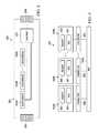
- FIG. 1is a block diagram of an example of an Information Handling System (IHS) design having a plurality of “trays” (modules or baseboards), each tray having a plurality of system-on-chip (SoC) nodes according to some embodiments.
- IHSInformation Handling System
- FIG. 2is a block diagram of an example of IHS sled design having a plurality of “sleds” (modules or baseboards), each sled having a plurality of SoC nodes according to some embodiments.
- FIG. 3is a block diagram of an example of tray or sled components according to some embodiments.
- FIG. 5is a block diagram of an architectural example of an integrated management controller (iMC) according to some embodiments.
- iMCintegrated management controller
- FIG. 7is a block diagram illustrating an example of an Information Handling System (IHS) configured to implement according to some embodiments.
- IHSInformation Handling System
- IPMIIntelligent Platform Management Interface
- IHSInformation Handling System
- BMCbaseboard management controller
- the IPMI specificationdefines standardized, abstracted interfaces to the platform management subsystem.
- the BMCis the heart of the IPMI architecture and provides the intelligence behind intelligent platform management—autonomous monitoring and recovery features implemented directly in platform management hardware and firmware.
- a problem with providing baseboard management systems in the aforementioned environmentsis providing these features without growing cost and/or complexity.
- Existing solutions to this probleminclude deploying full IPMI instances in each node—thus requiring multiple higher cost SOCs to support the full IPMI stack and complexity by making system vendors support yet additional IPMI stacks.
- the systems and methods described hereinprovide an architecture and design for efficiently distributing the baseboard management operations across multiple node management circuits and a sled or tray BMC.
- a management interfacemay be partitioned between node logic/firmware and tray/sled BMC or chassis level manager firmware in such a way as to lower overall cost and complexity without sacrificing desirable features.
- these systems and methodsmay effectively provide a discrete BMC on each node—although a full-featured IPMI stack does not need to be physically replicated in each such node—and then consolidate IPMI operations for all nodes via a low pin-count interface.
- references within the specification to “one embodiment,” “an embodiment,” “embodiments,” or “one or more embodiments”are intended to indicate that a particular feature, structure, component, or characteristic described in connection with the embodiment is included in at least one embodiment of the present disclosure.
- the appearance of such phrases in various places within the specificationare not necessarily all referring to the same embodiment, nor are separate or alternative embodiments mutually exclusive of other embodiments.
- various featuresare described which may be exhibited by some embodiments and not by others.
- various requirementsare described which may be requirements for some embodiments but not other embodiments.
- FIG. 1is a block diagram of an example of an Information Handling System (IHS) design having a plurality of “trays” (modules or baseboards), each tray having a plurality of system-on-chip (SoC) nodes.
- tray design 100may include a plurality of trays 101 A-N, each of which may be individually removable from the IHS (not shown).
- Each of trays 101 A-Nmay have a single “baseboard” that a number of SOC-based server nodes may be plugged into.
- SOC node 103is coupled to tray 102 N, and empty tray connector or slot 104 is available to receive another SOC node on that same tray.
- Each of trays 101 A-Nalso has a corresponding consolidation network switch and tray BMCs (or simply “BMCs”) 102 A-N.
- An IHS' chassis having tray design 100may further include common power module(s) and/or fan(s) to cool the entire chassis.
- Each tray-level BMC 102 A-Nmay be configured to consolidate information sent to and received from chassis-level sensors, chassis power and fan control, sensors from each of the SOC nodes (e.g., CPU temperature and memory sensors), serial console from each SOC node, host Basic I/O System (BIOS)/software interface from each SOC node, and/or logs from each SOC node.
- Each one of the SOC nodes on each of trays 101 A-Nmay implement its own integrated management controller (iMC; discussed for example in connection with FIG. 4 ), which communicates with BMCs 102 A-N.
- each of the plurality of IMCsmay be configured to implement a first IPMI stack having a simpler architecture than a second IPMI stack implemented by each of BMCs 102 A-N, as described in more detail below.
- two or more of BMCs that would typically be assigned to different trays or sledsmay instead be associated with two or more trays or sleds, or the entire IHS chassis (“chassis BMC”).
- FIG. 3is a block diagram of an example of tray or sled components 300 .
- each of SOC nodes 103 A-N of tray 101 Aincludes SOC logic 301 and memory 302 .
- Connector 303provides communications between each of nodes 203 A-N and BMC 102 A.
- SOC logic 301may implement iMC with a reduced IPMI stack while BMC 102 A implements more advanced or sophisticated IPMI operations (e.g., a full IPMI stack).
- FIG. 4is a block diagram of an example of a distributed baseboard management system 400 .
- SOC 103 Aalso includes SOC logic 301 and memory 302 .
- SOC logicincludes iMC microcontroller 401 , universal asynchronous receiver/transmitter (UART) interface 402 , IPMI host interface 403 , and sensor interface 404 .
- BMC 102 / 202includes BMC microcontroller 406 , memory 407 , and field-programmable gate array (FPGA) 408 .
- iMC 103 A and BMC 102 / 202are coupled to each other via interconnect bus 405 .
- iMC 401may include any management hardware interfaces that BIOS and Operating System (OS) software expects to find, including, for example, a serial console UART, IPMI Host Interface instances for both BIOS and OS (e.g., Keyboard Controller Style (KCS) interface), as well as access to node-level sensors (e.g., CPU temperature, CPU health, memory temperature, memory health, etc).
- OSOperating System
- iMC 401may include a small node-level micro-controller that interfaces the node management logic provided by components 402 - 404 via a management interconnect that coupled that logic with BMC 102 / 202 and/or a chassis level manager.
- each iMC 401is relatively small compared to the cost of BMC 102 / 202 because the functionality and amount memory needed by each iMC is relatively small compared to a more full-featured BMC.
- iMC 401may be configured to: (a) read outgoing data from node UART 402 and host Interface 403 , packetize it and send it out the management interconnect (e.g., without much or any processing); (b) read incoming data on the management interconnect, and write to UART 402 and host interface 403 (e.g., without much or any processing); and (c) scan internal SOC hardware logic and implement a relatively simple but intelligent sensor interface that BMC 102 / 202 or the chassis level manager can use to read SOC sensors 404 .
- BMC 102 / 202may be configured to implement the consolidating management control for the entire sled, tray, or chassis, at least in part, through the use of a suitable management transport protocol, such as, for example, the Distributed Management Task Force (DMTF) Management Component Transport Protocol (MCTP) standard.
- DMTFDistributed Management Task Force
- MCTPManagement Component Transport Protocol
- Thismay include, for instance, implementing an interface to the Management Interconnect for each node by FPGA 408 ; but may alternatively use any other suitable aggregation logic or circuit.
- this Sled/Tray BMC 102 / 202may be configured to: (a) run multiple copies of the IPMI stack (one for each of nodes 103 A-N), getting data from each node iMC that provides encapsulation and decapsulation of MCTP packets; (b) provide IPMI processing, data formatting, logging, state machines, event filtering, and external interfaces (including serial over LAN) associated with IPMI such as Sensor Read/Write, System Event Log (SEL) logging (with sensor capabilities abstracted from iMC), Sensor Data Record (SDR) functionality, sled/tray/chassis-level field replaceable unit (FRU) management, Platform Event Filtering, Serial Over Local Area Network (LAN; with serial data abstracted from iMC), IPMI over LAN and IPMI
- FIG. 5is a block diagram of an architectural example of iMC 500 according to some embodiments.
- sensor driver 501is in communication with sensor interface 404 and sensor monitoring service 502 , which in turn is coupled to Platform Level Data Model (PLDM) to management transport protocol mapper 503 (e.g., an MCTP mapper).
- PLDMPlatform Level Data Model
- Host interface device driver 503e.g., a KCS device driver, etc.
- IPMI host interface message relay service 505e.g., a KCS message relay service, etc.
- IPMI-to-management transport protocol mapper 506e.g., an IPMI to MCTP mapper, etc.
- UART driver 507is in communication with UART interface 403 and with serial relay service 508 , which in turn is coupled to serial-to-management transport protocol mapper 509 (e.g. a serial-to-MCTP mapper, etc.).
- serial-to-management transport protocol mapper 509e.g. a serial-to-MCTP mapper, etc.
- Each of PLDM-to-MCTP mapper 503 , IPMI-to-MCTP mapper 506 , and serial-to-MCTP mapper 509is coupled to MCTP interface 510 , which in turn is coupled to interconnect bus link 511 .
- interconnect bus link 511may be coupled to bus 405 and it may be implemented using the Enhanced Serial Peripheral Interface (eSPI) specification, Inter-Integrated Circuit (I 2 C) bus, Universal Serial Bus (USB), or Ethernet links.
- eSPIEnhanced Serial Peripheral Interface
- I 2 CInter-Integrated Circuit
- USBUniversal Serial Bus
- interconnect bus link 511may have a small pin count so that it may be run through connectors (e.g., midplane connector 204 ), without causing the BMC pin-count to be high.
- iMC architecture 500may be designed as a less-featured software stack an iMC 500 is capable of driving to capture and encapsulate data.
- iMC architecture 500may be configured to: (a) read/write data from/to UART 402 and Host Interface 403 ; (b) read/write data to/from management interconnect bus 405 ; (c) provide an abstracted view of node sensors 404 so that a tray/sled/chassis-level BMC can read the sensors (that is, iMC 500 does not perform heavy processing or interpreting of data—but only packaging and moving); (d) and relay data to mappers 503 , 506 , and 509 that wrap or encapsulate the data into standard management transport packets. Payload types are transported via MCTP interface 510 , which is a very lightweight, efficient wrapper protocol that allows payloads to be moved across various interconnects.
- FIG. 6is a block diagram of an architectural example of BMC 600 according to some embodiments.
- BMC architecture 600includes interconnect bus link 601 coupled to bus 405 (e.g., eSPI, I 2 C, USB, Ethernet, etc.), MCTP interface 602 , MCTP-to-PLDM decapsulator 603 , MCTP-to-IPMI decapsulator 605 , and MCTP-to-Serial decapsulator 607 .
- MTCP decapsulators 603 , 605 , and 607are coupled to sensor interface 604 , host interface 606 (e.g., a KCS interface), and serial interface 608 , respectively.
- Interfaces 604 , 606 , and 608are coupled to IPMI logic 609 , which in some cases may implement a full-featured IPMI circuit and/or instructions.
- IPMI logic 609may create a corresponding IPMI instance for each iMC that is being serviced by BMC architecture 600 , which contains the transport logic for application handling. IPMI logic 609 reads MCTP packets from the bus and routes them to appropriate instances for application level servicing. Also, IPMI logic 609 writes transport data from applications to the interconnect bus after MCTP encapsulation. Accordingly, the heavy lift operations are contained at the sled/tray/chassis BMC level, as opposed the iMC level.
- FIG. 7is a block diagram illustrating an example of an IHS configured to perform baseboard management with distributed intelligence in multi-node platforms according to some embodiments.
- tray IHS design 100 or sled IHS design 200may be implemented within IHS 700 .
- IHS 700includes one or more CPUs 702 .
- IHS 700may be a single-processor system including one CPU 702 , or a multi-processor system including two or more CPUs 702 (e.g., two, four, eight, or any other suitable number).
- CPU(s) 702may include any processor capable of executing program instructions.
- CPU(s) 702may be general-purpose or embedded processors implementing any of a variety of instruction set architectures (ISAs), such as the x86, POWERPC®, ARM®, SPARC®, or MIPS® ISAs, or any other suitable ISA. In multi-processor systems, each of CPU(s) 702 may commonly, but not necessarily, implement the same ISA.
- a motherboardconfigured to provide structural support, power, and electrical connectivity between the various aforementioned components. Such a motherboard may include multiple connector sockets in various configurations, adapted to receive pluggable circuit cards, component chip packages, etc.
- Northbridge controller 704may be configured to coordinate I/O traffic between CPU(s) 702 and other components.
- northbridge controller 704is coupled to graphics device(s) 708 (e.g., one or more video cards or adaptors, etc.) via graphics bus 710 (e.g., an Accelerated Graphics Port or AGP bus, a Peripheral Component Interconnect or PCI bus, etc.).
- Northbridge controller 704is also coupled to system memory 712 via memory bus 714 .
- Memory 712may be configured to store program instructions and/or data accessible by CPU(s) 702 .
- memory 712may be implemented using any suitable memory technology, such as static RAM (SRAM), synchronous dynamic RAM (SDRAM), nonvolatile/Flash-type memory, or any other type of memory.
- Northbridge controller 704is coupled to southbridge controller or chipset 716 via internal bus 718 .
- southbridge controller 716may be configured to handle various of computing device 700 ′s I/O operations, and it may provide interfaces such as, for instance, Universal Serial Bus (USB), audio, serial, parallel, Ethernet, etc., via port(s), pin(s), and/or adapter(s) 732 over bus 734 .
- southbridge controller 716may be configured to allow data to be exchanged between computing device 700 and other devices, such as other IHSs attached to a network.
- southbridge controller 716may support communication via wired or wireless general data networks, such as any suitable type of Ethernet network, for example; via telecommunications/telephony networks such as analog voice networks or digital fiber communications networks; via storage area networks such as Fiber Channel SANs; or via any other suitable type of network and/or protocol.
- general data networkssuch as any suitable type of Ethernet network, for example; via telecommunications/telephony networks such as analog voice networks or digital fiber communications networks; via storage area networks such as Fiber Channel SANs; or via any other suitable type of network and/or protocol.
- Southbridge controller 716may also enable connection to one or more keyboards, keypads, touch screens, scanning devices, voice or optical recognition devices, or any other devices suitable for entering or retrieving data. Multiple I/O devices may be present in computing device 700 . In some embodiments, I/O devices may be separate from IHS 700 and may interact with IHS 700 through a wired or wireless connection. As shown, southbridge controller 716 is further coupled to one or more PCI devices 720 (e.g., modems, network cards, sound cards, video cards, etc.) via PCI bus 732 . Southbridge controller 716 is also coupled to BIOS 724 , Super I/O Controller 726 , and BMC 728 via Low Pin Count (LPC) bus 270 . In some cases, BMC 728 may be used as one of tray BMCs 102 A-N, sled BMCs 202 , or a chassis BMC.
- PCI devices 720e.g., modems, network cards, sound cards, video cards, etc.
- BIOS 724includes non-volatile memory having program instructions stored thereon. Those instructions may be usable CPU(s) 702 to initialize and test other hardware components and/or to load an Operating System (OS) onto computing device 700 . As such, BIOS 724 may include a firmware interface that allows CPU(s) 702 to load and execute certain firmware, as described in more detail below. In some cases, such firmware may include program code that is compatible with the Unified Extensible Firmware Interface (UEFI) specification, although other types of firmware may be used.
- UEFIUnified Extensible Firmware Interface
- BMC controller 728may include non-volatile memory having program instructions stored thereon that are usable by CPU(s) 702 to enable remote management of IHS 700 .
- BMC controller 728may enable a user to discover, configure, and manage BMC controller 728 , setup configuration options, resolve and administer hardware or software problems, etc.
- BMC controller 728may include one or more firmware volumes, each volume having one or more firmware files used by the BIOS' firmware interface to initialize and test components of computing device 700 .
- Super I/O Controller 726combines interfaces for a variety of lower bandwidth or low data rate devices. Those devices may include, for example, floppy disks, parallel ports, keyboard and mouse, temperature sensor and fan speed monitoring, etc.
- the super I/O controller 726may be coupled to the one or more upstream sensors 706 and to the one or more downstream sensors 708 .
- IHS 700may be configured to access different types of computer-accessible media separate from memory 712 .
- a computer-accessible memory devicemay include any tangible, non-transitory storage media or memory media such as electronic, magnetic, or optical media—e.g., magnetic disk, a hard drive, a CD/DVD-ROM, a Flash memory, etc.—coupled to IHS 700 via northbridge controller 704 and/or southbridge controller 716 .
- tangible and “non-transitory,” as used herein,are intended to describe a computer-readable storage medium (or “memory”) excluding propagating electromagnetic signals; but are not intended to otherwise limit the type of physical computer-readable storage device that is encompassed by the phrase computer-readable medium or memory.
- non-transitory computer readable medium” or “tangible memory”are intended to encompass types of storage devices that do not necessarily store information permanently, including, for example, RAM.
- Program instructions and data stored on a tangible computer-accessible storage medium in non-transitory formmay afterwards be transmitted by transmission media or signals such as electrical, electromagnetic, or digital signals, which may be conveyed via a communication medium such as a network and/or a wireless link.
- IHS 700is merely illustrative and is not intended to limit the scope of the disclosure described herein.
- any computer system and/or devicemay include any combination of hardware or software capable of performing certain operations described herein.
- IHS 700is illustrated following an Intel® architecture, various systems and methods described herein may be adapted to work with any other chipset and/or BMC configuration.
- the operations performed by the illustrated componentsmay, in some embodiments, be performed by fewer components or distributed across additional components. Similarly, in other embodiments, the operations of some of the illustrated components may not be performed and/or other additional operations may be available.
- IHS 700 of FIG. 7is only an example of a system in which the present embodiments may be utilized. Indeed, the present embodiments may be used in various other types of electronic devices.
- the baseboard management systems and methods with distributed intelligence for multi-node platforms described hereinmay provide simplicity of node management logic (via iMCs) without a heavy IPMI stack that SOC vendors have to buy or license from third parties, but rather with a simple stack that is easy to define, easy to implement, with small silicon footprint and internal SOC RAM, without adding significant costs to the SOC.
- the systems and methodsmay also provide increase flexibility by putting the entire complex IPMI stack and all user interfaces in a consolidated tray/sled BMC or chassis level manager, which has plenty of RAM, FLASH, performance, and can leverage platform vendor implementations—all of which make the overall solution less complex.
- host software on each SOC node and the remote software executed by the tray/sled/chassis BMCmay each run tools that are indifferent to the merging of service traffic as MCTP over various physical interfaces.
- these systems and methodsavoid problems that would otherwise arise if a full BMC were implemented on all nodes, and a separate, consolidation BMC is used to manage all full-features node BMCs, including, by not limited to: added costs to SOCs by increasing internal RAM size significantly, added complexity due to forcing vendors to integrate IPMI in their SOCs, added operator complexity by forcing direct management of all BMCs. Additionally or alternatively, these systems and methods overcome other problems that would surface if existing hardware interfaces were run from each of a plurality of SOCs to a single BMC, including, but not limited to, large pin counts that are not feasible for designs with many nodes behind one consolidating BMC, where interconnects pass through connectors. Additionally or alternatively, these systems and methods avoid problems that would otherwise arise if only partial management functionality, including, but not limited to, the lack of host interfaces and/or serial consoles. (e.g., no host interfaces).
- one or more of the methodsmay be embodied in a memory device or computer readable medium containing computer readable code such that a series of functional processes are performed when the computer readable code is executed on a computing device.
- certain steps of the methodsare combined, performed simultaneously or in a different order, or perhaps omitted, without deviating from the scope of the disclosure.
- the method blocksare described and illustrated in a particular sequence, use of a specific sequence of functional processes represented by the blocks is not meant to imply any limitations on the disclosure. Changes may be made with regards to the sequence of processes without departing from the scope of the present disclosure. Use of a particular sequence is therefore, not to be taken in a limiting sense, and the scope of the present disclosure is defined only by the appended claims.
- These computer program instructionsmay be provided to a processor of a general purpose computer, special purpose computer, such as a service processor, or other programmable data processing apparatus to produce a machine, such that the instructions, which execute via the processor of the computer or other programmable data processing apparatus, performs the method for implementing the functions/acts specified in the flowchart and/or block diagram block or blocks.
- aspects of the present disclosuremay be implemented using any combination of software, firmware or hardware. Accordingly, aspects of the present disclosure may take the form of an entirely hardware embodiment or an embodiment combining software (including firmware, resident software, micro-code, etc.) and hardware aspects that may all generally be referred to herein as a “circuit,” “module,” or “system.” Furthermore, aspects of the present disclosure may take the form of a computer program product embodied in one or more computer readable storage device(s) having computer readable program code embodied thereon. Any combination of one or more computer readable storage device(s) may be utilized.
- the computer readable storage devicemay be, for example, but not limited to, an electronic, magnetic, optical, electromagnetic, infrared, or semiconductor system, apparatus, or device, or any suitable combination of the foregoing. More specific examples (a non-exhaustive list) of the computer readable storage device would include the following: an electrical connection having one or more wires, a portable computer diskette, a hard disk, a random access memory (RAM), a read-only memory (ROM), an erasable programmable read-only memory (EPROM or Flash memory), an optical fiber, a portable compact disc read-only memory (CD-ROM), an optical storage device, a magnetic storage device, or any suitable combination of the foregoing.
- a computer readable storage devicemay be any tangible medium that can contain, or store a program for use by or in connection with an instruction execution system, apparatus, or device.
Landscapes
- Engineering & Computer Science (AREA)
- Theoretical Computer Science (AREA)
- General Engineering & Computer Science (AREA)
- Computer Hardware Design (AREA)
- Physics & Mathematics (AREA)
- General Physics & Mathematics (AREA)
- Mathematical Physics (AREA)
- Software Systems (AREA)
- Debugging And Monitoring (AREA)
- Computing Systems (AREA)
- Microelectronics & Electronic Packaging (AREA)
Abstract
Description
Claims (20)
Priority Applications (1)
| Application Number | Priority Date | Filing Date | Title |
|---|---|---|---|
| US14/625,676US9767067B2 (en) | 2015-02-19 | 2015-02-19 | Baseboard management systems and methods with distributed intelligence for multi-node platforms |
Applications Claiming Priority (1)
| Application Number | Priority Date | Filing Date | Title |
|---|---|---|---|
| US14/625,676US9767067B2 (en) | 2015-02-19 | 2015-02-19 | Baseboard management systems and methods with distributed intelligence for multi-node platforms |
Publications (2)
| Publication Number | Publication Date |
|---|---|
| US20160246754A1 US20160246754A1 (en) | 2016-08-25 |
| US9767067B2true US9767067B2 (en) | 2017-09-19 |
Family
ID=56689924
Family Applications (1)
| Application Number | Title | Priority Date | Filing Date |
|---|---|---|---|
| US14/625,676Active2036-03-19US9767067B2 (en) | 2015-02-19 | 2015-02-19 | Baseboard management systems and methods with distributed intelligence for multi-node platforms |
Country Status (1)
| Country | Link |
|---|---|
| US (1) | US9767067B2 (en) |
Cited By (1)
| Publication number | Priority date | Publication date | Assignee | Title |
|---|---|---|---|---|
| US11171788B2 (en) | 2019-06-03 | 2021-11-09 | Dell Products L.P. | System and method for shared end device authentication for in-band requests |
Families Citing this family (22)
| Publication number | Priority date | Publication date | Assignee | Title |
|---|---|---|---|---|
| US9811481B2 (en)* | 2015-04-30 | 2017-11-07 | American Megatrends, Inc. | Distributed intelligent platform management interface (D-IPMI) system and method thereof |
| US11983138B2 (en) | 2015-07-26 | 2024-05-14 | Samsung Electronics Co., Ltd. | Self-configuring SSD multi-protocol support in host-less environment |
| CN105488009B (en)* | 2015-12-03 | 2018-07-06 | 英业达科技有限公司 | The reading/writing method and read/write system of a kind of FRU |
| US10664433B2 (en)* | 2016-06-30 | 2020-05-26 | Intel Corporation | Innovative high speed serial controller testing |
| US10034407B2 (en)* | 2016-07-22 | 2018-07-24 | Intel Corporation | Storage sled for a data center |
| US11461258B2 (en) | 2016-09-14 | 2022-10-04 | Samsung Electronics Co., Ltd. | Self-configuring baseboard management controller (BMC) |
| US10210123B2 (en) | 2016-07-26 | 2019-02-19 | Samsung Electronics Co., Ltd. | System and method for supporting multi-path and/or multi-mode NMVe over fabrics devices |
| US10372659B2 (en) | 2016-07-26 | 2019-08-06 | Samsung Electronics Co., Ltd. | Multi-mode NMVE over fabrics devices |
| US11144496B2 (en) | 2016-07-26 | 2021-10-12 | Samsung Electronics Co., Ltd. | Self-configuring SSD multi-protocol support in host-less environment |
| US10346041B2 (en) | 2016-09-14 | 2019-07-09 | Samsung Electronics Co., Ltd. | Method for using BMC as proxy NVMeoF discovery controller to provide NVM subsystems to host |
| US10616348B2 (en)* | 2016-09-13 | 2020-04-07 | American Megatrends International, Llc | System and method for providing multiple IPMI serial over LAN (SOL) sessions in management controller stack |
| US10489601B2 (en)* | 2017-06-08 | 2019-11-26 | American Megatrends International, Llc | Encrypted extended system event log |
| US10860305B1 (en)* | 2017-09-29 | 2020-12-08 | Amazon Technologies, Inc. | Secure firmware deployment |
| US10783109B2 (en)* | 2018-10-24 | 2020-09-22 | Dell Products, L.P. | Device management messaging protocol proxy |
| US10831467B2 (en)* | 2018-10-25 | 2020-11-10 | American Megatrends International, Llc | Techniques of updating host device firmware via service processor |
| US11592805B2 (en)* | 2020-03-31 | 2023-02-28 | Lenovo Enterprise Solutions (Singapore) Pte. Ltd. | Computing device expansion modules and control of their operation based on temperature |
| CN115237827A (en)* | 2021-04-23 | 2022-10-25 | 华为技术有限公司 | A management system, processing chip, device, equipment and method |
| US11604756B1 (en)* | 2021-10-15 | 2023-03-14 | Dell Products, L.P. | High-speed, out-of-band (OOB) management links for inter-baseboard management controller (BMC) communications in high performance computing (HPC) platforms |
| US11669151B1 (en)* | 2021-12-20 | 2023-06-06 | Dell Products L.P. | Method for dynamic feature enablement based on power budgeting forecasting |
| US12001350B2 (en)* | 2022-10-07 | 2024-06-04 | Oracle International Corporation | Dynamically configurable motherboard |
| US20240143474A1 (en)* | 2022-10-27 | 2024-05-02 | American Megatrends International, Llc | System and method for dynamic sensors support in ipmi stack |
| CN118939600A (en)* | 2024-07-19 | 2024-11-12 | 广州磐玉科技有限公司 | Field programmable gate array structure for realizing out-of-band bridging, out-of-band bridging system, method and server |
- 2015
- 2015-02-19USUS14/625,676patent/US9767067B2/enactiveActive
Cited By (1)
| Publication number | Priority date | Publication date | Assignee | Title |
|---|---|---|---|---|
| US11171788B2 (en) | 2019-06-03 | 2021-11-09 | Dell Products L.P. | System and method for shared end device authentication for in-band requests |
Also Published As
| Publication number | Publication date |
|---|---|
| US20160246754A1 (en) | 2016-08-25 |
Similar Documents
| Publication | Publication Date | Title |
|---|---|---|
| US9767067B2 (en) | Baseboard management systems and methods with distributed intelligence for multi-node platforms | |
| US10778521B2 (en) | Reconfiguring a server including a reconfigurable adapter device | |
| EP3242217B1 (en) | Systems and methods for flexible hdd/ssd storage support | |
| US10223313B2 (en) | Scalable pooled NVMe storage box that comprises a PCIe switch further connected to one or more switches and switch ports | |
| US9197596B2 (en) | System and method to use common addresses on a management controller without conflict | |
| US9678912B2 (en) | Pass-through converged network adaptor (CNA) using existing ethernet switching device | |
| CN104838373B (en) | Apparatus, system, and method for single microcontroller based management of multiple compute nodes | |
| US20160342437A1 (en) | Data path failover method for sr-iov capable ethernet controller | |
| US11411753B2 (en) | Adding network controller sideband interface (NC-SI) sideband and management to a high power consumption device | |
| US11218543B2 (en) | System and method to configure, manage, and monitor stacking of Ethernet devices in a software defined network | |
| US10911405B1 (en) | Secure environment on a server | |
| US11003607B2 (en) | NVMF storage to NIC card coupling over a dedicated bus | |
| US10425287B2 (en) | Systems and methods for network topology discovery | |
| US9804980B2 (en) | System management through direct communication between system management controllers | |
| US9654421B2 (en) | Providing real-time interrupts over ethernet | |
| US20200203898A1 (en) | System and Method for Remote Management of Network Interface Peripherals | |
| CN108334421A (en) | System recovery using WO L | |
| US9092404B2 (en) | System and method to remotely recover from a system halt during system initialization | |
| WO2025138695A1 (en) | Computing device, management controller, and data processing method | |
| US10075398B2 (en) | Systems and methods for enabling a host system to use a network interface of a management controller | |
| US11088910B2 (en) | Efficient method for managing and adding systems within a solution | |
| US20190034215A1 (en) | Generating host groups in an information handling system | |
| US10785118B2 (en) | Systems and methods for network topology validation | |
| US12028276B2 (en) | Transport control word architecture for virtual port mirroring | |
| WO2023060928A1 (en) | Method, apparatus, and system for communicating with pcie device |
Legal Events
| Date | Code | Title | Description |
|---|---|---|---|
| AS | Assignment | Owner name:DELL PRODUCTS, L.P., TEXAS Free format text:ASSIGNMENT OF ASSIGNORS INTEREST;ASSIGNORS:JREJI, ELIE ANTOUN;LAMBERT, TIMOTHY M.;VANCIL, PAUL W.;AND OTHERS;SIGNING DATES FROM 20150217 TO 20150218;REEL/FRAME:034981/0623 | |
| AS | Assignment | Owner name:BANK OF NEW YORK MELLON TRUST COMPANY, N.A., AS NOTES COLLATERAL AGENT, TEXAS Free format text:SUPPLEMENT TO PATENT SECURITY AGREEMENT (NOTES);ASSIGNORS:DELL PRODUCTS L.P.;DELL SOFTWARE INC.;COMPELLENT TECHNOLOGIES, INC;AND OTHERS;REEL/FRAME:035860/0878 Effective date:20150602 Owner name:BANK OF AMERICA, N.A., AS COLLATERAL AGENT, NORTH CAROLINA Free format text:SUPPLEMENT TO PATENT SECURITY AGREEMENT (TERM LOAN);ASSIGNORS:DELL PRODUCTS L.P.;DELL SOFTWARE INC.;COMPELLENT TECHNOLOGIES, INC.;AND OTHERS;REEL/FRAME:035860/0797 Effective date:20150602 Owner name:BANK OF AMERICA, N.A., AS ADMINISTRATIVE AGENT, NORTH CAROLINA Free format text:SUPPLEMENT TO PATENT SECURITY AGREEMENT (ABL);ASSIGNORS:DELL PRODUCTS L.P.;DELL SOFTWARE INC.;COMPELLENT TECHNOLOGIES, INC.;AND OTHERS;REEL/FRAME:035858/0612 Effective date:20150602 Owner name:BANK OF AMERICA, N.A., AS COLLATERAL AGENT, NORTH Free format text:SUPPLEMENT TO PATENT SECURITY AGREEMENT (TERM LOAN);ASSIGNORS:DELL PRODUCTS L.P.;DELL SOFTWARE INC.;COMPELLENT TECHNOLOGIES, INC.;AND OTHERS;REEL/FRAME:035860/0797 Effective date:20150602 Owner name:BANK OF NEW YORK MELLON TRUST COMPANY, N.A., AS NO Free format text:SUPPLEMENT TO PATENT SECURITY AGREEMENT (NOTES);ASSIGNORS:DELL PRODUCTS L.P.;DELL SOFTWARE INC.;COMPELLENT TECHNOLOGIES, INC;AND OTHERS;REEL/FRAME:035860/0878 Effective date:20150602 Owner name:BANK OF AMERICA, N.A., AS ADMINISTRATIVE AGENT, NO Free format text:SUPPLEMENT TO PATENT SECURITY AGREEMENT (ABL);ASSIGNORS:DELL PRODUCTS L.P.;DELL SOFTWARE INC.;COMPELLENT TECHNOLOGIES, INC.;AND OTHERS;REEL/FRAME:035858/0612 Effective date:20150602 | |
| AS | Assignment | Owner name:SECUREWORKS, INC., GEORGIA Free format text:RELEASE OF REEL 035858 FRAME 0612 (ABL);ASSIGNOR:BANK OF AMERICA, N.A., AS ADMINISTRATIVE AGENT;REEL/FRAME:040017/0067 Effective date:20160907 Owner name:STATSOFT, INC., TEXAS Free format text:RELEASE OF REEL 035858 FRAME 0612 (ABL);ASSIGNOR:BANK OF AMERICA, N.A., AS ADMINISTRATIVE AGENT;REEL/FRAME:040017/0067 Effective date:20160907 Owner name:COMPELLENT TECHNOLOGIES, INC., MINNESOTA Free format text:RELEASE OF REEL 035858 FRAME 0612 (ABL);ASSIGNOR:BANK OF AMERICA, N.A., AS ADMINISTRATIVE AGENT;REEL/FRAME:040017/0067 Effective date:20160907 Owner name:DELL PRODUCTS L.P., TEXAS Free format text:RELEASE OF REEL 035858 FRAME 0612 (ABL);ASSIGNOR:BANK OF AMERICA, N.A., AS ADMINISTRATIVE AGENT;REEL/FRAME:040017/0067 Effective date:20160907 Owner name:DELL SOFTWARE INC., CALIFORNIA Free format text:RELEASE OF REEL 035858 FRAME 0612 (ABL);ASSIGNOR:BANK OF AMERICA, N.A., AS ADMINISTRATIVE AGENT;REEL/FRAME:040017/0067 Effective date:20160907 | |
| AS | Assignment | Owner name:COMPELLENT TECHNOLOGIES, INC., MINNESOTA Free format text:RELEASE OF REEL 035860 FRAME 0878 (NOTE);ASSIGNOR:BANK OF NEW YORK MELLON TRUST COMPANY, N.A., AS COLLATERAL AGENT;REEL/FRAME:040027/0158 Effective date:20160907 Owner name:DELL SOFTWARE INC., CALIFORNIA Free format text:RELEASE OF REEL 035860 FRAME 0878 (NOTE);ASSIGNOR:BANK OF NEW YORK MELLON TRUST COMPANY, N.A., AS COLLATERAL AGENT;REEL/FRAME:040027/0158 Effective date:20160907 Owner name:SECUREWORKS, INC., GEORGIA Free format text:RELEASE OF REEL 035860 FRAME 0797 (TL);ASSIGNOR:BANK OF AMERICA, N.A., AS COLLATERAL AGENT;REEL/FRAME:040028/0551 Effective date:20160907 Owner name:DELL PRODUCTS L.P., TEXAS Free format text:RELEASE OF REEL 035860 FRAME 0797 (TL);ASSIGNOR:BANK OF AMERICA, N.A., AS COLLATERAL AGENT;REEL/FRAME:040028/0551 Effective date:20160907 Owner name:STATSOFT, INC., TEXAS Free format text:RELEASE OF REEL 035860 FRAME 0878 (NOTE);ASSIGNOR:BANK OF NEW YORK MELLON TRUST COMPANY, N.A., AS COLLATERAL AGENT;REEL/FRAME:040027/0158 Effective date:20160907 Owner name:COMPELLENT TECHNOLOGIES, INC., MINNESOTA Free format text:RELEASE OF REEL 035860 FRAME 0797 (TL);ASSIGNOR:BANK OF AMERICA, N.A., AS COLLATERAL AGENT;REEL/FRAME:040028/0551 Effective date:20160907 Owner name:DELL SOFTWARE INC., CALIFORNIA Free format text:RELEASE OF REEL 035860 FRAME 0797 (TL);ASSIGNOR:BANK OF AMERICA, N.A., AS COLLATERAL AGENT;REEL/FRAME:040028/0551 Effective date:20160907 Owner name:STATSOFT, INC., TEXAS Free format text:RELEASE OF REEL 035860 FRAME 0797 (TL);ASSIGNOR:BANK OF AMERICA, N.A., AS COLLATERAL AGENT;REEL/FRAME:040028/0551 Effective date:20160907 Owner name:SECUREWORKS, INC., GEORGIA Free format text:RELEASE OF REEL 035860 FRAME 0878 (NOTE);ASSIGNOR:BANK OF NEW YORK MELLON TRUST COMPANY, N.A., AS COLLATERAL AGENT;REEL/FRAME:040027/0158 Effective date:20160907 Owner name:DELL PRODUCTS L.P., TEXAS Free format text:RELEASE OF REEL 035860 FRAME 0878 (NOTE);ASSIGNOR:BANK OF NEW YORK MELLON TRUST COMPANY, N.A., AS COLLATERAL AGENT;REEL/FRAME:040027/0158 Effective date:20160907 | |
| AS | Assignment | Owner name:CREDIT SUISSE AG, CAYMAN ISLANDS BRANCH, AS COLLATERAL AGENT, NORTH CAROLINA Free format text:SECURITY AGREEMENT;ASSIGNORS:ASAP SOFTWARE EXPRESS, INC.;AVENTAIL LLC;CREDANT TECHNOLOGIES, INC.;AND OTHERS;REEL/FRAME:040134/0001 Effective date:20160907 Owner name:THE BANK OF NEW YORK MELLON TRUST COMPANY, N.A., AS NOTES COLLATERAL AGENT, TEXAS Free format text:SECURITY AGREEMENT;ASSIGNORS:ASAP SOFTWARE EXPRESS, INC.;AVENTAIL LLC;CREDANT TECHNOLOGIES, INC.;AND OTHERS;REEL/FRAME:040136/0001 Effective date:20160907 Owner name:CREDIT SUISSE AG, CAYMAN ISLANDS BRANCH, AS COLLAT Free format text:SECURITY AGREEMENT;ASSIGNORS:ASAP SOFTWARE EXPRESS, INC.;AVENTAIL LLC;CREDANT TECHNOLOGIES, INC.;AND OTHERS;REEL/FRAME:040134/0001 Effective date:20160907 Owner name:THE BANK OF NEW YORK MELLON TRUST COMPANY, N.A., A Free format text:SECURITY AGREEMENT;ASSIGNORS:ASAP SOFTWARE EXPRESS, INC.;AVENTAIL LLC;CREDANT TECHNOLOGIES, INC.;AND OTHERS;REEL/FRAME:040136/0001 Effective date:20160907 | |
| STCF | Information on status: patent grant | Free format text:PATENTED CASE | |
| CC | Certificate of correction | ||
| AS | Assignment | Owner name:THE BANK OF NEW YORK MELLON TRUST COMPANY, N.A., T Free format text:SECURITY AGREEMENT;ASSIGNORS:CREDANT TECHNOLOGIES, INC.;DELL INTERNATIONAL L.L.C.;DELL MARKETING L.P.;AND OTHERS;REEL/FRAME:049452/0223 Effective date:20190320 Owner name:THE BANK OF NEW YORK MELLON TRUST COMPANY, N.A., TEXAS Free format text:SECURITY AGREEMENT;ASSIGNORS:CREDANT TECHNOLOGIES, INC.;DELL INTERNATIONAL L.L.C.;DELL MARKETING L.P.;AND OTHERS;REEL/FRAME:049452/0223 Effective date:20190320 | |
| AS | Assignment | Owner name:THE BANK OF NEW YORK MELLON TRUST COMPANY, N.A., TEXAS Free format text:SECURITY AGREEMENT;ASSIGNORS:CREDANT TECHNOLOGIES INC.;DELL INTERNATIONAL L.L.C.;DELL MARKETING L.P.;AND OTHERS;REEL/FRAME:053546/0001 Effective date:20200409 | |
| MAFP | Maintenance fee payment | Free format text:PAYMENT OF MAINTENANCE FEE, 4TH YEAR, LARGE ENTITY (ORIGINAL EVENT CODE: M1551); ENTITY STATUS OF PATENT OWNER: LARGE ENTITY Year of fee payment:4 | |
| AS | Assignment | Owner name:WYSE TECHNOLOGY L.L.C., CALIFORNIA Free format text:RELEASE BY SECURED PARTY;ASSIGNOR:CREDIT SUISSE AG, CAYMAN ISLANDS BRANCH;REEL/FRAME:058216/0001 Effective date:20211101 Owner name:SCALEIO LLC, MASSACHUSETTS Free format text:RELEASE BY SECURED PARTY;ASSIGNOR:CREDIT SUISSE AG, CAYMAN ISLANDS BRANCH;REEL/FRAME:058216/0001 Effective date:20211101 Owner name:MOZY, INC., WASHINGTON Free format text:RELEASE BY SECURED PARTY;ASSIGNOR:CREDIT SUISSE AG, CAYMAN ISLANDS BRANCH;REEL/FRAME:058216/0001 Effective date:20211101 Owner name:MAGINATICS LLC, CALIFORNIA Free format text:RELEASE BY SECURED PARTY;ASSIGNOR:CREDIT SUISSE AG, CAYMAN ISLANDS BRANCH;REEL/FRAME:058216/0001 Effective date:20211101 Owner name:FORCE10 NETWORKS, INC., CALIFORNIA Free format text:RELEASE BY SECURED PARTY;ASSIGNOR:CREDIT SUISSE AG, CAYMAN ISLANDS BRANCH;REEL/FRAME:058216/0001 Effective date:20211101 Owner name:EMC IP HOLDING COMPANY LLC, TEXAS Free format text:RELEASE BY SECURED PARTY;ASSIGNOR:CREDIT SUISSE AG, CAYMAN ISLANDS BRANCH;REEL/FRAME:058216/0001 Effective date:20211101 Owner name:EMC CORPORATION, MASSACHUSETTS Free format text:RELEASE BY SECURED PARTY;ASSIGNOR:CREDIT SUISSE AG, CAYMAN ISLANDS BRANCH;REEL/FRAME:058216/0001 Effective date:20211101 Owner name:DELL SYSTEMS CORPORATION, TEXAS Free format text:RELEASE BY SECURED PARTY;ASSIGNOR:CREDIT SUISSE AG, CAYMAN ISLANDS BRANCH;REEL/FRAME:058216/0001 Effective date:20211101 Owner name:DELL SOFTWARE INC., CALIFORNIA Free format text:RELEASE BY SECURED PARTY;ASSIGNOR:CREDIT SUISSE AG, CAYMAN ISLANDS BRANCH;REEL/FRAME:058216/0001 Effective date:20211101 Owner name:DELL PRODUCTS L.P., TEXAS Free format text:RELEASE BY SECURED PARTY;ASSIGNOR:CREDIT SUISSE AG, CAYMAN ISLANDS BRANCH;REEL/FRAME:058216/0001 Effective date:20211101 Owner name:DELL MARKETING L.P., TEXAS Free format text:RELEASE BY SECURED PARTY;ASSIGNOR:CREDIT SUISSE AG, CAYMAN ISLANDS BRANCH;REEL/FRAME:058216/0001 Effective date:20211101 Owner name:DELL INTERNATIONAL, L.L.C., TEXAS Free format text:RELEASE BY SECURED PARTY;ASSIGNOR:CREDIT SUISSE AG, CAYMAN ISLANDS BRANCH;REEL/FRAME:058216/0001 Effective date:20211101 Owner name:DELL USA L.P., TEXAS Free format text:RELEASE BY SECURED PARTY;ASSIGNOR:CREDIT SUISSE AG, CAYMAN ISLANDS BRANCH;REEL/FRAME:058216/0001 Effective date:20211101 Owner name:CREDANT TECHNOLOGIES, INC., TEXAS Free format text:RELEASE BY SECURED PARTY;ASSIGNOR:CREDIT SUISSE AG, CAYMAN ISLANDS BRANCH;REEL/FRAME:058216/0001 Effective date:20211101 Owner name:AVENTAIL LLC, CALIFORNIA Free format text:RELEASE BY SECURED PARTY;ASSIGNOR:CREDIT SUISSE AG, CAYMAN ISLANDS BRANCH;REEL/FRAME:058216/0001 Effective date:20211101 Owner name:ASAP SOFTWARE EXPRESS, INC., ILLINOIS Free format text:RELEASE BY SECURED PARTY;ASSIGNOR:CREDIT SUISSE AG, CAYMAN ISLANDS BRANCH;REEL/FRAME:058216/0001 Effective date:20211101 | |
| AS | Assignment | Owner name:SCALEIO LLC, MASSACHUSETTS Free format text:RELEASE OF SECURITY INTEREST IN PATENTS PREVIOUSLY RECORDED AT REEL/FRAME (040136/0001);ASSIGNOR:THE BANK OF NEW YORK MELLON TRUST COMPANY, N.A., AS NOTES COLLATERAL AGENT;REEL/FRAME:061324/0001 Effective date:20220329 Owner name:EMC IP HOLDING COMPANY LLC (ON BEHALF OF ITSELF AND AS SUCCESSOR-IN-INTEREST TO MOZY, INC.), TEXAS Free format text:RELEASE OF SECURITY INTEREST IN PATENTS PREVIOUSLY RECORDED AT REEL/FRAME (040136/0001);ASSIGNOR:THE BANK OF NEW YORK MELLON TRUST COMPANY, N.A., AS NOTES COLLATERAL AGENT;REEL/FRAME:061324/0001 Effective date:20220329 Owner name:EMC CORPORATION (ON BEHALF OF ITSELF AND AS SUCCESSOR-IN-INTEREST TO MAGINATICS LLC), MASSACHUSETTS Free format text:RELEASE OF SECURITY INTEREST IN PATENTS PREVIOUSLY RECORDED AT REEL/FRAME (040136/0001);ASSIGNOR:THE BANK OF NEW YORK MELLON TRUST COMPANY, N.A., AS NOTES COLLATERAL AGENT;REEL/FRAME:061324/0001 Effective date:20220329 Owner name:DELL MARKETING CORPORATION (SUCCESSOR-IN-INTEREST TO FORCE10 NETWORKS, INC. AND WYSE TECHNOLOGY L.L.C.), TEXAS Free format text:RELEASE OF SECURITY INTEREST IN PATENTS PREVIOUSLY RECORDED AT REEL/FRAME (040136/0001);ASSIGNOR:THE BANK OF NEW YORK MELLON TRUST COMPANY, N.A., AS NOTES COLLATERAL AGENT;REEL/FRAME:061324/0001 Effective date:20220329 Owner name:DELL PRODUCTS L.P., TEXAS Free format text:RELEASE OF SECURITY INTEREST IN PATENTS PREVIOUSLY RECORDED AT REEL/FRAME (040136/0001);ASSIGNOR:THE BANK OF NEW YORK MELLON TRUST COMPANY, N.A., AS NOTES COLLATERAL AGENT;REEL/FRAME:061324/0001 Effective date:20220329 Owner name:DELL INTERNATIONAL L.L.C., TEXAS Free format text:RELEASE OF SECURITY INTEREST IN PATENTS PREVIOUSLY RECORDED AT REEL/FRAME (040136/0001);ASSIGNOR:THE BANK OF NEW YORK MELLON TRUST COMPANY, N.A., AS NOTES COLLATERAL AGENT;REEL/FRAME:061324/0001 Effective date:20220329 Owner name:DELL USA L.P., TEXAS Free format text:RELEASE OF SECURITY INTEREST IN PATENTS PREVIOUSLY RECORDED AT REEL/FRAME (040136/0001);ASSIGNOR:THE BANK OF NEW YORK MELLON TRUST COMPANY, N.A., AS NOTES COLLATERAL AGENT;REEL/FRAME:061324/0001 Effective date:20220329 Owner name:DELL MARKETING L.P. (ON BEHALF OF ITSELF AND AS SUCCESSOR-IN-INTEREST TO CREDANT TECHNOLOGIES, INC.), TEXAS Free format text:RELEASE OF SECURITY INTEREST IN PATENTS PREVIOUSLY RECORDED AT REEL/FRAME (040136/0001);ASSIGNOR:THE BANK OF NEW YORK MELLON TRUST COMPANY, N.A., AS NOTES COLLATERAL AGENT;REEL/FRAME:061324/0001 Effective date:20220329 Owner name:DELL MARKETING CORPORATION (SUCCESSOR-IN-INTEREST TO ASAP SOFTWARE EXPRESS, INC.), TEXAS Free format text:RELEASE OF SECURITY INTEREST IN PATENTS PREVIOUSLY RECORDED AT REEL/FRAME (040136/0001);ASSIGNOR:THE BANK OF NEW YORK MELLON TRUST COMPANY, N.A., AS NOTES COLLATERAL AGENT;REEL/FRAME:061324/0001 Effective date:20220329 | |
| AS | Assignment | Owner name:SCALEIO LLC, MASSACHUSETTS Free format text:RELEASE OF SECURITY INTEREST IN PATENTS PREVIOUSLY RECORDED AT REEL/FRAME (045455/0001);ASSIGNOR:THE BANK OF NEW YORK MELLON TRUST COMPANY, N.A., AS NOTES COLLATERAL AGENT;REEL/FRAME:061753/0001 Effective date:20220329 Owner name:EMC IP HOLDING COMPANY LLC (ON BEHALF OF ITSELF AND AS SUCCESSOR-IN-INTEREST TO MOZY, INC.), TEXAS Free format text:RELEASE OF SECURITY INTEREST IN PATENTS PREVIOUSLY RECORDED AT REEL/FRAME (045455/0001);ASSIGNOR:THE BANK OF NEW YORK MELLON TRUST COMPANY, N.A., AS NOTES COLLATERAL AGENT;REEL/FRAME:061753/0001 Effective date:20220329 Owner name:EMC CORPORATION (ON BEHALF OF ITSELF AND AS SUCCESSOR-IN-INTEREST TO MAGINATICS LLC), MASSACHUSETTS Free format text:RELEASE OF SECURITY INTEREST IN PATENTS PREVIOUSLY RECORDED AT REEL/FRAME (045455/0001);ASSIGNOR:THE BANK OF NEW YORK MELLON TRUST COMPANY, N.A., AS NOTES COLLATERAL AGENT;REEL/FRAME:061753/0001 Effective date:20220329 Owner name:DELL MARKETING CORPORATION (SUCCESSOR-IN-INTEREST TO FORCE10 NETWORKS, INC. AND WYSE TECHNOLOGY L.L.C.), TEXAS Free format text:RELEASE OF SECURITY INTEREST IN PATENTS PREVIOUSLY RECORDED AT REEL/FRAME (045455/0001);ASSIGNOR:THE BANK OF NEW YORK MELLON TRUST COMPANY, N.A., AS NOTES COLLATERAL AGENT;REEL/FRAME:061753/0001 Effective date:20220329 Owner name:DELL PRODUCTS L.P., TEXAS Free format text:RELEASE OF SECURITY INTEREST IN PATENTS PREVIOUSLY RECORDED AT REEL/FRAME (045455/0001);ASSIGNOR:THE BANK OF NEW YORK MELLON TRUST COMPANY, N.A., AS NOTES COLLATERAL AGENT;REEL/FRAME:061753/0001 Effective date:20220329 Owner name:DELL INTERNATIONAL L.L.C., TEXAS Free format text:RELEASE OF SECURITY INTEREST IN PATENTS PREVIOUSLY RECORDED AT REEL/FRAME (045455/0001);ASSIGNOR:THE BANK OF NEW YORK MELLON TRUST COMPANY, N.A., AS NOTES COLLATERAL AGENT;REEL/FRAME:061753/0001 Effective date:20220329 Owner name:DELL USA L.P., TEXAS Free format text:RELEASE OF SECURITY INTEREST IN PATENTS PREVIOUSLY RECORDED AT REEL/FRAME (045455/0001);ASSIGNOR:THE BANK OF NEW YORK MELLON TRUST COMPANY, N.A., AS NOTES COLLATERAL AGENT;REEL/FRAME:061753/0001 Effective date:20220329 Owner name:DELL MARKETING L.P. (ON BEHALF OF ITSELF AND AS SUCCESSOR-IN-INTEREST TO CREDANT TECHNOLOGIES, INC.), TEXAS Free format text:RELEASE OF SECURITY INTEREST IN PATENTS PREVIOUSLY RECORDED AT REEL/FRAME (045455/0001);ASSIGNOR:THE BANK OF NEW YORK MELLON TRUST COMPANY, N.A., AS NOTES COLLATERAL AGENT;REEL/FRAME:061753/0001 Effective date:20220329 Owner name:DELL MARKETING CORPORATION (SUCCESSOR-IN-INTEREST TO ASAP SOFTWARE EXPRESS, INC.), TEXAS Free format text:RELEASE OF SECURITY INTEREST IN PATENTS PREVIOUSLY RECORDED AT REEL/FRAME (045455/0001);ASSIGNOR:THE BANK OF NEW YORK MELLON TRUST COMPANY, N.A., AS NOTES COLLATERAL AGENT;REEL/FRAME:061753/0001 Effective date:20220329 | |
| AS | Assignment | Owner name:DELL MARKETING L.P. (ON BEHALF OF ITSELF AND AS SUCCESSOR-IN-INTEREST TO CREDANT TECHNOLOGIES, INC.), TEXAS Free format text:RELEASE OF SECURITY INTEREST IN PATENTS PREVIOUSLY RECORDED AT REEL/FRAME (053546/0001);ASSIGNOR:THE BANK OF NEW YORK MELLON TRUST COMPANY, N.A., AS NOTES COLLATERAL AGENT;REEL/FRAME:071642/0001 Effective date:20220329 Owner name:DELL INTERNATIONAL L.L.C., TEXAS Free format text:RELEASE OF SECURITY INTEREST IN PATENTS PREVIOUSLY RECORDED AT REEL/FRAME (053546/0001);ASSIGNOR:THE BANK OF NEW YORK MELLON TRUST COMPANY, N.A., AS NOTES COLLATERAL AGENT;REEL/FRAME:071642/0001 Effective date:20220329 Owner name:DELL PRODUCTS L.P., TEXAS Free format text:RELEASE OF SECURITY INTEREST IN PATENTS PREVIOUSLY RECORDED AT REEL/FRAME (053546/0001);ASSIGNOR:THE BANK OF NEW YORK MELLON TRUST COMPANY, N.A., AS NOTES COLLATERAL AGENT;REEL/FRAME:071642/0001 Effective date:20220329 Owner name:DELL USA L.P., TEXAS Free format text:RELEASE OF SECURITY INTEREST IN PATENTS PREVIOUSLY RECORDED AT REEL/FRAME (053546/0001);ASSIGNOR:THE BANK OF NEW YORK MELLON TRUST COMPANY, N.A., AS NOTES COLLATERAL AGENT;REEL/FRAME:071642/0001 Effective date:20220329 Owner name:EMC CORPORATION, MASSACHUSETTS Free format text:RELEASE OF SECURITY INTEREST IN PATENTS PREVIOUSLY RECORDED AT REEL/FRAME (053546/0001);ASSIGNOR:THE BANK OF NEW YORK MELLON TRUST COMPANY, N.A., AS NOTES COLLATERAL AGENT;REEL/FRAME:071642/0001 Effective date:20220329 Owner name:DELL MARKETING CORPORATION (SUCCESSOR-IN-INTEREST TO FORCE10 NETWORKS, INC. AND WYSE TECHNOLOGY L.L.C.), TEXAS Free format text:RELEASE OF SECURITY INTEREST IN PATENTS PREVIOUSLY RECORDED AT REEL/FRAME (053546/0001);ASSIGNOR:THE BANK OF NEW YORK MELLON TRUST COMPANY, N.A., AS NOTES COLLATERAL AGENT;REEL/FRAME:071642/0001 Effective date:20220329 Owner name:EMC IP HOLDING COMPANY LLC, TEXAS Free format text:RELEASE OF SECURITY INTEREST IN PATENTS PREVIOUSLY RECORDED AT REEL/FRAME (053546/0001);ASSIGNOR:THE BANK OF NEW YORK MELLON TRUST COMPANY, N.A., AS NOTES COLLATERAL AGENT;REEL/FRAME:071642/0001 Effective date:20220329 | |
| MAFP | Maintenance fee payment | Free format text:PAYMENT OF MAINTENANCE FEE, 8TH YEAR, LARGE ENTITY (ORIGINAL EVENT CODE: M1552); ENTITY STATUS OF PATENT OWNER: LARGE ENTITY Year of fee payment:8 |