US9766738B1 - Position and usage based prioritization for capacitance sense interface - Google Patents
Position and usage based prioritization for capacitance sense interfaceDownload PDFInfo
- Publication number
- US9766738B1 US9766738B1US11/509,513US50951306AUS9766738B1US 9766738 B1US9766738 B1US 9766738B1US 50951306 AUS50951306 AUS 50951306AUS 9766738 B1US9766738 B1US 9766738B1
- Authority
- US
- United States
- Prior art keywords
- capacitance sensors
- capacitance
- activations
- concurrent
- array
- Prior art date
- Legal status (The legal status is an assumption and is not a legal conclusion. Google has not performed a legal analysis and makes no representation as to the accuracy of the status listed.)
- Active, expires
Links
Images


Classifications
- G—PHYSICS
- G06—COMPUTING OR CALCULATING; COUNTING
- G06F—ELECTRIC DIGITAL DATA PROCESSING
- G06F3/00—Input arrangements for transferring data to be processed into a form capable of being handled by the computer; Output arrangements for transferring data from processing unit to output unit, e.g. interface arrangements
- G06F3/01—Input arrangements or combined input and output arrangements for interaction between user and computer
- G06F3/03—Arrangements for converting the position or the displacement of a member into a coded form
- G06F3/041—Digitisers, e.g. for touch screens or touch pads, characterised by the transducing means
- G06F3/0416—Control or interface arrangements specially adapted for digitisers
- G06F3/0418—Control or interface arrangements specially adapted for digitisers for error correction or compensation, e.g. based on parallax, calibration or alignment
- G06F3/04186—Touch location disambiguation
- G—PHYSICS
- G06—COMPUTING OR CALCULATING; COUNTING
- G06F—ELECTRIC DIGITAL DATA PROCESSING
- G06F3/00—Input arrangements for transferring data to be processed into a form capable of being handled by the computer; Output arrangements for transferring data from processing unit to output unit, e.g. interface arrangements
- G06F3/01—Input arrangements or combined input and output arrangements for interaction between user and computer
- G06F3/03—Arrangements for converting the position or the displacement of a member into a coded form
- G06F3/041—Digitisers, e.g. for touch screens or touch pads, characterised by the transducing means
- G06F3/0416—Control or interface arrangements specially adapted for digitisers
- G—PHYSICS
- G06—COMPUTING OR CALCULATING; COUNTING
- G06F—ELECTRIC DIGITAL DATA PROCESSING
- G06F1/00—Details not covered by groups G06F3/00 - G06F13/00 and G06F21/00
- G06F1/16—Constructional details or arrangements
- G06F1/1613—Constructional details or arrangements for portable computers
- G06F1/1633—Constructional details or arrangements of portable computers not specific to the type of enclosures covered by groups G06F1/1615 - G06F1/1626
- G06F1/1662—Details related to the integrated keyboard
- G—PHYSICS
- G06—COMPUTING OR CALCULATING; COUNTING
- G06F—ELECTRIC DIGITAL DATA PROCESSING
- G06F1/00—Details not covered by groups G06F3/00 - G06F13/00 and G06F21/00
- G06F1/16—Constructional details or arrangements
- G06F1/1613—Constructional details or arrangements for portable computers
- G06F1/1633—Constructional details or arrangements of portable computers not specific to the type of enclosures covered by groups G06F1/1615 - G06F1/1626
- G06F1/1684—Constructional details or arrangements related to integrated I/O peripherals not covered by groups G06F1/1635 - G06F1/1675
- G06F1/169—Constructional details or arrangements related to integrated I/O peripherals not covered by groups G06F1/1635 - G06F1/1675 the I/O peripheral being an integrated pointing device, e.g. trackball in the palm rest area, mini-joystick integrated between keyboard keys, touch pads or touch stripes
- G—PHYSICS
- G06—COMPUTING OR CALCULATING; COUNTING
- G06F—ELECTRIC DIGITAL DATA PROCESSING
- G06F1/00—Details not covered by groups G06F3/00 - G06F13/00 and G06F21/00
- G06F1/16—Constructional details or arrangements
- G06F1/1613—Constructional details or arrangements for portable computers
- G06F1/1633—Constructional details or arrangements of portable computers not specific to the type of enclosures covered by groups G06F1/1615 - G06F1/1626
- G06F1/1684—Constructional details or arrangements related to integrated I/O peripherals not covered by groups G06F1/1635 - G06F1/1675
- G06F1/1694—Constructional details or arrangements related to integrated I/O peripherals not covered by groups G06F1/1635 - G06F1/1675 the I/O peripheral being a single or a set of motion sensors for pointer control or gesture input obtained by sensing movements of the portable computer
- G—PHYSICS
- G06—COMPUTING OR CALCULATING; COUNTING
- G06F—ELECTRIC DIGITAL DATA PROCESSING
- G06F3/00—Input arrangements for transferring data to be processed into a form capable of being handled by the computer; Output arrangements for transferring data from processing unit to output unit, e.g. interface arrangements
- G06F3/01—Input arrangements or combined input and output arrangements for interaction between user and computer
- G06F3/03—Arrangements for converting the position or the displacement of a member into a coded form
- G06F3/033—Pointing devices displaced or positioned by the user, e.g. mice, trackballs, pens or joysticks; Accessories therefor
- G06F3/0354—Pointing devices displaced or positioned by the user, e.g. mice, trackballs, pens or joysticks; Accessories therefor with detection of 2D relative movements between the device, or an operating part thereof, and a plane or surface, e.g. 2D mice, trackballs, pens or pucks
- G06F3/03547—Touch pads, in which fingers can move on a surface
- G—PHYSICS
- G06—COMPUTING OR CALCULATING; COUNTING
- G06F—ELECTRIC DIGITAL DATA PROCESSING
- G06F3/00—Input arrangements for transferring data to be processed into a form capable of being handled by the computer; Output arrangements for transferring data from processing unit to output unit, e.g. interface arrangements
- G06F3/01—Input arrangements or combined input and output arrangements for interaction between user and computer
- G06F3/03—Arrangements for converting the position or the displacement of a member into a coded form
- G06F3/041—Digitisers, e.g. for touch screens or touch pads, characterised by the transducing means
- G06F3/044—Digitisers, e.g. for touch screens or touch pads, characterised by the transducing means by capacitive means
- G—PHYSICS
- G06—COMPUTING OR CALCULATING; COUNTING
- G06F—ELECTRIC DIGITAL DATA PROCESSING
- G06F3/00—Input arrangements for transferring data to be processed into a form capable of being handled by the computer; Output arrangements for transferring data from processing unit to output unit, e.g. interface arrangements
- G06F3/01—Input arrangements or combined input and output arrangements for interaction between user and computer
- G06F3/048—Interaction techniques based on graphical user interfaces [GUI]
- G06F3/0487—Interaction techniques based on graphical user interfaces [GUI] using specific features provided by the input device, e.g. functions controlled by the rotation of a mouse with dual sensing arrangements, or of the nature of the input device, e.g. tap gestures based on pressure sensed by a digitiser
- G06F3/0488—Interaction techniques based on graphical user interfaces [GUI] using specific features provided by the input device, e.g. functions controlled by the rotation of a mouse with dual sensing arrangements, or of the nature of the input device, e.g. tap gestures based on pressure sensed by a digitiser using a touch-screen or digitiser, e.g. input of commands through traced gestures
- G06F3/04886—Interaction techniques based on graphical user interfaces [GUI] using specific features provided by the input device, e.g. functions controlled by the rotation of a mouse with dual sensing arrangements, or of the nature of the input device, e.g. tap gestures based on pressure sensed by a digitiser using a touch-screen or digitiser, e.g. input of commands through traced gestures by partitioning the display area of the touch-screen or the surface of the digitising tablet into independently controllable areas, e.g. virtual keyboards or menus
- G—PHYSICS
- G06—COMPUTING OR CALCULATING; COUNTING
- G06F—ELECTRIC DIGITAL DATA PROCESSING
- G06F2200/00—Indexing scheme relating to G06F1/04 - G06F1/32
- G06F2200/16—Indexing scheme relating to G06F1/16 - G06F1/18
- G06F2200/161—Indexing scheme relating to constructional details of the monitor
- G06F2200/1614—Image rotation following screen orientation, e.g. switching from landscape to portrait mode
Definitions
- This disclosurerelates generally to user interface devices and in particular, but not exclusively, relates to capacitive sense user interface devices.
- Computing devicessuch as notebook computers, personal data assistants (“PDAs”), and mobile handsets have user interface devices, which are also known as human interface devices (“HID”).
- user interface deviceswhich are also known as human interface devices (“HID”).
- HIDhuman interface devices
- One type of user interface device that has become more commonis a capacitive sense interface. This technology is often referred to as capacitive touch-sense technology; however, this term is a misguided term since the user need not actually physically touch the interface to operate the technology. Rather, the user need only bring a conductive object, e.g., a finger, in close proximity to the capacitive sense interface.
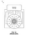
- FIG. 1Aillustrates a conventional circular slider interface 105 having a center mechanical button 110 .
- the illustrated circular slider interface 105includes eight radial capacitance sensors 115 encircling mechanical button 110 and a processing device 120 .
- Processing device 120monitors capacitive changes in each of capacitance sensors 115 to register user interactions with circular slider interface 105 .
- Circular slidersmay be used to convey absolute positional information of a conductive object, such as to emulate a mouse in controlling cursor position on a display, or to emulate a scrolling function of the mouse. Circular sliders may also be used to actuate one or more functions associated with sensing elements of a sensing device.
- FIG. 1Billustrates a conventional linear slider interface 130 .
- Linear slider interface 130includes a surface area on which a conductive object may be used to position a cursor in the x-axis (or alternatively in the y-axis).
- Linear slider interface 130may include a one-dimensional array of capacitance sensors 135 .
- the individual capacitance sensors 135will sense capacitive variations that are translated into an absolute or relative user interaction position.
- the capacitance variationmay be sent as a signal to a coupled processing device (not illustrated) for analysis. For example, by detecting the capacitance variation of each sensor element, the position of the changing capacitance can be pinpointed. In other words, it can be determined which sensor element has detected the presence of the conductive object, and the motion and/or the position of the conductive object over multiple sensor elements can also be determined.
- FIG. 1Cillustrates a conventional touch pad interface 140 .
- Touch pad interface 140is often used in notebook computers to emulate the function of a personal computer (“PC”) mouse.
- a touch pad interfaceis typically embedded into a PC notebook for built-in portability.
- Touch pad interface 140can replicate mouse x/y movement by using two defined axes which contain a collection of sensor elements that detect the position of a conductive object, e.g., a finger.
- Mouse right/left button clickscan be replicated by two mechanical buttons, located in the vicinity of touch pad interface 140 , or by tapping commands on touch pad interface 140 itself.
- Touch pad interface 140provides a user interface device for performing such functions as positioning a cursor or selecting an item on a display.
- Touch pad interface 140may include multi-dimensional sensor arrays for detecting movement in multiple axes.
- touch pad interface 140may be implemented as a two-dimensional array of linear sliders.
- FIG. 1Aillustrates a conventional circular slider interface having a center mechanical button.
- FIG. 1Billustrates a conventional linear slider interface
- FIG. 1Cillustrates a conventional touch pad interface
- FIG. 2illustrates a user finger interacting with a capacitance sensor, in accordance with an embodiment of the invention
- FIG. 3illustrates a user device having both a mechanical button user interface (“I/F”) and a capacitive (“CAP”) sense user I/F, in accordance with an embodiment of the invention.
- I/Fmechanical button user interface
- CAPcapacitive
- FIG. 4is a flow chart illustrating a process to trigger an activation of a capacitance sensor, in accordance with an embodiment of the invention.
- FIG. 5is a table illustrating assignment of different sensitivities to capacitance sensors within a CAP sense user I/F to prioritize the capacitance sensors, in accordance with an embodiment of the invention.
- FIG. 6is a flow chart illustrating a process for masking (or rejecting) concurrent activations of multiple capacitance sensors, in accordance with an embodiment of the invention.
- FIG. 7Ais a diagram illustrating a user device configured to operate in a portrait mode when the user device is operated in a portrait orientation, in accordance with an embodiment of the invention.
- FIG. 7Bis a diagram illustrating a user device configured to operate in a landscape mode when the user device is operated in a landscape orientation, in accordance with an embodiment of the invention.
- FIG. 7Cis a diagram illustrating a user device configured to operate in a dual-mode irrespective of an orientation of the user device, in accordance with an embodiment of the invention.
- FIG. 8is a functional block diagram illustrating a demonstrative processing system for implementing a CAP sense user I/F, in accordance with an embodiment of the invention.
- FIG. 9is a circuit diagram illustrating a demonstrative capacitance sensor circuit, in accordance with an embodiment of the invention.
- Embodiments of a method, apparatus, and system for implementing a capacitive sense user interfaceare described herein.
- numerous specific detailsare set forth to provide a thorough understanding of the embodiments.
- One skilled in the relevant artwill recognize, however, that the techniques described herein can be practiced without one or more of the specific details, or with other methods, components, materials, etc.
- well-known structures, materials, or operationsare not shown or described in detail to avoid obscuring certain aspects.
- FIG. 2illustrates a user finger 205 interacting with a capacitance sensor 200 , in accordance with an embodiment of the invention.
- a conductive objectsuch as user finger 205
- a measurable capacitance change ⁇ Coccurs at capacitance sensor 200 .
- a user interaction with capacitance sensor 200is not limited to a finger.
- Other conductive objectsmay be used to interact with capacitance sensor 200 , including a stylus, a pen, or any other conductive object.
- an activation of capacitance sensor 200can be determined (or triggered) and accepted (or registered) as a user activation in software.
- accepting (or registering) an activation of capacitance sensor 200means acknowledging in software that a user likely intended for an appropriate action or function that is associated with capacitance sensor 200 to be executed.
- rejecting (or masking) an activation of capacitance sensor 200is an acknowledgment by software that the activation of capacitance sensor 200 is ignored as an unintended or erroneous activation.
- a variety of capacitance (“CAP”) sense user interfacesmay be implemented by grouping a plurality of capacitance sensors 200 into an array of capacitance sensors, such as a circular slider array, a linear slider array, a touch pad array, a keypad, or the like.
- an array of capacitance sensors 200may be used to implement user interfaces of a variety of products/devices including: door switches, white goods (e.g., kitchen appliances), laptop computers, desktop computers, personal digital assistants (“PDAs”), portable music players (e.g., MP3 players), wireless telephones, cellular telephones, radios, or the like.
- Capacitance sensor arraysmay also be used to implement position sensors. While embodiments herein are described in relation to a keypad, it should be understood by a person of ordinary skill in the art having the benefit of the instant disclosure that embodiments of the invention may be utilized with alternative user interfaces, such as those described above.
- FIG. 3illustrates a user device 300 including a CAP sense user interface (“I/F”) that provides a more productive and pleasurable user experience over conventional CAP sense user interfaces, in accordance with an embodiment of the invention.
- the illustrated embodiment of user device 300includes a device enclosure 305 , screen 310 , mechanical button user I/F 315 , and CAP sense user I/F 320 .
- CAP sense user I/F 320includes an array of nine capacitance sensors 325 A- 325 C (collectively 325 ) including: four capacitance sensors 325 A assigned to implement pointer or arrow functions, four capacitance sensors 325 B located at corners of CAP sense user I/F 320 , and one capacitance sensor 325 C assigned to implement select or enter functions.
- FIG. 3illustrates a user device 300 including a CAP sense user interface (“I/F”) that provides a more productive and pleasurable user experience over conventional CAP sense user interfaces, in accordance with an embodiment of the invention.
- FIG. 3illustrates an embodiment of CAP sense user I/F 320 that includes an array of nine capacitance sensors 325 , it should be appreciated that other embodiments may include more or less capacitance sensors 325 , may include capacitance sensors 325 that perform functions different from those described in this specification, and may include capacitance sensors 325 placed at different locations and orientations.
- CAP sense user I/F 320may not provide tactile feedback to a user who intends to activate only one of the capacitance sensors 325 because a user does not have to touch CAP sense user I/F 320 for measurable capacitance changes to occur on capacitance sensors 325 . Therefore, in order to provide a pleasurable and productive user experience, one or more mechanisms may be used to determine which capacitance sensor 325 a user likely intended to activate when the user concurrently activates multiple capacitance sensors 325 .
- one mechanism used to determine which capacitance sensor 325 a user likely intended to activate when the user concurrently activates multiple capacitance sensors 325is to consider one or more conditions before triggering an activation of a capacitance sensor 325 .
- FIG. 4is a flow chart illustrating process 400 that includes one or more conditions that may be considered before triggering an activation of a capacitance sensor 325 , in accordance with an embodiment of the invention.
- Process 400 and the processes explained belowmay be used in connection with CAP sense user I/F 320 or other CAP sense user interfaces and are described in terms of computer software and hardware.
- the process blocks describedmay constitute machine-executable instructions embodied within a machine (e.g., computer) readable medium, which when executed by a machine will cause the machine to perform the operations described. Additionally, the processes may be embodied within hardware, such as an application specific integrated circuit (“ASIC”) or the like.
- ASICapplication specific integrated circuit
- a userinteracts with CAP sense user I/F 320 by bringing a conductive object (e.g., user's finger) proximate to CAP sense user I/F 320 .
- a conductive objecte.g., user's finger
- logicdetermines whether a threshold capacitance change condition ⁇ C TH (or threshold deviation from a baseline capacitance value) occurred on a capacitance sensor 325 . If the threshold capacitance change condition ⁇ C TH has occurred, process 400 continues to a decision block 415 , else process 400 returns to process block 405 .
- decision block 415logic determines whether a threshold capacitance change duration condition T ⁇ C TH has occurred on capacitance sensor 325 . In other words, the logic determines whether the threshold capacitance change condition ⁇ C TH has occurred for at least the amount of time set by the threshold capacitance change duration condition T ⁇ C TH . If the threshold capacitance change duration condition T ⁇ C TH has occurred, process 400 continues to a process block 420 . In process block 420 , an activation of the capacitance sensor 325 is triggered. However, it should be appreciated that if multiple concurrent activations have occurred, then whether a particular activation is accepted or rejected may be determined as described below.
- process 400returns to decision block 410 .
- a capacitance sensor's threshold sensitivity that triggers its activationcan be manipulated.
- a different threshold sensitivitycan be assigned to different capacitance sensors 325 , so that the activation of some capacitance sensors 325 may be preferred over the activation of other capacitance sensors 325 .
- FIG. 5is a table illustrating assignment of different sensitivities to different capacitance sensors 325 to prioritize capacitance sensors 325 based on their assigned function or their physical location within CAP sense user I/F 320 , in accordance with an embodiment of the invention.
- capacitance sensors 325 assigned to implement pointer or arrow functionsare more sensitive than capacitance sensors 325 located at the corners of CAP sense user I/F 320 .
- capacitance sensors 325 located at corners of CAP sense user I/F 320are more sensitive than capacitance sensors 325 assigned to implement select or enter functions.
- FIG. 7Aillustrates user device 300 configured to operate in a portrait mode when user device 300 is operated in a portrait orientation.
- FIG. 7Billustrates user device 300 configured to operate in a landscape mode when user device 300 is operated in a landscape orientation.
- FIG. 7Cillustrates user device 300 configured to operate in a dual-mode, irrespective of its physical orientation.
- a capacitance sensor activation 420occurs. If a user places his/her finger proximate to more than one capacitance sensor of CAP sense user I/F 320 , he/she may concurrently activate multiple capacitance sensors 325 . If concurrent activations of multiple capacitance sensors 325 have occurred (decision block 610 ), then process 600 continues to a decision block 615 . If a single capacitance sensor activation has occurred, then process 600 continues to a process block 635 , in which the single capacitance sensor activation is accepted as a user activation.
- the user mode of user device 300is determined.
- user device 300can be configured to operate in either a portrait mode, a landscape mode, or a dual-mode, in accordance with an embodiment of the invention. While embodiments herein are described in relation to the portrait mode, the landscape mode, or the dual-mode configuration of user device 300 , it should be understood by a person of ordinary skill in the art having the benefit of the instant disclosure that embodiments of the invention may be utilized with some or all of the modes herein described, including alternative user modes referenced to alternative user configurations.
- FIG. 7Ais a diagram illustrating user device 300 configured to operate in the portrait mode when user device 300 is operated in a portrait orientation, in accordance with an embodiment of the invention.
- the illustrated embodiment of user device 300is operated in the portrait orientation when its y-axis is vertically oriented. However, it should be appreciated that other embodiments may be operated in the portrait mode when the y-axis of user device 300 is operated in orientations different from those described in this specification.
- FIG. 7Afurther illustrates a user's finger concurrently activating multiple capacitance sensors (i.e., two capacitance sensors 325 A and two capacitance sensors 325 B) within CAP sense user I/F 320 . Although the user's finger is proximate to capacitance sensor 325 C, capacitance sensor 325 C is not activated because one or both of the conditions for activation described by process 400 is not satisfied.
- process 600continues from decision block 615 to a process block 620 .
- process block 620concurrent activations of capacitance sensors physically located below a top-most capacitance sensor activation are rejected.
- “below”is not limited to meaning “directly below” or “directly vertically below.” Rather, the term “below” is a relative term that means below, along the y-axis of user device 300 , as depicted by a dashed line illustrated in FIG. 7A . As illustrated in FIG.
- FIG. 7Billustrates user device 300 configured to operate in the landscape mode when user device 300 is operated in a landscape orientation, in accordance with an embodiment of the invention.
- the illustrated embodiment of user device 300is operated in the landscape orientation when its y-axis is horizontally oriented.
- FIG. 7Bfurther illustrates a user's finger concurrently activating multiple capacitance sensors (i.e., one capacitance sensor 325 A and two capacitance sensors 325 B) within CAP sense user I/F 320 .
- process 600continues from decision block 615 to a process block 625 .
- process block 625concurrent activations of capacitance sensors physically located below a top-most capacitance sensor activation are rejected.
- “below”is not limited to meaning “directly below” or “directly vertically below.” Rather, the term “below” is a relative term that means below, along the x-axis of user device 300 , as depicted by a dashed line illustrated in FIG. 7B . As illustrated in FIG.
- FIG. 7Cis a diagram illustrating user device 300 configured to operate in the dual-mode, in accordance with an embodiment of the invention. Dual-mode applies a single set of masking rules, irrespective of the physical orientation of user device 300 . FIG. 7C further illustrates a user's finger concurrently activating multiple capacitance sensors (i.e., two capacitance sensors 325 A, one capacitance sensor 325 B, and one capacitance sensor 325 C) within CAP sense user I/F 320 . If user device 300 is configured to operate in the dual-mode, process 600 continues from decision block 615 to a process block 630 .
- multiple capacitance sensorsi.e., two capacitance sensors 325 A, one capacitance sensor 325 B, and one capacitance sensor 325 C
- process block 630concurrent activations of capacitance sensors physically located below and/or laterally right of a top-left-most capacitance sensor activation are rejected.
- “below”is not limited to meaning “directly below” or “directly vertically below.” Rather, the term “below” is a relative term that means below an axis 705 .
- “laterally right”is not limited to meaning “directly right” or “directly horizontally right.” Rather, the phrase “laterally right” is a relative phrase that means right of an axis 710 . While embodiments herein are described in relation to the axes 705 and 710 shown in FIG. 7C , it should be understood by a person of ordinary skill in the art having the benefit of the instant disclosure that embodiments of the invention may be utilized with alternative axes at alternative locations of CAP sense user I/F 320 .
- three activated capacitance sensorsi.e., two activated capacitance sensors 325 A and one activated capacitance sensor 325 B) physically located below and/or laterally right of top-left-most activated capacitance sensor 325 (sensor 325 C labeled “SEL” on CAP sense user I/F 320 ) are rejected.
- Process 600then continues to process block 635 .
- the top-left-most activated capacitance sensor 325is accepted as a user activation.
- the masking rules set forth by the portrait, landscape, and dual-mode configurationsare pre-empted by implementing a prioritization between the top-most activated capacitance sensors physically located laterally left or right of each other.
- capacitance sensor 325 C labeled “SEL” and capacitance sensor 325 A labeled “ ⁇ ”may be assigned different priority levels via differing sensitivities.
- the prioritization ruleswill preempt the masking rules. For example, referring to FIG.
- capacitance sensor 325 C labeled “SEL”is registered while capacitance sensor 325 A labeled “ ⁇ ” is masked.
- capacitance sensor 325 A labeled “ ⁇ ”is assigned a higher priority over capacitance sensor 325 C labeled “SEL”
- capacitance sensor 325 C labeled “SEL”is masked and capacitance sensor 325 A labeled “ ⁇ ” is registered.
- the masking rules illustrated in FIG. 6are preempted by prioritizing the top-most activated capacitance sensors among the concurrently activated capacitance sensors.
- FIG. 8is a functional block diagram illustrating a demonstrative system 800 for implementing a capacitance sense user interface, in accordance with an embodiment of the invention.
- System 800includes a processing device 810 , a capacitive sense pad 820 , a capacitive sense linear slider 830 , a capacitive sense circular slider 840 , a capacitive sense keypad 850 , a host processor 860 , an embedded controller 870 , and non-capacitance sensor elements 880 .
- Processing device 810may include analog and/or digital general purpose input/output (“GPIO”) ports 807 .
- GPIO ports 807may be programmable.
- GPIO ports 807may be coupled to Programmable Interconnect and Logic, which acts as an interconnect between GPIO ports 807 and a digital block array of processing device 810 (not illustrated).
- the digital block arraymay be configured to implement a variety of digital logic circuits (e.g., digital filters, digital control systems, etc.) using, in one embodiment, configurable user modules (“UMs”).
- the digital block arraymay be coupled to a system bus.
- Processing device 810may also include memory, such as random access memory (“RAM”) 805 and program flash (“FLASH”) 804 .
- RAM 805may be static RAM (“SRAM”), and FLASH 804 may be a non-volatile storage, which may be used to store firmware (e.g., control algorithms executable by processing core 802 to implement operations described herein, such as the aforementioned processes).
- Processing device 810may also include a memory controller unit (“MCU”) 803 coupled to memory and the processing core 802 .
- MCUmemory controller unit
- Processing device 810may also include an analog block array (not illustrated).
- the analog block arrayis also coupled to the system bus.
- the analog block arraymay be configured to implement a variety of analog circuits (e.g., analog-to-digital converters, analog filters, etc.) using, in one embodiment, configurable UMs.
- the analog block arraymay also be coupled to GPIO ports 807 .
- capacitance sensor circuit 801may be integrated into processing device 810 .
- Capacitance sensor circuit 801may include analog input/output (“I/O”) for coupling to an external component, such as capacitive sense pad 820 , capacitive sense linear slider 830 , capacitive sense circular slider 840 , capacitive sense keypad 850 , and/or other devices.
- I/Oanalog input/output
- Capacitance sensor circuit 801is described in more detail below.
- Processing device 810may include internal oscillator/clocks 806 and communication (“COM”) block 808 .
- the oscillator/clocks 806 blockprovides clock signals to one or more of the components of processing device 810 .
- COM block 808may be used to communicate with an external component, such as a host processor 860 , via host I/F 861 .
- processing device 810may also be coupled to embedded controller 870 to communicate with the external components, such as host processor 860 . Interfacing to host processor 860 can be through various methods.
- interfacing with host processor 860may be done using a standard Personal System/2 (“PS/2”) interface to connect to embedded controller 870 , which in turn sends data to host processor 860 via a low pin count interface. In some instances, it may be beneficial for processing device 810 to do both touch-sensor pad and keyboard control operations, thereby freeing up the embedded controller 870 for other functions.
- interfacingmay be done using a universal serial bus (“USB”) interface directly coupled to host processor 860 via host I/F 861 .
- processing device 810may communicate to external components, such as host processor 860 using industry standard interfaces, such as USB, PS/2, inter-integrated circuit (“I2C”) bus, or Serial Peripheral Interface (“SPI”) bus.
- Host processor 860 and/or embedded controller 870may be coupled to processing device 810 with a ribbon or flex cable from an assembly, which houses a sensing device and processing device 810 .
- processing device 810is configured to communicate with embedded controller 870 or host processor 860 to send and/or receive data.
- the datamay be commands or signals.
- system 800may operate in both standard-mouse compatible and enhanced modes.
- the standard-mouse compatible modeutilizes the Human Interface Device (“HID”) class drivers already built into the Operating System (“OS”) software of host processor 860 .
- HIDHuman Interface Device
- OSOperating System
- These driversenable processing device 810 and a sensing device to operate as a standard cursor control user interface device, such as a two-button PS/2 mouse.
- the enhanced modemay enable additional features such as scrolling, reporting absolute position, or disabling the sensing device (e.g., when a mouse is plugged into the notebook).
- processing device 810may be configured to communicate with embedded controller 870 or host processor 860 , using non-OS drivers, such as dedicated touch-sensor pad drivers or other drivers known by those of ordinary skill in the art.
- Processing device 810may reside on a common carrier substrate such as an integrated circuit (“IC”) die substrate, a multi-chip module substrate, or the like. Alternatively, the components of processing device 810 may be one or more separate integrated circuits and/or discrete components. In one embodiment, processing device 810 may be a Programmable System on a Chip (“PSoCTM”) processing device, manufactured by Cypress Semiconductor Corporation, San Jose, Calif. Alternatively, processing device 810 may be one or more other processing devices known by those of ordinary skill in the art, such as a microprocessor or central processing unit, a controller, a special-purpose processor, a digital signal processor (“DSP”), a field programmable gate array (“FPGA”), an application specific integrated circuit (“ASIC”), or the like. In an alternative embodiment, for example, processing device 810 may be a network processor having multiple processors including a core unit and multiple microengines. Additionally, processing device 810 may include any combination of general-purpose processing device(s) and special-purpose processing device(s).
- POP
- Capacitance sensor circuit 801may be integrated into an IC of processing device 810 , or alternatively, in a separate IC. Descriptions of capacitance sensor circuit 801 may be generated and compiled for incorporation into other integrated circuits. For example, behavioral level code describing capacitance sensor circuit 801 , or portions thereof, may be generated using a hardware descriptive language, such as Very High Speed Integrated Circuits Hardware Description Language (“VHDL”) or Verilog, and stored to a machine-accessible medium (e.g., compact disk-read only memory (“CD-ROM”), hard disk, floppy disk, etc.). Furthermore, the behavioral level code can be compiled into register transfer level (“RTL”) code, a netlist, or even a circuit layout and stored to a machine-accessible medium. The behavioral level code, RTL code, netlist, and circuit layout all represent various levels of abstraction to describe capacitance sensor circuit 801 .
- VHDLVery High Speed Integrated Circuits Hardware Description Language
- VerilogVerilog
- system 800may be used in a notebook computer.
- system 800may be used in other applications, such as a mobile handset, personal data assistant (“PDA”), keyboard, television, remote control, monitor, handheld multi-media device, handheld video player, handheld gaming device, or control panel.
- PDApersonal data assistant
- capacitance sensor circuit 801may be a capacitive switch relaxation oscillator (“CSR”).
- the CSRmay have an array of capacitive sensors using a current-programmable relaxation oscillator, an analog multiplexer, digital counting functions, and high-level software routines to compensate for environmental and physical capacitance sensor variations.
- the CSRmay include physical, electrical, and/or software components.
- the physical componentmay include a physical array of capacitance sensors, typically a pattern constructed on a printed circuit board (“PCB”) with an insulating cover, a flexible membrane, or a transparent overlay.
- the electrical componentmay include an oscillator or other means to convert a changed capacitance into a measured signal.
- the electrical componentmay also include a counter or timer to measure the oscillator output.
- the software componentmay include detection, compensation, and decision software algorithms to convert the count value into a capacitive sensor detection decision.
- the current versus voltage phase shift measurementmay include driving the capacitance through a fixed-value resistor to yield voltage and current waveforms that are out of phase by a predictable amount.
- the drive frequencycan be adjusted to keep the phase measurement in a readily measured range.
- the resistor-capacitor charge timingmay include charging the capacitor through a fixed resistor and measuring timing on the voltage ramp. Small capacitor values may require very large resistors for reasonable timing.
- the capacitive bridge dividermay include driving the capacitor under test through a fixed reference capacitor. The reference capacitor and the capacitor under test form a voltage divider.
- the voltage signalis recovered with a synchronous demodulator, which may be done in processing device 810 .
- the charge transfermay be conceptually similar to an R-C charging circuit.
- C Pis the capacitance being sensed and C SUM is the summing capacitor, into which charge is transferred on successive cycles.
- C SUMis the summing capacitor, into which charge is transferred on successive cycles.
- the voltage on C SUMis reset.
- the voltage on C SUMincreases exponentially (and only slightly) with each clock cycle. The time for this voltage to reach a specific threshold is measured with a counter.
- FIG. 9illustrates one embodiment of capacitance sensor circuit 801 implemented with a relaxation oscillator circuit 900 .
- the illustrated embodiment of capacitance sensor circuit 801includes relaxation oscillator circuit 900 , an analog multiplexer (“MUX”) bus 901 , a CAP sensor array 910 , and a digital counter 920 .
- CAP sensor array 910may represent any form of capacitance sensors, such as a circular slider array, linear slider array, touch pad array, keypad array, or the like.
- Relaxation oscillator 900is formed by the capacitance to be measured on capacitance sensors 951 , a charging current source 952 , a comparator 953 , and a reset switch 954 .
- Capacitance sensors 951are representative of the capacitance measured on a sensor element of a CAP sensor array 910 .
- the relaxation oscillatoris coupled to drive a charging current Ic in a single direction onto a device under test (“DUT”) capacitor (e.g., any of the capacitance sensors 951 ).
- DUTdevice under test
- Equation (1)describes the relation between current, capacitance, voltage, and time for a charging capacitor.
- CdVI c dt (1)
- the relaxation oscillatorbegins by charging a capacitance sensor 951 , at a fixed current Ic, from a ground potential (or zero voltage) until the voltage across the capacitance sensor 951 reaches a reference voltage or threshold voltage V TH 955 .
- the relaxation oscillatorallows the accumulated charge at node 970 to discharge (i.e., the relaxation oscillator allows the capacitance sensor 951 to “relax” back to the ground potential) and then the process repeats itself.
- the output of comparator 953asserts a relaxation oscillator clock signal (“F OUT ”) 956 (i.e., F OUT goes high), which enables the reset switch 954 . This resets the voltage on the capacitor at node 970 to ground and the charge cycle starts again.
- the frequency of F OUT 956f RO , is dependent upon capacitance C of the capacitance sensor 951 and charging current Ic.
- the trip time of the comparator 953 and reset switch 954add a fixed delay.
- the output of the comparator 953is synchronized with a reference system clock (“REF CLK”) to guarantee that the comparator reset time is long enough to completely reset the charging voltage on capacitance sensor 951 .
- REF CLKreference system clock
- a frequency comparatormay be coupled to receive relaxation oscillator clock signal F OUT 956 and REF CLK, compare their frequencies f RO and f REF , respectively, and output a signal indicative of the difference ⁇ f between these frequencies. By monitoring ⁇ f, one can determine whether the capacitance of the capacitance sensor 951 has changed.
- the relaxation oscillator 950may be built using a programmable timer (e.g., 555 timer) to implement the comparator 953 and reset switch 954 .
- the relaxation oscillator 900may be built using other circuits.
- Sensor array 910includes a plurality of capacitance sensors 951 ( 1 )- 951 (N), where N is a positive integer value that represents the number of capacitive sensors within any array of capacitance sensors of capacitive sense pad 820 , capacitive sense linear slider 830 , capacitive sense circular slider 840 , or capacitive sense keypad 850 .
- Relaxation oscillator 900further includes a selection circuit 930 .
- Selection circuit 930is coupled to the plurality of capacitance sensors 951 ( 1 )- 951 (N), the reset switch 954 , the current source 952 , and the comparator 953 .
- Selection circuit 930may be used to allow the relaxation oscillator 900 to measure capacitance on multiple sensor elements (e.g., rows or columns). Selection circuit 930 may be configured to sequentially select a capacitance sensor from the plurality of capacitance sensors 951 ( 1 )- 951 (N) to provide charge current and to measure the capacitance of a capacitance sensor 951 .
- selection circuit 930is a multiplexer array of relaxation oscillator 900 .
- selection circuit 930may be other circuitry outside relaxation oscillator 900 , or even outside capacitance sensor circuit 801 , used to select the capacitance sensor 951 to be measured.
- Capacitance sensor circuit 801may include one relaxation oscillator and digital counter for the plurality of capacitance sensors 951 ( 1 )- 951 (N) of CAP sensor array 910 .
- capacitance sensor circuit 801may include multiple relaxation oscillators and digital counters to measure capacitance of the plurality of capacitance sensors 951 ( 1 )- 951 (N) of CAP sensor array 910 .
- the multiplexer array of relaxation oscillator 900may also be used to ground the sensor elements that are not being measured. This may be done in conjunction with a dedicated pin in GPIO port 807 .
- capacitance sensor circuit 801may be configured to simultaneously scan the sensor elements, as opposed to being configured to sequentially scan the sensor elements as described above.
- the sensing devicemay include a sensor array having a plurality of rows and columns. The rows may be scanned simultaneously and the columns may be scanned simultaneously.
- the voltages on all of the rows of CAP sensor array 910are simultaneously moved, while the voltages of the columns are held at a constant voltage, with the complete set of sampled points simultaneously giving a profile of the conductive object in a first dimension.
- the voltages on all of the rowsare held at a constant voltage, while the voltages on all the rows are simultaneously moved, to obtain a complete set of sampled points simultaneously giving a profile of the conductive object in a second dimension.
- the voltages on all of the rows of CAP sensor array 910are simultaneously moved in a positive direction, while the voltages of the columns are moved in a negative direction.
- the voltages on all of the rows of CAP sensor array 910are simultaneously moved in a negative direction, while the voltages of the columns are moved in a positive direction.
- digital counter 920is coupled to the output of relaxation oscillator 900 (i.e., F OUT 956 ).
- Digital counter 920is configured to count at least one of a frequency or a period of F OUT 956 .
- F OUT 956When a finger or conductive object is placed proximate to a capacitance sensor 951 , the capacitance increases so the relaxation oscillator output signal F OUT 956 decreases.
- digital counter 920may include two multiplexers 923 and 924 . Multiplexers 923 and 924 are configured to select the inputs for a pulse width modulator (“PWM”) 921 and a timer 922 for the frequency and period measurement methods.
- PWMpulse width modulator
- multiplexers 923 and 924are not included in the digital counter (e.g., digital counter 920 may be configured in one, or the other, measurement method).
- the relaxation oscillator output signal F OUT 956is counted for a fixed period of time (e.g., gate time). Timer 922 is read to obtain the number of counts during the gate time. This method works well at low frequencies where the oscillator reset time is small compared to the oscillator period.
- PWM 921is clocked for a fixed period by a derivative of the system clock 925 (e.g., VC3 926 , which is a divider from system clock 925 ). The output of PWM 921 enables timer 922 (e.g., 16-bit timer), the relaxation oscillator output signal F OUT 956 clocks timer 922 , and timer 922 is reset at the start of the sequence. The count value is read out at the end of the gate period.
- relaxation oscillator output signal F OUT 956drives the clock input of PWM 921 .
- the output of PWM 921gates (enables) timer 922 (e.g., 16-bit timer), which is clocked by system clock 925 (e.g., 24 MHz).
- timer 922e.g. 16-bit timer
- system clock 925e.g. 24 MHz
- multiple periods of the oscillatorare counted with PWM 921 .
- the output of PWM 921is asserted (e.g., goes high) the count starts by releasing a capture control signal.
- the capture control signalis asserted (e.g., goes high), stopping the count and setting a PWM interrupt.
- the timer 922 valueis read during this interrupt.
- Relaxation oscillator 900is indexed to the next capacitive sensor (e.g., capacitor 951 ( 2 )) to be measured and the count sequence is started again.
- the timer 922 count time and the detection time required for capacitance sensor circuit 801are determined by sensitivity requirements. Small changes in capacitance on capacitance sensor 951 result in small changes in frequency. In order to find these small changes, it may be necessary to count for a considerable time.
- the capacitance sensors 951 ( 1 )-(N)are scanned and the count values for each capacitance sensor are stored as a baseline array (Cp).
- the presence of a finger proximate to a capacitance sensor 951is determined by the difference in counts between the count value stored in the baseline array (Cp) and the count value acquired during the capacitive sensor's activation, referred to here as ⁇ n.
- the sensitivity of a single capacitive sensorsis approximately:
- ⁇ ⁇ ⁇ n nCf Cp ( 4 )
- the value of ⁇ nshould be large enough for reasonable resolution and clear indication of a capacitive sensor activation.
- multiple CAP sensor elementsmay be sequentially scanned by providing current to and measuring the capacitance from the CAP sense elements, as previously described. In other words, while one CAP sensor element is being measured, the remaining sensor elements are grounded using GPIO port 807 .
- This drive and multiplex arrangementbypasses the existing GPIO to connect the selected pin to an internal analog MUX bus.
- the capacitor charge currente.g., current provided by current source 952
- reset switch 953are connected to the analog MUX bus. This may limit the pin-count requirement to simply the number of capacitive sensors 951 ( 1 )- 951 (N) to be addressed. In one exemplary embodiment, no external resistors or capacitors are required inside or outside the processing device 910 to enable operation.
- the capacitor charging current for the relaxation oscillator 900is generated in a register programmable current output digital-to-analog converter (“IDAC”). Accordingly, the current source 952 is an IDAC.
- the output current of current source 952may be set by an 8-bit value provided by processing device 810 , such as from processing core 802 .
- the 8-bit valuemay be stored in a register or in memory.
- the oscillator-reset timemay add to the oscillator period (especially at higher frequencies) and the magnitude of the IDAC output current may vary with operating frequency. Accordingly, the optimum oscillation frequency and operating current for a particular switch array may be determined to some degree by experimentation.
Landscapes
- Engineering & Computer Science (AREA)
- Theoretical Computer Science (AREA)
- General Engineering & Computer Science (AREA)
- Human Computer Interaction (AREA)
- Physics & Mathematics (AREA)
- General Physics & Mathematics (AREA)
- Computer Hardware Design (AREA)
- User Interface Of Digital Computer (AREA)
Abstract
Description
CdV=Icdt (1)
ΔC∝1/Δf, where (2)
Δf=fRO−fREF. (3)
The value of Δn should be large enough for reasonable resolution and clear indication of a capacitive sensor activation.
Claims (20)
Priority Applications (1)
| Application Number | Priority Date | Filing Date | Title |
|---|---|---|---|
| US11/509,513US9766738B1 (en) | 2006-08-23 | 2006-08-23 | Position and usage based prioritization for capacitance sense interface |
Applications Claiming Priority (1)
| Application Number | Priority Date | Filing Date | Title |
|---|---|---|---|
| US11/509,513US9766738B1 (en) | 2006-08-23 | 2006-08-23 | Position and usage based prioritization for capacitance sense interface |
Publications (1)
| Publication Number | Publication Date |
|---|---|
| US9766738B1true US9766738B1 (en) | 2017-09-19 |
Family
ID=59828517
Family Applications (1)
| Application Number | Title | Priority Date | Filing Date |
|---|---|---|---|
| US11/509,513Active2032-09-26US9766738B1 (en) | 2006-08-23 | 2006-08-23 | Position and usage based prioritization for capacitance sense interface |
Country Status (1)
| Country | Link |
|---|---|
| US (1) | US9766738B1 (en) |
Cited By (1)
| Publication number | Priority date | Publication date | Assignee | Title |
|---|---|---|---|---|
| US20220100309A1 (en)* | 2018-12-26 | 2022-03-31 | Microchip Technology Incorporated | Digital-to-analog controller-referenced touch sensing system, and related systems, methods, and devices |
Citations (165)
| Publication number | Priority date | Publication date | Assignee | Title |
|---|---|---|---|---|
| US3696908A (en) | 1970-11-09 | 1972-10-10 | Sperry Rand Corp | Capacitive key |
| US3974332A (en) | 1974-12-03 | 1976-08-10 | Pentel Kabushiki Kaisha | Tablet for use in a coordinate digitizer |
| US4283713A (en) | 1979-01-15 | 1981-08-11 | Tektronix, Inc. | Waveform acquisition circuit |
| US4305135A (en)* | 1979-07-30 | 1981-12-08 | International Business Machines Corp. | Program controlled capacitive keyboard variable threshold sensing system |
| US4438404A (en) | 1982-01-04 | 1984-03-20 | Tektronix, Inc. | Signal sampling system |
| US4475151A (en) | 1982-11-04 | 1984-10-02 | Harald Philipp | Switching amplifier circuit |
| US4497575A (en) | 1982-11-01 | 1985-02-05 | Tektronix, Inc. | Optical fiber test instrument calibrator |
| US4543564A (en) | 1981-04-03 | 1985-09-24 | Commissariat A L'energie Atomique | Interference suppression apparatus for a capacitive keyboard |
| US4736097A (en) | 1987-02-02 | 1988-04-05 | Harald Philipp | Optical motion sensor |
| US4773024A (en) | 1986-06-03 | 1988-09-20 | Synaptics, Inc. | Brain emulation circuit with reduced confusion |
| US4876534A (en) | 1988-02-05 | 1989-10-24 | Synaptics Incorporated | Scanning method and apparatus for current signals having large dynamic range |
| US4879461A (en) | 1988-04-25 | 1989-11-07 | Harald Philipp | Energy field sensor using summing means |
| US4935702A (en) | 1988-12-09 | 1990-06-19 | Synaptics, Inc. | Subthreshold CMOS amplifier with offset adaptation |
| US4953928A (en) | 1989-06-09 | 1990-09-04 | Synaptics Inc. | MOS device for long-term learning |
| US4954823A (en) | 1984-04-17 | 1990-09-04 | Binstead Ronald P | Touch keyboard systems |
| US4962342A (en) | 1989-05-04 | 1990-10-09 | Synaptics, Inc. | Dynamic synapse for neural network |
| US5049758A (en) | 1988-12-09 | 1991-09-17 | Synaptics, Incorporated | Adaptable CMOS winner-take all circuit |
| US5055827A (en) | 1990-02-20 | 1991-10-08 | Harald Philipp | Fiber optic security system |
| US5059920A (en) | 1988-12-09 | 1991-10-22 | Synaptics, Incorporated | CMOS amplifier with offset adaptation |
| US5068622A (en) | 1988-12-09 | 1991-11-26 | Synaptics, Incorporated | CMOS amplifier with offset adaptation |
| US5073759A (en) | 1988-12-09 | 1991-12-17 | Synaptics, Incorporated | Adaptable current mirror |
| US5083044A (en) | 1989-03-10 | 1992-01-21 | Synaptics, Incorporated | Synaptic element and array |
| US5095284A (en) | 1990-09-10 | 1992-03-10 | Synaptics, Incorporated | Subthreshold CMOS amplifier with wide input voltage range |
| US5097305A (en) | 1991-02-19 | 1992-03-17 | Synaptics Corporation | Integrating photosensor and imaging system having wide dynamic range |
| US5107149A (en) | 1990-12-18 | 1992-04-21 | Synaptics, Inc. | Linear, continuous-time, two quadrant multiplier |
| US5109261A (en) | 1988-12-09 | 1992-04-28 | Synaptics, Incorporated | CMOS amplifier with offset adaptation |
| US5119038A (en) | 1988-12-09 | 1992-06-02 | Synaptics, Corporation | CMOS current mirror with offset adaptation |
| US5120996A (en) | 1989-03-10 | 1992-06-09 | Synaptics, Incorporated | Synaptic element and array |
| US5122800A (en) | 1989-01-26 | 1992-06-16 | Harald Philipp | Variable successive approximation converter |
| US5126685A (en) | 1990-12-18 | 1992-06-30 | Synaptics, Incorporated | Circuits for linear conversion between voltages and currents |
| US5146106A (en) | 1988-12-09 | 1992-09-08 | Synaptics, Incorporated | CMOS winner-take all circuit with offset adaptation |
| US5160899A (en) | 1988-12-09 | 1992-11-03 | Synaptics, Incorporated | Adaptable MOS current mirror |
| US5165054A (en) | 1990-12-18 | 1992-11-17 | Synaptics, Incorporated | Circuits for linear conversion between currents and voltages |
| US5166562A (en) | 1991-05-09 | 1992-11-24 | Synaptics, Incorporated | Writable analog reference voltage storage device |
| US5204549A (en) | 1992-01-28 | 1993-04-20 | Synaptics, Incorporated | Synaptic element including weight-storage and weight-adjustment circuit |
| US5243554A (en) | 1991-05-09 | 1993-09-07 | Synaptics, Incorporated | Writable analog reference voltage storage device |
| US5248873A (en) | 1991-06-10 | 1993-09-28 | Synaptics, Incorporated | Integrated device for recognition of moving objects |
| US5260592A (en) | 1991-02-19 | 1993-11-09 | Synaptics, Incorporated | Integrating photosensor and imaging system having wide dynamic range with varactors |
| US5270963A (en) | 1988-08-10 | 1993-12-14 | Synaptics, Incorporated | Method and apparatus for performing neighborhood operations on a processing plane |
| US5276407A (en) | 1991-02-19 | 1994-01-04 | Synaptics, Incorporated | Sense amplifier |
| US5289023A (en) | 1991-02-19 | 1994-02-22 | Synaptics, Incorporated | High-density photosensor and contactless imaging array having wide dynamic range |
| US5303329A (en) | 1991-12-10 | 1994-04-12 | Synaptics, Incorporated | Continuous synaptic weight update mechanism |
| US5305017A (en) | 1989-08-16 | 1994-04-19 | Gerpheide George E | Methods and apparatus for data input |
| US5331215A (en) | 1988-12-09 | 1994-07-19 | Synaptics, Incorporated | Electrically adaptable neural network with post-processing circuitry |
| US5336936A (en) | 1992-05-06 | 1994-08-09 | Synaptics, Incorporated | One-transistor adaptable analog storage element and array |
| US5339213A (en) | 1992-11-16 | 1994-08-16 | Cirque Corporation | Portable computer touch pad attachment |
| US5349303A (en) | 1993-07-02 | 1994-09-20 | Cirque Corporation | Electrical charge transfer apparatus |
| US5374787A (en) | 1992-06-08 | 1994-12-20 | Synaptics, Inc. | Object position detector |
| US5381515A (en) | 1988-12-09 | 1995-01-10 | Synaptics, Incorporated | Two layer neural network comprised of neurons with improved input range and input offset |
| US5384467A (en) | 1992-10-16 | 1995-01-24 | AVL Gesellschaft fur Verbrennungskraftmaschinen und Messtechnik m.b.H. Prof.Dr.Dr.h.c. Hans List | Optoelectronic measuring device for monitoring a combustion chamber |
| US5408194A (en) | 1993-06-25 | 1995-04-18 | Synaptics, Incorporated | Adaptive analog minimum/maximum selector and subtractor circuit |
| US5488204A (en) | 1992-06-08 | 1996-01-30 | Synaptics, Incorporated | Paintbrush stylus for capacitive touch sensor pad |
| US5541878A (en) | 1991-05-09 | 1996-07-30 | Synaptics, Incorporated | Writable analog reference voltage storage device |
| US5543590A (en) | 1992-06-08 | 1996-08-06 | Synaptics, Incorporated | Object position detector with edge motion feature |
| US5543591A (en) | 1992-06-08 | 1996-08-06 | Synaptics, Incorporated | Object position detector with edge motion feature and gesture recognition |
| US5543588A (en) | 1992-06-08 | 1996-08-06 | Synaptics, Incorporated | Touch pad driven handheld computing device |
| US5555907A (en) | 1995-06-02 | 1996-09-17 | Philipp; Harald | Divided box for valve controller |
| US5565658A (en) | 1992-07-13 | 1996-10-15 | Cirque Corporation | Capacitance-based proximity with interference rejection apparatus and methods |
| US5566702A (en) | 1994-12-30 | 1996-10-22 | Philipp; Harald | Adaptive faucet controller measuring proximity and motion |
| US5682032A (en) | 1996-02-22 | 1997-10-28 | Philipp; Harald | Capacitively coupled identity verification and escort memory apparatus |
| US5730165A (en) | 1995-12-26 | 1998-03-24 | Philipp; Harald | Time domain capacitive field detector |
| US5734928A (en)* | 1994-04-19 | 1998-03-31 | Sharp Kabushiki Kaisha | System for selecting a key by comparing the key code data of predetermined priority corresponding to key input flag of simultaneously pressed plurality of keys |
| US5757368A (en) | 1995-03-27 | 1998-05-26 | Cirque Corporation | System and method for extending the drag function of a computer pointing device |
| US5767457A (en) | 1995-11-13 | 1998-06-16 | Cirque Corporation | Apparatus and method for audible feedback from input device |
| US5796183A (en) | 1996-01-31 | 1998-08-18 | Nartron Corporation | Capacitive responsive electronic switching circuit |
| US5812698A (en) | 1995-05-12 | 1998-09-22 | Synaptics, Inc. | Handwriting recognition system and method |
| US5844265A (en) | 1996-07-11 | 1998-12-01 | Synaptics, Incorporated | Sense amplifier for high-density imaging array |
| US5854625A (en) | 1996-11-06 | 1998-12-29 | Synaptics, Incorporated | Force sensing touchpad |
| US5861583A (en) | 1992-06-08 | 1999-01-19 | Synaptics, Incorporated | Object position detector |
| US5861875A (en) | 1992-07-13 | 1999-01-19 | Cirque Corporation | Methods and apparatus for data input |
| US5864392A (en) | 1995-12-15 | 1999-01-26 | Avl List Gmbh | Method for optically detecting gas bubbles moving in a coolant |
| US5880411A (en) | 1992-06-08 | 1999-03-09 | Synaptics, Incorporated | Object position detector with edge motion feature and gesture recognition |
| US5889236A (en) | 1992-06-08 | 1999-03-30 | Synaptics Incorporated | Pressure sensitive scrollbar feature |
| US5914708A (en) | 1996-04-04 | 1999-06-22 | Cirque Corporation | Computer input stylus method and apparatus |
| US5914465A (en) | 1992-06-08 | 1999-06-22 | Synaptics, Inc. | Object position detector |
| US5920310A (en) | 1996-11-15 | 1999-07-06 | Synaptics, Incorporated | Electronic device employing a touch sensitive transducer |
| US5926566A (en) | 1996-11-15 | 1999-07-20 | Synaptics, Inc. | Incremental ideographic character input method |
| US5943052A (en) | 1997-08-12 | 1999-08-24 | Synaptics, Incorporated | Method and apparatus for scroll bar control |
| US5942733A (en) | 1992-06-08 | 1999-08-24 | Synaptics, Inc. | Stylus input capacitive touchpad sensor |
| US5969513A (en) | 1998-03-24 | 1999-10-19 | Volterra Semiconductor Corporation | Switched capacitor current source for use in switching regulators |
| US6028271A (en) | 1992-06-08 | 2000-02-22 | Synaptics, Inc. | Object position detector with edge motion feature and gesture recognition |
| US6185450B1 (en) | 1998-01-26 | 2001-02-06 | Physio-Control Manufacturing Corporation | Digital sliding pole fast-restore for an electrocardiograph display |
| US6188228B1 (en) | 1997-11-21 | 2001-02-13 | Harald Philipp | Hammer having integral stud and mains sensor |
| US6188391B1 (en) | 1998-07-09 | 2001-02-13 | Synaptics, Inc. | Two-layer capacitive touchpad and method of making same |
| US6222528B1 (en) | 1997-03-07 | 2001-04-24 | Cirque Corporation | Method and apparatus for data input |
| US6239389B1 (en) | 1992-06-08 | 2001-05-29 | Synaptics, Inc. | Object position detection system and method |
| US6249447B1 (en) | 1999-08-13 | 2001-06-19 | Tyco Electronics Logistics Ag | System and method for determining output current and converter employing the same |
| US6262717B1 (en) | 1998-07-02 | 2001-07-17 | Cirque Corporation | Kiosk touch pad |
| US6280391B1 (en) | 1999-02-08 | 2001-08-28 | Physio-Control Manufacturing Corporation | Method and apparatus for removing baseline wander from an egg signal |
| US6288707B1 (en) | 1996-07-29 | 2001-09-11 | Harald Philipp | Capacitive position sensor |
| US6304014B1 (en) | 1997-10-02 | 2001-10-16 | Synaptics (Uk) Limited | Motor control system |
| US6320184B1 (en) | 1998-07-09 | 2001-11-20 | Avl List Gmbh | Optoelectric measuring device for monitoring combustion processes |
| US6323846B1 (en) | 1998-01-26 | 2001-11-27 | University Of Delaware | Method and apparatus for integrating manual input |
| US6326859B1 (en) | 1999-07-01 | 2001-12-04 | Telefonaktiebolaget Lm Ericsson (Publ) | Oscillator circuit having trimmable capacitor array receiving a reference current |
| US6377009B1 (en) | 1999-09-08 | 2002-04-23 | Harald Philipp | Capacitive closure obstruction sensor |
| US6380929B1 (en) | 1996-09-20 | 2002-04-30 | Synaptics, Incorporated | Pen drawing computer input device |
| US20020063688A1 (en) | 1999-11-04 | 2002-05-30 | Synaptics Incorporated | Capacitive mouse |
| US6430305B1 (en) | 1996-12-20 | 2002-08-06 | Synaptics, Incorporated | Identity verification methods |
| US6441073B1 (en) | 1999-08-17 | 2002-08-27 | Taki Chemical Co., Ltd. | Biological materials |
| US6452514B1 (en) | 1999-01-26 | 2002-09-17 | Harald Philipp | Capacitive sensor and array |
| US6459424B1 (en)* | 1999-08-10 | 2002-10-01 | Hewlett-Packard Company | Touch-sensitive input screen having regional sensitivity and resolution properties |
| US6457355B1 (en) | 1999-08-27 | 2002-10-01 | Harald Philipp | Level sensing |
| US6466036B1 (en) | 1998-11-25 | 2002-10-15 | Harald Philipp | Charge transfer capacitance measurement circuit |
| US6473069B1 (en) | 1995-11-13 | 2002-10-29 | Cirque Corporation | Apparatus and method for tactile feedback from input device |
| US6489899B1 (en) | 1994-05-14 | 2002-12-03 | Synaptics (Uk) Limited | Position detector |
| US20020191029A1 (en) | 2001-05-16 | 2002-12-19 | Synaptics, Inc. | Touch screen with user interface enhancement |
| US6498720B2 (en) | 2001-01-04 | 2002-12-24 | Cirque Corporation | Connector and support system for a touchpad keyboard for use with portable electronic appliances |
| US6499359B1 (en) | 2001-07-09 | 2002-12-31 | Nartron Corporation | Compressible capacitance sensor for determining the presence of an object |
| US20030025679A1 (en) | 1999-06-22 | 2003-02-06 | Cirque Corporation | System for disposing a proximity sensitive touchpad behind a mobile phone keypad |
| US6522128B1 (en) | 1997-10-15 | 2003-02-18 | Synaptics (Uk) Limited | Position sensor having compact arrangement of coils |
| US6523416B2 (en) | 2000-08-31 | 2003-02-25 | Kawasaki Steel Corporation | Method for setting shape and working stress, and working environment of steel member |
| US6535200B2 (en) | 1999-01-25 | 2003-03-18 | Harald Philipp | Capacitive position sensor |
| US6534970B1 (en) | 1998-05-22 | 2003-03-18 | Synaptics (Uk) Limited | Rotary position sensor and transducer for use therein |
| US20030063428A1 (en) | 2001-09-28 | 2003-04-03 | Fujitsu Quantum Devices Limited | Capacitor and method for fabricating the same |
| US20030062889A1 (en) | 1996-12-12 | 2003-04-03 | Synaptics (Uk) Limited | Position detector |
| US20030080755A1 (en) | 2001-10-31 | 2003-05-01 | Kabushiki Kaisha Honda Denshi Giken | Proximity sensor and object detecting device |
| US6570557B1 (en) | 2001-02-10 | 2003-05-27 | Finger Works, Inc. | Multi-touch system and method for emulating modifier keys via fingertip chords |
| US20030160808A1 (en) | 2001-06-07 | 2003-08-28 | Synaptics, Inc. | Method and apparatus for controlling a display of data on a display screen |
| US6624640B2 (en) | 2001-02-07 | 2003-09-23 | Fluke Corporation | Capacitance measurement |
| US20030183884A1 (en) | 2002-03-28 | 2003-10-02 | Fujitsu Quantum Devices Limited | Interdigital capacitor and method for adjusting the same |
| US20030183864A1 (en) | 2002-03-28 | 2003-10-02 | Fujitsu Quantum Devices Limited | Device having interdigital capacitor |
| US20030184315A1 (en) | 2002-04-02 | 2003-10-02 | Dialog Semiconductor Gmbh | Method and circuit for compensating MOSFET capacitance variations in integrated circuits |
| US6639586B2 (en) | 2000-04-11 | 2003-10-28 | Cirque Corporation | Efficient entry of characters from a large character set into a portable information appliance |
| US6642857B1 (en) | 2000-01-19 | 2003-11-04 | Synaptics Incorporated | Capacitive pointing stick |
| US6649924B1 (en) | 1999-09-28 | 2003-11-18 | Avl List Gmbh | Optoelectronic measuring device |
| US6667740B2 (en) | 1998-11-27 | 2003-12-23 | Synaptics (Uk) Limited | Position sensor |
| US6673308B2 (en) | 2000-08-30 | 2004-01-06 | Kabushiki Kaisha Toshiba | Nickel-base single-crystal superalloys, method of manufacturing same and gas turbine high temperature parts made thereof |
| US6677932B1 (en) | 2001-01-28 | 2004-01-13 | Finger Works, Inc. | System and method for recognizing touch typing under limited tactile feedback conditions |
| US6680731B2 (en) | 2000-01-11 | 2004-01-20 | Cirque Corporation | Flexible touchpad sensor grid for conforming to arcuate surfaces |
| US6683462B2 (en) | 2000-11-30 | 2004-01-27 | Agilent Technologies, Inc. | Apparatus for and method of measuring capacitance with high accuracy |
| US6696985B2 (en)* | 2001-04-24 | 2004-02-24 | International Business Machines Corporation | Reformable keyboard with variable key design |
| US6705511B1 (en) | 1997-05-28 | 2004-03-16 | Synaptics (Uk) Limited | Transducer and method of manufacture |
| US6714817B2 (en) | 2001-08-31 | 2004-03-30 | Medtronic Physio-Control Manufacturing Corp. | Hard paddle for an external defibrillator |
| US6730863B1 (en) | 1999-06-22 | 2004-05-04 | Cirque Corporation | Touchpad having increased noise rejection, decreased moisture sensitivity, and improved tracking |
| US6747635B2 (en)* | 2000-12-16 | 2004-06-08 | Kamran Ossia | Multi-mode handheld computer |
| US20040140913A1 (en)* | 2002-12-06 | 2004-07-22 | Harry Engelmann | Method for automatic determination of validity or invalidity of input from a keyboard or a keypad |
| US6788221B1 (en) | 1996-06-28 | 2004-09-07 | Synaptics (Uk) Limited | Signal processing apparatus and method |
| US6798218B2 (en) | 2000-05-23 | 2004-09-28 | Semiconductor Ideas To Market (Itom) B.V. | Circuit for measuring absolute spread in capacitors implemented in planary technology |
| US6809275B1 (en) | 2002-05-13 | 2004-10-26 | Synaptics, Inc. | Rotary and push type input device |
| US20040252109A1 (en) | 2002-04-11 | 2004-12-16 | Synaptics, Inc. | Closed-loop sensor on a solid-state object position detector |
| US20040263864A1 (en) | 2001-10-02 | 2004-12-30 | Fraunhofer-Gesellschaft Zur Forderung Der Angewandten Forschung E.V. | Apparatus and measurement procedure for the fast, quantitative, non-contact topographic investigation of semiconductor wafers and other mirror like surfaces |
| US20050021269A1 (en) | 2003-07-24 | 2005-01-27 | Synaptics (Uk) Limited | Magnetic calibration array |
| US20050024341A1 (en) | 2001-05-16 | 2005-02-03 | Synaptics, Inc. | Touch screen with user interface enhancement |
| US20050030048A1 (en)* | 2003-08-05 | 2005-02-10 | Bolender Robert J. | Capacitive sensing device for use in a keypad assembly |
| US6856433B2 (en) | 2002-09-10 | 2005-02-15 | Pioneer Corporation | Holographic recording medium and holographic recording/reproducing apparatus using the same |
| US6873203B1 (en) | 2003-10-20 | 2005-03-29 | Tyco Electronics Corporation | Integrated device providing current-regulated charge pump driver with capacitor-proportional current |
| US20050073302A1 (en) | 2003-10-07 | 2005-04-07 | Quantum Applied Science And Research, Inc. | Integrated sensor system for measuring electric and/or magnetic field vector components |
| US6893724B2 (en) | 2003-03-11 | 2005-05-17 | Grand Tek Advance Material Science Co., Ltd. | Silicone-polyester-polysilicate hybrid compositions for thermal resistance coating |
| US6969978B2 (en) | 2003-03-17 | 2005-11-29 | Rf Micro Devices, Inc. | DC-DC converter with reduced electromagnetic interference |
| US6975123B1 (en) | 2000-12-20 | 2005-12-13 | Maxtor Corporation | Method and apparatus for calibrating piezoelectric driver in dual actuator disk drive |
| US6993607B2 (en) | 2002-07-12 | 2006-01-31 | Harald Philipp | Keyboard with reduced keying ambiguity |
| US20060032680A1 (en) | 2004-08-16 | 2006-02-16 | Fingerworks, Inc. | Method of increasing the spatial resolution of touch sensitive devices |
| US20060066582A1 (en)* | 2004-09-24 | 2006-03-30 | Apple Computer, Inc. | Raw data track pad device and system |
| US20060097991A1 (en) | 2004-05-06 | 2006-05-11 | Apple Computer, Inc. | Multipoint touchscreen |
| US20060113974A1 (en) | 2004-12-01 | 2006-06-01 | Semiconductor Components Industries, L.L.C. | Method of forming a power supply control and device therefor |
| US20060164142A1 (en) | 2005-01-21 | 2006-07-27 | Stanley Michael E | High resolution pulse width modulator |
| US20060192690A1 (en)* | 2002-07-12 | 2006-08-31 | Harald Philipp | Capacitive Keyboard with Non-Locking Reduced Keying Ambiguity |
| US7119550B2 (en) | 2004-05-14 | 2006-10-10 | Fujitsu Limited | Capacitance difference detecting circuit and MEMS sensor |
| US20060273804A1 (en) | 2003-06-20 | 2006-12-07 | Commissariat A L'energie Atomique | Capacitive measuring sensor and associated ,measurement method |
| US7256714B2 (en) | 2003-07-11 | 2007-08-14 | Harald Philipp | Keyboard with reduced keying ambiguity |
| US7279904B2 (en)* | 2005-06-29 | 2007-10-09 | Alps Electric Co., Ltd. | Input device |
| US20070273561A1 (en)* | 2006-05-25 | 2007-11-29 | Harald Philipp | Capacitive Keyboard with Position Dependent Reduced Keying Ambiguity |
| US20080007434A1 (en) | 2006-07-10 | 2008-01-10 | Luben Hristov | Priority and Combination Suppression Techniques (PST/CST) for a Capacitive Keyboard |
| US20080094356A1 (en) | 2006-09-06 | 2008-04-24 | Bas Ording | Methods for Determining a Cursor Position from a Finger Contact with a Touch Screen Display |
| US7614008B2 (en) | 2004-07-30 | 2009-11-03 | Apple Inc. | Operation of a computer with touch screen interface |
- 2006
- 2006-08-23USUS11/509,513patent/US9766738B1/enactiveActive
Patent Citations (189)
| Publication number | Priority date | Publication date | Assignee | Title |
|---|---|---|---|---|
| US3696908A (en) | 1970-11-09 | 1972-10-10 | Sperry Rand Corp | Capacitive key |
| US3974332A (en) | 1974-12-03 | 1976-08-10 | Pentel Kabushiki Kaisha | Tablet for use in a coordinate digitizer |
| US4283713A (en) | 1979-01-15 | 1981-08-11 | Tektronix, Inc. | Waveform acquisition circuit |
| US4305135A (en)* | 1979-07-30 | 1981-12-08 | International Business Machines Corp. | Program controlled capacitive keyboard variable threshold sensing system |
| US4543564A (en) | 1981-04-03 | 1985-09-24 | Commissariat A L'energie Atomique | Interference suppression apparatus for a capacitive keyboard |
| US4438404A (en) | 1982-01-04 | 1984-03-20 | Tektronix, Inc. | Signal sampling system |
| US4497575A (en) | 1982-11-01 | 1985-02-05 | Tektronix, Inc. | Optical fiber test instrument calibrator |
| US4475151A (en) | 1982-11-04 | 1984-10-02 | Harald Philipp | Switching amplifier circuit |
| US4954823A (en) | 1984-04-17 | 1990-09-04 | Binstead Ronald P | Touch keyboard systems |
| US4773024A (en) | 1986-06-03 | 1988-09-20 | Synaptics, Inc. | Brain emulation circuit with reduced confusion |
| US4802103A (en) | 1986-06-03 | 1989-01-31 | Synaptics, Inc. | Brain learning and recognition emulation circuitry and method of recognizing events |
| US4736097A (en) | 1987-02-02 | 1988-04-05 | Harald Philipp | Optical motion sensor |
| US4876534A (en) | 1988-02-05 | 1989-10-24 | Synaptics Incorporated | Scanning method and apparatus for current signals having large dynamic range |
| US4879461A (en) | 1988-04-25 | 1989-11-07 | Harald Philipp | Energy field sensor using summing means |
| US5270963A (en) | 1988-08-10 | 1993-12-14 | Synaptics, Incorporated | Method and apparatus for performing neighborhood operations on a processing plane |
| US5119038A (en) | 1988-12-09 | 1992-06-02 | Synaptics, Corporation | CMOS current mirror with offset adaptation |
| US5381515A (en) | 1988-12-09 | 1995-01-10 | Synaptics, Incorporated | Two layer neural network comprised of neurons with improved input range and input offset |
| US5049758A (en) | 1988-12-09 | 1991-09-17 | Synaptics, Incorporated | Adaptable CMOS winner-take all circuit |
| US5160899A (en) | 1988-12-09 | 1992-11-03 | Synaptics, Incorporated | Adaptable MOS current mirror |
| US5059920A (en) | 1988-12-09 | 1991-10-22 | Synaptics, Incorporated | CMOS amplifier with offset adaptation |
| US5068622A (en) | 1988-12-09 | 1991-11-26 | Synaptics, Incorporated | CMOS amplifier with offset adaptation |
| US5073759A (en) | 1988-12-09 | 1991-12-17 | Synaptics, Incorporated | Adaptable current mirror |
| US5146106A (en) | 1988-12-09 | 1992-09-08 | Synaptics, Incorporated | CMOS winner-take all circuit with offset adaptation |
| US5331215A (en) | 1988-12-09 | 1994-07-19 | Synaptics, Incorporated | Electrically adaptable neural network with post-processing circuitry |
| US5109261A (en) | 1988-12-09 | 1992-04-28 | Synaptics, Incorporated | CMOS amplifier with offset adaptation |
| US4935702A (en) | 1988-12-09 | 1990-06-19 | Synaptics, Inc. | Subthreshold CMOS amplifier with offset adaptation |
| US5122800A (en) | 1989-01-26 | 1992-06-16 | Harald Philipp | Variable successive approximation converter |
| US5120996A (en) | 1989-03-10 | 1992-06-09 | Synaptics, Incorporated | Synaptic element and array |
| US5083044A (en) | 1989-03-10 | 1992-01-21 | Synaptics, Incorporated | Synaptic element and array |
| US4962342B1 (en) | 1989-05-04 | 1992-09-15 | Synaptics Inc | |
| US4962342A (en) | 1989-05-04 | 1990-10-09 | Synaptics, Inc. | Dynamic synapse for neural network |
| US4953928A (en) | 1989-06-09 | 1990-09-04 | Synaptics Inc. | MOS device for long-term learning |
| US5305017A (en) | 1989-08-16 | 1994-04-19 | Gerpheide George E | Methods and apparatus for data input |
| US5055827A (en) | 1990-02-20 | 1991-10-08 | Harald Philipp | Fiber optic security system |
| US5095284A (en) | 1990-09-10 | 1992-03-10 | Synaptics, Incorporated | Subthreshold CMOS amplifier with wide input voltage range |
| US5165054A (en) | 1990-12-18 | 1992-11-17 | Synaptics, Incorporated | Circuits for linear conversion between currents and voltages |
| US5107149A (en) | 1990-12-18 | 1992-04-21 | Synaptics, Inc. | Linear, continuous-time, two quadrant multiplier |
| US5126685A (en) | 1990-12-18 | 1992-06-30 | Synaptics, Incorporated | Circuits for linear conversion between voltages and currents |
| US5324958A (en) | 1991-02-19 | 1994-06-28 | Synaptics, Incorporated | Integrating imaging systgem having wide dynamic range with sample/hold circuits |
| US5260592A (en) | 1991-02-19 | 1993-11-09 | Synaptics, Incorporated | Integrating photosensor and imaging system having wide dynamic range with varactors |
| US5763909A (en) | 1991-02-19 | 1998-06-09 | Synaptics, Incorporated | Integrating imaging system with phototransistor having wide dynamic range |
| US5276407A (en) | 1991-02-19 | 1994-01-04 | Synaptics, Incorporated | Sense amplifier |
| US5289023A (en) | 1991-02-19 | 1994-02-22 | Synaptics, Incorporated | High-density photosensor and contactless imaging array having wide dynamic range |
| US5097305A (en) | 1991-02-19 | 1992-03-17 | Synaptics Corporation | Integrating photosensor and imaging system having wide dynamic range |
| US5541878A (en) | 1991-05-09 | 1996-07-30 | Synaptics, Incorporated | Writable analog reference voltage storage device |
| US5243554A (en) | 1991-05-09 | 1993-09-07 | Synaptics, Incorporated | Writable analog reference voltage storage device |
| US5166562A (en) | 1991-05-09 | 1992-11-24 | Synaptics, Incorporated | Writable analog reference voltage storage device |
| US5629891A (en) | 1991-05-09 | 1997-05-13 | Synaptics, Incorporated | Writable analog reference voltage storage device |
| US5248873A (en) | 1991-06-10 | 1993-09-28 | Synaptics, Incorporated | Integrated device for recognition of moving objects |
| US5303329A (en) | 1991-12-10 | 1994-04-12 | Synaptics, Incorporated | Continuous synaptic weight update mechanism |
| US5204549A (en) | 1992-01-28 | 1993-04-20 | Synaptics, Incorporated | Synaptic element including weight-storage and weight-adjustment circuit |
| US5336936A (en) | 1992-05-06 | 1994-08-09 | Synaptics, Incorporated | One-transistor adaptable analog storage element and array |
| US6023422A (en) | 1992-05-06 | 2000-02-08 | Synaptics, Inc. | Method for changing the weight of a synaptic element |
| US5864242A (en) | 1992-05-06 | 1999-01-26 | Synaptics Incorporated | One-transistor adaptable analog storage element and array |
| US5495077A (en) | 1992-06-08 | 1996-02-27 | Synaptics, Inc. | Object position and proximity detector |
| US5841078A (en) | 1992-06-08 | 1998-11-24 | Synaptics, Inc. | Object position detector |
| US5488204A (en) | 1992-06-08 | 1996-01-30 | Synaptics, Incorporated | Paintbrush stylus for capacitive touch sensor pad |
| US5543590A (en) | 1992-06-08 | 1996-08-06 | Synaptics, Incorporated | Object position detector with edge motion feature |
| US5543591A (en) | 1992-06-08 | 1996-08-06 | Synaptics, Incorporated | Object position detector with edge motion feature and gesture recognition |
| US5543588A (en) | 1992-06-08 | 1996-08-06 | Synaptics, Incorporated | Touch pad driven handheld computing device |
| US6239389B1 (en) | 1992-06-08 | 2001-05-29 | Synaptics, Inc. | Object position detection system and method |
| US6028271A (en) | 1992-06-08 | 2000-02-22 | Synaptics, Inc. | Object position detector with edge motion feature and gesture recognition |
| US5942733A (en) | 1992-06-08 | 1999-08-24 | Synaptics, Inc. | Stylus input capacitive touchpad sensor |
| US6750852B2 (en) | 1992-06-08 | 2004-06-15 | Synaptics, Inc. | Object position detector with edge motion feature and gesture recognition |
| US5648642A (en) | 1992-06-08 | 1997-07-15 | Synaptics, Incorporated | Object position detector |
| US6610936B2 (en) | 1992-06-08 | 2003-08-26 | Synaptics, Inc. | Object position detector with edge motion feature and gesture recognition |
| US5914465A (en) | 1992-06-08 | 1999-06-22 | Synaptics, Inc. | Object position detector |
| US6380931B1 (en) | 1992-06-08 | 2002-04-30 | Synaptics Incorporated | Object position detector with edge motion feature and gesture recognition |
| US5889236A (en) | 1992-06-08 | 1999-03-30 | Synaptics Incorporated | Pressure sensitive scrollbar feature |
| US5880411A (en) | 1992-06-08 | 1999-03-09 | Synaptics, Incorporated | Object position detector with edge motion feature and gesture recognition |
| US5374787A (en) | 1992-06-08 | 1994-12-20 | Synaptics, Inc. | Object position detector |
| US5861583A (en) | 1992-06-08 | 1999-01-19 | Synaptics, Incorporated | Object position detector |
| US6414671B1 (en) | 1992-06-08 | 2002-07-02 | Synaptics Incorporated | Object position detector with edge motion feature and gesture recognition |
| US20040178997A1 (en) | 1992-06-08 | 2004-09-16 | Synaptics, Inc., A California Corporation | Object position detector with edge motion feature and gesture recognition |
| US5565658A (en) | 1992-07-13 | 1996-10-15 | Cirque Corporation | Capacitance-based proximity with interference rejection apparatus and methods |
| US5861875A (en) | 1992-07-13 | 1999-01-19 | Cirque Corporation | Methods and apparatus for data input |
| US5384467A (en) | 1992-10-16 | 1995-01-24 | AVL Gesellschaft fur Verbrennungskraftmaschinen und Messtechnik m.b.H. Prof.Dr.Dr.h.c. Hans List | Optoelectronic measuring device for monitoring a combustion chamber |
| US5339213A (en) | 1992-11-16 | 1994-08-16 | Cirque Corporation | Portable computer touch pad attachment |
| US5408194A (en) | 1993-06-25 | 1995-04-18 | Synaptics, Incorporated | Adaptive analog minimum/maximum selector and subtractor circuit |
| US5349303A (en) | 1993-07-02 | 1994-09-20 | Cirque Corporation | Electrical charge transfer apparatus |
| US5734928A (en)* | 1994-04-19 | 1998-03-31 | Sharp Kabushiki Kaisha | System for selecting a key by comparing the key code data of predetermined priority corresponding to key input flag of simultaneously pressed plurality of keys |
| US6489899B1 (en) | 1994-05-14 | 2002-12-03 | Synaptics (Uk) Limited | Position detector |
| US6888538B2 (en) | 1994-05-14 | 2005-05-03 | Synaptics (Uk) Limited | Position sensor |
| US20040169594A1 (en) | 1994-05-14 | 2004-09-02 | Synaptics (Uk) Limited | Position detector |
| US5566702A (en) | 1994-12-30 | 1996-10-22 | Philipp; Harald | Adaptive faucet controller measuring proximity and motion |
| US5757368A (en) | 1995-03-27 | 1998-05-26 | Cirque Corporation | System and method for extending the drag function of a computer pointing device |
| US5812698A (en) | 1995-05-12 | 1998-09-22 | Synaptics, Inc. | Handwriting recognition system and method |
| US5555907A (en) | 1995-06-02 | 1996-09-17 | Philipp; Harald | Divided box for valve controller |
| US5767457A (en) | 1995-11-13 | 1998-06-16 | Cirque Corporation | Apparatus and method for audible feedback from input device |
| US6473069B1 (en) | 1995-11-13 | 2002-10-29 | Cirque Corporation | Apparatus and method for tactile feedback from input device |
| US5864392A (en) | 1995-12-15 | 1999-01-26 | Avl List Gmbh | Method for optically detecting gas bubbles moving in a coolant |
| US5730165A (en) | 1995-12-26 | 1998-03-24 | Philipp; Harald | Time domain capacitive field detector |
| US5796183A (en) | 1996-01-31 | 1998-08-18 | Nartron Corporation | Capacitive responsive electronic switching circuit |
| US5682032A (en) | 1996-02-22 | 1997-10-28 | Philipp; Harald | Capacitively coupled identity verification and escort memory apparatus |
| US5914708A (en) | 1996-04-04 | 1999-06-22 | Cirque Corporation | Computer input stylus method and apparatus |
| US6788221B1 (en) | 1996-06-28 | 2004-09-07 | Synaptics (Uk) Limited | Signal processing apparatus and method |
| US5844265A (en) | 1996-07-11 | 1998-12-01 | Synaptics, Incorporated | Sense amplifier for high-density imaging array |
| US6097432A (en) | 1996-07-11 | 2000-08-01 | Synaptics, Inc. | Sense amplifier for high-density imaging array |
| US6288707B1 (en) | 1996-07-29 | 2001-09-11 | Harald Philipp | Capacitive position sensor |
| US6380929B1 (en) | 1996-09-20 | 2002-04-30 | Synaptics, Incorporated | Pen drawing computer input device |
| US5854625A (en) | 1996-11-06 | 1998-12-29 | Synaptics, Incorporated | Force sensing touchpad |
| US5920310A (en) | 1996-11-15 | 1999-07-06 | Synaptics, Incorporated | Electronic device employing a touch sensitive transducer |
| US5926566A (en) | 1996-11-15 | 1999-07-20 | Synaptics, Inc. | Incremental ideographic character input method |
| US6148104A (en) | 1996-11-15 | 2000-11-14 | Synaptics, Inc. | Incremental ideographic character input method |
| US6028959A (en) | 1996-11-15 | 2000-02-22 | Synaptics, Inc. | Incremental ideographic character input method |
| US20030062889A1 (en) | 1996-12-12 | 2003-04-03 | Synaptics (Uk) Limited | Position detector |
| US6430305B1 (en) | 1996-12-20 | 2002-08-06 | Synaptics, Incorporated | Identity verification methods |
| US6222528B1 (en) | 1997-03-07 | 2001-04-24 | Cirque Corporation | Method and apparatus for data input |
| US6705511B1 (en) | 1997-05-28 | 2004-03-16 | Synaptics (Uk) Limited | Transducer and method of manufacture |
| US5943052A (en) | 1997-08-12 | 1999-08-24 | Synaptics, Incorporated | Method and apparatus for scroll bar control |
| US6304014B1 (en) | 1997-10-02 | 2001-10-16 | Synaptics (Uk) Limited | Motor control system |
| US6522128B1 (en) | 1997-10-15 | 2003-02-18 | Synaptics (Uk) Limited | Position sensor having compact arrangement of coils |
| US6188228B1 (en) | 1997-11-21 | 2001-02-13 | Harald Philipp | Hammer having integral stud and mains sensor |
| US6323846B1 (en) | 1998-01-26 | 2001-11-27 | University Of Delaware | Method and apparatus for integrating manual input |
| US6185450B1 (en) | 1998-01-26 | 2001-02-06 | Physio-Control Manufacturing Corporation | Digital sliding pole fast-restore for an electrocardiograph display |
| US5969513A (en) | 1998-03-24 | 1999-10-19 | Volterra Semiconductor Corporation | Switched capacitor current source for use in switching regulators |
| US6534970B1 (en) | 1998-05-22 | 2003-03-18 | Synaptics (Uk) Limited | Rotary position sensor and transducer for use therein |
| US6262717B1 (en) | 1998-07-02 | 2001-07-17 | Cirque Corporation | Kiosk touch pad |
| US6320184B1 (en) | 1998-07-09 | 2001-11-20 | Avl List Gmbh | Optoelectric measuring device for monitoring combustion processes |
| US6188391B1 (en) | 1998-07-09 | 2001-02-13 | Synaptics, Inc. | Two-layer capacitive touchpad and method of making same |
| US6466036B1 (en) | 1998-11-25 | 2002-10-15 | Harald Philipp | Charge transfer capacitance measurement circuit |
| US6667740B2 (en) | 1998-11-27 | 2003-12-23 | Synaptics (Uk) Limited | Position sensor |
| US6535200B2 (en) | 1999-01-25 | 2003-03-18 | Harald Philipp | Capacitive position sensor |
| US6452514B1 (en) | 1999-01-26 | 2002-09-17 | Harald Philipp | Capacitive sensor and array |
| US6280391B1 (en) | 1999-02-08 | 2001-08-28 | Physio-Control Manufacturing Corporation | Method and apparatus for removing baseline wander from an egg signal |
| US20030025679A1 (en) | 1999-06-22 | 2003-02-06 | Cirque Corporation | System for disposing a proximity sensitive touchpad behind a mobile phone keypad |
| US6730863B1 (en) | 1999-06-22 | 2004-05-04 | Cirque Corporation | Touchpad having increased noise rejection, decreased moisture sensitivity, and improved tracking |
| US6326859B1 (en) | 1999-07-01 | 2001-12-04 | Telefonaktiebolaget Lm Ericsson (Publ) | Oscillator circuit having trimmable capacitor array receiving a reference current |
| US6459424B1 (en)* | 1999-08-10 | 2002-10-01 | Hewlett-Packard Company | Touch-sensitive input screen having regional sensitivity and resolution properties |
| US6249447B1 (en) | 1999-08-13 | 2001-06-19 | Tyco Electronics Logistics Ag | System and method for determining output current and converter employing the same |
| US6441073B1 (en) | 1999-08-17 | 2002-08-27 | Taki Chemical Co., Ltd. | Biological materials |
| US6457355B1 (en) | 1999-08-27 | 2002-10-01 | Harald Philipp | Level sensing |
| US6377009B1 (en) | 1999-09-08 | 2002-04-23 | Harald Philipp | Capacitive closure obstruction sensor |
| US6649924B1 (en) | 1999-09-28 | 2003-11-18 | Avl List Gmbh | Optoelectronic measuring device |
| US6587093B1 (en) | 1999-11-04 | 2003-07-01 | Synaptics Incorporated | Capacitive mouse |
| US20030156098A1 (en) | 1999-11-04 | 2003-08-21 | Synaptics, Inc. | Capacitive mouse |
| US20020063688A1 (en) | 1999-11-04 | 2002-05-30 | Synaptics Incorporated | Capacitive mouse |
| US6680731B2 (en) | 2000-01-11 | 2004-01-20 | Cirque Corporation | Flexible touchpad sensor grid for conforming to arcuate surfaces |
| US6642857B1 (en) | 2000-01-19 | 2003-11-04 | Synaptics Incorporated | Capacitive pointing stick |
| US6639586B2 (en) | 2000-04-11 | 2003-10-28 | Cirque Corporation | Efficient entry of characters from a large character set into a portable information appliance |
| US6798218B2 (en) | 2000-05-23 | 2004-09-28 | Semiconductor Ideas To Market (Itom) B.V. | Circuit for measuring absolute spread in capacitors implemented in planary technology |
| US6673308B2 (en) | 2000-08-30 | 2004-01-06 | Kabushiki Kaisha Toshiba | Nickel-base single-crystal superalloys, method of manufacturing same and gas turbine high temperature parts made thereof |
| US6523416B2 (en) | 2000-08-31 | 2003-02-25 | Kawasaki Steel Corporation | Method for setting shape and working stress, and working environment of steel member |
| US6683462B2 (en) | 2000-11-30 | 2004-01-27 | Agilent Technologies, Inc. | Apparatus for and method of measuring capacitance with high accuracy |
| US6747635B2 (en)* | 2000-12-16 | 2004-06-08 | Kamran Ossia | Multi-mode handheld computer |
| US6975123B1 (en) | 2000-12-20 | 2005-12-13 | Maxtor Corporation | Method and apparatus for calibrating piezoelectric driver in dual actuator disk drive |
| US6498720B2 (en) | 2001-01-04 | 2002-12-24 | Cirque Corporation | Connector and support system for a touchpad keyboard for use with portable electronic appliances |
| US6677932B1 (en) | 2001-01-28 | 2004-01-13 | Finger Works, Inc. | System and method for recognizing touch typing under limited tactile feedback conditions |
| US6624640B2 (en) | 2001-02-07 | 2003-09-23 | Fluke Corporation | Capacitance measurement |
| US6570557B1 (en) | 2001-02-10 | 2003-05-27 | Finger Works, Inc. | Multi-touch system and method for emulating modifier keys via fingertip chords |
| US6696985B2 (en)* | 2001-04-24 | 2004-02-24 | International Business Machines Corporation | Reformable keyboard with variable key design |
| US20020191029A1 (en) | 2001-05-16 | 2002-12-19 | Synaptics, Inc. | Touch screen with user interface enhancement |
| US20050024341A1 (en) | 2001-05-16 | 2005-02-03 | Synaptics, Inc. | Touch screen with user interface enhancement |
| US20030160808A1 (en) | 2001-06-07 | 2003-08-28 | Synaptics, Inc. | Method and apparatus for controlling a display of data on a display screen |
| US6499359B1 (en) | 2001-07-09 | 2002-12-31 | Nartron Corporation | Compressible capacitance sensor for determining the presence of an object |
| US6714817B2 (en) | 2001-08-31 | 2004-03-30 | Medtronic Physio-Control Manufacturing Corp. | Hard paddle for an external defibrillator |
| US20030063428A1 (en) | 2001-09-28 | 2003-04-03 | Fujitsu Quantum Devices Limited | Capacitor and method for fabricating the same |
| US20040263864A1 (en) | 2001-10-02 | 2004-12-30 | Fraunhofer-Gesellschaft Zur Forderung Der Angewandten Forschung E.V. | Apparatus and measurement procedure for the fast, quantitative, non-contact topographic investigation of semiconductor wafers and other mirror like surfaces |
| US20030080755A1 (en) | 2001-10-31 | 2003-05-01 | Kabushiki Kaisha Honda Denshi Giken | Proximity sensor and object detecting device |
| US20030183884A1 (en) | 2002-03-28 | 2003-10-02 | Fujitsu Quantum Devices Limited | Interdigital capacitor and method for adjusting the same |
| US20030183864A1 (en) | 2002-03-28 | 2003-10-02 | Fujitsu Quantum Devices Limited | Device having interdigital capacitor |
| US20030184315A1 (en) | 2002-04-02 | 2003-10-02 | Dialog Semiconductor Gmbh | Method and circuit for compensating MOSFET capacitance variations in integrated circuits |
| US20040252109A1 (en) | 2002-04-11 | 2004-12-16 | Synaptics, Inc. | Closed-loop sensor on a solid-state object position detector |
| US6809275B1 (en) | 2002-05-13 | 2004-10-26 | Synaptics, Inc. | Rotary and push type input device |
| US20060192690A1 (en)* | 2002-07-12 | 2006-08-31 | Harald Philipp | Capacitive Keyboard with Non-Locking Reduced Keying Ambiguity |
| US6993607B2 (en) | 2002-07-12 | 2006-01-31 | Harald Philipp | Keyboard with reduced keying ambiguity |
| US6856433B2 (en) | 2002-09-10 | 2005-02-15 | Pioneer Corporation | Holographic recording medium and holographic recording/reproducing apparatus using the same |
| US20040140913A1 (en)* | 2002-12-06 | 2004-07-22 | Harry Engelmann | Method for automatic determination of validity or invalidity of input from a keyboard or a keypad |
| US6893724B2 (en) | 2003-03-11 | 2005-05-17 | Grand Tek Advance Material Science Co., Ltd. | Silicone-polyester-polysilicate hybrid compositions for thermal resistance coating |
| US6969978B2 (en) | 2003-03-17 | 2005-11-29 | Rf Micro Devices, Inc. | DC-DC converter with reduced electromagnetic interference |
| US20060273804A1 (en) | 2003-06-20 | 2006-12-07 | Commissariat A L'energie Atomique | Capacitive measuring sensor and associated ,measurement method |
| US7256714B2 (en) | 2003-07-11 | 2007-08-14 | Harald Philipp | Keyboard with reduced keying ambiguity |
| US20050021269A1 (en) | 2003-07-24 | 2005-01-27 | Synaptics (Uk) Limited | Magnetic calibration array |
| US20050030048A1 (en)* | 2003-08-05 | 2005-02-10 | Bolender Robert J. | Capacitive sensing device for use in a keypad assembly |
| US20050073302A1 (en) | 2003-10-07 | 2005-04-07 | Quantum Applied Science And Research, Inc. | Integrated sensor system for measuring electric and/or magnetic field vector components |
| US20050073322A1 (en) | 2003-10-07 | 2005-04-07 | Quantum Applied Science And Research, Inc. | Sensor system for measurement of one or more vector components of an electric field |
| US6873203B1 (en) | 2003-10-20 | 2005-03-29 | Tyco Electronics Corporation | Integrated device providing current-regulated charge pump driver with capacitor-proportional current |
| US20050083110A1 (en) | 2003-10-20 | 2005-04-21 | Tyco Electronics Corporation | Integrated device providing current-regulated charge pump driver with capacitor-proportional current |
| US20060097991A1 (en) | 2004-05-06 | 2006-05-11 | Apple Computer, Inc. | Multipoint touchscreen |
| US7119550B2 (en) | 2004-05-14 | 2006-10-10 | Fujitsu Limited | Capacitance difference detecting circuit and MEMS sensor |
| US7614008B2 (en) | 2004-07-30 | 2009-11-03 | Apple Inc. | Operation of a computer with touch screen interface |
| US20060032680A1 (en) | 2004-08-16 | 2006-02-16 | Fingerworks, Inc. | Method of increasing the spatial resolution of touch sensitive devices |
| US20060066582A1 (en)* | 2004-09-24 | 2006-03-30 | Apple Computer, Inc. | Raw data track pad device and system |
| US20060113974A1 (en) | 2004-12-01 | 2006-06-01 | Semiconductor Components Industries, L.L.C. | Method of forming a power supply control and device therefor |
| US20060164142A1 (en) | 2005-01-21 | 2006-07-27 | Stanley Michael E | High resolution pulse width modulator |
| US7279904B2 (en)* | 2005-06-29 | 2007-10-09 | Alps Electric Co., Ltd. | Input device |
| US20070273561A1 (en)* | 2006-05-25 | 2007-11-29 | Harald Philipp | Capacitive Keyboard with Position Dependent Reduced Keying Ambiguity |
| US20080007434A1 (en) | 2006-07-10 | 2008-01-10 | Luben Hristov | Priority and Combination Suppression Techniques (PST/CST) for a Capacitive Keyboard |
| US20080094356A1 (en) | 2006-09-06 | 2008-04-24 | Bas Ording | Methods for Determining a Cursor Position from a Finger Contact with a Touch Screen Display |
Non-Patent Citations (11)
| Title |
|---|
| Chapweske, Adam, "The PS/2 Mouse Interface," PS/2 Mouse Interfacing, 2001. |
| Cypress Semiconductor Corporation, "CY8C21x34 Data Sheet," CSR User Module, CSR V.1.0, Oct. 6, 2005, pp. 1-36. |
| Cypress Semiconductor Corporation, "Cypress Introduces PSoC(TM)-Based Capacitive Touch Sensor Solution", Cypress Press Release, May 31, 2005, http://www.cypress.com/portal/server.pt?space=CommunityPage&control=SetCommunity&CommunityID=208&PageID=218&DirectoryID=661552 (Retrieved on Feb. 5, 2007). |
| Cypress Semiconductor Corporation, "FAN Controller CG6457AM and CG6462AM," PSoC™Mixed-Signal Array Preliminary Data Sheet, pp. 1-25, May 24, 2005. |
| Cypress Semiconductor Corporation, "PsoC Mixed-Signal Controllers," Product Description, pp. 1-2, http://www.cypress.com/portal/server.pt?space=CommunityPage&contro1=SetCommunity&CommunityID=209&PageID=215&gid=13&fid=24&category=false. (Sep. 27, 2005). |
| Cypress Semiconductor Corporation, "PSoC® CY8C20x34 Technical Reference Manual (TRM)," PSoC CY8C20x34 TRM, Version 1.0, pp. 1-218, 2006. |
| Cypress Semiconductor Corporation, "Release Notes srn017," pp. 1-3, Jan. 24, 2007. |
| Lee, Mark, "EMC Design considerations for PsoC™ CapSense™ Applications," Cypress Semiconductor Corporation, Application Note AN2318, pp. 1-6, Sep. 16, 2005. |
| Sedra, Adel S. et al., "Microelectronic Circuits," 3rd Edition, Oxford University Press, pp. xiii-xx and 861-883, 1991. |
| Seguine, Ryan, "Layout Guidelines for PSoC™ CapSense™," Cypress Semiconductor Corporation, Application Note AN2292, pp. 1-10, Jul. 22, 2005. |
| Van Ess, David, "Simulating a 555 Timer with PSoC™," Cypress Semiconductor Corporation, Application Note AN2286, pp. 1-10, May 19, 2005. |
Cited By (2)
| Publication number | Priority date | Publication date | Assignee | Title |
|---|---|---|---|---|
| US20220100309A1 (en)* | 2018-12-26 | 2022-03-31 | Microchip Technology Incorporated | Digital-to-analog controller-referenced touch sensing system, and related systems, methods, and devices |
| US12147626B2 (en)* | 2018-12-26 | 2024-11-19 | Microchip Technology Incorporated | Digital-to-analog controller-referenced touch sensing system, and related systems, methods, and devices |
Similar Documents
| Publication | Publication Date | Title |
|---|---|---|
| US10133432B2 (en) | Technique for increasing the sensitivity of capacitive sense arrays | |
| US7253643B1 (en) | Uninterrupted radial capacitive sense interface | |
| US8436824B2 (en) | Toothed slider | |
| US8537121B2 (en) | Multi-function slider in touchpad | |
| US8121283B2 (en) | Tapered capacitive sensing structure | |
| US8599144B2 (en) | Grounded button for capacitive sensor | |
| US8169421B2 (en) | Apparatus and method for detecting a touch-sensor pad gesture | |
| US8610686B1 (en) | Apparatus and method for recognizing a tap gesture on a touch sensing device | |
| US8089472B2 (en) | Bidirectional slider with delete function | |
| US9747026B1 (en) | Low pin count solution using capacitance sensing matrix for keyboard architecture | |
| US8493351B2 (en) | Apparatus and method for reducing average scan rate to detect a conductive object on a sensing device | |
| US8717302B1 (en) | Apparatus and method for recognizing a gesture on a sensing device | |
| US8174507B2 (en) | Apparatus and methods for detecting a conductive object at a location | |
| US8040321B2 (en) | Touch-sensor with shared capacitive sensors | |
| US20080001925A1 (en) | Navigation panel | |
| US20080047764A1 (en) | Temperature compensation method for capacitive sensors | |
| US20080036473A1 (en) | Dual-slope charging relaxation oscillator for measuring capacitance | |
| US20070262963A1 (en) | Apparatus and method for recognizing a button operation on a sensing device | |
| US20080001926A1 (en) | Bidirectional slider | |
| US20080012832A1 (en) | Multi-function touchpad | |
| US20070296712A1 (en) | Multifunction slider | |
| US20120046887A1 (en) | Two-pin coupling slider | |
| US9766738B1 (en) | Position and usage based prioritization for capacitance sense interface |
Legal Events
| Date | Code | Title | Description |
|---|---|---|---|
| AS | Assignment | Owner name:CYPRESS SEMICONDUCTOR CORPORATION, CALIFORNIA Free format text:ASSIGNMENT OF ASSIGNORS INTEREST;ASSIGNORS:VERGE, GREGORY J.;PAGE, ANDREW C.;REEL/FRAME:018241/0776 Effective date:20060821 | |
| AS | Assignment | Owner name:MORGAN STANLEY SENIOR FUNDING, INC., NEW YORK Free format text:PATENT SECURITY AGREEMENT;ASSIGNOR:CYPRESS SEMICONDUCTOR CORPORATION;REEL/FRAME:028863/0870 Effective date:20120822 | |
| AS | Assignment | Owner name:MORGAN STANLEY SENIOR FUNDING, INC., NEW YORK Free format text:SECURITY INTEREST;ASSIGNOR:CYPRESS SEMICONDUCTOR CORPORATION;REEL/FRAME:039676/0237 Effective date:20160805 | |
| STCF | Information on status: patent grant | Free format text:PATENTED CASE | |
| AS | Assignment | Owner name:MORGAN STANLEY SENIOR FUNDING, NEW YORK Free format text:CORRECTIVE ASSIGNMENT TO CORRECT THE FOLLOWING NUMBERS 6272046,7277824,7282374,7286384,7299106,7337032,7460920,7519447 PREVIOUSLY RECORDED ON REEL 039676 FRAME 0237. ASSIGNOR(S) HEREBY CONFIRMS THE SECURITY INTEREST;ASSIGNOR:CYPRESS SEMICONDUCTOR CORPORATION;REEL/FRAME:047797/0854 Effective date:20171229 | |
| AS | Assignment | Owner name:MUFG UNION BANK, N.A., CALIFORNIA Free format text:ASSIGNMENT AND ASSUMPTION OF SECURITY INTEREST IN INTELLECTUAL PROPERTY;ASSIGNOR:MORGAN STANLEY SENIOR FUNDING, INC.;REEL/FRAME:050896/0366 Effective date:20190731 | |
| MAFP | Maintenance fee payment | Free format text:PAYMENT OF MAINTENANCE FEE, 4TH YEAR, LARGE ENTITY (ORIGINAL EVENT CODE: M1551); ENTITY STATUS OF PATENT OWNER: LARGE ENTITY Year of fee payment:4 | |
| AS | Assignment | Owner name:SPANSION LLC, CALIFORNIA Free format text:RELEASE BY SECURED PARTY;ASSIGNOR:MUFG UNION BANK, N.A.;REEL/FRAME:059410/0438 Effective date:20200416 Owner name:CYPRESS SEMICONDUCTOR CORPORATION, CALIFORNIA Free format text:RELEASE BY SECURED PARTY;ASSIGNOR:MUFG UNION BANK, N.A.;REEL/FRAME:059410/0438 Effective date:20200416 | |
| FEPP | Fee payment procedure | Free format text:MAINTENANCE FEE REMINDER MAILED (ORIGINAL EVENT CODE: REM.); ENTITY STATUS OF PATENT OWNER: LARGE ENTITY |