US9766233B2 - Device and associated methods for performing luminescence and fluorescence measurements of a sample - Google Patents
Device and associated methods for performing luminescence and fluorescence measurements of a sampleDownload PDFInfo
- Publication number
- US9766233B2 US9766233B2US14/634,061US201514634061AUS9766233B2US 9766233 B2US9766233 B2US 9766233B2US 201514634061 AUS201514634061 AUS 201514634061AUS 9766233 B2US9766233 B2US 9766233B2
- Authority
- US
- United States
- Prior art keywords
- light
- fluid sample
- optical sensor
- sensor
- optical
- Prior art date
- Legal status (The legal status is an assumption and is not a legal conclusion. Google has not performed a legal analysis and makes no representation as to the accuracy of the status listed.)
- Active, expires
Links
Images


Classifications
- G—PHYSICS
- G01—MEASURING; TESTING
- G01N—INVESTIGATING OR ANALYSING MATERIALS BY DETERMINING THEIR CHEMICAL OR PHYSICAL PROPERTIES
- G01N21/00—Investigating or analysing materials by the use of optical means, i.e. using sub-millimetre waves, infrared, visible or ultraviolet light
- G01N21/62—Systems in which the material investigated is excited whereby it emits light or causes a change in wavelength of the incident light
- G01N21/63—Systems in which the material investigated is excited whereby it emits light or causes a change in wavelength of the incident light optically excited
- G01N21/64—Fluorescence; Phosphorescence
- G01N21/645—Specially adapted constructive features of fluorimeters
- G—PHYSICS
- G01—MEASURING; TESTING
- G01N—INVESTIGATING OR ANALYSING MATERIALS BY DETERMINING THEIR CHEMICAL OR PHYSICAL PROPERTIES
- G01N21/00—Investigating or analysing materials by the use of optical means, i.e. using sub-millimetre waves, infrared, visible or ultraviolet light
- G01N21/17—Systems in which incident light is modified in accordance with the properties of the material investigated
- G01N21/25—Colour; Spectral properties, i.e. comparison of effect of material on the light at two or more different wavelengths or wavelength bands
- G01N21/27—Colour; Spectral properties, i.e. comparison of effect of material on the light at two or more different wavelengths or wavelength bands using photo-electric detection ; circuits for computing concentration
- G01N21/274—Calibration, base line adjustment, drift correction
- G—PHYSICS
- G01—MEASURING; TESTING
- G01N—INVESTIGATING OR ANALYSING MATERIALS BY DETERMINING THEIR CHEMICAL OR PHYSICAL PROPERTIES
- G01N21/00—Investigating or analysing materials by the use of optical means, i.e. using sub-millimetre waves, infrared, visible or ultraviolet light
- G01N21/62—Systems in which the material investigated is excited whereby it emits light or causes a change in wavelength of the incident light
- G01N21/63—Systems in which the material investigated is excited whereby it emits light or causes a change in wavelength of the incident light optically excited
- G01N21/64—Fluorescence; Phosphorescence
- G01N21/6428—Measuring fluorescence of fluorescent products of reactions or of fluorochrome labelled reactive substances, e.g. measuring quenching effects, using measuring "optrodes"
- G—PHYSICS
- G01—MEASURING; TESTING
- G01N—INVESTIGATING OR ANALYSING MATERIALS BY DETERMINING THEIR CHEMICAL OR PHYSICAL PROPERTIES
- G01N21/00—Investigating or analysing materials by the use of optical means, i.e. using sub-millimetre waves, infrared, visible or ultraviolet light
- G01N21/75—Systems in which material is subjected to a chemical reaction, the progress or the result of the reaction being investigated
- G01N21/76—Chemiluminescence; Bioluminescence
- G—PHYSICS
- G01—MEASURING; TESTING
- G01N—INVESTIGATING OR ANALYSING MATERIALS BY DETERMINING THEIR CHEMICAL OR PHYSICAL PROPERTIES
- G01N33/00—Investigating or analysing materials by specific methods not covered by groups G01N1/00 - G01N31/00
- G01N33/48—Biological material, e.g. blood, urine; Haemocytometers
- G01N33/50—Chemical analysis of biological material, e.g. blood, urine; Testing involving biospecific ligand binding methods; Immunological testing
- G01N33/53—Immunoassay; Biospecific binding assay; Materials therefor
- G01N33/5306—Improving reaction conditions, e.g. reduction of non-specific binding, promotion of specific binding
- G—PHYSICS
- G01—MEASURING; TESTING
- G01N—INVESTIGATING OR ANALYSING MATERIALS BY DETERMINING THEIR CHEMICAL OR PHYSICAL PROPERTIES
- G01N33/00—Investigating or analysing materials by specific methods not covered by groups G01N1/00 - G01N31/00
- G01N33/48—Biological material, e.g. blood, urine; Haemocytometers
- G01N33/50—Chemical analysis of biological material, e.g. blood, urine; Testing involving biospecific ligand binding methods; Immunological testing
- G01N33/53—Immunoassay; Biospecific binding assay; Materials therefor
- G01N33/543—Immunoassay; Biospecific binding assay; Materials therefor with an insoluble carrier for immobilising immunochemicals
- G01N33/54313—Immunoassay; Biospecific binding assay; Materials therefor with an insoluble carrier for immobilising immunochemicals the carrier being characterised by its particulate form
- G01N33/54326—Magnetic particles
- G01N33/5434—Magnetic particles using magnetic particle immunoreagent carriers which constitute new materials per se
- G—PHYSICS
- G01—MEASURING; TESTING
- G01N—INVESTIGATING OR ANALYSING MATERIALS BY DETERMINING THEIR CHEMICAL OR PHYSICAL PROPERTIES
- G01N33/00—Investigating or analysing materials by specific methods not covered by groups G01N1/00 - G01N31/00
- G01N33/48—Biological material, e.g. blood, urine; Haemocytometers
- G01N33/50—Chemical analysis of biological material, e.g. blood, urine; Testing involving biospecific ligand binding methods; Immunological testing
- G01N33/53—Immunoassay; Biospecific binding assay; Materials therefor
- G01N33/543—Immunoassay; Biospecific binding assay; Materials therefor with an insoluble carrier for immobilising immunochemicals
- G01N33/54393—Improving reaction conditions or stability, e.g. by coating or irradiation of surface, by reduction of non-specific binding, by promotion of specific binding
- G—PHYSICS
- G01—MEASURING; TESTING
- G01N—INVESTIGATING OR ANALYSING MATERIALS BY DETERMINING THEIR CHEMICAL OR PHYSICAL PROPERTIES
- G01N33/00—Investigating or analysing materials by specific methods not covered by groups G01N1/00 - G01N31/00
- G01N33/48—Biological material, e.g. blood, urine; Haemocytometers
- G01N33/50—Chemical analysis of biological material, e.g. blood, urine; Testing involving biospecific ligand binding methods; Immunological testing
- G01N33/53—Immunoassay; Biospecific binding assay; Materials therefor
- G01N33/564—Immunoassay; Biospecific binding assay; Materials therefor for pre-existing immune complex or autoimmune disease, i.e. systemic lupus erythematosus, rheumatoid arthritis, multiple sclerosis, rheumatoid factors or complement components C1-C9
- G—PHYSICS
- G01—MEASURING; TESTING
- G01N—INVESTIGATING OR ANALYSING MATERIALS BY DETERMINING THEIR CHEMICAL OR PHYSICAL PROPERTIES
- G01N33/00—Investigating or analysing materials by specific methods not covered by groups G01N1/00 - G01N31/00
- G01N33/48—Biological material, e.g. blood, urine; Haemocytometers
- G01N33/50—Chemical analysis of biological material, e.g. blood, urine; Testing involving biospecific ligand binding methods; Immunological testing
- G01N33/53—Immunoassay; Biospecific binding assay; Materials therefor
- G01N33/569—Immunoassay; Biospecific binding assay; Materials therefor for microorganisms, e.g. protozoa, bacteria, viruses
- G01N33/56911—Bacteria
- G01N33/5695—Mycobacteria
- G—PHYSICS
- G01—MEASURING; TESTING
- G01N—INVESTIGATING OR ANALYSING MATERIALS BY DETERMINING THEIR CHEMICAL OR PHYSICAL PROPERTIES
- G01N33/00—Investigating or analysing materials by specific methods not covered by groups G01N1/00 - G01N31/00
- G01N33/48—Biological material, e.g. blood, urine; Haemocytometers
- G01N33/50—Chemical analysis of biological material, e.g. blood, urine; Testing involving biospecific ligand binding methods; Immunological testing
- G01N33/53—Immunoassay; Biospecific binding assay; Materials therefor
- G01N33/569—Immunoassay; Biospecific binding assay; Materials therefor for microorganisms, e.g. protozoa, bacteria, viruses
- G01N33/56983—Viruses
- G—PHYSICS
- G01—MEASURING; TESTING
- G01N—INVESTIGATING OR ANALYSING MATERIALS BY DETERMINING THEIR CHEMICAL OR PHYSICAL PROPERTIES
- G01N33/00—Investigating or analysing materials by specific methods not covered by groups G01N1/00 - G01N31/00
- G01N33/48—Biological material, e.g. blood, urine; Haemocytometers
- G01N33/50—Chemical analysis of biological material, e.g. blood, urine; Testing involving biospecific ligand binding methods; Immunological testing
- G01N33/58—Chemical analysis of biological material, e.g. blood, urine; Testing involving biospecific ligand binding methods; Immunological testing involving labelled substances
- G01N33/582—Chemical analysis of biological material, e.g. blood, urine; Testing involving biospecific ligand binding methods; Immunological testing involving labelled substances with fluorescent label
- G—PHYSICS
- G01—MEASURING; TESTING
- G01N—INVESTIGATING OR ANALYSING MATERIALS BY DETERMINING THEIR CHEMICAL OR PHYSICAL PROPERTIES
- G01N33/00—Investigating or analysing materials by specific methods not covered by groups G01N1/00 - G01N31/00
- G01N33/48—Biological material, e.g. blood, urine; Haemocytometers
- G01N33/50—Chemical analysis of biological material, e.g. blood, urine; Testing involving biospecific ligand binding methods; Immunological testing
- G01N33/68—Chemical analysis of biological material, e.g. blood, urine; Testing involving biospecific ligand binding methods; Immunological testing involving proteins, peptides or amino acids
- G01N33/6854—Immunoglobulins
- G—PHYSICS
- G01—MEASURING; TESTING
- G01N—INVESTIGATING OR ANALYSING MATERIALS BY DETERMINING THEIR CHEMICAL OR PHYSICAL PROPERTIES
- G01N33/00—Investigating or analysing materials by specific methods not covered by groups G01N1/00 - G01N31/00
- G01N33/48—Biological material, e.g. blood, urine; Haemocytometers
- G01N33/50—Chemical analysis of biological material, e.g. blood, urine; Testing involving biospecific ligand binding methods; Immunological testing
- G01N33/68—Chemical analysis of biological material, e.g. blood, urine; Testing involving biospecific ligand binding methods; Immunological testing involving proteins, peptides or amino acids
- G01N33/6893—Chemical analysis of biological material, e.g. blood, urine; Testing involving biospecific ligand binding methods; Immunological testing involving proteins, peptides or amino acids related to diseases not provided for elsewhere
- G—PHYSICS
- G01—MEASURING; TESTING
- G01N—INVESTIGATING OR ANALYSING MATERIALS BY DETERMINING THEIR CHEMICAL OR PHYSICAL PROPERTIES
- G01N35/00—Automatic analysis not limited to methods or materials provided for in any single one of groups G01N1/00 - G01N33/00; Handling materials therefor
- G01N35/0098—Automatic analysis not limited to methods or materials provided for in any single one of groups G01N1/00 - G01N33/00; Handling materials therefor involving analyte bound to insoluble magnetic carrier, e.g. using magnetic separation
- G—PHYSICS
- G01—MEASURING; TESTING
- G01N—INVESTIGATING OR ANALYSING MATERIALS BY DETERMINING THEIR CHEMICAL OR PHYSICAL PROPERTIES
- G01N35/00—Automatic analysis not limited to methods or materials provided for in any single one of groups G01N1/00 - G01N33/00; Handling materials therefor
- G01N35/10—Devices for transferring samples or any liquids to, in, or from, the analysis apparatus, e.g. suction devices, injection devices
- G01N35/1009—Characterised by arrangements for controlling the aspiration or dispense of liquids
- G01N35/1011—Control of the position or alignment of the transfer device
- G—PHYSICS
- G01—MEASURING; TESTING
- G01N—INVESTIGATING OR ANALYSING MATERIALS BY DETERMINING THEIR CHEMICAL OR PHYSICAL PROPERTIES
- G01N21/00—Investigating or analysing materials by the use of optical means, i.e. using sub-millimetre waves, infrared, visible or ultraviolet light
- G01N21/62—Systems in which the material investigated is excited whereby it emits light or causes a change in wavelength of the incident light
- G01N21/63—Systems in which the material investigated is excited whereby it emits light or causes a change in wavelength of the incident light optically excited
- G01N21/64—Fluorescence; Phosphorescence
- G01N21/645—Specially adapted constructive features of fluorimeters
- G01N2021/6484—Optical fibres
- G—PHYSICS
- G01—MEASURING; TESTING
- G01N—INVESTIGATING OR ANALYSING MATERIALS BY DETERMINING THEIR CHEMICAL OR PHYSICAL PROPERTIES
- G01N35/00—Automatic analysis not limited to methods or materials provided for in any single one of groups G01N1/00 - G01N33/00; Handling materials therefor
- G01N35/02—Automatic analysis not limited to methods or materials provided for in any single one of groups G01N1/00 - G01N33/00; Handling materials therefor using a plurality of sample containers moved by a conveyor system past one or more treatment or analysis stations
- G01N35/04—Details of the conveyor system
- G01N2035/0439—Rotary sample carriers, i.e. carousels
- G01N2035/0453—Multiple carousels working in parallel
- G—PHYSICS
- G01—MEASURING; TESTING
- G01N—INVESTIGATING OR ANALYSING MATERIALS BY DETERMINING THEIR CHEMICAL OR PHYSICAL PROPERTIES
- G01N35/00—Automatic analysis not limited to methods or materials provided for in any single one of groups G01N1/00 - G01N33/00; Handling materials therefor
- G01N35/10—Devices for transferring samples or any liquids to, in, or from, the analysis apparatus, e.g. suction devices, injection devices
- G01N2035/1027—General features of the devices
- G01N2035/1048—General features of the devices using the transfer device for another function
- G01N2035/1062—General features of the devices using the transfer device for another function for testing the liquid while it is in the transfer device
- G—PHYSICS
- G01—MEASURING; TESTING
- G01N—INVESTIGATING OR ANALYSING MATERIALS BY DETERMINING THEIR CHEMICAL OR PHYSICAL PROPERTIES
- G01N2201/00—Features of devices classified in G01N21/00
- G01N2201/04—Batch operation; multisample devices
- G01N2201/0469—One cell, sequential, e.g. successive samples
- G—PHYSICS
- G01—MEASURING; TESTING
- G01N—INVESTIGATING OR ANALYSING MATERIALS BY DETERMINING THEIR CHEMICAL OR PHYSICAL PROPERTIES
- G01N2201/00—Features of devices classified in G01N21/00
- G01N2201/06—Illumination; Optics
- G01N2201/062—LED's
- G—PHYSICS
- G01—MEASURING; TESTING
- G01N—INVESTIGATING OR ANALYSING MATERIALS BY DETERMINING THEIR CHEMICAL OR PHYSICAL PROPERTIES
- G01N2201/00—Features of devices classified in G01N21/00
- G01N2201/06—Illumination; Optics
- G01N2201/064—Stray light conditioning
- G01N2201/0646—Light seals
- G—PHYSICS
- G01—MEASURING; TESTING
- G01N—INVESTIGATING OR ANALYSING MATERIALS BY DETERMINING THEIR CHEMICAL OR PHYSICAL PROPERTIES
- G01N2201/00—Features of devices classified in G01N21/00
- G01N2201/08—Optical fibres; light guides
- G—PHYSICS
- G01—MEASURING; TESTING
- G01N—INVESTIGATING OR ANALYSING MATERIALS BY DETERMINING THEIR CHEMICAL OR PHYSICAL PROPERTIES
- G01N2201/00—Features of devices classified in G01N21/00
- G01N2201/08—Optical fibres; light guides
- G01N2201/084—Fibres for remote transmission
- G—PHYSICS
- G01—MEASURING; TESTING
- G01N—INVESTIGATING OR ANALYSING MATERIALS BY DETERMINING THEIR CHEMICAL OR PHYSICAL PROPERTIES
- G01N2201/00—Features of devices classified in G01N21/00
- G01N2201/12—Circuits of general importance; Signal processing
- G01N2201/127—Calibration; base line adjustment; drift compensation
- G01N2201/12707—Pre-test of apparatus, e.g. dark test, sensor test
- G—PHYSICS
- G01—MEASURING; TESTING
- G01N—INVESTIGATING OR ANALYSING MATERIALS BY DETERMINING THEIR CHEMICAL OR PHYSICAL PROPERTIES
- G01N2333/00—Assays involving biological materials from specific organisms or of a specific nature
- G01N2333/435—Assays involving biological materials from specific organisms or of a specific nature from animals; from humans
- G01N2333/46—Assays involving biological materials from specific organisms or of a specific nature from animals; from humans from vertebrates
- G01N2333/47—Assays involving proteins of known structure or function as defined in the subgroups
- G01N2333/4701—Details
- G01N2333/4703—Regulators; Modulating activity
- G—PHYSICS
- G01—MEASURING; TESTING
- G01N—INVESTIGATING OR ANALYSING MATERIALS BY DETERMINING THEIR CHEMICAL OR PHYSICAL PROPERTIES
- G01N2333/00—Assays involving biological materials from specific organisms or of a specific nature
- G01N2333/435—Assays involving biological materials from specific organisms or of a specific nature from animals; from humans
- G01N2333/575—Hormones
- G01N2333/62—Insulins
- G—PHYSICS
- G01—MEASURING; TESTING
- G01N—INVESTIGATING OR ANALYSING MATERIALS BY DETERMINING THEIR CHEMICAL OR PHYSICAL PROPERTIES
- G01N2333/00—Assays involving biological materials from specific organisms or of a specific nature
- G01N2333/435—Assays involving biological materials from specific organisms or of a specific nature from animals; from humans
- G01N2333/78—Connective tissue peptides, e.g. collagen, elastin, laminin, fibronectin, vitronectin, cold insoluble globulin [CIG]
- G—PHYSICS
- G01—MEASURING; TESTING
- G01N—INVESTIGATING OR ANALYSING MATERIALS BY DETERMINING THEIR CHEMICAL OR PHYSICAL PROPERTIES
- G01N2800/00—Detection or diagnosis of diseases
- G01N2800/24—Immunology or allergic disorders
- Y—GENERAL TAGGING OF NEW TECHNOLOGICAL DEVELOPMENTS; GENERAL TAGGING OF CROSS-SECTIONAL TECHNOLOGIES SPANNING OVER SEVERAL SECTIONS OF THE IPC; TECHNICAL SUBJECTS COVERED BY FORMER USPC CROSS-REFERENCE ART COLLECTIONS [XRACs] AND DIGESTS
- Y10—TECHNICAL SUBJECTS COVERED BY FORMER USPC
- Y10T—TECHNICAL SUBJECTS COVERED BY FORMER US CLASSIFICATION
- Y10T436/00—Chemistry: analytical and immunological testing
- Y10T436/11—Automated chemical analysis
- Y10T436/119163—Automated chemical analysis with aspirator of claimed structure
Definitions
- a process for optically measuring a dynamic chemical range of a sample in a reaction cuvettecomprises moving an optical detector from a luminescence reading position within a light tight optics box to a fluorescence reading position within the light tight optics box. By moving the optical detector to the fluorescence reading position, crosstalk from the fluorescence light source can be minimized.
- an optical reading subassembly for an automated immunochemistry analyzercomprises an optical pipette configured to aspirate a sample from a cuvette as part of a chemistry process on an automated analyzer; an opaque optics box, which mates in a light tight manner with the optical pipette, with a common end and an emission end of a bifurcated optical fiber bundle, with a drain tube, and with a multi-pin electrical power/signal connector; a fluorescence excitation light source; a bifurcated fiber optic bundle, one leg of which is connected to the light source, one leg of which is connected through a series of emission optical filters to a fluorescence detection port of the optics box, and whose common end is connected to the optics box so that it can efficiently illuminate and thereby excite a fluorescent sample in the tip of the optical pipette and simultaneously collect a portion of the emission light from that fluorescent sample; a drain port, which allows droplets of fluid from the pipette tip to
- an automated method for controlling an automated fluorescence and luminescence reading devicecomprises the steps of moving an optics pipettor from a neutral position to a position within a cuvette; aspirating a sample from the cuvette; raising the optics pipettor out of the cuvette and positioning the sample at the tip of the optics pipettor by aspirating a volume of air; moving the optics pipettor to orient a clear tip of the optics pipettor within the internal region of an optics box; rotating an optical sensor from a second position to a first position via an electric motor; measuring and recording the luminescence reading from the optical sensor; rotating the optical sensor to a third position; enabling an excitation light emitting diode to project excitation light onto one terminus end of an excitation fiber optic bundle; projecting the excitation light from the excitation fiber optic bundle onto the sample; transmitting an observed reaction through a transmission fiber optic bundle to a transmission terminus end disposed across from the optical sensor;
- an automated fluorescence and luminescence reading machinecomprises an optics pipettor that has a clear tip, an opaque body, and a disc feature around the opaque body; a pipette transfer arm that transfers the optics pipettor to a plurality of locations, the plurality of locations including a read position, a wash position, and a sample aspiration position; an optics box that can encompass a light tight internal environment when the optics pipettor is in the read position; a drain port coupled to the optics box, the drain port coupling to a drain tube that transfers any excess liquid out of the internal environment; a first fiber optic transition coupled to the optics box, the first fiber optic transition creating a light-tight seal to allow a first fiber optic bundle to expose an emission terminus end inside the internal environment; a second fiber optic transition coupled to the optics box, the second fiber optic transition creating a light-tight seal to allow a common terminus fiber optic bundle to expose a common terminus end inside
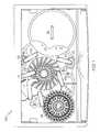
- FIG. 2is a perspective view of the optical subassembly of the automated immunochemistry analyzer and reagent system of FIG. 1 ;
- FIG. 5is a partial section view of the portion of the optical subassembly of FIG. 3 with an optical sensor in a first position and an optical pipettor disposed therein;
- FIG. 6is a partial section view of the portion of the optical subassembly of FIG. 3 with the optical sensor in a third position;
- FIG. 7is a partial section view of the portion of the optical subassembly of FIG. 3 with a pipettor disposed within the optical subassembly;
- FIG. 8is a perspective view of an in-line fiber optic light filter assembly in accordance with the teachings of the present application.
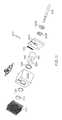
- FIG. 9is an exploded perspective view of the in-line fiber optic light filter assembly of FIG. 8 .
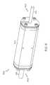
- FIG. 10is a perspective view of a fluorescence excitation subassembly in accordance with the teachings of the present application.
- FIG. 11is a section view of the fluorescence excitation subassembly of FIG. 10 ;
- FIG. 12is a top side section view of a bifurcated fiber optic cable routing system in accordance with the teachings of the present application.
- FIG. 13is a flowchart showing system control logic for the optical subassembly of FIG. 2 .
- the automated immunochemistry analyzer 100begins by first dispensing fluorescently labelled paramagnetic particles, or fluo-beads, into a cuvette located within the reaction rotor 106 .
- the fluo-beadsmay initially be located in the vortexer 102 and be transferred to the reaction rotor 106 by the R1 pipettor 104 .
- the R1 pipettor 104can aspirate a desired quantity of the fluo-bead mixture and transfer the aspirated quantity to the reaction rotor 106 where it is injected into the cuvette of the reaction rotor 106 .
- the optics pipettor 108may aspirate a test sample from the cuvette of the reaction rotor 106 and transfer the test sample to the optics box 110 .
- fluorescence and luminescence measurementscan be recorded.
- the initial recording of the fluorescence and luminescence signalcan be used as a baseline measurement for the fluorescence signal that can correspond to the initial concentration of fluo-beads in a sample.
- the multi rinse pipettor 112can rinse the cuvettes using a wash buffer.
- fluo-beadsmay be transferred from the vortexer 102 to a cuvette in the reaction rotor 106 via the R1 pipettor 104 .
- the R1 pipettor 104may aspirate a capture reagent from the reagent rotor 114 and inject the capture reagent into the cuvette located in the reaction rotor 106 .
- the single rinse pipettor 116may inject a rinse buffer to resuspend the fluo-bead. A substantial amount of the suspended fluo-bead may then be localized by magnets within the reaction rotor 106 over a period of time.
- the multi rinse pipettor 112may aspirate and dispose of a portion of the rinse buffer, leaving a portion of the fluo-beads localized within the cuvette.
- the multi rinse pipettor 112may proceed to inject a wash buffer into the cuvette of the reaction rotor 106 , resuspending the fluo-beads.
- the fluo-beadsmay again be localized by the magnets within the reaction rotor 106 to be followed by the multi rinse pipettor 112 aspirating and discarding a portion of the sample that was not localized from the cuvette in the reaction rotor 106 .
- a patient samplemay be contained in a sample tube on in the sample rotor 118 .
- the patient samplemay further be partially diluted with a sample diluent.
- the sample pipettor 120may aspirate a portion of the patient sample and inject the patient sample into the cuvette of the reaction rotor 106 to resuspend the fluo-beads.
- the cuvette containing the patient sample within the reaction rotor 106may then incubate the patient sample.
- the incubation temperaturecan be about 37 degrees Celsius +/ ⁇ about 0.2 degree Celsius while the incubation time can be about 37.75 minutes +/ ⁇ about 2 minutes.
- Another rinse cyclemay then occur by using the multi rinse pipettor 112 to again inject wash buffer into the cuvette and allow the fluo-beads to resuspend.
- Another fluo-bead localization processmay utilize the magnets within the reaction rotor 106 to localize the fluo-beads from the rest of the sample.
- the multi rinse pipettor 112may aspirate a portion of the sample that was not localized by the localization process.
- the R2 pipettor 122may aspirate a conjugate contained in a conjugate cuvette within the reagent rotor 114 .
- the R2 pipettor 122may then inject the previously aspirated conjugate into the cuvette of the reaction rotor 106 .
- the single rinse pipettor 116may inject a rinse buffer into the cuvette in the reaction rotor 106 .
- Another fluo-bead localization cyclemay be performed by allowing magnets within the reaction rotor 106 to substantially localize the fluo-beads within the cuvette.
- the multi rinse pipettor 112may aspirate and discard a portion of the sample within the cuvette that has not been localized during the localization cycle.
- Two more rinse cyclesmay be performed on the sample within the cuvette of the reaction rotor 106 .
- the multi rinse pipettor 112may inject a wash buffer to resuspend the fluo-beads within the cuvette.
- Another fluo-bead localization cyclemay localize the fluo-beads by locating the cuvette within close proximity to the magnets in the reaction rotor 106 over an adequate period of time.
- the multi rinse pipettor 112may aspirate and discard a portion of the sample that was not localized during the localization cycle.
- a second wash cyclemay then occur by using the multi rinse pipettor 112 to inject the wash buffer to resuspend the fluo-beads.
- Another localization cyclemay utilize the magnets within the reaction rotor 106 to localize the fluo-beads within the cuvette. After the localization process, the multi rinse pipettor 112 may again aspirate and discard a portion of the sample that was not localized during the localization cycle.
- the R2 pipettor 122may aspirate a portion of conjugate from the reagent rotor 114 and inject the conjugate into the mixed substrate container 124 creating a mixed substrate sample.
- the R2 pipettormay then aspirate the mixed substrate sample from the mixed substrate container 124 and inject the mixed substrate sample into the cuvette of the reaction rotor 106 , resuspending the fluo-bead with the mixed substrate sample.
- the sample in the cuvette of the reaction rotor 106may then be aspirated by the optics pipettor 108 and placed in the optics box 110 . After the optics box makes fluorescence and luminescence optical observations, the sample is discarded and the multi rinse pipettor rinses the cuvettes of the reaction rotor 106 in preparation for the next test.
- the optics pipettor 108could be transferred from the optics box 110 to a wash station 224 , from the wash station 224 to the reaction rotor 106 , from the reaction rotor 106 to the optics box 110 , or any combination thereof.
- the optical subassembly 200is a robotic device that can access a cuvette on the reaction rotor 106 of the automated immunochemistry analyzer 100 , aspirate a sample to a controlled position within the optically clear tip 208 , and position the clear tip 208 to a controlled position within the optics box 110 .
- the opaque body 210 connected to itis opaque in order to not introduce stray light into the optics box 110 .
- the disc feature 212 of the opaque body 210may mate in a reentrant fashion with the optics box 110 in order to prevent stray light from entering the box.
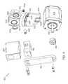
- a shutter stepper motor 218may be coupled to the optics box 110 with a light-tight seal similar to the reentrant seal 220 , allowing the shaft of the shutter stepper motor 218 to be disposed within the interior of the optics box 110 without allowing any external light to penetrate through the mounting location.
- a sealcould be achieved.
- the body of the shutter stepper motor 218could be coupled to the optics box and a gasket or O-ring could be positioned between the body of the shutter stepper motor 218 and the optics box 110 , preventing any exterior light from entering the interior portion of the optics box 110 at the seal.
- a reentrant sealcould utilize a series of circular peaks and valleys about the opening on the optics box 110 that mate to inverse peaks and valleys located on the shutter stepper motor 218 .
- the light tight seal between the shutter stepper motor 218 and the optics box 110can be achieved many different ways and the present disclosure should not be limited to the particular methods disclosed above.
- An electronics communication coupler 222may also be located on the optics box 110 .
- the electronics communication coupler 222can allow an external electrical connector to be electronically coupled to any electrical devices inside the optics box 110 .
- the electronics communication coupler 222could allow a system controller to become electronically coupled too, and thereby control, the electrical components within the optics box 110 .
- the electronics communication coupler 222can provide a light tight transition for wired electronic signals from the inside of the optics box 110 to the outside of the optics box 110 or vice versa.
- the electronics communication coupler 222may also be coupled to the optics box 110 in a plurality of ways that inhibit outside light infiltration.
- the electronic communication coupler 222can be coupled to the optics box 110 with opaque adhesives that may hold the electronic communications coupler 222 in place while simultaneously preventing any exterior light from entering the optics box 110 .
- a gasket or O-ringmay be disposed between the optics box 110 and the electronic communications coupler 222 to prevent any external light from entering the interior of the optics box 110 .
- a gasketcan be placed at every coupled edge, providing a tongue-and-groove relationship between the sections.
- the sectionscould be welded or machined in such a manner that the infiltration of outside light is substantially restricted.
- the corkscrew path of the tubing 338may ensure there is no direct path for any external light to shine into then optics box 110 through the tubing 338 .
- the interior of the tubing 338may be made of a non-reflective material that can substantially restrict the transmission of light through the interior portion of the tubing 338 . While one embodiment utilizes a corkscrew configuration of the tubing 338 , one skilled in the art would appreciate how many tubing configurations could be used to prevent light from having a direct path to the interior of the optics box. For instance, a zigzag, semicircular arc, or 90 degree bend among other things could be used in the tubing 338 to restrict light from entering the optics box 110 and this disclosure should not be limited to any particular orientation.
- the internal area created by the surrounding sections 302 , 304 , 306 , 308 , 310 , and 226may also contain a shutter mechanism 314 , an optical sensor 316 , a shutter sensor 318 , and an optical alignment plate 320 among other things.
- the third section 306may contain the optics pipettor reentrant seal 220 for the optics pipettor 108 .
- the clear tip 208 of the optics pipettor 108may be substantially disposed within the internal area 322 when the disc feature 212 is at least partially coupled to the optics pipettor reentrant seal 220 .
- the disc feature 212may be spaced an appropriate distance from the clear tip 208 to ensure that when the disc feature 212 contacts the optics pipettor reentrant seal 220 the clear tip 208 will be disposed in a desired location for making an optical reading. Further, the optics pipettor reentrant seal 220 may have a series of circular peaks and valleys that inversely correlate with the corresponding portion of the disc feature 212 .
- the peaks and valleys of the disc feature 212 and the optics pipettor reentrant seal 220at least partially couple to one another to substantially block any exterior light from entering the internal area 322 of the optics box 110 .
- the optical sensor 316may be coupled to the shutter mechanism 314 which is in turn coupled to the shutter stepper motor 218 .
- the optical sensor 316may be oriented so that the measurement side of the optical sensor 316 is oriented towards the optical alignment plate 320 .
- the optical sensor 316can be used to measure both fluorescence and luminescence signals from a source.
- the optical sensormay be a photomultiplier tube.
- the optical sensor 316may also be sensitive to light and require the internal area 322 to be substantially void of any light other than the light emitted from the desired source.
- the optical alignment plate 320can contain a plurality of reading positions for the optical sensor 316 .
- the optical alignment plate 320contains three reading positions.
- a first reading position 326could be for the luminescence reading of a sample within the clear tip 208 .
- a second reading position 328could be substantially blank and allow for a closed position that enables dark current and other electronic background measurements to be obtained.
- a third reading position 330could be for a fluorescence reading transmitted through fiber optic cables.
- a high sensitivity optical detectorsuch as a photomultiplier tube (PMT).
- the PMTIn the first reading position 326 , or the luminescence reading position, the PMT is in close proximity to the sample within the clear tip 208 and therefore accepts a significant fraction of the luminescence photons emitted from the sample.
- the third reading position 330or the fluorescence reading position, the PMT is in close proximity to one end of the receiving fiber bundle and captures most of the emission light emanating from its tip.
- the PMTcan be placed in the second reading position 328 , or an optically isolated position, where dark current and other electronic background measurements can be obtained.
- the optical sensor 316could be transitioned to and from each of the reading positions 326 , 328 , and 330 by the shutter mechanism 314 .
- the shutter mechanism 314could be coupled to a stepper motor, a pneumatic arm, or any other comparable mechanism that could allow for the movement of the optical sensor 316 .
- the shutter mechanism 314may also be in communication with the shutter sensor 318 .
- the shutter sensor 318may monitor the orientation of the shutter mechanism 314 and confirm or dictate desired movements of the shutter mechanism 314 .
- the shutter sensor 318can confirm that the optical sensor 316 is accurately aligned with any one of the plurality of reading positions 326 , 328 , and 330 on the optical alignment plate 320 .
- a cam systemcan be utilized between the shutter mechanism 314 and the optical alignment plate 320 .
- the cam systemcan allow the optical sensor 316 to be separated from, and coupled to, a reentrant seal located at each of the reading positions 326 , 328 , and 330 as the optical sensor 316 transitions from one reading position to the other.
- the cam systemcan incorporate a U-shaped channel 332 disposed within the surface of the optical alignment plate 320 .
- the U-shaped channel 332can follow an arc along the surface of the optical alignment plate 320 that is concentric with the pivotal center of the shutter stepper motor 218 shaft.
- the U-shaped channel 332may further have a detent or detents 334 located at the second reading position 328 and the third reading position 330 .
- the detent or detents 334may create a slightly greater recess in the optical alignment plate 320 than does the U-shaped channel 332 . While one embodiment may only show the detent or detents 334 at the second reading position 328 and the third reading position 330 , one skilled in the art can understand how the first reading position 326 could also have a detent and a U-shaped channel leading thereto.
- FIG. 4shows the shutter assembly 314 in an exploded view with the optics box 110 removed.
- the optical alignment plate 320may be pivotable about a pivot pin 404 . Further, the pivot pin 404 may be coupled to the interior portion of the fifth section 310 by a pivot pin retention plate 406 . The relationship between the pivot pin 404 , the pivot pin retention plate 406 , and the optical alignment plate 320 could be such that the optical alignment plate 320 may rotate about the axis of the pivot pin 404 .
- the optical alignment plate 320may also be coupled to one or more spring 408 .
- the one or more spring 408may have a first end that is coupled to the optical alignment plate 320 at a location on the opposite side as the U-shaped channel 332 and a second end that is coupled to an interior portion of the fifth section 310 .
- the U-shaped channel 332may interact with a cam pin 402 located on a shutter mechanism coupler 412 to maintain the particular orientation between the optical alignment plate 320 and the optical sensor 316 . More specifically, when the cam pin 402 is disposed in the U-shaped channel 332 , the cam pin 402 may maintain a slight gap between the optical alignment plate 320 and the optical sensor 316 . However, when the cam pin 402 enters the detent or detents 334 , the optical alignment plate 320 may rotate towards the optical sensor 316 about the axis of the pivot pin 404 .
- the optical alignment plate 320may become oriented a sufficient distance from the optical sensor 316 to allow the optical sensor 316 to contact a photo sensor seal 410 around any of the first, second, or third reading positions 326 , 328 , and 330 .
- the cam pin 402may exit the detent or detents 334 and slightly rotate the optical alignment plate 320 away from the optical sensor 316 about the pivot pin 404 axis.
- the shutter mechanism 314may be coupled to the shutter stepper motor 218 by a hub 414 .
- the hub 414may be substantially cylindrical with an inner through hole that may be slightly greater than a stepper motor shaft 416 outer diameter.
- the hub 414may also have a means for compressibly coupling the hub 414 to the stepper motor shaft 416 .
- the hub 414may have at least one through hole that is parallel to the inner through hole that allow the hub 414 to be removably coupled to the shutter mechanism 314 .
- the end of the shutter mechanism 314 that is opposite of the hub 414may be coupled to the shutter mechanism coupler 412 .
- the shutter mechanism coupler 412may further couple the optical sensor 316 to the shutter mechanism 314 .
- the cam pin 402may be coupled to a shutter mechanism coupler 312 to ensure proper alignment between the optical alignment plate 320 and the optical sensor 316 .
- the shutter mechanism 314can allow the optical sensor 316 to measure luminescence and fluorescence signals from a single sample while minimizing cross-talk from the fluorescence excitation light source.
- the close proximity of the optical sensor 316 to the clear tip 208may allow the optical sensor 316 to analyze the luminescence of a sample located within the clear tip 208 of the optics pipettor 108 .
- Background lightcan be any undesired light that may enter the optics box 110 from an external source.
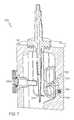
- FIG. 7illustrates how fluorescence excitation light enters the optics box 110 .
- FIG. 7shows a partial section view 700 of the optics box 110 with the optics pipettor 108 disposed therein.
- the clear tip 208may be located within close proximity to the common terminus end 1206 of the bifurcated fiber optic cable 1202 .
- the proximity of the common terminus end 1206 to the clear tip 208 within the optics box 110may allow the fluorescence excitation light emitted from the common terminus end 1206 to be projected onto a sample located within the clear tip 208 .
- the light trap 702may substantially inhibit any fluorescence excitation light projected from the common terminus end 1206 from being reflected off of the interior surfaces of the optics box 110 and into the first transmission fiber optic bundle 1214 of the common terminus end 1206 .
- the light trap 702may prevent reflection of the fluorescence excitation light by allowing any residual fluorescence excitation light not absorbed by the sample within the clear tip 208 to enter the light trap 702 through a light trap opening 704 .
- a diverter 706may disperse the fluorescence excitation light about an interior region 708 of the light trap 702 .
- the diverter 706 and the interior region 708can be comprised of a substantially non-reflective surface that prevents any light introduced into the light trap 702 from being reflected out of the light trap 702 .
- FIGS. 10 and 11illustrate the fluorescence excitation source. More particularly, FIG. 10 shows a perspective view of a fluorescence excitation assembly 1000 .
- the fluorescence excitation assembly 1000is mounted in a separate enclosure from the optics box 110 .
- the light sourceis a high-powered LED with spectral output that will efficiently excite a fluorescent label on paramagnetic particles within a sample, although other light sources, such as lasers or laser diodes can be used as well.
- a lens, mounted to an LED circuit boardcan focus the light onto the end of a fiber optic bundle. Before entering the fiber, the excitation light can pass through a narrow band pass optical filter so that out-of-band light, a potential source of background radiation, can be greatly reduced.
- the first and second fiber optic covers 1006 , 1008may be substantially U-shaped plates that are parallel to one another and oriented 180 degrees to one another. This particular orientation may allow the first and second fiber optic covers 1006 , 1008 to couple the bifurcated fiber optic cable 1202 to the fluorescence excitation assembly 1000 without allowing any external light into, or out of, the interior region of the fluorescence excitation assembly 1000 .
- FIG. 11shows an expanded view 1100 of the fluorescence excitation assembly 1000 .
- the interior region of the body 1002may further house a light sensor 1102 , an excitation O-ring 1104 , an excitation light filter 1106 , an excitation lens 1108 , and a light-emitting diode (LED) 1110 .
- the LED 1110may be positioned with one surface substantially contacting the heat sink 1012 and with a light-emitting portion substantially facing the interior region of the body 1002 .
- the LED 1110may be coupled to the heat sink 1012 with a thermal coupling compound that allows a substantial amount of the heat generated by the LED 1110 to be transferred to the heat sink 1012 .
- the heat sink 1012can maintain a desired operating temperature of the LED 1110 .
- the LED 1110may be oriented to emit light through the excitation lens 1108 .
- the excitation lens 1108may in turn focus the light emitted by the LED 1110 so that it is substantially directed onto the fluorescence excitation emission end 1204 of the bifurcated fiber optic cable 1202 .
- the excitation light filter 1106may be a fluorescence excitation filter that corresponds with an excitation spectrum of the fluo-bead sample located within the clear tip 208 at the common terminus end 1206 .
- excitation O-ring 1104may be positioned within the interior region of the body 1002 between a holder 1114 and the excitation light filter 1106 .
- the O-ringmay maintain the correct position of the light filter with respect to the LED 1110 and the emissions fiber optic cable bundle 1216 .
- the light sensor 1102may be coupled to the first cover 1004 and oriented to allow the light sensor 1102 to measure the light emissions in the interior region of the fluorescence excitation assembly 1000 .
- the light sensor 1102may be disposed behind the holder 1114 . Further, the holder 1114 may have a light path through hole 1116 that substantially corresponds to the location of the light sensor 1102 and allows the light sensor 1102 to substantially observe the state of the LED 1110 .
- the light sensor 1102may also be electronically coupled to the control board 1010 .
- the control board 1010may monitor measurements observed by the light sensor 1102 to determine the fluorescence excitation assembly's 1000 interior conditions. For example, the light sensor 1102 may be utilized by the control board 1010 to determine whether LED 1110 is emitting light. Further, the light sensor 1102 could be used to determine and regulate the intensity of the light emitted by the LED 1110 .
- the control board 1010can further be in electronic communication with a system control that may control the intensity and timing of the LED 1110 .
- the optical systemutilizes a bifurcated fiber optic bundle, which includes two fiber optic bundles tied together at a common terminus proximal to the optical sample with one bundle transmitting fluorescence excitation light from a light source to the sample, and with the other bundle receiving fluorescence emission light from the sample at the common terminus and transmitting that light to an optical detector.
- the fiber opticsmay include two separate fiber optic bundles, one to transmit excitation light from source to sample, and the other oriented at an angle, such as, for instance, 90.degree., with respect to the excitation bundle, for receiving the fluorescence emission light and transmitting it to the optical detector.
- the first and second transmission fiber optic cable bundle 1214 , 1215may utilize fiber optic cables to connect the common terminus end 1206 to the transmission end 1208 .
- the fiber optic filter housing 1212between the common terminus end 1206 and the transmission end 1208 is the fiber optic filter housing 1212 .
- FIGS. 8 and 9illustrate with more detail the fiber optic filter housing 1212 .
- FIG. 8specifically shows a perspective view 800 of the fiber optic filter housing 1212 and how the fiber optic filter housing 1212 can be placed in-line with the first and second transmission fiber optic cable bundle 1214 , 1215 .
- the fiber optic filter housing 1212may have an output end 802 and an input end 804 .
- the input end 804may be an input location where transmissions along the first transmission fiber optic cable bundle 1214 are input into the fiber optic filter housing 1212 .
- the output end 802 of the fiber optic filter housing 1212may be an output location where transmissions are output to the second transmission fiber optic cable bundle 1215 .
- FIG. 9is an exploded view 900 of the fiber optic filter housing 1212 .
- the input end 804illustrates how the first transmission fiber optic cable bundle 1214 can enter the fiber optic filter housing 1212 .
- a first entrance plate 902 and a second entrance plate 904may substantially couple the first transmission fiber optic cable bundle 1214 to the fiber optic filter housing 1212 .
- Both the first and the second entrance plate 902 , 904may be substantially U-shaped and provide a central cavity that is substantially sized to allow the first transmission fiber optic cable bundle 1214 to be disposed therein.
- the first entrance plate 902may be parallel to and concentric with the second entrance plate 904 with the U-shaped portions being oriented 180 degrees opposite of one another.
- the 180 degree orientation of the first and second entrance plate 902 , 904can create a substantially circular through hole through the center of the first and second entrance plates 902 , 904 when they are coupled to one another.
- the through holemay be substantially the same diameter as a cross section of the first transmission fiber optic cable bundle 1214 .
- the entrance seal retention plate 906may have a through hole that is concentric with the first and second entrance plate 902 , 904 . Further, the entrance seal retention plate 906 through hole may be substantially the same size as the first and second entrance plate 902 , 904 through hole.
- the entrance seal retention plate 906 through holemay also correspond with an entrance O-ring 908 .
- the entrance O-ring 908may have a diameter large enough to allow the entrance O-ring 908 to encircle the first transmission fiber optic cable bundle 1214 .
- the entrance O-ring 908may further become disposed between the entrance seal retention plate 906 and an entrance end cap 910 .
- the entrance end cap 910may also have a first partial through hole sufficiently sized to allow the first transmission fiber optic cable bundle 1214 to be substantially disposed therein.
- the first partial through holemay be sized to terminate at a second partial through hole that may have a slightly smaller diameter than the first partial through hole.
- the first and second partial through holes of the entrance end cap 910may allow the first transmission fiber optic cable bundle 1214 to be substantially located within, but not all the way through, the entrance end cap 910 . Further, the first transmission fiber optic cable bundle 1214 may fit into the entrance end cap 910 until it contacts the second partial through hole.
- the slightly smaller diameter of the second partial through holemay ensure that the first transmission fiber optic cable bundle 1214 is correctly positioned within the fiber optic filter housing 1212 while simultaneously allowing the first transmission fiber optic cable bundle 1214 to project a light source through the fiber optic filter housing 1212 .
- the entrance end cap 910may also have a recessed portion that allows the entrance O-ring 908 to be at least partially disposed within the recessed portion when the entrance seal retention plate 906 is coupled to the entrance end cap 910 .
- the first transmission fiber optic cable bundle 1214may be disposed within the through hole of the entrance end cap 910 .
- the entrance O-ring 908 , the entrance seal retention plate 906 , and the first and second entrance plate 902 , 904may be coupled to the entrance end cap 910 with the first transmission fiber optic cable bundle 1214 disposed therein.
- the entrance O-ring 908can substantially seal the first transmission fiber optic cable bundle 1214 to the entrance end cap 910 .
- the entrance end cap 910may further be coupled to the fiber optic filter housing 1212 .
- the first transmission fiber optic cable bundle 1214When the first transmission fiber optic cable bundle 1214 is disposed within the entrance end cap 910 , the entrance O-ring 908 , the entrance seal retention plate 906 , and the first and second entrance plate 902 , 904 , the first transmission fiber optic cable bundle 1214 may be held in substantially concentric alignment with a central axis 912 .
- a first internal O-ring 914After the entrance end cap 910 , a first internal O-ring 914 , a first filter 916 , a first aperture 918 , a lens holder 920 , a lens 922 , a second aperture 924 , a third aperture 926 , a second filter 928 , a third filter 930 and a second internal O-ring 932 may all be disposed within the fiber optic filter housing 1212 .
- the first internal O-ring 914can ensure the first filter 916 remains disposed in alignment with the first transmission fiber optic cable bundle 1214 .
- the lens holder 920may hold the first aperture 918 .
- the second aperture 924 , the third aperture 926 , the second filter 928 , the third filter 930 , and the second internal O-ring 932may be substantially circular and contain through holes.
- the second aperture 924may have a slightly smaller external diameter than the third aperture 926 .
- the fiber optic filter housing 1212may have corresponding diameter partial through holes that allow the second and the third apertures 924 , 926 to be particularly spaced within the fiber optic filter housing 1212 as they are placed within the corresponding partial through hole.
- the second and third filter 928 , 930may be maintained within the fiber optic filter housing 1212 at least partially by the second internal O-ring 932 that may contact an exit cap 934 .
- the exit cap 934may be located at the output end 802 of the fiber optic filter housing 1212 .
- the output end 802may have an exit O-ring 936 that can seal the second transmission fiber optic cable bundle 1215 at the output end 802 .
- the exit O-ring 936can seal the second transmission fiber optic cable bundle 1215 by coupling the second transmission fiber optic cable bundle 1215 to the exit cap 934 with an exit seal retention plate 938 , and a first and second exit plate 940 , 942 .
- the output end 802can retain the second transmission fiber optic cable bundle 1215 in alignment with the fiber optic filter housing 1212 in substantially the same way as the input end 804 .
- the three filters 916 , 928 , and 930may be a notch filter to remove the excitation light, a long pass filter to eliminate the luminescence signal, and an emission filter to further reduce any out of band or wide angle light from the fluorescence emission signal.
- the visual response of the samplemay be captured by the first transmission fiber optic cable bundle 1214 at the common terminus end 1206 .
- the visual responsemay further travel through the first transmission fiber optic cable bundle 1214 from the common terminus end 1206 to the fiber optic filter housing 1212 .
- the visual responseis projected through the first filter 916 , which may be a notch filter that can attenuate undesired frequencies from the visual response, and the first aperture 918 onto the lens 922 .
- the lens 922may further modify the visual response and project the signal through the second and third aperture 924 , 926 , and through the second and third filter 928 , 930 .
- the filtered visual responsemay be projected onto the output terminus of the second transmission fiber optic cable bundle 1215 .
- the second transmission fiber optic cable bundle 1215may then carry the filtered visual response to the transmission end 1208 terminus.
- the transmission end 1208 terminusmay be disposed within close proximity to, and in alignment with, the optical sensor 316 when the optical sensor 316 is in the third reading position 330 .
- the transmission end 1208 of the second transmission fiber optic cable bundle 1215may than project the readings observed from the sample within the clear tip 208 to the optical sensor 316 .
- FIG. 13illustrates how the pipette transfer arm 204 , the shutter stepper motor 218 , the shutter sensor 318 , the optical sensor 316 , the LED 1110 , and the light sensor 1102 may be electrically coupled too, and controlled by, a system controller 1300 .
- the method of controlling the automated analyzer 100can initially begin with orienting the pipette transfer arm 204 in a neutral position. From the neutral position, in a first step 1302 , the system controller may move the pipette transfer arm 204 to orient the optics pipettor 108 in a position inside a cuvette located in the reaction rotor 106 .
- the system controllermay send a command to the optics pipettor 108 to aspirate a volume of a sample from the cuvette in a second step 1304 .
- the system controllermay then withdraw the optics pipettor 108 from the cuvette in a third step 1306 .
- the system controllermay command the optics pipettor to aspirate a volume of air to position the sample in the clear tip 208 .
- the system controllermay move the optics pipettor 108 to a location so that the clear tip 208 is disposed within the optics box 110 in a fifth step 1310 .
- the system controllermay send a signal to the shutter stepper motor 218 and the shutter sensor 318 to transition the optical sensor 316 from the second reading position 328 to the first reading position 326 per a sixth step 1312 .
- the system controllermay obtain a luminescence reading from the sample by recording inputs from the optical sensor 316 .
- the system controllermay send a command to the stepper motor 218 and the shutter sensor 318 to transition the optical sensor 316 to the third reading position 330 in an eighth step 1316 .
- the system controllermay enable the LED 1110 to emit fluorescence excitation light in a ninth step 1318 .
- the system controllermay give the LED 1110 substantial time to stabilize before the system controller will count optical sensor 316 pulses in a time interval 1320 . In one embodiment, it may take about 10 milliseconds for the LED 1110 to stabilize and the optical sensor 316 may take readings for 100 milliseconds.
- the light sensor 1102may read the LED 1110 reference signal in a time interval.
- the system controllermay execute a twelfth step 1322 where it commands the stepper motor 218 and the shutter sensor 318 to orient the optical sensor 316 in the second position 328 .
- the system controllermay withdraw the optics pipettor 108 from the optics box 110 and transfer the optics pipettor 108 to the wash station 224 . While the optics pipettor 108 is located at the wash station 224 , the system controller may send a command to the optics pipettor 108 to flush the sample by dispensing a volume of air during a fourteenth step 1326 .
- the system controllermay execute a wash cycle during a fifteenth step 1328 where the optics pipettor 108 utilizes a system liquid to wash the optics pipettor 108 clear tip 208 .
- the system controllermay execute a final air aspiration in a sixteenth step 1330 to remove any remaining system liquid from the clear tip 208 .
- the system controllermay move the optics pipettor 108 back to a neutral position in anticipation for the next cycle during a seventeenth step 1332 .
- the system controllercan execute the commands shown in FIG. 13 utilizing a plurality of forms known by those skilled in the art.
- the system controllercan execute commands on a time scale with predefined intervals for each command performed by the system controller.
- the system controllercould also utilize the various sensors located throughout the system to determine the appropriate time to move to the next step. For instance, the shutter sensor 318 may communicate to the system controller when the shutter mechanism 314 is in the correct orientation, at which point the system controller may initiate a time sequence prior to transitioning to the next step.
- the system controllercould control the automated analyzer 100 such as time sequence commands, proximity sensors, optical sensors, and the like and this disclosure should not be limited to any one embodiment.
Landscapes
- Health & Medical Sciences (AREA)
- Life Sciences & Earth Sciences (AREA)
- Immunology (AREA)
- Chemical & Material Sciences (AREA)
- Engineering & Computer Science (AREA)
- Physics & Mathematics (AREA)
- Hematology (AREA)
- Urology & Nephrology (AREA)
- Molecular Biology (AREA)
- Biomedical Technology (AREA)
- Biochemistry (AREA)
- Analytical Chemistry (AREA)
- Pathology (AREA)
- General Physics & Mathematics (AREA)
- General Health & Medical Sciences (AREA)
- Medicinal Chemistry (AREA)
- Cell Biology (AREA)
- Microbiology (AREA)
- Food Science & Technology (AREA)
- Biotechnology (AREA)
- Chemical Kinetics & Catalysis (AREA)
- Nuclear Medicine, Radiotherapy & Molecular Imaging (AREA)
- Virology (AREA)
- Tropical Medicine & Parasitology (AREA)
- Proteomics, Peptides & Aminoacids (AREA)
- Optics & Photonics (AREA)
- Plasma & Fusion (AREA)
- Rheumatology (AREA)
- Rehabilitation Therapy (AREA)
- Mathematical Physics (AREA)
- Theoretical Computer Science (AREA)
- Spectroscopy & Molecular Physics (AREA)
- Investigating, Analyzing Materials By Fluorescence Or Luminescence (AREA)
- Investigating Or Analysing Materials By The Use Of Chemical Reactions (AREA)
- Automatic Analysis And Handling Materials Therefor (AREA)
- Measuring Or Testing Involving Enzymes Or Micro-Organisms (AREA)
- Robotics (AREA)
Abstract
Description
Claims (20)
Priority Applications (3)
| Application Number | Priority Date | Filing Date | Title |
|---|---|---|---|
| US14/634,061US9766233B2 (en) | 2013-03-15 | 2015-02-27 | Device and associated methods for performing luminescence and fluorescence measurements of a sample |
| US15/682,780US10955346B2 (en) | 2013-03-15 | 2017-08-22 | Device and associated methods for performing luminescence and fluorescence measurements of a sample |
| US17/208,169US20210293709A1 (en) | 2013-03-15 | 2021-03-22 | Device and associated methods for performing luminescence and fluorescence measurements of a sample |
Applications Claiming Priority (4)
| Application Number | Priority Date | Filing Date | Title |
|---|---|---|---|
| US201361791295P | 2013-03-15 | 2013-03-15 | |
| US201361791879P | 2013-03-15 | 2013-03-15 | |
| US14/215,861US9075055B2 (en) | 2013-03-15 | 2014-03-17 | Device and associated methods for performing luminescence and fluorescence measurements of a sample |
| US14/634,061US9766233B2 (en) | 2013-03-15 | 2015-02-27 | Device and associated methods for performing luminescence and fluorescence measurements of a sample |
Related Parent Applications (1)
| Application Number | Title | Priority Date | Filing Date |
|---|---|---|---|
| US14/215,861ContinuationUS9075055B2 (en) | 2013-03-15 | 2014-03-17 | Device and associated methods for performing luminescence and fluorescence measurements of a sample |
Related Child Applications (1)
| Application Number | Title | Priority Date | Filing Date |
|---|---|---|---|
| US15/682,780ContinuationUS10955346B2 (en) | 2013-03-15 | 2017-08-22 | Device and associated methods for performing luminescence and fluorescence measurements of a sample |
Publications (2)
| Publication Number | Publication Date |
|---|---|
| US20150177146A1 US20150177146A1 (en) | 2015-06-25 |
| US9766233B2true US9766233B2 (en) | 2017-09-19 |
Family
ID=50686181
Family Applications (13)
| Application Number | Title | Priority Date | Filing Date |
|---|---|---|---|
| US14/215,861ActiveUS9075055B2 (en) | 2013-03-15 | 2014-03-17 | Device and associated methods for performing luminescence and fluorescence measurements of a sample |
| US14/215,720ActiveUS9658225B2 (en) | 2013-03-15 | 2014-03-17 | Automated immunoanalyzer system for performing diagnostic assays for allergies and autoimmune diseases |
| US14/634,011Active2034-11-01US9753033B2 (en) | 2013-03-15 | 2015-02-27 | Device and associated methods for performing luminescence and fluorescence measurements of a sample |
| US14/634,061Active2034-08-13US9766233B2 (en) | 2013-03-15 | 2015-02-27 | Device and associated methods for performing luminescence and fluorescence measurements of a sample |
| US14/673,698Expired - Fee RelatedUS9651550B2 (en) | 2013-03-15 | 2015-03-30 | Automated immunoanalyzer system for performing diagnostic assays for autoimmune and infectious diseases |
| US14/673,647Expired - Fee RelatedUS9658226B2 (en) | 2013-03-15 | 2015-03-30 | Automated immunoanalyzer system for performing diagnostic assays for autoimmune and infectious diseases |
| US15/482,460Expired - Fee RelatedUS10732110B2 (en) | 2013-03-15 | 2017-04-07 | Automated immunoanalyzer system for performing diagnostic assays for autoimmune and infectious diseases |
| US15/482,537Expired - Fee RelatedUS10732111B2 (en) | 2013-03-15 | 2017-04-07 | Automated immunoanalyzer system for performing diagnostic assays for allergies and autoimmune diseases |
| US15/482,508Expired - Fee RelatedUS10739262B2 (en) | 2013-03-15 | 2017-04-07 | Automated immunoanalyzer system for performing diagnostic assays for autoimmune and infectious diseases |
| US15/681,647Active2034-06-02US11204323B2 (en) | 2013-03-15 | 2017-08-21 | Device and associated methods for performing luminescence and fluorescence measurements of a sample |
| US15/682,780Expired - Fee RelatedUS10955346B2 (en) | 2013-03-15 | 2017-08-22 | Device and associated methods for performing luminescence and fluorescence measurements of a sample |
| US16/940,947PendingUS20200371029A1 (en) | 2013-03-15 | 2020-07-28 | Automated immunoanalyzer system for performing diagnostic assays for autoimmune and infectious diseases |
| US17/208,169AbandonedUS20210293709A1 (en) | 2013-03-15 | 2021-03-22 | Device and associated methods for performing luminescence and fluorescence measurements of a sample |
Family Applications Before (3)
| Application Number | Title | Priority Date | Filing Date |
|---|---|---|---|
| US14/215,861ActiveUS9075055B2 (en) | 2013-03-15 | 2014-03-17 | Device and associated methods for performing luminescence and fluorescence measurements of a sample |
| US14/215,720ActiveUS9658225B2 (en) | 2013-03-15 | 2014-03-17 | Automated immunoanalyzer system for performing diagnostic assays for allergies and autoimmune diseases |
| US14/634,011Active2034-11-01US9753033B2 (en) | 2013-03-15 | 2015-02-27 | Device and associated methods for performing luminescence and fluorescence measurements of a sample |
Family Applications After (9)
| Application Number | Title | Priority Date | Filing Date |
|---|---|---|---|
| US14/673,698Expired - Fee RelatedUS9651550B2 (en) | 2013-03-15 | 2015-03-30 | Automated immunoanalyzer system for performing diagnostic assays for autoimmune and infectious diseases |
| US14/673,647Expired - Fee RelatedUS9658226B2 (en) | 2013-03-15 | 2015-03-30 | Automated immunoanalyzer system for performing diagnostic assays for autoimmune and infectious diseases |
| US15/482,460Expired - Fee RelatedUS10732110B2 (en) | 2013-03-15 | 2017-04-07 | Automated immunoanalyzer system for performing diagnostic assays for autoimmune and infectious diseases |
| US15/482,537Expired - Fee RelatedUS10732111B2 (en) | 2013-03-15 | 2017-04-07 | Automated immunoanalyzer system for performing diagnostic assays for allergies and autoimmune diseases |
| US15/482,508Expired - Fee RelatedUS10739262B2 (en) | 2013-03-15 | 2017-04-07 | Automated immunoanalyzer system for performing diagnostic assays for autoimmune and infectious diseases |
| US15/681,647Active2034-06-02US11204323B2 (en) | 2013-03-15 | 2017-08-21 | Device and associated methods for performing luminescence and fluorescence measurements of a sample |
| US15/682,780Expired - Fee RelatedUS10955346B2 (en) | 2013-03-15 | 2017-08-22 | Device and associated methods for performing luminescence and fluorescence measurements of a sample |
| US16/940,947PendingUS20200371029A1 (en) | 2013-03-15 | 2020-07-28 | Automated immunoanalyzer system for performing diagnostic assays for autoimmune and infectious diseases |
| US17/208,169AbandonedUS20210293709A1 (en) | 2013-03-15 | 2021-03-22 | Device and associated methods for performing luminescence and fluorescence measurements of a sample |
Country Status (8)
| Country | Link |
|---|---|
| US (13) | US9075055B2 (en) |
| EP (3) | EP2972230B1 (en) |
| JP (3) | JP6553020B2 (en) |
| CN (4) | CN105308458B (en) |
| AU (3) | AU2014232882B2 (en) |
| CA (2) | CA2905178A1 (en) |
| HK (2) | HK1220759A1 (en) |
| WO (2) | WO2014145619A1 (en) |
Cited By (1)
| Publication number | Priority date | Publication date | Assignee | Title |
|---|---|---|---|---|
| US10732111B2 (en) | 2013-03-15 | 2020-08-04 | Hycor Biomedical, Llc | Automated immunoanalyzer system for performing diagnostic assays for allergies and autoimmune diseases |
Families Citing this family (34)
| Publication number | Priority date | Publication date | Assignee | Title |
|---|---|---|---|---|
| US8866912B2 (en) | 2013-03-10 | 2014-10-21 | Pelican Imaging Corporation | System and methods for calibration of an array camera using a single captured image |
| EP3147670B1 (en)* | 2014-05-19 | 2022-09-28 | System Instruments Co., Ltd. | Automatic analyzing system |
| US10661268B2 (en)* | 2014-06-30 | 2020-05-26 | Beacon Technologies, LLC | Pipette tip system, device and method of use |
| EP3262397B1 (en)* | 2015-02-27 | 2022-06-08 | Hycor Biomedical, LLC | Apparatuses for suspending and washing the contents of a plurality of cuvettes |
| CN107548461A (en)* | 2015-03-30 | 2018-01-05 | Hycor生物医学有限责任公司 | Immunoassay instrument system for the automation of the diagnostic measure that performs autoimmune disease and infectious diseases |
| EP4582813A3 (en) | 2015-06-26 | 2025-08-27 | Abbott Laboratories | Rotating device in a diagnostic analyzer |
| EP3322533A4 (en)* | 2015-07-15 | 2019-03-20 | Hycor Biomedical, LLC | INSTRUMENT THAT CAN BE CUSTOMIZED |
| EP3325965B1 (en)* | 2015-07-23 | 2022-02-09 | Hycor Biomedical, Inc. | On-board kitting |
| CN105353134A (en)* | 2015-11-17 | 2016-02-24 | 苏州浩欧博生物医药有限公司 | Kit detecting dog-hair allergen specific IgE antibody and method |
| CN105353133A (en)* | 2015-11-17 | 2016-02-24 | 苏州浩欧博生物医药有限公司 | Kit detecting dermatophagoides-farinae allergen specific IgE antibody and method |
| CN105403692A (en)* | 2015-11-17 | 2016-03-16 | 苏州浩欧博生物医药有限公司 | Kit and method for detecting dermatophagoides pteronyssinus allergen specificity IgE antibody |
| TW201832726A (en)* | 2016-11-01 | 2018-09-16 | 美商海科生醫有限責任公司 | Immunoassay system capable of suggesting assays based on input data |
| CN109470862B (en)* | 2016-11-22 | 2021-12-03 | 科美博阳诊断技术(上海)有限公司 | Immunoassay method, system and kit for identifying immunoassay |
| CN107389615B (en)* | 2016-12-20 | 2020-03-24 | 苏州赛德福科学仪器有限公司 | Evaporation light detection device and evaporation light measurement method based on same |
| CN107703123A (en)* | 2017-09-15 | 2018-02-16 | 江苏浩欧博生物医药股份有限公司 | A kind of chemical luminescent analysis reagent kid of serum tryptase and preparation method thereof and detection method |
| EP4582806A3 (en) | 2017-09-19 | 2025-08-13 | Beckman Coulter, Inc. | Analog light measuring and photon counting in chemiluminescence measurements |
| CN107766772B (en)* | 2017-11-23 | 2024-05-17 | 安派科生物医学科技(丽水)有限公司 | Sample inputting device |
| CN108593949B (en)* | 2018-02-11 | 2024-01-26 | 金博特(北京)生物科技有限公司 | Chemiluminescence immunity analyzer |
| WO2020044151A1 (en) | 2018-08-29 | 2020-03-05 | CANNAVALE, Giuseppe | System and method for solid phase analysis of biological samples |
| IT201800008227A1 (en)* | 2018-08-29 | 2020-02-29 | Cannavale Giuseppe | Method and system for the determination of total or direct immunoglobulins against allergens or other molecules in aqueous samples |
| US12163885B2 (en) | 2018-08-31 | 2024-12-10 | Shimadzu Corporation | Analysis device, analysis method, trace liquid collection device, and trace liquid collection method |
| CN109030809B (en)* | 2018-10-31 | 2021-08-20 | 蓝怡科技集团股份有限公司 | Allergen IgE antibody automatic analyzer |
| WO2020157789A1 (en)* | 2019-01-28 | 2020-08-06 | 株式会社島津製作所 | Analysis device |
| CN110596371B (en)* | 2019-09-20 | 2023-04-07 | 郑州安图生物工程股份有限公司 | Method for evaluating magnetic bead recovery rate and reagent needle precision of full-automatic chemiluminescence determinator and kit |
| CN111518780B (en)* | 2020-06-04 | 2022-06-14 | 郑州伊美诺生物技术有限公司 | Preparation method of apo-horseradish peroxidase |
| US11480565B2 (en)* | 2020-06-12 | 2022-10-25 | Bio-Rad Laboratories, Inc. | Automated immunoassay |
| GB202009823D0 (en)* | 2020-06-26 | 2020-08-12 | Stimson William Howard | Automated quantitative assay device and a method of performing the quantitative assays |
| CN112748248B (en)* | 2020-12-23 | 2022-06-14 | 郑州安图生物工程股份有限公司 | Milk allergen specificity IgE detect reagent box |
| CN112666154A (en)* | 2021-01-26 | 2021-04-16 | 安图实验仪器(郑州)有限公司 | Optical signal detection device |
| JP7693173B2 (en)* | 2021-09-24 | 2025-06-17 | 学校法人杏林学園 | Method for detecting macadamia nut allergen-specific IgE, in vitro diagnostic agent for diagnosing macadamia nut allergy, kit for detecting macadamia nut allergen-specific IgE, and method for detecting macadamia nut allergen |
| IT202200010064A1 (en)* | 2022-05-16 | 2023-11-16 | Optoelettronica Italia S R L | DEVICE AND METHOD FOR THE DETECTION OF BIOMOLECULES |
| WO2025155731A1 (en)* | 2024-01-16 | 2025-07-24 | Beckman Coulter, Inc. | Alternative substrate pack for automated clinical analyzer and methods of use |
| WO2025155701A1 (en)* | 2024-01-16 | 2025-07-24 | Beckman Coulter, Inc. | Automated clinical analyzer with alternative substrate and method of use |
| CN118501432B (en)* | 2024-07-18 | 2024-09-27 | 山东省动物疫病预防与控制中心(山东省人畜共患病流调监测中心) | Brucellosis CF-ELISA Antibody Detection Kit |
Citations (135)
| Publication number | Priority date | Publication date | Assignee | Title |
|---|---|---|---|---|
| US3628682A (en) | 1970-06-29 | 1971-12-21 | Beckman Instruments Inc | Lighttight sample introduction system |
| US3729556A (en) | 1969-04-29 | 1973-04-24 | O Schwarz | Prophylactic preparation for preventing sensitization of rh-negative mothers by rh-positive fetal erythrocytes |
| US4291230A (en)* | 1979-03-07 | 1981-09-22 | Baxter Travenol Laboratories, Inc. | Fluorometric analyzer including shutter means for simultaneously shielding sample and photodetector during sample change |
| US4778751A (en) | 1986-05-12 | 1988-10-18 | Diagnostic Products Corporation | Method for measuring antigens or antibodies in biological fluids using ligand labeled antigens or ligand labeled antibodies |
| US4849337A (en) | 1983-01-31 | 1989-07-18 | Minnesota Mining And Manufacturing Company | Assaying allergen specific IgE levels with fluorogenic enzyme labeled antibody |
| EP0353592A2 (en) | 1988-08-02 | 1990-02-07 | Abbott Laboratories | Reaction cartridge and carousel for biological sample analyzer |
| EP0355849A2 (en) | 1988-08-26 | 1990-02-28 | Hitachi, Ltd. | Method and apparatus for automatic measurement of fluorescence |
| US5001049A (en) | 1989-01-23 | 1991-03-19 | Boehringer Mannheim Gmbh | Method for determination of HIV specific antibodies |
| US5395752A (en) | 1993-03-19 | 1995-03-07 | Ciba Corning Diagnostics Corp. | Long emission wavelength chemiluminescent compounds and their use in test assays |
| US5395938A (en) | 1992-08-21 | 1995-03-07 | Nichols Institute Diagnostics | Biotinylated chemiluminescent labels and their conjugates, assays and assay kits |
| US5468453A (en) | 1993-06-14 | 1995-11-21 | Cirrus Diagnostics, Inc. | Low carryover pipette probe |
| US5543332A (en) | 1991-07-04 | 1996-08-06 | Immunodex K/S | Water-soluble, polymer-based reagents and conjugates comprising moieties derived from divinyl sulfone |
| US5583001A (en) | 1989-03-29 | 1996-12-10 | E. I. Du Pont De Nemours And Company | Method for detection or quantitation of an analyte using an analyte dependent enzyme activation system |
| US5643566A (en) | 1982-09-23 | 1997-07-01 | Cetus Corporation | Formulation processes for lipophilic proteins |
| US5672475A (en) | 1993-05-06 | 1997-09-30 | Chiron Diagnostics Corporation | Mixed luminescent conjugate test |
| US5674698A (en) | 1992-09-14 | 1997-10-07 | Sri International | Up-converting reporters for biological and other assays using laser excitation techniques |
| US5686253A (en) | 1990-11-20 | 1997-11-11 | Behringwerke Ag | Method of stabilizing enzyme conjugates |
| US5690907A (en) | 1995-06-08 | 1997-11-25 | The Jewish Hospital Of St. Louis | Avidin-biotin conjugated emulsions as a site specific binding system |
| US5698397A (en) | 1995-06-07 | 1997-12-16 | Sri International | Up-converting reporters for biological and other assays using laser excitation techniques |
| US5736353A (en) | 1985-03-07 | 1998-04-07 | Alusuisse Holdings A.G. | Assay reagents |
| US5770700A (en) | 1996-01-25 | 1998-06-23 | Genetics Institute, Inc. | Liquid factor IX formulations |
| US5776785A (en) | 1996-12-30 | 1998-07-07 | Diagnostic Products Corporation | Method and apparatus for immunoassay using fluorescent induced surface plasma emission |
| US5776487A (en) | 1996-04-19 | 1998-07-07 | Pasteur Sanofi Diagnostics | Liposome reagents for immunoassays |
| US5804391A (en) | 1994-11-04 | 1998-09-08 | Boehringer Mannheim Gmbh | Elimination of rheumatoid factor interference using anti-FD antibodies |
| US5807997A (en) | 1990-12-19 | 1998-09-15 | Batista; Francisco | Method for immobilization of thiol compounds via activation of polymers, activated polymers, and products obtained by the method |
| US5879885A (en) | 1995-06-07 | 1999-03-09 | Gen-Probe Incorporated | Compositions for detecting and quantifying biological samples |
| US5879888A (en) | 1992-09-09 | 1999-03-09 | Iatron Laboratories, Inc. | Light emitting method of acridinium derivative and method of detecting substance to be examined using same |
| US5922558A (en) | 1997-09-12 | 1999-07-13 | Lumigen, Inc. | Methods and compositions for generating chemiluminescence with a peroxidase |
| US5942407A (en) | 1996-06-25 | 1999-08-24 | Immunomatrix, Inc. | Light-emitting immunoassay |
| US5952238A (en) | 1995-02-02 | 1999-09-14 | Chugai Seiyaku Kabushiki Kaisha | Method of assaying specimen substance by controlling dose of chemiluminescence |
| US5973124A (en) | 1995-06-14 | 1999-10-26 | Yeda Research And Development Co. Ltd. | Modified avidin and streptavidin molecules and use thereof |
| US5994519A (en) | 1996-07-08 | 1999-11-30 | Cambridge Antibody Technology Limited | Labelling and selection of molecules |
| EP0981043A1 (en) | 1998-08-18 | 2000-02-23 | Molecular Devices Corporation | Improved optical system for a scanning fluorometer |
| US6066448A (en) | 1995-03-10 | 2000-05-23 | Meso Sclae Technologies, Llc. | Multi-array, multi-specific electrochemiluminescence testing |
| US6066462A (en) | 1994-03-04 | 2000-05-23 | Promega Corporation | Quantitation of individual protein kinase activity |
| US6068979A (en) | 1998-04-22 | 2000-05-30 | Lumigen, Inc. | Simplified sequential chemiluminescent detection |
| US6087188A (en) | 1992-11-13 | 2000-07-11 | Alk A/S | Two-site immunoassay for an antibody with chemiluminescent label and biotin bound ligand |
| US6103537A (en) | 1997-10-02 | 2000-08-15 | Aclara Biosciences, Inc. | Capillary assays involving separation of free and bound species |
| US6140045A (en) | 1995-03-10 | 2000-10-31 | Meso Scale Technologies | Multi-array, multi-specific electrochemiluminescence testing |
| EP1054250A1 (en) | 1999-01-25 | 2000-11-22 | Laboratory of Molecular Biophotonics | Pipette adaptor, pipette for absorbance measurement, tip, and method and apparatus for absorbance measurement |
| US6153442A (en) | 1998-05-20 | 2000-11-28 | Dade Behring Inc. | Reagents and methods for specific binding assays |
| US6159699A (en) | 1994-05-10 | 2000-12-12 | Molecular Light Technology Limited | Enzyme linked chemiluminescent assay |
| US6165800A (en) | 1997-05-30 | 2000-12-26 | Bayer Corporation | Chemiluminescent energy transfer conjugates and their uses as labels in binding assays |
| US6180340B1 (en) | 1997-10-31 | 2001-01-30 | Gen-Probe Incorporated | Extended dynamic range assays |
| US6235480B1 (en) | 1998-03-13 | 2001-05-22 | Promega Corporation | Detection of nucleic acid hybrids |
| US6303325B1 (en) | 1998-05-29 | 2001-10-16 | Dade Behring Inc. | Method for detecting analytes |
| US6328934B1 (en) | 1996-09-17 | 2001-12-11 | Pharmacia Ab | Device for detection of when a test probe gets into contact with a liquid surface |
| US6379909B1 (en) | 1998-06-24 | 2002-04-30 | Alk-Abello A/S | Method of detecting an antibody in a liquid sample |
| US6399299B1 (en) | 1998-11-02 | 2002-06-04 | Perkinelmer Life Sciences, Inc. | Amplified array analysis system |
| US6399397B1 (en) | 1992-09-14 | 2002-06-04 | Sri International | Up-converting reporters for biological and other assays using laser excitation techniques |
| US6432662B1 (en) | 1997-04-15 | 2002-08-13 | Pierce Chemical Company | Assay of peroxidase activity |
| WO2002076477A1 (en) | 2001-03-27 | 2002-10-03 | Bioalletech Co., Ltd. | Skin-test reagents and serum specific ige, igg subtypes detection kits, comprising crude extracts of spider mites such as citrus red mite, two-spotted spider mite and european red mite |
| US6489309B1 (en) | 1997-08-08 | 2002-12-03 | Dade Behring Marburg Gmbh | Polysaccharide conjugates of biomolecules |
| EP1279946A2 (en) | 2001-07-28 | 2003-01-29 | Berthold Technologies GmbH & Co. KG | Apparatus for alternative measurement of luminescence and/or fluorescence radiation |
| US20030031685A1 (en) | 2000-12-29 | 2003-02-13 | Sabine Stumvoll | Pure allergen component |
| US6528322B1 (en) | 1999-08-06 | 2003-03-04 | Pharmacia Ab | Analytical method and apparatus |
| US6537829B1 (en) | 1992-09-14 | 2003-03-25 | Sri International | Up-converting reporters for biological and other assays using laser excitation techniques |
| US20030073121A1 (en) | 2001-09-17 | 2003-04-17 | Ib Mendel-Hartvig | Multi-analyte assay device with multi-spot detection zone |
| US20040023412A1 (en) | 1998-04-30 | 2004-02-05 | Pharmacia & Upjohn Diagnostics Ab. | Ligand binding assay and kit with a separation zone for disturbing analytes |
| US20040023309A1 (en) | 2001-11-27 | 2004-02-05 | Franz Noll | Immunoassay and kit for an early and simultaneous detection of biochemical markers in a patient's sample |
| US6733980B1 (en) | 1996-06-06 | 2004-05-11 | Pharmacia Diagnostics Ab | Diagnostic method for detection of molecular forms of eosinophilic cationic protein (ISO-ECPS) |
| US6777198B2 (en) | 2000-10-11 | 2004-08-17 | Pharmacia Diagnostics Ab | Assay method and kit therefor |
| US20040202577A1 (en) | 1994-08-08 | 2004-10-14 | Mcneil John Austin | Automated system and method for simultaneously performing a plurality of signal-based assays |
| US6806058B2 (en) | 2001-05-26 | 2004-10-19 | One Cell Systems, Inc. | Secretions of proteins by encapsulated cells |
| US6812038B1 (en) | 1999-11-18 | 2004-11-02 | Pharmacia Diagnostics Ab | Assay device and use thereof |
| US20040222384A1 (en) | 1999-11-12 | 2004-11-11 | Lee Jerald D. | Fluorometer with low heat-generating light source |
| US6872828B2 (en) | 2001-12-20 | 2005-03-29 | Lumigen, Inc. | Compounds for generating chemiluminescence with a peroxidase |
| US6897036B2 (en) | 2002-06-06 | 2005-05-24 | Lumigen, Inc. | Fluorescent detection of peroxidase enzymes |
| US6902889B1 (en) | 1999-08-06 | 2005-06-07 | Pharmacia Diagnostics Ab | Analytical method and advice |
| US6924154B2 (en) | 2002-08-20 | 2005-08-02 | Quest Diagnostics Investments Incorporated | Hydrophilic chemilumescent acridinium labeling reagents |
| US6958214B2 (en) | 2000-07-10 | 2005-10-25 | Sequenom, Inc. | Polymorphic kinase anchor proteins and nucleic acids encoding the same |
| US20050244828A1 (en) | 2002-05-20 | 2005-11-03 | Kreitman Robert J | Elisa assay of serum soluble cd22 to assess tumor burnden/relapse in subjects with leukemia and lymphoma |
| US6972326B2 (en) | 2001-12-03 | 2005-12-06 | Molecular Probes, Inc. | Labeling of immobilized proteins using dipyrrometheneboron difluoride dyes |
| US20060008895A1 (en) | 2004-07-08 | 2006-01-12 | Hsiu-Mei Chen | Microarray chip for detection of immunoglobulin |
| US7018847B2 (en) | 2000-05-05 | 2006-03-28 | Pharmacia Diagnostics Ab | Assay device with timer function |
| US20060127281A1 (en) | 2004-12-10 | 2006-06-15 | Bjornson Torleif O | Pipetting apparatus with integrated liquid level and/or gas bubble detection |
| US7074622B2 (en) | 2004-11-15 | 2006-07-11 | Eastman Kodak Company | Method and system for sorting and separating particles |
| EP1684060A1 (en) | 2003-11-14 | 2006-07-26 | Hamamatsu Photonics K.K. | Fluorescence measuring device |
| US7083986B2 (en) | 1998-08-11 | 2006-08-01 | Bayer Healthcare Llc | Near infrared chemiluminescent acridinium compounds and uses thereof |
| US7097995B2 (en) | 1999-07-30 | 2006-08-29 | Bayer Corp. | Chemiluminescent acridinium compounds and analogues thereof as substrates of hydrolytic enzymes |
| US7102005B2 (en) | 2002-05-03 | 2006-09-05 | Molecular Probes, Inc. | Compositions and methods for detection and isolation of phosphorylated molecules |
| US20060252097A1 (en) | 2005-05-02 | 2006-11-09 | The Curators Of The University Of Missouri | Detection of carbohydrate biomarkers |
| US7183119B2 (en) | 2004-11-15 | 2007-02-27 | Eastman Kodak Company | Method for sensitive detection of multiple biological analytes |
| US7183072B1 (en) | 2001-03-30 | 2007-02-27 | Nanoprobes, Inc. | Kit for detecting Her-2/neu gene by site-specific metal deposition |
| US20070161055A1 (en) | 2005-10-31 | 2007-07-12 | Invitrogen Corporation | Immunosorbent assay support and method of use |
| US7247726B2 (en) | 2001-02-26 | 2007-07-24 | Lumigen, Inc. | Compounds for generating chemiluminescence with a peroxidase |
| US20070183978A1 (en) | 2005-09-09 | 2007-08-09 | The University Of Chicago | Methods and compositions for diagnosis and immunotherapy of pollen allergy |
| US7262019B2 (en) | 2001-05-03 | 2007-08-28 | Immunetics, Inc. | System and methods for detection of Bacillus anthracis related analytes in biological fluids |
| US20070254308A1 (en) | 1999-10-29 | 2007-11-01 | Perkinelmer Las, Inc. | Amplified array analysis method and system |
| WO2007133710A2 (en) | 2006-05-11 | 2007-11-22 | Raindance Technologies, Inc. | Microfluidic devices and methods of use thereof |
| US7300655B2 (en) | 2002-08-01 | 2007-11-27 | Immunomedics, Inc. | Alpha-fetoprotein Immu31 antibodies and fusion proteins and methods of use thereof |
| US20070282362A1 (en) | 2004-03-30 | 2007-12-06 | Bjorn Berg | Sampler Device |
| US7309615B2 (en) | 2002-09-27 | 2007-12-18 | Siemens Medical Solutions Diagnostic | High quantum yield acridinium compounds and their uses in improving assay sensitivity |
| US7319041B2 (en) | 2002-09-27 | 2008-01-15 | Siemens Medical Solutions Diagnostic | Applications of acridinium compounds and derivatives in homogeneous assays |
| US7364872B1 (en) | 2001-03-30 | 2008-04-29 | Nanoprobes | Test methods using enzymatic deposition and alteration of metals |
| US20080124738A1 (en) | 2005-03-01 | 2008-05-29 | Pritest, Inc | Compositions and methods of testing for tuberculosis and mycobacterium infection |
| US7381797B2 (en) | 2001-05-09 | 2008-06-03 | Surmodics, Inc. | Stabilization of H2O2 under alkaline conditions for use in luminescence, fluorescence and colorimetric assays for enhanced detection of peroxidase type assays |
| US7393638B2 (en) | 2003-07-01 | 2008-07-01 | Asiagen Corporation | Assay system and methods for detecting SARS-CV |
| US7405084B1 (en) | 1997-12-30 | 2008-07-29 | Phadia Ab | Analytical method using particles and test kit for performing the method |
| US7439014B2 (en) | 2006-04-18 | 2008-10-21 | Advanced Liquid Logic, Inc. | Droplet-based surface modification and washing |
| US7445894B2 (en) | 2002-05-03 | 2008-11-04 | Molecular Probes, Inc. | Compositions and methods for detection and isolation of phosphorylated molecules |
| US7491553B2 (en) | 2001-12-06 | 2009-02-17 | Immunetech, Inc. | Homogeneous immunoassays for multiple allergens |
| US20090088336A1 (en)* | 2007-10-02 | 2009-04-02 | Tammy Burd | Modular point-of-care devices, systems, and uses thereof |
| US7514223B2 (en) | 2004-05-15 | 2009-04-07 | Genentech, Inc. | Cross-screening system and methods for detecting a molecule having binding affinity for a target molecule |
| US7521184B2 (en) | 2003-08-22 | 2009-04-21 | Sirna Therapeutics, Inc. | Detection and quantitation of nucleic acid molecules in biological samples |
| US7521577B2 (en) | 2006-01-12 | 2009-04-21 | Molecular Probes, Inc. | Heavy metal binding compounds and their method of use |
| US20090176201A1 (en) | 2004-11-03 | 2009-07-09 | Iris Molecular Diagnostics, Inc | Microbubbles for affinity separation |
| US7560556B2 (en) | 2001-12-20 | 2009-07-14 | Lumigen, Inc. | Assay methods using chemiluminescent detection of peroxidase |
| US20090286258A1 (en) | 2008-05-13 | 2009-11-19 | Surinder Kaur | Analysis of antibody drug conjugates by bead-based affinity capture and mass spectrometry |
| US7674629B2 (en) | 2007-03-15 | 2010-03-09 | Saint Louis University | Method for improving chemiluminescent signal |
| US20100075374A1 (en) | 2007-11-08 | 2010-03-25 | Ambergen, Inc. | Methods for capturing nascent proteins |
| CN101696973A (en) | 2009-10-30 | 2010-04-21 | 深圳市博卡生物技术有限公司 | Allergenic specific IgE antibody immunoassay detection kit and preparation method thereof |
| US7759133B2 (en) | 1998-12-22 | 2010-07-20 | Alk-Abello A/S | Method of detecting and/or quantifying a specific IgE antibody in a liquid sample |
| US20100190689A1 (en) | 2006-09-21 | 2010-07-29 | University Of Rochester | Compositions and methods related to protein displacement therapy for myotonic distrophy |
| US7799534B2 (en) | 2006-05-09 | 2010-09-21 | Beckman Coulter, Inc. | Nonseparation assay methods |
| US20100284583A1 (en) | 2007-08-22 | 2010-11-11 | Phadia Ab | Read-out method and apparatus |
| US7833983B2 (en) | 2003-04-02 | 2010-11-16 | Phadia, AB | Analytical method and kit thereof |
| US7842784B2 (en) | 1999-12-07 | 2010-11-30 | Amgen Inc. | Chordin-like molecules and uses thereof |
| US7842475B2 (en) | 2008-01-08 | 2010-11-30 | Siemens Healthcare Diagnostics Inc. | Stabilization of solid support assay reagents |
| US7851184B2 (en) | 2006-04-18 | 2010-12-14 | Advanced Liquid Logic, Inc. | Droplet-based nucleic acid amplification method and apparatus |
| US20100332143A1 (en) | 2008-02-08 | 2010-12-30 | Oenell Annica | Method, Computer Program Product and System for Enabling Clinical Decision Support |
| US7871781B2 (en) | 2005-05-23 | 2011-01-18 | Phadia Ab | Two step lateral flow assay methods and devices |
| US7879575B2 (en) | 2005-04-27 | 2011-02-01 | The Trustees Of The University Of Pennsylvania | Nanostructures that provide a modified nanoenvironment for the enhancement of luminescence |
| US7888060B2 (en) | 2001-03-30 | 2011-02-15 | Nanoprobes, Inc. | Method for detecting a target using enzyme directed deposition of elemental metal |
| US7906293B2 (en) | 2007-04-09 | 2011-03-15 | Abbott Laboratories | Acridinium phenyl esters useful in the analysis of biological |
| US20110076692A1 (en) | 2009-09-29 | 2011-03-31 | Ramakrishna Sista | Detection of Cardiac Markers on a Droplet Actuator |
| US7951554B2 (en) | 2001-03-30 | 2011-05-31 | Nanoprobes, Inc. | Kit for enzymatic deposition of a metal |
| US7951910B2 (en) | 2004-08-24 | 2011-05-31 | Siemens Healthcare Diagnostics Products Gmbh | Peptides with the marburg I polymorphism of factor VII-activating protease (FSAP) and their preparation and uses |
| US20110151582A1 (en) | 2008-09-02 | 2011-06-23 | The Government Of The United States Of America As Represented By The Secretary Of The Department Of | Method for detection of antigen-specific antibodies in biological samples |
| US7985557B2 (en) | 2007-05-23 | 2011-07-26 | Ventana Medical Systems, Inc. | Polymeric carriers for immunohistochemistry and in situ hybridization |
| US20110275095A1 (en) | 2009-01-29 | 2011-11-10 | Siemens Healthcare Diagnostics Inc. | Microarrays for Allergen-Specific IgE |
| US20110287455A1 (en) | 2008-11-21 | 2011-11-24 | Per Venge | Methods, Devices and Kits for Detecting or Monitoring Acute Kidney Injury |
| CN102478571A (en) | 2010-11-23 | 2012-05-30 | 南京神州英诺华医疗科技有限公司 | Novel allergen in-vitro diagnosis experimental method and device thereof |
| US8342736B2 (en) | 2005-05-09 | 2013-01-01 | Orion Diagnostica Oy | Sonication of a medium |
| WO2014145619A1 (en) | 2013-03-15 | 2014-09-18 | Hycor Biomedical, Inc. | Device and associated methods for performing luminescence and fluorescence measurements of a sample |
Family Cites Families (24)
| Publication number | Priority date | Publication date | Assignee | Title |
|---|---|---|---|---|
| FI831936A0 (en)* | 1983-05-30 | 1983-05-30 | Labsystems Oy | FLUORESCENS, TURBIDITY, LUMINESCENS ELLER ABSORPTION |
| JPH04348258A (en)* | 1991-05-27 | 1992-12-03 | Kowa Co | Multi-channel optical measurement device |
| DE4418223A1 (en) | 1994-05-25 | 1995-11-30 | Boehringer Mannheim Gmbh | Procedure for the detection of the presence of insulin-dependent diabetes mellitus |
| JPH08313539A (en)* | 1995-05-16 | 1996-11-29 | Nittec Co Ltd | Container, and methods for liquid agitation, cleaning, and fine magnetic particle-collection using the container, and immunochemical inspecting device using the container |
| JP3366842B2 (en)* | 1997-08-29 | 2003-01-14 | エーザイ株式会社 | Electrochemiluminescence cell |
| AU6211100A (en) | 1999-07-12 | 2001-01-30 | Merlin Biomedical And Pharmaceutical, Ltd. | Improved assays for detecting human immunodeficiency virus infection |
| WO2002037078A2 (en)* | 2000-10-31 | 2002-05-10 | Dpc Cirrus, Inc. | Automated immunoassay analyzer and method of using the same |
| US7143960B2 (en)* | 2001-03-14 | 2006-12-05 | 3M Innovative Properties Company | Liquid sample reservoir suitable for use with a spraying apparatus |
| EP1578775A4 (en) | 2002-07-12 | 2009-02-11 | Dana Farber Cancer Inst Inc | NOVEL COMPOSITIONS AND METHODS OF MAKING CLASS II MHC COMPOUNDS BY PEPTIDE EXCHANGE |
| CN100442052C (en)* | 2002-08-15 | 2008-12-10 | 陕西西大北美基因股份有限公司 | Magnetic fluorescent microspheres, preparation method thereof, and method for detecting biomolecules using the magnetic fluorescent microspheres |
| US7285424B2 (en)* | 2002-08-27 | 2007-10-23 | Kimberly-Clark Worldwide, Inc. | Membrane-based assay devices |
| JP2006170662A (en)* | 2004-12-13 | 2006-06-29 | Olympus Corp | Particulate carrier and treatment method of biorelated substance using it |
| CA2680532C (en) | 2006-04-18 | 2017-03-21 | Advanced Liquid Logic, Inc. | Droplet-based pyrosequencing |
| CN101514991A (en)* | 2008-02-19 | 2009-08-26 | 北京科美东雅生物技术有限公司 | Alpha-fetoprotein magnetic particle chemoluminescence immunoassay kit and method for preparing same |
| US9562900B2 (en)* | 2008-02-21 | 2017-02-07 | Otc Biotechnologies, Llc | Methods and compositions of nucleic acid ligands for detection of foodborne and waterborne pathogens |
| CN101545913A (en)* | 2008-03-25 | 2009-09-30 | 北京科美东雅生物技术有限公司 | Chemoluminescence immunoassay measuring kit and preparation method thereof for triiodothyronine magnetic particles |
| FI20095061A0 (en)* | 2009-01-26 | 2009-01-26 | Wallac Oy | Master module for an optical measuring instrument |
| EP2615462B1 (en)* | 2010-11-15 | 2016-12-14 | F. Hoffmann-La Roche AG | Instrument and method for the automated thermal treatment of liquid samples |
| CN201897571U (en)* | 2010-11-23 | 2011-07-13 | 天津陆海石油设备系统工程有限责任公司 | Cuvette support for oil quantitative fluorescence detector additionally provided with protective shell |
| US8658613B2 (en)* | 2010-11-30 | 2014-02-25 | Otc Biotechnologies, Llc | Methods and compositions of nucleic acid ligands for detection of clinical analytes related to human health |
| JP5980127B2 (en)* | 2011-02-15 | 2016-08-31 | 協和メデックス株式会社 | Streptavidin-coupled magnetic particles and method for producing the same |
| EP3325965B1 (en) | 2015-07-23 | 2022-02-09 | Hycor Biomedical, Inc. | On-board kitting |
| WO2017120241A1 (en) | 2016-01-07 | 2017-07-13 | Applied Materials, Inc. | Atomic layer etching system with remote plasma source and dc electrode |
| TW201832726A (en) | 2016-11-01 | 2018-09-16 | 美商海科生醫有限責任公司 | Immunoassay system capable of suggesting assays based on input data |
- 2014
- 2014-03-17USUS14/215,861patent/US9075055B2/enactiveActive
- 2014-03-17CNCN201480015969.4Apatent/CN105308458B/enactiveActive
- 2014-03-17AUAU2014232882Apatent/AU2014232882B2/ennot_activeCeased
- 2014-03-17AUAU2014232782Apatent/AU2014232782B2/ennot_activeCeased
- 2014-03-17EPEP14723936.2Apatent/EP2972230B1/enactiveActive
- 2014-03-17HKHK16108639.2Apatent/HK1220759A1/enunknown
- 2014-03-17CNCN201711319904.0Apatent/CN108445242B/enactiveActive
- 2014-03-17WOPCT/US2014/030414patent/WO2014145619A1/enactiveApplication Filing
- 2014-03-17JPJP2016503386Apatent/JP6553020B2/enactiveActive
- 2014-03-17JPJP2016503397Apatent/JP6389868B2/enactiveActive
- 2014-03-17EPEP14722895.1Apatent/EP2972361A1/ennot_activeWithdrawn
- 2014-03-17WOPCT/US2014/030373patent/WO2014145581A1/enactiveApplication Filing
- 2014-03-17CNCN201711006475.1Apatent/CN107817232B/enactiveActive
- 2014-03-17CNCN201480015803.2Apatent/CN105308437B/enactiveActive
- 2014-03-17EPEP21186795.7Apatent/EP3933384A1/ennot_activeWithdrawn
- 2014-03-17CACA2905178Apatent/CA2905178A1/ennot_activeAbandoned
- 2014-03-17CACA2905165Apatent/CA2905165A1/ennot_activeAbandoned
- 2014-03-17USUS14/215,720patent/US9658225B2/enactiveActive
- 2015
- 2015-02-27USUS14/634,011patent/US9753033B2/enactiveActive
- 2015-02-27USUS14/634,061patent/US9766233B2/enactiveActive
- 2015-03-30USUS14/673,698patent/US9651550B2/ennot_activeExpired - Fee Related
- 2015-03-30USUS14/673,647patent/US9658226B2/ennot_activeExpired - Fee Related
- 2017
- 2017-04-07USUS15/482,460patent/US10732110B2/ennot_activeExpired - Fee Related
- 2017-04-07USUS15/482,537patent/US10732111B2/ennot_activeExpired - Fee Related
- 2017-04-07USUS15/482,508patent/US10739262B2/ennot_activeExpired - Fee Related
- 2017-08-21USUS15/681,647patent/US11204323B2/enactiveActive
- 2017-08-22USUS15/682,780patent/US10955346B2/ennot_activeExpired - Fee Related
- 2018
- 2018-08-22AUAU2018220044Apatent/AU2018220044A1/ennot_activeAbandoned
- 2018-08-22JPJP2018155355Apatent/JP2019049538A/enactivePending
- 2019
- 2019-01-15HKHK19100641.2Apatent/HK1258277A1/enunknown
- 2020
- 2020-07-28USUS16/940,947patent/US20200371029A1/enactivePending
- 2021
- 2021-03-22USUS17/208,169patent/US20210293709A1/ennot_activeAbandoned
Patent Citations (177)
| Publication number | Priority date | Publication date | Assignee | Title |
|---|---|---|---|---|
| US3729556A (en) | 1969-04-29 | 1973-04-24 | O Schwarz | Prophylactic preparation for preventing sensitization of rh-negative mothers by rh-positive fetal erythrocytes |
| US3628682A (en) | 1970-06-29 | 1971-12-21 | Beckman Instruments Inc | Lighttight sample introduction system |
| US4291230A (en)* | 1979-03-07 | 1981-09-22 | Baxter Travenol Laboratories, Inc. | Fluorometric analyzer including shutter means for simultaneously shielding sample and photodetector during sample change |
| US5643566A (en) | 1982-09-23 | 1997-07-01 | Cetus Corporation | Formulation processes for lipophilic proteins |
| US4849337A (en) | 1983-01-31 | 1989-07-18 | Minnesota Mining And Manufacturing Company | Assaying allergen specific IgE levels with fluorogenic enzyme labeled antibody |
| US5736353A (en) | 1985-03-07 | 1998-04-07 | Alusuisse Holdings A.G. | Assay reagents |
| US4778751A (en) | 1986-05-12 | 1988-10-18 | Diagnostic Products Corporation | Method for measuring antigens or antibodies in biological fluids using ligand labeled antigens or ligand labeled antibodies |
| EP0353592A2 (en) | 1988-08-02 | 1990-02-07 | Abbott Laboratories | Reaction cartridge and carousel for biological sample analyzer |
| EP0355849A2 (en) | 1988-08-26 | 1990-02-28 | Hitachi, Ltd. | Method and apparatus for automatic measurement of fluorescence |
| US5001049A (en) | 1989-01-23 | 1991-03-19 | Boehringer Mannheim Gmbh | Method for determination of HIV specific antibodies |
| US5583001A (en) | 1989-03-29 | 1996-12-10 | E. I. Du Pont De Nemours And Company | Method for detection or quantitation of an analyte using an analyte dependent enzyme activation system |
| US5686253A (en) | 1990-11-20 | 1997-11-11 | Behringwerke Ag | Method of stabilizing enzyme conjugates |
| US5807997A (en) | 1990-12-19 | 1998-09-15 | Batista; Francisco | Method for immobilization of thiol compounds via activation of polymers, activated polymers, and products obtained by the method |
| US5543332A (en) | 1991-07-04 | 1996-08-06 | Immunodex K/S | Water-soluble, polymer-based reagents and conjugates comprising moieties derived from divinyl sulfone |
| US5395938A (en) | 1992-08-21 | 1995-03-07 | Nichols Institute Diagnostics | Biotinylated chemiluminescent labels and their conjugates, assays and assay kits |
| US5879888A (en) | 1992-09-09 | 1999-03-09 | Iatron Laboratories, Inc. | Light emitting method of acridinium derivative and method of detecting substance to be examined using same |
| USRE39047E1 (en) | 1992-09-09 | 2006-03-28 | Mitsubishi Kagaku Iatron, Inc. | Luminescence by reacting an acridinium ester with superoxide |
| US5674698A (en) | 1992-09-14 | 1997-10-07 | Sri International | Up-converting reporters for biological and other assays using laser excitation techniques |
| US6537829B1 (en) | 1992-09-14 | 2003-03-25 | Sri International | Up-converting reporters for biological and other assays using laser excitation techniques |
| US6399397B1 (en) | 1992-09-14 | 2002-06-04 | Sri International | Up-converting reporters for biological and other assays using laser excitation techniques |
| US6087188A (en) | 1992-11-13 | 2000-07-11 | Alk A/S | Two-site immunoassay for an antibody with chemiluminescent label and biotin bound ligand |
| US5395752A (en) | 1993-03-19 | 1995-03-07 | Ciba Corning Diagnostics Corp. | Long emission wavelength chemiluminescent compounds and their use in test assays |
| US5672475A (en) | 1993-05-06 | 1997-09-30 | Chiron Diagnostics Corporation | Mixed luminescent conjugate test |
| US5468453A (en) | 1993-06-14 | 1995-11-21 | Cirrus Diagnostics, Inc. | Low carryover pipette probe |
| US6753157B2 (en) | 1994-03-04 | 2004-06-22 | Promega Corporation | Quantitation of individual protein kinase activity |
| US6348310B1 (en) | 1994-03-04 | 2002-02-19 | Promega Corporation | Quantitation of individual protein kinase activity |
| US6066462A (en) | 1994-03-04 | 2000-05-23 | Promega Corporation | Quantitation of individual protein kinase activity |
| US6159699A (en) | 1994-05-10 | 2000-12-12 | Molecular Light Technology Limited | Enzyme linked chemiluminescent assay |
| US20040202577A1 (en) | 1994-08-08 | 2004-10-14 | Mcneil John Austin | Automated system and method for simultaneously performing a plurality of signal-based assays |
| US5804391A (en) | 1994-11-04 | 1998-09-08 | Boehringer Mannheim Gmbh | Elimination of rheumatoid factor interference using anti-FD antibodies |
| US5965378A (en) | 1994-11-04 | 1999-10-12 | Roche Diagnostics Gmbh | Antibody class-specific interference eliminating reagent |
| US5952238A (en) | 1995-02-02 | 1999-09-14 | Chugai Seiyaku Kabushiki Kaisha | Method of assaying specimen substance by controlling dose of chemiluminescence |
| US6066448A (en) | 1995-03-10 | 2000-05-23 | Meso Sclae Technologies, Llc. | Multi-array, multi-specific electrochemiluminescence testing |
| US6090545A (en) | 1995-03-10 | 2000-07-18 | Meso Scale Technologies, Llc. | Multi-array, multi-specific electrochemiluminescence testing |
| US6140045A (en) | 1995-03-10 | 2000-10-31 | Meso Scale Technologies | Multi-array, multi-specific electrochemiluminescence testing |
| US5698397A (en) | 1995-06-07 | 1997-12-16 | Sri International | Up-converting reporters for biological and other assays using laser excitation techniques |
| US6059561A (en) | 1995-06-07 | 2000-05-09 | Gen-Probe Incorporated | Compositions and methods for detecting and quantifying biological samples |
| US5879885A (en) | 1995-06-07 | 1999-03-09 | Gen-Probe Incorporated | Compositions for detecting and quantifying biological samples |
| US5690907A (en) | 1995-06-08 | 1997-11-25 | The Jewish Hospital Of St. Louis | Avidin-biotin conjugated emulsions as a site specific binding system |
| US5973124A (en) | 1995-06-14 | 1999-10-26 | Yeda Research And Development Co. Ltd. | Modified avidin and streptavidin molecules and use thereof |
| US5770700A (en) | 1996-01-25 | 1998-06-23 | Genetics Institute, Inc. | Liquid factor IX formulations |
| US5776487A (en) | 1996-04-19 | 1998-07-07 | Pasteur Sanofi Diagnostics | Liposome reagents for immunoassays |
| US6733980B1 (en) | 1996-06-06 | 2004-05-11 | Pharmacia Diagnostics Ab | Diagnostic method for detection of molecular forms of eosinophilic cationic protein (ISO-ECPS) |
| US5942407A (en) | 1996-06-25 | 1999-08-24 | Immunomatrix, Inc. | Light-emitting immunoassay |
| US6342588B1 (en) | 1996-07-08 | 2002-01-29 | Cambridge Antibody Technology Limited | Labelling and selection of molecules |
| US5994519A (en) | 1996-07-08 | 1999-11-30 | Cambridge Antibody Technology Limited | Labelling and selection of molecules |
| US6180336B1 (en) | 1996-07-08 | 2001-01-30 | Cambridge Antibody Technology Limited | Labelling and selection of molecules |
| US6489123B2 (en) | 1996-07-08 | 2002-12-03 | Cambridge Antibody Technology Limited | Labelling and selection of molecules |
| US6328934B1 (en) | 1996-09-17 | 2001-12-11 | Pharmacia Ab | Device for detection of when a test probe gets into contact with a liquid surface |
| US5776785A (en) | 1996-12-30 | 1998-07-07 | Diagnostic Products Corporation | Method and apparatus for immunoassay using fluorescent induced surface plasma emission |
| US6432662B1 (en) | 1997-04-15 | 2002-08-13 | Pierce Chemical Company | Assay of peroxidase activity |
| US6165800A (en) | 1997-05-30 | 2000-12-26 | Bayer Corporation | Chemiluminescent energy transfer conjugates and their uses as labels in binding assays |
| US6489309B1 (en) | 1997-08-08 | 2002-12-03 | Dade Behring Marburg Gmbh | Polysaccharide conjugates of biomolecules |
| US6949524B2 (en) | 1997-08-08 | 2005-09-27 | Dade Behring Marburg Gmbh | Polysaccharide conjugates of biomolecules |
| US5922558A (en) | 1997-09-12 | 1999-07-13 | Lumigen, Inc. | Methods and compositions for generating chemiluminescence with a peroxidase |
| US6103537A (en) | 1997-10-02 | 2000-08-15 | Aclara Biosciences, Inc. | Capillary assays involving separation of free and bound species |
| US6350579B1 (en) | 1997-10-31 | 2002-02-26 | Gen-Probe Incorporated | Extended dynamic range assays |
| US6180340B1 (en) | 1997-10-31 | 2001-01-30 | Gen-Probe Incorporated | Extended dynamic range assays |
| US7405084B1 (en) | 1997-12-30 | 2008-07-29 | Phadia Ab | Analytical method using particles and test kit for performing the method |
| US6730479B2 (en) | 1998-03-13 | 2004-05-04 | Promega Corporation | Detection of nucleic acid hybrids |
| US6235480B1 (en) | 1998-03-13 | 2001-05-22 | Promega Corporation | Detection of nucleic acid hybrids |
| US6068979A (en) | 1998-04-22 | 2000-05-30 | Lumigen, Inc. | Simplified sequential chemiluminescent detection |
| US6737278B1 (en) | 1998-04-30 | 2004-05-18 | Pharmacia & Upjohn Diagnostic Ab | Ligand binding assay and kit with a separation zone for disturbing analytes |
| US20040023412A1 (en) | 1998-04-30 | 2004-02-05 | Pharmacia & Upjohn Diagnostics Ab. | Ligand binding assay and kit with a separation zone for disturbing analytes |
| US6153442A (en) | 1998-05-20 | 2000-11-28 | Dade Behring Inc. | Reagents and methods for specific binding assays |
| US6303325B1 (en) | 1998-05-29 | 2001-10-16 | Dade Behring Inc. | Method for detecting analytes |
| US6379909B1 (en) | 1998-06-24 | 2002-04-30 | Alk-Abello A/S | Method of detecting an antibody in a liquid sample |
| US6939681B1 (en) | 1998-06-24 | 2005-09-06 | Alk-Abello A/S | Method of detecting an antibody in a liquid sample |
| US7611909B1 (en) | 1998-08-11 | 2009-11-03 | Siemens Healthcare Diagnostics Inc. | Near infrared chemiluminescent acridinium compounds and uses thereof |
| US7083986B2 (en) | 1998-08-11 | 2006-08-01 | Bayer Healthcare Llc | Near infrared chemiluminescent acridinium compounds and uses thereof |
| EP0981043A1 (en) | 1998-08-18 | 2000-02-23 | Molecular Devices Corporation | Improved optical system for a scanning fluorometer |
| US6399299B1 (en) | 1998-11-02 | 2002-06-04 | Perkinelmer Life Sciences, Inc. | Amplified array analysis system |
| US7759133B2 (en) | 1998-12-22 | 2010-07-20 | Alk-Abello A/S | Method of detecting and/or quantifying a specific IgE antibody in a liquid sample |
| EP1054250A1 (en) | 1999-01-25 | 2000-11-22 | Laboratory of Molecular Biophotonics | Pipette adaptor, pipette for absorbance measurement, tip, and method and apparatus for absorbance measurement |
| US7097995B2 (en) | 1999-07-30 | 2006-08-29 | Bayer Corp. | Chemiluminescent acridinium compounds and analogues thereof as substrates of hydrolytic enzymes |
| US7459284B2 (en) | 1999-07-30 | 2008-12-02 | Siemens Healthcare Diagnostics Inc. | Chemiluminescent acridinium compounds and analogues thereof as substrates of hydrolytic enzymes |
| US6528322B1 (en) | 1999-08-06 | 2003-03-04 | Pharmacia Ab | Analytical method and apparatus |
| US6902889B1 (en) | 1999-08-06 | 2005-06-07 | Pharmacia Diagnostics Ab | Analytical method and advice |
| US20070254308A1 (en) | 1999-10-29 | 2007-11-01 | Perkinelmer Las, Inc. | Amplified array analysis method and system |
| US20040222384A1 (en) | 1999-11-12 | 2004-11-11 | Lee Jerald D. | Fluorometer with low heat-generating light source |
| US6812038B1 (en) | 1999-11-18 | 2004-11-02 | Pharmacia Diagnostics Ab | Assay device and use thereof |
| US7842784B2 (en) | 1999-12-07 | 2010-11-30 | Amgen Inc. | Chordin-like molecules and uses thereof |
| US7018847B2 (en) | 2000-05-05 | 2006-03-28 | Pharmacia Diagnostics Ab | Assay device with timer function |
| US6958214B2 (en) | 2000-07-10 | 2005-10-25 | Sequenom, Inc. | Polymorphic kinase anchor proteins and nucleic acids encoding the same |
| US6777198B2 (en) | 2000-10-11 | 2004-08-17 | Pharmacia Diagnostics Ab | Assay method and kit therefor |
| US20030031685A1 (en) | 2000-12-29 | 2003-02-13 | Sabine Stumvoll | Pure allergen component |
| US7247726B2 (en) | 2001-02-26 | 2007-07-24 | Lumigen, Inc. | Compounds for generating chemiluminescence with a peroxidase |
| WO2002076477A1 (en) | 2001-03-27 | 2002-10-03 | Bioalletech Co., Ltd. | Skin-test reagents and serum specific ige, igg subtypes detection kits, comprising crude extracts of spider mites such as citrus red mite, two-spotted spider mite and european red mite |
| US7888060B2 (en) | 2001-03-30 | 2011-02-15 | Nanoprobes, Inc. | Method for detecting a target using enzyme directed deposition of elemental metal |
| US7364872B1 (en) | 2001-03-30 | 2008-04-29 | Nanoprobes | Test methods using enzymatic deposition and alteration of metals |
| US7951554B2 (en) | 2001-03-30 | 2011-05-31 | Nanoprobes, Inc. | Kit for enzymatic deposition of a metal |
| US7183072B1 (en) | 2001-03-30 | 2007-02-27 | Nanoprobes, Inc. | Kit for detecting Her-2/neu gene by site-specific metal deposition |
| US7592153B2 (en) | 2001-03-30 | 2009-09-22 | Nanoprobes, Inc. | Method of reducing metal ions to elemental metal in the vicinity of an oxido-reductase enzyme |
| US7262019B2 (en) | 2001-05-03 | 2007-08-28 | Immunetics, Inc. | System and methods for detection of Bacillus anthracis related analytes in biological fluids |
| US7563566B2 (en) | 2001-05-09 | 2009-07-21 | Surmodics, Inc. | Stabilization of H2O2 under alkaline conditions for use in luminescence, fluorescence and colorimetric assays for enhanced detection of peroxidase type assays |
| US7381797B2 (en) | 2001-05-09 | 2008-06-03 | Surmodics, Inc. | Stabilization of H2O2 under alkaline conditions for use in luminescence, fluorescence and colorimetric assays for enhanced detection of peroxidase type assays |
| US6806058B2 (en) | 2001-05-26 | 2004-10-19 | One Cell Systems, Inc. | Secretions of proteins by encapsulated cells |
| US7556928B2 (en) | 2001-05-26 | 2009-07-07 | One Cell Systems, Inc. | Method of screening a population of cells |
| US20030042428A1 (en) | 2001-07-28 | 2003-03-06 | Berthold Technologies Gmbh & Co. Kg | Apparatus for measuring in particular luminescent and/or fluorescent radiation |
| EP1279946A2 (en) | 2001-07-28 | 2003-01-29 | Berthold Technologies GmbH & Co. KG | Apparatus for alternative measurement of luminescence and/or fluorescence radiation |
| US20030073121A1 (en) | 2001-09-17 | 2003-04-17 | Ib Mendel-Hartvig | Multi-analyte assay device with multi-spot detection zone |
| US20040023309A1 (en) | 2001-11-27 | 2004-02-05 | Franz Noll | Immunoassay and kit for an early and simultaneous detection of biochemical markers in a patient's sample |
| US20070166776A1 (en) | 2001-11-27 | 2007-07-19 | Franz Noll | Immunoassay and kit for an early and simultaneous detection of biochemical markers in a patient's sample |
| US6972326B2 (en) | 2001-12-03 | 2005-12-06 | Molecular Probes, Inc. | Labeling of immobilized proteins using dipyrrometheneboron difluoride dyes |
| US7892853B2 (en) | 2001-12-06 | 2011-02-22 | Immunetech, Inc. | Homogeneous immunoassays for multiple allergens |
| US8034632B2 (en) | 2001-12-06 | 2011-10-11 | Immunetech, Inc. | Homogeneous immunoassays for multiple allergens |
| US8034631B2 (en) | 2001-12-06 | 2011-10-11 | Immunetech, Inc. | Systems for homogeneous immunoassays for multiple allergens |
| US8093066B2 (en) | 2001-12-06 | 2012-01-10 | Immunetech, Inc. | Binding reagent system for homogeneous immunoassays for multiple allergens |
| US7491553B2 (en) | 2001-12-06 | 2009-02-17 | Immunetech, Inc. | Homogeneous immunoassays for multiple allergens |
| US20120264230A1 (en) | 2001-12-06 | 2012-10-18 | Brown Christopher R | home or point-of-care allergy testing |
| US8349620B2 (en) | 2001-12-06 | 2013-01-08 | Immunetech, Inc. | Highly sensitive immunoassay systems for detecting multiple allergens |
| US7560556B2 (en) | 2001-12-20 | 2009-07-14 | Lumigen, Inc. | Assay methods using chemiluminescent detection of peroxidase |
| US6872828B2 (en) | 2001-12-20 | 2005-03-29 | Lumigen, Inc. | Compounds for generating chemiluminescence with a peroxidase |
| US7445894B2 (en) | 2002-05-03 | 2008-11-04 | Molecular Probes, Inc. | Compositions and methods for detection and isolation of phosphorylated molecules |
| US7102005B2 (en) | 2002-05-03 | 2006-09-05 | Molecular Probes, Inc. | Compositions and methods for detection and isolation of phosphorylated molecules |
| US20050244828A1 (en) | 2002-05-20 | 2005-11-03 | Kreitman Robert J | Elisa assay of serum soluble cd22 to assess tumor burnden/relapse in subjects with leukemia and lymphoma |
| US6897036B2 (en) | 2002-06-06 | 2005-05-24 | Lumigen, Inc. | Fluorescent detection of peroxidase enzymes |
| US7300655B2 (en) | 2002-08-01 | 2007-11-27 | Immunomedics, Inc. | Alpha-fetoprotein Immu31 antibodies and fusion proteins and methods of use thereof |
| US7501498B2 (en) | 2002-08-01 | 2009-03-10 | Immunomedics, Inc. | Alpha-fetoprotein Immu31 antibodies and fusion proteins |
| US6924154B2 (en) | 2002-08-20 | 2005-08-02 | Quest Diagnostics Investments Incorporated | Hydrophilic chemilumescent acridinium labeling reagents |
| US7824928B2 (en) | 2002-08-20 | 2010-11-02 | Quest Diagnostics Investments Incorporated | Hydrophilic chemiluminescent acridinium labeling reagents |
| US7297555B2 (en) | 2002-08-20 | 2007-11-20 | Quest Diagnostics Investments Incorporated | Hydrophilic chemiluminescent acridinium labeling reagents |
| US7309615B2 (en) | 2002-09-27 | 2007-12-18 | Siemens Medical Solutions Diagnostic | High quantum yield acridinium compounds and their uses in improving assay sensitivity |
| US7785904B2 (en) | 2002-09-27 | 2010-08-31 | Siemens Healthcare Diagnostics Inc. | High quantum yield acridinium compounds and their uses in improving assay sensitivity |
| US7319041B2 (en) | 2002-09-27 | 2008-01-15 | Siemens Medical Solutions Diagnostic | Applications of acridinium compounds and derivatives in homogeneous assays |
| US7875467B2 (en) | 2002-09-27 | 2011-01-25 | Siemens Healthcare Diagnostics Inc. | Applications of acridinium compounds and derivatives in homogeneous assays |
| US7833983B2 (en) | 2003-04-02 | 2010-11-16 | Phadia, AB | Analytical method and kit thereof |
| US7393638B2 (en) | 2003-07-01 | 2008-07-01 | Asiagen Corporation | Assay system and methods for detecting SARS-CV |
| US7521184B2 (en) | 2003-08-22 | 2009-04-21 | Sirna Therapeutics, Inc. | Detection and quantitation of nucleic acid molecules in biological samples |
| EP1684060A1 (en) | 2003-11-14 | 2006-07-26 | Hamamatsu Photonics K.K. | Fluorescence measuring device |
| US20070282362A1 (en) | 2004-03-30 | 2007-12-06 | Bjorn Berg | Sampler Device |
| US7514223B2 (en) | 2004-05-15 | 2009-04-07 | Genentech, Inc. | Cross-screening system and methods for detecting a molecule having binding affinity for a target molecule |
| US20060008895A1 (en) | 2004-07-08 | 2006-01-12 | Hsiu-Mei Chen | Microarray chip for detection of immunoglobulin |
| US7951910B2 (en) | 2004-08-24 | 2011-05-31 | Siemens Healthcare Diagnostics Products Gmbh | Peptides with the marburg I polymorphism of factor VII-activating protease (FSAP) and their preparation and uses |
| US20090176201A1 (en) | 2004-11-03 | 2009-07-09 | Iris Molecular Diagnostics, Inc | Microbubbles for affinity separation |
| US7074622B2 (en) | 2004-11-15 | 2006-07-11 | Eastman Kodak Company | Method and system for sorting and separating particles |
| US7183119B2 (en) | 2004-11-15 | 2007-02-27 | Eastman Kodak Company | Method for sensitive detection of multiple biological analytes |
| US20060127281A1 (en) | 2004-12-10 | 2006-06-15 | Bjornson Torleif O | Pipetting apparatus with integrated liquid level and/or gas bubble detection |
| US20080124738A1 (en) | 2005-03-01 | 2008-05-29 | Pritest, Inc | Compositions and methods of testing for tuberculosis and mycobacterium infection |
| US7879575B2 (en) | 2005-04-27 | 2011-02-01 | The Trustees Of The University Of Pennsylvania | Nanostructures that provide a modified nanoenvironment for the enhancement of luminescence |
| US20060252097A1 (en) | 2005-05-02 | 2006-11-09 | The Curators Of The University Of Missouri | Detection of carbohydrate biomarkers |
| US20080293161A1 (en) | 2005-05-02 | 2008-11-27 | The Curators Of The University Of Missouri | Detection of Carbohydrate Biomarkers |
| US8342736B2 (en) | 2005-05-09 | 2013-01-01 | Orion Diagnostica Oy | Sonication of a medium |
| US7871781B2 (en) | 2005-05-23 | 2011-01-18 | Phadia Ab | Two step lateral flow assay methods and devices |
| US20070183978A1 (en) | 2005-09-09 | 2007-08-09 | The University Of Chicago | Methods and compositions for diagnosis and immunotherapy of pollen allergy |
| US20070161055A1 (en) | 2005-10-31 | 2007-07-12 | Invitrogen Corporation | Immunosorbent assay support and method of use |
| US20090298199A1 (en) | 2005-10-31 | 2009-12-03 | Life Technologies Corporation | Immunosorbent assay support and method of use |
| US7521577B2 (en) | 2006-01-12 | 2009-04-21 | Molecular Probes, Inc. | Heavy metal binding compounds and their method of use |
| US7851184B2 (en) | 2006-04-18 | 2010-12-14 | Advanced Liquid Logic, Inc. | Droplet-based nucleic acid amplification method and apparatus |
| US7439014B2 (en) | 2006-04-18 | 2008-10-21 | Advanced Liquid Logic, Inc. | Droplet-based surface modification and washing |
| US7923214B2 (en) | 2006-05-09 | 2011-04-12 | Beckman Coulter, Inc. | Nonseparation assay methods |
| US7799534B2 (en) | 2006-05-09 | 2010-09-21 | Beckman Coulter, Inc. | Nonseparation assay methods |
| WO2007133710A2 (en) | 2006-05-11 | 2007-11-22 | Raindance Technologies, Inc. | Microfluidic devices and methods of use thereof |
| US20080003142A1 (en) | 2006-05-11 | 2008-01-03 | Link Darren R | Microfluidic devices |
| US20100190689A1 (en) | 2006-09-21 | 2010-07-29 | University Of Rochester | Compositions and methods related to protein displacement therapy for myotonic distrophy |
| US7674629B2 (en) | 2007-03-15 | 2010-03-09 | Saint Louis University | Method for improving chemiluminescent signal |
| US7906293B2 (en) | 2007-04-09 | 2011-03-15 | Abbott Laboratories | Acridinium phenyl esters useful in the analysis of biological |
| US7985557B2 (en) | 2007-05-23 | 2011-07-26 | Ventana Medical Systems, Inc. | Polymeric carriers for immunohistochemistry and in situ hybridization |
| US20100284583A1 (en) | 2007-08-22 | 2010-11-11 | Phadia Ab | Read-out method and apparatus |
| US20090088336A1 (en)* | 2007-10-02 | 2009-04-02 | Tammy Burd | Modular point-of-care devices, systems, and uses thereof |
| US20100075374A1 (en) | 2007-11-08 | 2010-03-25 | Ambergen, Inc. | Methods for capturing nascent proteins |
| US7842475B2 (en) | 2008-01-08 | 2010-11-30 | Siemens Healthcare Diagnostics Inc. | Stabilization of solid support assay reagents |
| US20100332143A1 (en) | 2008-02-08 | 2010-12-30 | Oenell Annica | Method, Computer Program Product and System for Enabling Clinical Decision Support |
| US20090286258A1 (en) | 2008-05-13 | 2009-11-19 | Surinder Kaur | Analysis of antibody drug conjugates by bead-based affinity capture and mass spectrometry |
| US20110151582A1 (en) | 2008-09-02 | 2011-06-23 | The Government Of The United States Of America As Represented By The Secretary Of The Department Of | Method for detection of antigen-specific antibodies in biological samples |
| US20110287455A1 (en) | 2008-11-21 | 2011-11-24 | Per Venge | Methods, Devices and Kits for Detecting or Monitoring Acute Kidney Injury |
| US20110275095A1 (en) | 2009-01-29 | 2011-11-10 | Siemens Healthcare Diagnostics Inc. | Microarrays for Allergen-Specific IgE |
| US20110076692A1 (en) | 2009-09-29 | 2011-03-31 | Ramakrishna Sista | Detection of Cardiac Markers on a Droplet Actuator |
| CN101696973A (en) | 2009-10-30 | 2010-04-21 | 深圳市博卡生物技术有限公司 | Allergenic specific IgE antibody immunoassay detection kit and preparation method thereof |
| CN102478571A (en) | 2010-11-23 | 2012-05-30 | 南京神州英诺华医疗科技有限公司 | Novel allergen in-vitro diagnosis experimental method and device thereof |
| WO2014145619A1 (en) | 2013-03-15 | 2014-09-18 | Hycor Biomedical, Inc. | Device and associated methods for performing luminescence and fluorescence measurements of a sample |
| US20140274784A1 (en) | 2013-03-15 | 2014-09-18 | Hycor Biomedical, Inc. | Automated immunoanalyzer system for performing diagnostic assays for allergies and autoimmune diseases |
| WO2014145581A1 (en) | 2013-03-15 | 2014-09-18 | Hycor Biomedical, Inc. | Automated immunoanalyzer system for performing diagnostic assays for allergies and autoimmune diseases |
| US20150177145A1 (en) | 2013-03-15 | 2015-06-25 | Hycor Biomedical, Inc. | Device and associated methods for performing luminescence and fluorescence measurements of a sample |
| US9075055B2 (en)* | 2013-03-15 | 2015-07-07 | Hycor Biomedical, Inc. | Device and associated methods for performing luminescence and fluorescence measurements of a sample |
| US20150204867A1 (en) | 2013-03-15 | 2015-07-23 | Hycor Biomedical, Inc. | Automated Immunoanalyzer System for Performing Diagnostic Assays for Autoimmune and Infectious Diseases |
| US20150204871A1 (en) | 2013-03-15 | 2015-07-23 | Hycor Biomedical, Inc. | Automated immunoanalyzer system for performing diagnostic assays for autoimmune and infectious diseases |
Non-Patent Citations (8)
| Title |
|---|
| International Application No. PCT/US2015/023408 filed on Mar. 30, 2015. |
| International Search Report and Written Opinion for PCT/US2014/030373 dated Jul. 30, 2014. |
| International Search Report and Written Opinion for PCT/US2014/030414 dated Aug. 8, 2014. |
| International Search Report and Written Opinion for PCT/US2015/023408 dated Jul. 2, 2015. |
| Levy et al., In vitro methods for diagnosing allergy and directing therapy. US Respiratory Disease, vol. 6, pp. 63-67 (2010). |
| Nichkova et al., Multiplexed immunoassays for proteins using magnetic luminescent nanoparticles for internal calibration. Analytical Biochemistry 369:34-40 (2007). |
| Sanchez-Guerrero et al., Utility of Anti-Sm, Anti-Ro/SS-A and Anti-La/SS-b (Extractable Nuclear Antigens) Detected by Enzyme-Linked Immunosorbent Assay for the Diagnosis of Systemic Lupus Erythematosus. Arthritis & Rheumatism, 39(6), pp. 1055-1061 (1996). |
| Sista et al., Heterogeneous immunoassays using magnetic beads on a digital microfluidic platform. Lab on a Chip, 8 (12):2188-2196 (2008). |
Cited By (5)
| Publication number | Priority date | Publication date | Assignee | Title |
|---|---|---|---|---|
| US10732111B2 (en) | 2013-03-15 | 2020-08-04 | Hycor Biomedical, Llc | Automated immunoanalyzer system for performing diagnostic assays for allergies and autoimmune diseases |
| US10732110B2 (en) | 2013-03-15 | 2020-08-04 | Hycor Biomedical, Llc | Automated immunoanalyzer system for performing diagnostic assays for autoimmune and infectious diseases |
| US10739262B2 (en) | 2013-03-15 | 2020-08-11 | Hycor Biomedical, Llc | Automated immunoanalyzer system for performing diagnostic assays for autoimmune and infectious diseases |
| US10955346B2 (en) | 2013-03-15 | 2021-03-23 | Hycor Biomedical, Llc | Device and associated methods for performing luminescence and fluorescence measurements of a sample |
| US11204323B2 (en) | 2013-03-15 | 2021-12-21 | Hycor Biomedical, Llc | Device and associated methods for performing luminescence and fluorescence measurements of a sample |
Also Published As
Similar Documents
| Publication | Publication Date | Title |
|---|---|---|
| US20210293709A1 (en) | Device and associated methods for performing luminescence and fluorescence measurements of a sample | |
| JP6913800B2 (en) | Methods and devices for calibrating and / or monitoring optical measurement devices | |
| EP2893320B1 (en) | Clam-shell luminometer | |
| HK40059249A (en) | Device and associated method for performing luminescence and fluorescence measurements of a sample | |
| US7419836B2 (en) | Device and method for observing reactions in samples | |
| HK1220760B (en) | Device and associated method for performing luminescence and fluorescence measurements of a sample | |
| JP2006322720A (en) | Microchip spectrophotometer |
Legal Events
| Date | Code | Title | Description |
|---|---|---|---|
| AS | Assignment | Owner name:HYCOR BIOMEDICAL, INC., INDIANA Free format text:ASSIGNMENT OF ASSIGNORS INTEREST;ASSIGNOR:VAN CLEVE, MARK DAVID;REEL/FRAME:035735/0923 Effective date:20150430 | |
| AS | Assignment | Owner name:HYCOR BIOMEDICAL, LLC., INDIANA Free format text:ASSIGNMENT OF ASSIGNORS INTEREST;ASSIGNORS:DIAMOND, RONALD NORMAN;GANN, STEVE MICHAEL;HALL, ERIC DARNELL;AND OTHERS;REEL/FRAME:037385/0980 Effective date:20111031 | |
| AS | Assignment | Owner name:HYCOR BIOMEDICAL, LLC., INDIANA Free format text:CHANGE OF NAME;ASSIGNOR:VAN CLEVE, MARK DAVID;REEL/FRAME:037651/0368 Effective date:20150430 Owner name:HYCOR BIOMEDICAL, LLC., INDIANA Free format text:ASSIGNMENT OF ASSIGNORS INTEREST;ASSIGNOR:RIEGER, DENNIS;REEL/FRAME:037618/0599 Effective date:20151214 | |
| AS | Assignment | Owner name:HYCOR BIOMEDICAL, LLC., INDIANA Free format text:ASSIGNMENT OF ASSIGNORS INTEREST;ASSIGNORS:GANN, STEVEN MICHAEL;HALL, ERIC DARNELL;HWANG, TAE HO;AND OTHERS;SIGNING DATES FROM 20151214 TO 20151221;REEL/FRAME:039004/0168 | |
| AS | Assignment | Owner name:GPB DEBT HOLDINGS II, LLC, NEW YORK Free format text:SECURITY INTEREST;ASSIGNORS:HYCOR BIOMEDICAL, LLC.;HYCOR HOLDINGS INC.;PORSCHA COOPERATIEF U.A;AND OTHERS;REEL/FRAME:041423/0580 Effective date:20170224 | |
| STCF | Information on status: patent grant | Free format text:PATENTED CASE | |
| MAFP | Maintenance fee payment | Free format text:PAYMENT OF MAINTENANCE FEE, 4TH YR, SMALL ENTITY (ORIGINAL EVENT CODE: M2551); ENTITY STATUS OF PATENT OWNER: SMALL ENTITY Year of fee payment:4 | |
| AS | Assignment | Owner name:HYCOR BIOMEDICAL, LLC., INDIANA Free format text:RELEASE BY SECURED PARTY;ASSIGNOR:GPB DEBT HOLDINGS II, LLC;REEL/FRAME:059870/0604 Effective date:20220210 | |
| MAFP | Maintenance fee payment | Free format text:PAYMENT OF MAINTENANCE FEE, 8TH YR, SMALL ENTITY (ORIGINAL EVENT CODE: M2552); ENTITY STATUS OF PATENT OWNER: SMALL ENTITY Year of fee payment:8 |