US9764390B2 - Closed-loop metalworking system - Google Patents
Closed-loop metalworking systemDownload PDFInfo
- Publication number
- US9764390B2 US9764390B2US14/851,654US201514851654AUS9764390B2US 9764390 B2US9764390 B2US 9764390B2US 201514851654 AUS201514851654 AUS 201514851654AUS 9764390 B2US9764390 B2US 9764390B2
- Authority
- US
- United States
- Prior art keywords
- ultrasonic
- processor
- machining module
- ultrasonic machining
- module
- Prior art date
- Legal status (The legal status is an assumption and is not a legal conclusion. Google has not performed a legal analysis and makes no representation as to the accuracy of the status listed.)
- Active, expires
Links
- 238000005555metalworkingMethods0.000titledescription4
- 238000003754machiningMethods0.000claimsabstractdescription177
- 230000020347spindle assemblyEffects0.000claimsabstractdescription24
- 238000004891communicationMethods0.000claimsabstractdescription23
- 238000012545processingMethods0.000claimsabstractdescription5
- 239000002826coolantSubstances0.000claimsdescription21
- 238000012544monitoring processMethods0.000claimsdescription14
- 230000014759maintenance of locationEffects0.000claimsdescription12
- 239000000356contaminantSubstances0.000claimsdescription3
- 230000037361pathwayEffects0.000claimsdescription3
- 239000000463materialSubstances0.000description15
- 238000000034methodMethods0.000description14
- 239000000919ceramicSubstances0.000description11
- 238000003801millingMethods0.000description10
- 239000012530fluidSubstances0.000description8
- 238000005553drillingMethods0.000description7
- 230000008569processEffects0.000description7
- 238000001816coolingMethods0.000description5
- 230000008901benefitEffects0.000description4
- 238000005520cutting processMethods0.000description4
- 239000004020conductorSubstances0.000description3
- 239000002184metalSubstances0.000description3
- 229910052751metalInorganic materials0.000description3
- 238000007514turningMethods0.000description3
- 229910000997High-speed steelInorganic materials0.000description2
- 238000004458analytical methodMethods0.000description2
- 239000002131composite materialSubstances0.000description2
- 238000005516engineering processMethods0.000description2
- 238000010348incorporationMethods0.000description2
- 150000002739metalsChemical class0.000description2
- 229910000744A-2 tool steelInorganic materials0.000description1
- 241000364057PeoriaSpecies0.000description1
- 229910001315Tool steelInorganic materials0.000description1
- 230000004075alterationEffects0.000description1
- 230000005540biological transmissionEffects0.000description1
- 238000004364calculation methodMethods0.000description1
- -1carbideInorganic materials0.000description1
- 229910017052cobaltInorganic materials0.000description1
- 239000010941cobaltSubstances0.000description1
- GUTLYIVDDKVIGB-UHFFFAOYSA-Ncobalt atomChemical compound[Co]GUTLYIVDDKVIGB-UHFFFAOYSA-N0.000description1
- 230000006835compressionEffects0.000description1
- 238000007906compressionMethods0.000description1
- 238000011109contaminationMethods0.000description1
- 238000012937correctionMethods0.000description1
- 239000010432diamondSubstances0.000description1
- 229910003460diamondInorganic materials0.000description1
- 230000003292diminished effectEffects0.000description1
- 230000005611electricityEffects0.000description1
- 239000011521glassSubstances0.000description1
- 238000010438heat treatmentMethods0.000description1
- 230000003116impacting effectEffects0.000description1
- 238000004519manufacturing processMethods0.000description1
- 230000007246mechanismEffects0.000description1
- 238000012986modificationMethods0.000description1
- 230000004048modificationEffects0.000description1
- 239000010453quartzSubstances0.000description1
- 238000010079rubber tappingMethods0.000description1
- 238000007789sealingMethods0.000description1
- VYPSYNLAJGMNEJ-UHFFFAOYSA-Nsilicon dioxideInorganic materialsO=[Si]=OVYPSYNLAJGMNEJ-UHFFFAOYSA-N0.000description1
- 239000002002slurrySubstances0.000description1
- 239000007787solidSubstances0.000description1
- 239000011343solid materialSubstances0.000description1
- 229910001220stainless steelInorganic materials0.000description1
- 239000010935stainless steelSubstances0.000description1
- 230000003319supportive effectEffects0.000description1
Images


Classifications
- B—PERFORMING OPERATIONS; TRANSPORTING
- B23—MACHINE TOOLS; METAL-WORKING NOT OTHERWISE PROVIDED FOR
- B23B—TURNING; BORING
- B23B37/00—Boring by making use of ultrasonic energy
- B—PERFORMING OPERATIONS; TRANSPORTING
- B23—MACHINE TOOLS; METAL-WORKING NOT OTHERWISE PROVIDED FOR
- B23B—TURNING; BORING
- B23B31/00—Chucks; Expansion mandrels; Adaptations thereof for remote control
- B23B31/02—Chucks
- B—PERFORMING OPERATIONS; TRANSPORTING
- B23—MACHINE TOOLS; METAL-WORKING NOT OTHERWISE PROVIDED FOR
- B23B—TURNING; BORING
- B23B31/00—Chucks; Expansion mandrels; Adaptations thereof for remote control
- B23B31/02—Chucks
- B23B31/08—Chucks holding tools yieldably
- B23B31/083—Chucks holding tools yieldably axially
- B—PERFORMING OPERATIONS; TRANSPORTING
- B23—MACHINE TOOLS; METAL-WORKING NOT OTHERWISE PROVIDED FOR
- B23B—TURNING; BORING
- B23B31/00—Chucks; Expansion mandrels; Adaptations thereof for remote control
- B23B31/02—Chucks
- B23B31/10—Chucks characterised by the retaining or gripping devices or their immediate operating means
- B23B31/117—Retention by friction only, e.g. using springs, resilient sleeves, tapers
- B23B31/1179—Retention by friction only, e.g. using springs, resilient sleeves, tapers using heating and cooling
- B—PERFORMING OPERATIONS; TRANSPORTING
- B23—MACHINE TOOLS; METAL-WORKING NOT OTHERWISE PROVIDED FOR
- B23Q—DETAILS, COMPONENTS, OR ACCESSORIES FOR MACHINE TOOLS, e.g. ARRANGEMENTS FOR COPYING OR CONTROLLING; MACHINE TOOLS IN GENERAL CHARACTERISED BY THE CONSTRUCTION OF PARTICULAR DETAILS OR COMPONENTS; COMBINATIONS OR ASSOCIATIONS OF METAL-WORKING MACHINES, NOT DIRECTED TO A PARTICULAR RESULT
- B23Q11/00—Accessories fitted to machine tools for keeping tools or parts of the machine in good working condition or for cooling work; Safety devices specially combined with or arranged in, or specially adapted for use in connection with, machine tools
- B23Q11/10—Arrangements for cooling or lubricating tools or work
- B23Q11/1015—Arrangements for cooling or lubricating tools or work by supplying a cutting liquid through the spindle
- B23Q11/1023—Tool holders, or tools in general specially adapted for receiving the cutting liquid from the spindle
- B—PERFORMING OPERATIONS; TRANSPORTING
- B23—MACHINE TOOLS; METAL-WORKING NOT OTHERWISE PROVIDED FOR
- B23B—TURNING; BORING
- B23B2240/00—Details of connections of tools or workpieces
- B23B2240/28—Shrink-fitted connections, i.e. using heating and cooling to produce interference fits
- B—PERFORMING OPERATIONS; TRANSPORTING
- B23—MACHINE TOOLS; METAL-WORKING NOT OTHERWISE PROVIDED FOR
- B23B—TURNING; BORING
- B23B2250/00—Compensating adverse effects during turning, boring or drilling
- B23B2250/12—Cooling and lubrication
- B—PERFORMING OPERATIONS; TRANSPORTING
- B23—MACHINE TOOLS; METAL-WORKING NOT OTHERWISE PROVIDED FOR
- B23B—TURNING; BORING
- B23B2250/00—Compensating adverse effects during turning, boring or drilling
- B23B2250/16—Damping of vibrations
- B—PERFORMING OPERATIONS; TRANSPORTING
- B23—MACHINE TOOLS; METAL-WORKING NOT OTHERWISE PROVIDED FOR
- B23B—TURNING; BORING
- B23B2260/00—Details of constructional elements
- B23B2260/108—Piezoelectric elements
- B—PERFORMING OPERATIONS; TRANSPORTING
- B23—MACHINE TOOLS; METAL-WORKING NOT OTHERWISE PROVIDED FOR
- B23B—TURNING; BORING
- B23B2270/00—Details of turning, boring or drilling machines, processes or tools not otherwise provided for
- B23B2270/32—Use of electronics
- B—PERFORMING OPERATIONS; TRANSPORTING
- B23—MACHINE TOOLS; METAL-WORKING NOT OTHERWISE PROVIDED FOR
- B23Q—DETAILS, COMPONENTS, OR ACCESSORIES FOR MACHINE TOOLS, e.g. ARRANGEMENTS FOR COPYING OR CONTROLLING; MACHINE TOOLS IN GENERAL CHARACTERISED BY THE CONSTRUCTION OF PARTICULAR DETAILS OR COMPONENTS; COMBINATIONS OR ASSOCIATIONS OF METAL-WORKING MACHINES, NOT DIRECTED TO A PARTICULAR RESULT
- B23Q2220/00—Machine tool components
- B23Q2220/002—Tool turrets
Definitions
- the described inventionrelates generally to systems for machining metals and other materials and more specifically to a system for machining metals and other materials into which an ultrasonic machining module has been incorporated, wherein the ultrasonic machining module is compatible with a variety of existing machining systems, devices, and processes due to its vibration-isolating characteristics.
- Machiningwhich is a collective term for drilling, milling, reaming, tapping, and turning, is an enabling technology that impacts virtually all aspects of manufacturing in the United States and elsewhere in the world.
- a milling machineis a machining tool used to machine solid materials.
- Milling machinesare typically classified as either horizontal or vertical, which refers to the orientation of the main spindle. Both types range in size from small, bench-mounted devices to much larger machines suitable for industrial purposes.
- milling machinesmove the workpiece axially and radially against the rotating milling cutter, which cuts on its sides as well as its tip.
- Milling machinesare used to perform a vast number of operations, from simple tasks (e.g., slot and keyway cutting, planing, drilling) to complex tasks (e.g., contouring, diesinking).
- Cutting and drilling tools and accessories used with machining systemsare often referred to in the aggregate as “tooling”.
- Milling machinesoften use CAT or HSK tooling.
- CAT toolingsometimes called V-Flange tooling, is the oldest and probably most common type used in the United States.
- CAT toolingwas invented by Caterpillar Inc. of Peoria, Ill., to standardize the tooling used on Caterpillar machinery.
- HSK toolingsometimes called “hollow shank tooling”, is much more common in Europe where it was invented than it is in the United States.
- the holding mechanism for HSK toolingis placed within the hollow body of the tool and, as spindle speed increases, it expands, gripping the tool more tightly with increasing spindle speed.
- Improving the machinability of certain materialsis of significant interest to manufacturers of military equipment and certain commercial hardware, as well as to the builders of machine tools. More specifically, very advanced materials such as armor plates and composites are notoriously difficult to machine with standard systems and methods. High-speed systems and ultra-hard machining tools are used for such material, but provide only a marginal increase in tool life and productivity. Significant improvements in the machinability of materials have been achieved by implementing advanced technologies such as laser, waterjet, and EDM cutting. However, these processes are high in capital cost, limited in application, and differ too much to be used in standard machine shops. Also, the application of these processes is limited to certain types of cuts in the materials on which they are typically used.
- Ultrasonic-assisted machiningwas developed in the United States in the 1950's and was used for machining materials that were considered to be difficult to machine at the time.
- the more modern process of ultrasonic machininginvolves the application of high power ultrasonic vibrations to “traditional” machining processes (e.g., drilling, turning, milling) for improving overall performance in terms of faster drilling, effective drilling of hard materials, increased tool life, and increased accuracy.
- Thisis typically accomplished by using drill bits manufactured from high speed steel (HSS), carbide, cobalt, polycrystalline diamond composite, or other suitable materials affixed to a collet (e.g., shrink fit, compression, hydraulic, or mechanical) that is affixed to an ultrasonic (US) transmission line.
- HSShigh speed steel
- carbidecarbide
- cobaltpolycrystalline diamond composite
- USultrasonic
- UMis not the existing ultrasonic-based slurry drilling process (i.e., impact machining) used for cutting extremely hard materials such as glass, ceramics, quartz. Rather, this type of UM concerns methods for applying high power ultrasonics to drills, mills, reamers, taps, turning tools, and other tools that are used with modern machining systems.
- a first closed-loop machining system or metal-working systemincludes: a non-rotating retention assembly that further includes a rigid body, a tool support or post connected to the body, an ultrasonic machining module connected to the tool post, and a power supply for powering the module; a processor for controlling the operation of the closed-loop machining system; a safety and compatibility bridge linking the ultrasonic machining module to the processor, wherein the safety bridge further includes electrical connectivity between the ultrasonic machining module and the processor; and at least one microprocessor located in or associated with the ultrasonic machining module for enabling and processing communication between the ultrasonic machining module and the processor.
- the ultrasonic machining modulefurther includes: a collet for retaining a machining tool; an ultrasonic transducer connected to the collet for generating acoustical vibrations; and a housing positioned around the ultrasonic transducer and connected to the tool post, wherein the housing further includes at least one vibration-isolating structure that isolates substantially all acoustical vibrations generated by the ultrasonic transducer when the module is in operation except axial vibrations transmitted to the machining tool, thereby preventing unwanted vibrations from traveling backward or upward into the machining system.
- a second closed-loop machining system or metal-working systemincludes a rotating spindle assembly that includes: a body, a tool holder connected to the body, an ultrasonic machining module connected to the tool holder, and a power supply for powering the module; a processor for controlling the operation of the closed-loop machining system; a safety and compatibility bridge linking the ultrasonic machining module to the processor, wherein the safety and compatibility bridge further includes electrical connectivity between the ultrasonic machining module and the processor; and at least one microprocessor located in or associated with the ultrasonic machining module for enabling and processing communication between the ultrasonic machining module and the processor.
- the ultrasonic machining modulefurther includes: a collet for retaining a machining tool; an ultrasonic transducer connected to the collet for generating acoustical vibrations; and a housing positioned around the ultrasonic transducer and connected to the tool post, wherein the housing further includes at least one vibration-isolating structure that isolates substantially all acoustical vibrations generated by the ultrasonic transducer when the module is in operation except axial vibrations transmitted to the machining tool, thereby preventing unwanted vibrations from traveling backward or upward into the machining system.
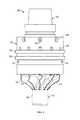
- FIG. 1is a side view of an ultrasonic machining module in accordance with an exemplary embodiment of the present invention
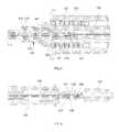
- FIG. 2is a cross-sectional view of the ultrasonic machining module of FIG. 1 ;
- FIG. 3is a side view of an ultrasonic machining module in accordance with an alternate embodiment of the present invention, wherein a high-speed rotary connector has been included on one end of a rotating spindle assembly that has been adapted to include a through spindle coolant system for delivering coolant fluid to a machining tool connected to the ultrasonic machining module;
- FIG. 4is a cross-sectional side view of the ultrasonic machining module and rotating spindle assembly of FIG. 4 ;
- FIG. 5is a cross-sectional side view of the ultrasonic machining module and rotating spindle assembly of FIG. 4 showing the portion of the rotating spindle assembly that includes the ultrasonic machining module;
- FIG. 6is a cross-sectional side view of the ultrasonic machining module and rotating spindle assembly of FIG. 4 showing the portion of the rotating spindle assembly that includes the electrical rotary connector;
- FIG. 7is a partial perspective view of a non-rotating embodiment of the present invention, wherein the ultrasonic module is mounted on a rigid turret that includes other machining tools;
- FIG. 8is a generalized schematic/flowchart of a closed-loop machining system that includes an ultrasonic machining module in communication with a processor that utilizes a safety and compatibility bridge to selectively power the ultrasonic machining module based on certain predetermined operational parameters.
- a first exemplary embodiment of the present inventionprovides an ultrasonic machining module for use in a machining system, wherein the ultrasonic machining module includes: (a) an ultrasonic transducer, wherein the ultrasonic transducer is adapted to receive a machining tool, and wherein the ultrasonic transducer further comprises: (i) a front mass; (ii) a back mass; (iii) a plurality of piezoelectric ceramics positioned between the front mass and back mass; (iv) at least electrical contact (e.g., an electrode) sandwiched between the piezoelectric ceramics; and (v) a compressive member (e.g.
- a boltpassing through the front mass, back mass, ceramics, and electrodes, wherein the compressive member is operative to apply compressive force to the ceramics; and (b) a vibration-isolating housing adapted to be both compatible with a machining system and to receive the ultrasonic transducer therein.
- the housingfurther includes a spring-like feature formed radially therein above the front mass, wherein the spring-like feature further includes a curved and thinned section of the housing, and wherein the curved and thinned section of the housing is operative to permit flexion in the housing for isolating all vibrations generated by the ultrasonic transducer when the device is in operation except axial vibrations transmitted to the machining tool, thereby preventing unwanted vibrations from traveling backward or upward into the machining system and potentially causing damage to the system or other problems.
- This particular embodimentis disclosed in U.S. patent application Ser. No. 13/046,099 (now U.S. Pat. No. 8,870,500), which is expressly incorporated by reference herein in its entirety, for all purposes.
- an exemplary embodiment of ultrasonic machining module 10includes three basic components: tool holder 20 , housing 40 , and ultrasonic transducer assembly 70 .
- Tool holder 20includes upper portion 22 , which further includes primary bore 24 formed therein for attaching machining module 10 to the main spindle (e.g., CAT 40 , 60 or HSK) of a machining system or center (not shown).
- Lower portion 26 of tool holder 20includes a plurality of secondary bores 28 that cooperate with similar structures in housing 40 to mechanically couple tool holder 20 to housing 40 using connectors 49 (i.e., centering bolts).
- connectors 49i.e., centering bolts
- tool holder 20is shrink-fit to housing 20 in addition to or instead of being bolted thereto.
- Housing 40includes a rigid cylindrical body 42 that further includes a centrally located aperture 44 that is adapted to receive tool holder 20 , and a bottom opening 54 , into which ultrasonic transducer assembly 70 is inserted.
- Circumferential electrical contacts 56i.e., slip rings
- a single contact 56may be utilized or the contacts may extend through the spindle of the machining system, while still providing or maintaining the flow of cooling air through the spindle.
- housing 40includes a plurality of apertures 46 that connect to a plurality of bores 48 that correspond to the placement of bores 28 in tool holder 20 when machining module 10 is assembled.
- a series of connectors 49are inserted into bores 48 and 28 for the purpose of bolting tool holder 20 to housing 40 .
- a plurality of air outlets 50is formed in housing 20 . As described in greater detail below, air outlets 50 cooperate with specific structures on ultrasonic transducer assembly 70 to cool machining module 10 when in use, thereby reducing or eliminating the need for any separate or external system or apparatus for cooling piezoelectric ceramics 74 .
- Housing 40also includes circumferential region 52 , which acts as a vibration isolating spring, and as such is characterized as a “spring-like structure”.
- region 52includes a contoured and thinned section of the material from which housing 40 is manufactured. When machining module 10 is in use, region 52 permits a degree of flexion in housing 40 , thereby absorbing and/or isolating acoustic energy generated by ultrasonic transducer assembly 70 and preventing unwanted vibration from traveling backward or upward into the spindle or other mechanical components of the machining system.
- Axial vibration generated by ultrasonic transducer assembly 70is not diminished by region 52 ; therefore, torque is still delivered to the machining tool or other item that is attached to front mass 76 and that is being used to machine a workpiece.
- machining toolshould be understood to mean drill bit or any other machining tool or item that is attached to front mass 76 .
- region 52is operative to absorb and/or isolate most or all vibrational modes except the axial vibrations directed toward the workpiece.
- Ultrasonic transducer assembly 70includes back mass 72 , front mass 76 , and a plurality of piezoelectric ceramics 74 positioned between these two structures. A plurality of electrodes 75 are sandwiched between piezoelectric ceramics 74 , and compressive member 86 passes through back mass 72 , ceramics 74 , electrodes 75 and a portion of front mass 76 . When tightened, compressive member 86 is operative to apply compressive force to piezoelectric ceramics 74 .
- a series of electrical lead wiresare typically attached to at least one of the electrodes 75 . These wires exit the interior of housing 40 either through housing 40 or through tool holder 20 where they then connect to circumferential electrical contacts 56 . Brush contacts or other types of electrical contacts may be used to provide electricity to machining module 10 . Transducer assembly 70 typically operates at power levels ranging from 1 kW-5 kW and amplitudes ranging from 25 ⁇ m to 150 ⁇ m.
- ultrasonic transducer assembly 70further includes a plurality of cooling members, fins or vanes 78 that are located circumferentially around front mass 76 just beneath a plurality of air inlets 80 that are also formed in front mass 76 .
- vanes 78which simulate a compressor wheel, are operative to draw air upward and through air inlets 80 . Air then flows through the interior of housing 40 across ceramics 74 for cooling purposes, and exits housing 40 though air outlets 50 .
- the front or bottom area of front mass 76includes a tapered collet 82 that further includes bore 84 , which is adapted to receive a drill bit, milling tool, or other item.
- a drill bit or other itemmay be attached to collet 82 using the process known as shrink-fitting.
- shrink-fittingBy heating the mass around bore 84 uniformly, it is possible to significantly expand the diameter of the bore. The shaft of a drill bit or other item is then inserted into the expanded bore. Upon cooling, the mass around the bore shrinks back to its original diameter and frictional forces create a highly effective joint.
- the bottom edge of housing 40is attached to the top portion of front mass 76 using a shrink-fit process for facilitating removal of case 40 for repairing ultrasonic machining module 10 .
- a shrink-fit processfor facilitating removal of case 40 for repairing ultrasonic machining module 10 .
- ultrasonic machining module 10Some or all of the metal components of ultrasonic machining module 10 are typically manufactured from A2 tool steel. Alternately, D2, SS, 4140, and/or 350-M tool steel may be used. Regardless of the material used, front mass 76 and back mass 72 may both be manufactured from the same material as a means for reducing amplitude. In general terms, mixing of the mass of these components adjusts amplitude. In the exemplary embodiment shown in FIGS. 1-2 , total module length is about 7.5 inches (19.1 cm). However, the present invention is scalable and miniaturized variants of ultrasonic machining module 10 are compatible with medical and surgical systems and devices, among other applications.
- some embodiments of the present inventionalso includes features that permit the introduction of the high-voltage signals that are used to operate high-power ultrasonic systems within a machining or metalworking environment.
- this inventionis capable of transmitting voltages over 400 VAC at power levels up to 10 kW through, for example, the use of a high-speed rotary electrical connector that is connected to an appropriate power supply (see FIG. 8 ).
- FIG. 8illustrates a high-speed rotary electrical connector that is connected to an appropriate power supply.
- FIG. 3provides a side view of an alternate embodiment of the present invention, wherein a high-speed rotary electrical connector has been included on one end of a rotating spindle assembly 100 that has been adapted to include a through-spindle coolant system for delivering coolant fluid to a machining tool (e.g., a drill bit) attached to ultrasonic machining module 110 .
- rotating spindle assembly 100includes ultrasonic machining module 110 , collet 114 (which is adapted to receive machining tools), bearing housing 130 , drive shaft 140 , coolant adapter 142 , rotary slip ring 144 , alignment ring 146 , and coolant rotary union 150 .
- FIG. 4provides a detailed cross-sectional side view of rotating spindle assembly 100 , wherein the following components are depicted in their relative positions within rotating spindle assembly 100 : ultrasonic module 110 , ultrasonic transducer 112 , collet 114 , housing 116 , tool support or tool holder 120 , retention knob 122 , bearing housing 130 , bearing 132 , electrical connection 134 , electrode shaft 136 , drive shaft 140 , coolant adapter 142 , rotary slip ring 144 , alignment ring 146 , and coolant rotary union 150 .
- FIG. 5provides a cross-sectional side view of the portion of rotating spindle assembly 100 that includes ultrasonic machining module 110 and depicts the following additional structures: vibration dampening feature 118 , transducer coolant coupler 124 , electrical connection 134 , electrode shaft 136 , and coolant plug 138 .
- FIG. 6provides a cross-sectional side view of the portion of rotating spindle assembly 100 that includes coolant rotary union 150 and depicts the following additional structures: electrode path 137 and coolant electrode seal 154 .
- electrical energyis delivered to ultrasonic transducer 112 using conductors that are located in a central lengthwise passage (electrode shaft 136 ) formed in rotating spindle assembly 100 . These conductors run parallel through rotating spindle assembly 100 and make electrical contact with electrodes located within retention knob 122 (which also positions tool holder 120 within housing 116 ) at electrical connection 134 , wherein electrical connection 134 is typically a two conductor pin connection. Electrical connection 134 also includes a plug and stem; wherein plug 138 makes the electrical connection and the stem protrudes into the body of retention knob 122 for sealing the electrical components from coolant fluid passing through fluid conduit 135 .
- Electrode shaft 136includes a stainless steel inner sleeve for withstanding high pressure situations that develop within rotating spindle assembly 100 during operations that include coolant fluid. For this connection to function with various tool changers, both positive and negative electrodes float in a manner that can be compressed with a plunger device during tool changing events. Electrical energy is delivered by high voltage rotary slip ring 144 , which is mounted on rotating spindle assembly 100 on the end thereof that is opposite ultrasonic machining module 110 . Rotary slip ring 144 exposes positive and negative electrode wiring through wiring passages 137 , thereby permitting electrical connection to a processor main cable.
- FIG. 7provides a partial perspective view of a non-rotating embodiment 200 of the present invention, wherein an ultrasonic machining module 210 (which is similar to ultrasonic machining module 110 ) is mounted on a rigid turret 205 that includes other machining tools 250 , 260 , and 270 .
- a non-rotating retention assemblyreplaces the rotating spindle assembly and a supportive tool post (not shown in the Figures) replaces tool holder 120 .
- This embodimentmay also include a through-transducer coolant pathway for delivering coolant fluid to the machining tool.
- FIG. 8provides a generalized schematic/flowchart of a closed-loop machining center or system 310 that includes an ultrasonic machining module 316 in communication with a processor 314 that utilizes a safety and compatibility bridge 320 to selectively power ultrasonic machining module 316 based on certain predetermined operational parameters.
- machining center 312is in communication with processor 314 , which communicates with a microprocessor located in, on, or associated with ultrasonic machining module 316 for the purpose of verifying the presence of module 316 and for verifying other important aspects of ultrasonic machining module 316 with regard to compatibility with, and proper operation of, machining center 312 .
- Processor 314gathers data regarding ultrasonic machining module 316 at process step 318 and safety and compatibility bridge 320 analyzes this data at process step 322 . Any necessary or required correction of the setup, communications, or operational parameters (or any other aspects of system 310 ) occurs at process step 324 .
- safety and compatibility bridge 320prevents power supply 330 from providing power to ultrasonic machining module 316 (through any associated spindle or retention assembly) and machining center 312 will not operate. If no unsafe, unacceptable, or uncorrectable conditions are detected during analysis 322 , safety and compatibility bridge 320 permits the powering of ultrasonic machining module 316 by power supply 330 at process step 328 and ultrasonic machining module 316 performs the desired operations on workpiece 332 .
- machining system 310utilizes processor 314 , which communicates (wirelessly or otherwise) with a microprocessor (e.g., an identification chip) 319 mounted on or in or otherwise associated with ultrasonic machining module 310 .
- microprocessor 319communicates amplitude range of module 310 based on predetermined power settings for machining system 310 .
- Microprocessor 319which may be radio-frequency based in some embodiments, also communicates acceptable electrical connection conditions with power supply 330 and determines that no shorting events have occurred or are occurring. With regard to safety, it is important that the functional characteristics of ultrasonic machining module 310 be monitored at each predetermined power setting.
- Microprocessor 319also communicates that an uninterrupted signal has been established with processor 314 .
- Safety and compatibility bridge 320confirms connection with an appropriate ultrasonic machining module 310 and will not allow power to be delivered to a spindle or retention assembly without an ultrasonic module connected to machining system 310 .
- safety and compatibility bridge 230confirms that the ultrasonic module has been installed in the correct orientation, i.e., positive-to-positive and negative-to-negative.
- safety and compatibility bridge 320also identifies coolant contamination that could lead to electrical energy being distributed through a machine tool into workpiece 332 , and/or an operator of machining system 310 .
- Processor 314provides numerous advanced features and includes software for providing microprocessor 319 with safety instructions based on predetermined operational parameters for ultrasonic machining module 310 .
- Conventional practice in the field of ultrasonicstypically utilizes a power supply that controls system operations. For example, a power supply auto tunes to a resonant frequency of a machining system and locks onto drive at a programmed amplitude setting. The machining process is typically controlled by monitoring time, power, distance, etc. This is usually accomplished with power supplies that have a frequency bandwidth of ⁇ 500 Hz and as much as ⁇ 1 kHz.
- processor 314includes communication (typically wireless) with devices that are connected to main power supply 330 for identifying a correct ultrasonic machining module, ensuring safe operating conditions, and communicating to processor 314 within what amplitude domain the ultrasonic machining module should be operating.
- processor 314executes a frequency scan between 15 kHz and 25 kHz, and during this scan, processor 314 measures the impedance of the ultrasonic transducer within ultrasonic machining module 316 at varying frequencies to identify all resonant frequencies within that range.
- Processor 314then establishes the longitudinal resonance of ultrasonic machining module 316 by monitoring system Q (i.e., reactive power/volt-ampere reactive), power at resonance, and capacitance.
- monitoring system Qi.e., reactive power/volt-ampere reactive
- processor 314communicates with machining center 312 to identify the RPM, feed rate, and tool diameter being used in a selected program. Processor 314 then uses a velocity algorithm to calculate the magnitude of machining velocity and calculates what the magnitude of velocity should be to correctly fit with predetermined machining parameters. This calculation results in an amplitude based on the resonant frequency established by processor 314 during the identification phase. Processor 314 also determines if a solid tool (i.e., drill bit) has been broken during machining operations. In the event of tool breakage, the impedance and frequency of ultrasonic machining module 310 will detect a sharp and sudden shift upon failure. In this event, a fault condition will arise and processor 314 will induce a soft stop condition on the machining tool followed with an error message.
- a solid tooli.e., drill bit
- processor 314includes: (i) utilization of at least one algorithm to calculate at least one desired ultrasonic amplitude for ultrasonic machining module 316 ; (ii) providing fault status identification in the form of overloading, tool breakage, or a combination thereof; (iii) providing auto-tuning capability for identifying at least one desired resonant mode for ultrasonic machining module 316 ; and (iv) communication with microprocessor 319 to disable ultrasonic machining module 316 and place system 310 in a soft-stop condition, when necessary.
- safety and compatibility bridge 320include: (i) enabling communication between processor 314 and ultrasonic machining module 316 for purposes of identifying the ultrasonic machining module connected to machining center 312 and verifying its compatibility therewith; (ii) enabling communication between processor 314 and ultrasonic machining module 316 for confirming correct electrical contact, short circuit monitoring, or a combination thereof; (iii) enabling monitoring of the electrical connections for proper polarity; (iv) enabling monitoring of system 310 for the presence or absence of an ultrasonic machining module; (v) enabling monitoring of system 310 for a short-circuit condition caused by foreign object debris, electrical contaminants, or a combination thereof; and (vi) disabling the delivery of electrical power if an ultrasonic machining module is not connected to machining center 312 .
Landscapes
- Engineering & Computer Science (AREA)
- Mechanical Engineering (AREA)
- Turning (AREA)
Abstract
Description
Claims (33)
Priority Applications (2)
| Application Number | Priority Date | Filing Date | Title |
|---|---|---|---|
| PCT/US2015/049676WO2017039709A1 (en) | 2015-09-04 | 2015-09-11 | Closed-loop metalworking system |
| US14/851,654US9764390B2 (en) | 2015-09-04 | 2015-09-11 | Closed-loop metalworking system |
Applications Claiming Priority (2)
| Application Number | Priority Date | Filing Date | Title |
|---|---|---|---|
| US14/846,064US9878377B2 (en) | 2010-03-11 | 2015-09-04 | High-speed rotary electrical connector for use in ultrasonically assisted machining |
| US14/851,654US9764390B2 (en) | 2015-09-04 | 2015-09-11 | Closed-loop metalworking system |
Related Parent Applications (1)
| Application Number | Title | Priority Date | Filing Date |
|---|---|---|---|
| US14/846,064Continuation-In-PartUS9878377B2 (en) | 2010-03-11 | 2015-09-04 | High-speed rotary electrical connector for use in ultrasonically assisted machining |
Publications (2)
| Publication Number | Publication Date |
|---|---|
| US20170066061A1 US20170066061A1 (en) | 2017-03-09 |
| US9764390B2true US9764390B2 (en) | 2017-09-19 |
Family
ID=58189502
Family Applications (1)
| Application Number | Title | Priority Date | Filing Date |
|---|---|---|---|
| US14/851,654Active2035-12-30US9764390B2 (en) | 2015-09-04 | 2015-09-11 | Closed-loop metalworking system |
Country Status (2)
| Country | Link |
|---|---|
| US (1) | US9764390B2 (en) |
| WO (1) | WO2017039709A1 (en) |
Cited By (1)
| Publication number | Priority date | Publication date | Assignee | Title |
|---|---|---|---|---|
| US20180113033A1 (en)* | 2015-04-30 | 2018-04-26 | Kistler Holding Ag | Contact force testing apparatus, use of such a contact force testing apparatus and method for producing such a contact force testing apparatus |
Families Citing this family (2)
| Publication number | Priority date | Publication date | Assignee | Title |
|---|---|---|---|---|
| DE102017122511B3 (en) | 2017-09-27 | 2018-11-22 | SCHOTT Diamantwerkzeuge GmbH | Cooling system for an ultrasonic hand drill, ultrasonic hand drill and method for cooling a vibration exciter unit of an ultrasonic hand drill |
| CN111480345B (en)* | 2017-12-14 | 2022-04-29 | 弗洛设计声能学公司 | Acoustophoretic system, method for operating acoustophoretic system, and method for controlling acoustic transducer and acoustic system |
Citations (51)
| Publication number | Priority date | Publication date | Assignee | Title |
|---|---|---|---|---|
| US3561462A (en)* | 1969-10-10 | 1971-02-09 | Branson Instr | Ultrasonic drive assembly for machine tool |
| US3614484A (en)* | 1970-03-25 | 1971-10-19 | Branson Instr | Ultrasonic motion adapter for a machine tool |
| US4649609A (en)* | 1983-12-30 | 1987-03-17 | Westinghouse Electric Corp. | Apparatus and process for providing an alternate coolant path in the core of a nuclear reactor |
| US5140773A (en)* | 1990-02-14 | 1992-08-25 | Brother Kogyo Kabushiki Kaisha | Ultrasonic machine and its machining method |
| US5357423A (en)* | 1993-02-22 | 1994-10-18 | Kulicke And Soffa Investments, Inc. | Apparatus and method for automatically adjusting power output of an ultrasonic generator |
| US5842149A (en) | 1996-10-22 | 1998-11-24 | Baker Hughes Incorporated | Closed loop drilling system |
| US20010020808A1 (en)* | 2000-02-24 | 2001-09-13 | Hideyuki Suzuki | Torsional vibrating apparatus for ultrasonic machining |
| US6289736B1 (en)* | 1997-03-27 | 2001-09-18 | Uit, L.L.C. Company | Means and method for electroacoustic transducer excitation |
| US20020019683A1 (en)* | 2000-03-23 | 2002-02-14 | Dawn White | Ultrasonic object consolidation system and method |
| US20020049427A1 (en)* | 2000-10-20 | 2002-04-25 | Ethicon Endo-Surgery, Inc. | Method for detecting blade breakage using rate and/or impedance information |
| US20020057541A1 (en)* | 2000-10-20 | 2002-05-16 | Ethicon Endo-Surgery, Inc. | Detection circuitry for surgical handpiece system |
| US6519500B1 (en)* | 1999-09-16 | 2003-02-11 | Solidica, Inc. | Ultrasonic object consolidation |
| US20030079557A1 (en)* | 2001-10-31 | 2003-05-01 | Tatum Gary Allen | Boltless ultrasonic flowmeter transducer mount |
| US20030226887A1 (en)* | 2002-06-06 | 2003-12-11 | Tsuyoshi Komine | Information system and information-holding unit |
| US6762535B2 (en)* | 2001-11-07 | 2004-07-13 | Takesho Co., Ltd. | Spindle structure in ultrasonic machine and supporting horn used in the same |
| US20040180769A1 (en)* | 2003-03-12 | 2004-09-16 | Dwayne Perry | Tool side robotic safety interlock |
| US20050021021A1 (en)* | 2003-05-28 | 2005-01-27 | Foltz James W. | Electrical cautery-oxygen safety device |
| US20050065647A1 (en)* | 2003-08-25 | 2005-03-24 | Dwayne Perry | Robotic tool coupler rapid-connect bus |
| US7137185B2 (en)* | 2003-12-09 | 2006-11-21 | Bilz Werkzeugfabrik Gmbh & Co. Kg | Tool holder for shrink-fit attachment of rotating tools with predominantly cylindrical shafts |
| US20070155349A1 (en)* | 2005-12-29 | 2007-07-05 | Nelson Mark E | Systems and methods for selectively controlling electrical outlets using power profiling |
| US20070163349A1 (en)* | 2005-12-29 | 2007-07-19 | Dukane Corporation | Systems for providing controlled power to ultrasonic welding probes |
| US7297238B2 (en)* | 2003-03-31 | 2007-11-20 | 3M Innovative Properties Company | Ultrasonic energy system and method including a ceramic horn |
| US20080041604A1 (en)* | 2004-07-02 | 2008-02-21 | Hermann Sauer | Tool with an Oscillating Head |
| US20080173145A1 (en)* | 2007-01-19 | 2008-07-24 | Hsi-Kuan Chen | Tool device for a processing machine |
| US7431779B2 (en)* | 1998-09-03 | 2008-10-07 | U.I.T., L.L.C. | Ultrasonic impact machining of body surfaces to correct defects and strengthen work surfaces |
| US20090035087A1 (en)* | 2005-09-09 | 2009-02-05 | Kazuo Nakamoto | Machine tool |
| US20090198369A1 (en)* | 2008-02-05 | 2009-08-06 | The Boeing Company | Adaptive control of composite plycutting |
| US20090224703A1 (en)* | 2005-10-12 | 2009-09-10 | Black & Decker Inc. | Control and Protection Methodologies For A Motor Control Module |
| US20100125388A1 (en)* | 2008-11-18 | 2010-05-20 | Denso Corporation | Information writing tool and system |
| US20100140326A1 (en)* | 2008-12-08 | 2010-06-10 | Panasonic Corporation | Bonding tool, electronic component mounting apparatus and electronic component mounting method |
| US20100154161A1 (en)* | 2006-01-20 | 2010-06-24 | Kumio Takahashi | Dust collector |
| US20110126685A1 (en)* | 2009-11-30 | 2011-06-02 | Manfred Geiss | Device for ultrasonic machining, machine tool and machine tool apparatus |
| US20110155407A1 (en)* | 2009-12-31 | 2011-06-30 | Metal Industries Research&Development Centre | Modularized ultrasonic vibration machining apparatus |
| US20110222975A1 (en)* | 2010-03-11 | 2011-09-15 | Edison Welding Institute, Inc. | Ultrasonic machining module |
| US20110268516A1 (en)* | 2010-04-29 | 2011-11-03 | Edison Welding Institute, Inc. | Ultrasonic machining assembly for use with portable devices |
| US20120277928A1 (en)* | 2010-10-22 | 2012-11-01 | Siemens Aktiengesellschaft | Device and method for reducing the energy consumption of a machine in the field of automation engineering |
| WO2013093845A1 (en) | 2011-12-22 | 2013-06-27 | Sintesi Development S.R.L. | Machining mechatronic system and command group of the mechatronic system |
| US20140088753A1 (en)* | 2011-06-02 | 2014-03-27 | Black & Decker Inc. | Control system for a fastening power tool |
| US8875804B2 (en)* | 2010-01-07 | 2014-11-04 | Black & Decker Inc. | Screwdriving tool having a driving tool with a removable contact trip assembly |
| US20150051728A1 (en)* | 2013-08-14 | 2015-02-19 | Korea Tool Monitoring Co., Ltd. | Detecting method of abnormality of machine tool operation |
| US20150105874A1 (en)* | 2013-10-16 | 2015-04-16 | Fanuc Corporation | Numerical control device acquiring alarm information from connected io unit |
| US20150127137A1 (en)* | 2012-04-04 | 2015-05-07 | Hypertherm, Inc. | Identifying Components in a Material Processing System |
| US20150151447A1 (en)* | 2012-06-12 | 2015-06-04 | Husqvarna Ab | Electric cutting system |
| US20150253757A1 (en)* | 2014-03-07 | 2015-09-10 | Fanuc Corporation | Robot controller for controlling robot which supplies and discharges workpiece |
| US20150265358A1 (en)* | 2012-08-03 | 2015-09-24 | Stryker Corporation | Robotic System and Method for Transitioning Between Operating Modes |
| US20150265347A1 (en)* | 2014-03-18 | 2015-09-24 | Ethicon Endo-Surgery, Inc. | Detecting short circuits in electrosurgical medical devices |
| US20150300165A1 (en)* | 2015-07-06 | 2015-10-22 | Caterpillar Paving Products Inc. | Rotary cutter system for machines |
| US9283045B2 (en)* | 2012-06-29 | 2016-03-15 | Ethicon Endo-Surgery, Llc | Surgical instruments with fluid management system |
| US20160124416A1 (en)* | 2014-11-03 | 2016-05-05 | Mikron Agie Charmilles SA | Standby control for machine tools |
| US20160342151A1 (en)* | 2015-05-18 | 2016-11-24 | Milwaukee Electric Tool Corporation | User interface for tool configuration and data capture |
| US20170020613A1 (en)* | 2006-05-19 | 2017-01-26 | Mako Surgical Corp. | Method and apparatus for controlling a haptic device |
- 2015
- 2015-09-11USUS14/851,654patent/US9764390B2/enactiveActive
- 2015-09-11WOPCT/US2015/049676patent/WO2017039709A1/ennot_activeCeased
Patent Citations (54)
| Publication number | Priority date | Publication date | Assignee | Title |
|---|---|---|---|---|
| US3561462A (en)* | 1969-10-10 | 1971-02-09 | Branson Instr | Ultrasonic drive assembly for machine tool |
| US3614484A (en)* | 1970-03-25 | 1971-10-19 | Branson Instr | Ultrasonic motion adapter for a machine tool |
| US4649609A (en)* | 1983-12-30 | 1987-03-17 | Westinghouse Electric Corp. | Apparatus and process for providing an alternate coolant path in the core of a nuclear reactor |
| US5140773A (en)* | 1990-02-14 | 1992-08-25 | Brother Kogyo Kabushiki Kaisha | Ultrasonic machine and its machining method |
| US5357423A (en)* | 1993-02-22 | 1994-10-18 | Kulicke And Soffa Investments, Inc. | Apparatus and method for automatically adjusting power output of an ultrasonic generator |
| US5842149A (en) | 1996-10-22 | 1998-11-24 | Baker Hughes Incorporated | Closed loop drilling system |
| US6289736B1 (en)* | 1997-03-27 | 2001-09-18 | Uit, L.L.C. Company | Means and method for electroacoustic transducer excitation |
| US7431779B2 (en)* | 1998-09-03 | 2008-10-07 | U.I.T., L.L.C. | Ultrasonic impact machining of body surfaces to correct defects and strengthen work surfaces |
| US6519500B1 (en)* | 1999-09-16 | 2003-02-11 | Solidica, Inc. | Ultrasonic object consolidation |
| US20010020808A1 (en)* | 2000-02-24 | 2001-09-13 | Hideyuki Suzuki | Torsional vibrating apparatus for ultrasonic machining |
| US20020019683A1 (en)* | 2000-03-23 | 2002-02-14 | Dawn White | Ultrasonic object consolidation system and method |
| US20020057541A1 (en)* | 2000-10-20 | 2002-05-16 | Ethicon Endo-Surgery, Inc. | Detection circuitry for surgical handpiece system |
| US20020049427A1 (en)* | 2000-10-20 | 2002-04-25 | Ethicon Endo-Surgery, Inc. | Method for detecting blade breakage using rate and/or impedance information |
| US6633234B2 (en)* | 2000-10-20 | 2003-10-14 | Ethicon Endo-Surgery, Inc. | Method for detecting blade breakage using rate and/or impedance information |
| US20030079557A1 (en)* | 2001-10-31 | 2003-05-01 | Tatum Gary Allen | Boltless ultrasonic flowmeter transducer mount |
| US6762535B2 (en)* | 2001-11-07 | 2004-07-13 | Takesho Co., Ltd. | Spindle structure in ultrasonic machine and supporting horn used in the same |
| US20030226887A1 (en)* | 2002-06-06 | 2003-12-11 | Tsuyoshi Komine | Information system and information-holding unit |
| US20040180769A1 (en)* | 2003-03-12 | 2004-09-16 | Dwayne Perry | Tool side robotic safety interlock |
| US7297238B2 (en)* | 2003-03-31 | 2007-11-20 | 3M Innovative Properties Company | Ultrasonic energy system and method including a ceramic horn |
| US20050021021A1 (en)* | 2003-05-28 | 2005-01-27 | Foltz James W. | Electrical cautery-oxygen safety device |
| US20050065647A1 (en)* | 2003-08-25 | 2005-03-24 | Dwayne Perry | Robotic tool coupler rapid-connect bus |
| US7027893B2 (en)* | 2003-08-25 | 2006-04-11 | Ati Industrial Automation, Inc. | Robotic tool coupler rapid-connect bus |
| US7137185B2 (en)* | 2003-12-09 | 2006-11-21 | Bilz Werkzeugfabrik Gmbh & Co. Kg | Tool holder for shrink-fit attachment of rotating tools with predominantly cylindrical shafts |
| US20080041604A1 (en)* | 2004-07-02 | 2008-02-21 | Hermann Sauer | Tool with an Oscillating Head |
| US20090035087A1 (en)* | 2005-09-09 | 2009-02-05 | Kazuo Nakamoto | Machine tool |
| US20090224703A1 (en)* | 2005-10-12 | 2009-09-10 | Black & Decker Inc. | Control and Protection Methodologies For A Motor Control Module |
| US7475801B2 (en)* | 2005-12-29 | 2009-01-13 | Dukane Corporation | Systems for providing controlled power to ultrasonic welding probes |
| US20070155349A1 (en)* | 2005-12-29 | 2007-07-05 | Nelson Mark E | Systems and methods for selectively controlling electrical outlets using power profiling |
| US20070163349A1 (en)* | 2005-12-29 | 2007-07-19 | Dukane Corporation | Systems for providing controlled power to ultrasonic welding probes |
| US20100154161A1 (en)* | 2006-01-20 | 2010-06-24 | Kumio Takahashi | Dust collector |
| US20170020613A1 (en)* | 2006-05-19 | 2017-01-26 | Mako Surgical Corp. | Method and apparatus for controlling a haptic device |
| US20080173145A1 (en)* | 2007-01-19 | 2008-07-24 | Hsi-Kuan Chen | Tool device for a processing machine |
| US20090198369A1 (en)* | 2008-02-05 | 2009-08-06 | The Boeing Company | Adaptive control of composite plycutting |
| US20100125388A1 (en)* | 2008-11-18 | 2010-05-20 | Denso Corporation | Information writing tool and system |
| US20100140326A1 (en)* | 2008-12-08 | 2010-06-10 | Panasonic Corporation | Bonding tool, electronic component mounting apparatus and electronic component mounting method |
| US20110126685A1 (en)* | 2009-11-30 | 2011-06-02 | Manfred Geiss | Device for ultrasonic machining, machine tool and machine tool apparatus |
| US20110155407A1 (en)* | 2009-12-31 | 2011-06-30 | Metal Industries Research&Development Centre | Modularized ultrasonic vibration machining apparatus |
| US8875804B2 (en)* | 2010-01-07 | 2014-11-04 | Black & Decker Inc. | Screwdriving tool having a driving tool with a removable contact trip assembly |
| US20110222975A1 (en)* | 2010-03-11 | 2011-09-15 | Edison Welding Institute, Inc. | Ultrasonic machining module |
| US20110268516A1 (en)* | 2010-04-29 | 2011-11-03 | Edison Welding Institute, Inc. | Ultrasonic machining assembly for use with portable devices |
| US20120277928A1 (en)* | 2010-10-22 | 2012-11-01 | Siemens Aktiengesellschaft | Device and method for reducing the energy consumption of a machine in the field of automation engineering |
| US20140088753A1 (en)* | 2011-06-02 | 2014-03-27 | Black & Decker Inc. | Control system for a fastening power tool |
| WO2013093845A1 (en) | 2011-12-22 | 2013-06-27 | Sintesi Development S.R.L. | Machining mechatronic system and command group of the mechatronic system |
| US20150127137A1 (en)* | 2012-04-04 | 2015-05-07 | Hypertherm, Inc. | Identifying Components in a Material Processing System |
| US20150151447A1 (en)* | 2012-06-12 | 2015-06-04 | Husqvarna Ab | Electric cutting system |
| US9283045B2 (en)* | 2012-06-29 | 2016-03-15 | Ethicon Endo-Surgery, Llc | Surgical instruments with fluid management system |
| US20150265358A1 (en)* | 2012-08-03 | 2015-09-24 | Stryker Corporation | Robotic System and Method for Transitioning Between Operating Modes |
| US20150051728A1 (en)* | 2013-08-14 | 2015-02-19 | Korea Tool Monitoring Co., Ltd. | Detecting method of abnormality of machine tool operation |
| US20150105874A1 (en)* | 2013-10-16 | 2015-04-16 | Fanuc Corporation | Numerical control device acquiring alarm information from connected io unit |
| US20150253757A1 (en)* | 2014-03-07 | 2015-09-10 | Fanuc Corporation | Robot controller for controlling robot which supplies and discharges workpiece |
| US20150265347A1 (en)* | 2014-03-18 | 2015-09-24 | Ethicon Endo-Surgery, Inc. | Detecting short circuits in electrosurgical medical devices |
| US20160124416A1 (en)* | 2014-11-03 | 2016-05-05 | Mikron Agie Charmilles SA | Standby control for machine tools |
| US20160342151A1 (en)* | 2015-05-18 | 2016-11-24 | Milwaukee Electric Tool Corporation | User interface for tool configuration and data capture |
| US20150300165A1 (en)* | 2015-07-06 | 2015-10-22 | Caterpillar Paving Products Inc. | Rotary cutter system for machines |
Non-Patent Citations (2)
| Title |
|---|
| International Search Report, Mail Date: Dec. 28, 2015; International Application No. PCT/US15/49676, filed Sep. 11, 2015. |
| Office Action, U.S. Appl. No. 13/046,099, Sep. 23, 2013.* |
Cited By (2)
| Publication number | Priority date | Publication date | Assignee | Title |
|---|---|---|---|---|
| US20180113033A1 (en)* | 2015-04-30 | 2018-04-26 | Kistler Holding Ag | Contact force testing apparatus, use of such a contact force testing apparatus and method for producing such a contact force testing apparatus |
| US10753810B2 (en)* | 2015-04-30 | 2020-08-25 | Kistler Holding, Ag | Contact force testing apparatus, use of such a contact force testing apparatus and method for producing such a contact force testing apparatus |
Also Published As
| Publication number | Publication date |
|---|---|
| WO2017039709A1 (en) | 2017-03-09 |
| US20170066061A1 (en) | 2017-03-09 |
Similar Documents
| Publication | Publication Date | Title |
|---|---|---|
| CA2962583C (en) | Closed-loop metalworking system | |
| EP2548298B1 (en) | Ultrasonic machining module | |
| KR101521075B1 (en) | Ultrasonic machining assembly for use with portable devices | |
| CA2959406C (en) | Tool attachment and through spindle coolant systems for use with ultrasonic machining modules | |
| US9782835B2 (en) | Tool attachment and through spindle coolant systems for use with ultrasonic machining modules | |
| KR102417763B1 (en) | High-speed rotary electrical connector for use in ultrasonically assisted machining | |
| JP6389324B2 (en) | Device for isolating acoustic vibrations in metal processing systems | |
| US9764390B2 (en) | Closed-loop metalworking system | |
| JP2005224865A (en) | Ultrasonic spindle working machine and tip unit used for the same | |
| US9669471B2 (en) | Devices for isolating acoustic vibrations in metalworking systems |
Legal Events
| Date | Code | Title | Description |
|---|---|---|---|
| AS | Assignment | Owner name:EDISON INDUSTRIAL INNOVATION, LLC, OHIO Free format text:ASSIGNMENT OF ASSIGNORS INTEREST;ASSIGNOR:SHORT, MATTHEW A.;REEL/FRAME:036564/0575 Effective date:20150911 | |
| AS | Assignment | Owner name:CUMBERLAND & WESTERN RESOURCES, LLC, KENTUCKY Free format text:SECURITY INTEREST;ASSIGNORS:EDISON INDUSTRIAL INNOVATION, LLC;ACOUSTECH SYSTEMS, LLC;REEL/FRAME:038269/0091 Effective date:20160401 | |
| AS | Assignment | Owner name:CUMBERLAND & WESTERN RESOURCES, LLC, KENTUCKY Free format text:SECURITY INTEREST;ASSIGNORS:EDISON INDUSTRIAL INNOVATIONS, LLC;ACOUSTECH SYSTEMS, LLC;REEL/FRAME:041572/0045 Effective date:20170201 | |
| AS | Assignment | Owner name:CUMBERLAND & WESTERN RESOURCES, LLC, KENTUCKY Free format text:CORRECTIVE ASSIGNMENT TO CORRECT THE FIRST ASSIGNOR'S NAME PREVIOUSLY RECORDED AT REEL: 041572 FRAME: 0045. ASSIGNOR(S) HEREBY CONFIRMS THE ASSIGNMENT;ASSIGNORS:EDISON INDUSTRIAL INNOVATION, LLC;ACOUSTECH SYSTEMS, LLC;REEL/FRAME:042113/0405 Effective date:20170201 | |
| STCF | Information on status: patent grant | Free format text:PATENTED CASE | |
| AS | Assignment | Owner name:EDISON INDUSTRIAL INNOVATION, LLC, KENTUCKY Free format text:ASSIGNMENT OF ASSIGNORS INTEREST;ASSIGNOR:EDISON WELDING INSTITUTE, INC.;REEL/FRAME:044221/0681 Effective date:20171018 | |
| MAFP | Maintenance fee payment | Free format text:PAYMENT OF MAINTENANCE FEE, 4TH YR, SMALL ENTITY (ORIGINAL EVENT CODE: M2551); ENTITY STATUS OF PATENT OWNER: SMALL ENTITY Year of fee payment:4 | |
| MAFP | Maintenance fee payment | Free format text:PAYMENT OF MAINTENANCE FEE, 8TH YR, SMALL ENTITY (ORIGINAL EVENT CODE: M2552); ENTITY STATUS OF PATENT OWNER: SMALL ENTITY Year of fee payment:8 |