US9764117B2 - Access device - Google Patents
Access deviceDownload PDFInfo
- Publication number
- US9764117B2 US9764117B2US14/543,576US201414543576AUS9764117B2US 9764117 B2US9764117 B2US 9764117B2US 201414543576 AUS201414543576 AUS 201414543576AUS 9764117 B2US9764117 B2US 9764117B2
- Authority
- US
- United States
- Prior art keywords
- needle
- dilator
- hub
- access device
- track
- Prior art date
- Legal status (The legal status is an assumption and is not a legal conclusion. Google has not performed a legal analysis and makes no representation as to the accuracy of the status listed.)
- Active, expires
Links
Images


Classifications
- A—HUMAN NECESSITIES
- A61—MEDICAL OR VETERINARY SCIENCE; HYGIENE
- A61M—DEVICES FOR INTRODUCING MEDIA INTO, OR ONTO, THE BODY; DEVICES FOR TRANSDUCING BODY MEDIA OR FOR TAKING MEDIA FROM THE BODY; DEVICES FOR PRODUCING OR ENDING SLEEP OR STUPOR
- A61M25/00—Catheters; Hollow probes
- A61M25/01—Introducing, guiding, advancing, emplacing or holding catheters
- A61M25/06—Body-piercing guide needles or the like
- A61M25/0606—"Over-the-needle" catheter assemblies, e.g. I.V. catheters
- A—HUMAN NECESSITIES
- A61—MEDICAL OR VETERINARY SCIENCE; HYGIENE
- A61B—DIAGNOSIS; SURGERY; IDENTIFICATION
- A61B17/00—Surgical instruments, devices or methods
- A61B17/34—Trocars; Puncturing needles
- A61B17/3415—Trocars; Puncturing needles for introducing tubes or catheters, e.g. gastrostomy tubes, drain catheters
- A—HUMAN NECESSITIES
- A61—MEDICAL OR VETERINARY SCIENCE; HYGIENE
- A61M—DEVICES FOR INTRODUCING MEDIA INTO, OR ONTO, THE BODY; DEVICES FOR TRANSDUCING BODY MEDIA OR FOR TAKING MEDIA FROM THE BODY; DEVICES FOR PRODUCING OR ENDING SLEEP OR STUPOR
- A61M25/00—Catheters; Hollow probes
- A61M25/01—Introducing, guiding, advancing, emplacing or holding catheters
- A61M25/06—Body-piercing guide needles or the like
- A61M25/0612—Devices for protecting the needle; Devices to help insertion of the needle, e.g. wings or holders
- A—HUMAN NECESSITIES
- A61—MEDICAL OR VETERINARY SCIENCE; HYGIENE
- A61B—DIAGNOSIS; SURGERY; IDENTIFICATION
- A61B17/00—Surgical instruments, devices or methods
- A61B17/34—Trocars; Puncturing needles
- A61B2017/347—Locking means, e.g. for locking instrument in cannula
- A—HUMAN NECESSITIES
- A61—MEDICAL OR VETERINARY SCIENCE; HYGIENE
- A61M—DEVICES FOR INTRODUCING MEDIA INTO, OR ONTO, THE BODY; DEVICES FOR TRANSDUCING BODY MEDIA OR FOR TAKING MEDIA FROM THE BODY; DEVICES FOR PRODUCING OR ENDING SLEEP OR STUPOR
- A61M5/00—Devices for bringing media into the body in a subcutaneous, intra-vascular or intramuscular way; Accessories therefor, e.g. filling or cleaning devices, arm-rests
- A61M5/14—Infusion devices, e.g. infusing by gravity; Blood infusion; Accessories therefor
- A61M5/158—Needles for infusions; Accessories therefor, e.g. for inserting infusion needles, or for holding them on the body
- A61M2005/1585—Needle inserters
- A—HUMAN NECESSITIES
- A61—MEDICAL OR VETERINARY SCIENCE; HYGIENE
- A61M—DEVICES FOR INTRODUCING MEDIA INTO, OR ONTO, THE BODY; DEVICES FOR TRANSDUCING BODY MEDIA OR FOR TAKING MEDIA FROM THE BODY; DEVICES FOR PRODUCING OR ENDING SLEEP OR STUPOR
- A61M25/00—Catheters; Hollow probes
- A61M25/01—Introducing, guiding, advancing, emplacing or holding catheters
- A61M25/09—Guide wires
- A61M2025/09125—Device for locking a guide wire in a fixed position with respect to the catheter or the human body
Definitions
- This inventionis generally directed to access devices for introducing and/or delivering a medical article (such as, for example, a catheter, cannula, sheath, etc.) into a body space, such as, for example, an artery, vein, vessel, body cavity, or drainage site.
- a medical articlesuch as, for example, a catheter, cannula, sheath, etc.
- a body spacesuch as, for example, an artery, vein, vessel, body cavity, or drainage site.
- a preferred non-surgical method for inserting a catheter or vascular sheath into a blood vesselinvolves the use of the Seldinger or a modified Seldinger technique, which includes an access needle that is inserted into a patient's blood vessel.
- a guidewireis inserted through the needle and into the vessel.
- the needleis removed, and a dilator and sheath in combination or separately are then inserted over the guidewire.
- the dilator and sheath, together or separately,are then inserted a short distance through the tissue into the vessel, after which the dilator and guidewire are removed and discarded.
- a catheter or other medical articlemay then be inserted through the sheath into the vessel to a desired location, or the sheath may simply be left in the vessel.
- Embodiments of the present inventioninvolve several features for an access device useful for the delivery of a catheter or sheath into a space within a patient's body, such as, for example, a blood vessel or drainage site. Without limiting the scope of this invention, its more prominent features will be discussed briefly. After considering this discussion, and particularly after reading the Detailed Description of the Preferred Embodiments section below in combination with this section, one will understand how the features and aspects of these embodiments provide several advantages over prior access devices.
- the deviceincludes a needle that has an elongated needle body with a distal end and a hub from which the needle body extends.
- the devicefurther includes a dilator disposed on the needle body.
- the needle and the dilatorare moveable relative to each other from a first position, wherein the distal end of the needle lies distal of the dilator, and a second position, wherein the distal end of the needle lies within the dilator.
- the dilatorincludes a dilator hub and an elongated dilator shaft that extends from the dilator hub.
- the devicefurther includes a locking mechanism that operates between the needle and the dilator to inhibit movement of the needle relative to the dilator when in the second position.
- the locking mechanismis configured to allow movement of the needle from the first position toward the second position without engagement by the locking mechanism so as to lessen resistance to the movement.
- the deviceincludes a needle that has a needle body with a longitudinal axis, a distal tip, and a needle hub from which the needle body extends.
- the devicefurther includes a dilator that has a dilator shaft and a dilator hub.
- the dilator shaftis disposed on and slideable along the needle body with the dilator hub being disposed distal of the needle hub.
- the devicefurther includes a medical article that has a tubular section and a hub.
- the tubular sectionis disposed on and slideable along the dilator with the hub being disposed distal of the dilator hub.
- the deviceincludes a track that extends from the dilator hub in a proximal direction and a locking mechanism operably disposed between the track and the needle hub so as to selectively inhibit proximal movement of the needle relative to the dilator.
- the deviceincludes a needle that has a distal end and a first fenestration.
- the devicefurther includes a dilator disposed on and slideable along the needle and has a second fenestration.
- One of the first and second fenestrationshas a greater dimension in at least one direction than the other one of the first and second fenestrations in said direction.
- the devicefurther includes a medical article being coaxially disposed and longitudinally movable over the dilator.
- the deviceincludes a needle having a distal end and at least one fenestration.
- the devicefurther includes a dilator that has a shaft disposed on at least a portion of the needle.
- the devicefurther includes a medical article disposed on at least a portion of the dilator and at least one elongated channel disposed between the needle and an exterior surface of the medical article that extends along at least a substantial portion of the length of the dilator shaft.
- the channelcommunicates with the fenestration in the needle and has a span angle of less than 360 degrees about a longitudinal axis of the dilator.
- the deviceincludes a needle having a distal end with at least one fenestration and a dilator including a shaft coaxially disposed about at least a portion of the needle.
- the devicefurther includes a medical article coaxially disposed about at least a portion of the dilator and at least one elongated channel formed between the needle and the exterior surface of the medical article.
- the channelextends along at least a substantial portion of the length of the dilator shaft. The channel communicates with the fenestration in the needle.
- the channelis defined at least in part by a groove formed on an inner surface of the medical device, on an outer surface of the dilator, on an inner surface of the dilator, or a combination of such grooves.
- the grooveextends only partially around a longitudinal axis of the needle, and in other modes the groove spirals along the axis.
- Still another aspectis a method of removing a needle and dilator assembly from a patient where the dilator is coaxially disposed about at least a portion of the needle.
- the methodincludes moving a needle relative to a dilator from a first position to a second position. A distal end of the needle lies distal of the dilator in the first position. The distal end of the needle lies within the dilator in the second position.
- the methodfurther comprises inhibiting further movement of the needle relative to the dilator once the needle is in the second position.
- a further aspectinvolves an access device for placing a medical article within a body space.
- the access devicecomprises a needle having a distal end and a longitudinal axis, and a dilator disposed on at least a portion of the needle and having an outer surface.
- a medical articleis disposed on at least a portion of the dilator and has an inner surface. At least a portion of the inner surface of the medical article or a portion of the outer surface of the dilator has a dissimilar shape to that of an adjacent portion of the outer surface of the dilator or inner surface of the medical article (respectively) so as to form a gap therebetween, which extends along the longitudinal axis.
- a releasable interlockcan be provided in some embodiments to inhibit relative rotational movement between the needle and the dilator, at least when the needle is inserted into a patient.
- communicating fenestrations in the needle and the dilatorcan be held in alignment to provide a simplified channel through which the blood or fluid may flow.
- the dilatorcan comprise, in some embodiments, a dilator hub and dilator having one or more side fenestrations.
- the dilator hubmay have a luer connection and a releasable locking mechanism.
- the releasable locking mechanismcan be configured to releasably engage and secure the dilator to another part, such as the needle hub.
- the needle hub and the dilator hubare releasably locked to prevent rotation therebetween, at least a portion of one or more of the side fenestrations in the dilator are aligned with at least a portion of one or more side fenestrations in the needle.
- the locking mechanismcan also be configured to inhibit unintentional relative axial movement between the needle and the dilator.
- the medical articlepreferably, but not necessarily, includes a sheath and sheath hub.
- the sheathmay be made partially or completely from a clear, translucent, semi-opaque, or transparent material. Such transparent, translucent, semi-opaque and clear materials allow a clinician the ability to see when blood or other body fluids flows into the needle, through the needle fenestration(s), through the side dilator fenestration(s), and into the viewing space between the dilator and sheath.
- the sheathmay also have radiopaque stripes so disposed as not to obscure the viewing space.
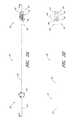
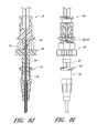
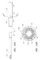
- FIG. 1Ais a perspective view of a preferred embodiment of an access device configured in accordance with the present invention and shows a pre-loaded guidewire section coaxially aligned with a needle, a dilator, and a medical article.
- FIG. 1Bis a plan view of the embodiment depicted in FIG. 1A .
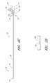
- FIG. 2Ais a plan view of the needle from FIG. 1A and shows a fenestration near a distal end.
- FIG. 2Bis a side view of the needle from FIG. 1A and shows a fin near a proximal end.
- FIG. 2Cis a cross-sectional view taken along the lines 2 C- 2 C in FIG. 2A .
- FIG. 2Dis an enlarged plan view of a portion of the needle of FIG. 2A and shows the fenestration.
- FIG. 2Eis an enlarged plan view of the needle hub of the needle of FIG. 2A .
- FIG. 2Fis an enlarged side view of the needle hub of the needle of FIG. 2A .
- FIG. 2Gis an enlarged proximal end view of the needle hub of the needle of FIG. 2A .
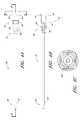
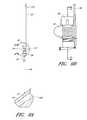
- FIG. 3Ais a plan view of the dilator from FIG. 1A and shows a fenestration near a distal end.
- FIG. 3Aalso shows longitudinally arranged grooves in the luer surface for venting air from between the dilator and sheath.
- FIG. 3Bis a cross-sectional view taken along the lines 3 B- 3 B in FIG. 3A .
- FIG. 3Cis an enlarged plan view of a portion of the dilator from FIG. 3A and shows the fenestration and longitudinal channel.
- FIG. 3Dis an enlarged end view of the dilator hub from FIG. 3A .
- FIG. 3Eis a perspective view of another embodiment of the dilator hub that includes a locking spin nut configured to secure to a sheath that has a corresponding screw thread.
- FIG. 3Fis a cross-sectional view taken along the lines 3 F- 3 F in FIG. 3A and shows the grooves equally spaced about the circumference of the luer surface.
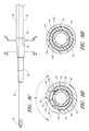
- FIG. 4Ais a plan view of the sheath from FIG. 1A and shows a sheath hub connected to a proximal end of a sheath.
- FIG. 4Bis a cross-sectional view taken along the lines 4 B- 4 B in FIG. 4A .
- FIG. 4Cis an enlarged end view of the sheath from FIG. 4A .
- FIG. 4Dis an enlarged perspective view of a proximal portion of the sheath from FIG. 4A .
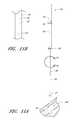
- FIG. 5Ais a perspective view of the guidewire section from FIG. 1A and shows a guidewire hub connected to a proximal end of a guidewire.
- FIG. 5Bis a plan view of the guidewire section of the embodiment depicted in FIG. 5A .
- FIG. 6Ais a perspective view of a track from FIG. 1A .
- FIG. 6Bis a plan view of the track in FIG. 6A and shows a locking mechanism for locking the needle relative to the dilator.
- FIG. 6Cis a side view of the track in FIG. 6B .
- FIG. 6Dan enlarged view of the locking mechanism from FIG. 6B .
- FIG. 6Eis an enlarged view of another locking mechanism that locks the guidewire section in a pre-loaded state.
- FIG. 7Ais a plan view of the access device from FIG. 1A and shows the locking mechanism from FIG. 6E with the guidewire section locked to the track in the pre-loaded state.
- FIG. 7Bis a side view of the access device and locking mechanism from FIG. 7A .
- FIG. 7Cis a cross-sectional view through the access device of FIG. 7A and shows the guidewire hub disposed between an element and stop of the track.
- FIG. 7Dis an enlarged end view of the access device from FIG. 7B and shows two arms extending from the track and around at least a portion of the guidewire hub.
- FIG. 8Ais a plan view of the embodiment depicted in FIG. 1A illustrating the insertion of the distal end of the access device into a patient.
- FIG. 8Bis an enlarged view of the embodiment depicted in FIG. 8A focusing on the area of the access device adjacent to the patient.
- FIG. 8Cis an enlarged view of a portion of the embodiment depicted in FIG. 8B and illustrates the needle opening or fenestration aligned with the dilator opening or fenestration in hidden lines.
- FIG. 8Dis an enlarged cross-sectional view of a portion of the embodiment depicted in FIG. 8C and shows the needle opening or fenestration aligned with the dilator opening or fenestration so as to allow fluid to flow from inside the needle to a channel formed between the sheath and dilator.
- FIG. 8Eis a graph showing the rate fluid is drawn up a channel with a gap height width of 0.002 inches.
- FIG. 8Fis a graph showing the rate fluid is drawn up a channel with a gap height width of 0.001 inches.
- FIG. 8Gis a graph showing the rate fluid is drawn up a channel with a gap height width of 0.0005 inches.
- FIG. 8His an enlarged cross-sectional view of a portion of the embodiment depicted in FIG. 8C taken through a region distal of the channel in the dilator.
- FIG. 8Iis an enlarged view of the embodiment depicted in FIG. 8A focusing on the area where the needle hub is locked to the dilator hub when the needle hub is in the first position.
- FIG. 8Jis a cross-sectional view of the embodiment depicted in FIG. 8I .
- FIG. 9Ais a side view of the embodiment depicted in FIG. 1A illustrating the guidewire advanced from the needle tip in a distal direction.
- FIG. 9Bis an enlarged view of the embodiment depicted in FIG. 9A focusing on the area where the guidewire hub is locked to the needle hub when the needle hub is in the first position.
- FIG. 9Cis a cross-sectional view of the embodiment depicted in FIG. 9B .
- FIG. 10Ais a side view of the embodiment depicted in FIG. 1A illustrating the dilator and sheath being advanced distally relative to the needle body from the position illustrated in FIG. 9A .
- FIG. 10Bis an enlarged rear view of the embodiment depicted in FIG. 10A focusing on the area where the needle hub is locked to the track when the needle hub is in the second position.
- FIG. 11Ais a side view of the embodiment depicted in FIG. 1A illustrating the removal of the guidewire, needle body, and dilator from the sheath.
- FIG. 11Bis an enlarged view of the portion of the embodiment illustrated in FIG. 11A showing the needle tip covered by the dilator during removal of the guidewire, needle body, and dilator from the sheath.
- FIG. 12Ais an enlarged plan view that illustrates another embodiment of the aligned openings or fenestrations in the needle and dilator.
- FIG. 12Bis an enlarged cross-sectional view along lines 13 B- 13 B in FIG. 12A and shows the needle opening or fenestration aligned with the dilator opening or fenestration so as to allow fluid to flow from inside the needle to a channel formed between the sheath and dilator.
- FIG. 13Ais an enlarged plan view that illustrates another embodiment of the aligned openings or fenestrations in the needle and dilator.
- FIG. 13Bis an enlarged cross-sectional view along lines 13 B- 13 B in FIG. 13A and shows the needle opening or fenestration aligned with the dilator opening or fenestration so as to allow fluid to flow from inside the needle to a channel formed between the sheath and dilator
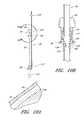
- FIG. 14Ais an enlarged plan view that illustrates another embodiment of the channel formed between the dilator and the sheath.
- FIG. 14Bis a cross-sectional view along lines 14 B- 14 B in FIG. 14A and shows the thickness of the channel extending into the sheath.
- FIG. 15Ais an enlarged plan view that illustrates another embodiment of the channel formed between the dilator and the sheath.
- FIG. 15Bis a cross-sectional view along lines 15 B- 15 B in FIG. 15A and shows the thickness of the channel extending into both the dilator and the sheath.
- FIG. 16Ais an enlarged plan view that illustrates another embodiment of the channel formed between the dilator and the sheath.
- FIG. 16Bis a cross-sectional view along lines 16 B- 16 B in FIG. 15A and shows a plurality of equally spaced channels in the form of splines extending into the dilator.
- FIG. 17is an enlarged cross-sectional view through another embodiment of the access device and shows the channel formed between a sheath and a dilator that have dissimilar shapes.
- FIG. 1Aillustrates an access device 20 that is configured to be inserted into a blood vessel (e.g., a vein or an artery) in accordance with a preferred embodiment of the present invention. While the access device is described below in this context (i.e., for vascular access), the access device also can be used to access and place a medical article (e.g., catheter or sheath) into other locations within a patient's body (e.g., a drainage site) and for other purposes (e.g., for draining an abscess).
- a medical articlee.g., catheter or sheath
- the present embodiment of the access deviceis disclosed in the context of placing an exemplary single-piece, tubular medical article into a body space within a patient. Once placed, the tubular article can then be used to receive other medical articles (e.g., catheters, guidewires, etc.) to provide access into the body space and/or be used to provide a passage way for introducing fluids into the body space or removing (e.g., draining) fluids from the body space.
- the tubular medical articleis a sheath or catheter that is configured primarily to provide a fluid passage into a vein.
- the principles of the present inventionare not limited to the placement of single piece sheaths or catheters, or to the subsequent insertion of a medical article via the sheath or catheter.
- the access device disclosed hereinalso can be successfully utilized in connection with placing one or more other types of medical articles, including other types of sheaths, fluid drainage and delivery tubes, and single or multi-lumen catheters directly in the patient or indirectly via another medical article.
- the access device disclosed hereincan also be configured to directly or indirectly place central venous catheters, peripherally inserted central catheters, hemodialysis catheters, surgical drainage tubes, tear-away sheaths, multi-piece sheaths, scopes, as well as electrical conduit for wires or cables connected to external or implanted electronic devices or sensors.
- the medical articles listed abovemay be directly placed in the patient via the dilator, needle, and guidewire of the access device or subsequently placed within the patient via a medical article that was placed within the patient via the dilator, needle, and guidewire of the access device.
- the embodiments disclosed hereinare not limited to co-axial insertion of a single medical article.
- two cathetersmay be inserted in the patient via an inserted sheath or a second catheter may be inserted in the patient via an inserted first catheter.
- the medical article inserted via the dilator, needle, and guidewirecan form a lumen that is in addition to the lumen(s) of the subsequently inserted medical article.
- the illustration and description of the access device in connection with a sheathis merely exemplary of one possible application of the access device.
- FIGS. 1A and 1Billustrated a preferred embodiment of an access device 20 .
- the access device 20comprises a needle 22 , a dilator 24 , and a sheath 26 .
- the access devicealso includes a guidewire section 28 and a track 30 .
- the dilator 24is preferably coaxially mounted on the needle 22
- the sheath 26is coaxially mounted on the dilator 24 .
- the telescoping nature of the access device's componentscan also be accomplished by arranging the components with their axes arranged substantially parallel rather than coaxially (e.g., a monorail-type design).
- each of these componentsincludes a luminal fitting at a terminal end or transition (i.e., a hub) and elongated structure that extends from the fitting.
- the needle 22includes a needle body 32 that extends distally from the needle hub 34
- the dilator 24includes a dilator shaft 36 that extends distally from a dilator hub 38
- the sheath 26includes a sheath body 40 that extends distally from a sheath hub 42
- the guidewire section 28comprises a guidewire 44 and preferably a guidewire hub or cap 46 .
- the guidewire hub 46is disposed on the proximal end of the guidewire 44 ; however, in other applications, the hub 46 can be disposed at a location between the ends of the guidewire 44 .
- FIGS. 2A-2Gillustrate the needle body 32 and needle hub 34 of the needle 22 , which are configured in accordance with a preferred embodiment of the access device, in isolation from the other components of the access device 20 .
- the needle hub 34is disposed on a proximal end of the needle body 32 .
- the needle body 32terminates at a distal end near a distal portion 50 of the needle 22
- the needle hub 34lies at a proximal portion 52 of the needle 22 .
- the needle body 32preferably has an elongated tubular shape having a circular, constant-diameter inner bore and a circular, constant-diameter exterior surface. In other embodiments, however, the needle body 32 can have other bore and exterior shapes (such as, for example, but without limitation, an oval cross-sectional shape).
- the interior or exterior of the needlecan also include grooves or channels. The grooves or channels may guide fluids within the needle bore either around or to certain structures of the needle 22 or within the needle 22 (e.g., around the guidewire). In some embodiments, the grooves or channels may assist in maintaining a desired orientation of the needle 22 with respect to the dilator.
- the needle body 32has a sufficiently long length to access a targeted subcutaneous body space and has a sufficient gauge size to withstand the insertion forces when accessing the body space without causing undue trauma.
- the needle bodycan have a length between 3-20 cm, and more preferably between 3-10 cm.
- the needle body 32preferably has a length of 7 cm or greater, and more preferably has a length of 9 cm or greater, and most preferably has a length of 9 to 10 cm.
- the size of the needlepreferably is 18 gauge or smaller, and more preferably between 18-28 gauge, and most preferably between 18-26 gauge for micro-puncture applications (peripheral IVs).
- the length and gauge of the needle body 32should be significantly shorter and smaller, for example preferably between 3-4 cm and between 26-28 gauge.
- the needle body 32includes at least one fenestration or opening 56 near a distal end of the needle body 32 .
- the fenestration 56extends through the wall of the needle body 32 and can have a variety of shapes and orientations on the needle body 32 , as described in detail below.
- the needle body 32can have a bevel tip 54 disposed on the distal portion 50 .
- the fin 58is preferably disposed at a circumferential location around the needle hub 34 that is aligned with the circumferential locations of the bevel on the needle tip and the opening or fenestration 56 in the needle. That is, the fin 58 is indexed with the bevel and fenestration.
- the physician or healthcare providercan determine the orientation of the beveled needle tip (and the fenestration 56 ) by noting the orientation of the exposed fin 58 even though the bevel is inside the vessel and the fenestration is covered by the sheath and/or dilator.
- an orientation of the fin 58 away from the patientcoincides with a bevel up orientation of the needle tip within the vessel.
- the fenestration 56is also on the same side as the fine 58 , as seen in FIG. 2C .
- the illustrated embodiment of the needle hub 34has a finger-hold, tab or fin 58 .
- the fin 58provides a grasping region to manipulate the needle hub 34 .
- a physician or healthcare providercan place an index finger and thumb on the sides of the fin 58 to stabilize the needle hub 34 , relative to the dilator 24 and/or sheath 26 .
- the needle hub 34slides relatively along the track 30 between a first position 121 and a second position 123 .
- the fin 58can be held when performing the insertion step (which will be described below).
- the fin 58can be used to stabilize the needle hub 34 while rotating the dilator hub 38 . Furthermore, the fin 58 can be used by a physician or healthcare provider as an aid to grasp the access device 20 when the needle hub 34 is disposed at any position along the track 30 .
- FIG. 2Dis an enlarged view of the side opening or fenestration 56 in the needle body 32 .
- the one or more fenestration 56provides a path through the side of the needle body 32 .
- the fenestration 56 illustrated in FIG. 2Dhas an oblong shape.
- the shape of the side opening 56is not limited to the illustrated embodiment and may be round, oblong, square, or another shape.
- the needle hub 34preferably includes locking structures at the proximal portion and distal portion of the needle hub 34 .
- These locking structuresmay be a luer-thread-type or another type of connections.
- the locking structure on the proximal portion 52 of the needle hub 34allows the physician or healthcare provider to secure another medical article to the proximal end of the needle hub 34 .
- the needle hub 34 in the illustrated embodimentincludes an annular flange or lip 63 .
- the lip 63is threaded to allow the needle hub 34 to attach to other medical articles with a corresponding luer-nut locking feature.
- a physician or healthcare providermay attach a syringe or monitoring equipment to the locking structure on the proximal end to perform other procedures as desired.
- the needle hub 34can also include a septum at its proximal end and/or a side port if these features are desirably for a particular application.
- the locking structure on the distal portion of the needle hub 34allows the physician or healthcare provider, for example, to lock the needle hub 34 to the dilator hub 38 when the needle hub 34 is in the first position 121 .
- the locking structureincludes a latch element 66 on the needle hub 34 .
- the latch element 66releasably locks the needle hub 34 to the dilator hub 38 .
- the locking structureallows the healthcare provide to advance the needle into a patient while grasping the needle hub 34 , the dilator hub 38 or both.
- the guidewire 44is introduced through a hollow portion 62 of the needle hub 34 , through the needle body 32 , and into a punctured vessel.
- the guidewire 44allows the healthcare provider to guide the dilator 24 and sheath 26 into the vessel.
- the needle hub 34may also comprise two tangs 68 that allow the needle hub 34 to slide along the track 30 between a first position 121 and a second position 123 . While in the preferred embodiment the two tangs 68 of the needle hub 34 are engaged with the track 30 between the first position 121 and the second position 123 , in other embodiments the needle hub 34 is only engaged with the track 30 over a portion of the length of the track 30 between the first position 121 and the second position 123 .
- the sliding interconnection between the track 30 and the needle hub 34also can be accomplished using other cooperating structures (e.g., a corresponding pin and tail of dovetail connection).
- FIG. 3Ais a plan view of the dilator 24 of the embodiment depicted in FIG. 1A .
- FIG. 3Bis a cross-sectional view of the dilator 24 of the embodiment depicted in FIG. 3A , taken along line 3 B- 3 B.
- the illustrated dilator 24comprises a dilator shaft 36 , a dilator hub 38 , a distal region 70 , and a proximal region 72 .
- the dilator shaft 36includes a side openings or fenestrations 74 ; however, in other embodiments, the dilator shaft 36 can include fewer or greater numbers of fenestrations 74 .
- the dilator shaft 36may not include a fenestration 74 where a blood flash chamber(s) is disposed within the dilator (as will be described in more detail below).
- the dilator hub 38may comprise one or more vents.
- the vents in the dilator hub 38are formed by grooves 75 .
- the dilator shaft 36may comprise one or more longitudinal channels formed in the outer surface of the dilator shaft 36 .
- the channelis an open channel.
- the side walls of the open channelare formed by ridges 76 .
- the ridges 76define generally smooth, arcuate exterior surfaces that interface with the sheath 26 ; however, in other embodiments, the ridges can have other shapes (e.g., can defined more pronounced apexes).
- FIG. 3Cis an enlarged plan view of a portion of the embodiment illustrated in FIG. 3A .
- the illustrated dilator shaft 36comprises one or more side openings 74 and one or more channels formed between ridges 76 .
- the side opening or fenestration 74provides a fluid path through the side of the dilator shaft 36 .
- the shape of the side opening 74is not limited to the illustrated embodiment and may be round, oblong, square, or have another shape.
- the opening or fenestration 74 illustrated in FIG. 3Chas an oblong shape.
- the opening 74 in the dilator shaft 36has an oblong shape with its major axis being non-parallel relative to the major axis of the oblong opening 56 in the needle.
- the needle opening 56may extend in a longitudinal direction and the dilator opening 74 may extend in a circumferential direction or vice versa.
- the long axis of the dilator opening 74is disposed generally perpendicular to the long axis of the needle opening 56 .
- these openings 56 , 76can have other shapes, sizes and orientations that preferably obtain a significant degree of overlap to account for manufacturing tolerances and rotational misalignments.
- one of the fenestrationshas a greater dimension in at least one direction than the other one of the fenestrations in the same direction. Accordingly, in the illustrated embodiment, the needle fenestration 56 has a longer longitudinal dimension than the longitudinal dimension of the dilator fenestration 74 .
- the channel formed between the ridges 76extends in a proximal direction from a point distal to the opening 74 .
- the ridges 76 in the illustrated embodimentare disposed along the dilator shaft 36 and on opposite sides of the dilator shaft 36 so as to balance the dilator shaft 36 within the sheath.
- the ridges 76form two channels there between. Balancing the dilator within the sheath allows the dilator to apply equal pressure to the inside circumference of the sheath.
- the dilator hub 38may include locking structures at the proximal region 72 and the distal region of the dilator 24 .
- Each locking structuremay be a luer type or other type of connection.
- the dilator hub 38comprises a first luer connection 78 , a second luer connection 80 , a lip 77 , and a base 79 .
- the first luer connection 78engages to the needle hub 34 on the needle 22 illustrated in FIG. 2E .
- the second luer connection 80is disposed distal to the first luer connection 78 .
- the second luer connection 80(e.g., a male luer slip connector) can be configured to engage to the sheath hub 42 (e.g., a female luer slip connector) on the sheath 26 illustrated in FIG. 1A . Additionally, the male-female lure slip connectors on these components can be reversed.
- FIG. 3Dis an enlarged proximal end view of the dilator 24 of FIG. 3A .
- the dilator hub 38comprises an opening 82 that releasably engages the latch element 66 on the needle hub 34 illustrated in FIG. 2E-2F to secure the dilator hub 38 to the needle hub 34 when the needle hub 34 is in the first position 121 .
- the male-female lure slip connectors on the dilator hub and the needle hub 34can also be reversed in other embodiments.
- the color of the dilator 24may be selected to enhance the contrast between the blood or other fluid and the dilator 24 .
- bloodis observed flowing between the dilator 24 and the sheath to confirm proper placement of the needle in a blood vessel.
- the sheathis preferably manufactured from a clear or transparent material with the dilator 24 having a color that contrasts with the color of the fluid.
- the dilator 24may have a white color to enhance its contrast with red blood. Other colors of dilator 24 could be employed depending on the color of the fluid and the degree of contrast desired.
- the dilator 24may be manufactured of a clear or transparent material similar to the sheath to allow the physician to observe the blood flash through both the sheath and dilator 24 .
- FIG. 3Eis an enlarged perspective view of another embodiment of a dilator hub 38 A.
- the dilator hub 38 Ais similar to the dilator hub 38 illustrated in FIG. 3A except that the dilator hub 38 A further includes a spin nut or collar 84 .
- the proximal end of the spin nut 84rotates about an annular groove 73 in the dilator hub 38 (see FIG. 3A ). Once disposed within the annular groove 73 , the spin nut 84 is inhibited from moving in the distal direction but is free to rotate about the dilator hub 38 A.
- the spin nut 84can have an interengaging element that locks to a corresponding interengaging element on the sheath 26 .
- the spin nut 84includes an internal thread which engages with an external thread on the sheath hub 42 on the sheath 26 illustrated in FIG. 1A .
- the dilator 24 or sheath 26may separately, or together, form one or more passages to allow air or gas to escape or vent from between the dilator 24 and sheath 26 and/or between the needle and the dilator.
- the one or more passagesmay further be sized to inhibit the flow of a liquid, such as blood, while allow air to pass therethrough.
- the one or more passagesmay be in the wall of the sheath 26 , the sheath hub, the dilator hub 38 , an exposed section of the dilator shaft, and/or formed between adjacent surfaces of the dilator 24 and sheath 26 .
- FIG. 3Ashows longitudinally arranged grooves 75 that are formed between adjacent surfaces of the dilator 24 and sheath 26 .
- Such venting passagescan also be labyrinth.
- the adjacent surfacesform a luer slip connection between the sheath 26 and dilator 24 .
- FIG. 3Fis a cross-sectional view taken along lines 3 F- 3 F in FIG. 3A and shows the grooves 75 equally spaced, though not required to be equally spaced, about the circumference of the luer slip surface.
- the grooves 75are sized to allow air to escape from between the dilator and the medical article, such as a sheath, when the blood flash occurs.
- the one or more passagesneed not be in the form of a surface groove 75 and instead may be in the form of an opening or passageway.
- the one or more passagesallow air to pass through the luer connection between the sheath and dilator hubs.
- a distal end of the passage 75or is located on the distal side of the luer connection with the proximal end of the passage 75 being located on the proximal side of the luer connection.
- the one or more passagesmay be sized to filter blood or other liquid or may include a filter or other structure that inhibits the passage of a liquid while allowing the passage of air.
- the sheathitself may include one or more passages in the form of small openings, pores or porous material.
- the one or more small openings, pores or porous material in the sheathcan form a porous vent that allows air to pass yet retain blood.
- an extrusion processis used to create a long tubular body having one or more longitudinal grooves or channels on its outer diameter (OD) or within the substance of the dilator.
- the long tubular bodyexceeds the required length of a single dilator and preferably has a length that is many times greater than the length of a single dilator.
- a manufacturing dieis employed in the extrusion process having geometry that reflects the desired geometry for the inside and outside diameters of the dilator and the thickness and circumferential span of the longitudinal grooves or channels or interior channels. In the illustrated embodiment of FIGS.
- the long tubular bodyincludes two longitudinal OD channels on opposite sides of the body to enhance the balance of the dilator within the sheath.
- a single channelcan provide a visible indicator for the blood flash.
- the two channelspreferably extend along the length of the extruded tubular body.
- the illustrated embodimentincludes one or more channel disposed between the dilator and the sheath, one or more channels can in addition or in the alternative be formed between the needle and the dilator, within the dilator, and/or within the sheath.
- the dilator 24thus is made partially or completely from clear, translucent, transparent, or semi-opaque material to visualize the fluid flash within the channel.
- the extruded tubular bodyis cut to the appropriate length for a single dilator.
- the two OD groovesextend for the entire length of the cut dilator.
- a tipping processis then employed on an end of the cut dilator to reform the tip.
- An end of the cut dilatoris forced into a die/mandrel having geometry that matches the desired geometry of the tip of the finished dilator.
- the desired geometryis selected depending on, for example, the inside diameter of the sheath. It is desirable for the sheath and dilator to form a close fit or seal near the tip to promote blood flow in the proximal direction up the channel formed between the grooved dilator and sheath.
- the OD of the dilator in the tip regiontapers in the distal direction.
- thermal energyis applied to the tip to reform the tip to match the die/mandrel.
- the thermal energymay be applied by any known technique, including using radiant heating from an infrared or RF heat source.
- the dilator in the tip regionis reformed so that the grooves are essentially removed. With the grooves removed, the dilator is able to form the close fit or seal with the sheath near the tip.
- the groovesare maintained along the remainder of the dilator on the proximal side of the location where the tip of the sheath 26 sits on the dilator. After removal from the die/mandrel, the tip end of the dilator may be cleaned and cut as necessary to remove any manufacturing remnants.
- the one or more fenestrations in the dilatoris cut through the dilator near the tip region and in or near the groove.
- Each fenestrationmay be cut by any known means, including a drill or laser. Further, the cutting device may be moved with respect to the dilator or vice versa to achieve an oblong or other shape for the fenestration.
- the end of the dilator opposite from the tip endcan be flared to facilitate over molding the dilator hub onto the dilator.
- FIG. 4Ais a plan view of the sheath 26 of the embodiment depicted in FIG. 1A .
- FIG. 4Bis a cross-sectional view of the sheath 26 of the embodiment depicted in FIG. 4A , taken along line 4 B- 4 B.
- FIG. 4Cis an enlarged proximal end view of the sheath 26 of FIG. 4A .
- FIG. 4Dis an enlarged perspective view of the sheath hub 42 of the sheath 26 of FIG. 4A .
- the sheath 26may comprise a sheath body 40 , a sheath hub 42 , a distal portion 90 , and a proximal region 92 .
- the sheath body 40may be made partially or completely from clear, translucent, transparent, or semi-opaque material.
- the sheath body 40can also include one or more radiopaque markers, such as, for example, barium sulfate stripes.
- the sheathincludes two such radiopaque stripes disposed on diametrically opposite sides of the body 40 .
- the sheath body 40may be a single piece sheath through which a catheter or other medical article (e.g., a guidewire) is inserted into the vessel.
- the sheath body 40forms a conduit for insertion of the catheter or other medical article (e.g., a guidewire).
- the sheath or a portion of the sheathcan form a lumen that is in addition to the lumen(s) of the catheter.
- an equivalent to a triple lumen cathetercan be formed by inserting a dual lumen catheter through the sheath body 40 with the sheath body 40 itself forming a third lumen.
- a peel-away sheathcan include perforations, serrations, skives, or other structures, or include other materials (e.g., PTFE with bismuth) to allow the physician or healthcare provider to remove easily a portion or the entire sheath body 40 .
- the sheath hub 42may include a luer slip connection and a lock member 94 .
- the locking member 94may comprise a locking or attaching structure that mates or engages with a corresponding structure.
- the lock member 94can be a luer connection 94 which can be configured to engage with the second luer connection 80 of the dilator hub 38 .
- the sheath hub 42preferably is designed so that the locking mechanism or second luer connection 80 of the dilator hub 38 can enter the sheath hub 42 substantially unobstructed.
- the physician or healthcare providercan push, pull, or twist the sheath hub 42 and possibly disengage or engage the locking member 94 with a corresponding connector on another medical article.
- the locking member 94can be, for example, a luer connection, a protruding bump, dent, etc., that creates a mechanical fit so that the dilator hub 38 and the sheath hub 42 are releasably interlocked.
- the locking member 94 of the sheath hub 42comprises a luer connection.
- the sheath hub 42preferably engages with the corresponding second luer connection 80 on the dilator hub 38 .
- the locked positioncan be disengaged or engaged by pulling, squeezing, pushing or twisting the dilator hub 38 relative to the sheath hub 42 .
- the sheath hub 42can comprise a lip 95 .
- the lip 95can be threaded to allow the sheath hub 42 to attach to other medical articles with a corresponding locking feature.
- the sheath hub 42preferably comprises one or more surface features to allow the physician or healthcare provider to easily grasp or manipulate the sheath 26 and/or access device 20 .
- the sheath hub 42includes a squared grip 96 and ridges 98 .
- the sheath hub 42may comprise radially extending wings or handle structures to allow for easy release and removal of the sheath body 40 from other parts of the access device 20 .
- the wingsare sized to provide the healthcare provider with leverage for breaking apart the sheath hub 42 .
- the sheath hub 42may comprise a thin membrane connecting the halves of the sheath hub 42 . The membrane is sized to keep the halves of the sheath hub 42 together until the healthcare provider decides to remove the sheath hub 42 from the access device. The healthcare provider manipulates the wings to break the membrane and separate the sheath hub 42 into removable halves.
- FIG. 5Ais a perspective view of the guidewire section 28 of the embodiment depicted in FIG. 1A .
- FIG. 5Bis a plan view of the guidewire section 28 depicted in FIG. 5A , which preferably includes the guidewire hub 46 .
- the guidewire hub 46can comprise one or more surface features to allow the physician or healthcare provider to easily grasp or manipulate the guidewire hub 46 and/or access device 20 .
- the guidewire hub 46comprises one or more ridges 110 . In a pre-loaded state, the outer surface of the guidewire hub 46 engages with a locking mechanism 130 on the track 30 when the guidewire hub 46 is in a third position 125 .
- the guidewire 44may form a close fit with the inside diameter of the needle body so as to provide a self-aspirating function when retracted.
- an outside diameter of the guidewire 44may be selected to form a close fit with the needle along the length of the guide wire or along only a portion of the guidewire 44 .
- the distal end portion of the guidewirecan have a reduced diameter in comparison to other sections of the guidewire.
- the size of such reduced diameter sectioncan be selected to permit fluid to pass to the fenestration 56 in the needle body even when the guidewire has been advanced beyond the distal tip of the needle.
- FIG. 6Ais a perspective view of the track 30 of the embodiment depicted in FIG. 1A .
- FIG. 6Bis a plan view of the track 30 illustrated in FIG. 6A .
- FIG. 6Cis a side view of the track 30 illustrated in FIG. 6A . As shown in FIGS.
- the track 30 in the illustrated embodimentcomprises a distal portion 120 , a proximal portion 122 , a distal locking member 124 that connects the track to the dilator hub 38 , a locking mechanism 128 that inhibits further proximal and distal movement of the needle hub 34 once the needle hub 34 is slid from the first position 121 to the second position 123 along the track 30 , and a locking mechanism 130 that allows the guidewire hub 46 to attach to the track 30 when the guidewire hub is in the pre-loaded state or third position 125 .
- the trackis made of polycarbonate material; however, as explained below, other materials can be used.
- the track 30may further include a track section 132 of reduced width as shown most clearly in FIGS. 6A and 6B .
- the reduced widthfacilitates assembly of the needle hub to the track 30 .
- the illustrated embodimentincludes a rib 133 on the distal portion 120 of the track 30 .
- the rib 133provides additional structural reinforcement between the distal locking member 124 and the remainder of the track 30 .
- the distal locking member 124connects to the dilator 24 and allows the track 30 to extend proximally from the dilator 24 .
- the locking member 124can comprise two curved arms 124 that connect to the dilator hub 38 between the dilator hub lip 77 and the dilator hub base 79 .
- the locking member 124limits movement of the track 30 in a distal or proximal direction relative to the dilator hub 38 but allows the track 30 to rotate freely around the dilator hub 38 .
- FIG. 6Dis an enlarged view of a portion of the embodiment depicted in FIG. 6B .
- the locking mechanism 128is formed by varying the width of the track in the region of the second position 123 .
- the illustrated embodimentincludes a track section 134 of increasing width in the distal direction, a track section 136 of reduced width distal to the track section 134 of increasing width, and two finger elements 138 .
- the two finger elements 138project from the distal end of the track section 136 toward the proximal end of the track 30 and flare away from the longitudinal axis of the track 30 .
- FIG. 6Eis an enlarged view of a portion of the embodiment depicted in FIG. 6B .
- the locking mechanism 130is formed by a clip, clasp or other structure that engages with a portion of the guidewire hub or with a portion of the track 30 when the guidewire hub is in the third position. Some or all of the engagement structure may be part of the track 30 , be part of the guidewire hub, or be split between the track 30 and guidewire hub. In the illustrated embodiment, the locking mechanism 130 extends from the track 30 and engages with the guidewire hub.
- the locking mechanism 130comprises a rectangular element 140 protruding from the track 30 , two track arms 142 projecting from the track 30 distal to the rectangular element 140 , and a stop 144 protruding from the track 30 distal to the track arms 142 .
- the locking mechanism between the needle hub and the dilatorresides on the proximal side of the dilator hub.
- the locking mechanismcan be disposed at other locations as well.
- the locking mechanismincludes two pivotal levers which are joined by a locking hinge
- the locking mechanismcan be disposed radially relative to the needle hub.
- one leveris pivotally coupled to the dilator and the other lever is pivotally coupled to the needle.
- an elongated structurecan extend parallel to the needle body from the needle hub within the dilator.
- additional structure of the locking mechanisme.g., a detent
- the locking mechanism operating between the needle and the dilatorcan be disposed at a variety of locations relative to the dilator hub.
- FIG. 7Ais an enlarged plan view of the access device of the embodiment depicted in FIG. 1A pre-loaded with the guidewire.
- FIG. 7Bis a side view of the embodiment depicted in FIG. 7A .
- FIG. 7Cis a cross-sectional view of the embodiment depicted in FIG. 7A along line 7 C- 7 C.
- FIG. 7Dis a proximal end view of the access device 20 of FIG. 7A .
- the guidewire hub 46is locked to the track 30 when the guidewire hub 46 is located in a third position 125 . In this position, the guidewire hub 46 can be secured to the track 30 between the rectangular element 140 and the stop 144 .
- the guidewire hub 46can releasably lock between the rectangular element 140 and the stop 144 .
- the track arms 142can further secure the guidewire hub 46 to the track 30 .
- This locking mechanismcan arrest unintended rotational and axial movement of the guidewire 44 at least in the distal direction when the guidewire hub 46 is in the third position 125 .
- the healthcare providermay disengage the guidewire hub 46 from the track 30 to allow distal movement of the guidewire through the access device 20 .
- the needle hub 34is locked to the dilator hub 38 when the needle hub 34 is in the first position 121 .
- the openings or fenestrations in the needle and dilatorare in register or in alignment with each other.
- the needle 22 and the dilator 24are inhibited from at least unintentional rotational and axial movement relative to each other.
- the fenestrations or openingsmaintain their general alignment.
- the dilator hub 38In the pre-loaded state, the dilator hub 38 is secured to the sheath hub 42 . This can inhibit at least unintentional rotational and axial movement between the dilator 24 and the sheath 26 . In embodiments where the sheath hub 42 and the dilator 24 have only a luer slip connection, the dilator 24 and sheath hub 42 may rotate relative to each other.
- FIG. 8Ais a plan view of the embodiment depicted in FIG. 1A that illustrates an operational step of one method of using the access device 20 .
- FIG. 8Adepicts the needle body 32 of the access device 20 inserted into a vessel 148 , such as a vein. While the described method refers to vascular access, the access device 20 also can be used to access and place a catheter or sheath into other locations within a patient's body (e.g., for draining an abscess) and for other purposes.
- FIG. 8Bis an enlarged plan view of the portion of the embodiment illustrated in FIG. 8A which is circled by line 8 B- 8 B.
- FIG. 8Cis an enlarged plan view of the portion of the embodiment illustrated in FIG. 8B which is circled by line 8 C- 8 C.
- FIG. 8Dis an enlarged cross-sectional view of the embodiment depicted in FIG. 8C along line 8 D- 8 D.
- the needle body 32comprises one or more side openings 56 in its side wall.
- the dilator shaft 36comprises one or more side openings 74 .
- the side openings 56 , 74may have the same or different shapes as well as aspect ratios.
- the side opening 56 in the needle body 32has a different aspect ratio than the side opening 74 in the dilator shaft 36 .
- the side opening 56 in the needle body 32is elongated in one direction (e.g., substantially parallel to the longitudinal axis of the needle body 32 ).
- the side opening 74 in the dilator shaft 36is elongated in a different direction (e.g., along the circumference of the dilator shaft 36 ).
- FIGS. 8A-Dillustrate the alignment between only one set of corresponding side openings. Other sets of side openings can also be aligned or be misaligned depending upon the relative orientations of the needle body 32 and the dilator shaft 36 .
- the dilator shaft 36is coaxially positioned to minimize an annular space 150 between the needle body 32 and the dilator shaft 36 .
- the inner surface 152 of the dilator shaft 36need not, though it can, lie directly against the outer-surface 154 of the needle body 32 .
- the annular space 150 between the outer-surface 154 of the needle body 32 and the inner surface 152 of the dilator shaft 36is minimized to inhibit the flow of blood or its constituents (or other bodily fluids) into the annular space 150 between the dilator shaft 36 and needle body 32 .
- this featureminimizes the blood's exposure to multiple external surfaces and reduces the risk of contamination, infection, and clotting.
- the dilator shaft 36is coaxially mounted to the needle body 32 such that at least part of one side opening 56 disposed on the needle body 32 is rotationally aligned with at least part of one side opening 74 on the dilator shaft 36 .
- the needle body 32 and dilator shaft 36maintain rotational alignment so that blood flows through the needle side opening 56 and dilator side opening 74 .
- the sheath body 40is preferably made partially or completely from clear, semi-opaque, translucent, or transparent material so that when blood flows into the needle body 32 , (1) through the needle side opening 56 , (2) through the dilator side opening 74 , and (3) into a channel 156 , the physician or healthcare provider can see the blood.
- the channel 156is formed between the dilator shaft 36 and the sheath body 40 and defined by one or more ridges 76 on the dilator shaft 36 .
- the channel 156is formed within a wall of the dilator shaft 36 with the dilator shaft 36 preferably comprising a transparent material. Blood will indicate to the physician or healthcare provider that the bevel tip 54 of the needle body 32 has punctured a vessel 148 .
- the needle body 32 and dilator shaft 36may (both) have multiple side openings where some or all of these side openings can be rotationally aligned.
- the channel 156can have an axial length that is almost coextensive with the length of the sheath 26 .
- the channel 156can be significantly smaller than the elongated channel 156 just described.
- the channel 156can be disposed within a distal, mid and/or proximal portion(s) of the sheath 26 .
- the channel 156alternatively can have a linear, curved or spiral shape along an axial length of the sheath 26 or can be formed by a plurality of such shapes.
- the channel 156may have various thicknesses and span angles. The thickness of the channel 156 can range from almost close to zero to 0.010 inches.
- the channel 156has a thickness of about 0.0005 to about 0.003 inches. More preferably, the channel 156 can have a thickness of about 0.001 inches to about 0.002 inches.
- the channel 156can have a span angle ⁇ about the axis of the dilator 24 of about 30 degrees to about 210 degrees or more, but preferably less than 360 degrees. More preferably, the channel 156 can have a span angle ⁇ of about 60 to 150. In the illustrated embodiment, the channel 156 spans 120 degrees.
- the thickness and span angle ⁇can be chosen so as to optimize the capillary action that occurs within the channel 156 as fluid (e.g., whole blood) enters the channel 156 as may further be selected based on the expected pressure in the body cavity and viscosity of the liquid.
- fluide.g., whole blood
- FIGS. 8E-8Gare graphs of test data illustrating how quickly a fluid is drawn up the surfaces of the channel 156 when the span angle is 120 degrees, the contact angle ( ⁇ ) is 5 degrees, and the circumferential length (H) is 0.64 mm at 60 degrees.
- the filling length (mm)is plotted on the y-axis
- time (seconds)is plotted on the x-axis.
- the testswere performed at hydrodynamic pressures similar to pressures experienced in peripheral vessels.
- FIG. 8Eillustrates the rate fluid is drawn up a channel 156 with a gap height width of 0.002 inches
- FIG. 8Fillustrates the rate fluid is drawn up a channel 156 with a gap height width of 0.001 inches
- 8Gillustrates the rate fluid is drawn up a channel 156 with a gap height width of 0.0005 inches. As shown in FIGS. 8E-G , fluid is drawn up the fastest in a channel with a gap height width of 0.0005 inches, followed by a channel with a gap height width of 0.001 inches, followed by a channel with a gap height width of 0.002 inches.
- the shape of the channel 156 described above and the resulting capillary actionwas optimized for use with whole blood as opposed to other fluids having a different viscosity than whole blood (e.g. leukocytes, pus, urine, plasma).
- the shape of the channel 156is not limited to the disclosed shape and may be optimized for draining other liquids, such as pus.
- the shape of the channel 156 described abovewas optimized for peripherally located vessels where the pressure in the vessel enhances the capillary action and resulting blood flash as well as for vessels located in the regions where the pressure may be low. For example, in the thorax region of the body, the expected pressure in the veins may be lower than in a peripherally located vein when the patient breathes.
- a different size of the channel for use of the access device 20 in other regions of the bodymay be employed taking into account the expected pressure within the vessel or body cavity.
- an outer-surface 160 of the dilator shaft 36 and/or an inner surface 158 of the sheath body 40can be coated with a substance to promote or enhance the capillary action within the channel 156 .
- a hydrophilic substancecan be used to coat outer-surface 160 of the dilator shaft 36 and/or the inner surface 158 of the sheath body 40 to enhance capillary action.
- one or both of these componentscan be made of a hydrophilic material.
- a hydrophilic substanceadditionally can be applied to the outer surface of the sheath 26 to act as a lubricant to ease insertion of the sheath 26 into a patient.
- lubricants or lubricous coatingscan be used on the exterior of the sheath 26 or at least the outer surface of the sheath can be formed of a lubricous material. Additionally, the sheath 26 can be coated or formed with agents (e.g., heparin), which elute from the sheath, to facilitate the clinical application of the access device 20 .
- agentse.g., heparin
- FIG. 8His a cross sectional view of the embodiment depicted in FIG. 8C along line 8 H- 8 H.
- the sheath body 40is coaxially positioned to minimize the annular space 157 between the sheath body 40 and the dilator shaft 36 while still allowing relative movement of the sheath body 40 and the dilator shaft 36 .
- the inner surface 158 of the sheath body 40need not, though it can, lie directly against the outer-surface 160 of the dilator shaft 36 .
- the annular interface 157 between the outer-surface 160 of the dilator shaft 36 and the inner surface 158 of the sheath body 40may be reduced in this region to inhibit the distal flow of blood or its constituents (or other bodily fluids) from the opening 74 in the dilator shaft 36 .
- FIG. 8Iis an enlarged plan view of the portion of the embodiment illustrated in FIG. 8A which is circled by line 8 I- 8 I.
- FIG. 8Jis a cross-sectional view of the embodiment depicted in FIG. 8I .
- FIGS. 8I and 8Jillustrate the needle hub 34 locked to the dilator hub 38 when the needle hub is in the first position 121 .
- the dilator shaft 36may be coaxially mounted to the needle body 32 by slipping a hollow section 84 of the dilator shaft 36 over the needle body 32 and releasably securing the dilator hub 38 to the needle hub 34 .
- the proximal end 86 of the dilator hub 38is configured to mechanically fit and interlock with the needle hub 34 .
- the dilator shaft 36may be releasably mounted to the needle body 32 so that the dilator shaft 36 can be mounted and released, or vice versa, from a coaxial position relative to the needle body 32 .
- This locking mechanismcan inhibit at least some unintentional rotational and axial movement between the needle 22 and the dilator 24 when the needle hub 34 is in the first position.
- the needle hub 34may have a luer connection 64 that locks to the luer connection 78 of the dilator hub 38 .
- the needle hub 34may also have latch element 66 that locks to the opening 82 in the dilator hub 38 .
- FIGS. 8I and 8Jillustrate the dilator hub 38 engaged with the sheath hub 42 when the access device 20 is inserted into a vessel 148 .
- the proximal end 86 of the sheath hub 42is configured to mechanically fit and releasably engaged with the dilator hub 38 .
- the luer connection 80 in the dilator hub 38can engage with the lock member 94 of the sheath hub. The resulting friction fit can inhibit at least some unintentional rotational and axial movement between the dilator 24 and the sheath 26 when the access device 20 is inserted into a vessel 148 .
- FIG. 9Ais a side view of the embodiment depicted in FIG. 1A that illustrates a further operational step of the access device 20 .
- FIG. 9Adepicts the guidewire 44 of the access device 20 advanced in a distal direction into a vessel 148 . This can be achieved by advancing guidewire hub 46 from the third position 125 in a distal direction. The guidewire hub 46 is then locked to the needle hub 34 when the needle hub 34 is in the first position 121 .
- FIG. 9Bis an enlarged side view of the portion of the embodiment illustrated in FIG. 9A which is circled by line 9 B- 9 B.
- FIG. 9Cis a cross-sectional view of the embodiment depicted in FIG. 9B .
- FIG. 9Cillustrates the locking mechanism between the guidewire hub 46 and the needle hub 34 .
- the guidewire hub 46is configured to mechanically fit and releasably or irreversibly interlock with the needle hub 34 .
- the guidewire hub 46includes a nub 162 on the inner surface of the guidewire hub 46 .
- the nub 162 of the guidewire hubcan lock onto the needle hub 34 by advancing the guidewire hub 46 in a distal direction until the nub 162 is secured within the threaded groove on the lip of the needle hub 46 .
- the guidewire hub 46can lock to the needle hub 34 via corresponding threaded elements.
- FIG. 10Ais a side view of the embodiment depicted in FIG. 1A that illustrates another operational step of the access device 20 .
- FIG. 10Adepicts the dilator shaft 36 and the sheath body 40 advanced in a distal direction into a vessel 148 . This can be achieved by releasing the dilator hub 38 from the needle hub 34 and advancing the dilator 24 and sheath 26 in a distal direction relative to the needle hub 34 along the guidewire and needle.
- FIG. 10Afurther illustrates the proximal movement of the needle 22 and guidewire section 28 relative to the dilator 24 and the sheath 26 .
- the needle hub 34will lock to the track 30 when the needle hub 36 reaches the second position 123 .
- FIG. 10Bis an enlarged rear view of the portion of the embodiment illustrated in FIG. 10A which is circled by line 10 B- 10 B.
- the needle hub 34locks onto the track 30 via the locking mechanism 128 in the second position 123 .
- the needle hub tangs 68slide in a proximal direction over the track fingers 138 and the tangs 68 can lock into place between the track fingers 138 and the track section of increasing width 134 . This arrests and, more preferably, substantially irreversibly prevent axial movement of the needle body 32 at least in the distal direction when the needle hub 34 is in the second position 123 .
- the locking mechanism 128irreversibly prevents the needle hub 34 from moving in either the proximal or distal directions once engaged. Furthermore, the distal tip 54 of the needle 22 is drawn into the dilator 24 to sheath the distal tip 54 when the needle hub 34 is in the second position 123 . Thus, this locking mechanism 128 inhibits the bevel tip 54 disposed on the distal portion 50 of the needle body 32 from being advanced beyond the distal end of the dilator shaft 36 once the dilator shaft 36 has been advanced over the needle body 32 during use. The dilator shaft 36 thus sheaths the sharp bevel tip 54 of the needle body 32 to inhibit accidental needle sticks from occurring.
- FIG. 11Ais a side view of the embodiment depicted in FIG. 1A that illustrates the final operational step of the access device 20 .
- FIG. 11Aillustrates the removal of the guidewire 44 and the dilator shaft 36 from the vessel leaving the sheath body 40 properly inserted within the vessel 148 .
- FIG. 11Bis an enlarged plan view of the portion of the embodiment illustrated in FIG. 11A which is circled by line 11 B- 11 B. As clearly shown in FIG. 11B , the distal end of the dilator shaft 36 and the guidewire 44 extend beyond the sharp bevel tip 54 of the needle body 32 to inhibit accidental needle sticks from occurring.
- openings 56 , 74 in the needle body 32 and dilator shaft 36 with different aspect ratioswill increase the likelihood that the openings 56 , 74 in the needle body 32 and dilator shaft 36 will be aligned so that blood flows substantially unobstructed through the needle side opening 56 and dilator side opening 74 .
- FIG. 12Ais a plan view of another embodiment of the openings 56 , 74 in the needle body 32 and dilator shaft 36 illustrated in FIGS. 8B and 8C .
- FIG. 12Bis an enlarged cross-sectional view of the embodiment depicted in FIG. 12A along line 12 B- 12 B.
- FIGS. 12A and 12Bdepict a needle body 32 A with an oblong opening 56 A and a dilator shaft 36 A with a circular opening 74 A.
- the needlecan have a circular opening and the dilator can have an oblong opening. These embodiments can increase the likelihood that the openings 56 A, 74 A will be at least substantially aligned so that blood flows through the needle side opening 56 A and dilator side opening 74 A.
- FIG. 13Ais a plan view of another embodiment of the openings 56 , 74 in the needle body 32 and dilator shaft 36 illustrated in FIGS. 8B and 8C .
- FIG. 13Bis an enlarged cross-sectional view of the embodiment depicted in FIG. 13A along line 13 B- 13 B.
- FIGS. 13A and 13Bdepict a needle body 32 B with a circular opening 56 B and a dilator shaft 36 B with a circular opening 74 B that is larger than the circular opening 56 B in the needle body 32 B.
- the opening in the dilatorcan be smaller than the opening in the needle.
- the dilator shaft 36may have one or more channels 156 formed between ridges 76 to form a conduit or flow path between the sheath body 40 and the dilator shaft 36 to enable the physician or health care provider to view the blood after the bevel tip 54 of the needle body 32 has properly punctured a vessel or the channels may be formed without ridges but by extruding axial indentations of various possible configurations or by forming fully enclosed channels within the dilator shaft or body.
- FIG. 14Ais a plan view of another embodiment of the ridges 76 depicted in FIG. 8C .
- FIG. 14Bis an enlarged cross-sectional view of another embodiment of the ridges 76 depicted in FIG. 8D .
- FIGS. 14A and 14Bdepict two ridges 76 C on the inner surface 158 C of the sheath body 40 C that form at least one channel 156 C between the sheath body 40 C and the dilator shaft 36 C.
- FIG. 15Ais a plan view of another embodiment of the ridges 76 depicted in FIG. 8C .
- FIG. 15Bis an enlarged cross-sectional view of another embodiment of the ridges 76 depicted in FIG. 8D .
- FIGS. 15A and 15Bdepict two ridges 76 D on the inner surface 158 D of the sheath body 40 D and two ridges 76 E on the outer surface 160 D of the dilator shaft 36 D that combine to form a channel 156 D between the sheath body 40 D and the dilator shaft 36 D.
- the two ridges 76 D on the inner surface 158 D of the sheath body 40 Dcan each be about 0.0005 inches thick and the two ridges 76 E on the outer surface 160 D of the dilator shaft 36 D can each be about 0.0005 inches thick.
- FIG. 16Ais a plan view of another embodiment of the ridges 76 depicted in FIG. 8C .
- FIG. 16Bis an enlarged cross-sectional view of another embodiment of the ridges 76 depicted in FIG. 8D .
- FIGS. 16A and 16Bdepict many ridges on the outer surface 160 E of the dilator shaft 36 E. Between adjacent ridges are splines 76 F. The splines 76 F form a plurality of channels 156 E between the sheath body 40 E and the dilator shaft 36 E. One or more of the channels 156 E can have the same span angle ⁇ or different span angles ⁇ . In the illustrated embodiment the channels 156 E have span angles of 120 degrees and 23 degrees. In another embodiment, a single ridge 76 can spiral around the exterior of the dilator along its length.
- FIG. 17is an enlarged cross-sectional view through another embodiment of the access device and shows the channel 156 F formed between a medical article or sheath body 40 F and a dilator shaft 36 F that have dissimilar shapes.
- the outer surface of the dilator shaft 36 Fhas an oval shape while the inner surface of the sheath body 40 F has a round shape.
- the oval dilator shaft 36 F and the adjacent round sheath body 40 Fform one or more channels or gaps 156 F between the sheath body 40 F and the dilator shaft 36 F.
- the shapes of the sheath body 40 F and dilator shaft 36 Fare not limited to round and oval and may include any other combination of dissimilar shapes in adjacent regions of the sheath body 40 F and dilator shaft 36 F.
- the outer surface of the dilator shaft 36 Fis oblong and the inner surface of the sheath body or medical article 40 F is round.
- the outer surface of the dilator shaft 36 Fis round and the inner surface of the medical article 40 F is square.
- the gap or channel 156 Fcan follow a longitudinal axis, a spiral path along the longitudinal axis, a linear path along the longitudinal axis or other path along the access device. In some modes, the linear path is parallel to the longitudinal axis.
- the gap or channel 156 F thicknesscan vary along at least a portion of a length of the gap or channel 156 F.
- the channel 156can be formed by having one complete ridge on the inner surface of the sheath and one complete ridge on the outer surface of the dilator.
- the inner surface of the sheathcan have two ridges that run 50% of the length of the channel 156 and the outer surface of the dilator can have two ridges that run the remaining 50% of the channel 156 .
- the needlepreferably consists of ceramic, a rigid polymer, or a metal such as stainless steel, nitinol, or the like.
- the other elementscan be formed of suitable polymeric materials, such as polycarbonate, nylon, polyethylene, high-density polyethylene, polypropylene, fluoropolymers and copolymers such as perfluoro (ethylene-propylene) copolymer, polyurethane polymers or co-polymers.
- the present access devicecan be used to place a catheter at other locations within a patient's body.
- the access devicecan be used as or with a variety of catheters to drain fluids from abscesses, to drain air from a pneumotorax, and to access the peritoneal cavity.
- body fluidsflow into the viewing space to indicate when the needle has been properly placed.
Landscapes
- Health & Medical Sciences (AREA)
- Life Sciences & Earth Sciences (AREA)
- Animal Behavior & Ethology (AREA)
- Veterinary Medicine (AREA)
- Public Health (AREA)
- Engineering & Computer Science (AREA)
- Biomedical Technology (AREA)
- Heart & Thoracic Surgery (AREA)
- General Health & Medical Sciences (AREA)
- Surgery (AREA)
- Biophysics (AREA)
- Pulmonology (AREA)
- Anesthesiology (AREA)
- Hematology (AREA)
- Molecular Biology (AREA)
- Medical Informatics (AREA)
- Nuclear Medicine, Radiotherapy & Molecular Imaging (AREA)
- Pathology (AREA)
- Gastroenterology & Hepatology (AREA)
- Media Introduction/Drainage Providing Device (AREA)
- Infusion, Injection, And Reservoir Apparatuses (AREA)
Abstract
Description
Claims (19)
Priority Applications (6)
| Application Number | Priority Date | Filing Date | Title |
|---|---|---|---|
| US14/543,576US9764117B2 (en) | 2007-04-18 | 2014-11-17 | Access device |
| US15/703,026US10441752B2 (en) | 2007-04-18 | 2017-09-13 | Access device |
| US16/246,490US20190351192A1 (en) | 2007-04-18 | 2019-01-12 | Access device |
| US16/246,489US11291804B2 (en) | 2007-04-18 | 2019-01-12 | Access device |
| US16/738,316US20200147351A1 (en) | 2007-04-18 | 2020-01-09 | Access device |
| US16/738,310US20200147350A1 (en) | 2007-04-18 | 2020-01-09 | Access device |
Applications Claiming Priority (6)
| Application Number | Priority Date | Filing Date | Title |
|---|---|---|---|
| US91264507P | 2007-04-18 | 2007-04-18 | |
| US94813607P | 2007-07-05 | 2007-07-05 | |
| US3690008P | 2008-03-14 | 2008-03-14 | |
| US12/106,196US8105286B2 (en) | 2007-04-18 | 2008-04-18 | Access device |
| US13/185,358US8900192B2 (en) | 2007-04-18 | 2011-07-18 | Access device |
| US14/543,576US9764117B2 (en) | 2007-04-18 | 2014-11-17 | Access device |
Related Parent Applications (1)
| Application Number | Title | Priority Date | Filing Date |
|---|---|---|---|
| US13/185,358ContinuationUS8900192B2 (en) | 2007-04-18 | 2011-07-18 | Access device |
Related Child Applications (1)
| Application Number | Title | Priority Date | Filing Date |
|---|---|---|---|
| US15/703,026ContinuationUS10441752B2 (en) | 2007-04-18 | 2017-09-13 | Access device |
Publications (2)
| Publication Number | Publication Date |
|---|---|
| US20150190168A1 US20150190168A1 (en) | 2015-07-09 |
| US9764117B2true US9764117B2 (en) | 2017-09-19 |
Family
ID=39776363
Family Applications (8)
| Application Number | Title | Priority Date | Filing Date |
|---|---|---|---|
| US12/106,196Active2030-12-01US8105286B2 (en) | 2007-04-18 | 2008-04-18 | Access device |
| US13/185,358Active2028-08-07US8900192B2 (en) | 2007-04-18 | 2011-07-18 | Access device |
| US14/543,576Active2028-07-13US9764117B2 (en) | 2007-04-18 | 2014-11-17 | Access device |
| US15/703,026Active2029-01-09US10441752B2 (en) | 2007-04-18 | 2017-09-13 | Access device |
| US16/246,489Active2028-09-06US11291804B2 (en) | 2007-04-18 | 2019-01-12 | Access device |
| US16/246,490AbandonedUS20190351192A1 (en) | 2007-04-18 | 2019-01-12 | Access device |
| US16/738,316AbandonedUS20200147351A1 (en) | 2007-04-18 | 2020-01-09 | Access device |
| US16/738,310AbandonedUS20200147350A1 (en) | 2007-04-18 | 2020-01-09 | Access device |
Family Applications Before (2)
| Application Number | Title | Priority Date | Filing Date |
|---|---|---|---|
| US12/106,196Active2030-12-01US8105286B2 (en) | 2007-04-18 | 2008-04-18 | Access device |
| US13/185,358Active2028-08-07US8900192B2 (en) | 2007-04-18 | 2011-07-18 | Access device |
Family Applications After (5)
| Application Number | Title | Priority Date | Filing Date |
|---|---|---|---|
| US15/703,026Active2029-01-09US10441752B2 (en) | 2007-04-18 | 2017-09-13 | Access device |
| US16/246,489Active2028-09-06US11291804B2 (en) | 2007-04-18 | 2019-01-12 | Access device |
| US16/246,490AbandonedUS20190351192A1 (en) | 2007-04-18 | 2019-01-12 | Access device |
| US16/738,316AbandonedUS20200147351A1 (en) | 2007-04-18 | 2020-01-09 | Access device |
| US16/738,310AbandonedUS20200147350A1 (en) | 2007-04-18 | 2020-01-09 | Access device |
Country Status (7)
| Country | Link |
|---|---|
| US (8) | US8105286B2 (en) |
| EP (3) | EP3093038B1 (en) |
| JP (1) | JP5925415B2 (en) |
| CN (1) | CN101784300A (en) |
| AU (1) | AU2008242650A1 (en) |
| CA (1) | CA2684630A1 (en) |
| WO (1) | WO2008131300A2 (en) |
Cited By (51)
| Publication number | Priority date | Publication date | Assignee | Title |
|---|---|---|---|---|
| US10010343B2 (en) | 2013-03-15 | 2018-07-03 | Access Scientific, Llc | Vascular access device |
| US10328239B2 (en) | 2011-01-31 | 2019-06-25 | Vascular Pathways, Inc. | Intravenous catheter and insertion device with reduced blood spatter |
| US10384039B2 (en) | 2010-05-14 | 2019-08-20 | C. R. Bard, Inc. | Catheter insertion device including top-mounted advancement components |
| US10441752B2 (en)* | 2007-04-18 | 2019-10-15 | Access Scientific, Llc | Access device |
| US10493262B2 (en) | 2016-09-12 | 2019-12-03 | C. R. Bard, Inc. | Blood control for a catheter insertion device |
| US10525236B2 (en) | 2007-05-07 | 2020-01-07 | Vascular Pathways, Inc. | Intravenous catheter insertion and blood sample devices and method of use |
| US10569059B2 (en) | 2018-03-01 | 2020-02-25 | Asspv, Llc | Guidewire retention device |
| US10675446B2 (en) | 2012-03-14 | 2020-06-09 | Asspv, Llc | Flexible medical article and method of making the same |
| US10688281B2 (en) | 2010-05-14 | 2020-06-23 | C. R. Bard, Inc. | Catheter placement device including guidewire and catheter control elements |
| USD903100S1 (en) | 2015-05-01 | 2020-11-24 | C. R. Bard, Inc. | Catheter placement device |
| USD903101S1 (en) | 2011-05-13 | 2020-11-24 | C. R. Bard, Inc. | Catheter |
| US10849651B2 (en) | 2010-02-08 | 2020-12-01 | Smiths Medical Asd, Inc. | Access device |
| USD904625S1 (en) | 2020-05-08 | 2020-12-08 | Smiths Medical Asd, Inc. | Device for trimming a medical article |
| US20210052876A1 (en)* | 2019-08-23 | 2021-02-25 | Becton, Dickinson And Company | Device set designed for pcnl surgery |
| US11000678B2 (en) | 2010-05-14 | 2021-05-11 | C. R. Bard, Inc. | Catheter placement device and method |
| US11020571B2 (en) | 2005-07-06 | 2021-06-01 | Vascular Pathways, Inc. | Intravenous catheter insertion device and method of use |
| USD921884S1 (en) | 2018-07-27 | 2021-06-08 | Bard Access Systems, Inc. | Catheter insertion device |
| US11027099B2 (en) | 2015-04-30 | 2021-06-08 | Smiths Medical Asd, Inc. | Vascular access device |
| US11033719B2 (en) | 2014-09-05 | 2021-06-15 | C. R. Bard, Inc. | Catheter insertion device including retractable needle |
| US11040176B2 (en) | 2015-05-15 | 2021-06-22 | C. R. Bard, Inc. | Catheter placement device including an extensible needle safety component |
| US11123524B2 (en) | 2011-02-25 | 2021-09-21 | C. R. Bard, Inc. | Medical component insertion device including a retractable needle |
| US11278702B2 (en) | 2010-05-14 | 2022-03-22 | C. R. Bard, Inc. | Guidewire extension system for a catheter placement device |
| US11318286B2 (en) | 2020-03-23 | 2022-05-03 | I-V Access Technology, Inc. | Catheter needle assembly with enclosable needle |
| USRE49056E1 (en) | 2007-01-24 | 2022-05-03 | Smiths Medical Asd, Inc. | Access device |
| US11389626B2 (en) | 2018-03-07 | 2022-07-19 | Bard Access Systems, Inc. | Guidewire advancement and blood flashback systems for a medical device insertion system |
| US11389624B2 (en) | 2020-11-26 | 2022-07-19 | Avia Vascular, Llc | Blood collection devices, systems, and methods |
| US11400260B2 (en) | 2017-03-01 | 2022-08-02 | C. R. Bard, Inc. | Catheter insertion device |
| US11517719B2 (en) | 2019-09-24 | 2022-12-06 | Bard Access Systems, Inc. | Integrated acute central venous catheter and peripherally inserted venous catheter |
| US11559665B2 (en) | 2019-08-19 | 2023-01-24 | Becton, Dickinson And Company | Midline catheter placement device |
| US11607525B1 (en) | 2022-06-30 | 2023-03-21 | I-V Access Technology, Inc. | Methods and devices for vascular access |
| US11813418B2 (en) | 2019-08-22 | 2023-11-14 | Becton, Dickinson And Company | Echogenic balloon dilation catheter and balloon thereof |
| US11819638B2 (en) | 2020-05-21 | 2023-11-21 | Bard Access Systems, Inc. | Rapidly insertable central catheters including catheter assemblies and methods thereof |
| US11826526B2 (en) | 2020-01-23 | 2023-11-28 | Bard Access Systems, Inc. | Splitable catheter docking station system and method |
| US11890429B2 (en) | 2019-09-10 | 2024-02-06 | Bard Access Systems, Inc. | Rapidly inserted central catheter and methods thereof |
| US11918767B2 (en) | 2020-04-23 | 2024-03-05 | Bard Access Systems, Inc. | Rapidly insertable central catheters including catheter assemblies and methods thereof |
| US11925779B2 (en) | 2010-05-14 | 2024-03-12 | C. R. Bard, Inc. | Catheter insertion device including top-mounted advancement components |
| US12064576B2 (en) | 2020-03-13 | 2024-08-20 | Bard Access Systems, Inc. | Guidewire-management devices and methods thereof |
| US12097342B2 (en) | 2015-01-29 | 2024-09-24 | Becton, Dickinson And Company | Rapid insertion integrated catheter and method of using an integrated catheter |
| US12138405B2 (en) | 2020-12-17 | 2024-11-12 | Bard Access Systems, Inc. | Rapidly insertable central catheters, assemblies, and methods thereof |
| US12161820B2 (en) | 2020-06-29 | 2024-12-10 | Bard Access Systems, Inc. | Rapidly insertable central catheters including catheter assemblies and methods thereof |
| US12178660B2 (en) | 2019-08-22 | 2024-12-31 | Becton, Dickinson And Company | Echogenicity quantitative test system for an echogenic medical device |
| US12186494B2 (en) | 2020-03-13 | 2025-01-07 | Bard Access Systems, Inc. | Guidewire-management devices and methods thereof |
| US12186503B2 (en) | 2019-10-25 | 2025-01-07 | Bard Access Systems, Inc. | Guidewire-management devices and methods thereof |
| US12186496B2 (en) | 2017-05-26 | 2025-01-07 | Avia Vascular, Llc | Catheter delivery devices, systems, and methods |
| US12239814B2 (en) | 2017-08-31 | 2025-03-04 | I-V Access Technology, Inc. | Methods and devices for vascular access |
| US12246149B2 (en) | 2019-04-12 | 2025-03-11 | Teleflex Medical Incorporated | Catheter insertion apparatus with continuous visible flashback |
| US12263316B2 (en) | 2020-12-21 | 2025-04-01 | Bard Access Systems, Inc. | Fluid path optimization in catheter insertion systems |
| US12274836B2 (en) | 2020-06-29 | 2025-04-15 | Bard Access Systems, Inc. | Rapidly insertable central catheters including assemblies and methods thereof |
| US12290644B2 (en) | 2020-10-28 | 2025-05-06 | Bard Access Systems, Inc. | Catheter placement system with stiffening system |
| US12357794B2 (en) | 2020-12-21 | 2025-07-15 | Bard Access Systems, Inc. | Optimized structural support in catheter insertion systems |
| US12440652B2 (en) | 2019-09-20 | 2025-10-14 | Bard Peripheral Vascular, Inc. | Intravenous catheter-placement device and method thereof |
Families Citing this family (65)
| Publication number | Priority date | Publication date | Assignee | Title |
|---|---|---|---|---|
| DE60235574D1 (en)* | 2001-12-26 | 2010-04-15 | Univ Yale | VESSEL shunt device |
| EP1876972A4 (en)* | 2005-03-30 | 2009-04-01 | Access Scientific Inc | Vascular access |
| EP2150187A2 (en)* | 2007-04-18 | 2010-02-10 | Access Scientific, Inc. | Access device |
| US20120095432A1 (en)* | 2010-10-15 | 2012-04-19 | Nath Iyunni Venkata Sesha Sayi | Catheter and method of insertion |
| US8202251B2 (en) | 2008-03-14 | 2012-06-19 | Access Scientific, Inc. | Access device |
| USD615201S1 (en)* | 2008-03-14 | 2010-05-04 | Access Scientific, Inc. | Combined guide wire cap and track |
| EP2319576A1 (en)* | 2008-03-14 | 2011-05-11 | Access Scientific, Inc. | Access device |
| USD601242S1 (en) | 2008-03-14 | 2009-09-29 | Access Scientific, Inc. | Access device |
| US8979828B2 (en) | 2008-07-21 | 2015-03-17 | The Spectranetics Corporation | Tapered liquid light guide |
| US9421065B2 (en) | 2008-04-02 | 2016-08-23 | The Spectranetics Corporation | Liquid light-guide catheter with optically diverging tip |
| US20100010505A1 (en)* | 2008-07-11 | 2010-01-14 | Herlihy J Patrick | Methods and apparatus for introducing a medical device into the body of a patient |
| CA2743578A1 (en)* | 2008-11-12 | 2010-05-20 | Access Scientific, Inc. | Access device |
| CN102802720B (en)* | 2009-05-12 | 2015-11-25 | 埃克赛斯科技有限公司 | With the access to plant of valve |
| CN102438693A (en)* | 2009-05-22 | 2012-05-02 | 爱德华兹生命科学公司 | Low resistance dilator |
| WO2010144402A2 (en)* | 2009-06-08 | 2010-12-16 | Surgivision, Inc. | Mri-guided surgical systems with preset scan planes |
| CN102625670B (en)* | 2009-06-16 | 2015-07-15 | 核磁共振成像介入技术有限公司 | MRI-guided devices and MRI-guided interventional systems that can track and generate dynamic visualizations of the devices in near real time |
| US8323249B2 (en) | 2009-08-14 | 2012-12-04 | The Regents Of The University Of Michigan | Integrated vascular delivery system |
| US8814833B2 (en) | 2010-05-19 | 2014-08-26 | Tangent Medical Technologies Llc | Safety needle system operable with a medical device |
| WO2011146769A2 (en) | 2010-05-19 | 2011-11-24 | Tangent Medical Technologies Llc | Integrated vascular delivery system |
| JP5594520B2 (en)* | 2010-06-04 | 2014-09-24 | 株式会社ジェイ・エム・エス | Indwelling needle device |
| US10219828B2 (en)* | 2010-10-27 | 2019-03-05 | Dtherapeutics, Llc | Devices, systems, and methods for transradial access |
| US10265100B2 (en) | 2010-10-27 | 2019-04-23 | Dtherapeutics, Llc | Transradial access devices, systems, and methods |
| WO2012117028A2 (en) | 2011-03-01 | 2012-09-07 | Dangoisse Vincent | Vascular needle system |
| US20120232564A1 (en)* | 2011-03-11 | 2012-09-13 | Greatbatch Ltd. | Epidural needle for spinal cord stimulation |
| EP2691141A4 (en)* | 2011-03-30 | 2014-08-27 | Univ Cornell | INTRALUMINAL ACCESS APPARATUS AND METHODS OF USING THE SAME |
| EP2696929A1 (en) | 2011-04-11 | 2014-02-19 | The Spectranetics Corporation | Needle and guidewire holder |
| WO2013018771A1 (en)* | 2011-08-01 | 2013-02-07 | テルモ株式会社 | Dilator |
| EP2744557B1 (en)* | 2011-08-17 | 2021-11-10 | Smiths Medical ASD, Inc. | Access device with valve |
| US9981113B2 (en)* | 2012-03-14 | 2018-05-29 | Access Scientific, Llc | Flexible medical article and method of making the same |
| CN102652689A (en)* | 2012-05-29 | 2012-09-05 | 成都市锦江区妇幼保健院 | Central venous catheter (CVC) puncture system and use method thereof |
| US9554785B2 (en) | 2012-12-21 | 2017-01-31 | Essential Medical, Inc. | Vascular locating systems and methods of use |
| WO2014120741A1 (en) | 2013-01-30 | 2014-08-07 | Vascular Pathways, Inc. | Systems and methods for venipuncture and catheter placement |
| EP4115938A1 (en)* | 2013-03-01 | 2023-01-11 | C. R. Bard, Inc. | Guidewire extension system for a catheter placement device |
| JP6432019B2 (en) | 2014-01-15 | 2018-12-12 | 学校法人慶應義塾 | Treatment tool insertion aid |
| CA2937744C (en) | 2014-02-04 | 2022-08-09 | Icu Medical, Inc. | Self-priming systems and methods |
| GB201404978D0 (en)* | 2014-03-20 | 2014-05-07 | Renishaw Plc | Neurosurgical apparatus |
| US10143826B2 (en)* | 2014-10-31 | 2018-12-04 | SonoStik LLC | Wire introduction device for introducing guide wire |
| US9808598B2 (en) | 2015-02-04 | 2017-11-07 | Teleflex Medical Incorporated | Flexible tip dilator |
| JP6594034B2 (en)* | 2015-05-15 | 2019-10-23 | テルモ株式会社 | Catheter assembly |
| CN105013042B (en)* | 2015-07-31 | 2017-10-31 | 中国医科大学附属第一医院 | Stem cell continuous injection system in minimally invasive coronary artery bypass graft |
| US10729889B2 (en) | 2015-11-13 | 2020-08-04 | B. Braun Melsungen Ag | Needle devices with dual diameter cannula and related methods |
| EP4026488B1 (en) | 2015-12-30 | 2023-07-19 | Dexcom, Inc. | Transcutaneous analyte sensor systems and methods |
| EP3847950B1 (en)* | 2016-05-03 | 2024-02-14 | Cook Medical Technologies LLC | Wire lock assembly |
| WO2017211493A1 (en)* | 2016-06-10 | 2017-12-14 | Fresenius Kabi Deutschland Gmbh | Cannulation device |
| CN106039529A (en)* | 2016-06-17 | 2016-10-26 | 李之印 | Endosocopic catheterization system |
| CA3032247A1 (en)* | 2016-08-03 | 2018-02-08 | Vascular Barcelona Devices, S.L. | Catheter devices, needle assemblies and kits |
| JP1589317S (en)* | 2016-08-04 | 2017-10-30 | ||
| EP3685868A1 (en) | 2017-01-09 | 2020-07-29 | Verily Life Sciences LLC | Systems and methods for wearable emergency drug injection devices |
| WO2018191547A1 (en)* | 2017-04-14 | 2018-10-18 | Access Scientific, Llc | Vascular access device |
| EP4111949B1 (en) | 2017-06-23 | 2023-07-26 | Dexcom, Inc. | Transcutaneous analyte sensors, applicators therefor, and needle hub comprising anti-rotation feature |
| USD926325S1 (en) | 2018-06-22 | 2021-07-27 | Dexcom, Inc. | Wearable medical monitoring device |
| CN112292166B (en)* | 2018-09-22 | 2023-02-21 | 艾斯曲尔医疗公司 | Syringe Needle Insertion and Retraction Assembly |
| US11350919B2 (en)* | 2019-02-19 | 2022-06-07 | Teleflex Life Sciences Limited | Puncture locating system with blood pulsation indicator |
| JP6968846B2 (en)* | 2019-03-29 | 2021-11-17 | クリエートメディック株式会社 | Guide wire |
| DE102019123734A1 (en)* | 2019-09-04 | 2021-03-04 | Henke-Sass, Wolf Gmbh | Device for applying a fluid |
| US11559666B2 (en)* | 2019-09-17 | 2023-01-24 | Becton, Dickinson And Company | Blood collection devices, systems, and methods facilitating blood flashback |
| EP4065208A4 (en) | 2019-11-27 | 2024-03-27 | Skydance Vasular, Inc. | CATHETER INTRODUCTION DEVICE WITH RETRACTABLE NEEDLE |
| US11529498B2 (en) | 2019-11-27 | 2022-12-20 | Skydance Vascular, Inc. | Retractable needle catheter delivery apparatus |
| EP4142844A2 (en)* | 2020-04-27 | 2023-03-08 | Bard Access Systems, Inc. | Rapidly insertable central catheters including catheter assemblies and methods thereof |
| US11938285B2 (en)* | 2020-06-17 | 2024-03-26 | Boston Scientific Medical Device Limited | Stop-movement device for elongated medical assembly |
| CN116437857A (en)* | 2020-06-17 | 2023-07-14 | 波士顿科学医疗设备有限公司 | Electroanatomical mapping system |
| EP4284476A4 (en) | 2021-02-01 | 2024-03-27 | Skydance Vasular, Inc. | Retractable needle catheter delivery apparatus |
| US12109368B2 (en)* | 2021-08-09 | 2024-10-08 | Evolve Medicus, Inc. | Integrated catheter assembly |
| US11759611B2 (en)* | 2021-08-09 | 2023-09-19 | Evolve Medicus, Inc. | Integrated catheter assembly |
| US11826519B2 (en)* | 2021-08-09 | 2023-11-28 | Evolve Medicus, Inc. | Integrated catheter assembly |
Citations (219)
| Publication number | Priority date | Publication date | Assignee | Title |
|---|---|---|---|---|
| US1436882A (en) | 1920-08-24 | 1922-11-28 | Miller Rubber Co | Quick-detachable pipe connection |
| US3185152A (en) | 1962-06-19 | 1965-05-25 | Sorenson Res Corp | Intravenous catheter placement unit and method of use |
| US3539034A (en) | 1966-10-11 | 1970-11-10 | Carl H Tafeen | Paracervical block anesthesia assembly |
| US3565074A (en) | 1969-04-24 | 1971-02-23 | Becton Dickinson Co | Indwelling arterial cannula assembly |
| DE2052364A1 (en) | 1970-10-24 | 1972-04-27 | ||
| US3680562A (en) | 1971-04-26 | 1972-08-01 | Becton Dickinson Co | Surgical drainage apparatus for bladder |
| US3995628A (en) | 1975-04-25 | 1976-12-07 | Travenol Laboratories, Inc. | Catheter insertion device |
| US4068660A (en) | 1976-07-12 | 1978-01-17 | Deseret Pharmaceutical Co., Inc. | Catheter placement assembly improvement |
| US4068659A (en) | 1976-07-12 | 1978-01-17 | Deseret Pharmaceutical Co., Inc. | Catheter placement assembly |
| US4072146A (en) | 1976-09-08 | 1978-02-07 | Howes Randolph M | Venous catheter device |
| US4191186A (en) | 1977-12-12 | 1980-03-04 | Abbott Laboratories | Removable digit engageable means for separating a catheter and stylet |
| US4192305A (en) | 1978-08-21 | 1980-03-11 | Abbott Laboratories | Catheter placement assembly having axial and rotational alignment means |
| US4205675A (en) | 1978-06-15 | 1980-06-03 | Johnson & Johnson | Catheter placement unit with needle removal provision and method of use |
| US4230123A (en) | 1978-10-31 | 1980-10-28 | Hawkins Jr Irvin F | Needle sheath complex and process for decompression and biopsy |
| US4233974A (en) | 1978-09-05 | 1980-11-18 | Baxter Travenol Laboratories, Inc. | Spinal needle assembly |
| US4333505A (en) | 1980-07-07 | 1982-06-08 | Baxter Travenol Laboratories, Inc. | Clamp for preventing the unintentional separation of a conduit from a container |
| US4345596A (en) | 1981-12-23 | 1982-08-24 | Janis Marie Young | Arterial catherization device |
| WO1983001575A1 (en) | 1981-11-05 | 1983-05-11 | Shevde, Ketan | Catheter introduction set |
| US4411655A (en) | 1981-11-30 | 1983-10-25 | Schreck David M | Apparatus and method for percutaneous catheterization |
| US4445893A (en) | 1982-05-13 | 1984-05-01 | Sherwood Medical Company | Infusion apparatus |
| EP0129745A2 (en) | 1983-06-06 | 1985-01-02 | Henke-Sass, Wolf GmbH | Syringe |
| US4512351A (en) | 1982-11-19 | 1985-04-23 | Cordis Corporation | Percutaneous lead introducing system and method |
| EP0139091A1 (en) | 1983-07-18 | 1985-05-02 | Abbott Laboratories | Catheter flashback indicator |
| US4525157A (en) | 1983-07-28 | 1985-06-25 | Manresa, Inc. | Closed system catheter with guide wire |
| US4539003A (en) | 1983-01-24 | 1985-09-03 | Tucker Annabelle D | Angio-catheter/infusion tubing lock |
| US4581019A (en) | 1981-04-23 | 1986-04-08 | Curelaru Johan | Device for introducing a catheter-cannula into a blood vessel |
| US4610665A (en) | 1983-01-18 | 1986-09-09 | Terumo Kabushiki Kaisha | Medical instrument |
| US4629450A (en) | 1984-05-09 | 1986-12-16 | Terumo Corporation | Catheter introducing instrument |
| US4655750A (en) | 1985-11-22 | 1987-04-07 | Manresa, Inc. | Closed system catheter with guide wire |
| US4661300A (en) | 1984-09-12 | 1987-04-28 | Becton, Dickinson And Company | Method and apparatus for flashless tipping of an I.V. catheter |
| US4752292A (en) | 1983-01-24 | 1988-06-21 | Icu Medical, Inc. | Medical connector |
| US4772264A (en) | 1986-06-23 | 1988-09-20 | Regents Of The University Of Minnesota | Catheter introduction set |
| WO1988007388A1 (en) | 1987-03-31 | 1988-10-06 | George Pillari | Puncture needle assembly |
| US4791937A (en) | 1986-08-19 | 1988-12-20 | Ko Pen Wang | Transendoscopic needle |
| US4826486A (en) | 1986-12-10 | 1989-05-02 | Dale Medical Products, Inc. | IV connector lock and stabilizer |
| US4850975A (en) | 1987-03-27 | 1989-07-25 | Yuichi Furukawa | Catheter introducer for angiography |
| US4869259A (en) | 1988-05-17 | 1989-09-26 | Vance Products Incorporated | Echogenically enhanced surgical instrument and method for production thereof |
| US4894052A (en) | 1988-08-22 | 1990-01-16 | Becton, Dickinson And Company | Flash detection in an over the needle catheter with a restricted needle bore |
| EP0352928A1 (en) | 1988-07-11 | 1990-01-31 | Critikon, Inc. | I.V. catheter with self-locating needle guard |
| DE8915299U1 (en) | 1989-12-30 | 1990-02-08 | B. Braun Melsungen Ag, 3508 Melsungen | Pericardial puncture set |
| US4944728A (en) | 1988-10-17 | 1990-07-31 | Safe Medical Devices, Inc. | Intravenous catheter placement device |
| US4955890A (en) | 1986-01-16 | 1990-09-11 | Vitaphore Corporation | Surgical skin incision device, percutaneous infection control kit and methods of use |
| DE8914941U1 (en) | 1989-12-19 | 1990-09-27 | B. Braun Melsungen Ag, 34212 Melsungen | Puncture equipment |
| US4961729A (en) | 1988-12-13 | 1990-10-09 | Vaillancourt Vincent L | Catheter insertion assembly |
| US4978334A (en) | 1988-09-08 | 1990-12-18 | Toye Frederic J | Apparatus and method for providing passage into body viscus |
| EP0411605A1 (en) | 1989-08-04 | 1991-02-06 | Terumo Kabushiki Kaisha | Catheter and assembly for extracorporeal circulation |
| US4995866A (en) | 1989-12-15 | 1991-02-26 | Microvena Corporation | Combined needle and dilator apparatus |
| US4997421A (en) | 1986-12-10 | 1991-03-05 | Dale Medical Products, Inc. | IV connector lock and stabilizer |
| US5059186A (en) | 1988-03-07 | 1991-10-22 | Vitaphore Corporation | Percutaneous access device |
| US5064414A (en) | 1989-07-28 | 1991-11-12 | Angeion Corporation | Locking clip with sheath and dilator |
| US5066284A (en) | 1989-05-11 | 1991-11-19 | Becton, Dickinson And Company | Vent for flashback plug |
| US5098392A (en) | 1991-06-28 | 1992-03-24 | Fleischhacker John J | Locking dilator for peel away introducer sheath |
| US5105807A (en) | 1991-02-26 | 1992-04-21 | Alternative Medical Products, Inc. | Device and methods for securing nasal tubing |
| US5108374A (en) | 1990-05-02 | 1992-04-28 | Critikon, Inc. | Stickless catheter with manual shut-off valve |
| US5112308A (en) | 1990-10-03 | 1992-05-12 | Cook Incorporated | Medical device for and a method of endoscopic surgery |
| US5114401A (en) | 1990-02-23 | 1992-05-19 | New England Deaconess Hospital Corporation | Method for central venous catheterization |
| EP0502714A1 (en) | 1991-03-04 | 1992-09-09 | Critikon, Inc. | Use of surfactants to improve intravenous catheter flashback |
| US5158544A (en) | 1991-11-01 | 1992-10-27 | Weinstein James D | Arterial catheter |
| WO1992018193A1 (en) | 1991-04-22 | 1992-10-29 | Ludger Meyer | Indwelling vein cannula |
| US5167637A (en) | 1990-11-01 | 1992-12-01 | Sherwood Medical Company | Valve membrane for a catheter introducer hemostatic valve |
| US5171218A (en) | 1992-01-02 | 1992-12-15 | Trustees Of Boston University | Bidirectional femoral arterial cannula |
| WO1993011812A1 (en) | 1991-12-19 | 1993-06-24 | Medical College Of Pennsylvania | Apparatus for introduction or removal of fluid |
| US5242427A (en) | 1990-11-06 | 1993-09-07 | Ethicon, Inc. | Surgical instrument forming a trocar |
| US5242414A (en) | 1992-08-10 | 1993-09-07 | Fischell Robert | Ergonomic vascular access needle |
| US5242410A (en) | 1991-04-15 | 1993-09-07 | University Of Florida | Wireless high flow intravascular sheath introducer and method |
| US5246426A (en) | 1992-06-17 | 1993-09-21 | Arrow International Investment Corp. | Catheterization system |
| US5248306A (en) | 1992-08-25 | 1993-09-28 | Abbott Laboratories | Axial retainer for flow connectors |
| US5250038A (en) | 1992-10-09 | 1993-10-05 | Cook Incorporated | Multiple lumen vascular access introducer sheath |
| US5255691A (en) | 1991-11-13 | 1993-10-26 | Medtronic, Inc. | Percutaneous epidural lead introducing system and method |
| EP0583144A1 (en) | 1992-08-13 | 1994-02-16 | Medtronic, Inc. | Surgical needle assembly |
| US5295969A (en) | 1992-04-27 | 1994-03-22 | Cathco, Inc. | Vascular access device with air-tight blood containment capability |
| US5295970A (en) | 1993-02-05 | 1994-03-22 | Becton, Dickinson And Company | Apparatus and method for vascular guide wire insertion with blood flashback containment features |
| US5306253A (en) | 1993-03-17 | 1994-04-26 | Becton, Dickinson And Company | Winged catheter introducer with pre-bent wings |
| US5312355A (en) | 1991-07-09 | 1994-05-17 | H L Medical Inventions, Inc. | Splittable hemostatic valve and sheath and the method for using the same |
| US5314411A (en) | 1989-07-24 | 1994-05-24 | Steven F. Bierman, M.D. | Catheterization system with universal retention device and method of use |
| WO1994012233A1 (en) | 1992-11-24 | 1994-06-09 | B. Braun Melsungen Ag | Catheterisation set |
| US5328480A (en) | 1992-10-09 | 1994-07-12 | Cook Incorporated | Vascular wire guiode introducer and method of use |
| US5334149A (en) | 1993-07-13 | 1994-08-02 | Marvin Nortman | Post-injection sheath for a hypodermic syringe needle |
| US5334157A (en) | 1993-09-09 | 1994-08-02 | Gesco International, Inc. | Catheter introducer |
| US5342315A (en) | 1993-04-12 | 1994-08-30 | Ethicon, Inc. | Trocar seal/protector assemblies |
| US5366441A (en) | 1993-09-28 | 1994-11-22 | Becton, Dickinson And Company | Catheter introducer assembly with guidewire |
| US5380290A (en) | 1992-04-16 | 1995-01-10 | Pfizer Hospital Products Group, Inc. | Body access device |
| US5391178A (en) | 1994-02-14 | 1995-02-21 | Yapor; Wesley | Cerebral dilator |
| US5397311A (en) | 1992-09-09 | 1995-03-14 | Menlo Care, Inc. | Bloodless splittable introducer |
| US5419766A (en) | 1993-09-28 | 1995-05-30 | Critikon, Inc. | Catheter with stick protection |
| US5468024A (en) | 1993-03-23 | 1995-11-21 | Itt Corporation | Quick connector |
| US5542932A (en) | 1995-07-20 | 1996-08-06 | Daugherty; Charles W. | Bloodless flashback vent |
| EP0730880A1 (en) | 1995-03-07 | 1996-09-11 | Becton, Dickinson and Company | Catheter-advancement actuated needle retracted system |
| EP0734739A2 (en) | 1995-03-28 | 1996-10-02 | JOHNSON & JOHNSON MEDICAL, INC. | Telescoping members for catheter introducer assembly |
| US5589120A (en) | 1994-08-22 | 1996-12-31 | Becton Dickinson And Company | Process of making a shaped tip on a catheter |
| US5676653A (en) | 1995-06-27 | 1997-10-14 | Arrow International Investment Corp. | Kink-resistant steerable catheter assembly |
| US5676689A (en) | 1991-11-08 | 1997-10-14 | Kensey Nash Corporation | Hemostatic puncture closure system including vessel location device and method of use |
| US5685856A (en) | 1996-02-27 | 1997-11-11 | Lehrer; Theodor | Coaxial blunt dilator and endoscopic cannula insertion system |
| US5688570A (en) | 1995-10-13 | 1997-11-18 | Crown Cork & Seal Company, Inc. | Method and apparatus for forming a multi-layer preform |
| US5704914A (en)* | 1996-02-23 | 1998-01-06 | Stocking; John E. | Catheter placement assembly |
| US5712229A (en) | 1995-12-07 | 1998-01-27 | Becton Dickinson And Company | Waterborne lubricant for teflon products |
| US5713876A (en) | 1995-06-07 | 1998-02-03 | Johnson & Johnson Medical, Inc. | Catheter release mechanism |
| WO1998004189A1 (en) | 1996-07-29 | 1998-02-05 | The Nemours Foundation | Catheter guidewire |
| US5728132A (en) | 1996-04-08 | 1998-03-17 | Tricardia, L.L.C. | Self-sealing vascular access device |
| US5749857A (en) | 1996-04-25 | 1998-05-12 | Cuppy; Michael J. | Catheter system |
| WO1998024494A1 (en) | 1996-12-05 | 1998-06-11 | Mdc Investment Holdings, Inc. | Medical device with retractable needle |
| US5795339A (en) | 1995-03-07 | 1998-08-18 | Becton Dickinson And Company | Catheter-advancement actuated needle retraction system |
| US5810780A (en) | 1996-05-10 | 1998-09-22 | Becton Dickinson And Company | Multiple cross section needle and elastic plug assembly for a medical device |
| US5820596A (en) | 1993-11-02 | 1998-10-13 | Merit Medical Systems | Vascular blood containment device |
| US5827202A (en) | 1996-06-10 | 1998-10-27 | Baxter International Inc. | Guide wire dispenser apparatus and method |
| US5830190A (en) | 1996-06-11 | 1998-11-03 | Becton Dickinson And Company | Protected needle catheter placement device having needle placement visualization features and method for its use |
| US5833662A (en) | 1995-01-19 | 1998-11-10 | Stevens; Robert C. | Hemostasis cannula system |
| WO1998057685A1 (en) | 1997-06-17 | 1998-12-23 | Injectimed, Inc. | Method and apparatus for introducing an intravenous catheter |
| US5885253A (en) | 1998-06-03 | 1999-03-23 | Liu; Wen-Neng | Automatic safety infusion catheter needle |
| US5885217A (en) | 1995-01-20 | 1999-03-23 | Tyco Group S.A.R.L. | Catheter introducer |
| US5904657A (en) | 1997-02-26 | 1999-05-18 | Unsworth; John D. | System for guiding devices in body lumens |
| US5910132A (en) | 1998-01-06 | 1999-06-08 | B. Braun Medical Inc. | Safety IV catheter guard |
| US5919160A (en) | 1996-10-10 | 1999-07-06 | Sanfilippo, Ii; Dominic Joseph | Vascular access device and method of installing same |
| US5935110A (en) | 1995-03-16 | 1999-08-10 | Becton Dickinson And Company | Control forward/flashback forward one hand introducer needle and catheter assembly |
| US5954708A (en) | 1983-01-24 | 1999-09-21 | Icu Medical, Inc. | Medical connector |
| US5957894A (en) | 1997-01-03 | 1999-09-28 | Sherwood Services Ag | Intravenous connection clip |
| JPH11299897A (en) | 1998-04-21 | 1999-11-02 | Terumo Corp | Introducer sheath |
| US5984895A (en) | 1998-01-15 | 1999-11-16 | Merit Medical Systems, Inc. | Vascular blood flashback containment device with improved sealing capability |
| US6004294A (en) | 1998-04-09 | 1999-12-21 | Becton, Dickinson And Company | Catheter and introducer needle assembly with needle shield |
| WO2000000104A1 (en) | 1998-06-26 | 2000-01-06 | Scimed Life Systems, Inc. | Stent delivery device |
| US6027480A (en) | 1997-08-11 | 2000-02-22 | Becton Dickinson And Company | Catheter introducer |
| US6046143A (en) | 1994-08-22 | 2000-04-04 | Becton Dickinson And Company | Water soluble lubricant for medical devices |
| US6080141A (en) | 1997-12-22 | 2000-06-27 | Becton, Dickinson And Company | Splittable tubular medical device and method for manufacture |
| US6117108A (en) | 1997-08-20 | 2000-09-12 | Braun Melsungen Ag | Spring clip safety IV catheter |
| US6120494A (en) | 1998-01-23 | 2000-09-19 | Medtronic, Inc. | Method of placing a cannula |
| US6137468A (en) | 1996-10-15 | 2000-10-24 | International Business Machines Corporation | Method and apparatus for altering a display in response to changes in attitude relative to a plane |
| US6159179A (en) | 1999-03-12 | 2000-12-12 | Simonson; Robert E. | Cannula and sizing and insertion method |
| US6179813B1 (en) | 1998-04-24 | 2001-01-30 | Scimed Life Systems, Inc. | Vascular infusion device |
| WO2001023028A1 (en) | 1999-09-24 | 2001-04-05 | Becton, Dickinson And Company | Catheter and dual feature introducer needle assembly with needle shield |
| WO2001024865A1 (en) | 1999-10-07 | 2001-04-12 | Wollschlaeger Helmut | Device for inserting a guide wire and/or for handling a catheter shaft |
| US6245044B1 (en) | 1998-07-17 | 2001-06-12 | Becton, Dickinson And Company | Variable extension combined spinal/epidural needle set and method for its use |
| WO2001041860A1 (en) | 1999-12-10 | 2001-06-14 | Sedat | Manual control device for a surgical guide |
| JP2001190682A (en) | 2000-01-14 | 2001-07-17 | Terumo Corp | Needling tool and indwelling needle assembly |
| US6277100B1 (en) | 1997-07-17 | 2001-08-21 | Medical Components, Inc. | Catheter guide wire introducing device and method |
| US6287322B1 (en) | 1995-12-07 | 2001-09-11 | Loma Linda University Medical Center | Tissue opening locator and everter and method |
| WO2001078595A1 (en) | 2000-04-18 | 2001-10-25 | Mdc Investment Holdings, Inc. | Medical device with shield having a retractable needle |
| US6328717B1 (en) | 1999-12-02 | 2001-12-11 | Ethicon, Inc. | Needle assembly having an elongate blunting device which allows for venting of air |
| US6336914B1 (en) | 2000-01-13 | 2002-01-08 | Gillespie, Iii Richard D. | Releasable interlock assembly having axial and rotational engagement |
| US20020010436A1 (en) | 1999-03-11 | 2002-01-24 | Becker Neil M. | Bleed back control assembly and method |
| WO2002036179A2 (en) | 2000-11-06 | 2002-05-10 | Medamicus, Inc. | Safety introducer apparatus and method therefor |
| US20020072712A1 (en) | 2000-10-12 | 2002-06-13 | Nool Jeffrey A. | Medical wire introducer and protective sheath |
| US20020087076A1 (en) | 2000-11-14 | 2002-07-04 | C-I-Medic Co., Ltd. | Catheter assemble |
| US6461362B1 (en) | 2001-04-30 | 2002-10-08 | Mdc Investment Holdings, Inc. | Catheter insertion device with retractable needle |
| US6475207B1 (en) | 1999-01-15 | 2002-11-05 | Maginot Catheter Technologies, Inc. | Retractable catheter systems and associated methods |
| US6488662B2 (en) | 2000-12-19 | 2002-12-03 | Laksen Sirimanne | Percutaneous catheter assembly |
| US6500152B1 (en) | 1998-07-02 | 2002-12-31 | White Spot Ag | Device for introducing fibrin adhesive into a puncture channel |
| DE20211804U1 (en) | 2002-06-10 | 2003-01-02 | Suzuki, Yutaka, Bunkyo-ku, Tokyo | Infection protection cover or catheter set and gastrostomy catheter for use in a gastrostomy procedure |
| US20030032927A1 (en) | 2001-08-09 | 2003-02-13 | Halseth Thor R. | Medical device with safety flexible needle |
| US6524277B1 (en) | 2000-12-29 | 2003-02-25 | Ethicon, Inc. | Method and apparatus for an intravascular device showing flashback |
| US20030060842A1 (en) | 2001-09-27 | 2003-03-27 | Yem Chin | Method and apparatus for measuring and controlling blade depth of a tissue cutting apparatus in an endoscopic catheter |
| JP2003512903A (en) | 1999-11-03 | 2003-04-08 | エヌエムティー グループ パブリック リミテッド カンパニー | Device for inserting a catheter along the needle |
| US6567101B1 (en) | 1999-10-13 | 2003-05-20 | Gateway, Inc. | System and method utilizing motion input for manipulating a display of data |
| JP2003154013A (en) | 2001-09-10 | 2003-05-27 | Kawasumi Lab Inc | Catheter introducer |
| WO2003057272A2 (en) | 2001-12-26 | 2003-07-17 | Yale University | Vascular access device |
| US6607353B2 (en) | 2000-02-03 | 2003-08-19 | Mitsubishi Heavy Industries, Ltd. | Centrifugal compressor |
| US20030171718A1 (en) | 2001-11-21 | 2003-09-11 | Delegge Rebecca | Method for implanting a percutaneous endoscopic gastrostomy/jejunostomy tube in a patient and access needle for use in said method |
| US6626868B1 (en) | 1998-10-06 | 2003-09-30 | Dean B. Prestidge | Needle apparatus |
| US20030199827A1 (en) | 2000-04-28 | 2003-10-23 | Thorne David L. | Passively activated safety shield for a catheter insertion needle |
| US20030216771A1 (en) | 2002-03-15 | 2003-11-20 | Thomas P. Osypka | Locking vascular introducer assembly with adjustable hemostatic seal |
| US20040008191A1 (en) | 2002-06-14 | 2004-01-15 | Ivan Poupyrev | User interface apparatus and portable information apparatus |
| US6692482B2 (en) | 1999-06-14 | 2004-02-17 | Scimed Life Systems, Inc. | Adjustable length conversion adapter for dilatation catheters |
| US6692462B2 (en) | 1999-05-19 | 2004-02-17 | Mackenzie Andrew J. | System and method for establishing vascular access |
| US6695816B2 (en) | 1999-07-02 | 2004-02-24 | Smith & Nephew, Inc. | Cannula interface |
| JP2004097843A (en) | 1991-09-27 | 2004-04-02 | Cook Inc | Wire guide control handle |
| US6719772B2 (en) | 2001-09-13 | 2004-04-13 | Terumo Medical Corporation | Retaining device for axially restraining movement between tubular elements of a medical device |
| US6726659B1 (en) | 1999-12-09 | 2004-04-27 | John E. Stocking | Catheter assembly having a fenestrated dilator |
| US20040092879A1 (en) | 2000-11-06 | 2004-05-13 | Medamicus, Inc. | Safety introducer apparatus and method therefor |
| US20040102789A1 (en) | 2002-11-22 | 2004-05-27 | Scimed Life Systems, Inc. | Selectively locking device |
| US20040171988A1 (en) | 2002-03-08 | 2004-09-02 | Pierino Moretti | Combine needle and dilator device for central venous and arterial catheterization |
| US20040193112A1 (en) | 2003-03-26 | 2004-09-30 | Medamicus, Inc. | Safety introducer assembly and method |
| US6808520B1 (en) | 1991-12-13 | 2004-10-26 | Endovascular Technologies, Inc. | Dual valve, flexible expandable sheath and method |
| US20040239687A1 (en) | 2001-10-24 | 2004-12-02 | Masanori Idesawa | Image information displaying device |
| US6836687B2 (en) | 2000-03-31 | 2004-12-28 | Medtronic, Inc. | Method and system for delivery of a medical electrical lead within a venous system |
| US20050027263A1 (en) | 1997-08-20 | 2005-02-03 | Kevin Woehr | Spring clip safety IV catheter |
| KR20050027359A (en) | 2003-09-15 | 2005-03-21 | 윤수한 | Catheter assembly |
| US20050113798A1 (en) | 2000-07-21 | 2005-05-26 | Slater Charles R. | Methods and apparatus for treating the interior of a blood vessel |
| US20050143770A1 (en) | 2003-07-31 | 2005-06-30 | Carter Matthew P. | Distal wire stop |
| US6940092B2 (en) | 2001-10-15 | 2005-09-06 | Fujitsu Limited | Electrically conducting organic compound and electronic device |
| EP1570793A2 (en) | 2004-03-05 | 2005-09-07 | DePuy Mitek, Inc. | Tunnel notcher and guidewire delivery device |
| US20060015071A1 (en) | 2004-07-14 | 2006-01-19 | P. Rowan Smith, Jr. | Intravenous catheter device |
| US6994693B2 (en) | 2001-07-17 | 2006-02-07 | Yale University | Tunneler-needle combination for tunneled catheter placement |
| US7109967B2 (en) | 2002-03-29 | 2006-09-19 | Kabushiki Kaisha Toshiba | Display input device and display input system |
| WO2006119503A1 (en) | 2005-05-04 | 2006-11-09 | Abbott Laboratories | Guidewire apparatus with an expandable portion |
| JP2007503172A (en) | 2003-08-21 | 2007-02-15 | アウェア, インコーポレイテッド | Non-linear device detection |
| US7182755B2 (en) | 2003-09-24 | 2007-02-27 | Yale University | Method and apparatus for treatment of thrombosed hemodialysis access grafts |
| US20070060889A1 (en) | 2005-09-14 | 2007-03-15 | Adams Mark L | Percutaneous endoscopic jejunostomy access needle |
| US7196689B2 (en) | 2003-03-31 | 2007-03-27 | Canon Kabushiki Kaisha | Information device |
| WO2007046850A2 (en) | 2005-03-30 | 2007-04-26 | Access Scientific, Inc. | Vascular access |
| US7226434B2 (en) | 2003-10-31 | 2007-06-05 | Tyco Healthcare Group Lp | Safety shield |
| US20070161908A1 (en) | 2006-01-10 | 2007-07-12 | Ron Goldman | Micro vein enhancer |
| JP2007209721A (en) | 2005-11-09 | 2007-08-23 | Akio Ichihara | Sheath type test puncture needle and depth-blood-vessel puncture appliance and method using test puncture needle |
| US20070270751A1 (en) | 2006-05-17 | 2007-11-22 | Todd Stangenes | Transseptal catheterization assembly and methods |
| US20070282300A1 (en) | 2006-06-05 | 2007-12-06 | Mohamed Attawia | Intervertebral Disc Puncture and Treatment System |
| WO2008064332A2 (en) | 2006-11-22 | 2008-05-29 | Becton, Dickinson And Company | Vascular access device blood sealing and exposure prevention |
| US20080262430A1 (en) | 2007-04-18 | 2008-10-23 | Access Scientific, Inc. | Access device |
| US7500965B2 (en) | 2001-04-18 | 2009-03-10 | B. Braun Melsungen Ag | Safety spring catheter introducer assembly |
| US7503596B2 (en) | 2005-01-14 | 2009-03-17 | C. R. Bard, Inc. | Locking luer fitting |
| US20090149857A1 (en) | 2004-08-03 | 2009-06-11 | Triage Medical | Telescopic Percutaneous Tissue Dilation Systems and Related Methods |
| US20090163861A1 (en) | 2007-12-20 | 2009-06-25 | Tyco Healthcare Group Lp | Locking Clip Assembly With Spring-Loaded Collar |
| US7556617B2 (en)* | 2004-02-26 | 2009-07-07 | Medical Components, Inc. | Catheter safety needle |
| US20090264867A1 (en) | 2003-10-16 | 2009-10-22 | Medical Components, Inc | Method for Securing a Luer Clip to a Conduit Connection |
| JP2010504295A (en) | 2006-09-21 | 2010-02-12 | ノバルティス アーゲー | Pyrrole derivatives useful for the treatment of cytokine-mediated diseases |
| US7670316B2 (en) | 1996-09-13 | 2010-03-02 | Boston Scientific Corporation | Guidewire and catheter locking device and method |
| US7682339B2 (en) | 2005-03-24 | 2010-03-23 | Jms Co., Ltd. | Indwelling needle device |
| WO2010048449A2 (en) | 2008-10-22 | 2010-04-29 | Access Scientific, Inc. | Access device |
| WO2010056906A2 (en) | 2008-11-12 | 2010-05-20 | Access Scientific, Inc. | Access device |
| WO2010083467A2 (en) | 2009-01-16 | 2010-07-22 | Access Scientific, Inc. | Access device |
| US20100191189A1 (en) | 1998-04-09 | 2010-07-29 | Becton, Dickinson And Company | Catheter and Introducer Needle Assembly with Needle Shield |
| US20100256567A1 (en) | 2005-04-25 | 2010-10-07 | Tyco Healthcare Group Lp | Surgical portal with seal system |
| WO2010132608A2 (en) | 2009-05-12 | 2010-11-18 | Access Scientific, Inc. | Access device with valve |
| US20110009827A1 (en) | 2008-03-14 | 2011-01-13 | Access Scientific, Inc. | Access device |
| US20110021994A1 (en) | 2008-03-14 | 2011-01-27 | Access Scientific, Inc. | Access device |
| US20110046564A1 (en) | 2009-08-20 | 2011-02-24 | Bing-Tang Zhong | Protective needle shield |
| US7922696B2 (en) | 2007-01-24 | 2011-04-12 | Access Scientific, Inc. | Access device |
| US20110270192A1 (en) | 2007-04-18 | 2011-11-03 | Access Scientific, Inc. | Access device |
| WO2012135761A1 (en) | 2011-04-01 | 2012-10-04 | Access Scientific, Inc. | Access device |
| WO2012162677A1 (en) | 2011-05-25 | 2012-11-29 | Access Scientific, Inc. | Access device |
| US20120316500A1 (en) | 2010-02-08 | 2012-12-13 | Access Scientific, Inc. | Access device |
| WO2013026045A1 (en) | 2011-08-17 | 2013-02-21 | Access Scientific, Inc. | Access device with valve |
Family Cites Families (93)
| Publication number | Priority date | Publication date | Assignee | Title |
|---|---|---|---|---|
| US500740A (en) | 1893-07-04 | Administratrix of luke | ||
| US3540447A (en) | 1967-09-29 | 1970-11-17 | Becton Dickinson Co | Spinal needle |
| US3670729A (en) | 1968-09-19 | 1972-06-20 | Alan E C Bennett | Transfusion needles |
| ES208409Y (en) | 1974-12-14 | 1976-07-16 | Henriquez De Gaztanondo | ARRANGEMENT FOR PUNCTURE, INJECTION, DRAINAGE AND PERCUTANEOUS CATHETERIZATION. |
| SE401785B (en) | 1976-10-26 | 1978-05-29 | Viggo Ab | DEVICE AT AN INFUSION NEEDLE UNIT |
| US4230675A (en) | 1978-02-15 | 1980-10-28 | The United States Of America As Represented By The United States Department Of Energy | Apparatus for leaching core material from clad nuclear fuel pin segments |
| JPS5853862B2 (en) | 1978-02-20 | 1983-12-01 | 松下電器産業株式会社 | Flammable gas detection element |
| US4170993A (en) | 1978-03-13 | 1979-10-16 | Marcial Alvarez | Sliding I.V. needle carrier assembly |
| US4230109A (en) | 1978-08-21 | 1980-10-28 | Alan Geiss | Apparatus for securing couplings of intravenous and intra-arterial access systems |
| DE2852554C2 (en) | 1978-12-05 | 1983-01-20 | Alberto 8131 Berg Kling | Rotor for a turbo machine |
| US4274408A (en) | 1979-03-26 | 1981-06-23 | Beatrice Nimrod | Method for guide-wire placement and novel syringe therefor |
| US4311137A (en) | 1980-04-30 | 1982-01-19 | Sherwood Medical Industries Inc. | Infusion device |
| US4412832A (en) | 1981-04-30 | 1983-11-01 | Baxter Travenol Laboratories, Inc. | Peelable catheter introduction device |
| US4652256A (en) | 1985-10-29 | 1987-03-24 | Manresa, Inc. | Closed system catheter with guide wire |
| US4756230A (en) | 1986-12-19 | 1988-07-12 | Stewart Warner Corporation | Sound attenuator for pneumatic motors |
| US4850960A (en) | 1987-07-08 | 1989-07-25 | Joseph Grayzel | Diagonally tapered, bevelled tip introducing catheter and sheath and method for insertion |
| US4950252A (en) | 1987-11-02 | 1990-08-21 | Luther Medical Products, Inc. | Single hand actuated locking safety catheter and method of use |
| US5248301A (en) | 1987-12-03 | 1993-09-28 | Medfusion, Inc. | Transcutaneous infusion apparatus and methods of manufacture and use |
| US5067945A (en) | 1988-03-01 | 1991-11-26 | Ryan Medical, Inc. | Safety needled medical devices capable of one-handed manipulation |
| US4917679A (en) | 1988-09-12 | 1990-04-17 | Kronner Richard F | Syringe with protective sleeve |
| US4917669A (en) | 1989-02-08 | 1990-04-17 | Safetyject | Catheter inserter |
| US5045065A (en) | 1989-03-20 | 1991-09-03 | Raulerson J Daniel | Catheter introduction syringe |
| JP2810526B2 (en) | 1989-11-21 | 1998-10-15 | キヤノン株式会社 | Photoelectric conversion device and device equipped with the device |
| US5049136A (en) | 1990-01-10 | 1991-09-17 | Johnson Gerald W | Hypodermic needle with protective sheath |
| US5053017A (en) | 1990-02-28 | 1991-10-01 | Chamuel Steven R | Hypodermic needle safety clip |
| US5098389A (en) | 1990-06-28 | 1992-03-24 | Becton, Dickinson And Company | Hypodermic needle assembly |
| US5102394A (en) | 1990-12-19 | 1992-04-07 | Abbott Laboratories | Catheter assembly with protective shield |
| JP2678832B2 (en) | 1991-03-12 | 1997-11-19 | 富士写真フイルム株式会社 | Silver halide color photographic materials |
| US5135505A (en) | 1991-04-15 | 1992-08-04 | Hemedix International, Inc. | Protective catheter device |
| US5262158A (en) | 1991-04-30 | 1993-11-16 | Mycogen Corporation | Bacillus thuringiensis isolates for controlling acarida |
| EP0540846B1 (en) | 1991-09-27 | 1996-05-15 | Dlp, Inc. | Biopsy needle with spacer |
| IT1251532B (en) | 1991-10-31 | 1995-05-16 | Pasquale Mastronardi | NEEDLE CANNULA PROVIDED WITH SAFETY DEVICE |
| US5312359A (en) | 1991-12-03 | 1994-05-17 | Wallace Henry G | Intravenous cannula insertion assembly with protective shield |
| US5215528C1 (en) | 1992-02-07 | 2001-09-11 | Becton Dickinson Co | Catheter introducer assembly including needle tip shield |
| US5885283A (en) | 1992-08-04 | 1999-03-23 | Gittleman; Neal B. | Osteogenic mandibular distention apparatus and method |
| US5279590A (en)* | 1992-08-21 | 1994-01-18 | Gesco International, Inc. | Catheter placement apparatus |
| US5215525A (en) | 1992-09-29 | 1993-06-01 | Sturman Warren M | Safety casing for intravenous catheter needle |
| SE502537C2 (en) | 1992-11-26 | 1995-11-06 | Boc Ohmeda Ab | Device for infusion cannula |
| US5391152A (en) | 1993-03-12 | 1995-02-21 | C. R. Bard, Inc. | Catheter interlock assembly |
| ITSS930002U1 (en)* | 1993-09-16 | 1995-03-16 | Antonio Giovanni Flumene | INTRAVENESE CATHETER WITH AUTOMATIC DISAPPEARANCE OF THE GUIDE NEEDLE IN A PROTECTIVE HOOD. |
| US5425718A (en) | 1993-10-22 | 1995-06-20 | Tay; Sew-Wah | Self-sticking needle assembly and method for insertion into an artery |
| US5403283A (en) | 1993-10-28 | 1995-04-04 | Luther Medical Products, Inc. | Percutaneous port catheter assembly and method of use |
| US5531701A (en) | 1994-06-06 | 1996-07-02 | Luther Medical Products, Inc. | Over-the-needle catheter |
| DE4427126C2 (en) | 1994-07-30 | 1998-09-17 | Dornier Gmbh Lindauer | Tensioning unit for the warp in a weaving machine |
| CA2154112C (en) | 1994-08-22 | 2000-09-26 | Mohammad A. Khan | Water soluble lubricant for medical devices |
| US5658309A (en) | 1995-05-01 | 1997-08-19 | C. R. Bard, Inc. | Guidewire/inflation tube locking apparatus and method of use |
| IL118551A (en) | 1995-06-07 | 2004-05-12 | Johnson & Johnson Medical | Protective needle cover containment |
| US5853393A (en) | 1995-06-07 | 1998-12-29 | Johnson & Johnson Medical, Inc. | Catheter needle locking and catheter hub unlocking mechanism |
| AU6716296A (en) | 1995-08-03 | 1997-03-05 | F.H. Faulding & Co. Limited | Retractable venipuncture catheter needle and receptacle |
| EP0778337A3 (en) | 1995-12-07 | 1997-06-25 | Becton, Dickinson and Company | Waterborne lubricant for teflon products |
| US5865806A (en) | 1996-04-04 | 1999-02-02 | Becton Dickinson And Company | One step catheter advancement automatic needle retraction system |
| US6120460A (en) | 1996-09-04 | 2000-09-19 | Abreu; Marcio Marc | Method and apparatus for signal acquisition, processing and transmission for evaluation of bodily functions |
| US6080137A (en) | 1997-01-08 | 2000-06-27 | Vadus, Inc. | Needle protector |
| US5954698A (en) | 1997-01-08 | 1999-09-21 | Vadus, Inc. | Catheter apparatus having valved catheter hub and needle protector |
| US6179823B1 (en) | 1998-01-20 | 2001-01-30 | Bracco Research Usa | Multiple use universal connector flexible medical container assembly |
| US6210332B1 (en) | 1998-03-31 | 2001-04-03 | General Electric Company | Method and apparatus for flow imaging using coded excitation |
| US6379333B1 (en) | 1998-04-09 | 2002-04-30 | Becton, Dickinson And Company | Catheter and introducer needle assembly with needle shield |
| US6602240B2 (en) | 2000-02-15 | 2003-08-05 | Thomas J. Fogarty | Method and device for maintaining a seal |
| US6589262B1 (en) | 2000-03-31 | 2003-07-08 | Medamicus, Inc. | Locking catheter introducing system |
| US6398743B1 (en) | 2000-07-28 | 2002-06-04 | Mdc Investment Holdings, Inc. | Medical device for inserting a guide wire having a retractable needle |
| JP2001321439A (en) | 2000-05-15 | 2001-11-20 | Terumo Corp | Piercing tool and indwelling needle assembly |
| WO2002040088A2 (en) | 2000-11-20 | 2002-05-23 | Surgi-Vision, Inc. | Connector and guidewire connectable thereto |
| IL139802A0 (en) | 2000-11-21 | 2002-02-10 | Serpomed Ltd | Catheter insertion apparatus |
| US6902546B2 (en) | 2001-03-15 | 2005-06-07 | Specialized Health Products, Inc. | Safety shield for medical needles |
| US7004927B2 (en) | 2001-03-15 | 2006-02-28 | Specialized Health Products, Inc. | Safety shield for medical needles |
| US7179244B2 (en) | 2001-03-15 | 2007-02-20 | Specialized Health Products, Inc. | Resettable safety shield for medical needles |
| US6796962B2 (en) | 2001-03-15 | 2004-09-28 | Specialized Health Products, Inc. | Safety shield for medical needles |
| US6595955B2 (en) | 2001-03-15 | 2003-07-22 | Specialized Health Products, Inc. | Safety shield for medical needles |
| US6746466B2 (en) | 2001-05-22 | 2004-06-08 | Scimed Life Systems, Inc. | Method and apparatus for managing multiple guidewires |
| JP3632634B2 (en)* | 2001-07-18 | 2005-03-23 | 日産自動車株式会社 | Control device for hybrid vehicle |
| US20040034383A1 (en) | 2001-07-31 | 2004-02-19 | Amir Belson | Flow-directed catheter guide with variable rigidity shaft |
| EP1386633A1 (en) | 2002-08-02 | 2004-02-04 | Sergio Restelli | Safety catheter |
| US7458954B2 (en) | 2002-11-07 | 2008-12-02 | Specialized Health Products, Inc. | Safety shield for medical needles |
| US7455660B2 (en) | 2002-12-18 | 2008-11-25 | Medical Components, Inc. | Locking guidewire straightener |
| US7125396B2 (en) | 2002-12-30 | 2006-10-24 | Cardinal Health 303, Inc. | Safety catheter system and method |
| US20040167439A1 (en) | 2003-02-26 | 2004-08-26 | Sharrow James S. | Guidewire having textured proximal portion |
| US7780611B2 (en) | 2003-05-01 | 2010-08-24 | Boston Scientific Scimed, Inc. | Medical instrument with controlled torque transmission |
| EP1654026B1 (en) | 2003-07-31 | 2008-10-29 | Wilson-Cook Medical Inc. | Wire guide holder |
| US20060178635A1 (en) | 2005-02-08 | 2006-08-10 | Callaway George H | Easy entry catheters |
| EP1907042B1 (en) | 2005-07-06 | 2009-03-11 | Vascular Pathways Inc. | Intravenous catheter insertion device and method of use |
| US7887516B2 (en) | 2006-04-12 | 2011-02-15 | Ispg, Inc. | Safety cap for medical needles |
| EP2150304B1 (en) | 2007-05-07 | 2010-12-01 | Vascular Pathways Inc. | Intravenous catheter insertion and blood sample devices and method of use |
| US20090105746A1 (en) | 2007-10-17 | 2009-04-23 | Gardia Medical Ltd | Guidewire stop |
| DE102008045692A1 (en) | 2008-09-04 | 2010-03-11 | Pobitschka, Walter, Dr. | Apparatus and method for providing access to a hollow organ, tool |
| US8485969B2 (en) | 2008-09-18 | 2013-07-16 | Jeffrey Grayzel | Medical guide element with diameter transition |
| US8641717B2 (en) | 2010-07-01 | 2014-02-04 | DePuy Synthes Products, LLC | Guidewire insertion methods and devices |
| WO2013048975A1 (en) | 2011-09-26 | 2013-04-04 | Covidien Lp | Safety catheter |
| US20130304030A1 (en) | 2011-11-05 | 2013-11-14 | Vadiswire Corp. | Medical guidewire system with plural parallel guidewires |
| US9375553B2 (en) | 2013-04-25 | 2016-06-28 | Freddy Dwight CHRISMAN | Compression torque device |
| US9402979B2 (en) | 2014-07-10 | 2016-08-02 | King Abdullah International Medical Research Center | Releasable torque device |
| WO2016123022A1 (en) | 2015-01-26 | 2016-08-04 | Sos Thomas A | Guidewire clamp and introducer |
| JP6456728B2 (en) | 2015-03-06 | 2019-01-23 | テルモ株式会社 | Introducer sheath set |
| US11027099B2 (en) | 2015-04-30 | 2021-06-08 | Smiths Medical Asd, Inc. | Vascular access device |
- 2008
- 2008-04-18EPEP16000849.6Apatent/EP3093038B1/enactiveActive
- 2008-04-18EPEP12002942.6Apatent/EP2486951B1/enactiveActive
- 2008-04-18CNCN200880020960Apatent/CN101784300A/enactivePending
- 2008-04-18WOPCT/US2008/060930patent/WO2008131300A2/enactiveApplication Filing
- 2008-04-18EPEP08746365.9Apatent/EP2152348B1/enactiveActive
- 2008-04-18AUAU2008242650Apatent/AU2008242650A1/ennot_activeAbandoned
- 2008-04-18USUS12/106,196patent/US8105286B2/enactiveActive
- 2008-04-18JPJP2010504300Apatent/JP5925415B2/enactiveActive
- 2008-04-18CACA002684630Apatent/CA2684630A1/ennot_activeAbandoned
- 2011
- 2011-07-18USUS13/185,358patent/US8900192B2/enactiveActive
- 2014
- 2014-11-17USUS14/543,576patent/US9764117B2/enactiveActive
- 2017
- 2017-09-13USUS15/703,026patent/US10441752B2/enactiveActive
- 2019
- 2019-01-12USUS16/246,489patent/US11291804B2/enactiveActive
- 2019-01-12USUS16/246,490patent/US20190351192A1/ennot_activeAbandoned
- 2020
- 2020-01-09USUS16/738,316patent/US20200147351A1/ennot_activeAbandoned
- 2020-01-09USUS16/738,310patent/US20200147350A1/ennot_activeAbandoned
Patent Citations (283)
| Publication number | Priority date | Publication date | Assignee | Title |
|---|---|---|---|---|
| US1436882A (en) | 1920-08-24 | 1922-11-28 | Miller Rubber Co | Quick-detachable pipe connection |
| US3185152A (en) | 1962-06-19 | 1965-05-25 | Sorenson Res Corp | Intravenous catheter placement unit and method of use |
| US3539034A (en) | 1966-10-11 | 1970-11-10 | Carl H Tafeen | Paracervical block anesthesia assembly |
| US3565074A (en) | 1969-04-24 | 1971-02-23 | Becton Dickinson Co | Indwelling arterial cannula assembly |
| DE2052364A1 (en) | 1970-10-24 | 1972-04-27 | ||
| US3680562A (en) | 1971-04-26 | 1972-08-01 | Becton Dickinson Co | Surgical drainage apparatus for bladder |
| US3995628A (en) | 1975-04-25 | 1976-12-07 | Travenol Laboratories, Inc. | Catheter insertion device |
| US4068660A (en) | 1976-07-12 | 1978-01-17 | Deseret Pharmaceutical Co., Inc. | Catheter placement assembly improvement |
| US4068659A (en) | 1976-07-12 | 1978-01-17 | Deseret Pharmaceutical Co., Inc. | Catheter placement assembly |
| US4072146A (en) | 1976-09-08 | 1978-02-07 | Howes Randolph M | Venous catheter device |
| JPS5351692A (en) | 1976-09-08 | 1978-05-11 | Howes Randolph M | Venipuncture and vein catheter device |
| US4191186A (en) | 1977-12-12 | 1980-03-04 | Abbott Laboratories | Removable digit engageable means for separating a catheter and stylet |
| US4205675A (en) | 1978-06-15 | 1980-06-03 | Johnson & Johnson | Catheter placement unit with needle removal provision and method of use |
| US4192305A (en) | 1978-08-21 | 1980-03-11 | Abbott Laboratories | Catheter placement assembly having axial and rotational alignment means |
| US4233974A (en) | 1978-09-05 | 1980-11-18 | Baxter Travenol Laboratories, Inc. | Spinal needle assembly |
| US4230123A (en) | 1978-10-31 | 1980-10-28 | Hawkins Jr Irvin F | Needle sheath complex and process for decompression and biopsy |
| US4333505A (en) | 1980-07-07 | 1982-06-08 | Baxter Travenol Laboratories, Inc. | Clamp for preventing the unintentional separation of a conduit from a container |
| US4581019A (en) | 1981-04-23 | 1986-04-08 | Curelaru Johan | Device for introducing a catheter-cannula into a blood vessel |
| US4417886B1 (en)* | 1981-11-05 | 1991-01-01 | Arrow Int Inc | |
| WO1983001575A1 (en) | 1981-11-05 | 1983-05-11 | Shevde, Ketan | Catheter introduction set |
| US4417886A (en)* | 1981-11-05 | 1983-11-29 | Arrow International, Inc. | Catheter introduction set |
| US4411655A (en) | 1981-11-30 | 1983-10-25 | Schreck David M | Apparatus and method for percutaneous catheterization |
| US4345596A (en) | 1981-12-23 | 1982-08-24 | Janis Marie Young | Arterial catherization device |
| US4445893A (en) | 1982-05-13 | 1984-05-01 | Sherwood Medical Company | Infusion apparatus |
| US4512351A (en) | 1982-11-19 | 1985-04-23 | Cordis Corporation | Percutaneous lead introducing system and method |
| US4610665A (en) | 1983-01-18 | 1986-09-09 | Terumo Kabushiki Kaisha | Medical instrument |
| US4752292A (en) | 1983-01-24 | 1988-06-21 | Icu Medical, Inc. | Medical connector |
| US5954708A (en) | 1983-01-24 | 1999-09-21 | Icu Medical, Inc. | Medical connector |
| US4539003A (en) | 1983-01-24 | 1985-09-03 | Tucker Annabelle D | Angio-catheter/infusion tubing lock |
| EP0129745A2 (en) | 1983-06-06 | 1985-01-02 | Henke-Sass, Wolf GmbH | Syringe |
| EP0139091A1 (en) | 1983-07-18 | 1985-05-02 | Abbott Laboratories | Catheter flashback indicator |
| US4525157A (en) | 1983-07-28 | 1985-06-25 | Manresa, Inc. | Closed system catheter with guide wire |
| US4629450A (en) | 1984-05-09 | 1986-12-16 | Terumo Corporation | Catheter introducing instrument |
| US4661300A (en) | 1984-09-12 | 1987-04-28 | Becton, Dickinson And Company | Method and apparatus for flashless tipping of an I.V. catheter |
| US4655750A (en) | 1985-11-22 | 1987-04-07 | Manresa, Inc. | Closed system catheter with guide wire |
| US4955890A (en) | 1986-01-16 | 1990-09-11 | Vitaphore Corporation | Surgical skin incision device, percutaneous infection control kit and methods of use |
| US4772264A (en) | 1986-06-23 | 1988-09-20 | Regents Of The University Of Minnesota | Catheter introduction set |
| US4791937A (en) | 1986-08-19 | 1988-12-20 | Ko Pen Wang | Transendoscopic needle |
| US4826486A (en) | 1986-12-10 | 1989-05-02 | Dale Medical Products, Inc. | IV connector lock and stabilizer |
| US4997421A (en) | 1986-12-10 | 1991-03-05 | Dale Medical Products, Inc. | IV connector lock and stabilizer |
| US4850975A (en) | 1987-03-27 | 1989-07-25 | Yuichi Furukawa | Catheter introducer for angiography |
| WO1988007388A1 (en) | 1987-03-31 | 1988-10-06 | George Pillari | Puncture needle assembly |
| US5059186A (en) | 1988-03-07 | 1991-10-22 | Vitaphore Corporation | Percutaneous access device |
| US4869259A (en) | 1988-05-17 | 1989-09-26 | Vance Products Incorporated | Echogenically enhanced surgical instrument and method for production thereof |
| US4952207A (en) | 1988-07-11 | 1990-08-28 | Critikon, Inc. | I.V. catheter with self-locating needle guard |
| EP0352928A1 (en) | 1988-07-11 | 1990-01-31 | Critikon, Inc. | I.V. catheter with self-locating needle guard |
| US4894052A (en) | 1988-08-22 | 1990-01-16 | Becton, Dickinson And Company | Flash detection in an over the needle catheter with a restricted needle bore |
| US4978334A (en) | 1988-09-08 | 1990-12-18 | Toye Frederic J | Apparatus and method for providing passage into body viscus |
| US4944728A (en) | 1988-10-17 | 1990-07-31 | Safe Medical Devices, Inc. | Intravenous catheter placement device |
| US4961729A (en) | 1988-12-13 | 1990-10-09 | Vaillancourt Vincent L | Catheter insertion assembly |
| US5066284A (en) | 1989-05-11 | 1991-11-19 | Becton, Dickinson And Company | Vent for flashback plug |
| US5314411A (en) | 1989-07-24 | 1994-05-24 | Steven F. Bierman, M.D. | Catheterization system with universal retention device and method of use |
| US5064414A (en) | 1989-07-28 | 1991-11-12 | Angeion Corporation | Locking clip with sheath and dilator |
| EP0411605A1 (en) | 1989-08-04 | 1991-02-06 | Terumo Kabushiki Kaisha | Catheter and assembly for extracorporeal circulation |
| US4995866A (en) | 1989-12-15 | 1991-02-26 | Microvena Corporation | Combined needle and dilator apparatus |
| DE8914941U1 (en) | 1989-12-19 | 1990-09-27 | B. Braun Melsungen Ag, 34212 Melsungen | Puncture equipment |
| DE8915299U1 (en) | 1989-12-30 | 1990-02-08 | B. Braun Melsungen Ag, 3508 Melsungen | Pericardial puncture set |
| US5114401A (en) | 1990-02-23 | 1992-05-19 | New England Deaconess Hospital Corporation | Method for central venous catheterization |
| US5108374A (en) | 1990-05-02 | 1992-04-28 | Critikon, Inc. | Stickless catheter with manual shut-off valve |
| US5112308A (en) | 1990-10-03 | 1992-05-12 | Cook Incorporated | Medical device for and a method of endoscopic surgery |
| US5167637A (en) | 1990-11-01 | 1992-12-01 | Sherwood Medical Company | Valve membrane for a catheter introducer hemostatic valve |
| US5242427A (en) | 1990-11-06 | 1993-09-07 | Ethicon, Inc. | Surgical instrument forming a trocar |
| US5105807A (en) | 1991-02-26 | 1992-04-21 | Alternative Medical Products, Inc. | Device and methods for securing nasal tubing |
| EP0502714A1 (en) | 1991-03-04 | 1992-09-09 | Critikon, Inc. | Use of surfactants to improve intravenous catheter flashback |
| US5242410A (en) | 1991-04-15 | 1993-09-07 | University Of Florida | Wireless high flow intravascular sheath introducer and method |
| WO1992018193A1 (en) | 1991-04-22 | 1992-10-29 | Ludger Meyer | Indwelling vein cannula |
| US5098392A (en) | 1991-06-28 | 1992-03-24 | Fleischhacker John J | Locking dilator for peel away introducer sheath |
| US5312355A (en) | 1991-07-09 | 1994-05-17 | H L Medical Inventions, Inc. | Splittable hemostatic valve and sheath and the method for using the same |
| JP2004097843A (en) | 1991-09-27 | 2004-04-02 | Cook Inc | Wire guide control handle |
| US5158544A (en) | 1991-11-01 | 1992-10-27 | Weinstein James D | Arterial catheter |
| US5676689A (en) | 1991-11-08 | 1997-10-14 | Kensey Nash Corporation | Hemostatic puncture closure system including vessel location device and method of use |
| US5255691A (en) | 1991-11-13 | 1993-10-26 | Medtronic, Inc. | Percutaneous epidural lead introducing system and method |
| US6808520B1 (en) | 1991-12-13 | 2004-10-26 | Endovascular Technologies, Inc. | Dual valve, flexible expandable sheath and method |
| WO1993011812A1 (en) | 1991-12-19 | 1993-06-24 | Medical College Of Pennsylvania | Apparatus for introduction or removal of fluid |
| WO1993012826A1 (en) | 1992-01-02 | 1993-07-08 | Trustees Of Boston University | A bidirectional femoral arterial cannula |
| US5171218A (en) | 1992-01-02 | 1992-12-15 | Trustees Of Boston University | Bidirectional femoral arterial cannula |
| US5330433A (en) | 1992-01-02 | 1994-07-19 | Trustees Of Boston University | Bidirectional femoral arterial cannula |
| US5380290A (en) | 1992-04-16 | 1995-01-10 | Pfizer Hospital Products Group, Inc. | Body access device |
| US5295969A (en) | 1992-04-27 | 1994-03-22 | Cathco, Inc. | Vascular access device with air-tight blood containment capability |
| US5246426A (en) | 1992-06-17 | 1993-09-21 | Arrow International Investment Corp. | Catheterization system |
| US5242414A (en) | 1992-08-10 | 1993-09-07 | Fischell Robert | Ergonomic vascular access needle |
| EP0583144A1 (en) | 1992-08-13 | 1994-02-16 | Medtronic, Inc. | Surgical needle assembly |
| US5336191A (en) | 1992-08-13 | 1994-08-09 | Dlp, Incorporated | Surgical needle assembly |
| US5248306A (en) | 1992-08-25 | 1993-09-28 | Abbott Laboratories | Axial retainer for flow connectors |
| US5397311A (en) | 1992-09-09 | 1995-03-14 | Menlo Care, Inc. | Bloodless splittable introducer |
| US5250038A (en) | 1992-10-09 | 1993-10-05 | Cook Incorporated | Multiple lumen vascular access introducer sheath |
| US5328480A (en) | 1992-10-09 | 1994-07-12 | Cook Incorporated | Vascular wire guiode introducer and method of use |
| WO1994012233A1 (en) | 1992-11-24 | 1994-06-09 | B. Braun Melsungen Ag | Catheterisation set |
| US5858002A (en) | 1992-11-24 | 1999-01-12 | B. Braun Melsungen Ag | Catheterization set |
| US5512052A (en) | 1992-11-24 | 1996-04-30 | B. Braun Melsungen Ag | Catheterization set |
| JPH06285172A (en) | 1993-02-05 | 1994-10-11 | Becton Dickinson & Co | Regurgitant blood containing device |
| US5295970A (en) | 1993-02-05 | 1994-03-22 | Becton, Dickinson And Company | Apparatus and method for vascular guide wire insertion with blood flashback containment features |
| US5306253A (en) | 1993-03-17 | 1994-04-26 | Becton, Dickinson And Company | Winged catheter introducer with pre-bent wings |
| US5468024A (en) | 1993-03-23 | 1995-11-21 | Itt Corporation | Quick connector |
| US5342315A (en) | 1993-04-12 | 1994-08-30 | Ethicon, Inc. | Trocar seal/protector assemblies |
| US5334149A (en) | 1993-07-13 | 1994-08-02 | Marvin Nortman | Post-injection sheath for a hypodermic syringe needle |
| US5334157A (en) | 1993-09-09 | 1994-08-02 | Gesco International, Inc. | Catheter introducer |
| US5366441A (en) | 1993-09-28 | 1994-11-22 | Becton, Dickinson And Company | Catheter introducer assembly with guidewire |
| JPH07148270A (en) | 1993-09-28 | 1995-06-13 | Critikon Inc | Catheter introducer assembly and improved method |
| US5419766A (en) | 1993-09-28 | 1995-05-30 | Critikon, Inc. | Catheter with stick protection |
| US5820596A (en) | 1993-11-02 | 1998-10-13 | Merit Medical Systems | Vascular blood containment device |
| US5391178A (en) | 1994-02-14 | 1995-02-21 | Yapor; Wesley | Cerebral dilator |
| US5589120A (en) | 1994-08-22 | 1996-12-31 | Becton Dickinson And Company | Process of making a shaped tip on a catheter |
| US6046143A (en) | 1994-08-22 | 2000-04-04 | Becton Dickinson And Company | Water soluble lubricant for medical devices |
| US5833662A (en) | 1995-01-19 | 1998-11-10 | Stevens; Robert C. | Hemostasis cannula system |
| US5885217A (en) | 1995-01-20 | 1999-03-23 | Tyco Group S.A.R.L. | Catheter introducer |
| US5676658A (en) | 1995-03-07 | 1997-10-14 | Becton Dickinson And Company | Catheter-advancement actuated needle retraction system |
| EP0730880A1 (en) | 1995-03-07 | 1996-09-11 | Becton, Dickinson and Company | Catheter-advancement actuated needle retracted system |
| US5690619A (en) | 1995-03-07 | 1997-11-25 | Becton Dickinson And Company | Catheter-advancement actuated needle retraction system |
| US5795339A (en) | 1995-03-07 | 1998-08-18 | Becton Dickinson And Company | Catheter-advancement actuated needle retraction system |
| US5935110A (en) | 1995-03-16 | 1999-08-10 | Becton Dickinson And Company | Control forward/flashback forward one hand introducer needle and catheter assembly |
| EP0734739A2 (en) | 1995-03-28 | 1996-10-02 | JOHNSON & JOHNSON MEDICAL, INC. | Telescoping members for catheter introducer assembly |
| US5688249A (en) | 1995-03-28 | 1997-11-18 | Johnson & Johnson Medical, Inc. | Telescoping members for catheter introducer assembly |
| JPH08336593A (en) | 1995-03-28 | 1996-12-24 | Johnson & Johnson Medical Inc | Catheter introduction assembly |
| US5713876A (en) | 1995-06-07 | 1998-02-03 | Johnson & Johnson Medical, Inc. | Catheter release mechanism |
| US5676653A (en) | 1995-06-27 | 1997-10-14 | Arrow International Investment Corp. | Kink-resistant steerable catheter assembly |
| US5542932A (en) | 1995-07-20 | 1996-08-06 | Daugherty; Charles W. | Bloodless flashback vent |
| US5688570A (en) | 1995-10-13 | 1997-11-18 | Crown Cork & Seal Company, Inc. | Method and apparatus for forming a multi-layer preform |
| US5712229A (en) | 1995-12-07 | 1998-01-27 | Becton Dickinson And Company | Waterborne lubricant for teflon products |
| US6287322B1 (en) | 1995-12-07 | 2001-09-11 | Loma Linda University Medical Center | Tissue opening locator and everter and method |
| US5704914A (en)* | 1996-02-23 | 1998-01-06 | Stocking; John E. | Catheter placement assembly |
| US5685856A (en) | 1996-02-27 | 1997-11-11 | Lehrer; Theodor | Coaxial blunt dilator and endoscopic cannula insertion system |
| US5728132A (en) | 1996-04-08 | 1998-03-17 | Tricardia, L.L.C. | Self-sealing vascular access device |
| US5749857A (en) | 1996-04-25 | 1998-05-12 | Cuppy; Michael J. | Catheter system |
| US5810780A (en) | 1996-05-10 | 1998-09-22 | Becton Dickinson And Company | Multiple cross section needle and elastic plug assembly for a medical device |
| US5827202A (en) | 1996-06-10 | 1998-10-27 | Baxter International Inc. | Guide wire dispenser apparatus and method |
| US5830190A (en) | 1996-06-11 | 1998-11-03 | Becton Dickinson And Company | Protected needle catheter placement device having needle placement visualization features and method for its use |
| US5902254A (en) | 1996-07-29 | 1999-05-11 | The Nemours Foundation | Cathether guidewire |
| WO1998004189A1 (en) | 1996-07-29 | 1998-02-05 | The Nemours Foundation | Catheter guidewire |
| US7670316B2 (en) | 1996-09-13 | 2010-03-02 | Boston Scientific Corporation | Guidewire and catheter locking device and method |
| US5919160A (en) | 1996-10-10 | 1999-07-06 | Sanfilippo, Ii; Dominic Joseph | Vascular access device and method of installing same |
| US6074377A (en) | 1996-10-10 | 2000-06-13 | Sanfilippo, Ii; Dominic Joseph | Method of installing vascular access device |
| US6210366B1 (en) | 1996-10-10 | 2001-04-03 | Sanfilippo, Ii Dominic Joseph | Vascular access kit |
| US6137468A (en) | 1996-10-15 | 2000-10-24 | International Business Machines Corporation | Method and apparatus for altering a display in response to changes in attitude relative to a plane |
| WO1998024494A1 (en) | 1996-12-05 | 1998-06-11 | Mdc Investment Holdings, Inc. | Medical device with retractable needle |
| US6436070B1 (en) | 1996-12-05 | 2002-08-20 | Mdc Investment Holdings, Inc. | Catheter insertion device with retractable needle |
| US5957894A (en) | 1997-01-03 | 1999-09-28 | Sherwood Services Ag | Intravenous connection clip |
| US5904657A (en) | 1997-02-26 | 1999-05-18 | Unsworth; John D. | System for guiding devices in body lumens |
| WO1998057685A1 (en) | 1997-06-17 | 1998-12-23 | Injectimed, Inc. | Method and apparatus for introducing an intravenous catheter |
| US6156010A (en) | 1997-06-17 | 2000-12-05 | Injectimed, Inc. | Method and apparatus for introducing an intravenous catheter |
| US6277100B1 (en) | 1997-07-17 | 2001-08-21 | Medical Components, Inc. | Catheter guide wire introducing device and method |
| US6027480A (en) | 1997-08-11 | 2000-02-22 | Becton Dickinson And Company | Catheter introducer |
| US6273871B1 (en) | 1997-08-11 | 2001-08-14 | Becton, Dickinson And Company | Catheter introducer |
| US6117108A (en) | 1997-08-20 | 2000-09-12 | Braun Melsungen Ag | Spring clip safety IV catheter |
| US6287278B1 (en) | 1997-08-20 | 2001-09-11 | B. Braun Melsungen, Ag | Spring dip safety IV catheter |
| US20050027263A1 (en) | 1997-08-20 | 2005-02-03 | Kevin Woehr | Spring clip safety IV catheter |
| US6080141A (en) | 1997-12-22 | 2000-06-27 | Becton, Dickinson And Company | Splittable tubular medical device and method for manufacture |
| US5910132A (en) | 1998-01-06 | 1999-06-08 | B. Braun Medical Inc. | Safety IV catheter guard |
| US5984895A (en) | 1998-01-15 | 1999-11-16 | Merit Medical Systems, Inc. | Vascular blood flashback containment device with improved sealing capability |
| US6120494A (en) | 1998-01-23 | 2000-09-19 | Medtronic, Inc. | Method of placing a cannula |
| US20100191189A1 (en) | 1998-04-09 | 2010-07-29 | Becton, Dickinson And Company | Catheter and Introducer Needle Assembly with Needle Shield |
| US6004294A (en) | 1998-04-09 | 1999-12-21 | Becton, Dickinson And Company | Catheter and introducer needle assembly with needle shield |
| JPH11299897A (en) | 1998-04-21 | 1999-11-02 | Terumo Corp | Introducer sheath |
| US6179813B1 (en) | 1998-04-24 | 2001-01-30 | Scimed Life Systems, Inc. | Vascular infusion device |
| US5885253A (en) | 1998-06-03 | 1999-03-23 | Liu; Wen-Neng | Automatic safety infusion catheter needle |
| US6117140A (en) | 1998-06-26 | 2000-09-12 | Scimed Life Systems, Inc. | Stent delivery device |
| WO2000000104A1 (en) | 1998-06-26 | 2000-01-06 | Scimed Life Systems, Inc. | Stent delivery device |
| US6500152B1 (en) | 1998-07-02 | 2002-12-31 | White Spot Ag | Device for introducing fibrin adhesive into a puncture channel |
| US6245044B1 (en) | 1998-07-17 | 2001-06-12 | Becton, Dickinson And Company | Variable extension combined spinal/epidural needle set and method for its use |
| US6626868B1 (en) | 1998-10-06 | 2003-09-30 | Dean B. Prestidge | Needle apparatus |
| US6475207B1 (en) | 1999-01-15 | 2002-11-05 | Maginot Catheter Technologies, Inc. | Retractable catheter systems and associated methods |
| US20020010436A1 (en) | 1999-03-11 | 2002-01-24 | Becker Neil M. | Bleed back control assembly and method |
| US6159179A (en) | 1999-03-12 | 2000-12-12 | Simonson; Robert E. | Cannula and sizing and insertion method |
| US6692462B2 (en) | 1999-05-19 | 2004-02-17 | Mackenzie Andrew J. | System and method for establishing vascular access |
| US6692482B2 (en) | 1999-06-14 | 2004-02-17 | Scimed Life Systems, Inc. | Adjustable length conversion adapter for dilatation catheters |
| US6695816B2 (en) | 1999-07-02 | 2004-02-24 | Smith & Nephew, Inc. | Cannula interface |
| WO2001023028A1 (en) | 1999-09-24 | 2001-04-05 | Becton, Dickinson And Company | Catheter and dual feature introducer needle assembly with needle shield |
| WO2001024865A1 (en) | 1999-10-07 | 2001-04-12 | Wollschlaeger Helmut | Device for inserting a guide wire and/or for handling a catheter shaft |
| US6567101B1 (en) | 1999-10-13 | 2003-05-20 | Gateway, Inc. | System and method utilizing motion input for manipulating a display of data |
| JP2003512903A (en) | 1999-11-03 | 2003-04-08 | エヌエムティー グループ パブリック リミテッド カンパニー | Device for inserting a catheter along the needle |
| US6328717B1 (en) | 1999-12-02 | 2001-12-11 | Ethicon, Inc. | Needle assembly having an elongate blunting device which allows for venting of air |
| US6726659B1 (en) | 1999-12-09 | 2004-04-27 | John E. Stocking | Catheter assembly having a fenestrated dilator |
| WO2001041860A1 (en) | 1999-12-10 | 2001-06-14 | Sedat | Manual control device for a surgical guide |
| US6336914B1 (en) | 2000-01-13 | 2002-01-08 | Gillespie, Iii Richard D. | Releasable interlock assembly having axial and rotational engagement |
| JP2001190682A (en) | 2000-01-14 | 2001-07-17 | Terumo Corp | Needling tool and indwelling needle assembly |
| US6607353B2 (en) | 2000-02-03 | 2003-08-19 | Mitsubishi Heavy Industries, Ltd. | Centrifugal compressor |
| US6836687B2 (en) | 2000-03-31 | 2004-12-28 | Medtronic, Inc. | Method and system for delivery of a medical electrical lead within a venous system |
| US6786875B2 (en) | 2000-04-18 | 2004-09-07 | Mdc Investement Holdings, Inc. | Medical device with shield having a retractable needle |
| WO2001078595A1 (en) | 2000-04-18 | 2001-10-25 | Mdc Investment Holdings, Inc. | Medical device with shield having a retractable needle |
| JP2004500218A (en) | 2000-04-18 | 2004-01-08 | エム ディー シー インベストメント ホールディングス インコーポレイテッド | Medical device with shield with retractable needle |
| US20030199827A1 (en) | 2000-04-28 | 2003-10-23 | Thorne David L. | Passively activated safety shield for a catheter insertion needle |
| US6972002B2 (en) | 2000-04-28 | 2005-12-06 | Specialized Health Products, Inc. | Passively activated safety shield for a catheter insertion needle |
| US20050113798A1 (en) | 2000-07-21 | 2005-05-26 | Slater Charles R. | Methods and apparatus for treating the interior of a blood vessel |
| US20020072712A1 (en) | 2000-10-12 | 2002-06-13 | Nool Jeffrey A. | Medical wire introducer and protective sheath |
| US20040092879A1 (en) | 2000-11-06 | 2004-05-13 | Medamicus, Inc. | Safety introducer apparatus and method therefor |
| US6641564B1 (en)* | 2000-11-06 | 2003-11-04 | Medamicus, Inc. | Safety introducer apparatus and method therefor |
| WO2002036179A2 (en) | 2000-11-06 | 2002-05-10 | Medamicus, Inc. | Safety introducer apparatus and method therefor |
| US20020087076A1 (en) | 2000-11-14 | 2002-07-04 | C-I-Medic Co., Ltd. | Catheter assemble |
| US6488662B2 (en) | 2000-12-19 | 2002-12-03 | Laksen Sirimanne | Percutaneous catheter assembly |
| US6905481B2 (en) | 2000-12-19 | 2005-06-14 | Orqis Medical Corporation | Percutaneous catheter assembly |
| US6524277B1 (en) | 2000-12-29 | 2003-02-25 | Ethicon, Inc. | Method and apparatus for an intravascular device showing flashback |
| US7500965B2 (en) | 2001-04-18 | 2009-03-10 | B. Braun Melsungen Ag | Safety spring catheter introducer assembly |
| US6461362B1 (en) | 2001-04-30 | 2002-10-08 | Mdc Investment Holdings, Inc. | Catheter insertion device with retractable needle |
| US6994693B2 (en) | 2001-07-17 | 2006-02-07 | Yale University | Tunneler-needle combination for tunneled catheter placement |
| US6607511B2 (en) | 2001-08-09 | 2003-08-19 | Mdc Investment Holdings, Inc. | Medical device with safety flexible needle |
| US20030032927A1 (en) | 2001-08-09 | 2003-02-13 | Halseth Thor R. | Medical device with safety flexible needle |
| JP2003154013A (en) | 2001-09-10 | 2003-05-27 | Kawasumi Lab Inc | Catheter introducer |
| US6719772B2 (en) | 2001-09-13 | 2004-04-13 | Terumo Medical Corporation | Retaining device for axially restraining movement between tubular elements of a medical device |
| US20030060842A1 (en) | 2001-09-27 | 2003-03-27 | Yem Chin | Method and apparatus for measuring and controlling blade depth of a tissue cutting apparatus in an endoscopic catheter |
| US6940092B2 (en) | 2001-10-15 | 2005-09-06 | Fujitsu Limited | Electrically conducting organic compound and electronic device |
| US20040239687A1 (en) | 2001-10-24 | 2004-12-02 | Masanori Idesawa | Image information displaying device |
| US20030171718A1 (en) | 2001-11-21 | 2003-09-11 | Delegge Rebecca | Method for implanting a percutaneous endoscopic gastrostomy/jejunostomy tube in a patient and access needle for use in said method |
| US20030153874A1 (en) | 2001-12-26 | 2003-08-14 | Michael Tal | Vascular access device |
| WO2003057272A2 (en) | 2001-12-26 | 2003-07-17 | Yale University | Vascular access device |
| JP2005514114A (en) | 2001-12-26 | 2005-05-19 | イエール ユニバーシティ | Blood vessel |
| US7722567B2 (en) | 2001-12-26 | 2010-05-25 | Yale University | Access device |
| US8672888B2 (en) | 2001-12-26 | 2014-03-18 | Yale University | Access device |
| US7025746B2 (en) | 2001-12-26 | 2006-04-11 | Yale University | Vascular access device |
| US20040171988A1 (en) | 2002-03-08 | 2004-09-02 | Pierino Moretti | Combine needle and dilator device for central venous and arterial catheterization |
| US7192433B2 (en) | 2002-03-15 | 2007-03-20 | Oscor Inc. | Locking vascular introducer assembly with adjustable hemostatic seal |
| US20030216771A1 (en) | 2002-03-15 | 2003-11-20 | Thomas P. Osypka | Locking vascular introducer assembly with adjustable hemostatic seal |
| US20060274036A1 (en) | 2002-03-29 | 2006-12-07 | Kabushiki Kaisha Toshiba | Display input device and display input system |
| US7109967B2 (en) | 2002-03-29 | 2006-09-19 | Kabushiki Kaisha Toshiba | Display input device and display input system |
| DE20211804U1 (en) | 2002-06-10 | 2003-01-02 | Suzuki, Yutaka, Bunkyo-ku, Tokyo | Infection protection cover or catheter set and gastrostomy catheter for use in a gastrostomy procedure |
| US7833202B2 (en) | 2002-06-10 | 2010-11-16 | Yutaka Suzuki | Method of gastrostomy, and an infection preventive cover, or catheter kit, and a gastrostomy catheter |
| US20040008191A1 (en) | 2002-06-14 | 2004-01-15 | Ivan Poupyrev | User interface apparatus and portable information apparatus |
| US20040102789A1 (en) | 2002-11-22 | 2004-05-27 | Scimed Life Systems, Inc. | Selectively locking device |
| US7001396B2 (en) | 2003-03-26 | 2006-02-21 | Enpath Medical, Inc. | Safety introducer assembly and method |
| US20040193112A1 (en) | 2003-03-26 | 2004-09-30 | Medamicus, Inc. | Safety introducer assembly and method |
| US7196689B2 (en) | 2003-03-31 | 2007-03-27 | Canon Kabushiki Kaisha | Information device |
| US8211087B2 (en) | 2003-07-31 | 2012-07-03 | Cook Medical Technologies Llc | Distal wire stop |
| US20050143770A1 (en) | 2003-07-31 | 2005-06-30 | Carter Matthew P. | Distal wire stop |
| JP2007503172A (en) | 2003-08-21 | 2007-02-15 | アウェア, インコーポレイテッド | Non-linear device detection |
| KR20050027359A (en) | 2003-09-15 | 2005-03-21 | 윤수한 | Catheter assembly |
| US7182755B2 (en) | 2003-09-24 | 2007-02-27 | Yale University | Method and apparatus for treatment of thrombosed hemodialysis access grafts |
| US20090264867A1 (en) | 2003-10-16 | 2009-10-22 | Medical Components, Inc | Method for Securing a Luer Clip to a Conduit Connection |
| US7827656B2 (en) | 2003-10-16 | 2010-11-09 | Medical Components, Inc. | Luer clip |
| US7614123B2 (en) | 2003-10-16 | 2009-11-10 | Medical Components, Inc. | Luer clip |
| US7226434B2 (en) | 2003-10-31 | 2007-06-05 | Tyco Healthcare Group Lp | Safety shield |
| US7556617B2 (en)* | 2004-02-26 | 2009-07-07 | Medical Components, Inc. | Catheter safety needle |
| EP1570793A2 (en) | 2004-03-05 | 2005-09-07 | DePuy Mitek, Inc. | Tunnel notcher and guidewire delivery device |
| US8070750B2 (en) | 2004-03-05 | 2011-12-06 | Depuy Mitek, Inc. | Tunnel notcher and guidewire delivery device |
| US7270649B2 (en) | 2004-07-14 | 2007-09-18 | P. Rowan Smith, Jr. | Intravenous catheter device |
| US20060015071A1 (en) | 2004-07-14 | 2006-01-19 | P. Rowan Smith, Jr. | Intravenous catheter device |
| US20090149857A1 (en) | 2004-08-03 | 2009-06-11 | Triage Medical | Telescopic Percutaneous Tissue Dilation Systems and Related Methods |
| US7503596B2 (en) | 2005-01-14 | 2009-03-17 | C. R. Bard, Inc. | Locking luer fitting |
| US7682339B2 (en) | 2005-03-24 | 2010-03-23 | Jms Co., Ltd. | Indwelling needle device |
| US8657790B2 (en) | 2005-03-30 | 2014-02-25 | Access Scientific, Inc. | Access device with blunting device |
| WO2007046850A2 (en) | 2005-03-30 | 2007-04-26 | Access Scientific, Inc. | Vascular access |
| US20090221961A1 (en) | 2005-03-30 | 2009-09-03 | Michael Tal | Vascular access |
| US20100256567A1 (en) | 2005-04-25 | 2010-10-07 | Tyco Healthcare Group Lp | Surgical portal with seal system |
| US20070021685A1 (en) | 2005-05-04 | 2007-01-25 | Abbott Laboratories Abbott Vascular Devices | Guidewire apparatus with an expandable portion and methods of use |
| WO2006119503A1 (en) | 2005-05-04 | 2006-11-09 | Abbott Laboratories | Guidewire apparatus with an expandable portion |
| US8021338B2 (en) | 2005-09-14 | 2011-09-20 | Boston Scientific Scimed, Inc. | Percutaneous endoscopic jejunostomy access needle |
| US20070060889A1 (en) | 2005-09-14 | 2007-03-15 | Adams Mark L | Percutaneous endoscopic jejunostomy access needle |
| JP2007209721A (en) | 2005-11-09 | 2007-08-23 | Akio Ichihara | Sheath type test puncture needle and depth-blood-vessel puncture appliance and method using test puncture needle |
| US20070161908A1 (en) | 2006-01-10 | 2007-07-12 | Ron Goldman | Micro vein enhancer |
| US20070270751A1 (en) | 2006-05-17 | 2007-11-22 | Todd Stangenes | Transseptal catheterization assembly and methods |
| US20070282300A1 (en) | 2006-06-05 | 2007-12-06 | Mohamed Attawia | Intervertebral Disc Puncture and Treatment System |
| JP2010504295A (en) | 2006-09-21 | 2010-02-12 | ノバルティス アーゲー | Pyrrole derivatives useful for the treatment of cytokine-mediated diseases |
| WO2008064332A2 (en) | 2006-11-22 | 2008-05-29 | Becton, Dickinson And Company | Vascular access device blood sealing and exposure prevention |
| US8377006B2 (en) | 2007-01-24 | 2013-02-19 | Access Scientific, Inc. | Access device |
| US20150297868A1 (en) | 2007-01-24 | 2015-10-22 | Access Scientific, Llc | Access device |
| US7922696B2 (en) | 2007-01-24 | 2011-04-12 | Access Scientific, Inc. | Access device |
| US8915884B2 (en) | 2007-01-24 | 2014-12-23 | Access Scientific, Inc. | Access device |
| US8105286B2 (en) | 2007-04-18 | 2012-01-31 | Access Scientific, Inc. | Access device |
| WO2008131289A2 (en) | 2007-04-18 | 2008-10-30 | Access Scientific, Inc. | Access device |
| US20120283640A1 (en) | 2007-04-18 | 2012-11-08 | Access Scientific, Inc. | Access device |
| US20080262430A1 (en) | 2007-04-18 | 2008-10-23 | Access Scientific, Inc. | Access device |
| US8192402B2 (en) | 2007-04-18 | 2012-06-05 | Access Scientific, Inc. | Access device |
| US20110270192A1 (en) | 2007-04-18 | 2011-11-03 | Access Scientific, Inc. | Access device |
| US8900192B2 (en) | 2007-04-18 | 2014-12-02 | Access Scientific, Llc | Access device |
| US20090163861A1 (en) | 2007-12-20 | 2009-06-25 | Tyco Healthcare Group Lp | Locking Clip Assembly With Spring-Loaded Collar |
| US20110021994A1 (en) | 2008-03-14 | 2011-01-27 | Access Scientific, Inc. | Access device |
| US20110009827A1 (en) | 2008-03-14 | 2011-01-13 | Access Scientific, Inc. | Access device |
| US8202251B2 (en) | 2008-03-14 | 2012-06-19 | Access Scientific, Inc. | Access device |
| WO2010048449A2 (en) | 2008-10-22 | 2010-04-29 | Access Scientific, Inc. | Access device |
| US20110202006A1 (en) | 2008-10-22 | 2011-08-18 | Access Scientific, Inc. | Access device |
| WO2010056906A2 (en) | 2008-11-12 | 2010-05-20 | Access Scientific, Inc. | Access device |
| US20110218496A1 (en) | 2008-11-12 | 2011-09-08 | Steven F Bierman | Access device |
| US20110276002A1 (en) | 2009-01-16 | 2011-11-10 | Bierman Steven F | Access device |
| WO2010083467A2 (en) | 2009-01-16 | 2010-07-22 | Access Scientific, Inc. | Access device |
| US20120065590A1 (en) | 2009-05-12 | 2012-03-15 | Access Scientific, Inc. | Access device with valve |
| WO2010132608A2 (en) | 2009-05-12 | 2010-11-18 | Access Scientific, Inc. | Access device with valve |
| US20110046564A1 (en) | 2009-08-20 | 2011-02-24 | Bing-Tang Zhong | Protective needle shield |
| US20120316500A1 (en) | 2010-02-08 | 2012-12-13 | Access Scientific, Inc. | Access device |
| US20150351793A1 (en) | 2010-02-08 | 2015-12-10 | Access Scientific, Llc | Access device |
| US8956327B2 (en) | 2010-02-08 | 2015-02-17 | Access Scientific, Llc | Access device |
| WO2012135761A1 (en) | 2011-04-01 | 2012-10-04 | Access Scientific, Inc. | Access device |
| US20140025036A1 (en) | 2011-04-01 | 2014-01-23 | Access Scientific, Llc | Access device |
| US20140081210A1 (en) | 2011-05-25 | 2014-03-20 | Access Scientific, Llc | Access device |
| WO2012162677A1 (en) | 2011-05-25 | 2012-11-29 | Access Scientific, Inc. | Access device |
| WO2013026045A1 (en) | 2011-08-17 | 2013-02-21 | Access Scientific, Inc. | Access device with valve |
Non-Patent Citations (8)
| Title |
|---|
| A photograph of various access devices. |
| Arrow Trauma Products No. TRM-C 12/00 11M, Arrow International, dated 2000. |
| Office Action in EP 08746365.9-2310 dated Jul. 12, 2011. |
| Photos of a peripheral emergency infusion device Applicant believes to be produced by Arrow International Inc. |
| Photos of a splittable catheter design. |
| Photos of an infusion device Applicant believes to be produced by B. Braun Medical Inc. |
| Results of Partial International Search for PCT Application No. PCT/US/2008/060914, mailed Oct. 29, 2008. |
| Results of Preliminary Report of PCT/US2008/060930, filed on Apr. 18, 2008, mailed on Oct. 29, 2009. |
Cited By (80)
| Publication number | Priority date | Publication date | Assignee | Title |
|---|---|---|---|---|
| US11577054B2 (en) | 2005-07-06 | 2023-02-14 | Vascular Pathways, Inc. | Intravenous catheter insertion device and method of use |
| US11925778B2 (en) | 2005-07-06 | 2024-03-12 | Vascular Pathways, Inc. | Intravenous catheter insertion device |
| US11020571B2 (en) | 2005-07-06 | 2021-06-01 | Vascular Pathways, Inc. | Intravenous catheter insertion device and method of use |
| US12370349B2 (en) | 2005-07-06 | 2025-07-29 | Vascular Pathways, Inc. | Intravenous catheter insertion device and method of use |
| USRE49056E1 (en) | 2007-01-24 | 2022-05-03 | Smiths Medical Asd, Inc. | Access device |
| US10441752B2 (en)* | 2007-04-18 | 2019-10-15 | Access Scientific, Llc | Access device |
| US11291804B2 (en) | 2007-04-18 | 2022-04-05 | Smiths Medical Asd, Inc. | Access device |
| US10525236B2 (en) | 2007-05-07 | 2020-01-07 | Vascular Pathways, Inc. | Intravenous catheter insertion and blood sample devices and method of use |
| US10799680B2 (en) | 2007-05-07 | 2020-10-13 | Vascular Pathways, Inc. | Intravenous catheter insertion and blood sample devices and method of use |
| US11766277B2 (en) | 2010-02-08 | 2023-09-26 | Smiths Medical Asd, Inc. | Access device |
| US10849651B2 (en) | 2010-02-08 | 2020-12-01 | Smiths Medical Asd, Inc. | Access device |
| US10722685B2 (en) | 2010-05-14 | 2020-07-28 | C. R. Bard, Inc. | Catheter placement device including guidewire and catheter control elements |
| US10688281B2 (en) | 2010-05-14 | 2020-06-23 | C. R. Bard, Inc. | Catheter placement device including guidewire and catheter control elements |
| US12296115B2 (en) | 2010-05-14 | 2025-05-13 | C. R. Bard, Inc. | Insertion device |
| US11925779B2 (en) | 2010-05-14 | 2024-03-12 | C. R. Bard, Inc. | Catheter insertion device including top-mounted advancement components |
| US10688280B2 (en) | 2010-05-14 | 2020-06-23 | C. R. Bard, Inc. | Catheter placement device including guidewire and catheter control elements |
| US11000678B2 (en) | 2010-05-14 | 2021-05-11 | C. R. Bard, Inc. | Catheter placement device and method |
| US10384039B2 (en) | 2010-05-14 | 2019-08-20 | C. R. Bard, Inc. | Catheter insertion device including top-mounted advancement components |
| US11278702B2 (en) | 2010-05-14 | 2022-03-22 | C. R. Bard, Inc. | Guidewire extension system for a catheter placement device |
| US11135406B2 (en) | 2010-05-14 | 2021-10-05 | C. R. Bard, Inc. | Catheter insertion device including top-mounted advancement components |
| US10328239B2 (en) | 2011-01-31 | 2019-06-25 | Vascular Pathways, Inc. | Intravenous catheter and insertion device with reduced blood spatter |
| US11202886B2 (en) | 2011-01-31 | 2021-12-21 | Vascular Pathways, Inc. | Intravenous catheter and insertion device with reduced blood spatter |
| US11123524B2 (en) | 2011-02-25 | 2021-09-21 | C. R. Bard, Inc. | Medical component insertion device including a retractable needle |
| US11931534B2 (en) | 2011-02-25 | 2024-03-19 | C. R. Bard, Inc. | Medical component insertion device including a retractable needle |
| USD903101S1 (en) | 2011-05-13 | 2020-11-24 | C. R. Bard, Inc. | Catheter |
| US10792470B2 (en) | 2012-03-14 | 2020-10-06 | Smiths Medical Asd, Inc. | Flexible medical article and method of making the same |
| US10675446B2 (en) | 2012-03-14 | 2020-06-09 | Asspv, Llc | Flexible medical article and method of making the same |
| US11697001B2 (en) | 2012-03-14 | 2023-07-11 | Smiths Medical Asd, Inc. | Flexible medical article and method of making the same |
| US10682157B2 (en) | 2013-03-15 | 2020-06-16 | Asspv, Llc | Vascular access device |
| US10010343B2 (en) | 2013-03-15 | 2018-07-03 | Access Scientific, Llc | Vascular access device |
| US11565089B2 (en) | 2014-09-05 | 2023-01-31 | C. R. Bard, Inc. | Catheter insertion device including retractable needle |
| US11033719B2 (en) | 2014-09-05 | 2021-06-15 | C. R. Bard, Inc. | Catheter insertion device including retractable needle |
| US12097342B2 (en) | 2015-01-29 | 2024-09-24 | Becton, Dickinson And Company | Rapid insertion integrated catheter and method of using an integrated catheter |
| US11027099B2 (en) | 2015-04-30 | 2021-06-08 | Smiths Medical Asd, Inc. | Vascular access device |
| US11712543B2 (en) | 2015-04-30 | 2023-08-01 | Smiths Medical Asd, Inc. | Vascular access device |
| USD903100S1 (en) | 2015-05-01 | 2020-11-24 | C. R. Bard, Inc. | Catheter placement device |
| USD1069106S1 (en) | 2015-05-01 | 2025-04-01 | C. R. Bard, Inc. | Catheter placement device |
| US12161819B2 (en) | 2015-05-15 | 2024-12-10 | C. R. Bard, Inc. | Catheter placement device including an extensible needle safety component |
| US11040176B2 (en) | 2015-05-15 | 2021-06-22 | C. R. Bard, Inc. | Catheter placement device including an extensible needle safety component |
| US10493262B2 (en) | 2016-09-12 | 2019-12-03 | C. R. Bard, Inc. | Blood control for a catheter insertion device |
| US11759618B2 (en) | 2016-09-12 | 2023-09-19 | C. R. Bard, Inc. | Blood control for a catheter insertion device |
| US12403294B2 (en) | 2016-09-12 | 2025-09-02 | C. R. Bard, Inc. | Blood control for a catheter insertion device |
| US11400260B2 (en) | 2017-03-01 | 2022-08-02 | C. R. Bard, Inc. | Catheter insertion device |
| US12357796B2 (en) | 2017-03-01 | 2025-07-15 | C. R. Bard, Inc. | Catheter insertion device |
| US12186496B2 (en) | 2017-05-26 | 2025-01-07 | Avia Vascular, Llc | Catheter delivery devices, systems, and methods |
| US12239814B2 (en) | 2017-08-31 | 2025-03-04 | I-V Access Technology, Inc. | Methods and devices for vascular access |
| US11738179B2 (en) | 2018-03-01 | 2023-08-29 | Smiths Medical Asd, Inc. | Guidewire retention device |
| US10569059B2 (en) | 2018-03-01 | 2020-02-25 | Asspv, Llc | Guidewire retention device |
| US11389626B2 (en) | 2018-03-07 | 2022-07-19 | Bard Access Systems, Inc. | Guidewire advancement and blood flashback systems for a medical device insertion system |
| US12017020B2 (en) | 2018-03-07 | 2024-06-25 | Bard Access Systems, Inc. | Guidewire advancement and blood flashback systems for a medical device insertion system |
| USD921884S1 (en) | 2018-07-27 | 2021-06-08 | Bard Access Systems, Inc. | Catheter insertion device |
| US12246149B2 (en) | 2019-04-12 | 2025-03-11 | Teleflex Medical Incorporated | Catheter insertion apparatus with continuous visible flashback |
| US11883615B2 (en) | 2019-08-19 | 2024-01-30 | Becton, Dickinson And Company | Midline catheter placement device |
| US11559665B2 (en) | 2019-08-19 | 2023-01-24 | Becton, Dickinson And Company | Midline catheter placement device |
| US11813418B2 (en) | 2019-08-22 | 2023-11-14 | Becton, Dickinson And Company | Echogenic balloon dilation catheter and balloon thereof |
| US12178660B2 (en) | 2019-08-22 | 2024-12-31 | Becton, Dickinson And Company | Echogenicity quantitative test system for an echogenic medical device |
| US12109382B2 (en)* | 2019-08-23 | 2024-10-08 | Becton, Dickinson And Company | Device set designed for PCNL surgery |
| US20210052876A1 (en)* | 2019-08-23 | 2021-02-25 | Becton, Dickinson And Company | Device set designed for pcnl surgery |
| US11890429B2 (en) | 2019-09-10 | 2024-02-06 | Bard Access Systems, Inc. | Rapidly inserted central catheter and methods thereof |
| US12440652B2 (en) | 2019-09-20 | 2025-10-14 | Bard Peripheral Vascular, Inc. | Intravenous catheter-placement device and method thereof |
| US11517719B2 (en) | 2019-09-24 | 2022-12-06 | Bard Access Systems, Inc. | Integrated acute central venous catheter and peripherally inserted venous catheter |
| US12186503B2 (en) | 2019-10-25 | 2025-01-07 | Bard Access Systems, Inc. | Guidewire-management devices and methods thereof |
| US11826526B2 (en) | 2020-01-23 | 2023-11-28 | Bard Access Systems, Inc. | Splitable catheter docking station system and method |
| US12186494B2 (en) | 2020-03-13 | 2025-01-07 | Bard Access Systems, Inc. | Guidewire-management devices and methods thereof |
| US12064576B2 (en) | 2020-03-13 | 2024-08-20 | Bard Access Systems, Inc. | Guidewire-management devices and methods thereof |
| US11318286B2 (en) | 2020-03-23 | 2022-05-03 | I-V Access Technology, Inc. | Catheter needle assembly with enclosable needle |
| US11918767B2 (en) | 2020-04-23 | 2024-03-05 | Bard Access Systems, Inc. | Rapidly insertable central catheters including catheter assemblies and methods thereof |
| USD904625S1 (en) | 2020-05-08 | 2020-12-08 | Smiths Medical Asd, Inc. | Device for trimming a medical article |
| USD1028253S1 (en) | 2020-05-08 | 2024-05-21 | Smiths Medical Asd, Inc. | Device for trimming a medical article |
| US11819638B2 (en) | 2020-05-21 | 2023-11-21 | Bard Access Systems, Inc. | Rapidly insertable central catheters including catheter assemblies and methods thereof |
| US12274836B2 (en) | 2020-06-29 | 2025-04-15 | Bard Access Systems, Inc. | Rapidly insertable central catheters including assemblies and methods thereof |
| US12161820B2 (en) | 2020-06-29 | 2024-12-10 | Bard Access Systems, Inc. | Rapidly insertable central catheters including catheter assemblies and methods thereof |
| US12290644B2 (en) | 2020-10-28 | 2025-05-06 | Bard Access Systems, Inc. | Catheter placement system with stiffening system |
| US11452847B1 (en) | 2020-11-26 | 2022-09-27 | Avia Vascular, Llc | Blood collection devices, systems, and methods |
| US11389624B2 (en) | 2020-11-26 | 2022-07-19 | Avia Vascular, Llc | Blood collection devices, systems, and methods |
| US11638806B2 (en) | 2020-11-26 | 2023-05-02 | Avia Vascular, Llc | Blood collection devices, systems, and methods |
| US12138405B2 (en) | 2020-12-17 | 2024-11-12 | Bard Access Systems, Inc. | Rapidly insertable central catheters, assemblies, and methods thereof |
| US12263316B2 (en) | 2020-12-21 | 2025-04-01 | Bard Access Systems, Inc. | Fluid path optimization in catheter insertion systems |
| US12357794B2 (en) | 2020-12-21 | 2025-07-15 | Bard Access Systems, Inc. | Optimized structural support in catheter insertion systems |
| US11607525B1 (en) | 2022-06-30 | 2023-03-21 | I-V Access Technology, Inc. | Methods and devices for vascular access |
Also Published As
| Publication number | Publication date |
|---|---|
| US20080262431A1 (en) | 2008-10-23 |
| US10441752B2 (en) | 2019-10-15 |
| JP5925415B2 (en) | 2016-05-25 |
| EP3093038B1 (en) | 2019-05-22 |
| EP2486951B1 (en) | 2016-05-25 |
| WO2008131300A3 (en) | 2009-06-04 |
| EP2152348B1 (en) | 2015-02-25 |
| US20190351192A1 (en) | 2019-11-21 |
| EP2486951A2 (en) | 2012-08-15 |
| US8105286B2 (en) | 2012-01-31 |
| EP2152348A2 (en) | 2010-02-17 |
| WO2008131300A2 (en) | 2008-10-30 |
| US20200147351A1 (en) | 2020-05-14 |
| US20110270192A1 (en) | 2011-11-03 |
| US20200147350A1 (en) | 2020-05-14 |
| JP2010524590A (en) | 2010-07-22 |
| US20180001060A1 (en) | 2018-01-04 |
| CA2684630A1 (en) | 2008-10-30 |
| CN101784300A (en) | 2010-07-21 |
| US8900192B2 (en) | 2014-12-02 |
| EP2486951A3 (en) | 2012-09-19 |
| EP3093038A1 (en) | 2016-11-16 |
| US20190351191A1 (en) | 2019-11-21 |
| US20150190168A1 (en) | 2015-07-09 |
| US11291804B2 (en) | 2022-04-05 |
| AU2008242650A1 (en) | 2008-10-30 |
Similar Documents
| Publication | Publication Date | Title |
|---|---|---|
| US11291804B2 (en) | Access device | |
| US9138252B2 (en) | Access device | |
| US10849651B2 (en) | Access device | |
| US20110021994A1 (en) | Access device | |
| US20110202006A1 (en) | Access device | |
| US20110276002A1 (en) | Access device | |
| US20110218496A1 (en) | Access device |
Legal Events
| Date | Code | Title | Description |
|---|---|---|---|
| AS | Assignment | Owner name:ACCESS SCIENTIFIC, INC., CALIFORNIA Free format text:ASSIGNMENT OF ASSIGNORS INTEREST;ASSIGNORS:ANDERSON, JANELLE;BIERMAN, STEVEN F;HUANG, WEI;AND OTHERS;SIGNING DATES FROM 20080506 TO 20080527;REEL/FRAME:043268/0874 Owner name:NEWCO SCIENTIFIC, LLC, CALIFORNIA Free format text:ASSIGNMENT OF ASSIGNORS INTEREST;ASSIGNOR:ACCESS SCIENTIFIC, INC.;REEL/FRAME:043268/0972 Effective date:20121105 Owner name:ACCESS SCIENTIFIC, LLC, CALIFORNIA Free format text:CHANGE OF NAME;ASSIGNOR:NEWCO SCIENTIFIC, LLC;REEL/FRAME:043534/0815 Effective date:20121107 | |
| STCF | Information on status: patent grant | Free format text:PATENTED CASE | |
| AS | Assignment | Owner name:ACCESS SCIENTIFIC, LLC, CALIFORNIA Free format text:CHANGE OF ADDRESS;ASSIGNOR:ACCESS SCIENTIFIC, LLC;REEL/FRAME:046420/0739 Effective date:20180606 | |
| AS | Assignment | Owner name:PROVIDIEN ENDEAVOUR HOLDINGS, LLC, OREGON Free format text:SECURITY INTEREST;ASSIGNOR:ACCESS SCIENTIFIC, LLC;REEL/FRAME:047970/0148 Effective date:20190111 | |
| AS | Assignment | Owner name:ACCESS SCIENTIFIC, LLC, CALIFORNIA Free format text:ASSIGNMENT OF ASSIGNORS INTEREST;ASSIGNORS:BIERMAN, STEVEN F.;PLUTH, RICHARD A.;SIGNING DATES FROM 20190709 TO 20190716;REEL/FRAME:049769/0615 | |
| AS | Assignment | Owner name:ACCESS SCIENTIFIC, LLC, ARIZONA Free format text:RELEASE BY SECURED PARTY;ASSIGNOR:PROVIDIEN ENDEAVOR HOLDINGS, LLC;REEL/FRAME:049824/0876 Effective date:20190718 | |
| AS | Assignment | Owner name:FORTRESS CREDIT CORP., NEW YORK Free format text:SECURITY INTEREST;ASSIGNORS:ACCESS SCIENTIFIC, LLC;ASSPV, LLC;REEL/FRAME:049834/0367 Effective date:20190718 | |
| AS | Assignment | Owner name:ASSPV, LLC, CALIFORNIA Free format text:ASSIGNMENT OF ASSIGNORS INTEREST;ASSIGNOR:ACCESS SCIENTIFIC, LLC;REEL/FRAME:051335/0783 Effective date:20190718 | |
| AS | Assignment | Owner name:ASSPV, LLC, CALIFORNIA Free format text:RELEASE BY SECURED PARTY;ASSIGNOR:FORTRESS CREDIT CORP.;REEL/FRAME:052639/0577 Effective date:20200512 Owner name:ACCESS SCIENTIFIC, LLC, CALIFORNIA Free format text:RELEASE BY SECURED PARTY;ASSIGNOR:FORTRESS CREDIT CORP.;REEL/FRAME:052639/0577 Effective date:20200512 | |
| AS | Assignment | Owner name:SMITHS MEDICAL ASD, INC., MINNESOTA Free format text:ASSIGNMENT OF ASSIGNORS INTEREST;ASSIGNORS:ACCESS SCIENTIFIC, LLC;ASSPV, LLC;REEL/FRAME:052656/0817 Effective date:20200512 | |
| FEPP | Fee payment procedure | Free format text:ENTITY STATUS SET TO UNDISCOUNTED (ORIGINAL EVENT CODE: BIG.); ENTITY STATUS OF PATENT OWNER: LARGE ENTITY | |
| MAFP | Maintenance fee payment | Free format text:PAYMENT OF MAINTENANCE FEE, 4TH YEAR, LARGE ENTITY (ORIGINAL EVENT CODE: M1551); ENTITY STATUS OF PATENT OWNER: LARGE ENTITY Year of fee payment:4 | |
| AS | Assignment | Owner name:WELLS FARGO BANK, NATIONAL ASSOCIATION, AS COLLATERAL AGENT, TEXAS Free format text:SECURITY AGREEMENT;ASSIGNOR:SMITHS MEDICAL ASD, INC.;REEL/FRAME:061179/0320 Effective date:20220815 | |
| AS | Assignment | Owner name:ICU MEDICAL, INC., CALIFORNIA Free format text:MERGER;ASSIGNOR:SMITHS MEDICAL ASD, INC.;REEL/FRAME:069101/0767 Effective date:20240801 | |
| MAFP | Maintenance fee payment | Free format text:PAYMENT OF MAINTENANCE FEE, 8TH YEAR, LARGE ENTITY (ORIGINAL EVENT CODE: M1552); ENTITY STATUS OF PATENT OWNER: LARGE ENTITY Year of fee payment:8 |