US9763722B2 - Surgical system, device, and method for implanting a surgical device without the use of a guide wire - Google Patents
Surgical system, device, and method for implanting a surgical device without the use of a guide wireDownload PDFInfo
- Publication number
- US9763722B2 US9763722B2US14/213,844US201414213844AUS9763722B2US 9763722 B2US9763722 B2US 9763722B2US 201414213844 AUS201414213844 AUS 201414213844AUS 9763722 B2US9763722 B2US 9763722B2
- Authority
- US
- United States
- Prior art keywords
- pedicle screw
- modular
- surgical
- shaft
- bone screw
- Prior art date
- Legal status (The legal status is an assumption and is not a legal conclusion. Google has not performed a legal analysis and makes no representation as to the accuracy of the status listed.)
- Active, expires
Links
Images


Classifications
- A—HUMAN NECESSITIES
- A61—MEDICAL OR VETERINARY SCIENCE; HYGIENE
- A61B—DIAGNOSIS; SURGERY; IDENTIFICATION
- A61B17/00—Surgical instruments, devices or methods
- A61B17/56—Surgical instruments or methods for treatment of bones or joints; Devices specially adapted therefor
- A61B17/58—Surgical instruments or methods for treatment of bones or joints; Devices specially adapted therefor for osteosynthesis, e.g. bone plates, screws or setting implements
- A61B17/88—Osteosynthesis instruments; Methods or means for implanting or extracting internal or external fixation devices
- A61B17/8875—Screwdrivers, spanners or wrenches
- A61B17/8886—Screwdrivers, spanners or wrenches holding the screw head
- A61B17/8888—Screwdrivers, spanners or wrenches holding the screw head at its central region
- A—HUMAN NECESSITIES
- A61—MEDICAL OR VETERINARY SCIENCE; HYGIENE
- A61B—DIAGNOSIS; SURGERY; IDENTIFICATION
- A61B17/00—Surgical instruments, devices or methods
- A61B17/56—Surgical instruments or methods for treatment of bones or joints; Devices specially adapted therefor
- A61B17/58—Surgical instruments or methods for treatment of bones or joints; Devices specially adapted therefor for osteosynthesis, e.g. bone plates, screws or setting implements
- A61B17/68—Internal fixation devices, including fasteners and spinal fixators, even if a part thereof projects from the skin
- A61B17/84—Fasteners therefor or fasteners being internal fixation devices
- A61B17/86—Pins or screws or threaded wires; nuts therefor
- A61B17/8685—Pins or screws or threaded wires; nuts therefor comprising multiple separate parts
- A—HUMAN NECESSITIES
- A61—MEDICAL OR VETERINARY SCIENCE; HYGIENE
- A61B—DIAGNOSIS; SURGERY; IDENTIFICATION
- A61B17/00—Surgical instruments, devices or methods
- A61B17/56—Surgical instruments or methods for treatment of bones or joints; Devices specially adapted therefor
- A61B17/58—Surgical instruments or methods for treatment of bones or joints; Devices specially adapted therefor for osteosynthesis, e.g. bone plates, screws or setting implements
- A61B17/88—Osteosynthesis instruments; Methods or means for implanting or extracting internal or external fixation devices
- A61B17/8872—Instruments for putting said fixation devices against or away from the bone
- A—HUMAN NECESSITIES
- A61—MEDICAL OR VETERINARY SCIENCE; HYGIENE
- A61B—DIAGNOSIS; SURGERY; IDENTIFICATION
- A61B17/00—Surgical instruments, devices or methods
- A61B17/56—Surgical instruments or methods for treatment of bones or joints; Devices specially adapted therefor
- A61B17/58—Surgical instruments or methods for treatment of bones or joints; Devices specially adapted therefor for osteosynthesis, e.g. bone plates, screws or setting implements
- A61B17/88—Osteosynthesis instruments; Methods or means for implanting or extracting internal or external fixation devices
- A61B17/90—Guides therefor
- A—HUMAN NECESSITIES
- A61—MEDICAL OR VETERINARY SCIENCE; HYGIENE
- A61B—DIAGNOSIS; SURGERY; IDENTIFICATION
- A61B17/00—Surgical instruments, devices or methods
- A61B17/34—Trocars; Puncturing needles
- A61B17/3468—Trocars; Puncturing needles for implanting or removing devices, e.g. prostheses, implants, seeds, wires
- A—HUMAN NECESSITIES
- A61—MEDICAL OR VETERINARY SCIENCE; HYGIENE
- A61B—DIAGNOSIS; SURGERY; IDENTIFICATION
- A61B17/00—Surgical instruments, devices or methods
- A61B17/34—Trocars; Puncturing needles
- A61B17/3472—Trocars; Puncturing needles for bones, e.g. intraosseus injections
- A—HUMAN NECESSITIES
- A61—MEDICAL OR VETERINARY SCIENCE; HYGIENE
- A61B—DIAGNOSIS; SURGERY; IDENTIFICATION
- A61B17/00—Surgical instruments, devices or methods
- A61B17/56—Surgical instruments or methods for treatment of bones or joints; Devices specially adapted therefor
- A61B17/58—Surgical instruments or methods for treatment of bones or joints; Devices specially adapted therefor for osteosynthesis, e.g. bone plates, screws or setting implements
- A61B17/68—Internal fixation devices, including fasteners and spinal fixators, even if a part thereof projects from the skin
- A61B17/84—Fasteners therefor or fasteners being internal fixation devices
- A61B17/86—Pins or screws or threaded wires; nuts therefor
- A61B17/8605—Heads, i.e. proximal ends projecting from bone
- A61B17/861—Heads, i.e. proximal ends projecting from bone specially shaped for gripping driver
- A61B17/8615—Heads, i.e. proximal ends projecting from bone specially shaped for gripping driver at the central region of the screw head
- A—HUMAN NECESSITIES
- A61—MEDICAL OR VETERINARY SCIENCE; HYGIENE
- A61B—DIAGNOSIS; SURGERY; IDENTIFICATION
- A61B17/00—Surgical instruments, devices or methods
- A61B17/56—Surgical instruments or methods for treatment of bones or joints; Devices specially adapted therefor
- A61B17/58—Surgical instruments or methods for treatment of bones or joints; Devices specially adapted therefor for osteosynthesis, e.g. bone plates, screws or setting implements
- A61B17/68—Internal fixation devices, including fasteners and spinal fixators, even if a part thereof projects from the skin
- A61B17/84—Fasteners therefor or fasteners being internal fixation devices
- A61B17/86—Pins or screws or threaded wires; nuts therefor
- A61B17/864—Pins or screws or threaded wires; nuts therefor hollow, e.g. with socket or cannulated
- A61B2017/90—
Definitions
- the present inventionrelates to surgical systems and methods which utilize implant devices; and more particularly to a system, method and device which utilizes a modular pedicle screw implant that does not require the use of a guide wire for implantation.
- the central nervous systemmade primarily of the brain and the spine, is a vital part of the human physiology responsible for coordinating many aspects of human activity.
- the spinal cordis made up of a bundle of nerve tissue and acts as a conduit to communicate neuronal signals from the brain to the rest of the body. Protecting the spinal cord is the spinal, or vertebral, column.
- the spinal columnis made up of several regions, including the cervical, thoracic, lumbar and sacral regions, each containing a plurality of vertebrae.
- spinal fracturesor vertebra compression fractures
- spinal fracturesoccur when one of the bones of the spinal column fractures.
- Such an eventis often accompanied by sudden onset of pain in the back which intensifies when sitting or standing and decreases when lying down.
- the pain associated with vertebra compression fracturescan be strong enough to limit the activities a person can undertake, thereby reducing the overall quality of life of the individual.
- Spinal fusionis a surgical technique used to join two or more vertebrae. Such procedure is common for individuals suffering from a variety of spine related diseases, such as vertebral fracture.
- the fusion processtypically involves stabilization of the vertebra using metallic screws, such as pedicle screws, rods, plates, or cages.
- Minimally invasive percutaneous techniques currently practicedutilize pedicle screw systems having a cannulated screw in order to use a guide wire for proper placement.
- U.S. Pat. No. 7,780,706is an illustrative example of a pedicle screw assembly having a cannulated pedicle screw. In these procedures, the cannulated screw is passed over a guide wire which was positioned prior to the placement of the screw over the guide wire. While such technique is relatively safe and effective, several possible problems are known to exist.
- guide wiresmay advance through softer cancellous bone. If such event occurs, severe damage may result to the organs or vessels.
- Use of guide wirescause increased length of surgical instruments. The increased length makes the instruments more cumbersome, particularly when moving around fluoroscopic imaging devices, such as C-arm, which are critical for percutaneous screw instrumentation.
- cannulated screwsare required. Since these screws have hollow sections therein, they are inherently less strong than solid screws.
- procedures which use guide wiresrequire additional instrumentation, such as retraction devices.
- the present inventionrelates to a system, method device, and kit which utilize a modular pedicle screw implant that does not require the use of a guide wire for implantation.
- the system, method, device, and kiteliminate the risk of puncture or damaging of organs and vessels and eliminates the risk of problems associated with guide wire kinking or breaking. Without the need for a guide wire, surgical procedures become less risky as there are less steps to undertake, and the instrumentation is smaller, thereby providing more room to accommodate imaging technology.
- the present inventionalso provides for more surgical options for a variety of indications, with the option of a unipolar or multi-polar screw head via one screw system.
- the present inventionprovides a low profile, one piece retractor which may attach to the screw and build off the system for visualization and surgical decompression.
- the system, method and deviceinclude a surgical instrument for implanting a modular pedicle screw comprising a cannula coaxially aligned with a surgical shaft.
- the surgical shaftcontains a first member of a surgical shaft-inner pedicle bone screw member joint, illustrated herein as a locking taper, for securing an inner member of a pedicle screw thereto.
- the locking taperis designed to provide accurate alignment within and a firm seat into a corresponding second member of the surgical shaft-inner pedicle bone screw member joint.
- the inner member of a pedicle screwis further adapted to couple to an outer pedicle sheath.
- the inner member of a pedicle screw and the outer pedicle sheathform a solid modular pedicle screw that is assembled in situ.
- the present inventionprovides a device in which the trocar style or surgical shaft needle is the actual implant.
- the tip of the surgical shaftforms the center of the solid screw shank.
- the modular outer pedicle sheathis placed over the surgical shaft, assembling the solid, guide wireless screw in situ. Once assembly is completed, the surgical shaft is designed to be detachable from the implant.
- a surgical instrumentfor implanting a modular pedicle screw without the use of a guide wire.
- the surgical instrumentcomprises a first outer member having a first proximal end, a second opposing distal end, and an elongated first outer member main body there between; and a second inner member having a first end, a second end, and an elongated inner member body, said elongated inner member sized and shaped to rest within said first outer member, thereby forming a coaxial relationship, said first end having a first portion of a modular pedicle screw attached thereto.
- the second inner member and the first portion of a modular pedicle screwmay be secured together via a joint.
- a surgical system for implanting a modular pedicle screw without the use of a guide wirecomprises a surgical instrument comprising an outer cannula having a first proximal end, a second opposing distal end, and an outer cannula main body there between; and a surgical shaft having a first end, a second end, and a surgical shaft body, said surgical shaft sized and shaped to rest within said outer cannula thereby forming a coaxial relationship, said surgical shaft second end frangibly coupled to a modular bone screw implant; and a threaded modular bone screw implant outer sheath.
- the modular bone screw implantincludes a plurality of coupling members, such as but not limned to grooves, sized and shaped to interlock with the threaded modular bone screw implant outer sheath.
- the surgical system for implanting a modular pedicle screw without the use of a guide wiremay include a modular bone screw implant outer sheath which comprise threading having the same thread pitch as the modular bone screw implant, whereby said modular bone screw implant outer sheath locks to said modular bone screw implant.
- the surgical shaft and the modular bone screw implantare secured tighter via a joint, which may include a locking taper and corresponding socket sized and shaped to receive and hold said locking taper.
- a method of performing a surgical procedure for implanting a modular pedicle screw without the use of a guide wirecompromises: forming an opening in the skin of a patient; inserting a surgical instrument for implanting a modular pedicle screw without the use of a guide wire through said opening; and delivering said surgical instrument to a target area, said surgical instrument having an outer cannula having a first proximal end, a second opposing distal end, and an outer cannula main body there between; and a surgical shaft having a first end, a second end, and a surgical shaft body, said surgical shaft sized and shaped to rest within said outer cannula thereby forming a coaxial relationship, said surgical shaft second end frangibly coupled to a modular bone screw implant; removing said outer cannula once said surgical instrument has reached said target area, whereby when said outer cannula has been removed, said surgical shaft remains in place at said target site; placing a modular bone screw implant outer sheath onto the surgical
- kits for use in performing a surgical procedure for implanting a modular pedicle screw without the use of a guide wirecomprising at least one outer cannula having a first proximal end, a second opposing distal end, and an outer cannula main body there between; at least one surgical shaft having a first end, a second end, and a surgical shaft body, said surgical shaft sized and shaped to rest within said at least one outer cannula thereby forming a coaxial relationship, said surgical shaft second end frangibly coupled to a modular bone screw implant; and at least one modular bone screw implant outer sheath configured to couple with said modular bone screw implant secured to said surgical shaft.
- the kitmay include a plurality of outer cannula, said plurality of outer cannula being the same size, different sizes, or combinations thereof; a plurality of surgical shafts, said plurality of surgical shafts having modular bone screw implants coupled thereto of the same size, different sizes, or combinations thereof; and a plurality of modular bone screw implant outer sheaths, said plurality of modular bone screw implant outer sheaths being the same size, different sizes, or combinations thereof.
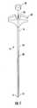
- FIG. 1is a perspective view of a surgical instrument for implanting a modular pedicle screw in accordance with the present invention illustrating a surgical shaft inserted within a cannula;
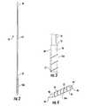
- FIG. 2is a perspective view of the surgical shaft in accordance with the present invention.
- FIG. 3is a partial view of the surgical shaft in accordance with the present invention.
- FIG. 4is a perspective view of the inner member of the modular pedicle bone screw
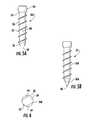
- FIG. 5Ais a perspective view of the outer sheath of the modular pedicle bone screw
- FIG. 5Bis a perspective view of the modular pedicle bone screw
- FIG. 6is a cross sectional view of the main body of the outer sheath of the modular pedicle bone screw
- FIG. 7illustrates the insertion of the surgical instrument for implanting a modular pedicle screw into the pedicle of the vertebra
- FIG. 8illustrates the removal of the cannula, exposing the surgical shaft
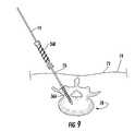
- FIG. 9illustrates the insertion of the bone screw shaft, using the surgical shaft as a guide
- FIG. 10illustrates the formation of the modular pedicle screw and removal of the surgical shaft from the patient
- FIG. 11is an illustrative embodiment of a kit in accordance with the present invention.
- FIG. 12is an alternative embodiment of a kit in accordance with the present invention.
- FIG. 13is an alternative embodiment of a kit in accordance with the present invention.
- a surgical instrument for implanting a modular pedicle screwreferred to generally as 10
- the surgical instrument for implanting a modular pedicle screw 10is preferably modeled after a standard Jamshidi style needle. Accordingly, the surgical instrument for implanting a modular pedicle screw 10 contains a first outer member, illustrated herein as a cannula 12 and a second inner member, illustrated herein as a modified trocar style surgical instrument shaft, referred to generally as trocar or surgical shaft 14 .
- the cannula 12contains a proximal end 16 , a distal end 18 , and an elongated main body 20 .
- the elongated main body 20is preferably rod shaped, having a generally hollow interior sized and shaped to receive the trocar or surgical shaft 14 .
- the cannula 12is co-axially aligned with the surgical shaft 14 to allow for the surgical shaft 14 to slide within the hollow interior.
- a handle 24attaches to the proximal end 16 via any means known to one of skill in the art, such as, but not limited to, threading or chemical fastening.
- the handle 24may be ergonomically designed to provide a gripping means for the user.
- the handle 24contains an opening 26 and a corresponding lumen (not illustrated).
- a detachable cap 28allows the surgical shaft 14 to be easy removed from the cannula 12 .
- the cannula 12 and the handle 24may be made of any suitable materials for use in surgical procedures, including but not limited to stainless steel, platinum, or plastics such as thermoplastics such as polyether ether ketone (PEEK), or combinations thereof.
- PEEKpolyether ether ketone
- the surgical shaft 14contains a first proximal end 30 , an opposing second distal end 32 , and an elongated main body 34 .
- the elongated main body 34is preferably rod shaped and solid, and sized to fit and slide within the hollow interior of the cannula 12 .
- the distal end 32 of the surgical shaft 14secures to an inner member of a modular pedicle bone screw 36 A.
- the inner member of a modular pedicle bone screw 36 Ais designed to secure to an outer bone screw sheath 36 B to form the modular pedicle bone screw, referred to in combination as 36 , see FIG. 5B .
- the inner member of a modular pedicle bone screw 36 Ais a solid elongated body, preferably cylindrical shape, with a sharp or pointed end.
- the distal end 32 of the surgical shaft 14contains a first member of a surgical shaft-inner pedicle bone screw member joint, illustrated herein as a locking taper 38 having tapered surfaces 40 .
- a locking taper 38having tapered surfaces 40 .
- the first member of a surgical shaft-inner pedicle bone screw member jointis frangibly attached to the distal end 32 of the modified surgical shaft 14 .
- the locking taperis designed to provide accurate alignment with and mate to a corresponding surface so that when mated, frictional forces are sufficient to prevent rotation with respect to one another and require considerable force to separate.
- the locking taper 38may include, but is not limited to a Morse locking taper or a Jarno locking taper, and may be designed to have a partial cone configuration or have a general cone shape having various angles of tapering.
- the locking taper 38is inserted into a second member of a surgical shaft-inner pedicle bone screw member joint, illustrated herein as a matching tapered socket 42 positioned within the surface 44 at the proximal end 45 of the inner member of a pedicle bone screw 36 A, see FIG. 4 . While the present invention describes the use of a locking taper and corresponding locking taper socket, other mechanisms to secure the surgical shaft to a portion of the screw may be used, including the threading and grooves or the use of male/female connectors.
- the distal end 46 of the inner member of a modular pedicle bone screw 36 Apreferably contains a pointed tip end 48 .
- the tip end 48 of the inner member of a modular pedicle bone screw 36 Aforms the pointed end of the surgical instrument for implanting a modular pedicle screw 10 , thus providing for the pointed tip to be useful in targeting an implant site, thereby forming a part of the actual implant.
- the pointed tip end 48forms the center of the pedicle bone screw 36 .
- the outer surface 50 of the inner member of a modular pedicle bone screw 36 Acontains a plurality of finely machined grooves 52 sized and shaped to interlock with a bone screw shaft 36 B, see FIG. 3 .
- the bone screw shaft 36 B of the pedicle bone screw 36comprises a proximal end 54 , a distal end 56 , and a bone screw shaft main body 58 .
- the bone screw shaft main body 58is illustrated having a generally elongated, tubular shape sized to fit over the inner member of the modular pedicle bone screw 36 A. Accordingly, the bone screw shaft main body 58 has a hollow or partially hollow interior 59 to allow for the inner member of the modular pedicle bone screw 36 A to slidably engage therein.
- the distal end 56has an opening 60 allowing the pointed end 48 of the inner member of the modular pedicle bone screw 36 A to extend upwardly.
- the interior surface 62contains threading 64 which engages with and secures to the grooves 52 of the inner member of the modular pedicle bone screw 36 A. Sliding the bone screw shaft 36 B over the inner member of the modular pedicle bone screw 36 A forms the solid bone screw 36 .
- a connector member 66which may be adapted to retain a screw set, locking cap, or spinal implant rod.
- the outer surface 68contains a plurality of threading 70 to secure the modular pedicle bone screw 36 to the portion of the body inserted therein.
- the present inventionwill further be defined by describing an illustrative example of method of use, see FIGS. 7-10 . While the surgical instrument for implanting a modular pedicle screw is described for use in spinal implantation, such use is not intended to be limiting. As such, the surgical instrument for implanting a modular pedicle screw in accordance with the present invention can be adapted and used in any surgical procedure requiring screw implantation.
- the surgical instrument for implanting a modular pedicle screw 10is shown inserted through the skin 72 of patient 74 .
- the patient 74is placed in a prone position according to standard surgical procedures.
- imaging or guidance technologysuch as fluoroscopy, is utilized and positioned in according to standard surgical procedures.
- the skin 72is marked and an incision 76 is made.
- the surgical instrument for implanting a modular pedicle screw 10is used under guidance to target and cannulate the target area, illustrated herein as the vertebral body 78 .
- the surgical instrument for implanting a modular pedicle screw 10is tapped to the desired depth within the vertebral body 78 . Once securely in position to the desired depth, the cannula 12 of the surgical instrument for implanting a modular pedicle screw 10 is removed. To perform such procedure, the cap 28 is removed from the handle 24 . The surgeon lifts the cannula 12 in a direction away from the patient 74 , see arrows 80 , FIG. 8 . Once the cannula 12 is removed, the surgical shaft 14 with the inner member of the modular pedicle bone screw 36 A remains embedded in the pedicle.
- the main body 34 of the surgical shaft 14is used as a guide for placing the bone screw shaft 36 B onto the inner member of the modular pedicle bone screw 36 A, thereby forming the modular pedicle bone screw 36 .
- the bone screw shaft 36 Bis cannulated to fit over and coaxially align with the already implanted inner member of the modular pedicle bone screw 36 A.
- the inner threading 64 positioned within the interior surface 62 of the bone screw shaft 36 Bsecures to and locks onto the finely machined grooves 52 on the outer surface of the inner member of the modular pedicle bone screw 36 A.
- all components with threadinghave the same thread pitch to allow for the inner and outer components to move as a single unit.
- a solid pedicle screw 36is formed and is comparable in strength to single, non-cannulated screws.
- the threading 70 on the outer surface 68 of the bone screw shaft 36 Bis screwed into place over the solid center thereby tapping the pedicle and allowing for removal as necessary as a standard screw.
- the implanted main body 34 of the surgical shaft 14may serve additional functions.
- the implanted main body 34 of the surgical shaft 14may be utilized as a guide through which a cannulated screw head may be placed, either uni-planar or multi-planar.
- the implanted main body 34 of the surgical shaft 14may also function as continued soft tissue retraction for visualization.
- the implanted main body 34 of the surgical shaft 14may be used as a guide through which standard instruments are used to distract or compress the space according to surgical indications.
- the implanted main body 34 of the surgical shaft 14is detached (such as through use of perforation within and around the surgical shaft perimeter, not shown or for example, constructing the detachable portion to have thinner diameter that breaks apart after a predetermined force, such as a predetermined bending force, is applied), leaving the pedicle screw implant 36 intact and in the proper, desired place.
- a predetermined forcesuch as a predetermined bending force
- the present inventionfurther contemplates the use of a kit including one or more of the following: pre-assembled surgical instrument for implanting a modular pedicle screw and/or a plurality of individual components.
- FIG. 11illustrates a first example of a kit in accordance with the present invention.
- the kit 82includes a sterilizable case having the contents of at least one cannula 12 , at least one surgical shaft with a locking member 38 unattached to an inner member of the pedicle screw 36 A, a plurality of different sized inner member of the pedicle screws 36 A, including 35 mm length 36 A 1 , 40 mm length 36 A 2 , 45 mm length 36 A 3 , and correspondingly sized bone screw shafts 36 B 1 , 36 B 2 , and 36 B 3 .
- the surgeonsecures the inner member of the modular pedicle bone screws 36 A to the appropriately sized surgical shaft with a locking member 38 and cannula 12 .
- FIG. 12illustrates a kit 86 having a sterilizable case 84 having the contents of at least one cannula 12 , a plurality of surgical shaft 14 1 , 14 2 , 14 3 with differently sized inner members of the pedicle screw 36 , and a plurality of and correspondingly sized bone screw shafts 36 B 1 36 B 2 , and 36 B 3 .
- FIG. 12illustrates a kit 86 having a sterilizable case 84 having the contents of at least one cannula 12 , a plurality of surgical shaft 14 1 , 14 2 , 14 3 with differently sized inner members of the pedicle screw 36 , and a plurality of and correspondingly sized bone screw shafts 36 B 1 36 B 2 , and 36 B 3 .
- FIG. 13illustrates a kit 88 having a sterilizable case 84 having the contents of a plurality of surgical instrument for implanting a modular pedicle screw 10 1 , 10 2 , 10 3 , each pre-assembled and having differently sized inner members of the pedicle screw 36 A, and a plurality of and correspondingly sized bone screw shafts 36 B 1 36 B 2 , and 36 B 3 .
Landscapes
- Health & Medical Sciences (AREA)
- Orthopedic Medicine & Surgery (AREA)
- Life Sciences & Earth Sciences (AREA)
- Surgery (AREA)
- Medical Informatics (AREA)
- Engineering & Computer Science (AREA)
- Biomedical Technology (AREA)
- Heart & Thoracic Surgery (AREA)
- Nuclear Medicine, Radiotherapy & Molecular Imaging (AREA)
- Molecular Biology (AREA)
- Animal Behavior & Ethology (AREA)
- General Health & Medical Sciences (AREA)
- Public Health (AREA)
- Veterinary Medicine (AREA)
- Neurology (AREA)
- Surgical Instruments (AREA)
Abstract
Description
Claims (11)
Priority Applications (2)
| Application Number | Priority Date | Filing Date | Title |
|---|---|---|---|
| US14/213,844US9763722B2 (en) | 2013-03-14 | 2014-03-14 | Surgical system, device, and method for implanting a surgical device without the use of a guide wire |
| US15/704,182US10575889B2 (en) | 2013-03-14 | 2017-09-14 | Surgical system, device, and method for implanting a surgical device without the use of a guide wire |
Applications Claiming Priority (2)
| Application Number | Priority Date | Filing Date | Title |
|---|---|---|---|
| US201361781860P | 2013-03-14 | 2013-03-14 | |
| US14/213,844US9763722B2 (en) | 2013-03-14 | 2014-03-14 | Surgical system, device, and method for implanting a surgical device without the use of a guide wire |
Related Child Applications (1)
| Application Number | Title | Priority Date | Filing Date |
|---|---|---|---|
| US15/704,182DivisionUS10575889B2 (en) | 2013-03-14 | 2017-09-14 | Surgical system, device, and method for implanting a surgical device without the use of a guide wire |
Publications (2)
| Publication Number | Publication Date |
|---|---|
| US20150127056A1 US20150127056A1 (en) | 2015-05-07 |
| US9763722B2true US9763722B2 (en) | 2017-09-19 |
Family
ID=50629000
Family Applications (2)
| Application Number | Title | Priority Date | Filing Date |
|---|---|---|---|
| US14/213,844Active2034-03-24US9763722B2 (en) | 2013-03-14 | 2014-03-14 | Surgical system, device, and method for implanting a surgical device without the use of a guide wire |
| US15/704,182ActiveUS10575889B2 (en) | 2013-03-14 | 2017-09-14 | Surgical system, device, and method for implanting a surgical device without the use of a guide wire |
Family Applications After (1)
| Application Number | Title | Priority Date | Filing Date |
|---|---|---|---|
| US15/704,182ActiveUS10575889B2 (en) | 2013-03-14 | 2017-09-14 | Surgical system, device, and method for implanting a surgical device without the use of a guide wire |
Country Status (2)
| Country | Link |
|---|---|
| US (2) | US9763722B2 (en) |
| WO (1) | WO2014153167A1 (en) |
Cited By (21)
| Publication number | Priority date | Publication date | Assignee | Title |
|---|---|---|---|---|
| US10575889B2 (en) | 2013-03-14 | 2020-03-03 | K2M, Inc. | Surgical system, device, and method for implanting a surgical device without the use of a guide wire |
| US10869722B2 (en) | 2016-11-02 | 2020-12-22 | Rochester Institute Of Technology | Method and fixture for guided pedicle screw placement |
| US11376134B1 (en) | 2020-11-05 | 2022-07-05 | Warsaw Orthopedic, Inc. | Dual expanding spinal implant, system, and method of use |
| US11395743B1 (en) | 2021-05-04 | 2022-07-26 | Warsaw Orthopedic, Inc. | Externally driven expandable interbody and related methods |
| US11517363B2 (en) | 2020-11-05 | 2022-12-06 | Warsaw Orthopedic, Inc. | Screw driver and complimentary screws |
| US11517443B2 (en) | 2020-11-05 | 2022-12-06 | Warsaw Orthopedic, Inc. | Dual wedge expandable implant, system and method of use |
| US11612499B2 (en) | 2021-06-24 | 2023-03-28 | Warsaw Orthopedic, Inc. | Expandable interbody implant |
| US11638653B2 (en) | 2020-11-05 | 2023-05-02 | Warsaw Orthopedic, Inc. | Surgery instruments with a movable handle |
| US11806250B2 (en) | 2018-02-22 | 2023-11-07 | Warsaw Orthopedic, Inc. | Expandable spinal implant system and method of using same |
| US11833059B2 (en) | 2020-11-05 | 2023-12-05 | Warsaw Orthopedic, Inc. | Expandable inter-body device, expandable plate system, and associated methods |
| US11850163B2 (en) | 2022-02-01 | 2023-12-26 | Warsaw Orthopedic, Inc. | Interbody implant with adjusting shims |
| US11963881B2 (en) | 2020-11-05 | 2024-04-23 | Warsaw Orthopedic, Inc. | Expandable inter-body device, system, and method |
| US12121453B2 (en) | 2020-11-05 | 2024-10-22 | Warsaw Orthopedic, Inc. | Dual wedge expandable implant with eyelets, system, and method of use |
| US12171439B2 (en) | 2020-11-05 | 2024-12-24 | Warsaw Orthopedic, Inc. | Protected drill |
| US12239544B2 (en) | 2020-11-05 | 2025-03-04 | Warsaw Orthopedic, Inc. | Rhomboid shaped implants |
| US12268402B2 (en) | 2020-04-09 | 2025-04-08 | Biedermann Technologies Gmbh & Co. Kg | Surgical instrument |
| US12268614B2 (en) | 2021-06-24 | 2025-04-08 | Warsaw Orthopedic, Inc. | Interbody implant with adjusting shims |
| US12295865B2 (en) | 2021-06-24 | 2025-05-13 | Warsaw Orthopedic, Inc. | Expandable interbody implant and corresponding inserter |
| US12318308B2 (en) | 2020-11-05 | 2025-06-03 | Warsaw Orthopedic, Inc. | Dual expandable inter-body device |
| US12414863B2 (en) | 2021-06-24 | 2025-09-16 | Warsaw Orthopedic, Inc. | Expandable interbody implant and corresponding surgical tool |
| US12440349B2 (en) | 2022-02-04 | 2025-10-14 | Warsaw Orthopedic, Inc. | Expandable interbody implant and breakoff screw |
Families Citing this family (4)
| Publication number | Priority date | Publication date | Assignee | Title |
|---|---|---|---|---|
| US9993276B2 (en)* | 2013-03-15 | 2018-06-12 | Innovision, Inc. | Bone screws and methods of use thereof |
| EP3482583B1 (en)* | 2016-07-06 | 2022-10-12 | Telefonaktiebolaget LM Ericsson (PUBL) | Transfer of a monitoring responsibility |
| US11950817B2 (en) | 2016-12-29 | 2024-04-09 | Sinnov, Llc | Two-part screw systems and methods for implanting same |
| US11666367B2 (en)* | 2018-05-30 | 2023-06-06 | Tushar Goradia | Guidance apparatus for implantation into bone and related methods of use |
Citations (17)
| Publication number | Priority date | Publication date | Assignee | Title |
|---|---|---|---|---|
| US4013071A (en)* | 1974-11-11 | 1977-03-22 | Lior Rosenberg | Fasteners particularly useful as orthopedic screws |
| US5098435A (en)* | 1990-11-21 | 1992-03-24 | Alphatec Manufacturing Inc. | Cannula |
| US5667513A (en)* | 1995-06-07 | 1997-09-16 | Smith & Nephew Dyonics Inc. | Soft tissue anchor delivery apparatus |
| US6033406A (en)* | 1992-03-17 | 2000-03-07 | Sdgi Holdings, Inc. | Method for subcutaneous suprafascial pedicular internal fixation |
| US20050143734A1 (en)* | 1996-11-12 | 2005-06-30 | Cachia Victor V. | Bone fixation system with radially extendable anchor |
| US6951561B2 (en)* | 2003-05-06 | 2005-10-04 | Triage Medical, Inc. | Spinal stabilization device |
| US20060089647A1 (en)* | 2004-08-20 | 2006-04-27 | Culbert Brad S | Method and apparatus for delivering an agent |
| US20060149245A1 (en)* | 2004-06-09 | 2006-07-06 | Spinal Generations, Llc | Bone fixation system |
| US20070213732A1 (en)* | 2006-03-13 | 2007-09-13 | The Johns Hopkins University | Orthopedic Screw System |
| US20070233066A1 (en)* | 2006-02-17 | 2007-10-04 | Sdgi Holdings, Inc. | Dorsal adjusting spinal connector assembly |
| US20090062864A1 (en)* | 2007-08-31 | 2009-03-05 | Steven Ludwig | Offset connection bone anchor assembly |
| US7780706B2 (en) | 2005-04-27 | 2010-08-24 | Trinity Orthopedics, Llc | Mono-planar pedicle screw method, system and kit |
| US20100280558A1 (en)* | 2008-08-05 | 2010-11-04 | The University Of Toledo | Pedicle screw assembly having a retractable screw tip for facilitating the securement of the pedicle screw assembly to a spinal vertebra |
| US20100312292A1 (en)* | 2001-10-18 | 2010-12-09 | Orthoip, Llc | Lagwire system and method for the fixation of bone fractures |
| US7938848B2 (en)* | 2004-06-09 | 2011-05-10 | Life Spine, Inc. | Spinal fixation system |
| US20120239052A1 (en)* | 2011-03-14 | 2012-09-20 | Aesculap Ag | Surgical k-wire and surgical screw system |
| US8388660B1 (en)* | 2006-08-01 | 2013-03-05 | Samy Abdou | Devices and methods for superior fixation of orthopedic devices onto the vertebral column |
Family Cites Families (5)
| Publication number | Priority date | Publication date | Assignee | Title |
|---|---|---|---|---|
| US5478342A (en)* | 1994-06-30 | 1995-12-26 | Spinetech, Inc. | Reversible bone screw lock |
| US6471707B1 (en)* | 2001-05-11 | 2002-10-29 | Biomet | Bone screw having bioresorbable proximal shaft portion |
| US6981976B1 (en)* | 2002-05-13 | 2006-01-03 | Biomet, Inc. | Method and apparatus for inserting and countersinking a modular screw |
| ES2552380T3 (en)* | 2009-07-01 | 2015-11-27 | Biedermann Technologies Gmbh & Co. Kg | Instruments for use with a bone anchor with closure element |
| WO2014153167A1 (en) | 2013-03-14 | 2014-09-25 | The Raph Life, Llc | Surgical system device without the use of a guide wire |
- 2014
- 2014-03-14WOPCT/US2014/029385patent/WO2014153167A1/enactiveApplication Filing
- 2014-03-14USUS14/213,844patent/US9763722B2/enactiveActive
- 2017
- 2017-09-14USUS15/704,182patent/US10575889B2/enactiveActive
Patent Citations (17)
| Publication number | Priority date | Publication date | Assignee | Title |
|---|---|---|---|---|
| US4013071A (en)* | 1974-11-11 | 1977-03-22 | Lior Rosenberg | Fasteners particularly useful as orthopedic screws |
| US5098435A (en)* | 1990-11-21 | 1992-03-24 | Alphatec Manufacturing Inc. | Cannula |
| US6033406A (en)* | 1992-03-17 | 2000-03-07 | Sdgi Holdings, Inc. | Method for subcutaneous suprafascial pedicular internal fixation |
| US5667513A (en)* | 1995-06-07 | 1997-09-16 | Smith & Nephew Dyonics Inc. | Soft tissue anchor delivery apparatus |
| US20050143734A1 (en)* | 1996-11-12 | 2005-06-30 | Cachia Victor V. | Bone fixation system with radially extendable anchor |
| US20100312292A1 (en)* | 2001-10-18 | 2010-12-09 | Orthoip, Llc | Lagwire system and method for the fixation of bone fractures |
| US6951561B2 (en)* | 2003-05-06 | 2005-10-04 | Triage Medical, Inc. | Spinal stabilization device |
| US20060149245A1 (en)* | 2004-06-09 | 2006-07-06 | Spinal Generations, Llc | Bone fixation system |
| US7938848B2 (en)* | 2004-06-09 | 2011-05-10 | Life Spine, Inc. | Spinal fixation system |
| US20060089647A1 (en)* | 2004-08-20 | 2006-04-27 | Culbert Brad S | Method and apparatus for delivering an agent |
| US7780706B2 (en) | 2005-04-27 | 2010-08-24 | Trinity Orthopedics, Llc | Mono-planar pedicle screw method, system and kit |
| US20070233066A1 (en)* | 2006-02-17 | 2007-10-04 | Sdgi Holdings, Inc. | Dorsal adjusting spinal connector assembly |
| US20070213732A1 (en)* | 2006-03-13 | 2007-09-13 | The Johns Hopkins University | Orthopedic Screw System |
| US8388660B1 (en)* | 2006-08-01 | 2013-03-05 | Samy Abdou | Devices and methods for superior fixation of orthopedic devices onto the vertebral column |
| US20090062864A1 (en)* | 2007-08-31 | 2009-03-05 | Steven Ludwig | Offset connection bone anchor assembly |
| US20100280558A1 (en)* | 2008-08-05 | 2010-11-04 | The University Of Toledo | Pedicle screw assembly having a retractable screw tip for facilitating the securement of the pedicle screw assembly to a spinal vertebra |
| US20120239052A1 (en)* | 2011-03-14 | 2012-09-20 | Aesculap Ag | Surgical k-wire and surgical screw system |
Non-Patent Citations (1)
| Title |
|---|
| Shaft. Dictionary.com. Dictionary.com Unabridged. Random House, Inc. http://www.dictionary.com/browse/shaft (accessed: Feb. 21, 2017).* |
Cited By (27)
| Publication number | Priority date | Publication date | Assignee | Title |
|---|---|---|---|---|
| US10575889B2 (en) | 2013-03-14 | 2020-03-03 | K2M, Inc. | Surgical system, device, and method for implanting a surgical device without the use of a guide wire |
| US10869722B2 (en) | 2016-11-02 | 2020-12-22 | Rochester Institute Of Technology | Method and fixture for guided pedicle screw placement |
| US11806250B2 (en) | 2018-02-22 | 2023-11-07 | Warsaw Orthopedic, Inc. | Expandable spinal implant system and method of using same |
| US12036132B2 (en) | 2018-02-22 | 2024-07-16 | Warsaw Orthopedic, Inc. | Expandable spinal implant system and method of using same |
| US12268402B2 (en) | 2020-04-09 | 2025-04-08 | Biedermann Technologies Gmbh & Co. Kg | Surgical instrument |
| US12171439B2 (en) | 2020-11-05 | 2024-12-24 | Warsaw Orthopedic, Inc. | Protected drill |
| US12053392B2 (en) | 2020-11-05 | 2024-08-06 | Warsaw Orthopedic, Inc. | Expandable inter-body device, expandable plate system, and associated methods |
| US12364529B2 (en) | 2020-11-05 | 2025-07-22 | Warsaw Orthopedic, Inc. | Expandable inter-body device, system, and method |
| US11617658B2 (en) | 2020-11-05 | 2023-04-04 | Warsaw Orthopedic, Inc. | Expandable inter-body device, system and method |
| US11638653B2 (en) | 2020-11-05 | 2023-05-02 | Warsaw Orthopedic, Inc. | Surgery instruments with a movable handle |
| US11517443B2 (en) | 2020-11-05 | 2022-12-06 | Warsaw Orthopedic, Inc. | Dual wedge expandable implant, system and method of use |
| US11833059B2 (en) | 2020-11-05 | 2023-12-05 | Warsaw Orthopedic, Inc. | Expandable inter-body device, expandable plate system, and associated methods |
| US12318308B2 (en) | 2020-11-05 | 2025-06-03 | Warsaw Orthopedic, Inc. | Dual expandable inter-body device |
| US11963881B2 (en) | 2020-11-05 | 2024-04-23 | Warsaw Orthopedic, Inc. | Expandable inter-body device, system, and method |
| US11969196B2 (en) | 2020-11-05 | 2024-04-30 | Warsaw Orthopedic, Inc. | Expandable inter-body device, system, and method |
| US11517363B2 (en) | 2020-11-05 | 2022-12-06 | Warsaw Orthopedic, Inc. | Screw driver and complimentary screws |
| US11564724B2 (en) | 2020-11-05 | 2023-01-31 | Warsaw Orthopedic, Inc. | Expandable inter-body device, system and method |
| US12121453B2 (en) | 2020-11-05 | 2024-10-22 | Warsaw Orthopedic, Inc. | Dual wedge expandable implant with eyelets, system, and method of use |
| US11376134B1 (en) | 2020-11-05 | 2022-07-05 | Warsaw Orthopedic, Inc. | Dual expanding spinal implant, system, and method of use |
| US12239544B2 (en) | 2020-11-05 | 2025-03-04 | Warsaw Orthopedic, Inc. | Rhomboid shaped implants |
| US11395743B1 (en) | 2021-05-04 | 2022-07-26 | Warsaw Orthopedic, Inc. | Externally driven expandable interbody and related methods |
| US12268614B2 (en) | 2021-06-24 | 2025-04-08 | Warsaw Orthopedic, Inc. | Interbody implant with adjusting shims |
| US12295865B2 (en) | 2021-06-24 | 2025-05-13 | Warsaw Orthopedic, Inc. | Expandable interbody implant and corresponding inserter |
| US11612499B2 (en) | 2021-06-24 | 2023-03-28 | Warsaw Orthopedic, Inc. | Expandable interbody implant |
| US12414863B2 (en) | 2021-06-24 | 2025-09-16 | Warsaw Orthopedic, Inc. | Expandable interbody implant and corresponding surgical tool |
| US11850163B2 (en) | 2022-02-01 | 2023-12-26 | Warsaw Orthopedic, Inc. | Interbody implant with adjusting shims |
| US12440349B2 (en) | 2022-02-04 | 2025-10-14 | Warsaw Orthopedic, Inc. | Expandable interbody implant and breakoff screw |
Also Published As
| Publication number | Publication date |
|---|---|
| US10575889B2 (en) | 2020-03-03 |
| US20150127056A1 (en) | 2015-05-07 |
| US20180008331A1 (en) | 2018-01-11 |
| WO2014153167A1 (en) | 2014-09-25 |
Similar Documents
| Publication | Publication Date | Title |
|---|---|---|
| US10575889B2 (en) | Surgical system, device, and method for implanting a surgical device without the use of a guide wire | |
| US9241722B2 (en) | Surgical pin guide and methods of use | |
| AU2008281445B2 (en) | System and method for insertion of flexible spinal stabilization element | |
| US7927360B2 (en) | Spinal anchor assemblies having extended receivers | |
| US7905907B2 (en) | Internal structure stabilization system for spanning three or more structures | |
| US7967826B2 (en) | Connector transfer tool for internal structure stabilization systems | |
| US8734452B2 (en) | Guidance system,tools and devices for spinal fixation | |
| US9254149B2 (en) | Spinal fixation method and apparatus | |
| US20130245691A1 (en) | Systems and methods for spinal fixation | |
| US20110190822A1 (en) | Internal Structure Stabilization System for Spanning Three or More Structures | |
| US20130012955A1 (en) | System and Method for Pedicle Screw Placement in Vertebral Alignment | |
| US20090093851A1 (en) | Transfacet-Pedicle Locking Screw Fixation of Lumbar Motion Segment | |
| CN101511288A (en) | Systems and methods for spinal fixation | |
| US20200146698A1 (en) | Thread Forming Jamshidi Assembly | |
| US20200038073A1 (en) | Percutaneous Transverse Connector System | |
| US20130150864A1 (en) | Surgical instrument and method | |
| US12076059B2 (en) | Pedicle screw retractor system and method of use for spine surgery | |
| US8956284B2 (en) | Minimally invasive retractor and posted screw | |
| US20200022734A1 (en) | Apparatus, system, and method for spinal vertebrae stabilization |
Legal Events
| Date | Code | Title | Description |
|---|---|---|---|
| AS | Assignment | Owner name:THE RAPH LIFE, LLC, GEORGIA Free format text:ASSIGNMENT OF ASSIGNORS INTEREST;ASSIGNOR:ROYBAL, RAPHAEL;REEL/FRAME:032447/0566 Effective date:20140314 | |
| AS | Assignment | Owner name:K2M, VIRGINIA Free format text:ASSIGNMENT OF ASSIGNORS INTEREST;ASSIGNOR:THE RAPH LIFE LLC;REEL/FRAME:033857/0239 Effective date:20140601 | |
| AS | Assignment | Owner name:K2M, INC., VIRGINIA Free format text:CORRECTIVE ASSIGNMENT TO CORRECT THE ASSIGNEE'S NAME PREVIOUSLY RECORDED AT REEL: 033857 FRAME: 0239. ASSIGNOR(S) HEREBY CONFIRMS THE ASSIGNMENT;ASSIGNOR:THE RAPH LIFE, LLC;REEL/FRAME:033950/0686 Effective date:20140928 | |
| AS | Assignment | Owner name:SILICON VALLEY BANK, AS ADMINISTRATIVE AGENT, CALIFORNIA Free format text:SECOND AMENDMENT TO PATENT SECURITY AGREEMENT;ASSIGNORS:K2M, INC.;K2M HOLDINGS, INC.;K2M UK LIMITED;REEL/FRAME:037091/0221 Effective date:20151029 Owner name:SILICON VALLEY BANK, AS ADMINISTRATIVE AGENT, CALI Free format text:SECOND AMENDMENT TO PATENT SECURITY AGREEMENT;ASSIGNORS:K2M, INC.;K2M HOLDINGS, INC.;K2M UK LIMITED;REEL/FRAME:037091/0221 Effective date:20151029 | |
| AS | Assignment | Owner name:SILICON VALLEY BANK, AS ADMINISTRATIVE AGENT, CALIFORNIA Free format text:THIRD AMENDMENT TO PATENT SECURITY AGREEMENT;ASSIGNORS:K2M, INC.;K2M HOLDINGS, INC.;K2M UK LIMITED;REEL/FRAME:039627/0659 Effective date:20160808 Owner name:SILICON VALLEY BANK, AS ADMINISTRATIVE AGENT, CALI Free format text:THIRD AMENDMENT TO PATENT SECURITY AGREEMENT;ASSIGNORS:K2M, INC.;K2M HOLDINGS, INC.;K2M UK LIMITED;REEL/FRAME:039627/0659 Effective date:20160808 | |
| STCF | Information on status: patent grant | Free format text:PATENTED CASE | |
| AS | Assignment | Owner name:K2M UK LIMITED, UNITED KINGDOM Free format text:RELEASE BY SECURED PARTY;ASSIGNOR:SILICON VALLEY BANK;REEL/FRAME:047496/0001 Effective date:20181109 Owner name:K2M, INC., VIRGINIA Free format text:RELEASE BY SECURED PARTY;ASSIGNOR:SILICON VALLEY BANK;REEL/FRAME:047496/0001 Effective date:20181109 Owner name:K2M HOLDINGS, INC., VIRGINIA Free format text:RELEASE BY SECURED PARTY;ASSIGNOR:SILICON VALLEY BANK;REEL/FRAME:047496/0001 Effective date:20181109 | |
| MAFP | Maintenance fee payment | Free format text:PAYMENT OF MAINTENANCE FEE, 4TH YEAR, LARGE ENTITY (ORIGINAL EVENT CODE: M1551); ENTITY STATUS OF PATENT OWNER: LARGE ENTITY Year of fee payment:4 | |
| FEPP | Fee payment procedure | Free format text:MAINTENANCE FEE REMINDER MAILED (ORIGINAL EVENT CODE: REM.); ENTITY STATUS OF PATENT OWNER: LARGE ENTITY | |
| AS | Assignment | Owner name:ANKURA TRUST COMPANY, LLC, AS COLLATERAL AGENT, CONNECTICUT Free format text:PATENT SECURITY AGREEMENT;ASSIGNORS:K2M, INC.;VB SPINE US OPCO LLC;VB SPINE LLC;REEL/FRAME:071682/0116 Effective date:20250616 |