US9763629B2 - Medical device with context-specific interfaces - Google Patents
Medical device with context-specific interfacesDownload PDFInfo
- Publication number
- US9763629B2 US9763629B2US14/535,534US201414535534AUS9763629B2US 9763629 B2US9763629 B2US 9763629B2US 201414535534 AUS201414535534 AUS 201414535534AUS 9763629 B2US9763629 B2US 9763629B2
- Authority
- US
- United States
- Prior art keywords
- medical device
- area
- additional parameters
- vital signs
- user
- Prior art date
- Legal status (The legal status is an assumption and is not a legal conclusion. Google has not performed a legal analysis and makes no representation as to the accuracy of the status listed.)
- Active, expires
Links
Images


Classifications
- G—PHYSICS
- G16—INFORMATION AND COMMUNICATION TECHNOLOGY [ICT] SPECIALLY ADAPTED FOR SPECIFIC APPLICATION FIELDS
- G16H—HEALTHCARE INFORMATICS, i.e. INFORMATION AND COMMUNICATION TECHNOLOGY [ICT] SPECIALLY ADAPTED FOR THE HANDLING OR PROCESSING OF MEDICAL OR HEALTHCARE DATA
- G16H40/00—ICT specially adapted for the management or administration of healthcare resources or facilities; ICT specially adapted for the management or operation of medical equipment or devices
- G16H40/60—ICT specially adapted for the management or administration of healthcare resources or facilities; ICT specially adapted for the management or operation of medical equipment or devices for the operation of medical equipment or devices
- G16H40/63—ICT specially adapted for the management or administration of healthcare resources or facilities; ICT specially adapted for the management or operation of medical equipment or devices for the operation of medical equipment or devices for local operation
- A—HUMAN NECESSITIES
- A61—MEDICAL OR VETERINARY SCIENCE; HYGIENE
- A61B—DIAGNOSIS; SURGERY; IDENTIFICATION
- A61B5/00—Measuring for diagnostic purposes; Identification of persons
- A61B5/74—Details of notification to user or communication with user or patient; User input means
- A61B5/742—Details of notification to user or communication with user or patient; User input means using visual displays
- A—HUMAN NECESSITIES
- A61—MEDICAL OR VETERINARY SCIENCE; HYGIENE
- A61B—DIAGNOSIS; SURGERY; IDENTIFICATION
- A61B5/00—Measuring for diagnostic purposes; Identification of persons
- A61B5/74—Details of notification to user or communication with user or patient; User input means
- A61B5/7475—User input or interface means, e.g. keyboard, pointing device, joystick
- G06F19/3406—
- G—PHYSICS
- G16—INFORMATION AND COMMUNICATION TECHNOLOGY [ICT] SPECIALLY ADAPTED FOR SPECIFIC APPLICATION FIELDS
- G16H—HEALTHCARE INFORMATICS, i.e. INFORMATION AND COMMUNICATION TECHNOLOGY [ICT] SPECIALLY ADAPTED FOR THE HANDLING OR PROCESSING OF MEDICAL OR HEALTHCARE DATA
- G16H10/00—ICT specially adapted for the handling or processing of patient-related medical or healthcare data
- G16H10/60—ICT specially adapted for the handling or processing of patient-related medical or healthcare data for patient-specific data, e.g. for electronic patient records
- G—PHYSICS
- G16—INFORMATION AND COMMUNICATION TECHNOLOGY [ICT] SPECIALLY ADAPTED FOR SPECIFIC APPLICATION FIELDS
- G16H—HEALTHCARE INFORMATICS, i.e. INFORMATION AND COMMUNICATION TECHNOLOGY [ICT] SPECIALLY ADAPTED FOR THE HANDLING OR PROCESSING OF MEDICAL OR HEALTHCARE DATA
- G16H15/00—ICT specially adapted for medical reports, e.g. generation or transmission thereof
- G—PHYSICS
- G16—INFORMATION AND COMMUNICATION TECHNOLOGY [ICT] SPECIALLY ADAPTED FOR SPECIFIC APPLICATION FIELDS
- G16H—HEALTHCARE INFORMATICS, i.e. INFORMATION AND COMMUNICATION TECHNOLOGY [ICT] SPECIALLY ADAPTED FOR THE HANDLING OR PROCESSING OF MEDICAL OR HEALTHCARE DATA
- G16H50/00—ICT specially adapted for medical diagnosis, medical simulation or medical data mining; ICT specially adapted for detecting, monitoring or modelling epidemics or pandemics
- G16H50/30—ICT specially adapted for medical diagnosis, medical simulation or medical data mining; ICT specially adapted for detecting, monitoring or modelling epidemics or pandemics for calculating health indices; for individual health risk assessment
- G—PHYSICS
- G16—INFORMATION AND COMMUNICATION TECHNOLOGY [ICT] SPECIALLY ADAPTED FOR SPECIFIC APPLICATION FIELDS
- G16H—HEALTHCARE INFORMATICS, i.e. INFORMATION AND COMMUNICATION TECHNOLOGY [ICT] SPECIALLY ADAPTED FOR THE HANDLING OR PROCESSING OF MEDICAL OR HEALTHCARE DATA
- G16H40/00—ICT specially adapted for the management or administration of healthcare resources or facilities; ICT specially adapted for the management or operation of medical equipment or devices
- G16H40/60—ICT specially adapted for the management or administration of healthcare resources or facilities; ICT specially adapted for the management or operation of medical equipment or devices for the operation of medical equipment or devices
- G16H40/67—ICT specially adapted for the management or administration of healthcare resources or facilities; ICT specially adapted for the management or operation of medical equipment or devices for the operation of medical equipment or devices for remote operation
Definitions
- a medical devicein another aspect, includes: a processor; a display; and memory encoding instructions that, when executed by the processor, cause the processor to create an interface on the display, the interface including: a vital signs area programmed to display data associated with a plurality of vital signs for a patient; and an additional parameters area programmed to capture one or more additional parameters associated with the vital signs displayed in the vital signs area.
- FIG. 1illustrates a block diagram of a wireless ambulatory care system.
- FIG. 2illustrates an example medical device of the system of FIG. 1 .
- FIG. 4illustrates an example login and profile selection interface for the medical device of FIG. 3 .
- FIG. 7illustrates another view of the interface of FIG. 4 .
- FIG. 8illustrates an example vital signs interface for the medical device of FIG. 3 .
- FIG. 9illustrates an example interface for the medical device of FIG. 3 .
- FIG. 10illustrates another view of the interface of FIG. 9 .
- FIG. 11illustrates another view of the interface of FIG. 9 .
- FIG. 12illustrates another view of the interface of FIG. 9 .
- FIG. 15is a block diagram illustrating physical components of a computing device with which examples and embodiments of the disclosure can be practiced.
- Examples of ambulatory care environmentscan include hospitals, clinics, managed care facilities, and other locations where medical care is provided. Medical personnel in ambulatory care environments can utilize vital signs monitoring devices, vital signs displays, personal computing devices and electronic medical record access portals. Medical staff and providers often need to record a patient's vital signs and enter those vital signs into the patient's electronic medical record. Currently, providers must perform vital signs measurements, remember the measurements, and then enter those measurements into one or more computing devices which may or may not be directly linked to the patient's electronic medical record.
- FIG. 1illustrates a block diagram of an example wireless ambulatory care network 100 .
- the example network 100includes medical devices 103 and 104 , wireless computing devices 108 and 109 , and communication network 110 .
- the example network 100can include more or fewer medical devices 103 and 104 .
- the example networkcan include more or fewer wireless computing devices 108 and 109 .
- the communication network 110can be a wireless network, such as WiFi, Bluetooth, Zigbee, Ant, Z-Wave, etc.
- the one or more medical devices 103 and 104can include one or more vital signs measurement components.
- the medical devices 103can include, for example, a thermometer, a heart rate monitor, a pulse oximeter, a non-invasive blood pressure monitor, and a respiration rate monitor.
- one or more vital signs measurement componentsare wirelessly linked to the medical devices 103 and 104 and can transmit measurements to the medical devices 103 and 104 .
- Example computing components of medical devices 103 and 104are shown and described in more detail with reference to FIG. 15 , below.
- the one or more wireless computing devices 108 and 109can be smart phones, tablet computers, personal digital assistants, laptop computers, and desktop computers, which can optionally be mounted on portable carts.
- Example computing components of the one or more wireless computing devices 108 and 109are shown and described in more detail with reference to FIG. 15 , below.
- the use of less complicated wireless computing devices 108 and 109such as heart rate monitors, pulse oximeters, etc., is also contemplated by this document.
- FIG. 2illustrates one example of the medical device 105 .
- the medical device 105is shown on a mobile cart, and the medical device 105 is programmed to provide the functionalities described herein.
- the medical device 105includes a user interface, such as a touch screen, and includes the ability to execute multiple workflows or profiles.
- the medical devices 105 and 106 in FIGS. 2 and 3are the medical device 103 or 104 shown in, and described with reference to, FIG. 1 .
- Other embodimentscan include more or fewer components than those shown in FIG. 2 , or include different components that accomplish the same or a similar function.
- the medical device 105is able to operate within one or more profiles.
- a profileis a series of one or more tasks that a user of the medical device 105 performs.
- the medical device 105provides functionality suitable for assisting the user in performing the profile.
- the medical device 105operates within different profiles, the medical device 105 provides different functionality.
- the medical device 105When the medical device 105 is manufactured, the medical device 105 is configured to be able to operate within one or more profiles. After the medical device 105 is manufactured, the medical device 105 can be reconfigured to operate within one or more additional profiles. In this way, a user can adapt the medical device 105 for use in different profiles as needed.
- the medical device 105operates within various profiles.
- the medical device 105can operate within a monitoring profile or a non-monitoring profile.
- Example types of non-monitoring profilesinclude, but are not limited to, a spot check profile and an office profile.
- An example of a monitoring profileincludes, but is not limited to, an intervals profile.
- FIG. 3An additional example of the medical device 106 is shown in FIG. 3 .
- the medical device 106is similar to that of the medical device 105 described above.
- the medical device 106is mounted on a wall.
- the medical device 106is programmed in a manner similar to that described above to monitor physiological parameters of a patient.
- the medical device 106is a stand-alone device, which can mean that is not part of a mobile cart and it is not part of a wall-mounted station.
- the medical devices 104 , 105 , 106are computing devices that have been programmed to perform special, complex functions. These specially-programmed devices function to manipulate and provide data to the users in an improved form factor and with greater efficiency.
- the medical devices 104 , 105 , 106are specially programmed to provide the user with an improved interface during initial use of the devices. This allows the user to more efficiently select a profile for controlling the functionality of the device.
- the medical devices 104 , 105 , 106are specially programmed to assist the users once vital signs information is captured from the patients.
- the devicesare programmed to more efficiently and easily capture additional contextual information that is needed when saving vital signs data to a permanent record, such as an EMR record. This is accomplished using an interface that is more intuitive and robust.
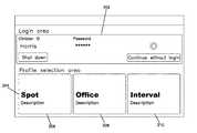
- FIGS. 4-8an example interface 200 for allowing a user to login to and select a profile for the medical devices 104 , 105 , 106 is shown.
- the interface 200includes a login area 202 and a profile selection area 204 .
- the login area 202collects information to assist in the identification of the user. This information includes a clinician identifier (ID) and a password. In other examples, different information can be collected, such as a user name or badge number. Any other identification information can also be captured as desired.
- the usercan enter the identification information into the device using an input device such as a keyboard, touchscreen, mouse, scanner, etc.
- the deviceconfirms the credentials. This can be completed locally (i.e., by the device itself) and/or by accessing information on the network 110 .
- the profile selection area 204generally provides information about the different profiles that can be implemented by the device. In the example given, the device can operate using one of three profiles: spot, office, or interval.
- Each of the profilesincludes a separate area 206 , 208 , 210 that allows for contextual information to be provided about that profile.
- the spot area 206includes the name of the profile and a description of what is accomplished using the profile. This description can include such information as: (i) data acquisition—what vital signs data is collected for the profile; (ii) data retention—how that vital signs data is stored, such as in duration; (iii) patient identification retention—how patient-specific information is retained by the device; etc.
- the descriptionis a textual string (e.g., a series of sentences and/or one or more paragraphs) that describe, in prose form, how the profile functions.
- the spot profileis a non-monitoring profile
- the descriptioncan provide information to the user such as: a customized label describing the facility's preferred term for the workflow such as “Rounds”, “Vitals”, “Observations”, a customized description such as, “For single-reading use on multiple patients,” or “Multiple patients per round”, and a customized icon to provide visual recognition of the workflow.
- Similar languagecan be provided in the office area 208 (e.g., a customized label describing the facility's preferred term for the workflow such as “Vitals”, “Exams”, or “Readings”, a customized description such as, “For use on routine exams”, and a customized icon to provide visual recognition of the workflow) and interval area 210 (e.g., a customized label describing the facility's preferred term for the workflow such as “Interval Monitoring”, “Intervals”, “Bedside Observations”, a customized description such as, “For multiple readings on single patients” or “Single patient monitoring”, and a customized icon to provide visual recognition of the workflow) to allow the user to make an educated decision on how to configure the device before the device is used.
- the usercan select one of the areas 206 , 208 , 210 as desired using an input device (e.g., keyboard, mouse or touch) to start the device in that profile.
- an input devicee.g., keyboard, mouse or touch
- the usermust identify the patient.
- a box 211is presented to the user, and the user can identify the patient using various methods, such as by scanning a patient identification tag.
- This interface 220can be used to capture vital signs information, such as that shown in FIGS. 2-3 .
- profile areasare configurable depending on the type of device and/or the type of use for the device. For example, a particular facility (e.g., hospital or clinic) can tailor the profiles to those used at that facility, as well as tailor the description of those profiles to use vernacular that is more easily understood at the given facility. In this manner, the user is provided with the relevant profiles, and each profile area provides additional context so that the user can make the proper selection of the desired profile before vital capture.
- a particular facilitye.g., hospital or clinic
- the login area 202includes a control (“Continue without login”) that allows a user to use the medical device without providing login credentials.
- a controlContinuous without login
- Such functionalitycould be used, for example, in an emergency situation where the time required to provide those credentials could compromise patient health.
- the medical deviceis accessed in this manner, some of the functionality of the medical device can be limited or otherwise modified.
- the medical devicemay not allow any vital signs data to be recorded to an EMR until the user provides the necessary credentials. Other configurations are possible.
- the additional datacan include parameters associated with the vitals data that is collected and stored by the medical device.
- this datainclude inputs for text, integers, decimals, lists, and modifiers (a custom input becomes a modifier if an association is established between the input and a parameter on the device during configuration). All custom inputs can have input ranges specified and validation rules established.
- Example custom inputsinclude, without limitation, Capillary Refill Time (CRT), Glucose, Glasgow Coma Score, Urine Output, Cuff Size, O2 Flow Rate, O2 concentration, Measurement Site, etc.
- CTRCapillary Refill Time
- GlucoseGlasgow Coma Score
- Urine OutputCuff Size
- O2 Flow RateO2 concentration
- Measurement Siteetc.
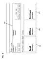
- the interface 320is shown displaying captured vital signs data, including NIBP, Pulse Rate, SpO2, and Temperature. As noted, these are only examples, and other vital signs data can also be captured and displayed.
- the userselects a next button 328 to record the vital signs data to, for example, an EMR.
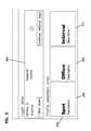
- FIG. 10shows additional parameters areas 322 , 324 , 326 that are displayed when the user selects the next button 328 on the interface 320 .
- These additional parameter areas 322 , 324 , 326are used to capture further information that is needed when recording the vital signs data to the EMR.
- the additional parameter area 322records an Early Warning Score for the patient. The user selects between Scores 1-3.
- the additional parameter areas 324 , 326capture other parameters, such as CRT, Pain, Respirations, White Cell Count, Respiratory Distress, and/or Conscious Level. While three additional parameters are shown, more or fewer can be captured. For example, the additional parameters that are obtained can be tailored to the vital signs information that is captured by the device and shown on the interface 320 .
- the next button 328become active, as shown in FIG. 11 .
- the usermust provide each additional parameter or affirmatively skip one or more of the parameters (see FIG. 14 ) before the next button 328 become active.
- buttons 328Once the next button 328 is selected, a summary of the additional parameters is provided to the user on an interface 332 at FIG. 12 . This allows the user to review the additional parameter information for accuracy. Assuming everything is correct, the user can select the button 330 to store the additional parameters.
- the interface 320is again shown.
- the next button 328is removed, and a save button 342 is provided.
- the save button 342causes the vital signs data and additional parameters to be saved, for example, locally and/or to an EMR record across the network 110 .
- the additional parameter areas 322 , 324 , 326can also include skip buttons that allow the user to avoid providing one or more of the additional parameters. If a skip button is pressed, the user is presented with an interface 350 shown in FIG. 14 . The example interface 350 indicates that the particular facility requires that the additional parameter be recorded. If the user selects the “OK” button, recordation of the parameter is overridden, and the override is recorded (e.g., such information as user name and time). If the user selects “Cancel”, the user has the opportunity to provide the additional parameter on the appropriate area 322 , 324 , 326 .
- skip buttonsthat allow the user to avoid providing one or more of the additional parameters. If a skip button is pressed, the user is presented with an interface 350 shown in FIG. 14 . The example interface 350 indicates that the particular facility requires that the additional parameter be recorded. If the user selects the “OK” button, recordation of the parameter is overridden, and the override is recorded (e.g., such information as user name and time). If
- whether or not the additional parameters are requiredcan be configured based upon device and/or facility preferences. For example, a facility can decide which additional parameters must be captured for certain vital signs data recordations. These parameters can be required before the user is allowed to record the information in the EMR. In other examples, the information can be recorded even if one or more of the additional parameters are skipped. Other configurations are possible.
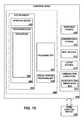
- FIG. 15is a block diagram illustrating physical components (i.e., hardware) of a computing device 1800 with which embodiments of the disclosure may be practiced.
- the computing device components described belowmay be suitable to act as the computing devices described above, such as wireless computing device and/or medical device of FIG. 1 .
- the computing device 1800may include at least one processing unit 1802 and a system memory 1804 .
- the system memory 1804may comprise, but is not limited to, volatile storage (e.g., random access memory), non-volatile storage (e.g., read-only memory), flash memory, or any combination of such memories.
- the system memory 1804may include an operating system 1805 and one or more program modules 1806 suitable for running software applications 1820 .
- the operating system 1805may be suitable for controlling the operation of the computing device 1800 .
- embodiments of the disclosuremay be practiced in conjunction with a graphics library, other operating systems, or any other application program and is not limited to any particular application or system.
- This basic configurationis illustrated in FIG. 15 by those components within a dashed line 1808 .
- the computing device 1800may have additional features or functionality.
- the computing device 1800may also include additional data storage devices (removable and/or non-removable) such as, for example, magnetic disks, optical disks, or tape. Such additional storage is illustrated in FIG. 15 by a removable storage device 1809 and a non-removable storage device 1810 .
- program modulesthat may be used in accordance with embodiments of the present disclosure, and in particular to generate screen content, may include electronic mail and contacts applications, word processing applications, spreadsheet applications, database applications, slide presentation applications, drawing or computer-aided application programs, etc.
- embodiments of the disclosuremay be practiced in an electrical circuit comprising discrete electronic elements, packaged or integrated electronic chips containing logic gates, a circuit utilizing a microprocessor, or on a single chip containing electronic elements or microprocessors.
- embodiments of the disclosuremay be practiced via a system-on-a-chip (SOC) where each or many of the components illustrated in FIG. 15 may be integrated onto a single integrated circuit.
- SOCsystem-on-a-chip
- Such an SOC devicemay include one or more processing units, graphics units, communications units, system virtualization units and various application functionality all of which are integrated (or “burned”) onto the chip substrate as a single integrated circuit.
- Embodiments of the disclosuremay also be practiced using other technologies capable of performing logical operations such as, for example, AND, OR, and NOT, including but not limited to mechanical, optical, fluidic, and quantum technologies.
- embodiments of the disclosuremay be practiced within a general purpose computer or in any other circuits or systems.
- the computing device 1800may also have one or more input device(s) 1812 such as a keyboard, a mouse, a pen, a sound or voice input device, a touch or swipe input device, etc.
- the output device(s) 1814such as a display, speakers, a printer, etc. may also be included.
- the aforementioned devicesare examples and others may be used.
- the computing device 1800may include one or more communication connections 1816 allowing communications with other computing devices 1818 . Examples of suitable communication connections 1816 include, but are not limited to, RF transmitter, receiver, and/or transceiver circuitry; universal serial bus (USB), parallel, and/or serial ports. Additionally, the communication connections 1816 can include a Bluetooth Low Energy Radio.
- Computer readable mediamay include non-transitory computer storage media.
- Computer storage mediamay include volatile and nonvolatile, removable and non-removable media implemented in any method or technology for storage of information, such as computer readable instructions, data structures, or program modules.
- the system memory 1804 , the removable storage device 1809 , and the non-removable storage device 1810are all computer storage media examples (i.e., memory storage.)
- Computer storage mediamay include RAM, ROM, electrically erasable read-only memory (EEPROM), flash memory or other memory technology, CD-ROM, digital versatile disks (DVD) or other optical storage, magnetic cassettes, magnetic tape, magnetic disk storage or other magnetic storage devices, or any other article of manufacture which can be used to store information and which can be accessed by the computing device 1800 . Any such computer storage media may be part of the computing device 1800 .
- Computer storage mediadoes not include a carrier wave or other propagated or modulated data signal.
- Communication mediamay be embodied by computer readable instructions, data structures, program modules, or other data in a modulated data signal, such as a carrier wave or other transport mechanism, and includes any information delivery media.
- modulated data signalmay describe a signal that has one or more characteristics set or changed in such a manner as to encode information in the signal.
- communication mediamay include wired media such as a wired network or direct-wired connection, and wireless media such as acoustic, radio frequency (RF), infrared, and other wireless media.
- RFradio frequency
- Embodiments of the present disclosuremay be utilized in various distributed computing environments where tasks are performed by remote processing devices that are linked through a communications network in a distributed computing environment.
Landscapes
- Health & Medical Sciences (AREA)
- Engineering & Computer Science (AREA)
- Life Sciences & Earth Sciences (AREA)
- Medical Informatics (AREA)
- Public Health (AREA)
- General Health & Medical Sciences (AREA)
- Biomedical Technology (AREA)
- Epidemiology (AREA)
- Primary Health Care (AREA)
- Pathology (AREA)
- Physics & Mathematics (AREA)
- Biophysics (AREA)
- Heart & Thoracic Surgery (AREA)
- Molecular Biology (AREA)
- Surgery (AREA)
- Animal Behavior & Ethology (AREA)
- Veterinary Medicine (AREA)
- General Business, Economics & Management (AREA)
- Business, Economics & Management (AREA)
- Data Mining & Analysis (AREA)
- Databases & Information Systems (AREA)
- Measuring And Recording Apparatus For Diagnosis (AREA)
Abstract
Description
Claims (19)
Priority Applications (3)
| Application Number | Priority Date | Filing Date | Title |
|---|---|---|---|
| US14/535,534US9763629B2 (en) | 2014-11-07 | 2014-11-07 | Medical device with context-specific interfaces |
| PCT/US2015/059505WO2016073872A1 (en) | 2014-11-07 | 2015-11-06 | Medical device with context-specific interfaces |
| US15/669,568US11037678B2 (en) | 2014-11-07 | 2017-08-04 | Medical device with interfaces for capturing vital signs data and affirmatively skipping parameters associated with the vital signs data |
Applications Claiming Priority (1)
| Application Number | Priority Date | Filing Date | Title |
|---|---|---|---|
| US14/535,534US9763629B2 (en) | 2014-11-07 | 2014-11-07 | Medical device with context-specific interfaces |
Related Child Applications (1)
| Application Number | Title | Priority Date | Filing Date |
|---|---|---|---|
| US15/669,568ContinuationUS11037678B2 (en) | 2014-11-07 | 2017-08-04 | Medical device with interfaces for capturing vital signs data and affirmatively skipping parameters associated with the vital signs data |
Publications (2)
| Publication Number | Publication Date |
|---|---|
| US20160128646A1 US20160128646A1 (en) | 2016-05-12 |
| US9763629B2true US9763629B2 (en) | 2017-09-19 |
Family
ID=55909870
Family Applications (2)
| Application Number | Title | Priority Date | Filing Date |
|---|---|---|---|
| US14/535,534Active2035-06-20US9763629B2 (en) | 2014-11-07 | 2014-11-07 | Medical device with context-specific interfaces |
| US15/669,568Active2035-07-14US11037678B2 (en) | 2014-11-07 | 2017-08-04 | Medical device with interfaces for capturing vital signs data and affirmatively skipping parameters associated with the vital signs data |
Family Applications After (1)
| Application Number | Title | Priority Date | Filing Date |
|---|---|---|---|
| US15/669,568Active2035-07-14US11037678B2 (en) | 2014-11-07 | 2017-08-04 | Medical device with interfaces for capturing vital signs data and affirmatively skipping parameters associated with the vital signs data |
Country Status (2)
| Country | Link |
|---|---|
| US (2) | US9763629B2 (en) |
| WO (1) | WO2016073872A1 (en) |
Cited By (2)
| Publication number | Priority date | Publication date | Assignee | Title |
|---|---|---|---|---|
| US11504071B2 (en) | 2018-04-10 | 2022-11-22 | Hill-Rom Services, Inc. | Patient risk assessment based on data from multiple sources in a healthcare facility |
| US11908581B2 (en) | 2018-04-10 | 2024-02-20 | Hill-Rom Services, Inc. | Patient risk assessment based on data from multiple sources in a healthcare facility |
Families Citing this family (5)
| Publication number | Priority date | Publication date | Assignee | Title |
|---|---|---|---|---|
| US9763629B2 (en) | 2014-11-07 | 2017-09-19 | Welch Allyn, Inc. | Medical device with context-specific interfaces |
| TW201618720A (en)* | 2014-11-20 | 2016-06-01 | 創心醫電股份有限公司 | Method, organ sound recorder, and system for organ sound acquisution |
| US10416865B2 (en)* | 2016-05-19 | 2019-09-17 | Welch Allyn, Inc. | Medical device with enhanced user interface controls |
| US10706602B2 (en)* | 2018-11-21 | 2020-07-07 | General Electric Company | Methods and apparatus to capture patient vitals in real time during an imaging procedure |
| US20200335190A1 (en)* | 2019-04-19 | 2020-10-22 | Hill-Rom Services, Inc. | Sepsis automated reporting system |
Citations (20)
| Publication number | Priority date | Publication date | Assignee | Title |
|---|---|---|---|---|
| US6188407B1 (en)* | 1998-03-04 | 2001-02-13 | Critikon Company, Llc | Reconfigurable user interface for modular patient monitor |
| US6458081B1 (en)* | 1999-04-23 | 2002-10-01 | Kabushiki Kaisha Toshiba | Ultrasonic diagnostic apparatus |
| US20070135730A1 (en)* | 2005-08-31 | 2007-06-14 | Tympany, Inc. | Interpretive Report in Automated Diagnostic Hearing Test |
| US20070138069A1 (en)* | 2005-12-19 | 2007-06-21 | Gambro Dasco S.P.A. To Gambro Lundia Ab. | Medical apparatus with improved user interface |
| US20070185390A1 (en) | 2003-08-19 | 2007-08-09 | Welch Allyn, Inc. | Information workflow for a medical diagnostic workstation |
| US20070260995A1 (en)* | 2006-05-08 | 2007-11-08 | Sap Ag. | Systems and methods for relating data to a task |
| US20080071251A1 (en)* | 2006-09-18 | 2008-03-20 | Maas Medical, Llc | Method and system for controlled infusion of therapeutic substances |
| US20090300620A1 (en)* | 2008-05-27 | 2009-12-03 | Samsung Electronics Co., Ltd. | Control device and method for providing user interface (ui) thereof |
| US20090313549A1 (en)* | 2008-06-16 | 2009-12-17 | Bruce Alan Casner | Configurable welding interface for automated welding applications |
| US20100131293A1 (en)* | 2008-11-26 | 2010-05-27 | General Electric Company | Interactive multi-axis longitudinal health record systems and methods of use |
| US7778851B2 (en) | 1996-12-30 | 2010-08-17 | I.M.D. Soft Ltd. | Medical information system |
| US20100235782A1 (en)* | 2009-03-11 | 2010-09-16 | Airstrip Development, L.P. | Systems and Methods For Viewing Patient Data |
| US20110029865A1 (en)* | 2009-07-31 | 2011-02-03 | Nellcor Puritan Bennett Llc | Control Interface For A Medical Monitor |
| US20110179361A1 (en)* | 2008-10-12 | 2011-07-21 | University Of Maryland, Baltimore | Predetermined presentation of patient data at bedsid |
| US20130044111A1 (en) | 2011-05-15 | 2013-02-21 | James VanGilder | User Configurable Central Monitoring Station |
| US20130267861A1 (en) | 2012-04-05 | 2013-10-10 | Welch Allyn, Inc. | User Interface Enhancements for Physiological Parameter Monitoring Platform Devices |
| US20130267793A1 (en) | 2012-04-05 | 2013-10-10 | Welch Allyn, Inc. | Physiological Parameter Measuring Platform Device Supporting Multiple Workflows |
| US20130283197A1 (en)* | 2009-12-18 | 2013-10-24 | Covidien Lp | Display of respiratory data graphs on a ventilator graphical user interface |
| US8843647B1 (en)* | 2008-06-05 | 2014-09-23 | United Services Automobile Association (Usaa) | Systems and methods for application server self-service console |
| US20160128646A1 (en)* | 2014-11-07 | 2016-05-12 | Welch Allyn, Inc. | Medical device with context-specific interfaces |
Family Cites Families (12)
| Publication number | Priority date | Publication date | Assignee | Title |
|---|---|---|---|---|
| US7606734B2 (en)* | 2000-07-11 | 2009-10-20 | The Western Union Company | Wide area network person-to-person payment |
| EP1711909A2 (en)* | 2004-02-06 | 2006-10-18 | Serge Clement Damiën Willems | Device, system and method for storing and exchanging medical data |
| US7945452B2 (en)* | 2005-04-11 | 2011-05-17 | Hospira, Inc. | User interface improvements for medical devices |
| US20080262870A1 (en)* | 2007-04-18 | 2008-10-23 | Siemens Medical Solutions Usa, Inc. | Computerized Treatment Order and Associated Alert Processing System |
| US8904349B2 (en)* | 2009-09-20 | 2014-12-02 | International Business Machines Corporation | Selectively applying changes to a version of a component |
| US8788502B1 (en)* | 2011-07-26 | 2014-07-22 | Google Inc. | Annotating articles |
| US20150012301A1 (en)* | 2012-02-01 | 2015-01-08 | Healarium Inc | Configurable platform for patient-centric actionable health data |
| US9996209B2 (en)* | 2012-05-02 | 2018-06-12 | Autodesk, Inc. | Techniques for representing and comparing workflows |
| US20150100877A1 (en)* | 2012-06-29 | 2015-04-09 | Yahoo! Inc. | Method or system for automated extraction of hyper-local events from one or more web pages |
| US8914308B2 (en)* | 2013-01-24 | 2014-12-16 | Bank Of America Corporation | Method and apparatus for initiating a transaction on a mobile device |
| CN104283843B (en)* | 2013-07-02 | 2018-12-07 | 腾讯科技(深圳)有限公司 | A kind of method, apparatus and system that user logs in |
| KR20150071166A (en)* | 2013-12-18 | 2015-06-26 | 삼성전자주식회사 | Server, User Terminal, Task management system, Method for managing task thereof |
- 2014
- 2014-11-07USUS14/535,534patent/US9763629B2/enactiveActive
- 2015
- 2015-11-06WOPCT/US2015/059505patent/WO2016073872A1/enactiveApplication Filing
- 2017
- 2017-08-04USUS15/669,568patent/US11037678B2/enactiveActive
Patent Citations (21)
| Publication number | Priority date | Publication date | Assignee | Title |
|---|---|---|---|---|
| US7778851B2 (en) | 1996-12-30 | 2010-08-17 | I.M.D. Soft Ltd. | Medical information system |
| US6188407B1 (en)* | 1998-03-04 | 2001-02-13 | Critikon Company, Llc | Reconfigurable user interface for modular patient monitor |
| US6458081B1 (en)* | 1999-04-23 | 2002-10-01 | Kabushiki Kaisha Toshiba | Ultrasonic diagnostic apparatus |
| US20070185390A1 (en) | 2003-08-19 | 2007-08-09 | Welch Allyn, Inc. | Information workflow for a medical diagnostic workstation |
| US20070135730A1 (en)* | 2005-08-31 | 2007-06-14 | Tympany, Inc. | Interpretive Report in Automated Diagnostic Hearing Test |
| US20070138069A1 (en)* | 2005-12-19 | 2007-06-21 | Gambro Dasco S.P.A. To Gambro Lundia Ab. | Medical apparatus with improved user interface |
| US20070260995A1 (en)* | 2006-05-08 | 2007-11-08 | Sap Ag. | Systems and methods for relating data to a task |
| US20080071251A1 (en)* | 2006-09-18 | 2008-03-20 | Maas Medical, Llc | Method and system for controlled infusion of therapeutic substances |
| US20090300620A1 (en)* | 2008-05-27 | 2009-12-03 | Samsung Electronics Co., Ltd. | Control device and method for providing user interface (ui) thereof |
| US8843647B1 (en)* | 2008-06-05 | 2014-09-23 | United Services Automobile Association (Usaa) | Systems and methods for application server self-service console |
| US20090313549A1 (en)* | 2008-06-16 | 2009-12-17 | Bruce Alan Casner | Configurable welding interface for automated welding applications |
| US20110179361A1 (en)* | 2008-10-12 | 2011-07-21 | University Of Maryland, Baltimore | Predetermined presentation of patient data at bedsid |
| US8832558B2 (en)* | 2008-10-12 | 2014-09-09 | University Of Maryland, Baltimore | Predetermined presentation of patient data at bedside |
| US20100131293A1 (en)* | 2008-11-26 | 2010-05-27 | General Electric Company | Interactive multi-axis longitudinal health record systems and methods of use |
| US20100235782A1 (en)* | 2009-03-11 | 2010-09-16 | Airstrip Development, L.P. | Systems and Methods For Viewing Patient Data |
| US20110029865A1 (en)* | 2009-07-31 | 2011-02-03 | Nellcor Puritan Bennett Llc | Control Interface For A Medical Monitor |
| US20130283197A1 (en)* | 2009-12-18 | 2013-10-24 | Covidien Lp | Display of respiratory data graphs on a ventilator graphical user interface |
| US20130044111A1 (en) | 2011-05-15 | 2013-02-21 | James VanGilder | User Configurable Central Monitoring Station |
| US20130267861A1 (en) | 2012-04-05 | 2013-10-10 | Welch Allyn, Inc. | User Interface Enhancements for Physiological Parameter Monitoring Platform Devices |
| US20130267793A1 (en) | 2012-04-05 | 2013-10-10 | Welch Allyn, Inc. | Physiological Parameter Measuring Platform Device Supporting Multiple Workflows |
| US20160128646A1 (en)* | 2014-11-07 | 2016-05-12 | Welch Allyn, Inc. | Medical device with context-specific interfaces |
Non-Patent Citations (1)
| Title |
|---|
| International Search Report and Written Opinion in PCT/US2015/059505, mailed Feb. 29, 2016, 15 pages. |
Cited By (2)
| Publication number | Priority date | Publication date | Assignee | Title |
|---|---|---|---|---|
| US11504071B2 (en) | 2018-04-10 | 2022-11-22 | Hill-Rom Services, Inc. | Patient risk assessment based on data from multiple sources in a healthcare facility |
| US11908581B2 (en) | 2018-04-10 | 2024-02-20 | Hill-Rom Services, Inc. | Patient risk assessment based on data from multiple sources in a healthcare facility |
Also Published As
| Publication number | Publication date |
|---|---|
| US11037678B2 (en) | 2021-06-15 |
| US20170329920A1 (en) | 2017-11-16 |
| US20160128646A1 (en) | 2016-05-12 |
| WO2016073872A1 (en) | 2016-05-12 |
Similar Documents
| Publication | Publication Date | Title |
|---|---|---|
| US11037678B2 (en) | Medical device with interfaces for capturing vital signs data and affirmatively skipping parameters associated with the vital signs data | |
| US12033754B2 (en) | Systems and methods for and displaying patient data | |
| CN105190681B (en) | System and method for integrating, unifying and presenting patient data across the healthcare continuum | |
| US9626479B2 (en) | Systems, methods, user interfaces and analysis tools for supporting user-definable rules and smart rules and smart alerts notification engine | |
| US10042979B2 (en) | Systems and methods for integrating, unifying and displaying patient data across healthcare continua | |
| US20230329650A1 (en) | Medical monitoring systems and methods | |
| US20180286500A1 (en) | System for acquisition, processing and visualization of clinical data of patients | |
| US20140249855A1 (en) | Systems And Methods For Integrating, Unifying And Displaying Patient Data Across Healthcare Continua | |
| US10217527B2 (en) | Systems and methods for integrating, unifying and displaying patient data across healthcare continua | |
| US10068057B2 (en) | Systems and methods for integrating, unifying and displaying patient data across healthcare continua | |
| US20230116079A1 (en) | Population health platform | |
| US20140278488A1 (en) | Systems and methods for and displaying patient data | |
| KR20180007232A (en) | Method and apparatus for providing service associated with health care | |
| US20220139550A1 (en) | Population health platform | |
| US20160128647A1 (en) | Medical Device With Enhanced Viewing Mode | |
| US10416865B2 (en) | Medical device with enhanced user interface controls | |
| Marx | Looking Towards the Future-Imagine the Possibilities |
Legal Events
| Date | Code | Title | Description |
|---|---|---|---|
| AS | Assignment | Owner name:WELCH ALLYN, INC., NEW YORK Free format text:ASSIGNMENT OF ASSIGNORS INTEREST;ASSIGNORS:KING, CATHERINE M.;MYERS, THOMAS A.;ST. PIERRE, SHAWN C.;AND OTHERS;SIGNING DATES FROM 20141110 TO 20141118;REEL/FRAME:034206/0295 | |
| AS | Assignment | Owner name:JPMORGAN CHASE BANK, N.A., AS COLLATERAL AGENT, ILLINOIS Free format text:SECURITY INTEREST;ASSIGNORS:ALLEN MEDICAL SYSTEMS, INC.;HILL-ROM SERVICES, INC.;ASPEN SURGICAL PRODUCTS, INC.;AND OTHERS;REEL/FRAME:036582/0123 Effective date:20150908 Owner name:JPMORGAN CHASE BANK, N.A., AS COLLATERAL AGENT, IL Free format text:SECURITY INTEREST;ASSIGNORS:ALLEN MEDICAL SYSTEMS, INC.;HILL-ROM SERVICES, INC.;ASPEN SURGICAL PRODUCTS, INC.;AND OTHERS;REEL/FRAME:036582/0123 Effective date:20150908 | |
| AS | Assignment | Owner name:JPMORGAN CHASE BANK, N.A., AS COLLATERAL AGENT, ILLINOIS Free format text:SECURITY AGREEMENT;ASSIGNORS:HILL-ROM SERVICES, INC.;ASPEN SURGICAL PRODUCTS, INC.;ALLEN MEDICAL SYSTEMS, INC.;AND OTHERS;REEL/FRAME:040145/0445 Effective date:20160921 Owner name:JPMORGAN CHASE BANK, N.A., AS COLLATERAL AGENT, IL Free format text:SECURITY AGREEMENT;ASSIGNORS:HILL-ROM SERVICES, INC.;ASPEN SURGICAL PRODUCTS, INC.;ALLEN MEDICAL SYSTEMS, INC.;AND OTHERS;REEL/FRAME:040145/0445 Effective date:20160921 | |
| STCF | Information on status: patent grant | Free format text:PATENTED CASE | |
| AS | Assignment | Owner name:HILL-ROM SERVICES, INC., ILLINOIS Free format text:RELEASE BY SECURED PARTY;ASSIGNOR:JPMORGAN CHASE BANK, N.A.;REEL/FRAME:050254/0513 Effective date:20190830 Owner name:ALLEN MEDICAL SYSTEMS, INC., ILLINOIS Free format text:RELEASE BY SECURED PARTY;ASSIGNOR:JPMORGAN CHASE BANK, N.A.;REEL/FRAME:050254/0513 Effective date:20190830 Owner name:MORTARA INSTRUMENT, INC., WISCONSIN Free format text:RELEASE BY SECURED PARTY;ASSIGNOR:JPMORGAN CHASE BANK, N.A.;REEL/FRAME:050254/0513 Effective date:20190830 Owner name:VOALTE, INC., FLORIDA Free format text:RELEASE BY SECURED PARTY;ASSIGNOR:JPMORGAN CHASE BANK, N.A.;REEL/FRAME:050254/0513 Effective date:20190830 Owner name:MORTARA INSTRUMENT SERVICES, INC., WISCONSIN Free format text:RELEASE BY SECURED PARTY;ASSIGNOR:JPMORGAN CHASE BANK, N.A.;REEL/FRAME:050254/0513 Effective date:20190830 Owner name:ANODYNE MEDICAL DEVICE, INC., FLORIDA Free format text:RELEASE BY SECURED PARTY;ASSIGNOR:JPMORGAN CHASE BANK, N.A.;REEL/FRAME:050254/0513 Effective date:20190830 Owner name:HILL-ROM COMPANY, INC., ILLINOIS Free format text:RELEASE BY SECURED PARTY;ASSIGNOR:JPMORGAN CHASE BANK, N.A.;REEL/FRAME:050254/0513 Effective date:20190830 Owner name:HILL-ROM, INC., ILLINOIS Free format text:RELEASE BY SECURED PARTY;ASSIGNOR:JPMORGAN CHASE BANK, N.A.;REEL/FRAME:050254/0513 Effective date:20190830 Owner name:WELCH ALLYN, INC., NEW YORK Free format text:RELEASE BY SECURED PARTY;ASSIGNOR:JPMORGAN CHASE BANK, N.A.;REEL/FRAME:050254/0513 Effective date:20190830 | |
| AS | Assignment | Owner name:JPMORGAN CHASE BANK, N.A., ILLINOIS Free format text:SECURITY AGREEMENT;ASSIGNORS:HILL-ROM HOLDINGS, INC.;HILL-ROM, INC.;HILL-ROM SERVICES, INC.;AND OTHERS;REEL/FRAME:050260/0644 Effective date:20190830 | |
| MAFP | Maintenance fee payment | Free format text:PAYMENT OF MAINTENANCE FEE, 4TH YEAR, LARGE ENTITY (ORIGINAL EVENT CODE: M1551); ENTITY STATUS OF PATENT OWNER: LARGE ENTITY Year of fee payment:4 | |
| AS | Assignment | Owner name:HILL-ROM HOLDINGS, INC., ILLINOIS Free format text:RELEASE OF SECURITY INTEREST AT REEL/FRAME 050260/0644;ASSIGNOR:JPMORGAN CHASE BANK, N.A.;REEL/FRAME:058517/0001 Effective date:20211213 Owner name:BARDY DIAGNOSTICS, INC., ILLINOIS Free format text:RELEASE OF SECURITY INTEREST AT REEL/FRAME 050260/0644;ASSIGNOR:JPMORGAN CHASE BANK, N.A.;REEL/FRAME:058517/0001 Effective date:20211213 Owner name:VOALTE, INC., FLORIDA Free format text:RELEASE OF SECURITY INTEREST AT REEL/FRAME 050260/0644;ASSIGNOR:JPMORGAN CHASE BANK, N.A.;REEL/FRAME:058517/0001 Effective date:20211213 Owner name:HILL-ROM, INC., ILLINOIS Free format text:RELEASE OF SECURITY INTEREST AT REEL/FRAME 050260/0644;ASSIGNOR:JPMORGAN CHASE BANK, N.A.;REEL/FRAME:058517/0001 Effective date:20211213 Owner name:WELCH ALLYN, INC., NEW YORK Free format text:RELEASE OF SECURITY INTEREST AT REEL/FRAME 050260/0644;ASSIGNOR:JPMORGAN CHASE BANK, N.A.;REEL/FRAME:058517/0001 Effective date:20211213 Owner name:ALLEN MEDICAL SYSTEMS, INC., ILLINOIS Free format text:RELEASE OF SECURITY INTEREST AT REEL/FRAME 050260/0644;ASSIGNOR:JPMORGAN CHASE BANK, N.A.;REEL/FRAME:058517/0001 Effective date:20211213 Owner name:HILL-ROM SERVICES, INC., ILLINOIS Free format text:RELEASE OF SECURITY INTEREST AT REEL/FRAME 050260/0644;ASSIGNOR:JPMORGAN CHASE BANK, N.A.;REEL/FRAME:058517/0001 Effective date:20211213 Owner name:BREATHE TECHNOLOGIES, INC., CALIFORNIA Free format text:RELEASE OF SECURITY INTEREST AT REEL/FRAME 050260/0644;ASSIGNOR:JPMORGAN CHASE BANK, N.A.;REEL/FRAME:058517/0001 Effective date:20211213 | |
| MAFP | Maintenance fee payment | Free format text:PAYMENT OF MAINTENANCE FEE, 8TH YEAR, LARGE ENTITY (ORIGINAL EVENT CODE: M1552); ENTITY STATUS OF PATENT OWNER: LARGE ENTITY Year of fee payment:8 |