US9763602B2 - Intra-operative heart size measuring tool - Google Patents
Intra-operative heart size measuring toolDownload PDFInfo
- Publication number
- US9763602B2 US9763602B2US15/223,973US201615223973AUS9763602B2US 9763602 B2US9763602 B2US 9763602B2US 201615223973 AUS201615223973 AUS 201615223973AUS 9763602 B2US9763602 B2US 9763602B2
- Authority
- US
- United States
- Prior art keywords
- support members
- heart
- cord
- measurement tool
- measuring
- Prior art date
- Legal status (The legal status is an assumption and is not a legal conclusion. Google has not performed a legal analysis and makes no representation as to the accuracy of the status listed.)
- Active
Links
Images


Classifications
- A—HUMAN NECESSITIES
- A61—MEDICAL OR VETERINARY SCIENCE; HYGIENE
- A61B—DIAGNOSIS; SURGERY; IDENTIFICATION
- A61B5/00—Measuring for diagnostic purposes; Identification of persons
- A61B5/103—Measuring devices for testing the shape, pattern, colour, size or movement of the body or parts thereof, for diagnostic purposes
- A61B5/107—Measuring physical dimensions, e.g. size of the entire body or parts thereof
- A61B5/1076—Measuring physical dimensions, e.g. size of the entire body or parts thereof for measuring dimensions inside body cavities, e.g. using catheters
- A—HUMAN NECESSITIES
- A61—MEDICAL OR VETERINARY SCIENCE; HYGIENE
- A61B—DIAGNOSIS; SURGERY; IDENTIFICATION
- A61B17/00—Surgical instruments, devices or methods
- A61B17/00234—Surgical instruments, devices or methods for minimally invasive surgery
- A—HUMAN NECESSITIES
- A61—MEDICAL OR VETERINARY SCIENCE; HYGIENE
- A61B—DIAGNOSIS; SURGERY; IDENTIFICATION
- A61B5/00—Measuring for diagnostic purposes; Identification of persons
- A61B5/0033—Features or image-related aspects of imaging apparatus, e.g. for MRI, optical tomography or impedance tomography apparatus; Arrangements of imaging apparatus in a room
- A61B5/004—Features or image-related aspects of imaging apparatus, e.g. for MRI, optical tomography or impedance tomography apparatus; Arrangements of imaging apparatus in a room adapted for image acquisition of a particular organ or body part
- A61B5/0044—Features or image-related aspects of imaging apparatus, e.g. for MRI, optical tomography or impedance tomography apparatus; Arrangements of imaging apparatus in a room adapted for image acquisition of a particular organ or body part for the heart
- A—HUMAN NECESSITIES
- A61—MEDICAL OR VETERINARY SCIENCE; HYGIENE
- A61B—DIAGNOSIS; SURGERY; IDENTIFICATION
- A61B5/00—Measuring for diagnostic purposes; Identification of persons
- A61B5/103—Measuring devices for testing the shape, pattern, colour, size or movement of the body or parts thereof, for diagnostic purposes
- A61B5/107—Measuring physical dimensions, e.g. size of the entire body or parts thereof
- A—HUMAN NECESSITIES
- A61—MEDICAL OR VETERINARY SCIENCE; HYGIENE
- A61B—DIAGNOSIS; SURGERY; IDENTIFICATION
- A61B5/00—Measuring for diagnostic purposes; Identification of persons
- A61B5/68—Arrangements of detecting, measuring or recording means, e.g. sensors, in relation to patient
- A61B5/6846—Arrangements of detecting, measuring or recording means, e.g. sensors, in relation to patient specially adapted to be brought in contact with an internal body part, i.e. invasive
- A61B5/6867—Arrangements of detecting, measuring or recording means, e.g. sensors, in relation to patient specially adapted to be brought in contact with an internal body part, i.e. invasive specially adapted to be attached or implanted in a specific body part
- A61B5/6869—Heart
- A—HUMAN NECESSITIES
- A61—MEDICAL OR VETERINARY SCIENCE; HYGIENE
- A61F—FILTERS IMPLANTABLE INTO BLOOD VESSELS; PROSTHESES; DEVICES PROVIDING PATENCY TO, OR PREVENTING COLLAPSING OF, TUBULAR STRUCTURES OF THE BODY, e.g. STENTS; ORTHOPAEDIC, NURSING OR CONTRACEPTIVE DEVICES; FOMENTATION; TREATMENT OR PROTECTION OF EYES OR EARS; BANDAGES, DRESSINGS OR ABSORBENT PADS; FIRST-AID KITS
- A61F2/00—Filters implantable into blood vessels; Prostheses, i.e. artificial substitutes or replacements for parts of the body; Appliances for connecting them with the body; Devices providing patency to, or preventing collapsing of, tubular structures of the body, e.g. stents
- A61F2/02—Prostheses implantable into the body
- A61F2/24—Heart valves ; Vascular valves, e.g. venous valves; Heart implants, e.g. passive devices for improving the function of the native valve or the heart muscle; Transmyocardial revascularisation [TMR] devices; Valves implantable in the body
- A61F2/2478—Passive devices for improving the function of the heart muscle, i.e. devices for reshaping the external surface of the heart, e.g. bags, strips or bands
- A61F2/2481—Devices outside the heart wall, e.g. bags, strips or bands
- A—HUMAN NECESSITIES
- A61—MEDICAL OR VETERINARY SCIENCE; HYGIENE
- A61F—FILTERS IMPLANTABLE INTO BLOOD VESSELS; PROSTHESES; DEVICES PROVIDING PATENCY TO, OR PREVENTING COLLAPSING OF, TUBULAR STRUCTURES OF THE BODY, e.g. STENTS; ORTHOPAEDIC, NURSING OR CONTRACEPTIVE DEVICES; FOMENTATION; TREATMENT OR PROTECTION OF EYES OR EARS; BANDAGES, DRESSINGS OR ABSORBENT PADS; FIRST-AID KITS
- A61F2/00—Filters implantable into blood vessels; Prostheses, i.e. artificial substitutes or replacements for parts of the body; Appliances for connecting them with the body; Devices providing patency to, or preventing collapsing of, tubular structures of the body, e.g. stents
- A61F2/02—Prostheses implantable into the body
- A61F2/24—Heart valves ; Vascular valves, e.g. venous valves; Heart implants, e.g. passive devices for improving the function of the native valve or the heart muscle; Transmyocardial revascularisation [TMR] devices; Valves implantable in the body
- A61F2/2496—Devices for determining the dimensions of the prosthetic valve to be implanted, e.g. templates, sizers
- A—HUMAN NECESSITIES
- A61—MEDICAL OR VETERINARY SCIENCE; HYGIENE
- A61B—DIAGNOSIS; SURGERY; IDENTIFICATION
- A61B17/00—Surgical instruments, devices or methods
- A61B17/00234—Surgical instruments, devices or methods for minimally invasive surgery
- A61B2017/00238—Type of minimally invasive operation
- A61B2017/00243—Type of minimally invasive operation cardiac
- A—HUMAN NECESSITIES
- A61—MEDICAL OR VETERINARY SCIENCE; HYGIENE
- A61B—DIAGNOSIS; SURGERY; IDENTIFICATION
- A61B90/00—Instruments, implements or accessories specially adapted for surgery or diagnosis and not covered by any of the groups A61B1/00 - A61B50/00, e.g. for luxation treatment or for protecting wound edges
- A61B90/06—Measuring instruments not otherwise provided for
- A61B2090/061—Measuring instruments not otherwise provided for for measuring dimensions, e.g. length
- A—HUMAN NECESSITIES
- A61—MEDICAL OR VETERINARY SCIENCE; HYGIENE
- A61B—DIAGNOSIS; SURGERY; IDENTIFICATION
- A61B90/00—Instruments, implements or accessories specially adapted for surgery or diagnosis and not covered by any of the groups A61B1/00 - A61B50/00, e.g. for luxation treatment or for protecting wound edges
- A61B90/06—Measuring instruments not otherwise provided for
Definitions
- the inventionis a tool for measuring the size of a heart in situ.
- Cardiac support devicesused to treat heart disease are generally known and disclosed, for example, in International Publication No. WO 2008/003034 which is incorporated herein by reference in its entirety.
- CSDs and tools and methods for surgically delivering or implanting the devicesare also generally known and disclosed, for example, in International Publication No. WO 2008/011411 which is incorporated herein by reference in its entirety.
- Sizes of diseased heartscan vary. Accordingly, CSDs come in a range of sizes. Prior to the delivery procedure, a surgeon will typically measure the size of the patient's heart, and select an appropriately sized CSD. One known approach for measuring the patient's heart size is through CT imaging under fluoroscopy. Heart size measuring tools are also disclosed in the Vanden Hoek et al. U.S. Pat. No. 6,575,921 and the Krueger U.S. Pat. No. 6,179,791.
- the inventionis an improved intra-operative heart size measuring tool.
- the toolcan be efficiently used to provide accurate measurements of a heart size.
- One embodiment of the toolincludes a tubular body, a flexible measuring cord having length indicia, a measuring cord support mechanism and an actuating mechanism.
- the actuating mechanismmoves the measuring cord support mechanism between retracted and extended states with respect to the body to drive the measuring cord between a collapsed position and a measuring position. When the measuring cord is in the measuring position the measuring cord extends around a portion of the heart to be measured.
- Another embodiment of the inventionincludes a scale that can be used in connection with the indicia on the measuring cord to provide a reading of the heart size.
- FIG. 1is an isometric illustration of a heart size measuring tool in accordance with one embodiment of the invention, with the measuring cord support mechanism shown in the extended position.
- FIG. 2is an isometric illustration of the heart size measuring tool shown in FIG. 1 , with the measuring cord support mechanism shown in the retracted position.
- FIG. 3is an isometric illustration of the distal end of the measuring tool shown in FIG. 1 , with the measuring cord support mechanism in the extended state and the measuring cord in a measuring position around the atrioventricular groove of a heart.
- FIG. 4is an isometric illustration of a heart size measuring tool in accordance with another embodiment of the invention, having a suction cup and shown with the measuring cord support mechanism in the extended position.
- FIG. 5is an isometric illustration of the heart size measuring tool shown in FIG. 4 , with the measuring cord support mechanism shown in the retracted position.
- FIG. 6is an isometric illustration of a heart size measuring tool in accordance with another embodiment of the invention, having ties between the support members of the measuring cord support mechanism and shown with the support mechanism in the extended position.
- FIG. 7is a detailed illustration of a pair of support members and a tie of the measuring tool shown in FIG. 6 .
- FIG. 8is an isometric illustration of a heart size measuring tool in accordance with another embodiment of the invention, having radiopaque markers on the support members of the measuring cord support mechanism and shown with the support mechanism in the extended position.
- FIG. 9is an isometric illustration of a heart size measuring tool in accordance with another embodiment of the invention, having deflection sensors on the support members and shown with the support mechanism in the extended position.
- FIG. 10is an isometric illustration of a heart size measuring tool in accordance with another embodiment of the invention, having EEG or other sensor electrodes on the support members and shown with the support mechanism in the extended position.
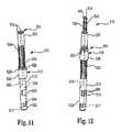
- FIG. 11is an is isometric illustration of a heart size measuring tool in accordance with another embodiment of the invention, shown with the support mechanism in the retracted position.
- FIG. 12is an isometric illustration of the heart size measurement tool shown in FIG. 11 , with the support mechanism in the extended and unactuated position.
- FIG. 13is an isometric illustration of the heart size measurement tool shown in FIG. 11 , with the support mechanism in the extended and partially actuated position.
- FIG. 14is an isometric illustration of the distal end of the measuring tool shown in FIGS. 11-13 , with the measuring cord support mechanism in the extended state and partially actuated to extend the measuring cord around a portion of the atrioventricular groove of a heart.
- FIG. 15is an isometric illustration of the distal end of the measuring tool shown in FIGS. 11-13 , with the measuring cord support mechanism in the extended state and fully actuated to extend the measuring cord around the atrioventricular groove of a heart.
- Measuring tool 10includes body 12 , measuring cord 14 , measuring cord support mechanism 16 , actuating mechanism 18 , measuring cord retraction mechanism 17 and scale 19 .
- Body 12is a generally tubular member having a distal end 20 , proximal end 22 and a plurality of elongated slots 24 (six are shown in the illustrated embodiment) extending through the body at a location adjacent to the actuating mechanism 18 .
- Actuating mechanism 18includes a handle 26 that is slidably mounted to the body 12 . Engagement structures such as pins 28 on the handle 26 extend into the slots 24 .
- Measuring cord support mechanism 16includes a plurality (six are shown) of support members 30 within the body 12 . Proximal ends (not visible) of each of the support members 30 are connected to the pins 28 within the body 12 . Other embodiments (not shown) include other structures operatively coupling the handle 26 to the support members 30 .
- Support members 30are elongated and resilient members. Each of the support members 30 includes one or more guides 40 , shown as loops in the illustrated embodiment, for supporting the measuring cord 14 .
- each of the support members 30has a guide 40 located near the distal end of the support member.
- One of the support members 30also has a number of guides 40 at spaced locations along its length.
- measuring cord 14extends through the guides 40 at the ends of the support members 30 , and into the body 12 through the guides 40 along the length of the one support member.
- One end 42 of the measuring cord 14is fixedly mounted to the body 12 .
- the other end 44 of the measuring cord 14is mounted to the retraction mechanism 17 .
- Cord retraction mechanism 17can be a spring-loaded spool that is biased to wind up slack portions of the measuring cord 14 .
- Measuring cord 14has indicia such as graduated length markings 46 in the embodiment shown in FIG. 1 .
- Handle 26is actuated to drive the measuring cord support mechanism 16 between a first or retracted state shown in FIG. 2 and a second or extended state shown in FIGS. 1 and 3 .
- the support members 30are in a reduced-diameter configuration. In the illustrated embodiment this configuration is achieved by the actuating mechanism 18 withdrawing the support members 30 completely into the distal end 20 of the body 12 .
- the support members 30extend partially out of the body 12 when the support mechanism 16 is in its retracted state.
- the support members 30pull the measuring cord 14 into a collapsed position.
- Retraction mechanism 17can retract and retain portions of the measuring cord when the support mechanism 16 is in the retracted state.
- the support members 30extend from the distal end 20 of the body 12 .
- the measuring cord 14is thereby forced out of the body 12 , with portions of the measuring cord being withdrawn from retraction mechanism 17 and sliding through the guides 40 .
- Tool 10is used to measure the size of a patient's heart.
- the measurements taken by the tool 10can be used to select the size of a cardiac support device (CSD) being applied to the patient's heart.
- CSDcardiac support device
- Use of the tool 10will typically begin with the measuring cord support mechanism 16 in the retracted state.
- the distal end 20 of the tool 10can then be inserted through an opening in the patient's chest and pericardium (not shown) and positioned at a measurement position at the apex of the patient's heart.
- the tool 10can be inserted through a minimal access site such as a thoracotomy. Fluoroscopic guidance can be used to position the tool 10 .
- the tool 10can be sized or otherwise configured so that the handle 26 and scale 19 are located outside of the patient's body when the distal end 20 of the tool is located at the measurement position.
- the handle 26is then actuated to drive the measuring cord support mechanism 16 to the extended state with the support members 30 extending around the heart and positioning the measurement cord 14 in the measurement position around the heart at the target location to be measured.
- the support members 30can be telescoping.
- the circumference of the heartcan be read from scale 19 based on the indicia 46 on the measuring cord.
- the indicia 46can be calibrated in such a manner that the indicia closest to a marker on scale 19 represents the circumference of the heart at the target location.
- the handle 26can be actuated to return the measuring cord support mechanism 16 to the retracted state, and the tool 10 withdrawn from the patient.
- the tool 10is described above as a dedicated measurement instrument.
- the measuring cordcan be incorporated onto other tools such as the CSD delivery tools described in the international applications referred to above in the background section.
- the measuring cordcan be incorporated onto the retractable/extendable CSD deployment mechanism shown in the international applications (i.e., the deployment mechanism would serve a dual function), or a separate measuring cord support mechanism in addition to the CSD deployment mechanism can be used.
- the measuring cord 14can be radiopaque to enhance its visibility under fluoroscopic or other imaging modalities during the use of tool 10 (e.g., as an aide to positioning the measuring cord).
- the measuring cord 14can have radiopaque or other markers at predetermined locations. These markers can be viewed under an imaging modality (e.g., during an echocardiogram (ECHO) or transesophageal echo (TEE)) to determine the size of the heart. The markers can be made distinguishable from one another to enhance the accuracy of the measurement reading.
- the measuring cordcan be color coded to facilitate measurement readings.
- Yet other embodiments of the inventionmake use of other structures or approaches for determining the size of the heart based on the length of the cord extended during the deployment of the measuring tool and for providing a visual display representative of the measured heart size.
- an instrument operatively coupled to the retraction mechanismcan measure and provide a visual indication of heart size based on the length of the measuring cord withdrawn from the retraction mechanism.
- Windows with indicia or other features enabling measurement readingscan also be located on the support members 30 .
- FIGS. 4 and 5illustrate a measuring tool 110 in accordance with another embodiment of the invention.
- a suction cup 121is located on the distal end 120 of measuring tool 110 .
- the suction cup 121is connected to a vacuum source through a tube (not shown) that extends through all or a portion of body 112 .
- a valve (not shown) on body 112 or elsewherecan be used to control the application of the vacuum to the suction cup 121 .
- the suction cup 121functions as a releasable suction device to hold the measuring tool 110 on the patient's heart and to stabilize the heart during the measurement procedure (including during the deployment and withdrawal of the measuring cord support mechanism 116 ). For example, when the measuring cord support mechanism 116 is in the retracted state shown in FIG.
- the suction cup 121can be positioned adjacent to the apex of the patient's heart and connected to the vacuum source to secure the body 112 to the heart. Support mechanism 116 can then be deployed to the extended state while the suction cup 121 provides traction holding the body 120 to the heart. The vacuum source can be disconnected from the suction cup 121 when the traction provided by the cup is no longer needed (e.g., after the support mechanism 116 is returned to its retracted state).
- tool 110can be substantially the same as or similar to tool 10 described above, and similar features are identified by similar reference numbers.
- FIG. 6is an illustration of a heart size measuring tool 110 ′ in accordance with another embodiment of the invention having ties 145 ′ connecting adjacent support members 130 ′.
- FIG. 7is a detailed illustration of one of the ties 145 ′.
- the ties 145 ′open and collapse with the support members 130 ′ when the support mechanism 116 ′ is moved between the extended and retracted states, and help keep the adjacent support members properly spaced (e.g., generally equidistant) from one another.
- the ties 145 ′provide this function by providing resistance to any forces that might tend to cause the support members 130 ′ to collapse toward one another.
- the ties 145 ′are folded elongated members such as malleable metal strips having their opposite ends attached to the support members 130 ′ (e.g., by welds or adhesive 143 ′).
- Other structures for maintaining the spacing between the support members 130 ′can be used in other embodiments (not shown).
- physical stops on the measurement cord that engage the guides on the support memberscan be located at predetermined spaced-apart locations on the measurement cord to provide or limit the maximum distance between the support members.
- tool 110 ′can be substantially the same as or similar to tool 110 described above, and similar features are identified by similar reference numbers.
- the support memberscan have stiffnesses that vary along the length of the members.
- the stiffness of the support memberscan be different in different directions.
- variable thicknesscan be provided by internal movable stylets, inflation, changing thicknesses and changing cross-sectional shapes along the length of the members.
- the dimension of the members in a radial direction with respect to a longitudinal axis through the tool 10can be smaller than the dimension in the circumferential direction, enabling the support members to be relatively rigid in connection with movement around the heart, yet relatively flexible when moved toward or away from the heart.
- the support memberscan also be malleable (e.g., metal or metal reinforced polymer) so they can be shaped by the physician or other person operating the tool.
- FIG. 8is an illustration of heart size measuring tool 210 in accordance with another embodiment of the invention.
- One or more radiopaque or other markers 251e.g., piezoelectric crystals
- a plurality of markers 251are shown in each support member 230 in the illustrated embodiment, including a marker on the distal end of the support members.
- the markers 251can be coded or otherwise made uniquely identifiable or distinguishable from one another. Fluoroscopic, ECHO, TEE or other appropriate imaging modalities can be used to image the measuring tool 210 when the support members 230 are positioned on the patient's heart, and the locations and spacing of the markers 251 can be used to determine the size of the heart.
- a fluoroscopic image taken generally parallel to the longitudinal axis of the tool 210will show the markers 251 in a generally circular pattern.
- the external diameter of the hemican be interpolated and estimated from this image.
- tool 210can be substantially the same as or similar to tool 10 described above, and similar features are identified by similar reference numbers.
- Still other embodiments of the invention(not shown) have a support mechanism with markers such as those of the embodiment shown in FIG. 8 , but do not include the measuring cord and associated components such as the retraction mechanism and scale.
- Markers 251can then enable fluoroscopic or other imaging-based estimates of the longitudinal length of the heart and/or CSD. Dimension information for both length and circumference are available, facilitating the selection of the most appropriately-sized CSD for implantation. Similarly, this feature will enable “mapping” of the heart. The circumference of the heart at planes parallel to the base at locations between the base and apex of the heart can be measured. This information can be used to estimate the surface area/shape of the heart. This additional information can further enhance correct CSD size selection.
- FIG. 9is an illustration of a heart size measuring tool 310 in accordance with another embodiment of the invention.
- the tool 310includes one or more deflection sensors 361 located on each support member 330 (a plurality of sensors 361 are shown on each support member in the illustrated embodiment).
- Sensors 361which can for example be strain gauge sensors, are operatively connected to an instrument unit 365 (e.g., by wires, not shown, through cable 363 ).
- the instrument unit 365provides any drive power or signals needed for operation of the sensors 361 .
- the support mechanism 316is positioned around the patient's heart, the support members 330 will be deflected by amounts representative of the size of the heart.
- measuring tool 310can be substantially the same as or similar to tool 110 described above, and similar features are identified by similar reference numbers.
- the sensors on the support membersinclude transmitting and receiving devices coupled to an instrument unit.
- the instrument unitcan use Doppler or other methodologies to detect the relative positioning of the sensors and produce a heart size measurement.
- FIG. 10is an illustration of a heart size measuring tool 410 in accordance with another embodiment of the invention.
- the tool 410includes a plurality of sensor electrodes 451 located on each support member 430 .
- Sensor electrodes 451are connected to an instrument unit 467 by wires (not shown) through cable 469 .
- Sensor electrodes 451 and instrument unit 467which can, for example, be electrocardiogram (ECG) electrodes and instrumentation, are used to map the electrical potentials across the surface of the heart while the tool 410 is also used to measure the heart size.
- ECGelectrocardiogram
- the measuring tool 410can be moved (e.g., rotated) to place the sensor electrodes 451 at different locations on the heart to enable electrical potential measurements across the surface of the heart.
- tool 410can be substantially the same as or similar to tool 10 described above, and similar features are identified by similar reference numbers.
- the sensor electrodes 451can also be used to locate the measuring tool 410 .
- the electrocardiogram signal produced by the hearthas different characteristics above and below the A-V groove. By monitoring these signals using the sensor electrodes 451 , and in particular using the signals from electrodes near the ends of the support members 430 , the location of the A-V groove can be identified.
- FIGS. 11-13are illustrations of a heart size measuring tool 510 in accordance with another embodiment of the invention.
- the tool 510includes a support mechanism 516 having two support members 530 .
- the measuring cord 514extends from the body 512 along each support member 530 through guides 540 , and between the guides 540 at the ends of the support members.
- Support members 530are connected to actuating mechanism 518 .
- Actuating mechanism 518can be actuated to move the support members 530 between a retracted position shown in FIG. 11 and an extended position shown in FIGS. 12 and 13 .
- Measuring tool 510also includes a measurement actuator 555 coupled to one or both of the support members 530 .
- the measurement actuator 555is operated to drive the support members 530 between the unactuated measurement position shown in FIG. 12 to an actuated measurement position.
- the support members 530can be positioned adjacent to one another in the unactuated measurement position.
- the support members 530are shown in a partially actuated position in FIG. 13 , with the support members spaced from one another to extend the measuring cord 514 .
- the support members 530can have features of any of the embodiments described above.
- measuring tool 510can be described with reference to FIGS. 11-15 .
- the actuating mechanism 518is operated to move the support mechanism 516 from the retracted position shown in FIG. 11 to the extended position shown in FIG. 12 .
- the tool 510is then manipulated to position the distal ends of the support members 530 at the target measurement location on the heart.
- the support mechanism 516is initially moved to the extended position the support members 530 can be in an unactuated position with respect to one another.
- the measurement actuator 555is then operated to move the support members 530 with respect to one another to extend the measuring cord 514 along the measurement target on the heart.
- one of the support members 530remains stationary, and the other support member is revolved around the heart.
- FIG. 14shows the support members 530 in a partially actuated position with the measuring cord 514 extended along a portion of the heart near the A-V groove.
- FIG. 15shows the support members 530 fully actuated, with the measuring cord 514 in the measurement position extended around the heart at the A-V groove.
- the measured dimension of the heartcan be read from scale 519 when the measuring cord 514 is in the measurement position.
- Magnets or other structures on the support members 530can releasably lock the support members together after one of the support members has fully moved around the heart with respect to the other support member and contacts the other support member, thereby aiding the measurement.
- the measurement actuator 555can be operated to return the support members 530 to the unactuated position.
- the actuating mechanism 518can then be operated to retract the support mechanism before removing the tool from the patient.
- tool 510can be substantially the same as or similar to tool 10 described above, and similar features are identified by similar reference numbers.
- Measuring tools in accordance with the inventionoffer a number of important advantages. They are relatively efficient to operate and make use of surgical access incisions that will be used for the delivery of the CSD.
- the toolsare capable of providing accurate measurements at any desired location on the heart.
- Enhanced CSD sizingis enabled since measurements of the heart size can be made relatively close in time to the delivery of the CSD.
- the need for other imaging modalities used for heart size measurementcan be eliminated.
- Other functionalitysuch as electrical mapping can be provided concurrently.
Landscapes
- Health & Medical Sciences (AREA)
- Life Sciences & Earth Sciences (AREA)
- Cardiology (AREA)
- Animal Behavior & Ethology (AREA)
- Veterinary Medicine (AREA)
- Engineering & Computer Science (AREA)
- Biomedical Technology (AREA)
- Heart & Thoracic Surgery (AREA)
- Public Health (AREA)
- General Health & Medical Sciences (AREA)
- Surgery (AREA)
- Medical Informatics (AREA)
- Molecular Biology (AREA)
- Biophysics (AREA)
- Pathology (AREA)
- Physics & Mathematics (AREA)
- Oral & Maxillofacial Surgery (AREA)
- Transplantation (AREA)
- Vascular Medicine (AREA)
- Nuclear Medicine, Radiotherapy & Molecular Imaging (AREA)
- Dentistry (AREA)
- Radiology & Medical Imaging (AREA)
- Ultra Sonic Daignosis Equipment (AREA)
- Apparatus For Radiation Diagnosis (AREA)
- Media Introduction/Drainage Providing Device (AREA)
- Measurement Of The Respiration, Hearing Ability, Form, And Blood Characteristics Of Living Organisms (AREA)
- Measuring Pulse, Heart Rate, Blood Pressure Or Blood Flow (AREA)
Abstract
Description
Claims (12)
Priority Applications (2)
| Application Number | Priority Date | Filing Date | Title |
|---|---|---|---|
| US15/223,973US9763602B2 (en) | 2009-03-27 | 2016-07-29 | Intra-operative heart size measuring tool |
| US15/707,560US20180000381A1 (en) | 2009-03-27 | 2017-09-18 | Intra-Operative Heart Size Measuring Tool |
Applications Claiming Priority (5)
| Application Number | Priority Date | Filing Date | Title |
|---|---|---|---|
| US16418309P | 2009-03-27 | 2009-03-27 | |
| PCT/US2010/028830WO2010111592A1 (en) | 2009-03-27 | 2010-03-26 | Intra-operative heart size measuring tool |
| US201213261173A | 2012-06-29 | 2012-06-29 | |
| US14/698,689US9427318B2 (en) | 2009-03-27 | 2015-04-28 | Intra-operative heart size measuring tool |
| US15/223,973US9763602B2 (en) | 2009-03-27 | 2016-07-29 | Intra-operative heart size measuring tool |
Related Parent Applications (1)
| Application Number | Title | Priority Date | Filing Date |
|---|---|---|---|
| US14/698,689ContinuationUS9427318B2 (en) | 2009-03-27 | 2015-04-28 | Intra-operative heart size measuring tool |
Related Child Applications (1)
| Application Number | Title | Priority Date | Filing Date |
|---|---|---|---|
| US15/707,560ContinuationUS20180000381A1 (en) | 2009-03-27 | 2017-09-18 | Intra-Operative Heart Size Measuring Tool |
Publications (2)
| Publication Number | Publication Date |
|---|---|
| US20160345866A1 US20160345866A1 (en) | 2016-12-01 |
| US9763602B2true US9763602B2 (en) | 2017-09-19 |
Family
ID=42781545
Family Applications (4)
| Application Number | Title | Priority Date | Filing Date |
|---|---|---|---|
| US13/261,173Active2032-05-29US9044169B2 (en) | 2009-03-27 | 2010-03-26 | Intra-operative heart size measuring tool |
| US14/698,689Expired - Fee RelatedUS9427318B2 (en) | 2009-03-27 | 2015-04-28 | Intra-operative heart size measuring tool |
| US15/223,973ActiveUS9763602B2 (en) | 2009-03-27 | 2016-07-29 | Intra-operative heart size measuring tool |
| US15/707,560AbandonedUS20180000381A1 (en) | 2009-03-27 | 2017-09-18 | Intra-Operative Heart Size Measuring Tool |
Family Applications Before (2)
| Application Number | Title | Priority Date | Filing Date |
|---|---|---|---|
| US13/261,173Active2032-05-29US9044169B2 (en) | 2009-03-27 | 2010-03-26 | Intra-operative heart size measuring tool |
| US14/698,689Expired - Fee RelatedUS9427318B2 (en) | 2009-03-27 | 2015-04-28 | Intra-operative heart size measuring tool |
Family Applications After (1)
| Application Number | Title | Priority Date | Filing Date |
|---|---|---|---|
| US15/707,560AbandonedUS20180000381A1 (en) | 2009-03-27 | 2017-09-18 | Intra-Operative Heart Size Measuring Tool |
Country Status (4)
| Country | Link |
|---|---|
| US (4) | US9044169B2 (en) |
| EP (1) | EP2410912B1 (en) |
| AU (1) | AU2010229764B2 (en) |
| WO (1) | WO2010111592A1 (en) |
Families Citing this family (15)
| Publication number | Priority date | Publication date | Assignee | Title |
|---|---|---|---|---|
| JP4083683B2 (en) | 2001-09-07 | 2008-04-30 | マーディル, インコーポレイテッド | Method and apparatus for external heart fixation |
| US20070208217A1 (en) | 2006-03-03 | 2007-09-06 | Acorn Cardiovascular, Inc. | Self-adjusting attachment structure for a cardiac support device |
| AU2013328871B2 (en) | 2012-10-12 | 2018-08-16 | Diaxamed, Llc | Cardiac treatment system and method |
| CA2898984C (en)* | 2013-01-25 | 2021-03-16 | Medtentia International Ltd Oy | A medical device and method for facilitating selection of an annuloplasty implant |
| US9149360B2 (en)* | 2013-03-12 | 2015-10-06 | Edwards Lifesciences Corporation | Dynamic annuloplasty ring sizer |
| USD717954S1 (en) | 2013-10-14 | 2014-11-18 | Mardil, Inc. | Heart treatment device |
| EP3110491A4 (en)* | 2014-02-26 | 2017-12-06 | Sunnybrook Research Institute | Device and method for virtual angiography |
| US10736703B2 (en)* | 2014-05-29 | 2020-08-11 | Carnegie Mellon University | Deployable polygonal manipulator for minimally invasive surgical interventions |
| US10188320B2 (en)* | 2015-09-08 | 2019-01-29 | Boehringer Technologies, Lp | Laparoscopic tissue thickness measuring device and method of use |
| WO2018039403A1 (en)* | 2016-08-24 | 2018-03-01 | Terumo Cardiovascular Systems Corporation | Heart rotator |
| US10849707B2 (en) | 2017-06-07 | 2020-12-01 | Boehringer Technologies, Lp | Laparoscopic measuring devices and methods of laparoscopic measuring |
| US11963685B2 (en)* | 2019-07-09 | 2024-04-23 | Cilag Gmbh International | Esophagus sizing instrument |
| KR20220035405A (en)* | 2019-07-09 | 2022-03-22 | 엘릭서 메디컬 코포레이션 | Methods and devices for delivering implantable prostheses |
| GB2602619B (en)* | 2020-01-02 | 2024-01-31 | Landmark Graphics Corp | Combined soft and stiff-string torque and drag model |
| WO2023107332A1 (en)* | 2021-12-06 | 2023-06-15 | Edwards Lifesciences Corporation | Sizer for left atrial appendage |
Citations (22)
| Publication number | Priority date | Publication date | Assignee | Title |
|---|---|---|---|---|
| US5613302A (en)* | 1995-08-22 | 1997-03-25 | Berman; Paul | Circumferential waist measuring device |
| US5860923A (en)* | 1995-01-30 | 1999-01-19 | Cardiovascular Concepts, Inc. | Lesion measurement catheter and method |
| US6110200A (en) | 1995-06-07 | 2000-08-29 | St. Jude Medical, Inc. | Adjustable sizing apparatus |
| US6179791B1 (en)* | 1999-09-21 | 2001-01-30 | Acorn Cardiovascular, Inc. | Device for heart measurement |
| US6427351B1 (en)* | 1998-12-28 | 2002-08-06 | Depuy Orthopaedics, Inc. | Arthroscopic measuring device |
| US20020111567A1 (en)* | 2001-02-09 | 2002-08-15 | Acorn Cardiovascular, Inc. | Device for heart measurement |
| US20030074011A1 (en) | 1998-09-24 | 2003-04-17 | Super Dimension Ltd. | System and method of recording and displaying in context of an image a location of at least one point-of-interest in a body during an intra-body medical procedure |
| US6613002B1 (en)* | 1999-06-05 | 2003-09-02 | Wilson-Cook Medical Incorporated | System of indicia for a medical device |
| US20040002626A1 (en)* | 2001-07-16 | 2004-01-01 | Yair Feld | In-vivo method and device for improving diastolic function of the left ventricle |
| US20040055608A1 (en)* | 1993-02-22 | 2004-03-25 | Ethicon, Inc. | Minimally-invasive devices and methods for treatment of congestive heart failure |
| US20060021244A1 (en) | 2002-11-19 | 2006-02-02 | Oura Kousoku Co., Ltd. | Length measuring instrument |
| US20060064038A1 (en)* | 2003-02-12 | 2006-03-23 | Nihon University | Device for measuring elastic characteristics of organism tissue |
| US20070106181A1 (en)* | 2005-10-17 | 2007-05-10 | Alveolus, Inc. | Lumen measuring devices and methods |
| US20070197859A1 (en) | 2003-11-07 | 2007-08-23 | Paracor Medical, Inc. | Cardiac harness having diagnostic sensors and method of use |
| US20070255185A1 (en)* | 2005-12-29 | 2007-11-01 | Intrapartum Ventures, Llc. | Cervical dilation measurement apparatus |
| WO2008003034A2 (en) | 2006-06-29 | 2008-01-03 | Acorn Cardiovascular, Inc. | Low friction delivery tool for a cardiac jacket |
| WO2008011411A2 (en) | 2006-07-17 | 2008-01-24 | Acorn Cardiovascular, Inc. | Cardiac support device delivery tool with release mechanism |
| US20080147076A1 (en) | 2006-12-13 | 2008-06-19 | Replication Medical, Inc. | Apparatus for dimensioning circumference of cavity for introduction of a prosthetic implant |
| US20090171358A1 (en)* | 2007-12-28 | 2009-07-02 | Iiiuminoss Medical, Inc. | Internal Bone Fixation Sizing Device and Methods |
| US20090192603A1 (en)* | 2008-01-25 | 2009-07-30 | Medtronic, Inc. | Adjustable Sizer Devices for Minimally Invasive Cardiac Surgery |
| US20100160832A1 (en)* | 2008-12-19 | 2010-06-24 | St. Jude Medical, Inc. | Apparatus and method for measuring blood vessels |
| US20100249661A1 (en)* | 2009-03-19 | 2010-09-30 | Sorin Biomedica Cardio S.r.I | Universal Valve Annulus Sizing Device |
- 2010
- 2010-03-26EPEP10756911.3Apatent/EP2410912B1/enactiveActive
- 2010-03-26WOPCT/US2010/028830patent/WO2010111592A1/enactiveApplication Filing
- 2010-03-26AUAU2010229764Apatent/AU2010229764B2/ennot_activeCeased
- 2010-03-26USUS13/261,173patent/US9044169B2/enactiveActive
- 2015
- 2015-04-28USUS14/698,689patent/US9427318B2/ennot_activeExpired - Fee Related
- 2016
- 2016-07-29USUS15/223,973patent/US9763602B2/enactiveActive
- 2017
- 2017-09-18USUS15/707,560patent/US20180000381A1/ennot_activeAbandoned
Patent Citations (26)
| Publication number | Priority date | Publication date | Assignee | Title |
|---|---|---|---|---|
| US7213601B2 (en) | 1993-02-22 | 2007-05-08 | Heartport, Inc | Minimally-invasive devices and methods for treatment of congestive heart failure |
| US20040055608A1 (en)* | 1993-02-22 | 2004-03-25 | Ethicon, Inc. | Minimally-invasive devices and methods for treatment of congestive heart failure |
| US5860923A (en)* | 1995-01-30 | 1999-01-19 | Cardiovascular Concepts, Inc. | Lesion measurement catheter and method |
| US6110200A (en) | 1995-06-07 | 2000-08-29 | St. Jude Medical, Inc. | Adjustable sizing apparatus |
| US5613302A (en)* | 1995-08-22 | 1997-03-25 | Berman; Paul | Circumferential waist measuring device |
| US20030074011A1 (en) | 1998-09-24 | 2003-04-17 | Super Dimension Ltd. | System and method of recording and displaying in context of an image a location of at least one point-of-interest in a body during an intra-body medical procedure |
| US6427351B1 (en)* | 1998-12-28 | 2002-08-06 | Depuy Orthopaedics, Inc. | Arthroscopic measuring device |
| US6613002B1 (en)* | 1999-06-05 | 2003-09-02 | Wilson-Cook Medical Incorporated | System of indicia for a medical device |
| US6179791B1 (en)* | 1999-09-21 | 2001-01-30 | Acorn Cardiovascular, Inc. | Device for heart measurement |
| US6575921B2 (en) | 2001-02-09 | 2003-06-10 | Acorn Cardiovascular, Inc. | Device for heart measurement |
| US20020111567A1 (en)* | 2001-02-09 | 2002-08-15 | Acorn Cardiovascular, Inc. | Device for heart measurement |
| US20040002626A1 (en)* | 2001-07-16 | 2004-01-01 | Yair Feld | In-vivo method and device for improving diastolic function of the left ventricle |
| US20060021244A1 (en) | 2002-11-19 | 2006-02-02 | Oura Kousoku Co., Ltd. | Length measuring instrument |
| US20060064038A1 (en)* | 2003-02-12 | 2006-03-23 | Nihon University | Device for measuring elastic characteristics of organism tissue |
| US20070197859A1 (en) | 2003-11-07 | 2007-08-23 | Paracor Medical, Inc. | Cardiac harness having diagnostic sensors and method of use |
| US20070106181A1 (en)* | 2005-10-17 | 2007-05-10 | Alveolus, Inc. | Lumen measuring devices and methods |
| US20070255185A1 (en)* | 2005-12-29 | 2007-11-01 | Intrapartum Ventures, Llc. | Cervical dilation measurement apparatus |
| WO2008003034A2 (en) | 2006-06-29 | 2008-01-03 | Acorn Cardiovascular, Inc. | Low friction delivery tool for a cardiac jacket |
| WO2008011411A2 (en) | 2006-07-17 | 2008-01-24 | Acorn Cardiovascular, Inc. | Cardiac support device delivery tool with release mechanism |
| US20080033234A1 (en) | 2006-07-17 | 2008-02-07 | Acorn Cardiovascular, Inc. | Cardiac support device delivery tool with release mechanism |
| US7651462B2 (en) | 2006-07-17 | 2010-01-26 | Acorn Cardiovascular, Inc. | Cardiac support device delivery tool with release mechanism |
| US20080147076A1 (en) | 2006-12-13 | 2008-06-19 | Replication Medical, Inc. | Apparatus for dimensioning circumference of cavity for introduction of a prosthetic implant |
| US20090171358A1 (en)* | 2007-12-28 | 2009-07-02 | Iiiuminoss Medical, Inc. | Internal Bone Fixation Sizing Device and Methods |
| US20090192603A1 (en)* | 2008-01-25 | 2009-07-30 | Medtronic, Inc. | Adjustable Sizer Devices for Minimally Invasive Cardiac Surgery |
| US20100160832A1 (en)* | 2008-12-19 | 2010-06-24 | St. Jude Medical, Inc. | Apparatus and method for measuring blood vessels |
| US20100249661A1 (en)* | 2009-03-19 | 2010-09-30 | Sorin Biomedica Cardio S.r.I | Universal Valve Annulus Sizing Device |
Non-Patent Citations (4)
| Title |
|---|
| International Bureau, International Preliminary Report for Patentability Chapter I for International Application No. PCT/US10/028830, Jun. 9, 2010, pp. 1-9, Geneva, Switzerland. |
| International Bureau, International Search Report for International Application No. PCT/US10/028830, Jun. 9, 2010, pp. 1-2, Geneva, Switzerland. |
| International Bureau, Written Opinion of the International Search Authority for International Application No. PCT/US10/028830, Jun. 9, 2010, pp. 1-7, Geneva, Switzerland. |
| U.S. Appl. No. 14/698,689, filed Apr. 28, 2015, Hjelle et al. |
Also Published As
| Publication number | Publication date |
|---|---|
| US20180000381A1 (en) | 2018-01-04 |
| EP2410912A4 (en) | 2014-10-29 |
| AU2010229764A1 (en) | 2011-10-27 |
| US9427318B2 (en) | 2016-08-30 |
| EP2410912A1 (en) | 2012-02-01 |
| WO2010111592A1 (en) | 2010-09-30 |
| US9044169B2 (en) | 2015-06-02 |
| US20160345866A1 (en) | 2016-12-01 |
| US20150305870A1 (en) | 2015-10-29 |
| EP2410912B1 (en) | 2020-02-12 |
| US20120265082A1 (en) | 2012-10-18 |
| AU2010229764B2 (en) | 2015-05-07 |
Similar Documents
| Publication | Publication Date | Title |
|---|---|---|
| US9763602B2 (en) | Intra-operative heart size measuring tool | |
| US7966057B2 (en) | Methods and apparatus for guided transluminal interventions using vessel wall penetrating catheters and other apparatus | |
| US10869633B2 (en) | Pressure-sensing guide wire with sliding pressure sensor | |
| US10368852B2 (en) | Orientation device for use in mitral valve repair | |
| US8083692B2 (en) | Lumen-measuring devices and method | |
| EP2811933B1 (en) | Shaft tracker for real-time navigation tracking | |
| JP5031285B2 (en) | Hybrid magnetic and impedance based position detection system | |
| AU2005234715B2 (en) | Current-based position sensing | |
| AU2013260702B2 (en) | Location sensing using a local coordinate system | |
| US8676295B2 (en) | Interventional instrument tracking device imageable with magnetic resonance imaging and method for use thereof | |
| US20040068190A1 (en) | Imaging catheter with indicia and methods of use | |
| US7166112B2 (en) | Device for determining distance between two points in a surgical site | |
| JP2022065653A (en) | Determining shape of expandable distal member of catheter | |
| EP3673945A1 (en) | Adjustable balloon fixation for a sheath | |
| AU2002242144A1 (en) | Methods and apparatus for guided transluminal interventions using vessel wall penetrating catheters and other apparatus |
Legal Events
| Date | Code | Title | Description |
|---|---|---|---|
| AS | Assignment | Owner name:MARDIL, INC., MINNESOTA Free format text:ASSIGNMENT OF ASSIGNORS INTEREST;ASSIGNORS:HJELLE, AARON J.;WALSH, ROBERT G.;COHN, WILLIAM E.;AND OTHERS;SIGNING DATES FROM 20120308 TO 20120613;REEL/FRAME:041064/0641 | |
| STCF | Information on status: patent grant | Free format text:PATENTED CASE | |
| AS | Assignment | Owner name:COSMOS GROUP, LLC, NORTH CAROLINA Free format text:SECURITY INTEREST;ASSIGNOR:MARDIL, INC.;REEL/FRAME:048174/0310 Effective date:20181115 Owner name:MARDIL MEDICAL DEVICES PVT. LTD., INDIA Free format text:SECURITY INTEREST;ASSIGNOR:MARDIL, INC.;REEL/FRAME:048174/0310 Effective date:20181115 Owner name:COSMOS GROUP, LLC, NORTH CAROLINA Free format text:SECURITY INTEREST;ASSIGNOR:MARDIL, INC.;REEL/FRAME:047659/0873 Effective date:20181115 | |
| CC | Certificate of correction | ||
| FEPP | Fee payment procedure | Free format text:SURCHARGE FOR LATE PAYMENT, SMALL ENTITY (ORIGINAL EVENT CODE: M2554); ENTITY STATUS OF PATENT OWNER: SMALL ENTITY | |
| MAFP | Maintenance fee payment | Free format text:PAYMENT OF MAINTENANCE FEE, 4TH YR, SMALL ENTITY (ORIGINAL EVENT CODE: M2551); ENTITY STATUS OF PATENT OWNER: SMALL ENTITY Year of fee payment:4 | |
| FEPP | Fee payment procedure | Free format text:MAINTENANCE FEE REMINDER MAILED (ORIGINAL EVENT CODE: REM.); ENTITY STATUS OF PATENT OWNER: SMALL ENTITY | |
| AS | Assignment | Owner name:DIAXAMED, LLC, NORTH CAROLINA Free format text:ASSIGNMENT OF ASSIGNORS INTEREST;ASSIGNOR:MARDIL, INC.;REEL/FRAME:056632/0729 Effective date:20210419 | |
| FEPP | Fee payment procedure | Free format text:MAINTENANCE FEE REMINDER MAILED (ORIGINAL EVENT CODE: REM.); ENTITY STATUS OF PATENT OWNER: SMALL ENTITY |