US9761986B2 - Retaining clip for electrical connectors - Google Patents
Retaining clip for electrical connectorsDownload PDFInfo
- Publication number
- US9761986B2 US9761986B2US14/707,340US201514707340AUS9761986B2US 9761986 B2US9761986 B2US 9761986B2US 201514707340 AUS201514707340 AUS 201514707340AUS 9761986 B2US9761986 B2US 9761986B2
- Authority
- US
- United States
- Prior art keywords
- connector
- side walls
- body side
- clip
- assembled
- Prior art date
- Legal status (The legal status is an assumption and is not a legal conclusion. Google has not performed a legal analysis and makes no representation as to the accuracy of the status listed.)
- Active
Links
Images


Classifications
- H—ELECTRICITY
- H01—ELECTRIC ELEMENTS
- H01R—ELECTRICALLY-CONDUCTIVE CONNECTIONS; STRUCTURAL ASSOCIATIONS OF A PLURALITY OF MUTUALLY-INSULATED ELECTRICAL CONNECTING ELEMENTS; COUPLING DEVICES; CURRENT COLLECTORS
- H01R13/00—Details of coupling devices of the kinds covered by groups H01R12/70 or H01R24/00 - H01R33/00
- H01R13/46—Bases; Cases
- H01R13/502—Bases; Cases composed of different pieces
- H—ELECTRICITY
- H01—ELECTRIC ELEMENTS
- H01R—ELECTRICALLY-CONDUCTIVE CONNECTIONS; STRUCTURAL ASSOCIATIONS OF A PLURALITY OF MUTUALLY-INSULATED ELECTRICAL CONNECTING ELEMENTS; COUPLING DEVICES; CURRENT COLLECTORS
- H01R13/00—Details of coupling devices of the kinds covered by groups H01R12/70 or H01R24/00 - H01R33/00
- H01R13/62—Means for facilitating engagement or disengagement of coupling parts or for holding them in engagement
- H01R13/639—Additional means for holding or locking coupling parts together, after engagement, e.g. separate keylock, retainer strap
- H01R13/6395—Additional means for holding or locking coupling parts together, after engagement, e.g. separate keylock, retainer strap for wall or panel outlets
- H—ELECTRICITY
- H01—ELECTRIC ELEMENTS
- H01R—ELECTRICALLY-CONDUCTIVE CONNECTIONS; STRUCTURAL ASSOCIATIONS OF A PLURALITY OF MUTUALLY-INSULATED ELECTRICAL CONNECTING ELEMENTS; COUPLING DEVICES; CURRENT COLLECTORS
- H01R13/00—Details of coupling devices of the kinds covered by groups H01R12/70 or H01R24/00 - H01R33/00
- H01R13/73—Means for mounting coupling parts to apparatus or structures, e.g. to a wall
- H—ELECTRICITY
- H01—ELECTRIC ELEMENTS
- H01R—ELECTRICALLY-CONDUCTIVE CONNECTIONS; STRUCTURAL ASSOCIATIONS OF A PLURALITY OF MUTUALLY-INSULATED ELECTRICAL CONNECTING ELEMENTS; COUPLING DEVICES; CURRENT COLLECTORS
- H01R43/00—Apparatus or processes specially adapted for manufacturing, assembling, maintaining, or repairing of line connectors or current collectors or for joining electric conductors
- H01R43/027—Apparatus or processes specially adapted for manufacturing, assembling, maintaining, or repairing of line connectors or current collectors or for joining electric conductors for connecting conductors by clips
- H—ELECTRICITY
- H01—ELECTRIC ELEMENTS
- H01R—ELECTRICALLY-CONDUCTIVE CONNECTIONS; STRUCTURAL ASSOCIATIONS OF A PLURALITY OF MUTUALLY-INSULATED ELECTRICAL CONNECTING ELEMENTS; COUPLING DEVICES; CURRENT COLLECTORS
- H01R43/00—Apparatus or processes specially adapted for manufacturing, assembling, maintaining, or repairing of line connectors or current collectors or for joining electric conductors
- H01R43/002—Maintenance of line connectors, e.g. cleaning
- Y—GENERAL TAGGING OF NEW TECHNOLOGICAL DEVELOPMENTS; GENERAL TAGGING OF CROSS-SECTIONAL TECHNOLOGIES SPANNING OVER SEVERAL SECTIONS OF THE IPC; TECHNICAL SUBJECTS COVERED BY FORMER USPC CROSS-REFERENCE ART COLLECTIONS [XRACs] AND DIGESTS
- Y10—TECHNICAL SUBJECTS COVERED BY FORMER USPC
- Y10T—TECHNICAL SUBJECTS COVERED BY FORMER US CLASSIFICATION
- Y10T29/00—Metal working
- Y10T29/49—Method of mechanical manufacture
- Y10T29/49002—Electrical device making
- Y10T29/4902—Electromagnet, transformer or inductor
- Y10T29/49021—Magnetic recording reproducing transducer [e.g., tape head, core, etc.]
Definitions
- the present inventionrelates to apparatus and methods for retaining together assembled electrical connectors, and in some applications to electrical connectors within an automatic transmission.
- Automatic transmissionsare expensive assemblies that include many long-lasting components. However, there are internal components subjected to levels of vibration, temperature, and other stresses that result in component failure or wear while many of the drivetrain components are in usable condition.
- automatic transmissionsinclude one or more solenoid assemblies that operate by command of an electronic controller. These solenoid assemblies often have multipiece electrical connectors that provide power to actuate the solenoid and thereby operate the transmission. However, these solenoids can encounter wear or breakage of the electrical connectors that result in unreliable operation of the transmission, or complete failure to operate. Typically, these connectors are replaced, with the subsequent expenses of procuring new connectors and rebuilding portions of the solenoid assembly to incorporate the new connectors.
- the Aisin Warner 55-50 (AW 55-50) transmissionis a 5-speed automatic transaxle that is used by several automakers in front wheel and all-wheel drive vehicles.
- the AW55-50is a computer controlled transmission that requires interaction between the computer and various sensors and solenoids.
- the sensorsprovide feedback to the computer in governing the shift strategy of the transmission.
- the solenoidsare consequently controlled by the computer in order to command certain responses from the transmission.
- the solenoidsare contained within the front control valve body (see FIG. 1 ).
- There are five solenoids (shift solenoids)that have two discrete states—on or off.
- There are an additional three solenoids (linear pressure solenoids)that have infinite states that range between full off and full on.
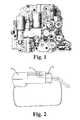
- FIG. 2A typical connection between the linear pressure solenoids and the wiring harness is shown in FIG. 2 .
- the plastic male plug 1 from the wiring harnessmates into the plastic female connector 2 on the linear pressure solenoid.
- the interlocking of the connection 3can be seen in FIGS. 2 and 3 as well.
- the locking features on the male plug and female connectorcan be further identified in FIG. 3 .
- the male plughas a one-way tapered protrusion 4 extending beyond the top plane of the plug.
- the female connector on the linear pressure solenoidhas a bridging feature 5 that intersects the protrusion 4 of the plug.
- the tapered edge of the protrusionpushes up the bridge allowing the plug to be inserted fully.
- the back edge of the protrusionmates flatly against the bridge 3 and therefore the plug cannot be easily removed.
- the locking featureprevents servicing of the linear pressure solenoids without breaking the bridging feature on the connector.
- a service technicianmay try to insert a small screwdriver under the bridge as shown in FIG. 4 . However, this often is ineffective because the amount of deflection required often breaks the bridge or permanently deforms the bridge. This renders the locking mechanism useless if the linear pressure solenoid is reused.
- a service technicianmay just cut the bridge off the connector as shown in FIG. 5 . Again, this prevents the plug from being secured in the connector if the linear pressure solenoid is reused.
- Various embodiments of the present inventionpertain to methods and apparatus to improve the repairability of used automatic transmissions.
- a method for securing such a connectionbe utilized that allows for servicing.
- a reusable retaining clipthat provide several useful aspects. Some allow for robustly securing electrical connections such as described in the AW 55-50. Other embodiments are reusable and therefore allow technicians to disengage the plug from the connector with ease. Yet other embodiments allow an effective “fix” for reusing connectors that have been broken. This permits the reuse of the connectors. In the case of the AW 55-50, as but one example, this feature enables the technician to reuse linear pressure solenoids that otherwise would be unusable.
- One aspect of the present inventionpertains to a method for repairing an electrical connector. Some embodiments include providing a used connector assembly having a first electrical connector, the second electrical connector, of an electrical wiring harness, and a retaining clip. Other embodiments include placing the clip over the mated first connector and second connector. Yet other embodiments include securing the placed clip to the mated first connector and second connector. Still other embodiments include compressing together the mated first connector and second connector with the secured clip.
- Another aspect of the present inventionpertains to an apparatus for an assembled multipiece electrical connector.
- Some embodimentsinclude a one piece body having a top wall and a pair of downwardly depending side walls, the body being fabricated from a resilient material, the side walls being elastically expandable in a direction from a free state to an expanded state, the distance between the inner faces of the body side walls in the free state being about the same or less than the corresponding external distance in the direction between opposing external sides of the assembled connector.
- the bodyincludes a removal feature useful for elastically expanding the side walls in the direction.
- Yet another aspect of the present inventionpertains to an apparatus for an assembled multipiece electrical connector.
- Some embodimentsinclude a one piece body having a top wall.
- Other embodimentsinclude a lateral wall downwardly depending from one of the lateral sides of the top wall, and an end wall each downwardly depending from the top wall, the lateral wall being elastically expandable in a lateral direction from a free state to an installed state.
- the body lateral wall in the free statebeing adapted and configured to fit over on opposing external sides of the assembled connector in the installed state, the height of the end wall being adapted and configured to limit end to end movement of the assembled connector relative to said body when installed.
- Still another aspect of the present inventionpertains to a method for repairing an automatic transmission.
- Some embodimentsinclude providing a used solenoid assembly having a first electrical connector mateable with the second electrical connector of an electrical wiring harness, and a retaining clip.
- Other embodimentsinclude placing the clip over the unmated first connector and second connector, and mating the first connector and second connector having the placed clip.
- Still other embodimentsinclude securing the placed clip to the mated first connector and second connector.
- Yet other embodimentsinclude compressing together the mated first connector and second connector with the secured clip.
- FIG. 1is a photograph of an Aisin Warner 55-50 front control valve body.
- FIG. 2is a photograph showing a typical engaged connection between linear pressure solenoid and wiring harness.
- FIG. 3is a photograph showing a typical connection between linear pressure solenoid and wiring harness before engagement.
- FIG. 4is a photograph of a typical method to remove plug.
- FIG. 5is a photograph showing a broken bridge after plug removal.
- FIG. 6is a CAD drawing of one embodiment of a retaining clip.
- FIG. 7is a CAD drawing of a front view of the retaining clip of FIG. 6 shown installed on an AW 55-50 linear pressure solenoid connector.
- FIG. 8is a CAD drawing of the back view of the apparatus of FIG. 7 .
- FIG. 9Ashows a top view of a connector according to one embodiment of the present invention.
- FIG. 9Bshows a rear view of the connector depicted in FIG. 9A .
- FIG. 9Cshows a side view of the connector depicted in FIG. 9A .
- FIG. 9Dshows another front view of the connector depicted in FIG. 9A .
- FIG. 10is a front, top right side perspective CAD representation of a retaining clip according to another embodiment of the present invention as installed on a connector.
- FIG. 11is a front, top, left side perspective representation of the retaining clip and connector of FIG. 10 .
- FIG. 12is a rear, top, right side perspective CAD representation of the retaining clip and connector of FIG. 10 .
- FIG. 13Ashows a top plan view of a retaining clip according to another embodiment of the present invention.
- FIG. 13Bshows a rear view of the retaining clip depicted in FIG. 13A .
- FIG. 13Cshows a side view of the retaining clip depicted in FIG. 13A .
- FIG. 13Dshows a front view of the retaining clip depicted in FIG. 13A .
- FIG. 14Ashows a top view of the retaining clip of FIGS. 13A-13D shown assembled over male and female connectors.
- FIG. 14Bshows a rear view of the retaining clip of FIGS. 13A-13D shown assembled over male and female connectors.
- FIG. 14Cshows a side view of the retaining clip of FIGS. 13A-13D shown assembled over male and female connectors.
- FIG. 14Dshows a front view of the retaining clip of FIG. 13A-13D shown assembled over male and female connectors.
- FIG. 14Eis a cross sectional representation of the assembly of FIGS. 14A-14D as taken along line A-A in FIG. 14C .
- NXX.XXrefers to an element that is the same as the non-prefixed element (XX.XX), except as shown and described.
- an element 1020 . 1would be the same as element 20 . 1 , except for those different features of element 1020 . 1 shown and described.
- common elements and common features of related elementsmay be drawn in the same manner in different figures, and/or use the same symbology in different figures. As such, it is not necessary to describe the features of 1020 . 1 and 20 . 1 that are the same, since these common features are apparent to a person of ordinary skill in the related field of technology. Further, it is understood that the features 1020 . 1 and 20 .
- NXX.XXmay include features compatible with other various embodiments (MXX.XX), as would be understood by those of ordinary skill in the art.
- This description conventionalso applies to the use of prime (′), double prime (′′), and triple prime (′′′) suffixed element numbers. Therefore, it is not necessary to describe the features of 20 . 1 , 20 . 1 ′, 20 . 1 ′′, and 20 . 1 ′′′ that are the same, since these common features are apparent to persons of ordinary skill in the related field of technology.
- Various embodiments of the present inventionpertain to spring-action retaining clips that fit closely around the external shape of an assembled electrical connector.
- the clipsare substantially open on one side, such that the clip can be installed on a preassembled multipiece electrical connector.
- a retaining clipprovides overall compression along the length of the mated male and female connector parts.
- such embodimentsfurther include one or more lateral side walls that limit any relative side-to-side motion of the connector assembly relative to the clip.
- Yet other embodimentspertain to a clip that clamps laterally around one or both pieces of the multipiece connector, and which further includes downwardly depending end walls that limit any axial relative motion between the connector and the installed clip to the amount of looseness or play between the connector assembly and the installed clip.
- Some embodimentsinclude one or more tabs or slots useful for reducing the axial or lateral clamping of the clip on the connector. When so loosened with a tool, the expanded clip (expanded either laterally and/or axially) can be removed, thus permitting disengagement of the pieces of the multipiece connector assembly.
- clips having a body with an internal shape that is complementary to the external shape of the assembled multipiece connectorWith such a complementary shape, various portions of the clip will correspond to various features of the assembled connector, as will be shown and described. However, it understood that having such a complementary shape generally refers to some features of the shape of the assembled connector, but not necessarily to all features of the external shape of the assembled connector.
- the apparatuscomprises of a thin metal spring clip formed in such a manner that the positive locking feature is maintained; yet it can be removed easily and reused according to the preferred method.
- a thin metal spring clipformed in such a manner that the positive locking feature is maintained; yet it can be removed easily and reused according to the preferred method.
- FIGS. 6-8One embodiment is shown in FIGS. 6-8 .
- the embodimentis designed for the AW 55-50 linear pressure solenoid, but can be adapted to other configurations as well.
- the reusable retaining clip 20includes several features.
- the clipincludes ears (or protruding fingers) 6 and 7 that slide under the plug 1 and the connector 2 on the opposing end.
- Retaining clip 20includes walls 10 - 1 and 10 - 2 that capture between them the respective outer faces of the assembled plug 1 and connector 2 , respectively.
- FIG. 9it can been seen that the free (unassembled) inner distance 8 . 1 between inner faces of walls 10 - 1 and 10 - 2 is adapted and configured to provide a snug level of compressive fit around plug 1 and connector 2 , and in yet other embodiments the distance 8 . 1 is adapted and configured to be a slightly loose fit around plug 1 and connector 2 .
- end walls 10 - 1 or 10 - 2can be adapted and configured to provide this snug fit by placing a slight convergent angle on one or both of the two end walls, such that they would converge at a point on the open side of the clip.
- the unassembled inner distance 8 . 1is a first, lesser distance proximate to the ears, and a slightly greater distance along the top (closed) side of the retaining clip.
- retaining clip 20is sufficiently elastic so that retaining clip 20 can be bent as it is being attached to the connection of plug 1 and retaining clip 20 .
- retaining clip 20can be removed by outwardly bending face 10 - 2 to relieve the snug compressive fit on the assembled connector, as well as to rotate ears 7 from the underneath side of connector 2 .
- the tab 8allows the clip to be installed and removed multiple times with ease.
- the ears 7 on either end of the clip 20provide lift-off retention of the retaining clip 20 on the assembled connector.
- a retaining featurecomprising a slot or aperture defined in a side wall of the clip that also permits insertion of a tool for a prying removal of the clip from the assembled connector.
- This centering feature 9is a centering feature 9 on the plug end that centers and aligns the legs 10 - 1 around the wires 11 of the plug 1 .
- This centering feature 9extends downwardly from the top wall of the body of retaining clip 20 , and contacts a corresponding external sidewall of the connector, and thus provides alignment and centering of the body of clip 20 in a direction generally orthogonal to the direction of the assembly of connecter parts plug 1 and connector 2 (the direction of assembly being generally coaxial with the depiction of the wires 11 in FIGS. 7 and 8 ).
- the side wall 10 of clip 20extends downwardly in a general U-shape, with the legs of the U extending on either side of wires 11 .
- plug 1 and connector 2is captured between the internal faces of side walls 10 - 1 and 10 - 2 , which in some embodiments is a capturing that applies axial compression to plug 1 and connector 2 .
- the wrap around fingers 6 and 7positively capture plug 1 and connector 2 , respectively, and further positively retains clip 20 on the assembly of plug 1 and connector 2 , such that clip 20 cannot be removed without bending the clip to eliminate contact between fingers 6 and 7 with the underside of plug 1 and connector 2 .
- Retaining clip 20further includes an end wall 10 - 2 that extends generally around the outer surface of connector 2 , and which further includes ears 7 that wrap around the front edge of connector 2 .
- connector 20includes one or more end walls 10 that depend downwardly from the top wall, and which prevent or limit (by interference) the axial or longitudinal movement of the assembled plug or connector relative to the clip. Any such relative motion is limited to the clearance or play between the ends of the assembled connector and plug and the inner faces of the one or more end walls.
- Another feature of the reusable clip(for cases such as the AW 55-50) is that the positive securing of the connection does not depend on any of the existing locking features. Therefore, the reusable clip can be used in place of the existing locking features if they are broken.
- Clip 20can be attached to the mated assembly of plug 1 and connector 2 , but in some embodiments is installed on the unconnected pair of the plug and the connector, by spreading apart (such as by bending) and expanding clip 20 .
- end walls 10 and their accompanying ears/fingersbend apart during preassembly alignment of the plug and connector.
- clip 20relaxes back toward its free state, with the fingers wrapping around corresponding edges of the plug or connector, and the plug and connector being held together in a state of compression in some embodiments, whereas in other embodiments the plug and connector are loosely held together between the relaxed end walls and relaxed fingers.
- the connector axial lengthis adapted and configured such that the fully installed distance between end walls 10 is greater than the free state distance, such that the installed clip 20 is in a state of bending and tension.
- the material for the reusable clipis any spring metal; however, a heat treated stainless steel or heat treated high carbon steel is preferred.
- the thickness of the reusable clipis about 0.020 inches. However, other configurations of material and thickness are expected to yield acceptable results as well. However, yet other embodiments of the present invention contemplate the use of any type of material that is suitable for the temperature and vibratory environment of the connector, including plastics.
- FIGS. 10-14present various views of a retaining clip 120 according to another embodiment of the present invention.
- Clip 20is similar in some aspects to clip 120 , as will be observable to a person having ordinary skill in this art.
- One difference between clips 20 and 120is that clip 120 clamps laterally around either plug 1 or connector 2 , whereas clip 20 clamps axially to the assembly of plug 1 and connector 2 .
- clip 120can be attached to an existing assembly of plug 1 within connector 2 , such that any potential separation of the plug from the connector is limited by the end walls of the clip.
- clip 120does not clamp to the connector, but instead defines a volumetric space equal to or greater than the volumetric space of the corresponding portions of the mated connector pieces, such that there can be some relative lateral and longitudinal movement of the clip relative to the connector pieces, but not so much movement as to permit disengagement of the two connector pieces.
- Retaining clip 120includes a pair of side walls 110 - 1 and 110 - 2 that hold between them the assembly of a plug 1 within a connector 2 .
- end wall 110 - 1includes a pair of legs 110 that extend downward in a U-shape around the wires 11 that fit within plug 1 .
- end wall 110 - 2extends downward around a portion of a sidewall of connector 2 .
- neither end walls 110 - 1 or 110 - 2include ears that wrap around the end faces of the plug or connector, respectively.
- the end features (axial features) of retaining clip 120provide abutments that prevent lengthwise sliding of the retaining clip relative to the assembly of plug 1 with connector 2 , but which may not provide lift-off retention of retaining clip 120 on the connector assembly.
- retaining clip 120includes a centering feature 109 that preferably provides a combination of lift-off retention, as well as lateral retention.
- centering feature 109includes a pair of opposing lateral side walls 109 - 1 and 109 - 2 that extend vertically across lateral faces of the corresponding sidewalls of connector 2 .
- FIG. 12shows that lateral side wall 109 - 2 extends at least partway vertically down an external lateral face of the sidewall of connector 2 .
- lateral wall 109 - 1preferably extends the entire vertical height of connector 2 , and preferably includes an ear 109 - 3 that wraps around the bottommost edge of connector 2 , and extends a short distance across the bottom face of connector 2 .
- Lateral wall 109 - 1preferably includes a removal feature or tab 108 that is adapted and configured to be actuated by common tools. Referring to FIGS. 12 and 14E , it can be seen that compression can be applied by pliers across the outer face of tab 108 and the top edge of lateral wall 109 - 2 . In so doing, lateral wall 109 - 1 can be bent outwardly (referring to FIG. 14E ) such that ear 109 - 3 no longer engages the bottom of connector 2 . Therefore, simple pliers can be used to momentarily compress tab 108 and remove clip 120 from the assembled connector. Also, a screwdriver can be inserted in the pocket shown in FIG. 14A and pressure applied against wall 108 to release the ear 109 - 3 .
- the apparatuspreferably includes a one piece body having a top wall and at least one, downwardly depending side wall.
- the side wallbeing elastically movable in a direction from a free state to an expanded state, the distance in the direction between the inner face of the body side wall and the inner face of an opposing vertical surface of the body in the free state being about the same or less than the corresponding external distance between opposing external features of the assembled connector.
- the bodyincluding a removal feature useful for elastically expanding said side walls for removal of the installed clip.
- the apparatuspreferably includes wherein said top wall and said side walls define a substantially open interior having a shape generally complementary to the external shape of portions of the assembled electrical connector.
- Another aspect of the present inventionpertains to a method for repairing an automatic transmission that includes a used solenoid assembly having a first electrical connector mateable with a second electrical connector.
- the methodpreferably includes placing a clip over the mated first connector and second connector.
- the methodpreferably includes compressing together the mated first connector and second connector with the secured clip.
- Yet another aspect of the present inventionpertains to an apparatus for an assembled multipiece electrical connector including a body having a top wall, a pair of lateral walls extending from opposite lateral sides of said top wall, and a pair of end walls extending from said top wall.
- the lateral wallsare elastically expandable in a lateral direction from a free state to an installed state, and configured to fit across opposing external sides of the assembled connector in the installed state.
- the end wallsare adapted and configured to limit end to end movement of the assembled connector relative to said body when installed.
- Still another aspect of the present inventionpertains to a method for securing together a first electrical connector mateable with the second electrical connector of an electrical wiring harness with a retaining clip.
- the methodpreferably includes placing the clip over the unmated first connector and second connector, and then mating the first connector and second connector having the placed clip.
- the methodpreferably includes securing the placed clip to the mated first connector and second connector, compressing together the mated first connector and second connector with the secured clip.
- the methodpreferably includes providing a used solenoid assembly having a first electrical connector mateable with the second electrical connector of an electrical wiring harness, and a retaining clip.
- the methodpreferably includes placing the clip over the unmated first connector and second connector.
- the methodpreferably includes mating the first connector and second connector having the placed clip.
- the methodpreferably includes securing the placed clip to the mated first connector and second connector.
- the methodpreferably includes compressing together the mated first connector and second connector with the secured clip.
- the body side wallsare first body side walls and the direction is a first direction, and which further comprises a pair of second body side walls downwardly extending from said top wall in a second direction orthogonal to said first direction.
- directionis a first direction and the separate pieces of the multipiece connector are assembled together in a second direction orthogonal to the first direction.
- the bodyfurther including a pair of opposing, downwardly depending lateral walls, and the minimum distance between the inner face of said lateral walls being substantially the same or less than the external distance across the lateral sides of the connector.
- one of the body end wallsincluding an opening for receiving therein the wires of the connector
- the bodyis a thin-walled structure fabricated from sheet metal or molded from plastic.
- the electrical connectoris a connector used with an automatic transmission.
- the inner surface of at least one of the body side wallshas a height about the same as the external height of the corresponding connector sidewall, and said at least one body side wall includes a finger that wraps around a corner of the connector side wall.
- the distance between the inner faces of the body side wallshas a minimum distance, the minimum distance being less than the external distance between opposing sidewalls of the connector.
- body side wallsare non-parallel, and the body side walls compress the connector when the body is placed over the connector.
- the removal featureis an outwardly extending tab adapted and configured for use to expand said body during removal or installation.
- the removal featureis slot in the body adapted and configured for insertion of a tool to expand said body during removal or installation.
- one of the side walls or one of the end walls of the clipis elastically bent out of the way to permit placement of the clip over the assembled multipiece connector, but after installation the clip provides relative clearance in the longitudinal and/or lateral directions, but not so much motion as to permit disengagement of the multiple pieces of the connector from one another.
- the clipcompresses the two pieces of the electrical connector, or prevents the two parts from separating, or limits the separation of the female connector from the male connector.
- the clipis biased to stay coupled to the connector.
- the clipdoes not define an enclosed volume.
- the connectorshave a generally rectangular outer shape.
- the clipincludes a tab or aperture to expand the length, or a tab or aperture to expand the width.
- the clipincludes means for expanding the free state of the clip body, including a tab, feature, slot, or aperture, usable by pliers, a screwdriver, or fingers.
Landscapes
- Engineering & Computer Science (AREA)
- Manufacturing & Machinery (AREA)
- Details Of Connecting Devices For Male And Female Coupling (AREA)
Abstract
Description
Claims (32)
Priority Applications (1)
| Application Number | Priority Date | Filing Date | Title |
|---|---|---|---|
| US14/707,340US9761986B2 (en) | 2012-03-21 | 2015-05-08 | Retaining clip for electrical connectors |
Applications Claiming Priority (5)
| Application Number | Priority Date | Filing Date | Title |
|---|---|---|---|
| US201261613808P | 2012-03-21 | 2012-03-21 | |
| US201361751147P | 2013-01-10 | 2013-01-10 | |
| US201361789381P | 2013-03-15 | 2013-03-15 | |
| US13/848,513US9048595B2 (en) | 2012-03-21 | 2013-03-21 | Retaining clip for electrical connectors |
| US14/707,340US9761986B2 (en) | 2012-03-21 | 2015-05-08 | Retaining clip for electrical connectors |
Related Parent Applications (1)
| Application Number | Title | Priority Date | Filing Date |
|---|---|---|---|
| US13/848,513ContinuationUS9048595B2 (en) | 2012-03-21 | 2013-03-21 | Retaining clip for electrical connectors |
Publications (2)
| Publication Number | Publication Date |
|---|---|
| US20150364852A1 US20150364852A1 (en) | 2015-12-17 |
| US9761986B2true US9761986B2 (en) | 2017-09-12 |
Family
ID=49209668
Family Applications (2)
| Application Number | Title | Priority Date | Filing Date |
|---|---|---|---|
| US13/848,513Expired - Fee RelatedUS9048595B2 (en) | 2012-03-21 | 2013-03-21 | Retaining clip for electrical connectors |
| US14/707,340ActiveUS9761986B2 (en) | 2012-03-21 | 2015-05-08 | Retaining clip for electrical connectors |
Family Applications Before (1)
| Application Number | Title | Priority Date | Filing Date |
|---|---|---|---|
| US13/848,513Expired - Fee RelatedUS9048595B2 (en) | 2012-03-21 | 2013-03-21 | Retaining clip for electrical connectors |
Country Status (2)
| Country | Link |
|---|---|
| US (2) | US9048595B2 (en) |
| CA (1) | CA2810863A1 (en) |
Cited By (1)
| Publication number | Priority date | Publication date | Assignee | Title |
|---|---|---|---|---|
| US10044142B1 (en)* | 2017-04-28 | 2018-08-07 | Valeo North America, Inc. | Connector locking holder |
Families Citing this family (4)
| Publication number | Priority date | Publication date | Assignee | Title |
|---|---|---|---|---|
| USD812015S1 (en) | 2016-09-30 | 2018-03-06 | Frederick E. Ryder | Extension cord connector lock |
| JP1659434S (en)* | 2019-06-04 | 2020-05-18 | ||
| USD922856S1 (en)* | 2020-01-10 | 2021-06-22 | Donna Stearns | Bracket |
| FR3118837B1 (en)* | 2021-01-08 | 2023-06-16 | Boyer Jean Raoul | Device for locking a cord connector on a bushing body. |
Citations (64)
| Publication number | Priority date | Publication date | Assignee | Title |
|---|---|---|---|---|
| US1310627A (en) | 1919-07-22 | Thomas eraitcis mcevilly | ||
| US2406567A (en) | 1945-03-10 | 1946-08-27 | Aloysius J Schueneman | Holder for cords of electrical connectors |
| US2720633A (en) | 1953-06-12 | 1955-10-11 | Oscar E Westberg | Clamp for electrical connectors |
| US2753536A (en) | 1953-07-27 | 1956-07-03 | Tjader Hugo | Clamps for holding electric connectors together |
| US2761109A (en) | 1954-01-19 | 1956-08-28 | Hacker Arnold | Safety-type clamp for electric plug and socket |
| US3030601A (en) | 1958-10-30 | 1962-04-17 | Donald R Krebs | Electric cord connector |
| US3183470A (en) | 1964-01-09 | 1965-05-11 | Leigh E Hale | Electric connector locking means |
| US3383639A (en) | 1966-04-06 | 1968-05-14 | Fred H. Anderson | Cord extension coupling clamps |
| US3475716A (en) | 1967-12-08 | 1969-10-28 | Miller Electric Co | Retainer for electric cord connectors |
| US3609638A (en) | 1970-06-03 | 1971-09-28 | John J Darrey | Extension cord coupling clamp assembly |
| US3824525A (en) | 1972-09-11 | 1974-07-16 | Amp Inc | Connector latch assembly |
| US3881753A (en) | 1973-06-04 | 1975-05-06 | Michael E Bochory | Fastener mechanism |
| US3926497A (en) | 1974-03-12 | 1975-12-16 | Du Pont | Connector shroud and assembly |
| USD244612S (en) | 1976-01-12 | 1977-06-07 | International Telephone And Telegraph Corporation | Electrical connector retaining clip |
| US4076204A (en) | 1976-11-16 | 1978-02-28 | Minnesota Mining And Manufacturing Company | Retaining clip |
| US4183603A (en) | 1978-06-09 | 1980-01-15 | Robert Donarummo | Extension cord lock |
| US4221449A (en) | 1979-05-07 | 1980-09-09 | Shugart Jr James F | Locking device for electric cords |
| USD269065S (en) | 1980-12-19 | 1983-05-24 | Hough Jr W Colton | Cord lock device |
| USD283441S (en) | 1983-04-08 | 1986-04-15 | Abbott Laboratories | Intravenous administration locking device |
| US4690476A (en) | 1986-10-30 | 1987-09-01 | Jali Morgenrath | Electrical connector securing system |
| US4773874A (en) | 1987-08-26 | 1988-09-27 | Kopeski Jr Michael J | Power cord clip |
| US4826486A (en) | 1986-12-10 | 1989-05-02 | Dale Medical Products, Inc. | IV connector lock and stabilizer |
| US4832618A (en) | 1988-02-29 | 1989-05-23 | Gunderson Jon R | Electric cord lock |
| USD302304S (en) | 1986-09-10 | 1989-07-18 | Baxter International Inc. | Secondary set lock to secure a secondary intravenous set line to a primary intravenous set line |
| US4925399A (en) | 1988-06-06 | 1990-05-15 | Dean Bosworth | Cord clip |
| US4940423A (en) | 1987-12-15 | 1990-07-10 | Honda Giken Kogyo Kabushiki Kaisha | Connector apparatus |
| US4997421A (en) | 1986-12-10 | 1991-03-05 | Dale Medical Products, Inc. | IV connector lock and stabilizer |
| USD315719S (en) | 1988-06-27 | 1991-03-26 | Motorola, Inc. | Quick release electrical connector clip or similar article |
| US5129839A (en) | 1991-11-20 | 1992-07-14 | Doskocil Manufacturing Company, Inc. | Extension cord connection housing |
| US5174023A (en) | 1990-06-25 | 1992-12-29 | Mcdonnell Douglas Corporation | Method for repairing an electrical connector |
| US5179044A (en) | 1991-11-27 | 1993-01-12 | Muromachi Paul N | Securing device for male plug/female socket connectors |
| GB2257572A (en) | 1991-07-06 | 1993-01-13 | Unisys Corp | Retaining mated electrical connectors in engagement |
| US5211573A (en) | 1992-01-02 | 1993-05-18 | Cross Andrew L | Electrical cord coupling |
| US5445528A (en) | 1994-05-31 | 1995-08-29 | The Whitaker Corporation | Electrical connector with improved mounting |
| US5551888A (en) | 1995-02-03 | 1996-09-03 | Rhodes, Sr.; Rockney J. | Surface-piercing electrical connector protector |
| US5573420A (en) | 1994-12-20 | 1996-11-12 | Grosswendt; Patrick J. | Electrical cord and electrical plug securer |
| USD393862S (en) | 1996-04-18 | 1998-04-28 | Portia Industries Pty Ltd | Telephone connector |
| US5769646A (en) | 1995-07-25 | 1998-06-23 | Dell U.S.A., L.P. | Integrated electrical connector guard device for use in a personal computer |
| US5839920A (en) | 1995-12-06 | 1998-11-24 | The Whitaker Corporation | Electrical connector seal |
| US6036525A (en) | 1998-11-02 | 2000-03-14 | Alfis, Iii; Michael V. | Sealable enclosure for electrical cable connectors |
| US6050844A (en) | 1998-04-22 | 2000-04-18 | Johnson; Dee Lynn | Electrical connector with channels for wires |
| US6171146B1 (en) | 1998-02-19 | 2001-01-09 | Delphi Technologies, Inc. | Repair method for dual lock multi-row electrical connector system |
| US6254048B1 (en) | 1999-08-30 | 2001-07-03 | Alliedsignal Truck Brake Systems Company | Solenoid clamp |
| US6257924B1 (en) | 2000-08-22 | 2001-07-10 | International Business Machines Corporation | Stacked electrical connector assembly protector |
| US20010046813A1 (en) | 2000-03-30 | 2001-11-29 | Greenside Michael J. | Protective cover for a printed circuit board electrical connector |
| US6350151B1 (en) | 2000-02-01 | 2002-02-26 | Adc Telecommunications, Inc. | Cable management apparatus for an outlet box |
| US6435891B1 (en) | 1999-10-28 | 2002-08-20 | Tyco Electronics Corporation | Mechanically assisted blind mate electrical connector |
| US6500027B1 (en) | 1997-01-28 | 2002-12-31 | Ludovicus Cornelis Van Der Sanden | Seal for an electrical connector, method for manufacturing a seal and use of a seal |
| USD474156S1 (en) | 2002-02-22 | 2003-05-06 | Antonios Vournou | Power cord connector |
| US6585534B2 (en)* | 1998-08-20 | 2003-07-01 | Intel Corporation | Retention mechanism for an electrical assembly |
| US6741776B2 (en)* | 2000-06-26 | 2004-05-25 | The Furukawa Electric Co., Ltd. | Optical waveguide module optically connected with an optical fiber |
| US6790060B1 (en) | 2002-12-24 | 2004-09-14 | Delta Electronics, Inc. | Storing lid for electronic devices |
| US6905353B2 (en) | 2003-03-07 | 2005-06-14 | Hon Hai Precision Ind. Co., Ltd. | Electrical connector assembly with pick up cap protecting contacts |
| US7101215B2 (en) | 2004-03-31 | 2006-09-05 | Hewlett-Packard Development Company, L.P. | Cable plug retention clip |
| WO2007012134A1 (en) | 2005-07-27 | 2007-02-01 | Gerard Anthony Harrington | Electric cord connection housing unit |
| US7354297B2 (en) | 2004-02-17 | 2008-04-08 | Toyota Jidosha Kabushiki Kaisha | Connector fixing structure |
| US7407405B1 (en) | 2006-10-02 | 2008-08-05 | Slenczka Thomas J | Plug connection device |
| US7443661B2 (en) | 2004-07-02 | 2008-10-28 | Hong Fu Jin Precision Industry (Shenzhen) Co., Ltd. | Protection device for connectors |
| US7495900B2 (en) | 2005-06-10 | 2009-02-24 | Hong Fu Jin Precision Industry (Shen Zhen) Co., Ltd. | Protection mechanism for connectors |
| USD593037S1 (en) | 2007-07-26 | 2009-05-26 | Shien-Tang Tseng Joseph | latch of cable connector for portable media player |
| US7628615B2 (en) | 2007-08-21 | 2009-12-08 | Hon Hai Precision Ind. Co., Ltd | Electrical connector assembly having improved pick up cap |
| US7804691B1 (en) | 2006-05-18 | 2010-09-28 | Utility Associates, Inc. | Assembly for protecting PC cards and peripheral connectors |
| US7922534B2 (en) | 2006-01-19 | 2011-04-12 | Molex Incorporated | Socket connector |
| US8100698B2 (en) | 2010-01-19 | 2012-01-24 | Hon Hai Precision Ind. Co., Ltd. | Electrical connector with removable housing |
- 2013
- 2013-03-21CACA2810863Apatent/CA2810863A1/ennot_activeAbandoned
- 2013-03-21USUS13/848,513patent/US9048595B2/ennot_activeExpired - Fee Related
- 2015
- 2015-05-08USUS14/707,340patent/US9761986B2/enactiveActive
Patent Citations (64)
| Publication number | Priority date | Publication date | Assignee | Title |
|---|---|---|---|---|
| US1310627A (en) | 1919-07-22 | Thomas eraitcis mcevilly | ||
| US2406567A (en) | 1945-03-10 | 1946-08-27 | Aloysius J Schueneman | Holder for cords of electrical connectors |
| US2720633A (en) | 1953-06-12 | 1955-10-11 | Oscar E Westberg | Clamp for electrical connectors |
| US2753536A (en) | 1953-07-27 | 1956-07-03 | Tjader Hugo | Clamps for holding electric connectors together |
| US2761109A (en) | 1954-01-19 | 1956-08-28 | Hacker Arnold | Safety-type clamp for electric plug and socket |
| US3030601A (en) | 1958-10-30 | 1962-04-17 | Donald R Krebs | Electric cord connector |
| US3183470A (en) | 1964-01-09 | 1965-05-11 | Leigh E Hale | Electric connector locking means |
| US3383639A (en) | 1966-04-06 | 1968-05-14 | Fred H. Anderson | Cord extension coupling clamps |
| US3475716A (en) | 1967-12-08 | 1969-10-28 | Miller Electric Co | Retainer for electric cord connectors |
| US3609638A (en) | 1970-06-03 | 1971-09-28 | John J Darrey | Extension cord coupling clamp assembly |
| US3824525A (en) | 1972-09-11 | 1974-07-16 | Amp Inc | Connector latch assembly |
| US3881753A (en) | 1973-06-04 | 1975-05-06 | Michael E Bochory | Fastener mechanism |
| US3926497A (en) | 1974-03-12 | 1975-12-16 | Du Pont | Connector shroud and assembly |
| USD244612S (en) | 1976-01-12 | 1977-06-07 | International Telephone And Telegraph Corporation | Electrical connector retaining clip |
| US4076204A (en) | 1976-11-16 | 1978-02-28 | Minnesota Mining And Manufacturing Company | Retaining clip |
| US4183603A (en) | 1978-06-09 | 1980-01-15 | Robert Donarummo | Extension cord lock |
| US4221449A (en) | 1979-05-07 | 1980-09-09 | Shugart Jr James F | Locking device for electric cords |
| USD269065S (en) | 1980-12-19 | 1983-05-24 | Hough Jr W Colton | Cord lock device |
| USD283441S (en) | 1983-04-08 | 1986-04-15 | Abbott Laboratories | Intravenous administration locking device |
| USD302304S (en) | 1986-09-10 | 1989-07-18 | Baxter International Inc. | Secondary set lock to secure a secondary intravenous set line to a primary intravenous set line |
| US4690476A (en) | 1986-10-30 | 1987-09-01 | Jali Morgenrath | Electrical connector securing system |
| US4997421A (en) | 1986-12-10 | 1991-03-05 | Dale Medical Products, Inc. | IV connector lock and stabilizer |
| US4826486A (en) | 1986-12-10 | 1989-05-02 | Dale Medical Products, Inc. | IV connector lock and stabilizer |
| US4773874A (en) | 1987-08-26 | 1988-09-27 | Kopeski Jr Michael J | Power cord clip |
| US4940423A (en) | 1987-12-15 | 1990-07-10 | Honda Giken Kogyo Kabushiki Kaisha | Connector apparatus |
| US4832618A (en) | 1988-02-29 | 1989-05-23 | Gunderson Jon R | Electric cord lock |
| US4925399A (en) | 1988-06-06 | 1990-05-15 | Dean Bosworth | Cord clip |
| USD315719S (en) | 1988-06-27 | 1991-03-26 | Motorola, Inc. | Quick release electrical connector clip or similar article |
| US5174023A (en) | 1990-06-25 | 1992-12-29 | Mcdonnell Douglas Corporation | Method for repairing an electrical connector |
| GB2257572A (en) | 1991-07-06 | 1993-01-13 | Unisys Corp | Retaining mated electrical connectors in engagement |
| US5129839A (en) | 1991-11-20 | 1992-07-14 | Doskocil Manufacturing Company, Inc. | Extension cord connection housing |
| US5179044A (en) | 1991-11-27 | 1993-01-12 | Muromachi Paul N | Securing device for male plug/female socket connectors |
| US5211573A (en) | 1992-01-02 | 1993-05-18 | Cross Andrew L | Electrical cord coupling |
| US5445528A (en) | 1994-05-31 | 1995-08-29 | The Whitaker Corporation | Electrical connector with improved mounting |
| US5573420A (en) | 1994-12-20 | 1996-11-12 | Grosswendt; Patrick J. | Electrical cord and electrical plug securer |
| US5551888A (en) | 1995-02-03 | 1996-09-03 | Rhodes, Sr.; Rockney J. | Surface-piercing electrical connector protector |
| US5769646A (en) | 1995-07-25 | 1998-06-23 | Dell U.S.A., L.P. | Integrated electrical connector guard device for use in a personal computer |
| US5839920A (en) | 1995-12-06 | 1998-11-24 | The Whitaker Corporation | Electrical connector seal |
| USD393862S (en) | 1996-04-18 | 1998-04-28 | Portia Industries Pty Ltd | Telephone connector |
| US6500027B1 (en) | 1997-01-28 | 2002-12-31 | Ludovicus Cornelis Van Der Sanden | Seal for an electrical connector, method for manufacturing a seal and use of a seal |
| US6171146B1 (en) | 1998-02-19 | 2001-01-09 | Delphi Technologies, Inc. | Repair method for dual lock multi-row electrical connector system |
| US6050844A (en) | 1998-04-22 | 2000-04-18 | Johnson; Dee Lynn | Electrical connector with channels for wires |
| US6585534B2 (en)* | 1998-08-20 | 2003-07-01 | Intel Corporation | Retention mechanism for an electrical assembly |
| US6036525A (en) | 1998-11-02 | 2000-03-14 | Alfis, Iii; Michael V. | Sealable enclosure for electrical cable connectors |
| US6254048B1 (en) | 1999-08-30 | 2001-07-03 | Alliedsignal Truck Brake Systems Company | Solenoid clamp |
| US6435891B1 (en) | 1999-10-28 | 2002-08-20 | Tyco Electronics Corporation | Mechanically assisted blind mate electrical connector |
| US6350151B1 (en) | 2000-02-01 | 2002-02-26 | Adc Telecommunications, Inc. | Cable management apparatus for an outlet box |
| US20010046813A1 (en) | 2000-03-30 | 2001-11-29 | Greenside Michael J. | Protective cover for a printed circuit board electrical connector |
| US6741776B2 (en)* | 2000-06-26 | 2004-05-25 | The Furukawa Electric Co., Ltd. | Optical waveguide module optically connected with an optical fiber |
| US6257924B1 (en) | 2000-08-22 | 2001-07-10 | International Business Machines Corporation | Stacked electrical connector assembly protector |
| USD474156S1 (en) | 2002-02-22 | 2003-05-06 | Antonios Vournou | Power cord connector |
| US6790060B1 (en) | 2002-12-24 | 2004-09-14 | Delta Electronics, Inc. | Storing lid for electronic devices |
| US6905353B2 (en) | 2003-03-07 | 2005-06-14 | Hon Hai Precision Ind. Co., Ltd. | Electrical connector assembly with pick up cap protecting contacts |
| US7354297B2 (en) | 2004-02-17 | 2008-04-08 | Toyota Jidosha Kabushiki Kaisha | Connector fixing structure |
| US7101215B2 (en) | 2004-03-31 | 2006-09-05 | Hewlett-Packard Development Company, L.P. | Cable plug retention clip |
| US7443661B2 (en) | 2004-07-02 | 2008-10-28 | Hong Fu Jin Precision Industry (Shenzhen) Co., Ltd. | Protection device for connectors |
| US7495900B2 (en) | 2005-06-10 | 2009-02-24 | Hong Fu Jin Precision Industry (Shen Zhen) Co., Ltd. | Protection mechanism for connectors |
| WO2007012134A1 (en) | 2005-07-27 | 2007-02-01 | Gerard Anthony Harrington | Electric cord connection housing unit |
| US7922534B2 (en) | 2006-01-19 | 2011-04-12 | Molex Incorporated | Socket connector |
| US7804691B1 (en) | 2006-05-18 | 2010-09-28 | Utility Associates, Inc. | Assembly for protecting PC cards and peripheral connectors |
| US7407405B1 (en) | 2006-10-02 | 2008-08-05 | Slenczka Thomas J | Plug connection device |
| USD593037S1 (en) | 2007-07-26 | 2009-05-26 | Shien-Tang Tseng Joseph | latch of cable connector for portable media player |
| US7628615B2 (en) | 2007-08-21 | 2009-12-08 | Hon Hai Precision Ind. Co., Ltd | Electrical connector assembly having improved pick up cap |
| US8100698B2 (en) | 2010-01-19 | 2012-01-24 | Hon Hai Precision Ind. Co., Ltd. | Electrical connector with removable housing |
Non-Patent Citations (3)
| Title |
|---|
| U.S. Appl. No. 13/848,513, Nonfinal Office Action, 10 pages Aug. 18, 2014. |
| U.S. Appl. No. 13/848,513, Notice of Allowance, 12 pages Feb. 3, 2015. |
| U.S. Appl. No. 13/848,513, Response to NF Office Action, 19 pages Nov. 18, 2014. |
Cited By (1)
| Publication number | Priority date | Publication date | Assignee | Title |
|---|---|---|---|---|
| US10044142B1 (en)* | 2017-04-28 | 2018-08-07 | Valeo North America, Inc. | Connector locking holder |
Also Published As
| Publication number | Publication date |
|---|---|
| US9048595B2 (en) | 2015-06-02 |
| CA2810863A1 (en) | 2013-09-21 |
| US20150364852A1 (en) | 2015-12-17 |
| US20130252460A1 (en) | 2013-09-26 |
Similar Documents
| Publication | Publication Date | Title |
|---|---|---|
| US9761986B2 (en) | Retaining clip for electrical connectors | |
| US9065207B2 (en) | Locking electrical receptacle | |
| EP2930796B1 (en) | Connector with vibratory connection feedback | |
| AU2012305707B2 (en) | Secure electrical receptacle | |
| CN1653650B (en) | Connection terminal | |
| EP2899813A1 (en) | Connector | |
| KR101845638B1 (en) | Unthreaded terminal strip | |
| JP2015228330A (en) | connector | |
| WO2016156385A1 (en) | Angle connector | |
| CN114258614A (en) | female terminal | |
| US20180301825A1 (en) | Rail terminal assembling structure | |
| CN105284011A (en) | Female terminal | |
| US20070202744A1 (en) | Flat Blade Jack | |
| WO2007131537A1 (en) | Connector of flat conductors | |
| JP2007507842A (en) | Electrical connector with quick disconnect system | |
| JP2007507842A6 (en) | Electrical connector with quick disconnect system | |
| JP2008180337A (en) | Snap-fit structure and insertion load reduction method | |
| CN109716591B (en) | Connect terminal blocks, electrical equipment | |
| US8900003B2 (en) | Connector | |
| JP2006040818A (en) | Connector | |
| JP2011070843A (en) | Female side terminal fitting | |
| WO2012086545A1 (en) | Connector | |
| US10581182B2 (en) | Spring clip electrically connecting a wire and electronic component | |
| CN104620445A (en) | Locking mechanism for molded resin component | |
| JP2011119108A (en) | Female terminal fitting |
Legal Events
| Date | Code | Title | Description |
|---|---|---|---|
| AS | Assignment | Owner name:ADVANCED POWERTRAIN ENGINEERING, LLC, INDIANA Free format text:ASSIGNMENT OF ASSIGNORS INTEREST;ASSIGNOR:FATHAUER, PAUL;REEL/FRAME:035636/0186 Effective date:20130409 | |
| STCF | Information on status: patent grant | Free format text:PATENTED CASE | |
| AS | Assignment | Owner name:ADVANCED POWERTRAIN ENGINEERING, LLC, INDIANA Free format text:ASSIGNMENT OF ASSIGNORS INTEREST;ASSIGNOR:FATHAUER, PAUL;REEL/FRAME:053227/0878 Effective date:20200716 | |
| AS | Assignment | Owner name:SONNAX TRANSMISSION COMPANY, VERMONT Free format text:ASSIGNMENT OF ASSIGNORS INTEREST;ASSIGNOR:ADVANCED POWERTRAIN ENGINEERING, LLC;REEL/FRAME:053673/0496 Effective date:20200824 | |
| MAFP | Maintenance fee payment | Free format text:PAYMENT OF MAINTENANCE FEE, 4TH YR, SMALL ENTITY (ORIGINAL EVENT CODE: M2551); ENTITY STATUS OF PATENT OWNER: SMALL ENTITY Year of fee payment:4 | |
| FEPP | Fee payment procedure | Free format text:ENTITY STATUS SET TO UNDISCOUNTED (ORIGINAL EVENT CODE: BIG.); ENTITY STATUS OF PATENT OWNER: LARGE ENTITY | |
| MAFP | Maintenance fee payment | Free format text:PAYMENT OF MAINTENANCE FEE UNDER 1.28(C) (ORIGINAL EVENT CODE: M1559); ENTITY STATUS OF PATENT OWNER: LARGE ENTITY | |
| FEPP | Fee payment procedure | Free format text:PETITION RELATED TO MAINTENANCE FEES GRANTED (ORIGINAL EVENT CODE: PTGR); ENTITY STATUS OF PATENT OWNER: LARGE ENTITY | |
| FEPP | Fee payment procedure | Free format text:MAINTENANCE FEE REMINDER MAILED (ORIGINAL EVENT CODE: REM.); ENTITY STATUS OF PATENT OWNER: LARGE ENTITY |