US9760603B2 - Method and system to provide composite view of data from disparate data sources - Google Patents
Method and system to provide composite view of data from disparate data sourcesDownload PDFInfo
- Publication number
- US9760603B2 US9760603B2US14/709,209US201514709209AUS9760603B2US 9760603 B2US9760603 B2US 9760603B2US 201514709209 AUS201514709209 AUS 201514709209AUS 9760603 B2US9760603 B2US 9760603B2
- Authority
- US
- United States
- Prior art keywords
- data
- subview
- view
- user
- data sources
- Prior art date
- Legal status (The legal status is an assumption and is not a legal conclusion. Google has not performed a legal analysis and makes no representation as to the accuracy of the status listed.)
- Expired - Lifetime, expires
Links
Images


Classifications
- G06F17/30451—
- G—PHYSICS
- G06—COMPUTING OR CALCULATING; COUNTING
- G06F—ELECTRIC DIGITAL DATA PROCESSING
- G06F16/00—Information retrieval; Database structures therefor; File system structures therefor
- G06F16/20—Information retrieval; Database structures therefor; File system structures therefor of structured data, e.g. relational data
- G06F16/24—Querying
- G06F16/245—Query processing
- G06F16/2453—Query optimisation
- G06F16/24534—Query rewriting; Transformation
- G06F16/24535—Query rewriting; Transformation of sub-queries or views
- G—PHYSICS
- G06—COMPUTING OR CALCULATING; COUNTING
- G06F—ELECTRIC DIGITAL DATA PROCESSING
- G06F16/00—Information retrieval; Database structures therefor; File system structures therefor
- G06F16/10—File systems; File servers
- G06F16/14—Details of searching files based on file metadata
- G06F16/148—File search processing
- G—PHYSICS
- G06—COMPUTING OR CALCULATING; COUNTING
- G06F—ELECTRIC DIGITAL DATA PROCESSING
- G06F16/00—Information retrieval; Database structures therefor; File system structures therefor
- G06F16/10—File systems; File servers
- G06F16/14—Details of searching files based on file metadata
- G06F16/156—Query results presentation
- G—PHYSICS
- G06—COMPUTING OR CALCULATING; COUNTING
- G06F—ELECTRIC DIGITAL DATA PROCESSING
- G06F16/00—Information retrieval; Database structures therefor; File system structures therefor
- G06F16/20—Information retrieval; Database structures therefor; File system structures therefor of structured data, e.g. relational data
- G06F16/24—Querying
- G06F16/242—Query formulation
- G06F16/2433—Query languages
- G06F16/244—Grouping and aggregation
- G—PHYSICS
- G06—COMPUTING OR CALCULATING; COUNTING
- G06F—ELECTRIC DIGITAL DATA PROCESSING
- G06F16/00—Information retrieval; Database structures therefor; File system structures therefor
- G06F16/20—Information retrieval; Database structures therefor; File system structures therefor of structured data, e.g. relational data
- G06F16/24—Querying
- G06F16/248—Presentation of query results
- G—PHYSICS
- G06—COMPUTING OR CALCULATING; COUNTING
- G06F—ELECTRIC DIGITAL DATA PROCESSING
- G06F16/00—Information retrieval; Database structures therefor; File system structures therefor
- G06F16/20—Information retrieval; Database structures therefor; File system structures therefor of structured data, e.g. relational data
- G06F16/25—Integrating or interfacing systems involving database management systems
- G06F16/256—Integrating or interfacing systems involving database management systems in federated or virtual databases
- G—PHYSICS
- G06—COMPUTING OR CALCULATING; COUNTING
- G06F—ELECTRIC DIGITAL DATA PROCESSING
- G06F16/00—Information retrieval; Database structures therefor; File system structures therefor
- G06F16/50—Information retrieval; Database structures therefor; File system structures therefor of still image data
- G06F16/53—Querying
- G06F16/532—Query formulation, e.g. graphical querying
- G—PHYSICS
- G06—COMPUTING OR CALCULATING; COUNTING
- G06F—ELECTRIC DIGITAL DATA PROCESSING
- G06F16/00—Information retrieval; Database structures therefor; File system structures therefor
- G06F16/90—Details of database functions independent of the retrieved data types
- G06F16/903—Querying
- G06F16/9038—Presentation of query results
- G06F17/30106—
- G06F17/30112—
- G06F17/30277—
- G06F17/30412—
- G06F17/30554—
- G06F17/30566—
- G06F17/30991—
Definitions
- the inventionrelates in general to data management, and more particularly, to managing, aggregating and displaying data from disparate sources.
- relating data between data repositoriesis a manually intensive process.
- a personqueries the Oracle database with the customer name in the “CUSNAME” field to obtain sales data for the customer and queries the SAP database with the customer name in the “CUSTOMERNAME” field to obtain the address of the customer.
- obtaining data from a wide variety of data repositoriesis a time consuming task.
- coalescing and analyzing this datais an even more difficult task, and displaying the results of these data mining efforts more difficult still.
- Systems and methods for defining a composite view and using the definition of the composite view to obtain, aggregate, analyze, and present data from a variety of data sources to a usermay allow for the definition of a visual framework to aggregate and display related data.
- This visual framework, or composite viewmay in turn be composed of a master view and a set of subviews, each of which may display data collected from a particular data source according to a particular format.
- a usermay indicate a criterion.
- each of these subviewsgathers data from the data source with which it is associated.
- Each subviewthen presents the acquired data in the composite view according to the definition of the subview.
- the composite viewcan present associated data from a variety of data sources based solely on the user's interaction with the master view.
- a criterionis determined from a selection in a master view and is passed from a master view to a set of subviews of the master view based on a mapping of a field in the master view to a field in each of the subviews.
- Each of the subviewscan then be formed using data obtained from a data source using the criterion.
- a criterionis passed from a subview of the master view to its subviews based on a mapping of a field in the subview to a field in each of its subviews.
- Each of these subviewscan then be formed using the criterion using data obtained from a data source using the criterion.
- the data sourcesmay be in a variety of formats.
- FIG. 1includes an illustration of an embodiment of an architecture for implementing the present invention.
- FIG. 2includes a block diagram of an embodiment of a composite view.
- FIG. 3includes a flow diagram for one embodiment of creating a composite view.
- FIGS. 4-12include one embodiment of an interface for defining a data model.
- FIG. 13includes a representation of one embodiment of an interface for displaying defined components.
- FIGS. 14-19include a representation of one embodiment of an interface for defining a view.
- FIG. 20includes a representation of one embodiment of an interface for displaying defined components.
- FIGS. 21-27include a representation of an interface for editing a view, including defining subviews.
- FIGS. 28-34include a representation of one embodiment of an interface for defining and editing a view to be used as a master view, including defining subviews.
- FIGS. 35-37include a representation of one embodiment of interacting with a composite view.
- viewis intended to mean a visual framework or a definition for presenting data. This view may include a number of “subviews” which in themselves may be views.
- the term “subview” in this contextis intended to mean a view defined with respect to another view. For example, if a view is defined to include a second view, the second view may be labeled a “subview” of the first view and the first view a “parent view” of the second view, however this second view may contain a third view, thus the third view would be a “subview” of the second view and the second view a “parent view” of the third view.
- a “composite view”is intended to mean any view (referred to as the “master view”) that includes one or more subviews.
- data modelis intended to mean a set of data based on data from one or more data sources. This set of data may be obtained directly from a data source, may be the result of the application of one or more rules to data from the data source, may result from sending data from the data source to a web service and receiving a response which is contained in the data model, etc.
- data sourceis intended to mean any type of repository for data, including databases and the like.
- These systems and methodsmay allow for the definition of a visual framework to aggregate and display related data.
- This visual framework, or composite viewmay in turn be composed of a master view and a set of subviews, each of which may display data collected from a particular data source according to a particular format.
- Each of these viewsmay be based on a data model, and the data model, in turn, based on a data source.
- Using the master viewa user may indicate a criterion.
- each of these subviewsgathers data from the data model on which it is based, the data model having access to this information from the data source with which it is associated.
- Each subviewthen presents the acquired data in the composite view according to the definition of the subview.
- the composite viewcan present associated data from a variety of data sources based solely on the user's interaction with the master view.
- the computer-executable instructionsmay be lines of assembly code or compiled C ++ , Java, or other language code. Other architectures may be used. Additionally, a computer program or its software components with such code may be embodied in more than one data processing system readable medium in more than one computer.
- FIG. 1includes a block diagram of an exemplary architecture for an embodiment of the present invention.
- Data sources 100 , 102 , 104may be databases or any other type of repositories for data as are known in the art.
- data source 100may be a SAP database
- data source 102an Oracle database
- data source 104may be a web service capable of returning data in response to an inquiry.
- Each of these data sourcesmay store data according to a variety of fields as is known in the art.
- Data models 110 , 112 , 114are sets of data based on one or more data sources 100 , 102 , 104 , and may consist of data taken directly from data sources 100 , 102 , 104 , from rules applied to data taken from data sources 100 , 102 , 104 or any other way of manipulating data in data sources 100 , 102 , 104 , such as sending data from data sources 100 , 102 , 104 to a web site, receiving data in return and including this returned data in the data model.
- Data models 110 , 112 , 114each contain a set of fields. Each of these fields corresponds directly to a field within the data source 100 , 102 , 104 on which data model 110 , 112 , 114 is based, or, is a new field defined during definition of data model 110 , 112 , 114 .
- data models 110 and 112may be based on data source 100 which is an SAP database, while data model 114 may be based on data source 102 , an Oracle database.
- data models 110 , 112 , 114information from varying data sources 100 , 102 , 104 may be represented and/or stored in a substantially similar format, regardless of the format of the underlying source of that data.
- Views 120 , 122 , 124 , 126are based on data models 110 , 112 , 114 and define a visual framework for presenting data contained in the data model on which view 120 , 122 , 124 , 126 is based.
- Views 120 , 122 , 124 , 126are usually displayed as a chart, a form, or a report. Charts graphically present data in the data model associated with the view, forms may display data and allow a view to contain other views and reports may present a set of the data in the associated data model in tabular format.
- Views 120 , 122 , 124 , 126are based on a set of fields, each field within each view 120 , 122 , 124 , 126 corresponding to a field in data model 110 , 112 , 114 on which view 120 , 122 , 124 , 126 is based.
- One or more of these fields in each view 120 , 122 , 124 , 126can be designated as searchable by criterion, thus, a criterion can be presented to a view and the view can search the designated field for the criteria. If the criterion is found, data associated with that criterion is presented in the view.
- view 120is based on data model 110
- view 122is based on data model 112
- view 124is based on data model 114
- view 126is based on data model 114 .
- FIG. 2A block diagram of an exemplary definition for a composite view is illustrated in FIG. 2 .
- Composite view 200is comprised of a number of views 210 , 220 , 230 , 240 . These views 210 , 220 , 230 , 240 may be linked together so that interaction with one of the views 210 , 220 , 230 , 240 drives the display of data in the other views 210 , 220 , 230 , 240 .
- one of these views 210is a master view
- view 220is a subview of master view 210
- views 230 and 240are subviews of view 220 .
- a usermay alter the data displayed in each of the subviews 220 , 230 , 240 .
- a field of master view 210is mapped to a field of subview 220 , with this field of subview 220 operable to be searched by a criterion.
- a field of subview 220may be mapped to a field of subview 230 and a field of subview 240 , with both the field of subview 230 and the field of subview 240 operable to be searched by a criterion.
- the fields in subviews 220 , 230 and 240may have been designated as searchable by a criterion during the definition of their respective subviews 220 , 230 , 240 .
- composite view 200may drive the data displayed in views 220 , 230 , 240 through interaction with master view 210 .
- a criterion associated with the selection in master view 210can be used by subview 220 to obtain and display data corresponding to the criterion.
- a criterion from subview 220can be used by subviews 230 and 240 to obtain and display data corresponding to the criterion.
- the passing of a criterion between a view and a subviewis done based on a mapping between the fields of the view and the subview, with the criterion being a value in the mapped field of the view.
- the field in master view 210 which is mapped to a field in subview 220contains a certain value based on the selection made. This value may be used to search the mapped field in subview 220 for the value and to obtain and display data associated with the value.
- the field in subview 220 which is mapped to a field in subview 230contains a certain value based on the search
- the field in subview 220 which is mapped to a field in subview 240contains a certain value based on the search.
- composite view 200may be altered and changed based on interaction with master view 210 .
- master view 210may be used to drive this change without any additional interaction with other views 220 , 230 , 240 which comprise composite view 200 .
- This abilityprevents a user from having to manually mine data sources to obtain desired and related data.
- mapping between fields in the viewsallows related data from different data sources to be displayed in the various views and subviews regardless of the underlying format of the data sources or data models on which the views are based.
- master view 210may be view 110 , subview 220 view 120 , subview 230 view 130 and subview 240 view 140 .
- master view 210may be view 140 , subview 220 view 110 , subview 230 view 120 and subview 240 view 130 .
- FIG. 3a flow diagram for one embodiment of a process for forming a composite view is depicted. This process may be facilitated by the use of a visually based navigation application which will be utilized in conjunction with the various steps of FIG. 3 to aid in illustrating the process.
- a set of data modelsmay be created from a set of data sources (STEP 310 ) and views may be created based on the set of data models (STEP 320 ). One of these views may be used as a master view (STEP 330 ) while other of these views may be designated as subviews of the master view (STEP 340 ).
- the composite viewcan then be displayed to a user and interacted with (STEP 350 ).
- the first stepis to create a set of data models (STEP 310 ).
- these data modelsare based on one or more of the data sources from which it is desired to extract data, usually with a data model being based on a single data source.
- multiple data modelsmay be based on a single data source.
- the fields contained by a data modelmay be a superset of fields contained in a data source, and each of these fields in a data model corresponds directly to a field within the data source on which the data model is based or is a new field defined during definition of this data model.
- a graphical applicationmay be used, in one embodiment, to assist a user in defining data models for various data sources.
- FIGS. 4-12depict an embodiment of defining a data model using just such a graphical application.
- a useris presented with a set of data sources.
- FIG. 4depicts a selection screen designed to facilitate the selection of a data source on which to base a data model.
- a user creating a data modelis presented with screen 400 displaying the names and types of data sources 410 , 420 , 430 . Notice that in FIG. 4 , data source 410 , a data source of type SAP has been selected.
- FIGS. 5-8depict a series of screens for one embodiment of this process for the selected SAP data source 410 .
- FIG. 5depicts screen 500 , displaying a list of basic functions associated with SAP data source 410 .
- the usermay select one of these basic functions, for example customer function 510 .
- a screenis presented to the user displaying the lists of methods associated with the selected function.
- FIG. 6depicts a screen displaying a list of methods associated with customer function 510 to a user. Notice that the user has selected function 610 , the “GetList” method in the screen depicted in FIG. 6 .
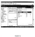
- Selecting the “GetList” function 610can result in the screen depicted in FIG. 7 .
- Screen 700presents to the user a list of tables associated with “GetList” function 610 , from which the user can select one or more tables to be used in conjunction with the data model being created.
- the userhas selected the table 710 , or business object, “KNA1:BAPI_CUSTOMER_GETLIST[All Tables]”, meaning that fields contained in all the tables pertaining to a customer will be returned to the user.
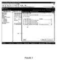
- Screen 800displays a list of fields to the user (not all of which are shown) associated with selected table 710 . From this list the user may select a set of fields to be used in the data model being created. Notice that in screen 800 , the user has selected all of the displayed fields (denoted by the check mark in the box corresponding to the field name).
- Screen 900presents to the user the data store 910 on which the data model is to be based, and presents a field 920 for the user to complete with a name of the data model to be created, and a field 930 which the user may use to describe the data model. Notice the user has completed field 920 with a name for the data model, and field 920 with a description. The user can then create the data model by selecting button 940 .
- Screen 1000confirms the data model has been created, and displays the current fields in the data model.
- the usermay create a field and add this field to the fields of the data model. In one embodiment, this may be done by selecting icon 1010 indicating the user would like to add a field to the existing data model. Selecting icon 1010 results in a screen which enables the user to add a field.
- FIG. 11An embodiment of this screen is depicted in FIG. 11 .
- Screen 1100allows the user to create a field by entering the name of the new field and selecting the data type to be contained in the field. Notice that here the user has named the newly added field “CustomerNo for Subview” and has designated that this field will contain text. The new field can then be created when the user selects the “Save & Define New” button 1110 . The presence of the data model is then indicated in a screen which depicts the various defined components.
- FIG. 12Screen 1200 shows newly defined data model “Kna1 Bapi Customer GetList” 1210 .
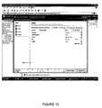
- FIG. 13depicts another example of a screen for displaying defined components.
- data model 1310 named “CUSTOMER_EXPENSES”has been defined from an SAP based data source
- data model 1320 named “SALES”has been defined from an Oracle database.
- a set of viewscan be created based on these data models (STEP 320 ).
- the same graphical application depicted above with respect to FIGS. 4-13may also be used, to assist a user in defining views from various data models.
- FIGS. 14-19depict an embodiment of defining a view using a graphical application.
- a screenmay be presented to the user to assist in creating a view. This screen is depicted in FIG. 14 .
- Screen 1400may be part of a view creation wizard intended to assist the user in creating a view.
- Screen 1400allows the user to select the type of view he wishes to create. In one embodiment, these types comprise a chart, a form, or a report, as described above.
- the usermay also use screen 1400 to designate which data model the view is to be based on, the name of the view being created and certain options available in conjunction with the view. For example, in the screen depicted in FIG. 14 , the user has selected to create a view named “Expenses” of the report type, based on the data model “CUSTOMER_EXPENSES” 1310 .
- the userhas also designated that the view created may be searched according to a criteria.
- the useris then presented with a screen, such as that depicted in FIG. 15 , that presents to the user the fields contained in the data model on which the view is based, and allows the user to select the fields in the data model that the user wishes to include in the view being created.
- a screensuch as that depicted in FIG. 15
- the usermay select these fields by placing a check in the box corresponding to the field. Note that in screen 1500 , the user has selected all the fields except for the “ID” field.
- FIG. 16An embodiment of this screen is shown in FIG. 16 .
- Screen 1600allows the user to select a data field from the data model to use as a search criterion to be used with the view, and designate a label for this criterion.
- the data displayed by the viewmay be altered according to the criterion designated in screen 1600 .
- the userhas designated that the view can be searched or altered based on the field “CUSTOMERNO” and has labeled this field “CUSTOMERNO” as well.
- the usermay then create the view by clicking on the “Create View” button 1610 .
- a screenmay be displayed confirming to the user that the view has been created, as depicted in FIG. 17 .
- Screen 1700indicates that the view “Expenses” which is a report type view based on the data model “CUSTOMER_EXPENSES” has been created.
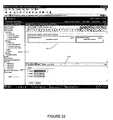
- FIG. 18One embodiment of a screen for presenting the user with a preview of the view, and an editor is depicted in FIG. 18 .
- Screen 1800contains frame 1810 which presents format 1812 of how the created view will appear. This format 1812 may be altered using editor 1816 presented to the user in frame 1820 . More specifically, the user may highlight a portion of format 1812 and the parameters of the highlighted portion appear automatically in editor 1816 . The user may then alter the parameters in editor 1816 to alter format 1812 of the created view. In screen 1800 , the user is in the midst of editing the “name” portion of format 1812 .
- FIG. 19depicts how a created view is displayed in the applications list of components. Screen 1900 depicts “Expenses” view 1910 of type report.
- FIG. 20depicts the appearance of the defined list of components after another view 2010 has been added.
- View 2010is named “Sales” and is a view of type chart.
- subviewsmay also be defined for the view.
- subviews for a viewwhenever a view is displayed subviews of the view may also be formed and displayed.
- the same graphical application depicted above with respect to FIGS. 4-20may also be used to assist a user in defining views from various data models.
- FIGS. 21-27depict the process for defining subviews of a view in more detail.
- a subview named “Subview” of type formhas been defined.
- FIG. 21depicts a screen presenting a preview of the created view along with an editor to allow further definition of the presentation of the view similar to that depicted in FIG. 18 .
- Screen 2100contains frame 2110 which presents format 2112 of how the created view “Subview” will appear. This format 2112 may be altered using editor 2116 presented to the user in frame 2120 . More specifically, a user may choose to define two subviews for the view “Subview”.
- FIG. 22depicts the format 2212 of the view “Subview”, including two subview frames 2213 and 2214 indicating where the two added subviews are to be displayed.
- a usermay edit the appearance of the subview frame, and assign a view to be displayed in that subview frame.
- the userhas clicked on subview frame 2214 “New Subview Frame 2” and the parameters for “New Subview Frame 2” appear in editor frame 2220 . These parameters can then be altered to refine the appearance of the view which will appear in subview frame 2214 .
- Viewscan then be associated with each of subview frames 2213 , 2214 .
- a screenmay be presented to the user to allow a user to select a view to be presented in subview frame 2213 .
- FIG. 23depicts one embodiment for such a screen.
- Screen 2300presents a list of the available views from which the user can select. A user can then select one of these views screen for display in the subframe. Notice in screen 2300 the user has selected the view “Expenses” for display in subframe 2213 .
- the usermay then be presented with a screen allowing the user to map the field to be searched for the criterion in the subview to a field in the parent view.
- the subviewmay display data associated with a criterion mapped from the parent view.
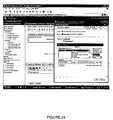
- FIG. 24One embodiment for a screen of this type is depicted in FIG. 24 .
- operators 2410may also be used to further clarify the mapping between fields for a subview and a parent view.
- FIGS. 25 and 26depict the subview selection and field mapping process for subview frame 2214 .
- FIG. 27depicts a screen displaying the defined components after the view “Subview” 2710 has been created.
- FIG. 3once a set of views is created (STEP 320 ) one of these views may be utilized as the master view for the composite view (STEP 330 ). This view may be selected from among the already created views (STEP 330 ) or another view may be created in the set (STEP 320 ) and utilized as the master view (STEP 330 ).
- FIGS. 28-34depict the creation of a new view (STEP 320 ) and utilizing the newly created view as the master view (STEP 330 ).
- a screenmay be presented to the user to assist in creating a view.
- This screenis depicted in FIG. 28 .
- Screen 2800may be part of a view creation wizard intended to assist the user in creating a view.
- Screen 2800allows the user to select the type of view he wishes to create. For example, in the screen depicted in FIG. 28 , the user has selected to create a view named “SAP Customer List” of the report type, based on the data model “Kna1 Bapi Customer Getlist” 2810 . The user has also designated that the view created may be available as a main (or composite) view.
- the useris then presented with the screen, such as that depicted in FIG. 29 , that presents to the user the fields contained in the data model on which the view is based (note that not all fields appear on screen 2900 ), and allows the user to select the fields in the data model that the user wishes to include in the view being created.
- the userhas selected certain fields by placing a check in the box corresponding to the field. Note that in screen 2900 , the user has selected the fields “CITY”, “CUSTOMER”, “NAME”, “REGION” “STREET” and TEL1_NUMBER”.
- a screenmay be displayed confirming to the user that the view has been created, as depicted in FIG. 30 .
- Screen 3000indicates that the view “SAP Customer List” which is a report type view based on the data model “Kna1 Bapi Customer Getlist” has been created.
- Screen 3100contains frame 3110 which presents format 3112 of how the created view will appear. This format 3112 may be altered using the editor 3116 presented to the user in frame 3120 . More specifically, the user may highlight a portion of format 3112 and the parameters of the highlighted portion appear automatically in editor 3116 . The user may then alter the parameters in editor 3116 to alter format 3112 of the created view. In screen 3100 , the user is in the midst of editing the “name” portion of format 3112 . Screen 3100 can also be used to associate subviews with the master view (STEP 340 ), as depicted in FIGS. 32-34 .
- FIG. 32depicts the format 3212 of the view “SAP Customer List” defined including subview frame 3214 indicating where a subview is to be displayed.
- a usermay edit the appearance of a view appearing in subview frame 3214 , and assign a view to be displayed in the subview frame 3214 .
- the userhas clicked on subview frame 3214 “New Subview Frame 1” and the parameters for “New Subview Frame 1” appear in editor 3216 . These parameters can then be altered to refine the appearance of the view which will appear in subview frame 3214 .
- Viewscan then be associated with subview frame, 3214 .
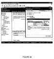
- a screenmay be presented to the user to allow a user to select a view to be presented in subview frame 3214 .
- FIG. 33depicts one embodiment for such a screen.
- Screen 3300presents a list of the available views from which the user can select. A user can then select one of these views screen for display in subframe view 3214 . Notice in screen 3300 the user has selected the view “Subview” for display in subframe 3214 .
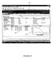
- the usermay then be presented with a screen allowing the user to map the field to be searched for the criterion in the subview to a field in the parent view.
- the subviewmay display data associated with a criterion mapped from the parent view.
- FIG. 34One embodiment for a screen of this type is depicted in FIG. 34 . Notice that in screen 3400 the field “CUSTOMER” in the parent view “SAP Customer List” is mapped to “CustomerNo for Subview” in the subview “Subview” assigned to subview frame 3214 .
- the composite viewcan be interacted with.
- the data displayed by the subviewsmay depend on the interaction with the master view. This interaction may initiate the passing of a criterion from the master view to subviews of the master view based on a mapping between the fields of the master view and each subview, these subviews may display data associated with the criterion and pass the criterion to their subviews based on a mapping between the fields of each subview and its respective subviews.
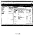
- FIG. 35depicts one embodiment of an initial presentation of a composite view to a user of the composite view.
- the initial presentation of a composite view 3500only data associated with master view 3510 may be displayed. Based on interaction with the master view 3510 , certain data may be displayed in subviews associated with master view 3510 . For example, a user of composite view 3500 may select customer “0000000001” 3520 . Based on the selection of this customer number data may displayed.
- FIG. 36depicts one embodiment of the display of composite view 3500 based on the selection of customer “0000000001” 3620 .
- subview 3630 of master view 3510may display the customer number
- subviews 3640 and 3650 of subview 3630may in turn display sales data associated with customer “0000000001” from different data sources, subview 3640 in report form and subview 3650 in chart form.
- a user interacting with composite view 3500may then desire data on a different customer and select customer “0000000002” in master view 3510 of composite view 3500 .
- FIG. 37depicts one embodiment of the display of composite view 3500 based on the selection of customer “0000000002”.
- subview 3630 of master view 3510may display the customer number; subviews 3640 and 3650 of subview 3630 may in turn display sales data associated with customer “0000000002” from different data sources, subview 3640 in report form and subview 3650 in chart form.
- master view 3510 of composite view 3500a wide variety of associated data from a variety of different data sources may be presented to users in a whole host of different formats.
Landscapes
- Engineering & Computer Science (AREA)
- Theoretical Computer Science (AREA)
- Databases & Information Systems (AREA)
- Physics & Mathematics (AREA)
- Data Mining & Analysis (AREA)
- General Engineering & Computer Science (AREA)
- General Physics & Mathematics (AREA)
- Computational Linguistics (AREA)
- Mathematical Physics (AREA)
- Library & Information Science (AREA)
- User Interface Of Digital Computer (AREA)
Abstract
Description
Claims (20)
Priority Applications (1)
| Application Number | Priority Date | Filing Date | Title |
|---|---|---|---|
| US14/709,209US9760603B2 (en) | 2003-12-23 | 2015-05-11 | Method and system to provide composite view of data from disparate data sources |
Applications Claiming Priority (4)
| Application Number | Priority Date | Filing Date | Title |
|---|---|---|---|
| US53223603P | 2003-12-23 | 2003-12-23 | |
| US53209203P | 2003-12-23 | 2003-12-23 | |
| US11/021,588US9053149B2 (en) | 2003-12-23 | 2004-12-22 | Method and system to provide composite view of components |
| US14/709,209US9760603B2 (en) | 2003-12-23 | 2015-05-11 | Method and system to provide composite view of data from disparate data sources |
Related Parent Applications (1)
| Application Number | Title | Priority Date | Filing Date |
|---|---|---|---|
| US11/021,588ContinuationUS9053149B2 (en) | 2003-12-23 | 2004-12-22 | Method and system to provide composite view of components |
Publications (2)
| Publication Number | Publication Date |
|---|---|
| US20150310064A1 US20150310064A1 (en) | 2015-10-29 |
| US9760603B2true US9760603B2 (en) | 2017-09-12 |
Family
ID=51166020
Family Applications (2)
| Application Number | Title | Priority Date | Filing Date |
|---|---|---|---|
| US11/021,588Active2027-09-27US9053149B2 (en) | 2003-12-23 | 2004-12-22 | Method and system to provide composite view of components |
| US14/709,209Expired - LifetimeUS9760603B2 (en) | 2003-12-23 | 2015-05-11 | Method and system to provide composite view of data from disparate data sources |
Family Applications Before (1)
| Application Number | Title | Priority Date | Filing Date |
|---|---|---|---|
| US11/021,588Active2027-09-27US9053149B2 (en) | 2003-12-23 | 2004-12-22 | Method and system to provide composite view of components |
Country Status (1)
| Country | Link |
|---|---|
| US (2) | US9053149B2 (en) |
Cited By (1)
| Publication number | Priority date | Publication date | Assignee | Title |
|---|---|---|---|---|
| US11275727B2 (en)* | 2019-09-19 | 2022-03-15 | International Business Machines Corporation | Composite views in a master data management system |
Families Citing this family (7)
| Publication number | Priority date | Publication date | Assignee | Title |
|---|---|---|---|---|
| US9053149B2 (en) | 2003-12-23 | 2015-06-09 | Open Text S.A. | Method and system to provide composite view of components |
| US8099674B2 (en)* | 2005-09-09 | 2012-01-17 | Tableau Software Llc | Computer systems and methods for automatically viewing multidimensional databases |
| US9953273B2 (en)* | 2011-06-28 | 2018-04-24 | Salesforce.Com, Inc. | Systems and methods for creating a rich social media profile |
| US9824128B1 (en)* | 2012-08-01 | 2017-11-21 | The United States Of America As Represented By The Administrator Of Nasa | System for performing single query searches of heterogeneous and dispersed databases |
| EP2778925A3 (en)* | 2013-03-15 | 2014-10-08 | Aetherpal Inc. | Dashboard notifications on management console during a remote control session |
| US10459881B2 (en)* | 2015-02-27 | 2019-10-29 | Podium Data, Inc. | Data management platform using metadata repository |
| US10318319B2 (en)* | 2016-08-26 | 2019-06-11 | Sap Se | Two-model user interface system |
Citations (47)
| Publication number | Priority date | Publication date | Assignee | Title |
|---|---|---|---|---|
| US5737591A (en) | 1996-05-23 | 1998-04-07 | Microsoft Corporation | Database view generation system |
| US5761674A (en) | 1991-05-17 | 1998-06-02 | Shimizu Construction Co., Ltd. | Integrated construction project information management system |
| US5799318A (en) | 1993-04-13 | 1998-08-25 | Firstfloor Software | Method and apparatus for collecting and displaying information from diverse computer resources |
| US5907846A (en) | 1996-06-07 | 1999-05-25 | Electronic Data Systems Corporation | Method and system for accessing relational databases using objects |
| US5930474A (en) | 1996-01-31 | 1999-07-27 | Z Land Llc | Internet organizer for accessing geographically and topically based information |
| US6026390A (en) | 1996-05-29 | 2000-02-15 | At&T Corp | Cost-based maintenance of materialized views |
| US6175837B1 (en) | 1998-06-29 | 2001-01-16 | Sun Microsystems, Inc. | Object-relational mapping toll that processes views |
| US6356256B1 (en) | 1999-01-19 | 2002-03-12 | Vina Technologies, Inc. | Graphical user interface for display of statistical data |
| US20020052954A1 (en) | 2000-04-27 | 2002-05-02 | Polizzi Kathleen Riddell | Method and apparatus for implementing a dynamically updated portal page in an enterprise-wide computer system |
| US6421658B1 (en) | 1999-07-30 | 2002-07-16 | International Business Machines Corporation | Efficient implementation of typed view hierarchies for ORDBMS |
| US20020118226A1 (en) | 2001-02-26 | 2002-08-29 | Hough P. J. | Method for flagging and relating information in a computer system |
| US20020133504A1 (en) | 2000-10-27 | 2002-09-19 | Harry Vlahos | Integrating heterogeneous data and tools |
| US6457009B1 (en) | 1998-11-09 | 2002-09-24 | Denison W. Bollay | Method of searching multiples internet resident databases using search fields in a generic form |
| US20020156806A1 (en) | 2000-04-27 | 2002-10-24 | Cox Kenneth Charles | Method and apparatus for data visualization |
| US6484159B1 (en) | 1999-05-20 | 2002-11-19 | At&T Corp. | Method and system for incremental database maintenance |
| US6529900B1 (en) | 1999-01-14 | 2003-03-04 | International Business Machines Corporation | Method and apparatus for data visualization |
| US6529217B1 (en) | 1999-06-15 | 2003-03-04 | Microsoft Corporation | System and method for graphically displaying a set of data fields |
| US20030078943A1 (en) | 2001-10-19 | 2003-04-24 | Mcgeorge Vernon E. | Conduits for multiple data sources |
| US20030088715A1 (en) | 2001-10-19 | 2003-05-08 | Microsoft Corporation | System for keyword based searching over relational databases |
| US20030135491A1 (en) | 2002-01-16 | 2003-07-17 | Pete Rowley | Directory server views |
| US6609123B1 (en) | 1999-09-03 | 2003-08-19 | Cognos Incorporated | Query engine and method for querying data using metadata model |
| US20030189595A1 (en) | 2001-08-10 | 2003-10-09 | Beard Thomas Richard | Summary data visualisation system and method |
| US6647410B1 (en) | 1999-11-05 | 2003-11-11 | Reuters Limited | Method, apparatus and program for delivery and display of information from dynamic and static data sources |
| US6704743B1 (en) | 1999-09-13 | 2004-03-09 | Copernus, Inc. | Selective inheritance of object parameters in object-oriented computer environment |
| US6718336B1 (en) | 2000-09-29 | 2004-04-06 | Battelle Memorial Institute | Data import system for data analysis system |
| US6738077B1 (en) | 2000-07-18 | 2004-05-18 | Apple Computer, Inc. | Dynamic generation and automated distribution of user interface from database model |
| US20040139085A1 (en) | 2002-12-30 | 2004-07-15 | Evren Eryurek | Data visualization within an integrated asset data system for a process plant |
| US20040181543A1 (en) | 2002-12-23 | 2004-09-16 | Canon Kabushiki Kaisha | Method of using recommendations to visually create new views of data across heterogeneous sources |
| US20040193579A1 (en) | 2003-03-31 | 2004-09-30 | International Business Machines Corporation | Dealing with composite data through data model entities |
| US20040201588A1 (en) | 2003-04-14 | 2004-10-14 | Meanor Phillip C. | Computer-implemented system and method for handling linked data views |
| US6826727B1 (en) | 1999-11-24 | 2004-11-30 | Bitstream Inc. | Apparatus, methods, programming for automatically laying out documents |
| US20050021541A1 (en) | 2003-05-09 | 2005-01-27 | Vasudev Rangadass | Data management system providing a data thesaurus for mapping between multiple data schemas or between multiple domains within a data schema |
| US20050050068A1 (en) | 2003-08-29 | 2005-03-03 | Alexander Vaschillo | Mapping architecture for arbitrary data models |
| US20050080802A1 (en) | 2000-04-03 | 2005-04-14 | Jean-Yves Cras | Analytical reporting on top of multidimensional data model |
| US6915294B1 (en) | 2000-08-18 | 2005-07-05 | Firstrain, Inc. | Method and apparatus for searching network resources |
| US6925477B1 (en) | 1998-03-31 | 2005-08-02 | Intellisync Corporation | Transferring records between two databases |
| US20050187794A1 (en) | 1999-04-28 | 2005-08-25 | Alean Kimak | Electronic medical record registry including data replication |
| US20050268244A1 (en) | 2004-05-28 | 2005-12-01 | Peter Vignet | Method and system to provide direct access to subviews |
| US20060020586A1 (en) | 2000-03-03 | 2006-01-26 | Michel Prompt | System and method for providing access to databases via directories and other hierarchical structures and interfaces |
| US6995768B2 (en) | 2000-05-10 | 2006-02-07 | Cognos Incorporated | Interactive business data visualization system |
| US20060069693A1 (en) | 2004-09-14 | 2006-03-30 | International Business Machines Corporation | System and method for using demographic organization and segmentation to manage large scale projects |
| US20060136469A1 (en) | 2004-12-17 | 2006-06-22 | International Business Machines Corporation | Creating a logical table from multiple differently formatted physical tables having different access methods |
| US20070239772A1 (en) | 2003-06-26 | 2007-10-11 | International Business Machines Corporation | Method and apparatus for reducing index sizes and increasing performance of non-relational database |
| US7320001B1 (en)* | 1999-01-15 | 2008-01-15 | Hon Hai Precision Industry, Ltd. | Method for visualizing information in a data warehousing environment |
| US7418431B1 (en) | 1999-09-30 | 2008-08-26 | Fair Isaac Corporation | Webstation: configurable web-based workstation for reason driven data analysis |
| US7574423B2 (en) | 2003-03-20 | 2009-08-11 | International Business Machines Corporation | Partial data model exposure through client side caching |
| US20140201190A1 (en) | 2003-12-23 | 2014-07-17 | Hillary Ebenstein | Method and system to provide composite view of components |
- 2004
- 2004-12-22USUS11/021,588patent/US9053149B2/enactiveActive
- 2015
- 2015-05-11USUS14/709,209patent/US9760603B2/ennot_activeExpired - Lifetime
Patent Citations (52)
| Publication number | Priority date | Publication date | Assignee | Title |
|---|---|---|---|---|
| US5761674A (en) | 1991-05-17 | 1998-06-02 | Shimizu Construction Co., Ltd. | Integrated construction project information management system |
| US5799318A (en) | 1993-04-13 | 1998-08-25 | Firstfloor Software | Method and apparatus for collecting and displaying information from diverse computer resources |
| US5930474A (en) | 1996-01-31 | 1999-07-27 | Z Land Llc | Internet organizer for accessing geographically and topically based information |
| US5737591A (en) | 1996-05-23 | 1998-04-07 | Microsoft Corporation | Database view generation system |
| US6026390A (en) | 1996-05-29 | 2000-02-15 | At&T Corp | Cost-based maintenance of materialized views |
| US5907846A (en) | 1996-06-07 | 1999-05-25 | Electronic Data Systems Corporation | Method and system for accessing relational databases using objects |
| US6925477B1 (en) | 1998-03-31 | 2005-08-02 | Intellisync Corporation | Transferring records between two databases |
| US6175837B1 (en) | 1998-06-29 | 2001-01-16 | Sun Microsystems, Inc. | Object-relational mapping toll that processes views |
| US6457009B1 (en) | 1998-11-09 | 2002-09-24 | Denison W. Bollay | Method of searching multiples internet resident databases using search fields in a generic form |
| US6529900B1 (en) | 1999-01-14 | 2003-03-04 | International Business Machines Corporation | Method and apparatus for data visualization |
| US7320001B1 (en)* | 1999-01-15 | 2008-01-15 | Hon Hai Precision Industry, Ltd. | Method for visualizing information in a data warehousing environment |
| US6356256B1 (en) | 1999-01-19 | 2002-03-12 | Vina Technologies, Inc. | Graphical user interface for display of statistical data |
| US20050187794A1 (en) | 1999-04-28 | 2005-08-25 | Alean Kimak | Electronic medical record registry including data replication |
| US6484159B1 (en) | 1999-05-20 | 2002-11-19 | At&T Corp. | Method and system for incremental database maintenance |
| US6529217B1 (en) | 1999-06-15 | 2003-03-04 | Microsoft Corporation | System and method for graphically displaying a set of data fields |
| US6421658B1 (en) | 1999-07-30 | 2002-07-16 | International Business Machines Corporation | Efficient implementation of typed view hierarchies for ORDBMS |
| US6609123B1 (en) | 1999-09-03 | 2003-08-19 | Cognos Incorporated | Query engine and method for querying data using metadata model |
| US6662188B1 (en) | 1999-09-03 | 2003-12-09 | Cognos Incorporated | Metadata model |
| US6704743B1 (en) | 1999-09-13 | 2004-03-09 | Copernus, Inc. | Selective inheritance of object parameters in object-oriented computer environment |
| US7418431B1 (en) | 1999-09-30 | 2008-08-26 | Fair Isaac Corporation | Webstation: configurable web-based workstation for reason driven data analysis |
| US6647410B1 (en) | 1999-11-05 | 2003-11-11 | Reuters Limited | Method, apparatus and program for delivery and display of information from dynamic and static data sources |
| US6826727B1 (en) | 1999-11-24 | 2004-11-30 | Bitstream Inc. | Apparatus, methods, programming for automatically laying out documents |
| US20060020586A1 (en) | 2000-03-03 | 2006-01-26 | Michel Prompt | System and method for providing access to databases via directories and other hierarchical structures and interfaces |
| US20050080802A1 (en) | 2000-04-03 | 2005-04-14 | Jean-Yves Cras | Analytical reporting on top of multidimensional data model |
| US20020156806A1 (en) | 2000-04-27 | 2002-10-24 | Cox Kenneth Charles | Method and apparatus for data visualization |
| US20020052954A1 (en) | 2000-04-27 | 2002-05-02 | Polizzi Kathleen Riddell | Method and apparatus for implementing a dynamically updated portal page in an enterprise-wide computer system |
| US8386920B2 (en) | 2000-04-27 | 2013-02-26 | Alcatel Lucent | Method and apparatus for data visualization |
| US6995768B2 (en) | 2000-05-10 | 2006-02-07 | Cognos Incorporated | Interactive business data visualization system |
| US6738077B1 (en) | 2000-07-18 | 2004-05-18 | Apple Computer, Inc. | Dynamic generation and automated distribution of user interface from database model |
| US6915294B1 (en) | 2000-08-18 | 2005-07-05 | Firstrain, Inc. | Method and apparatus for searching network resources |
| US6718336B1 (en) | 2000-09-29 | 2004-04-06 | Battelle Memorial Institute | Data import system for data analysis system |
| US20020133504A1 (en) | 2000-10-27 | 2002-09-19 | Harry Vlahos | Integrating heterogeneous data and tools |
| US20020118226A1 (en) | 2001-02-26 | 2002-08-29 | Hough P. J. | Method for flagging and relating information in a computer system |
| US20030189595A1 (en) | 2001-08-10 | 2003-10-09 | Beard Thomas Richard | Summary data visualisation system and method |
| US20030088715A1 (en) | 2001-10-19 | 2003-05-08 | Microsoft Corporation | System for keyword based searching over relational databases |
| US20030078943A1 (en) | 2001-10-19 | 2003-04-24 | Mcgeorge Vernon E. | Conduits for multiple data sources |
| US20030135491A1 (en) | 2002-01-16 | 2003-07-17 | Pete Rowley | Directory server views |
| US20040181543A1 (en) | 2002-12-23 | 2004-09-16 | Canon Kabushiki Kaisha | Method of using recommendations to visually create new views of data across heterogeneous sources |
| US20040139085A1 (en) | 2002-12-30 | 2004-07-15 | Evren Eryurek | Data visualization within an integrated asset data system for a process plant |
| US7574423B2 (en) | 2003-03-20 | 2009-08-11 | International Business Machines Corporation | Partial data model exposure through client side caching |
| US7054877B2 (en) | 2003-03-31 | 2006-05-30 | International Business Machines Corporation | Dealing with composite data through data model entities |
| US20040193579A1 (en) | 2003-03-31 | 2004-09-30 | International Business Machines Corporation | Dealing with composite data through data model entities |
| US20040201588A1 (en) | 2003-04-14 | 2004-10-14 | Meanor Phillip C. | Computer-implemented system and method for handling linked data views |
| US20050021541A1 (en) | 2003-05-09 | 2005-01-27 | Vasudev Rangadass | Data management system providing a data thesaurus for mapping between multiple data schemas or between multiple domains within a data schema |
| US20070239772A1 (en) | 2003-06-26 | 2007-10-11 | International Business Machines Corporation | Method and apparatus for reducing index sizes and increasing performance of non-relational database |
| US7289990B2 (en) | 2003-06-26 | 2007-10-30 | International Business Machines Corporation | Method and apparatus for reducing index sizes and increasing performance of non-relational databases |
| US20050050068A1 (en) | 2003-08-29 | 2005-03-03 | Alexander Vaschillo | Mapping architecture for arbitrary data models |
| US20140201190A1 (en) | 2003-12-23 | 2014-07-17 | Hillary Ebenstein | Method and system to provide composite view of components |
| US9053149B2 (en) | 2003-12-23 | 2015-06-09 | Open Text S.A. | Method and system to provide composite view of components |
| US20050268244A1 (en) | 2004-05-28 | 2005-12-01 | Peter Vignet | Method and system to provide direct access to subviews |
| US20060069693A1 (en) | 2004-09-14 | 2006-03-30 | International Business Machines Corporation | System and method for using demographic organization and segmentation to manage large scale projects |
| US20060136469A1 (en) | 2004-12-17 | 2006-06-22 | International Business Machines Corporation | Creating a logical table from multiple differently formatted physical tables having different access methods |
Non-Patent Citations (19)
| Title |
|---|
| Notice of Allowance issued for U.S. Appl. No. 11/021,588, mailed Feb. 6, 2015, 11 pages. |
| Office Action issued for U.S. Appl. No. 11/020,959, mailed Jan. 22, 2008, 16 pages. |
| Office Action issued for U.S. Appl. No. 11/020,959, mailed Jan. 22, 2009, 15 pages. |
| Office Action issued for U.S. Appl. No. 11/020,959, mailed Jul. 3, 2008, 15 pages. |
| Office Action issued for U.S. Appl. No. 11/020,959, mailed Mar. 13, 2007, 12 pages. |
| Office Action issued for U.S. Appl. No. 11/021,588, mailed Apr. 1, 2009, 16 pages. |
| Office Action issued for U.S. Appl. No. 11/021,588, mailed Aug. 1, 2013, 15 pages. |
| Office Action issued for U.S. Appl. No. 11/021,588, mailed Dec. 1, 2013, 18 pages. |
| Office Action issued for U.S. Appl. No. 11/021,588, mailed Dec. 11, 2007, 12 pages. |
| Office Action issued for U.S. Appl. No. 11/021,588, mailed Dec. 27, 2006, 10 pages. |
| Office Action issued for U.S. Appl. No. 11/021,588, mailed Jan. 17, 2013, 20 pages. |
| Office Action issued for U.S. Appl. No. 11/021,588, mailed Jul. 15, 2014, 20 pages. |
| Office Action issued for U.S. Appl. No. 11/021,588, mailed Jun. 29, 2007, 11 pages. |
| Office Action issued for U.S. Appl. No. 11/021,588, mailed Mar. 15, 2011, 14 pages. |
| Office Action issued for U.S. Appl. No. 11/021,588, mailed Mar. 30, 2010, 13 pages. |
| Office Action issued for U.S. Appl. No. 11/021,588, mailed Oct. 1, 2010, 13 pages. |
| Office Action issued for U.S. Appl. No. 11/021,588, mailed Oct. 6, 2009, 18 pages. |
| Office Action issued for U.S. Appl. No. 11/947,468, mailed Oct. 27, 2010, 10 pages. |
| Priebe et al., Towards Integrative Enterprise Knowledge Portals, CIKM'03, Nov. 3-8, 2003, New Orleans, LA, pp. 216-223. |
Cited By (2)
| Publication number | Priority date | Publication date | Assignee | Title |
|---|---|---|---|---|
| US11275727B2 (en)* | 2019-09-19 | 2022-03-15 | International Business Machines Corporation | Composite views in a master data management system |
| US11822543B2 (en) | 2019-09-19 | 2023-11-21 | International Business Machines Corporation | Composite views in a master data management system |
Also Published As
| Publication number | Publication date |
|---|---|
| US9053149B2 (en) | 2015-06-09 |
| US20140201190A1 (en) | 2014-07-17 |
| US20150310064A1 (en) | 2015-10-29 |
Similar Documents
| Publication | Publication Date | Title |
|---|---|---|
| US9760603B2 (en) | Method and system to provide composite view of data from disparate data sources | |
| US11106626B2 (en) | Managing changes to one or more files via linked mapping records | |
| US9727836B2 (en) | Systems and methods for generating data visualization dashboards | |
| US7734619B2 (en) | Method of presenting lineage diagrams representing query plans | |
| US8185563B2 (en) | Data-visualization system and method | |
| US6263339B1 (en) | Dynamic object visualization and code generation | |
| US8190992B2 (en) | Grouping and display of logically defined reports | |
| US7334196B2 (en) | User interface display navigation and item selection system | |
| US20090064025A1 (en) | KPI Builder | |
| US20190018832A1 (en) | Database model which provides management of custom fields and methods and apparatus therfor | |
| US20070274154A1 (en) | Apparatus and method for relating graphical representations of data tables | |
| US20060005124A1 (en) | User interface for complex process implementation | |
| US7333991B2 (en) | Digital design and maintenance system and method | |
| US8122007B2 (en) | Method and system for interactively exploring data objects | |
| EP1854000A1 (en) | Integrated system, tools, and methods for designing automated business process applications | |
| US7818328B2 (en) | API for obtaining unambiguous representation of objects in a relational database | |
| CN109002334B (en) | Operation and maintenance platform and data processing method thereof | |
| US6915298B1 (en) | User-defined relationships for diagramming user-defined database relations | |
| EP2137643A1 (en) | Method and system for navigation and visualization of data in relational and/or multidimensional databases | |
| Folmer et al. | Enhancing the usefulness of open governmental data with linked data viewing techniques | |
| US20090171931A1 (en) | Obtaining Information From an Object | |
| US20100011019A1 (en) | Database Business Components Code Generator | |
| CN119226521A (en) | An integrated display and management system for intelligent construction application resources based on knowledge graph | |
| JP2002288186A (en) | Method and system for classification and management of electronic data | |
| CN119783803A (en) | Knowledge graph construction method and system for complex relational business database |
Legal Events
| Date | Code | Title | Description |
|---|---|---|---|
| AS | Assignment | Owner name:VIGNETTE CORPORATION, TEXAS Free format text:ASSIGNMENT OF ASSIGNORS INTEREST;ASSIGNORS:EBENSTEIN, HILLARY;GOODWIN, GILES;PENSTON, GEORGE;AND OTHERS;SIGNING DATES FROM 20050103 TO 20050425;REEL/FRAME:035690/0679 Owner name:VIGNETTE CORPORATION, TEXAS Free format text:MERGER;ASSIGNOR:VIGNETTE SOFTWARE, LLC;REEL/FRAME:035690/0817 Effective date:20100330 Owner name:VIGNETTE PARTNERSHIP, LP, TEXAS Free format text:CONVERSION;ASSIGNOR:VIGNETTE OPERATING, LLC;REEL/FRAME:035749/0188 Effective date:20100624 Owner name:VIGNETTE LLC, TEXAS Free format text:INTELLECTUAL PROPERTY PURCHASE AGREEMENT;ASSIGNOR:VIGNETTE CORPORATION (96%);REEL/FRAME:035749/0082 Effective date:20090717 Owner name:VIGNETTE SOFTWARE LLC (96%), TEXAS Free format text:INTELLECTUAL PROPERTY PURCHASE AGREEMENT;ASSIGNOR:VIGNETTE LLC (96%);REEL/FRAME:035749/0137 Effective date:20090717 Owner name:VIGNETTE OPERATING, LLC, TEXAS Free format text:CONVERSION;ASSIGNOR:VIGNETTE CORPORATION;REEL/FRAME:035749/0180 Effective date:20100624 Owner name:VIGNETTE SOFTWARE LLC, TEXAS Free format text:INTELLECTUAL PROPERTY PURCHASE AGREEMENT;ASSIGNOR:VIGNETTE CORPORATION (4%);REEL/FRAME:035751/0053 Effective date:20090717 | |
| AS | Assignment | Owner name:OPEN TEXT S.A., LUXEMBOURG Free format text:ASSIGNMENT OF ASSIGNORS INTEREST;ASSIGNOR:VIGNETTE PARTNERSHIP, LP;REEL/FRAME:037420/0865 Effective date:20110725 | |
| AS | Assignment | Owner name:OT IP SUB, LLC, DELAWARE Free format text:IP BUSINESS SALE AGREEMENT;ASSIGNOR:OPEN TEXT S.A.;REEL/FRAME:040019/0627 Effective date:20160701 Owner name:OPEN TEXT SA ULC, CANADA Free format text:CERTIFICATE OF AMALGAMATION;ASSIGNOR:IP OT SUB ULC;REEL/FRAME:040019/0578 Effective date:20160708 Owner name:IP OT SUB ULC, CANADA Free format text:CERTIFICATE OF CONTINUANCE;ASSIGNOR:OP IP SUB, LLC;REEL/FRAME:040019/0500 Effective date:20160702 | |
| STCF | Information on status: patent grant | Free format text:PATENTED CASE | |
| MAFP | Maintenance fee payment | Free format text:PAYMENT OF MAINTENANCE FEE, 4TH YEAR, LARGE ENTITY (ORIGINAL EVENT CODE: M1551); ENTITY STATUS OF PATENT OWNER: LARGE ENTITY Year of fee payment:4 | |
| FEPP | Fee payment procedure | Free format text:MAINTENANCE FEE REMINDER MAILED (ORIGINAL EVENT CODE: REM.); ENTITY STATUS OF PATENT OWNER: LARGE ENTITY |