US9757912B2 - One-piece multi-lens optical member with ultraviolet inhibitor and method of manufacture - Google Patents
One-piece multi-lens optical member with ultraviolet inhibitor and method of manufactureDownload PDFInfo
- Publication number
- US9757912B2 US9757912B2US14/470,786US201414470786AUS9757912B2US 9757912 B2US9757912 B2US 9757912B2US 201414470786 AUS201414470786 AUS 201414470786AUS 9757912 B2US9757912 B2US 9757912B2
- Authority
- US
- United States
- Prior art keywords
- lens
- optical member
- led light
- lenses
- infused
- Prior art date
- Legal status (The legal status is an assumption and is not a legal conclusion. Google has not performed a legal analysis and makes no representation as to the accuracy of the status listed.)
- Active, expires
Links
- 230000003287optical effectEffects0.000titleclaimsabstractdescription97
- 239000003112inhibitorSubstances0.000titleclaimsabstractdescription34
- 238000004519manufacturing processMethods0.000titleclaimsabstractdescription12
- 238000000034methodMethods0.000titleclaimsdescription16
- 230000007774longtermEffects0.000claimsabstractdescription11
- 239000000463materialSubstances0.000claimsdescription43
- 229920000515polycarbonatePolymers0.000claimsdescription33
- 239000004417polycarbonateSubstances0.000claimsdescription33
- NIXOWILDQLNWCW-UHFFFAOYSA-Nacrylic acid groupChemical groupC(C=C)(=O)ONIXOWILDQLNWCW-UHFFFAOYSA-N0.000claimsdescription12
- 229920000089Cyclic olefin copolymerPolymers0.000claimsdescription4
- 239000004713Cyclic olefin copolymerSubstances0.000claimsdescription4
- 239000007788liquidSubstances0.000claimsdescription3
- 239000002904solventSubstances0.000claimsdescription3
- 229920002050silicone resinPolymers0.000claimsdescription2
- 230000002093peripheral effectEffects0.000abstractdescription4
- 238000001746injection mouldingMethods0.000description14
- 230000015556catabolic processEffects0.000description10
- 238000006731degradation reactionMethods0.000description10
- 229920003229poly(methyl methacrylate)Polymers0.000description6
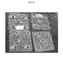
- 238000004383yellowingMethods0.000description6
- MENAYYMPBRSAAE-AWEZNQCLSA-N3-[[5-[[(2s)-1-carboxy-3-oxopropan-2-yl]carbamoyl]pyridin-2-yl]methylsulfamoyl]benzoic acidChemical compoundN1=CC(C(=O)N[C@@H](CC(=O)O)C=O)=CC=C1CNS(=O)(=O)C1=CC=CC(C(O)=O)=C1MENAYYMPBRSAAE-AWEZNQCLSA-N0.000description4
- 239000000654additiveSubstances0.000description4
- 239000004926polymethyl methacrylateSubstances0.000description4
- 238000001802infusionMethods0.000description3
- 229920006397acrylic thermoplasticPolymers0.000description2
- 230000015572biosynthetic processEffects0.000description2
- 238000013329compoundingMethods0.000description2
- 238000005516engineering processMethods0.000description2
- 238000002347injectionMethods0.000description2
- 239000007924injectionSubstances0.000description2
- 230000002035prolonged effectEffects0.000description2
- ISXSCDLOGDJUNJ-UHFFFAOYSA-Ntert-butyl prop-2-enoateChemical compoundCC(C)(C)OC(=O)C=CISXSCDLOGDJUNJ-UHFFFAOYSA-N0.000description2
- 229920000297RayonPolymers0.000description1
- 229920006243acrylic copolymerPolymers0.000description1
- 230000009286beneficial effectEffects0.000description1
- 239000012876carrier materialSubstances0.000description1
- 238000000576coating methodMethods0.000description1
- 230000000052comparative effectEffects0.000description1
- 230000001010compromised effectEffects0.000description1
- 230000007423decreaseEffects0.000description1
- 238000009826distributionMethods0.000description1
- 239000000975dyeSubstances0.000description1
- 239000011521glassSubstances0.000description1
- 238000005286illuminationMethods0.000description1
- 238000007654immersionMethods0.000description1
- 239000002964rayonSubstances0.000description1
- 238000007493shaping processMethods0.000description1
- 238000005507sprayingMethods0.000description1
Images


Classifications
- B—PERFORMING OPERATIONS; TRANSPORTING
- B29—WORKING OF PLASTICS; WORKING OF SUBSTANCES IN A PLASTIC STATE IN GENERAL
- B29D—PRODUCING PARTICULAR ARTICLES FROM PLASTICS OR FROM SUBSTANCES IN A PLASTIC STATE
- B29D11/00—Producing optical elements, e.g. lenses or prisms
- B29D11/0073—Optical laminates
- B—PERFORMING OPERATIONS; TRANSPORTING
- B29—WORKING OF PLASTICS; WORKING OF SUBSTANCES IN A PLASTIC STATE IN GENERAL
- B29C—SHAPING OR JOINING OF PLASTICS; SHAPING OF MATERIAL IN A PLASTIC STATE, NOT OTHERWISE PROVIDED FOR; AFTER-TREATMENT OF THE SHAPED PRODUCTS, e.g. REPAIRING
- B29C45/00—Injection moulding, i.e. forcing the required volume of moulding material through a nozzle into a closed mould; Apparatus therefor
- B29C45/0001—Injection moulding, i.e. forcing the required volume of moulding material through a nozzle into a closed mould; Apparatus therefor characterised by the choice of material
- B—PERFORMING OPERATIONS; TRANSPORTING
- B29—WORKING OF PLASTICS; WORKING OF SUBSTANCES IN A PLASTIC STATE IN GENERAL
- B29C—SHAPING OR JOINING OF PLASTICS; SHAPING OF MATERIAL IN A PLASTIC STATE, NOT OTHERWISE PROVIDED FOR; AFTER-TREATMENT OF THE SHAPED PRODUCTS, e.g. REPAIRING
- B29C45/00—Injection moulding, i.e. forcing the required volume of moulding material through a nozzle into a closed mould; Apparatus therefor
- B29C45/0053—Injection moulding, i.e. forcing the required volume of moulding material through a nozzle into a closed mould; Apparatus therefor combined with a final operation, e.g. shaping
- F—MECHANICAL ENGINEERING; LIGHTING; HEATING; WEAPONS; BLASTING
- F21—LIGHTING
- F21V—FUNCTIONAL FEATURES OR DETAILS OF LIGHTING DEVICES OR SYSTEMS THEREOF; STRUCTURAL COMBINATIONS OF LIGHTING DEVICES WITH OTHER ARTICLES, NOT OTHERWISE PROVIDED FOR
- F21V5/00—Refractors for light sources
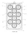
- F21V5/007—Array of lenses or refractors for a cluster of light sources, e.g. for arrangement of multiple light sources in one plane
- B—PERFORMING OPERATIONS; TRANSPORTING
- B29—WORKING OF PLASTICS; WORKING OF SUBSTANCES IN A PLASTIC STATE IN GENERAL
- B29C—SHAPING OR JOINING OF PLASTICS; SHAPING OF MATERIAL IN A PLASTIC STATE, NOT OTHERWISE PROVIDED FOR; AFTER-TREATMENT OF THE SHAPED PRODUCTS, e.g. REPAIRING
- B29C45/00—Injection moulding, i.e. forcing the required volume of moulding material through a nozzle into a closed mould; Apparatus therefor
- B29C45/16—Making multilayered or multicoloured articles
- B—PERFORMING OPERATIONS; TRANSPORTING
- B29—WORKING OF PLASTICS; WORKING OF SUBSTANCES IN A PLASTIC STATE IN GENERAL
- B29K—INDEXING SCHEME ASSOCIATED WITH SUBCLASSES B29B, B29C OR B29D, RELATING TO MOULDING MATERIALS OR TO MATERIALS FOR MOULDS, REINFORCEMENTS, FILLERS OR PREFORMED PARTS, e.g. INSERTS
- B29K2069/00—Use of PC, i.e. polycarbonates or derivatives thereof, as moulding material
- F—MECHANICAL ENGINEERING; LIGHTING; HEATING; WEAPONS; BLASTING
- F21—LIGHTING
- F21Y—INDEXING SCHEME ASSOCIATED WITH SUBCLASSES F21K, F21L, F21S and F21V, RELATING TO THE FORM OR THE KIND OF THE LIGHT SOURCES OR OF THE COLOUR OF THE LIGHT EMITTED
- F21Y2105/00—Planar light sources
- F21Y2105/10—Planar light sources comprising a two-dimensional array of point-like light-generating elements
- F—MECHANICAL ENGINEERING; LIGHTING; HEATING; WEAPONS; BLASTING
- F21—LIGHTING
- F21Y—INDEXING SCHEME ASSOCIATED WITH SUBCLASSES F21K, F21L, F21S and F21V, RELATING TO THE FORM OR THE KIND OF THE LIGHT SOURCES OR OF THE COLOUR OF THE LIGHT EMITTED
- F21Y2115/00—Light-generating elements of semiconductor light sources
- F21Y2115/10—Light-emitting diodes [LED]
Definitions
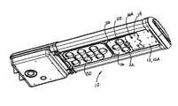
- the inventionrelates generally to the field of LED (light emitting diode) light fixtures and, more particularly, to optical members for such fixtures with LED light sources, and, still more particularly, to polymeric optical members infused with an ultraviolet inhibitor for use in LED light fixtures.
- LEDlight emitting diode
- LED light fixtureswhich are low in cost as well as highly durable to prolonged UV exposure and resistant to yellowing, and which contribute to the overall economy and efficiency of LED light fixtures.
- At least two of the lens layersare of the different polymeric materials.
- one of the lens layersis an acrylic and at least one other lens layer is polycarbonate.
- the lens layer of polycarbonate materialis the innermost layer and is infused with a UV inhibitor. Use of a UV inhibitor infused polycarbonate allows excellent precision in the intended light-directing functions of the lens portions of the unitary optic member, even while providing time and cost-related manufacturing advantages and significantly decreases the amount of yellowing and degradation from UV exposure.
- each of the lenseshas three layers of polymeric material.
- the layersmay be of the same polymeric material, or may be different.
- Another aspect of this inventionis a one-piece optical member of the type described above as a member of an LED light fixture.
- the term “one-piece”means that the portions of the carrier portion which surround the lenses and overlap the lens flanges are overmolded onto such lens flanges such that the layer-to-layer interface is bonded in the overmolding process; and, for those optical members of this invention for which the lenses have plural layers, the layer-to-layer interfaces are bonded in overmolding as well.
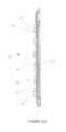
- FIG. 10Bis a side view of the one-piece optical member of the LED lighting fixture of FIG. 1 but infused with the UV inhibitor.
Landscapes
- Engineering & Computer Science (AREA)
- Manufacturing & Machinery (AREA)
- Mechanical Engineering (AREA)
- General Engineering & Computer Science (AREA)
- Health & Medical Sciences (AREA)
- Ophthalmology & Optometry (AREA)
- Led Device Packages (AREA)
- Physics & Mathematics (AREA)
- Spectroscopy & Molecular Physics (AREA)
Abstract
Description
Claims (23)
Priority Applications (1)
| Application Number | Priority Date | Filing Date | Title |
|---|---|---|---|
| US14/470,786US9757912B2 (en) | 2014-08-27 | 2014-08-27 | One-piece multi-lens optical member with ultraviolet inhibitor and method of manufacture |
Applications Claiming Priority (1)
| Application Number | Priority Date | Filing Date | Title |
|---|---|---|---|
| US14/470,786US9757912B2 (en) | 2014-08-27 | 2014-08-27 | One-piece multi-lens optical member with ultraviolet inhibitor and method of manufacture |
Publications (2)
| Publication Number | Publication Date |
|---|---|
| US20160061416A1 US20160061416A1 (en) | 2016-03-03 |
| US9757912B2true US9757912B2 (en) | 2017-09-12 |
Family
ID=55402024
Family Applications (1)
| Application Number | Title | Priority Date | Filing Date |
|---|---|---|---|
| US14/470,786Active2035-03-14US9757912B2 (en) | 2014-08-27 | 2014-08-27 | One-piece multi-lens optical member with ultraviolet inhibitor and method of manufacture |
Country Status (1)
| Country | Link |
|---|---|
| US (1) | US9757912B2 (en) |
Cited By (2)
| Publication number | Priority date | Publication date | Assignee | Title |
|---|---|---|---|---|
| US10468566B2 (en)* | 2017-04-10 | 2019-11-05 | Ideal Industries Lighting Llc | Hybrid lens for controlled light distribution |
| US20220231207A1 (en)* | 2017-04-10 | 2022-07-21 | Ideal Industries Lighting Llc | Hybrid lens for controlled light distribution |
Families Citing this family (1)
| Publication number | Priority date | Publication date | Assignee | Title |
|---|---|---|---|---|
| US20160161642A1 (en)* | 2014-12-03 | 2016-06-09 | Ford Global Technologies, Llc | Hard-coat infused polycarbonate headlamp lens and related method |
Citations (80)
| Publication number | Priority date | Publication date | Assignee | Title |
|---|---|---|---|---|
| US1004585A (en) | 1910-08-15 | 1911-10-03 | Multicolor Sign Co | Illuminated sign. |
| US1024695A (en) | 1911-03-24 | 1912-04-30 | Hugh Mulholland | Illuminated sign. |
| US2212876A (en) | 1938-11-05 | 1940-08-27 | Albert L Chauvet | Nonglare headlight |
| US2254961A (en) | 1937-08-21 | 1941-09-02 | George M Cressaty | Unitary lens system |
| US2544413A (en) | 1942-09-05 | 1951-03-06 | Optische Ind De Oude Deift Nv | Optical lens system comprising one or more aspherical refracting surfaces |
| US4186995A (en) | 1978-03-30 | 1980-02-05 | Amp Incorporated | Light device, lens, and fiber optic package |
| US4474437A (en) | 1982-04-12 | 1984-10-02 | Gorenstein Marc V | Teaching aid for simulating gravitational bending of light |
| US4537474A (en) | 1980-07-30 | 1985-08-27 | Optik Innovation Ab Oiab | Optical system for projection |
| US4561736A (en) | 1982-08-07 | 1985-12-31 | Carl-Zeiss-Stiftung | Eyeglass lenses for persons suffering from severe ametropia |
| US4738516A (en) | 1984-01-18 | 1988-04-19 | U.S. Philips Corp. | Optical element having an aspheric surface |
| US5302778A (en) | 1992-08-28 | 1994-04-12 | Eastman Kodak Company | Semiconductor insulation for optical devices |
| US5494615A (en) | 1994-09-28 | 1996-02-27 | Wang Lee; Min-Young | Method and apparatus for manufacturing eyeglasses by forming integrally a frame unit on a lens unit |
| US6033087A (en) | 1996-12-26 | 2000-03-07 | Patlite Corporation | LED illuminating device for providing a uniform light spot |
| US6123889A (en) | 1997-05-26 | 2000-09-26 | Toyoda Gosei Co., Ltd. | Multi-layer molding method |
| US6273596B1 (en) | 1997-09-23 | 2001-08-14 | Teledyne Lighting And Display Products, Inc. | Illuminating lens designed by extrinsic differential geometry |
| US6356395B1 (en) | 1998-09-14 | 2002-03-12 | Fujitsu Limited | Light intensity distribution converting device and optical data storage apparatus |
| US20020034081A1 (en)* | 2000-09-18 | 2002-03-21 | Koito Manufacturing Co., Ltd. | Vehicle lamp |
| US6395201B1 (en) | 2000-02-03 | 2002-05-28 | Visteon Global Technologies, Inc. | Method and manufacturing an automotive reflector |
| US6499870B1 (en) | 1998-11-06 | 2002-12-31 | Reitter & Schefenacker Gmbh & Co. Kg | Tail light for a motor vehicle |
| US6502956B1 (en) | 1999-03-25 | 2003-01-07 | Leotek Electronics Corporation | Light emitting diode lamp with individual LED lenses |
| US6547423B2 (en) | 2000-12-22 | 2003-04-15 | Koninklijke Phillips Electronics N.V. | LED collimation optics with improved performance and reduced size |
| US6598998B2 (en) | 2001-05-04 | 2003-07-29 | Lumileds Lighting, U.S., Llc | Side emitting light emitting device |
| US6616299B2 (en) | 2001-02-02 | 2003-09-09 | Gelcore Llc | Single optical element LED signal |
| US20030169504A1 (en) | 2002-03-11 | 2003-09-11 | Eastman Kodak Company | Bulk complex polymer lens light diffuser |
| US20030235050A1 (en) | 2002-06-24 | 2003-12-25 | West Robert S. | Side emitting led and lens |
| US20040246606A1 (en) | 2002-10-11 | 2004-12-09 | Pablo Benitez | Compact folded-optics illumination lens |
| US6837605B2 (en) | 2001-11-28 | 2005-01-04 | Osram Opto Semiconductors Gmbh | Led illumination system |
| US20050073840A1 (en) | 2003-10-01 | 2005-04-07 | Chou Der Jeou | Methods and apparatus for an LED light engine |
| US20050086032A1 (en) | 2003-07-28 | 2005-04-21 | Light Prescriptions Innovators, Llc | Three-dimensional simultaneous multiple-surface method and free-form illumination-optics designed therefrom |
| US20050231812A1 (en) | 2004-04-16 | 2005-10-20 | Hon Hai Precision Industry Co., Ltd. | Hybrid lens and method for making same |
| US20060034082A1 (en) | 2004-08-12 | 2006-02-16 | Samsung Electro-Mechanics Co., Ltd. | Multi-lens light emitting diode |
| US20060232881A1 (en) | 2005-04-18 | 2006-10-19 | Hitachi Global Storage Technologies Netherlands B.V. | Magnetic disk drive and fixing clamp |
| US20060252169A1 (en) | 2004-10-07 | 2006-11-09 | Takeshi Ashida | Transparent member, optical device using transparent member and method of manufacturing optical device |
| US7153002B2 (en) | 2004-10-15 | 2006-12-26 | Samsung Electro-Mechanics Co., Ltd. | Lens for LED light sources |
| US20070058369A1 (en) | 2005-01-26 | 2007-03-15 | Parkyn William A | Linear lenses for LEDs |
| US20070070530A1 (en) | 2005-09-27 | 2007-03-29 | Seo Jung H | Light emitting device package and backlight unit using the same |
| US7227703B2 (en) | 2004-07-02 | 2007-06-05 | Hon Hai Precision Industry Co., Ltd. | Aspheric lens and method for making same |
| US7246931B2 (en) | 2004-12-15 | 2007-07-24 | Epistar Corporation | LED light source |
| US7352011B2 (en) | 2004-11-15 | 2008-04-01 | Philips Lumileds Lighting Company, Llc | Wide emitting lens for LED useful for backlighting |
| US20080084693A1 (en) | 2006-10-10 | 2008-04-10 | Yanchers Corporation | Lighting system |
| US20080089210A1 (en) | 2006-04-24 | 2008-04-17 | Sony Corporation | Solid immersion lens, and condenser lens, optical pickup device, and optical recording/reproducing apparatus including the solid immersion lens |
| US7365916B2 (en) | 2004-09-30 | 2008-04-29 | Nikon Corporation | Aspherical lens and optical instrument using the same |
| US7391580B2 (en) | 2005-11-14 | 2008-06-24 | Zeev Maresse | Ultra compact mono-bloc catadioptric imaging lens |
| US20080151550A1 (en) | 2006-12-22 | 2008-06-26 | Hong Kong Applied Science And Technology Research Institute Co. Ltd. | Light-emitting devices and lens therefor |
| US7411742B1 (en) | 2007-02-20 | 2008-08-12 | Sekonix Co., Ltd. | Focusing lens for LED |
| US20080198604A1 (en) | 2007-02-20 | 2008-08-21 | Sekonix Co., Ltd. | Lighting apparatus using filter and condenser for led illumination |
| US20080203415A1 (en) | 2007-02-13 | 2008-08-28 | 3M Innovative Properties Company | Led devices having lenses and methods of making same |
| US20080239722A1 (en) | 2007-04-02 | 2008-10-02 | Ruud Lighting, Inc. | Light-Directing LED Apparatus |
| US20080285136A1 (en) | 2005-08-02 | 2008-11-20 | International Business Machines Corporation | Injection molded microoptics |
| US20080294254A1 (en) | 2005-12-06 | 2008-11-27 | Cumming J Stuart | Intraocular lens |
| WO2008144672A1 (en) | 2007-05-21 | 2008-11-27 | Illumination Management Solutions, Inc. | An improved led device for wide beam generation and method of making the same |
| US20080297020A1 (en) | 2005-09-30 | 2008-12-04 | Osram Opto Semiconductors Gmbh | Illuminiation Arrangement |
| US20080298056A1 (en) | 2007-05-29 | 2008-12-04 | Martin Professional A/S | Light fixture with replaceable optics |
| US20090052192A1 (en) | 2007-08-09 | 2009-02-26 | Sharp Kabushiki Kaisha | Light emitting device and lighting device having the same |
| US7549769B2 (en) | 2005-08-30 | 2009-06-23 | Samsung Electro-Mechanics Co., Ltd. | LED lens for backlight |
| US20090159915A1 (en) | 2007-12-19 | 2009-06-25 | Shaul Branchevsky | Led insert module and multi-layer lens |
| US20100002449A1 (en) | 2008-07-04 | 2010-01-07 | Aurotek Corporation, Ltd. | Method for fabricating micro-lens and mold cavity thereof and light emitting device |
| US20100039810A1 (en) | 2008-08-14 | 2010-02-18 | Cooper Technologies Company | LED Devices for Offset Wide Beam Generation |
| US7722196B2 (en) | 2006-07-14 | 2010-05-25 | Dbm Reflex Enterprises Inc. | Plastic injection of lenses with optical elements and/or retroreflecting prisms that are separated from each other |
| US20100163909A1 (en) | 2007-09-27 | 2010-07-01 | Ming-Hung Chen | Manufacturing method and structure of light-emitting diode with multilayered optical lens |
| US7766509B1 (en) | 2008-06-13 | 2010-08-03 | Lumec Inc. | Orientable lens for an LED fixture |
| US7766530B2 (en) | 2006-10-31 | 2010-08-03 | Samsung Electronics Co., Ltd. | Backlight, a lens for a backlight, and a backlight assembly having the same |
| US20100207140A1 (en) | 2009-02-19 | 2010-08-19 | Koninklijke Philips Electronics N.V. | Compact molded led module |
| US20100271708A1 (en) | 2009-04-28 | 2010-10-28 | Ruud Lighting, Inc. | Lens with controlled light refraction |
| US7874703B2 (en) | 2008-08-28 | 2011-01-25 | Dialight Corporation | Total internal reflection lens with base |
| US7922370B2 (en) | 2009-07-31 | 2011-04-12 | Fu Zhun Precision Industry (Shen Zhen) Co., Ltd. | LED module |
| US20110103051A1 (en)* | 2009-10-30 | 2011-05-05 | Ruud Lighting, Inc. | Led apparatus and method for accurate lens alignment |
| US20110157891A1 (en)* | 2009-11-25 | 2011-06-30 | Davis Matthew A | Systems, Methods, and Devices for Sealing LED Light Sources in a Light Module |
| US20110176301A1 (en) | 2010-01-21 | 2011-07-21 | Dsem Holdings Sdn. Bhd. | Method to produce homogeneous light output by shaping the light conversion material in multichip module |
| WO2011091529A1 (en) | 2010-02-01 | 2011-08-04 | Dbm Reflex Enterprises Inc. | Thick lens molded with embedded layers of the same resin using a two step injection molding process. |
| US20110242823A1 (en)* | 2010-03-30 | 2011-10-06 | Lisa Tracy | Fluorescent bulb cover |
| US20110267822A1 (en) | 2010-04-26 | 2011-11-03 | Xicato, Inc. | Led-based illumination module attachment to a light fixture |
| US20120014115A1 (en) | 2010-01-07 | 2012-01-19 | Seoul Semiconductor Co., Ltd. | Aspherical led lens and light emitting device including the same |
| US20120091487A1 (en) | 2010-10-15 | 2012-04-19 | Advanced Optoelectronic Technology, Inc. | Light emitting diode package and method for manufacturing the same |
| US8215814B2 (en) | 2008-11-21 | 2012-07-10 | Dbm Reflex Enterprises Inc. | Solid state optical illumination apparatus |
| US20120201031A1 (en) | 2011-02-09 | 2012-08-09 | Michael Marley | Headlamp Assembly for Removing Water Based Contamination |
| US20120294011A1 (en) | 2011-05-16 | 2012-11-22 | Shat-R-Shield, Inc. | Method for attaching an optical lens to a printed circuit board with electronic light source |
| US20120319616A1 (en) | 2011-06-14 | 2012-12-20 | Osram Sylvania Inc. | Solid state light fixture with a tunable angular distribution |
| US20120319592A1 (en) | 2011-06-14 | 2012-12-20 | Scott Riesebosch | Methods of monitoring performance of an led lamp |
| US8339716B2 (en) | 2008-12-03 | 2012-12-25 | Philip Premysler | Illumination lenses including light redistributing surfaces |
- 2014
- 2014-08-27USUS14/470,786patent/US9757912B2/enactiveActive
Patent Citations (88)
| Publication number | Priority date | Publication date | Assignee | Title |
|---|---|---|---|---|
| US1004585A (en) | 1910-08-15 | 1911-10-03 | Multicolor Sign Co | Illuminated sign. |
| US1024695A (en) | 1911-03-24 | 1912-04-30 | Hugh Mulholland | Illuminated sign. |
| US2254961A (en) | 1937-08-21 | 1941-09-02 | George M Cressaty | Unitary lens system |
| US2212876A (en) | 1938-11-05 | 1940-08-27 | Albert L Chauvet | Nonglare headlight |
| US2544413A (en) | 1942-09-05 | 1951-03-06 | Optische Ind De Oude Deift Nv | Optical lens system comprising one or more aspherical refracting surfaces |
| US4186995A (en) | 1978-03-30 | 1980-02-05 | Amp Incorporated | Light device, lens, and fiber optic package |
| US4537474A (en) | 1980-07-30 | 1985-08-27 | Optik Innovation Ab Oiab | Optical system for projection |
| US4474437A (en) | 1982-04-12 | 1984-10-02 | Gorenstein Marc V | Teaching aid for simulating gravitational bending of light |
| US4561736A (en) | 1982-08-07 | 1985-12-31 | Carl-Zeiss-Stiftung | Eyeglass lenses for persons suffering from severe ametropia |
| US4738516A (en) | 1984-01-18 | 1988-04-19 | U.S. Philips Corp. | Optical element having an aspheric surface |
| US5302778A (en) | 1992-08-28 | 1994-04-12 | Eastman Kodak Company | Semiconductor insulation for optical devices |
| US5494615A (en) | 1994-09-28 | 1996-02-27 | Wang Lee; Min-Young | Method and apparatus for manufacturing eyeglasses by forming integrally a frame unit on a lens unit |
| US6033087A (en) | 1996-12-26 | 2000-03-07 | Patlite Corporation | LED illuminating device for providing a uniform light spot |
| US6123889A (en) | 1997-05-26 | 2000-09-26 | Toyoda Gosei Co., Ltd. | Multi-layer molding method |
| US6273596B1 (en) | 1997-09-23 | 2001-08-14 | Teledyne Lighting And Display Products, Inc. | Illuminating lens designed by extrinsic differential geometry |
| US6356395B1 (en) | 1998-09-14 | 2002-03-12 | Fujitsu Limited | Light intensity distribution converting device and optical data storage apparatus |
| US20020067549A1 (en) | 1998-09-14 | 2002-06-06 | Fujitsu Limited | Light intensity distribution converting device and optical data storage apparatus |
| US6499870B1 (en) | 1998-11-06 | 2002-12-31 | Reitter & Schefenacker Gmbh & Co. Kg | Tail light for a motor vehicle |
| US6502956B1 (en) | 1999-03-25 | 2003-01-07 | Leotek Electronics Corporation | Light emitting diode lamp with individual LED lenses |
| US6395201B1 (en) | 2000-02-03 | 2002-05-28 | Visteon Global Technologies, Inc. | Method and manufacturing an automotive reflector |
| US20020034081A1 (en)* | 2000-09-18 | 2002-03-21 | Koito Manufacturing Co., Ltd. | Vehicle lamp |
| US6547423B2 (en) | 2000-12-22 | 2003-04-15 | Koninklijke Phillips Electronics N.V. | LED collimation optics with improved performance and reduced size |
| US6616299B2 (en) | 2001-02-02 | 2003-09-09 | Gelcore Llc | Single optical element LED signal |
| US6598998B2 (en) | 2001-05-04 | 2003-07-29 | Lumileds Lighting, U.S., Llc | Side emitting light emitting device |
| US6837605B2 (en) | 2001-11-28 | 2005-01-04 | Osram Opto Semiconductors Gmbh | Led illumination system |
| US20030169504A1 (en) | 2002-03-11 | 2003-09-11 | Eastman Kodak Company | Bulk complex polymer lens light diffuser |
| US20030235050A1 (en) | 2002-06-24 | 2003-12-25 | West Robert S. | Side emitting led and lens |
| US6679621B2 (en) | 2002-06-24 | 2004-01-20 | Lumileds Lighting U.S., Llc | Side emitting LED and lens |
| US7181378B2 (en) | 2002-10-11 | 2007-02-20 | Light Prescriptions Innovators, Llc | Compact folded-optics illumination lens |
| US20040246606A1 (en) | 2002-10-11 | 2004-12-09 | Pablo Benitez | Compact folded-optics illumination lens |
| US6896381B2 (en) | 2002-10-11 | 2005-05-24 | Light Prescriptions Innovators, Llc | Compact folded-optics illumination lens |
| US20050086032A1 (en) | 2003-07-28 | 2005-04-21 | Light Prescriptions Innovators, Llc | Three-dimensional simultaneous multiple-surface method and free-form illumination-optics designed therefrom |
| US20050073840A1 (en) | 2003-10-01 | 2005-04-07 | Chou Der Jeou | Methods and apparatus for an LED light engine |
| US20050231812A1 (en) | 2004-04-16 | 2005-10-20 | Hon Hai Precision Industry Co., Ltd. | Hybrid lens and method for making same |
| US7227703B2 (en) | 2004-07-02 | 2007-06-05 | Hon Hai Precision Industry Co., Ltd. | Aspheric lens and method for making same |
| US20060034082A1 (en) | 2004-08-12 | 2006-02-16 | Samsung Electro-Mechanics Co., Ltd. | Multi-lens light emitting diode |
| US7153000B2 (en) | 2004-08-12 | 2006-12-26 | Samsung Electro-Mechanics Co., Ltd. | Multi-lens light emitting diode |
| US7365916B2 (en) | 2004-09-30 | 2008-04-29 | Nikon Corporation | Aspherical lens and optical instrument using the same |
| US20060252169A1 (en) | 2004-10-07 | 2006-11-09 | Takeshi Ashida | Transparent member, optical device using transparent member and method of manufacturing optical device |
| US7153002B2 (en) | 2004-10-15 | 2006-12-26 | Samsung Electro-Mechanics Co., Ltd. | Lens for LED light sources |
| US7352011B2 (en) | 2004-11-15 | 2008-04-01 | Philips Lumileds Lighting Company, Llc | Wide emitting lens for LED useful for backlighting |
| US7246931B2 (en) | 2004-12-15 | 2007-07-24 | Epistar Corporation | LED light source |
| US20070058369A1 (en) | 2005-01-26 | 2007-03-15 | Parkyn William A | Linear lenses for LEDs |
| US20060232881A1 (en) | 2005-04-18 | 2006-10-19 | Hitachi Global Storage Technologies Netherlands B.V. | Magnetic disk drive and fixing clamp |
| US20080285136A1 (en) | 2005-08-02 | 2008-11-20 | International Business Machines Corporation | Injection molded microoptics |
| US7549769B2 (en) | 2005-08-30 | 2009-06-23 | Samsung Electro-Mechanics Co., Ltd. | LED lens for backlight |
| US20070070530A1 (en) | 2005-09-27 | 2007-03-29 | Seo Jung H | Light emitting device package and backlight unit using the same |
| US20080297020A1 (en) | 2005-09-30 | 2008-12-04 | Osram Opto Semiconductors Gmbh | Illuminiation Arrangement |
| US7391580B2 (en) | 2005-11-14 | 2008-06-24 | Zeev Maresse | Ultra compact mono-bloc catadioptric imaging lens |
| US20080294254A1 (en) | 2005-12-06 | 2008-11-27 | Cumming J Stuart | Intraocular lens |
| US20080089210A1 (en) | 2006-04-24 | 2008-04-17 | Sony Corporation | Solid immersion lens, and condenser lens, optical pickup device, and optical recording/reproducing apparatus including the solid immersion lens |
| US7722196B2 (en) | 2006-07-14 | 2010-05-25 | Dbm Reflex Enterprises Inc. | Plastic injection of lenses with optical elements and/or retroreflecting prisms that are separated from each other |
| US20080084693A1 (en) | 2006-10-10 | 2008-04-10 | Yanchers Corporation | Lighting system |
| US7766530B2 (en) | 2006-10-31 | 2010-08-03 | Samsung Electronics Co., Ltd. | Backlight, a lens for a backlight, and a backlight assembly having the same |
| US20080151550A1 (en) | 2006-12-22 | 2008-06-26 | Hong Kong Applied Science And Technology Research Institute Co. Ltd. | Light-emitting devices and lens therefor |
| US20080203415A1 (en) | 2007-02-13 | 2008-08-28 | 3M Innovative Properties Company | Led devices having lenses and methods of making same |
| US7411742B1 (en) | 2007-02-20 | 2008-08-12 | Sekonix Co., Ltd. | Focusing lens for LED |
| US20080198604A1 (en) | 2007-02-20 | 2008-08-21 | Sekonix Co., Ltd. | Lighting apparatus using filter and condenser for led illumination |
| US20080239722A1 (en) | 2007-04-02 | 2008-10-02 | Ruud Lighting, Inc. | Light-Directing LED Apparatus |
| WO2008144672A1 (en) | 2007-05-21 | 2008-11-27 | Illumination Management Solutions, Inc. | An improved led device for wide beam generation and method of making the same |
| US20100238669A1 (en) | 2007-05-21 | 2010-09-23 | Illumination Management Solutions, Inc. | LED Device for Wide Beam Generation and Method of Making the Same |
| US20080298056A1 (en) | 2007-05-29 | 2008-12-04 | Martin Professional A/S | Light fixture with replaceable optics |
| US20090052192A1 (en) | 2007-08-09 | 2009-02-26 | Sharp Kabushiki Kaisha | Light emitting device and lighting device having the same |
| US20100163909A1 (en) | 2007-09-27 | 2010-07-01 | Ming-Hung Chen | Manufacturing method and structure of light-emitting diode with multilayered optical lens |
| US20090159915A1 (en) | 2007-12-19 | 2009-06-25 | Shaul Branchevsky | Led insert module and multi-layer lens |
| US7766509B1 (en) | 2008-06-13 | 2010-08-03 | Lumec Inc. | Orientable lens for an LED fixture |
| US20100002449A1 (en) | 2008-07-04 | 2010-01-07 | Aurotek Corporation, Ltd. | Method for fabricating micro-lens and mold cavity thereof and light emitting device |
| US20100039810A1 (en) | 2008-08-14 | 2010-02-18 | Cooper Technologies Company | LED Devices for Offset Wide Beam Generation |
| US7874703B2 (en) | 2008-08-28 | 2011-01-25 | Dialight Corporation | Total internal reflection lens with base |
| US8215814B2 (en) | 2008-11-21 | 2012-07-10 | Dbm Reflex Enterprises Inc. | Solid state optical illumination apparatus |
| US8339716B2 (en) | 2008-12-03 | 2012-12-25 | Philip Premysler | Illumination lenses including light redistributing surfaces |
| WO2010095068A2 (en) | 2009-02-19 | 2010-08-26 | Philips Lumileds Lighting Company, Llc | Compact molded led module |
| US20100207140A1 (en) | 2009-02-19 | 2010-08-19 | Koninklijke Philips Electronics N.V. | Compact molded led module |
| US20100271708A1 (en) | 2009-04-28 | 2010-10-28 | Ruud Lighting, Inc. | Lens with controlled light refraction |
| US7922370B2 (en) | 2009-07-31 | 2011-04-12 | Fu Zhun Precision Industry (Shen Zhen) Co., Ltd. | LED module |
| US20110103051A1 (en)* | 2009-10-30 | 2011-05-05 | Ruud Lighting, Inc. | Led apparatus and method for accurate lens alignment |
| US20110157891A1 (en)* | 2009-11-25 | 2011-06-30 | Davis Matthew A | Systems, Methods, and Devices for Sealing LED Light Sources in a Light Module |
| US20120014115A1 (en) | 2010-01-07 | 2012-01-19 | Seoul Semiconductor Co., Ltd. | Aspherical led lens and light emitting device including the same |
| US20110176301A1 (en) | 2010-01-21 | 2011-07-21 | Dsem Holdings Sdn. Bhd. | Method to produce homogeneous light output by shaping the light conversion material in multichip module |
| US20120170280A1 (en) | 2010-02-01 | 2012-07-05 | Dbm Reflex Enterprises Inc. | Illumination apparatus using a solid state source and a thick composite molded lens |
| WO2011091529A1 (en) | 2010-02-01 | 2011-08-04 | Dbm Reflex Enterprises Inc. | Thick lens molded with embedded layers of the same resin using a two step injection molding process. |
| US20110242823A1 (en)* | 2010-03-30 | 2011-10-06 | Lisa Tracy | Fluorescent bulb cover |
| US20110267822A1 (en) | 2010-04-26 | 2011-11-03 | Xicato, Inc. | Led-based illumination module attachment to a light fixture |
| US20120091487A1 (en) | 2010-10-15 | 2012-04-19 | Advanced Optoelectronic Technology, Inc. | Light emitting diode package and method for manufacturing the same |
| US20120201031A1 (en) | 2011-02-09 | 2012-08-09 | Michael Marley | Headlamp Assembly for Removing Water Based Contamination |
| US20120294011A1 (en) | 2011-05-16 | 2012-11-22 | Shat-R-Shield, Inc. | Method for attaching an optical lens to a printed circuit board with electronic light source |
| US20120319616A1 (en) | 2011-06-14 | 2012-12-20 | Osram Sylvania Inc. | Solid state light fixture with a tunable angular distribution |
| US20120319592A1 (en) | 2011-06-14 | 2012-12-20 | Scott Riesebosch | Methods of monitoring performance of an led lamp |
Cited By (3)
| Publication number | Priority date | Publication date | Assignee | Title |
|---|---|---|---|---|
| US10468566B2 (en)* | 2017-04-10 | 2019-11-05 | Ideal Industries Lighting Llc | Hybrid lens for controlled light distribution |
| US20220231207A1 (en)* | 2017-04-10 | 2022-07-21 | Ideal Industries Lighting Llc | Hybrid lens for controlled light distribution |
| US12136689B2 (en)* | 2017-04-10 | 2024-11-05 | Cree Lighting Usa Llc | Hybrid lens for controlled light distribution |
Also Published As
| Publication number | Publication date |
|---|---|
| US20160061416A1 (en) | 2016-03-03 |
Similar Documents
| Publication | Publication Date | Title |
|---|---|---|
| US10422503B2 (en) | One-piece multi-lens optical member and method of manufacture | |
| US11112083B2 (en) | Optic member for an LED light fixture | |
| TWI356150B (en) | ||
| US20110063722A1 (en) | Stacked disk-shaped optical lens array, stacked lens module and method of manufacturing the same | |
| US20110063723A1 (en) | Stacked disk-shaped optical lens array, stacked disk-shaped lens module array and method of manufacturing the same | |
| US9757912B2 (en) | One-piece multi-lens optical member with ultraviolet inhibitor and method of manufacture | |
| KR20130126516A (en) | Method of making stamped multi-layer polymer lens | |
| WO2013063014A3 (en) | Vehicular camera and lens assembly and method of manufacturing same | |
| CN104204865A (en) | Lens array, lens arrange manufacturing method and optical element manufacturing method | |
| CN105698126A (en) | Flash shield, flash component and terminal | |
| CN106200212A (en) | Flash lamp device | |
| JP2013101299A (en) | Flash module for camera, and method of manufacturing the same | |
| TW201826001A (en) | Flash module with shielding for use in mobile phones and other devices | |
| CN205909198U (en) | Flash of light lamp shade, flash light subassembly and terminal | |
| JP7436911B2 (en) | light emitting device | |
| US9920901B2 (en) | LED lensing arrangement | |
| CN101528447B (en) | Method of manufacturing an optical element and a resin-sealed light emitting element and article so obtained | |
| KR101939564B1 (en) | Collimation lens module and light source module using the same | |
| KR101425588B1 (en) | Method of manufacturing led | |
| US20150109807A1 (en) | Vehicle lighting device and method for manufacturing the same | |
| US9505185B2 (en) | Lens mold and method for manufacturing lenses utilizing the lens mold | |
| CN210118712U (en) | Optical assembly and lamp | |
| KR101369378B1 (en) | LED which can improve light efficiency | |
| KR20180129162A (en) | Multilayer lens and manufacturing method therof | |
| US20140376235A1 (en) | Lens with different layers and method making the same |
Legal Events
| Date | Code | Title | Description |
|---|---|---|---|
| AS | Assignment | Owner name:CREE, INC., NORTH CAROLINA Free format text:ASSIGNMENT OF ASSIGNORS INTEREST;ASSIGNORS:RALEIGH, CRAIG;WILCOX, KURT;SIGNING DATES FROM 20140818 TO 20140826;REEL/FRAME:033624/0229 | |
| STCF | Information on status: patent grant | Free format text:PATENTED CASE | |
| AS | Assignment | Owner name:IDEAL INDUSTRIES LIGHTING LLC, ILLINOIS Free format text:ASSIGNMENT OF ASSIGNORS INTEREST;ASSIGNOR:CREE, INC.;REEL/FRAME:049880/0524 Effective date:20190513 | |
| MAFP | Maintenance fee payment | Free format text:PAYMENT OF MAINTENANCE FEE, 4TH YEAR, LARGE ENTITY (ORIGINAL EVENT CODE: M1551); ENTITY STATUS OF PATENT OWNER: LARGE ENTITY Year of fee payment:4 | |
| AS | Assignment | Owner name:FGI WORLDWIDE LLC, NEW YORK Free format text:SECURITY INTEREST;ASSIGNOR:IDEAL INDUSTRIES LIGHTING LLC;REEL/FRAME:064897/0413 Effective date:20230908 | |
| MAFP | Maintenance fee payment | Free format text:PAYMENT OF MAINTENANCE FEE, 8TH YEAR, LARGE ENTITY (ORIGINAL EVENT CODE: M1552); ENTITY STATUS OF PATENT OWNER: LARGE ENTITY Year of fee payment:8 |