US9757856B2 - Highly articulated probes with anti-twist link arrangement, methods of formation thereof, and methods of performing medical procedures - Google Patents
Highly articulated probes with anti-twist link arrangement, methods of formation thereof, and methods of performing medical proceduresDownload PDFInfo
- Publication number
- US9757856B2 US9757856B2US14/343,915US201214343915AUS9757856B2US 9757856 B2US9757856 B2US 9757856B2US 201214343915 AUS201214343915 AUS 201214343915AUS 9757856 B2US9757856 B2US 9757856B2
- Authority
- US
- United States
- Prior art keywords
- link
- articulation
- articulating probe
- motion
- longitudinal axis
- Prior art date
- Legal status (The legal status is an assumption and is not a legal conclusion. Google has not performed a legal analysis and makes no representation as to the accuracy of the status listed.)
- Expired - Fee Related
Links
- 239000000523sampleSubstances0.000titleclaimsabstractdescription136
- 238000000034methodMethods0.000titledescription34
- 230000015572biosynthetic processEffects0.000title1
- 230000007246mechanismEffects0.000claimsabstractdescription50
- 230000013011matingEffects0.000claimsdescription16
- 230000003993interactionEffects0.000description10
- 230000000116mitigating effectEffects0.000description10
- 239000000463materialSubstances0.000description7
- 230000008901benefitEffects0.000description6
- 230000006835compressionEffects0.000description5
- 238000007906compressionMethods0.000description5
- 238000007689inspectionMethods0.000description5
- 238000001356surgical procedureMethods0.000description5
- 230000000712assemblyEffects0.000description3
- 238000000429assemblyMethods0.000description3
- 230000001186cumulative effectEffects0.000description3
- 238000004519manufacturing processMethods0.000description3
- 230000008439repair processEffects0.000description3
- 238000012360testing methodMethods0.000description3
- 230000002411adverseEffects0.000description2
- 210000003484anatomyAnatomy0.000description2
- 238000006243chemical reactionMethods0.000description2
- 230000001419dependent effectEffects0.000description2
- 238000010586diagramMethods0.000description2
- 230000000694effectsEffects0.000description2
- 238000011084recoveryMethods0.000description2
- 241000193738Bacillus anthracisSpecies0.000description1
- 230000005355Hall effectEffects0.000description1
- 230000003213activating effectEffects0.000description1
- WYTGDNHDOZPMIW-RCBQFDQVSA-NalstonineNatural productsC1=CC2=C3C=CC=CC3=NC2=C2N1C[C@H]1[C@H](C)OC=C(C(=O)OC)[C@H]1C2WYTGDNHDOZPMIW-RCBQFDQVSA-N0.000description1
- 239000012472biological sampleSubstances0.000description1
- 210000000988bone and boneAnatomy0.000description1
- 230000008859changeEffects0.000description1
- 238000004891communicationMethods0.000description1
- 238000002405diagnostic procedureMethods0.000description1
- 210000003238esophagusAnatomy0.000description1
- 230000005484gravityEffects0.000description1
- 239000002920hazardous wasteSubstances0.000description1
- 230000002452interceptive effectEffects0.000description1
- 238000002595magnetic resonance imagingMethods0.000description1
- 230000003287optical effectEffects0.000description1
- 210000000056organAnatomy0.000description1
- 238000005067remediationMethods0.000description1
- 238000009877renderingMethods0.000description1
- 238000009420retrofittingMethods0.000description1
- 239000007787solidSubstances0.000description1
- 238000002560therapeutic procedureMethods0.000description1
- 230000007704transitionEffects0.000description1
- 230000000007visual effectEffects0.000description1
- 239000011800void materialSubstances0.000description1
Images


Classifications
- B—PERFORMING OPERATIONS; TRANSPORTING
- B25—HAND TOOLS; PORTABLE POWER-DRIVEN TOOLS; MANIPULATORS
- B25J—MANIPULATORS; CHAMBERS PROVIDED WITH MANIPULATION DEVICES
- B25J9/00—Programme-controlled manipulators
- B25J9/06—Programme-controlled manipulators characterised by multi-articulated arms
- B25J9/065—Snake robots
- A—HUMAN NECESSITIES
- A61—MEDICAL OR VETERINARY SCIENCE; HYGIENE
- A61B—DIAGNOSIS; SURGERY; IDENTIFICATION
- A61B1/00—Instruments for performing medical examinations of the interior of cavities or tubes of the body by visual or photographical inspection, e.g. endoscopes; Illuminating arrangements therefor
- A61B1/005—Flexible endoscopes
- A61B1/0051—Flexible endoscopes with controlled bending of insertion part
- A61B1/0055—Constructional details of insertion parts, e.g. vertebral elements
- A61B1/0056—Constructional details of insertion parts, e.g. vertebral elements the insertion parts being asymmetric, e.g. for unilateral bending mechanisms
- A—HUMAN NECESSITIES
- A61—MEDICAL OR VETERINARY SCIENCE; HYGIENE
- A61B—DIAGNOSIS; SURGERY; IDENTIFICATION
- A61B1/00—Instruments for performing medical examinations of the interior of cavities or tubes of the body by visual or photographical inspection, e.g. endoscopes; Illuminating arrangements therefor
- A61B1/005—Flexible endoscopes
- A61B1/008—Articulations
- A—HUMAN NECESSITIES
- A61—MEDICAL OR VETERINARY SCIENCE; HYGIENE
- A61B—DIAGNOSIS; SURGERY; IDENTIFICATION
- A61B34/00—Computer-aided surgery; Manipulators or robots specially adapted for use in surgery
- A61B34/30—Surgical robots
- B—PERFORMING OPERATIONS; TRANSPORTING
- B25—HAND TOOLS; PORTABLE POWER-DRIVEN TOOLS; MANIPULATORS
- B25J—MANIPULATORS; CHAMBERS PROVIDED WITH MANIPULATION DEVICES
- B25J18/00—Arms
- B25J18/06—Arms flexible
Definitions
- Embodiments of the present inventive conceptsrelate generally to the field of robotics and, more particularly, to three-dimensional, flexible, steerable robotic devices, and methods of forming and controlling the same.
- Robotic systems of the type described abovemay have multiple device channels, referred to as working channels, for guiding a variety of surgical and/or interventional tools during surgical procedures.
- Conventional articulating probeswhich generally comprise a series of steerable links, are subject to twisting, from link to link, which can adversely affect the performance of the articulating probe.
- Embodiments of the present inventive conceptsmay be directed to articulating robotic systems, robotic system user interfaces, human interface devices for controlling robotic systems and methods of controlling robotic systems.
- an articulating probecomprises: a first mechanism comprising: a first link comprising a first longitudinal axis, a first articulation surface and a first motion-limiting element; a second link comprising a second longitudinal axis, a second articulation surface and a second motion-limiting element; an articulation joint comprising the first articulation surface and the second articulation surface and constructed and arranged to allow two degree-of-freedom articulation of the second link relative to the first link; and a motion resisting assembly comprising the first motion limiting element and the second motion limiting element, wherein the motion resisting assembly is constructed and arranged to resist rotation of the second link about the second longitudinal axis relative to the first longitudinal axis of the first link.
- the first articulation surfacecomprises a convex surface and wherein the second articulation surface comprises a concave surface.
- the convex, first articulation surfacecomprises a semi-spherical surface.
- the concave, second articulation surfacecomprises a semi-spherical surface.
- the first motion-limiting elementcomprises a pin and wherein the second motion-limiting element comprises a slot and wherein the pin of the first link engages the slot of the second link.
- the convex, first articulation surfacecomprises a semi-spherical surface and wherein the pin is positioned to extend from an equatorial plane of the semi-spherical surface.
- the first motion-limiting elementcomprises first and second pins and wherein the second motion-limiting element comprises first and second corresponding slots and wherein over a range of articulation motion of the second link relative to the first link, at least one of the first and second pins is at least partially engaged with the corresponding at least one of the first and second slots.
- both of the first and second pinsare partially engaged with the first and second corresponding slots.
- the first and second pinsare angularly spaced apart 180 degrees about the first longitudinal axis relative to the first articulation surface.
- the first and second slotsare angularly spaced apart 180 degrees about the second longitudinal axis relative to the second articulation surface.
- the first motion-limiting elementcomprises a single pin and wherein the second motion-limiting element comprises a single slot and wherein over a range of articulation motion of the second link relative to the first link, the pin is at least partially engaged with the slot.
- the pinis positioned on the first articulation surface and wherein the slot is positioned on the second articulation surface.
- the slotis positioned on the first articulation surface and wherein the pin is positioned on the second articulation surface.
- the convex, first articulation surfacecomprises a semi-spherical surface and wherein the pin is positioned on the first articulation surface between an equator and a pole of the first articulation surface and wherein the slot is positioned on the second articulation surface.
- the convex, first articulation surfacecomprises a semi-spherical surface and wherein the slot is positioned on the semi-spherical first articulation surface between an equator and a pole of the first articulation surface and wherein the pin is positioned on the second articulation surface.
- the first motion-limiting elementcomprises a single slot and wherein the second motion-limiting element comprises a single pin and wherein over a range of articulation motion of the second link relative to the first link, the pin is at least partially engaged with the slot.
- the convex, first articulation surfacecomprises a semi-spherical surface and wherein the slot is positioned on the semi-spherical first articulation surface and extends from an equator of the first articulation surface in a direction toward a pole of the first articulation surface of the first link and wherein the pin is positioned below the second articulation surface of the second link.
- the pinis positioned on the second link at a position that aligns with an equator of the semi-spherical first articulation surface of the first link, when the second link is at an articulation angle of zero relative to the first link.
- the second linkfurther comprises a third motion-limiting element comprising a single slot that is spaced apart 120 degrees in position relative to the pin, the third motion limiting element comprising a second motion limiting assembly that is constructed and arranged to resist rotation of a third link having a mating pin about a third longitudinal axis relative to the second link about the second longitudinal axis.
- the first motion-limiting elementcomprises at least one rib and wherein the second motion-limiting element comprises at least one recess and wherein over a range of articulation motion of the second link relative to the first link, the at least one rib is at least partially engaged with the at least one recess.
- the first motion-limiting elementcomprises a plurality of ribs and wherein the second motion-limiting element comprises a plurality of corresponding recesses and wherein over a range of articulation motion of the second link relative to the first link, at least one of the plurality of ribs is at least partially engaged with the corresponding at least one of the plurality of recesses.
- the convex, first articulation surfacecomprises a semi-spherical surface and wherein the plurality of ribs are spaced about an equator region of the semi-spherical first articulation surface at regular angular intervals about the first longitudinal axis.
- the plurality of ribscomprises two ribs that are spaced at 180 degrees about the first longitudinal axis of the first link.
- the plurality of recessescomprises two recesses that are spaced at 180 degrees about the second longitudinal axis.
- the plurality of ribscomprises three ribs that are spaced at 120 degrees about the first longitudinal axis of the first link.
- the plurality of recessescomprises three recesses that are spaced at 120 degrees about the second longitudinal axis.
- the plurality of ribscomprises four ribs that are spaced at 90 degrees about the first longitudinal axis of the first link.
- the plurality of recessescomprises four recesses that are spaced at 90 degrees about the second longitudinal axis.
- the plurality of ribscomprises five ribs that are spaced at 72 degrees about the first longitudinal axis of the first link.
- the plurality of recessescomprises five recesses that are spaced at 72 degrees about the second longitudinal axis.
- the plurality of ribscomprises six ribs that are spaced at 60 degrees about the first longitudinal axis of the first link.
- the plurality of recessescomprises six recesses that are spaced at 60 degrees about the second longitudinal axis.
- the plurality of ribscomprises seven ribs that are spaced at 360/7 degrees about the first longitudinal axis.
- the plurality of recessescomprises seven recesses that are spaced at 360/7 degrees about the second longitudinal axis.
- the plurality of ribscomprises eight ribs that are spaced at 45 degrees about the first longitudinal axis of the first link.
- the plurality of recessescomprises eight recesses that are spaced at 45 degrees about the second longitudinal axis.
- an outer surface of the first link at a portion between neighboring ones of the ribsis planar.
- an inner surface of the second link at a portion between neighboring ones of the recessesis planar.
- an inner surface of the second link at a portion between neighboring ones of the recessesis curved.
- the first articulation surfacecomprises a convex surface and wherein the second articulation surface comprises a concave surface.
- the convex, first articulation surfacecomprises a semi-ellipsoidal surface.
- the concave, second articulation surfacecomprises a semi-ellipsoidal surface.
- the semi-ellipsoidal, convex, first articulation surface of the first linkcomprises the first motion limiting element
- the semi-ellipsoidal, concave, second articulation surface of the second linkcomprises the second motion limiting element
- an outermost surface of the first and second linksis circular in cross section about the respective first and second longitudinal axes.
- the semi-ellipsoidal surface of the first articulation surfacehas a major axis and a minor axis and wherein the major axis is greater in length than the minor axis.
- the semi-ellipsoidal surface of the second articulation surfacehas a major axis and a minor axis and wherein the major axis is greater in length than the minor axis.
- the first articulation surfacecomprises convex and concave regions and wherein the second articulation surface comprises concave and convex regions that correspond to the convex and concave regions of the first articulation surface.
- the first articulation surface of the first linkcomprises the first motion limiting element
- the second articulation surface of the second linkcomprises the second motion limiting element
- an outermost surface of the first and second linksis circular in cross section about the respective first and second longitudinal axes.
- the first and second linkscomprise outer links of the articulating probe.
- the first and second linkscomprise inner links of the articulating probe.
- the first motion-limiting elementcomprises a first magnet and wherein the second motion-limiting element comprises a second magnet, and wherein the first and second magnets are positioned on the first and second links respectively so as to magnetically engage each other.
- the first and second linkseach comprises a base having a lower surface and an upper shoulder, wherein: the first magnet is positioned on the upper shoulder of the base; and the second magnet is positioned on the lower surface of the base, and wherein the first and second magnets are aligned relative to each other so as to magnetically engage each other.
- the first and second magnetshave opposed polarity.
- the first magnetcomprises multiple first magnets and wherein the second magnet comprises multiple second magnets and wherein the multiple first and second magnets are positioned about the longitudinal axes of the respective first and second links at regular angular intervals.
- the first articulation surfacecomprises a convex surface and wherein the second articulation surface comprises a concave surface.
- the convex, first articulation surfacecomprises a semi-spherical surface.
- the concave, second articulation surfacecomprises a semi-spherical surface.
- the first magnetis positioned on the first articulation surface; and the second magnet is positioned on the second articulation surface, wherein the first and second magnets are aligned relative to each other so as to magnetically engage each other.
- the first and second magnetshave opposed polarity.
- a subset of the first magnetshas a first polarity and a remaining subset of the first magnets has a second polarity opposite the first polarity.
- the first magnetsall have a same, first polarity and the second magnets all have a same, second polarity.
- the first magnetcomprises multiple first magnets and wherein the second magnet comprises multiple second magnets and wherein the multiple first and second magnets are positioned about the longitudinal axes of the respective first and second links at regular angular intervals.
- the multiple first and second magnetscomprise discrete magnetic elements embedded in the respective first and second articulating surfaces.
- the multiple first and second magnetscomprise magnetic strips embedded in the respective first and second articulating surfaces.
- the first articulation surfacecomprises a convex surface and wherein the second articulation surface comprises a concave surface.
- the first motion-limiting elementcomprises a pin and wherein the second motion-limiting element comprises a slot and wherein the pin of the first link engages the slot of the second link, and wherein the pin of the first link interfaces with sidewalls of the slot of the second link to resist the rotation of the first link relative to the second link.
- the first mechanismcomprises an outer link mechanism of the articulating probe.
- the first mechanismcomprises an inner link mechanism of the articulating probe.
- the motion limiting assemblylimits rotation of the second link to about 1 degree of rotation about its longitudinal axis.
- the articulating probefurther comprises at least one steering cable opening through the first link and the second link extending in a direction that is parallel to the respective first and second longitudinal axes.
- the articulating probefurther comprises at least one steering cable corresponding to links in the first mechanism that is selectively tensioned to retain the first and second articulation surfaces of the first and second links in physical contact and selectively released to allow for selective motion of the second link relative to the first link.
- the at least one steering cable openingcomprises multiple steering cable openings and wherein the at least one steering cable comprises multiple steering cables.
- the articulating probecomprises two steering cable openings and two steering cables.
- the articulating probecomprises three steering cable openings and three steering cables.
- the articulating probecomprises four steering cable openings and four steering cables.
- the first linkfurther comprises a first articulation axis and a second articulation axis, the first and second articulation axes normal to each other and normal to the first longitudinal axis of the first link;
- the second linkfurther comprises a first articulation axis and a second articulation axis, the first and second articulation axes normal to each other and normal to the second longitudinal axis of the second link; and two-degree-of-freedom articulation of the second link relative to the first link comprises angular movement of the second link about the first and second articulation axes of the first link.
- an articulating probecomprises: a plurality of outer links, each outer link comprising a first longitudinal axis and an inner surface, the inner surface of each outer link having at least one first concave region that extends in a direction along the first longitudinal axis; a plurality of inner links, each inner link comprising a second longitudinal axis and an outer surface, the outer surface of each inner link having at least one second concave region that extends in a direction along the second longitudinal axis; an anti-twist member positioned between the first concave regions and the second concave regions of the plurality of inner links and the plurality of outer links to allow two degree-of-freedom articulation of the inner links with respect to each other and to allow two degree-of-freedom articulation of the outer links with respect to each other and to limit rotation of an inner link relative to a neighboring inner link and limit rotation of an outer link relative to a neighboring outer link.
- the first concave regions of the outer links and the second concave regions of the inner linkscomprise working channels of the probe.
- the anti-twist membercomprises a tube-shaped member.
- the anti-twist memberis continuous from a proximal link to a distal link of the plurality of inner and outer links.
- the anti-twist memberis segmented from a proximal link to a distal link of the plurality of inner and outer links.
- a method of performing a surgical procedurecomprises: selecting the articulating probe as described herein; and manipulating the articulating probe to position at least one tool using the probe.
- a system for performing a surgical procedureincludes an articulating probe as described herein.
- a method of forming an articulating probecomprises: providing a first mechanism comprising: forming a first link comprising a first longitudinal axis, a first articulation surface and a first motion-limiting element; forming a second link comprising a second longitudinal axis, a second articulation surface and a second motion-limiting element; forming an articulation joint comprising the first articulation surface and the second articulation surface and constructed and arranged to allow two degree-of-freedom articulation of the second link relative to the first link; and forming a motion resisting assembly comprising the first motion limiting element and the second motion limiting element, wherein the motion resisting assembly is constructed and arranged to resist rotation of the second link about the second longitudinal axis relative to the first longitudinal axis of the first link.
- FIG. 1Ais a side view of first and second outer links of an articulating probe of a system for performing a medical procedure according to embodiments of the present inventive concepts.
- FIG. 1Bis a lower perspective view of the first and second outer links of FIG. 1A .
- FIG. 1Cis a cutaway side view of the first and second outer links of FIG. 1A .
- FIG. 1Dis a cutaway side view of the first and second outer links of FIG. 1A illustrated with the second link articulated relative to the first link.
- FIG. 1Eis a side perspective view of one of the first and second outer links of FIG. 1A .
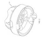
- FIG. 2is a lower perspective view of an outer link of an articulating probe of a system for performing a medical procedure according to embodiments of the present inventive concepts.
- FIGS. 3A and 3Bare perspective views of outer links of an articulating probe of a system for performing a medical procedure according to other embodiments of the present inventive concepts.
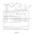
- FIG. 4is a perspective view of first and second outer links of an articulating probe of a system for performing a medical procedure according to other embodiments of the present inventive concepts.
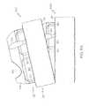
- FIG. 5Ais a side view of first and second outer links of an articulating probe of a system for performing a medical procedure according to other embodiments of the present inventive concepts.
- FIG. 5Bis a close-up side view of one of the first and second outer links of FIG. 5A .
- FIG. 5Cis a lower perspective view of the link of FIG. 5B .
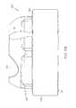
- FIG. 6Ais a lower perspective view of first and second outer links of an articulating probe of a system for performing a medical procedure according to other embodiments of the present inventive concepts.
- FIG. 6Bis a top perspective view of one of the first and second outer links of FIG. 6A .
- FIG. 6Cis a lower perspective view of the link of FIG. 6B .
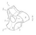
- FIG. 7Ais a lower perspective view of first and second inner links of an articulating probe of a system for performing a medical procedure according to other embodiments of the present inventive concepts.
- FIG. 7Bis a top perspective view of one of the first and second inner links of FIG. 7A .
- FIG. 8A-8Care top views of first and second outer links of an articulating probe of a system for performing a medical procedure according to other embodiments of the present inventive concepts.
- FIG. 9is a cross-sectional view of an inner link and an outer link including an anti-twist member positioned therebetween, in accordance with embodiments of the present inventive concepts.
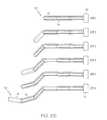
- FIGS. 10A-10Care graphic demonstrations of a highly articulated probe device, according to embodiments of the present inventive concepts.
- FIGS. 11A-11Billustrate various configurations assumed by a highly articulated probe, according to embodiments of the present inventive concepts.
- FIGS. 12A-12Dillustrate various views of a link of an outer sleeve, according to embodiments of the present inventive concepts.
- FIGS. 13A and 13Billustrate end and cross-sectional views, respectively, of a link of an inner core, according to embodiments of the present inventive concepts.
- FIGS. 14A and 14Billustrates one example of a feeder mechanism, according to embodiments of the present inventive concepts.
- FIG. 15illustrates devices for controlling the tension on cables, according to embodiments of the present inventive concepts.
- FIG. 16illustrates devices for controlling the tension on the cables of the outer sleeve, according to embodiments of the present inventive concepts.
- FIG. 17illustrates a device for controlling the tension on the cable of the inner sleeve, according to embodiments of the present inventive concepts.
- FIG. 18is a block diagram illustrating the components of a control system and the flow of information between those components, according to embodiments of the present inventive concepts.
- a flexible sheathsurrounds the spine and is axially slidably moveable relative to the spine so that the sheath will follow and conform to the shape of a spine in the rigid state and resist further flexure when the spine is in a relaxed state.
- a steerable distal tipis provided on the distal end of the device. Controls for the distal tip are mounted on the proximal end of the device. Mechanisms are provided on the distal end of the device for selectively activating and deactivating the stiffening means of the spine.
- An instrument conduitmay be mounted on the sheath.
- 11/630,279which is hereby incorporated by reference in its entirety, discloses a feeder mechanism for advancing and retracting both an inner core and an outer sleeve, as well as selectively applying tension to control cables used for steering and causing either the inner core or outer sleeve to transition between a rigid state and a limp state.
- U.S. Pat. No. 6,610,007discloses a steerable endoscope having an elongated body with a selectively steerable distal portion and an automatically controlled proximal portion.
- the endoscope bodyis inserted into a patient and the selectively steerable distal portion is used to select a desired path within the patient's body.
- an electronic motion controlleroperates the automatically controlled proximal portion to assume the selected curve of the selectively steerable distal portion.
- Another desired pathis selected with the selectively steerable distal portion and the endoscope body is advanced again.
- the selected curvespropagate proximally along the endoscope body, and when the endoscope body is withdrawn proximally, the selected curves propagate distally along the endoscope body. This creates a serpentine motion in the endoscope body allowing it to negotiate tortuous curves along a desired path through or around and between organs within the body.
- FIGS. 10A-10Care graphic demonstrations of a highly articulated probe device, according to embodiments of the present inventive concepts.
- a highly articulated robotic probe 10according to the embodiment shown in FIGS. 10A-10C , comprises essentially two concentric mechanisms, an outer mechanism and an inner mechanism, each of which can be viewed as a steerable mechanism.
- FIGS. 10A-10Cshow the concept of how different embodiments of the probe 10 operate.
- the inner mechanismcan be referred to as a first mechanism, an inner core or inner core mechanism 12 .
- the outer mechanismcan be referred to as a second mechanism, an outer sleeve or outer sleeve mechanism 14 .
- Each mechanismcan alternate between being rigid and limp.
- the mechanismIn the rigid mode or state, the mechanism is relatively inflexible such that it cannot be readily re-shaped. In the limp mode or state, the mechanism is highly flexible and thus either assumes the shape of its surroundings or can be re-shaped.
- the term “limp” as used hereindoes not denote a structure that passively assumes a particular configuration dependent upon gravity and the shape of its environment; rather, the “limp” structures described in this application are capable of assuming positions and configurations that are desired by the operator of the device, and therefore are articulated and controlled rather than flaccid and passive.
- one mechanismstarts limp and the other starts rigid.
- the outer sleeve 14is rigid and the inner core 12 is limp, as seen in step 1 in FIG. 10A .
- the inner core 12is both pushed forward by a feeding mechanism 16 , described below, and its “head” or distal end is steered, as seen in step 2 in FIG. 10A .
- the inner core 12is made rigid and the outer sleeve 14 is made limp.
- the outer sleeve 14is then pushed forward until it catches up or is coextensive with the inner core 12 , as seen in step 3 in FIG. 10A .
- the outer sleeve 14is made rigid, the inner core 12 limp, and the procedure then repeats.
- One variation of this approachis to have the outer sleeve 14 be steerable as well.
- the operation of such a deviceis illustrated in FIG. 10B .
- FIG. 10Bit is seen that each mechanism is capable of catching up to the other and then advancing one link beyond.
- the outer sleeve 14is steerable and the inner core 12 is not.
- the operation of such a deviceis shown in FIG. 10C .
- the operatorcan slide one or more tools through one or more channels of outer sleeve 14 , inner core 12 , or a channel formed between outer sleeve 14 and inner core 12 , such as to perform various diagnostic and/or therapeutic procedures.
- the channelis referred to as a working channel, that can, for example extend between first recesses formed in a system of outer links and second recesses formed in a system of inner links.
- the inner and outer linksare of a type depicted in FIGS. 1-9 described in detail herein.
- probe 10can be used in numerous applications including but not limited to: engine inspection, repair or retrofitting; tank inspection and repair; spying and surveillance applications; bomb disarming; inspection or repair in tightly confined spaces such as submarine compartments or nuclear weapons; structural inspections such as building inspections; hazardous waste remediation; biological sample recovery such as anthrax recovery; and combination of these.
- the device of the present disclosurehas a wide variety of applications and should not be taken as being limited to any particular application.
- Inner core 12 and/or outer sleeve 14are steerable and inner core 12 and outer sleeve 14 can each be made both rigid and limp, allowing probe 10 to drive anywhere in three-dimensions. Probe 10 can “remember” its previous configurations and for this reason, probe 10 can go anywhere in a three dimensional volume such as the intracavity spaces in the body of a patient such as a human patient.
- FIGS. 11A-11Billustrate examples of various configurations assumable by probe 10 .
- the outer sleeve 14 and inner core 12can be made up of concentric cylinders, outer links 22 and inner links 24 , respectively, although links of other shapes may be used, e.g. a dog bone configuration (not shown) as well as links of a type that are not concentric, e.g. backbone configuration, among others.
- the ends of the links 22 , 24are not flat but instead one end 26 is an “outer” or convex outer mating surface and the other end 28 is an “inner” or concave inner mating surface.
- the inner and outer surfacescan comprise semi-spherical surfaces with similar radii of curvature; however, as described herein, embodiments of the present inventive concepts are not limited thereto.
- the links 22are “chained”, or nested back-to-back such that the concave end 28 of one mates with the convex end 26 of an adjacent link.
- the links 24are chained, or nested back-to-back. The result is a spherical-like joint, from a kinematic point of view.
- each linkis able to rotate, or articulate on the adjacent link's head, acting as a spherical joint with approximately 10 to 20 degrees range of motion in any direction, although other ranges of motion are possible and potentially advantageous.
- the links 22have a plurality of channels 30 , or cable openings, extending therethrough to accommodate, in some embodiments, a plurality of control cables.
- the cable openings 30can be configured to accommodate elongate devices such as elongate tools.
- the heads (i.e. the distal links) of both the outer sleeve 14 and the inner core 12are steerable using three cables which are positioned at, for example, 120° from each other. As can be seen in FIGS. 12A-12D , there are three small cylindrical channels 30 respectively, for cables to pass through. In the embodiment depicted in FIGS. 13A and 13B , the inner link 24 has only one cable, in which case there is only a single hole 34 through its center.
- the links, and hence probe 10can comprise virtually any material, including plastic or other magnetic resonance imaging compatible material.
- the outer sleeve 14may assume a broad range of diameters, typically greater than 5 mm.
- inner core 12may assume a broad range of diameters, less than the diameter of outer sleeve 14 and typically more than 3 mm.
- the total number of outer links in an outer link assembly, or inner links in an inner link assembly linkscan vary over a large range but is typically greater than 10 outer or inner links.
- outer sleeve 14can be made rigid or limp using cables or other flexible filament structures.
- outer sleeve 14comprises a set of links 22 strung on three cables. The three cables can be positioned 120 degrees apart, making it possible to steer the sleeve in any direction. Radius of curvature of probe 10 is dependent on a number of factors including length of links 22 as well as mating dimensions between the ends of mating links 22 .
- the outer sleeve 14When the pulling force is released, the outer sleeve 14 becomes limp.
- the cables together with their respective tensioning assembliesform a locking device.
- the distal link of the outer sleeve 14can be oriented by pulling one or more of the three cables.
- the magnitude of the pulling force which is exerted on each cablecan be monitored or controlled. By pulling the three cables with the same magnitude, the outer sleeve 14 becomes rigid without changing its shape.
- the inner core 12like the outer sleeve 14 , consists of a set of links. According to one embodiment, in contrast to the outer sleeve 14 , the inner core 12 does not require a steering ability. In some embodiments, a steering feature is optional, and can be employed, in connection with the inner core 12 . In some embodiments, the inner core 12 can change between a rigid mode and a limp mode. Therefore, in embodiments where the inner core 12 need not be steerable, the links of the inner core 12 may be strung on a single cable, which enables a reduced diameter for probe 10 .
- a feeding mechanism 16can be used to control the probe 10 .
- One type of feeding mechanism 16shown in FIGS. 14A and 14B , inserts and retracts the probe 10 into and out of respectively, a region of interest such as the esophagus, the peritoneal space, the pericardial cavity, or another internal space of a patient.
- the feeder 16has two movable carts. A first cart 42 , carried in a first fixed tray 43 , advances and retracts the outer sleeve 14 while a second cart 44 carried in a second fixed tray 45 advances and retracts the inner core 12 .
- Each cart 42 , 44 , and hence, each of the inner core 12 and outer sleeve 14is driven independently by separate linear actuators 46 , 48 respectively.
- the linear actuators 46 , 48may carry shaft encoders (not shown) used for position control as is known to those of skill in the art.
- motor currentmay be monitored to determine a value for tension in a cable used to control position.
- Cable tensionmay be monitored with one or more sensors such as a load cell. Numerous positioning and other sensors may be included to provide information relative to cable tension; cart position; probe orientation and configuration; and other system parameters.
- Typical sensorsinclude but are not limited to: optical sensors; magnetic sensors such as Hall effect sensors; force and pressure sensors such as accelerometers, strain gauges and mechanical switches; and combinations of these.
- One or more sensorsmay be positioned in multiple locations including but not limited to: feeding mechanism 16 , inner core 12 and outer sleeve 14 .
- Each of the carts 42 , 44carries one or more motors necessary for controlling the cables of the inner core 12 and outer sleeve 14 .
- the cart 42carries motors 50 , 51 , 52 which control the tension on cables 54 , 55 , 56 of outer sleeve 14 .
- second cart 44has a motor 58 for controlling the tension on cable 59 of the inner core 12 .
- Each of the motors 50 , 51 , 52 and 58may be provided with shaft encoders (not shown) used for position control as is known.
- the inner core 12requires two or more motors (e.g. to tension two or more cables) or another cable tensioning mechanism.
- FIG. 18is a block diagram illustrating the components of one embodiment of a control system and the flow of information between those components.
- the feeding mechanism 16interfaces with a control computer 62 through a bus conversion module 64 .
- Outgoing data from the feeding mechanism 16is input to the module 64 for conversion to a communication protocol, such as USB protocol, and is then input to a USB port 66 on the computer 62 .
- Incoming data to control software 68may include motor current data, motor encoder data and/or cable tension data associated with each of the cables in the feeding mechanism 16 .
- incoming data to control software 68may include data from one or more sensors located in feeding mechanism 16 , an inner core or an outer sleeve such as inner core 12 or outer sleeve 14 described herein.
- Joystick datamay also be received from a joystick 70 .
- a monitor 72may be responsive to video data from a camera mounted on the distal end of the outer sleeve 14 and/or inner core 12 to provide visual feedback to a user regarding the position of the distal end of the probe 10 .
- the control software 68may output motor current limit commands and motor position commands which are input to the feeding mechanism 16 .
- the outer sleeve link systems and inner core link systemsare subject to twisting, from link to link.
- an inherent amount of twistingcan occur between neighboring links. Twisting of links can be cumulative over the system of links. Accordingly, while the angle of misalignment can be minor from individual neighboring link to link, the total amount of twisting of the distal link of the system relative to the proximal link can be large. As the number of links in a system increases, so too can the amount of cumulative twist. Such twisting can adversely affect the performance of the articulating probe.
- Twistingcan occur due to a number of factors, including a difference between the outer radii of the steering cables and the inner radii of the steering cable openings.
- the neighboring linksmay become misaligned prior to, or during, a procedure.
- the twisting of links relative to each othercan cause an inconsistent relation of steering input to steering output. Loss of alignment between user and robot coordinate systems can occur. As a result, for an operator to initiate a turn in a particular direction, the robot must be moved in a different direction to compensate for twist.
- links that are twisted relative to each othermay be subject to a limited range of steering. Twisting can also cause neighboring links to become inadvertently locked together, and the steering cables can become pinched in the gaps between over-twisted links.
- twistingcan include the binding of instruments inserted through internal channels of the link systems, possible occlusion of internal tool channels, as well as increased wear on electrical conduits present in the system. Twisting can also result in increased wear and friction between inner and outer links, causing neighboring links to bind, or preventing their ability to advance during a procedure. Also, twisting can result in the misalignment between the end of the probe and the target anatomy.
- Twisting between neighboring linkscan be as severe as 5 degrees of offset. Cumulative twisting of a distal link relative to a proximal link in a link system can be as large as 45 degrees. Embodiments described herein are directed to systems and methods for resisting or preventing the amount of twist of a second neighboring link relative to a first link, while still allowing for articulation of the links for steering purposes.
- FIG. 1Ais a side view of first and second outer links of an articulating probe of a system for performing a medical procedure according to embodiments of the present inventive concepts.
- FIG. 1Bis a lower perspective view of the first and second outer links of FIG. 1A .
- FIG. 1Cis a cutaway side view of the first and second outer links of FIG. 1A .
- FIG. 1Dis a cutaway side view of the first and second outer links of FIG. 1A illustrated with the second link articulated relative to the first link.
- FIG. 1Eis a side perspective view of one of the first and second outer links of FIG. 1A .
- first and second outer links 100 a , 100 b (generally 100 ) of the articulating probeare each constructed and arranged to have a longitudinal axis 102 Za, 102 Zb, an articulation joint (joint formed from articulating surfaces 104 and 110 shown specifically in FIG. 1C ) and motion-limiting element 106 .
- Multiple outer links 100are stacked and nested relative to each other.
- the linksare configured to articulate relative to each other and are prevented from separating relative to each other by steering cables 109 (see FIG. 1B ) that pass through one or more steering cable openings 108 of the multiple links 100 .
- three steering cable openings 108 and three cables 109are shown (see FIG. 1B ); however fewer or more steering cable openings and steering cables can be employed, depending on the application of the articulating probe.
- the articulation jointcomprises a convex articulation surface 104 a of the first outer link 100 a and a concave articulation surface 110 b of the second outer link 100 b .
- the convex and concave surfacesengage each other throughout a range of articulation of the second outer link 100 b relative to the first outer link 100 a , under control of the steering cables 109 .
- Tension that is present in at least one of the steering cables 109 , at any given time, between the proximal and distal ends of the articulating proberetain the articulating joints of the various links of the assembly in place.
- the respective longitudinal axes 102 Za, 102 Zb of the first and second outer links 100 a , 100 bare substantially in alignment with each other, or at an angle of zero degrees with respect to each other.
- the second outer links 100 bcan be considered to be in a non-articulated position relative to the first outer link 100 a .
- the second longitudinal axis 102 Zb of the second link 100 bis at a non-zero angle relative to the first longitudinal axis 102 Za of the first link 100 a .
- the second outer link 100 bcan be considered to be in an articulated position relative to the first outer link 100 a.
- FIG. 2is a lower perspective view of an outer link of an articulating probe of a system for performing a medical procedure according to embodiments of the present inventive concepts.
- first and second articulation axes 102 X, 102 Y of the outer linkare illustrated.
- the first and second articulation axes 102 X, 102 Yare normal to each other and normal to the longitudinal axis 102 Z of the outer link.
- a second outer link 100 b neighboring a first outer link 100 awill be permitted to articulate over a range of angles about the first articulation axis 102 X as illustrated by arrow 103 X and will be permitted to articulate over a range of angles about the second articulation axis 102 Y as illustrated by arrow 103 Y, relative to the first and second articulation axes of the first outer link 100 a .
- articulationis permitted or allowed in two degrees of freedom. Twisting or rotation of the second outer link 100 b relative to a neighboring first outer link 100 a in the direction illustrated by arrow 103 Z is undesirable, for various reasons described herein.
- Embodiments of the present inventive concepts described hereininclude a motion-resisting assembly of any of a number of various types for limiting, mitigating or otherwise resisting rotation or twisting of a second outer link relative to a neighboring first outer link of the articulating probe assembly, or of a second inner link relative to a neighboring first inner link of the articulating probe assembly.
- first and second outer links 100 a , 100 beach include a motion limiting element, pin 106 (also visible in the perspective view of FIG. 1E ), that operates in conjunction with a corresponding slot 112 of a neighboring link to provide a motion resisting assembly 106 , 112 suitable for limiting rotation of the second link 100 b relative to the first link 100 a .
- motion resisting assembly 106 , 112is suitable for limiting rotation of the second link 100 b about its longitudinal axis 102 Zb relative to the longitudinal axis 102 Za of the first link 100 a.
- the motion resisting assembly 106 , 112operates to limit rotation of the first link 100 a relative to the second link 100 b .
- the motion resisting assembly 106 , 112can be said to limit rotation of the first link 100 a and the second link 100 b relative to each other.
- the pin 106extends in an outward direction from a lower portion of the convex articulation surface 104 of the outer link 100 .
- the pin 106can be positioned at, or along, an equator of the semi-spherical surface.
- the pin 106may be circular in cross-section to allow for pivoting of a slot 112 of a neighboring link during articulation.
- the pin 106can have a cross-sectional shape that is other than circular.
- the slot 112can be formed in a pin extension or tab 114 that extends from a lower portion of the link 100 .
- the slot 112can have a width W (see FIG. 1B ) that is sized to accommodate the pin 106 width.
- the pin 106can be permitted to slide freely along the slot 112 in a direction of extension of the slot, while limiting gaps or play of the pin 106 between the sidewalls of the slot 112 .
- the slot 112can have a length L that is sufficient to allow the pin 106 to slide between a range of desired articulation of neighboring links 100 a , 100 b .
- a top portion of the slot 112can be rounded to interface with the rounded, corresponding pin 106 .
- each link 100includes two pins 106 and two pin slots 112 for mating with pins of neighboring links.
- Each linkcan include a single pin 106 , or more than two pins, or a single slot 112 , or more than one slot 112 , depending on the application.
- the first link 100 ais in alignment with the second link 100 b so that their respective longitudinal axes 102 Za, 102 Zb are in alignment.
- the first and second pins 106are at least partially engaged with the respective first and second slots 112 of the neighboring second link 100 b .
- the second link 100 bis prevented, or otherwise limited, from rotating or twisting, about its longitudinal axis 102 Zb, relative to the longitudinal axis 102 Za of the first link 100 a , as the first and second pins 106 are engaged with their respective mating slots 112 .
- the sidewalls of the slots 112 of the second linkabut the pins 106 of the first link 100 a and thus prevent the first link 100 b from rotating about its longitudinal axis 102 Zb.
- the interaction of the pins 106 and slots 112do not obstruct or limit articulation of the second link 100 b relative to the first link 100 a , for example articulation of the second link 100 b about the first and second articulation axes 102 x , 102 y of the first link 100 a (see FIG. 2 ). Free articulation of the second link 100 b relative to the first link 100 a is maintained, while mitigating or preventing undesired twisting of the second link relative to the first link.
- the links 100 a , 100 beach include a lower portion 126 and an upper portion 128 .
- the lower portion 126includes the concave articulation surface 110 and the upper portion 128 includes the convex articulation surface 104 which combine to form the articulation joint.
- a shoulder 120can be provided at an interface of the outer surfaces of the lower portion 126 and the upper portion 128 .
- the shoulder 120 of a first link 100 a and a lower surface 121 of the second link 100 boperate to limit the amount of articulation of the second link 100 b relative to the first link 100 a .
- articulationcan be limited to an angle that corresponds to the position at which the lower surface 121 of the second link 100 b physically abuts the shoulder 120 of the first link 100 a.
- a recess 122can be formed in the shoulder 120 of the lower portion.
- the recess 122can be formed to have a shape that accommodates the pin extension or tab 114 .
- the slot 112 of the tab 114can engage its corresponding pin 106 , while maintaining the outer profile of the links 100 a , 100 b so that their outer perimeters are not increased.
- the tab 114 and corresponding recess 122can be constructed and arranged so that they do not limit articulation of the second link 100 b relative to the first link 100 a .
- the shoulder 120 of the first link 100 amakes contact with the lower surface 121 of the neighboring link 100 b while a clearance is maintained between the tab 114 and the surface of the corresponding recess 122 .
- the tab 114 and corresponding recess 122can be configured so that the interface of the tab 114 and recess 122 provides an articulation-limiting function, while a clearance is maintained between the shoulder 120 and corresponding lower surface 121 of the neighboring links 100 a , 100 b.
- the links 100 a , 100 bcomprise outer links of an articulating probe having a plurality of articulating inner links and a plurality of articulating outer links.
- recesses 124are provided at an interface between inner regions of the outer links and corresponding outer regions of the inner links. The recesses 124 correspond to working channels of the articulating probe to allow for delivery of functional elements from the proximal end to the distal end of the articulating probe, as described herein.
- the convex articulation surface 104 a of the first outer link 100 acomprises a semi-spherical convex surface and the concave articulation surface 110 of the second outer link 100 b comprises a semi-spherical concave surface.
- the radius of the convex articulation surface 104 a of the first outer link 100 acan be the same as the radius of the concave articulation surface 110 b of the second outer link 100 b .
- the radius of the convex articulation surface 104 a of the first outer link 100 acan be greater than the radius of the concave articulation surface 110 b of the second outer link 100 b . In some embodiments, the radius of the convex articulation surface 104 a of the first outer link 100 a can be less than the radius of the concave articulation surface 110 b of the second outer link 100 b.
- the convex articulation surface 104 a of the first outer link 100 acomprises a semi-spherical convex surface and the concave articulation surface 110 b of the second outer link 100 b comprises a semi-conical concave surface.
- variation in the spherical diametercan affect the amount of surface contact between the convex and concave surfaces. This can result in variation of the steering forces, variation in the amount of compression between neighboring links and binding of the articulation surfaces.
- any variation in the convex surface as a result of manufacturing or usehave little effect on the contact angle and location of contact between the convex and concave articulation surfaces.
- Variations in the size of the convex surfacemay have an effect on how far into the semi-conical surface the convex surface engages, but, owing to the geometry, the contact angle will be the same, despite the variations.
- the angle of the semi-conical surfacecan be varied to accommodate tradeoffs between steerability and payload of the resulting articulating probe.
- the angle of the semi-conical surfacecontrols the contact point between the convex, semi-spherical and the concave, semi-conical articulation surfaces. In general, as the contact point is lowered to a wider region of the cone, the strength of the interface, and therefore the strength of the articulating probe, is improved. As the contact point is raised to a narrower region of the cone, steerability of the articulating probe is improved.
- the angle of the semi-conical surfacecan be approximately 23°, or 46° included. This angle can be suitable when considering the combined factors of outer link geometry, material strength, and material friction properties.
- a range of angleswere subject to testing, and compression testing indicated that the 23 degree conical provided optimal compression, in other words, the least amount of compression, as a result of where the concave conical surface comes in contact with the convex spherical mating surface, while still providing optimal friction for locking ability in a rigid state, as recorded in friction/steering test results.
- Steeper anglesfor example a 14 degree angle, resulted in the outer links sticking or binding to each other under compression, while more gradual angles, for example, angles greater than about 23 degrees resulted in reduced locking while in a rigid state.
- conical angles less than 23 degrees or greater than 23 degreesmay be desirable.
- the system of outer links 100employ three steering cables spaced apart from each other at 120 degree intervals.
- the steering cablesare selectively tensioned to retain the articulation surfaces of the links in a rigid position and are selectively released to allow for selective motion of the links in a limp position.
- Other numbers of steering cablescan be employed, for example two, four, or more, and they can be spaced apart at regular angular intervals or at different angles.
- FIG. 3Ais a perspective view of first and second outer links of an articulating probe of a system for performing a medical procedure according to other embodiments of the present inventive concepts.
- the motion resisting assemblycomprises one or more slots 312 positioned on an external portion of the convex articulation surface 304 of the link 100 c , 100 d .
- the motion resisting assemblyfurther comprises one or more corresponding pins 306 , in this example two opposed pins, that are positioned on tabs 314 configured to engage the corresponding slots 312 of a neighboring link 100 c , 100 d.
- the convex articulation surface 304 of the links 100 c , 100 dis semi-spherical.
- the pins 306 of a neighboring second link 100 dcan be positioned such that when the neighboring links are at an articulation angle of zero, and therefore, their respective longitudinal axes are aligned, the pins 306 of the neighboring second link 100 d are aligned with the equator of the semi-spherical convex articulation surface 304 of the first link 100 c .
- the slots 312can be oriented to extend along the outer surface of the semi-spherical convex articulation surface 304 in a direction that is along a meridian curve, or longitude curve, from the equator of the surface 304 to a pole of the surface 304 .
- the length L of the slots 312can be extended beyond the equator of the surface 304 , to accommodate articulation of the neighboring second link 100 d relative to the first link 100 c .
- the lower surface 321 of the second link 100 dabuts a shoulder 320 of the first link 100 c to limit articulation.
- a recess 322 formed in the shoulder 320accommodates the tab 314 in this position, without interfering with free articulation of the second link 100 d relative to the first link 100 c .
- the tab 314 and corresponding recess 322can be configured to provide an articulation-limiting function.
- the sidewalls of the slots 312 of the first link 100 cabut the pins 306 of the second link 100 d and thus prevent the second link 100 d from rotating about its longitudinal axis relative to the first link 100 c .
- the interaction of the pins 306 and slots 312do not obstruct or limit articulation of the second link 100 d relative to the first link 100 c , for example articulation of the second link 100 d about the first and second articulation axes 102 x , 102 y of the first link 100 c (see FIG. 2 ). Free articulation of the second link 100 d relative to the first link 100 c is maintained, while mitigating or preventing undesired twisting of the second link 100 d relative to the first link 100 c
- two pins 306 and slots 312can be positioned on each link 100 c , 100 d at opposed 180 degree positions, as shown in FIG. 3A .
- a single pin 306 and a single slot 312can be positioned on each link 100 d ′, 100 d ′′, 100 d ′′′.
- the pin 306 and slot 312 of each link 100 d ′, 100 d ′′, 100 d ′′′can be positioned at an angular distance of 120 degrees apart from each other about the perimeter of the link 100 d ′, 100 d ′′, 100 d ′′′.
- each respective link 100 d ′, 100 d ′′, 100 d ′′′can be seated into its respective position by rotating each link by 120 degrees relative to the neighboring link as the links progress from the proximal end to the distal end of the articulating probe.
- Engagement of the single pin 306 and slot 312is sufficient for mitigating or preventing undesired twisting of the link 100 d ′′ relative to an adjacent link, e.g. 100 ′ and 100 ′′′, since the pin 306 and corresponding slot 112 remain engaged throughout the range of articulation.
- FIG. 4is a perspective view of first and second outer links of an articulating probe of a system for performing a medical procedure according to other embodiments of the present inventive concepts.
- the motion resisting assemblycomprises one or more pins 406 positioned on an external portion of the convex articulation surface 404 of the link 400 a , 400 b .
- the motion resisting assemblyfurther comprises one or more corresponding slots 406 that are positioned within the concave articulation surface 410 a and configured to engage the corresponding pins 406 of a neighboring link 400 a , 400 b .
- a single pin 406 and a single corresponding slot 412are used.
- the convex articulation surface 404 of the links 400 a , 400 bis semi-spherical.
- the pin 406 of each linkcan be positioned to lie on the convex articulation surface 404 at a position above the equator of the semi-spherical convex articulation surface 404 , and between the equator and the pole of the surface 404 .
- the slots 412can be oriented to extend along the inner surface of the semi-spherical concave articulation surface 410 a in a direction that is oriented along a meridian curve, or longitudinal curve, from the equator of the surface 410 a toward a pole of the surface 410 a .
- the length L of the slots 412can accommodate articulation of the neighboring second link 400 b relative to the first link 400 a .
- the lower surface 421 of the second link 400 babuts a shoulder 420 of the first link 400 a to limit articulation.
- the sidewalls of the slot 412 of the second link 400 babut the pin 406 of the first link 400 a and thus prevent the second link 400 b from rotating about its longitudinal axis relative to the first link 400 a .
- the interaction of the pin 406 and slot 412do not obstruct or limit articulation of the second link 400 b relative to the first link 400 a , for example articulation of the second link 400 b about the first and second articulation axes 102 x , 102 y of the first link 400 a (see FIG. 2 ). Free articulation of the second link 400 b relative to the first link 400 a is maintained, while mitigating or preventing undesired twisting of the second link 400 b relative to the first link 400 a.
- FIG. 5Ais a side view of first and second outer links of an articulating probe of a system for performing a medical procedure according to other embodiments of the present inventive concepts.
- FIG. 5Bis a close-up side view of one of the first and second outer links of FIG. 5A .
- FIG. 5Cis a lower perspective view of the link of FIG. 5B .
- the motion resisting assemblycomprises a plurality of lobes, or ribs, 150 , spaced apart from each other about an outer perimeter of the convex articulation surface 104 of the link 100 e , 100 f .
- the convex articulation surface 104is semi-spherical and the plurality of lobes 150 are spaced apart about an equator region of the convex articulation surface 104 .
- the lobes 150can be placed between the equator region and the polar region of the convex articulation surface.
- the lobes 150can be linked to each other by planar outer linking surfaces 152 ; however, the linking surfaces can alternatively be curved or angular, depending on the application.
- the motion resisting assemblyfurther comprises a plurality of recesses 154 spaced apart from each other about an inner surface of the lower portion of the concave articulation surface 110 .
- the recesses 154are similarly linked to each other by planar inner linking surfaces 156 , which otherwise can also be curved or angular, depending on the application.
- the lobes 150 and outer linking surfaces 152 of a first neighboring link 100 eare positioned to correspond with the recesses 154 and inner linking surfaces 156 of a second neighboring link 100 f .
- At least one of the plurality of recesses 154 and/or planar inner linking surfaces 156remains engaged with the corresponding lobes 150 and/or outer linking surfaces 152 of the neighboring link.
- at least top portions of all lobes 150 and outer linking surfaces 152can be in position to engage at least bottom portions of all recesses 154 and inner linking surfaces 156 .
- the inner walls of the recesses 154 and inner linking surfaces 156 of the second link 100 fabut the lobes 150 and outer linking surfaces 152 of first link 100 e and thus prevent the second link 100 f from rotating about its longitudinal axis.
- the interaction of the recesses and lobes 154 , 150 and inner and outer linking surfaces 156 , 152do not obstruct or limit articulation of the second link 100 f relative to the first link 100 e , for example articulation of the second link 100 f about the first and second articulation axes 102 x , 102 y of the first link 100 e (see FIG. 2 ). Free articulation of the second link 100 f relative to the first link 100 e is maintained, while mitigating or preventing undesired twisting.
- any of a number of lobes 150 and recesses 154can be employed.
- any of two through eight, or more, lobes 150can be employed and two through eight, or more, recesses 154 can be employed.
- the number of lobes 150can be the same as, or different than the number of recesses 154 .
- the lobes and/or recessescan be evenly distributed at angular intervals about the links or can be unevenly distributed.
- the outer linking surfaces 152can be planar, or otherwise curved or angular, depending on the application.
- the inner linking surfaces 156can be planar, or otherwise curved or angular, depending on the application
- FIG. 6Ais a lower perspective view of first and second outer links of an articulating probe of a system for performing a medical procedure according to other embodiments of the present inventive concepts.
- FIG. 6Bis a top perspective view of one of the first and second outer links of FIG. 6A .
- FIG. 6Cis a lower perspective view of the link of FIG. 6B .
- the motion resisting assemblycomprises a convex first articulation surface 604 on an upper portion 128 of a first link 100 g and a concave second articulation surface 610 in a lower portion of a second link 100 h neighboring the first link 100 g.
- the convex first articulation surface 604is semi-ellipsoidal.
- the concave second articulation surface 610is semi-ellipsoidal.
- the semi-ellipsoidal surfacehas a major axis Amajor and a minor axis Aminor in the plane of the first and second articulation axes 102 x , 102 y (see FIG. 2 ). Referring to FIGS. 6B and 6C , the major axis Amajor can have a greater length than the minor axis Aminor for both the convex first articulation surface 604 and the concave second articulation surface 610 .
- Interaction of the corresponding convex and concave semi-ellipsoidal articulation surfaces 604 , 610 of the neighboring linkspermit free articulation of the second link 100 h relative to the first link 100 g .
- the articulationcan be limited for example, by positioning of the lower surface 121 of the second link 100 h relative to the shoulder 120 of the first link 100 g , as described herein in connection with various other embodiments.
- the elongated shapes of the mating semi-ellipsoidal surfaces 604 , 610 of the neighboring linksprevent the second link 100 h from rotating about its longitudinal axis 602 Zh relative to the longitudinal axis 602 Zg of the first link 100 g .
- the interaction of the semi-ellipsoidal surfaces 604 , 610does not obstruct or limit articulation of the second link 100 h relative to the first link 100 g , for example articulation of the second link 100 h about the first and second articulation axes 102 x , 102 y of the first link 100 g (see FIG. 2 ). Free articulation of the second link 100 h relative to the first link 100 g is maintained, while mitigating or preventing undesired twisting of the second link relative to the first link.
- FIG. 7Ais a lower perspective view of first and second inner links of an articulating probe of a system for performing a medical procedure according to other embodiments of the present inventive concepts.
- FIG. 7Bis a top perspective view of one of the first and second inner links of FIG. 7A .
- the motion resisting assemblycomprises a first articulation surface 704 on an upper surface of a first link 700 i and a second articulation surface 710 on a lower surface of a second link 700 j neighboring the first link 700 i.
- the first and second links 700 i , 700 jcomprise inner links of the articulating probe.
- the first and second inner links 700 i , 700 jare configured to be positioned within the longitudinal openings present in the arrangement of outer links.
- the first and second links 700 i , 700 j(generally 700 ) include a central cable opening 732 that passes through the links 700 in a longitudinal direction of the links 700 along their respective longitudinal axes 702 Zi, 702 Zj.
- the cable opening 732is configured to receive an operating cable for the inner mechanism of the articulating probe.
- the outermost surface portions 734 of the first and second linkslie on a circle.
- recesses 724can be provided to accommodate working channels of the articulating probe that are formed between the inner regions of the outer links and outer regions of the inner links, as described herein. In a case where three working channel recesses 724 are present, then the links are generally shaped to have three lobe regions 736 a - c surrounding the cable opening 732 .
- the first articulation surface 704comprises convex features and concave features.
- the first articulation surface 704is convex in profile between points G and H on the surface 704 between the first and second lobes 736 a , 736 b .
- the first articulation surface 704is concave in profile between points E and F on the surface 704 between the third lobe 736 c and the saddle region 738 between the first and second lobes 736 a , 736 b.
- the second articulation surface 710as shown in FIG. 7A comprises concave features and convex features that correspond with those of the first articulation surface 704 of a neighboring link.
- the second articulation surface 710is concave in profile between points C and D on the surface 710 between the first and second lobes 736 a , 736 b .
- the second articulation surface 710is convex in profile between points A and B on the surface 710 between the third lobe 736 c and the saddle region 738 between the first and second lobes 736 a , 736 b.
- the convex features of the first articulation surface 704mate with, or otherwise interface with, the concave features of the second articulation surface 710 of a neighboring link.
- the concave features of the first articulation surface 704mate with, or otherwise interface with, the convex features of the second articulation surface 710 of a neighboring link.
- Interaction of the corresponding convex and concave features of the first and second articulation surfaces 704 , 710 of the neighboring linkspermit free articulation of the second link 700 j relative to the first link 700 i .
- the concave feature between points C and D of the second articulation surface interacting with the corresponding feature on the neighboring first articulation surfacepermits free articulation in a first plane; while the convex feature between points A and C of the second articulation surface interacting with the corresponding feature on the neighboring first articulation surface permits free articulation in a second plane.
- the opposed convex and concave features of the first and second articulation surfaces 704 , 710prevent the second link 700 j from rotating about its longitudinal axis 702 Zj relative to the longitudinal axis 702 Zi of the first link 700 i , or otherwise limit or mitigate such rotation.
- the interaction of the opposed convex and concave featuresdoes not obstruct or limit articulation of the second link 700 j relative to the first link 700 i , for example articulation of the second link 700 j about the first and second articulation axes 702 x , 702 y of the first link 700 i . Free articulation of the second link 700 j relative to the first link 700 i is maintained, while mitigating or preventing undesired twisting of the second link relative to the first.
- inventive concepts of the present embodimentincluding opposed and mating convex and concave features is not only applicable to inner links 700 , but also can be applied to the outer links 100 of the articulating probe.
- FIG. 8A-8Care top views of first and second outer links of an articulating probe of a system for performing a medical procedure according to other embodiments of the present inventive concepts.
- first magnets 802 kare positioned about the shoulder 120 of a first link 800 k .
- the first magnets 802 kcan be positioned at regular angular intervals about the shoulder 120 . In the present example embodiment, a 90 degree interval is illustrated.
- second magnets 802 lare positioned about the lower surface 121 of a second link 800 l to correspond with those of the first link.
- the ends of the first magnets 802 k positioned on the shoulder 120 of the first link 800 khave a first polarity, for example South (S), and ends of the second magnets 802 l positioned on the lower surface 121 of the second link 800 l have a second polarity, for example, North (N).
- mating pairs of the first and second magnets 802 k , 802 lcan be selected so as to have opposite polarities, and the polarities of all magnets of a given link do not need to have the same orientation.
- first magnets 802 mare positioned about the convex first articulating surface 804 of a first link 800 m .
- the first magnets 802 mcan be positioned at regular angular intervals about first articulating surface 804 . In the present example embodiment, a 90 degree interval is illustrated.
- second magnets 802 nare positioned about the concave second articulating surface 810 of a second link 800 n to correspond with those of the first link 800 m .
- first magnets 802 m positioned on the first link 800 mhave a first polarity, for example South (S), and the second magnets 802 n positioned on the second link 800 n have a second polarity, for example, North (N).
- mating pairs of the first and second magnets 802 m , 802 ncan be selected so as to have opposite polarities, and the polarities of all magnets of a given link do not need to have the same orientation.
- first magnetic strips 802 pare positioned circumferentially about the convex first articulating surface 804 of a first link 800 p .
- the first magnetic strips 802 pcan be positioned at regular angular intervals about first articulating surface 804 . In the present example embodiment, two strips at a 180 degree interval are illustrated.
- second magnetic strips 802 qare positioned about the concave second articulating surface 810 of a second link 800 q and are oriented to correspond with those of the first link 800 p .
- first magnetic strips 802 p positioned on the first link 800 phave a first polarity, for example South (S), and the second magnetic strips 802 q positioned on the second link 800 q have a second polarity, for example, North (N).
- mating pairs of the first and second magnets 802 p , 802 qcan be selected so as to have opposite polarities, and the polarities of all magnets of a given link do not need to have the same orientation.
- the first and second magnetsare positioned so as to magnetically engage each other over a range of articulation angles of the second link relative to the first link.
- the magnetic engagement between the magnets of the neighboring linkspermits articulation of the second link relative to the first link.
- the articulationcan be limited for example, by positioning of the lower surface 121 of the first link relative to the shoulder 120 of the second link, as described herein in connection with various other embodiments.
- the magnetic interaction of the neighboring linksprevent the second link from rotating about its longitudinal axis relative to the longitudinal axis of the first link, or otherwise limit or mitigate such rotation.
- the magnetic interactiondoes not obstruct or limit articulation of the second link relative to the first link. Free articulation of the second link relative to the first link is maintained, while mitigating or preventing undesired twisting of the second link relative to the first.
- the embodiments illustrated in FIGS. 8A-8Ccan be employed in connection with any of the other embodiments described herein to further restrict or limit twisting of the links.
- the magnetsare illustrated as being applied to outer links of the articulating probe, however, the principles of this concept of the invention are equally applicable to inner links, as well.
- FIG. 9is a cross-sectional view of an inner link and an outer link including an anti-twist member positioned therebetween, in accordance with embodiments of the present inventive concepts.
- an articulating probeincludes an assembly of outer links 100 r having a central opening.
- An assembly of inner links 700 sis positioned through the central opening of the inner links.
- the plurality of outer links 100 rhave recesses 124 on their inner sidewalls and the plurality of inner links 700 s have recesses 724 on their outer sidewalls. Together, the opposed recesses 124 , 724 form working channels for the articulating probe for the purposes described herein, and for other purposes.
- an anti-twist member 942is positioned in at least one of the working channels 125 .
- the anti-twist membercomprises a tube-shaped member that is hollow or solid in cross-section.
- the anti-twist member 942comprises a flexible material that permits articulation of neighboring inner links and articulation of neighboring outer links.
- the tubecan exhibit strength or rigidity when subjected to a twisting motion between neighboring links.
- the anti-twist member 942can be configured to extend along an entire length, or nearly the entire length, of the working channel 125 of the articulating probe, from its proximal to distal end.
- the anti-twist member 942can be segmented so that it extends through portions of the working channel 125 . In some embodiments, the anti-twist member 942 can be affixed to a recess 724 of the inner link 700 s or a recess 124 of the outer link 100 r . In some embodiments, the anti-twist member 942 can be affixed to both a recess 724 of the inner link 700 s and a recess 124 of the outer link 100 r.
- the tube-shaped anti-twist member 942can be fixed at its proximal and distal ends.
- the torsional rigidity of the anti-twist member 942will determine the degree to which it prevents twisting.
- the presence of the anti-twist memberprevents the second link from rotating about its longitudinal axis relative to the longitudinal axis of the first link.
- the anti-twist memberdoes not obstruct or limit, or minimally obstructs or limits, articulation of the second link relative to the first link. Free articulation of the second link relative to the first link is maintained, while mitigating or preventing undesired twisting.
- the embodiments illustrated in FIG. 9can be employed in connection with any of the other embodiments described herein to further restrict or limit twisting of the links.
- the systems and methods of the present inventive conceptsprevent, mitigate, or otherwise restrict, torsional rotation, or twisting, of links in a system of links in a highly articulated robotic system.
- the systems and methodscan be applied to both an inner link mechanism and an outer link mechanism of the robotic system.
- rotation of a second link relative to a first linkcan be limited to about 1 degree of rotation.
- Other rotational limit amountsare equally applicable, depending on the configuration, and the inventive concepts are not limited thereto.
Landscapes
- Health & Medical Sciences (AREA)
- Engineering & Computer Science (AREA)
- Life Sciences & Earth Sciences (AREA)
- Surgery (AREA)
- Robotics (AREA)
- Veterinary Medicine (AREA)
- Nuclear Medicine, Radiotherapy & Molecular Imaging (AREA)
- Biomedical Technology (AREA)
- Heart & Thoracic Surgery (AREA)
- Medical Informatics (AREA)
- Molecular Biology (AREA)
- Animal Behavior & Ethology (AREA)
- General Health & Medical Sciences (AREA)
- Public Health (AREA)
- Mechanical Engineering (AREA)
- Physics & Mathematics (AREA)
- Biophysics (AREA)
- Optics & Photonics (AREA)
- Pathology (AREA)
- Radiology & Medical Imaging (AREA)
- Rehabilitation Therapy (AREA)
- Surgical Instruments (AREA)
- Manipulator (AREA)
- Ultra Sonic Daignosis Equipment (AREA)
- Endoscopes (AREA)
- Measuring Pulse, Heart Rate, Blood Pressure Or Blood Flow (AREA)
- Length Measuring Devices With Unspecified Measuring Means (AREA)
- A Measuring Device Byusing Mechanical Method (AREA)
Abstract
Description
Claims (50)
Priority Applications (1)
| Application Number | Priority Date | Filing Date | Title |
|---|---|---|---|
| US14/343,915US9757856B2 (en) | 2011-09-13 | 2012-09-12 | Highly articulated probes with anti-twist link arrangement, methods of formation thereof, and methods of performing medical procedures |
Applications Claiming Priority (6)
| Application Number | Priority Date | Filing Date | Title |
|---|---|---|---|
| US201161534032P | 2011-09-13 | 2011-09-13 | |
| US201161578582P | 2011-12-21 | 2011-12-21 | |
| US201261656600P | 2012-06-07 | 2012-06-07 | |
| US201261681340P | 2012-08-09 | 2012-08-09 | |
| US14/343,915US9757856B2 (en) | 2011-09-13 | 2012-09-12 | Highly articulated probes with anti-twist link arrangement, methods of formation thereof, and methods of performing medical procedures |
| PCT/US2012/054802WO2013039999A2 (en) | 2011-09-13 | 2012-09-12 | Highly articulated probes with anti-twist link arrangement, methods of formation thereof, and methods of performing medical procedures |
Related Parent Applications (1)
| Application Number | Title | Priority Date | Filing Date |
|---|---|---|---|
| PCT/US2012/054802A-371-Of-InternationalWO2013039999A2 (en) | 2011-09-13 | 2012-09-12 | Highly articulated probes with anti-twist link arrangement, methods of formation thereof, and methods of performing medical procedures |
Related Child Applications (2)
| Application Number | Title | Priority Date | Filing Date |
|---|---|---|---|
| US15/064,043ContinuationUS9572628B2 (en) | 2011-09-13 | 2016-03-08 | Highly articulated probes with anti-twist link arrangement, methods of formation thereof, and methods of performing medical procedures |
| US15/684,268ContinuationUS20170368681A1 (en) | 2011-09-13 | 2017-08-23 | Highly articulated probes with anti-twist link arrangement, methods of formation thereof, and methods of performing medical procedures |
Publications (2)
| Publication Number | Publication Date |
|---|---|
| US20140371764A1 US20140371764A1 (en) | 2014-12-18 |
| US9757856B2true US9757856B2 (en) | 2017-09-12 |
Family
ID=47883938
Family Applications (3)
| Application Number | Title | Priority Date | Filing Date |
|---|---|---|---|
| US14/343,915Expired - Fee RelatedUS9757856B2 (en) | 2011-09-13 | 2012-09-12 | Highly articulated probes with anti-twist link arrangement, methods of formation thereof, and methods of performing medical procedures |
| US15/064,043Expired - Fee RelatedUS9572628B2 (en) | 2011-09-13 | 2016-03-08 | Highly articulated probes with anti-twist link arrangement, methods of formation thereof, and methods of performing medical procedures |
| US15/684,268AbandonedUS20170368681A1 (en) | 2011-09-13 | 2017-08-23 | Highly articulated probes with anti-twist link arrangement, methods of formation thereof, and methods of performing medical procedures |
Family Applications After (2)
| Application Number | Title | Priority Date | Filing Date |
|---|---|---|---|
| US15/064,043Expired - Fee RelatedUS9572628B2 (en) | 2011-09-13 | 2016-03-08 | Highly articulated probes with anti-twist link arrangement, methods of formation thereof, and methods of performing medical procedures |
| US15/684,268AbandonedUS20170368681A1 (en) | 2011-09-13 | 2017-08-23 | Highly articulated probes with anti-twist link arrangement, methods of formation thereof, and methods of performing medical procedures |
Country Status (11)
| Country | Link |
|---|---|
| US (3) | US9757856B2 (en) |
| EP (2) | EP3321042A1 (en) |
| JP (2) | JP6395605B2 (en) |
| KR (1) | KR20140065418A (en) |
| CN (1) | CN104010773B (en) |
| AU (3) | AU2012308731B2 (en) |
| BR (1) | BR112014005937A2 (en) |
| CA (1) | CA2848041A1 (en) |
| IL (2) | IL231331B (en) |
| IN (1) | IN2014CN02450A (en) |
| WO (1) | WO2013039999A2 (en) |
Cited By (7)
| Publication number | Priority date | Publication date | Assignee | Title |
|---|---|---|---|---|
| WO2019090288A1 (en) | 2017-11-06 | 2019-05-09 | Medrobotics Corporation | Robotic system wiht articulating probe and articulating camera |
| USD874655S1 (en) | 2018-01-05 | 2020-02-04 | Medrobotics Corporation | Positioning arm for articulating robotic surgical system |
| US11458641B2 (en)* | 2018-05-23 | 2022-10-04 | General Electric Company | Robotic arm assembly construction |
| US11666464B2 (en) | 2019-01-28 | 2023-06-06 | Tensor Flow Ventures Llc | Magnetic stent and stent delivery |
| US11998467B2 (en) | 2019-01-28 | 2024-06-04 | Tensor Flow Ventures Llc | Stent delivery for vascular surgery |
| US12257165B2 (en) | 2021-07-26 | 2025-03-25 | Tensor Flow Ventures Llc | Dual stent and delivery system, delivery tool apparatus, and method of delivery of dual stents |
| US12279983B2 (en) | 2021-07-26 | 2025-04-22 | Tensor Flow Ventures Llc | Dual stent and delivery system, delivery tool apparatus, and method of delivery of dual stents |
Families Citing this family (190)
| Publication number | Priority date | Publication date | Assignee | Title |
|---|---|---|---|---|
| US20070084897A1 (en) | 2003-05-20 | 2007-04-19 | Shelton Frederick E Iv | Articulating surgical stapling instrument incorporating a two-piece e-beam firing mechanism |
| US9060770B2 (en) | 2003-05-20 | 2015-06-23 | Ethicon Endo-Surgery, Inc. | Robotically-driven surgical instrument with E-beam driver |
| EP3123922B1 (en) | 2004-06-25 | 2019-11-27 | Carnegie Mellon University | Steerable, follow the leader device |
| US11890012B2 (en) | 2004-07-28 | 2024-02-06 | Cilag Gmbh International | Staple cartridge comprising cartridge body and attached support |
| US9072535B2 (en) | 2011-05-27 | 2015-07-07 | Ethicon Endo-Surgery, Inc. | Surgical stapling instruments with rotatable staple deployment arrangements |
| US11998198B2 (en) | 2004-07-28 | 2024-06-04 | Cilag Gmbh International | Surgical stapling instrument incorporating a two-piece E-beam firing mechanism |
| US10159482B2 (en) | 2005-08-31 | 2018-12-25 | Ethicon Llc | Fastener cartridge assembly comprising a fixed anvil and different staple heights |
| US7669746B2 (en) | 2005-08-31 | 2010-03-02 | Ethicon Endo-Surgery, Inc. | Staple cartridges for forming staples having differing formed staple heights |
| US11246590B2 (en) | 2005-08-31 | 2022-02-15 | Cilag Gmbh International | Staple cartridge including staple drivers having different unfired heights |
| US20120292367A1 (en) | 2006-01-31 | 2012-11-22 | Ethicon Endo-Surgery, Inc. | Robotically-controlled end effector |
| US8708213B2 (en) | 2006-01-31 | 2014-04-29 | Ethicon Endo-Surgery, Inc. | Surgical instrument having a feedback system |
| US8186555B2 (en) | 2006-01-31 | 2012-05-29 | Ethicon Endo-Surgery, Inc. | Motor-driven surgical cutting and fastening instrument with mechanical closure system |
| US7845537B2 (en) | 2006-01-31 | 2010-12-07 | Ethicon Endo-Surgery, Inc. | Surgical instrument having recording capabilities |
| US11793518B2 (en) | 2006-01-31 | 2023-10-24 | Cilag Gmbh International | Powered surgical instruments with firing system lockout arrangements |
| US8992422B2 (en) | 2006-03-23 | 2015-03-31 | Ethicon Endo-Surgery, Inc. | Robotically-controlled endoscopic accessory channel |
| US11980366B2 (en) | 2006-10-03 | 2024-05-14 | Cilag Gmbh International | Surgical instrument |
| US8684253B2 (en) | 2007-01-10 | 2014-04-01 | Ethicon Endo-Surgery, Inc. | Surgical instrument with wireless communication between a control unit of a robotic system and remote sensor |
| US8632535B2 (en) | 2007-01-10 | 2014-01-21 | Ethicon Endo-Surgery, Inc. | Interlock and surgical instrument including same |
| US20080169333A1 (en) | 2007-01-11 | 2008-07-17 | Shelton Frederick E | Surgical stapler end effector with tapered distal end |
| US11564682B2 (en) | 2007-06-04 | 2023-01-31 | Cilag Gmbh International | Surgical stapler device |
| US8931682B2 (en) | 2007-06-04 | 2015-01-13 | Ethicon Endo-Surgery, Inc. | Robotically-controlled shaft based rotary drive systems for surgical instruments |
| US11849941B2 (en) | 2007-06-29 | 2023-12-26 | Cilag Gmbh International | Staple cartridge having staple cavities extending at a transverse angle relative to a longitudinal cartridge axis |
| JP5410110B2 (en) | 2008-02-14 | 2014-02-05 | エシコン・エンド−サージェリィ・インコーポレイテッド | Surgical cutting / fixing instrument with RF electrode |
| US8573465B2 (en) | 2008-02-14 | 2013-11-05 | Ethicon Endo-Surgery, Inc. | Robotically-controlled surgical end effector system with rotary actuated closure systems |
| US11986183B2 (en) | 2008-02-14 | 2024-05-21 | Cilag Gmbh International | Surgical cutting and fastening instrument comprising a plurality of sensors to measure an electrical parameter |
| US8636736B2 (en) | 2008-02-14 | 2014-01-28 | Ethicon Endo-Surgery, Inc. | Motorized surgical cutting and fastening instrument |
| US9585657B2 (en) | 2008-02-15 | 2017-03-07 | Ethicon Endo-Surgery, Llc | Actuator for releasing a layer of material from a surgical end effector |
| US9005230B2 (en) | 2008-09-23 | 2015-04-14 | Ethicon Endo-Surgery, Inc. | Motorized surgical instrument |
| US8210411B2 (en) | 2008-09-23 | 2012-07-03 | Ethicon Endo-Surgery, Inc. | Motor-driven surgical cutting instrument |
| US9386983B2 (en) | 2008-09-23 | 2016-07-12 | Ethicon Endo-Surgery, Llc | Robotically-controlled motorized surgical instrument |
| US8608045B2 (en) | 2008-10-10 | 2013-12-17 | Ethicon Endo-Sugery, Inc. | Powered surgical cutting and stapling apparatus with manually retractable firing system |
| US12213666B2 (en) | 2010-09-30 | 2025-02-04 | Cilag Gmbh International | Tissue thickness compensator comprising layers |
| US9788834B2 (en) | 2010-09-30 | 2017-10-17 | Ethicon Llc | Layer comprising deployable attachment members |
| US11925354B2 (en) | 2010-09-30 | 2024-03-12 | Cilag Gmbh International | Staple cartridge comprising staples positioned within a compressible portion thereof |
| US9386988B2 (en) | 2010-09-30 | 2016-07-12 | Ethicon End-Surgery, LLC | Retainer assembly including a tissue thickness compensator |
| US11812965B2 (en) | 2010-09-30 | 2023-11-14 | Cilag Gmbh International | Layer of material for a surgical end effector |
| US10945731B2 (en) | 2010-09-30 | 2021-03-16 | Ethicon Llc | Tissue thickness compensator comprising controlled release and expansion |
| US9629814B2 (en) | 2010-09-30 | 2017-04-25 | Ethicon Endo-Surgery, Llc | Tissue thickness compensator configured to redistribute compressive forces |
| AU2012250197B2 (en) | 2011-04-29 | 2017-08-10 | Ethicon Endo-Surgery, Inc. | Staple cartridge comprising staples positioned within a compressible portion thereof |
| US11207064B2 (en) | 2011-05-27 | 2021-12-28 | Cilag Gmbh International | Automated end effector component reloading system for use with a robotic system |
| WO2013096610A1 (en)* | 2011-12-21 | 2013-06-27 | Oyola Arnold E | Stabilizing apparatus for highly articulated probes with link arrangement, methods of formation thereof, and methods of use thereof |
| BR112014024098B1 (en) | 2012-03-28 | 2021-05-25 | Ethicon Endo-Surgery, Inc. | staple cartridge |
| MX358135B (en) | 2012-03-28 | 2018-08-06 | Ethicon Endo Surgery Inc | Tissue thickness compensator comprising a plurality of layers. |
| US9713873B2 (en)* | 2012-05-12 | 2017-07-25 | Massachusetts Institute Of Technology | Continuum style manipulator actuated with phase change media |
| US9289256B2 (en) | 2012-06-28 | 2016-03-22 | Ethicon Endo-Surgery, Llc | Surgical end effectors having angled tissue-contacting surfaces |
| US20140001231A1 (en) | 2012-06-28 | 2014-01-02 | Ethicon Endo-Surgery, Inc. | Firing system lockout arrangements for surgical instruments |
| US12383267B2 (en) | 2012-06-28 | 2025-08-12 | Cilag Gmbh International | Robotically powered surgical device with manually-actuatable reversing system |
| RU2672520C2 (en) | 2013-03-01 | 2018-11-15 | Этикон Эндо-Серджери, Инк. | Hingedly turnable surgical instruments with conducting ways for signal transfer |
| BR112015021082B1 (en) | 2013-03-01 | 2022-05-10 | Ethicon Endo-Surgery, Inc | surgical instrument |
| US20140275779A1 (en)* | 2013-03-12 | 2014-09-18 | Covidien Lp | Flexible Shaft with Multiple Flexible Portions |
| US9629629B2 (en) | 2013-03-14 | 2017-04-25 | Ethicon Endo-Surgey, LLC | Control systems for surgical instruments |
| BR112015026109B1 (en) | 2013-04-16 | 2022-02-22 | Ethicon Endo-Surgery, Inc | surgical instrument |
| US9913695B2 (en) | 2013-05-02 | 2018-03-13 | Medrobotics Corporation | Robotic system including a cable interface assembly |
| US9775609B2 (en) | 2013-08-23 | 2017-10-03 | Ethicon Llc | Tamper proof circuit for surgical instrument battery pack |
| KR20160090344A (en) | 2013-11-27 | 2016-07-29 | 메드로보틱스 코포레이션 | Oral retraction devices and methods |
| WO2015079809A1 (en)* | 2013-11-29 | 2015-06-04 | オリンパス株式会社 | Curve part of endoscope |
| US12232723B2 (en) | 2014-03-26 | 2025-02-25 | Cilag Gmbh International | Systems and methods for controlling a segmented circuit |
| US10013049B2 (en) | 2014-03-26 | 2018-07-03 | Ethicon Llc | Power management through sleep options of segmented circuit and wake up control |
| EP3125738A4 (en)* | 2014-03-31 | 2017-12-06 | Human Extensions Ltd. | Steerable medical device |
| CN106456176B (en) | 2014-04-16 | 2019-06-28 | 伊西康内外科有限责任公司 | Fastener Cartridge Including Extensions With Different Configurations |
| CN106456159B (en) | 2014-04-16 | 2019-03-08 | 伊西康内外科有限责任公司 | Fastener Cartridge Assembly and Nail Retainer Cover Arrangement |
| BR112016023825B1 (en) | 2014-04-16 | 2022-08-02 | Ethicon Endo-Surgery, Llc | STAPLE CARTRIDGE FOR USE WITH A SURGICAL STAPLER AND STAPLE CARTRIDGE FOR USE WITH A SURGICAL INSTRUMENT |
| US20150297225A1 (en) | 2014-04-16 | 2015-10-22 | Ethicon Endo-Surgery, Inc. | Fastener cartridges including extensions having different configurations |
| US10327764B2 (en) | 2014-09-26 | 2019-06-25 | Ethicon Llc | Method for creating a flexible staple line |
| US11311294B2 (en) | 2014-09-05 | 2022-04-26 | Cilag Gmbh International | Powered medical device including measurement of closure state of jaws |
| BR112017004361B1 (en) | 2014-09-05 | 2023-04-11 | Ethicon Llc | ELECTRONIC SYSTEM FOR A SURGICAL INSTRUMENT |
| US11273290B2 (en)* | 2014-09-10 | 2022-03-15 | Intuitive Surgical Operations, Inc. | Flexible instrument with nested conduits |
| US10105142B2 (en) | 2014-09-18 | 2018-10-23 | Ethicon Llc | Surgical stapler with plurality of cutting elements |
| US11523821B2 (en) | 2014-09-26 | 2022-12-13 | Cilag Gmbh International | Method for creating a flexible staple line |
| US9924944B2 (en) | 2014-10-16 | 2018-03-27 | Ethicon Llc | Staple cartridge comprising an adjunct material |
| US9987000B2 (en) | 2014-12-18 | 2018-06-05 | Ethicon Llc | Surgical instrument assembly comprising a flexible articulation system |
| US11154301B2 (en) | 2015-02-27 | 2021-10-26 | Cilag Gmbh International | Modular stapling assembly |
| US10441279B2 (en) | 2015-03-06 | 2019-10-15 | Ethicon Llc | Multiple level thresholds to modify operation of powered surgical instruments |
| US10433844B2 (en) | 2015-03-31 | 2019-10-08 | Ethicon Llc | Surgical instrument with selectively disengageable threaded drive systems |
| JP2018512967A (en)* | 2015-04-20 | 2018-05-24 | メドロボティクス コーポレイション | Articulated robotic probe, system and method for incorporating a probe, and method for performing a surgical procedure |
| US10307149B2 (en)* | 2015-04-29 | 2019-06-04 | Manual Surgical Sciences L.L.C. | Intraluminal retractor |
| GB2540930B (en)* | 2015-07-13 | 2020-10-28 | Cmr Surgical Ltd | Flexible robotic surgical instrument |
| JP7082052B2 (en) | 2015-09-03 | 2022-06-07 | ネプチューン メディカル インク. | A device for advancing the endoscope in the small intestine |
| US10105139B2 (en) | 2015-09-23 | 2018-10-23 | Ethicon Llc | Surgical stapler having downstream current-based motor control |
| US10299878B2 (en) | 2015-09-25 | 2019-05-28 | Ethicon Llc | Implantable adjunct systems for determining adjunct skew |
| US10478188B2 (en) | 2015-09-30 | 2019-11-19 | Ethicon Llc | Implantable layer comprising a constricted configuration |
| US11890015B2 (en) | 2015-09-30 | 2024-02-06 | Cilag Gmbh International | Compressible adjunct with crossing spacer fibers |
| US9796081B2 (en)* | 2015-11-25 | 2017-10-24 | Tata Consultancy Services Limited | Robotic snake |
| US10292704B2 (en) | 2015-12-30 | 2019-05-21 | Ethicon Llc | Mechanisms for compensating for battery pack failure in powered surgical instruments |
| US10265068B2 (en) | 2015-12-30 | 2019-04-23 | Ethicon Llc | Surgical instruments with separable motors and motor control circuits |
| US11213293B2 (en) | 2016-02-09 | 2022-01-04 | Cilag Gmbh International | Articulatable surgical instruments with single articulation link arrangements |
| US10448948B2 (en) | 2016-02-12 | 2019-10-22 | Ethicon Llc | Mechanisms for compensating for drivetrain failure in powered surgical instruments |
| US10828028B2 (en) | 2016-04-15 | 2020-11-10 | Ethicon Llc | Surgical instrument with multiple program responses during a firing motion |
| US10357247B2 (en) | 2016-04-15 | 2019-07-23 | Ethicon Llc | Surgical instrument with multiple program responses during a firing motion |
| US20170296173A1 (en) | 2016-04-18 | 2017-10-19 | Ethicon Endo-Surgery, Llc | Method for operating a surgical instrument |
| US10500000B2 (en) | 2016-08-16 | 2019-12-10 | Ethicon Llc | Surgical tool with manual control of end effector jaws |
| EP3500151A4 (en) | 2016-08-18 | 2020-03-25 | Neptune Medical Inc. | DEVICE AND METHOD FOR IMPROVED VISUALIZATION OF THE SMALL BOWEL |
| US10636555B2 (en)* | 2016-08-22 | 2020-04-28 | Seyed Mostafa Zareei | Articulated video probe with magnetic stimulation |
| US10813638B2 (en) | 2016-12-21 | 2020-10-27 | Ethicon Llc | Surgical end effectors with expandable tissue stop arrangements |
| US10973516B2 (en) | 2016-12-21 | 2021-04-13 | Ethicon Llc | Surgical end effectors and adaptable firing members therefor |
| JP7010957B2 (en) | 2016-12-21 | 2022-01-26 | エシコン エルエルシー | Shaft assembly with lockout |
| US20180168625A1 (en) | 2016-12-21 | 2018-06-21 | Ethicon Endo-Surgery, Llc | Surgical stapling instruments with smart staple cartridges |
| JP7010956B2 (en) | 2016-12-21 | 2022-01-26 | エシコン エルエルシー | How to staple tissue |
| US11241245B2 (en) | 2017-05-15 | 2022-02-08 | Boston Scientific Scimed, Inc. | Tissue deflecting devices and related methods of use |
| US10307170B2 (en) | 2017-06-20 | 2019-06-04 | Ethicon Llc | Method for closed loop control of motor velocity of a surgical stapling and cutting instrument |
| US10779820B2 (en) | 2017-06-20 | 2020-09-22 | Ethicon Llc | Systems and methods for controlling motor speed according to user input for a surgical instrument |
| USD906355S1 (en) | 2017-06-28 | 2020-12-29 | Ethicon Llc | Display screen or portion thereof with a graphical user interface for a surgical instrument |
| EP3420947B1 (en) | 2017-06-28 | 2022-05-25 | Cilag GmbH International | Surgical instrument comprising selectively actuatable rotatable couplers |
| US10932772B2 (en) | 2017-06-29 | 2021-03-02 | Ethicon Llc | Methods for closed loop velocity control for robotic surgical instrument |
| JP7379321B2 (en) | 2017-07-20 | 2023-11-14 | ネプチューン メディカル インク. | Dynamically rigid overtube |
| US11974742B2 (en) | 2017-08-03 | 2024-05-07 | Cilag Gmbh International | Surgical system comprising an articulation bailout |
| WO2019075708A1 (en)* | 2017-10-20 | 2019-04-25 | 周震华 | Multi-section bending tube having graduated rigidity, and insertion tube and endoscope using same |
| US11134944B2 (en) | 2017-10-30 | 2021-10-05 | Cilag Gmbh International | Surgical stapler knife motion controls |
| US10842490B2 (en) | 2017-10-31 | 2020-11-24 | Ethicon Llc | Cartridge body design with force reduction based on firing completion |
| US10779826B2 (en) | 2017-12-15 | 2020-09-22 | Ethicon Llc | Methods of operating surgical end effectors |
| US10835330B2 (en) | 2017-12-19 | 2020-11-17 | Ethicon Llc | Method for determining the position of a rotatable jaw of a surgical instrument attachment assembly |
| KR102130881B1 (en)* | 2017-12-20 | 2020-07-06 | 한국과학기술원 | Joint device using magnetic force |
| US11179151B2 (en) | 2017-12-21 | 2021-11-23 | Cilag Gmbh International | Surgical instrument comprising a display |
| US12336705B2 (en) | 2017-12-21 | 2025-06-24 | Cilag Gmbh International | Continuous use self-propelled stapling instrument |
| JP2021058224A (en)* | 2017-12-25 | 2021-04-15 | ジョンソン・エンド・ジョンソン株式会社 | Joint member, treatment instrument and bending control method of treatment instrument |
| US12059128B2 (en) | 2018-05-31 | 2024-08-13 | Neptune Medical Inc. | Device and method for enhanced visualization of the small intestine |
| IL259807B (en) | 2018-06-04 | 2020-02-27 | Valuebiotech Israel Ltd | Articulation arm link |
| CN112714658A (en) | 2018-07-19 | 2021-04-27 | 海王星医疗公司 | Dynamic rigidized composite medical structure |
| US11207065B2 (en) | 2018-08-20 | 2021-12-28 | Cilag Gmbh International | Method for fabricating surgical stapler anvils |
| US20200054321A1 (en) | 2018-08-20 | 2020-02-20 | Ethicon Llc | Surgical instruments with progressive jaw closure arrangements |
| US11291440B2 (en) | 2018-08-20 | 2022-04-05 | Cilag Gmbh International | Method for operating a powered articulatable surgical instrument |
| US12194620B2 (en) | 2018-10-15 | 2025-01-14 | Oliver Crisipin Robotics Limited | Selectively flexible extension tool |
| US11702955B2 (en) | 2019-01-14 | 2023-07-18 | General Electric Company | Component repair system and method |
| KR102128269B1 (en)* | 2019-04-09 | 2020-07-08 | 한국과학기술연구원 | Articulating structure using rolling joint and pin coupling, and Tube insert device haivng the same |
| JP7055767B2 (en)* | 2019-04-11 | 2022-04-18 | 日本発條株式会社 | Flexible member |
| WO2020214221A1 (en) | 2019-04-17 | 2020-10-22 | Neptune Medical Inc. | Dynamically rigidizing composite medical structures |
| US11793392B2 (en) | 2019-04-17 | 2023-10-24 | Neptune Medical Inc. | External working channels |
| US20200345359A1 (en) | 2019-04-30 | 2020-11-05 | Ethicon Llc | Tissue stop for a surgical instrument |
| US11903581B2 (en) | 2019-04-30 | 2024-02-20 | Cilag Gmbh International | Methods for stapling tissue using a surgical instrument |
| KR102245962B1 (en)* | 2019-05-15 | 2021-04-29 | 한국과학기술연구원 | Articulating structure using rolling joint and projection member, and Tube insert device haivng the same |
| US11771419B2 (en) | 2019-06-28 | 2023-10-03 | Cilag Gmbh International | Packaging for a replaceable component of a surgical stapling system |
| US11241235B2 (en) | 2019-06-28 | 2022-02-08 | Cilag Gmbh International | Method of using multiple RFID chips with a surgical assembly |
| KR102194958B1 (en)* | 2019-07-16 | 2020-12-24 | 재단법인대구경북과학기술원 | Wearable device for human back support |
| CN112568858A (en)* | 2019-09-30 | 2021-03-30 | 重庆西山科技股份有限公司 | Endoscope snake bone unit, snake bone assembly and endoscope |
| US12405187B2 (en) | 2019-10-04 | 2025-09-02 | General Electric Company | Insertion apparatus for use with rotary machines |
| US12035913B2 (en) | 2019-12-19 | 2024-07-16 | Cilag Gmbh International | Staple cartridge comprising a deployable knife |
| US11752622B2 (en) | 2020-01-23 | 2023-09-12 | General Electric Company | Extension tool having a plurality of links |
| US11300480B2 (en) | 2020-02-28 | 2022-04-12 | Baker Hughes Oilfield Operations Llc | Articulated non-destructive testing device having a plurality of actuation systems and a method of articulating the device |
| US11371437B2 (en) | 2020-03-10 | 2022-06-28 | Oliver Crispin Robotics Limited | Insertion tool |
| CA3178444A1 (en) | 2020-03-30 | 2021-10-07 | Neptune Medical Inc. | Layered walls for rigidizing devices |
| JP7696032B2 (en)* | 2020-05-08 | 2025-06-19 | 株式会社バンダイ | Moving structures and toys |
| US12091981B2 (en) | 2020-06-11 | 2024-09-17 | General Electric Company | Insertion tool and method |
| US11871925B2 (en)* | 2020-07-28 | 2024-01-16 | Cilag Gmbh International | Surgical instruments with dual spherical articulation joint arrangements |
| US11925321B2 (en)* | 2020-08-06 | 2024-03-12 | Canon U.S.A., Inc. | Anti-twist tip for steerable catheter |
| US11896217B2 (en) | 2020-10-29 | 2024-02-13 | Cilag Gmbh International | Surgical instrument comprising an articulation lock |
| USD1013170S1 (en) | 2020-10-29 | 2024-01-30 | Cilag Gmbh International | Surgical instrument assembly |
| US11931025B2 (en) | 2020-10-29 | 2024-03-19 | Cilag Gmbh International | Surgical instrument comprising a releasable closure drive lock |
| US11779330B2 (en) | 2020-10-29 | 2023-10-10 | Cilag Gmbh International | Surgical instrument comprising a jaw alignment system |
| US12053175B2 (en) | 2020-10-29 | 2024-08-06 | Cilag Gmbh International | Surgical instrument comprising a stowed closure actuator stop |
| CN112356016B (en)* | 2020-11-23 | 2022-02-08 | 长沙理工大学 | Wire drive link capable of realizing bending motion decoupling |
| US11944296B2 (en) | 2020-12-02 | 2024-04-02 | Cilag Gmbh International | Powered surgical instruments with external connectors |
| US11737751B2 (en) | 2020-12-02 | 2023-08-29 | Cilag Gmbh International | Devices and methods of managing energy dissipated within sterile barriers of surgical instrument housings |
| US11849943B2 (en) | 2020-12-02 | 2023-12-26 | Cilag Gmbh International | Surgical instrument with cartridge release mechanisms |
| US20220221706A1 (en)* | 2021-01-08 | 2022-07-14 | General Electric Company | Insertion tool |
| US12416800B2 (en)* | 2021-01-08 | 2025-09-16 | General Electric Company | Insertion tool |
| CN112873190A (en)* | 2021-01-13 | 2021-06-01 | 大连理工大学 | Multi-section rope-driven continuous tensioning integral robot |
| KR20230133374A (en) | 2021-01-29 | 2023-09-19 | 넵튠 메디컬 인코포레이티드 | Device and method for preventing inadvertent movement of a dynamic stiffening device |
| US11723657B2 (en) | 2021-02-26 | 2023-08-15 | Cilag Gmbh International | Adjustable communication based on available bandwidth and power capacity |
| US11744583B2 (en) | 2021-02-26 | 2023-09-05 | Cilag Gmbh International | Distal communication array to tune frequency of RF systems |
| US12324580B2 (en) | 2021-02-26 | 2025-06-10 | Cilag Gmbh International | Method of powering and communicating with a staple cartridge |
| US11751869B2 (en) | 2021-02-26 | 2023-09-12 | Cilag Gmbh International | Monitoring of multiple sensors over time to detect moving characteristics of tissue |
| US11812964B2 (en) | 2021-02-26 | 2023-11-14 | Cilag Gmbh International | Staple cartridge comprising a power management circuit |
| US11950777B2 (en) | 2021-02-26 | 2024-04-09 | Cilag Gmbh International | Staple cartridge comprising an information access control system |
| US11749877B2 (en) | 2021-02-26 | 2023-09-05 | Cilag Gmbh International | Stapling instrument comprising a signal antenna |
| US12108951B2 (en) | 2021-02-26 | 2024-10-08 | Cilag Gmbh International | Staple cartridge comprising a sensing array and a temperature control system |
| US11730473B2 (en) | 2021-02-26 | 2023-08-22 | Cilag Gmbh International | Monitoring of manufacturing life-cycle |
| US11826012B2 (en) | 2021-03-22 | 2023-11-28 | Cilag Gmbh International | Stapling instrument comprising a pulsed motor-driven firing rack |
| US11723658B2 (en) | 2021-03-22 | 2023-08-15 | Cilag Gmbh International | Staple cartridge comprising a firing lockout |
| US11759202B2 (en) | 2021-03-22 | 2023-09-19 | Cilag Gmbh International | Staple cartridge comprising an implantable layer |
| US11806011B2 (en) | 2021-03-22 | 2023-11-07 | Cilag Gmbh International | Stapling instrument comprising tissue compression systems |
| US11717291B2 (en) | 2021-03-22 | 2023-08-08 | Cilag Gmbh International | Staple cartridge comprising staples configured to apply different tissue compression |
| US11737749B2 (en) | 2021-03-22 | 2023-08-29 | Cilag Gmbh International | Surgical stapling instrument comprising a retraction system |
| US11826042B2 (en) | 2021-03-22 | 2023-11-28 | Cilag Gmbh International | Surgical instrument comprising a firing drive including a selectable leverage mechanism |
| US11849945B2 (en) | 2021-03-24 | 2023-12-26 | Cilag Gmbh International | Rotary-driven surgical stapling assembly comprising eccentrically driven firing member |
| US11744603B2 (en) | 2021-03-24 | 2023-09-05 | Cilag Gmbh International | Multi-axis pivot joints for surgical instruments and methods for manufacturing same |
| US11896218B2 (en) | 2021-03-24 | 2024-02-13 | Cilag Gmbh International | Method of using a powered stapling device |
| US11896219B2 (en) | 2021-03-24 | 2024-02-13 | Cilag Gmbh International | Mating features between drivers and underside of a cartridge deck |
| KR102559600B1 (en)* | 2021-04-06 | 2023-07-25 | 주식회사 로엔서지컬 | Asymmetric rolling contact joint of sugical instrument |
| US11826047B2 (en) | 2021-05-28 | 2023-11-28 | Cilag Gmbh International | Stapling instrument comprising jaw mounts |
| CN113499142B (en)* | 2021-07-14 | 2023-09-01 | 天津大学医疗机器人与智能系统研究院 | Front end execution device, surgical instrument, slave hand end and minimally invasive surgical system |
| US11980363B2 (en) | 2021-10-18 | 2024-05-14 | Cilag Gmbh International | Row-to-row staple array variations |
| US12432790B2 (en) | 2021-10-28 | 2025-09-30 | Cilag Gmbh International | Method and device for transmitting UART communications over a security short range wireless communication |
| US11937816B2 (en) | 2021-10-28 | 2024-03-26 | Cilag Gmbh International | Electrical lead arrangements for surgical instruments |
| US12089841B2 (en) | 2021-10-28 | 2024-09-17 | Cilag CmbH International | Staple cartridge identification systems |
| US12329354B2 (en) | 2022-02-02 | 2025-06-17 | Canon U.S.A, Inc. | Antitwist mechanism for robotic endoscope camera |
| KR20250003955A (en) | 2022-04-27 | 2025-01-07 | 넵튠 메디컬 인코포레이티드 | Sanitary outer covering for endoscope |
| CN115488868B (en)* | 2022-10-12 | 2024-05-28 | 大连海事大学 | An autonomous reconfigurable snake-like robot |
| CN116276934A (en)* | 2023-03-14 | 2023-06-23 | 同济大学 | Lightweight flexible snake-shaped robot based on bowl-shaped module and assembly method thereof |
| CN116945226A (en)* | 2023-07-31 | 2023-10-27 | 东莞市奕东机械设备有限公司 | Mechanical arm and self-charging robot |
| US12330292B2 (en) | 2023-09-28 | 2025-06-17 | Neptune Medical Inc. | Telescoping robot |
Citations (159)
| Publication number | Priority date | Publication date | Assignee | Title |
|---|---|---|---|---|
| US3060972A (en) | 1957-08-22 | 1962-10-30 | Bausch & Lomb | Flexible tube structures |
| US3557780A (en) | 1967-04-20 | 1971-01-26 | Olympus Optical Co | Mechanism for controlling flexure of endoscope |
| US3572325A (en) | 1968-10-25 | 1971-03-23 | Us Health Education & Welfare | Flexible endoscope having fluid conduits and control |
| US3583393A (en) | 1967-12-26 | 1971-06-08 | Olympus Optical Co | Bendable tube assembly |
| US3625200A (en)* | 1969-08-26 | 1971-12-07 | Us Catheter & Instr Corp | Controlled curvable tip member |
| US3638973A (en) | 1969-06-04 | 1972-02-01 | Charles Ellis Poletti | Joint means for use in work supporting arm |
| US3643653A (en) | 1968-12-24 | 1972-02-22 | Olympus Optical Co | Endoscopic apparatus |
| US3703968A (en) | 1971-09-20 | 1972-11-28 | Us Navy | Linear linkage manipulator arm |
| US3739770A (en) | 1970-10-09 | 1973-06-19 | Olympus Optical Co | Bendable tube of an endoscope |
| US3790002A (en) | 1971-10-11 | 1974-02-05 | Commissariat Energie Atomique | Manipulator with drive motors |
| US3892228A (en) | 1972-10-06 | 1975-07-01 | Olympus Optical Co | Apparatus for adjusting the flexing of the bending section of an endoscope |
| US3920972A (en) | 1974-07-16 | 1975-11-18 | Cincinnati Milacron Inc | Method and apparatus for programming a computer operated robot arm |
| US4078670A (en) | 1974-07-18 | 1978-03-14 | Commissariat A L'energie Atomique | Cable-operated power manipulator |
| US4108211A (en) | 1975-04-28 | 1978-08-22 | Fuji Photo Optical Co., Ltd. | Articulated, four-way bendable tube structure |
| US4150329A (en) | 1976-03-29 | 1979-04-17 | Asea Aktiebolag | Method and means in an industrial robot for the generation of a complex movement |
| US4221997A (en) | 1978-12-18 | 1980-09-09 | Western Electric Company, Incorporated | Articulated robot arm and method of moving same |
| US4259876A (en) | 1979-10-02 | 1981-04-07 | Belyanin Petr N | Mechanical arm |
| US4260319A (en) | 1978-07-28 | 1981-04-07 | Motoda Denshi Kogyo Kabushiki Kaisha | End position control robot |
| US4299533A (en) | 1978-06-06 | 1981-11-10 | Shiroyama Kogyo Kabushiki Kaisha | Jointed manipulator |
| US4351323A (en) | 1979-10-20 | 1982-09-28 | Kabushiki Kaisha Medos Kenkyusho | Curvable pipe assembly in endoscope |
| US4393728A (en) | 1979-03-16 | 1983-07-19 | Robotgruppen Hb | Flexible arm, particularly a robot arm |
| US4432349A (en) | 1979-04-03 | 1984-02-21 | Fuji Photo Optical Co., Ltd. | Articulated tube structure for use in an endoscope |
| US4445184A (en) | 1980-07-19 | 1984-04-24 | Shin Meiwa Industry Co., Ltd. | Articulated robot |
| US4474174A (en) | 1979-05-21 | 1984-10-02 | American Hospital Supply Corporation | Surgical instrument for an endoscope |
| US4475375A (en) | 1983-01-24 | 1984-10-09 | Hill Ernest W | Multi-flex tube bending mandrel |
| US4479914A (en) | 1982-11-01 | 1984-10-30 | Cashiers Plastics | Process and mold for molding foamed plastic articles |
| US4494417A (en) | 1979-03-16 | 1985-01-22 | Robotgruppen Hb | Flexible arm, particularly a robot arm |
| US4496278A (en) | 1982-04-07 | 1985-01-29 | Okamura Corporation | Industrial robot equipped with articulated arm unit |
| US4502830A (en) | 1980-09-30 | 1985-03-05 | Fujitsu Fanuc Limited | Industrial robot |
| US4517963A (en) | 1983-01-04 | 1985-05-21 | Harold Unger | Image-erecting barrel rotator for articulated optical arm |
| US4531885A (en) | 1981-10-05 | 1985-07-30 | Graco Robotics, Inc. | Device for robot manipulator |
| US4535207A (en) | 1982-06-24 | 1985-08-13 | Asea Aktiebolag | Safety device in an operating unit for an industrial robot |
| US4564179A (en) | 1984-04-12 | 1986-01-14 | Hollingsworth Ashley J | Articulated support arm apparatus |
| US4600355A (en) | 1984-08-29 | 1986-07-15 | Cybot, Inc. | Modular robotics system with basic interchangeable parts |
| US4655257A (en) | 1985-03-25 | 1987-04-07 | Kabushiki Kaisha Machida Seisakusho | Guide tube assembly for industrial endoscope |
| US4661032A (en) | 1984-12-20 | 1987-04-28 | Agency Of Industrial Science & Technology, Ministry Of International Trade & Industry | Bilateral master-slave manipulator control device |
| US4666366A (en) | 1983-02-14 | 1987-05-19 | Canon Kabushiki Kaisha | Articulated arm transfer device |
| US4700693A (en) | 1985-12-09 | 1987-10-20 | Welch Allyn, Inc. | Endoscope steering section |
| US4706001A (en) | 1984-07-04 | 1987-11-10 | Fanuc Ltd. | Industrial robot |
| US4726355A (en) | 1986-02-17 | 1988-02-23 | Olympus Optical Co., Ltd. | Curvable part device for endoscope devices |
| US4780045A (en) | 1987-11-09 | 1988-10-25 | Gmf Robotics Corporation | Robot with improved cable routing system |
| US4787369A (en) | 1987-08-14 | 1988-11-29 | Welch Allyn, Inc. | Force relieving, force limiting self-adjusting steering for borescope or endoscope |
| US4790294A (en) | 1987-07-28 | 1988-12-13 | Welch Allyn, Inc. | Ball-and-socket bead endoscope steering section |
| US4796607A (en) | 1987-07-28 | 1989-01-10 | Welch Allyn, Inc. | Endoscope steering section |
| US4804897A (en) | 1987-08-19 | 1989-02-14 | Hewlett-Packard Company | Orientation-dependant robot controller |
| US4805477A (en) | 1987-10-22 | 1989-02-21 | Gmf Robotics Corporation | Multiple joint robot part |
| US4806066A (en) | 1982-11-01 | 1989-02-21 | Microbot, Inc. | Robotic arm |
| US4831547A (en) | 1985-06-06 | 1989-05-16 | Toyota Jidosha Kabushiki Kaisha | Multi-joint-robot controller for enabling detection of the spatial relationship between a robot and a rotary cable |
| US4830569A (en) | 1987-03-31 | 1989-05-16 | Asea Brown Boveri Ab | Industrial robot having a detachable electrical connection between housing on robot arm and tool holder |
| US4838859A (en) | 1987-05-19 | 1989-06-13 | Steve Strassmann | Steerable catheter |
| US4863133A (en) | 1987-05-26 | 1989-09-05 | Leonard Medical | Arm device for adjustable positioning of a medical instrument or the like |
| US4864888A (en) | 1987-04-13 | 1989-09-12 | Mitsubishi Denki Kabushiki Kaisha | Robot articulation joint |
| US4873965A (en) | 1987-07-31 | 1989-10-17 | Guido Danieli | Flexible endoscope |
| US4888708A (en) | 1982-06-28 | 1989-12-19 | Asea Aktiebolag | Control system for an industrial robot |
| US4900218A (en) | 1983-04-07 | 1990-02-13 | Sutherland Ivan E | Robot arm structure |
| US4941457A (en) | 1989-08-17 | 1990-07-17 | Olympus Optical Co., Ltd. | Endoscope using an optical guide twisted on the tip side to have the visual field direction and curvature axis coincide with each other |
| US4943296A (en) | 1986-03-28 | 1990-07-24 | Life Technology Research Foundation | Robot for surgical operation |
| US4947827A (en) | 1988-12-30 | 1990-08-14 | Opielab, Inc. | Flexible endoscope |
| US4949927A (en) | 1989-10-17 | 1990-08-21 | John Madocks | Articulable column |
| US4950116A (en) | 1988-08-18 | 1990-08-21 | Kabushiki Kaisha Toshiba | Manipulator controlling apparatus |
| US4956790A (en) | 1987-02-06 | 1990-09-11 | Kabushiki Kaisha Toshiba | Instruction system of remote-control robot |
| US4979949A (en) | 1988-04-26 | 1990-12-25 | The Board Of Regents Of The University Of Washington | Robot-aided system for surgery |
| US4998916A (en) | 1989-01-09 | 1991-03-12 | Hammerslag Julius G | Steerable medical device |
| US5005558A (en) | 1988-05-16 | 1991-04-09 | Kabushiki Kaisha Toshiba | Endoscope |
| US5006035A (en) | 1985-04-27 | 1991-04-09 | Fanuc, Ltd. | Industrial robot |
| US5012169A (en) | 1988-07-20 | 1991-04-30 | Yokogawa Electric Corporation | Motor drive system |
| US5037391A (en) | 1989-01-09 | 1991-08-06 | Pilot Cardiovascular Systems, Inc. | Steerable angioplasty device |
| US5044063A (en) | 1990-11-02 | 1991-09-03 | The United States Of America As Represented By The Administrator Of The National Aeronautics And Space Administration | Robotic tool change mechanism |
| US5046375A (en) | 1988-04-21 | 1991-09-10 | Massachusetts Institute Of Technology | Compact cable transmission with cable differential |
| US5064340A (en) | 1989-01-20 | 1991-11-12 | Genmark Automation | Precision arm mechanism |
| US5078140A (en) | 1986-05-08 | 1992-01-07 | Kwoh Yik S | Imaging device - aided robotic stereotaxis system |
| US5086401A (en) | 1990-05-11 | 1992-02-04 | International Business Machines Corporation | Image-directed robotic system for precise robotic surgery including redundant consistency checking |
| US5105819A (en) | 1988-09-01 | 1992-04-21 | Kon-Tron Elektronik AG | Ultrasound endoscope device |
| US5108368A (en) | 1990-01-04 | 1992-04-28 | Pilot Cardiovascular System, Inc. | Steerable medical device |
| US5143475A (en) | 1990-03-14 | 1992-09-01 | Kabushiki Kaisha Machida Seisakusho | Bending device |
| US5167221A (en) | 1990-03-14 | 1992-12-01 | Kabushiki Kaisha Machida Seisakusho | Bending device |
| US5174277A (en) | 1990-01-24 | 1992-12-29 | Kabushiki Kaisha Toshiba | Endoscope |
| US5176126A (en) | 1989-10-13 | 1993-01-05 | Kabushiki Kaisha Machida Seisakusho | Bending device |
| US5178129A (en) | 1989-12-28 | 1993-01-12 | Kabushiki Kaisha Machida Seisakusho | Method of producing bending device |
| US5179935A (en) | 1990-05-17 | 1993-01-19 | Olympus Optical Co., Ltd. | Endoscope provided in the insertable section with a flexible part which can be made linear |
| US5180276A (en) | 1991-04-18 | 1993-01-19 | Brooks Automation, Inc. | Articulated arm transfer device |
| US5193963A (en) | 1990-10-31 | 1993-03-16 | The United States Of America As Represented By The Administrator Of The National Aeronautics And Space Administration | Force reflecting hand controller |
| US5195968A (en) | 1990-02-02 | 1993-03-23 | Ingemar Lundquist | Catheter steering mechanism |
| US5200679A (en) | 1990-02-22 | 1993-04-06 | Graham Douglas F | Artificial hand and digit therefor |
| US5201325A (en) | 1989-09-01 | 1993-04-13 | Andronic Devices Ltd. | Advanced surgical retractor |
| US5203380A (en) | 1989-10-13 | 1993-04-20 | Kabushiki Kaisha Machida Seisakusho | Bending device |
| US5203772A (en) | 1989-01-09 | 1993-04-20 | Pilot Cardiovascular Systems, Inc. | Steerable medical device |
| US5217453A (en) | 1991-03-18 | 1993-06-08 | Wilk Peter J | Automated surgical system and apparatus |
| US5217003A (en) | 1991-03-18 | 1993-06-08 | Wilk Peter J | Automated surgical system and apparatus |
| US5251611A (en) | 1991-05-07 | 1993-10-12 | Zehel Wendell E | Method and apparatus for conducting exploratory procedures |
| US5254088A (en) | 1990-02-02 | 1993-10-19 | Ep Technologies, Inc. | Catheter steering mechanism |
| US5257669A (en) | 1992-02-10 | 1993-11-02 | The United States Of America As Represented By The Administrator Of The National Aeronautics And Space Administration | Climbing robot |
| US5266875A (en) | 1991-05-23 | 1993-11-30 | Massachusetts Institute Of Technology | Telerobotic system |
| US5271381A (en) | 1991-11-18 | 1993-12-21 | Vision Sciences, Inc. | Vertebrae for a bending section of an endoscope |
| JPH0622905A (en) | 1992-07-10 | 1994-02-01 | Olympus Optical Co Ltd | Endoscope curing device |
| US5297443A (en) | 1992-07-07 | 1994-03-29 | Wentz John D | Flexible positioning appendage |
| US5318526A (en) | 1992-09-29 | 1994-06-07 | Neuro Navigational Corporation | Flexible endoscope with hypotube activating wire support |
| US5327905A (en) | 1992-02-14 | 1994-07-12 | Boaz Avitall | Biplanar deflectable catheter for arrhythmogenic tissue ablation |
| US5337732A (en) | 1992-09-16 | 1994-08-16 | Cedars-Sinai Medical Center | Robotic endoscopy |
| US5386741A (en) | 1993-06-07 | 1995-02-07 | Rennex; Brian G. | Robotic snake |
| EP0653922A1 (en) | 1992-08-10 | 1995-05-24 | Computer Motion, Inc. | Automated endoscope system for optimal positioning |
| US5448989A (en) | 1993-02-22 | 1995-09-12 | Richard Wolf Gmbh | Medical instrument shaft capable of positive and non-positive linking of segments |
| JPH07308060A (en) | 1994-05-11 | 1995-11-21 | Yaskawa Electric Corp | Magnetic coupling device |
| JPH08243113A (en) | 1995-03-14 | 1996-09-24 | Morita Tokyo Seisakusho:Kk | Magnetic axis joint and dental electrical hand piece equipped with the same |
| US5759151A (en) | 1995-06-07 | 1998-06-02 | Carnegie Mellon University | Flexible steerable device for conducting exploratory procedures |
| US6080181A (en) | 1995-06-07 | 2000-06-27 | Sri International | System and method for releasably holding a surgical instrument |
| EP1015068A1 (en) | 1996-12-12 | 2000-07-05 | Intuitive Surgical, Inc. | Multi-component telepresence system and method |
| US6223100B1 (en) | 1992-01-21 | 2001-04-24 | Sri, International | Apparatus and method for performing computer enhanced surgery with articulated instrument |
| US6234958B1 (en) | 1998-11-30 | 2001-05-22 | Medical Access Systems, Llc | Medical device introduction system including medical introducer having a plurality of access ports and methods of performing medical procedures with same |
| US20010013764A1 (en) | 1998-08-04 | 2001-08-16 | Blumenkranz Steven J. | Manipulator positioning linkage for robotic surgery |
| US6440061B1 (en) | 2000-03-24 | 2002-08-27 | Donald E. Wenner | Laparoscopic instrument system for real-time biliary exploration and stone removal |
| US6450948B1 (en) | 1999-11-02 | 2002-09-17 | Vista Medical Technologies, Inc. | Deflecting tip for surgical cannula |
| US20020133174A1 (en) | 2001-01-16 | 2002-09-19 | Microdexterity Systems, Inc. | Surgical manipulator |
| US20020161281A1 (en) | 2000-04-03 | 2002-10-31 | Ross Jaffe | Endoscope having a guide tube |
| US20030135203A1 (en) | 2002-01-16 | 2003-07-17 | Yulun Wang | Minimally invasive surgical training using robotics and tele-collaboration |
| US20040044350A1 (en)* | 1999-04-09 | 2004-03-04 | Evalve, Inc. | Steerable access sheath and methods of use |
| US6743239B1 (en) | 2000-05-25 | 2004-06-01 | St. Jude Medical, Inc. | Devices with a bendable tip for medical procedures |
| US20040138529A1 (en) | 2003-01-15 | 2004-07-15 | Usgi Medical Corp. | Endoluminal tool deployment system |
| US20040193146A1 (en) | 2001-02-15 | 2004-09-30 | Endo Via Medical, Inc. | Robotically controlled surgical instruments |
| US6837847B2 (en) | 2002-06-13 | 2005-01-04 | Usgi Medical, Inc. | Shape lockable apparatus and method for advancing an instrument through unsupported anatomy |
| US20050033287A1 (en) | 2003-07-01 | 2005-02-10 | Sra Jasbir S. | Method and apparatus for epicardial left atrial appendage isolation in patients with atrial fibrillation |
| US20050090811A1 (en) | 2000-07-20 | 2005-04-28 | Doyle Mark C. | Hand-actuated articulating surgical tool |
| US6916306B1 (en) | 2000-11-10 | 2005-07-12 | Boston Scientific Scimed, Inc. | Steerable loop structures for supporting diagnostic and therapeutic elements in contact with body tissue |
| US20050216033A1 (en) | 2001-02-15 | 2005-09-29 | Endo Via Medical Inc. | Robotically controlled medical instrument with a flexible section |
| US20060052664A1 (en) | 2000-04-03 | 2006-03-09 | Julian Christopher A | Connector device for a controllable instrument |
| JP2007511247A (en) | 2003-05-19 | 2007-05-10 | ユーエスジーアイ メディカル, インコーポレイテッド | Lumen tool deployment system |
| WO2007134461A1 (en) | 2006-05-24 | 2007-11-29 | Titan Medical Inc. | Snaking robotic arm with movable shapers |
| US20070276430A1 (en)* | 2006-05-23 | 2007-11-29 | Cambridge Endoscopic Devices, Inc. | Surgical instrument |
| US20070299387A1 (en) | 2006-04-24 | 2007-12-27 | Williams Michael S | System and method for multi-instrument surgical access using a single access port |
| US20080027279A1 (en) | 2007-10-24 | 2008-01-31 | Abou El Kheir Tarek A N | Endoscopic System and Method for Therapeutic Applications and Obtaining 3-Dimensional Human Vision Simulated Imaging With Real Dynamic Convergence |
| JP2008504072A (en) | 2004-06-25 | 2008-02-14 | カーネギー メロン ユニバーシティ | Steerable follow-the-reader device |
| US20080119868A1 (en) | 2006-11-22 | 2008-05-22 | Minos Medical | Methods and Apparatus for Natural Orifice Vaginal Hysterectomy |
| US20080163603A1 (en) | 2006-10-24 | 2008-07-10 | Innovention Technologies, Llc. | Steerable multi-linked device having a modular link assembly |
| US20080188869A1 (en) | 2006-12-01 | 2008-08-07 | Barry Weitzner | On-axis drive systems and methods |
| US20080245173A1 (en) | 2007-02-27 | 2008-10-09 | Carnegie Mellon University | System for controlling the movement of a multi-linked device |
| US20080275300A1 (en)* | 2007-04-27 | 2008-11-06 | Voyage Medical, Inc. | Complex shape steerable tissue visualization and manipulation catheter |
| US20090030428A1 (en) | 2007-07-25 | 2009-01-29 | Terumo Kabushiki Kaisha | Operating mechanism, medical manipulator, and surgical robot system |
| US20090326556A1 (en) | 2008-06-27 | 2009-12-31 | Intuitive Surgical, Inc. | Medical robotic system providing computer generated auxiliary views of a camera instrument for controlling the positioning and orienting of its tip |
| US20100022825A1 (en) | 2008-07-24 | 2010-01-28 | Michifumi Yoshie | Endoscopic surgical system |
| WO2010050771A2 (en) | 2008-10-31 | 2010-05-06 | Chang Wook Jeong | Surgical robot system having tool for minimally invasive surgery |
| US20100160736A1 (en) | 2004-08-31 | 2010-06-24 | Surgical Solutions Llc | Medical Device With Articulating Shaft |
| US20100160735A1 (en) | 2008-12-18 | 2010-06-24 | Ethicon Endo-Surgery, Inc. | Steerable surgical access devices and methods |
| US20100204713A1 (en) | 2006-02-03 | 2010-08-12 | The European Atomic Energy Community (Euratom) | Medical robotic system |
| US7789875B2 (en) | 1998-02-24 | 2010-09-07 | Hansen Medical, Inc. | Surgical instruments |
| US20100224022A1 (en) | 2008-10-13 | 2010-09-09 | Seung Wook Choi | Surgical slave robot |
| US20100280325A1 (en) | 2009-04-30 | 2010-11-04 | Tamer Ibrahim | Retractors and surgical systems including the same |
| US7850642B2 (en) | 2004-03-05 | 2010-12-14 | Hansen Medical, Inc. | Methods using a robotic catheter system |
| US7867241B2 (en) | 1998-02-24 | 2011-01-11 | Hansen Medical, Inc. | Flexible instrument |
| US20110028790A1 (en) | 2004-09-24 | 2011-02-03 | Vivid Medical, Inc. | Disposable endoscopic access device and portable display |
| US7946546B2 (en) | 2006-10-20 | 2011-05-24 | Carnegie Mellon University | Apparatus for positioning a device |
| US20110152613A1 (en) | 2008-04-14 | 2011-06-23 | Carnegie Mellon University | Articulated device with visualization system |
| US20110184241A1 (en) | 2008-06-05 | 2011-07-28 | Cardiorobotics, Inc. | Extendable articulated probe device |
| US8075476B2 (en) | 2004-07-27 | 2011-12-13 | Intuitive Surgical Operations, Inc. | Cannula system and method of use |
| US20110313243A1 (en)* | 2008-09-05 | 2011-12-22 | Carnegie Mellon University | Multi-linked endoscopic device with spherical distal assembly |
| US8192422B2 (en) | 2006-08-14 | 2012-06-05 | Medrobotics Corporation | Steerable multi linked device having multiple working ports |
| US20120209073A1 (en) | 2004-03-23 | 2012-08-16 | Boston Scientific Scimed, Inc. | In-vivo visualization system |
| US20130150673A1 (en) | 2011-05-20 | 2013-06-13 | Olympus Medical Systems Corp. | Endoscope |
| US20140088356A1 (en) | 2012-08-14 | 2014-03-27 | Olympus Medical Systems Corp. | Endoscope |
| JP5921756B2 (en) | 2013-02-25 | 2016-05-24 | 三菱電機株式会社 | Speech recognition system and speech recognition device |
Family Cites Families (6)
| Publication number | Priority date | Publication date | Assignee | Title |
|---|---|---|---|---|
| US4054128A (en)* | 1976-09-28 | 1977-10-18 | Universite De Sherbrooke | Device for carrying observation and/or manipulation instruments |
| JPS62194093A (en)* | 1986-02-19 | 1987-08-26 | 株式会社椿本チエイン | Flexible supporter for cable, etc. |
| US6610007B2 (en) | 2000-04-03 | 2003-08-26 | Neoguide Systems, Inc. | Steerable segmented endoscope and method of insertion |
| EP1962665A4 (en)* | 2005-12-20 | 2010-02-17 | Orthodynamix Llc | Method and devices for minimally invasive arthroscopic procedures |
| US20100280320A1 (en)* | 2009-04-29 | 2010-11-04 | Hansen Medical, Inc. | Flexible and steerable elongate instruments with shape control and support elements |
| US20110009863A1 (en)* | 2009-07-10 | 2011-01-13 | Tyco Healthcare Group Lp | Shaft Constructions for Medical Devices with an Articulating Tip |
- 2012
- 2012-09-12CNCN201280055547.0Apatent/CN104010773B/ennot_activeExpired - Fee Related
- 2012-09-12JPJP2014530749Apatent/JP6395605B2/ennot_activeExpired - Fee Related
- 2012-09-12WOPCT/US2012/054802patent/WO2013039999A2/enactiveApplication Filing
- 2012-09-12BRBR112014005937Apatent/BR112014005937A2/ennot_activeApplication Discontinuation
- 2012-09-12KRKR1020147007008Apatent/KR20140065418A/ennot_activeAbandoned
- 2012-09-12ININ2450CHN2014patent/IN2014CN02450A/enunknown
- 2012-09-12EPEP17205404.1Apatent/EP3321042A1/ennot_activeWithdrawn
- 2012-09-12CACA2848041Apatent/CA2848041A1/ennot_activeAbandoned
- 2012-09-12EPEP12832524.8Apatent/EP2755805B1/ennot_activeNot-in-force
- 2012-09-12AUAU2012308731Apatent/AU2012308731B2/ennot_activeCeased
- 2012-09-12USUS14/343,915patent/US9757856B2/ennot_activeExpired - Fee Related
- 2014
- 2014-03-05ILIL231331Apatent/IL231331B/enactiveIP Right Grant
- 2016
- 2016-03-08USUS15/064,043patent/US9572628B2/ennot_activeExpired - Fee Related
- 2017
- 2017-06-19AUAU2017204151Apatent/AU2017204151A1/ennot_activeAbandoned
- 2017-08-23USUS15/684,268patent/US20170368681A1/ennot_activeAbandoned
- 2018
- 2018-03-04ILIL257851Apatent/IL257851A/enunknown
- 2018-06-27JPJP2018121557Apatent/JP6564501B2/ennot_activeExpired - Fee Related
- 2019
- 2019-06-12AUAU2019204116Apatent/AU2019204116A1/ennot_activeAbandoned
Patent Citations (186)
| Publication number | Priority date | Publication date | Assignee | Title |
|---|---|---|---|---|
| US3060972A (en) | 1957-08-22 | 1962-10-30 | Bausch & Lomb | Flexible tube structures |
| US3557780A (en) | 1967-04-20 | 1971-01-26 | Olympus Optical Co | Mechanism for controlling flexure of endoscope |
| US3583393A (en) | 1967-12-26 | 1971-06-08 | Olympus Optical Co | Bendable tube assembly |
| US3572325A (en) | 1968-10-25 | 1971-03-23 | Us Health Education & Welfare | Flexible endoscope having fluid conduits and control |
| US3643653A (en) | 1968-12-24 | 1972-02-22 | Olympus Optical Co | Endoscopic apparatus |
| US3638973A (en) | 1969-06-04 | 1972-02-01 | Charles Ellis Poletti | Joint means for use in work supporting arm |
| US3625200A (en)* | 1969-08-26 | 1971-12-07 | Us Catheter & Instr Corp | Controlled curvable tip member |
| US3739770A (en) | 1970-10-09 | 1973-06-19 | Olympus Optical Co | Bendable tube of an endoscope |
| US3703968A (en) | 1971-09-20 | 1972-11-28 | Us Navy | Linear linkage manipulator arm |
| US3790002A (en) | 1971-10-11 | 1974-02-05 | Commissariat Energie Atomique | Manipulator with drive motors |
| US3892228A (en) | 1972-10-06 | 1975-07-01 | Olympus Optical Co | Apparatus for adjusting the flexing of the bending section of an endoscope |
| US3920972A (en) | 1974-07-16 | 1975-11-18 | Cincinnati Milacron Inc | Method and apparatus for programming a computer operated robot arm |
| US4078670A (en) | 1974-07-18 | 1978-03-14 | Commissariat A L'energie Atomique | Cable-operated power manipulator |
| US4108211A (en) | 1975-04-28 | 1978-08-22 | Fuji Photo Optical Co., Ltd. | Articulated, four-way bendable tube structure |
| US4150329A (en) | 1976-03-29 | 1979-04-17 | Asea Aktiebolag | Method and means in an industrial robot for the generation of a complex movement |
| US4299533A (en) | 1978-06-06 | 1981-11-10 | Shiroyama Kogyo Kabushiki Kaisha | Jointed manipulator |
| US4260319A (en) | 1978-07-28 | 1981-04-07 | Motoda Denshi Kogyo Kabushiki Kaisha | End position control robot |
| US4221997A (en) | 1978-12-18 | 1980-09-09 | Western Electric Company, Incorporated | Articulated robot arm and method of moving same |
| US4393728A (en) | 1979-03-16 | 1983-07-19 | Robotgruppen Hb | Flexible arm, particularly a robot arm |
| US4494417A (en) | 1979-03-16 | 1985-01-22 | Robotgruppen Hb | Flexible arm, particularly a robot arm |
| JPS5921756B2 (en) | 1979-03-16 | 1984-05-22 | ロボツトグルツペン・エツチ・ビイ | flexible arm |
| US4432349A (en) | 1979-04-03 | 1984-02-21 | Fuji Photo Optical Co., Ltd. | Articulated tube structure for use in an endoscope |
| US4474174A (en) | 1979-05-21 | 1984-10-02 | American Hospital Supply Corporation | Surgical instrument for an endoscope |
| US4259876A (en) | 1979-10-02 | 1981-04-07 | Belyanin Petr N | Mechanical arm |
| US4351323A (en) | 1979-10-20 | 1982-09-28 | Kabushiki Kaisha Medos Kenkyusho | Curvable pipe assembly in endoscope |
| US4445184A (en) | 1980-07-19 | 1984-04-24 | Shin Meiwa Industry Co., Ltd. | Articulated robot |
| US4502830A (en) | 1980-09-30 | 1985-03-05 | Fujitsu Fanuc Limited | Industrial robot |
| US4531885A (en) | 1981-10-05 | 1985-07-30 | Graco Robotics, Inc. | Device for robot manipulator |
| US4496278A (en) | 1982-04-07 | 1985-01-29 | Okamura Corporation | Industrial robot equipped with articulated arm unit |
| US4535207A (en) | 1982-06-24 | 1985-08-13 | Asea Aktiebolag | Safety device in an operating unit for an industrial robot |
| US4888708A (en) | 1982-06-28 | 1989-12-19 | Asea Aktiebolag | Control system for an industrial robot |
| US4479914A (en) | 1982-11-01 | 1984-10-30 | Cashiers Plastics | Process and mold for molding foamed plastic articles |
| US4806066A (en) | 1982-11-01 | 1989-02-21 | Microbot, Inc. | Robotic arm |
| US4517963A (en) | 1983-01-04 | 1985-05-21 | Harold Unger | Image-erecting barrel rotator for articulated optical arm |
| US4475375A (en) | 1983-01-24 | 1984-10-09 | Hill Ernest W | Multi-flex tube bending mandrel |
| US4666366A (en) | 1983-02-14 | 1987-05-19 | Canon Kabushiki Kaisha | Articulated arm transfer device |
| US4900218A (en) | 1983-04-07 | 1990-02-13 | Sutherland Ivan E | Robot arm structure |
| US4564179A (en) | 1984-04-12 | 1986-01-14 | Hollingsworth Ashley J | Articulated support arm apparatus |
| US4706001A (en) | 1984-07-04 | 1987-11-10 | Fanuc Ltd. | Industrial robot |
| US4600355A (en) | 1984-08-29 | 1986-07-15 | Cybot, Inc. | Modular robotics system with basic interchangeable parts |
| US4661032A (en) | 1984-12-20 | 1987-04-28 | Agency Of Industrial Science & Technology, Ministry Of International Trade & Industry | Bilateral master-slave manipulator control device |
| US4655257A (en) | 1985-03-25 | 1987-04-07 | Kabushiki Kaisha Machida Seisakusho | Guide tube assembly for industrial endoscope |
| US5006035A (en) | 1985-04-27 | 1991-04-09 | Fanuc, Ltd. | Industrial robot |
| US4831547A (en) | 1985-06-06 | 1989-05-16 | Toyota Jidosha Kabushiki Kaisha | Multi-joint-robot controller for enabling detection of the spatial relationship between a robot and a rotary cable |
| US4700693A (en) | 1985-12-09 | 1987-10-20 | Welch Allyn, Inc. | Endoscope steering section |
| US4726355A (en) | 1986-02-17 | 1988-02-23 | Olympus Optical Co., Ltd. | Curvable part device for endoscope devices |
| US4943296A (en) | 1986-03-28 | 1990-07-24 | Life Technology Research Foundation | Robot for surgical operation |
| US5078140A (en) | 1986-05-08 | 1992-01-07 | Kwoh Yik S | Imaging device - aided robotic stereotaxis system |
| US4956790A (en) | 1987-02-06 | 1990-09-11 | Kabushiki Kaisha Toshiba | Instruction system of remote-control robot |
| US4830569A (en) | 1987-03-31 | 1989-05-16 | Asea Brown Boveri Ab | Industrial robot having a detachable electrical connection between housing on robot arm and tool holder |
| US4864888A (en) | 1987-04-13 | 1989-09-12 | Mitsubishi Denki Kabushiki Kaisha | Robot articulation joint |
| US4838859A (en) | 1987-05-19 | 1989-06-13 | Steve Strassmann | Steerable catheter |
| US4863133A (en) | 1987-05-26 | 1989-09-05 | Leonard Medical | Arm device for adjustable positioning of a medical instrument or the like |
| US4796607A (en) | 1987-07-28 | 1989-01-10 | Welch Allyn, Inc. | Endoscope steering section |
| US4790294A (en) | 1987-07-28 | 1988-12-13 | Welch Allyn, Inc. | Ball-and-socket bead endoscope steering section |
| US4873965A (en) | 1987-07-31 | 1989-10-17 | Guido Danieli | Flexible endoscope |
| US4787369A (en) | 1987-08-14 | 1988-11-29 | Welch Allyn, Inc. | Force relieving, force limiting self-adjusting steering for borescope or endoscope |
| US4804897A (en) | 1987-08-19 | 1989-02-14 | Hewlett-Packard Company | Orientation-dependant robot controller |
| US4805477A (en) | 1987-10-22 | 1989-02-21 | Gmf Robotics Corporation | Multiple joint robot part |
| US4780045A (en) | 1987-11-09 | 1988-10-25 | Gmf Robotics Corporation | Robot with improved cable routing system |
| US5046375A (en) | 1988-04-21 | 1991-09-10 | Massachusetts Institute Of Technology | Compact cable transmission with cable differential |
| US5236432A (en) | 1988-04-26 | 1993-08-17 | Board Of Regents Of The University Of Washington | Robot-aided system for surgery |
| US4979949A (en) | 1988-04-26 | 1990-12-25 | The Board Of Regents Of The University Of Washington | Robot-aided system for surgery |
| US5005558A (en) | 1988-05-16 | 1991-04-09 | Kabushiki Kaisha Toshiba | Endoscope |
| US5012169A (en) | 1988-07-20 | 1991-04-30 | Yokogawa Electric Corporation | Motor drive system |
| US4950116A (en) | 1988-08-18 | 1990-08-21 | Kabushiki Kaisha Toshiba | Manipulator controlling apparatus |
| US5105819A (en) | 1988-09-01 | 1992-04-21 | Kon-Tron Elektronik AG | Ultrasound endoscope device |
| US4947827A (en) | 1988-12-30 | 1990-08-14 | Opielab, Inc. | Flexible endoscope |
| US5037391A (en) | 1989-01-09 | 1991-08-06 | Pilot Cardiovascular Systems, Inc. | Steerable angioplasty device |
| US4998916A (en) | 1989-01-09 | 1991-03-12 | Hammerslag Julius G | Steerable medical device |
| US5203772A (en) | 1989-01-09 | 1993-04-20 | Pilot Cardiovascular Systems, Inc. | Steerable medical device |
| US5064340A (en) | 1989-01-20 | 1991-11-12 | Genmark Automation | Precision arm mechanism |
| US4941457A (en) | 1989-08-17 | 1990-07-17 | Olympus Optical Co., Ltd. | Endoscope using an optical guide twisted on the tip side to have the visual field direction and curvature axis coincide with each other |
| US5201325A (en) | 1989-09-01 | 1993-04-13 | Andronic Devices Ltd. | Advanced surgical retractor |
| US5176126A (en) | 1989-10-13 | 1993-01-05 | Kabushiki Kaisha Machida Seisakusho | Bending device |
| US5203380A (en) | 1989-10-13 | 1993-04-20 | Kabushiki Kaisha Machida Seisakusho | Bending device |
| US4949927A (en) | 1989-10-17 | 1990-08-21 | John Madocks | Articulable column |
| US5178129A (en) | 1989-12-28 | 1993-01-12 | Kabushiki Kaisha Machida Seisakusho | Method of producing bending device |
| US5108368A (en) | 1990-01-04 | 1992-04-28 | Pilot Cardiovascular System, Inc. | Steerable medical device |
| US5174277A (en) | 1990-01-24 | 1992-12-29 | Kabushiki Kaisha Toshiba | Endoscope |
| US5254088A (en) | 1990-02-02 | 1993-10-19 | Ep Technologies, Inc. | Catheter steering mechanism |
| US5195968A (en) | 1990-02-02 | 1993-03-23 | Ingemar Lundquist | Catheter steering mechanism |
| US5200679A (en) | 1990-02-22 | 1993-04-06 | Graham Douglas F | Artificial hand and digit therefor |
| US5167221A (en) | 1990-03-14 | 1992-12-01 | Kabushiki Kaisha Machida Seisakusho | Bending device |
| US5143475A (en) | 1990-03-14 | 1992-09-01 | Kabushiki Kaisha Machida Seisakusho | Bending device |
| US5086401A (en) | 1990-05-11 | 1992-02-04 | International Business Machines Corporation | Image-directed robotic system for precise robotic surgery including redundant consistency checking |
| US5179935A (en) | 1990-05-17 | 1993-01-19 | Olympus Optical Co., Ltd. | Endoscope provided in the insertable section with a flexible part which can be made linear |
| US5193963A (en) | 1990-10-31 | 1993-03-16 | The United States Of America As Represented By The Administrator Of The National Aeronautics And Space Administration | Force reflecting hand controller |
| US5044063A (en) | 1990-11-02 | 1991-09-03 | The United States Of America As Represented By The Administrator Of The National Aeronautics And Space Administration | Robotic tool change mechanism |
| US5217453A (en) | 1991-03-18 | 1993-06-08 | Wilk Peter J | Automated surgical system and apparatus |
| US5217003A (en) | 1991-03-18 | 1993-06-08 | Wilk Peter J | Automated surgical system and apparatus |
| US5180276A (en) | 1991-04-18 | 1993-01-19 | Brooks Automation, Inc. | Articulated arm transfer device |
| US5251611A (en) | 1991-05-07 | 1993-10-12 | Zehel Wendell E | Method and apparatus for conducting exploratory procedures |
| US5266875A (en) | 1991-05-23 | 1993-11-30 | Massachusetts Institute Of Technology | Telerobotic system |
| US5271381A (en) | 1991-11-18 | 1993-12-21 | Vision Sciences, Inc. | Vertebrae for a bending section of an endoscope |
| US6223100B1 (en) | 1992-01-21 | 2001-04-24 | Sri, International | Apparatus and method for performing computer enhanced surgery with articulated instrument |
| US5257669A (en) | 1992-02-10 | 1993-11-02 | The United States Of America As Represented By The Administrator Of The National Aeronautics And Space Administration | Climbing robot |
| US5327905A (en) | 1992-02-14 | 1994-07-12 | Boaz Avitall | Biplanar deflectable catheter for arrhythmogenic tissue ablation |
| US5297443A (en) | 1992-07-07 | 1994-03-29 | Wentz John D | Flexible positioning appendage |
| JPH0622905A (en) | 1992-07-10 | 1994-02-01 | Olympus Optical Co Ltd | Endoscope curing device |
| EP0653922A1 (en) | 1992-08-10 | 1995-05-24 | Computer Motion, Inc. | Automated endoscope system for optimal positioning |
| US5524180A (en) | 1992-08-10 | 1996-06-04 | Computer Motion, Inc. | Automated endoscope system for optimal positioning |
| US5337732A (en) | 1992-09-16 | 1994-08-16 | Cedars-Sinai Medical Center | Robotic endoscopy |
| US5318526A (en) | 1992-09-29 | 1994-06-07 | Neuro Navigational Corporation | Flexible endoscope with hypotube activating wire support |
| US5448989A (en) | 1993-02-22 | 1995-09-12 | Richard Wolf Gmbh | Medical instrument shaft capable of positive and non-positive linking of segments |
| US5386741A (en) | 1993-06-07 | 1995-02-07 | Rennex; Brian G. | Robotic snake |
| JPH07308060A (en) | 1994-05-11 | 1995-11-21 | Yaskawa Electric Corp | Magnetic coupling device |
| JPH08243113A (en) | 1995-03-14 | 1996-09-24 | Morita Tokyo Seisakusho:Kk | Magnetic axis joint and dental electrical hand piece equipped with the same |
| US5759151A (en) | 1995-06-07 | 1998-06-02 | Carnegie Mellon University | Flexible steerable device for conducting exploratory procedures |
| US6080181A (en) | 1995-06-07 | 2000-06-27 | Sri International | System and method for releasably holding a surgical instrument |
| US6346072B1 (en) | 1996-12-12 | 2002-02-12 | Intuitive Surgical, Inc. | Multi-component telepresence system and method |
| EP1015068A1 (en) | 1996-12-12 | 2000-07-05 | Intuitive Surgical, Inc. | Multi-component telepresence system and method |
| US6132368A (en) | 1996-12-12 | 2000-10-17 | Intuitive Surgical, Inc. | Multi-component telepresence system and method |
| US7867241B2 (en) | 1998-02-24 | 2011-01-11 | Hansen Medical, Inc. | Flexible instrument |
| US7789875B2 (en) | 1998-02-24 | 2010-09-07 | Hansen Medical, Inc. | Surgical instruments |
| US20010013764A1 (en) | 1998-08-04 | 2001-08-16 | Blumenkranz Steven J. | Manipulator positioning linkage for robotic surgery |
| US6234958B1 (en) | 1998-11-30 | 2001-05-22 | Medical Access Systems, Llc | Medical device introduction system including medical introducer having a plurality of access ports and methods of performing medical procedures with same |
| US20100130924A1 (en) | 1999-04-09 | 2010-05-27 | Evalve, Inc. | Steerable access sheath and methods of use |
| US7682319B2 (en) | 1999-04-09 | 2010-03-23 | Evalve, Inc. | Steerable access sheath and methods of use |
| US8123703B2 (en) | 1999-04-09 | 2012-02-28 | Evalve, Inc. | Steerable access sheath and methods of use |
| US20040044350A1 (en)* | 1999-04-09 | 2004-03-04 | Evalve, Inc. | Steerable access sheath and methods of use |
| US6450948B1 (en) | 1999-11-02 | 2002-09-17 | Vista Medical Technologies, Inc. | Deflecting tip for surgical cannula |
| US6440061B1 (en) | 2000-03-24 | 2002-08-27 | Donald E. Wenner | Laparoscopic instrument system for real-time biliary exploration and stone removal |
| US20060052664A1 (en) | 2000-04-03 | 2006-03-09 | Julian Christopher A | Connector device for a controllable instrument |
| US20020161281A1 (en) | 2000-04-03 | 2002-10-31 | Ross Jaffe | Endoscope having a guide tube |
| US6837846B2 (en) | 2000-04-03 | 2005-01-04 | Neo Guide Systems, Inc. | Endoscope having a guide tube |
| US6743239B1 (en) | 2000-05-25 | 2004-06-01 | St. Jude Medical, Inc. | Devices with a bendable tip for medical procedures |
| US20050090811A1 (en) | 2000-07-20 | 2005-04-28 | Doyle Mark C. | Hand-actuated articulating surgical tool |
| US7182764B2 (en) | 2000-11-10 | 2007-02-27 | Boston Scientific Scimed, Inc. | Steerable loop structures for supporting diagnostic and therapeutic elements in contact with body tissue |
| US6916306B1 (en) | 2000-11-10 | 2005-07-12 | Boston Scientific Scimed, Inc. | Steerable loop structures for supporting diagnostic and therapeutic elements in contact with body tissue |
| US20050215992A1 (en) | 2000-11-10 | 2005-09-29 | Jenkins Thomas R | Steerable loop structures for supporting diagnostic and therapeutic elements in contact with body tissue |
| US20020133174A1 (en) | 2001-01-16 | 2002-09-19 | Microdexterity Systems, Inc. | Surgical manipulator |
| US7854738B2 (en) | 2001-02-15 | 2010-12-21 | Hansen Medical, Inc. | Robotically controlled medical instrument |
| US20050216033A1 (en) | 2001-02-15 | 2005-09-29 | Endo Via Medical Inc. | Robotically controlled medical instrument with a flexible section |
| US20040193146A1 (en) | 2001-02-15 | 2004-09-30 | Endo Via Medical, Inc. | Robotically controlled surgical instruments |
| US20030135203A1 (en) | 2002-01-16 | 2003-07-17 | Yulun Wang | Minimally invasive surgical training using robotics and tele-collaboration |
| US6837847B2 (en) | 2002-06-13 | 2005-01-04 | Usgi Medical, Inc. | Shape lockable apparatus and method for advancing an instrument through unsupported anatomy |
| US20050113640A1 (en) | 2003-01-15 | 2005-05-26 | Usgi Medical Inc. | Endoluminal tool deployment system |
| US7918845B2 (en) | 2003-01-15 | 2011-04-05 | Usgi Medical, Inc. | Endoluminal tool deployment system |
| US20040138529A1 (en) | 2003-01-15 | 2004-07-15 | Usgi Medical Corp. | Endoluminal tool deployment system |
| US20050065397A1 (en) | 2003-01-15 | 2005-03-24 | Usgi Medical Inc. | Endoluminal tool deployment system |
| JP2007511247A (en) | 2003-05-19 | 2007-05-10 | ユーエスジーアイ メディカル, インコーポレイテッド | Lumen tool deployment system |
| JP2007511248A (en) | 2003-05-19 | 2007-05-10 | エヴァルヴ インコーポレイテッド | Articulating access sheath and method of use |
| US20050033287A1 (en) | 2003-07-01 | 2005-02-10 | Sra Jasbir S. | Method and apparatus for epicardial left atrial appendage isolation in patients with atrial fibrillation |
| US7850642B2 (en) | 2004-03-05 | 2010-12-14 | Hansen Medical, Inc. | Methods using a robotic catheter system |
| US20120209073A1 (en) | 2004-03-23 | 2012-08-16 | Boston Scientific Scimed, Inc. | In-vivo visualization system |
| US20150164491A1 (en) | 2004-06-25 | 2015-06-18 | Carnegie Mellon University | Steerable, follow the leader device |
| US20090171151A1 (en)* | 2004-06-25 | 2009-07-02 | Choset Howard M | Steerable, follow the leader device |
| US9011318B2 (en) | 2004-06-25 | 2015-04-21 | Carnegie Mellon University and University of Pittsburg—Of the Commonwealth System of Higher Education | Steerable, follow the leader device |
| US20160174816A1 (en) | 2004-06-25 | 2016-06-23 | Carnegie Mellon University | Steerable, follow the leader device |
| JP2008504072A (en) | 2004-06-25 | 2008-02-14 | カーネギー メロン ユニバーシティ | Steerable follow-the-reader device |
| US8075476B2 (en) | 2004-07-27 | 2011-12-13 | Intuitive Surgical Operations, Inc. | Cannula system and method of use |
| US20100160736A1 (en) | 2004-08-31 | 2010-06-24 | Surgical Solutions Llc | Medical Device With Articulating Shaft |
| US20110028790A1 (en) | 2004-09-24 | 2011-02-03 | Vivid Medical, Inc. | Disposable endoscopic access device and portable display |
| US20100204713A1 (en) | 2006-02-03 | 2010-08-12 | The European Atomic Energy Community (Euratom) | Medical robotic system |
| US20070299387A1 (en) | 2006-04-24 | 2007-12-27 | Williams Michael S | System and method for multi-instrument surgical access using a single access port |
| US20070276430A1 (en)* | 2006-05-23 | 2007-11-29 | Cambridge Endoscopic Devices, Inc. | Surgical instrument |
| US8768509B2 (en) | 2006-05-24 | 2014-07-01 | Titan Medical Inc. | Snaking robotic arm with movable shapers |
| WO2007134461A1 (en) | 2006-05-24 | 2007-11-29 | Titan Medical Inc. | Snaking robotic arm with movable shapers |
| US8224485B2 (en) | 2006-05-24 | 2012-07-17 | Titan Medical Inc. | Snaking robotic arm with movable shapers |
| US8192422B2 (en) | 2006-08-14 | 2012-06-05 | Medrobotics Corporation | Steerable multi linked device having multiple working ports |
| US7946546B2 (en) | 2006-10-20 | 2011-05-24 | Carnegie Mellon University | Apparatus for positioning a device |
| US7854109B2 (en) | 2006-10-24 | 2010-12-21 | Carnegie Mellon University | Steerable multi-linked device having a modular link assembly |
| US20080163603A1 (en) | 2006-10-24 | 2008-07-10 | Innovention Technologies, Llc. | Steerable multi-linked device having a modular link assembly |
| US20110056320A1 (en) | 2006-10-24 | 2011-03-10 | Carnegie Mellon University | Steerable multi-linked device having a modular link assembly |
| US20080119868A1 (en) | 2006-11-22 | 2008-05-22 | Minos Medical | Methods and Apparatus for Natural Orifice Vaginal Hysterectomy |
| US20080188869A1 (en) | 2006-12-01 | 2008-08-07 | Barry Weitzner | On-axis drive systems and methods |
| US20080245173A1 (en) | 2007-02-27 | 2008-10-09 | Carnegie Mellon University | System for controlling the movement of a multi-linked device |
| US8459138B2 (en) | 2007-02-27 | 2013-06-11 | Carnegie Mellon University | System for releasably attaching a disposable device to a durable device |
| US8100031B2 (en) | 2007-02-27 | 2012-01-24 | Carnegie Mellon University | Multi-linked device having a reinforcing member |
| US20080275300A1 (en)* | 2007-04-27 | 2008-11-06 | Voyage Medical, Inc. | Complex shape steerable tissue visualization and manipulation catheter |
| US20090030428A1 (en) | 2007-07-25 | 2009-01-29 | Terumo Kabushiki Kaisha | Operating mechanism, medical manipulator, and surgical robot system |
| US20080027279A1 (en) | 2007-10-24 | 2008-01-31 | Abou El Kheir Tarek A N | Endoscopic System and Method for Therapeutic Applications and Obtaining 3-Dimensional Human Vision Simulated Imaging With Real Dynamic Convergence |
| US20110152613A1 (en) | 2008-04-14 | 2011-06-23 | Carnegie Mellon University | Articulated device with visualization system |
| US20110184241A1 (en) | 2008-06-05 | 2011-07-28 | Cardiorobotics, Inc. | Extendable articulated probe device |
| US20090326556A1 (en) | 2008-06-27 | 2009-12-31 | Intuitive Surgical, Inc. | Medical robotic system providing computer generated auxiliary views of a camera instrument for controlling the positioning and orienting of its tip |
| US20100022825A1 (en) | 2008-07-24 | 2010-01-28 | Michifumi Yoshie | Endoscopic surgical system |
| US20110313243A1 (en)* | 2008-09-05 | 2011-12-22 | Carnegie Mellon University | Multi-linked endoscopic device with spherical distal assembly |
| US20100224022A1 (en) | 2008-10-13 | 2010-09-09 | Seung Wook Choi | Surgical slave robot |
| US20110213384A1 (en) | 2008-10-31 | 2011-09-01 | Chang Wook Jeong | Surgical robot system having tool for minimally invasive surgery |
| WO2010050771A2 (en) | 2008-10-31 | 2010-05-06 | Chang Wook Jeong | Surgical robot system having tool for minimally invasive surgery |
| US20100160735A1 (en) | 2008-12-18 | 2010-06-24 | Ethicon Endo-Surgery, Inc. | Steerable surgical access devices and methods |
| US20100280325A1 (en) | 2009-04-30 | 2010-11-04 | Tamer Ibrahim | Retractors and surgical systems including the same |
| US20130150673A1 (en) | 2011-05-20 | 2013-06-13 | Olympus Medical Systems Corp. | Endoscope |
| US20140088356A1 (en) | 2012-08-14 | 2014-03-27 | Olympus Medical Systems Corp. | Endoscope |
| JP5921756B2 (en) | 2013-02-25 | 2016-05-24 | 三菱電機株式会社 | Speech recognition system and speech recognition device |
Non-Patent Citations (176)
| Title |
|---|
| "An Improved CT-Aided Stereotactic Neurosurgery Technique", Fifth Annual Symposium on Computer Applications in Medical Care, 1981, p. 591-595. |
| "Baby Robot", http://cyberneticzoo.com/wp-content/uploads/2010/03/Ticket-robot-russian-1973.pdf, 1970. |
| "Minicomputer Control Robot's Six Electrohydraulic Servoactuators", Hydraulics & Pneumatics, 1982, p. 53-58. |
| A Study on a Basic System Configuration for the PC Interface and the Robot Trajectory Generation, 1993, p. 354-358. |
| A. Swarup, M. Gopal, "On robustness of decentralized control for robot manipulators", Robotics and Autonomous Systems; Department of Electrical Engineering, Indian Institute of Technology, New Delhi-110016, India, 1993, p. 109-112. |
| A. Swarup, M. Gopal, "On robustness of decentralized control for robot manipulators", Robotics and Autonomous Systems; Department of Electrical Engineering, Indian Institute of Technology, New Delhi—110016, India, 1993, p. 109-112. |
| A.V. Timofejev, N.V. Ivanova, "Expert System of the Control Programs Designing of Adaptive Robots", The Lenigrand Institute of Aircraft Instrumentation, 1991, p. 912-915. |
| Adams, L, Krybus, W., Meyer-Ebrecht, D., Rueger, R., Gilsbach, J.M., Moesges, R., Schloendorff, G., "Computer Assisted Surgery", IEEE Computer Graphics and Application, 1990, p. 43-51. |
| Alberto Rovetta, Xia Wen, Telemanipulation Control of a Robotic Hand With Cooperating Fingers by Means of Telepresence With a Hybrid Virtual-Real Structure, RoManSy 9: Proceedings of the Ninth CISM-IFToMM Symposium on Theory and Practice of Robots and Manipulators. |
| Andrew K. Rist, Ellen Y. Lin, Bartholomew O. Nnaji, Ralph Application for Surface Mount Assembly, International Journal of Flexible Manufacturing Systems, 1993, p. 27-52. |
| Antonio Bicchi, J. Kenneth Salisbury, David L. Brock, Experimental Evaluation of Friction Characteristics With an Articulated Robotic Hand, Experimental Robotics II, 1993, p. 153-167. |
| ASEA Industrial Robot System IRb-60, 1975, p. 1-8. |
| Australia Office Action dated Jun. 19, 2014, issued in related Australia Application No. 2011283048. |
| Australian Office Action dated Apr. 7, 2017 issued in corresponding Australian Application No. 2012308731. |
| B. Espiau, F. Chaumette, P. Rives, "A new approach to visual servoing in robotics", Research Report; IRISA/INRIA (France), 1990. |
| B.L. Davies, R.D. Hibberd, A. Timoney, J.E.A. Wickham, "A surgeon robot for prostatectomies", Proc. of 2nd Int. Conference on Robotics in Medicine (UK), 1989. |
| Bejczy et al., "Controlling Remote Manipulators Through Kinesthetic Coupling", Computers in Mechanical Engineering, 1983, p. 48-60. |
| Bejczy, A. K., Salisbury, Jr., J. K., "Kinesthetic Coupling Between Operator and Remote Manipulator", Advances in Computer Technology, 1980. |
| Bose, B., Kalra, A.K., Thukral, S., Sood, A., Guha, S.K., Anand, S., Tremor Compensation for Robotics Assisted Microsurgery, Engineering in Medicine and Biology Society, 1992, p. 1067-1068. |
| Bu Yonghong, Wang Yi, "The Identification of Geometric Link Parameters of Robot Manipulators", ACTAAutomatica Sinica, 1992. |
| Byong Suk Kim, Computer-Assisted System for Accident Analysis and Mul-Function Protection in Industrial Robot, Papersearch.net (Korean Studies Information Co.), 1993, p. 61-64. |
| C. Samson, B. Espiau, "Robot Control: The Task Function Approach", Oxford Univ., 1990. |
| C.M. Lim; T. Hiyama, "Experimental implementation of a fuzzy logic control scheme for a servomotor", Mechatronics; Department of Electronic Engineering, Ngee Ann Polytechnic, Singapore 2159 Singapore. |
| Cai Zi-Xing, Jiang Zhiming, High-Level Expert System-Based Robot Planning, 1993. |
| Canudas de Wit, C., Ortega, R., Seleme, S.I., Robot Motion Control Using Induction Motor Drives, Robotics and Automation, 1993, p. 533-538. |
| Chang-Boo Kim, Seung-Hoon Lee, Formulation of the Equation of Motion for Flexible Robotics Arms by Using the Finite Element Method, Inha Univ., Daewoo Heavy Industries LTD, 1992, p. 233-238. |
| Chang-Boo Kim, Seung-Hoon Lee, Inverse Dynamic Analysis of a Flexible Robot Arm With Multiple Joints by Using the Optimal Control Method, Journal of the Korean Society of Precision Engineering , 1993, p. 133-140. |
| Chang-Soo Han, The Optimum Design of a 6 D.O.F. Fully-Parallel Micromanipulator for Enhanced Robot Accuracy, Journal of the Korean Society of Precision Engineering , 1993, p. 42-51. |
| Chun-Yi Su, "Adaptive sliding mode control of nonlinear robotic systems with time-varying parameters", Systems and Control Letters; Department of Mechanical Engineering, University of Victoria, Victoria, B.C. Canada V8W 3P6, 1993, p. 35-41. |
| Claudio Melchiorri, Gabriele Vassura, Mechanical and Control Issues for Integration of an Arm-Hand Robotic System, Experimental Robotics II, 1993, p. 136-152. |
| Conductor Robot, http://cyberneticzoo.com/wp-content/uploads/2010/03/Ticket-robot-russian-1973.pdf, 1973. |
| D.E. Whitney, "The Mathematics of Coordinated Control of Prosthetic Arms and Manipulators", Asme Publication, 1972. |
| Dae-Gab Gweon, Choong-Min Jung, Development of a Robot Wrist for the Assembly of Chamferless Parts, Journal of the Korean Society of Precision Engineering , 1992, p. 36-43. |
| Dennis E. Bullard, "CT-Guided Stereotactic Biopsies Using a Modified Grame and Gildenberg Techniques", Journal of Neurology, Neurosurgery and Psychiatry, 1984, p. 590-595. |
| Dimitrios M. Emiris, Vassilios D. Tourassis, "Singularity-robust decoupled control of dual-elbow manipulators", Journal of Intelligent & Robotic Systems, 1993, p. 225-243. |
| E. Al-Gallaf, A.J. Allen, K. Warwick, "Dextrous hands: Issues relating to a four-finger articulated hand", Mechatronics; Department of Cybernetics, School of Engineering and Information Sciences, University of Reading, Reading, Berks RG6 2AY, U.K., 1993, p. 329-342. |
| E. V. Panteley, A. A. Stotsky, "Adaptive trajectory/force control scheme for constrained robot manipulators", International Journal of Adaptive Control and Signal Processing, 1993, p. 489-496. |
| E.S. Jeon, S.H. Park, J.E. Oh, Singylarty Control of Robot Wrist Joints Using Euler Parameters, Journal of the Korean Society of Precision Engineering , 1992, p. 11-152. |
| Elysseev S., Kuznetzov, N., Lukyanov A., "Control of Robot Vibrations", 1990. |
| Erick Garcia-Benitez; Stephen Yurkovich; Kevin M. Passino, "Rule-Based Supervisory Control of a Two-Link Flexible Manipulator", Journal of Intelligent and Robotic Systems, 1993, p. 195-213. |
| Expo-70 Robot-Vadim Matskevich's students, http://cyberneticzoo.com/wp-content/uploads/2010/03/Expo-70-MK-1969-02-p31-3.pdf, 1969. |
| Expo-70 Robot—Vadim Matskevich's students, http://cyberneticzoo.com/wp-content/uploads/2010/03/Expo-70-MK-1969-02-p31-3.pdf, 1969. |
| Extended European Search Report dated Jun. 6, 2015 in related EP Application No. 12832524.8. |
| Extended European Search Report dated Sep. 16, 2014 issued in European Application No. 12793169.9-1660 / 2713931. |
| F.M. Kulakov, "Modeling Robot Control in Assembly Operations", Modern Robot Engineering, Moscow, MIR Publishers, 1982, p. 100-116. |
| F.M. Kulakov, Russian Research on Robotics, Intelligent Autonomous Systems, 1995, p. 53-62. |
| Filaretov, V.F., "A Synthesis of Adaptive Control Systems for Industrial Robots", Electronic Mfg Technology Symposium, 1993, p. 168-171. |
| Francois Chaumette, Patrick Rives, Bernard Espiau, "Positioning of a Robot With Respect to an Object, Tracking It and Estimating Its Velocity by Visual Servoing", IEEE International Conf. on Robotics and Automation, 1991, p. 2248-2253. |
| Fumio Harashima, Yaskuhiko Dote, Sensor-Based Robot Systems, Proc. IEEE Int. Symposium; Muroran Institute of Tech. (Japan), 1992, p. 10-19. |
| G.T. Yang, S.D. Ahn, S.C. Lee, Tip Position Control of Flexible Robot arm by Self-Tuning Fuzzy Algorithm, Chonbuk Univ., 1993, p. 213-217. |
| Gimdongha, imhyeongyo (Dong Ha Kim, Hyeon Kyo Lim) , Safe Speed Limit of Robot Arm During Teaching and Maintenance Work, 1993, p. 64-70. |
| Giulio E. Lancioni, Domenico Bellini, Doretta Oliva, "A robot to provide multi-handicapped blind persons with physical guidance and activity choices", Journal of Developmental and Physical Disabilities, 1993, p. 337-348. |
| H Kojima, R Toyama, Development of Wall Cleaning Robot, 1992. |
| H. Azaria, A. Dvir, "Algorithm optimization using a rule-based system. A case study: The Direct Kinematic Solution in robotics", Journal of Intelligent & Robotic Systems, 1993, p. 309-324. |
| H. C. Shen, W. P. Yan, G. E. Taylor, Intelligent Sensory Decision-Making for Error Identification in Autonomous Robotics Systems, The International Journal of Advanced Manufacturing Technology, 1993, p. 377-384. |
| H.A. Paul, B. Mittelstadt, W.L. Bargar, B. Musits, R.H. Taylor, P. Kazanzides, J. Zuhars, B. Williamson, W. Hanson, "A surgical robot for total hip replacement surgery", IEEE Conference on Robotics and Automation (Nice), 1992, p. 606-611. |
| H.S. Moon, S.Y. Lee, S.J. Na, A Study on Selection of Gas Metalarc Welding Parameters of Fillet Joints Using Neural Network, Journal of the Korean Welding Society, 1993, p. 151-160. |
| Han-Sig Lee, The Prospects for the Future on Research of Flexible Automation and Robot System, 1992, p. 37-38. |
| Henk Nijmeijer, "Global regulation of robots using only position measurements", Systems and Control Letters; Department of Electrical Engineering, Mechatronics Research Centre Twente, University of Twente, P.O. Box 217, 7500 AE Enschede, Netherlands, 1992, p. 289-293. |
| Heung-Joo Jeon, Bum-Hee Lee, Robot Motion Planning for Time-Varying Obstacle Avoidance Using the Distance Function, 1992, p. 1429-1438. |
| Hitoshi Maekawa, Kazuhito Yokoi, Kazuo Tanie, Makoto Kaneko, Nobuo Kimura, Nobuaki Imamura, "Development of a three-fingered robot hand with stiffness control capability", Mechatronics; Mechanical Engineering Laboratory, 1992, p. 483-494. |
| Ho Kyung Kim, Nonlinear Static Analysis and Determination of Initial Equilibrium States of Suspension Bridges, 1993, p. 177-186. |
| International Machine Intelligence Robot System Users Manual, International Machine Intelligence, 1983. |
| International Search Report and Written Opinion dated Apr. 25, 2013, issued in related International Application No. PCT/US2012/070924. |
| International Search Report and Written Opinion dated Apr. 6, 2012, issued in related International Application No. PCT/US2011/044811. |
| International Search Report and Written Opinion dated Dec. 9, 2013, issued in related International Application No. PCT/US2013/054326. |
| International Search Report and Written Opinion dated Feb. 27, 2013, issued in related International Application No. PCT/US2012/054802. |
| International Search Report and Written Opinion dated May 30, 2012, issued in related International Application No. PCT/US2011/057282. |
| International Search Report and Written Opinion dated May 31, 2012, issued in related International Application No. PCT/US2011/060214. |
| International Search Report and Written Opinion dated Nov. 28, 2012, issued in related International Application No. PCT/US2012/040414. |
| Israel Office Action dated Mar. 28, 2017 issued in corresponding Israel Application No. 231331, with English language summary. |
| J. I. Arocena, R. W. Daniel, P. Elosegui, End Point Control of Compliant Robots, Experimental Robotics II, 1993, p. 435-449. |
| J.C. Latombe, "Robot Motion Planning", The Kluwer International Series in Engineering and Computer Science, Kluwer Academic Publishers, 1991. |
| J.D. Moon, D.W. Cho, "A component mode synthesis applied to mechanisms for an investigation of vibration", Journal of Sound and Vibration; Department of Mechanical Engineering, Pohang Institute of Science and Technology, Pohang, Korea, 1992, p. 67-79. |
| J.L. Dallaway, R.M. Mahoney, R.D. Jackson, R.G. Gosine, An Interactive Robot Control Environment for Rehabilitation Applications, Robotica, 1993, p. 541-551. |
| J.T. Feddema, C.S.G. Lee, O.R. Mitchell, "Automatic selection of image features for visual servoing of a robot manipulator", Conf. IEEE Robotics and Automation (USA), 1989, p. 14-19. |
| J.T. Feddema, O.R. Mitchell, "Vision-Guided Servoing with Feature-Based Trajectory Generation", IEEE Transaction on Robotics and Automation, 1989. |
| Jacobsen, S.C., Iversen, E.K., Knutti, D. F., Johnson, R.T., Biggers, K. B., "Design of the Utah/MIT Dexterous Hand", Conf. on Robotics and Automation, 1986. |
| Jae-Hun Jung, Yong-Hyun Jung, Jong-Mo Kim, Suck-Gyu Lee, Dal-Hae Lee, Motion Control of Autonomous Mobile Robot With Fuzzy Algorithm, Yeungnam Univ., 1993, p. 362-365. |
| James K. Mills, Hybrid Actuator for Robot Manipulators: Design, Controland Performance, Robotics and Automation, IEEE Conference, 1993, p. 19-38. |
| Japanese Office Action dated Jul. 18, 2017 issued in corresponding Japanese Application No. 2014-530749, with machine translation to English. |
| Jean-Jacques E. Slotine, Weiping Li, "Composite adaptive control of robot manipulators", Automatica; Nonlinear Systems Laboratory, Massachusetts Institute of Technology, Cambridge, MA 02139, U.S.A., 1989, p. 509-519. |
| Jeong Park, Hoe-Young Yoo, The Study of the Method of Position Control for the One-Link Flexible Robot Arm, 1993, p. 57-60. |
| Jianguo Fu, Naresh K. Sinha, "An iterative learning scheme for motion control of robots using neural networks: A case study", Journal of Intelligent & Robotic Systems, 1993, p. 375-398. |
| Jin-Geol Kim, A Study on the Robust Digital Tracking Control of a Robot With Flexible Joints, Journal of the Korean Society of Precision Engineering , 1992, p. 92-100. |
| Jin-Seob Choi, Dong-Won Kim, Sung-Mo Yang, A Study on the Pseudoinverse Kinematic Motion Control of 6-Axis Arc Welding Robot, Journal of the Korean Society of Precision Engineering , 1993, p. 170-177. |
| Joachim O. Berg, Path and Orientation Accuracy of Industrial Robots, The International Journal of Advanced Manufacturing Technology, 1993, p. 29-33. |
| John G. Hunter, Jonathan M. Sackier, Minimally Invasive Surgery, McGraw Hill, Inc., Health Professions Division, 1993. |
| John T. Feddema, C. S. George Lee, "Adaptive Image Feature Prediction and Control for Visual Tracking with a Hand-eye Coordinated Camera", IEEE Transactions on Systems, man, and Cybernetics, 1990, p. 1172-1183. |
| Jong-Wu Moon, Jeung Park, Chong-Xuk Park, Adaptibe Control of a Flexible Robot Manipulator-Using Arma Prediction Model, 1992, p. 122-127. |
| Jong-Wu Moon, Jeung Park, Chong-Xuk Park, Adaptibe Control of a Flexible Robot Manipulator—Using Arma Prediction Model, 1992, p. 122-127. |
| Junji Furusho, Hiroshi Nagao, Naruse Makoto, "Multivariable Root Loci of Control Systems of Robot Manipulators with Flexible Driving Systems: Distortion Feedback", JSME International Journal, 1992, p. 65-73. |
| K. Periyasamy, V. S. Alagar, T. D. Bui, "A formal framework for design and verification of robotic agents", Journal of Intelligent & Robotic Systems, 1993, p. 173-200. |
| Kenneth L. Hillsley, Stephen Yurkovich, Vibration Control of a Two-Link Flexible Robot Arm, Dynamics and Control, 1993, p. 261-280. |
| Korikov, Anatoliim, Syriamkin, Vladimiri, Titov, Vitaliis, "Correlation robot vision systems", 1990, p. 264. |
| Kubota, T., Sato, M., Harashima, F., "Visual Control of Robotic Manipulator Based on Neural Networks", Industrial Electronics, IEEE, 1992, p. 490-496. |
| L. Behera, M. Gopal, Santanu Chaudhury, "Trajectory tracking of robot manipulator using Gaussian networks", Dept. of Electrical Engineering, Indian Institute of Technology, Delhi, Hauz Khas, New Delhi 110 016, India, 1993. |
| L. Dade Lunsford, M.D., "Stereotactic Exploration of the Brain in the Era of Computed Tomography", Surg. Neurol, 1984, p. 222-230. |
| L.E. Weiss, "Dynamic Visual Servo Control of Robots: an adaptive image-based approach, Technical Report", Carnegie Mellon, 1984. |
| L.E. Weiss; A.C. Sanderson, "Dynamic Sensor-based Control of Robots with Visual Feedback", IEEE Journal of Robotics and Automation, 1987, p. 5. |
| Lee E. Weiss, Arthur C. Sanderson, Charles P. Neuman, "Dynamic Sensor Based Control of Robots with Visual Feedback", IEEE Journal of Robotics and Automation, 1987, p. 404-417. |
| M. Caporali et al., "Design and Construction of a Five Fingered Robotic Hand", Robotics Age, 1984, p. 14-20. |
| M. Peter Heilburn, M.D., J., Preliminary Experience With Brown-Robert-Wells (BRW) Computerized Tomography Stereotaxis Guidance System, Neurourgery, 1983, p. 217-221. |
| M. Wu, B. C. Jiang, Y. R. Shiau, Controlling a Robot's Position Using Neural Networks, The International Journal of Advanced Manufacturing Technology, 1993, p. 216-226. |
| M.M. Bayoumi, "Adaptive Control of Robots with Rigid Links: A Status Report", Department of Electrical Engineering, Queen's University, Ontario, Canada (IEEE), 1993, p. 232-236. |
| Melzer A, Schurr Mo, Kunert W, Buess G, Voges U, Meyer Ju., Intelligent Surgical Instrument System ISIS. Concept and Preliminary Experimental Application of Components and Prototypes, Endosc Surg Allied Technol., 1993, p. 165-170. |
| Michael L. Rhodes, "Computer Graphics and an Interactive Stereotactic System for CT-Aided Neurosurgery", IEEE Computer Graphics and Application, Computer Graphics in Medicine & Biology, 1983, p. 31-37. |
| Michael L. Thodes, Ph.D, "Stereotactic Neurosurgery Using 3D Image Data From Computed Tomography", Journal of Medical Systems, 1982, p. 106-118. |
| Mills, J.K., "Hybrid actuation of robotic manipulators: an integral manifold control approach", Intelligent Control, IEEE, 1990, p. 817-823. |
| Morris R. Driels, W. Swayze, S. Potter, Full-Pose Calibration of a Root Manipulator Using a Coordinate-Measuring Machine, The International Journal of Advanced Manufacturing Technology, 1993, p. 34-41. |
| Nakamura, H., Shimada, T., Kobayashi, H., "An inspection robot for feeder cables-snake like motion control", Industrial Electronics, Control, Instrumentation, and Automation, 1992, p. 849-852. |
| Nam Gu Lee, Chong Soo Lee, Chong Kug Park, Dynamic Hybrid Position/Force Controller for Two Cooperating Robots, 1992, p. 103-107. |
| Ng, W.S. Davies, B.L. Hibberd, R.D. Timoney, A.G., Robotic Surgery, Engineering in Medicine and Biology Magazine, 1993, p. 120-125. |
| Nicholas Jackson, The Story Behind the Russian Robot Collie Patent Sketches, The Atlantic, 2011. |
| Nicolay V. Kim, Algorithms of Observation Information Synthesis, International Conference on Electronics, Informations and Communications, 1993, p. 120-124. |
| Nobuyuki Furuya, Masatomo Matubara, An Algorithm of Motor Control by Software Servo System (2nd Report): Application to 4-Axes Scara Robot, Journal of the Japan Society of Precision Engineering , 1993, p. 423-428. |
| Notice Before Examination dated May 2, 2016, in related Israeli application No. 231331 and English summary. |
| Office Action and English summary from related Chinese application 201280055547.0 dated Apr. 9, 2015. |
| Office Action dated Aug. 23, 2016 in corresponding Japanese Application No. 2014-530749 with English language summary. |
| Office Action dated Feb. 16, 2016 issued in corresponding China Application No. 2012-80055547.0, with English language summary. |
| Office Action dated Nov. 25, 2016 issued in corresponding European Application No. 12832524.8. |
| Office Action issued on Jul. 28, 2016 in related Australian application No. 2012308731. |
| Oh Joong Chan, Jong Sik Boong, Choi Ko Bong, Kwon Key Jo, Design a Mobile Robot's Tracking Control System Using Fuzzy Theory, Sung Kyun Kwan Univ., 1992, p. 112-115. |
| Orbitran Wafer Handling Robot, Genmark Automation, 1989, p. 2,3,4. |
| P. Kazanzides, J. Zuhars, B. Mittelsstadt, R.H. Taylor, "Force sensing and control for a surgical robot", IEEE conference on Robotics and Automation (Nice), 1992, p. 612-617. |
| P. Rives, F. Chaumette, B. Espiau, "Visual Servoing Based on a Task Function Approach", International Symposium on Experimental Robotics (Canada), 1989. |
| PCT ISRWO dated May 19, 2014, issued in International application No. PCT/US2014/010808. |
| Ph, Cinquin, et. al, IGOR: Image Guided Operating Robot. Methodology, Medical Applications, Results, Innov. Tech. Biol. Med., 1992, p. 1048-1049. |
| Pierre J. de Smet, Eugene I. Rivin, Yongle Lou, D. Kegg, "Robot Performance as Influenced by Mechanical System", CIRP Annals-Manufacturing Technology, 1990, p. 383-386. |
| Pierre J. de Smet, Eugene I. Rivin, Yongle Lou, D. Kegg, "Robot Performance as Influenced by Mechanical System", CIRP Annals—Manufacturing Technology, 1990, p. 383-386. |
| Pietro Fanghella, Carlo Galletti, An Approach to Symbolic Kinematics of Multiloop Robot Mechanisms, RoManSy9, 1993, p. 33-40. |
| Potemkin, E., Astafurov, P., Osipov, A., Malenkov, M., Mishkinyuk, V., Sologub, P., "Remote-controlled robots for repair and recovery in the zones of high radiation levels", Robotics and Automation, IEEE, 1992, p. 80-82. |
| R.H. Taylor, et. al, A Model-Based Optimal Planning and Execution System With Active Sensing and Passive Manipulation for Augmentation of Human-Precision in Computer-Integrated Surgery, Lecture Notes in Control and Information Sciences; Experimental Robotics II. |
| R.H. Taylor, et. al, Augmentation of Human Precision in Computer-Integrated Surgery, Innov. Tech. Biol. Med., 1992. |
| Rafiqul I. Noorani, "Microcomputer-based robot arm control", Mathematical and Computer Modelling, 1990, p. 450-455. |
| Rajac, "Variable-Pitch Transfer Mechanism", IBM Technical Disclosure Bulletin, 1974. |
| Reynolds, O., "On Efficiency of Belts or Straps as Communicators of Work", The Engineer, 1874, p. 396. |
| Robots Take a Hold on Production, 1982, p. 122-129. |
| Rocheleau, D.N., Crane, C.D., III, "Development of a graphical interface for robotic operation in a hazardous environment", Systems, Man, and Cybernetics, 1991, p. 1077-1081. |
| S. Hayati, M. Mirmirani, "Improving the Absolute positioning Accuracy of Robot Manipulators", Journal of Robotic Systems, 1986, p. 397-413. |
| S. L. Shishkin, "Adaptive control of a biped robot walking across a horizontal plane", International Journal of Adaptive Control and Signal Processing, 1992, p. 259-264. |
| S. Lavallee, J. Troccaz, L. Gaborit, A.L. Benabid, D. Hoffman, "Image guided operating robot: A clinical application in stereotactic neurosurgery", IEEE Conference on Robotics and Automation (Nice), 1992. |
| S. Nicosia, A. Tornambè, P. Valigi, "State estimation in robotic manipulators: Some experimental results", Journal of Intelligent & Robotic Systems,, 1993, p. 321-351. |
| S. Zenkevich, A. Maximov, A. Nazarova, A. Korshunov, "Control of robot-based assembly cell", Lecture Notes in Control and Information Sciences , 1993, p. 418-427. |
| S.D. Park, K.W. Jeong, W.K. Chung, Y. Youm, Development of a Control Method Using Both Electric and Pneumatic Actuators For a Heavy Load Handing Robot, Journal of the Korean Society of Precision Engineering , 1993, p. 14-21. |
| Sadegh N, Hopowitz R, "Stability and robustness analysis of a class of adaptive controller for robotic manipulator", The International Journal of Robotics Research, 1990. |
| Salisburg, Jr., J. Kenneth, "Kinematic and Force Analysis of Articulated Hands", 1982. |
| Salisbury, Jr., J. K., "Design and Control of an Articulated Hand", International Symposium on Dessign and Synthesis, 1984. |
| Sang-Gwon Lim, Jin-Won Lee, Yong-Ky Moon, Dong-Lyeol Jeon, Sang-Hyun Jin, In-Hwan Oh, Dong-Il Kim, Sung-Kwun Kim, Development of AC Servo Motor Controller for Industrial Robot and CNC Machine System, Control R/D Team, Samsung Electronics, 1992, p. 1211-1214. |
| Shaheen Ahmad, Mohamed Zribi, Lyapunov-Based Control Design for Multiple Robots Handling a Common Object, Dynamics and Control, 1993, p. 127-157. |
| Shapiro, "Digital Technology Enables Robots to See", Computer Design, 1978. |
| Shevtsova N.A., Faure A., Klepatch A.A., Podladchikova L.N., Rybak I.A. , Model of Foveal Visual Preprocessor, Intelligent Robots and Computer Vision XIV: Algorithms, Techniques, Active Vision, and Materials Handling, 1995, p. 588-596. |
| Smith, G. A. et al., "Surgery", 1950, p. 817-821. |
| Stefano Chiaverini, Bruno Siciliano, Olav Egeland, Robot Control in Singular Configurations-Analysis and Experimental Results, Experimental Robotics II, 1993, p. 25-34. |
| Stefano Chiaverini, Bruno Siciliano, Olav Egeland, Robot Control in Singular Configurations—Analysis and Experimental Results, Experimental Robotics II, 1993, p. 25-34. |
| Sung Do Chi, Seok Pil Lee, Wang Jae Lee, San Hui Park, Hierarchical Design of Intelligent Robot System, Hankuk Aviation Univ., Yonsel Univ., 1993, p. 213-216. |
| Swarup, M. Gopal, "Comparative study on linearized robot models", Journal of Intelligent & Robotic Systems, 1993, p. 287-300. |
| Swift, H. W., "Power Transmission by Belts: An Investigation of Fundamentals", The Institution of Mechanical Engineers, 1928. |
| Takashi Matsui, Mochizuki Yoshihiro, Effect of Positive Angular Velocity Feedback on Torque Control of Hydraulic Actuator, JSME international journal, 1992, p. 406-412. |
| Timopheev, A.V., Prokhorov, D.V., "Neural networks processing systems in recognition and control problems", Neuroinformatics and Neurocomputers; IEEE, 1992, p. 820-828. |
| Townsend, W.T., Salisbury, Jr. J. K., "The Effect of Coulomb Friction and Stiction on Force Control", Conf. on Robotics and Automation, 1987. |
| Troccaz, J. Lavallee, S. Hellion, E., "A passive arm with dynamic constraints: a solution to safety problems in medical robotics", Systems Engineering in the Service of Humans, Conference Proceedings, 1993, p. 166-171. |
| Vertut, J., Coiffet, P., "Teleoperations and Robotics Evolution and Development", Robot Technology, 1986, p. 191-194. |
| Vsevolod I. Astafyev Farus, Yakutsk, Russia Yuri M. Gorsky, "Homeostatics", Cybernetics and applied systems, 1992, p. 7-22. |
| W Szczepiński, "Theory of polyhedrons of positioning accuracy of manipulators", Mechanism and Machine Theory; Institute of Fundamental Technological Research, Polish Academy of Sciences, 00-049 Warsaw, Swietokrzyska 21, Poland, 1991, p. 697-709. |
| Weiping Li, Jean-Jacques E. Slotine, "An indirect adaptive robot controller", Systems & Control Letters; Nonlinear Systems Laboratory, Massachusetts Institute of Technology Cambridge, MA 02139, U.S.A., 1989, p. 259-266. |
| Xu Hongbin, "Stability and performance robustness analysis of hybrid control for robot manipulators", Journal of UEST of China, vol. 22 No. 5, Oct. 1993, p. 501-505. |
| Y. Edan, B. A. Engel, G. E. Miles, "Intelligent control system simulation of an agricultural robot", Journal of Intelligent & Robotic Systems, 1993, p. 267-284. |
| Yalou Huang; Guizhang Lu, "Force Analysis and Hybrid Control Scheme for Multiple Robot Manipulators", Artificial Intelligence and Robotics Research Laboratories; Dept of Computer and System Sciences; Nankai University, China (Proceedings of the 1993 IEEE/RSJ International Conference on Intelligent Robots and Systems in Japan), 1993, p. 1530-1534. |
| Yong-Deuk Seo, Dong-Joon Choi, Ki-Sang Hong, Hong Joeng, The Development of Intelligent Robot Using Vision and Speech Recognition System, Department of EE, Postech, 1993, p. 39-44. |
| Yoon Seok Chang, Hakil Kim, Motion Estimation of Moving Objects Using Frequency Domain Transforms, 1992, p. 92-99. |
| Young Hood Joo, Seok Joo Yi, San Yeob Cha, Kwang Bang Woo, Hyung Woo Yoon, Gun Woong Hae, Sung Kwun Kim, A Study on Optimal Navigation of Autonomous Mobile Robot, Production of Eng. Division, Samsung Electronics Co., 1992, p. 128-133. |
| Yozo Fujino, Pennung Warnitchai, B.M. Pacheco, Active Stiffness Control of Cable Vibration, Journal of Applied Mechanics, 1993, p. 948-953. |
| ZH Luo , "Theoretical and Experimental Study on Control of Flexible Robot Arms Using Direct Strain Feedback", 1992. |
| Zhao Yu-shan Gu Liang-xian , Generalized Dynamic Model for Multibodies Manipulator, 1993. |
| Zheng Nanning Wang Long Hu chao Liu Jianqin, "Improved BP Neural Net and Its Application to Handwritten Numeral Recognition", 1992. |
Cited By (9)
| Publication number | Priority date | Publication date | Assignee | Title |
|---|---|---|---|---|
| WO2019090288A1 (en) | 2017-11-06 | 2019-05-09 | Medrobotics Corporation | Robotic system wiht articulating probe and articulating camera |
| USD874655S1 (en) | 2018-01-05 | 2020-02-04 | Medrobotics Corporation | Positioning arm for articulating robotic surgical system |
| US11458641B2 (en)* | 2018-05-23 | 2022-10-04 | General Electric Company | Robotic arm assembly construction |
| US20220410411A1 (en)* | 2018-05-23 | 2022-12-29 | General Electric Company | Robotic arm assembly construction |
| US11666464B2 (en) | 2019-01-28 | 2023-06-06 | Tensor Flow Ventures Llc | Magnetic stent and stent delivery |
| US11998467B2 (en) | 2019-01-28 | 2024-06-04 | Tensor Flow Ventures Llc | Stent delivery for vascular surgery |
| US12161573B2 (en) | 2019-01-28 | 2024-12-10 | Tensor Flow Ventures Llc | Stent and stent delivery for vascular surgery |
| US12257165B2 (en) | 2021-07-26 | 2025-03-25 | Tensor Flow Ventures Llc | Dual stent and delivery system, delivery tool apparatus, and method of delivery of dual stents |
| US12279983B2 (en) | 2021-07-26 | 2025-04-22 | Tensor Flow Ventures Llc | Dual stent and delivery system, delivery tool apparatus, and method of delivery of dual stents |
Also Published As
| Publication number | Publication date |
|---|---|
| JP2015502181A (en) | 2015-01-22 |
| AU2017204151A1 (en) | 2017-07-13 |
| JP6395605B2 (en) | 2018-09-26 |
| US9572628B2 (en) | 2017-02-21 |
| IL257851A (en) | 2018-04-30 |
| IN2014CN02450A (en) | 2015-09-25 |
| BR112014005937A2 (en) | 2017-04-04 |
| US20160262840A1 (en) | 2016-09-15 |
| EP2755805A2 (en) | 2014-07-23 |
| WO2013039999A2 (en) | 2013-03-21 |
| JP6564501B2 (en) | 2019-08-21 |
| IL231331A0 (en) | 2014-04-30 |
| EP2755805B1 (en) | 2018-05-09 |
| AU2012308731A1 (en) | 2014-04-24 |
| WO2013039999A3 (en) | 2013-06-27 |
| JP2018187408A (en) | 2018-11-29 |
| KR20140065418A (en) | 2014-05-29 |
| EP3321042A1 (en) | 2018-05-16 |
| EP2755805A4 (en) | 2015-07-08 |
| CN104010773A (en) | 2014-08-27 |
| CN104010773B (en) | 2017-01-18 |
| AU2012308731B2 (en) | 2017-07-13 |
| CA2848041A1 (en) | 2013-03-21 |
| US20140371764A1 (en) | 2014-12-18 |
| AU2019204116A1 (en) | 2019-07-04 |
| IL231331B (en) | 2018-03-29 |
| US20170368681A1 (en) | 2017-12-28 |
Similar Documents
| Publication | Publication Date | Title |
|---|---|---|
| US9572628B2 (en) | Highly articulated probes with anti-twist link arrangement, methods of formation thereof, and methods of performing medical procedures | |
| US12042120B2 (en) | Methods and apparatus to shape flexible entry guides for minimally invasive surgery | |
| KR102332869B1 (en) | surgical device | |
| US10238460B2 (en) | Highly articulated robotic probes and methods of production and use of such probes | |
| EP3123922B1 (en) | Steerable, follow the leader device | |
| CN101610710A (en) | Multi-joint bending mechanism and multi-joint medical device with multi-joint bending mechanism | |
| HK40010238B (en) | Surgical apparatus | |
| HK40010238A (en) | Surgical apparatus |
Legal Events
| Date | Code | Title | Description |
|---|---|---|---|
| AS | Assignment | Owner name:MEDROBOTICS CORPORATION, MASSACHUSETTS Free format text:ASSIGNMENT OF ASSIGNORS INTEREST;ASSIGNORS:OYOLA, ARNOLD;ZUBIATE, BRETT;WHIPPLE, DALE;AND OTHERS;SIGNING DATES FROM 20121119 TO 20130305;REEL/FRAME:030512/0174 | |
| AS | Assignment | Owner name:MEDROBOTICS CORPORATION, MASSACHUSETTS Free format text:ASSIGNMENT OF ASSIGNORS INTEREST;ASSIGNORS:OYOLA, ARNOLD;ZUBIATE, BRETT;WHIPPLE, DALE;AND OTHERS;SIGNING DATES FROM 20121119 TO 20130305;REEL/FRAME:042225/0483 | |
| STCF | Information on status: patent grant | Free format text:PATENTED CASE | |
| AS | Assignment | Owner name:VENTURE LENDING & LEASING IX, INC., CALIFORNIA Free format text:SECURITY INTEREST;ASSIGNOR:MEDROBOTICS CORPORATION;REEL/FRAME:046348/0878 Effective date:20180608 Owner name:VENTURE LENDING & LEASING VIII, INC., CALIFORNIA Free format text:SECURITY INTEREST;ASSIGNOR:MEDROBOTICS CORPORATION;REEL/FRAME:046348/0878 Effective date:20180608 | |
| AS | Assignment | Owner name:ENDOBOTICS, LLC, DELAWARE Free format text:DEFAULT JUDGMENT;ASSIGNOR:MEDROBOTICS CORPORATION;REEL/FRAME:056451/0676 Effective date:20201124 | |
| FEPP | Fee payment procedure | Free format text:MAINTENANCE FEE REMINDER MAILED (ORIGINAL EVENT CODE: REM.); ENTITY STATUS OF PATENT OWNER: SMALL ENTITY | |
| LAPS | Lapse for failure to pay maintenance fees | Free format text:PATENT EXPIRED FOR FAILURE TO PAY MAINTENANCE FEES (ORIGINAL EVENT CODE: EXP.); ENTITY STATUS OF PATENT OWNER: SMALL ENTITY | |
| STCH | Information on status: patent discontinuation | Free format text:PATENT EXPIRED DUE TO NONPAYMENT OF MAINTENANCE FEES UNDER 37 CFR 1.362 | |
| FP | Lapsed due to failure to pay maintenance fee | Effective date:20210912 |