US9756454B1 - Portable wearable primary device which communciates data to secondary device that is in communication with multiple networks and related communication systems - Google Patents
Portable wearable primary device which communciates data to secondary device that is in communication with multiple networks and related communication systemsDownload PDFInfo
- Publication number
- US9756454B1 US9756454B1US14/631,702US201514631702AUS9756454B1US 9756454 B1US9756454 B1US 9756454B1US 201514631702 AUS201514631702 AUS 201514631702AUS 9756454 B1US9756454 B1US 9756454B1
- Authority
- US
- United States
- Prior art keywords
- signal
- predetermined
- relay
- destination
- communication
- Prior art date
- Legal status (The legal status is an assumption and is not a legal conclusion. Google has not performed a legal analysis and makes no representation as to the accuracy of the status listed.)
- Active - Reinstated
Links
Images


Classifications
- H—ELECTRICITY
- H04—ELECTRIC COMMUNICATION TECHNIQUE
- H04W—WIRELESS COMMUNICATION NETWORKS
- H04W4/00—Services specially adapted for wireless communication networks; Facilities therefor
- H04W4/80—Services using short range communication, e.g. near-field communication [NFC], radio-frequency identification [RFID] or low energy communication
- H04W4/008—
- G—PHYSICS
- G08—SIGNALLING
- G08B—SIGNALLING OR CALLING SYSTEMS; ORDER TELEGRAPHS; ALARM SYSTEMS
- G08B25/00—Alarm systems in which the location of the alarm condition is signalled to a central station, e.g. fire or police telegraphic systems
- G08B25/005—Alarm destination chosen according to a hierarchy of available destinations, e.g. if hospital does not answer send to police station
- G—PHYSICS
- G08—SIGNALLING
- G08B—SIGNALLING OR CALLING SYSTEMS; ORDER TELEGRAPHS; ALARM SYSTEMS
- G08B25/00—Alarm systems in which the location of the alarm condition is signalled to a central station, e.g. fire or police telegraphic systems
- G08B25/01—Alarm systems in which the location of the alarm condition is signalled to a central station, e.g. fire or police telegraphic systems characterised by the transmission medium
- G08B25/016—Personal emergency signalling and security systems
- H—ELECTRICITY
- H04—ELECTRIC COMMUNICATION TECHNIQUE
- H04M—TELEPHONIC COMMUNICATION
- H04M1/00—Substation equipment, e.g. for use by subscribers
- H04M1/02—Constructional features of telephone sets
- H04M1/0202—Portable telephone sets, e.g. cordless phones, mobile phones or bar type handsets
- H—ELECTRICITY
- H04—ELECTRIC COMMUNICATION TECHNIQUE
- H04M—TELEPHONIC COMMUNICATION
- H04M1/00—Substation equipment, e.g. for use by subscribers
- H04M1/72—Mobile telephones; Cordless telephones, i.e. devices for establishing wireless links to base stations without route selection
- H04M1/724—User interfaces specially adapted for cordless or mobile telephones
- H04M1/72403—User interfaces specially adapted for cordless or mobile telephones with means for local support of applications that increase the functionality
- H04M1/72409—User interfaces specially adapted for cordless or mobile telephones with means for local support of applications that increase the functionality by interfacing with external accessories
- H04M1/72412—User interfaces specially adapted for cordless or mobile telephones with means for local support of applications that increase the functionality by interfacing with external accessories using two-way short-range wireless interfaces
- H—ELECTRICITY
- H04—ELECTRIC COMMUNICATION TECHNIQUE
- H04M—TELEPHONIC COMMUNICATION
- H04M1/00—Substation equipment, e.g. for use by subscribers
- H04M1/72—Mobile telephones; Cordless telephones, i.e. devices for establishing wireless links to base stations without route selection
- H04M1/724—User interfaces specially adapted for cordless or mobile telephones
- H04M1/72403—User interfaces specially adapted for cordless or mobile telephones with means for local support of applications that increase the functionality
- H04M1/72418—User interfaces specially adapted for cordless or mobile telephones with means for local support of applications that increase the functionality for supporting emergency services
- H04M1/72424—User interfaces specially adapted for cordless or mobile telephones with means for local support of applications that increase the functionality for supporting emergency services with manual activation of emergency-service functions
Definitions
- the Applicantclaims the benefit of U.S. Application No. 62/000,178 filed on May 19, 2014.
- This inventionis directed to a portable device, system and method for a person to communicate with multiple recipients simultaneously over an established network.
- the deviceconnects wirelessly to a pre-existing local communications module that is in turn connected to a network.
- the devicetriggers an application within the local communications module—such as a cellphone—to invoking a series of actions.
- the local communications modulecan be but is not limited to, a smartphone, tablet or home computer.
- the application running in the local communications modulerelays preselected information over a network. The process can be reversed whereas a signal is transmitted to a local communications module that includes the application and is relayed to the primary device.
- the present inventionrelates to a portable device which is used to communicate with multiple recipients simultaneously using numerous means of communication, and can be triggered by different scenarios including medical situation or being in a potentially dangerous situation.
- the elderly demographicdefined as persons older than 56 years old, is the one of the fastest growing group of mobile device users and has been reported up 18% in the last few years. While there are existing alert systems that are optimized and marketed to the elderly, many of these alert systems use the outdated. Some derive from a pendant that is wirelessly connected with a speaker system located somewhere inside a house. Other systems involve the transmission of a predetermined message using cellular transmission. However many of todays seniors remain active and do not need to be constrained within the confines of their home to feel secure or have access to a security or alter system. It is an object of the present invention to provide these people an alert system that enhances their independence to allow them to enjoy life.
- peoplemay be found in unusual emergency situations in remote backcountry areas where contact with others may be limited or infrequent.
- people that are active in backcountry recreational activitiessuch as riding motorcycles, bicycling, skiing, snowboarding and horseback riding, will often wear a helmet and gloves which can impede the ability to easily communicate using a conventional cell phone.
- it may be difficult or impossible to manipulate a conventional cell phone transmitter and a helmetcan further impede the use.
- This present inventioncan provide peace of mind by immediately contacting loved ones and allowing them to track the subscriber to the system and communicate in real time.
- the present inventionproves a rapid manner for a user to contact preselected persons by multiple manners including phone calls, texts and email. Further, according to a feature of the invention, recipients of the communication can instantly be made aware of their GPS location and follow the user. The invention also allows the user to send this information to multiple recipients which saves battery life, time and the user's strength.
- a usercan easy initiate communications with predetermined persons in emergency situations.
- the secondary wireless devicecan easily be programmed with contact numbers. Because communication can be initiated by simply accessing a single switch or button, some of the limitations of present wireless communications devices are mitigated.
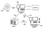
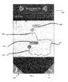
- FIG. 1is a schematic diagram of an overview of an exemplary embodiment of the system architecture of a wireless communication device according to the invention.
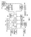
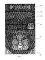
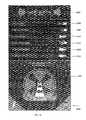
- FIG. 2is a schematic diagram of an overview of another exemplary embodiment of the system architecture of a wireless communication device including the device and cellular smartphone communications module.
- FIG. 3is a screen display of the software application than may be operated on the cellular smartphone.
- FIG. 4is a screen display of the software application than may be operated on the cellular smartphone.
- FIG. 5is a screen display of the software application than may be operated on the cellular smartphone.
- FIG. 6is a screen display of the software application than may be operated on the cellular smartphone.
- FIG. 7is a screen display of the software application than may be operated on the cellular smartphone.
- FIG. 8is a screen display of the software application than may be operated on the cellular smartphone.
- FIG. 9is a screen display of a software application reflecting emergency contacts data that may be entered by the user of the device according to an embodiment of the invention.
- FIG. 10is a screen display of the of a software application reflecting a screen that allows for contact data import according to an embodiment of the invention.
- FIG. 11is a screen display of the of a software application reflecting a screen that allows for contact data import according to an embodiment of the invention.
- FIG. 12is a screen display of the of a software application reflecting an options/Settings display screen according to an embodiment of the invention.
- Wireless communication primary device 100(which is all of FIG. 1 ) includes switch 110 , 112 and 114 .
- contact button 110may be used to initiate contact with a first address such as a primary emergency contact.
- Switch 112may be used to contact a second address such as secondary emergency contact.
- the third switch 114may be programmed to call an emergency number such as 911 that is used in most regions in the United States.
- the “primary device”, the “wireless communication primary device”, the “handheld beacon” and the “portable beacon”all refer to the same structure as schematically illustrated in FIG. 1 and in FIG. 2 at reference No. 250 .
- the contact buttonsmay have easily identifiable icons or symbols to facilitate easy dialing. In embodiments, these icons or symbols can be altered to correspond to the programming of the application that resides on the local cellular communication secondary device.
- primary device 100may also have communications buttons 116 , 118 .
- the communication buttonsmay include talk switch 116 and off switch 118 .
- Communications primary device 100is controlled by processor 130 which coordinates the electronic processes of wireless communications primary device 100 .
- Device 100may also include a power button 120 , for activating the primary device 100 .
- a volume switchers or dial 122is provided for increasing or decreasing the speaker volume of the device.
- Device 100also includes power supply 132 which is connected with rechargeable or other batteries.
- a charger 134is coupled with a power charging device such as a DC phone charger as known by those skilled in the art.
- Wireless communications primary device 100also has a memory 136 which, when used in conjunction with microprocessor 130 , is used to store on board software and/or firmware programs that implement the functionality of the wireless communications primary device 100 .
- Memory 136may also include storage for phone numbers as discussed above.
- Wireless communications primary device 100may also have power light 138 to indicate the status of the device and can provide information relating to the battery life.
- Wireless communications primary device 100may also have a radio frequency antenna 170 which as needed, may both receive and send radio frequency signals for wireless communication as is known by those skilled in the art. Signals received by a radio frequency antenna 170 are processed by cellular receiver 156 , amplified by audio amplifier 158 and, in turn, transmitted through speaker 160 such as an audible signal that may be heard by a user.
- the primary device 100includes a microphone 150 , which when coupled with the blue tooth radio transmitter 140 may wirelessly transmit a signal via radio frequency antenna 170 to the local communication secondary device.
- a indictor light and accelerometermay also be optionally included with device. In embodiment the device may initiate a signal based upon input to the controller from an accelerometer.
- the wireless communication primary device 100is described herein as being a “blue tooth” device, other short range wireless communication system may be advantageously used with the device.
- the portable primary device 100includes the components recited above mounted on a PC board and is designed to allow for the transfer of information to and from the secondary device and application designed for receiving the re-transmitting the information.
- Bluetooth 3.0 or 4.0 technologyis used to transfer data to and from the primary device 100 to a local secondary device which comprises a smartphone.
- Bluetooth 4.0refers to a standard is a wireless technology standard for exchanging data over short distances using short-wavelength UHF radio waves in the ISM band from 2.4 to 2.485 GHz.
- Bluetoothwas first standardized as IEEE 802.15.1 but the standard is no longer maintained.
- the Bluetooth Special Interest Grouppresently oversees the development of the specification, manages the qualification program, protects the trademarks.
- the communication protocolallows the application running on the secondary device to signal the primary device itself as well as provide audio communication via the speaker.
- the exterior of the deviceis constructed from a waterproof material to be able to connect during a storm or even after submergence in water.
- the primary devicecan also be triggered by proximity sensor or a rapid change in heart rate that would alert the Network.
- the primary devicealso includes the means to transfer signal to a network, send and receive real time audio transmissions, include a method of powering an LED to bring visual awareness as well as buttons that are used to trigger the Network via the application.
- Data that is transmitted from the primary devicemy include voice, preselected alert notifications, status information of the device, geographic position, and other data collected from input sensors.
- the input sensorsmay include accelerometers, and photo-detectors. Data transmission may be triggered by the activation of a switch by the user or be activated by other preselected input such as a signal from an accelerometer.
- embodiments of the portable primary deviceinclude a speaker, microphone, rechargeable battery, battery cable connection port, waterproof shell, LED light and input switches. It may be worn, strapped, clipped or mounted on user or object. After a switch or sequence of switches is activated, a signal to the local is transmitted to a network.
- the networkincludes but is not limited to, mobile phones, house phones, laptop, home or office computer, smartphone, satellite phone, wifi. Functions for the device are provided by the application, wherein a series of actions may be invoked upon reception of a signal from the primary portable device.
- the systemincludes the primary device 250 , and a secondary device 260 that is connect to a communications network 291 .
- the secondary communications deviceis a smartphone running an application that allows the primary device to activate the communication functions of the phone.
- the application in the cellphoneallows user input, including data relating to phone numbers, to be dialed in response to communication from the primary device.
- a communication protocolthat includes text messaging, and the replay of GPS data generated from either the primary or secondary device may be transmitted in response to predetermined signals from the primary device. If a voice connection has been made, the system will allow for voice communication from primary device, through the secondary device to a third party at a remote destination.
- FIG. 3is a screen display 301 of the welcome screen for the application that is run on the secondary communication device or smartphone.
- the smartphonehas a touch screen and that allows the functions discussed herein to be implemented.
- a userIn order to access the system, a user must enter a phone number at field 305 , an email address at field 307 and password at field 309 . This shows the logon and user information screen, using the user's phone number it gives a unique 2 way verifying process connecting to our server for tracking and database services allowing others to connect as well.
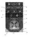
- FIG. 4is a screen display 401 main menu that includes menu selections my location 407 , that allows the user to activate GPS functions,
- a large beacon switch or button 420is located at the bottom for emergencies.
- the color of the activation buttonchanges from gray to blue when the device is connected to the primary device via Bluetooth communication, therefore reflecting that existence of the signal.
- the locationwill again respond by changing the color of the button to red and the application will initiate the emergency communication protocol.
- the screenincludes a ‘My Location’ feature 407 that shows the users current location used for tracking or identified whereabouts.
- a‘Distress Signal’ 408alerts users of the detection of a signal from the primary device to reflect the existence of an emergency situation.
- FIG. 4also illustrates other accessible features of the system including “Options” 410 that allows the user to access a screen to allow the control and adjustment of various functions on the device, as well as enabling and disabling various functions. See FIG. 12 .
- the “Upgrade” feature 420allows users to add extra functionality to the application.
- the “User Guide” function 425provides information regarding the features and functions of the system.
- the “Log out” function 430logs the user out of the application.
- the “Page Information” function 470 at bottom leftprovides information relating to the functionality of each button, switch or link on the screen.
- a “Battery” icon 490is provided that shows the amount of power that is remaining on the device.
- a shortcut to the easy set-up functionis provided at link 414 .
- an “Easy Setup” display screen 501is depicted.
- This device interfaceallows users to store their information and set up the device, including adding their respective contacts and provide input for the various other options available.
- the “My Information” field 512provides a link to a screen to accept data entry and allows the user to set up his personal information including setting up various features like his or her email address and phone carrier.
- the systemincludes a “Call Center Information” field 514 allows a user to access or make direct contact to a support call center operated by the service provider that can assist with the setting up a user account. The user may also use the call center for other technical support and ask questions pertaining to the service or implementing features of the system.
- the “text message setup” field 520allows users to create a custom message and title for their emergency text messages. See FIG. 8 .
- the “email message setup” field 520provides a link to a further screen to allow users to create a custom message and title for their emergency email messages.
- the “Emergency Contact Setup” field 515provides a link to another screen that allows users to add emergency contact information either from phones contacts or manually. (screen 5 a )
- FIG. 6is a screen display of a distress map 601 .
- the distress mapis displayed when the user gets a push notification, or text, or the silent beacon device alerts you, or the application is open when a contact is in an emergency. In real time it will show the current GPS location of the person in emergency so that they can be tracked and will transmit the information from the local communication device to a remote location via phone, text or email.
- the softwarewill drop a marker or pin such as 615 and 628 to identify where the person is and correlate the time with the location. The time of the drop is reflected at referenced number 615 and 628 . As the individual moves, a red line is drawn that tracks the pathway 612 and times are correlated at predetermined intervals.
- FIG. 7is the “My Information” screen display 701 .
- This screenallows for various information of the user to be stored and modified.
- One feature of this displayallows the user to import the information from a contact listing.
- a userenter his or her first and last name along with the users email address, mobile number, the users mobile phone carrier and other information can be entered at the users option.
- This screenalso provides for the functionality for setup of an email account to be used in distributing the emergency alert.
- the screenincludes an activation link to 707 allow importing data from contacts.
- the usermay also manually enter data in fields provided including first name 710 , last name 711 , email 712 , mobile phone 713 , carrier information 714 .
- the devicealso allows the user to set up an email account at link 720 .
- an Email Message set up display screen 801is displayed.
- This pageallows the user to setup a custom email message by activation of link 806 that will be transmitted to selected emergency contacts and used to advise the contacts that they are in an emergency situation.
- the text if the emailis displayed at field 808 .
- the usercan test the settings by activation on the smaller beacon icon that is reflected in the present embodiment by a green lighthouse icon in field 810 .
- FIG. 9is the “Emergency Contacts” display screen 901 .
- Screen 901is provides a list of emergency contacts 905 - 907 as well as fields to allow data entry to add additional contact 908 and 909 .
- a new screenis opened and the relevant data may be entered into the application.
- a usermay provide data relating to emergency contacts are added including data fields 904 - 909 .
- the usermay add manually contact information via a contacts list stored within the mobile smartphone device as well as edit them.
- FIG. 10is a Text Message display screen. This display allows the user to enter information to setup a custom text message letting their emergency contacts know they are in an emergency situation. The user may test the settings on the smaller beacon icon in green.
- FIG. 11is the Contact Setup display screen.
- the Contact Setup display screenallows users to add the fields of their emergency contacts. This setup can be manually inputted with data or the data may imported from the smartphone contact list.
- the data fields that may be populatedinclude (1) the user's first and last name (2) users email address (3) the user's mobile number (4) additional phone numbers and (5) the user's mobile phone carrier.
- FIG. 12is the “Options/Settings” display screen. This screen allows users to select communications options including Activating the Call Center call option”, 911, GPS Tracking enabling, Email Messaging, Text messaging, and device sounds.
- the application on the secondary communication devicemay access a local memory or can access memory stored on the network.
- This informationmay include but is not limited to names, email addresses, phone numbers, social media, and other contact information that identifies a person.
- the applicationutilizes functions within the network and can communicate with multiple recipients.
- Forms of communicationinclude but are not limited to, email, SMS messaging, push notifications, app alerts, video chat, voice calls, audio recordings and instant messaging.
- the usermay choose which forms of communication are to be used.
- the option of turning them on or offis within the application installed on the smartphone. Options include but are not limited to, texting from the secondary device of a user's location using a GPS function, texting to turn on tracking, email to show GPS location, email to alert that a user is in distress or needs assistance, contacting multiple people at once, contacting an emergency response center to communicate your current emergency.
- the applicationalso connects to servers which relay in real-time the location of the network triggered by the portable device.
- a call centercan automatically tracks a subscriber as well and can relay in real time to authorities or an emergency response center the whereabouts and condition of the user.
- the applicationis programmed to sequentially contact persons by phone on the list until a successful call is placed.
- the systemwill phone and text contacts on a predetermined list until a text or phone call is successfully completed or a text is acknowledged and a return text is transmitted.
- messages and phone callsare simultaneously transmitted upon the activation of the switch.
- the usercan select the option at the beacon to sequentially attempt to make contact or simultaneously make contact.
- a signalis transmitted back to the beacon that reflects a responsive text has been received.
- the text messagerequests that the recipient call the sender. The application will received the call and retransmit the voice signal to the beacon or first device.
Landscapes
- Engineering & Computer Science (AREA)
- Signal Processing (AREA)
- Computer Networks & Wireless Communication (AREA)
- General Physics & Mathematics (AREA)
- Business, Economics & Management (AREA)
- Emergency Management (AREA)
- Physics & Mathematics (AREA)
- Health & Medical Sciences (AREA)
- Public Health (AREA)
- Human Computer Interaction (AREA)
- Computer Security & Cryptography (AREA)
- Telephone Function (AREA)
- Alarm Systems (AREA)
Abstract
Description
Claims (18)
Priority Applications (2)
| Application Number | Priority Date | Filing Date | Title |
|---|---|---|---|
| US14/631,702US9756454B1 (en) | 2014-05-19 | 2015-02-25 | Portable wearable primary device which communciates data to secondary device that is in communication with multiple networks and related communication systems |
| US15/695,948US10460591B2 (en) | 2015-02-25 | 2017-09-05 | Portable wearable primary device which communicates data to secondary device that is in communication with multiple networks and related communication systems |
Applications Claiming Priority (2)
| Application Number | Priority Date | Filing Date | Title |
|---|---|---|---|
| US201462000178P | 2014-05-19 | 2014-05-19 | |
| US14/631,702US9756454B1 (en) | 2014-05-19 | 2015-02-25 | Portable wearable primary device which communciates data to secondary device that is in communication with multiple networks and related communication systems |
Related Child Applications (1)
| Application Number | Title | Priority Date | Filing Date |
|---|---|---|---|
| US15/695,948Continuation-In-PartUS10460591B2 (en) | 2015-02-25 | 2017-09-05 | Portable wearable primary device which communicates data to secondary device that is in communication with multiple networks and related communication systems |
Publications (1)
| Publication Number | Publication Date |
|---|---|
| US9756454B1true US9756454B1 (en) | 2017-09-05 |
Family
ID=59701553
Family Applications (1)
| Application Number | Title | Priority Date | Filing Date |
|---|---|---|---|
| US14/631,702Active - ReinstatedUS9756454B1 (en) | 2014-05-19 | 2015-02-25 | Portable wearable primary device which communciates data to secondary device that is in communication with multiple networks and related communication systems |
Country Status (1)
| Country | Link |
|---|---|
| US (1) | US9756454B1 (en) |
Cited By (2)
| Publication number | Priority date | Publication date | Assignee | Title |
|---|---|---|---|---|
| US9948330B2 (en)* | 2016-03-21 | 2018-04-17 | Chiun Mai Communication Systems, Inc. | Bluetooth transmitter |
| US11218861B2 (en)* | 2016-09-30 | 2022-01-04 | Kasiel Solutions Inc. | Low-power mobile telephony alert system |
Citations (61)
| Publication number | Priority date | Publication date | Assignee | Title |
|---|---|---|---|---|
| US4491970A (en) | 1982-12-30 | 1985-01-01 | Lifeline Systems, Inc. | Portable transmitter for emergency alarm system having watertight enclosure |
| US4647914A (en) | 1984-07-20 | 1987-03-03 | Mitsubishi Electric America, Inc. | Security apparatus and system |
| US4760593A (en) | 1985-05-16 | 1988-07-26 | Lifeline Systems, Inc. | Personal alarm system providing handsfree operation |
| US4998095A (en) | 1989-10-19 | 1991-03-05 | Specific Cruise Systems, Inc. | Emergency transmitter system |
| US5305370A (en) | 1991-09-04 | 1994-04-19 | Lloyd Kearns | Personal emergency response communications system |
| US5694452A (en) | 1996-03-14 | 1997-12-02 | Bertolet; Eric E. | Emergency telecommunication device |
| US5712619A (en) | 1996-04-18 | 1998-01-27 | Simkin; Alan C. | Global positioning system personal alarm |
| US5926103A (en) | 1994-05-16 | 1999-07-20 | Petite; T. David | Personalized security system |
| US6222484B1 (en)* | 1999-06-16 | 2001-04-24 | Ronald L. Seiple | Personal emergency location system |
| US6226510B1 (en) | 1998-03-19 | 2001-05-01 | American Secure Care, Llc | Emergency phone for automatically summoning multiple emergency response services |
| US6310539B1 (en) | 1997-11-20 | 2001-10-30 | X - 10 Ltd. | Panic button security alarm system |
| US6340928B1 (en) | 2000-06-22 | 2002-01-22 | Trw Inc. | Emergency assistance system using bluetooth technology |
| US6636732B1 (en) | 1998-03-19 | 2003-10-21 | Securealert, Inc. | Emergency phone with single-button activation |
| US6751484B1 (en)* | 1999-07-08 | 2004-06-15 | Telefonaktiebolaget Lm Ericsson | Portable communication apparatus having visual indicator means and a method of providing visual status indication thereof |
| US6807564B1 (en) | 2000-06-02 | 2004-10-19 | Bellsouth Intellectual Property Corporation | Panic button IP device |
| WO2005069676A1 (en) | 2004-01-16 | 2005-07-28 | First Aid Card Enterprises Ab | Apparatus and method for storing and distributing information in an emergency situation |
| US6927693B2 (en) | 2001-10-26 | 2005-08-09 | Koninklijke Philips Electronics, N.V. | Portable signal activator assembly |
| US7251471B2 (en) | 1998-03-19 | 2007-07-31 | Securealert, Inc. | Emergency phone with single button activation |
| US7265666B2 (en) | 2004-11-01 | 2007-09-04 | Sayo Isaac Daniel | Footwear covert alarm and locator apparatus |
| US20070265032A1 (en) | 2003-03-07 | 2007-11-15 | Alain Aisenberg | Group specific simplified cellular telephones |
| EP1924069A1 (en) | 2006-11-14 | 2008-05-21 | Promotion and Display Technology Limited | Telecommunication device for transmitting an emergency message |
| US7409044B2 (en) | 2000-07-21 | 2008-08-05 | Gemplus | Emergency call system and device |
| US20080214142A1 (en) | 2007-03-02 | 2008-09-04 | Michelle Stephanie Morin | Emergency Alerting System |
| US7486194B2 (en) | 2002-03-12 | 2009-02-03 | Sydney Devlin Stanners | Personal alarm system for obtaining assistance from remote recipients |
| US7548491B2 (en) | 2002-06-13 | 2009-06-16 | General Motors Corporation | Personalized key system for a mobile vehicle |
| WO2010030869A2 (en) | 2008-09-13 | 2010-03-18 | Michele Mccauley | Personal security device |
| US7750799B2 (en) | 2006-11-01 | 2010-07-06 | International Business Machines Corporation | Enabling a person in distress to covertly communicate with an emergency response center |
| USRE41845E1 (en) | 2004-09-30 | 2010-10-19 | Nevin Jenkins | Personal emergency communication system |
| US7844247B2 (en)* | 2006-01-25 | 2010-11-30 | International Business Machines Corporation | System for automatic wireless utilization of cellular telephone devices in an emergency by co-opting nearby cellular telephone devices |
| US20100303220A1 (en)* | 2009-05-27 | 2010-12-02 | Verizon Patent And Licensing Inc | Originating locator service |
| US7907931B2 (en)* | 2003-05-26 | 2011-03-15 | Securecom Technologies Limited | Portable communications device |
| US20120092157A1 (en) | 2005-10-16 | 2012-04-19 | Bao Tran | Personal emergency response (per) system |
| US8249547B1 (en) | 2011-06-16 | 2012-08-21 | Albert Fellner | Emergency alert device with mobile phone |
| US8279061B2 (en) | 2007-11-13 | 2012-10-02 | Elevate Technologies Pty Ltd. | Telemedicine application for remote monitoring, viewing and updating of patient records |
| US20120252401A1 (en) | 2008-04-16 | 2012-10-04 | Lmr Inventions, Llc | Systems and methods for communicating medical information |
| US8351895B2 (en) | 2009-09-04 | 2013-01-08 | Zomm, Llc | Wireless security device and method to place emergency calls |
| US20130078942A1 (en) | 2011-09-27 | 2013-03-28 | Rachel Dina Owens | Wearable networked alert unit and method for its use |
| US8423000B2 (en) | 2010-03-23 | 2013-04-16 | Anil Dhuna | Guardian system for a cognitively-impaired individual |
| US8461981B1 (en) | 1997-01-09 | 2013-06-11 | Donald Spector | Security sensor with remote communications capability |
| US8521125B2 (en) | 2011-05-20 | 2013-08-27 | Motorola Solutions, Inc. | Electronic communication systems and methods for real-time location and information coordination |
| US8548422B2 (en) | 2008-03-05 | 2013-10-01 | Nevin C. Jenkins | Versatile personal medical emergency communication system |
| US8588733B2 (en) | 2009-11-11 | 2013-11-19 | Lifestream Corporation | Wireless device emergency services connection and panic button, with crime and safety information system |
| US20140106677A1 (en)* | 2012-10-15 | 2014-04-17 | Qualcomm Incorporated | Wireless Area Network Enabled Mobile Device Accessory |
| US8742921B2 (en) | 2006-10-17 | 2014-06-03 | At&T Intellectual Property I, Lp | Methods, systems, devices and computer program products for transmitting medical information from mobile personal medical devices |
| US8766789B2 (en) | 2011-09-30 | 2014-07-01 | Cardiocom, Llc | First emergency response device |
| US20140184408A1 (en) | 2012-12-31 | 2014-07-03 | Cerner Innovation, Inc. | Alert management utilizing mobile devices |
| US8811934B2 (en) | 2007-09-14 | 2014-08-19 | Red Button Technologies Pty Ltd | Communications device, system and method |
| US8814792B2 (en) | 2010-07-27 | 2014-08-26 | Carefusion 303, Inc. | System and method for storing and forwarding data from a vital-signs monitor |
| US8823512B2 (en) | 1997-01-09 | 2014-09-02 | Donald Spector | Sensor with remote communications capability |
| US8866606B1 (en) | 2013-07-16 | 2014-10-21 | Rockwilli RMR LLC | Systems and methods for automated personal emergency responses |
| US8872623B2 (en) | 2011-01-13 | 2014-10-28 | Cherie Ann SIMPSON | Voice alarm |
| US8890656B2 (en) | 2010-08-31 | 2014-11-18 | pomdevices, LLC | Mobile panic button for health monitoring system |
| US8894577B2 (en) | 1999-11-05 | 2014-11-25 | Elite Care Technologies, Inc. | System and method for medical information monitoring and processing |
| US20140365390A1 (en) | 2013-06-07 | 2014-12-11 | Emergency University, Inc. | Method and apparatus for emergency response notification |
| US20150077211A1 (en) | 2013-09-17 | 2015-03-19 | Lsis Co., Ltd. | Circuit breaker with a magnet fixing means |
| US9035744B2 (en) | 2009-10-01 | 2015-05-19 | Blackberry Limited | Method and apparatus for monitoring and controlling a medical device using a wireless mobile communication device |
| US20150145674A1 (en) | 2013-08-28 | 2015-05-28 | Jan Rydfors | Caretaking Communication Bracelet |
| US9087442B2 (en) | 2001-01-02 | 2015-07-21 | Global Life-Line, Inc. | Panic device with local alarm and distal signaling capability |
| US20150235539A1 (en) | 2014-02-18 | 2015-08-20 | Etón Corporation | Multi-functional device having at least the ability to detect the presence of a substance |
| US20150269825A1 (en) | 2014-03-20 | 2015-09-24 | Bao Tran | Patient monitoring appliance |
| US20150269827A1 (en) | 2014-03-20 | 2015-09-24 | Better Alerts, LLC | System and method for sending medical emergency alerts |
- 2015
- 2015-02-25USUS14/631,702patent/US9756454B1/enactiveActive - Reinstated
Patent Citations (61)
| Publication number | Priority date | Publication date | Assignee | Title |
|---|---|---|---|---|
| US4491970A (en) | 1982-12-30 | 1985-01-01 | Lifeline Systems, Inc. | Portable transmitter for emergency alarm system having watertight enclosure |
| US4647914A (en) | 1984-07-20 | 1987-03-03 | Mitsubishi Electric America, Inc. | Security apparatus and system |
| US4760593A (en) | 1985-05-16 | 1988-07-26 | Lifeline Systems, Inc. | Personal alarm system providing handsfree operation |
| US4998095A (en) | 1989-10-19 | 1991-03-05 | Specific Cruise Systems, Inc. | Emergency transmitter system |
| US5305370A (en) | 1991-09-04 | 1994-04-19 | Lloyd Kearns | Personal emergency response communications system |
| US5926103A (en) | 1994-05-16 | 1999-07-20 | Petite; T. David | Personalized security system |
| US5694452A (en) | 1996-03-14 | 1997-12-02 | Bertolet; Eric E. | Emergency telecommunication device |
| US5712619A (en) | 1996-04-18 | 1998-01-27 | Simkin; Alan C. | Global positioning system personal alarm |
| US8823512B2 (en) | 1997-01-09 | 2014-09-02 | Donald Spector | Sensor with remote communications capability |
| US8461981B1 (en) | 1997-01-09 | 2013-06-11 | Donald Spector | Security sensor with remote communications capability |
| US6310539B1 (en) | 1997-11-20 | 2001-10-30 | X - 10 Ltd. | Panic button security alarm system |
| US6636732B1 (en) | 1998-03-19 | 2003-10-21 | Securealert, Inc. | Emergency phone with single-button activation |
| US7251471B2 (en) | 1998-03-19 | 2007-07-31 | Securealert, Inc. | Emergency phone with single button activation |
| US6226510B1 (en) | 1998-03-19 | 2001-05-01 | American Secure Care, Llc | Emergency phone for automatically summoning multiple emergency response services |
| US6222484B1 (en)* | 1999-06-16 | 2001-04-24 | Ronald L. Seiple | Personal emergency location system |
| US6751484B1 (en)* | 1999-07-08 | 2004-06-15 | Telefonaktiebolaget Lm Ericsson | Portable communication apparatus having visual indicator means and a method of providing visual status indication thereof |
| US8894577B2 (en) | 1999-11-05 | 2014-11-25 | Elite Care Technologies, Inc. | System and method for medical information monitoring and processing |
| US6807564B1 (en) | 2000-06-02 | 2004-10-19 | Bellsouth Intellectual Property Corporation | Panic button IP device |
| US6340928B1 (en) | 2000-06-22 | 2002-01-22 | Trw Inc. | Emergency assistance system using bluetooth technology |
| US7409044B2 (en) | 2000-07-21 | 2008-08-05 | Gemplus | Emergency call system and device |
| US9087442B2 (en) | 2001-01-02 | 2015-07-21 | Global Life-Line, Inc. | Panic device with local alarm and distal signaling capability |
| US6927693B2 (en) | 2001-10-26 | 2005-08-09 | Koninklijke Philips Electronics, N.V. | Portable signal activator assembly |
| US7486194B2 (en) | 2002-03-12 | 2009-02-03 | Sydney Devlin Stanners | Personal alarm system for obtaining assistance from remote recipients |
| US7548491B2 (en) | 2002-06-13 | 2009-06-16 | General Motors Corporation | Personalized key system for a mobile vehicle |
| US20070265032A1 (en) | 2003-03-07 | 2007-11-15 | Alain Aisenberg | Group specific simplified cellular telephones |
| US7907931B2 (en)* | 2003-05-26 | 2011-03-15 | Securecom Technologies Limited | Portable communications device |
| WO2005069676A1 (en) | 2004-01-16 | 2005-07-28 | First Aid Card Enterprises Ab | Apparatus and method for storing and distributing information in an emergency situation |
| USRE41845E1 (en) | 2004-09-30 | 2010-10-19 | Nevin Jenkins | Personal emergency communication system |
| US7265666B2 (en) | 2004-11-01 | 2007-09-04 | Sayo Isaac Daniel | Footwear covert alarm and locator apparatus |
| US20120092157A1 (en) | 2005-10-16 | 2012-04-19 | Bao Tran | Personal emergency response (per) system |
| US7844247B2 (en)* | 2006-01-25 | 2010-11-30 | International Business Machines Corporation | System for automatic wireless utilization of cellular telephone devices in an emergency by co-opting nearby cellular telephone devices |
| US8742921B2 (en) | 2006-10-17 | 2014-06-03 | At&T Intellectual Property I, Lp | Methods, systems, devices and computer program products for transmitting medical information from mobile personal medical devices |
| US7750799B2 (en) | 2006-11-01 | 2010-07-06 | International Business Machines Corporation | Enabling a person in distress to covertly communicate with an emergency response center |
| EP1924069A1 (en) | 2006-11-14 | 2008-05-21 | Promotion and Display Technology Limited | Telecommunication device for transmitting an emergency message |
| US20080214142A1 (en) | 2007-03-02 | 2008-09-04 | Michelle Stephanie Morin | Emergency Alerting System |
| US8811934B2 (en) | 2007-09-14 | 2014-08-19 | Red Button Technologies Pty Ltd | Communications device, system and method |
| US8279061B2 (en) | 2007-11-13 | 2012-10-02 | Elevate Technologies Pty Ltd. | Telemedicine application for remote monitoring, viewing and updating of patient records |
| US8548422B2 (en) | 2008-03-05 | 2013-10-01 | Nevin C. Jenkins | Versatile personal medical emergency communication system |
| US20120252401A1 (en) | 2008-04-16 | 2012-10-04 | Lmr Inventions, Llc | Systems and methods for communicating medical information |
| WO2010030869A2 (en) | 2008-09-13 | 2010-03-18 | Michele Mccauley | Personal security device |
| US20100303220A1 (en)* | 2009-05-27 | 2010-12-02 | Verizon Patent And Licensing Inc | Originating locator service |
| US8351895B2 (en) | 2009-09-04 | 2013-01-08 | Zomm, Llc | Wireless security device and method to place emergency calls |
| US9035744B2 (en) | 2009-10-01 | 2015-05-19 | Blackberry Limited | Method and apparatus for monitoring and controlling a medical device using a wireless mobile communication device |
| US8588733B2 (en) | 2009-11-11 | 2013-11-19 | Lifestream Corporation | Wireless device emergency services connection and panic button, with crime and safety information system |
| US8423000B2 (en) | 2010-03-23 | 2013-04-16 | Anil Dhuna | Guardian system for a cognitively-impaired individual |
| US8814792B2 (en) | 2010-07-27 | 2014-08-26 | Carefusion 303, Inc. | System and method for storing and forwarding data from a vital-signs monitor |
| US8890656B2 (en) | 2010-08-31 | 2014-11-18 | pomdevices, LLC | Mobile panic button for health monitoring system |
| US8872623B2 (en) | 2011-01-13 | 2014-10-28 | Cherie Ann SIMPSON | Voice alarm |
| US8521125B2 (en) | 2011-05-20 | 2013-08-27 | Motorola Solutions, Inc. | Electronic communication systems and methods for real-time location and information coordination |
| US8249547B1 (en) | 2011-06-16 | 2012-08-21 | Albert Fellner | Emergency alert device with mobile phone |
| US20130078942A1 (en) | 2011-09-27 | 2013-03-28 | Rachel Dina Owens | Wearable networked alert unit and method for its use |
| US8766789B2 (en) | 2011-09-30 | 2014-07-01 | Cardiocom, Llc | First emergency response device |
| US20140106677A1 (en)* | 2012-10-15 | 2014-04-17 | Qualcomm Incorporated | Wireless Area Network Enabled Mobile Device Accessory |
| US20140184408A1 (en) | 2012-12-31 | 2014-07-03 | Cerner Innovation, Inc. | Alert management utilizing mobile devices |
| US20140365390A1 (en) | 2013-06-07 | 2014-12-11 | Emergency University, Inc. | Method and apparatus for emergency response notification |
| US8866606B1 (en) | 2013-07-16 | 2014-10-21 | Rockwilli RMR LLC | Systems and methods for automated personal emergency responses |
| US20150145674A1 (en) | 2013-08-28 | 2015-05-28 | Jan Rydfors | Caretaking Communication Bracelet |
| US20150077211A1 (en) | 2013-09-17 | 2015-03-19 | Lsis Co., Ltd. | Circuit breaker with a magnet fixing means |
| US20150235539A1 (en) | 2014-02-18 | 2015-08-20 | Etón Corporation | Multi-functional device having at least the ability to detect the presence of a substance |
| US20150269825A1 (en) | 2014-03-20 | 2015-09-24 | Bao Tran | Patient monitoring appliance |
| US20150269827A1 (en) | 2014-03-20 | 2015-09-24 | Better Alerts, LLC | System and method for sending medical emergency alerts |
Cited By (3)
| Publication number | Priority date | Publication date | Assignee | Title |
|---|---|---|---|---|
| US9948330B2 (en)* | 2016-03-21 | 2018-04-17 | Chiun Mai Communication Systems, Inc. | Bluetooth transmitter |
| US11218861B2 (en)* | 2016-09-30 | 2022-01-04 | Kasiel Solutions Inc. | Low-power mobile telephony alert system |
| US11736925B2 (en) | 2016-09-30 | 2023-08-22 | Kasiel Solutions Inc. | Low-power mobile telephony alert system |
Similar Documents
| Publication | Publication Date | Title |
|---|---|---|
| US11528354B2 (en) | Personal emergency triggering, notification and communication for smartwatches | |
| US20110230161A1 (en) | Smartphone emergency alarm | |
| US9025735B2 (en) | Emergency communications system | |
| KR100827709B1 (en) | Emergency call abuse prevention system and method using mobile communication network | |
| US20100330952A1 (en) | Personal safety device, system and process | |
| US20140031000A1 (en) | Method for emergency signaling via mobile telecommunications device | |
| US20080214142A1 (en) | Emergency Alerting System | |
| US20140308915A1 (en) | Notification and Tracking System for Mobile Devices | |
| US9177464B2 (en) | Method and system for untethered two-way voice communication for an alarm system | |
| US20120003956A1 (en) | Real time sound/image capture and distibution to end recipient | |
| US20070293186A1 (en) | Systems and Methods for a Personal Safety Device | |
| US10460591B2 (en) | Portable wearable primary device which communicates data to secondary device that is in communication with multiple networks and related communication systems | |
| CN106658386B (en) | Cloud service Bluetooth emergency rescue system | |
| US20140177812A1 (en) | Urgent and emergency notification and communication system | |
| US10446016B2 (en) | Advanced mobile emergency communication system | |
| WO2014087157A1 (en) | Communication device | |
| US20240346912A1 (en) | Personal security alert device and monitory system | |
| US9756454B1 (en) | Portable wearable primary device which communciates data to secondary device that is in communication with multiple networks and related communication systems | |
| WO2005036487A2 (en) | Personal security system | |
| WO2006135119A1 (en) | Emergency call system and control method thereof | |
| US20210127243A1 (en) | Portable Wearable Primary Device which Communicates Data to Secondary Device that is in Communication with Multiple Networks and Related Communication Systems | |
| US10587408B2 (en) | Digital assistant water mark | |
| US8571185B1 (en) | Multi-site personal emergency telephone system and method | |
| US20210228162A1 (en) | Medical alert device | |
| EP2706517A2 (en) | Mobile alarm device and system |
Legal Events
| Date | Code | Title | Description |
|---|---|---|---|
| AS | Assignment | Owner name:SILENT BEACON INCORPORATED, MARYLAND Free format text:ASSIGNMENT OF ASSIGNORS INTEREST;ASSIGNOR:KELLEY, KENNY;REEL/FRAME:036734/0060 Effective date:20151002 | |
| AS | Assignment | Owner name:SILENT BEACON LLC, MARYLAND Free format text:ASSIGNMENT OF ASSIGNORS INTEREST;ASSIGNOR:SILENT BEACON INCORPORATED;REEL/FRAME:037016/0891 Effective date:20151104 | |
| STCF | Information on status: patent grant | Free format text:PATENTED CASE | |
| FEPP | Fee payment procedure | Free format text:MAINTENANCE FEE REMINDER MAILED (ORIGINAL EVENT CODE: REM.); ENTITY STATUS OF PATENT OWNER: SMALL ENTITY | |
| LAPS | Lapse for failure to pay maintenance fees | Free format text:PATENT EXPIRED FOR FAILURE TO PAY MAINTENANCE FEES (ORIGINAL EVENT CODE: EXP.); ENTITY STATUS OF PATENT OWNER: SMALL ENTITY | |
| STCH | Information on status: patent discontinuation | Free format text:PATENT EXPIRED DUE TO NONPAYMENT OF MAINTENANCE FEES UNDER 37 CFR 1.362 | |
| FP | Lapsed due to failure to pay maintenance fee | Effective date:20210905 | |
| PRDP | Patent reinstated due to the acceptance of a late maintenance fee | Effective date:20220713 | |
| FEPP | Fee payment procedure | Free format text:PETITION RELATED TO MAINTENANCE FEES FILED (ORIGINAL EVENT CODE: PMFP); ENTITY STATUS OF PATENT OWNER: SMALL ENTITY Free format text:PETITION RELATED TO MAINTENANCE FEES GRANTED (ORIGINAL EVENT CODE: PMFG); ENTITY STATUS OF PATENT OWNER: SMALL ENTITY Free format text:SURCHARGE, PETITION TO ACCEPT PYMT AFTER EXP, UNINTENTIONAL. (ORIGINAL EVENT CODE: M2558); ENTITY STATUS OF PATENT OWNER: SMALL ENTITY | |
| MAFP | Maintenance fee payment | Free format text:PAYMENT OF MAINTENANCE FEE, 4TH YR, SMALL ENTITY (ORIGINAL EVENT CODE: M2551); ENTITY STATUS OF PATENT OWNER: SMALL ENTITY Year of fee payment:4 | |
| STCF | Information on status: patent grant | Free format text:PATENTED CASE | |
| FEPP | Fee payment procedure | Free format text:MAINTENANCE FEE REMINDER MAILED (ORIGINAL EVENT CODE: REM.); ENTITY STATUS OF PATENT OWNER: SMALL ENTITY | |
| FEPP | Fee payment procedure | Free format text:7.5 YR SURCHARGE - LATE PMT W/IN 6 MO, SMALL ENTITY (ORIGINAL EVENT CODE: M2555); ENTITY STATUS OF PATENT OWNER: SMALL ENTITY | |
| MAFP | Maintenance fee payment | Free format text:PAYMENT OF MAINTENANCE FEE, 8TH YR, SMALL ENTITY (ORIGINAL EVENT CODE: M2552); ENTITY STATUS OF PATENT OWNER: SMALL ENTITY Year of fee payment:8 |