US9756288B2 - Tiering and manipulation of peer's heads in a telepresence system - Google Patents
Tiering and manipulation of peer's heads in a telepresence systemDownload PDFInfo
- Publication number
- US9756288B2 US9756288B2US14/767,336US201314767336AUS9756288B2US 9756288 B2US9756288 B2US 9756288B2US 201314767336 AUS201314767336 AUS 201314767336AUS 9756288 B2US9756288 B2US 9756288B2
- Authority
- US
- United States
- Prior art keywords
- participant
- image
- images
- processed
- participants
- Prior art date
- Legal status (The legal status is an assumption and is not a legal conclusion. Google has not performed a legal analysis and makes no representation as to the accuracy of the status listed.)
- Active
Links
Images


Classifications
- H—ELECTRICITY
- H04—ELECTRIC COMMUNICATION TECHNIQUE
- H04N—PICTORIAL COMMUNICATION, e.g. TELEVISION
- H04N7/00—Television systems
- H04N7/14—Systems for two-way working
- H04N7/15—Conference systems
- G06K9/0061—
- G06K9/52—
- G—PHYSICS
- G06—COMPUTING OR CALCULATING; COUNTING
- G06T—IMAGE DATA PROCESSING OR GENERATION, IN GENERAL
- G06T11/00—2D [Two Dimensional] image generation
- G06T11/60—Editing figures and text; Combining figures or text
- G—PHYSICS
- G06—COMPUTING OR CALCULATING; COUNTING
- G06T—IMAGE DATA PROCESSING OR GENERATION, IN GENERAL
- G06T7/00—Image analysis
- G06T7/10—Segmentation; Edge detection
- G—PHYSICS
- G06—COMPUTING OR CALCULATING; COUNTING
- G06T—IMAGE DATA PROCESSING OR GENERATION, IN GENERAL
- G06T7/00—Image analysis
- G06T7/10—Segmentation; Edge detection
- G06T7/194—Segmentation; Edge detection involving foreground-background segmentation
- G—PHYSICS
- G06—COMPUTING OR CALCULATING; COUNTING
- G06T—IMAGE DATA PROCESSING OR GENERATION, IN GENERAL
- G06T7/00—Image analysis
- G06T7/60—Analysis of geometric attributes
- G—PHYSICS
- G06—COMPUTING OR CALCULATING; COUNTING
- G06V—IMAGE OR VIDEO RECOGNITION OR UNDERSTANDING
- G06V40/00—Recognition of biometric, human-related or animal-related patterns in image or video data
- G06V40/10—Human or animal bodies, e.g. vehicle occupants or pedestrians; Body parts, e.g. hands
- G06V40/18—Eye characteristics, e.g. of the iris
- G06V40/193—Preprocessing; Feature extraction
- H—ELECTRICITY
- H04—ELECTRIC COMMUNICATION TECHNIQUE
- H04N—PICTORIAL COMMUNICATION, e.g. TELEVISION
- H04N21/00—Selective content distribution, e.g. interactive television or video on demand [VOD]
- H04N21/40—Client devices specifically adapted for the reception of or interaction with content, e.g. set-top-box [STB]; Operations thereof
- H04N21/41—Structure of client; Structure of client peripherals
- H04N21/422—Input-only peripherals, i.e. input devices connected to specially adapted client devices, e.g. global positioning system [GPS]
- H04N21/4223—Cameras
- H—ELECTRICITY
- H04—ELECTRIC COMMUNICATION TECHNIQUE
- H04N—PICTORIAL COMMUNICATION, e.g. TELEVISION
- H04N21/00—Selective content distribution, e.g. interactive television or video on demand [VOD]
- H04N21/40—Client devices specifically adapted for the reception of or interaction with content, e.g. set-top-box [STB]; Operations thereof
- H04N21/47—End-user applications
- H04N21/478—Supplemental services, e.g. displaying phone caller identification, shopping application
- H04N21/4788—Supplemental services, e.g. displaying phone caller identification, shopping application communicating with other users, e.g. chatting
- H—ELECTRICITY
- H04—ELECTRIC COMMUNICATION TECHNIQUE
- H04N—PICTORIAL COMMUNICATION, e.g. TELEVISION
- H04N7/00—Television systems
- H04N7/14—Systems for two-way working
- H04N7/141—Systems for two-way working between two video terminals, e.g. videophone
- H04N7/142—Constructional details of the terminal equipment, e.g. arrangements of the camera and the display
- G—PHYSICS
- G06—COMPUTING OR CALCULATING; COUNTING
- G06T—IMAGE DATA PROCESSING OR GENERATION, IN GENERAL
- G06T2207/00—Indexing scheme for image analysis or image enhancement
- G06T2207/20—Special algorithmic details
- G06T2207/20212—Image combination
- G06T2207/20221—Image fusion; Image merging
- G—PHYSICS
- G06—COMPUTING OR CALCULATING; COUNTING
- G06T—IMAGE DATA PROCESSING OR GENERATION, IN GENERAL
- G06T2207/00—Indexing scheme for image analysis or image enhancement
- G06T2207/30—Subject of image; Context of image processing
- G06T2207/30196—Human being; Person
Definitions
- video conference systemstypically include one or more individual monitors, each displaying images from cameras at one or more remote locations.
- a video conference monitorwill typically display the image capture by each remote camera in a separate window. Displaying the individual camera images in separate windows leads to unattractive tiling of the display screen, and results in large amounts of wasted screen space allocated to the gaps between people (or windows) and lots of background images. Because of the wasted space, the video conference participants in such a display appear much smaller than life-size. For this reason, typical video conference systems employ a nearly room-sized screen or a collection of large monitors in order to provide a life-sized display of the participants.
- video conferencinghas become available for consumer use in the form of a telepresence system that allows subscribers of network-supplied content, such as cable television subscribers, to view shared content among themselves while simultaneously exchanging images of each other.
- network-supplied contentsuch as cable television subscribers
- the term “participants”will identify such network system subscribers that participate in a telepresence system session.
- the same problem of displaying individual video images on a single monitor incurred by commercial video conference systemsalso plagues consumer telepresence systems.
- the solutions employed to address this problem in commercial video conference systems, such as large screen monitorsare impractical for use in a consumer telepresence environment.
- a method for displaying at a local station images of participants at remote stationscommences by establishing at the local station the images of the participants at the remote stations processed to isolate such remote participant in the image from image background
- the processed images of the participants at the remote stationsare merged to generate an output image in which a first processed participant image appears to partially overlay another second processed participant image.
- the output imageundergoes display on a display device at the local station.
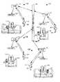
- FIG. 1depicts a block diagram of telepresence system having four stations for practicing the display technique of the present principles
- FIG. 2depicts four situations, each corresponding to the operation of a separate one of the four telepresence stations of FIG. 1 ;
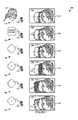
- FIG. 3depicts a sequence of images associated with a first exemplary process for separating the head of a participant from the background image and establishing metadata for each participant image;
- FIG. 4shows a first set of images of remote participants composited into a single display
- FIG. 5shows a second set of images of remote participants composited into a single display
- FIG. 6depicts in flow chart form the steps of a method for compositing the images of remote participant into a single display
- FIG. 7depicts a sequence of images showing manipulation of the order of composing of the remote participant images
- FIG. 8depicts, in flow chart form, the steps of a method for manipulating the order of compositing of the remote participant images
- FIG. 9depicts a block schematic diagram of a set-top box for controlling activity at a station in the telepresence system of FIG. 1 , the set-top box being one exemplary embodiment suitable for the present invention.
- FIG. 10depicts a sequence of images associated with replacing the video feed from a remote participant when that remote participant exits the field of view of the remote telepresence camera.
- FIG. 1depicts a block schematic diagram of a telepresence system 100 having four stations 110 , 120 , 130 , and 140 , each deployed at a particular location, for example a residential or commercial premises.
- Each of the stations 110 , 120 , 130 , and 140serves a separate one of participants 113 , 123 , 133 , and 143 , respectively, (sometimes referred to as users, viewers, or audience members).
- each of participants 113 , 123 , 133 , and 143watches shared content (i.e., content viewed substantially simultaneously by all the participants, e.g., a football game being broadcast) on a separate one of the shared content monitor 112 , 122 , 132 , and 142 , respectively, while situated on one of couches or chairs 114 , 124 , 134 , and 144 , respectively.
- shared contenti.e., content viewed substantially simultaneously by all the participants, e.g., a football game being broadcast
- Each of participants 113 , 123 , 133 , and 143uses a separate one of remote controls 115 , 125 , 135 , and 145 , respectively, to operate a corresponding one of set-top boxes (STBs) 111 , 121 , 131 , and 141 , respectively.
- STBsset-top boxes
- each of the set-top boxes 111 , 121 , 131 , and 141at the stations 110 , 120 , 130 , and 140 , respectively, controls the display of shared content displayed on a corresponding one of the shared content monitors 112 , 122 , 132 , and 142 , respectively.
- Each STBhas a connection to a communication channel 101 typically operated by a network service operator, such as a cable television operator or telecommunications company.
- the communications channel 101could exist as part of a proprietary network maintained by the network service operator.
- the communications channelcould comprise a broadband connection to the Internet, as offered by an Internet Service Provider (ISP).
- ISPInternet Service Provider
- the communication channel 101enables the STBs 111 , 121 , 131 , and 141 to exchange audio, video and/or information with each other, with or without intermediation by a server (not shown), as well as to obtain content from one or more content sources (not shown).
- Each of the STBs 111 , 121 , 131 , and 141receives incoming video from a corresponding one of the telepresence cameras 117 , 127 , 137 , and 147 , respectively, situated at the stations 110 , 120 , 130 , and 140 , respectively, for capturing the image of a corresponding one of the participants 113 , 123 , 133 , and 143 , respectively at each station. Further, each of the STBs 111 , 121 , 131 , and 141 receives video from the other STBs of the corresponding remote participants for display on a corresponding one of telepresence monitor 116 , 126 , 136 , and 146 , respectively.
- the term “local participant”refers to the participant whose image undergoes capture by the telepresence camera at a given station for display on the telepresence monitor at one or more distant stations.
- the term “remote participant”refers to a participant associated with another station (i.e., a “remote station”) whose image undergoes display on the telepresence monitor of the local participant.
- each of the participants 113 , 123 , 133 , and 143will sit directly in front of a corresponding one of the shared content monitor 112 , 122 , 132 , and 142 , respectively.
- each of the participants 113 , 123 , 133 , and 143has a particular orientation or facing 118 , 128 , 138 , and 148 , respectively, with respect to his/her corresponding shared content monitor.
- the telepresence cameras 117 , 127 , 137 , and 147 , respectively, and telepresence monitors 116 , 126 , 136 and 146 , respectively,lie to one the side of the participant at that station.
- each of the participants 113 , 123 , 133 and 143has a particular one of facings 119 , 129 , 139 , and 149 , respectively.
- the telepresence monitor and telepresence camera pairlie to the left of the shared content monitor, as at the station 130 .
- the telepresence monitor/telepresence camera pairlie to the right of the shared content monitor.
- the STBscan exchange information with other about the facing of their respective participants relative to their corresponding telepresence monitor/telepresence camera pair.
- the STBs 111 , 121 , 131 and 141 of FIG. 1can interact by assuming a predetermined facing (e.g., providing and handling telepresence video streams as if they originated from telepresence cameras lying on a particular side of the participant, e.g., to a participant's right when the participant faces the shared content monitor).
- FIG. 2depicts an aggregate situation 200 comprised of four individual situations 210 , 220 , 230 , and 240 , each representative of the operation of a separate one of the four telepresence stations 110 , 120 , 130 , and 140 .
- shared contentplays out in substantial synchronization on a separate one of the shared content monitors 112 , 122 , 132 , and 142 , respectively.
- the participants 113 , 133 , and 143 at the stations 110 , 130 and 140 , respectively,are currently facing their corresponding shared content monitor, while the participant 123 at station 120 faces his/her corresponding telepresence monitor 126 and co-located telepresence camera 127 .
- the telepresence cameras 117 , 127 , 137 , and 147capture the images 217 , 227 , 237 , and 247 , respectively, of the participants 113 , 123 , 133 and 143 , respectively.
- such imagesbear the designation “telepresence images.”
- the telepresence camera images 217 , 237 , and 247will depict the corresponding participants in profile.
- the situation 220 associated with the operation of the station 120depicts the participant 123 facing his/her telepresence camera/telepresence monitor pair 127 / 126 .
- the telepresence camera image 227depicts the participant 123 directly facing his/her telepresence camera so as to appear substantially straight on, rather than in profile.
- Each of the telepresence monitors 116 , 126 , 136 , and 146displays a corresponding one of the composite images 216 , 226 , 236 , and 246 , respectively.
- Each composite image displayed on the corresponding telepresence monitor of a local participantincludes the telepresence images of the remote participants.
- FIG. 1which includes the four stations 110 , 120 , 130 , and 140
- each local telepresence monitor depicted in the situation 200 of FIG. 2displays the images of the three remote telepresence cameras.
- the telepresence monitor 116displays the composite image 216 comprised of at least a portion of the images 227 , 237 , and 247 captured by the telepresence cameras 127 , 137 , and 147 .
- the composite image 216 displayed by telepresence monitor 116 at the station 110does not include the telepresence image 217 from camera 117 , because that telepresence image is local with respect to that telepresence monitor.
- the telepresence images 217 , 227 , 237 , and 247may or may not require horizontal flipping before undergoing display on their corresponding remote telepresence monitors.
- the need to horizontally flip the telepresence imagedepends on the relative orientation (i.e., facing) of the participant to the telepresence camera at that station. In other words, whether the telepresence image undergoes flipping depends on whether the participant needs to turn right or left to face his/her telepresence camera straight on.
- the telepresence image 227requires horizontal flipping prior to display on the remote telepresence monitors 116 and 146 , because the facing 129 at station 120 is rightward, as are facings 119 and 149 at stations 110 and 140 .
- the telepresence image 227does not require horizontal flipping prior to display on the telepresence monitor on 136 because the facing 129 at the station 120 is rightward and facing 139 at station 130 is the opposite (leftward).
- each of the corresponding participants 113 , 123 and 143respectively will turn in the same direction (e.g., rightward with respect to the shared content monitor, as seen in FIG. 1 ) to face his/her respective telepresence camera.
- the participants 123 and 133respectively must turn in opposite directions (e.g., right and left, respectively, with respect to their shared content monitors, as seen in FIG.
- the stations 120 and 130have opposite facings. This resembles a physical situation in which two individuals are sitting on a couch watching TV: The person on the left must turn rightward to face the person on the right, while the person on the right must turn leftward. Because a telepresence monitor can be placed to either side of the shared content monitor, the telepresence facings are not constrained by that physical situation. Instead, the physical situation is simulated, if needed, by providing a mirror image of a remote participant whenever the telepresence camera placements do not conform to the analogous physical situation.
- the station 130has a facing opposite to all of the other stations. For this reason, the telepresence image 237 originating from the station 130 need not undergo horizontal flipping when displayed on the remote telepresence monitors 116 , 126 , and 146 , as seen in the composite images 216 , 226 , and 246 of FIG. 2 .
- each of the telepresence images 217 , 227 , 237 , and 247requires processing to isolate the participant's head from the background in that telepresence image.
- a number of image processing techniques exist for separating an object from a static backgroundas surveyed by Cheung, et al, in their article Robust techniques for background subtraction in urban traffic video, Proceedings of Electronic Imaging: Visual Communications and Image Processing, 2004, WA, SPIE. (5308):881-892.
- FIG. 3depicts a sequence of images associated with a first exemplary process 300 for separating the head of a participant from the background image and establishing metadata for each participant's image. Step 301 in FIG.
- step 3constitutes the first step in an overall process of obtaining one or more images from a telepresence camera, for example, telepresence camera 117 of FIG. 1 .
- the processalso produces an image 310 having a background characterized by static background objects (e.g., object 311 ) represented by pixels having substantially the same value for the preponderance of observations when monitored over a period of time.
- step 301includes the sub-steps of identifying and recording a value for each pixel so that background image 310 substantially models the static background with high confidence.
- a participantwill receive a prompt to evacuate the field of view of telepresence camera 117 and a single image of the unoccupied room taken by the corresponding telepresence camera can serve as the background image 310 .
- More sophisticated algorithmscan dynamically accumulate pixels for the background image 310 by monitoring which value or range or collection of values represents an individual pixel most of the time, usually over an interval longer than a person will likely to sit still (e.g., several minutes or hours).
- Other algorithmscan build and track object models, for example placing an object (e.g., a book) into a scene and quickly observing the object as constituting something static rather than a participant (e.g., by color or scale), and thereby quickly classifying the object as a background object and thus a part of background image 310 .
- capturing the backgroundoccurs over time to enable modeling of the background as pixels that do not change, except slowly, other than when a participant appears in the frame, or nearby, or the lighting changes suddenly (e.g., when a participant turns on a lamp or opens a shade for example.)
- the background image 310can undergo time averaging to reduce noise, and can undergo recording to provide multiple background models, for example under different lighting conditions.
- modeling of the backgroundcan occur by noting the pixels whose color value and luminance value only change slowly over time (e.g., a minute), if at all.
- the pixelseventually return to their prior value, e.g., as when the person has passed by.
- the background image isolation processwould include a further step (not shown) to correlate the current orientation of the camera 117 with the appropriate portion of the background model represented by the background image 310 , where the whole of the background model could be larger than represented by background image 310 .
- participant isolation step 302there are two separate, parallel examples of participant isolation step 302 , illustrated as two columns of images.
- the resulting difference image 320comprises a substantially empty field 321 where only a slight residual signal remains, e.g., residual signal 322 , corresponding to static background object 311 .
- residual signal 322e.g. 322
- the current video imagelooks substantially like the image 310 and that when background image 310 gets subtracted from a substantially similar image, only a slight residual value remains as shown. For a static background, such a residual value appears most pronounced near the high-contrast edges in background image 310 .
- the image subtraction processsubtracts the value of a pixel in the background model from the value of the corresponding pixel in the current image. Only the magnitude of the result warrants consideration so if the pixel has a current value only slightly more or less than its value in the background, then the subtraction produces a result that might be zero, or a small positive or negative value near zero. Since only the magnitude warrants consideration, the result is zero or a small, but positive, value.
- the subtractionoccurs separately for each of the primary colors (i.e., red, green, blue). In some embodiments, a difference in one primary color (e.g., the green) for a pixel will undergo weighting more heavily than a difference for the other colors (e.g., red and blue) due to different camera sensitivities.
- FIG. 3the images selected for illustration make the content most clearly visible, as depicted by black details on white background.
- a subtraction processwould produce a substantially black frame (because most values are at or near zero), with slightly non-black details. However, this would result in an image difficult to present with any clarity.
- the images in FIG. 3other than image 310 , appear inverted, showing black details within a substantially white field for purposes of clarity.
- the corresponding difference image 323 between the current video image and the background image 310results in the region 326 being substantially non-empty, that is, region 326 comprises many pixels representing a difference-magnitude of values substantially greater than zero.
- This region 326corresponds substantially to the region in the current image that represents participant 113 , while the background area 324 remains substantially empty where the difference from the static background objects is substantially zero, thus leaving only a residual signal, e.g., residual object signal 325 .
- the difference results 320 and 323undergo image processing to refine the current candidate participant region 326 to provide a better estimate of where the participant's image resides (if present at all) in the current image.
- the results of a such sequence of operationappears in images 330 , 340 , 350 , and 360 for a current video image where participant 113 does not appear, and in images 333 , 343 , 353 , and 363 for a current video image where participant 113 does appear.
- This exemplary sequence of image processing operationsincludes thresholding, dilation, erosion, and dilation again, though more, fewer, or different operations could occur using the same or different operating parameters.
- the thresholding operationsserve to whiten any pixels in the corresponding difference image ( 320 , 323 ) having a difference magnitude less than a predetermined valued (i.e., where the current video pixel's value substantially equals the same pixel's value in the background image 310 ). These operations also set the rest of the pixels to black (i.e., where a current video pixel substantially differs from the background). This generally eliminates most of the remnant signal 322 / 325 corresponding to background objects 311 . As a result, only a small residual signal 332 / 335 remains within the otherwise empty background fields 331 / 334 , and the candidate participant region 336 become more definite.
- the dilation processexpands marked (black) regions and conversely, reduces empty (white) regions.
- the degree of this expansionas measured in pixels, generally remains predetermined, but could dynamically vary based on effectiveness in iterative attempts to refine the candidate region. Described another way, each unmarked (white) pixel lying within a predetermined distance of any marked (black) pixel, becomes marked (black). In this example, the predetermined dilation value equals two pixels.
- the background (white) regions 341 / 344become slightly reduced, while the residual signals 342 / 345 (which are black) become slightly enlarged.
- the candidate region 346(also black) becomes slightly enlarged, but gaps and hairlines previously riddling the candidate region 336 substantially disappear.
- the erosion operationconstitutes the reverse of dilation. Erosion unmarks (removes) each marked (black) pixel lying within a predetermined distance from any empty (white) pixels, causing such previously black pixels to become white.
- the erosion operationhas the effect of deleting black features smaller than about twice the predetermined size (in pixels), turning them white. Erosion also has the effect of removing stray black pixels or narrow black lines which may still remain near high-contrast edges that may have locally increased the likely magnitude of residual difference value, e.g. along the edge of a shelf or doorway.
- the predetermined erosion valueequals three pixels, selected to be greater than the two pixel valued used in the first dilation.
- the background (white) regions 351 / 354appear substantially empty because of elimination of the residual signals 342 / 345 at 352 / 355 . All that remains is the candidate region 356 .
- the candidate region 356may become smaller than appropriate.
- this second dilation operationcauses no change to empty background 361 , because there were no black pixels to dilate.
- the candidate region 366becomes slightly larger than the region 356 and should substantially correspond to the pixels presenting the image of participant 113 in the current image generated by the telepresence camera 117 .
- step 303upon detecting the presence of a participant (as might be determined by having region 366 comprising at least a predetermined number of pixels), the current image undergoes cropping and scaling and the background is made transparent.
- a simple analysis of candidate region 366can identify the top, left, right, and bottom extents ( 367 T, 367 L, 367 R, 367 B), for example as determined by the left and rightmost columns and top and bottom-most rows having at least a predetermined number of marked pixels.
- Such extentscan serve to determine a cropping of the current image suitable to isolate the participant image 373 within the current image.
- Pixels in the isolated participant image 373can serve to force pixels in participant image 373 to become transparent.
- the pixelsrepresent the participant region 376 (and thus show the participant), or they belong to the transparent background 374 .
- the candidate region 366appears too small, i.e., comprises too-few columns or too-few rows when compared to a set of predetermined limits, as might be the case if an animal entered the field of view, then the STB could ignore the candidate participant region 366 and treat the participant as absent, as with the empty image 360 .
- facial recognition software executed the STB 111can identify the participant's eye region 377 , and such software can determine the normalized half-head height 378 in accordance with the distance between the horizontal midline of eye region 377 and the top of the participant's head (corresponding to extent 367 T). As long as the participant 113 remains in approximately the same position (e.g., sitting in the same seat on the couch 114 ), then the half-head height value 378 will remain substantially the same, but could undergo averaging over multiple measurements to minimize the influence of noise present in a single measurement.
- the STB 111could obtain an estimate of half-head height 378 from half the distance between top and bottom extents 3671 and 367 B.
- the STB 111could make use of a previous value for the half-head height obtained during a prior session.
- the value for half-head height 378suddenly undergoes updating (for example, when an estimate no longer becomes necessary because the STB 111 has obtained an actual measurement of the half-height 378 or when a noisy initial measurement becomes refined by subsequent measurements)
- any display process using the half-head height valueshould transition to the new value gradually, to avoid sudden changes in the display.
- the half-head height valueserves to establish the scale factor of the participant image 373 when used in conjunction with other participant images for the head scaling and composition process 400 , as shown in FIG. 4 .
- Parameters other than half-head height valuesuch as eye spacing, or head width (e.g., as determined by the median width row in candidate region 366 ) could serve as well in place of the half-head height value.
- the systemcan make use of the participants' actual head heights and match the image to a template for that participant.
- the normalization step 410serves to produce normalized participant head images 411 , 413 , and 414 , wherein each corresponding remote telepresence station receives the normalized head image of each local participant.
- Each normalized head imagerepresents approximately the same normalized head height 405 .
- head image 411would result from resealing of a participant image (e.g., isolated participant image 373 of participant 113 ) by the scale factor of five hundred divided by double the half-head height 378 (in pixels).
- the scale factorwould equal 500/(2*100) or 2.5, so scaling up the participant image 373 by a factor of 250% could yield a corresponding normalized head image (like image 411 ).
- the scale factorcould have a value less than 100%, corresponding to a normalized head imaged obtained by scaling down the participant image by a corresponding amount.
- other methods or mechanismscan serve to isolate the participant image 373 .
- telepresence camera 117comprised a stereoscopic camera that produced a stereoscopic image pair
- an analysis of disparities between the left- and right-eye imagescould determine the position of the participant and distinguish the participant from the background objects 311 , since in a stereoscopic image pair, the pixels corresponding to background objects 311 will have a more positive disparity than pixels corresponding to nearer objects, such as the participant.
- a 3D scannersuch as the Kinect sensor for the XBOX 360 game system, both available from Microsoft Corp., Redmond, Wash., could serve to differentiate between the participant and the background.
- recognition of the participantcould occur by fitting a 3D participant model to the 3D scan data (or disparity maps derived from a stereoscopic camera), where the participant model adequately matches the 3D scan data.
- a separate camera(not shown) collocated with the telepresence camera 117 , but sensitive to the far infrared (far-IR), could serve to identify the participant 113 by heat signature.
- Employing a near-IR emitter (not shown) in conjunction with a near-IR cameracould provide additional image information useful for differentiating between the participant and any background objects.
- the steps of the method of in FIG. 3could serve to detect multiple participants within the field of view of the telepresence camera 117 .
- the multiple participant imagesproduce distinguishable candidate regions (not shown, but like region 366 )
- the local STB 111could generate multiple local participant images 373 for separate transmission to the remote telepresence stations.
- the local STB 111could composite such images locally and treat the composite image as a single participant image using techniques similar to those discussed herein.
- the candidate regionwould yield a multi-participant image used in lieu of the participant image 373 .
- head scaling and composition process 400(comprising steps 410 , 420 , 440 , and 450 ) is shown as concerning station 120 and STB 121 , thus the scaling of the remote participant heads 411 , 413 , and 414 occurring during the normalization step 410 takes place at each of the STBs 111 , 131 , and 141 , all of which exist remotely relative to STB 121 .
- the STB 121receives each of images of the normalized participant heads 411 , 413 , 414 via the communication channel 101 .
- each image of the normalized remote heads 411 , 413 , and 414undergoes further resealing to fit on the telepresence display 126 of FIG. 1 .
- Each of the remote participantsis assigned to a different graphic layer, such that the participant assigned to the foremost layer does not get hidden by any other participant, but the participants assigned to deeper layers may get partially hidden by those participants on the higher (shallower) layers.
- the foremost participant image 431gets scaled to 100% of the height 421 .
- the participant image 434 on the next deeper layergets scaled to 90% of the height 421 , i.e., to height 424
- participant image 433 on the third layergets scaled to 80% of the height 421 , i.e., to height 423 .
- the images of the remote participantscan appear to be in perspective, hence the designation of step 420 as the “perspecting” step,
- the STB 121applies a horizontal translation to each of the perspected remote participant images 431 , 433 , and 434 .
- each of the remote participant imagesmay require and/or may have already undergone a horizontal flip, as discussed above and taught in the cited co-pending applications, herein incorporated by reference.
- the remote participant imagesshould undergo display facing left.
- the translation step 440proceeds by identifying the leftmost column 443 of the least forward image 433 and then providing a translation into a position within image 226 , near the left edge.
- the leftmost column 444 of the next least-forward image 434gets translated to appear within the image 226 rightward of the left edge of the least forward image 433 by a predetermined horizontal distance 451 , where the predetermined horizontal distance 451 may have a value less than the width of the perspected remote participant image 433 .
- the leftmost column 441 of the foremost image 431undergoes a horizontal translation to appear within the image 226 rightward of the left edge of image 434 by the predetermined horizontal distance 452 , where distances 451 and 452 approximately equal each other (or, alternatively, relate to each other by a scale factor, e.g., with distance 451 being 90% of the distance 452 ).
- FIG. 5depicts a similar head scaling and composition process 500 , made with respect to station 140 and STB 141 , wherein the remote participant head images 511 , 512 , and 513 undergo normalization during step 510 to a height 505 (much as during the normalization step 410 of FIG. 4 ) at their respective STBs.
- the participant head images 511 , 512 , and 513appear remote with respect to station 140 , and undergo transmission via the communication channel 101 to STB 141 .
- the perspecting step 520much as during perspecting step 420 of FIG.
- the remote participant head images 511 , 512 , 513undergo scaling, for example to produce: (a) the image 531 scaled to 80% of the full height 523 , i.e., to height 521 , (b) the image 532 scaled to 90% of the full height 523 , i.e., to height 522 , and (c) the image 533 scaled to 100%, i.e., full height 523 .
- the leftmost columns 541 , 542 , and 543 corresponding to perspected remote participant images 531 , 532 , 533undergo identification and translation into positions within the image 246 .
- the STB 131 at the sending station 130both of FIG. 1
- the STB 131 at the sending station 130will tag the remote participant image 532 as facing the telepresence camera.
- Such a tagwould result from detection by the STB 131 of an eye region (e.g., like detected eye region 377 ) in the corresponding participant image.
- the spacing between the leftmost edges of the consecutive images to either side of image 532 during translationgets increased.
- the combined participant image isolation and normalization process 600begins upon execution of step 601 during which, a local telepresence camera (e.g., telepresence camera 117 ) having a field of view of a portion of the corresponding station (e.g., station 110 ), supplies an image of that field of view to the local STB (e.g., STB 111 ).
- the local STBcommunicates via the communication channel 101 with one or more remote STBs (e.g., STBs 121 , 131 , and 141 ).
- modeling of the backgroundoccurs (e.g., as during step 301 , above) to yield a background image 310 which may undergo storage in the settings database 613 or elsewhere (not shown).
- the current image from the local telepresence cameraundergoes analysis with respect to the background model (e.g., image 310 ) to identify that portion (if any) representing the local participant (e.g., 113 ) similar to step 302 discussed above with respect to FIG. 3 .
- the current imagegets cropped to the region corresponding to the local participant 113 , with any included pixels representing the background being made transparent.
- step 605if no region represents the local participant (e.g., 360 ), or if the region appears smaller than a predetermined size, then during step 611 , the local STB (e.g., 111 ) sends message to the remote stations that no participant appears at that station (e.g., 110 ).
- the local STBe.g., 111
- the STBe.g., 111
- the STBchecks if it can find an eye region. If so, then during step 607 , the local STB uses the location of the eye region (e.g., 377 ) within the participant region (e.g., 366 ) to determine the scale of the participant image, which gets enlarged, reduced, or left unchanged, as appropriate, to match normalized scale 405 .
- the STBfinds no eye region, then during step 608 , the STB applies a default scale factor so the participant image matches the normalized scale 405 , where the default scale factor can constitute one of (a) a predetermined value, (b) a scale factor identified during step 607 for a previous image, or (c) the normalized scale height 405 divided by the full height of the candidate participant region (e.g., the magnitude of the difference between 367 T and 367 B).
- the local STBe.g., 111
- a normalized participant imagee.g., 411
- the processends at step 610 , but repeats for each subsequent telepresence video frame, where subsequent iterations may begin at step 603 , or in a modified step 602 (e.g., during which the background image 310 undergoes dynamic updating).
- a portion of the image normalizationmay be performed by the remote stations, upon receipt.
- participant detection, eye detection, and head-height estimationsmight be performed by the local STB, with the results sent with an un-normalized image to each remote STBs where, upon receipt, the remote STBs can perform the appropriate scaling. This might be advantageous if the images were being scaled up, as smaller images might be more economical to send.
- still more of the process 600might be performed by the remote STBs.
- the remote participant head imagesget “stacked” in each of the telepresence screen images 216 , 226 , 236 , and 246 in an arbitrary order, here as if the stations were in positioned about a circle with consecutive positions arranged counterclockwise according to a hypothetical order in which the stations 110 , 120 , 130 , and 140 joined the telepresence session (and as shown in FIG. 1 ).
- the local participant 113 at station 110will see the remote participant images in the following order, the image 227 appears furthest away, the image 237 appears in the middle and the image and 247 appears foremost.
- the second participant 123 joining the telepresence sessionobserves the remote image 237 furthest away, the remote image 247 in the middle and 217 foremost, and so on.
- Such an initial placementwould give each participant approximately equal exposure or “proximity” to others upon joining.
- each telepresence screenis arbitrary. For example, a different ordering could have the image 217 of the first participant 113 appearing foremost on each of the remote telepresence screens 126 , 136 , 146 (in FIG. 2 this order exists only for the telepresence monitor 126 at station 120 ).
- the second joining participanthere, 123
- the last joining participanthere, 143
- FIG. 7illustrates a remote participant image order manipulation process 700 that the local participant 113 can control using his/her remote control 115 .
- the processescommences step 710 during which the current order of remote participant images, represented by the composite telepresence image 711 , undergoes display on the local telepresence monitor 116 .
- the local participantcan reorder the images starting at step 720 by actuating a “reorder friends” button 722 on his or her remote control 115 .
- the local STB 111 of FIG. 1highlights an arbitrary one of the remote participant images, in this case remote participant image 723 , as seen in the composite telepresence image 721 of FIG. 7 .
- the local participant 113can select a desired image for repositioning by actuating the arrow button 732 on the remote control 115 during step 730 .
- the STB 111will update the display to highlight the next remote participant image, now image 733 , as shown in the telepresence image 731 of FIG. 7 .
- the local participant 113will designate the currently highlighted remote participant image 733 as the desired participant image for re-positioning during step 740 by actuating the button 742 on the remote control 115 .
- STB 111will display the middle remote participant image 743 of FIG. 7 as being selected, as shown in telepresence image 741 .
- the press of the left-arrow button 752 by the local participant 113 during 750will cause the selected head image 743 to switch places with head image 744 , which initially appeared to the left and further away than selected head image 743 .
- the selected head image 753now appears leftmost and furthest, and head image 754 now appears in the selected head image's previous position. Note that perspective scaling has been updated for each of head images 753 and 754 from their prior values for head images 743 and 744 , based on their new ordering.
- step 770the local participant will press the select button 742 again, this time to unselect the head image 733 , as shown in the telepresence image 771 . Thereafter, the remote participant image order manipulation process 700 concludes.
- FIG. 8depicts a flowchart for participant image order manipulation process 800 , as one example, for implementing the image re-ordering process 700 of FIG. 7 .
- the order manipulation process 800begins at step 801 , typically following actuation by the participant 113 of FIG. 1 of the “reorder friends” button 722 on remote the control 115 .
- the local STB 111 of FIG. 1will highlight a first remote participant image, e.g., image 723 , during step 802 .
- the settings database 813will store the various states (such as “highlighted”, “selected”, or “unhighlighted and unselected”) and positions (e.g., “foremost”, “next to foremost”, . . .
- the local STBwill make use the states as recorded in the settings database 813 to direct the composition and rendering of the individual remote participant images.
- the settings database 813will also record whether an individual remote participant image requires a horizontal flip.
- the STBexpects an input from the remote control 115 . If the participant 113 presses an arrow key (e.g., the arrow key 732 or 752 ), then during step 804 , the highlight moves from one remote participant head image to another, according to the direction of the arrow. This may recur upon each actuation of the arrow key until the local STB 111 detects actuation of the select key 742 during step 805 of FIG. 8 , at which point, during step 806 , the currently highlighted remote participant image (e.g., image 733 ) becomes the selected remote participant image (e.g., image 743 ).
- an arrow keye.g., the arrow key 732 or 752
- the STBwill expect another input from the remote control 115 . If the participant 113 actuates an arrow key again (e.g., the arrow key 732 or 752 ), then during step 808 , the STB changes the position of the selected remote participant image in accordance with the arrow direction, for example, moving the participant head image moved further away (e.g., for arrow key 752 ).
- the state (including horizontal position, perspective scaling, and priority) of other non-selected remote participant imagese.g., image 744
- may undergo modificatione.g., as in image 754 to produce a composite telepresence image (e.g.
- step 810undergoes execution, whereupon the STB 111 sets the selected remote participant image to an unselected and unhighlighted state (e.g., image 773 ).
- the manipulation process 800concludes at step 811 .
- FIG. 9shows a block schematic diagram of an implementation of the STB 111 of FIG. 1 .
- the telepresence camera 117provides an output signal 901 embodying the local participant image 217 (which may contain background information).
- a set of one or more outbound video buffers 910 in the STB 111store the images embodied in the camera output signal 901 .
- the term “outbound” when used in connection with the video buffers 910reflects that the images stored in such buffers ultimately undergo transmission to the remote telepresence stations.
- An outbound video controller 911under the control of a master controller 923 , processes the images stored in video buffers 910 . Such processing can include performing the background modeling that occurs during the step 301 of FIG. 3 , local participant isolation, as occurs during step 302 of FIG.
- the controller 923instructs an outbound video controller 911 to transfer a portion of the local participant image (e.g. the image 373 ) to an encoder 912 which generates an outbound participant image 917 .
- the encoder 912can also provide ancillary information about the outbound participant image 917 .
- Such informationcan indicate whether the image 917 contains a participant image (e.g., as known from the image 363 ) or not (e.g., as known from the image 360 ), and whether or not the STB detected the eye region 377 , and if so, then where the eye region is (e.g., the value for half-head height 378 ).
- the remote STBscan use such additional information when compositing the outbound participant image with images of other participants such as during steps 450 and 550 of corresponding head scaling and composition processes 400 and 500 , respectively, of FIGS. 4 and 5 , respectively.
- the outbound video controller 911may use other information from the settings database 913 , to determine whether or not the local participant image needs horizontal flipping.
- the STBs 111 , 121 , 131 , and 141adhere to a convention wherein the STBs exchange participant images with a facing as if the sending STB's participant image originated from a telepresence camera lying to the right of the corresponding shared content monitor. Since telepresence camera 117 actually does lie to the right of the shared content monitor 112 at station 110 of FIG. 1 , the image from that telepresence camera requires no flipping prior to transmission as the outbound local participant image 917 with respect to local participant image 217 .
- a communication interface 914 within the STB 111 of FIG. 9relays the outbound participant image 917 to the communication channel 101 for transmission to each of remote STBs 121 , 131 , and 141 at corresponding stations 120 , 130 , and 140 , respectively.
- the STB 111receives corresponding inbound remote participant images 927 , 937 , and 947 (of which, 937 was horizontally flipped with respect to original image 237 by remote STB 131 ) via the communication channel 101 , at a communication interface 914 , which passes the received images to a decoder 915 .
- the decoder 915parses out each of the inbound remote participant images 927 , 937 , and 947 (or processed versions thereof, e.g., if any of the images had undergone encoding), to a set of inbound video buffers 918 A, 918 B and 918 C, respectively. f the decoder 915 detects information provided with or about the images 927 , 937 , and 947 , the decoder will send such information 916 to the settings database 913 . Examples of such information may include messages as to whether a remote STB detected the presence of a participant during handling of the remote participant image, or the remote STB detected the eye region 377 , and in some embodiments, where that STB detected the eye region. In some embodiments, the scale factor appropriate to the participant image may be provided (e.g., in lieu of the participant image having been scaled prior to sending).
- an inbound video controller 919can determine where to position each inbound participant head image and in what order, as well as whether to flip such images horizontally (as would be the case for all three in the present example of the station 110 and STB 111 ), and with what spacing.
- the inbound video controller 919places remote the participant image data from each of the inbound video buffers 918 A, 918 B and 918 C into the appropriate position in a video output buffer 920 , which generates an inbound telepresence video signal 921 carrying the composite telepresence image 216 to telepresence monitor 116 for display.
- an STBmay periodically record an image of each remote participant, in case a remote participant leaves the field of view of his/her corresponding telepresence camera. This recorded image would provide a placeholder image for the remote participant, until he or she returns.
- FIG. 10illustrates such a placeholder substitution process 1000 .
- the process 1000commences upon execution of step 1010 during which the local STB (e.g., STB 121 ) analyzes the local participant difference image 1011 to determine whether the extent of the local participant image remains within its frame.
- the local STBe.g., STB 121
- the outbound participant image 1013undergoes transmission to the remote STBs (e.g., 111 ) for inclusion in the composite telepresence image (e.g., 1012 ) on the remote telepresence screen (e.g., 116 , where outbound participant image 1013 appears horizontally flipped).
- the remote STBse.g., 111
- the composite telepresence imagee.g., 1012
- the remote telepresence screene.g., 116
- the local STBdetects whether the local participant difference image 1021 exhibits a substantial “opposite edge violation”, where the local participant image has undergone cropping at both the top and the bottom by the field of view (whereas, during step 1010 , the difference image 1011 exhibits cropping of the participant image only at the bottom).
- the local STB 121automatically detects this condition, causing the local STB to interrupt the real-time video feed of the local participant image and replace it with the most recently stored local participant image, e.g., image 1013 , which does not exhibit the top and bottom cropping of difference image 1021 .
- the remote telepresence screen 116will display the composite telepresence image 1022 with the still image 1023 derived from the earlier participant image 1013 .
- the remote participant images displayed in the composite image 1022other than participant image 1023 , remain as live, real-time video throughout this process.
- the STBcan make use of criteria in addition to, or in place of the opposite edge violation to trigger the freeze frame of the outbound participant image. For example, the STB can make use of a frame count, where the opposite edge violation must continue for at least a predetermined amount of time (e.g., one second) before a stored participant image is used. Alternatively, the STB could determine that the size of the top edge violation must equal or exceed a certain width (e.g., a raised arm might not be wide enough, nor a peak of hair, but having the head image cropped to the forehead would be sufficient).
- a predetermined amount of timee.g., one second
- the STBcould determine that the size of the top edge violation must equal or exceed a certain width (e.g., a raised arm might not be wide enough, nor a peak of hair, but having the head image cropped to the forehead would be sufficient).
- the STBcould derive the width from, or scale the width to, the size of the participant image determined before the opposite edge violation. For example, the STB could record the minimum width found for the fully processed candidate region (e.g., region 366 ) below the midpoint of the candidate region, and use that value as a proxy for the “participant neck width”. Thus, until the cropping of a participant's head results in a truncated flat area at least as wide as the participant's neck, the STB would maintain the real-time participant image, albeit with the top of the head flattened by the cropping due to the participant's position in the field of view.
- the STBcould maintain the real-time participant image, albeit with the top of the head flattened by the cropping due to the participant's position in the field of view.
- the local STB 121will generate a candidate region in difference image 1031 substantially unlike a participant silhouette. Whether due to a detection of this condition, or due to the freeze frame state of step 1020 being sustained for more than a predetermined amount of time (e.g., five seconds), the freeze-frame participant image 1033 in telepresence composite image 1032 undergoes modification to indicate the freeze-frame state. For example, the local STB 121 could make the freeze-frame image 1033 partially transparent by, making the stored participant image being sent to remote STBs appear as a ghost.
- a predetermined amount of timee.g., five seconds
- local STB 121could dim the freeze-frame image 1033 being sent, for example, by graphically applying a translucent gray smoke to reduce the contrast relative to the unprocessed freeze-frame image 1023 . This would leave the identity of the remote participant recognizable, but clearly indicate that the participant may not be telepresent, that is, may not be within view of or earshot of his telepresence station. By making this situation visibly clear, a participant will have a greater understanding why another participant seems unresponsive.
- the partial transparency or graying of remote participant image 1033may be imposed by the receiving remote STBs (e.g., 111 ) before display in composite image 1032 .
- the difference image 1041yields no candidate region as the local participant resides wholly outside the field of view.
- the STB 121could specifically detect this condition and use this information instead of other criteria for triggering a freeze-frame of an earlier-captured local participant image.
- criteriasuch as the detection of the lack presence of the participant, whether or not used in conjunction with a timer, can serve to trigger a “participant has left the vicinity” chime or other audible indication to remote participants to warn that a participant has left the vicinity of his or her corresponding telepresence station.
- the processed freeze-frame image of the absent participant 1043exists as a still image the other participant images (e.g., 1044 ) remain as live, real-time video.
- the candidate region in difference image 1051no longer remains empty, which, when detected, can serve as a criterion to trigger a “participant has returned within earshot” chime or other audible indication.
- the composite telepresence image 1052still shows the processed freeze-frame 1053 .
- the processing of freeze-frames 1033 and 1053may differ from the processing of freeze-frame 1043 (where the participant does not appear at all).
- the STB 121could lower the contrast of the processed freeze-frames 1033 and 1053 , but when the participant appears absent, the STB 121 could make the processed freeze-frame 1043 further fractionally transparent.
- the degree of transparencymay increase the longer the participant remains absent (up to some maximum transparency). In some embodiments, after a prolonged absence (e.g., 10 minutes) such as during step 1040 , the receiving STB 111 could drop the absent participant from the telepresence session entirely (not shown).
- the difference image 1061produces a qualified candidate area (e.g., as at area 363 in FIG. 3 ) without opposite edge violations.
- the STB 121will replace the freeze-frame participant image with a live, real-time outbound participant image 1063 (shown as horizontally flipped in composite telepresence image 1062 ).
- the STBcould provide an audible chime or brief highlight (shown around participant head image 1063 ).
- the detection of a participant becoming absentcould trigger the shared content playing on monitors 112 , 122 , 132 , and 142 to automatically and synchronously pause. In this way, no participant needs to intervene manually, e.g., by using remote controls 115 , 125 , 135 , and 145 , to stop the content play out.
- the shared contentmay automatically resume play out in synchronism at all of the stations 110 , 120 , 130 , and 140 once the absent participant returns to within earshot (e.g., step 1050 ), or the absent participant has resumed a qualified position (e.g., step 1060 ), that is, the participant has taken his or her seat.
- impatient participantsmay not wait for the participant to reappear. Any impatient participant could use his or her corresponding remote control to command the system 100 to continue play out of the shared content. Alternatively, the participant departing during step 1030 may command the system 100 to continue in his or her absence (e.g., by using his or her remote control to command the system to keep playing).
- the departing participantmight signal the telepresence system to keep playing out content with a hand gesture.
- a departing participantcould signal his or her STB by a hand with index finger pointed at the shared content monitor moving in a clockwise orbit perpendicular to the pointed finger, a gesture used typically used in filmmaking and in some sports activities to indicate a “keep rolling” command or a “keep the game clock running” command.
- Such a gesturecan signal the local STB to continue content play out even if the STB has detected departure of the local participant.
- the STB 121will typically remain in this state until expiration of a predetermined interval.
- the STBwill disregard the “keep rolling” gesture. If, however, if the local participant does leave within this interval, then the state initiated by the keep rolling gesture prevents the shared content from pausing.
- placeholder substitution process 1000detects a departing or absent participant (e.g., steps 1020 - 1040 )
- the videomay remain live if fewer than all of the local participants have departed.
- the shared contentmay automatically pause when one or more of the multiple local participants depart, and automatically resume once all of the multiple local participants have returned and taken their seat. In this way, for example an hour into a movie, everyone can agree to take a break, with the system automatically pausing until all the participants (including the multiple local participants at a particular station) have returned.
- policiesfall within the consideration of this technique: For example, if well into a shared content presentation an additional local participant joins with another local participant, and within a few minutes decides that this shared content does not interest him or her, then departure of the recently added participant might not trigger an automatic pause of the shared content.
- Such a policymight include parameters such as how much viewing a of a piece of shared content by an individual participant constitutes an investment by that participant into the presentation, such that upon that participant's departure being detected a pausing of the shared content becomes warranted. That is, the investment of four telepresence participants at the onset of a shared content program is equal.
- a fifth participantjoins as an additional participant a one of the locations.
- the additional participantcould be considered as having an investment equal to the others, at which point a departure by the additional participant would induce an automatic pause by the shared content telepresence system 100 .
- the foregoingdescribes a technique for adjusting the display of participants in a telepresence system in which participants can share content along with the sharing of images of themselves.
Landscapes
- Engineering & Computer Science (AREA)
- Multimedia (AREA)
- Physics & Mathematics (AREA)
- Signal Processing (AREA)
- General Physics & Mathematics (AREA)
- Theoretical Computer Science (AREA)
- Computer Vision & Pattern Recognition (AREA)
- General Engineering & Computer Science (AREA)
- Geometry (AREA)
- Health & Medical Sciences (AREA)
- General Health & Medical Sciences (AREA)
- Ophthalmology & Optometry (AREA)
- Human Computer Interaction (AREA)
- Two-Way Televisions, Distribution Of Moving Picture Or The Like (AREA)
Abstract
Description
Claims (22)
Applications Claiming Priority (1)
| Application Number | Priority Date | Filing Date | Title |
|---|---|---|---|
| PCT/US2013/035981WO2014168616A1 (en) | 2013-04-10 | 2013-04-10 | Tiering and manipulation of peer's heads in a telepresence system |
Publications (2)
| Publication Number | Publication Date |
|---|---|
| US20160150186A1 US20160150186A1 (en) | 2016-05-26 |
| US9756288B2true US9756288B2 (en) | 2017-09-05 |
Family
ID=48183009
Family Applications (1)
| Application Number | Title | Priority Date | Filing Date |
|---|---|---|---|
| US14/767,336ActiveUS9756288B2 (en) | 2013-04-10 | 2013-04-10 | Tiering and manipulation of peer's heads in a telepresence system |
Country Status (2)
| Country | Link |
|---|---|
| US (1) | US9756288B2 (en) |
| WO (1) | WO2014168616A1 (en) |
Cited By (3)
| Publication number | Priority date | Publication date | Assignee | Title |
|---|---|---|---|---|
| US10140728B1 (en)* | 2016-08-11 | 2018-11-27 | Citrix Systems, Inc. | Encoder with image filtering and associated methods |
| US11363088B1 (en)* | 2020-11-27 | 2022-06-14 | Zoom Video Communications, Inc. | Methods and apparatus for receiving virtual relocation during a network conference |
| US11601482B2 (en) | 2020-11-27 | 2023-03-07 | Zoom Video Communications, Inc. | Methods and apparatus for performing virtual relocation during a network conference |
Families Citing this family (17)
| Publication number | Priority date | Publication date | Assignee | Title |
|---|---|---|---|---|
| US8502856B2 (en) | 2010-04-07 | 2013-08-06 | Apple Inc. | In conference display adjustments |
| CN104160708B (en) | 2012-03-09 | 2018-12-11 | 汤姆逊许可公司 | Distributed control of synchronized content |
| WO2014204459A1 (en) | 2013-06-20 | 2014-12-24 | Thomson Licensing | System and method to assist synchronization of distributed play out of control |
| US10600169B2 (en)* | 2015-03-26 | 2020-03-24 | Sony Corporation | Image processing system and image processing method |
| US10636154B2 (en)* | 2015-04-01 | 2020-04-28 | Owl Labs, Inc. | Scaling sub-scenes within a wide angle scene by setting a width of a sub-scene video signal |
| US10372298B2 (en) | 2017-09-29 | 2019-08-06 | Apple Inc. | User interface for multi-user communication session |
| CN112214275B (en)* | 2018-05-07 | 2021-10-29 | 苹果公司 | Multi-participant real-time communication user interface |
| US11513667B2 (en) | 2020-05-11 | 2022-11-29 | Apple Inc. | User interface for audio message |
| WO2022031872A1 (en) | 2020-08-04 | 2022-02-10 | Owl Labs Inc. | Designated view within a multi-view composited webcam signal |
| WO2022046810A2 (en) | 2020-08-24 | 2022-03-03 | Owl Labs Inc. | Merging webcam signals from multiple cameras |
| US12301979B2 (en) | 2021-01-31 | 2025-05-13 | Apple Inc. | User interfaces for wide angle video conference |
| US12170579B2 (en) | 2021-03-05 | 2024-12-17 | Apple Inc. | User interfaces for multi-participant live communication |
| CN115423728A (en)* | 2021-05-13 | 2022-12-02 | 海信集团控股股份有限公司 | An image processing method, device and system |
| US11449188B1 (en) | 2021-05-15 | 2022-09-20 | Apple Inc. | Shared-content session user interfaces |
| WO2022245666A1 (en) | 2021-05-15 | 2022-11-24 | Apple Inc. | Real-time communication user interface |
| US12267622B2 (en) | 2021-09-24 | 2025-04-01 | Apple Inc. | Wide angle video conference |
| US12368946B2 (en) | 2021-09-24 | 2025-07-22 | Apple Inc. | Wide angle video conference |
Citations (129)
| Publication number | Priority date | Publication date | Assignee | Title |
|---|---|---|---|---|
| US5548324A (en) | 1994-05-16 | 1996-08-20 | Intel Corporation | Process, apparatus and system for displaying multiple video streams using linked control blocks |
| JPH09282133A (en) | 1996-04-09 | 1997-10-31 | Hitachi Ltd | Video communication system |
| US5808662A (en) | 1995-11-08 | 1998-09-15 | Silicon Graphics, Inc. | Synchronized, interactive playback of digital movies across a network |
| US5896128A (en) | 1995-05-03 | 1999-04-20 | Bell Communications Research, Inc. | System and method for associating multimedia objects for use in a video conferencing system |
| EP1126709A1 (en) | 1999-08-09 | 2001-08-22 | Matsushita Electric Industrial Co., Ltd. | Videophone device |
| US20020099774A1 (en) | 2001-01-22 | 2002-07-25 | Nec Corporation | Information reproducing method and information reproducing system |
| US20020138831A1 (en) | 2000-01-14 | 2002-09-26 | Reuven Wachtfogel | Advertisements in an end-user controlled playback environment |
| JP2003163911A (en) | 2001-11-22 | 2003-06-06 | Nippon Telegr & Teleph Corp <Ntt> | Video playback control method based on positivity information, video playback control system, server device, client device, video playback control program, and recording medium therefor |
| US6653545B2 (en) | 2002-03-01 | 2003-11-25 | Ejamming, Inc. | Method and apparatus for remote real time collaborative music performance |
| US20040003413A1 (en) | 2002-06-27 | 2004-01-01 | International Business Machines Corporation | System and method for priority sponsorship of multimedia content |
| US20040015999A1 (en) | 2002-05-03 | 2004-01-22 | Carlucci John B. | Program storage, retrieval and management based on segmentation messages |
| US20040054577A1 (en) | 2001-06-06 | 2004-03-18 | Toshio Inoue | Advertisement selecting apparatus, advertisement selecting method and storage medium |
| WO2004032507A1 (en) | 2002-10-03 | 2004-04-15 | Koninklijke Philips Electronics N.V. | Media communications method and apparatus |
| US20040080611A1 (en)* | 2002-04-19 | 2004-04-29 | Toshiaki Kakii | Video editing system, video editing method, recording/reproducing method of visual information, apparatus therefor, and communication system |
| JP2004135062A (en) | 2002-10-10 | 2004-04-30 | Matsushita Electric Ind Co Ltd | Video communication system and video communication method |
| US6754904B1 (en) | 1999-12-30 | 2004-06-22 | America Online, Inc. | Informing network users of television programming viewed by other network users |
| US20040194131A1 (en) | 1999-03-11 | 2004-09-30 | Ellis Michael D. | Television system with scheduling of advertisements |
| US20050091311A1 (en) | 2003-07-29 | 2005-04-28 | Lund Christopher D. | Method and apparatus for distributing multimedia to remote clients |
| US6894714B2 (en) | 2000-12-05 | 2005-05-17 | Koninklijke Philips Electronics N.V. | Method and apparatus for predicting events in video conferencing and other applications |
| US20060013557A1 (en) | 2004-07-01 | 2006-01-19 | Thomas Poslinski | Suppression of trick modes in commercial playback |
| JP2006041885A (en) | 2004-07-27 | 2006-02-09 | Sony Corp | Information processing apparatus and method therefor, recording medium and program |
| JP2006108947A (en) | 2004-10-01 | 2006-04-20 | Shunji Sugaya | Remote control system and processing method thereof |
| US20060136960A1 (en) | 2004-12-21 | 2006-06-22 | Morris Robert P | System for providing a distributed audience response to a broadcast |
| US20060174312A1 (en) | 2004-11-23 | 2006-08-03 | Palo Alto Research Center Incorporated | Methods, apparatus, and program products to support a shared viewing experience from remote locations |
| US20060218577A1 (en) | 2005-03-11 | 2006-09-28 | Microsoft Corporation | Viral advertising for interactive services |
| US20060236352A1 (en) | 2005-04-15 | 2006-10-19 | Microsoft Corporation | Synchronized media experience |
| US20060282856A1 (en) | 2005-03-04 | 2006-12-14 | Sharp Laboratories Of America, Inc. | Collaborative recommendation system |
| JP2006345121A (en) | 2005-06-08 | 2006-12-21 | Sharp Corp | Data communication system and data communication apparatus |
| US20070022375A1 (en) | 2000-10-19 | 2007-01-25 | David Walker | Apparatus, system, and method for an electronic payment system |
| US20070039449A1 (en) | 2005-08-19 | 2007-02-22 | Ejamming, Inc. | Method and apparatus for remote real time collaborative music performance and recording thereof |
| US20070055566A1 (en) | 2005-09-02 | 2007-03-08 | Aws Convergence Technologies, Inc. | System, method, apparatus and computer media for user control of advertising |
| US7236615B2 (en) | 2004-04-21 | 2007-06-26 | Nec Laboratories America, Inc. | Synergistic face detection and pose estimation with energy-based models |
| US20070156520A1 (en) | 2005-12-30 | 2007-07-05 | Jayesh Sharma | Using search query information to determine relevant ads for a landing page of an ad |
| US20070157114A1 (en) | 2006-01-04 | 2007-07-05 | Marc Bishop | Whole module items in a sidebar |
| US20070266400A1 (en) | 2003-12-31 | 2007-11-15 | Rogers James M | Method and apparatus for local storage and insertion of television commercials |
| US7318051B2 (en) | 2001-05-18 | 2008-01-08 | Health Discovery Corporation | Methods for feature selection in a learning machine |
| KR20080012903A (en) | 2005-05-27 | 2008-02-12 | 마이크로소프트 코포레이션 | System and method for routing messages within a messaging system |
| US20080103879A1 (en) | 2006-10-25 | 2008-05-01 | Google Inc. | User-specified online advertising |
| US20080133647A1 (en) | 2006-11-17 | 2008-06-05 | Mehrak Hamzeh | System and method for delivering web content to a mobile network |
| US20080249961A1 (en) | 2007-03-22 | 2008-10-09 | Harkness David H | Digital rights management and audience measurement systems and methods |
| US20080266380A1 (en)* | 2007-04-30 | 2008-10-30 | Gorzynski Mark E | Video conference system with symmetric reference |
| US20080307412A1 (en) | 2007-06-06 | 2008-12-11 | Sony Computer Entertainment Inc. | Cached content consistency management |
| US20090024718A1 (en) | 2007-07-20 | 2009-01-22 | Aris Anagnostopoulos | Just-In-Time Contextual Advertising Techniques |
| US20090033737A1 (en) | 2007-08-02 | 2009-02-05 | Stuart Goose | Method and System for Video Conferencing in a Virtual Environment |
| US20090109278A1 (en) | 2007-10-31 | 2009-04-30 | At&T Knowledge Ventures, L.P. | Integrated Devices for Multimedia Content Delivery and Video Conferencing |
| US7528860B2 (en) | 2005-04-29 | 2009-05-05 | Hewlett-Packard Development Company, L.P. | Method and system for videoconferencing between parties at N sites |
| US20090132356A1 (en) | 2007-11-19 | 2009-05-21 | Booth Cory J | System and method for profile based advertisement insertion into content for single and multi-user scenarios |
| US20090133069A1 (en) | 2007-11-21 | 2009-05-21 | United Video Properties, Inc. | Maintaining a user profile based on dynamic data |
| US20090169171A1 (en) | 2007-12-27 | 2009-07-02 | Motorola, Inc. | Methods and devices for coordinating functions of multimedia devices |
| US20090215538A1 (en) | 2008-02-22 | 2009-08-27 | Samuel Jew | Method for dynamically synchronizing computer network latency |
| US20090232285A1 (en) | 2008-03-13 | 2009-09-17 | Babu Mani | Method and system for providing personally endorsed advertising content to a calling party |
| US20090240771A1 (en) | 2008-03-20 | 2009-09-24 | Sony Corporation | Method and apparatus for providing feedback regarding digital content within a social network |
| US7600247B2 (en) | 2004-06-15 | 2009-10-06 | Funai Electric Co., Ltd. | Television tuner |
| US20090251599A1 (en) | 2008-04-07 | 2009-10-08 | Samsung Electronics Co., Ltd. | System and method for synchronization of television signals associated with multiple broadcast networks |
| US7620206B2 (en) | 1998-05-19 | 2009-11-17 | Sony Computer Entertainment Inc. | Image processing device and method, and distribution medium |
| US20090293079A1 (en) | 2008-05-20 | 2009-11-26 | Verizon Business Network Services Inc. | Method and apparatus for providing online social networking for television viewing |
| US20090307047A1 (en) | 2008-06-02 | 2009-12-10 | International Business Machines Corporation | System to Defer and Refer Advertisements Presented in Conjunction with Media Device Control Interfaces |
| US20090315974A1 (en) | 2008-06-23 | 2009-12-24 | Lucent Technologies, Inc. | Video conferencing device for a communications device and method of manufacturing and using the same |
| US20090328122A1 (en) | 2008-06-25 | 2009-12-31 | At&T Corp. | Method and apparatus for presenting media programs |
| KR100939904B1 (en) | 2004-03-31 | 2010-02-03 | 엔에이치엔(주) | Method and system for providing video joint service |
| US20100030648A1 (en) | 2008-08-01 | 2010-02-04 | Microsoft Corporation | Social media driven advertisement targeting |
| US20100043020A1 (en) | 2008-08-15 | 2010-02-18 | At&T Labs, Inc. | System and method for fine grain payment for media services |
| US20100066804A1 (en) | 2008-09-16 | 2010-03-18 | Wham! Inc. | Real time video communications system |
| US20100082727A1 (en) | 2007-02-26 | 2010-04-01 | Sony Computer Entertainment America Inc. | Social network-driven media player system and method |
| US20100085416A1 (en) | 2008-10-06 | 2010-04-08 | Microsoft Corporation | Multi-Device Capture and Spatial Browsing of Conferences |
| US20100100923A1 (en) | 2006-11-06 | 2010-04-22 | Panasonic Corporation | Receiver |
| US20100114692A1 (en) | 2008-09-30 | 2010-05-06 | Ryan Steelberg | System and method for brand affinity content distribution and placement |
| US20100131385A1 (en) | 2008-11-25 | 2010-05-27 | Opanga Networks, Llc | Systems and methods for distribution of digital media content utilizing viral marketing over social networks |
| US20100153577A1 (en) | 2008-12-17 | 2010-06-17 | At&T Intellectual Property I, L.P. | Multiple media coordination |
| EP2202970A1 (en) | 2007-09-28 | 2010-06-30 | Huawei Device Co., Ltd. | A method and a system of video communication and a device for video communication |
| US20100171848A1 (en) | 2007-09-12 | 2010-07-08 | Event Mall, Inc. | System, apparatus, software and process for integrating video images |
| US20100171807A1 (en)* | 2008-10-08 | 2010-07-08 | Tandberg Telecom As | System and associated methodology for multi-layered site video conferencing |
| US20100199310A1 (en) | 2009-01-30 | 2010-08-05 | Echostar Technologies L.L.C. | Methods and devices for recommending media content |
| US20100223119A1 (en) | 2009-03-02 | 2010-09-02 | Yahoo! Inc. | Advertising Through Product Endorsements in Social Networks |
| JP2010206349A (en) | 2009-03-02 | 2010-09-16 | Nec Corp | Method of controlling reproduction of moving image content, system for reproducing moving image content, computer terminal, server and program |
| US7817180B2 (en) | 2005-04-28 | 2010-10-19 | Apple Inc. | Video processing in a multi-participant video conference |
| US20100302446A1 (en)* | 2009-05-26 | 2010-12-02 | Cisco Technology, Inc. | Video Superposition for Continuous Presence |
| US7849145B2 (en) | 2004-07-29 | 2010-12-07 | Nhn Corporation | Method and system for providing joint viewing service of moving picture |
| US20100318405A1 (en) | 2009-06-16 | 2010-12-16 | Accenture Global Services Gmbh | Product placement for the masses |
| US7865834B1 (en) | 2004-06-25 | 2011-01-04 | Apple Inc. | Multi-way video conferencing user interface |
| US7873983B2 (en) | 2004-11-23 | 2011-01-18 | Palo Alto Research Center Incorporated | Method and apparatus for controlling an experiential data stream in a social space |
| US7882530B2 (en) | 2004-11-23 | 2011-02-01 | Palo Alto Research Center Incorporated | Method, apparatus, and program products for socially synchronizing an experiential data stream |
| US20110040634A1 (en) | 2009-08-13 | 2011-02-17 | Media Core Pty Limited | Media trading |
| US20110050995A1 (en) | 2009-08-26 | 2011-03-03 | Samsung Electronics, Ltd. | System and method for real-time video content sharing with synchronization via closed-caption metadata |
| US7921156B1 (en) | 2010-08-05 | 2011-04-05 | Solariat, Inc. | Methods and apparatus for inserting content into conversations in on-line and digital environments |
| US20110090302A1 (en) | 2007-05-21 | 2011-04-21 | Polycom, Inc. | Method and System for Adapting A CP Layout According to Interaction Between Conferees |
| US20110117532A1 (en)* | 2009-11-16 | 2011-05-19 | Verizon Patent And Licensing Inc. | Image compositing via multi-spectral detection |
| US20110131616A1 (en) | 2009-11-27 | 2011-06-02 | Samsung Electronics Co., Ltd. | Terminal device, media processing apparatus connected to terminal device, and controlling method thereof |
| US20110138018A1 (en) | 2009-12-04 | 2011-06-09 | Qualcomm Incorporated | Mobile media server |
| US20110145881A1 (en) | 2009-12-07 | 2011-06-16 | Anthony Hartman | Interactive video system |
| US20110154386A1 (en) | 2009-12-22 | 2011-06-23 | Telcordia Technologies, Inc. | Annotated advertisement referral system and methods |
| US20110191288A1 (en) | 2010-01-29 | 2011-08-04 | Spears Joseph L | Systems and Methods for Generation of Content Alternatives for Content Management Systems Using Globally Aggregated Data and Metadata |
| US20110218656A1 (en) | 2010-03-02 | 2011-09-08 | Microsoft Corporation | Social media playback |
| US20110261142A1 (en)* | 2010-04-27 | 2011-10-27 | Binu Kaiparambil Shanmukhadas | Providing Separate Video and Presentation Streams to a Recording Server |
| US20110264532A1 (en) | 2010-04-16 | 2011-10-27 | Bread Labs Inc. | Social advertising platform |
| US8060525B2 (en) | 2007-12-21 | 2011-11-15 | Napo Enterprises, Llc | Method and system for generating media recommendations in a distributed environment based on tagging play history information with location information |
| KR20110125548A (en) | 2010-05-13 | 2011-11-21 | 엘지전자 주식회사 | Camera control device and method |
| US20110316853A1 (en)* | 2010-06-23 | 2011-12-29 | Microsoft Corporation | Telepresence systems with viewer perspective adjustment |
| WO2012008972A1 (en) | 2010-07-16 | 2012-01-19 | Hewlett-Packard Development Company, L.P. | Methods and systems for establishing eye contact and accurate gaze in remote collaboration |
| US20120026277A1 (en) | 2009-06-04 | 2012-02-02 | Tom Malzbender | Video conference |
| US20120038742A1 (en) | 2010-08-15 | 2012-02-16 | Robinson Ian N | System And Method For Enabling Collaboration In A Video Conferencing System |
| US8126268B2 (en) | 2005-12-30 | 2012-02-28 | Telecom Italia S.P.A. | Edge-guided morphological closing in segmentation of video sequences |
| US20120166349A1 (en) | 2010-12-28 | 2012-06-28 | Anastasia Dedis | Social media communication and relationship management |
| US8271334B1 (en) | 2011-10-05 | 2012-09-18 | Google Inc. | Generating a media content availability notification |
| US20120239506A1 (en) | 2011-03-17 | 2012-09-20 | Xerox Corporation | System and method for advertising using image search and classification |
| US20120257112A1 (en) | 2010-12-15 | 2012-10-11 | Star*Club Ltd. | System for Combining Video Data Streams into a Composite Video Data Stream |
| WO2012162721A1 (en) | 2011-06-03 | 2012-12-06 | Instant Sponsor.Com Pty Ltd | Sponsorship system |
| US20120314077A1 (en)* | 2011-06-07 | 2012-12-13 | Verizon Patent And Licensing Inc. | Network synchronized camera settings |
| US20130030987A1 (en) | 2011-07-27 | 2013-01-31 | Zuckerberg Mark E | Paid Profile Personalization |
| WO2013019259A1 (en) | 2011-08-01 | 2013-02-07 | Thomson Licensing | Telepresence communications system and method |
| US20130076980A1 (en) | 2011-09-26 | 2013-03-28 | Amichay Oren | Systems and methods for synchronizing the presentation of a combined video program |
| US8417535B2 (en) | 2000-05-15 | 2013-04-09 | Downing Place Limited Liability Company | System and method for consumer-selected advertising and branding in interactive media |
| US20130173742A1 (en) | 2011-12-28 | 2013-07-04 | United Video Properties, Inc. | Systems and methods for latency-based synchronized playback at multiple locations |
| WO2013103583A1 (en) | 2012-01-06 | 2013-07-11 | Thomson Licensing | Alternate view video playback on a second screen |
| US8527334B2 (en) | 2007-12-27 | 2013-09-03 | Microsoft Corporation | Advertising revenue sharing |
| US20130282454A1 (en) | 2012-04-19 | 2013-10-24 | Landslide IP Group, LLC | Virtual Environment with Targeted Advertising and Rewards |
| US20130303591A1 (en) | 2004-11-12 | 2013-11-14 | Asuragen, Inc. | Methods and compositions involving mirna and mirna inhibitor molecules |
| US20130304582A1 (en) | 2012-03-21 | 2013-11-14 | David Scott Beazley | System and method for providing a platform for private referrals among social contacts |
| US8606634B2 (en) | 2007-10-09 | 2013-12-10 | Microsoft Corporation | Providing advertising in a virtual world |
| US20130347033A1 (en) | 2012-06-22 | 2013-12-26 | United Video Properties, Inc. | Methods and systems for user-induced content insertion |
| US8677282B2 (en) | 2009-05-13 | 2014-03-18 | International Business Machines Corporation | Multi-finger touch adaptations for medical imaging systems |
| US20140215535A1 (en) | 2013-01-31 | 2014-07-31 | Cable Television Laboratories, Inc. | Content snychronization |
| US8957918B2 (en) | 2009-11-03 | 2015-02-17 | Qualcomm Incorporated | Methods for implementing multi-touch gestures on a single-touch touch surface |
| US20150074716A1 (en) | 2012-04-30 | 2015-03-12 | Thomson Licensing | Method And Apparatus For Advertising In A Social, Distributed Content Viewing System |
| US20150089372A1 (en) | 2012-09-18 | 2015-03-26 | General Instrument Corporation | Method of user interaction for showing and interacting with friend statsu on timeline |
| US20150095931A1 (en) | 2012-04-05 | 2015-04-02 | Thomson Licensing | Synchronization of multimedia streams |
| US20150199727A1 (en) | 2014-01-10 | 2015-07-16 | Facebook, Inc. | Sponsoring Brands Detected in User-Generated Social Networking Content |
| US20160014371A1 (en)* | 2013-04-24 | 2016-01-14 | Mark J. Huber | Social television telepresence system and method |
| US9490998B1 (en) | 2010-11-08 | 2016-11-08 | Google Inc. | Network-based remote control |
- 2013
- 2013-04-10USUS14/767,336patent/US9756288B2/enactiveActive
- 2013-04-10WOPCT/US2013/035981patent/WO2014168616A1/enactiveApplication Filing
Patent Citations (139)
| Publication number | Priority date | Publication date | Assignee | Title |
|---|---|---|---|---|
| US5548324A (en) | 1994-05-16 | 1996-08-20 | Intel Corporation | Process, apparatus and system for displaying multiple video streams using linked control blocks |
| US5896128A (en) | 1995-05-03 | 1999-04-20 | Bell Communications Research, Inc. | System and method for associating multimedia objects for use in a video conferencing system |
| US5808662A (en) | 1995-11-08 | 1998-09-15 | Silicon Graphics, Inc. | Synchronized, interactive playback of digital movies across a network |
| JPH09282133A (en) | 1996-04-09 | 1997-10-31 | Hitachi Ltd | Video communication system |
| US7620206B2 (en) | 1998-05-19 | 2009-11-17 | Sony Computer Entertainment Inc. | Image processing device and method, and distribution medium |
| US20040194131A1 (en) | 1999-03-11 | 2004-09-30 | Ellis Michael D. | Television system with scheduling of advertisements |
| EP1126709A1 (en) | 1999-08-09 | 2001-08-22 | Matsushita Electric Industrial Co., Ltd. | Videophone device |
| US6754904B1 (en) | 1999-12-30 | 2004-06-22 | America Online, Inc. | Informing network users of television programming viewed by other network users |
| US20020138831A1 (en) | 2000-01-14 | 2002-09-26 | Reuven Wachtfogel | Advertisements in an end-user controlled playback environment |
| US8417535B2 (en) | 2000-05-15 | 2013-04-09 | Downing Place Limited Liability Company | System and method for consumer-selected advertising and branding in interactive media |
| US20070022375A1 (en) | 2000-10-19 | 2007-01-25 | David Walker | Apparatus, system, and method for an electronic payment system |
| US6894714B2 (en) | 2000-12-05 | 2005-05-17 | Koninklijke Philips Electronics N.V. | Method and apparatus for predicting events in video conferencing and other applications |
| JP2002218277A (en) | 2001-01-22 | 2002-08-02 | Nec Corp | Information reproducing method and information reproducing system. |
| US20020099774A1 (en) | 2001-01-22 | 2002-07-25 | Nec Corporation | Information reproducing method and information reproducing system |
| US7318051B2 (en) | 2001-05-18 | 2008-01-08 | Health Discovery Corporation | Methods for feature selection in a learning machine |
| US20040054577A1 (en) | 2001-06-06 | 2004-03-18 | Toshio Inoue | Advertisement selecting apparatus, advertisement selecting method and storage medium |
| JP2003163911A (en) | 2001-11-22 | 2003-06-06 | Nippon Telegr & Teleph Corp <Ntt> | Video playback control method based on positivity information, video playback control system, server device, client device, video playback control program, and recording medium therefor |
| US6653545B2 (en) | 2002-03-01 | 2003-11-25 | Ejamming, Inc. | Method and apparatus for remote real time collaborative music performance |
| US20040080611A1 (en)* | 2002-04-19 | 2004-04-29 | Toshiaki Kakii | Video editing system, video editing method, recording/reproducing method of visual information, apparatus therefor, and communication system |
| US20040015999A1 (en) | 2002-05-03 | 2004-01-22 | Carlucci John B. | Program storage, retrieval and management based on segmentation messages |
| US20040003413A1 (en) | 2002-06-27 | 2004-01-01 | International Business Machines Corporation | System and method for priority sponsorship of multimedia content |
| WO2004032507A1 (en) | 2002-10-03 | 2004-04-15 | Koninklijke Philips Electronics N.V. | Media communications method and apparatus |
| JP2004135062A (en) | 2002-10-10 | 2004-04-30 | Matsushita Electric Ind Co Ltd | Video communication system and video communication method |
| US20050091311A1 (en) | 2003-07-29 | 2005-04-28 | Lund Christopher D. | Method and apparatus for distributing multimedia to remote clients |
| US20070266400A1 (en) | 2003-12-31 | 2007-11-15 | Rogers James M | Method and apparatus for local storage and insertion of television commercials |
| KR100939904B1 (en) | 2004-03-31 | 2010-02-03 | 엔에이치엔(주) | Method and system for providing video joint service |
| US7236615B2 (en) | 2004-04-21 | 2007-06-26 | Nec Laboratories America, Inc. | Synergistic face detection and pose estimation with energy-based models |
| US7600247B2 (en) | 2004-06-15 | 2009-10-06 | Funai Electric Co., Ltd. | Television tuner |
| US7865834B1 (en) | 2004-06-25 | 2011-01-04 | Apple Inc. | Multi-way video conferencing user interface |
| US20060013557A1 (en) | 2004-07-01 | 2006-01-19 | Thomas Poslinski | Suppression of trick modes in commercial playback |
| US20080168505A1 (en) | 2004-07-27 | 2008-07-10 | Sony Corporation | Information Processing Device and Method, Recording Medium, and Program |
| JP2006041885A (en) | 2004-07-27 | 2006-02-09 | Sony Corp | Information processing apparatus and method therefor, recording medium and program |
| US7849145B2 (en) | 2004-07-29 | 2010-12-07 | Nhn Corporation | Method and system for providing joint viewing service of moving picture |
| JP2006108947A (en) | 2004-10-01 | 2006-04-20 | Shunji Sugaya | Remote control system and processing method thereof |
| US20130303591A1 (en) | 2004-11-12 | 2013-11-14 | Asuragen, Inc. | Methods and compositions involving mirna and mirna inhibitor molecules |
| US7818770B2 (en) | 2004-11-23 | 2010-10-19 | Palo Alto Research Center Incorporated | Methods, apparatus, and program products to support a shared viewing experience from remote locations |
| US7882530B2 (en) | 2004-11-23 | 2011-02-01 | Palo Alto Research Center Incorporated | Method, apparatus, and program products for socially synchronizing an experiential data stream |
| US7873983B2 (en) | 2004-11-23 | 2011-01-18 | Palo Alto Research Center Incorporated | Method and apparatus for controlling an experiential data stream in a social space |
| US20060174312A1 (en) | 2004-11-23 | 2006-08-03 | Palo Alto Research Center Incorporated | Methods, apparatus, and program products to support a shared viewing experience from remote locations |
| US20060136960A1 (en) | 2004-12-21 | 2006-06-22 | Morris Robert P | System for providing a distributed audience response to a broadcast |
| US20060282856A1 (en) | 2005-03-04 | 2006-12-14 | Sharp Laboratories Of America, Inc. | Collaborative recommendation system |
| US20060218577A1 (en) | 2005-03-11 | 2006-09-28 | Microsoft Corporation | Viral advertising for interactive services |
| US20060236352A1 (en) | 2005-04-15 | 2006-10-19 | Microsoft Corporation | Synchronized media experience |
| US7669219B2 (en) | 2005-04-15 | 2010-02-23 | Microsoft Corporation | Synchronized media experience |
| CN101502111A (en) | 2005-04-15 | 2009-08-05 | 微软公司 | Synchronized media experience |
| US7817180B2 (en) | 2005-04-28 | 2010-10-19 | Apple Inc. | Video processing in a multi-participant video conference |
| US7528860B2 (en) | 2005-04-29 | 2009-05-05 | Hewlett-Packard Development Company, L.P. | Method and system for videoconferencing between parties at N sites |
| KR20080012903A (en) | 2005-05-27 | 2008-02-12 | 마이크로소프트 코포레이션 | System and method for routing messages within a messaging system |
| JP2006345121A (en) | 2005-06-08 | 2006-12-21 | Sharp Corp | Data communication system and data communication apparatus |
| US20070039449A1 (en) | 2005-08-19 | 2007-02-22 | Ejamming, Inc. | Method and apparatus for remote real time collaborative music performance and recording thereof |
| US7518051B2 (en) | 2005-08-19 | 2009-04-14 | William Gibbens Redmann | Method and apparatus for remote real time collaborative music performance and recording thereof |
| US20070055566A1 (en) | 2005-09-02 | 2007-03-08 | Aws Convergence Technologies, Inc. | System, method, apparatus and computer media for user control of advertising |
| US8126268B2 (en) | 2005-12-30 | 2012-02-28 | Telecom Italia S.P.A. | Edge-guided morphological closing in segmentation of video sequences |
| US20070156520A1 (en) | 2005-12-30 | 2007-07-05 | Jayesh Sharma | Using search query information to determine relevant ads for a landing page of an ad |
| US20070157114A1 (en) | 2006-01-04 | 2007-07-05 | Marc Bishop | Whole module items in a sidebar |
| US20080103879A1 (en) | 2006-10-25 | 2008-05-01 | Google Inc. | User-specified online advertising |
| US20100100923A1 (en) | 2006-11-06 | 2010-04-22 | Panasonic Corporation | Receiver |
| US20080133647A1 (en) | 2006-11-17 | 2008-06-05 | Mehrak Hamzeh | System and method for delivering web content to a mobile network |
| US20100082727A1 (en) | 2007-02-26 | 2010-04-01 | Sony Computer Entertainment America Inc. | Social network-driven media player system and method |
| US20080249961A1 (en) | 2007-03-22 | 2008-10-09 | Harkness David H | Digital rights management and audience measurement systems and methods |
| US20080266380A1 (en)* | 2007-04-30 | 2008-10-30 | Gorzynski Mark E | Video conference system with symmetric reference |
| US20110090302A1 (en) | 2007-05-21 | 2011-04-21 | Polycom, Inc. | Method and System for Adapting A CP Layout According to Interaction Between Conferees |
| US20080307412A1 (en) | 2007-06-06 | 2008-12-11 | Sony Computer Entertainment Inc. | Cached content consistency management |
| US20090024718A1 (en) | 2007-07-20 | 2009-01-22 | Aris Anagnostopoulos | Just-In-Time Contextual Advertising Techniques |
| US20090033737A1 (en) | 2007-08-02 | 2009-02-05 | Stuart Goose | Method and System for Video Conferencing in a Virtual Environment |
| US20100171848A1 (en) | 2007-09-12 | 2010-07-08 | Event Mall, Inc. | System, apparatus, software and process for integrating video images |
| EP2202970A1 (en) | 2007-09-28 | 2010-06-30 | Huawei Device Co., Ltd. | A method and a system of video communication and a device for video communication |
| US8606634B2 (en) | 2007-10-09 | 2013-12-10 | Microsoft Corporation | Providing advertising in a virtual world |
| US20090109278A1 (en) | 2007-10-31 | 2009-04-30 | At&T Knowledge Ventures, L.P. | Integrated Devices for Multimedia Content Delivery and Video Conferencing |
| US20090132356A1 (en) | 2007-11-19 | 2009-05-21 | Booth Cory J | System and method for profile based advertisement insertion into content for single and multi-user scenarios |
| US20090133069A1 (en) | 2007-11-21 | 2009-05-21 | United Video Properties, Inc. | Maintaining a user profile based on dynamic data |
| US8060525B2 (en) | 2007-12-21 | 2011-11-15 | Napo Enterprises, Llc | Method and system for generating media recommendations in a distributed environment based on tagging play history information with location information |
| US8527334B2 (en) | 2007-12-27 | 2013-09-03 | Microsoft Corporation | Advertising revenue sharing |
| US20090169171A1 (en) | 2007-12-27 | 2009-07-02 | Motorola, Inc. | Methods and devices for coordinating functions of multimedia devices |
| US20090215538A1 (en) | 2008-02-22 | 2009-08-27 | Samuel Jew | Method for dynamically synchronizing computer network latency |
| US20090232285A1 (en) | 2008-03-13 | 2009-09-17 | Babu Mani | Method and system for providing personally endorsed advertising content to a calling party |
| US20090240771A1 (en) | 2008-03-20 | 2009-09-24 | Sony Corporation | Method and apparatus for providing feedback regarding digital content within a social network |
| US20090251599A1 (en) | 2008-04-07 | 2009-10-08 | Samsung Electronics Co., Ltd. | System and method for synchronization of television signals associated with multiple broadcast networks |
| US20090293079A1 (en) | 2008-05-20 | 2009-11-26 | Verizon Business Network Services Inc. | Method and apparatus for providing online social networking for television viewing |
| US20090307047A1 (en) | 2008-06-02 | 2009-12-10 | International Business Machines Corporation | System to Defer and Refer Advertisements Presented in Conjunction with Media Device Control Interfaces |
| US20090315974A1 (en) | 2008-06-23 | 2009-12-24 | Lucent Technologies, Inc. | Video conferencing device for a communications device and method of manufacturing and using the same |
| US20090328122A1 (en) | 2008-06-25 | 2009-12-31 | At&T Corp. | Method and apparatus for presenting media programs |
| US20100030648A1 (en) | 2008-08-01 | 2010-02-04 | Microsoft Corporation | Social media driven advertisement targeting |
| US20100043020A1 (en) | 2008-08-15 | 2010-02-18 | At&T Labs, Inc. | System and method for fine grain payment for media services |
| US20100066804A1 (en) | 2008-09-16 | 2010-03-18 | Wham! Inc. | Real time video communications system |
| US20130290098A1 (en) | 2008-09-30 | 2013-10-31 | Brand Affinity Technologies, Inc. | System and method for brand affinity content distribution and placement |
| US20100114692A1 (en) | 2008-09-30 | 2010-05-06 | Ryan Steelberg | System and method for brand affinity content distribution and placement |
| US20100085416A1 (en) | 2008-10-06 | 2010-04-08 | Microsoft Corporation | Multi-Device Capture and Spatial Browsing of Conferences |
| US20100171807A1 (en)* | 2008-10-08 | 2010-07-08 | Tandberg Telecom As | System and associated methodology for multi-layered site video conferencing |
| US20100131385A1 (en) | 2008-11-25 | 2010-05-27 | Opanga Networks, Llc | Systems and methods for distribution of digital media content utilizing viral marketing over social networks |
| US20100153577A1 (en) | 2008-12-17 | 2010-06-17 | At&T Intellectual Property I, L.P. | Multiple media coordination |
| US20100199310A1 (en) | 2009-01-30 | 2010-08-05 | Echostar Technologies L.L.C. | Methods and devices for recommending media content |
| JP2010206349A (en) | 2009-03-02 | 2010-09-16 | Nec Corp | Method of controlling reproduction of moving image content, system for reproducing moving image content, computer terminal, server and program |
| US20100223119A1 (en) | 2009-03-02 | 2010-09-02 | Yahoo! Inc. | Advertising Through Product Endorsements in Social Networks |
| US8677282B2 (en) | 2009-05-13 | 2014-03-18 | International Business Machines Corporation | Multi-finger touch adaptations for medical imaging systems |
| US20100302446A1 (en)* | 2009-05-26 | 2010-12-02 | Cisco Technology, Inc. | Video Superposition for Continuous Presence |
| US8830293B2 (en)* | 2009-05-26 | 2014-09-09 | Cisco Technology, Inc. | Video superposition for continuous presence |
| US20120026277A1 (en) | 2009-06-04 | 2012-02-02 | Tom Malzbender | Video conference |
| US20100318405A1 (en) | 2009-06-16 | 2010-12-16 | Accenture Global Services Gmbh | Product placement for the masses |
| US20110040634A1 (en) | 2009-08-13 | 2011-02-17 | Media Core Pty Limited | Media trading |
| US20110050995A1 (en) | 2009-08-26 | 2011-03-03 | Samsung Electronics, Ltd. | System and method for real-time video content sharing with synchronization via closed-caption metadata |
| US8957918B2 (en) | 2009-11-03 | 2015-02-17 | Qualcomm Incorporated | Methods for implementing multi-touch gestures on a single-touch touch surface |
| US20110117532A1 (en)* | 2009-11-16 | 2011-05-19 | Verizon Patent And Licensing Inc. | Image compositing via multi-spectral detection |
| JP2011114870A (en) | 2009-11-27 | 2011-06-09 | Samsung Electronics Co Ltd | Terminal device, media processing apparatus connected to the terminal device, and control method thereof |
| US20110131616A1 (en) | 2009-11-27 | 2011-06-02 | Samsung Electronics Co., Ltd. | Terminal device, media processing apparatus connected to terminal device, and controlling method thereof |
| US20110138018A1 (en) | 2009-12-04 | 2011-06-09 | Qualcomm Incorporated | Mobile media server |
| US20110145881A1 (en) | 2009-12-07 | 2011-06-16 | Anthony Hartman | Interactive video system |
| US20110154386A1 (en) | 2009-12-22 | 2011-06-23 | Telcordia Technologies, Inc. | Annotated advertisement referral system and methods |
| US20110191288A1 (en) | 2010-01-29 | 2011-08-04 | Spears Joseph L | Systems and Methods for Generation of Content Alternatives for Content Management Systems Using Globally Aggregated Data and Metadata |
| US20110218656A1 (en) | 2010-03-02 | 2011-09-08 | Microsoft Corporation | Social media playback |
| US20110264532A1 (en) | 2010-04-16 | 2011-10-27 | Bread Labs Inc. | Social advertising platform |
| US20110261142A1 (en)* | 2010-04-27 | 2011-10-27 | Binu Kaiparambil Shanmukhadas | Providing Separate Video and Presentation Streams to a Recording Server |
| KR20110125548A (en) | 2010-05-13 | 2011-11-21 | 엘지전자 주식회사 | Camera control device and method |
| US20110316853A1 (en)* | 2010-06-23 | 2011-12-29 | Microsoft Corporation | Telepresence systems with viewer perspective adjustment |
| WO2012008972A1 (en) | 2010-07-16 | 2012-01-19 | Hewlett-Packard Development Company, L.P. | Methods and systems for establishing eye contact and accurate gaze in remote collaboration |
| US7921156B1 (en) | 2010-08-05 | 2011-04-05 | Solariat, Inc. | Methods and apparatus for inserting content into conversations in on-line and digital environments |
| US20120038742A1 (en) | 2010-08-15 | 2012-02-16 | Robinson Ian N | System And Method For Enabling Collaboration In A Video Conferencing System |
| US9490998B1 (en) | 2010-11-08 | 2016-11-08 | Google Inc. | Network-based remote control |
| US20120257112A1 (en) | 2010-12-15 | 2012-10-11 | Star*Club Ltd. | System for Combining Video Data Streams into a Composite Video Data Stream |
| US20120166349A1 (en) | 2010-12-28 | 2012-06-28 | Anastasia Dedis | Social media communication and relationship management |
| US20120239506A1 (en) | 2011-03-17 | 2012-09-20 | Xerox Corporation | System and method for advertising using image search and classification |
| WO2012162721A1 (en) | 2011-06-03 | 2012-12-06 | Instant Sponsor.Com Pty Ltd | Sponsorship system |
| US20120314077A1 (en)* | 2011-06-07 | 2012-12-13 | Verizon Patent And Licensing Inc. | Network synchronized camera settings |
| US20130030987A1 (en) | 2011-07-27 | 2013-01-31 | Zuckerberg Mark E | Paid Profile Personalization |
| WO2013019259A1 (en) | 2011-08-01 | 2013-02-07 | Thomson Licensing | Telepresence communications system and method |
| US20140139620A1 (en) | 2011-08-01 | 2014-05-22 | Thomson Licensing | Telepresence communications system and method |
| US20130076980A1 (en) | 2011-09-26 | 2013-03-28 | Amichay Oren | Systems and methods for synchronizing the presentation of a combined video program |
| US8271334B1 (en) | 2011-10-05 | 2012-09-18 | Google Inc. | Generating a media content availability notification |
| US20130173742A1 (en) | 2011-12-28 | 2013-07-04 | United Video Properties, Inc. | Systems and methods for latency-based synchronized playback at multiple locations |
| WO2013103583A1 (en) | 2012-01-06 | 2013-07-11 | Thomson Licensing | Alternate view video playback on a second screen |
| US20130304582A1 (en) | 2012-03-21 | 2013-11-14 | David Scott Beazley | System and method for providing a platform for private referrals among social contacts |
| US20150095931A1 (en) | 2012-04-05 | 2015-04-02 | Thomson Licensing | Synchronization of multimedia streams |
| US20130282454A1 (en) | 2012-04-19 | 2013-10-24 | Landslide IP Group, LLC | Virtual Environment with Targeted Advertising and Rewards |
| US20150074716A1 (en) | 2012-04-30 | 2015-03-12 | Thomson Licensing | Method And Apparatus For Advertising In A Social, Distributed Content Viewing System |
| US20130347033A1 (en) | 2012-06-22 | 2013-12-26 | United Video Properties, Inc. | Methods and systems for user-induced content insertion |
| US20150089372A1 (en) | 2012-09-18 | 2015-03-26 | General Instrument Corporation | Method of user interaction for showing and interacting with friend statsu on timeline |
| US20140215535A1 (en) | 2013-01-31 | 2014-07-31 | Cable Television Laboratories, Inc. | Content snychronization |
| US20160014371A1 (en)* | 2013-04-24 | 2016-01-14 | Mark J. Huber | Social television telepresence system and method |
| US20150199727A1 (en) | 2014-01-10 | 2015-07-16 | Facebook, Inc. | Sponsoring Brands Detected in User-Generated Social Networking Content |
Non-Patent Citations (10)
| Title |
|---|
| "Syncplay client source code", Gitl-Iub.com, Feb. 18, 2012 (retrieved on Oct. 27, 2105). Retrieved from the Internet: <URL:https://githut.com/fluxid/syncplay/blob/master/syncplay/client.py>. |
| Bornat et al., "Smooth Control of Adaptive Media Playout to Acquire IDMS in Cluster-based Applications," 36th Annual IEEE Conf. on Local Computer Networks, LCN 2011, Bonn, 2011 IEEE, pp. 613-621. |
| Fan et al., "Learning to Predict Ad Clicks Based on Boosted Collaborative Filtering," IEEE Int'l. Conf. on Social Computing/IEEE Int'l. Conf. on Privacy, Security, Risk and Trust, 2010 IEEE, pp. 209-216. |
| Goderbauer et al.: "Syncro-Concurrent Editing Library for Google Wave", Int'l Conference on Web Engineering (ICWE) 2010, vol. 6189, 2010, pp. 510-513 (retrieved on Mar. 10, 2017). Retrieved from SpringerLink. DOI: 10.1007/978-3-642-13911-6-40. |
| Goderbauer et al.: "Syncro-Concurrent Editing Library for Google Wave", Int'l Conference on Web Engineering (ICWE) 2010, vol. 6189, 2010, pp. 510-513 (retrieved on Mar. 10, 2017). Retrieved from SpringerLink. DOI: 10.1007/978-3-642-13911-6—40. |
| Han et al., "Four-way Video Conference in Home Server for Digital Home," 2006 IEEE, 6 pages. |
| Ishikawa et al., "The design of a set-top box with video encoder and its application to video conferencing," EUROPTO Symposium on Broadband European Networks, Zurich, Switzerland, May 1998, SPIE vol. 3408, pp. 592-602. |
| Levent-Levi, "What Layouts Should a Dual Video System Support VoIP Survivor," http://blog.radvision.com/voipsurvivor/2009/12/07/what-layouts-should, Dec. 7, 2009, 3 pages. |
| Pan et al., "Real-Time Collaborative Video Watching on Mobile Devices with REST Services," 2012 Third FTRA Int'l. Conference on Mobile, Ubiquitous, and Intelligent Computing, 2012 IEEE, pp. 29-34. |
| Zarros et al., "Interparticipant Synchronization in Real-Time Multimedia Conferencing Using Feedback," IEEE/ACM Transactions on Networking, vol. 4, No. 2, Apr. 1996, New York, NY, USA, pp. 173-180. |
Cited By (5)
| Publication number | Priority date | Publication date | Assignee | Title |
|---|---|---|---|---|
| US10140728B1 (en)* | 2016-08-11 | 2018-11-27 | Citrix Systems, Inc. | Encoder with image filtering and associated methods |
| US11363088B1 (en)* | 2020-11-27 | 2022-06-14 | Zoom Video Communications, Inc. | Methods and apparatus for receiving virtual relocation during a network conference |
| US11601482B2 (en) | 2020-11-27 | 2023-03-07 | Zoom Video Communications, Inc. | Methods and apparatus for performing virtual relocation during a network conference |
| US12047430B2 (en) | 2020-11-27 | 2024-07-23 | Zoom Video Communications, Inc. | Receiving virtual relocation during a network conference |
| US12058183B2 (en) | 2020-11-27 | 2024-08-06 | Zoom Video Communications, Inc. | Virtual relocation during network conferences |
Also Published As
| Publication number | Publication date |
|---|---|
| US20160150186A1 (en) | 2016-05-26 |
| WO2014168616A1 (en) | 2014-10-16 |
Similar Documents
| Publication | Publication Date | Title |
|---|---|---|
| US9756288B2 (en) | Tiering and manipulation of peer's heads in a telepresence system | |
| US9774896B2 (en) | Network synchronized camera settings | |
| US11516521B2 (en) | Generating composite video stream for display in VR | |
| CN103561254B (en) | Display packing | |
| TWI558164B (en) | Method and apparatus for generating a signal for a display | |
| US9438819B2 (en) | Method, server, and terminal for conducting a video conference | |
| US8274544B2 (en) | Automated videography systems | |
| EP3441935A1 (en) | Low latency mixed reality head wearable device | |
| US20090033737A1 (en) | Method and System for Video Conferencing in a Virtual Environment | |
| US20120060177A1 (en) | Perspective display systems and methods | |
| KR101598069B1 (en) | System and method for eye alignment in video | |
| EP3286922B1 (en) | Enhancing a media recording comprising a camera recording | |
| US20170237941A1 (en) | Realistic viewing and interaction with remote objects or persons during telepresence videoconferencing | |
| US10939140B2 (en) | Selective capture and presentation of native image portions | |
| US20100245532A1 (en) | Automated videography based communications | |
| GB2473282A (en) | Depth value for positioning a caption in 3D video | |
| US20210144358A1 (en) | Information-processing apparatus, method of processing information, and program | |
| US20160014371A1 (en) | Social television telepresence system and method | |
| US20130076621A1 (en) | Display apparatus and control method thereof | |
| JP4931251B2 (en) | Display control apparatus, display control system, and display control method | |
| KR20150038147A (en) | Image generation method | |
| CN113632458A (en) | Systems, Algorithms, and Designs for Wide-Angle Camera Perspective Experience | |
| TWI774063B (en) | Horizontal/vertical direction control device for three-dimensional broadcasting image | |
| JP7485221B2 (en) | Image processing device, image processing method, and image processing program | |
| TWI855158B (en) | Live broadcasting system for real time three-dimensional image display |
Legal Events
| Date | Code | Title | Description |
|---|---|---|---|
| STCF | Information on status: patent grant | Free format text:PATENTED CASE | |
| AS | Assignment | Owner name:THOMSON LICENSING, FRANCE Free format text:ASSIGNMENT OF ASSIGNORS INTEREST;ASSIGNORS:HUBER, MARK J;WALKER, MARK LEROY;REDMANN, WILLIAM GIBBENS;SIGNING DATES FROM 20130925 TO 20131015;REEL/FRAME:049378/0814 Owner name:INTERDIGITAL CE PATENT HOLDINGS, FRANCE Free format text:ASSIGNMENT OF ASSIGNORS INTEREST;ASSIGNOR:THOMSON LICENSING;REEL/FRAME:051323/0015 Effective date:20180730 | |
| AS | Assignment | Owner name:INTERDIGITAL CE PATENT HOLDINGS, FRANCE Free format text:ASSIGNMENT OF ASSIGNORS INTEREST;ASSIGNOR:THOMSON LICENSING;REEL/FRAME:049561/0201 Effective date:20180730 | |
| MAFP | Maintenance fee payment | Free format text:PAYMENT OF MAINTENANCE FEE, 4TH YEAR, LARGE ENTITY (ORIGINAL EVENT CODE: M1551); ENTITY STATUS OF PATENT OWNER: LARGE ENTITY Year of fee payment:4 | |
| MAFP | Maintenance fee payment | Free format text:PAYMENT OF MAINTENANCE FEE, 8TH YEAR, LARGE ENTITY (ORIGINAL EVENT CODE: M1552); ENTITY STATUS OF PATENT OWNER: LARGE ENTITY Year of fee payment:8 |