US9756004B2 - Message delivery system and method - Google Patents
Message delivery system and methodDownload PDFInfo
- Publication number
- US9756004B2 US9756004B2US11/937,069US93706907AUS9756004B2US 9756004 B2US9756004 B2US 9756004B2US 93706907 AUS93706907 AUS 93706907AUS 9756004 B2US9756004 B2US 9756004B2
- Authority
- US
- United States
- Prior art keywords
- message
- communication client
- condition
- client
- user terminal
- Prior art date
- Legal status (The legal status is an assumption and is not a legal conclusion. Google has not performed a legal analysis and makes no representation as to the accuracy of the status listed.)
- Active, expires
Links
Images


Classifications
- H04L51/22—
- G—PHYSICS
- G06—COMPUTING OR CALCULATING; COUNTING
- G06Q—INFORMATION AND COMMUNICATION TECHNOLOGY [ICT] SPECIALLY ADAPTED FOR ADMINISTRATIVE, COMMERCIAL, FINANCIAL, MANAGERIAL OR SUPERVISORY PURPOSES; SYSTEMS OR METHODS SPECIALLY ADAPTED FOR ADMINISTRATIVE, COMMERCIAL, FINANCIAL, MANAGERIAL OR SUPERVISORY PURPOSES, NOT OTHERWISE PROVIDED FOR
- G06Q10/00—Administration; Management
- G06Q10/10—Office automation; Time management
- G06Q10/107—Computer-aided management of electronic mailing [e-mailing]
- H—ELECTRICITY
- H04—ELECTRIC COMMUNICATION TECHNIQUE
- H04L—TRANSMISSION OF DIGITAL INFORMATION, e.g. TELEGRAPHIC COMMUNICATION
- H04L51/00—User-to-user messaging in packet-switching networks, transmitted according to store-and-forward or real-time protocols, e.g. e-mail
- H04L51/04—Real-time or near real-time messaging, e.g. instant messaging [IM]
- H—ELECTRICITY
- H04—ELECTRIC COMMUNICATION TECHNIQUE
- H04L—TRANSMISSION OF DIGITAL INFORMATION, e.g. TELEGRAPHIC COMMUNICATION
- H04L51/00—User-to-user messaging in packet-switching networks, transmitted according to store-and-forward or real-time protocols, e.g. e-mail
- H04L51/07—User-to-user messaging in packet-switching networks, transmitted according to store-and-forward or real-time protocols, e.g. e-mail characterised by the inclusion of specific contents
- H04L51/18—Commands or executable codes
- H—ELECTRICITY
- H04—ELECTRIC COMMUNICATION TECHNIQUE
- H04L—TRANSMISSION OF DIGITAL INFORMATION, e.g. TELEGRAPHIC COMMUNICATION
- H04L51/00—User-to-user messaging in packet-switching networks, transmitted according to store-and-forward or real-time protocols, e.g. e-mail
- H04L51/42—Mailbox-related aspects, e.g. synchronisation of mailboxes
- H—ELECTRICITY
- H04—ELECTRIC COMMUNICATION TECHNIQUE
- H04L—TRANSMISSION OF DIGITAL INFORMATION, e.g. TELEGRAPHIC COMMUNICATION
- H04L63/00—Network architectures or network communication protocols for network security
- H04L63/02—Network architectures or network communication protocols for network security for separating internal from external traffic, e.g. firewalls
- H04L63/0281—Proxies
- H—ELECTRICITY
- H04—ELECTRIC COMMUNICATION TECHNIQUE
- H04L—TRANSMISSION OF DIGITAL INFORMATION, e.g. TELEGRAPHIC COMMUNICATION
- H04L67/00—Network arrangements or protocols for supporting network services or applications
- H04L67/01—Protocols
- H04L67/10—Protocols in which an application is distributed across nodes in the network
- H04L67/104—Peer-to-peer [P2P] networks
Definitions
- This inventionrelates to a message delivery system and method, particularly but not exclusively for use in a packet-based communication system.
- Packet-based communication systemsallow the user of a device, such as a personal computer, to communicate across a computer network such as the Internet.
- Packet-based communications systemsinclude voice over internet protocol (“VoIP”) communication systems and instant messaging (“IM”) systems. These systems are beneficial to the user as they are often of significantly lower cost than fixed line or mobile networks. This may particularly be the case for long-distance communication.
- VoIPvoice over internet protocol
- IMinstant messaging
- P2Ppeer-to-peer
- the userTo enable access to a peer-to-peer system, the user must execute P2P client software provided by a P2P software provider on their computer, and register with the P2P system.
- P2P client softwareprovided by a P2P software provider on their computer
- the client softwareWhen the user registers with the P2P system the client software is provided with a digital certificate from a server.
- communicationcan subsequently be set up and routed between users of the P2P system without the further use of a server.
- the userscan establish their own communication routes through the P2P system based on the exchange of one or more digital certificates (or user identity certificates, “UIC”), which enable access to the P2P system.
- UICCuser identity certificates
- the exchange of the digital certificates between usersprovides proof of the user's identities and that they are suitably authorised and authenticated in the P2P system. Therefore, the presentation of digital certificates provides trust in the identity of the user. It is therefore a characteristic of peer-to-peer communication that the communication is not routed using a server but directly from end-user to end-user. Further details on such a P2P system are disclosed in WO 2005/009019.
- the communication client for a packet-based communication clienthas a flexible, rich graphical user interface.
- the graphical user interfaceis displayed to the user on a display of the personal computer, and permits the communication client to present a large number of features and options to the user.
- a method of delivering messages to a user of a user terminal executing a communication client and connected to a packet-based communication networkcomprising: receiving a message at the communication client from the communication network, the message comprising a content portion and a control portion, wherein the content portion comprises information intended for display to the user of the user terminal; storing the message in a data store at the user terminal; the communication client reading the control portion of the message and extracting data defining a trigger event and a condition; monitoring the communication client to determine whether the communication client state corresponds to the trigger event; responsive to the communication client state corresponding to the trigger event, the communication client determining whether the condition is met; and in the case that the condition is met, displaying the content portion of the message in the communication client.
- the conditioncomprises at least one parameter and at least one respective required value
- the step of determining whether the condition is metcomprises reading, for each of the at least one parameters, a current value of the parameter in the communication client and comparing the current value to the respective required value
- one of the at least one parametersis a display count for the message and the respective required value defines a maximum number of times the message should be displayed.
- one of the at least one parametersis a time interval parameter and the respective required value defines a start and end time for displaying the message.
- the methodfurther comprises the step of the communication client transmitting a request for messages over the communication network.
- the request for messagescomprises an identifier of messages stored at the user terminal.
- the request for messagescomprises at least one of a version number for the communication client and an identifier of an operating system executed on the user terminal.
- the messageis received at the communication client in a bundle comprising a plurality of messages.
- the displayed messagecomprises a selectable control arranged to cause the communication client to display further information to the user.
- the further informationis obtained from the communication network.
- the selectable controlis a hyperlink comprising a network address of the further information.
- the communication clientis a voice over internet protocol communication client.
- the voice over internet protocol communication clientis a peer-to-peer communication client.
- a computer program productcomprising program code which when executed by a computer implement the steps according to the above-described method.
- a user terminalconnected to a packet-based communication network, comprising: a data store; a display; and a processor arranged to execute a communication client, wherein the client is configured to: receive a message from the communication network, the message comprising a content portion and a control portion, wherein the content portion comprises information intended for display to the user of the user terminal; store the message in the data store; read the control portion of the message and extract data defining a trigger event and a condition; monitor the communication client to determine whether the communication client state corresponds to the trigger event; determine whether the condition is met responsive to the communication client state corresponding to the trigger event; and display the content portion of the message on the display in the case that the condition is met.
- the clientis further configured to transmit a request for messages over the communication network.
- the request for messagescomprises an identifier of messages stored at the user terminal.
- the request for messagescomprises at least one of a version number for the communication client and an identifier of an operating system executed on the user terminal.
- the messageis received at the communication client in a bundle comprising a plurality of messages.
- the displayed messagecomprises a selectable control arranged to cause the communication client to display further information to the user.
- the further informationis obtained from the communication network.
- the selectable controlis a hyperlink comprising a network address of the further information.
- the data storeis a message database.
- the communication clientis a voice over internet protocol communication client.
- the voice over internet protocol communication clientis a peer-to-peer communication client.
- FIG. 1shows a P2P communication system.
- FIG. 2shows an example user interface of a client.
- FIG. 3shows a detailed view of a user terminal.
- FIG. 4shows a flowchart for defining and publishing a message.
- FIG. 5shows the structure of a message.
- FIG. 6shows the process for a client to fetch a message.
- FIG. 7shows a flowchart for a client to display a message.
- FIG. 8shows a message display region in a contact tab of a client.
- FIG. 9shows a message display region in a dial tab of a client.
- FIG. 10shows a message display region in a public conversations tab of a client.
- FIG. 11shows a message display region in a directory tab of a client.
- FIG. 12shows a message display region displayed during a call.
- FIG. 13shows example messages displayed in the client.
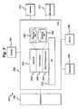
- FIG. 1illustrates a P2P communication system 100 .
- P2P communication system 100A first user of the P2P communication system (denoted “User A” 102 ) operates a user terminal 104 , which is shown connected to a P2P network 106 .
- the P2P network 106utilises a communication system such as the Internet, but is illustrated as a separate network in FIG. 1 for clarity.
- the user terminal 104may be, for example, a personal computer (“PC”), personal digital assistant (“PDA”), a mobile phone, a gaming device or other embedded device able to connect to the P2P network 106 .
- the user deviceis arranged to receive information from and output information to a user of the device.
- the user devicecomprises a display such as a screen and a keyboard and mouse.
- the user device 104is connected to the P2P network 106 via a network interface 108 such as a modem, and the connection between the user terminal 104 and the network interface 108 may be via a cable (wired) connection or a wireless connection.
- the user terminal 104is running a client 110 , provided by the P2P software provider.
- the client 110is a software program executed on a local processor in the user terminal 104 .
- the user terminal 104is also connected to a handset 112 , which comprises a speaker and microphone to enable the user to listen and speak in a voice call.
- the microphone and speakerdoes not necessarily have to be in the form of a traditional telephone handset, but can be in the form of a headphone or earphone with an integrated microphone, or as a separate loudspeaker and microphone independently connected to the user terminal 104 .
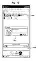
- FIG. 2An example of a user interface 200 of the client 110 executed on the user terminal 104 of User A 102 is shown illustrated in FIG. 2 .
- the client user interface 200displays the username 202 of User A 102 in the P2P system, and User A can set his own presence state (that will be seen by other users) using a drop down list by selecting icon 204 .
- the client user interface 200comprises a tab 206 labelled “contacts”, and when this tab is selected the contacts stored by the user in a contact list are displayed.
- a tab 206labelled “contacts”, and when this tab is selected the contacts stored by the user in a contact list are displayed.
- five contacts of other users of the P2P system(User B to F) are shown listed in contact list 208 . Each of these contacts have authorised the user of the client 110 to view their contact details and online presence and mood message information.
- Each contact in the contact listhas a presence status icon associated with it.
- the presence status icon for User B 210indicates that User B is “online”
- the presence icon for User C 212indicates that User C is “not available”
- the presence icon for User D 214indicates that User D's state is “do not disturb”
- the presence icon for User E 216indicates User E is “away”
- the presence icon for User F 218indicates that User F is “offline”.
- Further presence indicationscan also be included.
- the mood messages 220 of the contactsare the mood messages 220 of the contacts.
- the contact list for the users(e.g. the contact list 208 for User A) is stored in a contact server (not shown in FIG. 1 ).
- a contact server(not shown in FIG. 1 ).
- the contact serveris also used to store the user's own mood message (e.g. the mood message of User A 102 ) and a picture selected to represent the user (known as an avatar). This information can be downloaded to the client 110 , and allows this information to consistent for the user when logging on from different terminals.
- the client 110also periodically communicates with the contact server in order to obtain any changes to the information on the contacts in the contact list, or to update the stored contact list with any new contacts that have been added. Presence information is not stored centrally in the contact server. Rather, the client 110 periodically requests the presence information for each of the contacts in the contact list 208 directly over the P2P system. Similarly, the current mood message for each of the contacts, as well as a picture (avatar) that has been chosen to represent the contact, are also retrieved by the client 110 directly from the respective clients of each of the contacts over the P2P system.
- avatarpicture
- Calls to the P2P users in the contact listmay be initiated over the P2P system by selecting the contact and clicking on a “call” button 222 using a pointing device such as a mouse. Alternatively, the call may be initiated by typing in the P2P identity of a contact in the field 224 .
- the call set-upis performed using proprietary protocols, and the route over the network 106 between the calling user and called user is determined by the peer-to-peer system without the use of servers.
- an illustrative routeis shown between the caller User A ( 102 ) and the called party, User B ( 114 ), via other peers ( 116 , 118 , 120 ) of the P2P system. It will be understood that this route is merely an example, and that the call may be routed via fewer or more peers.
- VoIP packets from the user terminal 104are transmitted into the network 106 via the network interface 108 , and routed to the computer terminal 122 of User B 114 , via a network interface 123 .
- a client 124(similar to the client 110 ) running on the user terminal 122 of User B 114 decodes the VoIP packets to produce an audio signal that can be heard by User B using the handset 126 .
- the client 124 executed on user terminal 122encodes the audio signals into VoIP packets and transmits them across the network 106 to the user terminal 104 .
- the client 110 executed on user terminal 104decodes the VoIP packets from User B 114 , and produces an audio signal that can be heard by the user of the handset 112 .
- the VoIP packets for calls between P2P usersare passed across the network 106 only, and the PSTN network is not involved. Furthermore, due to the P2P nature of the system, the actual voice calls between users of the P2P system can be made with no central servers being used. This has the advantages that the network scales easily and maintains a high voice quality, and the call can be made free to the users. Additionally, calls can also be made from the client ( 110 , 122 ) using the P2P system to fixed-line or mobile telephones, by routing the call via a gateway 128 to the PSTN network 130 . Similarly, calls from fixed-line or mobile telephones can be made to the P2P system via the PSTN 130 and gateway 128 .
- FIG. 3illustrates a detailed view of the user terminal ( 104 ) on which is executed client 110 .
- the user terminal 104comprises a central processing unit (“CPU”) 302 , to which is connected a display 304 such as a screen, an input device such as a keyboard 306 , a pointing device such as a mouse 308 , a speaker 310 and a microphone 312 .
- the speaker 310 and microphone 312may be integrated into a handset 112 or headset, or may be separate.
- the CPU 302is connected to a network interface 108 as shown in FIG. 1 .
- FIG. 3also illustrates an operating system (“OS”) 314 executed on the CPU 302 .
- OSoperating system
- Running on top of the OS 314is a software stack 316 for the client 110 .
- the software stackshows a protocol layer 322 , a client engine layer 320 and a client user interface layer (“UI”) 318 .
- Each layeris responsible for specific functions. Because each layer usually communicates with two other layers, they are regarded as being arranged in a stack as shown in FIG. 3 .
- the operating system 314manages the hardware resources of the computer and handles data being transmitted to and from the network via the network interface 108 .
- the client protocol layer 322 of the client softwarecommunicates with the operating system 314 and manages the connections over the P2P system.
- the client engine layer 320comprises message manager functionality 324 and a message database 326 .
- the functionality of these elementswill be described in more detail hereinafter.
- the client engine 320also communicates with the client user interface layer 318 .
- the client engine 320may be arranged to control the client user interface layer 318 to present information to the user via the user interface of the client (as shown in FIG. 2 ) and to receive information from the user via the user interface.
- the control of the client user interface 318will be explained in more detail hereinafter.
- P2P client softwarepermits the inclusion of a large number of features that can be used by the users.
- P2P software providerit is useful for the P2P software provider to be able to inform the users of promotions that are available, and to give the users feedback in the case of detected problems or errors.
- Error messages and information/help messagescan be built into the client (i.e. hard-coded) such that they can be shown to the users as soon as the client is installed and executed on the user's terminal.
- thishas the significant disadvantage that the messages cannot be adapted or changed without the user installing a new version of the client.
- the P2P software providermay become aware that a particular feature is not being used frequently by the users, because the users are either unaware of its existence or do not understand how to use it. In such cases, hard-coded messages cannot change in order to inform the user of this feature.
- the P2P software providermay begin offering a new promotion or pricing plan, which cannot be communicated through the client until a new version is released with the hard-coded messages.
- FIG. 1A dynamic message delivery system is shown illustrated in FIG. 1 . Before the process by which the messages are delivered to the clients and displayed to the users is described, the process for creating the messages is outlined.
- the messagesare preferably created by an administrator affiliated with the P2P software provider. However, in some embodiments, this role could be fulfilled by a trusted third party.
- the administrator 132operates a user terminal 134 that is connected via a network interface 136 to a network 138 such as the Internet.
- Executed on a processor of the user terminal 134is a web browser program 140 .
- the web browser program 140is used to view web pages retrieved over the network 138 using the hypertext transfer protocol (“HTTP”).
- HTTPhypertext transfer protocol
- the network 106 used by the P2P system and the network 138 used by the administrator 132are both, in practice, the Internet. However, they are shown separately in FIG. 1 in order to distinguish between the information passed over the P2P system (network 106 ) and the information passed over the World Wide Web (network 138 ).
- FIG. 4shows a flowchart for the process by which the message is created by the administrator 132 .
- the administratorexecutes the web browser program 140 on the user terminal 134 .
- the administrator 132uses the web browser program 140 to log into a back office server ( 142 in FIG. 1 ) over the network 138 .
- the back office server 142displays to the administrator a selection of options that define the structure, content and properties of the message.
- the administratorselects the options required options to define what the message should display and when it should be displayed. The details of the message structure will be described with reference to FIG. 5 below.
- step S 408the administrator selects to save the message.
- the messageis saved by the back office server 142 in a content database ( 144 in FIG. 1 ).
- the messageis marked as requiring review.
- the reviewis an optional stage whereby the message is checked, e.g. for language. This may particularly be needed if translations of the messages into multiple languages are required.
- step S 410 and S 412the process waits for the message to be reviewed. Once the message has been approved, then in step S 414 the message stored in the content DB 144 is marked as ready for publication to the clients.
- Bundlesare created to minimise the amount of data that needs to be transmitted to the clients.
- a bundlecomprises the set of messages that are different to those messages that are pre-installed with the client. Therefore, the bundle constitutes changes or additions to the messages that the clients already contain.
- the bundleBy creating the bundles, only those messages that are not already present in the client are transmitted. Obviously, if only a single message is updated compared to those already installed in the client, then the bundle will comprise only one message.
- different versions of the clientswill contain different messages when they are installed on the user terminals, different bundles need to be compiled for different client versions. Each bundle is given a unique identifier in order to distinguish between them.
- the message 500comprises a message type field 502 which defines a particular category for the message.
- the message type field 502can define that the message is an information message, a user tip message or a promotion message.
- the type of messagecan be used to determine how the message is displayed in the client, for example background colours and icons can be displayed according to the type of message.
- the message 500also comprises a message content field 504 , which contains the actual information to be displayed to the users of the clients.
- the message content 504can comprise text, images, animation (e.g. flash animation) or a combination of the above. Example message content will be described hereinafter.
- the message 500further comprises a trigger 506 .
- the trigger 506defines an event that must occur in the client before the message content is displayed to the user of the client.
- Example triggersinclude, but are not limited to:
- a date, time or period(e.g. a specific date or every x days);
- a contactis added to the user's contact list
- the message 500can also define a condition 508 that must further be satisfied in order for the message to be shown to the user.
- Example conditionsinclude, but are not limited to:
- the client version number for the user initiating a call
- the client version number for a user receiving a call
- the languageis the client in;
- the P2P identity(username) of the user.
- the trigger 506defines the event that causes a particular condition 508 to be checked.
- the condition 508 in the messagedefines a value (e.g. a number, Boolean value or string) that must be checked against a certain property within the client before the display of the message can proceed.
- multiple conditionscan be defined, such that more than one of the above-listed conditions must be met in order for the message to be displayed.
- no conditioncan be set, such that only the trigger 506 is required in order for the message to be displayed.
- the message 500also comprises a link action field 510 .
- the link action 510defines the action that is taken by the client when the user clicks on a certain part of the message using the pointing device (e.g. a certain word, sequence of words or image).
- the link action 510can define that the client executes a web browser program, which navigates to a certain webpage.
- the link action 510can perform an action within the client itself (e.g. opening an option window, displaying the user's profile etc).
- a recycle field 512is present in the message 500 , which defines a set number of times that the message content 504 should be displayed. Even if the message has triggered ( 506 ) and met the condition ( 508 ) it will only be displayed if the number of times it has been displayed previously does not exceed the recycle value 512 . Therefore, the recycle value 512 ensures that a given message will only be shown a certain number of times, thereby preventing it from becoming annoying for the users.
- the recycle value 512can also be set such that a message can be displayed an indefinite number of times.
- the message 500further comprises start and end date values 514 .
- the start and end date values 514define a time interval during which the message should be displayed. This allows messages to only be displayed over a certain period, which is useful, for example, for time-sensitive marketing campaigns. However, the values for the start and end dates can be set such that the messages are always able to be displayed regardless of the date.
- the message 500also comprises a display location 516 for the message in the user interface of the client. Example display locations are illustrated in more detail with reference to FIGS. 8 to 12 . Furthermore, the message 500 comprises a priority field 518 .
- the priority field 518defines a priority level for the message in question, such that if the client attempts to display two or more messages in the same location at the same time, then only the message with the highest priority is displayed.
- a messagehas been created by the administrator 132 (as illustrated with reference to FIG. 4 ) comprising the properties described above with reference to FIG. 5 , and is stored in the content DB 144 .
- the administratorcan create a plurality of messages, each of which is stored in the content DB 144 .
- the process by which the messages are delivered to the clientsis now described with reference to FIG. 1 and FIG. 6 .
- the clients110 , 122 ) are configured to periodically check whether new messages are available to be downloaded.
- the message manager 324(as illustrated in FIG. 3 ) is responsible for triggering the periodic check for new messages.
- the periodicity of the message checkingcan be defined in order to balance the requirements of rapidly delivering new messages against the consequential network and server load. For example, the message checking period can be every 14 days, although any time period may be used.
- each clientIn order to prevent all the clients in the P2P system simultaneously attempting to retrieve messages, each client independently maintains its own timer of when messages were last retrieved. Therefore, as the users install and execute clients at different times, this ensures that the message retrieval is distributed over time, thereby reducing peak network loading.
- step S 602the client ( 110 , 122 ) sends a “request content” message via the network interface ( 108 , 123 ) over the P2P system.
- the “request content” messagecontains an identifier of the bundle of messages currently held by the client, which allows the message delivery system to determine which messages need to be provided to the client.
- the “request content” messagealso comprises the software version number for the client and the operating system used on the user terminal. This information is provided because different bundles of messages are compiled for different operating systems and client versions.
- the “request content” messageis transmitted from the client to a proxy server 146 over the P2P system.
- the function of the proxy server 146is to provide an interface between the peers of the P2P system and backend systems.
- the proxy server 146authenticates users of the P2P system to ensure that they are allowed to have access to the backend systems.
- the proxy server 146forwards the “request content” message to a message server 148 in step S 604 .
- the message server 146acts as the interface to the content DB 144 , and handles the delivery of messages to the clients.
- Multiple message serverscan be utilised in practice, in order to handle the load from a large number of clients requesting content.
- the message server 148reads the information regarding the software version, operating system and current message bundle ID from the “request content” message, and determines whether newer messages need to be sent to the client. The message server 148 compares the bundle ID for the most recent bundle for the given operating system and software version to the bundle ID from the client. If a newer bundle of messages exists then the message server prepares to send this to the client. If the client already has the latest bundle (i.e. no existing messages have been changed or new ones added since either the client was installed or since the last time the client requested messages from the message server) then the process stops without messages being transmitted to the client.
- the message server 148Presuming that a newer bundle exists, the message server 148 requests the newer bundle from the content DB 144 in step S 606 , and in step S 608 the newer message bundle is returned to the message server 148 .
- the message server 148can also comprise a cache element 150 , which is used to maintain a local cache of the most recent and commonly requested bundles. This can be advantageously utilised to avoid the need to fetch the bundle from the content DB 144 , thereby reducing the load on the database.
- step S 610the message bundle is transmitted from the message server 148 to the proxy server 146 .
- the proxy server 146then transmits the message bundle to the client 110 , 122 over the P2P system in step S 612 .
- the clientthen installs the message bundle.
- the new message bundlecan add new messages to the client, as well as make changes to existing messages or delete messages.
- the current bundle ID held at the clientis updated.
- the message bundleis received by the message manager 324 in the client and stored in the message DB 326 in the client 110 as illustrated in FIG. 3 .
- statistics about the messages displayed in the clientsare also collected in step S 614 .
- a set of statisticscan be collected for each message, which include: a message identifier; the total number of times the message was displayed; the total number of times the user closed the message; the total number of times a link in the message is clicked on; and the total amount of time, in seconds, that the message was displayed.
- Different statistics requirementscan be defined for different messages, and these statistics requirements can be pre-set in the installed client, or can be communicated to the client along with the bundle of messages.
- the statistics collected by the clientare reported back to the message server 148 periodically by the client.
- the clientcan be arranged to report statistics every four hours.
- the statisticsare collated and transmitted in S 616 to the proxy server 146 , and forwarded to the message server 148 in S 618 .
- the message server 148then stores the statistics in the statistics DB 152 in step S 620 .
- the steps of S 616 to S 620are repeated whenever the period for reporting statistics expires.
- step S 702the client 110 is executed on the user terminal 104 of the user 102 .
- step S 704the message manager 324 of the client 110 reads the messages stored in the message DB 326 .
- step S 706the message manager 324 extracts the message properties from the messages, specifically those properties described above with reference to FIG. 5 , including the trigger, conditions, recycle value, start and end dates and priority. The message manager 324 can then begin monitoring the client 110 behaviour to determine whether to display the message.
- step S 708the message manager 324 starts monitoring the triggers defined in the message.
- Example triggerswere outlined hereinabove. If, in step S 710 , the event defined by the trigger has not yet occurred, then the message manager 324 continues monitoring in S 708 . Alternatively, if the trigger event has occurred, then in step S 712 the conditions defined by the message are analysed. Example conditions were described hereinbefore. Typically, the conditions define a value that needs to be compared against a property within the client. The message manager 324 performs this comparison to determine if the condition is met. Note that multiple conditions may be defined in the message, which must all be met, or a null condition defined which is always met by default.
- step S 714the message manager 324 ceases to process the current message in question, and returns to monitoring triggers in step S 708 for the display of future messages.
- step S 716the message manager 324 checks the number of times that the message in question has been displayed. If it is found in step S 718 that this exceeds the recycle value for this message, then the message is not displayed, and the message manager returns to monitoring triggers in step S 708 . If, however, step S 718 finds that the recycle value has not been exceeded, then the process proceeds to step S 720 .
- step S 720the message manager 324 checks the start and end date values for this message. As mentioned before, these values define a time interval during which the message should be displayed. Therefore, in step S 720 , the message manager compares the current date to the start and end dates, to determine if the current date falls within them. If in step S 722 the current date is not within the start and end dates, then the message display should be skipped and the message manager 324 returns to monitoring the triggers in step S 708 .
- step S 724it is checked whether another message is already displayed at this display location, and if so, the priority levels of the message are compared.
- step S 726if the priority level of the current message is lower than another message already being displayed, then the current message is not displayed and step S 708 is returned to.
- step S 728the message display is not skipped, and in the step S 728 the message is displayed in the UI of the client 110 . More details on the display of the message in the client is provided with reference to FIGS. 8 to 13 below.
- step S 730the count of the number of times the message in question has been displayed is incremented, before the message manager 324 returns to monitoring the triggers in step S 708 .
- FIGS. 8 to 12illustrates example locations where the messages can be displayed in the client 110 .
- the messagesdefine a UI display location ( 516 ) which determines where the message is displayed.
- FIG. 8shows the user interface of the client 110 when displaying the contact list tab 206 , as described above with reference to FIG. 2 .
- the message placeholder 802comprises a close button 804 that removes the message from the display, thereby reverting the client to the form shown in FIG. 2 .
- FIG. 9shows the UI of the client 110 when the tab named “call phones” 902 is selected.
- This tab 902displays a keypad 904 , allowing the user to enter a telephone number to call.
- This tab 902shows an example message display location 906 with a close button 908 as described above.
- FIG. 10shows the UI of the client when the tab labelled “live” 1002 is selected.
- This tab 1002displays a list 1004 of ongoing and upcoming public conversations that can be joined by the user.
- This tab 1002also displays an example message location 1006 with a close button 1008 .
- FIG. 11illustrates the UI of the client 110 when the tab labelled “SkypeFind” 1102 is selected by the user.
- This tab 1102displays a directory service with fields 1104 for searching for businesses.
- This tab 1102displays an example message location 1106 with a close button 1108 .
- FIG. 12shows the tab displayed to the user of the client 110 when a call is in progress. In this case, User A 102 is in a call with User B 114 .
- the call tab 1202displays information 1204 about the user being called.
- An example message location 1206 with a close button 1208is shown at the bottom of the tab.
- FIG. 13illustrates a set of example messages that can be displayed in the UI locations described previously.
- Message 1302is a message displayed in the call tab 1202 as shown in FIG. 12 .
- This messageindicates to the user that the client 110 cannot detect any sound on the microphone, and hence there may be a problem with the audio settings.
- the trigger for this messageis making a call (of any type), and the condition is the audio gain level on the microphone.
- the link in the messagei.e. the link action 510 from FIG. 5 ) takes the user to the audio settings of the client 110 (i.e. a location internal to the client).
- Message 1304is a message displayed in the contacts tab 206 shown in FIG. 8 .
- the messageprompts the user to sign up for a voicemail service.
- the trigger for this messageis a missed call at the client, and the condition is that user has not subscribed to voicemail.
- the linktakes the user to an internet page where they can subscribe to the voicemail service.
- Message 1306is a message displayed in the call phones tab 902 shown in FIG. 9 .
- This messageinforms the user that they need to purchase credit in order to make calls to the PSTN network.
- the triggeris the user viewing the call phones tab 902 , and the condition is the user's credit balance is zero.
- the link actiontakes the user to an internet page where they can purchase credit.
- Message 1308is a promotional message displayed in the contacts list tab 206 shown in FIG. 8 .
- This messagepromotes a service whereby the user can purchase a telephone number to allow PSTN users to call their VoIP client.
- the trigger for this messageis time-based, such that it is displayed on a specified number of days.
- the conditionis that the user has not already signed up for this service—i.e. it is not desirable to promote a service the user already has.
- the linktakes the user to an internet page where they can subscribe to the service.
- Message 1310is a message displayed in the call tab 1202 shown in FIG. 12 . If the user was making a PSTN call (trigger) and the balance of his account goes to zero (condition) then the message is displayed.
- the linksdisplay webpages for the user to buy more credit and to set up an automatic credit recharging system.
- Message 1312is a promotional message displayed in the live 1002 or SkypeFind 1102 tabs in FIG. 10 or 11 respectively.
- This messageincludes images as well as text.
- the messagepromotes a subscription service.
- the triggeris time-based, and the condition is that the user has not already subscribed to the service.
- the linkdisplays a webpage in which the user can subscribe to the service.
- Message 1314is displayed in the call tab 1202 .
- the triggeris that the user is making a call to a PSTN number. There is no condition applied to this message.
- the messagenotifies the user that the call would be free if the other party also used the VoIP service, and the link takes the user to a webpage where the user can invite the other party to join the VoIP service.
- the messages displayed in the clientare relevant to the particular user of the client, due to using triggers and conditions that are dependent upon actions occurring within the client itself.
Landscapes
- Engineering & Computer Science (AREA)
- Business, Economics & Management (AREA)
- Human Resources & Organizations (AREA)
- Signal Processing (AREA)
- Computer Networks & Wireless Communication (AREA)
- Entrepreneurship & Innovation (AREA)
- Strategic Management (AREA)
- Marketing (AREA)
- Economics (AREA)
- Operations Research (AREA)
- Quality & Reliability (AREA)
- Tourism & Hospitality (AREA)
- Physics & Mathematics (AREA)
- General Business, Economics & Management (AREA)
- General Physics & Mathematics (AREA)
- Theoretical Computer Science (AREA)
- Data Mining & Analysis (AREA)
- Computer Hardware Design (AREA)
- Information Transfer Between Computers (AREA)
Abstract
Description
Claims (25)
Priority Applications (3)
| Application Number | Priority Date | Filing Date | Title |
|---|---|---|---|
| US11/937,069US9756004B2 (en) | 2007-11-08 | 2007-11-08 | Message delivery system and method |
| US15/692,896US10298532B2 (en) | 2007-11-08 | 2017-08-31 | Message delivery system and method |
| US16/386,074US20190245824A1 (en) | 2007-11-08 | 2019-04-16 | Message Delivery System and Method |
Applications Claiming Priority (1)
| Application Number | Priority Date | Filing Date | Title |
|---|---|---|---|
| US11/937,069US9756004B2 (en) | 2007-11-08 | 2007-11-08 | Message delivery system and method |
Related Child Applications (1)
| Application Number | Title | Priority Date | Filing Date |
|---|---|---|---|
| US15/692,896ContinuationUS10298532B2 (en) | 2007-11-08 | 2017-08-31 | Message delivery system and method |
Publications (2)
| Publication Number | Publication Date |
|---|---|
| US20090125593A1 US20090125593A1 (en) | 2009-05-14 |
| US9756004B2true US9756004B2 (en) | 2017-09-05 |
Family
ID=40624779
Family Applications (3)
| Application Number | Title | Priority Date | Filing Date |
|---|---|---|---|
| US11/937,069Active2031-12-22US9756004B2 (en) | 2007-11-08 | 2007-11-08 | Message delivery system and method |
| US15/692,896ActiveUS10298532B2 (en) | 2007-11-08 | 2017-08-31 | Message delivery system and method |
| US16/386,074AbandonedUS20190245824A1 (en) | 2007-11-08 | 2019-04-16 | Message Delivery System and Method |
Family Applications After (2)
| Application Number | Title | Priority Date | Filing Date |
|---|---|---|---|
| US15/692,896ActiveUS10298532B2 (en) | 2007-11-08 | 2017-08-31 | Message delivery system and method |
| US16/386,074AbandonedUS20190245824A1 (en) | 2007-11-08 | 2019-04-16 | Message Delivery System and Method |
Country Status (1)
| Country | Link |
|---|---|
| US (3) | US9756004B2 (en) |
Cited By (2)
| Publication number | Priority date | Publication date | Assignee | Title |
|---|---|---|---|---|
| US10298532B2 (en) | 2007-11-08 | 2019-05-21 | Skype | Message delivery system and method |
| US12136103B2 (en) | 2009-04-06 | 2024-11-05 | Vusura Technology Llc | Method and apparatus for presenting real-time video information in a call |
Families Citing this family (13)
| Publication number | Priority date | Publication date | Assignee | Title |
|---|---|---|---|---|
| US8621010B2 (en)* | 2008-03-17 | 2013-12-31 | International Business Machines Corporation | Method and system for protecting messaging consumers |
| US9143533B2 (en) | 2010-10-12 | 2015-09-22 | Skype | Integrating communications |
| CN103081404A (en)* | 2010-12-13 | 2013-05-01 | 三菱电机株式会社 | Alarm monitoring device and alarm monitoring method |
| US20120265808A1 (en)* | 2011-04-15 | 2012-10-18 | Avaya Inc. | Contextual collaboration |
| CN102843307A (en)* | 2011-06-22 | 2012-12-26 | 中兴通讯股份有限公司 | Transmission method and system of user internet state information and intelligent network platform |
| WO2015195577A1 (en)* | 2014-06-16 | 2015-12-23 | Ponce Karen | Communication logging system |
| KR20160046558A (en)* | 2014-10-21 | 2016-04-29 | 삼성전자주식회사 | Method and apparatus for outputing notification event |
| US10417447B2 (en)* | 2015-06-15 | 2019-09-17 | Arris Enterprises Llc | Selective display of private user information |
| US12142386B2 (en) | 2015-12-21 | 2024-11-12 | Evidation Health, Inc. | Sensor-based machine learning in a health prediction environment |
| US10929155B2 (en)* | 2018-05-11 | 2021-02-23 | Slack Technologies, Inc. | System, method, and apparatus for building and rendering a message user interface in a group-based communication system |
| US12027277B1 (en)* | 2019-12-05 | 2024-07-02 | Evidation Health, Inc. | Active learning for wearable health sensor |
| US12033761B2 (en) | 2020-01-30 | 2024-07-09 | Evidation Health, Inc. | Sensor-based machine learning in a health prediction environment |
| US12119115B2 (en) | 2022-02-03 | 2024-10-15 | Evidation Health, Inc. | Systems and methods for self-supervised learning based on naturally-occurring patterns of missing data |
Citations (66)
| Publication number | Priority date | Publication date | Assignee | Title |
|---|---|---|---|---|
| US5008853A (en)* | 1987-12-02 | 1991-04-16 | Xerox Corporation | Representation of collaborative multi-user activities relative to shared structured data objects in a networked workstation environment |
| US5583993A (en)* | 1994-01-31 | 1996-12-10 | Apple Computer, Inc. | Method and apparatus for synchronously sharing data among computer |
| US5835384A (en)* | 1994-07-08 | 1998-11-10 | Dade International Inc. | Inter-laboratory performance monitoring system |
| US5935384A (en)* | 1995-12-06 | 1999-08-10 | Kawano Paper Co. Ltd | Water-disintegrable paper having moisture retaining property and process for producing the same |
| US5995096A (en)* | 1991-10-23 | 1999-11-30 | Hitachi, Ltd. | Conference display control method and apparatus for an electronic conference for displaying either shared or local data and transferring local data |
| US6226678B1 (en)* | 1995-09-25 | 2001-05-01 | Netspeak Corporation | Method and apparatus for dynamically defining data communication utilities |
| US6237026B1 (en)* | 1997-12-31 | 2001-05-22 | Intel Corporation | Method and apparatus for automatic enrollment of a computer to a conference network or the like |
| US20010003827A1 (en)* | 1999-12-10 | 2001-06-14 | Akira Shimamura | Method, system and program product for remote maintenance of a peripheral device |
| US6263064B1 (en)* | 1999-01-29 | 2001-07-17 | International Thinklink Corporation | Centralized communication control center for visually and audibly updating communication options associated with communication services of a unified messaging system and methods therefor |
| US6269369B1 (en)* | 1997-11-02 | 2001-07-31 | Amazon.Com Holdings, Inc. | Networked personal contact manager |
| US20020076025A1 (en)* | 2000-12-18 | 2002-06-20 | Nortel Networks Limited And Bell Canada | Method and system for automatic handling of invitations to join communications sessions in a virtual team environment |
| US20020091769A1 (en)* | 2001-01-11 | 2002-07-11 | Drozdzewicz Piotr Jozef | Conferencing method |
| US6446113B1 (en)* | 1999-07-19 | 2002-09-03 | Groove Networks, Inc. | Method and apparatus for activity-based collaboration by a computer system equipped with a dynamics manager |
| US6463145B1 (en)* | 1999-01-29 | 2002-10-08 | Microsoft Corporation | Computer-implemented call forwarding options and methods therefor in a unified messaging system |
| US20020149618A1 (en)* | 2000-12-29 | 2002-10-17 | International Business Machines Corporation | Method and system for creating a theme of a place to be used as a template for other places |
| US20030004952A1 (en)* | 1999-10-18 | 2003-01-02 | Mark Nixon | Accessing and updating a configuration database from distributed physical locations within a process control system |
| US20030013951A1 (en)* | 2000-09-21 | 2003-01-16 | Dan Stefanescu | Database organization and searching |
| US20030050802A1 (en)* | 2001-04-03 | 2003-03-13 | Richard Jay | Medical service and prescription management system |
| US20030135565A1 (en)* | 2002-01-14 | 2003-07-17 | Julio Estrada | Electronic mail application with integrated collaborative space management |
| US20030144894A1 (en)* | 2001-11-12 | 2003-07-31 | Robertson James A. | System and method for creating and managing survivable, service hosting networks |
| US6606305B1 (en)* | 1998-11-25 | 2003-08-12 | Lucent Technologies Inc. | Apparatus, method and system for automatic telecommunication conferencing and broadcasting |
| US20040068481A1 (en)* | 2002-06-26 | 2004-04-08 | Praveen Seshadri | Network framework and applications for providing notification(s) |
| US20040259599A1 (en)* | 2003-06-19 | 2004-12-23 | Motokazu Okawa | Advertisement using cellular phone |
| WO2005009019A2 (en) | 2003-07-16 | 2005-01-27 | Skype Limited | Peer-to-peer telephone system and method |
| US20050053221A1 (en)* | 2001-02-27 | 2005-03-10 | Reding Craig L. | Method and apparatus for adaptive message and call notification |
| US20050180342A1 (en)* | 2000-02-29 | 2005-08-18 | Emeeting.Net, Inc. | Internet-enabled conferencing system and method accommodating PSTN and IP traffic |
| US20050227679A1 (en)* | 2004-04-13 | 2005-10-13 | Global Direct Management Corp. | Method and system of advertising in a mobile communication system |
| US7020880B2 (en)* | 1997-01-08 | 2006-03-28 | International Business Machines Corporation | Modular application collaborator for providing inter-operability between applications and monitoring errors to trigger execution of required compensating actions to undo interrupted transaction |
| US20060067252A1 (en)* | 2004-09-30 | 2006-03-30 | Ajita John | Method and apparatus for providing communication tasks in a workflow |
| US7024429B2 (en)* | 2002-01-31 | 2006-04-04 | Nextpage,Inc. | Data replication based upon a non-destructive data model |
| US20060085417A1 (en)* | 2004-09-30 | 2006-04-20 | Ajita John | Method and apparatus for data mining within communication session information using an entity relationship model |
| US20060149571A1 (en)* | 2004-12-30 | 2006-07-06 | Rodney Birch | Multi-channel enterprise communication management framework |
| US20060179121A1 (en)* | 2000-03-17 | 2006-08-10 | Digital Electronics Corporation | Control server, control terminal, control system, and recording medium storing control communication program |
| WO2006086353A2 (en)* | 2005-02-07 | 2006-08-17 | Mobiliad Investments & Trading Ltd. | System and method for transmitting and display of visual messages on screens of connected mobile devices |
| US20060209794A1 (en)* | 2004-08-13 | 2006-09-21 | Bae Kiwan E | Method and system for providing interdomain traversal in support of packetized voice transmissions |
| US20070115919A1 (en)* | 2005-10-14 | 2007-05-24 | 3Com Corporation | Method and system for using a packet-network telephone to schedule a conference call |
| US20070186157A1 (en)* | 2000-08-21 | 2007-08-09 | Walker Richard P | Simultaneous multi-user document editing system |
| US20070255715A1 (en)* | 2006-04-26 | 2007-11-01 | Bayhub, Inc. | Collaborative hub system for accessing and managing shared business content |
| US20080037565A1 (en)* | 2006-05-10 | 2008-02-14 | Murray Douglas G | Messaging systems and methods |
| US20080189388A1 (en)* | 2000-07-14 | 2008-08-07 | Knownow-Delaware | Delivery of any type of information to anyone anytime anywhere |
| US20080205616A1 (en)* | 2007-02-27 | 2008-08-28 | Mengshyang Teng | Method, apparatus and system for initiating calendar events |
| US20080209280A1 (en)* | 2007-02-28 | 2008-08-28 | Microsoft Corporation | Presence Aware Notification For Information Technology Management |
| US20080246605A1 (en)* | 2007-04-01 | 2008-10-09 | Howard Pfeffer | Methods and apparatus for providing multiple communications services with unified parental notification and/or control features |
| US20080320082A1 (en)* | 2007-06-19 | 2008-12-25 | Matthew Kuhlke | Reporting participant attention level to presenter during a web-based rich-media conference |
| US20090013045A1 (en)* | 2003-06-25 | 2009-01-08 | Oracle International Corporation | Mobile meeting and collaboration |
| US20090040948A1 (en)* | 2007-08-08 | 2009-02-12 | Alcatel Lucent | Speed conferencing |
| US20090048994A1 (en)* | 2007-05-31 | 2009-02-19 | Michael Applebaum | Portable Rule Specification System and Method for Monitoring Information Events |
| US20090109961A1 (en)* | 2007-10-31 | 2009-04-30 | John Michael Garrison | Multiple simultaneous call management using voice over internet protocol |
| US20090179983A1 (en)* | 2008-01-14 | 2009-07-16 | Microsoft Corporation | Joining users to a conferencing session |
| US7602895B2 (en)* | 2003-10-01 | 2009-10-13 | Aol Llc | Dynamic call response system |
| US7624172B1 (en)* | 2000-03-17 | 2009-11-24 | Aol Llc | State change alerts mechanism |
| US7702653B1 (en)* | 2004-06-30 | 2010-04-20 | Google Inc. | Methods and systems for triggering actions |
| US7778629B2 (en)* | 2007-01-10 | 2010-08-17 | International Business Machines Corporation | Method and system for handling potentially contentious situations upon receipt of an automatically connecting SMS message |
| US7809392B2 (en)* | 2005-12-14 | 2010-10-05 | Sony Ericsson Mobile Communications Ab | Text and voice capable mobile communication device |
| US7885187B2 (en)* | 2004-01-19 | 2011-02-08 | Samsung Electronics Co., Ltd. | System and method for providing unified messaging system service using voice over internet protocol |
| US7903796B1 (en)* | 2001-02-27 | 2011-03-08 | Verizon Data Services Llc | Method and apparatus for unified communication management via instant messaging |
| US7908322B2 (en)* | 2000-12-01 | 2011-03-15 | Radvision Ltd. | Initiation and support of video conferencing using instant messaging |
| US20110087738A1 (en)* | 2002-07-25 | 2011-04-14 | Linda Ruth Bartram | System and method for distributing shared storage for collaboration across multiple devices |
| US7969461B2 (en)* | 2006-03-30 | 2011-06-28 | Polycom, Inc. | System and method for exchanging connection information for videoconferencing units using instant messaging |
| US8001199B2 (en)* | 2002-11-18 | 2011-08-16 | Aol Inc. | Reconfiguring an electronic message to effect an enhanced notification |
| US8200775B2 (en)* | 2005-02-01 | 2012-06-12 | Newsilike Media Group, Inc | Enhanced syndication |
| US8229083B2 (en)* | 2007-01-10 | 2012-07-24 | International Business Machines Corporation | Method and system for automatically connecting to conference calls |
| US8311513B1 (en)* | 2007-06-27 | 2012-11-13 | ENORCOM Corporation | Automated mobile system |
| US8321274B2 (en)* | 2005-07-29 | 2012-11-27 | Yahoo! Inc. | Advertiser alerting system and method in a networked database search system |
| US8347088B2 (en)* | 2005-02-01 | 2013-01-01 | Newsilike Media Group, Inc | Security systems and methods for use with structured and unstructured data |
| US8438272B2 (en)* | 2010-08-31 | 2013-05-07 | Sap Ag | Methods and systems for managing quality of services for network participants in a networked business process |
Family Cites Families (29)
| Publication number | Priority date | Publication date | Assignee | Title |
|---|---|---|---|---|
| US6631271B1 (en)* | 2000-08-29 | 2003-10-07 | James D. Logan | Rules based methods and apparatus |
| WO2001045018A1 (en)* | 1999-12-17 | 2001-06-21 | Dorado Network Systems Corporation | Purpose-based adaptive rendering |
| US6944766B2 (en)* | 2000-05-02 | 2005-09-13 | Canon Kabushiki Kaisha | Information processing apparatus |
| US8064887B2 (en)* | 2000-08-29 | 2011-11-22 | Logan James D | Communication and control system using location aware devices for audio message storage and transmission operating under rule-based control |
| EP1209597A1 (en)* | 2000-11-24 | 2002-05-29 | Matsushita Electric Industrial Co., Ltd. | Methods for sending and receiving content and system for delivering content through use of e-mail |
| US20020169669A1 (en)* | 2001-03-09 | 2002-11-14 | Stetson Samantha H. | Method and apparatus for serving a message in conjuction with an advertisement for display on a world wide web page |
| US8068595B2 (en)* | 2002-03-15 | 2011-11-29 | Intellisist, Inc. | System and method for providing a multi-modal communications infrastructure for automated call center operation |
| AU2003238901A1 (en)* | 2002-06-07 | 2003-12-22 | Bellsouth Intellectual Property Corporation | Sytems and methods for establishing electronic conferencing over a distributed network |
| US20040187029A1 (en)* | 2003-03-21 | 2004-09-23 | Ting David M. T. | System and method for data and request filtering |
| US7231662B2 (en) | 2003-05-28 | 2007-06-12 | International Business Machines Corporation | Automated security tool for storage system |
| US20050071752A1 (en)* | 2003-09-24 | 2005-03-31 | Marlatt Jane E. | Forms management system |
| EP1698196B1 (en) | 2003-12-22 | 2010-06-02 | Telefonaktiebolaget L M Ericsson (Publ) | Technology-independent access selection based on application requirements and network status |
| US7912904B2 (en)* | 2004-03-31 | 2011-03-22 | Google Inc. | Email system with conversation-centric user interface |
| US8117102B1 (en)* | 2004-09-27 | 2012-02-14 | Trading Technologies International, Inc. | System and method for assisted awareness |
| US7860932B2 (en)* | 2005-04-04 | 2010-12-28 | Asaf Fried | Method and system for temporal delivery of email messages |
| US8682979B2 (en)* | 2005-07-01 | 2014-03-25 | Email2 Scp Solutions Inc. | Secure electronic mail system |
| US20070074250A1 (en)* | 2005-09-28 | 2007-03-29 | Sharp Kabushiki Kaisha | Sub-contents reproducing apparatus and contents related service providing system |
| US20070088852A1 (en)* | 2005-10-17 | 2007-04-19 | Zohar Levkovitz | Device, system and method of presentation of advertisements on a wireless device |
| US7921099B2 (en)* | 2006-05-10 | 2011-04-05 | Inquira, Inc. | Guided navigation system |
| US20080010148A1 (en)* | 2006-06-13 | 2008-01-10 | Ebay Inc. | Targeted messaging based on attributes |
| US20080040179A1 (en)* | 2006-08-14 | 2008-02-14 | Deutsche Boerse Ag | System and method for sharing information and causing an action based on that information |
| WO2008024972A2 (en)* | 2006-08-24 | 2008-02-28 | Aws Convergence Technologies, Inc. | System, method, apparatus, and computer media for distributing targeted alerts |
| JP2008146602A (en)* | 2006-12-13 | 2008-06-26 | Canon Inc | Document search apparatus, document search method, program, and storage medium |
| WO2009006542A2 (en)* | 2007-07-03 | 2009-01-08 | 3M Innovative Properties Company | System and method for assessing effectiveness of communication content |
| US20090049090A1 (en)* | 2007-08-13 | 2009-02-19 | Research In Motion Limited | System and method for facilitating targeted mobile advertisement |
| US20090061833A1 (en)* | 2007-08-30 | 2009-03-05 | Junius Ho | System, method and device to use messaging to implement programmatic actions |
| US8341663B2 (en)* | 2007-10-10 | 2012-12-25 | Cisco Technology, Inc. | Facilitating real-time triggers in association with media streams |
| US9756004B2 (en) | 2007-11-08 | 2017-09-05 | Skype | Message delivery system and method |
| US8407190B2 (en) | 2009-06-30 | 2013-03-26 | Commvault Systems, Inc. | Performing data storage operations with a cloud environment, including containerized deduplication, data pruning, and data transfer |
- 2007
- 2007-11-08USUS11/937,069patent/US9756004B2/enactiveActive
- 2017
- 2017-08-31USUS15/692,896patent/US10298532B2/enactiveActive
- 2019
- 2019-04-16USUS16/386,074patent/US20190245824A1/ennot_activeAbandoned
Patent Citations (69)
| Publication number | Priority date | Publication date | Assignee | Title |
|---|---|---|---|---|
| US5008853A (en)* | 1987-12-02 | 1991-04-16 | Xerox Corporation | Representation of collaborative multi-user activities relative to shared structured data objects in a networked workstation environment |
| US5995096A (en)* | 1991-10-23 | 1999-11-30 | Hitachi, Ltd. | Conference display control method and apparatus for an electronic conference for displaying either shared or local data and transferring local data |
| US5583993A (en)* | 1994-01-31 | 1996-12-10 | Apple Computer, Inc. | Method and apparatus for synchronously sharing data among computer |
| US5835384A (en)* | 1994-07-08 | 1998-11-10 | Dade International Inc. | Inter-laboratory performance monitoring system |
| US6226678B1 (en)* | 1995-09-25 | 2001-05-01 | Netspeak Corporation | Method and apparatus for dynamically defining data communication utilities |
| US5935384A (en)* | 1995-12-06 | 1999-08-10 | Kawano Paper Co. Ltd | Water-disintegrable paper having moisture retaining property and process for producing the same |
| US7020880B2 (en)* | 1997-01-08 | 2006-03-28 | International Business Machines Corporation | Modular application collaborator for providing inter-operability between applications and monitoring errors to trigger execution of required compensating actions to undo interrupted transaction |
| US6269369B1 (en)* | 1997-11-02 | 2001-07-31 | Amazon.Com Holdings, Inc. | Networked personal contact manager |
| US6237026B1 (en)* | 1997-12-31 | 2001-05-22 | Intel Corporation | Method and apparatus for automatic enrollment of a computer to a conference network or the like |
| US6606305B1 (en)* | 1998-11-25 | 2003-08-12 | Lucent Technologies Inc. | Apparatus, method and system for automatic telecommunication conferencing and broadcasting |
| US6263064B1 (en)* | 1999-01-29 | 2001-07-17 | International Thinklink Corporation | Centralized communication control center for visually and audibly updating communication options associated with communication services of a unified messaging system and methods therefor |
| US6463145B1 (en)* | 1999-01-29 | 2002-10-08 | Microsoft Corporation | Computer-implemented call forwarding options and methods therefor in a unified messaging system |
| US6446113B1 (en)* | 1999-07-19 | 2002-09-03 | Groove Networks, Inc. | Method and apparatus for activity-based collaboration by a computer system equipped with a dynamics manager |
| US20030004952A1 (en)* | 1999-10-18 | 2003-01-02 | Mark Nixon | Accessing and updating a configuration database from distributed physical locations within a process control system |
| US20010003827A1 (en)* | 1999-12-10 | 2001-06-14 | Akira Shimamura | Method, system and program product for remote maintenance of a peripheral device |
| US20050180342A1 (en)* | 2000-02-29 | 2005-08-18 | Emeeting.Net, Inc. | Internet-enabled conferencing system and method accommodating PSTN and IP traffic |
| US20060179121A1 (en)* | 2000-03-17 | 2006-08-10 | Digital Electronics Corporation | Control server, control terminal, control system, and recording medium storing control communication program |
| US7624172B1 (en)* | 2000-03-17 | 2009-11-24 | Aol Llc | State change alerts mechanism |
| US20080189388A1 (en)* | 2000-07-14 | 2008-08-07 | Knownow-Delaware | Delivery of any type of information to anyone anytime anywhere |
| US20070186157A1 (en)* | 2000-08-21 | 2007-08-09 | Walker Richard P | Simultaneous multi-user document editing system |
| US20030013951A1 (en)* | 2000-09-21 | 2003-01-16 | Dan Stefanescu | Database organization and searching |
| US7908322B2 (en)* | 2000-12-01 | 2011-03-15 | Radvision Ltd. | Initiation and support of video conferencing using instant messaging |
| US20020076025A1 (en)* | 2000-12-18 | 2002-06-20 | Nortel Networks Limited And Bell Canada | Method and system for automatic handling of invitations to join communications sessions in a virtual team environment |
| US20020149618A1 (en)* | 2000-12-29 | 2002-10-17 | International Business Machines Corporation | Method and system for creating a theme of a place to be used as a template for other places |
| US20020091769A1 (en)* | 2001-01-11 | 2002-07-11 | Drozdzewicz Piotr Jozef | Conferencing method |
| US20050053221A1 (en)* | 2001-02-27 | 2005-03-10 | Reding Craig L. | Method and apparatus for adaptive message and call notification |
| US7903796B1 (en)* | 2001-02-27 | 2011-03-08 | Verizon Data Services Llc | Method and apparatus for unified communication management via instant messaging |
| US20030050802A1 (en)* | 2001-04-03 | 2003-03-13 | Richard Jay | Medical service and prescription management system |
| US20030144894A1 (en)* | 2001-11-12 | 2003-07-31 | Robertson James A. | System and method for creating and managing survivable, service hosting networks |
| US20030135565A1 (en)* | 2002-01-14 | 2003-07-17 | Julio Estrada | Electronic mail application with integrated collaborative space management |
| US7024429B2 (en)* | 2002-01-31 | 2006-04-04 | Nextpage,Inc. | Data replication based upon a non-destructive data model |
| US20040068481A1 (en)* | 2002-06-26 | 2004-04-08 | Praveen Seshadri | Network framework and applications for providing notification(s) |
| US20110087738A1 (en)* | 2002-07-25 | 2011-04-14 | Linda Ruth Bartram | System and method for distributing shared storage for collaboration across multiple devices |
| US8001199B2 (en)* | 2002-11-18 | 2011-08-16 | Aol Inc. | Reconfiguring an electronic message to effect an enhanced notification |
| US20040259599A1 (en)* | 2003-06-19 | 2004-12-23 | Motokazu Okawa | Advertisement using cellular phone |
| US8028073B2 (en)* | 2003-06-25 | 2011-09-27 | Oracle International Corporation | Mobile meeting and collaboration |
| US20090013045A1 (en)* | 2003-06-25 | 2009-01-08 | Oracle International Corporation | Mobile meeting and collaboration |
| US20050122965A1 (en)* | 2003-07-16 | 2005-06-09 | Ahti Heinla | Peer-to-peer telephone system |
| WO2005009019A2 (en) | 2003-07-16 | 2005-01-27 | Skype Limited | Peer-to-peer telephone system and method |
| US7602895B2 (en)* | 2003-10-01 | 2009-10-13 | Aol Llc | Dynamic call response system |
| US7885187B2 (en)* | 2004-01-19 | 2011-02-08 | Samsung Electronics Co., Ltd. | System and method for providing unified messaging system service using voice over internet protocol |
| US20050227679A1 (en)* | 2004-04-13 | 2005-10-13 | Global Direct Management Corp. | Method and system of advertising in a mobile communication system |
| US7702653B1 (en)* | 2004-06-30 | 2010-04-20 | Google Inc. | Methods and systems for triggering actions |
| US20060209794A1 (en)* | 2004-08-13 | 2006-09-21 | Bae Kiwan E | Method and system for providing interdomain traversal in support of packetized voice transmissions |
| US20060067252A1 (en)* | 2004-09-30 | 2006-03-30 | Ajita John | Method and apparatus for providing communication tasks in a workflow |
| US7936863B2 (en)* | 2004-09-30 | 2011-05-03 | Avaya Inc. | Method and apparatus for providing communication tasks in a workflow |
| US20060085417A1 (en)* | 2004-09-30 | 2006-04-20 | Ajita John | Method and apparatus for data mining within communication session information using an entity relationship model |
| US20060149571A1 (en)* | 2004-12-30 | 2006-07-06 | Rodney Birch | Multi-channel enterprise communication management framework |
| US8200775B2 (en)* | 2005-02-01 | 2012-06-12 | Newsilike Media Group, Inc | Enhanced syndication |
| US8347088B2 (en)* | 2005-02-01 | 2013-01-01 | Newsilike Media Group, Inc | Security systems and methods for use with structured and unstructured data |
| WO2006086353A2 (en)* | 2005-02-07 | 2006-08-17 | Mobiliad Investments & Trading Ltd. | System and method for transmitting and display of visual messages on screens of connected mobile devices |
| US8321274B2 (en)* | 2005-07-29 | 2012-11-27 | Yahoo! Inc. | Advertiser alerting system and method in a networked database search system |
| US20070115919A1 (en)* | 2005-10-14 | 2007-05-24 | 3Com Corporation | Method and system for using a packet-network telephone to schedule a conference call |
| US7809392B2 (en)* | 2005-12-14 | 2010-10-05 | Sony Ericsson Mobile Communications Ab | Text and voice capable mobile communication device |
| US7969461B2 (en)* | 2006-03-30 | 2011-06-28 | Polycom, Inc. | System and method for exchanging connection information for videoconferencing units using instant messaging |
| US20070255715A1 (en)* | 2006-04-26 | 2007-11-01 | Bayhub, Inc. | Collaborative hub system for accessing and managing shared business content |
| US20080037565A1 (en)* | 2006-05-10 | 2008-02-14 | Murray Douglas G | Messaging systems and methods |
| US7778629B2 (en)* | 2007-01-10 | 2010-08-17 | International Business Machines Corporation | Method and system for handling potentially contentious situations upon receipt of an automatically connecting SMS message |
| US8229083B2 (en)* | 2007-01-10 | 2012-07-24 | International Business Machines Corporation | Method and system for automatically connecting to conference calls |
| US20080205616A1 (en)* | 2007-02-27 | 2008-08-28 | Mengshyang Teng | Method, apparatus and system for initiating calendar events |
| US20080209280A1 (en)* | 2007-02-28 | 2008-08-28 | Microsoft Corporation | Presence Aware Notification For Information Technology Management |
| US20080246605A1 (en)* | 2007-04-01 | 2008-10-09 | Howard Pfeffer | Methods and apparatus for providing multiple communications services with unified parental notification and/or control features |
| US20090048994A1 (en)* | 2007-05-31 | 2009-02-19 | Michael Applebaum | Portable Rule Specification System and Method for Monitoring Information Events |
| US20080320082A1 (en)* | 2007-06-19 | 2008-12-25 | Matthew Kuhlke | Reporting participant attention level to presenter during a web-based rich-media conference |
| US8311513B1 (en)* | 2007-06-27 | 2012-11-13 | ENORCOM Corporation | Automated mobile system |
| US20090040948A1 (en)* | 2007-08-08 | 2009-02-12 | Alcatel Lucent | Speed conferencing |
| US20090109961A1 (en)* | 2007-10-31 | 2009-04-30 | John Michael Garrison | Multiple simultaneous call management using voice over internet protocol |
| US20090179983A1 (en)* | 2008-01-14 | 2009-07-16 | Microsoft Corporation | Joining users to a conferencing session |
| US8438272B2 (en)* | 2010-08-31 | 2013-05-07 | Sap Ag | Methods and systems for managing quality of services for network participants in a networked business process |
Cited By (6)
| Publication number | Priority date | Publication date | Assignee | Title |
|---|---|---|---|---|
| US10298532B2 (en) | 2007-11-08 | 2019-05-21 | Skype | Message delivery system and method |
| US12136103B2 (en) | 2009-04-06 | 2024-11-05 | Vusura Technology Llc | Method and apparatus for presenting real-time video information in a call |
| US12141832B2 (en) | 2009-04-06 | 2024-11-12 | Vusura Technology Llc | Method and apparatus for content presentation in association with a telephone call |
| US12260426B2 (en) | 2009-04-06 | 2025-03-25 | Wendell D. Brown | Method and apparatus for content presentation in association with a telephone call |
| US12288221B2 (en) | 2009-04-06 | 2025-04-29 | Vusura Technology Llc | Method and apparatus for presenting multimedia content |
| US12299710B2 (en) | 2009-04-06 | 2025-05-13 | Vusura Technology Llc | Method and apparatus for presenting multimedia content |
Also Published As
| Publication number | Publication date |
|---|---|
| US20170366494A1 (en) | 2017-12-21 |
| US20090125593A1 (en) | 2009-05-14 |
| US20190245824A1 (en) | 2019-08-08 |
| US10298532B2 (en) | 2019-05-21 |
Similar Documents
| Publication | Publication Date | Title |
|---|---|---|
| US10298532B2 (en) | Message delivery system and method | |
| US9143533B2 (en) | Integrating communications | |
| US9584563B2 (en) | Communication system and method for content access | |
| US20100002685A1 (en) | Method and system for providing communication | |
| US8473545B2 (en) | Distributing presence information | |
| US7817792B2 (en) | Hyperlink-based softphone call and management | |
| US20110153868A1 (en) | Cloud-Based Application For Low-Provisioned High-Functionality Mobile Station | |
| WO2004054346A2 (en) | Dynamic user state dependent processing | |
| US20070220111A1 (en) | Personal communications browser client for remote use in enterprise communications | |
| US8635362B2 (en) | Communication system and method | |
| KR20150043369A (en) | Communications server apparatus, calling device and methods of operation thereof | |
| KR20160008552A (en) | Web platform with select-to-call functionality | |
| KR100810253B1 (en) | Method and system for providing service menu in communication system | |
| KR20160010535A (en) | Reverse number look up | |
| TWI533736B (en) | System and method for actuating a mobile device to initiate communication | |
| KR20070051236A (en) | Method and system for providing multimedia portal contents and additional services in communication system | |
| JP2013247427A (en) | Call support device, program, and method | |
| US8588397B2 (en) | Communication control system, communication control method, and recording medium including communication control program | |
| US20100284396A1 (en) | Communication system and method | |
| US7864761B2 (en) | Handling unsolicited content at a telecommunications terminal | |
| US9762623B1 (en) | Automatic call initiation in response to selecting tags in electronic documents and applications | |
| JP2014192752A (en) | Callback system and callback method |
Legal Events
| Date | Code | Title | Description |
|---|---|---|---|
| AS | Assignment | Owner name:SKYPE LIMITED, IRELAND Free format text:ASSIGNMENT OF ASSIGNORS INTEREST;ASSIGNORS:HIIR, TANEL;KARNER, KAIDO;KASESALU, PRIIT;AND OTHERS;REEL/FRAME:021224/0289;SIGNING DATES FROM 20080702 TO 20080708 Owner name:SKYPE LIMITED, IRELAND Free format text:ASSIGNMENT OF ASSIGNORS INTEREST;ASSIGNORS:HIIR, TANEL;KARNER, KAIDO;KASESALU, PRIIT;AND OTHERS;SIGNING DATES FROM 20080702 TO 20080708;REEL/FRAME:021224/0289 | |
| AS | Assignment | Owner name:JPMORGAN CHASE BANK, N.A., NEW YORK Free format text:SECURITY AGREEMENT;ASSIGNOR:SKYPE LIMITED;REEL/FRAME:023854/0805 Effective date:20091125 Owner name:JPMORGAN CHASE BANK, N.A.,NEW YORK Free format text:SECURITY AGREEMENT;ASSIGNOR:SKYPE LIMITED;REEL/FRAME:023854/0805 Effective date:20091125 | |
| AS | Assignment | Owner name:SKYPE LIMITED, CALIFORNIA Free format text:RELEASE OF SECURITY INTEREST;ASSIGNOR:JPMORGAN CHASE BANK, N.A.;REEL/FRAME:027289/0923 Effective date:20111013 | |
| AS | Assignment | Owner name:SKYPE, IRELAND Free format text:CHANGE OF NAME;ASSIGNOR:SKYPE LIMITED;REEL/FRAME:028691/0596 Effective date:20111115 | |
| STCF | Information on status: patent grant | Free format text:PATENTED CASE | |
| AS | Assignment | Owner name:MICROSOFT TECHNOLOGY LICENSING, LLC, WASHINGTON Free format text:ASSIGNMENT OF ASSIGNORS INTEREST;ASSIGNOR:SKYPE;REEL/FRAME:054586/0001 Effective date:20200309 | |
| MAFP | Maintenance fee payment | Free format text:PAYMENT OF MAINTENANCE FEE, 4TH YEAR, LARGE ENTITY (ORIGINAL EVENT CODE: M1551); ENTITY STATUS OF PATENT OWNER: LARGE ENTITY Year of fee payment:4 | |
| MAFP | Maintenance fee payment | Free format text:PAYMENT OF MAINTENANCE FEE, 8TH YEAR, LARGE ENTITY (ORIGINAL EVENT CODE: M1552); ENTITY STATUS OF PATENT OWNER: LARGE ENTITY Year of fee payment:8 |