US9755437B2 - Method, apparatus, and computer program product for wireless charging detection - Google Patents
Method, apparatus, and computer program product for wireless charging detectionDownload PDFInfo
- Publication number
- US9755437B2 US9755437B2US13/455,561US201213455561AUS9755437B2US 9755437 B2US9755437 B2US 9755437B2US 201213455561 AUS201213455561 AUS 201213455561AUS 9755437 B2US9755437 B2US 9755437B2
- Authority
- US
- United States
- Prior art keywords
- wireless
- charging device
- wireless charging
- charging
- characterizing
- Prior art date
- Legal status (The legal status is an assumption and is not a legal conclusion. Google has not performed a legal analysis and makes no representation as to the accuracy of the status listed.)
- Expired - Fee Related, expires
Links
Images


Classifications
- H—ELECTRICITY
- H02—GENERATION; CONVERSION OR DISTRIBUTION OF ELECTRIC POWER
- H02J—CIRCUIT ARRANGEMENTS OR SYSTEMS FOR SUPPLYING OR DISTRIBUTING ELECTRIC POWER; SYSTEMS FOR STORING ELECTRIC ENERGY
- H02J7/00—Circuit arrangements for charging or depolarising batteries or for supplying loads from batteries
- H02J7/00032—Circuit arrangements for charging or depolarising batteries or for supplying loads from batteries characterised by data exchange
- H02J7/00034—Charger exchanging data with an electronic device, i.e. telephone, whose internal battery is under charge
- H02J7/0004—
- H—ELECTRICITY
- H02—GENERATION; CONVERSION OR DISTRIBUTION OF ELECTRIC POWER
- H02J—CIRCUIT ARRANGEMENTS OR SYSTEMS FOR SUPPLYING OR DISTRIBUTING ELECTRIC POWER; SYSTEMS FOR STORING ELECTRIC ENERGY
- H02J50/00—Circuit arrangements or systems for wireless supply or distribution of electric power
- H02J50/10—Circuit arrangements or systems for wireless supply or distribution of electric power using inductive coupling
- H02J50/12—Circuit arrangements or systems for wireless supply or distribution of electric power using inductive coupling of the resonant type
- H—ELECTRICITY
- H02—GENERATION; CONVERSION OR DISTRIBUTION OF ELECTRIC POWER
- H02J—CIRCUIT ARRANGEMENTS OR SYSTEMS FOR SUPPLYING OR DISTRIBUTING ELECTRIC POWER; SYSTEMS FOR STORING ELECTRIC ENERGY
- H02J50/00—Circuit arrangements or systems for wireless supply or distribution of electric power
- H02J50/80—Circuit arrangements or systems for wireless supply or distribution of electric power involving the exchange of data, concerning supply or distribution of electric power, between transmitting devices and receiving devices
- H—ELECTRICITY
- H02—GENERATION; CONVERSION OR DISTRIBUTION OF ELECTRIC POWER
- H02J—CIRCUIT ARRANGEMENTS OR SYSTEMS FOR SUPPLYING OR DISTRIBUTING ELECTRIC POWER; SYSTEMS FOR STORING ELECTRIC ENERGY
- H02J50/00—Circuit arrangements or systems for wireless supply or distribution of electric power
- H02J50/90—Circuit arrangements or systems for wireless supply or distribution of electric power involving detection or optimisation of position, e.g. alignment
- H—ELECTRICITY
- H02—GENERATION; CONVERSION OR DISTRIBUTION OF ELECTRIC POWER
- H02J—CIRCUIT ARRANGEMENTS OR SYSTEMS FOR SUPPLYING OR DISTRIBUTING ELECTRIC POWER; SYSTEMS FOR STORING ELECTRIC ENERGY
- H02J7/00—Circuit arrangements for charging or depolarising batteries or for supplying loads from batteries
- H02J7/00032—Circuit arrangements for charging or depolarising batteries or for supplying loads from batteries characterised by data exchange
- H02J7/00036—Charger exchanging data with battery
- H—ELECTRICITY
- H02—GENERATION; CONVERSION OR DISTRIBUTION OF ELECTRIC POWER
- H02J—CIRCUIT ARRANGEMENTS OR SYSTEMS FOR SUPPLYING OR DISTRIBUTING ELECTRIC POWER; SYSTEMS FOR STORING ELECTRIC ENERGY
- H02J7/00—Circuit arrangements for charging or depolarising batteries or for supplying loads from batteries
- H02J7/00047—Circuit arrangements for charging or depolarising batteries or for supplying loads from batteries with provisions for charging different types of batteries
- H02J7/025—
- H02J2007/0001—
- H—ELECTRICITY
- H02—GENERATION; CONVERSION OR DISTRIBUTION OF ELECTRIC POWER
- H02J—CIRCUIT ARRANGEMENTS OR SYSTEMS FOR SUPPLYING OR DISTRIBUTING ELECTRIC POWER; SYSTEMS FOR STORING ELECTRIC ENERGY
- H02J50/00—Circuit arrangements or systems for wireless supply or distribution of electric power
- H02J50/60—Circuit arrangements or systems for wireless supply or distribution of electric power responsive to the presence of foreign objects, e.g. detection of living beings
- H—ELECTRICITY
- H02—GENERATION; CONVERSION OR DISTRIBUTION OF ELECTRIC POWER
- H02J—CIRCUIT ARRANGEMENTS OR SYSTEMS FOR SUPPLYING OR DISTRIBUTING ELECTRIC POWER; SYSTEMS FOR STORING ELECTRIC ENERGY
- H02J7/00—Circuit arrangements for charging or depolarising batteries or for supplying loads from batteries
- H02J7/00032—Circuit arrangements for charging or depolarising batteries or for supplying loads from batteries characterised by data exchange
- H02J7/00045—Authentication, i.e. circuits for checking compatibility between one component, e.g. a battery or a battery charger, and another component, e.g. a power source
- H04B5/0037—
- H—ELECTRICITY
- H04—ELECTRIC COMMUNICATION TECHNIQUE
- H04B—TRANSMISSION
- H04B5/00—Near-field transmission systems, e.g. inductive or capacitive transmission systems
- H04B5/70—Near-field transmission systems, e.g. inductive or capacitive transmission systems specially adapted for specific purposes
- H04B5/79—Near-field transmission systems, e.g. inductive or capacitive transmission systems specially adapted for specific purposes for data transfer in combination with power transfer
- H04W4/008—
- H—ELECTRICITY
- H04—ELECTRIC COMMUNICATION TECHNIQUE
- H04W—WIRELESS COMMUNICATION NETWORKS
- H04W4/00—Services specially adapted for wireless communication networks; Facilities therefor
- H04W4/80—Services using short range communication, e.g. near-field communication [NFC], radio-frequency identification [RFID] or low energy communication
Definitions
- the field of the inventionrelates to wireless short-range communication and more particularly to wireless charging detection.
- Wireless communication devicescan vary from battery powered handheld devices to stationary household and/or commercial devices utilizing electrical network as a power source. Due to rapid development of the wireless communication devices a number of areas capable of enabling entirely new types of communication applications have emerged.
- BluetoothTM communication protocolwhich operates in the 2.4 GHz ISM band.
- BluetoothTMis a short-range radio network, originally intended as a cable replacement.
- BluetoothTM Technical Specificationsare published by the BluetoothTM SIG, Inc.
- BluetoothTM Specification version 2.0 +EDRpublished Oct. 15, 2004 has the original functional characteristics of the first version BluetoothTM Basic Rate (BR) and adds the Enhanced Data Rate (EDR) feature.
- BluetoothTM Specification version 2.1 +EDRpublished Jul.
- B/EDRBasic Rate/Enhanced Data Rate
- Encryption Pause ResumeErroneous Data reporting, Extended Inquiry Response, Link Supervision Timeout Event, Packet Boundary Flag, Secure Simple Pairing, Sniff Subrating.
- BluetoothTM Specification version 3.0 +HSpublished Apr. 21, 2009, updated the standard to integrate the Alternate MAC/PHY and Unicast Connectionless Data features.
- BluetoothTM SIGpublished the BluetoothTM Core Specification, Version 4.0 (incorporated herein by reference), which includes the Extended Inquiry Response.
- An Extended Inquiry Responsemay be used to provide miscellaneous information during the inquiry response procedure. Data types may be defined for such things as local name and supported services, information that otherwise would have to be obtained by establishing a connection.
- a device that receives a local name and a list of supported services in an extended inquiry responsedoes not have to connect to do a remote name request and a service discovery protocol (SDP) service search, thereby shortening the time to useful information.
- SDPservice discovery protocol
- Method, apparatus, and computer program product example embodimentsprovide wireless charging detection.
- wireless charging devicetransmitting, by the wireless charging device, one or more wireless communication packets over the wireless communication interface, including the information usable for characterizing the charging capabilities of the wireless charging device, in response to receiving one or more wireless signals from the one or more other wireless devices;
- the wireless charging deviceprovides, by the wireless charging device, power to the one or more other wireless devices over a wireless power interface.
- the one or more wireless communication packetsinclude a BluetoothTM extended inquiry response packet.
- the one or more wireless communication packetsinclude a BluetoothTM service discovery protocol packet.
- the one or more wireless communication packetsinclude a BluetoothTM extended inquiry response packet that includes a data type indication to inform a receiving device that the information usable for characterizing charging capabilities of the wireless charging device exists.
- the one or more wireless communication packetsinclude a BluetoothTM FHS packet including an indication that the information usable for characterizing charging capabilities of the wireless charging device exists in a subsequent packet.
- the information usable for characterizing charging capabilities of the wireless charging deviceincludes one or more of wireless charging capability, status of charger, pictorial guidance information, wireless charging position, charger enabled status, or charger disabled status.
- the one or more wireless communication packets including information usable for characterizing charging capabilities of the wireless charging deviceincludes a BluetoothTM extended inquiry response packet.
- the one or more wireless communication packets including information usable for characterizing charging capabilities of the wireless charging deviceincludes a BluetoothTM service discovery protocol packet.
- the one or more wireless communication packets including information usable for characterizing charging capabilities of the wireless charging deviceincludes a BluetoothTM extended inquiry response packet that includes a data type indication to inform the apparatus that the information usable for characterizing charging capabilities of the remote device exists.
- the information usable for characterizing charging capabilities of the wireless charging deviceincludes one or more of wireless charging capability, status of charger, pictorial guidance information, wireless charging position, charger enabled status, or charger disabled status.
- At least one memoryincluding computer program code
- the at least one memory and the computer program codeconfigured to, with the at least one processor, cause the apparatus at least to:
- the at least one memory and the computer program codeconfigured to, with the at least one processor, cause the apparatus at least to:
- At least one memoryincluding computer program code
- the at least one memory and the computer program codeconfigured to, with the at least one processor, cause the apparatus at least to:
- wireless communication packetsincluding information usable for characterizing charging capabilities of the wireless charging device
- the at least one memory and the computer program codeconfigured to, with the at least one processor, cause the apparatus at least to:
- the at least one memory and the computer program codeconfigured to, with the at least one processor, cause the apparatus at least to:
- the at least one memory and the computer program codeconfigured to, with the at least one processor, cause the apparatus at least to:
- An example embodiment of the inventionincludes a computer program product comprising computer executable program code recorded on a computer readable non-transitory storage medium, the computer executable program code comprising:
- An example embodiment of the inventionincludes a computer program product comprising computer executable program code recorded on a computer readable non-transitory storage medium, the computer executable program code comprising:
- the example embodiments of the inventionprovide wireless charging detection.
- FIG. 1Adiscloses an example network diagram illustrating a wireless charging device equipped with a BluetoothTM communication protocol module in inquiry scanning mode receiving an inquiry packet from a rechargeable battery-powered BluetoothTM device in inquiry mode, in accordance with at least one embodiment of the present invention.
- FIG. 1 B 1discloses the example network diagram of FIG. 1A , of the wireless charging device responding to an inquiry packet from the rechargeable battery-powered BluetoothTM device, by providing information usable for characterizing charging capabilities of the wireless charging device.
- the wireless charging device in inquiry scanning modemay transmit the extended inquiry response (EIR) packet with the information usable for characterizing charging capabilities of the wireless charging device, in a normal BluetoothTM transmission, in accordance with at least one embodiment of the present invention.
- EIRextended inquiry response
- FIG. 1 B 2discloses an alternate example network diagram of FIG. 1A , of the wireless charging device responding to an SDP Service Search Attribute Request packet from the rechargeable battery-powered BluetoothTM device, by providing a SDP Service Search Attribute Response packet including information usable for characterizing charging capabilities of the wireless charging device.
- the wireless charging devicemay transmit the SDP Service Search Attribute Response packet with the information usable for characterizing charging capabilities of the wireless charging device, in a normal BluetoothTM transmission, in accordance with at least one embodiment of the present invention.
- FIG. 1Cillustrates the example network diagram of FIGS. 1A and 1 B 1 , after the rechargeable battery-powered BluetoothTM device has received the extended inquiry response packet including the information usable for characterizing charging capabilities of the wireless charging device and determining that the extended inquiry response packet includes information usable for characterizing charging capabilities of the wireless charging device, in accordance with at least one embodiment of the present invention.
- the rechargeable battery-powered BluetoothTM deviceresponds with a selection message indicating its selection of the wireless charging device.
- the wireless charging device equipped with the BluetoothTM communication protocol moduleresponds with a preferred position message.
- the rechargeable battery-powered BluetoothTM deviceresponds with a charging requirements message, in accordance with at least one embodiment of the present invention.
- FIG. 1Ddiscloses the example network diagram of FIGS. 1A, 1B, and 1C of the wireless charging device commencing providing wireless power to the rechargeable battery-powered BluetoothTM device, in accordance with at least one embodiment of the present invention.
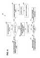
- FIG. 2discloses an example flow diagram of the overall operation of the wireless charging device equipped with a BluetoothTM communication protocol module and the rechargeable battery-powered BluetoothTM device performing the functions shown in FIGS. 1A to 1D , in accordance with at least one embodiment of the present invention.
- FIG. 3discloses an example flow diagram of the wireless charger device performing a scanning search for charged devices, in accordance with at least one embodiment of the present invention.
- FIG. 4discloses an example flow diagram of the rechargeable battery-powered BluetoothTM device determining the charging status of its rechargeable battery, in accordance with at least one embodiment of the present invention.
- FIG. 5Aillustrates an example embodiment of the invention, depicting an example flow diagram of an example method, from the point of view of the wireless charging device, in accordance with at least one embodiment of the present invention.
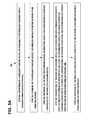
- FIG. 5Billustrates an example embodiment of the invention, depicting an example flow diagram of an example method, from the point of view of the rechargeable battery-powered device, in accordance with at least one embodiment of the present invention.
- FIG. 6Aillustrates an example embodiment of the invention, wherein pictorial guidance information showing the correct charging location, is included in the information usable for characterizing charging capabilities of the wireless charging device, in accordance with at least one embodiment of the present invention.
- FIG. 6Billustrates an example embodiment of the invention, wherein pictorial guidance information showing the appearance of the wireless charging device, is included in the information usable for characterizing charging capabilities of the wireless charging device, in accordance with at least one embodiment of the present invention.
- FIG. 6Cillustrates an example embodiment of the invention, wherein pictorial guidance information depicting the charger, may be generated from graphical elements or code showing the correct charging location, the graphical elements or code being included in the information usable for characterizing charging capabilities of the wireless charging device, in accordance with at least one embodiment of the present invention.
- FIG. 6Dillustrates an example embodiment of the invention, wherein pictorial guidance information depicting both the charger and the charged device, may be generated from graphical elements or code showing the correct charging location, the graphical elements or code being included in the information usable for characterizing charging capabilities of the wireless charging device, in accordance with at least one embodiment of the present invention.
- FIG. 7Adiscloses an example alternate network diagram illustrating a wireless charging device equipped with a plurality of antennas used to perform angle of arrival (AoA) estimation when receiving a device detection message from a rechargeable battery-powered BluetoothTM device, to assist in guiding the rechargeable battery-powered device into a proper position for a wireless charging operation, in accordance with at least one embodiment of the present invention.
- AoAangle of arrival
- FIG. 7Bdiscloses an example flow diagram of the wireless charger device determining a preferred charging position for a rechargeable battery-powered BluetoothTM device, in accordance with at least one embodiment of the present invention.
- FIG. 8illustrates an example embodiment of the invention, wherein examples of removable storage media are shown, based on magnetic, electronic and/or optical technologies, such as magnetic disks, optical disks, semiconductor memory circuit devices and micro-SD memory cards (SD refers to the Secure Digital standard) for storing data and/or computer program code as an example computer program product, in accordance with at least one embodiment of the present invention.
- SDrefers to the Secure Digital standard
- Short-range communication technologiesprovide communication solutions appropriate for many data applications, without the cost, traffic and legislative concerns of longer-range communication technologies.
- Popular short-range communication technologiesinclude Bluetooth basic rate/enhanced data rate (BR/EDR), Bluetooth Low Energy (LE), IEEE 802.11 wireless local area network (WLAN), Wireless Universal Serial Bus (WUSB), Ultra Wide-band (UWB), ZigBee (IEEE 802.15.4, IEEE 802.15.4a), and near field communication technologies, such as radio frequency identification (RFID) and near field communication (NFC) technology that enable contactless identification and interconnection of wireless devices.
- Bluetooth Technologyprovides an example of wireless short-range communication establishment.
- BluetoothTM Basebandis the part of the BluetoothTM system that implements the Media Access Control (MAC) and physical layer procedures to support the connection formation, exchange of data information streams, and ad hoc networking between BluetoothTM devices. Connection formation includes inquiry, inquiry scanning, inquiry response, paging, page scanning, and page response procedures.
- MACMedia Access Control
- Inquiryis a procedure where a BluetoothTM device transmits inquiry messages and listens for responses in order to discover the other BluetoothTM devices that are within the coverage area.
- BluetoothTM devicesuse the inquiry procedure to discover nearby devices, or to be discovered by devices in their locality.
- a BluetoothTM device that tries to find other nearby devicesis known as an inquiring device and actively sends inquiry requests.
- BluetoothTM devices that are available to be foundare known as discoverable devices, listen or scan for these inquiry requests, and send responses.
- the inquiry procedureuses dedicated physical channels for the inquiry requests and responses. The inquiry procedure does not make use of any of the architectural layers above the physical channel, although a transient physical link may be considered to be present during the exchange of inquiry and inquiry response information.
- BluetoothTM devicescommunicate with one another over a total bandwidth of 80 MHz divided into 79 physical channels of 1 MHz each.
- An inquiring device wanting to discover other devicesrepetitively probes a first set of 16 frequencies, probing two frequencies every 625 microseconds. It repeats this at least 256 times. Then, it repetitively probes a second set of 16 frequencies. The inquiring device will repeat entire cycle at least two times.
- the mastertransmits inquiry messages with the general or dedicated inquiry access code.
- the timing for inquiryis the same as for paging.
- the identity or ID packetconsists of the inquiry access code (IAC). It has a fixed length of 68 bits.
- the receiveruses a bit correlator to match the received packet to the known bit sequence of the ID packet.
- IACinquiry access code
- a devicemay enter inquiry substate. In this substate, it may repeatedly transmit the inquiry message (ID packet) at different hop frequencies.
- the inquiry hop sequenceis derived from the Lower Address Part (LAP) of the General Inquiry Access Code (GIAC).
- LAPLower Address Part
- GIACGeneral Inquiry Access Code
- a device that allows itself to be discoveredmay regularly enter the inquiry scan substate to respond to inquiry messages.
- the inquiry responseis optional: a device is not forced to respond to an inquiry message.
- the discovering devicecollects the BluetoothTM device addresses and clocks of all devices that respond to the inquiry message.
- the discovering devicealso collects extended information (e.g. local name and supported services) from devices that respond with an extended inquiry response packet. It may then, if desired, make a connection to any one of the discovered devices by means of the page procedure described below.
- the inquiry message broadcast by the sourcedoes not contain any information about the source. However, it may indicate which class of devices should respond.
- GIACgeneral inquiry access code
- DIACdedicated inquiry access codes
- LIACLimited Inquiry Access Code
- Inquiry scanis a procedure where a BluetoothTM device listens for inquiry messages received on its inquiry scan physical channel. A device using one of its inquiry scan channels remains passive on that channel until it receives an inquiry message on this channel from another BluetoothTM device. This is identified by the appropriate inquiry access code.
- the inquiry scanning devicewill then follow the inquiry response procedure to return a response to the inquiring device.
- the inquiry scan substateis very similar to the page scan substate. However, instead of scanning for the device's device access code, the receiver may scan for the inquiry access code long enough to completely scan for 16 inquiry frequencies.
- the inquiry procedureuses 32 dedicated inquiry hop frequencies according to the inquiry hopping sequence. These frequencies are determined by the general inquiry address.
- the phaseis determined by the native clock of the device carrying out the inquiry scan. Instead of, or in addition to, the general inquiry access code, the device may scan for one or more dedicated inquiry access codes. However, the scanning may follow the inquiry scan hopping sequence determined by the general inquiry address.
- the inquiry scan intervalmay be less than or equal to 2.56 s.
- An inquiry response packetis transmitted from the slave to the master after the slave has received an inquiry message.
- This packetcontains information necessary for the inquiring master to page the slave and follows 625 microseconds after the receipt of the inquiry message.
- the inquiry response packetis received by the master at the hop frequency when the inquiry message received by the slave was first in the master-to-slave slot.
- the slave response substate for inquiriesdiffers completely from the slave response substate applied for pages.
- the recipientmay return an inquiry response (FHS) packet containing the recipient's device address (BD_ADDR) and other parameters. If the recipient has non-zero extended inquiry response data to send, it may return an extended inquiry response packet after the FHS packet.
- BD_ADDRdevice address
- the slaveOn the first inquiry message received in the inquiry scan substate the slave may enter the inquiry response substate. If the slave has non-zero extended inquiry response data to send it may return an FHS packet, with the extended inquiry response bit set to one, to the master 625 microseconds after the inquiry message was received. It may then return an extended inquiry response packet 1250 microseconds after the start of the FHS packet. If the slave's extended inquiry response data is all zeroes the slave may only return an FHS packet with the extended inquiry response bit set to zero.
- a contention problemcould arise when several devices are in close proximity to the inquiring device or master and all respond to an inquiry message at the same time. However, because every device has a free running clock it is highly unlikely that they all use the same phase of the inquiry hopping sequence. In order to avoid repeated collisions between devices that wake up in the same inquiry hop channel simultaneously, a device will back-off for a random period of time. Thus, if the device receives an inquiry message and returns an FHS packet, it will generate a random number, RAND, between 0 and MAX_RAND. For scanning intervals greater than or equal to 1.28 seconds MAX_RAND will be 1023, however, for scanning intervals less than 1.28 s MAX_RAND may be as small as 127.
- a profile that uses a DIACmay choose to use a smaller MAX_RAND than 1023 even when the scanning interval is greater than or equal to 1.28 s.
- the slavewill return to the CONNECTION or STANDBY state for the duration of at least RAND time slots. Before returning to the CONNECTION and STANDBY state, the device may go through the page scan substate. After at least RAND slots, the device will add an offset of 1 to the phase in the inquiry hop sequence (the phase has a 1.28 second resolution) and return to the inquiry scan substate again. If the slave is triggered again, it will repeat the procedure using a new RAND. The offset to the clock accumulates each time an FHS packet is returned.
- a slavemay respond multiple times, but on different frequencies and at different times.
- Reserved synchronous slotsshould have priority over response packets; that is, if a response packet overlaps with a reserved synchronous slot, it will not be sent, but the next inquiry message is awaited. If a device has extended inquiry response data to send, but the extended inquiry response packet overlaps with a reserved synchronous slot, the FHS packet may be sent with the EIR bit set to zero.
- step 1the master transmits an inquiry message using the inquiry access code and its own clock.
- step 2the slave responds with the FHS packet containing the slave's BluetoothTM device address, native clock and other slave information.
- This FHS packetis returned at times that tend to be random.
- the FHS packetis not acknowledged in the inquiry routine, but it is retransmitted at other times and frequencies as long as the master is probing with inquiry messages.
- step 3if the slave has non-zero extended inquiry response data, it sends an extended inquiry response packet to the master.
- An Extended Inquiry Responsemay be used to provide miscellaneous information during the inquiry response procedure.
- Data typesare defined for such things as local name and supported services, information that otherwise would have to be obtained by establishing a connection.
- a device that receives a local name and a list of supported services in an extended inquiry responsedoes not have to connect to do a remote name request and a service discovery protocol (SDP) service search, thereby shortening the time to useful information.
- SDPservice discovery protocol
- the extended inquiry response packetis an Asynchronous Connection-oriented Logical transport (ACL) data medium rate (DM) packet with type DM1, DM3, DM5, DH1, DH3 or DH5.
- ACLAsynchronous Connection-oriented Logical transport
- DMdata medium rate
- the packetis sent on the same frequency as the (frequency hop synchronization) FHS packet, 1250 microseconds after the start of the FHS packet.
- the logical transport address (LT_ADDR)may be set to zero.
- TYPEmay be one of DM1, DM3, DM5, DH1, DH3 or DH5.
- FLOW, ARQN and SEQNmay all be set to zero and ignored during receipt.
- the header error check (HEC) linear feedback shift registermay be initialized with the same default check initialization (DCI) as for the FHS packet.
- DCIdata check initialization
- LLIDlogical link identifier
- L2CAPlogical link control and adaptation control
- FLOWmay be set to zero and ignored upon receipt.
- the length of the payload body (LENGTH)may be smaller than or equal to 240 bytes.
- the cyclic redundancy check (CRC) linear feedback shift register (LFSR)may be initialized with the same DCI as for the FHS packet.
- the data whitening LFSRmay be initialized with the same value as for the FHS packet.
- the length of the payload body (LENGTH)may be smaller than or equal to 240 bytes.
- the CRC LFSRmay be initialized with the same DCI as for the FHS packet.
- the data whitening LFSRmay be initialized with the same value as for the FHS packet.
- the payload datahas two parts, a significant part followed by a non-significant part.
- the significant partcontains a sequence of data structures.
- the non-significant partcontains all zero octets.
- the basebandmay not change any octets in the significant part. When transmitting data, the non-significant part octets may be omitted from the payload.
- a devicemay store a single extended inquiry response packet. This packet may be used with all inquiry access codes (IACs).
- Pageis the initial phase of the connection procedure where a device transmits a train of page messages until a response is received from the target device or a timeout occurs.
- Page scanis a procedure where a device listens for page messages received on its page scan physical channel. In forming a connection, the paging device will become the master and the page scan device will become the slave in a piconet. Initially, after the slave has received an inquiry message, an inquiry response packet is transmitted from the slave to the master. The inquiry response packet sent from the slave contains information necessary for the inquiring master to page the slave, such as BluetoothTM device address and the clock of the slave device.
- the BluetoothTM device that will become the mastercarries out a page procedure by transmitting page messages in connection request packets to the specified BluetoothTM slave device that carries out a page scanning procedure to listen for connection request packets from the paging device.
- a connectable BluetoothTM devicelistens for a page request on its page scan channel and, once received, enters into a sequence of exchanges with the paging device. In order for a device to connect to another device, it performs frequency hopping all page scan channel frequencies, sending a page request on each frequency and listening for a response.
- the page scan channeluses an access code derived from the scanning device's BluetoothTM device address BD_ADDR to identify communications on the channel.
- the page scan channeluses a slower hopping rate than the hop rate of the paging device, using the BluetoothTM device clock of the scanning device as an input.
- a device listening on its page scan channelremains passive until it receives a page request from another BluetoothTM device, identified by the page scan channel access code.
- the two deviceswill then follow the page procedure to form a connection where the paging device is the master and the page scan device is the slave in a piconet.
- ituses the page scan channel of the target device in order to send page requests. If the paging device does not know the phase of the target device's page scan channel, it does not know the current hop frequency of the target device.
- the paging devicetransmits page requests on each of the page scan hop frequencies and listens for a page response. This is done at a faster hop rate, allowing the paging device to cover all page scan frequencies in a short period of time.
- the paging devicemay have some knowledge of the target device's BluetoothTM clock, such as indicated during a previous inquiry transaction between the two devices, and may be able to predict the phase of the target device's page scan channel. It may use this information to optimize the synchronization of the paging and page scanning process and speed up the formation of the connection.
- SDPService Discovery Protocol
- Bluetooth devicesare designed to find other Bluetooth devices within their ten meter radio communications range and to discover what services they offer, using a service discovery protocol (SDP).
- SDP searching functionrelies on links being established between the requesting Bluetooth device in a client role and the responding Bluetooth device in a server role. Once a link has been established, it can be used to find out about services in the responding Bluetooth device and how to connect to them.
- SDPService Discovery Protocol
- UUIDUniversally Unique Identifier
- Bluetooth profilesare supported by the headset (headset profile, hands free profile, advanced audio distribution profile, etc.) and the protocol multiplexor settings needed to connect to each of them.
- Each serviceis identified by a Universally Unique Identifier (UUID), with official services (Bluetooth profiles) assigned a short form UUID (16 bits rather than the full 128).
- UUIDUniversally Unique Identifier
- Rechargeable batteries in cellular phones and other portable communication devicescan be recharged with household alternating current (AC) power coupled through a voltage reduction transformer, an alternating-to-direct current converter, and appropriate battery monitoring and charging circuits. They can also be recharged with a 12-volt cigarette lighter socket provided in an automobile coupled through a DC voltage reduction circuit and appropriate battery monitoring and charging circuits.
- ACalternating current
- the portable communication devicemust be plugged into the household AC power source or into the automobile power source, limiting the mobility of the communication device.
- a power source circuit in a wireless charging devicedrives a resonant frequency circuit that produces a source alternating current in a frequency range for example between 50 kHz and 20 MHz, which is driven through a transmitting coil in the charging device.
- the alternating magnetic field produced by the transmitting coilinductively couples with a corresponding receiving coil in the cellular phone or other portable communication device, thereby producing a corresponding induced alternating current that drives a circuit at its resonant frequency in the range for example between 50 kHz and 20 MHz to produce an output AC voltage.
- a conversion circuit in the cellular phone or other portable communication deviceuses a transformer to adjust the output AC voltage, an alternating-to-direct current converter, and appropriate battery monitoring and charging circuits to produce an appropriate DC charging voltage for the rechargeable battery.
- Wireless charging padsare generally shaped as a flat plate and typically have an active charging surface approximately the size of a sheet of typing paper. Other shapes for the charging pad may not be flat, but instead shaped to conform to particularly shaped user devices to be charged, for example a charger shaped as a wall-mounted holder for a garden tool. Wireless charging pads use multiple transmitting coils or a single large transmitting coil to distribute their magnetic flux over the active charging surface.
- the mobile devicecharged device
- the mobile devicemay provide control for the charger, particularly indicating desirable power levels and when to stop charging.
- At least three typical coil alignment strategiesare [1] guided positioning with tactile or optical feedback (e.g. a magnet or positioning markers), [2] free positioning using a moving coil, and [3] free positioning using coil array.
- At least three techniquesmay be used by the charger, separately or together, to initially react to a new potentially chargeable device. These are [1] capacitance change (to detect a device), [2] resonance change (to detect device presence and location), and [3] digital ping (to get the desired power levels). The digital ping is also used to detect when the charged device has left the charging area.
- wireless charger existencemay be advertised by the wireless charger using a short-range communications protocol.
- a mobile wireless device using the short-range communications protocolmay search for a wireless charger, based on the charged state of the mobile device's battery.
- the short-range communications protocolmay be used to exchange charging information between the wireless charger and the mobile wireless device to be charged.
- the wireless chargermay initialize the charging operation by beginning to feed current to the coils or other similar elements.
- the charged deviceis guided to the correct position relative to the other device. The charger keeps periodically checking for the presence of the charged device and discontinues charging when the charged device is no longer detected.
- Bluetooth technologyprovides an example of a wireless short-range communication protocol applied to communications between a wireless charger device and a rechargeable battery-powered device.
- wireless charger existencemay be advertised by the wireless charger using the Bluetooth communications protocol.
- a mobile wireless device using the Bluetooth communications protocolmay search for a wireless charger, based on the charged state of the mobile device's battery.
- the Bluetooth communications protocolmay be used to exchange charging information between the wireless charger and the mobile wireless device to be charged.
- the wireless chargermay initialize the charging operation by beginning to feed current to the coils or other similar elements.
- the charged deviceis guided to the correct position relative to the other device. The charger keeps periodically checking for the presence of the charged device and discontinues charging when the charged device is no longer detected.
- a wireless chargeruses the Bluetooth communications protocol to advertise wireless charging capability in a service discovery protocol (SDP) record or an extended inquiry response (EIR) packet.
- SDPservice discovery protocol
- EIRextended inquiry response
- the values of at least one of these fieldsmay be set according to the status of the charger (wireless charging capable/not capable, free/occupied).
- the Bluetooth communications protocolmay be used to exchange information about wireless charging itself (for capable devices) or to send guiding information (e.g. a picture) to the charged device.
- FIG. 1Adiscloses an example network diagram illustrating a wireless charging device 100 equipped with a BluetoothTM communication protocol module MAC 77 ′ and radio 78 ′ in inquiry scanning mode receiving a device detection message 150 , for example an inquiry packet, from a rechargeable battery-powered BluetoothTM device 200 in inquiry mode, in accordance with at least one embodiment of the present invention.
- the wireless charging device 100may provide wireless power 110 to the rechargeable battery-powered device 200 .
- the rechargeable battery-powered device 200may be primarily a communications device, such as a cell phone, personal digital assistant (PDA), pager, BluetoothTM headset, or the like.
- the rechargeable battery-powered device 200may also be a personal computing device such as a laptop, palmtop, or tablet computer.
- the rechargeable battery-powered device 200may also be an embedded micro-controller in an appliance, an engine control computer, a micro-controller in a digital TV, a micro-controller in a global positioning system (GPS) device, or the like.
- the rechargeable battery-powered device 200may also be a video game console or a digital toy, such as a programmable robot.
- a power source circuit 102 in the wireless charging device 100drives a power frequency driver and interface 104 that produces a source alternating current in a frequency range between 50 kHz and 20 MHz through the power transmission coil 120 , which will provide energy to recharge rechargeable batteries that would be located in the battery holder 216 of the rechargeable battery-powered device 200 during normal use.
- the power control circuits 106control the power level output by the charger 100 .
- the power transmission coil 120 of the wireless charging device 100may be brought near the rechargeable battery-powered device 200 to couple the magnetic flux with the power receiving coil 220 , using contact-less electromagnetic induction.
- the contact-less electromagnetic inductionmay provide sufficient power to operate the rechargeable battery-powered device 200 .
- the power source circuit 102 in the wireless charging device 100drives a resonant frequency circuit 104 that produces a source alternating current in a frequency range for example between 50 kHz and 20 MHz, which is driven through the transmitting coil 120 in the charging device 100 .
- the alternating magnetic field produced by the transmitting coil 120inductively couples with the corresponding receiving coil 220 in the rechargeable battery-powered device 200 .
- Both coilsmay be tuned to the same electromagnetic frequency, enabling energy to be efficiently transferred from the wireless charger device 100 to the rechargeable battery-powered device 200 .
- the resonanceenables charging over a longer distance compared to inductive charging.
- the induced alternating currentdrives a interface circuit 212 at its resonant frequency in the range for example between 50 kHz and 20 MHz to produce an output AC voltage.
- the power transmission coil 120may be any suitable shape such as printed coil, multilayer coils, wired coils, and the like.
- a separate printed wiring board 122may be omitted and the coil 120 may incorporated into the body of the printed wiring board or it may be glued to a plastic substrate forming a charging plate.
- the power transmission coil 120may have a relatively large area.
- the current carrying wires of the power transmission coil 120generate magnetic field lines that form concentric circles of magnetic flux around the wires 120 .
- the magnetic flux proximate to the power receiving coil 220 of the rechargeable battery-powered device 200couples with the power receiving coil 220 , using contact-less electromagnetic induction.
- the contact-less electromagnetic inductionprovides sufficient power to the relatively small power receiving coil 220 , to charge rechargeable batteries that would be located in the battery holder 216 of the rechargeable battery-powered device 200 during normal use.
- the contact-less electromagnetic inductionalso provides sufficient power to operate the rechargeable battery-powered device 200 .
- control 22may include a central processing unit (CPU) 60 ′, random access memory (RAM) 62 ′, and programmable read only memory (PROM) 64 ′.
- the PROM 64 ′may store programmed instructions.
- MAC 77 of the rechargeable battery-powered device 200may use a suitable short-range communications protocol, such as BluetoothTM, Radio Frequency Identification (RFID), Near Field Communication (NFC), Infrared Data Association (IrDA), Ultra Wide Band (UWB), or IEEE 802.11 WLAN, for example, that is respectively wirelessly coupled to a corresponding transceiver of the same type coupled to the software update server.
- RFIDRadio Frequency Identification
- NFCNear Field Communication
- IrDAInfrared Data Association
- UWBUltra Wide Band
- IEEE 802.11 WLANIEEE 802.11 WLAN
- BluetoothTM short-range communications protocolAn example of the BluetoothTM short-range communications protocol is described, for example, BluetoothTM devices is described in the BluetoothTM Specification, Version 4, Jun. 30, 2010, incorporated herein by reference.
- Radio Frequency IdentificationRFID
- ISO 11785air interface protocol
- ISO 14443air interface protocol
- ISO 15693incorporated herein by reference.
- NFCNear Field Communication
- IrDAInfrared Data Association
- Ultra Wide Band (UWB) short-range communications protocolis described, for example, in WiMedia Common Radio Platform Specification, Version 1.5 (2010), incorporated herein by reference.
- IEEE 802.11 WLAN communications protocolAn example of the IEEE 802.11 WLAN communications protocol is described, for example, in IEEE 802.11-2007, Wireless Medium Access Control (MAC) and Physical Layer (PHY) Specifications, June 2007 (incorporated herein by reference).
- MACWireless Medium Access Control
- PHYPhysical Layer
- the control processor 20may include the CPU 60 , RAM 62 , and PROM 64 that may be coupled to the control interface 205 .
- the CPU 60may be a dual processor or multi-processor.
- the PROM 64may store programmed operations including.
- the control processor 20may be embodied as a single integrated circuit semiconductor chip, known as a baseband system on chip.
- the control processor 20may be embodied as two or more integrated circuit semiconductor chips in a chip set.
- the PROM 64may be a flash memory or other non-volatile computer storage chip that may be electrically erased and reprogrammed.
- removable storage mediabased on magnetic, electronic and/or optical technologies such as magnetic disks, optical disks, semiconductor memory circuit devices and micro-SD memory cards (SD refers to the Secure Digital standard) are shown at 126 and in FIG. 8 , and may serve, for instance, as a data input/output means.
- Codemay include any interpreted or compiled computer language including computer-executable instructions. The code and/or data may be used to create software modules such as operating systems, communication utilities, user interfaces, more specialized program modules, etc.
- the control processor 20may manage the communication functions of the rechargeable battery-powered device 200 .
- Example communication functionsmay be radio control functions such as signal modulation, encoding, radio frequency shifting, and the like. These communication functions may be based on baseband programming instructions stored as firmware in the PROM 64 .
- the baseband programmingmay be wirelessly updated and various settings stored in the control processor 20 .
- the control processor 20may be a microprocessor and its system software may be stored in the PROM 64 as firmware.
- the system softwaremay be wirelessly updated and various settings stored in the PROM 64 and/or microprocessor.
- the rechargeable battery-powered device 200may be an embedded micro-controller in an appliance, in an engine, in a digital TV, in a video game console, in a programmable robot, or the like
- the control processor 20may be the micro-controller and its system software may be stored in the PROM 64 as firmware.
- the system softwaremay be wirelessly updated and various settings stored in the PROM 64 and/or micro-controller.
- control interface 205 in the rechargeable battery-powered device 200may include stored information, for example, instructions that are output to the control processor 20 in response to detecting the received wireless power 110 .
- the control interface 205may provide the instructions to the control system 20 , transceiver 12 , and other needed components of the rechargeable battery-powered device 200 .
- the inquiry procedureuses dedicated physical channels for the inquiry packet 150 requests and responses.
- the rechargeable battery-powered device 200transmits inquiry packets 150 with the General Inquiry Access Code (GIAC) or Dedicated Inquiry Access Codes (DIAC).
- the inquiry packet 150consists of the inquiry access code (IAC) and has a fixed length of 68 bits.
- the wireless charging device 100may use a bit correlator to match the received packet 150 to the known bit sequence of packets.
- the rechargeable battery-powered device 200repeatedly transmits the inquiry packets 150 at different hop frequencies.
- the inquiry hop sequenceis derived from the Lower Address Part (LAP) of the General Inquiry Access Code (GIAC).
- LAPLower Address Part
- GIACGeneral Inquiry Access Code
- the inquiry responseis optional: a device is not forced to respond to an inquiry packet 150 .
- the rechargeable battery-powered device 200collects the BluetoothTM device addresses and clocks of all devices that respond to the inquiry packet 150 .
- the rechargeable battery-powered device 200also collects extended information (e.g. local name and supported services) from devices that respond with an extended inquiry response packet 160 .
- the rechargeable battery-powered device 200may then, if desired, make a connection to any one of the wireless charging devices 100 that has responded, by means of the page procedure.
- the inquiry packet 150 broadcast by the rechargeable battery-powered device 200does not contain any information about the rechargeable battery-powered device 200 .
- the rechargeable battery-powered device 200may indicate which class of devices should respond.
- the inquiry access codesare derived from reserved BluetoothTM device addresses.
- the rechargeable battery-powered device 200may be, for example, a miniature device such as a key fob, smart card, jewelry, or the like.
- Wireless charging device 100may be, for example, a relatively larger cell phone, smart phone, flip-phone, PDA, graphic pad, or even larger devices such as a laptop computer, desktop computer, kitchen appliance, such as a refrigerator, an automobile dashboard, and the like.
- the rechargeable battery-powered device 200will be in the smallest size range that will be limited to a single antenna, due to size constraints, whereas the larger wireless charging device 100 will have lager surface area or volume.
- the relative sizes of devices 100 and 200may be arbitrary, either one of the devices may be either mobile or fixed-base.
- FIG. 2discloses an example flow diagram 250 of the overall operation of the wireless charging device 100 equipped with a BluetoothTM communication protocol module 77 ′/ 78 ′ and the rechargeable battery-powered BluetoothTM device 200 equipped with the BluetoothTM communication protocol module 77 / 78 .
- the process step 251 shown in the overall flow diagram of FIG. 2provides for the wireless charging device 100 to perform a preliminary scanning search.
- the process step 252 shown in the overall flow diagram of FIG. 2provides for the wireless charging device 100 to advertise its charging services.
- the details of the wireless charging device 100 performing a preliminary scanning search and initiating advertising for rechargeable battery-powered BluetoothTM devicesis shown in FIG. 3 .
- control 22 in the wireless charging device 100gets the status of wireless charging in step 302 of FIG. 3 . If charging is enabled, as determined in step 304 of FIG. 3 , and if there is no ongoing charging operation presently being conducted as determined in step 306 , then control 22 in the wireless charging device 100 causes charging to be advertised in step 308 , using the BluetoothTM communication protocol module 77 ′/ 78 ′. In Step 310 of FIG. 3 , the BluetoothTM communication protocol module 77 ′/ 78 ′ performs a search for the rechargeable battery-powered BluetoothTM device 200 . This search may be performed on a time-to-time basis.
- finding out the status of the wireless charging device 100may cause the wireless charging device 100 to stop advertising, if the charger 100 is disabled, or start the advertising, if the charger 100 is enabled and charging is not currently ongoing. It is also possible that in the “charging enabled” state, a check may be made to determine if the wireless charging device 100 is mains-powered and if it is, then charging may be enabled. When the charging is enabled the wireless charging device 100 may perform a search for the rechargeable battery-powered BluetoothTM device 200 .
- FIG. 1 B 1discloses the example network diagram of FIG. 1A , of the wireless charging device 100 in inquiry scanning mode responding to an inquiry packet 150 from the rechargeable battery-powered BluetoothTM device 200 , by providing information 164 usable for characterizing charging capabilities of the wireless charging device 100 .
- the wireless charging device 100 in inquiry scanning modemay transmit the extended inquiry response (EIR) packet 160 with the information usable for characterizing charging capabilities of the wireless charging device 164 , in a normal BluetoothTM transmission, in accordance with at least one embodiment of the present invention.
- EIRextended inquiry response
- the format of the BluetoothTM Extended Inquiry Response packet 160is described in the BluetoothTM Core Specification, Version 4.0.
- the payload datais 240 octets and has two parts, a significant part followed by a non-significant part.
- the significant partcontains a sequence of data structures, the response data 162 of FIG. 1 B 1 .
- the non-significant partcontains all zero octets.
- Each data structure 162will have a length field 165 of one octet, which contains the Length value, and a data field of Length octets.
- the first n octets of the data field 162contain the extended inquiry response (EIR) data type 166 , charging capabilities.
- EIRextended inquiry response
- EIR data types 166may include Service Class Universally Unique Identifier (UUID), Local Name, flag bits, Manufacturer Specific Data, Transmission Power Level, and Secure Simple Pairing Out of Band (OOB).
- UUIDService Class Universally Unique Identifier
- OOBSecure Simple Pairing Out of Band
- the EIR data typesare expanded to include the Direction Type EIR Data with information useable for characterizing charging capabilities 164 .
- the example fields in the information useable for characterizing charging capabilities 164may include length 165 , charger enabled 168 , pictorial guidance information 167 , and charger available and/or other information 169 , for example including wireless charging capability, status of charger, wireless charging position, charger enabled status, or charger disabled status.
- the wireless charger device 100advertises its wireless charging capability in an extended inquiry response (EIR) packet 160 or a SDP Service Search Attribute Response packet 154 .
- EIRextended inquiry response
- SDP Service Search Attribute Response packet 154The values of one or more of the fields in the EIR packet or SDP packet may be set according to the status of the wireless charging device 100 (such as wireless charging capable/not capable status, or free/occupied status).
- the Bluetooth communications protocolmay be used to exchange information between charging capable devices concerning the details of the wireless charging or to send guidance information such as a picture, to the rechargeable battery-powered BluetoothTM device 200 .
- the one or more wireless communication packetsinclude a BluetoothTM extended inquiry response packet 160 that includes a data type indication 166 to inform a receiving device that the information usable for characterizing charging capabilities of the wireless charging device exists.
- the one or more wireless communication packetsinclude a BluetoothTM FHS packet 159 including an indication that the information usable for characterizing charging capabilities of the wireless charging device exists in a subsequent packet.
- EIR data typefor either the wireless charger or the charged device, as shown in Table 1.
- the Type Field 0x51indicates that a rechargeable-battery device 200 is able to be wirelessly charged.
- the device 200may indicate this property, for example, once the status of its battery is below a certain threshold.
- the device 200may indicate this information in an EIR packet.
- the wireless charger device 100receiving the EIR packet, may find this information by a periodic inquiry, for example, once per 1-5 min. This would indicate to the wireless charging device 100 that there is a device in close proximity (within approximately 10 m), which may be charged wirelessly.
- the wireless charging device 100may push charging information into the charged device 200 without that charged device is doing an active search of the wireless charging device 100 , which may be beneficial in a low battery situation.
- FIG. 1 B 2discloses an alternate example network diagram of FIG. 1A , of the wireless charging device 100 responding to an SDP Service Search Attribute Request packet 152 from the rechargeable battery-powered BluetoothTM device 200 , by providing a SDP Service Search Attribute Response packet 154 including information usable for characterizing charging capabilities of the wireless charging device 164 .
- the wireless charging device 100may transmit the SDP Service Search Attribute Response packet 154 with the information usable for characterizing charging capabilities of the wireless charging device 164 , in a normal BluetoothTM transmission, in accordance with at least one embodiment of the present invention.
- the formats of the BluetoothTM SDP Service Search Attribute Request packet 152 and the SDP Service Search Attribute Response packet 154are described in the BluetoothTM Core Specification, Version 4.0.
- the rechargeable battery-powered BluetoothTM device 200performs searching and/or browsing for services in the SDP service records in the wireless charging device 100 .
- the wireless charging device 100has constructed an SDP service registry that stores service records in a browsing hierarchy structured as a tree that may be browsed.
- the rechargeable battery-powered BluetoothTM device 200may begin by examining the public browse root, and then follow the hierarchy out to service classes that are the branches of the tree, and from there to the leaf nodes, where individual services are described in service records.
- To browse service classes or to get specific information about a servicethe rechargeable battery-powered BluetoothTM device 200 and the wireless charging device 100 exchange messages carried in SDP packets.
- the SDP Request packet 152carries the SDP Service Search Attribute Request that includes a service search pattern and an attribute ID list.
- the service search patternis the description of the pattern for the wireless charging device 100 to match in its registry. If the wireless charging device 100 has the service requested, it responds with the service's handle.
- the service handleidentifies the service for which the attributes are being requested.
- the attribute ID listidentifies the attributes that the rechargeable battery-powered BluetoothTM device 200 is requesting.
- the SDP response packet 154 returned by the wireless charging device 100carries the SDP Service Search Attribute Response 154 which includes a service record handle list and the attributes.
- the service record handle list and the attributesare then examined to determine whether the wireless charging device has the required charging capabilities 166 .
- the example fields in the information useable for characterizing charging capabilities 164may include length 165 , charger enabled 168 , pictorial guidance information 167 , and charger available and/or other information 169 , for example including wireless charging capability, status of charger, wireless charging position, charger enabled status, or charger disabled status.
- wireless charging servicesmay advertised over in a SDP record.
- the wireless charging capabilityis written as a Bluetooth service into the SDP record. This service may provide data connection to exchange wireless charging specific data, such as wireless charging position.
- wireless charging requirementsmay be transmitted by the rechargeable battery-powered BluetoothTM device 200 back to the wireless charger device 100 , in a SDP record.
- the wireless charging requirementsmay be written into the SDP record.
- This SDP recordmay provide wireless charging specific data, such as present charged status as a percentage of maximum battery capacity.
- FIG. 1Cillustrates the example network diagram of FIGS. 1A and 1 B 1 , after the rechargeable battery-powered BluetoothTM device 200 has received the extended inquiry response packet 160 including the information usable for characterizing charging capabilities of the wireless charging device 164 and determining that the extended inquiry response packet 160 includes information usable for characterizing charging capabilities of the wireless charging device 164 , in accordance with at least one embodiment of the present invention.
- the process step 254 shown in the overall flow diagram of FIG. 2provides for the rechargeable battery-powered BluetoothTM device 200 to select the wireless charging device 100 .
- the rechargeable battery-powered BluetoothTM device 200determines the charging status of its rechargeable battery, in accordance with at least one embodiment of the present invention.
- the details of the rechargeable battery-powered BluetoothTM device 200 determining the charging status of its rechargeable batteryis shown in the flow diagram of FIG. 4 .
- the control 20 for the rechargeable battery-powered BluetoothTM device 200gets the status of its rechargeable battery in step 402 of the flow diagram of FIG. 4 .
- the battery statusis determined in step 404 . If the battery is presently charged to 80-100% of maximum capacity, then the process proceeds to step 405 where the control 20 causes a background scan to be conducted for a wireless charging device every ten minutes, for example. If the battery is presently charged to 20-80% of maximum capacity, then the process proceeds to step 406 where the control 20 causes a background scan to be conducted for a wireless charging device over a shorter period, for example every five minutes.
- step 408it is determined in step 410 if the rechargeable battery-powered BluetoothTM device 200 in the quiet, meeting mode. If the device 200 is in the quiet, meeting mode, then in step 412 a quiet indication by vibration and screen display indicates that a wireless charging device may be available. If the device 200 is not in the quiet, meeting mode, then in step 414 a sound indication along with the by vibration and screen display, indicates that a wireless charging device may be available. If the battery is presently charged to 0-20% of maximum capacity, then the process proceeds to step 416 where the control 20 of the rechargeable battery-powered BluetoothTM device 200 , causes the transmission of an advertisement message to indicate an urgent need for charging.
- the advertising messagemay be contained in an extended inquiry response (EIR) packet, a service discovery protocol (SDP) packet.
- EIRextended inquiry response
- SDPservice discovery protocol
- the wireless charging device 100may be searched, for example, once in every 10 min or alternately not searched for at all. If the battery is half full, the searching period may be shorter and when wireless charging device 100 is found, this may be indicated to the user.
- the rechargeable battery-powered BluetoothTM device 200may activate an advertisement that it is in urgent need of recharging, using an EIR packet.
- the wireless charging device 100is found, the user may be actively guided to charge the device.
- the detection of the presence of a wireless charging devicemay be indicated with, for example, vibrate and screen information without sound. With an almost empty battery status, other conditions may be detected to find out if there is beneficial to perform an additional search for a wireless charging device 100 , for example by detecting movement of the device 200 .
- wireless charging device 100may indicate to the user of the charged device 200 a message or indication “where I am”, for example by presenting a sound or light indication on the display of the device 200 . This may be user initiated “guidance” or it may also depend on the battery status, such as if the battery charged status is low, then guidance from wireless charging device 100 is given automatically.
- the process step 256 shown in the overall flow diagram of FIG. 2provides for the wireless charging device 100 to calibrate the direction and relative orientation of the coordinate axes of the rechargeable battery-powered BluetoothTM device 200 , in accordance with at least one embodiment of the present invention.
- the relative orientation of the coordinate axes of the rechargeable battery-powered BluetoothTM device 200may be determined by the strength of the signals received by the wireless charging device 100 .
- the diminished received signal strengthmay be used to indicate that the device 200 is incorrectly oriented with respect to the plane of the power transmission coil 120 .
- the process step 258 shown in the overall flow diagram of FIG. 2provides for the wireless charging device 100 to transmit a preferred positioning message 172 to the rechargeable battery-powered BluetoothTM device 200 , as shown in FIG. 1C .
- the wireless charging device 100 equipped with the BluetoothTM communication protocol module 77 ′ 78 ′transmits the preferred position message 172 , based on the determined relative orientation of the coordinate axes of the rechargeable battery-powered BluetoothTM device 200 , with respect to the plane of the power transmission coil 120 of the wireless charging device 100 .
- step 262determines if charging is allowed. If charging is allowed, then step 264 starts the charging, as shown in FIG. 1D .
- FIG. 1Ddiscloses the example network diagram of FIGS. 1A, 1B, and 1C of the wireless charging device commencing providing wireless power to the rechargeable battery-powered BluetoothTM device, in accordance with at least one embodiment of the present invention.
- the relative positions of the devicesmay be captured in step 266 with a camera and superimposed on the correct charging position that may be shown on the display 174 of the rechargeable battery-powered BluetoothTM device 200 to facilitate aligning the devices in step 270 . If charging is not allowed, the process 250 ends in step 268 .
- FIG. 5Aillustrates an example embodiment of the invention, depicting an example flow diagram 500 of an example method, from the point of view of the wireless charging device, in accordance with at least one embodiment of the present invention.
- the steps of the flow diagramrepresent computer code instructions stored in the RAM and/or ROM memory of the device, which when executed by the central processing units (CPU), carry out the functions of the example embodiments of the invention.
- the stepsmay be carried out in another order than shown and individual steps may be combined or separated into component steps.
- the flow diagramhas the following steps:
- Step 502advertising by a wireless charging device, an availability for wireless charging over a wireless communication interface
- Step 504scanning, by the wireless charging device, for wireless signals from one or more other wireless devices;
- Step 506providing, by the wireless charging device, information usable for characterizing charging capabilities of the wireless charging device;
- Step 508transmitting, by the wireless charging device, one or more wireless communication packets over the wireless communication interface, including the information usable for characterizing the charging capabilities of the wireless charging device, in response to receiving one or more wireless signals from the one or more other wireless devices;
- Step 510providing, by the wireless charging device, power to the one or more other wireless devices over a wireless power interface.
- FIG. 5Billustrates an example embodiment of the invention, depicting an example flow diagram 550 of an example method, from the point of view of the rechargeable battery-powered device, in accordance with at least one embodiment of the present invention.
- the steps of the flow diagramrepresent computer code instructions stored in the RAM and/or ROM memory of the device, which when executed by the central processing units (CPU), carry out the functions of the example embodiments of the invention.
- the stepsmay be carried out in another order than shown and individual steps may be combined or separated into component steps.
- the flow diagramhas the following steps:
- Step 552receiving, by an apparatus, from a wireless charging device over a wireless communication interface, one or more wireless communication packets including information usable for characterizing charging capabilities of the wireless charging device;
- Step 554generating, by the apparatus, charging requirements data for a rechargeable battery in the apparatus, in response to the received information usable for characterizing charging capabilities of the wireless charging device;
- Step 556transmitting, by the apparatus, to the wireless charging device over the wireless communication interface, one or more wireless communication packets including the charging requirements data;
- Step 558receiving, by the apparatus, from the wireless charging device, power over a wireless power interface.
- FIG. 6Aillustrates an example embodiment of the invention, wherein pictorial guidance information 167 showing the correct charging location, is included in the information usable for characterizing charging capabilities 164 of the wireless charging device 100 , in accordance with at least one embodiment of the present invention.
- the preferred charging positionis always in the same location relative to the charger. In these cases, a static drawing or a photograph suffices.
- FIG. 6Billustrates an example embodiment of the invention, wherein pictorial guidance information 167 showing the appearance of the wireless charging device 100 , is included in the information usable for characterizing charging capabilities 164 of the wireless charging device 100 , in accordance with at least one embodiment of the present invention.
- a static picturecan be surprisingly useful, particularly if the user does not know what to look for. For example, the user is guided to look for a refrigerator.
- FIG. 6Cillustrates an example embodiment of the invention, wherein pictorial guidance information 167 depicting the wireless charging device 100 , may be generated from graphical elements or code showing the correct charging location, the graphical elements or code being included in the information usable for characterizing charging capabilities 164 of the wireless charging device 100 , in accordance with at least one embodiment of the present invention.
- the positioning or configuration of the chargeraffects the optimal positioning. This is depicted in FIG. 6C where a laptop is positioned on its side. Sensors (accelerometers) may be used to detect this situation. Other interesting configurations may include the laptop being upside down or its lid open or closed.
- FIG. 6Dillustrates an example embodiment of the invention, wherein pictorial guidance information 167 depicting both the wireless charging device 100 and the rechargeable battery-powered BluetoothTM device 200 , may be generated from graphical elements or code showing the correct charging location, the graphical elements or code being included in the information usable for characterizing charging capabilities 164 of the wireless charging device 100 , in accordance with at least one embodiment of the present invention.
- the preferred charging positionmay depend on the positioning of the charger. In this case, the best implementation of the generated picture, containing the charger in its sensed configuration and the corresponding charging position indicator, is a database of pre-created pictures corresponding to all combinations of sensor values. This process is described in FIG. 6D . Alternately, there may be a model of the charger and the preferred charging position, the model being used to render the charger image plus an indicator of their correct orientations.
- FIG. 7Adiscloses an example alternate network diagram illustrating a wireless charging device 100 equipped with a plurality of antennas 17 A, 17 B, and 17 C that may be used to perform angle of arrival (AoA) estimation when receiving the device detection message 150 from the rechargeable battery-powered BluetoothTM device 200 , to assist in guiding the rechargeable battery-powered device 200 into a proper position for wireless charging, in accordance with at least one embodiment of the present invention.
- the plurality of antennas 17 A, 17 B, and 17 C of the wireless charging device 100receive the device communication message 150 from the rechargeable battery-powered BluetoothTM device 200 .
- the commutating RF switch 73 and the multiplexer 75under control of the control 22 , sequentially connect each of the antennas 17 A, 17 B, and 17 C to the radio 78 ′, to enable the control 22 to estimate the angle of arrival (AoA) when receiving the device detection message 150 from the rechargeable battery-powered BluetoothTM device.
- the estimated the angle of arrival (AoA)may be used to assist in guiding the rechargeable battery-powered device 200 into a proper position for wireless charging, by the wireless charging device 100 .
- the angle of arrival (AoA) of the signals received by the wireless charging device 100 from the rechargeable battery-powered BluetoothTM device 200may be determined by the array of antennas 17 A, 17 B, and 17 C with a normal axis arranged on the wireless charging device 100 .
- a normal axis perpendicular to a linear axisdefines a plane with the linear antenna array.
- the apparent direction of reception of a signal by the linear antenna array, as seen from the rechargeable battery-powered BluetoothTM device 200 occupying the plane,may be represented by an observation vector.
- the angle between the observation vector and the normal axisis defined as the angle of arrival (AoA) of the signal as it approaches the antenna array.
- the antenna array 17 A, 17 B, and 17 Cmay be arranged on the wireless charging device 100 in a two-dimensional array in a plane and the normal axis is perpendicular to the plane of the antenna array.
- the angle of arrival (AoA)is similarly defined as the angle between the observation vector and the normal axis to the plane.
- the antenna array 17 A, 17 B, and 17 Cmay be arranged in any arbitrary manner, either in a linear array, a two-dimensional array, or a three dimensional array. A different number of antennas may be employed, than the three shown.
- FIG. 7Aillustrates the wireless charging device 100 equipped with a sensor 720 to sense whether the lid of the charging device 100 is open or closed, such as in a laptop computer. If, for example, the lid is closed, the rechargeable battery-powered device 200 will have limited access to the power transmission coil 120 for charging. In accordance with an example embodiment of the invention, the present state of the lid being open or closed will be sensed by the sensor 720 and the control 22 will access an appropriate pictorial guidance picture from its memory. Alternately, a pointer may be accessed that points to such a picture in a database accessible by the rechargeable battery-powered device 200 .
- the pictorial guidance picture or the pointeris inserted into a wireless communication message that is sent by the wireless charging device 100 to the rechargeable battery-powered device 200 for display of the picture to the user, to assist the user in guiding the rechargeable battery-powered device 200 into a proper position for wireless charging, in accordance with at least one embodiment of the present invention.
- FIG. 7Aillustrates the wireless charging device 100 equipped with a sensor 730 to sense the orientation of the charging device 100 as resting right-side up, on its left or right side, or upside down, such as for a laptop computer embodying the charging device 100 .
- the power transmission coil 120is located on the bottom surface of the laptop computer, and if the orientation of the laptop computer is resting right-side up, then the rechargeable battery-powered device 200 will have limited access to the power transmission coil 120 for charging.
- the present orientation of the wireless charging device 100will be sensed by the sensor 730 and the control 22 will access an appropriate pictorial guidance picture from its memory.
- a pointermay be accessed that points to such a picture in a database accessible by the rechargeable battery-powered device 200 .
- the pictorial guidance picture or the pointeris inserted into a wireless communication message that is sent by the wireless charging device 100 to the rechargeable battery-powered device 200 for display of the picture to the user, to assist the user in guiding the rechargeable battery-powered device 200 into a proper position for wireless charging, in accordance with at least one embodiment of the present invention.
- FIG. 7Bdiscloses an example flow diagram 700 of the wireless charger device 100 determining a preferred charging position for a rechargeable battery-powered BluetoothTM device 200 , in accordance with at least one embodiment of the present invention.
- FIG. 7Bshows a database lookup-based generation of guidance pictures. It is also possible that the charged device orientation affects the efficiency of charging. In that case, a model rendering method may be used to depict the guidance to a preferred charging position.
- the charger modelmay be augmented with a charged device model, as shown in FIG. 6D .
- the forming of the imagemay be rendered on either of the wireless charging device 100 or rechargeable battery-powered device 200 or in a server.
- flow diagram 700 of the process performed by the of the wireless charger device 100begins at step 702 to read sensors, for example as to whether the laptop lid is open for a wireless charger device 100 incorporated in a laptop.
- Step 704determines the current positioning and configuration, such as the open or closed condition of the lid and the relative location of the device 200 to be charged, such as whether the laptop is on its side or upside down with respect to the location of the device to be charged.
- Step 706cross references the appropriate pictorial guidance picture from the table 706 ′, such as “lid open”, “lid closed”, “sideways-right”, “sideways-left”, “upside down”, etc.
- step 708fetches the guidance picture from a disk or database for display to the user, for example on the display 174 of the rechargeable battery-powered BluetoothTM device 200 .
- the wireless charging device 100will access an appropriate pictorial guidance picture from its memory.
- a pointermay be accessed that points to such a picture in a database accessible by the rechargeable battery-powered device 200 .
- the pictorial guidance picture or the pointeris inserted into a wireless communication message that is sent by the wireless charging device 100 to the rechargeable battery-powered device 200 for display of the picture to the user, to assist the user in guiding the rechargeable battery-powered device 200 into a proper position for wireless charging, in accordance with at least one embodiment of the present invention.
- Detecting the presence of the charged device using a radio technologymay be important to avoid premature stopping of the charging in cases such as the user moves the device a bit or answers a phone call.
- Using Bluetoothfor example, enables the communication to be maintained over longer distances. Thus, control packets may flow even if the devices are not in immediate contact with each other. This may be useful, for example, in foreign object detection, where the charged device may inform the charger that something actually has happened and the charger should expect the power loss to change.
- charging authenticationmay be maintained with Bluetooth in cases where the charged device has been moved.
- FIG. 8illustrates an example embodiment of the invention, wherein examples of removable storage media are shown, based on magnetic, electronic and/or optical technologies, such as magnetic disks, optical disks, semiconductor memory circuit devices and micro-SD memory cards (SD refers to the Secure Digital standard) for storing data and/or computer program code as an example computer program product, in accordance with at least one embodiment of the present invention.
- SDrefers to the Secure Digital standard
- an apparatuscomprises:
- an apparatuscomprises:
- the resulting inventionenables wireless charging detection.
- the embodimentsmay be implemented as a machine, process, or article of manufacture by using standard programming and/or engineering techniques to produce programming software, firmware, hardware or any combination thereof.
- Any resulting program(s), having computer-readable program code,may be embodied on one or more computer-usable media such as resident memory devices, smart cards or other removable memory devices, or transmitting devices, thereby making a computer program product or article of manufacture according to the embodiments.
- the terms “article of manufacture” and “computer program product” as used hereinare intended to encompass a computer program that exists permanently or temporarily on any computer-usable medium.
- memory/storage devicesinclude, but are not limited to, disks, optical disks, removable memory devices such as smart cards, SIMs, WIMs, semiconductor memories such as RAM, ROM, PROMS, etc.
- Transmitting mediumsinclude, but are not limited to, transmissions via wireless communication networks, the Internet, intranets, telephone/modem-based network communication, hard-wired/cabled communication network, satellite communication, and other stationary or mobile network systems/communication links.
Landscapes
- Engineering & Computer Science (AREA)
- Power Engineering (AREA)
- Computer Networks & Wireless Communication (AREA)
- Mobile Radio Communication Systems (AREA)
Abstract
Description
- Inductive charging may be used for charging mid-sized items such as cell phones, MP3 players and PDAs. In inductive charging, the energy may be transferred from a primary coil to a secondary coil by electromagnetic induction. When a device requires a charge, it is placed on the charging pad, which may be plugged into a socket.
- In radio charging, a transmitter, plugged into a socket, generates radio waves. When the receiver, attached to the device to be charged, is set to the same frequency as the transmitter, the transmitter will charge the device's battery.
- In resonance charging, a copper coil attached to a power source comprises the sending unit. Another coil, attached to the device to be charged, is the receiver. Both coils are tuned to the same electromagnetic frequency, which makes it possible for energy to be transferred from the sending unit to the device to be charged. The resonance enables charging over a longer distance compared to regular inductive charging.
| TABLE 1 |
| EIR type2 |
| Type Field (example) | Data type name | ||
| 0x50 | Wireless Charger capable device | ||
| 0x51 | Wirelessly Charged capable device | ||
- Service Name: Wireless Charger
- Service Class ID List:
- UUID 128: 006b6af0-74c3-11e1-b0c4-0800200c9a66
- Protocol Descriptor List:
- “L2CAP” (0x0100)
- “RFCOMM” (0x0003)
- Channel: 02
- Profile Descriptor List:
- “(0x006b6af0-74c3-11e1-b0c4-0800200c9a66)”
- Service Name: Wirelessly Charged device
- Service Class ID List:
- UUID 128: 006b6af0-74c3-11e1-b0c4-0800200c9a69
- Protocol Descriptor List:
- “L2CAP” (0x0100)
- “RFCOMM” (0x0003)
- Channel: 02
- Profile Descriptor List:
- “(0x006b6af0-74c3-11e1-b0c4-0800200c9a69)”
Claims (23)
Priority Applications (1)
| Application Number | Priority Date | Filing Date | Title |
|---|---|---|---|
| US13/455,561US9755437B2 (en) | 2012-04-25 | 2012-04-25 | Method, apparatus, and computer program product for wireless charging detection |
Applications Claiming Priority (1)
| Application Number | Priority Date | Filing Date | Title |
|---|---|---|---|
| US13/455,561US9755437B2 (en) | 2012-04-25 | 2012-04-25 | Method, apparatus, and computer program product for wireless charging detection |
Publications (2)
| Publication Number | Publication Date |
|---|---|
| US20130288600A1 US20130288600A1 (en) | 2013-10-31 |
| US9755437B2true US9755437B2 (en) | 2017-09-05 |
Family
ID=49477726
Family Applications (1)
| Application Number | Title | Priority Date | Filing Date |
|---|---|---|---|
| US13/455,561Expired - Fee RelatedUS9755437B2 (en) | 2012-04-25 | 2012-04-25 | Method, apparatus, and computer program product for wireless charging detection |
Country Status (1)
| Country | Link |
|---|---|
| US (1) | US9755437B2 (en) |
Cited By (9)
| Publication number | Priority date | Publication date | Assignee | Title |
|---|---|---|---|---|
| US20160126748A1 (en)* | 2014-11-03 | 2016-05-05 | Samsung Electro-Mechanics Co., Ltd. | Non-contact power transmission device and location-based service system using the same |
| US20160149601A1 (en)* | 2014-11-21 | 2016-05-26 | Mediatek Inc. | Wireless power receiver device and wireless communications device |
| US20170117740A1 (en)* | 2014-03-24 | 2017-04-27 | Panasonic Intellectual Property Management Co., Ltd. | Mobile terminal charging device and vehicle mounted with same |
| US10039147B2 (en)* | 2016-09-30 | 2018-07-31 | Intel IP Corporation | Apparatus, system and method of triggering a wireless docking session between a mobile device and a wireless docking device |
| US10790703B2 (en)* | 2016-12-19 | 2020-09-29 | Koji Yoden | Smart wireless power transfer between devices |
| US10811904B2 (en)* | 2016-03-21 | 2020-10-20 | Google Llc | Modular lighting control system |
| US11038383B2 (en) | 2019-04-30 | 2021-06-15 | Motorola Solutions, Inc. | Method and apparatus for active device recognition and elimination of cross-talk between multiple magnetic resonance chargers |
| US11121590B1 (en)* | 2020-09-04 | 2021-09-14 | Apple Inc. | Wireless power system with communications |
| US20210365081A1 (en)* | 2019-11-15 | 2021-11-25 | Goertek Inc. | Control method for audio device, audio device and storage medium |
Families Citing this family (248)
| Publication number | Priority date | Publication date | Assignee | Title |
|---|---|---|---|---|
| CN202513644U (en)* | 2012-03-23 | 2012-10-31 | 力新创展电子(香港)有限公司 | A portable system that can be charged wirelessly |
| US9912199B2 (en) | 2012-07-06 | 2018-03-06 | Energous Corporation | Receivers for wireless power transmission |
| US9941707B1 (en) | 2013-07-19 | 2018-04-10 | Energous Corporation | Home base station for multiple room coverage with multiple transmitters |
| US9893768B2 (en) | 2012-07-06 | 2018-02-13 | Energous Corporation | Methodology for multiple pocket-forming |
| US10218227B2 (en) | 2014-05-07 | 2019-02-26 | Energous Corporation | Compact PIFA antenna |
| US10224982B1 (en) | 2013-07-11 | 2019-03-05 | Energous Corporation | Wireless power transmitters for transmitting wireless power and tracking whether wireless power receivers are within authorized locations |
| US9368020B1 (en) | 2013-05-10 | 2016-06-14 | Energous Corporation | Off-premises alert system and method for wireless power receivers in a wireless power network |
| US9900057B2 (en) | 2012-07-06 | 2018-02-20 | Energous Corporation | Systems and methods for assigning groups of antenas of a wireless power transmitter to different wireless power receivers, and determining effective phases to use for wirelessly transmitting power using the assigned groups of antennas |
| US10063105B2 (en) | 2013-07-11 | 2018-08-28 | Energous Corporation | Proximity transmitters for wireless power charging systems |
| US9871398B1 (en) | 2013-07-01 | 2018-01-16 | Energous Corporation | Hybrid charging method for wireless power transmission based on pocket-forming |
| US9876648B2 (en) | 2014-08-21 | 2018-01-23 | Energous Corporation | System and method to control a wireless power transmission system by configuration of wireless power transmission control parameters |
| US9853692B1 (en) | 2014-05-23 | 2017-12-26 | Energous Corporation | Systems and methods for wireless power transmission |
| US10050462B1 (en) | 2013-08-06 | 2018-08-14 | Energous Corporation | Social power sharing for mobile devices based on pocket-forming |
| US9867062B1 (en) | 2014-07-21 | 2018-01-09 | Energous Corporation | System and methods for using a remote server to authorize a receiving device that has requested wireless power and to determine whether another receiving device should request wireless power in a wireless power transmission system |
| US10312715B2 (en) | 2015-09-16 | 2019-06-04 | Energous Corporation | Systems and methods for wireless power charging |
| US9787103B1 (en) | 2013-08-06 | 2017-10-10 | Energous Corporation | Systems and methods for wirelessly delivering power to electronic devices that are unable to communicate with a transmitter |
| US10090886B1 (en) | 2014-07-14 | 2018-10-02 | Energous Corporation | System and method for enabling automatic charging schedules in a wireless power network to one or more devices |
| US11502551B2 (en) | 2012-07-06 | 2022-11-15 | Energous Corporation | Wirelessly charging multiple wireless-power receivers using different subsets of an antenna array to focus energy at different locations |
| US10128699B2 (en) | 2014-07-14 | 2018-11-13 | Energous Corporation | Systems and methods of providing wireless power using receiver device sensor inputs |
| US10193396B1 (en) | 2014-05-07 | 2019-01-29 | Energous Corporation | Cluster management of transmitters in a wireless power transmission system |
| US10211674B1 (en) | 2013-06-12 | 2019-02-19 | Energous Corporation | Wireless charging using selected reflectors |
| US9887584B1 (en) | 2014-08-21 | 2018-02-06 | Energous Corporation | Systems and methods for a configuration web service to provide configuration of a wireless power transmitter within a wireless power transmission system |
| US9793758B2 (en) | 2014-05-23 | 2017-10-17 | Energous Corporation | Enhanced transmitter using frequency control for wireless power transmission |
| US9853458B1 (en) | 2014-05-07 | 2017-12-26 | Energous Corporation | Systems and methods for device and power receiver pairing |
| US9847677B1 (en) | 2013-10-10 | 2017-12-19 | Energous Corporation | Wireless charging and powering of healthcare gadgets and sensors |
| US10008889B2 (en) | 2014-08-21 | 2018-06-26 | Energous Corporation | Method for automatically testing the operational status of a wireless power receiver in a wireless power transmission system |
| US10141791B2 (en)* | 2014-05-07 | 2018-11-27 | Energous Corporation | Systems and methods for controlling communications during wireless transmission of power using application programming interfaces |
| US9954374B1 (en) | 2014-05-23 | 2018-04-24 | Energous Corporation | System and method for self-system analysis for detecting a fault in a wireless power transmission Network |
| US9838083B2 (en) | 2014-07-21 | 2017-12-05 | Energous Corporation | Systems and methods for communication with remote management systems |
| US10128693B2 (en) | 2014-07-14 | 2018-11-13 | Energous Corporation | System and method for providing health safety in a wireless power transmission system |
| US10205239B1 (en) | 2014-05-07 | 2019-02-12 | Energous Corporation | Compact PIFA antenna |
| US9887739B2 (en) | 2012-07-06 | 2018-02-06 | Energous Corporation | Systems and methods for wireless power transmission by comparing voltage levels associated with power waves transmitted by antennas of a plurality of antennas of a transmitter to determine appropriate phase adjustments for the power waves |
| US10291066B1 (en) | 2014-05-07 | 2019-05-14 | Energous Corporation | Power transmission control systems and methods |
| US9893555B1 (en) | 2013-10-10 | 2018-02-13 | Energous Corporation | Wireless charging of tools using a toolbox transmitter |
| US9876394B1 (en) | 2014-05-07 | 2018-01-23 | Energous Corporation | Boost-charger-boost system for enhanced power delivery |
| US9899861B1 (en) | 2013-10-10 | 2018-02-20 | Energous Corporation | Wireless charging methods and systems for game controllers, based on pocket-forming |
| US10291055B1 (en) | 2014-12-29 | 2019-05-14 | Energous Corporation | Systems and methods for controlling far-field wireless power transmission based on battery power levels of a receiving device |
| US9843213B2 (en) | 2013-08-06 | 2017-12-12 | Energous Corporation | Social power sharing for mobile devices based on pocket-forming |
| US9859797B1 (en) | 2014-05-07 | 2018-01-02 | Energous Corporation | Synchronous rectifier design for wireless power receiver |
| US10256657B2 (en) | 2015-12-24 | 2019-04-09 | Energous Corporation | Antenna having coaxial structure for near field wireless power charging |
| US10263432B1 (en) | 2013-06-25 | 2019-04-16 | Energous Corporation | Multi-mode transmitter with an antenna array for delivering wireless power and providing Wi-Fi access |
| US9991741B1 (en) | 2014-07-14 | 2018-06-05 | Energous Corporation | System for tracking and reporting status and usage information in a wireless power management system |
| US10965164B2 (en) | 2012-07-06 | 2021-03-30 | Energous Corporation | Systems and methods of wirelessly delivering power to a receiver device |
| US9973021B2 (en) | 2012-07-06 | 2018-05-15 | Energous Corporation | Receivers for wireless power transmission |
| US10992185B2 (en) | 2012-07-06 | 2021-04-27 | Energous Corporation | Systems and methods of using electromagnetic waves to wirelessly deliver power to game controllers |
| US9143000B2 (en) | 2012-07-06 | 2015-09-22 | Energous Corporation | Portable wireless charging pad |
| US9891669B2 (en) | 2014-08-21 | 2018-02-13 | Energous Corporation | Systems and methods for a configuration web service to provide configuration of a wireless power transmitter within a wireless power transmission system |
| US20140008993A1 (en) | 2012-07-06 | 2014-01-09 | DvineWave Inc. | Methodology for pocket-forming |
| US9876379B1 (en) | 2013-07-11 | 2018-01-23 | Energous Corporation | Wireless charging and powering of electronic devices in a vehicle |
| US9843201B1 (en) | 2012-07-06 | 2017-12-12 | Energous Corporation | Wireless power transmitter that selects antenna sets for transmitting wireless power to a receiver based on location of the receiver, and methods of use thereof |
| US9831718B2 (en) | 2013-07-25 | 2017-11-28 | Energous Corporation | TV with integrated wireless power transmitter |
| US10992187B2 (en) | 2012-07-06 | 2021-04-27 | Energous Corporation | System and methods of using electromagnetic waves to wirelessly deliver power to electronic devices |
| US10199849B1 (en) | 2014-08-21 | 2019-02-05 | Energous Corporation | Method for automatically testing the operational status of a wireless power receiver in a wireless power transmission system |
| US9824815B2 (en) | 2013-05-10 | 2017-11-21 | Energous Corporation | Wireless charging and powering of healthcare gadgets and sensors |
| US10148097B1 (en) | 2013-11-08 | 2018-12-04 | Energous Corporation | Systems and methods for using a predetermined number of communication channels of a wireless power transmitter to communicate with different wireless power receivers |
| US10063064B1 (en) | 2014-05-23 | 2018-08-28 | Energous Corporation | System and method for generating a power receiver identifier in a wireless power network |
| US10439448B2 (en) | 2014-08-21 | 2019-10-08 | Energous Corporation | Systems and methods for automatically testing the communication between wireless power transmitter and wireless power receiver |
| US10199835B2 (en) | 2015-12-29 | 2019-02-05 | Energous Corporation | Radar motion detection using stepped frequency in wireless power transmission system |
| US9847679B2 (en) | 2014-05-07 | 2017-12-19 | Energous Corporation | System and method for controlling communication between wireless power transmitter managers |
| US9923386B1 (en) | 2012-07-06 | 2018-03-20 | Energous Corporation | Systems and methods for wireless power transmission by modifying a number of antenna elements used to transmit power waves to a receiver |
| US9882430B1 (en) | 2014-05-07 | 2018-01-30 | Energous Corporation | Cluster management of transmitters in a wireless power transmission system |
| US10230266B1 (en) | 2014-02-06 | 2019-03-12 | Energous Corporation | Wireless power receivers that communicate status data indicating wireless power transmission effectiveness with a transmitter using a built-in communications component of a mobile device, and methods of use thereof |
| US9812890B1 (en) | 2013-07-11 | 2017-11-07 | Energous Corporation | Portable wireless charging pad |
| US9899873B2 (en) | 2014-05-23 | 2018-02-20 | Energous Corporation | System and method for generating a power receiver identifier in a wireless power network |
| US10223717B1 (en) | 2014-05-23 | 2019-03-05 | Energous Corporation | Systems and methods for payment-based authorization of wireless power transmission service |
| US9825674B1 (en) | 2014-05-23 | 2017-11-21 | Energous Corporation | Enhanced transmitter that selects configurations of antenna elements for performing wireless power transmission and receiving functions |
| US10090699B1 (en) | 2013-11-01 | 2018-10-02 | Energous Corporation | Wireless powered house |
| US10224758B2 (en) | 2013-05-10 | 2019-03-05 | Energous Corporation | Wireless powering of electronic devices with selective delivery range |
| US9438045B1 (en) | 2013-05-10 | 2016-09-06 | Energous Corporation | Methods and systems for maximum power point transfer in receivers |
| US20150326070A1 (en) | 2014-05-07 | 2015-11-12 | Energous Corporation | Methods and Systems for Maximum Power Point Transfer in Receivers |
| US10211680B2 (en) | 2013-07-19 | 2019-02-19 | Energous Corporation | Method for 3 dimensional pocket-forming |
| US9859757B1 (en) | 2013-07-25 | 2018-01-02 | Energous Corporation | Antenna tile arrangements in electronic device enclosures |
| US10243414B1 (en)* | 2014-05-07 | 2019-03-26 | Energous Corporation | Wearable device with wireless power and payload receiver |
| US10103582B2 (en) | 2012-07-06 | 2018-10-16 | Energous Corporation | Transmitters for wireless power transmission |
| US9941747B2 (en) | 2014-07-14 | 2018-04-10 | Energous Corporation | System and method for manually selecting and deselecting devices to charge in a wireless power network |
| US9124125B2 (en) | 2013-05-10 | 2015-09-01 | Energous Corporation | Wireless power transmission with selective range |
| US10124754B1 (en) | 2013-07-19 | 2018-11-13 | Energous Corporation | Wireless charging and powering of electronic sensors in a vehicle |
| US10075008B1 (en) | 2014-07-14 | 2018-09-11 | Energous Corporation | Systems and methods for manually adjusting when receiving electronic devices are scheduled to receive wirelessly delivered power from a wireless power transmitter in a wireless power network |
| US9893554B2 (en) | 2014-07-14 | 2018-02-13 | Energous Corporation | System and method for providing health safety in a wireless power transmission system |
| US12057715B2 (en) | 2012-07-06 | 2024-08-06 | Energous Corporation | Systems and methods of wirelessly delivering power to a wireless-power receiver device in response to a change of orientation of the wireless-power receiver device |
| US9948135B2 (en) | 2015-09-22 | 2018-04-17 | Energous Corporation | Systems and methods for identifying sensitive objects in a wireless charging transmission field |
| US10038337B1 (en) | 2013-09-16 | 2018-07-31 | Energous Corporation | Wireless power supply for rescue devices |
| US10211682B2 (en) | 2014-05-07 | 2019-02-19 | Energous Corporation | Systems and methods for controlling operation of a transmitter of a wireless power network based on user instructions received from an authenticated computing device powered or charged by a receiver of the wireless power network |
| US9882427B2 (en) | 2013-05-10 | 2018-01-30 | Energous Corporation | Wireless power delivery using a base station to control operations of a plurality of wireless power transmitters |
| US9941754B2 (en) | 2012-07-06 | 2018-04-10 | Energous Corporation | Wireless power transmission with selective range |
| US9939864B1 (en) | 2014-08-21 | 2018-04-10 | Energous Corporation | System and method to control a wireless power transmission system by configuration of wireless power transmission control parameters |
| US10186913B2 (en) | 2012-07-06 | 2019-01-22 | Energous Corporation | System and methods for pocket-forming based on constructive and destructive interferences to power one or more wireless power receivers using a wireless power transmitter including a plurality of antennas |
| US9906065B2 (en) | 2012-07-06 | 2018-02-27 | Energous Corporation | Systems and methods of transmitting power transmission waves based on signals received at first and second subsets of a transmitter's antenna array |
| US10270261B2 (en) | 2015-09-16 | 2019-04-23 | Energous Corporation | Systems and methods of object detection in wireless power charging systems |
| US10063106B2 (en) | 2014-05-23 | 2018-08-28 | Energous Corporation | System and method for a self-system analysis in a wireless power transmission network |
| US10206185B2 (en) | 2013-05-10 | 2019-02-12 | Energous Corporation | System and methods for wireless power transmission to an electronic device in accordance with user-defined restrictions |
| US9859756B2 (en) | 2012-07-06 | 2018-01-02 | Energous Corporation | Transmittersand methods for adjusting wireless power transmission based on information from receivers |
| US10381880B2 (en) | 2014-07-21 | 2019-08-13 | Energous Corporation | Integrated antenna structure arrays for wireless power transmission |
| US9806564B2 (en) | 2014-05-07 | 2017-10-31 | Energous Corporation | Integrated rectifier and boost converter for wireless power transmission |
| US9252628B2 (en) | 2013-05-10 | 2016-02-02 | Energous Corporation | Laptop computer as a transmitter for wireless charging |
| US9966765B1 (en) | 2013-06-25 | 2018-05-08 | Energous Corporation | Multi-mode transmitter |
| US10141768B2 (en) | 2013-06-03 | 2018-11-27 | Energous Corporation | Systems and methods for maximizing wireless power transfer efficiency by instructing a user to change a receiver device's position |
| TWI595423B (en)* | 2012-08-31 | 2017-08-11 | 達意科技股份有限公司 | Electronic card |
| US11877842B1 (en) | 2012-09-25 | 2024-01-23 | Micro Mobio Corporation | Personal cloud with a plurality of modular capabilities |
| US11272861B1 (en) | 2012-09-25 | 2022-03-15 | Micro Mobio Corporation | Personal cloud with a plurality of modular capabilities |
| US11786146B1 (en) | 2012-09-25 | 2023-10-17 | Micro Mobio Corporation | Wireless hub system and method |
| US11553857B1 (en) | 2012-09-25 | 2023-01-17 | Micro Mobio Corporation | System and method for through window personal cloud transmission |
| US11642045B1 (en) | 2012-09-25 | 2023-05-09 | Micro Mobio Corporation | Personal health and environmental monitoring device and method |
| US9086847B2 (en) | 2012-09-25 | 2015-07-21 | Micro Mobio Corporation | Personal cloud case cover with a plurality of modular capabilities |
| US12138041B1 (en) | 2012-09-25 | 2024-11-12 | Micro Mobio Corporation | Mobile device case with satellite communication capability |
| US10437295B1 (en) | 2012-09-25 | 2019-10-08 | Micro Mobio Corporation | Personal cloud case cover with a plurality of modular capabilities |
| US12150755B1 (en) | 2012-09-25 | 2024-11-26 | Micro Mobio Corporation | Integrated display with antenna system and method |
| US11058326B1 (en) | 2012-09-25 | 2021-07-13 | Micro Mobio Corporation | Cloud communication antenna panel system and method |
| KR20140059492A (en)* | 2012-11-08 | 2014-05-16 | 삼성전자주식회사 | Apparatus and method for outputting a location of a wireless charging device in a portabil terminal |
| EP2743878A1 (en)* | 2012-12-17 | 2014-06-18 | Samsung Electronics Co., Ltd | Method and device for presenting advertisement information |
| US9300150B2 (en)* | 2013-02-21 | 2016-03-29 | Lenovo (Singapore) Pte. Ltd. | Variable orientation for charging coils |
| WO2014155904A1 (en)* | 2013-03-29 | 2014-10-02 | パナソニック株式会社 | Storage battery pack, electric device, communication control method |
| KR102055866B1 (en)* | 2013-05-03 | 2019-12-13 | 삼성전자주식회사 | Wireless power transmitter, wireless power receiver and method for controlling each thereof |
| US9419443B2 (en) | 2013-05-10 | 2016-08-16 | Energous Corporation | Transducer sound arrangement for pocket-forming |
| US9538382B2 (en) | 2013-05-10 | 2017-01-03 | Energous Corporation | System and method for smart registration of wireless power receivers in a wireless power network |
| US9819230B2 (en) | 2014-05-07 | 2017-11-14 | Energous Corporation | Enhanced receiver for wireless power transmission |
| US9866279B2 (en) | 2013-05-10 | 2018-01-09 | Energous Corporation | Systems and methods for selecting which power transmitter should deliver wireless power to a receiving device in a wireless power delivery network |
| US9537357B2 (en) | 2013-05-10 | 2017-01-03 | Energous Corporation | Wireless sound charging methods and systems for game controllers, based on pocket-forming |
| US10103552B1 (en) | 2013-06-03 | 2018-10-16 | Energous Corporation | Protocols for authenticated wireless power transmission |
| US10003211B1 (en) | 2013-06-17 | 2018-06-19 | Energous Corporation | Battery life of portable electronic devices |
| EP2822142B1 (en)* | 2013-07-01 | 2017-12-06 | HTC Corporation | Method for wireless charging authentication and related wireless charging system |
| US10021523B2 (en) | 2013-07-11 | 2018-07-10 | Energous Corporation | Proximity transmitters for wireless power charging systems |
| US9979440B1 (en) | 2013-07-25 | 2018-05-22 | Energous Corporation | Antenna tile arrangements configured to operate as one functional unit |
| WO2015010303A1 (en)* | 2013-07-25 | 2015-01-29 | Empire Technology Development Llc | Prompting movement of a device towards a stronger signal |
| RU2649907C2 (en)* | 2013-08-07 | 2018-04-05 | Конинклейке Филипс Н.В. | Wireless inductive power transfer |
| KR102147088B1 (en)* | 2013-09-03 | 2020-08-24 | 삼성전자 주식회사 | Method and apparatus for offering received information to user in a electronic device |
| EP2876770B1 (en)* | 2013-11-22 | 2016-08-17 | TOSHIBA Electronics Europe GmbH | Method for the cableless transmission of power |
| EP2879102A1 (en)* | 2013-12-02 | 2015-06-03 | Wincor Nixdorf International GmbH | Cash box and ATM |
| US20150177330A1 (en)* | 2013-12-19 | 2015-06-25 | Cambridge Silicon Radio Limited | Method for determining wireless charging requirements for a device |
| US9935482B1 (en) | 2014-02-06 | 2018-04-03 | Energous Corporation | Wireless power transmitters that transmit at determined times based on power availability and consumption at a receiving mobile device |
| US10075017B2 (en) | 2014-02-06 | 2018-09-11 | Energous Corporation | External or internal wireless power receiver with spaced-apart antenna elements for charging or powering mobile devices using wirelessly delivered power |
| US10110278B2 (en)* | 2014-03-09 | 2018-10-23 | Intel Corporation | Techniques for wireless charging communication |
| US10158257B2 (en) | 2014-05-01 | 2018-12-18 | Energous Corporation | System and methods for using sound waves to wirelessly deliver power to electronic devices |
| US9966784B2 (en) | 2014-06-03 | 2018-05-08 | Energous Corporation | Systems and methods for extending battery life of portable electronic devices charged by sound |
| US10153653B1 (en) | 2014-05-07 | 2018-12-11 | Energous Corporation | Systems and methods for using application programming interfaces to control communications between a transmitter and a receiver |
| US9800172B1 (en) | 2014-05-07 | 2017-10-24 | Energous Corporation | Integrated rectifier and boost converter for boosting voltage received from wireless power transmission waves |
| US10153645B1 (en) | 2014-05-07 | 2018-12-11 | Energous Corporation | Systems and methods for designating a master power transmitter in a cluster of wireless power transmitters |
| US9973008B1 (en) | 2014-05-07 | 2018-05-15 | Energous Corporation | Wireless power receiver with boost converters directly coupled to a storage element |
| US10170917B1 (en) | 2014-05-07 | 2019-01-01 | Energous Corporation | Systems and methods for managing and controlling a wireless power network by establishing time intervals during which receivers communicate with a transmitter |
| US9876536B1 (en) | 2014-05-23 | 2018-01-23 | Energous Corporation | Systems and methods for assigning groups of antennas to transmit wireless power to different wireless power receivers |
| KR102438626B1 (en) | 2014-07-07 | 2022-08-31 | 엘지전자 주식회사 | Wireless power transfer method, apparatus and system |
| US10116143B1 (en) | 2014-07-21 | 2018-10-30 | Energous Corporation | Integrated antenna arrays for wireless power transmission |
| US10068703B1 (en) | 2014-07-21 | 2018-09-04 | Energous Corporation | Integrated miniature PIFA with artificial magnetic conductor metamaterials |
| US9871301B2 (en) | 2014-07-21 | 2018-01-16 | Energous Corporation | Integrated miniature PIFA with artificial magnetic conductor metamaterials |
| US9431831B1 (en)* | 2014-07-25 | 2016-08-30 | Google Inc. | Updating firmware for charging device |
| US10548068B2 (en)* | 2014-07-31 | 2020-01-28 | Lg Electronics Inc. | Method and apparatus for controlling electronic device in wireless communication system supporting bluetooth communication |
| US9917477B1 (en) | 2014-08-21 | 2018-03-13 | Energous Corporation | Systems and methods for automatically testing the communication between power transmitter and wireless receiver |
| US9965009B1 (en) | 2014-08-21 | 2018-05-08 | Energous Corporation | Systems and methods for assigning a power receiver to individual power transmitters based on location of the power receiver |
| KR102363683B1 (en)* | 2014-10-08 | 2022-02-17 | 삼성전자주식회사 | Apparatus and method for transmitting/receiving power transmitting unit presence information in wireless charging network |
| US9837847B2 (en)* | 2014-10-28 | 2017-12-05 | Lite-On Technology Corporation | Wireless charging transmitter and method thereof |
| US10122415B2 (en) | 2014-12-27 | 2018-11-06 | Energous Corporation | Systems and methods for assigning a set of antennas of a wireless power transmitter to a wireless power receiver based on a location of the wireless power receiver |
| US9893535B2 (en) | 2015-02-13 | 2018-02-13 | Energous Corporation | Systems and methods for determining optimal charging positions to maximize efficiency of power received from wirelessly delivered sound wave energy |
| GB2535721B (en)* | 2015-02-25 | 2019-09-04 | Jaguar Land Rover Ltd | Method of assisting use of an electronic device on-board a vehicle |
| CN106208172B (en)* | 2015-04-30 | 2020-06-16 | 微软技术许可有限责任公司 | Wireless charging, communication and authentication technology for mobile client equipment |
| US10917920B2 (en)* | 2015-05-14 | 2021-02-09 | Lg Electronics Inc. | Method and apparatus for connecting alternative communication means using bluetooth low energy (LE) |
| US20160380467A1 (en)* | 2015-06-26 | 2016-12-29 | Lei Shao | Managing the output power of a wireless charger |
| US10566839B2 (en) | 2015-06-30 | 2020-02-18 | WiTricinity Corporation | Systems, methods and apparatus for guidance and alignment between electric vehicles and wireless charging systems |
| US9906275B2 (en) | 2015-09-15 | 2018-02-27 | Energous Corporation | Identifying receivers in a wireless charging transmission field |
| US12283828B2 (en) | 2015-09-15 | 2025-04-22 | Energous Corporation | Receiver devices configured to determine location within a transmission field |
| US10523033B2 (en) | 2015-09-15 | 2019-12-31 | Energous Corporation | Receiver devices configured to determine location within a transmission field |
| US10008875B1 (en) | 2015-09-16 | 2018-06-26 | Energous Corporation | Wireless power transmitter configured to transmit power waves to a predicted location of a moving wireless power receiver |
| US9941752B2 (en) | 2015-09-16 | 2018-04-10 | Energous Corporation | Systems and methods of object detection in wireless power charging systems |
| US10211685B2 (en) | 2015-09-16 | 2019-02-19 | Energous Corporation | Systems and methods for real or near real time wireless communications between a wireless power transmitter and a wireless power receiver |
| US10199850B2 (en) | 2015-09-16 | 2019-02-05 | Energous Corporation | Systems and methods for wirelessly transmitting power from a transmitter to a receiver by determining refined locations of the receiver in a segmented transmission field associated with the transmitter |
| US10778041B2 (en) | 2015-09-16 | 2020-09-15 | Energous Corporation | Systems and methods for generating power waves in a wireless power transmission system |
| US9871387B1 (en) | 2015-09-16 | 2018-01-16 | Energous Corporation | Systems and methods of object detection using one or more video cameras in wireless power charging systems |
| US11710321B2 (en) | 2015-09-16 | 2023-07-25 | Energous Corporation | Systems and methods of object detection in wireless power charging systems |
| US10158259B1 (en) | 2015-09-16 | 2018-12-18 | Energous Corporation | Systems and methods for identifying receivers in a transmission field by transmitting exploratory power waves towards different segments of a transmission field |
| US10186893B2 (en) | 2015-09-16 | 2019-01-22 | Energous Corporation | Systems and methods for real time or near real time wireless communications between a wireless power transmitter and a wireless power receiver |
| US9893538B1 (en) | 2015-09-16 | 2018-02-13 | Energous Corporation | Systems and methods of object detection in wireless power charging systems |
| US10153660B1 (en) | 2015-09-22 | 2018-12-11 | Energous Corporation | Systems and methods for preconfiguring sensor data for wireless charging systems |
| US10135294B1 (en) | 2015-09-22 | 2018-11-20 | Energous Corporation | Systems and methods for preconfiguring transmission devices for power wave transmissions based on location data of one or more receivers |
| US10027168B2 (en) | 2015-09-22 | 2018-07-17 | Energous Corporation | Systems and methods for generating and transmitting wireless power transmission waves using antennas having a spacing that is selected by the transmitter |
| US10020678B1 (en) | 2015-09-22 | 2018-07-10 | Energous Corporation | Systems and methods for selecting antennas to generate and transmit power transmission waves |
| US10050470B1 (en) | 2015-09-22 | 2018-08-14 | Energous Corporation | Wireless power transmission device having antennas oriented in three dimensions |
| US10033222B1 (en) | 2015-09-22 | 2018-07-24 | Energous Corporation | Systems and methods for determining and generating a waveform for wireless power transmission waves |
| US10135295B2 (en) | 2015-09-22 | 2018-11-20 | Energous Corporation | Systems and methods for nullifying energy levels for wireless power transmission waves |
| US10128686B1 (en) | 2015-09-22 | 2018-11-13 | Energous Corporation | Systems and methods for identifying receiver locations using sensor technologies |
| US10734717B2 (en) | 2015-10-13 | 2020-08-04 | Energous Corporation | 3D ceramic mold antenna |
| US10333332B1 (en) | 2015-10-13 | 2019-06-25 | Energous Corporation | Cross-polarized dipole antenna |
| US9899744B1 (en) | 2015-10-28 | 2018-02-20 | Energous Corporation | Antenna for wireless charging systems |
| US9853485B2 (en) | 2015-10-28 | 2017-12-26 | Energous Corporation | Antenna for wireless charging systems |
| US10135112B1 (en) | 2015-11-02 | 2018-11-20 | Energous Corporation | 3D antenna mount |
| US10027180B1 (en) | 2015-11-02 | 2018-07-17 | Energous Corporation | 3D triple linear antenna that acts as heat sink |
| US10063108B1 (en) | 2015-11-02 | 2018-08-28 | Energous Corporation | Stamped three-dimensional antenna |
| US9826387B2 (en) | 2015-11-04 | 2017-11-21 | Abb Technology Oy | Indicating a drive status in communications |
| US9949219B2 (en)* | 2015-12-16 | 2018-04-17 | Intel Corporation | Power harvesting |
| US9992808B2 (en) | 2015-12-22 | 2018-06-05 | Motorola Mobility Llc | Devices and methods for establishing an ad hoc peer-to-peer network |
| US10320446B2 (en) | 2015-12-24 | 2019-06-11 | Energous Corporation | Miniaturized highly-efficient designs for near-field power transfer system |
| US11863001B2 (en) | 2015-12-24 | 2024-01-02 | Energous Corporation | Near-field antenna for wireless power transmission with antenna elements that follow meandering patterns |
| US10079515B2 (en) | 2016-12-12 | 2018-09-18 | Energous Corporation | Near-field RF charging pad with multi-band antenna element with adaptive loading to efficiently charge an electronic device at any position on the pad |
| US10038332B1 (en) | 2015-12-24 | 2018-07-31 | Energous Corporation | Systems and methods of wireless power charging through multiple receiving devices |
| US10256677B2 (en) | 2016-12-12 | 2019-04-09 | Energous Corporation | Near-field RF charging pad with adaptive loading to efficiently charge an electronic device at any position on the pad |
| US10027159B2 (en) | 2015-12-24 | 2018-07-17 | Energous Corporation | Antenna for transmitting wireless power signals |
| US10116162B2 (en) | 2015-12-24 | 2018-10-30 | Energous Corporation | Near field transmitters with harmonic filters for wireless power charging |
| US10008886B2 (en) | 2015-12-29 | 2018-06-26 | Energous Corporation | Modular antennas with heat sinks in wireless power transmission systems |
| US11116033B2 (en)* | 2016-07-11 | 2021-09-07 | Motorola Solutions, Inc. | Method and apparatus for disassociating from a network |
| US20180090966A1 (en)* | 2016-09-27 | 2018-03-29 | Ford Global Technologies, Llc | System And Method For Communicating Dynamic Charging Attributes Of A Charging Station |
| US10923954B2 (en) | 2016-11-03 | 2021-02-16 | Energous Corporation | Wireless power receiver with a synchronous rectifier |
| KR102185600B1 (en) | 2016-12-12 | 2020-12-03 | 에너저스 코포레이션 | A method of selectively activating antenna zones of a near field charging pad to maximize transmitted wireless power |
| US10097053B2 (en)* | 2016-12-30 | 2018-10-09 | Capital One Services, Llc | System, method, and apparatus for wireless charging |
| US10389161B2 (en) | 2017-03-15 | 2019-08-20 | Energous Corporation | Surface mount dielectric antennas for wireless power transmitters |
| US10439442B2 (en) | 2017-01-24 | 2019-10-08 | Energous Corporation | Microstrip antennas for wireless power transmitters |
| US10680319B2 (en) | 2017-01-06 | 2020-06-09 | Energous Corporation | Devices and methods for reducing mutual coupling effects in wireless power transmission systems |
| US10770921B2 (en) | 2017-02-10 | 2020-09-08 | Apple Inc. | Wireless charging system with start-up negotiation |
| US11011942B2 (en) | 2017-03-30 | 2021-05-18 | Energous Corporation | Flat antennas having two or more resonant frequencies for use in wireless power transmission systems |
| US10511097B2 (en) | 2017-05-12 | 2019-12-17 | Energous Corporation | Near-field antennas for accumulating energy at a near-field distance with minimal far-field gain |
| US11462949B2 (en) | 2017-05-16 | 2022-10-04 | Wireless electrical Grid LAN, WiGL Inc | Wireless charging method and system |
| US12074460B2 (en) | 2017-05-16 | 2024-08-27 | Wireless Electrical Grid Lan, Wigl Inc. | Rechargeable wireless power bank and method of using |
| US12074452B2 (en) | 2017-05-16 | 2024-08-27 | Wireless Electrical Grid Lan, Wigl Inc. | Networked wireless charging system |
| US10848853B2 (en) | 2017-06-23 | 2020-11-24 | Energous Corporation | Systems, methods, and devices for utilizing a wire of a sound-producing device as an antenna for receipt of wirelessly delivered power |
| US10575198B1 (en)* | 2017-06-27 | 2020-02-25 | Quantenna Communications, Inc. | Mobile wireless charging station |
| US10903894B1 (en) | 2017-06-27 | 2021-01-26 | Quantenna Communications, Inc. | Mobile wireless repeater |
| US10122219B1 (en) | 2017-10-10 | 2018-11-06 | Energous Corporation | Systems, methods, and devices for using a battery as a antenna for receiving wirelessly delivered power from radio frequency power waves |
| US11342798B2 (en) | 2017-10-30 | 2022-05-24 | Energous Corporation | Systems and methods for managing coexistence of wireless-power signals and data signals operating in a same frequency band |
| CN108054806A (en)* | 2018-01-11 | 2018-05-18 | 石李超 | A kind of onboard charger with voice control |
| US10615647B2 (en) | 2018-02-02 | 2020-04-07 | Energous Corporation | Systems and methods for detecting wireless power receivers and other objects at a near-field charging pad |
| US11159057B2 (en) | 2018-03-14 | 2021-10-26 | Energous Corporation | Loop antennas with selectively-activated feeds to control propagation patterns of wireless power signals |
| EP3756269B1 (en)* | 2018-03-27 | 2023-06-07 | DDSports, Inc. | Wireless charging pod and method for game devices with rechargeable batteries |
| US11515732B2 (en) | 2018-06-25 | 2022-11-29 | Energous Corporation | Power wave transmission techniques to focus wirelessly delivered power at a receiving device |
| US11395119B2 (en)* | 2018-09-13 | 2022-07-19 | Lg Electronics Inc. | Wireless battery management system for vehicle |
| US11601995B2 (en)* | 2018-09-13 | 2023-03-07 | Lg Electronics Inc. | Wireless battery management system for vehicle |
| US20200144844A1 (en)* | 2018-11-01 | 2020-05-07 | Haifeng Chen | Method and system for delivering controlled content in wireless charging |
| US11437735B2 (en) | 2018-11-14 | 2022-09-06 | Energous Corporation | Systems for receiving electromagnetic energy using antennas that are minimally affected by the presence of the human body |
| US11539243B2 (en) | 2019-01-28 | 2022-12-27 | Energous Corporation | Systems and methods for miniaturized antenna for wireless power transmissions |
| EP3921945A1 (en) | 2019-02-06 | 2021-12-15 | Energous Corporation | Systems and methods of estimating optimal phases to use for individual antennas in an antenna array |
| US12155231B2 (en) | 2019-04-09 | 2024-11-26 | Energous Corporation | Asymmetric spiral antennas for wireless power transmission and reception |
| KR102795191B1 (en)* | 2019-04-19 | 2025-04-14 | 삼성전자주식회사 | Electronic device for transmitting eir packet in bluetooth network environment and method thereof |
| AU2020298144B2 (en) | 2019-06-17 | 2022-05-26 | Ddsports, Inc. | Sports ball with electronics housed in shock-absorbing carrier |
| US11342793B2 (en)* | 2019-07-23 | 2022-05-24 | Aira, Inc. | Detection of device removal from a surface of a multi-coil wireless charging device |
| JP7645235B2 (en)* | 2019-08-07 | 2025-03-13 | ストライカー・コーポレイション | Foreign object detection for wireless charging systems |
| US11381118B2 (en) | 2019-09-20 | 2022-07-05 | Energous Corporation | Systems and methods for machine learning based foreign object detection for wireless power transmission |
| WO2021055899A1 (en) | 2019-09-20 | 2021-03-25 | Energous Corporation | Systems and methods of protecting wireless power receivers using multiple rectifiers and establishing in-band communications using multiple rectifiers |
| WO2021055901A1 (en) | 2019-09-20 | 2021-03-25 | Energous Corporation | Asymmetric spiral antennas with parasitic elements for wireless power transmission |
| CN114731061A (en) | 2019-09-20 | 2022-07-08 | 艾诺格思公司 | Classifying and detecting foreign objects using a power amplifier controller integrated circuit in a wireless power transmission system |
| WO2021055898A1 (en) | 2019-09-20 | 2021-03-25 | Energous Corporation | Systems and methods for machine learning based foreign object detection for wireless power transmission |
| US11355966B2 (en) | 2019-12-13 | 2022-06-07 | Energous Corporation | Charging pad with guiding contours to align an electronic device on the charging pad and efficiently transfer near-field radio-frequency energy to the electronic device |
| US10985617B1 (en) | 2019-12-31 | 2021-04-20 | Energous Corporation | System for wirelessly transmitting energy at a near-field distance without using beam-forming control |
| US11799324B2 (en) | 2020-04-13 | 2023-10-24 | Energous Corporation | Wireless-power transmitting device for creating a uniform near-field charging area |
| US11469629B2 (en) | 2020-08-12 | 2022-10-11 | Energous Corporation | Systems and methods for secure wireless transmission of power using unidirectional communication signals from a wireless-power-receiving device |
| US12306285B2 (en) | 2020-12-01 | 2025-05-20 | Energous Corporation | Systems and methods for using one or more sensors to detect and classify objects in a keep-out zone of a wireless-power transmission field, and antennas with integrated sensor arrangements |
| CN115413392A (en)* | 2021-03-26 | 2022-11-29 | 北京小米移动软件有限公司 | Capability determining method and device, capability indicating method and device |
| CN115606075A (en)* | 2021-03-30 | 2023-01-13 | 北京小米移动软件有限公司(Cn) | Capability reporting and information configuration method and device |
| US20220353666A1 (en)* | 2021-04-30 | 2022-11-03 | Apple Inc. | Wireless accessory advertisements |
| US11916398B2 (en) | 2021-12-29 | 2024-02-27 | Energous Corporation | Small form-factor devices with integrated and modular harvesting receivers, and shelving-mounted wireless-power transmitters for use therewith |
| CN114664237B (en)* | 2022-03-22 | 2023-07-04 | 武汉天马微电子有限公司 | Display device and driving method thereof |
| US12142939B2 (en) | 2022-05-13 | 2024-11-12 | Energous Corporation | Integrated wireless-power-transmission platform designed to operate in multiple bands, and multi-band antennas for use therewith |
| US20240348094A1 (en)* | 2023-04-12 | 2024-10-17 | Aira, Inc. | Countertop free-positioning wireless charging device |
Citations (32)
| Publication number | Priority date | Publication date | Assignee | Title |
|---|---|---|---|---|
| US20030220114A1 (en) | 2001-06-05 | 2003-11-27 | Koninklijke Philips Electronics N.V. | Consensual data delivery through beacons |
| US20040142690A1 (en) | 2002-11-06 | 2004-07-22 | Samsung Electronics Co., Ltd. | Wireless communication system and a hand-off method therefor |
| US20040162059A1 (en) | 2000-07-10 | 2004-08-19 | Nokia Corporation | Short messaging using information beacons |
| US20050020322A1 (en) | 2003-06-30 | 2005-01-27 | Ruuska Paivi M. | Connection mode for low-end radio |
| US20050156712A1 (en) | 2003-12-22 | 2005-07-21 | Kimmo Jyrinki | Method of transferring information in radio system, radio system and terminal device |
| US6987975B1 (en) | 1999-04-08 | 2006-01-17 | Ericsson Inc. | Method of generating control signals based on location of radio terminals |
| US20060229113A1 (en) | 2005-03-30 | 2006-10-12 | Nokia Corporation | Reducing power consumption of a short-range wireless communication reader associated with a mobile terminal |
| US7155210B2 (en)* | 2001-12-13 | 2006-12-26 | Ncr Corporation | System and method for short-range wireless retail advertising aimed at short-range wireless protocol-enabled personal devices |
| US20070096691A1 (en)* | 2003-06-12 | 2007-05-03 | Bruce Duncan | Wireless battery charger detection and notification |
| US20080081608A1 (en) | 2006-09-29 | 2008-04-03 | Sony Ericsson Mobile Communications Ab | Near Field Communication Enabled Diagnostic Device |
| US20080296978A1 (en) | 2004-08-16 | 2008-12-04 | Klaus Finkenzeller | Controlled Wireless Charging of an Accumulator in a Chipcard |
| US7512685B2 (en) | 2000-11-30 | 2009-03-31 | 3Com Corporation | Method and system for implementing wireless data transfers between a selected group of mobile computing devices |
| US20090108805A1 (en) | 2007-10-30 | 2009-04-30 | City University Of Hong Kong | Localized charging, load identification and bi-directional communication methods for a planar inductive battery charging system |
| US20100081376A1 (en) | 2008-09-29 | 2010-04-01 | Kabushiki Kaisha Toshiba | Communication device |
| US20100105324A1 (en) | 2005-08-01 | 2010-04-29 | Sony Corporation | Communication system, communication apparatus, communication method, and program |
| US20100213895A1 (en)* | 2009-02-24 | 2010-08-26 | Qualcomm Incorporated | Wireless power charging timing and charging control |
| US20100250135A1 (en) | 2009-03-26 | 2010-09-30 | Motorola, Inc. | Method and Device for Determining Proximity of a Social Network Service Acquaintance |
| US7812573B2 (en)* | 2005-12-05 | 2010-10-12 | Research In Motion Limited | Portable electronic device and capacitive charger providing data transfer and associated methods |
| US20100291952A1 (en) | 2009-05-13 | 2010-11-18 | Microsoft Corporation | Proximity-Based Mobile Message Delivery |
| US20110050164A1 (en) | 2008-05-07 | 2011-03-03 | Afshin Partovi | System and methods for inductive charging, and improvements and uses thereof |
| US20110050168A1 (en)* | 2009-08-27 | 2011-03-03 | Electronics And Telecommunications Research Institute | Charge control method for vehicle and device thereof |
| US20110057606A1 (en) | 2009-09-04 | 2011-03-10 | Nokia Corpation | Safety feature for wireless charger |
| US20110115430A1 (en) | 2009-11-18 | 2011-05-19 | Nokia Corporation | Wireless energy repeater |
| US20110115429A1 (en) | 2009-11-13 | 2011-05-19 | Nokia Corporation | Wireless Charging Adapter Compatible With Wall Charger And Wireless Charging Plate |
| WO2011062827A2 (en) | 2009-11-17 | 2011-05-26 | Apple Inc. | Wireless power utilization in a local computing environment |
| US7986917B2 (en) | 2006-07-10 | 2011-07-26 | Sony Ericsson Mobile Communications Ab | Method and system for data transfer from a hand held device |
| US20110279244A1 (en)* | 2010-05-14 | 2011-11-17 | Chang Soon Park | Method and apparatus for transmitting power and data |
| US8165523B2 (en) | 2003-03-14 | 2012-04-24 | Nokia Corporation | Method for initiating a wireless transfer of data between at least two electronic devices, electronic device and software program therefor |
| US8284061B1 (en) | 2010-04-12 | 2012-10-09 | Diegane Dione | System and method for exchanging information bi-directionally |
| US20130257364A1 (en)* | 2012-04-03 | 2013-10-03 | Qualcomm Incorporated | System and method for wireless power control communication using bluetooth low energy |
| US8717044B2 (en)* | 2010-04-23 | 2014-05-06 | Apple Inc. | Charging systems with direct charging port support and extended capabilities |
| US8929810B2 (en)* | 2012-04-23 | 2015-01-06 | Qualcomm Incorporated | Methods and apparatus for improving NFC connection through device positioning |
- 2012
- 2012-04-25USUS13/455,561patent/US9755437B2/ennot_activeExpired - Fee Related
Patent Citations (33)
| Publication number | Priority date | Publication date | Assignee | Title |
|---|---|---|---|---|
| US6987975B1 (en) | 1999-04-08 | 2006-01-17 | Ericsson Inc. | Method of generating control signals based on location of radio terminals |
| US7606578B2 (en) | 1999-04-08 | 2009-10-20 | Telefonaktiebolaget L M Ericsson (Publ) | Method of generating control signals based on location of radio terminals |
| US20040162059A1 (en) | 2000-07-10 | 2004-08-19 | Nokia Corporation | Short messaging using information beacons |
| US7512685B2 (en) | 2000-11-30 | 2009-03-31 | 3Com Corporation | Method and system for implementing wireless data transfers between a selected group of mobile computing devices |
| US20030220114A1 (en) | 2001-06-05 | 2003-11-27 | Koninklijke Philips Electronics N.V. | Consensual data delivery through beacons |
| US7155210B2 (en)* | 2001-12-13 | 2006-12-26 | Ncr Corporation | System and method for short-range wireless retail advertising aimed at short-range wireless protocol-enabled personal devices |
| US20040142690A1 (en) | 2002-11-06 | 2004-07-22 | Samsung Electronics Co., Ltd. | Wireless communication system and a hand-off method therefor |
| US8165523B2 (en) | 2003-03-14 | 2012-04-24 | Nokia Corporation | Method for initiating a wireless transfer of data between at least two electronic devices, electronic device and software program therefor |
| US20070096691A1 (en)* | 2003-06-12 | 2007-05-03 | Bruce Duncan | Wireless battery charger detection and notification |
| US20050020322A1 (en) | 2003-06-30 | 2005-01-27 | Ruuska Paivi M. | Connection mode for low-end radio |
| US20050156712A1 (en) | 2003-12-22 | 2005-07-21 | Kimmo Jyrinki | Method of transferring information in radio system, radio system and terminal device |
| US20080296978A1 (en) | 2004-08-16 | 2008-12-04 | Klaus Finkenzeller | Controlled Wireless Charging of an Accumulator in a Chipcard |
| US20060229113A1 (en) | 2005-03-30 | 2006-10-12 | Nokia Corporation | Reducing power consumption of a short-range wireless communication reader associated with a mobile terminal |
| US20100105324A1 (en) | 2005-08-01 | 2010-04-29 | Sony Corporation | Communication system, communication apparatus, communication method, and program |
| US7812573B2 (en)* | 2005-12-05 | 2010-10-12 | Research In Motion Limited | Portable electronic device and capacitive charger providing data transfer and associated methods |
| US7986917B2 (en) | 2006-07-10 | 2011-07-26 | Sony Ericsson Mobile Communications Ab | Method and system for data transfer from a hand held device |
| US20080081608A1 (en) | 2006-09-29 | 2008-04-03 | Sony Ericsson Mobile Communications Ab | Near Field Communication Enabled Diagnostic Device |
| US20090108805A1 (en) | 2007-10-30 | 2009-04-30 | City University Of Hong Kong | Localized charging, load identification and bi-directional communication methods for a planar inductive battery charging system |
| US20110050164A1 (en) | 2008-05-07 | 2011-03-03 | Afshin Partovi | System and methods for inductive charging, and improvements and uses thereof |
| US20100081376A1 (en) | 2008-09-29 | 2010-04-01 | Kabushiki Kaisha Toshiba | Communication device |
| US20100213895A1 (en)* | 2009-02-24 | 2010-08-26 | Qualcomm Incorporated | Wireless power charging timing and charging control |
| US20100250135A1 (en) | 2009-03-26 | 2010-09-30 | Motorola, Inc. | Method and Device for Determining Proximity of a Social Network Service Acquaintance |
| US20100291952A1 (en) | 2009-05-13 | 2010-11-18 | Microsoft Corporation | Proximity-Based Mobile Message Delivery |
| US20110050168A1 (en)* | 2009-08-27 | 2011-03-03 | Electronics And Telecommunications Research Institute | Charge control method for vehicle and device thereof |
| US20110057606A1 (en) | 2009-09-04 | 2011-03-10 | Nokia Corpation | Safety feature for wireless charger |
| US20110115429A1 (en) | 2009-11-13 | 2011-05-19 | Nokia Corporation | Wireless Charging Adapter Compatible With Wall Charger And Wireless Charging Plate |
| WO2011062827A2 (en) | 2009-11-17 | 2011-05-26 | Apple Inc. | Wireless power utilization in a local computing environment |
| US20110115430A1 (en) | 2009-11-18 | 2011-05-19 | Nokia Corporation | Wireless energy repeater |
| US8284061B1 (en) | 2010-04-12 | 2012-10-09 | Diegane Dione | System and method for exchanging information bi-directionally |
| US8717044B2 (en)* | 2010-04-23 | 2014-05-06 | Apple Inc. | Charging systems with direct charging port support and extended capabilities |
| US20110279244A1 (en)* | 2010-05-14 | 2011-11-17 | Chang Soon Park | Method and apparatus for transmitting power and data |
| US20130257364A1 (en)* | 2012-04-03 | 2013-10-03 | Qualcomm Incorporated | System and method for wireless power control communication using bluetooth low energy |
| US8929810B2 (en)* | 2012-04-23 | 2015-01-06 | Qualcomm Incorporated | Methods and apparatus for improving NFC connection through device positioning |
Non-Patent Citations (1)
| Title |
|---|
| B. Johns; An introduction to the Wireless Power Consortium standard and TI's complaint solutions; Power Management; Texas Instruments Incorporated; High-Performance Analog Products; ww.ti.com/aaj; 1Q 2011; Analog Applications Journal; pp. 11-12. |
Cited By (13)
| Publication number | Priority date | Publication date | Assignee | Title |
|---|---|---|---|---|
| US20170117740A1 (en)* | 2014-03-24 | 2017-04-27 | Panasonic Intellectual Property Management Co., Ltd. | Mobile terminal charging device and vehicle mounted with same |
| US20160126748A1 (en)* | 2014-11-03 | 2016-05-05 | Samsung Electro-Mechanics Co., Ltd. | Non-contact power transmission device and location-based service system using the same |
| US10135256B2 (en)* | 2014-11-03 | 2018-11-20 | Samsung Electro-Mechanics Co., Ltd. | Non-contact power transmission device and location-based service system using the same |
| US20160149601A1 (en)* | 2014-11-21 | 2016-05-26 | Mediatek Inc. | Wireless power receiver device and wireless communications device |
| US10811904B2 (en)* | 2016-03-21 | 2020-10-20 | Google Llc | Modular lighting control system |
| US10039147B2 (en)* | 2016-09-30 | 2018-07-31 | Intel IP Corporation | Apparatus, system and method of triggering a wireless docking session between a mobile device and a wireless docking device |
| US10790703B2 (en)* | 2016-12-19 | 2020-09-29 | Koji Yoden | Smart wireless power transfer between devices |
| US11038383B2 (en) | 2019-04-30 | 2021-06-15 | Motorola Solutions, Inc. | Method and apparatus for active device recognition and elimination of cross-talk between multiple magnetic resonance chargers |
| US20210365081A1 (en)* | 2019-11-15 | 2021-11-25 | Goertek Inc. | Control method for audio device, audio device and storage medium |
| US11934233B2 (en)* | 2019-11-15 | 2024-03-19 | Goertek Inc. | Control method for audio device, audio device and storage medium |
| US11121590B1 (en)* | 2020-09-04 | 2021-09-14 | Apple Inc. | Wireless power system with communications |
| US12308670B2 (en) | 2020-09-04 | 2025-05-20 | Apple Inc. | Wireless power system with communications |
| US12308671B2 (en) | 2020-09-04 | 2025-05-20 | Apple Inc. | Wireless power system with communications |
Also Published As
| Publication number | Publication date |
|---|---|
| US20130288600A1 (en) | 2013-10-31 |
Similar Documents
| Publication | Publication Date | Title |
|---|---|---|
| US9755437B2 (en) | Method, apparatus, and computer program product for wireless charging detection | |
| US8879993B2 (en) | Method, apparatus, and computer program product for wireless short-range communication establishment | |
| US9431839B2 (en) | Method, apparatus, and computer program product for optimized device-to-device charging | |
| KR102005460B1 (en) | Method and apparatus for energy harvest from a proximity coupling device | |
| US20150289124A1 (en) | Method, apparatus, and computer program product for seamless switching of communication connection | |
| US9451436B2 (en) | Method, apparatus, and computer program product for wireless device discovery | |
| EP3289664B1 (en) | System and method for safe wireless charging station | |
| US10004079B2 (en) | Method, apparatus, and computer program product for wireless short-range communication channel selection | |
| US9287718B2 (en) | Method, apparatus, and computer program product for foreign object detection parameter and charging data communication with wireless charging capable battery pack | |
| US9496925B2 (en) | Method, apparatus, and computer program product for remote wireless powering and control of an electronic device | |
| US9820132B2 (en) | Wireless short-range discovery and connection setup using first and second wireless carrier | |
| US20120256726A1 (en) | Method, apparatus, and computer program product for special dedicated inquiry and inquiry response process for dedicated device search | |
| US9860297B2 (en) | Method, apparatus, and computer program product for media selection for moving user | |
| USRE47488E1 (en) | Method, apparatus, and computer program product for wireless device discovery process | |
| US20120257508A1 (en) | Method, apparatus, and computer program product for direction determination for bluetooth™ inquiry process |
Legal Events
| Date | Code | Title | Description |
|---|---|---|---|
| AS | Assignment | Owner name:NOKIA CORPORATION, FINLAND Free format text:ASSIGNMENT OF ASSIGNORS INTEREST;ASSIGNORS:KUUSILINNA, KIMMO KALERVO;PALIN, ARTO TAPIO;REEL/FRAME:028208/0509 Effective date:20120427 | |
| AS | Assignment | Owner name:NOKIA TECHNOLOGIES OY, FINLAND Free format text:ASSIGNMENT OF ASSIGNORS INTEREST;ASSIGNOR:NOKIA CORPORATION;REEL/FRAME:035231/0913 Effective date:20150116 | |
| FEPP | Fee payment procedure | Free format text:PAYOR NUMBER ASSIGNED (ORIGINAL EVENT CODE: ASPN) | |
| STCF | Information on status: patent grant | Free format text:PATENTED CASE | |
| AS | Assignment | Owner name:PROVENANCE ASSET GROUP LLC, CONNECTICUT Free format text:ASSIGNMENT OF ASSIGNORS INTEREST;ASSIGNORS:NOKIA TECHNOLOGIES OY;NOKIA SOLUTIONS AND NETWORKS BV;ALCATEL LUCENT SAS;REEL/FRAME:043877/0001 Effective date:20170912 Owner name:NOKIA USA INC., CALIFORNIA Free format text:SECURITY INTEREST;ASSIGNORS:PROVENANCE ASSET GROUP HOLDINGS, LLC;PROVENANCE ASSET GROUP LLC;REEL/FRAME:043879/0001 Effective date:20170913 Owner name:CORTLAND CAPITAL MARKET SERVICES, LLC, ILLINOIS Free format text:SECURITY INTEREST;ASSIGNORS:PROVENANCE ASSET GROUP HOLDINGS, LLC;PROVENANCE ASSET GROUP, LLC;REEL/FRAME:043967/0001 Effective date:20170913 | |
| AS | Assignment | Owner name:NOKIA US HOLDINGS INC., NEW JERSEY Free format text:ASSIGNMENT AND ASSUMPTION AGREEMENT;ASSIGNOR:NOKIA USA INC.;REEL/FRAME:048370/0682 Effective date:20181220 | |
| MAFP | Maintenance fee payment | Free format text:PAYMENT OF MAINTENANCE FEE, 4TH YEAR, LARGE ENTITY (ORIGINAL EVENT CODE: M1551); ENTITY STATUS OF PATENT OWNER: LARGE ENTITY Year of fee payment:4 | |
| AS | Assignment | Owner name:PROVENANCE ASSET GROUP LLC, CONNECTICUT Free format text:RELEASE BY SECURED PARTY;ASSIGNOR:CORTLAND CAPITAL MARKETS SERVICES LLC;REEL/FRAME:058983/0104 Effective date:20211101 Owner name:PROVENANCE ASSET GROUP HOLDINGS LLC, CONNECTICUT Free format text:RELEASE BY SECURED PARTY;ASSIGNOR:CORTLAND CAPITAL MARKETS SERVICES LLC;REEL/FRAME:058983/0104 Effective date:20211101 Owner name:PROVENANCE ASSET GROUP LLC, CONNECTICUT Free format text:RELEASE BY SECURED PARTY;ASSIGNOR:NOKIA US HOLDINGS INC.;REEL/FRAME:058363/0723 Effective date:20211129 Owner name:PROVENANCE ASSET GROUP HOLDINGS LLC, CONNECTICUT Free format text:RELEASE BY SECURED PARTY;ASSIGNOR:NOKIA US HOLDINGS INC.;REEL/FRAME:058363/0723 Effective date:20211129 | |
| AS | Assignment | Owner name:RPX CORPORATION, CALIFORNIA Free format text:ASSIGNMENT OF ASSIGNORS INTEREST;ASSIGNOR:PROVENANCE ASSET GROUP LLC;REEL/FRAME:059352/0001 Effective date:20211129 | |
| AS | Assignment | Owner name:BARINGS FINANCE LLC, AS COLLATERAL AGENT, NORTH CAROLINA Free format text:PATENT SECURITY AGREEMENT;ASSIGNOR:RPX CORPORATION;REEL/FRAME:063429/0001 Effective date:20220107 | |
| AS | Assignment | Owner name:RPX CORPORATION, CALIFORNIA Free format text:RELEASE OF LIEN ON PATENTS;ASSIGNOR:BARINGS FINANCE LLC;REEL/FRAME:068328/0278 Effective date:20240802 | |
| AS | Assignment | Owner name:BARINGS FINANCE LLC, AS COLLATERAL AGENT, NORTH CAROLINA Free format text:PATENT SECURITY AGREEMENT;ASSIGNORS:RPX CORPORATION;RPX CLEARINGHOUSE LLC;REEL/FRAME:068328/0674 Effective date:20240802 | |
| FEPP | Fee payment procedure | Free format text:MAINTENANCE FEE REMINDER MAILED (ORIGINAL EVENT CODE: REM.); ENTITY STATUS OF PATENT OWNER: LARGE ENTITY |