US9755381B2 - Telecommunications patch panel with angled connector modules - Google Patents
Telecommunications patch panel with angled connector modulesDownload PDFInfo
- Publication number
- US9755381B2 US9755381B2US15/145,288US201615145288AUS9755381B2US 9755381 B2US9755381 B2US 9755381B2US 201615145288 AUS201615145288 AUS 201615145288AUS 9755381 B2US9755381 B2US 9755381B2
- Authority
- US
- United States
- Prior art keywords
- jacks
- jack
- patch panel
- frame
- telecommunications
- Prior art date
- Legal status (The legal status is an assumption and is not a legal conclusion. Google has not performed a legal analysis and makes no representation as to the accuracy of the status listed.)
- Expired - Fee Related
Links
Images


Classifications
- H—ELECTRICITY
- H01—ELECTRIC ELEMENTS
- H01R—ELECTRICALLY-CONDUCTIVE CONNECTIONS; STRUCTURAL ASSOCIATIONS OF A PLURALITY OF MUTUALLY-INSULATED ELECTRICAL CONNECTING ELEMENTS; COUPLING DEVICES; CURRENT COLLECTORS
- H01R24/00—Two-part coupling devices, or either of their cooperating parts, characterised by their overall structure
- H01R24/60—Contacts spaced along planar side wall transverse to longitudinal axis of engagement
- H01R24/62—Sliding engagements with one side only, e.g. modular jack coupling devices
- H01R24/64—Sliding engagements with one side only, e.g. modular jack coupling devices for high frequency, e.g. RJ 45
- G—PHYSICS
- G02—OPTICS
- G02B—OPTICAL ELEMENTS, SYSTEMS OR APPARATUS
- G02B6/00—Light guides; Structural details of arrangements comprising light guides and other optical elements, e.g. couplings
- G02B6/44—Mechanical structures for providing tensile strength and external protection for fibres, e.g. optical transmission cables
- G02B6/4439—Auxiliary devices
- G02B6/444—Systems or boxes with surplus lengths
- G02B6/44528—Patch-cords; Connector arrangements in the system or in the box
- H—ELECTRICITY
- H01—ELECTRIC ELEMENTS
- H01R—ELECTRICALLY-CONDUCTIVE CONNECTIONS; STRUCTURAL ASSOCIATIONS OF A PLURALITY OF MUTUALLY-INSULATED ELECTRICAL CONNECTING ELEMENTS; COUPLING DEVICES; CURRENT COLLECTORS
- H01R13/00—Details of coupling devices of the kinds covered by groups H01R12/70 or H01R24/00 - H01R33/00
- H01R13/46—Bases; Cases
- H01R13/516—Means for holding or embracing insulating body, e.g. casing, hoods
- H01R13/518—Means for holding or embracing insulating body, e.g. casing, hoods for holding or embracing several coupling parts, e.g. frames
- H—ELECTRICITY
- H01—ELECTRIC ELEMENTS
- H01R—ELECTRICALLY-CONDUCTIVE CONNECTIONS; STRUCTURAL ASSOCIATIONS OF A PLURALITY OF MUTUALLY-INSULATED ELECTRICAL CONNECTING ELEMENTS; COUPLING DEVICES; CURRENT COLLECTORS
- H01R13/00—Details of coupling devices of the kinds covered by groups H01R12/70 or H01R24/00 - H01R33/00
- H01R13/73—Means for mounting coupling parts to apparatus or structures, e.g. to a wall
- H01R13/74—Means for mounting coupling parts in openings of a panel
- H01R13/748—Means for mounting coupling parts in openings of a panel using one or more screws
- H—ELECTRICITY
- H01—ELECTRIC ELEMENTS
- H01R—ELECTRICALLY-CONDUCTIVE CONNECTIONS; STRUCTURAL ASSOCIATIONS OF A PLURALITY OF MUTUALLY-INSULATED ELECTRICAL CONNECTING ELEMENTS; COUPLING DEVICES; CURRENT COLLECTORS
- H01R35/00—Flexible or turnable line connectors, i.e. the rotation angle being limited
- H01R35/04—Turnable line connectors with limited rotation angle with frictional contact members
- H—ELECTRICITY
- H04—ELECTRIC COMMUNICATION TECHNIQUE
- H04Q—SELECTING
- H04Q1/00—Details of selecting apparatus or arrangements
- H04Q1/02—Constructional details
- H04Q1/09—Frames or mounting racks not otherwise provided for
- H—ELECTRICITY
- H04—ELECTRIC COMMUNICATION TECHNIQUE
- H04Q—SELECTING
- H04Q1/00—Details of selecting apparatus or arrangements
- H04Q1/02—Constructional details
- H04Q1/13—Patch panels for monitoring, interconnecting or testing circuits, e.g. patch bay, patch field or jack field; Patching modules
- G—PHYSICS
- G02—OPTICS
- G02B—OPTICAL ELEMENTS, SYSTEMS OR APPARATUS
- G02B6/00—Light guides; Structural details of arrangements comprising light guides and other optical elements, e.g. couplings
- G02B6/44—Mechanical structures for providing tensile strength and external protection for fibres, e.g. optical transmission cables
- G02B6/4439—Auxiliary devices
- G02B6/444—Systems or boxes with surplus lengths
- G02B6/4452—Distribution frames
- G02B6/44526—Panels or rackmounts covering a whole width of the frame or rack
- H—ELECTRICITY
- H01—ELECTRIC ELEMENTS
- H01R—ELECTRICALLY-CONDUCTIVE CONNECTIONS; STRUCTURAL ASSOCIATIONS OF A PLURALITY OF MUTUALLY-INSULATED ELECTRICAL CONNECTING ELEMENTS; COUPLING DEVICES; CURRENT COLLECTORS
- H01R2107/00—Four or more poles
- H—ELECTRICITY
- H01—ELECTRIC ELEMENTS
- H01R—ELECTRICALLY-CONDUCTIVE CONNECTIONS; STRUCTURAL ASSOCIATIONS OF A PLURALITY OF MUTUALLY-INSULATED ELECTRICAL CONNECTING ELEMENTS; COUPLING DEVICES; CURRENT COLLECTORS
- H01R2201/00—Connectors or connections adapted for particular applications
- H01R2201/04—Connectors or connections adapted for particular applications for network, e.g. LAN connectors
- H—ELECTRICITY
- H01—ELECTRIC ELEMENTS
- H01R—ELECTRICALLY-CONDUCTIVE CONNECTIONS; STRUCTURAL ASSOCIATIONS OF A PLURALITY OF MUTUALLY-INSULATED ELECTRICAL CONNECTING ELEMENTS; COUPLING DEVICES; CURRENT COLLECTORS
- H01R2201/00—Connectors or connections adapted for particular applications
- H01R2201/16—Connectors or connections adapted for particular applications for telephony
- H—ELECTRICITY
- H04—ELECTRIC COMMUNICATION TECHNIQUE
- H04Q—SELECTING
- H04Q1/00—Details of selecting apparatus or arrangements
- H04Q1/02—Constructional details
- H04Q1/14—Distribution frames
- H04Q1/148—Identification strips for distribution frames
- H—ELECTRICITY
- H04—ELECTRIC COMMUNICATION TECHNIQUE
- H04Q—SELECTING
- H04Q2201/00—Constructional details of selecting arrangements
- H04Q2201/10—Housing details
- H—ELECTRICITY
- H04—ELECTRIC COMMUNICATION TECHNIQUE
- H04Q—SELECTING
- H04Q2201/00—Constructional details of selecting arrangements
- H04Q2201/12—Printed circuits
- Y—GENERAL TAGGING OF NEW TECHNOLOGICAL DEVELOPMENTS; GENERAL TAGGING OF CROSS-SECTIONAL TECHNOLOGIES SPANNING OVER SEVERAL SECTIONS OF THE IPC; TECHNICAL SUBJECTS COVERED BY FORMER USPC CROSS-REFERENCE ART COLLECTIONS [XRACs] AND DIGESTS
- Y10—TECHNICAL SUBJECTS COVERED BY FORMER USPC
- Y10S—TECHNICAL SUBJECTS COVERED BY FORMER USPC CROSS-REFERENCE ART COLLECTIONS [XRACs] AND DIGESTS
- Y10S439/00—Electrical connectors
- Y10S439/954—Special orientation of electrical connector
Definitions
- the present inventionrelates to a telecommunications connecting panel and, more particularly, to a cross-connect patch panel including a frame with jacks on one side and wire termination locations on an opposite side.
- Patch panelstypically include front and rear connection locations.
- the rear connectionsare typically a more permanent type of connection, such as insulation displacement connectors to connect to copper based, twisted pair telecommunications cable.
- the front connections of the patch panelmay include any of a variety of jacks for receipt of a plug of a patch cord or other transmission cable.
- the jack and plugallows fairly rapid connection and disconnection between two jacks in the same patch panel, or between one jack in the patch panel and another jack in a nearby patch panel, with the patch cord.
- One type of jack and plug arrangement for a patch panelis an RJ45 type connector.
- U.S. Pat. No. 5,639,261is an example of a cross-connect panel including rear insulation displacement connectors, and front connector jacks for receiving plugs of patch cords.
- a telecommunications patch panelincludes a connector module, and a frame member for mounting the connector module.
- the connector moduleincludes a connector jack along a front face.
- a rear faceincludes a connection location for connecting to a conductive wire or other transmission cable.
- Each connector moduledefines an axis of rotation relative to the frame member generally parallel to the front face.
- the connector moduleis positionable in one of three positions, a parallel position to the frame member, a first angled position relative to the frame member, and a second angled position relative to the frame member where the second angled position is in an opposite direction to the first angled position.
- a plurality of connector modules in at least one linear arrayare preferably provided.
- a plurality of connector jacksare provided on each connector module.
- the connector jacksare preferably arranged in linear arrays generally perpendicular to each axis of rotation of the connector module or modules.
- Locksare provided to lock the connector modules to the frame member in one of the selected positions.
- a telecommunication patch panelincludes a plurality of connector modules including linear arrays of connector jacks with each jack connected to a wire termination block.
- the connector modulesare mounted to a frame member where each of the linear arrays of connector jacks is positioned at an angle relative to a front face of the frame member.
- FIG. 1is an exploded perspective view of an embodiment of a patch panel and a portion of a rack for holding the patch panel in accordance with the present invention, with two connector modules angled to the left and two connector modules angled to the right when the panel is mounted to the rack horizontally;
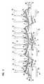
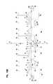
- FIG. 2is a top view of the patch panel of FIG. 1 , showing front and rear connections to cables;
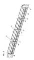
- FIG. 3is a perspective view of the patch panel of FIG. 1 , showing all of the connector modules extending parallel to the frame;
- FIG. 4is a top view of the patch panel of FIG. 3 , showing front and rear connections to cables;
- FIG. 5is a perspective view of the patch panel of FIG. 1 , showing all of the connector modules angled to the left side of the frame;
- FIG. 6is a perspective view of the patch panel of FIG. 1 , showing all of the connector modules angled to the right side of the frame;
- FIG. 7is an exploded perspective view of the patch panel of FIG. 1 ;
- FIG. 8is an exploded top view of the patch panel of FIG. 1 ;
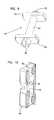
- FIG. 9is a rear perspective view of the locking pin of the patch panel of FIG. 1 ;
- FIG. 10is a perspective view of the bracket of the patch panel of FIG. 1 ;
- FIG. 11is a perspective view of the connector module of the patch panel of FIG. 1 ;
- FIG. 12is a top view of the connector module of FIG. 11 ;
- FIG. 13is a front view of the connector module of FIG. 11 ;
- FIG. 14is a side view of the connector module of FIG. 11 , an opposite side being a mirror image;
- FIG. 15is a rear view of the connector module of FIG. 11 ;
- FIG. 16is a bottom view of the connector module of FIG. 11 ;
- FIG. 17is a rear perspective view of the circuit module of the connector module of FIG. 11 ;
- FIG. 18Ais a perspective view of the patch panel of FIG. 1 , showing a vertical central reference plane;
- FIG. 18Bis a top view of the patch panel of FIG. 18A , showing the vertical central reference plane.
- Patch panel 20is shown for use in connecting telecommunications equipment.
- Patch panel 20is especially useful to cross-connect equipment through one or more of patch panels 20 or other panels.
- Patch panel 20mounts to a rack 22 of conventional construction, such as with fasteners 26 passing through holes 28 of patch panel 20 for receipt in holes 24 of rack 22 .
- Patch panel 20includes a plurality of connector jacks 30 , such as RJ45 connector jacks, on a front side 21 .
- Patch panel 20further includes a plurality of connection locations 31 , such as wire termination or connection blocks 31 mounted on an opposite rear side 23 .
- termination blocks 31include 110 type insulation displacement connectors.
- Termination blocks 31allow for connection of signal transmission cables 46 , each containing a plurality of conductive wires 48 .
- Connector jacks 30allow for connection of signal transmission patch cables or cords 44 including conductive wires and further including connector end plugs 42 .
- Circuitryelectrically connects each termination block 31 to a connector jack 30 .
- Patch panel 20includes a plurality of connector modules 32 , where each connector module 32 includes a plurality of connector jacks 30 .
- the connector modules 32 of patch panel 20are arranged in a linear array.
- Each connector module 32includes a linear array (e.g., a row) of connector jacks 30 .
- One linear array of jacks 30is shown per connector module 32 .
- Two or more arrayscould be provided.
- Alternative embodimentsinclude patch panels 20 with a single connector module 32 .
- each connector module 32may be constructed with a single connector jack 30 . As shown in FIG.
- the frame 34includes front spacers 35 that separate the modules 32 a , 32 b , 32 c and 32 d from one another.
- each connector module 32is mounted in an angled orientation relative to frame 34 .
- frame 34includes a front plane or face 36
- each connector module 32includes a front plane or face 37 where each front face 37 of the connector modules 32 is at an angle relative to front face 36 of frame 34 .
- Connector modules 32 a , 32 bare angled to the left of frame 34
- connector modules 32 c , 32 dare angled to the right.
- connector modules 32 a , 32 bare angled clockwise
- connector modules 32 c , 32 dare angled counterclockwise, as viewed from a top of frame 34 as depicted in FIG. 2 .
- the plane 37 defined by module 32 bintersects with the plane 37 defined by module 32 c at an intersection location positioned in front of the frame 34 .
- the angled relationship between the modules 32 b and 32 cprovides a generally v-shaped front connection interface defined by the rows of front connectors 30 , and a generally v-shaped rear connection interface defined by the connection locations 31 . If patch panel 20 was oriented vertically, then connector module 32 a , 32 b would be angled upwardly (or downwardly), and connector modules 32 c , 32 d would be angled downwardly (or upwardly).
- each connector module 32is about 15 degrees.
- such an angleprovides strain relief so as to help prevent cable damage and/or loss of cable performance.
- the cable positioning provided by the angled connector modules 32helps reduce the likelihood of falling below the minimum bend radius of the cable as each cable travels to other jacks or other equipment.
- Such strain reliefis advantageous over a perpendicular mounting of the connector plug relative to the cable pathway, such as illustrated in FIG. 4 .
- FIGS. 3 and 4are provided to illustrate advantageous features of patch panel 20 in accordance with the invention.
- connector modules 32are rotatable relative to frame 34 .
- each connector module 32has its front face 37 positioned generally parallel to front face 36 of frame 34 .
- a lock 40shown generally in FIGS. 1 and 2 , holds each connector module 32 to frame 34 during the termination operation. Lock 40 is releasable to allow rotation of each connector module 32 as desired. As shown in FIGS.
- connector modules 32 a , 32 bare rotated to the left, and connector modules 32 c , 32 d are rotated to the right.
- One or more connector modules 32can be left in the positions shown in FIGS. 3 and 4 , if desired. Alternatively, all the connector modules 32 can be rotated to the left as shown in FIG. 5 , or to the right as shown in FIG. 6 . To maintain the connector modules in the rotated positions, lock 40 is reactivated. If desired, one or more of the connector modules 32 and frame 34 can be constructed in a permanently angled configuration relative to front face 36 frame 34 .
- cables 44are shown as being directed away from patch panel 20 . It is to be noted that the opposite ends of cables 44 can be connected to other connector jacks 30 of patch panel 20 . Also, patch panel 20 is useable in both cross-connect systems, and in inter-connect systems, as desired. Providing strain relief so as to not fall below minimum bend radii is also an issue with fiberoptic transmission cables. The telecommunications patch panel 20 of the present invention is also useful in fiber applications with appropriately configured fiberoptic connectors.
- Lock 40is a preferred feature for patch panel 20 .
- a patch panel 20 where the lock is not activated, or a patch panel 20 where no lock is presentare both advantageous arrangements.
- each connector module 32is positionable to the left (fully or partially), to the right (fully or partially) or parallel as desired.
- the modules 32may move to a new position from an original position to provide the strain relief, as the patch cords 44 are added or changed.
- Each connector module 32includes pins 50 extending in opposite directions and defining a rotation axis 52 (see FIG. 11 ). Each rotation axis 52 is generally perpendicular to the linear array defined by connector jacks 30 . Pins 52 are received in holes 54 of frame 34 . The rotatable mounting of each connector module 32 to frame 34 could also be accomplished with a fastener passing through holes 54 .
- Frame 34generally includes a top portion 34 a and an opposing bottom portion 34 b .
- End bracket portions 34 c , 34 d on opposite ends of frame 34include rack mounting holes 28 noted above.
- End struts 34 eare continuous with end bracket portions 34 c , 34 d .
- Middle struts 34 fextend between top and bottom portions 34 a , 34 b .
- Struts 34 e , 34 f and top and bottom portions 34 a , 34 bdefine a linear array of openings for each receiving a connector module 32 .
- Holes 54 of frame 34are positioned in top and bottom portions 34 a , 34 b for holding the independently rotatable connector modules 32 about each respective rotation axis 52 .
- the rotation axes 52extend transversely relative to the linear arrays of connector jacks 30 , and also a linear array defined by the plurality of connector modules 32 .
- a plurality of locking pins 60 , and brackets 76are mounted to frame 34 .
- Each locking pin 60includes a shaft 62 , two spaced apart tabs 64 , 66 , a first tool engageable end 68 , and an opposite end 70 .
- Each tab 64 , 66has two ends extending in opposite directions. End 70 is received in hole 56 in a respective end or middle strut 34 e , 34 f .
- Tool engageable end 68is received in an aperture 80 of bracket 76 .
- Bracket 76is mounted to top and bottom portions 34 a , 34 b of frame 34 with two fasteners 82 positioned through apertures 58 . Each fastener 82 is received in a hole 78 of bracket 76 .
- brackets 76are mounted to frame 34 , locking pin 60 is rotatable between an unlocked position, and a locked position.
- the locked positionis shown in the Figures.
- the unlocked positionis where shaft 62 is rotated 90 degrees about its longitudinal axis, such as with a flathead screwdriver received in tool engageable end 68 .
- the frame 34defines a vertical central reference plane VP that bisects the frame 34 and extends in a front to rear direction. As depicted, the vertical central reference plane VP extends between the front and rear sides 21 , 23 of the frame 34 .
- Each connector module 32includes detents 84 , 86 on each end.
- Lock 40is constructed wherein tabs 64 , 66 are received in detents 84 , 86 when connector module 32 is locked in the position shown in FIG. 3 .
- When connector modules 32 are rotated out of plane 36 of frame 34only one tab 64 , 66 is received in one of detents 84 , 86 .
- Locks 40 associated with middle struts 34 f of frame 34each lock two adjacent connector modules 32 .
- Each connector module 32includes a circuit module 90 and a face plate 92 .
- Circuit module 90includes a printed circuit board 94 having a generally planar construction. As shown in FIG. 17 , pins 96 of each termination block 31 project through printed circuit board 94 and are soldered to the board. As shown in FIG. 15 , connector jacks 30 include pins 98 projecting through printed circuit board 94 , and the pins are soldered to the board. Connector jacks 30 also include two tabs 102 which snap mount to printed circuit board 94 through apertures 100 as shown in FIG. 15 .
- Printed circuit board 94includes circuit pathways to electrically link each connector jack 30 with one of the termination blocks 31 . Connector jacks 30 are shown in the Figures with the clip receiving portion of the jack facing vertically downwardly.
- Face plate 92preferably snap mounts to circuit module 90 .
- Opposite ends 110 of face plate 92include inner snaps 112 for snap fitting engagement of an edge of printed circuit board 94 . (See, for example, FIG. 12 ).
- Such a constructionallows for repair or replacement of circuit module 90 or face plate 92 , as desired.
- Face plate 92includes a central opening 108 for exposing connector jacks 30 . Face plate 92 further includes outwardly facing stops 114 on each end 110 which limit the amount of rotation of connector module 32 during use. Each stop 114 engages one edge 116 of bracket 76 so as to limit the amount of rotation of connector module to approximately plus or minus 15 degrees in the preferred embodiment. Each face plate includes a front designation strip area 120 for labeling of connector jacks 30 .
- connector jacks 30 and termination blocks 31are shown in U.S. Pat. Nos. 5,700,167; 5,674,093; 5,639,261; 5,591,045; 5,310,363; 5,299,956; and 3,611,264.
Landscapes
- Engineering & Computer Science (AREA)
- Computer Networks & Wireless Communication (AREA)
- Physics & Mathematics (AREA)
- General Physics & Mathematics (AREA)
- Optics & Photonics (AREA)
- Connector Housings Or Holding Contact Members (AREA)
- Structure Of Telephone Exchanges (AREA)
- Details Of Connecting Devices For Male And Female Coupling (AREA)
- Connections Arranged To Contact A Plurality Of Conductors (AREA)
- Shielding Devices Or Components To Electric Or Magnetic Fields (AREA)
- Coupling Device And Connection With Printed Circuit (AREA)
- Drying Of Solid Materials (AREA)
Abstract
Description
This application is a continuation of application Ser. No. 14/683,987, filed Apr. 10, 2015, now U.S. Pat. No. 9,356,384, issued May 31, 2016, which is a continuation of application Ser. No. 13/924,165, filed Jun. 21, 2013, now U.S. Pat. No. 9,033,728, which is a continuation of application Ser. No. 13/464,526, filed May 4, 2012, now U.S. Pat. No. 8,491,331, which is a continuation of application Ser. No. 13/099,022, filed May 2, 2011, now U.S. Pat. No. 8,187,027, which is a continuation of application Ser. No. 12/405,385, filed Mar. 17, 2009, now U.S. Pat. No. 7,934,948, which is a continuation of application Ser. No. 11/858,196, filed Sep. 20, 2007, now U.S. Pat. No. 7,534,135, which is a continuation of application Ser. No. 11/446,916, filed Jun. 5, 2006, now U.S. Pat. No. 7,544,090, which is a continuation of application Ser. No. 11/176,939, filed Jul. 6, 2005, now U.S. Pat. No. 7,179,119, which is a continuation of application Ser. No. 11/112,139, filed Apr. 22, 2005, now U.S. Pat. No. 7,244,144, which is a continuation of application Ser. No. 10/349,800, filed Jan. 22, 2003, now U.S. Pat. No. 6,916,199, which is a continuation of application Ser. No. 09/092,545, filed Jun. 5, 1998, now U.S. Pat. No. 6,537,106, which applications are incorporated herein by reference.
The present invention relates to a telecommunications connecting panel and, more particularly, to a cross-connect patch panel including a frame with jacks on one side and wire termination locations on an opposite side.
Local area networks and telecommunications connections often use patch panels, especially at the customer's premises to enable cross-connection between telecommunications equipment. Patch panels typically include front and rear connection locations. The rear connections are typically a more permanent type of connection, such as insulation displacement connectors to connect to copper based, twisted pair telecommunications cable. The front connections of the patch panel may include any of a variety of jacks for receipt of a plug of a patch cord or other transmission cable. The jack and plug allows fairly rapid connection and disconnection between two jacks in the same patch panel, or between one jack in the patch panel and another jack in a nearby patch panel, with the patch cord. One type of jack and plug arrangement for a patch panel is an RJ45 type connector. U.S. Pat. No. 5,639,261 is an example of a cross-connect panel including rear insulation displacement connectors, and front connector jacks for receiving plugs of patch cords.
There is an increasing need for cable management in order to protect and organize the various cables. One area where damage and/or loss of performance may occur with copper based, twisted pair cables is when excessive bending of the cable occurs. This is especially a concern as higher frequencies are used, such as category 5 and greater. Falling below minimum bend radii of the cables can adversely affect performance with the transmission of signals through the copper wire patch cords. Therefore, there is a need for patch panels which address the cable management concerns noted above.
A telecommunications patch panel according to one aspect of the invention includes a connector module, and a frame member for mounting the connector module. The connector module includes a connector jack along a front face. A rear face includes a connection location for connecting to a conductive wire or other transmission cable. Each connector module defines an axis of rotation relative to the frame member generally parallel to the front face. The connector module is positionable in one of three positions, a parallel position to the frame member, a first angled position relative to the frame member, and a second angled position relative to the frame member where the second angled position is in an opposite direction to the first angled position.
A plurality of connector modules in at least one linear array are preferably provided. Preferably, a plurality of connector jacks are provided on each connector module. The connector jacks are preferably arranged in linear arrays generally perpendicular to each axis of rotation of the connector module or modules. Locks are provided to lock the connector modules to the frame member in one of the selected positions.
According to another aspect of the present invention, a telecommunication patch panel includes a plurality of connector modules including linear arrays of connector jacks with each jack connected to a wire termination block. The connector modules are mounted to a frame member where each of the linear arrays of connector jacks is positioned at an angle relative to a front face of the frame member.
Referring now toFIGS. 1 and 2 , an embodiment of apatch panel 20 is shown for use in connecting telecommunications equipment.Patch panel 20 is especially useful to cross-connect equipment through one or more ofpatch panels 20 or other panels.Patch panel 20 mounts to arack 22 of conventional construction, such as withfasteners 26 passing throughholes 28 ofpatch panel 20 for receipt inholes 24 ofrack 22.Patch panel 20 includes a plurality of connector jacks30, such as RJ45 connector jacks, on afront side 21.Patch panel 20 further includes a plurality ofconnection locations 31, such as wire termination or connection blocks31 mounted on an oppositerear side 23. Preferably, termination blocks31 include110 type insulation displacement connectors. Termination blocks31 allow for connection ofsignal transmission cables 46, each containing a plurality ofconductive wires 48. Connector jacks30 allow for connection of signal transmission patch cables orcords 44 including conductive wires and further including connector end plugs42. Circuitry electrically connects eachtermination block 31 to aconnector jack 30.
As shown inFIGS. 1 and 2 , eachconnector module 32 is mounted in an angled orientation relative to frame34. Specifically,frame 34 includes a front plane orface 36, and eachconnector module 32 includes a front plane or face37 where eachfront face 37 of theconnector modules 32 is at an angle relative tofront face 36 offrame 34.Connector modules frame 34, andconnector modules connector modules connector modules frame 34 as depicted inFIG. 2 . As shown atFIG. 2 , theplane 37 defined bymodule 32bintersects with theplane 37 defined bymodule 32cat an intersection location positioned in front of theframe 34. As shown inFIG. 2 , the angled relationship between themodules front connectors 30, and a generally v-shaped rear connection interface defined by theconnection locations 31. Ifpatch panel 20 was oriented vertically, thenconnector module connector modules
In the illustrated preferred embodiment, the angle of displacement of eachconnector module 32 relative to frame34 is about 15 degrees. In the case ofpatch cords 44a,44bangled to the left, andpatch cords angled connector modules 32 helps reduce the likelihood of falling below the minimum bend radius of the cable as each cable travels to other jacks or other equipment. Such strain relief is advantageous over a perpendicular mounting of the connector plug relative to the cable pathway, such as illustrated inFIG. 4 .
InFIGS. 2 and 4 ,cables 44 are shown as being directed away frompatch panel 20. It is to be noted that the opposite ends ofcables 44 can be connected to other connector jacks30 ofpatch panel 20. Also,patch panel 20 is useable in both cross-connect systems, and in inter-connect systems, as desired. Providing strain relief so as to not fall below minimum bend radii is also an issue with fiberoptic transmission cables. Thetelecommunications patch panel 20 of the present invention is also useful in fiber applications with appropriately configured fiberoptic connectors.
Referring now toFIGS. 7 through 17 , additional details ofpatch panel 20 are shown. Eachconnector module 32 includespins 50 extending in opposite directions and defining a rotation axis52 (seeFIG. 11 ). Eachrotation axis 52 is generally perpendicular to the linear array defined by connector jacks30.Pins 52 are received inholes 54 offrame 34. The rotatable mounting of eachconnector module 32 to frame34 could also be accomplished with a fastener passing through holes54.
A plurality of lockingpins 60, andbrackets 76 are mounted to frame34. Each lockingpin 60 includes ashaft 62, two spaced aparttabs engageable end 68, and anopposite end 70. Eachtab End 70 is received inhole 56 in a respective end ormiddle strut engageable end 68 is received in anaperture 80 ofbracket 76.Bracket 76 is mounted to top andbottom portions frame 34 with twofasteners 82 positioned throughapertures 58. Eachfastener 82 is received in ahole 78 ofbracket 76. Oncebrackets 76 are mounted to frame34, lockingpin 60 is rotatable between an unlocked position, and a locked position. The locked position is shown in the Figures. The unlocked position is whereshaft 62 is rotated 90 degrees about its longitudinal axis, such as with a flathead screwdriver received in toolengageable end 68. Referring toFIGS. 18A and 18B , theframe 34 defines a vertical central reference plane VP that bisects theframe 34 and extends in a front to rear direction. As depicted, the vertical central reference plane VP extends between the front andrear sides frame 34.
Eachconnector module 32 includesdetents Lock 40 is constructed whereintabs detents connector module 32 is locked in the position shown inFIG. 3 . Whenconnector modules 32 are rotated out ofplane 36 offrame 34, only onetab detents lock 40 is rotated 90 degrees from the position shown in the Figures, none oftabs detents connector modules 32.Locks 40 associated withmiddle struts 34fofframe 34 each lock twoadjacent connector modules 32.
Eachconnector module 32 includes acircuit module 90 and aface plate 92.Circuit module 90 includes a printedcircuit board 94 having a generally planar construction. As shown inFIG. 17 , pins96 of eachtermination block 31 project through printedcircuit board 94 and are soldered to the board. As shown inFIG. 15 , connector jacks30 includepins 98 projecting through printedcircuit board 94, and the pins are soldered to the board. Connector jacks30 also include twotabs 102 which snap mount to printedcircuit board 94 throughapertures 100 as shown inFIG. 15 . Printedcircuit board 94 includes circuit pathways to electrically link eachconnector jack 30 with one of the termination blocks31. Connector jacks30 are shown in the Figures with the clip receiving portion of the jack facing vertically downwardly.
Examples of connector jacks30 and termination blocks31 are shown in U.S. Pat. Nos. 5,700,167; 5,674,093; 5,639,261; 5,591,045; 5,310,363; 5,299,956; and 3,611,264.
The above specification and examples provide a complete description of the manufacture and use of the invention. Since many embodiments of the invention can be made without departing from the spirit and scope of the invention, the invention resides in the claims hereinafter appended.
Claims (22)
1. A telecommunications patch panel comprising:
a frame for connection to a telecommunications rack, the frame including a front side, an opposite rear side, and a left end positioned opposite from a right end, the frame including a left mounting bracket positioned at the left end of the frame and a right mounting bracket positioned at the right end of the frame;
the frame defining a central location centered between the left and right mounting brackets of the frame;
a first plurality of left jacks being aligned along a first horizontal plane, the first plurality of left jacks being positioned between the central location and the left mounting bracket, at least some of the first plurality of left jacks being progressively recessed relative to one another in a direction along the first horizontal plane; and
a first plurality of right jacks being aligned along the horizontal plane, the first plurality of right jacks being positioned between the central location and the right mounting bracket, at least some of the first plurality of right jacks being progressively recessed relative to one another in a direction along the second horizontal plane line.
2. The telecommunications patch panel ofclaim 1 , wherein the frame includes a spacer positioned at the central location.
3. The telecommunications patch panel ofclaim 2 , wherein the spacer is generally flat.
4. The telecommunications patch panel ofclaim 1 , wherein the left and right mounting brackets are integrally formed with the frame.
5. The telecommunications patch panel ofclaim 1 , wherein the first plurality of left and right jacks together define a connection interface that is generally v-shaped when viewed from above the frame.
6. The telecommunications patch panel ofclaim 1 , wherein the first plurality of left and right jacks are configured for coupling to a copper-based telecommunications cable.
7. The telecommunications patch panel ofclaim 1 , wherein the first plurality of left and right jacks are RJ145 jacks.
8. The telecommunications patch panel ofclaim 1 , wherein the first plurality of left and right jacks are mounted to the frame via connector modules.
9. The telecommunications patch panel ofclaim 8 , wherein a first module carries the first plurality of left jacks and a second module carries the first plurality of right jacks.
10. The telecommunications patch panel ofclaim 8 , wherein the connector modules are rotatable.
11. The telecommunications patch panel ofclaim 1 , wherein each of the first plurality of left and right jacks includes at least six jacks.
12. The telecommunications patch panel ofclaim 1 , wherein at least one of the jacks from the first plurality of left jacks is connected via a first printed circuit board to rear connection locations, and wherein at least one of the jacks from the first plurality of right jacks is electrically connected via a second printed circuit board to rear connection locations.
13. The telecommunications patch panel ofclaim 12 , wherein the rear connection locations are accessible when the telecommunications patch panel is mounted to the telecommunications rack.
14. The telecommunications patch panel ofclaim 12 , wherein the rear connection locations are insulation displacement connectors.
15. The telecommunications patch panel ofclaim 1 , wherein the first plurality of left and right jacks are electrically connected via printed circuit boards to rear insulation displacement connection arrays, and wherein the rear insulation displacement connection arrays are able to be in a parallel arrangement to a corresponding portion of the frame to assist in mounting wires to the rear insulation displacement connection arrays.
16. The telecommunications patch panel ofclaim 9 , further including a second plurality of left jacks aligned along the horizontal plane, the second plurality of left jacks being positioned between the first plurality of left jacks and the left mounting bracket, and a second plurality of right jacks aligned along the horizontal plane, the second plurality of right jacks being positioned between the first plurality of right jacks and the right mounting bracket.
17. The telecommunications patch panel ofclaim 16 , wherein at least some of the second plurality of left jacks are progressively recessed relative to one another in a direction along the third horizontal plane, and at least some of the second plurality of right jacks are progressively recessed relative to one another in a direction along the horizontal plane.
18. The telecommunications patch panel ofclaim 17 , wherein a third module carries the second plurality of left jacks and a fourth module carries the second plurality of right jacks.
19. A telecommunications patch panel comprising:
a frame for connection to a telecommunications rack, the frame including a front side, an opposite rear side, and a left end positioned opposite from a right end, the frame including a left mounting bracket positioned at the left end of the frame and a right mounting bracket positioned at the right end of the frame;
the frame defining a central location centered between the left and right mounting brackets of the frame;
at least six consecutive left jacks each being progressively recessed relative to one another, the at least six consecutive left jacks comprising:
a first left jack positioned left of the central location;
a second left jack positioned left of the first left jack, the second left jack being recessed relative to the first left jack;
a third left jack positioned left of the second left jack, the third left jack being recessed relative to the second left jack;
fourth left jack positioned left of the third left jack, the fourth left jack being recessed relative to the third left jack;
as fifth left jack positioned left of the fourth left jack, the fifth left jack being recessed relative to the fourth left jack; and
a sixth left jack positioned left of the fifth left jack, the sixth left jack being recessed relative to the fifth left jack; and
at least six consecutive right jacks each being progressively recessed relative to one another, the at least six consecutive right jacks comprising:
a first right jack positioned right of the central location;
a second right jack positioned right of the first right jack, the second right jack being recessed relative to the first right jack;
a third right jack positioned right of the second right jack, the third right jack being recessed relative to the second right jack;
a fourth right jack positioned right of the third right jack the fourth right jack being recessed relative to the third right jack;
a fifth right jack positioned right of the fourth right jack, the fifth right jack being recessed relative to the fourth right jack; and
a sixth right jack positioned right of the fifth right jack, the sixth right jack being recessed relative to the fifth right jack.
20. The telecommunications patch panel ofclaim 19 , wherein at least one of the jacks from the at least six consecutive left jacks is connected via a first printed circuit board to rear connection locations, and wherein at least one of the jacks from the at last six consecutive right jacks is electrically connected via a second printed circuit hoard to rear connection locations.
21. The telecommunications patch panel ofclaim 20 , wherein the rear connection locations are accessible when the telecommunications patch panel is mounted to the telecommunications rack.
22. The telecommunications patch panel ofclaim 20 , wherein the rear connection locations are insulation displacement connectors.
Priority Applications (1)
| Application Number | Priority Date | Filing Date | Title |
|---|---|---|---|
| US15/145,288US9755381B2 (en) | 1998-06-05 | 2016-05-03 | Telecommunications patch panel with angled connector modules |
Applications Claiming Priority (12)
| Application Number | Priority Date | Filing Date | Title |
|---|---|---|---|
| US09/092,545US6537106B1 (en) | 1998-06-05 | 1998-06-05 | Telecommunications patch panel with angled connector modules |
| US10/349,800US6916199B2 (en) | 1998-06-05 | 2003-01-22 | Telecommunications patch panel with angled connector modules |
| US11/112,139US7244144B2 (en) | 1998-06-05 | 2005-04-22 | Telecommunications patch panel with angled connector modules |
| US11/176,939US7179119B2 (en) | 1998-06-05 | 2005-07-06 | Telecommunications patch panel with angled connector modules |
| US11/446,916US7544090B2 (en) | 1998-06-05 | 2006-06-05 | Telecommunications patch panel with angled connector modules |
| US11/858,196US7534135B2 (en) | 1998-06-05 | 2007-09-20 | Telecommunications patch panel with angled connector modules |
| US12/405,385US7934948B2 (en) | 1998-06-05 | 2009-03-17 | Telecommunications patch panel with angled connector modules |
| US13/099,022US8187027B2 (en) | 1998-06-05 | 2011-05-02 | Telecommunications patch panel with angled connector modules |
| US13/464,526US8491331B2 (en) | 1998-06-05 | 2012-05-04 | Telecommunications patch panel with angled connector modules |
| US13/924,165US9033728B2 (en) | 1998-06-05 | 2013-06-21 | Telecommunications patch panel with angled connector modules |
| US14/683,987US9356384B2 (en) | 1998-06-05 | 2015-04-10 | Telecommunications patch panel with angled connector modules |
| US15/145,288US9755381B2 (en) | 1998-06-05 | 2016-05-03 | Telecommunications patch panel with angled connector modules |
Related Parent Applications (1)
| Application Number | Title | Priority Date | Filing Date |
|---|---|---|---|
| US14/683,987ContinuationUS9356384B2 (en) | 1998-06-05 | 2015-04-10 | Telecommunications patch panel with angled connector modules |
Publications (2)
| Publication Number | Publication Date |
|---|---|
| US20160359282A1 US20160359282A1 (en) | 2016-12-08 |
| US9755381B2true US9755381B2 (en) | 2017-09-05 |
Family
ID=22233744
Family Applications (12)
| Application Number | Title | Priority Date | Filing Date |
|---|---|---|---|
| US09/092,545Expired - LifetimeUS6537106B1 (en) | 1998-06-05 | 1998-06-05 | Telecommunications patch panel with angled connector modules |
| US10/349,800Expired - LifetimeUS6916199B2 (en) | 1998-06-05 | 2003-01-22 | Telecommunications patch panel with angled connector modules |
| US11/112,139Expired - Fee RelatedUS7244144B2 (en) | 1998-06-05 | 2005-04-22 | Telecommunications patch panel with angled connector modules |
| US11/176,939Expired - Fee RelatedUS7179119B2 (en) | 1998-06-05 | 2005-07-06 | Telecommunications patch panel with angled connector modules |
| US11/446,916Expired - Fee RelatedUS7544090B2 (en) | 1998-06-05 | 2006-06-05 | Telecommunications patch panel with angled connector modules |
| US11/858,196Expired - Fee RelatedUS7534135B2 (en) | 1998-06-05 | 2007-09-20 | Telecommunications patch panel with angled connector modules |
| US12/405,385Expired - Fee RelatedUS7934948B2 (en) | 1998-06-05 | 2009-03-17 | Telecommunications patch panel with angled connector modules |
| US13/099,022Expired - Fee RelatedUS8187027B2 (en) | 1998-06-05 | 2011-05-02 | Telecommunications patch panel with angled connector modules |
| US13/464,526Expired - Fee RelatedUS8491331B2 (en) | 1998-06-05 | 2012-05-04 | Telecommunications patch panel with angled connector modules |
| US13/924,165Expired - Fee RelatedUS9033728B2 (en) | 1998-06-05 | 2013-06-21 | Telecommunications patch panel with angled connector modules |
| US14/683,987Expired - Fee RelatedUS9356384B2 (en) | 1998-06-05 | 2015-04-10 | Telecommunications patch panel with angled connector modules |
| US15/145,288Expired - Fee RelatedUS9755381B2 (en) | 1998-06-05 | 2016-05-03 | Telecommunications patch panel with angled connector modules |
Family Applications Before (11)
| Application Number | Title | Priority Date | Filing Date |
|---|---|---|---|
| US09/092,545Expired - LifetimeUS6537106B1 (en) | 1998-06-05 | 1998-06-05 | Telecommunications patch panel with angled connector modules |
| US10/349,800Expired - LifetimeUS6916199B2 (en) | 1998-06-05 | 2003-01-22 | Telecommunications patch panel with angled connector modules |
| US11/112,139Expired - Fee RelatedUS7244144B2 (en) | 1998-06-05 | 2005-04-22 | Telecommunications patch panel with angled connector modules |
| US11/176,939Expired - Fee RelatedUS7179119B2 (en) | 1998-06-05 | 2005-07-06 | Telecommunications patch panel with angled connector modules |
| US11/446,916Expired - Fee RelatedUS7544090B2 (en) | 1998-06-05 | 2006-06-05 | Telecommunications patch panel with angled connector modules |
| US11/858,196Expired - Fee RelatedUS7534135B2 (en) | 1998-06-05 | 2007-09-20 | Telecommunications patch panel with angled connector modules |
| US12/405,385Expired - Fee RelatedUS7934948B2 (en) | 1998-06-05 | 2009-03-17 | Telecommunications patch panel with angled connector modules |
| US13/099,022Expired - Fee RelatedUS8187027B2 (en) | 1998-06-05 | 2011-05-02 | Telecommunications patch panel with angled connector modules |
| US13/464,526Expired - Fee RelatedUS8491331B2 (en) | 1998-06-05 | 2012-05-04 | Telecommunications patch panel with angled connector modules |
| US13/924,165Expired - Fee RelatedUS9033728B2 (en) | 1998-06-05 | 2013-06-21 | Telecommunications patch panel with angled connector modules |
| US14/683,987Expired - Fee RelatedUS9356384B2 (en) | 1998-06-05 | 2015-04-10 | Telecommunications patch panel with angled connector modules |
Country Status (17)
| Country | Link |
|---|---|
| US (12) | US6537106B1 (en) |
| EP (1) | EP1084523B1 (en) |
| JP (1) | JP2002517890A (en) |
| KR (1) | KR20010052594A (en) |
| CN (2) | CN1149719C (en) |
| AR (2) | AR018435A1 (en) |
| AT (1) | ATE246851T1 (en) |
| AU (1) | AU743265B2 (en) |
| BR (1) | BR9910906A (en) |
| CA (1) | CA2334152C (en) |
| CO (1) | CO5270031A1 (en) |
| DE (1) | DE69910204T2 (en) |
| ES (1) | ES2207219T3 (en) |
| NZ (1) | NZ508811A (en) |
| PE (1) | PE20000907A1 (en) |
| TW (1) | TW423184B (en) |
| WO (1) | WO1999063628A1 (en) |
Cited By (1)
| Publication number | Priority date | Publication date | Assignee | Title |
|---|---|---|---|---|
| US20220285877A1 (en)* | 2019-08-14 | 2022-09-08 | Commscope Technologies Llc | Telecommunications patch panel with angled connector modules |
Families Citing this family (172)
| Publication number | Priority date | Publication date | Assignee | Title |
|---|---|---|---|---|
| US6537106B1 (en)* | 1998-06-05 | 2003-03-25 | Adc Telecommunications, Inc. | Telecommunications patch panel with angled connector modules |
| US6824312B2 (en)* | 2001-06-04 | 2004-11-30 | Adc Telecommunications, Inc. | Telecommunications chassis and module |
| US6866541B2 (en)* | 2001-07-26 | 2005-03-15 | Panduit Corp. | Angled patch panel with cable support bar for network cable racks |
| US6608764B2 (en)* | 2001-11-16 | 2003-08-19 | Adc Telecommunications, Inc. | Telecommunications patch panel |
| US6504726B1 (en)* | 2001-11-16 | 2003-01-07 | Adc Telecommunications, Inc. | Telecommunications patch panel |
| US6736670B2 (en) | 2001-11-16 | 2004-05-18 | Adc Telecommunications, Inc. | Angled RJ to RJ patch panel |
| US7076056B1 (en)* | 2002-01-07 | 2006-07-11 | Verizon Laboratories Inc. | Methods and apparatus for a bridge tap moderator |
| AU2003241591A1 (en)* | 2002-07-10 | 2004-02-02 | 3M Innovative Properties Company | Multiple wire cable connector |
| WO2004008582A1 (en)* | 2002-07-10 | 2004-01-22 | 3M Innovative Properties Company | Multiple wire cable connector |
| US7121888B2 (en) | 2002-07-10 | 2006-10-17 | 3M Innovative Properties Company | Multiple wire cable connector |
| GB0228929D0 (en) | 2002-12-11 | 2003-01-15 | R W Data Ltd | Structured cabling system and method |
| EP1611649A1 (en)* | 2003-03-31 | 2006-01-04 | Koninklijke Philips Electronics N.V. | Device with a physical unit with at least two operating positions |
| US20040209515A1 (en)* | 2003-04-03 | 2004-10-21 | Caveney Jack E. | High density patch panel |
| US7112090B2 (en)* | 2003-05-14 | 2006-09-26 | Panduit Corp. | High density keystone jack patch panel |
| US7094091B2 (en)* | 2003-10-27 | 2006-08-22 | Molex Incorporated | Swivel adapter |
| US6971909B2 (en)* | 2003-12-30 | 2005-12-06 | Ortronics, Inc. | Angled patch panel assembly |
| US7120347B2 (en) | 2004-01-27 | 2006-10-10 | Corning Cable Systems Llc | Multi-port optical connection terminal |
| US10680385B2 (en) | 2004-02-20 | 2020-06-09 | Commscope Technologies Llc | Methods and systems for compensating for alien crosstalk between connectors |
| US20050186838A1 (en) | 2004-02-20 | 2005-08-25 | Debenedictis Damon | Methods and systems for positioning connectors to minimize alien crosstalk |
| US7311550B2 (en) | 2004-02-20 | 2007-12-25 | Adc Telecommunications, Inc. | Methods and systems for positioning connectors to minimize alien crosstalk |
| US7232340B2 (en) | 2004-02-20 | 2007-06-19 | Adc Incorporated | Methods and systems for minimizing alien crosstalk between connectors |
| US20050221678A1 (en) | 2004-02-20 | 2005-10-06 | Hammond Bernard Jr | Methods and systems for compensating for alien crosstalk between connectors |
| US7187766B2 (en) | 2004-02-20 | 2007-03-06 | Adc Incorporated | Methods and systems for compensating for alien crosstalk between connectors |
| US7383820B2 (en)* | 2004-03-19 | 2008-06-10 | Ford Global Technologies, Llc | Electromechanical valve timing during a start |
| US7200929B2 (en)* | 2004-03-31 | 2007-04-10 | Adc Telecommunications, Inc. | Patch panel with modules |
| US7362590B2 (en)* | 2004-03-31 | 2008-04-22 | Adc Telecommunications, Inc. | Patch panel with modules |
| US7220145B2 (en)* | 2004-04-14 | 2007-05-22 | Tyco Electronics Corporation | Patch panel system |
| AU158235S (en) | 2004-06-16 | 2005-08-03 | Krone Australia Holdings Pty Ltd | Patch panel |
| US7488202B2 (en)* | 2004-07-28 | 2009-02-10 | American Power Conversion Corporation | Multiport cabling system and method |
| US20060067068A1 (en)* | 2004-09-27 | 2006-03-30 | Petersen Cyle D | Digital cross-connect system and rack arrangement |
| US7201607B2 (en)* | 2005-02-24 | 2007-04-10 | Tyco Electronics Corporation | Stackable modular general purpose rectangular connector |
| US7094095B1 (en)* | 2005-02-25 | 2006-08-22 | Panduit Corp. | Stair-stepped angled patch panel |
| US20060194565A1 (en)* | 2005-02-28 | 2006-08-31 | Smith David R | Super block |
| US7194181B2 (en) | 2005-03-31 | 2007-03-20 | Adc Telecommunications, Inc. | Adapter block including connector storage |
| US7091418B1 (en)* | 2005-04-01 | 2006-08-15 | Adc Telecommunications, Inc. | Cable management bar and patch panel |
| DK200501216A (en)* | 2005-08-31 | 2007-03-01 | Schneider Electric Danmark As | Communication signal distribution module |
| USD542240S1 (en) | 2005-09-08 | 2007-05-08 | Leviton Manufacturing Co., Inc. | Patch panel |
| US7300308B2 (en)* | 2005-09-09 | 2007-11-27 | Leviton Manufacturing Co., Inc. | Patch panel |
| JP2007080357A (en)* | 2005-09-13 | 2007-03-29 | Toshiba Corp | Information storage medium, information reproduction method, and information reproduction apparatus |
| US7320600B2 (en)* | 2005-10-25 | 2008-01-22 | Research In Motion Limited | Device opener and vibration mechanism |
| US7294024B2 (en) | 2006-01-06 | 2007-11-13 | Adc Telecommunications, Inc. | Methods and systems for minimizing alien crosstalk between connectors |
| US7591676B2 (en)* | 2006-02-03 | 2009-09-22 | Ortronics, Inc. | Arcuate patch panel assembly |
| US7393243B2 (en)* | 2006-02-10 | 2008-07-01 | Panduit Corp. | Angled patch panel with pitched connector alignment |
| US7354289B2 (en)* | 2006-05-30 | 2008-04-08 | Agilent Technologies, Inc. | Positive locking push-on precision 3.5 mm or 2.4 mm connector for an oscilloscope probe |
| US7357667B2 (en)* | 2006-06-22 | 2008-04-15 | Adc Telecommunications, Inc. | Telecommunications patch |
| US7950531B2 (en)* | 2006-06-23 | 2011-05-31 | Adc Gmbh | Mounting arrangement for a standard telecommunications panel |
| US7343078B2 (en)* | 2006-06-29 | 2008-03-11 | Commscope Solutions Properties, Llc | Patch panels with communications connectors that are rotatable about a vertical axis |
| US20080009183A1 (en)* | 2006-07-06 | 2008-01-10 | Ching-Li Wu | High density module connector |
| US7689089B2 (en) | 2006-10-11 | 2010-03-30 | Panduit Corp. | Release latch for pre-terminated cassette |
| US7455548B2 (en)* | 2006-10-19 | 2008-11-25 | Adc Telecommunication, Inc. | Rotatable connector modules with inverted jacks |
| US7335056B1 (en)* | 2006-10-19 | 2008-02-26 | Adc Telecommunications, Inc. | RJ to RJ swing panel |
| US7488205B2 (en)* | 2006-12-13 | 2009-02-10 | Commscope, Inc. Of North Carolina | Fixed angled patch panel |
| US7493002B2 (en)* | 2007-01-19 | 2009-02-17 | Adc Telecommunications, Inc. | Fiber optic adapter cassette and panel |
| US7499622B2 (en)* | 2007-02-28 | 2009-03-03 | Corning Cable Systems Llc | Fiber optic drop terminals for multiple dwelling units |
| US20080222312A1 (en)* | 2007-03-09 | 2008-09-11 | Westell Technologies, Inc. | Apparatus and method for optimizing use of a modem jack |
| TWI329397B (en)* | 2007-04-17 | 2010-08-21 | Delta Electronics Inc | Fan and plug thereof |
| DE202007005870U1 (en) | 2007-04-23 | 2007-07-12 | CCS Technology, Inc., Wilmington | Device for receiving connectors |
| CN101295899B (en)* | 2007-04-29 | 2012-10-10 | 台达电子工业股份有限公司 | Fan and plug thereof |
| EP1993295A1 (en)* | 2007-05-14 | 2008-11-19 | 3M Innovative Properties Company | Telecommunication assembly with an inner frame and an outer frame |
| US7787260B2 (en) | 2007-07-09 | 2010-08-31 | Adc Telecommunications, Inc. | Cable management arrangement for a telecommunications cabinet |
| MX2010001515A (en)* | 2007-08-09 | 2010-03-10 | Belden Cdt Canada Inc | TELESCOPIC CONNECTOR ASSEMBLY. |
| GB2451849A (en)* | 2007-08-14 | 2009-02-18 | Brand Rex Ltd | Patch panel having angled jacks |
| US20090051558A1 (en)* | 2007-08-20 | 2009-02-26 | Tellabs Bedford, Inc. | Method and apparatus for providing optical indications about a state of a circuit |
| SG150428A1 (en) | 2007-09-06 | 2009-03-30 | Adc Gmbh | Telecommunications patch panel |
| US7740409B2 (en) | 2007-09-19 | 2010-06-22 | Corning Cable Systems Llc | Multi-port optical connection terminal |
| US8463091B2 (en) | 2007-10-15 | 2013-06-11 | Telescent Inc. | Methods to reconfigure all-fiber optical cross-connects |
| CA2710297A1 (en)* | 2007-12-21 | 2009-07-02 | Belden Cdt Canada Inc. | Patch panel with angled module |
| US20090227123A1 (en)* | 2008-03-07 | 2009-09-10 | Tellabs Bedford, Inc. | Connectorized alarm cross connect panel |
| US8452148B2 (en) | 2008-08-29 | 2013-05-28 | Corning Cable Systems Llc | Independently translatable modules and fiber optic equipment trays in fiber optic equipment |
| US11294136B2 (en) | 2008-08-29 | 2022-04-05 | Corning Optical Communications LLC | High density and bandwidth fiber optic apparatuses and related equipment and methods |
| US8290330B2 (en)* | 2008-09-05 | 2012-10-16 | Adc Gmbh | Patch panel assembly |
| US7876995B2 (en)* | 2008-10-29 | 2011-01-25 | Commscope, Inc. Of North Carolina | Telecommunications patching systems with obliquely-angled patching modules |
| US20110217857A1 (en)* | 2008-11-12 | 2011-09-08 | Adc Gmbh | Cradle for fastening a terminal block to a mounting frame and arrangement for earthing a terminal block |
| US8428418B2 (en)* | 2008-12-09 | 2013-04-23 | Adc Telecommunications, Inc. | Fiber optic adapter plate and cassette |
| US7762839B2 (en)* | 2008-12-22 | 2010-07-27 | Surtec Industries, Inc. | Patch panel assembly |
| US8145442B2 (en)* | 2009-01-30 | 2012-03-27 | Synopsys, Inc. | Fast and accurate estimation of gate output loading |
| EP2221932B1 (en) | 2009-02-24 | 2011-11-16 | CCS Technology Inc. | Holding device for a cable or an assembly for use with a cable |
| AU2009200824A1 (en)* | 2009-03-03 | 2010-09-23 | Tyco Electronics Services Gmbh | Consolidation point enclosure |
| US7874869B2 (en)* | 2009-03-26 | 2011-01-25 | Cisco Technology, Inc. | Reconfigurable patch panel |
| US7922522B2 (en)* | 2009-04-02 | 2011-04-12 | Fluke Corporation | Instrument having oblique mounted terminal posts |
| CN102334237B (en)* | 2009-04-02 | 2015-05-13 | 西蒙公司 | Telecommunications patch panel |
| TWI376998B (en)* | 2009-04-03 | 2012-11-11 | John Peng | Structure of network patch panel and patch panel |
| US7867022B2 (en)* | 2009-04-08 | 2011-01-11 | Tyco Electronics Corporation | Brackets and receptacle assemblies with angled ports |
| US8075348B2 (en) | 2009-04-23 | 2011-12-13 | Commscope Inc. Of North Carolina | Assembly and system of datacommunication cables and connectors |
| CN102428396B (en) | 2009-05-19 | 2014-10-29 | 住友电气工业株式会社 | Splitter module |
| US9075216B2 (en) | 2009-05-21 | 2015-07-07 | Corning Cable Systems Llc | Fiber optic housings configured to accommodate fiber optic modules/cassettes and fiber optic panels, and related components and methods |
| AU2009202010A1 (en)* | 2009-05-21 | 2010-12-09 | Adc Gmbh | Chassis for coupling a stack of two or more telecommunications modules to a front side of a racking system |
| US8744228B2 (en)* | 2009-05-22 | 2014-06-03 | Commscope, Inc. Of North Carolina | Telecommunications patching system with cable management system and related cable management equipment |
| EP2443497B1 (en) | 2009-06-19 | 2020-03-04 | Corning Cable Systems LLC | High density and bandwidth fiber optic apparatus |
| TWI416188B (en)* | 2009-12-31 | 2013-11-21 | Emcom Technology Inc | Foldable supporter for electric cable |
| US8992099B2 (en) | 2010-02-04 | 2015-03-31 | Corning Cable Systems Llc | Optical interface cards, assemblies, and related methods, suited for installation and use in antenna system equipment |
| US8406597B2 (en)* | 2010-02-16 | 2013-03-26 | Commscope, Inc. Of North Carolina | Intelligent fiber optic adapter mounting structures that receive and correctly position multiple types of fiber optic adapters and related adapter collars and bulkheads |
| US8913866B2 (en) | 2010-03-26 | 2014-12-16 | Corning Cable Systems Llc | Movable adapter panel |
| CA2796221C (en) | 2010-04-16 | 2018-02-13 | Ccs Technology, Inc. | Sealing and strain relief device for data cables |
| US9519118B2 (en) | 2010-04-30 | 2016-12-13 | Corning Optical Communications LLC | Removable fiber management sections for fiber optic housings, and related components and methods |
| US8879881B2 (en) | 2010-04-30 | 2014-11-04 | Corning Cable Systems Llc | Rotatable routing guide and assembly |
| US9075217B2 (en) | 2010-04-30 | 2015-07-07 | Corning Cable Systems Llc | Apparatuses and related components and methods for expanding capacity of fiber optic housings |
| US9377597B2 (en)* | 2010-06-02 | 2016-06-28 | Commscope Technologies Llc | Aggregator for a switch rack system |
| EP2400775B1 (en)* | 2010-06-22 | 2014-01-15 | 3M Innovative Properties Co. | Support structure for telecommunication jacks |
| EP2586100A1 (en) | 2010-06-24 | 2013-05-01 | CommScope, Inc. of North Carolina | Datacommunications modules, cable-connector assemblies and components therefor |
| US8600208B2 (en) | 2010-08-24 | 2013-12-03 | Adc Telecommunications, Inc. | Fiber optic telecommunications module |
| US9279951B2 (en) | 2010-10-27 | 2016-03-08 | Corning Cable Systems Llc | Fiber optic module for limited space applications having a partially sealed module sub-assembly |
| WO2012058391A1 (en) | 2010-10-28 | 2012-05-03 | Corning Cable Systems Llc | Impact resistant fiber optic enclosures and related methods |
| US9116324B2 (en) | 2010-10-29 | 2015-08-25 | Corning Cable Systems Llc | Stacked fiber optic modules and fiber optic equipment configured to support stacked fiber optic modules |
| EP2456017B1 (en)* | 2010-11-18 | 2014-06-04 | Siemens Aktiengesellschaft | Connector device for electronic components in automation systems |
| JP5548592B2 (en)* | 2010-11-19 | 2014-07-16 | 本田技研工業株式会社 | Cogeneration equipment |
| CA2819235C (en) | 2010-11-30 | 2018-01-16 | Corning Cable Systems Llc | Fiber device holder and strain relief device |
| JP2012128783A (en)* | 2010-12-17 | 2012-07-05 | Sony Corp | Information processor |
| WO2012106510A2 (en) | 2011-02-02 | 2012-08-09 | Corning Cable Systems Llc | Dense fiber optic connector assemblies and related connectors and cables suitable for establishing optical connections for optical backplanes in equipment racks |
| US8935849B2 (en) | 2011-03-10 | 2015-01-20 | Fci Americas Technology Llc | Method for mounting a cable connector onto a panel |
| DE102011006195A1 (en)* | 2011-03-28 | 2012-10-04 | Robert Bosch Gmbh | Modular electrical connector assembly |
| US9008485B2 (en) | 2011-05-09 | 2015-04-14 | Corning Cable Systems Llc | Attachment mechanisms employed to attach a rear housing section to a fiber optic housing, and related assemblies and methods |
| KR101219952B1 (en)* | 2011-06-24 | 2013-01-21 | 현대자동차주식회사 | Wire connecting device for hybrid vehicle |
| AU2012275598A1 (en) | 2011-06-30 | 2014-01-16 | Corning Optical Communications LLC | Fiber optic equipment assemblies employing non-U-width-sized housings and related methods |
| US8953924B2 (en) | 2011-09-02 | 2015-02-10 | Corning Cable Systems Llc | Removable strain relief brackets for securing fiber optic cables and/or optical fibers to fiber optic equipment, and related assemblies and methods |
| US9417418B2 (en) | 2011-09-12 | 2016-08-16 | Commscope Technologies Llc | Flexible lensed optical interconnect device for signal distribution |
| RU2611105C2 (en) | 2011-10-07 | 2017-02-21 | Адс Телекоммьюникейшнз, Инк. | Fibre-optic cartridge, system and method |
| US9069151B2 (en) | 2011-10-26 | 2015-06-30 | Corning Cable Systems Llc | Composite cable breakout assembly |
| US8585437B2 (en) | 2011-11-10 | 2013-11-19 | Jyh Eng Technology Co., Ltd. | Angle panel |
| DE202011052046U1 (en) | 2011-11-21 | 2012-01-27 | Jyh Eng Technology Co., Ltd. | Angle Steckfeld |
| US9038832B2 (en)* | 2011-11-30 | 2015-05-26 | Corning Cable Systems Llc | Adapter panel support assembly |
| US9215814B2 (en)* | 2011-12-23 | 2015-12-15 | Coriant Operations, Inc. | Electronics assembly divider plate |
| WO2013112858A1 (en)* | 2012-01-27 | 2013-08-01 | Go!Foton Holdings, Inc. | Patch panel assembly |
| US8873926B2 (en) | 2012-04-26 | 2014-10-28 | Corning Cable Systems Llc | Fiber optic enclosures employing clamping assemblies for strain relief of cables, and related assemblies and methods |
| CN202600189U (en)* | 2012-05-31 | 2012-12-12 | 泰科电子(上海)有限公司 | Adapter assembly and connector assembly |
| US9420715B2 (en)* | 2012-06-07 | 2016-08-16 | Intal Tech Ltd. | Electrononic equipment building blocks for rack mounting |
| KR20130143339A (en)* | 2012-06-21 | 2013-12-31 | 삼성전자주식회사 | Angle adjustable ear jack module |
| US9250409B2 (en) | 2012-07-02 | 2016-02-02 | Corning Cable Systems Llc | Fiber-optic-module trays and drawers for fiber-optic equipment |
| US8894438B2 (en) | 2012-07-11 | 2014-11-25 | Tyco Electronics Corporation | Receptacle assembly having angled receptacle guide frames |
| US9042702B2 (en) | 2012-09-18 | 2015-05-26 | Corning Cable Systems Llc | Platforms and systems for fiber optic cable attachment |
| NZ706687A (en) | 2012-09-28 | 2017-09-29 | Adc Telecommunications Inc | Fiber optic cassette |
| US9146374B2 (en) | 2012-09-28 | 2015-09-29 | Adc Telecommunications, Inc. | Rapid deployment packaging for optical fiber |
| US9223094B2 (en) | 2012-10-05 | 2015-12-29 | Tyco Electronics Nederland Bv | Flexible optical circuit, cassettes, and methods |
| ES2551077T3 (en) | 2012-10-26 | 2015-11-16 | Ccs Technology, Inc. | Fiber optic management unit and fiber optic distribution device |
| US8747150B1 (en)* | 2012-12-24 | 2014-06-10 | Jyh Eng Technology Co., Ltd. | Multidirectional modular jack and face panel mounting structure |
| US8985862B2 (en) | 2013-02-28 | 2015-03-24 | Corning Cable Systems Llc | High-density multi-fiber adapter housings |
| US9435975B2 (en) | 2013-03-15 | 2016-09-06 | Commscope Technologies Llc | Modular high density telecommunications frame and chassis system |
| CN105359549B (en)* | 2013-04-30 | 2018-12-25 | 泰科电子安普西班牙公司 | Patch panel system and for being fixed to jack module thereon |
| US9247319B2 (en)* | 2013-06-17 | 2016-01-26 | Cisco Technology, Inc. | Panel assembly |
| CN104283083B (en)* | 2013-07-05 | 2016-04-06 | 好庆科技企业股份有限公司 | Connector rotating frame, connector and connector base board device |
| US9326418B2 (en) | 2014-07-16 | 2016-04-26 | Knubox, Llc | Unified network connection device |
| US10423693B2 (en)* | 2014-09-15 | 2019-09-24 | Autodesk, Inc. | Parallel processing using a bottom up approach |
| US9885845B2 (en)* | 2015-01-15 | 2018-02-06 | Commscope, Inc. Of North Carolina | Module and assembly for fiber optic interconnections |
| US9640898B1 (en)* | 2015-02-11 | 2017-05-02 | NetSuite Inc. | System and method for efficient coupling of cabling in a multi-cable rack-mounted environment |
| US10151890B2 (en) | 2015-03-18 | 2018-12-11 | Leviton Manufacturing Co., Inc. | Data communication port insert configurable with indicia to customize data communication station labeling and identification |
| US10732372B2 (en) | 2015-04-24 | 2020-08-04 | Commscope, Inc. Of North Carolina | Shelf for communications rack or cabinet |
| US9397450B1 (en)* | 2015-06-12 | 2016-07-19 | Amphenol Corporation | Electrical connector with port light indicator |
| US9794195B1 (en)* | 2015-06-26 | 2017-10-17 | Amazon Technologies, Inc. | Communication device with receded ports |
| CN106410535B (en)* | 2015-07-29 | 2020-10-02 | 福特环球技术公司 | Base device of electric socket and vehicle interior assembly |
| US9888603B1 (en)* | 2016-02-29 | 2018-02-06 | EMC IP Holding Co. LLC | Slider arm assembly for cable carrier |
| US10291969B2 (en) | 2017-02-14 | 2019-05-14 | Go!Foton Holdings, Inc. | Rear cable management |
| US10063021B1 (en)* | 2017-04-28 | 2018-08-28 | Leviton Manufacturing Co., Inc. | Connector assembly with ball joint interface |
| US20190008075A1 (en)* | 2017-06-30 | 2019-01-03 | Quanta Computer Inc. | Arc shape front panel |
| US10222562B1 (en)* | 2017-09-07 | 2019-03-05 | Quanta Computer Inc. | Flexible connector interface |
| US11409068B2 (en) | 2017-10-02 | 2022-08-09 | Commscope Technologies Llc | Fiber optic circuit and preparation method |
| DE102017124632A1 (en)* | 2017-10-23 | 2019-04-25 | Harting Electric Gmbh & Co. Kg | Holding frame for an industrial connector |
| US10571640B2 (en) | 2018-06-22 | 2020-02-25 | Panduit Corp. | Cassette adapter and method of installation |
| US11052837B2 (en)* | 2018-09-28 | 2021-07-06 | Yazaki Corporation | Wire harness |
| US10804663B2 (en)* | 2019-02-07 | 2020-10-13 | Steve Cheng | Swivel pivot connector adapter |
| US11417992B2 (en) | 2019-06-12 | 2022-08-16 | Ortronics, Inc. | Modular edge patching system |
| LU101419B1 (en) | 2019-09-27 | 2021-03-31 | Phoenix Contact Gmbh & Co | Lockable connection module |
| CN112652913A (en)* | 2019-10-10 | 2021-04-13 | 康普技术有限责任公司 | Modular telecommunications panel system and telecommunications module |
| CN112652897A (en) | 2019-10-10 | 2021-04-13 | 康普技术有限责任公司 | Modular telecommunications panel and modular telecommunications system |
| CN112839265A (en) | 2019-11-22 | 2021-05-25 | 康普技术有限责任公司 | Communication Patch Panels and Communication Rack Systems |
| CN110799015B (en)* | 2019-11-25 | 2021-01-29 | 中航光电科技股份有限公司 | A special-shaped front panel assembly |
| US12339511B2 (en) | 2020-03-31 | 2025-06-24 | Commscope Technologies Llc | Fiber optic cable management systems and methods |
| EP3905710B1 (en)* | 2020-04-28 | 2025-03-12 | Reichle & De-Massari AG | Cable management system |
| EP3971622A1 (en) | 2020-07-02 | 2022-03-23 | Go!Foton Holdings, Inc. | Intelligent optical switch |
| US11516558B2 (en) | 2020-09-10 | 2022-11-29 | Ciena Corporation | Angled faceplates for a network element |
| DE102020133213A1 (en) | 2020-11-27 | 2022-06-02 | Liebherr-Hausgeräte Ochsenhausen GmbH | Plug holder for a refrigerator and/or freezer |
| EP4533814A1 (en) | 2022-05-26 | 2025-04-09 | CommScope Technologies LLC | Recessed power cable transition panel |
| USD1073626S1 (en) | 2022-10-31 | 2025-05-06 | Commscope Technologies Llc | Recessed power cable transition panel |
Citations (86)
| Publication number | Priority date | Publication date | Assignee | Title |
|---|---|---|---|---|
| US1616114A (en) | 1925-03-30 | 1927-02-01 | Western Electric Co | Telephone jack |
| US2317450A (en) | 1942-04-25 | 1943-04-27 | Cook Electric Co | Terminal box |
| US2427349A (en) | 1944-11-16 | 1947-09-16 | Earl S Boynton | Electrical receptacle |
| US3337059A (en) | 1965-10-13 | 1967-08-22 | Hoy David P Le | Disc holder |
| US3611264A (en) | 1968-12-27 | 1971-10-05 | Bell Telephone Labor Inc | Wire connecting blocks |
| US3915541A (en) | 1972-10-18 | 1975-10-28 | Philips Corp | Junction box |
| US3953100A (en) | 1975-04-04 | 1976-04-27 | Liebert Corporation | Infrared lamp holder |
| US3958850A (en) | 1972-04-28 | 1976-05-25 | Bunker Ramo Corporation | Method and apparatus for connecting multi-conductor cables |
| US4085992A (en) | 1974-03-06 | 1978-04-25 | Bunker Ramo Corporation | Method and apparatus for connecting multi-conductor cables |
| USD247965S (en) | 1976-05-10 | 1978-05-23 | Gray Steven M | Telephone answering service console |
| US4131330A (en) | 1976-03-31 | 1978-12-26 | Bunker Ramo Corporation | Mounting device for electrical connectors |
| USD271965S (en) | 1981-03-06 | 1983-12-27 | Hollfelder Thomas A | Telephone terminal block or similar article |
| US4536052A (en) | 1984-02-09 | 1985-08-20 | At&T Information Systems | Modular cross-connect panel |
| US4747020A (en) | 1986-05-16 | 1988-05-24 | Adc Telecommunications, Inc. | Wire distribution apparatus |
| US4815104A (en) | 1988-01-11 | 1989-03-21 | Telect, Inc. | Digital telecommunications network, cross-connect module |
| US4824196A (en) | 1987-05-26 | 1989-04-25 | Minnesota Mining And Manufacturing Company | Optical fiber distribution panel |
| US4995688A (en) | 1989-07-31 | 1991-02-26 | Adc Telecommunications, Inc. | Optical fiber distribution frame |
| US5000703A (en) | 1989-01-26 | 1991-03-19 | Krone Aktiengesellschaft | Connector bank |
| US5011257A (en) | 1988-06-29 | 1991-04-30 | British Telecommunications Public Limited Company | Optical fiber patch panel |
| US5127082A (en) | 1991-03-22 | 1992-06-30 | The Siemon Company | Fiber optic patch panel |
| US5129842A (en) | 1991-04-08 | 1992-07-14 | Digital Equipment Corporation | Modular patch panel |
| US5139445A (en) | 1990-12-07 | 1992-08-18 | The Siemon Company | Modular test adapter |
| US5178554A (en) | 1990-10-26 | 1993-01-12 | The Siemon Company | Modular jack patching device |
| US5214735A (en) | 1992-04-06 | 1993-05-25 | Adc Telecommunications, Inc. | Fiber optic connector retainer |
| US5238426A (en) | 1992-06-11 | 1993-08-24 | At&T Bell Laboratories | Universal patch panel for communications use in buildings |
| US5299956A (en) | 1992-03-23 | 1994-04-05 | Superior Modular Products, Inc. | Low cross talk electrical connector system |
| US5302140A (en) | 1993-04-02 | 1994-04-12 | At&T Bell Laboratories | Connector with mounting collar for use in universal patch panel systems |
| US5303519A (en) | 1991-09-16 | 1994-04-19 | E. L. Mustee & Sons, Inc. | Shower stall with molded angle panel |
| US5370541A (en) | 1993-01-25 | 1994-12-06 | Minnesota Mining And Manufacturing Company | Repositionable termination module |
| US5370553A (en) | 1993-03-12 | 1994-12-06 | At&T Corp. | Adjustable terminations in equipment housing for cables |
| US5412751A (en) | 1993-08-31 | 1995-05-02 | The Siemon Company | Retrofittable multimedia patch management system |
| US5415296A (en) | 1993-07-13 | 1995-05-16 | Wright; Robert K. | Display system for use with jewel type compact disc packaging containers, and method of use |
| USD367037S (en) | 1995-01-17 | 1996-02-13 | Woods Industries, Inc. | Electrical outlet unit |
| US5530954A (en) | 1995-01-13 | 1996-06-25 | Telect, Inc. | Telecommunication fiber optic patch panel shelf assembly |
| EP0736937A1 (en) | 1995-04-04 | 1996-10-09 | Atreus Enterprises Limited | Electrical accessory |
| US5575665A (en) | 1995-12-01 | 1996-11-19 | Superior Modular Products Incorporated | Patch panel with hinged tie bar |
| US5591045A (en) | 1995-05-18 | 1997-01-07 | The Whitaker Corporation | Wire connecting system |
| US5639261A (en) | 1994-12-23 | 1997-06-17 | Lucent Technologies Inc. | Modular cross-connect system |
| US5645449A (en) | 1995-02-21 | 1997-07-08 | The Whitaker Corporation | Low profile mixed media information outlet |
| US5659650A (en) | 1995-09-26 | 1997-08-19 | Lucent Technologies Inc. | Hinged faceplate |
| US5674093A (en) | 1996-07-23 | 1997-10-07 | Superior Modular Process Incorporated | Reduced cross talk electrical connector |
| US5676566A (en) | 1994-11-04 | 1997-10-14 | The Siemon Company | Multimedia outlet |
| US5701380A (en) | 1996-06-24 | 1997-12-23 | Telect, Inc. | Fiber optic module for high density supply of patching and splicing |
| US5700167A (en) | 1996-09-06 | 1997-12-23 | Lucent Technologies | Connector cross-talk compensation |
| US5721394A (en) | 1996-07-12 | 1998-02-24 | Mulks; Robert | Flush mount multiport connection box |
| US5734776A (en) | 1996-08-28 | 1998-03-31 | Adc Telecommunications, Inc. | Outside plant cross-connect apparatus |
| US5735714A (en) | 1995-04-06 | 1998-04-07 | Ortronics Inc. | Information management outlet module and assembly providing protection to exposed cabling |
| US5778130A (en) | 1996-12-31 | 1998-07-07 | Siecor Corporation | Optical fiber connector housing |
| US5788087A (en) | 1996-03-18 | 1998-08-04 | Ortronics, Inc. | Hinged wire management panel assembly |
| US5836786A (en) | 1996-05-21 | 1998-11-17 | The Whitaker Corporation | Patch panel having snap together construction |
| US5888079A (en) | 1997-10-16 | 1999-03-30 | Eugene A Norden | Telephone service panels |
| US5892870A (en) | 1995-11-16 | 1999-04-06 | Fiber Connections Inc. | Fibre optic cable connector |
| US5903698A (en) | 1997-04-11 | 1999-05-11 | Wiltron Company | Fiber optic connection assembly |
| US5921402A (en) | 1998-04-27 | 1999-07-13 | Systems Manufacturing Corporation | Cable management track system |
| US5944535A (en) | 1997-02-04 | 1999-08-31 | Hubbell Incorporated | Interface panel system for networks |
| US5945633A (en) | 1996-05-23 | 1999-08-31 | The Siemon Company | Rack mountable cable distribution enclosure having an angled adapter plate bracket |
| US5956449A (en) | 1997-02-26 | 1999-09-21 | Nec Corporation | Structure for mounting an optical circuit |
| US5969294A (en) | 1997-12-31 | 1999-10-19 | Siecor Operations, Llc | Fiber optic connector cabinet with rotatably mounted adapter panels |
| US5967836A (en) | 1997-06-26 | 1999-10-19 | Bailey; Ronald I. | Swivel electrical receptacle |
| US5984720A (en) | 1997-10-17 | 1999-11-16 | Hubbell Incorporated | Angled interconnect panel assembly for telecommunications applications |
| US5993251A (en) | 1997-12-22 | 1999-11-30 | Nortel Networks Corporation | Staggered Faceplate |
| US6146192A (en) | 1999-03-31 | 2000-11-14 | Adc Telecommunications, Inc. | Bulkhead connector system including angled adapter |
| US6200159B1 (en) | 1999-10-15 | 2001-03-13 | Jonie Chou | Multi-deck electric outlet assembly |
| US6208796B1 (en) | 1998-07-21 | 2001-03-27 | Adc Telecommunications, Inc. | Fiber optic module |
| US6236795B1 (en) | 1999-06-07 | 2001-05-22 | E. Walter Rodgers | High-density fiber optic cable distribution frame |
| US6240234B1 (en) | 1999-12-01 | 2001-05-29 | Cisco Technology, Inc. | Mechanism for securing cables |
| US6242698B1 (en) | 1998-12-08 | 2001-06-05 | Avaya Technology Corporation | Interchangeable adapter face plates |
| US6259852B1 (en) | 2000-01-05 | 2001-07-10 | Avaya Technology Corp. | Fiber optic pedestal |
| US6293707B1 (en) | 1999-02-19 | 2001-09-25 | Lucent Technologies Inc. | Patch panel with pivoting bracket assembly |
| US6350148B1 (en) | 1999-02-10 | 2002-02-26 | Avaya Technology Corp. | Method and device for detecting the presence of a patch cord connector in a telecommunications patch system |
| US6468112B1 (en) | 1999-01-11 | 2002-10-22 | Adc Telecommunications, Inc. | Vertical cable management system with ribcage structure |
| US6497578B1 (en) | 2001-04-11 | 2002-12-24 | Nortel Networks Limited | Method and apparatus to increase cable connector density in equipment |
| US6522548B1 (en) | 2001-07-27 | 2003-02-18 | Scientific-Atlanta, Inc. | Faceted extended interface module |
| US6537106B1 (en) | 1998-06-05 | 2003-03-25 | Adc Telecommunications, Inc. | Telecommunications patch panel with angled connector modules |
| US6565260B2 (en) | 2001-10-19 | 2003-05-20 | Axe, Inc. | High-connector density interface plate |
| US6600106B2 (en) | 2001-07-11 | 2003-07-29 | Adc Telecommunications, Inc. | Cable management bar and patch panel |
| US6614978B1 (en) | 2000-06-02 | 2003-09-02 | Panduit Corp. | Slack cable management system |
| US6692284B1 (en) | 1999-02-26 | 2004-02-17 | Nnb Electronic Technology Pte. Ltd. | Electrical socket and plug |
| US6711339B2 (en) | 2002-05-31 | 2004-03-23 | Adc Telecommunications, Inc. | Fiber management module with cable storage |
| US20040209515A1 (en) | 2003-04-03 | 2004-10-21 | Caveney Jack E. | High density patch panel |
| US6866541B2 (en) | 2001-07-26 | 2005-03-15 | Panduit Corp. | Angled patch panel with cable support bar for network cable racks |
| US6902429B1 (en) | 2004-07-29 | 2005-06-07 | Frederick A. Brooks | Multiple electrical outlet device |
| US20050142910A1 (en) | 2003-12-30 | 2005-06-30 | Levesque Stewart A. | Angled patch panel assembly |
| US6916213B2 (en) | 2000-12-01 | 2005-07-12 | Abb Oy | Connection base |
| US20050233635A1 (en) | 2004-04-14 | 2005-10-20 | Sam Denovich | Patch panel system |
| US20050233647A1 (en) | 2004-04-14 | 2005-10-20 | Sam Denovich | Non-orthogonal cable management system |
Family Cites Families (4)
| Publication number | Priority date | Publication date | Assignee | Title |
|---|---|---|---|---|
| JP2562202B2 (en)* | 1989-04-15 | 1996-12-11 | 松下電工株式会社 | Outlet |
| US5345633A (en)* | 1993-04-13 | 1994-09-13 | Robert Harnish | Cushion with internal storage pouch |
| US5370533A (en)* | 1993-11-08 | 1994-12-06 | Bushnell; Raymond B. | Dental impression tray assembly and method of taking impressions |
| CN2240796Y (en)* | 1994-12-27 | 1996-11-20 | 盛超 | Composite socket |
- 1998
- 1998-06-05USUS09/092,545patent/US6537106B1/ennot_activeExpired - Lifetime
- 1999
- 1999-05-20KRKR1020007013784Apatent/KR20010052594A/ennot_activeWithdrawn
- 1999-05-20JPJP2000552742Apatent/JP2002517890A/enactivePending
- 1999-05-20WOPCT/US1999/011120patent/WO1999063628A1/ennot_activeApplication Discontinuation
- 1999-05-20ATAT99923237Tpatent/ATE246851T1/ennot_activeIP Right Cessation
- 1999-05-20BRBR9910906-9Apatent/BR9910906A/ennot_activeIP Right Cessation
- 1999-05-20AUAU40060/99Apatent/AU743265B2/ennot_activeExpired
- 1999-05-20EPEP99923237Apatent/EP1084523B1/ennot_activeExpired - Lifetime
- 1999-05-20ESES99923237Tpatent/ES2207219T3/ennot_activeExpired - Lifetime
- 1999-05-20DEDE69910204Tpatent/DE69910204T2/ennot_activeExpired - Lifetime
- 1999-05-20NZNZ508811Apatent/NZ508811A/enunknown
- 1999-05-20CNCNB998070068Apatent/CN1149719C/ennot_activeExpired - Lifetime
- 1999-05-20CNCNB2004100286363Apatent/CN100449876C/ennot_activeExpired - Lifetime
- 1999-05-20CACA002334152Apatent/CA2334152C/ennot_activeExpired - Lifetime
- 1999-06-02TWTW088109110Apatent/TW423184B/ennot_activeIP Right Cessation
- 1999-06-02ARARP990102596Apatent/AR018435A1/ennot_activeApplication Discontinuation
- 1999-06-04COCO99035373Apatent/CO5270031A1/ennot_activeApplication Discontinuation
- 1999-06-04PEPE1999000477Apatent/PE20000907A1/ennot_activeApplication Discontinuation
- 2000
- 2000-10-23ARARP000105565Apatent/AR026208A1/enunknown
- 2003
- 2003-01-22USUS10/349,800patent/US6916199B2/ennot_activeExpired - Lifetime
- 2005
- 2005-04-22USUS11/112,139patent/US7244144B2/ennot_activeExpired - Fee Related
- 2005-07-06USUS11/176,939patent/US7179119B2/ennot_activeExpired - Fee Related
- 2006
- 2006-06-05USUS11/446,916patent/US7544090B2/ennot_activeExpired - Fee Related
- 2007
- 2007-09-20USUS11/858,196patent/US7534135B2/ennot_activeExpired - Fee Related
- 2009
- 2009-03-17USUS12/405,385patent/US7934948B2/ennot_activeExpired - Fee Related
- 2011
- 2011-05-02USUS13/099,022patent/US8187027B2/ennot_activeExpired - Fee Related
- 2012
- 2012-05-04USUS13/464,526patent/US8491331B2/ennot_activeExpired - Fee Related
- 2013
- 2013-06-21USUS13/924,165patent/US9033728B2/ennot_activeExpired - Fee Related
- 2015
- 2015-04-10USUS14/683,987patent/US9356384B2/ennot_activeExpired - Fee Related
- 2016
- 2016-05-03USUS15/145,288patent/US9755381B2/ennot_activeExpired - Fee Related
Patent Citations (111)
| Publication number | Priority date | Publication date | Assignee | Title |
|---|---|---|---|---|
| US1616114A (en) | 1925-03-30 | 1927-02-01 | Western Electric Co | Telephone jack |
| US2317450A (en) | 1942-04-25 | 1943-04-27 | Cook Electric Co | Terminal box |
| US2427349A (en) | 1944-11-16 | 1947-09-16 | Earl S Boynton | Electrical receptacle |
| US3337059A (en) | 1965-10-13 | 1967-08-22 | Hoy David P Le | Disc holder |
| US3611264A (en) | 1968-12-27 | 1971-10-05 | Bell Telephone Labor Inc | Wire connecting blocks |
| US3958850A (en) | 1972-04-28 | 1976-05-25 | Bunker Ramo Corporation | Method and apparatus for connecting multi-conductor cables |
| US3915541A (en) | 1972-10-18 | 1975-10-28 | Philips Corp | Junction box |
| US4085992A (en) | 1974-03-06 | 1978-04-25 | Bunker Ramo Corporation | Method and apparatus for connecting multi-conductor cables |
| US3953100A (en) | 1975-04-04 | 1976-04-27 | Liebert Corporation | Infrared lamp holder |
| US4131330A (en) | 1976-03-31 | 1978-12-26 | Bunker Ramo Corporation | Mounting device for electrical connectors |
| USD247965S (en) | 1976-05-10 | 1978-05-23 | Gray Steven M | Telephone answering service console |
| USD271965S (en) | 1981-03-06 | 1983-12-27 | Hollfelder Thomas A | Telephone terminal block or similar article |
| US4536052A (en) | 1984-02-09 | 1985-08-20 | At&T Information Systems | Modular cross-connect panel |
| US4747020A (en) | 1986-05-16 | 1988-05-24 | Adc Telecommunications, Inc. | Wire distribution apparatus |
| US4824196A (en) | 1987-05-26 | 1989-04-25 | Minnesota Mining And Manufacturing Company | Optical fiber distribution panel |
| US4815104A (en) | 1988-01-11 | 1989-03-21 | Telect, Inc. | Digital telecommunications network, cross-connect module |
| US4815104B1 (en) | 1988-01-11 | 1991-07-02 | Telect Inc | |
| US5011257A (en) | 1988-06-29 | 1991-04-30 | British Telecommunications Public Limited Company | Optical fiber patch panel |
| US5000703A (en) | 1989-01-26 | 1991-03-19 | Krone Aktiengesellschaft | Connector bank |
| USRE37489E1 (en) | 1989-07-31 | 2002-01-01 | Adc Telecommunications, Inc. | Optical fiber distribution frame |
| USRE34955E (en) | 1989-07-31 | 1995-05-30 | Adc Telecommunications, Inc. | Optical fiber distribution frame |
| US4995688A (en) | 1989-07-31 | 1991-02-26 | Adc Telecommunications, Inc. | Optical fiber distribution frame |
| US5178554A (en) | 1990-10-26 | 1993-01-12 | The Siemon Company | Modular jack patching device |
| US5139445A (en) | 1990-12-07 | 1992-08-18 | The Siemon Company | Modular test adapter |
| US5127082A (en) | 1991-03-22 | 1992-06-30 | The Siemon Company | Fiber optic patch panel |
| US5129842A (en) | 1991-04-08 | 1992-07-14 | Digital Equipment Corporation | Modular patch panel |
| US5303519A (en) | 1991-09-16 | 1994-04-19 | E. L. Mustee & Sons, Inc. | Shower stall with molded angle panel |
| US5299956A (en) | 1992-03-23 | 1994-04-05 | Superior Modular Products, Inc. | Low cross talk electrical connector system |
| US5299956B1 (en) | 1992-03-23 | 1995-10-24 | Superior Modular Prod Inc | Low cross talk electrical connector system |
| US5310363A (en) | 1992-03-23 | 1994-05-10 | Superior Modular Products Incorporated | Impedance matched reduced cross talk electrical connector system |
| US5214735A (en) | 1992-04-06 | 1993-05-25 | Adc Telecommunications, Inc. | Fiber optic connector retainer |
| US5238426A (en) | 1992-06-11 | 1993-08-24 | At&T Bell Laboratories | Universal patch panel for communications use in buildings |
| US5370541A (en) | 1993-01-25 | 1994-12-06 | Minnesota Mining And Manufacturing Company | Repositionable termination module |
| US5370553A (en) | 1993-03-12 | 1994-12-06 | At&T Corp. | Adjustable terminations in equipment housing for cables |
| US5302140A (en) | 1993-04-02 | 1994-04-12 | At&T Bell Laboratories | Connector with mounting collar for use in universal patch panel systems |
| US5415296A (en) | 1993-07-13 | 1995-05-16 | Wright; Robert K. | Display system for use with jewel type compact disc packaging containers, and method of use |
| US5412751A (en) | 1993-08-31 | 1995-05-02 | The Siemon Company | Retrofittable multimedia patch management system |
| US5676566A (en) | 1994-11-04 | 1997-10-14 | The Siemon Company | Multimedia outlet |
| US5947765A (en) | 1994-11-04 | 1999-09-07 | The Siemon Company | Multimedia outlet |
| US5639261A (en) | 1994-12-23 | 1997-06-17 | Lucent Technologies Inc. | Modular cross-connect system |
| US5530954A (en) | 1995-01-13 | 1996-06-25 | Telect, Inc. | Telecommunication fiber optic patch panel shelf assembly |
| USD367037S (en) | 1995-01-17 | 1996-02-13 | Woods Industries, Inc. | Electrical outlet unit |
| US5645449A (en) | 1995-02-21 | 1997-07-08 | The Whitaker Corporation | Low profile mixed media information outlet |
| EP0736937A1 (en) | 1995-04-04 | 1996-10-09 | Atreus Enterprises Limited | Electrical accessory |
| US5735714A (en) | 1995-04-06 | 1998-04-07 | Ortronics Inc. | Information management outlet module and assembly providing protection to exposed cabling |
| US5591045A (en) | 1995-05-18 | 1997-01-07 | The Whitaker Corporation | Wire connecting system |
| US5659650A (en) | 1995-09-26 | 1997-08-19 | Lucent Technologies Inc. | Hinged faceplate |
| US5892870A (en) | 1995-11-16 | 1999-04-06 | Fiber Connections Inc. | Fibre optic cable connector |
| US5575665A (en) | 1995-12-01 | 1996-11-19 | Superior Modular Products Incorporated | Patch panel with hinged tie bar |
| US5788087A (en) | 1996-03-18 | 1998-08-04 | Ortronics, Inc. | Hinged wire management panel assembly |
| US5836786A (en) | 1996-05-21 | 1998-11-17 | The Whitaker Corporation | Patch panel having snap together construction |
| US5945633A (en) | 1996-05-23 | 1999-08-31 | The Siemon Company | Rack mountable cable distribution enclosure having an angled adapter plate bracket |
| US5701380A (en) | 1996-06-24 | 1997-12-23 | Telect, Inc. | Fiber optic module for high density supply of patching and splicing |
| US5721394A (en) | 1996-07-12 | 1998-02-24 | Mulks; Robert | Flush mount multiport connection box |
| US5674093A (en) | 1996-07-23 | 1997-10-07 | Superior Modular Process Incorporated | Reduced cross talk electrical connector |
| US5734776A (en) | 1996-08-28 | 1998-03-31 | Adc Telecommunications, Inc. | Outside plant cross-connect apparatus |
| US5700167A (en) | 1996-09-06 | 1997-12-23 | Lucent Technologies | Connector cross-talk compensation |
| US5778130A (en) | 1996-12-31 | 1998-07-07 | Siecor Corporation | Optical fiber connector housing |
| US5944535A (en) | 1997-02-04 | 1999-08-31 | Hubbell Incorporated | Interface panel system for networks |
| US5956449A (en) | 1997-02-26 | 1999-09-21 | Nec Corporation | Structure for mounting an optical circuit |
| US5903698A (en) | 1997-04-11 | 1999-05-11 | Wiltron Company | Fiber optic connection assembly |
| US5967836A (en) | 1997-06-26 | 1999-10-19 | Bailey; Ronald I. | Swivel electrical receptacle |
| US5888079A (en) | 1997-10-16 | 1999-03-30 | Eugene A Norden | Telephone service panels |
| US5984720A (en) | 1997-10-17 | 1999-11-16 | Hubbell Incorporated | Angled interconnect panel assembly for telecommunications applications |
| US5993251A (en) | 1997-12-22 | 1999-11-30 | Nortel Networks Corporation | Staggered Faceplate |
| US5969294A (en) | 1997-12-31 | 1999-10-19 | Siecor Operations, Llc | Fiber optic connector cabinet with rotatably mounted adapter panels |
| US5921402A (en) | 1998-04-27 | 1999-07-13 | Systems Manufacturing Corporation | Cable management track system |
| US9033728B2 (en) | 1998-06-05 | 2015-05-19 | Adc Telecommunications, Inc. | Telecommunications patch panel with angled connector modules |
| US20060228940A1 (en) | 1998-06-05 | 2006-10-12 | Adc Telecommunications, Inc. | Telecommunications patch panel with angled connector modules |
| US6916199B2 (en) | 1998-06-05 | 2005-07-12 | Adc Telecommunications, Inc. | Telecommunications patch panel with angled connector modules |
| US8491331B2 (en) | 1998-06-05 | 2013-07-23 | Adc Telecommunications, Inc. | Telecommunications patch panel with angled connector modules |
| US8187027B2 (en) | 1998-06-05 | 2012-05-29 | Adc Telecommunications, Inc. | Telecommunications patch panel with angled connector modules |
| US20080009182A1 (en) | 1998-06-05 | 2008-01-10 | Adc Telecommunications, Inc. | Telecommunications patch panel with angled connector modules |
| US7934948B2 (en) | 1998-06-05 | 2011-05-03 | Adc Telecommunications, Inc. | Telecommunications patch panel with angled connector modules |
| US20030129871A1 (en) | 1998-06-05 | 2003-07-10 | Adc Telecommunications, Inc. | Telecommunications patch panel with angled connector modules |
| US9356384B2 (en) | 1998-06-05 | 2016-05-31 | Commscope Technologies Llc | Telecommunications patch panel with angled connector modules |
| US7179119B2 (en) | 1998-06-05 | 2007-02-20 | Adc Telecommunications, Inc. | Telecommunications patch panel with angled connector modules |
| US7244144B2 (en) | 1998-06-05 | 2007-07-17 | Adc Telecommunications, Inc. | Telecommunications patch panel with angled connector modules |
| US7544090B2 (en) | 1998-06-05 | 2009-06-09 | Adc Telecommunications, Inc. | Telecommunications patch panel with angled connector modules |
| US7534135B2 (en) | 1998-06-05 | 2009-05-19 | Adc Telecommunications, Inc. | Telecommunications patch panel with angled connector modules |
| US6537106B1 (en) | 1998-06-05 | 2003-03-25 | Adc Telecommunications, Inc. | Telecommunications patch panel with angled connector modules |
| US6208796B1 (en) | 1998-07-21 | 2001-03-27 | Adc Telecommunications, Inc. | Fiber optic module |
| US6242698B1 (en) | 1998-12-08 | 2001-06-05 | Avaya Technology Corporation | Interchangeable adapter face plates |
| US6468112B1 (en) | 1999-01-11 | 2002-10-22 | Adc Telecommunications, Inc. | Vertical cable management system with ribcage structure |
| US6350148B1 (en) | 1999-02-10 | 2002-02-26 | Avaya Technology Corp. | Method and device for detecting the presence of a patch cord connector in a telecommunications patch system |
| US6293707B1 (en) | 1999-02-19 | 2001-09-25 | Lucent Technologies Inc. | Patch panel with pivoting bracket assembly |
| US6692284B1 (en) | 1999-02-26 | 2004-02-17 | Nnb Electronic Technology Pte. Ltd. | Electrical socket and plug |
| US6146192A (en) | 1999-03-31 | 2000-11-14 | Adc Telecommunications, Inc. | Bulkhead connector system including angled adapter |
| US6231380B1 (en) | 1999-03-31 | 2001-05-15 | Adc Telecommunications, Inc. | Bulkhead connector system including angled adapter |
| US6236795B1 (en) | 1999-06-07 | 2001-05-22 | E. Walter Rodgers | High-density fiber optic cable distribution frame |
| US6200159B1 (en) | 1999-10-15 | 2001-03-13 | Jonie Chou | Multi-deck electric outlet assembly |
| US6240234B1 (en) | 1999-12-01 | 2001-05-29 | Cisco Technology, Inc. | Mechanism for securing cables |
| US6259852B1 (en) | 2000-01-05 | 2001-07-10 | Avaya Technology Corp. | Fiber optic pedestal |
| US6614978B1 (en) | 2000-06-02 | 2003-09-02 | Panduit Corp. | Slack cable management system |
| US6916213B2 (en) | 2000-12-01 | 2005-07-12 | Abb Oy | Connection base |
| US6497578B1 (en) | 2001-04-11 | 2002-12-24 | Nortel Networks Limited | Method and apparatus to increase cable connector density in equipment |
| US6600106B2 (en) | 2001-07-11 | 2003-07-29 | Adc Telecommunications, Inc. | Cable management bar and patch panel |
| US6918786B2 (en) | 2001-07-26 | 2005-07-19 | Panduit Corp. | Angled patch panel with cable support bar for network cable racks |
| US6866541B2 (en) | 2001-07-26 | 2005-03-15 | Panduit Corp. | Angled patch panel with cable support bar for network cable racks |
| US6981893B2 (en) | 2001-07-26 | 2006-01-03 | Panduit Corp. | Angled patch panel with cable support bar for network cable racks |
| US6522548B1 (en) | 2001-07-27 | 2003-02-18 | Scientific-Atlanta, Inc. | Faceted extended interface module |
| US6565260B2 (en) | 2001-10-19 | 2003-05-20 | Axe, Inc. | High-connector density interface plate |
| US6711339B2 (en) | 2002-05-31 | 2004-03-23 | Adc Telecommunications, Inc. | Fiber management module with cable storage |
| US20040209515A1 (en) | 2003-04-03 | 2004-10-21 | Caveney Jack E. | High density patch panel |
| US6971909B2 (en) | 2003-12-30 | 2005-12-06 | Ortronics, Inc. | Angled patch panel assembly |
| US20050185912A1 (en) | 2003-12-30 | 2005-08-25 | Levesque Stewart A. | Angled patch panel assembly |
| US20050142932A1 (en) | 2003-12-30 | 2005-06-30 | Levesque Stewart A. | Angled patch panel assembly |
| US20050142910A1 (en) | 2003-12-30 | 2005-06-30 | Levesque Stewart A. | Angled patch panel assembly |
| US20050233647A1 (en) | 2004-04-14 | 2005-10-20 | Sam Denovich | Non-orthogonal cable management system |
| US20050233635A1 (en) | 2004-04-14 | 2005-10-20 | Sam Denovich | Patch panel system |
| US6902429B1 (en) | 2004-07-29 | 2005-06-07 | Frederick A. Brooks | Multiple electrical outlet device |
Non-Patent Citations (29)
| Title |
|---|
| "Above Ground Cross-Connect (AGX) Fiber Panel (AGX-1000HD) User Manual,"ADCP-93-010, Issue 2, pp. 1-24, and A-1-A-2 (Jul. 1997). |
| "Fiber Panel Products," ADC Telecommunications, Inc., Second Edition, 16 pages (Jul. 1996). |
| "FL2000 Products," ADC Telecommunications, Inc., 6 pages (Nov. 1996). |
| 1996 Anixter catalog, front cover, pp. 1-6, 1-7, 1-20 through 1-24, 1-47, 1-48a, 1-49, 1-51, I-80a, 1-129, 1-138, 1-161, 1-184, and back cover page, dated 1996. |
| 1997 Nordx/CDT catalog entitled "IBDN Catalog and Reference Guide," front cover page, pp. 5-21 through 5-29, and back cover page, Oct. 1996. |
| ADC's Reply and Counterclaims to Defendants' Counterclaims, ADC Telecommunications, Inc. v. CommScope Solutions Properties, LLC and CommScope Solutions, Inc., District of Minnesota, Civil Action No. 0:05-cv-02584 ADM-JSM, pp. 1-10 (Feb. 17, 2006). |
| Answer and Counterclaims to First Amended Complaint, ADC Telecommunications, Inc. and ADC GmbH v. CommScope Solutions Properties, LLC and CommScope Solutions, Inc., District of Minnesota, Civil Action No. 0:05-cv-02584 ADM-JSM, pp. 1-17 (Apr. 28, 2006). |
| Answer and Counterclaims, ADC Telecommunications, Inc. v. CommScope Solutions Properties, LLC and CommScope Solutions, Inc., District of Minnesota, Civil Action No. 0:05-cv-02584 ADM-JSM, pp. 1-16 (Dec. 29, 2005). |
| Articles from "BISCINEWS" re PerfectPatch™, vol. 17, No. 6, Jan. 1997; vol. 17, No. 7, Feb. 1997; and vol. 17, No. 8, Apr. 1997, 16 pages. |
| AT&T Patchmax™ instruction sheets, 6 pages, dated Jan. 1996. |
| Brief entitled "Telect's Reply Brief Re Claim Interpretation," submitted in Telect, Inc. v. ADC Telecommunications, Inc., Civil No. 97-1732 (DSD/JMM). The brief, signed by Telect's attorney on Jan. 19, 1998, includes at Exhibits A-C drawings of hypothetical fiber optic connector cabinets. The drawings of Exhibits A-C were used to illustrate attorney arguments made by Telect. |
| Complaint, ADC Telecommunications, Inc. v. CommScope Solutions Properties, LLC and CommScope Solutions, Inc., District of Minnesota, Civil Action No. 0:05-cv-02584 ADM-JSM, pp. 1-10 (Nov. 7, 2005). |
| Document, entitled "Telect's Responses to ADC's Second Set of Document Requests," served by Telect in response to ADC's document requests. Telect's responses were signed by Telect's attorneys on Feb. 6, 1998 and Feb. 9, 1998. |
| Document, entitled "Telect's Revised Proposed Order," submitted to the Court by Telect along with the above brief of Exhibit 1. This document includes at Exhibits A-C the same hypothetical drawings discussed above. This document was filed with the Court with Exhibit 1. |
| DP6 Plus Angled Patch Panel Customer Drawing. |
| Ex. 5: Commscope's Preliminary Responsive Claim Chart Regarding U.S. Pat. No. 6,916,199, ADC Telecommunications, Inc. and ADC Gmbh v. CommScope Solutions Properties, LLC and CommScope Solutions, Inc., District of Minnesota, Civil Action No. 05-02584 ADM-JSM, pp. 1-8 (Jul. 18, 2006). |
| First Amended Complaint, ADC Telecommunications, Inc. and ADC GMBH v. CommScope Solutions Properties, LLC and CommScope Solutions, Inc., District of Minnesota, Civil Action No. 0:05-cv-02584 ADM-JSM, pp. 1-12 (Apr. 19, 2006). |
| Hubbell catalog, front cover page, pp. 4, 31, 60, 61, and back cover page. |
| Leviton Telcom catalog, front cover page, pp. D2 through D5, and back cover page, dated 1995. |
| Lucent Technologies catalog entitled "SYSTIMAX® Structured Connectivity Solutions," front cover page, pp. 3-25 through 3-36 dated Jan. 1998. |
| NORDX/CDT brochure entitled "IBDN Enhanced Connectivity," 4 pages, dated 1997. |
| Ortronics product literature, 1997-98 Full Line System Solutions Catalog, 2 pages. |
| Ortronics product literature, The Complete Guide to Structured Cabling Systems, 1999, 2 pages. |
| Panduit product literature, DP6 PLUS Component Test Data. |
| Panduit product literature, DP6 PLUS Patch Panels. |
| Panduit® catalog, front cover page, pp. 5, 7, 8, 19, 59 through 67, and back cover page, dated 1996. |
| PerfectPatch™ brochure, 4 pages. |
| The Siemon Company Catalog 1997, front cover page, pp. 2-1 through 2-9, 2-18, 2-19, 14-6, and back cover page, dated 1997. |
| www.panduit.com/products, Panduit Product Information, Copyright 1995-2003, 2 pages. |
Cited By (2)
| Publication number | Priority date | Publication date | Assignee | Title |
|---|---|---|---|---|
| US20220285877A1 (en)* | 2019-08-14 | 2022-09-08 | Commscope Technologies Llc | Telecommunications patch panel with angled connector modules |
| US12272898B2 (en)* | 2019-08-14 | 2025-04-08 | Commscope Technologies Llc | Telecommunications patch panel with angled connector modules |
Also Published As
Similar Documents
| Publication | Publication Date | Title |
|---|---|---|
| US9755381B2 (en) | Telecommunications patch panel with angled connector modules | |
| US7901236B2 (en) | Telecommunication patch panel | |
| US7207835B2 (en) | Angled patch panel assembly | |
| US6761585B2 (en) | Angled RJ to RJ patch panel | |
| US12272898B2 (en) | Telecommunications patch panel with angled connector modules | |
| AU4580902A (en) | Telecommunications patch panel with angled connector modules | |
| HK1040572B (en) | Telecommunications patch panel with angled connector modules and method of assembling such a panel | |
| MXPA00012039A (en) | Telecommunications patch panel with angled connector modules and method of assembling such a panel |
Legal Events
| Date | Code | Title | Description |
|---|---|---|---|
| STCF | Information on status: patent grant | Free format text:PATENTED CASE | |
| FEPP | Fee payment procedure | Free format text:MAINTENANCE FEE REMINDER MAILED (ORIGINAL EVENT CODE: REM.); ENTITY STATUS OF PATENT OWNER: LARGE ENTITY | |
| LAPS | Lapse for failure to pay maintenance fees | Free format text:PATENT EXPIRED FOR FAILURE TO PAY MAINTENANCE FEES (ORIGINAL EVENT CODE: EXP.); ENTITY STATUS OF PATENT OWNER: LARGE ENTITY | |
| STCH | Information on status: patent discontinuation | Free format text:PATENT EXPIRED DUE TO NONPAYMENT OF MAINTENANCE FEES UNDER 37 CFR 1.362 | |
| FP | Lapsed due to failure to pay maintenance fee | Effective date:20210905 |