US9752500B2 - Gas turbine engine with transmission and method of adjusting rotational speed - Google Patents
Gas turbine engine with transmission and method of adjusting rotational speedDownload PDFInfo
- Publication number
- US9752500B2 US9752500B2US13/804,799US201313804799AUS9752500B2US 9752500 B2US9752500 B2US 9752500B2US 201313804799 AUS201313804799 AUS 201313804799AUS 9752500 B2US9752500 B2US 9752500B2
- Authority
- US
- United States
- Prior art keywords
- low pressure
- rotational speed
- high pressure
- rotor
- spool
- Prior art date
- Legal status (The legal status is an assumption and is not a legal conclusion. Google has not performed a legal analysis and makes no representation as to the accuracy of the status listed.)
- Active, expires
Links
- 230000005540biological transmissionEffects0.000titleclaimsabstractdescription62
- 238000000034methodMethods0.000titleclaimsdescription23
- 239000007789gasSubstances0.000claimsdescription24
- 230000007246mechanismEffects0.000claimsdescription10
- 238000004891communicationMethods0.000claimsdescription5
- 239000012530fluidSubstances0.000claimsdescription4
- 239000000446fuelSubstances0.000claimsdescription4
- 230000000295complement effectEffects0.000description3
- 238000012986modificationMethods0.000description3
- 230000004048modificationEffects0.000description3
- 239000000567combustion gasSubstances0.000description2
- 238000013519translationMethods0.000description2
- 230000006835compressionEffects0.000description1
- 238000007906compressionMethods0.000description1
- 238000013461designMethods0.000description1
- 230000008030eliminationEffects0.000description1
- 238000003379elimination reactionMethods0.000description1
- 230000006872improvementEffects0.000description1
- 238000002955isolationMethods0.000description1
- 238000007726management methodMethods0.000description1
- 230000009467reductionEffects0.000description1
- 230000004044responseEffects0.000description1
- 238000012552reviewMethods0.000description1
Images


Classifications
- F—MECHANICAL ENGINEERING; LIGHTING; HEATING; WEAPONS; BLASTING
- F02—COMBUSTION ENGINES; HOT-GAS OR COMBUSTION-PRODUCT ENGINE PLANTS
- F02C—GAS-TURBINE PLANTS; AIR INTAKES FOR JET-PROPULSION PLANTS; CONTROLLING FUEL SUPPLY IN AIR-BREATHING JET-PROPULSION PLANTS
- F02C3/00—Gas-turbine plants characterised by the use of combustion products as the working fluid
- F02C3/04—Gas-turbine plants characterised by the use of combustion products as the working fluid having a turbine driving a compressor
- F02C3/107—Gas-turbine plants characterised by the use of combustion products as the working fluid having a turbine driving a compressor with two or more rotors connected by power transmission
- F02C3/113—Gas-turbine plants characterised by the use of combustion products as the working fluid having a turbine driving a compressor with two or more rotors connected by power transmission with variable power transmission between rotors
- F—MECHANICAL ENGINEERING; LIGHTING; HEATING; WEAPONS; BLASTING
- F02—COMBUSTION ENGINES; HOT-GAS OR COMBUSTION-PRODUCT ENGINE PLANTS
- F02C—GAS-TURBINE PLANTS; AIR INTAKES FOR JET-PROPULSION PLANTS; CONTROLLING FUEL SUPPLY IN AIR-BREATHING JET-PROPULSION PLANTS
- F02C3/00—Gas-turbine plants characterised by the use of combustion products as the working fluid
- F02C3/04—Gas-turbine plants characterised by the use of combustion products as the working fluid having a turbine driving a compressor
- F02C3/107—Gas-turbine plants characterised by the use of combustion products as the working fluid having a turbine driving a compressor with two or more rotors connected by power transmission
- F—MECHANICAL ENGINEERING; LIGHTING; HEATING; WEAPONS; BLASTING
- F02—COMBUSTION ENGINES; HOT-GAS OR COMBUSTION-PRODUCT ENGINE PLANTS
- F02C—GAS-TURBINE PLANTS; AIR INTAKES FOR JET-PROPULSION PLANTS; CONTROLLING FUEL SUPPLY IN AIR-BREATHING JET-PROPULSION PLANTS
- F02C7/00—Features, components parts, details or accessories, not provided for in, or of interest apart form groups F02C1/00 - F02C6/00; Air intakes for jet-propulsion plants
- F02C7/36—Power transmission arrangements between the different shafts of the gas turbine plant, or between the gas-turbine plant and the power user
- F—MECHANICAL ENGINEERING; LIGHTING; HEATING; WEAPONS; BLASTING
- F02—COMBUSTION ENGINES; HOT-GAS OR COMBUSTION-PRODUCT ENGINE PLANTS
- F02C—GAS-TURBINE PLANTS; AIR INTAKES FOR JET-PROPULSION PLANTS; CONTROLLING FUEL SUPPLY IN AIR-BREATHING JET-PROPULSION PLANTS
- F02C9/00—Controlling gas-turbine plants; Controlling fuel supply in air- breathing jet-propulsion plants
- F02C9/48—Control of fuel supply conjointly with another control of the plant
- F02C9/56—Control of fuel supply conjointly with another control of the plant with power transmission control
- F—MECHANICAL ENGINEERING; LIGHTING; HEATING; WEAPONS; BLASTING
- F05—INDEXING SCHEMES RELATING TO ENGINES OR PUMPS IN VARIOUS SUBCLASSES OF CLASSES F01-F04
- F05D—INDEXING SCHEME FOR ASPECTS RELATING TO NON-POSITIVE-DISPLACEMENT MACHINES OR ENGINES, GAS-TURBINES OR JET-PROPULSION PLANTS
- F05D2260/00—Function
- F05D2260/40—Transmission of power
- F05D2260/403—Transmission of power through the shape of the drive components
- F05D2260/4031—Transmission of power through the shape of the drive components as in toothed gearing
Landscapes
- Engineering & Computer Science (AREA)
- Chemical & Material Sciences (AREA)
- Combustion & Propulsion (AREA)
- Mechanical Engineering (AREA)
- General Engineering & Computer Science (AREA)
- Supercharger (AREA)
- Friction Gearing (AREA)
Abstract
Description
The application relates generally to gas turbine engines and, more particularly, to a gas turbine engine having a transmission.
In gas turbine engines, the low pressure or booster compressor rotor(s) are typically driven by the low pressure spool either by direct connection thereto such that they rotate at a same rotational speed, or through a fixed ratio gearbox. However, the speed of the low pressure spool is usually determined by the load requirements of the engine, whether the load includes a fan, an output shaft, a propeller, or any other adequate type of rotatable load. In particular for turboprop, turboshaft or APU engines, the rotatable load may be required to rotate at a constant or approximately constant rotational speed throughout a range of power demands.
In addition, because power demands on the engine vary, for example between take-off and cruise conditions, the turbine and compressor rotors of the core section typically have to rotate at a relatively large range of rotational speeds. For example, low power requirement conditions may require the rotors of the core section to rotate relatively far below their optimal rotational speed. This in turn may affect the rotational speed of the low pressure turbine rotor(s), and as such of the low pressure spool and associated low pressure compressor rotor(s), which may limit the engine's efficiency in such conditions.
In one aspect, there is provided a method of adjusting a rotational speed of at least one low pressure compressor rotor of a gas turbine engine having independently rotatable low pressure and high pressure spools, the method comprising: rotating at least one rotor of a high pressure compressor of a core section of the engine with at least one rotor of a high pressure turbine of the core section through the high pressure spool; rotating at least one rotor of a low pressure turbine with a flow of exhaust gases from the high pressure turbine section; rotating the low pressure spool with the at least one rotor of the low pressure turbine; rotating a load of the engine with the low pressure spool; driving a rotation of the at least one low pressure compressor rotor with the low pressure spool through a variable transmission defining a variable transmission ratio between rotational speeds of the at least one compressor rotor and of the low pressure spool; and adjusting the transmission ratio to obtain a desired rotational speed for the low pressure compressor rotor.
In another aspect, there is provided a method of adjusting rotational speeds of a gas turbine engine having independently rotatable low pressure and high pressure spools, the method comprising: selecting a first rotational speed for at least one high pressure compressor rotor and at least one high pressure turbine rotor of a core of the gas turbine engine; rotating the at least one high pressure compressor rotor with the at least one high pressure turbine rotor through the high pressure spool at the first rotational speed, a ratio between the first rotational speed and a rotational speed of the high pressure spool having a fixed value; selecting a second rotational speed for a load of the engine; selecting a third rotational speed for at least one low pressure compressor rotor of the engine; and adjusting a variable ratio of a transmission drivingly interconnecting the low pressure spool and the at least one low pressure compressor rotor to rotate the at least one low pressure compressor rotor at the third rotational speed while rotating the load at the second rotational speed with at least one low pressure turbine rotor of the engine through the low pressure spool, a ratio between the second rotational speed and a rotational speed of the low pressure spool having a fixed value.
In a further aspect, there is provided a gas turbine engine comprising: a core engine having at least one high pressure turbine rotor and at least one high pressure compressor rotor connected to a rotatable high pressure spool such as to be in driving engagement therewith with a fixed rotational speed ratio being defined therebetween; a low pressure spool rotatable independently of the high pressure spool; at least one low pressure turbine rotor connected to the low pressure spool such as to be in driving engagement therewith with a fixed rotational speed ratio being defined therebetween, the at least one low pressure turbine rotor extending in a flowpath in fluid communication with a flowpath receiving the at least one high pressure turbine rotor; a rotatable load in driving engagement with the low pressure spool; and a low pressure compressor rotor extending in a flowpath in fluid communication with a flowpath receiving the at least one high pressure compressor rotor, the low pressure compressor rotor being in driving engagement with the low pressure spool through a variable transmission defining a variable rotational speed ratio therebetween.
Reference is now made to the accompanying figures in which:
The present application is related to U.S. application Ser. Nos. 13/754,045 and 13/754,304, both of which were filed Jan. 30, 2013, the entire contents of both of which are incorporated by reference herein.
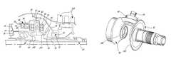
Theengine 10 includes a high pressure shaft orspool 22 interconnecting the rotors of the high pressure turbine andcompressor sections compressor sections combustor 16. The engine further includes a low pressure/power shaft orspool 24 to which the rotor(s) of the lowpressure turbine section 20 are connected, such that the rotor(s) of the lowpressure turbine section 20 drive the rotation of thelow pressure spool 24. Thelow pressure spool 24 is in driving engagement with the rotor(s) of the lowpressure compressor section 12 and with arotatable load 26, as will be further detailed below. Therotatable load 26 is driven by thelow pressure spool 24 with a fixed ratio between their rotational speeds.
The twospools high pressure spool 22 is hollow and thelow pressure spool 24 extends therethrough. Theengine 10 further includes avariable transmission 30 driven by thelow pressure spool 24 and driving arotatable transmission shaft 32. In a particular embodiment, thetransmission shaft 32 is hollow and thelow pressure spool 24 extends therethrough.
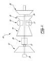
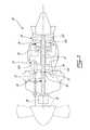
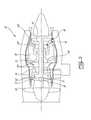
Theengine 10 schematically illustrated inFIG. 1 can be any type of gas turbine engine. In a particular embodiment shown inFIG. 2 , thegas turbine engine 10 is a turboshaft or turboprop engine, and in the particular embodiment ofFIG. 3 , thegas turbine engine 10 is a turbofan engine. Referring to the embodiments ofFIGS. 2-3 , in each case the highpressure compressor section 14 includes at least one highpressure compressor rotor 114 directly connected to thehigh pressure spool 22. The highpressure turbine section 18 includes at least oneturbine rotor 118 also directly connected to thehigh pressure spool 22. The high pressure compressor andturbine rotors high pressure spool 22, so that they rotate at a same rotational speed. Alternately, the high pressure compressor rotor(s)114 and/or the high pressure turbine rotor(s)118 may be engaged to thehigh pressure spool 22 such that they rotate at a different rotational speed having a fixed ratio with respect to the rotational speed of thehigh pressure spool 22, for example by engagement through a fixed ratio transmission (not shown).
Still referring to the embodiments ofFIGS. 2-3 , thelow pressure turbine 20 includes at least one lowpressure turbine rotor 120 directly connected to thelow pressure spool 24 so that they rotate at a same rotational speed. Therotatable load 26 may include for example an output shaft (in full lines inFIG. 2 ) which the embodiment shown is an extension of thelow pressure spool 24 extending through thetransmission 30 and thetransmission shaft 32, a propeller (in dotted lines inFIG. 2 ) which in the embodiment shown is driven by thelow pressure spool 24 through agearbox 28, or a fan (FIG. 3 ). Other configurations are also possible.
Still referring to the embodiments ofFIGS. 2-3 , the lowpressure compressor section 12 includes at least one lowpressure compressor rotor 112 connected to thetransmission shaft 32 to be drivingly engaged to thelow pressure spool 24 through thetransmission 30. Thetransmission 30 is variable transmission, i.e. a transmission having a variable transmission ratio. In a particular embodiment, the transmission is a continuously variable transmission. Thetransmission 30 thus allows for a variation of the rotational speed of the low pressure compressor rotor(s)112 connected thereto while keeping the rotational speed of theturbine sections pressure compressor section 12 may additionally include one or more rotors directly connected to thelow pressure spool 24 so that they rotate at a same rotational speed.
It is understood that the particular engine configurations ofFIGS. 2-3 are shown as an example only and that other engine configurations may be used. For example, the engine may be an auxiliary power unit (APU) or a land-based gas turbine engine. The low pressure spool and high pressure spools may extend separately to define an engine having a rear drive. The low pressure compressor rotor may be engaged to the low pressure spool with thetransmission 30 through a connecting shaft engaged to the low pressure spool and extending along a different axis than the low and high pressure spools or extending through the high pressure spool, etc.
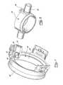
Referring toFIG. 4-7 , in a particular embodiment, thetransmission 30 is a continuously variable transmission generally including aninput drive member 40 engaged to thelow pressure spool 24, acompressor drive member 42 engaged to the rotor(s)112 of the lowpressure compressor section 12, at least onemovable member 44 engaged to thedrive members drive members actuation mechanism 46 connected to themovable member 44 and determining its position.
In the embodiment shown, theinput drive member 40 is a drive disc defining atoroidal engagement surface 140 and thecompressor drive member 42 is also a drive disc defining atoroidal engagement surface 142 facing theengagement surface 140 of theinput drive member 40, but spaced apart therefrom. Three circumferentially spaced apartmovable members 44 in the form of idler discs drivingly engage thetoroidal engagement surfaces idler disc 44 is supported by a respective disc support56 (shown in isolation inFIG. 8 ) which is in turn pivotally supported such as to allow a tilting movement of eachidler disc 44 with respect to the radial direction of theengine 10, for example by two coaxialopposing pins 60 radially extending from a body of the support along a same axis. One or more bearing(s)58 connect eachidler disc 44 to therespective support 56 to allow rotation of theidler disc 44.
Referring particularly toFIG. 4 , thetransmission shaft 32 andcompressor drive member 42 are supported by a trust bearing52 defining a rotatable connection between thetransmission shaft 32 and a fixed bearinghousing 54 which receives thetransmission 30 therein. Thetransmission shaft 32 is also rotationally supported around thelow pressure spool 24 by other bearing and associated support structure. In the embodiment shown, two lowpressure compressor rotors 112 are directly connected to thetransmission shaft 32. Thecompressor drive member 42 is directly connected to thetransmission shaft 32 in a fixed relative position with respect thereto, for example through a keyedconnection 50.
Still referring toFIG. 4 , theinput drive member 40 is supported by another trust bearing72 defining a rotatable connection between theinput drive member 40 and an axially extendingwall 80 of anaxial loading piston 74. Theaxial loading piston 74 is annular and includes aradial flange 76 defining a wall of anoil gallery 78, such that oil pressure in theoil gallery 78 presses thepiston 74 toward theinput drive member 40. Theinput drive member 40 is directly connected to thelow pressure spool 24 such that they rotate at a same rotational speed, but through aconnection 48 allowing for a relative movement along the axial direction. As such, movement of theaxial loading piston 74 toward theinput drive member 40 provides a bias ensuring that thetoroidal surfaces idler discs 44.
Alternately, thecompressor drive member 42 may be axially slidable with respect to thetransmission shaft 32 and theinput drive member 40 may be fixedly connected to thelow pressure spool 24.
In the embodiment shown and with particular reference toFIGS. 4 and 7 , theactuation mechanism 46 is provided as an annular piston. Thepiston 46 includes an annular axially extendingouter wall 68, and an annular L-shapedflange 66 extending inwardly from theouter wall 68, with a radial portion of theflange 66 being connected to theouter wall 68. Referring toFIG. 4 , theflange 66 is received in an annular cavity defining twooil galleries 70, one on each side of theflange 66. As such, a variation in the relative oil pressure in thegalleries 70 produces a translation of thepiston 46 along the axial direction of theengine 10. The oil pressure within the galleries is controlled by any appropriate type of control system, for example by the engine control unit, to vary the ratio of thetransmission 30 to obtain the desired rotational speed for the low pressure compressor rotor(s)112.
Still with particular reference toFIGS. 4 and 7 , thepiston 46 further includes three axially extendingarm 62, one engaging acomplementary portion 64 of eachdisc support 56. The engagement of thearm 62 andcomplementary portion 64 of thesupport 56 is offset from the axis of thepins 60, such that the translation of thepiston 46 pivots thesupport 56 about the axis of thepins 60. In the embodiment shown inFIG. 7 , thearm 62 andcomplementary portion 64 engage each other through a toothed engagement; other configurations are also possible.
Other configurations for thetransmission 30 are also possible, provided they allow for a variation in the ratio between the rotational speed(s) of the low pressure compressor rotor(s)112 and of thelow pressure spool 24, and preferably a continuous variation thereof.
In a particular embodiment, the rotational speeds of the gas turbine engine are tuned according to the following. A rotational speed is selected for the high pressure compressor rotor(s)114 and the high pressure turbine rotor(s)118, for example to obtain a desired fuel consumption for the engine or based on a power demand on the engine. The high pressure compressor rotor(s)114 are then rotated by the high pressure turbine rotor(s)118 at the selected rotational speed through thehigh pressure spool 22. In a particular embodiment, thehigh pressure rotors high pressure spool 22 rotate at a same rotational speed.
A rotational speed is selected for theload 26, and theload 26 is rotated at the selected rotational speed by the low pressure turbine rotor(s)120 through thelow pressure spool 24. In a particular embodiment, the low pressure turbine rotor(s)120 and thelow pressure spool 24 rotate at a same rotational speed.
A rotational speed is selected for the low pressure compressor rotor(s)112, for example based on desired performances (e.g. desired exhaust pressure) of thelow pressure compressor 12. The variable ratio of thetransmission 30 is then adjusted to rotate the low pressure compressor rotor(s)112 at the selected speed with the low pressure turbine rotor(s)120 through thelow pressure spool 24. In a particular embodiment, the rotational speed of the load remains constant or substantially constant over a period of time, while the rotational speed of the low pressure compressor rotor(s)112 is varied.
In the embodiment shown inFIGS. 4-7 , the transmission ratio is adjusted by changing the orientation of theidler discs 44 in driving engagement with the twodrive discs oil galleries 70 defined on opposed sides of thepiston flange 66.
Thetransmission 30 may thus allow the rotational speed of the low pressure compressor rotor(s)112 to be varied in a relatively wide range while keeping the rotational speed of thelow pressure spool 24 within a relatively small range, by varying the transmission ratio to obtain the desired rotational speed of the low pressure compressor rotor(s)112. The rotational speed of the low pressure compressor rotor(s)112 can thus be tuned independently of the other rotatable members.
Accordingly, in a particular embodiment, the variation of the low pressure compressor rotor(s)112 introduce a variability in the gas turbine thermodynamic cycle, which may allow to obtain a specific fuel consumption improvement by allowing the turbo machinery to operate closer to its optimum design point regardless of the power demand on theengine 10. For example, the rotational speed of the low pressure compressor rotor(s)112 may be varied while keeping the rotational speed of the low pressure turbine rotor(s)120 constant or substantially constant, for example in the case of a turboprop or turboshaft engine where the load typically runs at a discrete governed speed over a wide range of power, or in the case of generator engines where the load is typically constant. Thetransmission 30 may accordingly allow to optimize the performances and surge margin of thelow pressure compressor 12, allowing the low pressure compressor rotor(s)112 to rotate at an optimum speed independent of the required load speed.
In a particular embodiment, the load speed is controlled by the governor of the low pressure turbine rotor(s)120 to match the requirements of the load, the independentlyrotatable spools variable transmission 30 allows the low pressure compressor rotor(s)112 to be run at a speed independent of the load requirement; as such both the low pressure and highpressure compression sections
Accordingly, the transmission may also allow for the high pressure section to be maintained at a more constant speed throughout the range of power demands. In a particular embodiment, thetransmission 30 allows for the rotational speed of the highpressure turbine section 18 to be kept within a range of approximately from 80 to 100% of its optimal speed, by contrast with an equivalent engine having the low pressure compressor directly driven by the low pressure spool which typically has the high pressure turbine section rotating within a range of 50 to 100% of its optimal speed.
In a particular embodiment where the engine is a turbofan engines, thetransmission 30 may allow for the low pressure or boost compressor rotor(s)112 to rotate at a different speed than would result from a fixed ratio drive from thelow pressure spool 24, which may allow for the reduction of bleed and the elimination of variable geometry on the low pressure compressor of certain high bypass engines by allowing for better management of the part load operation.
In a particular embodiment, active control of the ratio of thetransmission 30 may also allow for the modification of the dynamic behaviour and/or thrust response of theengine 10.
In a particular embodiment where the engine is an APU, thevariable transmission 30 may allow for the delivery pressure of the lowpressure compressor section 12 to be matched to the aircraft requirement while allowing thepower turbine section 20 to run at the required generator speed and the core engine to find its own optimum speed based on engine cycle part load matching behaviour.
Accordingly, the above description is meant to be exemplary only, and one skilled in the art will recognize that changes may be made to the embodiments described without departing from the scope of the invention disclosed. Modifications which fall within the scope of the present invention will be apparent to those skilled in the art, in light of a review of this disclosure, and such modifications are intended to fall within the appended claims.
Claims (19)
1. A method of adjusting a rotational speed of at least one low pressure compressor rotor of a gas turbine engine having independently rotatable low pressure and high pressure spools, the method comprising:
rotating at least one rotor of a high pressure compressor of a core section of the engine with at least one rotor of a high pressure turbine of the core section through the high pressure spool;
rotating at least one rotor of a low pressure turbine with a flow of exhaust gases from the high pressure turbine section;
rotating the low pressure spool with the at least one rotor of the low pressure turbine;
rotating a load of the engine with the low pressure spool;
driving a rotation of the at least one low pressure compressor rotor with the low pressure spool through a continuously variable transmission defining a variable transmission ratio between rotational speeds of the at least one low pressure compressor rotor and of the low pressure spool, the continuously variable transmission including a first drive member coupled to the low pressure spool, a second drive member coupled to the at least one low pressure compressor rotor, at least one movable member drivingly engaged to the first and second drive members and having a relative position with respect to the first and second drive members, and an actuation mechanism connected to the at least one movable member; and
adjusting the transmission ratio to obtain a desired rotational speed for the low pressure compressor rotor by varying the relative position of the at least one movable member with the actuation mechanism, the relative position determining a variable rotational speed ratio between the rotational speeds of the first and second drive members.
2. The method according toclaim 1 , wherein the load is rotated at a constant or substantially constant rotational speed.
3. The method according toclaim 1 , wherein the method is repeated over a period of time and the desired rotational speed and transmission ratio are varied over the period of time.
4. The method according toclaim 1 , wherein adjusting the transmission ratio includes changing an orientation of the at least one moveable member.
5. The method according toclaim 4 , wherein changing the orientation of the at least one movable member includes varying a relative pressure between two oil galleries defined on opposed sides of a part of a piston engaged to the moveable member.
6. The method according toclaim 1 , wherein the at least one rotor of the high pressure compressor, the at least one rotor of a high pressure turbine and the high pressure spool are rotated at a same rotational speed, and the at least one rotor of the low pressure turbine is rotated at a same rotational speed as that of the low pressure spool.
7. A method of adjusting rotational speeds of a gas turbine engine having independently rotatable low pressure and high pressure spools, the method comprising:
selecting a first rotational speed for at least one high pressure compressor rotor and at least one high pressure turbine rotor of a core of the gas turbine engine;
rotating the at least one high pressure compressor rotor with the at least one high pressure turbine rotor through the high pressure spool at the first rotational speed, a ratio between the first rotational speed and a rotational speed of the high pressure spool having a fixed value;
selecting a second rotational speed for a load of the engine;
selecting a third rotational speed for at least one low pressure compressor rotor of the engine; and
adjusting a variable ratio of a continuously variable transmission including a first drive member coupled to the low pressure spool, a second drive member coupled to the at least one low pressure compressor rotor, at least one movable member drivingly engaged to the first and second drive members and having a relative position with respect to the first and second drive members, and an actuation mechanism connected to the at least one movable member, the variable ratio being adjusted to rotate the at least one low pressure compressor rotor at the third rotational speed while rotating the load at the second rotational speed with at least one low pressure turbine rotor of the engine through the low pressure spool, the variable ratio being adjusted by varying the relative position of the at least one movable member with the actuation mechanism, the relative position determining a variable rotational speed ratio between the rotational speeds of the first and second drive members, a ratio between the second rotational speed and a rotational speed of the low pressure spool having a fixed value.
8. The method according toclaim 7 , wherein the first rotational speed is selected to obtain a desired fuel consumption for the engine.
9. The method according toclaim 7 , wherein the first rotational speed is selected based on a power demand on the engine.
10. The method according toclaim 7 , wherein the method is repeated over a period of time and the second rotational speed remains constant while the third rotational speed is varied.
11. The method according toclaim 7 , wherein the third rotational speed is selected based on desired exhaust pressure of the low pressure compressor.
12. The method according toclaim 7 , wherein adjusting a variable ratio of the transmission includes changing an orientation of the at least one movable member.
13. The method according toclaim 12 , wherein changing the orientation of the at least one movable member includes varying a relative pressure between two oil galleries defined on opposed sides of a part of a piston connected to the moveable member.
14. The method according toclaim 7 , wherein the ratio between the first rotational speed and the rotational speed of the high pressure spool is 1, and the ratio between the second rotational speed and the rotational speed of the low pressure spool is 1.
15. A gas turbine engine comprising:
a core engine having at least one high pressure turbine rotor and at least one high pressure compressor rotor connected to a high pressure spool such as to be in driving engagement therewith, the high pressure spool being rotatable, a first fixed rotational speed ratio being defined between a rotational speed of the at least one high pressure turbine rotor and a rotational speed of the at least one high pressure compressor rotor;
a low pressure spool rotatable independently of the high pressure spool;
at least one low pressure turbine rotor connected to the low pressure spool such as to be in driving engagement therewith, a second fixed rotational speed ratio being defined between a rotational speed of the at least one low pressure turbine rotor and a rotational speed of the low pressure spool, the at least one low pressure turbine rotor in fluid communication with the at least one high pressure turbine rotor;
a rotatable load in driving engagement with the low pressure spool, a third fixed rotational speed ratio being defined between a rotational speed of the rotatable load and the rotational speed of the low pressure spool; and
a low pressure compressor rotor in fluid communication with the at least one high pressure compressor rotor, the low pressure compressor rotor being in driving engagement with the low pressure spool through a continuously variable transmission, the continuously variable transmission defining a variable rotational speed
ratio between the rotational speed of the low pressure spool and a rotational speed of the low pressure compressor rotor, the continuously variable transmission including a first drive member coupled to the low pressure spool, a second drive member coupled to the low pressure compressor, at least one movable member drivingly engaged to the first and second drive members, and an actuation mechanism connected to the at least
one movable member, the at least one movable member having a relative position with respect to the first and second drive members, the relative position being variable, the relative position determining a variable rotational speed ratio between the rotational speeds of the first and second drive members, and the actuation mechanism determining the relative position.
16. The engine as defined inclaim 15 , wherein the at least one high pressure turbine rotor and the at least one high pressure compressor rotor are directly connected to the high pressure spool such as to be rotatable therewith at a same rotational speed, and the at least one low pressure turbine rotor is directly connected to the low pressure spool such as to be rotatable therewith at a same rotational speed.
17. The engine as defined inclaim 15 , wherein the first and second drive members are defined as first and second drive discs with toroidal surfaces facing each other in a spaced apart manner, at least one of the first and second drive discs being axially moveable, the first and second drive discs being biased toward one another and in engagement with the at least one moveable member.
18. The engine as defined inclaim 17 , wherein the at least one movable member includes a plurality of idler discs each in driving engagement with the toroidal surface of each of the first and second drive discs, the actuation mechanism controlling an angle of the plurality of idler discs with respect to the toroidal surface of each of the first and second drive discs.
19. The engine as defined inclaim 15 , wherein the rotatable load is selected from the group consisting of a fan, a propeller and an output shaft.
Priority Applications (2)
| Application Number | Priority Date | Filing Date | Title |
|---|---|---|---|
| US13/804,799US9752500B2 (en) | 2013-03-14 | 2013-03-14 | Gas turbine engine with transmission and method of adjusting rotational speed |
| CA2844186ACA2844186C (en) | 2013-03-14 | 2014-02-27 | Gas turbine engine with transmission and method of adjusting rotational speed |
Applications Claiming Priority (1)
| Application Number | Priority Date | Filing Date | Title |
|---|---|---|---|
| US13/804,799US9752500B2 (en) | 2013-03-14 | 2013-03-14 | Gas turbine engine with transmission and method of adjusting rotational speed |
Publications (2)
| Publication Number | Publication Date |
|---|---|
| US20140260295A1 US20140260295A1 (en) | 2014-09-18 |
| US9752500B2true US9752500B2 (en) | 2017-09-05 |
Family
ID=51521068
Family Applications (1)
| Application Number | Title | Priority Date | Filing Date |
|---|---|---|---|
| US13/804,799Active2034-11-05US9752500B2 (en) | 2013-03-14 | 2013-03-14 | Gas turbine engine with transmission and method of adjusting rotational speed |
Country Status (2)
| Country | Link |
|---|---|
| US (1) | US9752500B2 (en) |
| CA (1) | CA2844186C (en) |
Cited By (21)
| Publication number | Priority date | Publication date | Assignee | Title |
|---|---|---|---|---|
| US20160138603A1 (en)* | 2014-11-18 | 2016-05-19 | Rolls-Royce North American Technologies, Inc. | Split axial-centrifugal compressor |
| US9982676B2 (en) | 2014-11-18 | 2018-05-29 | Rolls-Royce North American Technologies Inc. | Split axial-centrifugal compressor |
| US20180223739A1 (en)* | 2017-02-09 | 2018-08-09 | Pratt & Whitney Canada Corp. | Turbine rotor with low over-speed requirements |
| US20180283499A1 (en)* | 2017-03-28 | 2018-10-04 | Sikorsky Aircraft Corporation | Rotorcraft internal transfer member transmission |
| US10393027B2 (en) | 2016-07-19 | 2019-08-27 | Pratt & Whitney Canada Corp. | Gas turbine engine shaft architecture and associated method of disassembly |
| US10465611B2 (en) | 2016-09-15 | 2019-11-05 | Pratt & Whitney Canada Corp. | Reverse flow multi-spool gas turbine engine with aft-end accessory gearbox drivingly connected to both high pressure spool and low pressure spool |
| US10519871B2 (en) | 2017-05-18 | 2019-12-31 | Pratt & Whitney Canada Corp. | Support assembly for a propeller shaft |
| US10738709B2 (en) | 2017-02-09 | 2020-08-11 | Pratt & Whitney Canada Corp. | Multi-spool gas turbine engine |
| US10746188B2 (en) | 2017-03-14 | 2020-08-18 | Pratt & Whitney Canada Corp. | Inter-shaft bearing connected to a compressor boost system |
| US10815899B2 (en) | 2016-11-15 | 2020-10-27 | Pratt & Whitney Canada Corp. | Gas turbine engine accessories arrangement |
| US11015522B2 (en)* | 2016-11-15 | 2021-05-25 | Pratt & Whitney Canada Corp. | Gearbox for gas turbine engine |
| US11035293B2 (en) | 2016-09-15 | 2021-06-15 | Pratt & Whitney Canada Corp. | Reverse flow gas turbine engine with offset RGB |
| US11174782B2 (en) | 2017-02-10 | 2021-11-16 | Pratt & Whitney Canada Corp. | Planetary gearbox for gas turbine engine |
| US11174916B2 (en) | 2019-03-21 | 2021-11-16 | Pratt & Whitney Canada Corp. | Aircraft engine reduction gearbox |
| US11267563B2 (en)* | 2018-10-29 | 2022-03-08 | Pratt & Whitney Canada Corp. | Aircraft engine with clutch and mechanical lock |
| US11268453B1 (en) | 2021-03-17 | 2022-03-08 | Pratt & Whitney Canada Corp. | Lubrication system for aircraft engine reduction gearbox |
| US11408352B2 (en) | 2016-09-15 | 2022-08-09 | Pratt & Whitney Canada Corp. | Reverse-flow gas turbine engine |
| US20220252008A1 (en)* | 2021-02-08 | 2022-08-11 | General Electric Company | Propulsion system configurations and methods of operation |
| US11536153B2 (en) | 2018-08-08 | 2022-12-27 | Pratt & Whitney Canada Corp. | Turboshaft gas turbine engine |
| US20250214723A1 (en)* | 2022-03-29 | 2025-07-03 | Ishikawa Energy Research Co., Ltd. | Flight device and flight device control method |
| US12441495B2 (en)* | 2022-03-29 | 2025-10-14 | Ishikawa Energy Research Co., Ltd. | Flight device and flight device control method |
Families Citing this family (16)
| Publication number | Priority date | Publication date | Assignee | Title |
|---|---|---|---|---|
| US10358982B2 (en)* | 2013-07-07 | 2019-07-23 | United Technologies Corporation | Fan drive gear system mechanical controller |
| FR3017159B1 (en)* | 2014-01-31 | 2016-03-04 | Snecma | AIR SUPPLYING AN AIR CONDITIONING CIRCUIT OF A CABIN OF AN AIRCRAFT FROM ITS TURBOPROPULSOR |
| US20160160761A1 (en)* | 2014-12-09 | 2016-06-09 | United Technologies Corporation | Gas Turbine Engine With Single Turbine Driving Two Compressors |
| US10240521B2 (en)* | 2015-08-07 | 2019-03-26 | Pratt & Whitney Canada Corp. | Auxiliary power unit with variable speed ratio |
| CN105569743A (en)* | 2016-03-03 | 2016-05-11 | 哈尔滨工程大学 | Variable Brayton cycle gas turbine |
| US10215052B2 (en) | 2017-03-14 | 2019-02-26 | Pratt & Whitney Canada Corp. | Inter-shaft bearing arrangement |
| CN108104954B (en)* | 2017-12-01 | 2018-12-11 | 中国直升机设计研究所 | A kind of turboshaft engine power rating monitoring method |
| US11078841B2 (en)* | 2018-04-09 | 2021-08-03 | The Boeing Company | Bleed air systems for use with aircraft and related methods |
| CA3055056A1 (en)* | 2018-09-11 | 2020-03-11 | Pratt & Whitney Canada Corp. | Gas turbine engine and method of creating classes of same |
| US11041444B2 (en)* | 2018-11-02 | 2021-06-22 | Pratt & Whitney Canada Corp. | Gas turbine engine with differential gearbox |
| US11623756B2 (en)* | 2019-12-20 | 2023-04-11 | Pratt & Whitney Canada Corp. | Gas turbine engine with variable speed output |
| US11898490B2 (en) | 2022-05-05 | 2024-02-13 | Rtx Corporation | Transmission and method for control of boost spool |
| US11976598B2 (en) | 2022-05-05 | 2024-05-07 | Rtx Corporation | Transmission and method for control of boost spool |
| US11692493B1 (en) | 2022-05-05 | 2023-07-04 | Raytheon Technologies Corporation | Fluidic valve configuration for boost spool engine |
| US11639690B1 (en)* | 2022-05-05 | 2023-05-02 | Raytheon Technologies Corporation | Boost spool flow control and generator load matching via load compressor |
| US11692491B1 (en) | 2022-05-05 | 2023-07-04 | Raytheon Technologies Corporation | Transmission and method for control of boost spool |
Citations (169)
| Publication number | Priority date | Publication date | Assignee | Title |
|---|---|---|---|---|
| US1833475A (en)* | 1930-10-29 | 1931-11-24 | Hartford Special Machinery Co | Variable speed transmission |
| US3150544A (en) | 1963-04-25 | 1964-09-29 | Avco Corp | Multi-speed gear reduction transmission |
| US3368347A (en) | 1964-05-22 | 1968-02-13 | Wickman Axel Charles | Power transmission system for a gas turbine engine |
| US3394617A (en)* | 1966-03-21 | 1968-07-30 | Gen Motors Corp | Transmission and control system |
| US3433095A (en) | 1966-10-21 | 1969-03-18 | Gen Motors Corp | Split power transmission |
| US3574289A (en)* | 1969-05-06 | 1971-04-13 | Gen Motors Corp | Transmission and control system |
| US3581587A (en)* | 1969-05-06 | 1971-06-01 | Gen Motors Corp | Transmission |
| US3585795A (en) | 1967-12-30 | 1971-06-22 | Daimler Benz Ag | Gas turbine assembly having low-pressure groups and high-pressure groups adapted to be selectively connected either in series or in parallel |
| US3611834A (en)* | 1969-10-13 | 1971-10-12 | Gen Motors Corp | Fan drive |
| US3641766A (en) | 1969-11-26 | 1972-02-15 | Gen Electric | Gas turbine engine constant speed thrust modulation |
| US3710576A (en) | 1971-02-22 | 1973-01-16 | D Evans | Dual clutch free turbine engine |
| US3739658A (en)* | 1971-06-07 | 1973-06-19 | Gen Motors Corp | Transmission |
| US3965684A (en) | 1974-01-23 | 1976-06-29 | Hitachi, Ltd. | Device for controlling speed of turbine |
| US4008628A (en) | 1974-06-06 | 1977-02-22 | Orshansky Transmission Corporation | Hydromechanical transmission |
| US4018045A (en) | 1971-06-25 | 1977-04-19 | Motoren- Und Turbinen-Union Munchen Gmbh | Regulating device for a prime mover, more particularly for a single-spool gas turbine |
| US4064690A (en)* | 1974-05-17 | 1977-12-27 | United Turbine Ab & Co. | Gas turbine power plant |
| US4118927A (en)* | 1975-12-05 | 1978-10-10 | United Turbine Ab & Co. Kommanditbolag | Gas turbine power plant |
| US4122732A (en)* | 1977-01-17 | 1978-10-31 | General Motors Corporation | Hydromechanical mechanical continuously variable transmission |
| US4186554A (en) | 1975-11-10 | 1980-02-05 | Possell Clarence R | Power producing constant speed turbine |
| US4195473A (en) | 1977-09-26 | 1980-04-01 | General Motors Corporation | Gas turbine engine with stepped inlet compressor |
| US4222235A (en)* | 1977-07-25 | 1980-09-16 | General Electric Company | Variable cycle engine |
| US4251987A (en)* | 1979-08-22 | 1981-02-24 | General Electric Company | Differential geared engine |
| US4326375A (en)* | 1976-09-24 | 1982-04-27 | Kronogard Sven Olof | Gas turbine-transmission plant |
| US4354401A (en)* | 1980-04-25 | 1982-10-19 | Aisin Seiki Co., Ltd. | Automatic transmission for automobiles |
| US4355547A (en)* | 1979-05-30 | 1982-10-26 | Bl Cars Limited | Continuously variable ratio transmission |
| US4412460A (en) | 1980-06-23 | 1983-11-01 | S.A. Automobiles Citroen | Two-speed couplings |
| US4458561A (en)* | 1982-05-21 | 1984-07-10 | Frank Andrew A | Control system and method for a power delivery system having a continuously variable ratio transmission |
| US4632337A (en) | 1981-09-21 | 1986-12-30 | Hughes Helicopters, Inc. | Helicopter rotor transmission systems |
| US4751816A (en)* | 1986-10-08 | 1988-06-21 | Rolls-Royce Plc | Turbofan gas turbine engine |
| US4782658A (en)* | 1987-05-07 | 1988-11-08 | Rolls-Royce Plc | Deicing of a geared gas turbine engine |
| US4827712A (en)* | 1986-12-23 | 1989-05-09 | Rolls-Royce Plc | Turbofan gas turbine engine |
| US4858493A (en)* | 1987-05-04 | 1989-08-22 | Sundstrand Corporation | Multi-range, dissipative, infinitely variable ratio transmission |
| US4858428A (en) | 1986-04-24 | 1989-08-22 | Paul Marius A | Advanced integrated propulsion system with total optimized cycle for gas turbines |
| US4916894A (en)* | 1989-01-03 | 1990-04-17 | General Electric Company | High bypass turbofan engine having a partially geared fan drive turbine |
| US4936748A (en)* | 1988-11-28 | 1990-06-26 | General Electric Company | Auxiliary power source in an unducted fan gas turbine engine |
| US4969325A (en)* | 1989-01-03 | 1990-11-13 | General Electric Company | Turbofan engine having a counterrotating partially geared fan drive turbine |
| US5010729A (en)* | 1989-01-03 | 1991-04-30 | General Electric Company | Geared counterrotating turbine/fan propulsion system |
| US5011465A (en) | 1990-04-20 | 1991-04-30 | Deere & Company | Wide speed-range multi-speed power shift transmission |
| US5011464A (en) | 1990-03-23 | 1991-04-30 | Sundstrand Corporation | Two-speed automatic transmission |
| US5033996A (en) | 1988-09-12 | 1991-07-23 | Heinz Frey | Continuously variable drive |
| US5103631A (en)* | 1989-03-14 | 1992-04-14 | Rolls-Royce Plc | Differential gear assembly |
| US5125806A (en)* | 1990-06-18 | 1992-06-30 | Sundstrand Corporation | Integrated variable speed compressor drive system |
| US5328419A (en) | 1992-04-10 | 1994-07-12 | Borg-Warner Automotive, Inc. | Two-speed alternator drive |
| US5345760A (en) | 1993-02-05 | 1994-09-13 | General Electric Company | Turboprop booster |
| US5577973A (en) | 1995-07-20 | 1996-11-26 | General Motors Corporation | Two-mode, split power, electro-mechanical transmission |
| US5694567A (en) | 1995-02-09 | 1997-12-02 | Integrated Device Technology, Inc. | Direct-mapped cache with cache locking allowing expanded contiguous memory storage by swapping one or more tag bits with one or more index bits |
| US5694768A (en)* | 1990-02-23 | 1997-12-09 | General Electric Company | Variable cycle turbofan-ramjet engine |
| US5782433A (en)* | 1995-04-27 | 1998-07-21 | Advanced Technology Institute Of Commuter-Helicopter, Ltd. | Engine deceleration device and power transmission device for helicopters |
| US5842945A (en)* | 1995-02-27 | 1998-12-01 | Isuzu Motors Limited | Toroidal continuous variable transmission with a limited slip differential between the output toroid disks |
| US5873800A (en) | 1993-06-11 | 1999-02-23 | Synkinetics, Inc. | Variable output speed drive |
| US6042499A (en)* | 1995-01-27 | 2000-03-28 | Advanced Technology Institute Of Commuter-Helicopter, Ltd. | Power transmission device for helicopter |
| US6053452A (en) | 1997-03-26 | 2000-04-25 | Advanced Technology Institute Of Commuter-Helicopter, Ltd. | Compensation apparatus for main rotor torque |
| US6082967A (en)* | 1997-03-27 | 2000-07-04 | Societe Nationale D'etude Et De Construction De Moteurs D'aviation "Snecma" | Constant-speed twin spool turboprop unit |
| US6158210A (en)* | 1998-12-03 | 2000-12-12 | General Electric Company | Gear driven booster |
| US6254504B1 (en) | 1999-03-24 | 2001-07-03 | Advanced Technology Institute Of Commuter-Helicopter, Ltd. | Power transmission apparatus for helicopter |
| US6302356B1 (en)* | 1998-08-21 | 2001-10-16 | Rolls-Royce Corporation | Helicopter two stage main reduction gearbox |
| US6364249B1 (en)* | 1999-09-30 | 2002-04-02 | Pratt & Whitney Canada Corp. | Engine integrated with rotary wing aircraft transmission |
| US6494806B2 (en)* | 1999-12-24 | 2002-12-17 | Honda Giken Kogyo Kabushiki Kaisha | Lubricating oil supply system for infinitely variable transmission |
| US20020189231A1 (en)* | 2001-06-19 | 2002-12-19 | Snecma Moteurs | Emergency device for relighting a windmilling turbojet |
| US6497634B1 (en)* | 1998-08-06 | 2002-12-24 | Veritran, Inc. | Infinitely variable epicyclic transmissions |
| US6524068B2 (en) | 2000-05-24 | 2003-02-25 | Cartercopters, L.L.C. | Variable pitch aircraft propeller control with two-speed transmission |
| US20030115885A1 (en)* | 2001-12-21 | 2003-06-26 | Macfarlane Ian Alexander | Offset drive for gas turbine engine |
| US6607357B2 (en) | 2001-02-02 | 2003-08-19 | Agusta S.P.A. | Aircraft constant-velocity transmission rotor |
| US20030232692A1 (en) | 2002-06-18 | 2003-12-18 | Yung-Tung Chen | Transmission and variable speed system |
| US6695254B2 (en) | 2002-03-20 | 2004-02-24 | Eurocopter | Rotary-wing aircraft rotor with constant velocity drive |
| US20040043856A1 (en) | 2001-10-22 | 2004-03-04 | Ai Xiaolan | Electro-mechnical infinitely variable transmission |
| US6739120B2 (en)* | 2002-04-29 | 2004-05-25 | General Electric Company | Counterrotatable booster compressor assembly for a gas turbine engine |
| US6763654B2 (en)* | 2002-09-30 | 2004-07-20 | General Electric Co. | Aircraft gas turbine engine having variable torque split counter rotating low pressure turbines and booster aft of counter rotating fans |
| US20040255590A1 (en)* | 2003-06-23 | 2004-12-23 | Pratt & Whiney Canada Corp. | Differential geared turbine engine with torque modulation capability |
| US20040266580A1 (en) | 2003-06-24 | 2004-12-30 | Stevenson Paul D. | Seven-speed transmission |
| US20050132693A1 (en)* | 2003-12-22 | 2005-06-23 | Pratt & Whitney Canada Corp. | Gas turbine engine architecture |
| US20060010875A1 (en) | 2004-07-16 | 2006-01-19 | Mahoney Timothy D | Gas turbine engine bleed air power assist system and method |
| US7044877B2 (en) | 2003-04-21 | 2006-05-16 | The Timken Company | Two speed transmission with smooth power shift |
| US20060205553A1 (en)* | 2002-02-11 | 2006-09-14 | Lee Paul Z | Continuously variable ratio transmission |
| US7107972B1 (en) | 2004-08-03 | 2006-09-19 | Accessible Technologies, Inc. | Multi-phase centrifugal supercharging air induction system |
| US20060236675A1 (en)* | 2005-04-20 | 2006-10-26 | Mtu Aero Engines Gmbh | Jet engine with compact arrangement of fan |
| US20070087892A1 (en)* | 2005-10-19 | 2007-04-19 | General Electric Company | Gas turbine engine assembly and methods of assembling same |
| US20070084186A1 (en)* | 2005-10-19 | 2007-04-19 | General Electric Company | Gas turbine engine assembly and methods of assembling same |
| US20070084190A1 (en)* | 2005-10-19 | 2007-04-19 | General Electric Company | Gas turbine engine assembly and methods of assembling same |
| US20070214786A1 (en)* | 2006-03-20 | 2007-09-20 | Stephan Arndt | Internal combustion engine and method of operating the engine |
| US20070265761A1 (en)* | 2006-05-11 | 2007-11-15 | Dooley Kevin A | Electric power generation system and method |
| US7296767B2 (en) | 2005-05-31 | 2007-11-20 | Sikorsky Aircraft Corporation | Variable speed transmission for a rotary wing aircraft |
| US20080060341A1 (en)* | 2004-01-08 | 2008-03-13 | Snecma Moteurs | Turbine engine with semi-fixed turbine driving a receiver controlled so as to preserve a roughly constant rotation speed |
| US20080098712A1 (en) | 2006-10-25 | 2008-05-01 | Sheridan William G | Rotor brake and windmilling lubrication system for geared turbofan engine |
| US20080120839A1 (en)* | 2006-11-29 | 2008-05-29 | Jan Christopher Schilling | Turbofan engine assembly and method of assembling same |
| US20080138195A1 (en)* | 2006-12-06 | 2008-06-12 | Ge Aircraft Engines | Variable coupling of turbofan engine spools via open differential gear set or simple planetary gear set for improved power extraction and engine operabiliby, with torque coupling for added flexability |
| US20080148881A1 (en)* | 2006-12-21 | 2008-06-26 | Thomas Ory Moniz | Power take-off system and gas turbine engine assembly including same |
| US7396209B2 (en) | 2003-02-28 | 2008-07-08 | Fallbrook Technologies Inc. | Continuously variable transmission |
| US7422543B2 (en) | 2005-09-14 | 2008-09-09 | Conocophillips Company | Rotation coupling employing torque converter and synchronization motor |
| US20080223640A1 (en) | 2003-07-14 | 2008-09-18 | Clauson Luke W | Methods and Devices for Altering the Transmission Ratio of a Drive System |
| US7481062B2 (en) | 2005-12-30 | 2009-01-27 | Honeywell International Inc. | More electric aircraft starter-generator multi-speed transmission system |
| US20090028739A1 (en)* | 2006-01-27 | 2009-01-29 | Vladislav Vladimirovich Velitsko | Ring turbo-piston engine and ring turbo-piston supercharger |
| US7490461B2 (en)* | 2005-10-19 | 2009-02-17 | General Electric Company | Gas turbine engine assembly and methods of assembling same |
| US7513120B2 (en) | 2005-04-08 | 2009-04-07 | United Technologies Corporation | Electrically coupled supercharger for a gas turbine engine |
| US7526913B2 (en)* | 2005-10-19 | 2009-05-05 | General Electric Company | Gas turbine engine assembly and methods of assembling same |
| US20090139243A1 (en)* | 2007-11-30 | 2009-06-04 | Michael Winter | Gas turbine engine with pylon mounted accessory drive |
| US7552582B2 (en)* | 2005-06-07 | 2009-06-30 | Honeywell International Inc. | More electric aircraft power transfer systems and methods |
| US7563192B2 (en)* | 2003-06-27 | 2009-07-21 | Nsk Ltd. | Toroidal-type continuously variable transmission |
| US7603844B2 (en)* | 2005-10-19 | 2009-10-20 | General Electric Company | Gas turbine engine assembly and methods of assembling same |
| US20090272121A1 (en)* | 2008-05-05 | 2009-11-05 | Nashed Youssef | Gas turbine aircraft engine with power variability |
| US20090293445A1 (en) | 2006-08-22 | 2009-12-03 | Ress Jr Robert A | Gas turbine engine with intermediate speed booster |
| US20090320491A1 (en)* | 2008-05-13 | 2009-12-31 | Copeland Andrew D | Dual clutch arrangement |
| US7651050B2 (en) | 2005-12-02 | 2010-01-26 | Sikorsky Aircraft Corporation | Variable speed gearbox with an independently variable speed tail rotor system for a rotary wing aircraft |
| US7685808B2 (en)* | 2005-10-19 | 2010-03-30 | General Electric Company | Gas turbine engine assembly and methods of assembling same |
| US7690185B2 (en) | 2005-12-09 | 2010-04-06 | Hispano-Suiza | System for driving accessory machines of a double-bodied turbine engine |
| US20100093476A1 (en) | 2007-02-16 | 2010-04-15 | Fallbrook Technologies Inc. | Infinitely variable transmissions, continuously variable transmissions, methods, assemblies, subassemblies, and components therefor |
| US7698884B2 (en)* | 2003-09-19 | 2010-04-20 | Rolls-Royce Plc | Power transmission arrangement |
| US7707909B2 (en) | 2005-10-21 | 2010-05-04 | Hispano-Suiza | Device for driving accessory machines of a gas turbine engine |
| US7727106B2 (en)* | 2004-10-01 | 2010-06-01 | Pierre Maheu | Continuously variable transmission |
| US7727110B2 (en) | 2003-08-11 | 2010-06-01 | Fallbrook Technologies Inc. | Continuously variable planetary gear set |
| US7740556B2 (en)* | 2003-07-18 | 2010-06-22 | Toyota Jidosha Kabushiki Kaisha | Hydraulic control apparatus and hydraulic control method |
| US7758302B2 (en) | 2005-10-21 | 2010-07-20 | Hispano-Suiza | Device for the offtake of mechanical power between the HP and LP shafts of a double-shaft turbine engine |
| US20100199666A1 (en)* | 2008-08-05 | 2010-08-12 | Vandyne Ed | Super-turbocharger having a high speed traction drive and a continuously variable transmission |
| US20100219779A1 (en) | 2009-03-02 | 2010-09-02 | Rolls-Royce Plc | Variable drive gas turbine engine |
| US20100223904A1 (en)* | 2009-03-09 | 2010-09-09 | Rolls-Royce Plc | Gas turbine engine |
| US20110036089A1 (en)* | 2009-08-06 | 2011-02-17 | Schaeffler Technologies Gmbh & Co. Kg | Turbocharger for an internal combustion engine |
| US7942635B1 (en)* | 2007-08-02 | 2011-05-17 | Florida Turbine Technologies, Inc. | Twin spool rotor assembly for a small gas turbine engine |
| US7942079B2 (en)* | 2007-02-16 | 2011-05-17 | Hamilton Sundstrand Corporation | Multi-speed gearbox for low spool driven auxiliary component |
| US20110185698A1 (en)* | 2010-01-29 | 2011-08-04 | Keith Morgan | Free gas turbine with constant temperature-corrected gas generator speed |
| US8015798B2 (en)* | 2007-12-13 | 2011-09-13 | United Technologies Corporation | Geared counter-rotating gas turbofan engine |
| US8063528B2 (en)* | 2009-12-18 | 2011-11-22 | General Electric Company | Counter-rotatable generator |
| US20110314788A1 (en)* | 2009-01-07 | 2011-12-29 | Airbus Operations (S.A.S.) | Aircraft Turbine Engine And Use Of Such A Turbine Engine |
| US8104262B2 (en)* | 2006-10-12 | 2012-01-31 | United Technologies Corporation | Dual function cascade integrated variable area fan nozzle and thrust reverser |
| US20120051883A1 (en)* | 2010-08-27 | 2012-03-01 | D Ercole Michele | Geared axial multistage expander device, system and method |
| US20120117940A1 (en)* | 2007-11-30 | 2012-05-17 | Michael Winter | Gas turbine engine with pylon mounted accessory drive |
| US8191352B2 (en)* | 2008-12-19 | 2012-06-05 | General Electric Company | Geared differential speed counter-rotatable low pressure turbine |
| US8292570B2 (en)* | 2008-01-25 | 2012-10-23 | United Technologies Corporation | Low pressure turbine with counter-rotating drives for single spool |
| US20120275898A1 (en)* | 2011-04-27 | 2012-11-01 | United Technologies Corporation | Blade Clearance Control Using High-CTE and Low-CTE Ring Members |
| EP2535544A2 (en) | 2011-06-14 | 2012-12-19 | Honeywell International, Inc. | Transverse mounted accessory gearbox |
| US20130000317A1 (en)* | 2011-06-28 | 2013-01-03 | United Technologies Corporation | Mechanism for turbine engine start from low spool |
| US8365514B1 (en)* | 2012-02-27 | 2013-02-05 | United Technologies Corporation | Hybrid turbofan engine |
| US8375695B2 (en)* | 2009-06-30 | 2013-02-19 | General Electric Company | Aircraft gas turbine engine counter-rotatable generator |
| US20130095974A1 (en)* | 2010-04-13 | 2013-04-18 | Kawasaki Jukogyo Kabushiki Kaisha | Planetary gear system and gear reducer |
| US20130098058A1 (en)* | 2011-10-19 | 2013-04-25 | United Technologies Corporation | Split accessory drive system |
| US20130104524A1 (en)* | 2011-11-02 | 2013-05-02 | United Technologies Corporation | Turbofan with gear-driven compressor and fan-driven core |
| US8439631B2 (en)* | 2008-09-05 | 2013-05-14 | Rolls-Royce Corporation | Shaft coupling arrangement |
| US20130195621A1 (en)* | 2012-01-31 | 2013-08-01 | Frederick M. Schwarz | Gas turbine engine with high speed low pressure turbine section and bearing support features |
| US20130192266A1 (en)* | 2012-01-31 | 2013-08-01 | United Technologies Corporation | Geared turbofan gas turbine engine architecture |
| US8500583B2 (en)* | 2009-11-04 | 2013-08-06 | Kawasaki Jukogyo Kabushiki Kaisha | Aircraft starter generator |
| US20130199156A1 (en)* | 2010-03-26 | 2013-08-08 | Robert A. Ress, Jr. | Adaptive fan system for a variable cycle turbofan engine |
| US8517672B2 (en)* | 2010-02-23 | 2013-08-27 | General Electric Company | Epicyclic gearbox |
| US20130223986A1 (en)* | 2012-02-29 | 2013-08-29 | Daniel Bernard Kupratis | Gas turbine engine with fan-tied inducer section and multiple low pressure turbine sections |
| US20130219856A1 (en)* | 2012-02-29 | 2013-08-29 | Gabriel L. Suciu | Counter-rotating low pressure turbine with gear system mounted to mid turbine frame |
| US20130259651A1 (en)* | 2012-04-02 | 2013-10-03 | Daniel Bernard Kupratis | Differential geared architecture for gas turbine engine |
| US8561383B2 (en) | 2004-12-01 | 2013-10-22 | United Technologies Corporation | Turbine engine with differential gear driven fan and compressor |
| US8590286B2 (en)* | 2007-12-05 | 2013-11-26 | United Technologies Corp. | Gas turbine engine systems involving tip fans |
| US20130324343A1 (en)* | 2012-05-30 | 2013-12-05 | Snecma | Reduction gear with epicyclic gear train having roller-bearing-mounted planet spindles |
| US20130327060A1 (en)* | 2012-06-07 | 2013-12-12 | Joseph T. Christians | Single turbine driving dual compressors |
| US20140157756A1 (en)* | 2007-09-21 | 2014-06-12 | United Technologies Corporation | Gas turbine engine compressor arrangement |
| US20140208760A1 (en)* | 2013-01-30 | 2014-07-31 | Pratt & Whitney Canada Corp. | Gas turbine engine with transmission |
| US20140223901A1 (en)* | 2013-02-08 | 2014-08-14 | Dana Limited | Internal combustion engine coupled turbocharger with an infinitely variable transmission |
| US20140250860A1 (en)* | 2013-03-07 | 2014-09-11 | Rolls-Royce Corporation | Multi-shaft gas turbine engine |
| US20140271135A1 (en)* | 2013-03-15 | 2014-09-18 | United Technologies Corporation | Turbofan Engine Bearing and Gearbox Arrangement |
| US20140290265A1 (en)* | 2013-01-30 | 2014-10-02 | Pratt & Whitney Canada Corp. | Gas turbine engine with transmission |
| US8869504B1 (en)* | 2013-11-22 | 2014-10-28 | United Technologies Corporation | Geared turbofan engine gearbox arrangement |
| US20150027101A1 (en)* | 2013-01-21 | 2015-01-29 | United Technologies Corporation | Geared gas turbine engine architecture for enhanced efficiency |
| US8956108B2 (en)* | 2012-05-11 | 2015-02-17 | Pratt & Whitney Canada Corp | Geared fan assembly |
| US20150176486A1 (en)* | 2013-12-19 | 2015-06-25 | Pratt & Whitney Canada Corp. | Gas turbine engine with transmission |
| US20150300248A1 (en)* | 2014-04-17 | 2015-10-22 | Airbus Operations Gmbh | Compressor arrangement and turboshaft engine with a compressor arrangement |
| US20160040601A1 (en)* | 2011-06-14 | 2016-02-11 | Honeywell International Inc. | Transverse mounted accessory gearbox |
| US20160047305A1 (en)* | 2014-08-15 | 2016-02-18 | General Electric Company | Multi-stage axial compressor arrangement |
| US20160061057A1 (en)* | 2012-12-20 | 2016-03-03 | United Technologies Corporation | Low pressure ratio fan engine having a dimensional relationship between inlet and fan size |
| US20160069297A1 (en)* | 2013-04-24 | 2016-03-10 | United Technoligies Corporation | Geared turbine engine with o-duct and thrust reverser |
| US20160167790A1 (en)* | 2014-11-20 | 2016-06-16 | Hamilton Sundstrand Corporation | Engine driven-shaft driven compressor utilizing infinitely variable transmission |
| US20160167789A1 (en)* | 2014-12-11 | 2016-06-16 | Rolls-Royce Plc | Cabin blower system |
| US20160195096A1 (en)* | 2013-08-29 | 2016-07-07 | United Technologies Corporation | Three spool geared turbofan with low pressure compressor drive gear system and mechanical controller |
| US20160222888A1 (en)* | 2015-02-03 | 2016-08-04 | United Technologies Corporation | Fan drive gear system |
| US20160230674A1 (en)* | 2015-02-09 | 2016-08-11 | United Technologies Corporation | Gear reduction for lower thrust geared turbofan |
| EP3135882A1 (en) | 2015-08-26 | 2017-03-01 | Honeywell International Inc. | Transverse mounted accessory gearbox |
- 2013
- 2013-03-14USUS13/804,799patent/US9752500B2/enactiveActive
- 2014
- 2014-02-27CACA2844186Apatent/CA2844186C/enactiveActive
Patent Citations (178)
| Publication number | Priority date | Publication date | Assignee | Title |
|---|---|---|---|---|
| US1833475A (en)* | 1930-10-29 | 1931-11-24 | Hartford Special Machinery Co | Variable speed transmission |
| US3150544A (en) | 1963-04-25 | 1964-09-29 | Avco Corp | Multi-speed gear reduction transmission |
| US3368347A (en) | 1964-05-22 | 1968-02-13 | Wickman Axel Charles | Power transmission system for a gas turbine engine |
| US3394617A (en)* | 1966-03-21 | 1968-07-30 | Gen Motors Corp | Transmission and control system |
| US3433095A (en) | 1966-10-21 | 1969-03-18 | Gen Motors Corp | Split power transmission |
| US3585795A (en) | 1967-12-30 | 1971-06-22 | Daimler Benz Ag | Gas turbine assembly having low-pressure groups and high-pressure groups adapted to be selectively connected either in series or in parallel |
| US3574289A (en)* | 1969-05-06 | 1971-04-13 | Gen Motors Corp | Transmission and control system |
| US3581587A (en)* | 1969-05-06 | 1971-06-01 | Gen Motors Corp | Transmission |
| US3611834A (en)* | 1969-10-13 | 1971-10-12 | Gen Motors Corp | Fan drive |
| US3641766A (en) | 1969-11-26 | 1972-02-15 | Gen Electric | Gas turbine engine constant speed thrust modulation |
| US3710576A (en) | 1971-02-22 | 1973-01-16 | D Evans | Dual clutch free turbine engine |
| US3739658A (en)* | 1971-06-07 | 1973-06-19 | Gen Motors Corp | Transmission |
| US4018045A (en) | 1971-06-25 | 1977-04-19 | Motoren- Und Turbinen-Union Munchen Gmbh | Regulating device for a prime mover, more particularly for a single-spool gas turbine |
| US3965684A (en) | 1974-01-23 | 1976-06-29 | Hitachi, Ltd. | Device for controlling speed of turbine |
| US4064690A (en)* | 1974-05-17 | 1977-12-27 | United Turbine Ab & Co. | Gas turbine power plant |
| US4008628A (en) | 1974-06-06 | 1977-02-22 | Orshansky Transmission Corporation | Hydromechanical transmission |
| US4186554A (en) | 1975-11-10 | 1980-02-05 | Possell Clarence R | Power producing constant speed turbine |
| US4118927A (en)* | 1975-12-05 | 1978-10-10 | United Turbine Ab & Co. Kommanditbolag | Gas turbine power plant |
| US4326375A (en)* | 1976-09-24 | 1982-04-27 | Kronogard Sven Olof | Gas turbine-transmission plant |
| US4122732A (en)* | 1977-01-17 | 1978-10-31 | General Motors Corporation | Hydromechanical mechanical continuously variable transmission |
| US4222235A (en)* | 1977-07-25 | 1980-09-16 | General Electric Company | Variable cycle engine |
| US4195473A (en) | 1977-09-26 | 1980-04-01 | General Motors Corporation | Gas turbine engine with stepped inlet compressor |
| US4355547A (en)* | 1979-05-30 | 1982-10-26 | Bl Cars Limited | Continuously variable ratio transmission |
| US4251987A (en)* | 1979-08-22 | 1981-02-24 | General Electric Company | Differential geared engine |
| US4354401A (en)* | 1980-04-25 | 1982-10-19 | Aisin Seiki Co., Ltd. | Automatic transmission for automobiles |
| US4412460A (en) | 1980-06-23 | 1983-11-01 | S.A. Automobiles Citroen | Two-speed couplings |
| US4632337A (en) | 1981-09-21 | 1986-12-30 | Hughes Helicopters, Inc. | Helicopter rotor transmission systems |
| US4458561A (en)* | 1982-05-21 | 1984-07-10 | Frank Andrew A | Control system and method for a power delivery system having a continuously variable ratio transmission |
| US4858428A (en) | 1986-04-24 | 1989-08-22 | Paul Marius A | Advanced integrated propulsion system with total optimized cycle for gas turbines |
| US4751816A (en)* | 1986-10-08 | 1988-06-21 | Rolls-Royce Plc | Turbofan gas turbine engine |
| US4827712A (en)* | 1986-12-23 | 1989-05-09 | Rolls-Royce Plc | Turbofan gas turbine engine |
| US4858493A (en)* | 1987-05-04 | 1989-08-22 | Sundstrand Corporation | Multi-range, dissipative, infinitely variable ratio transmission |
| US4782658A (en)* | 1987-05-07 | 1988-11-08 | Rolls-Royce Plc | Deicing of a geared gas turbine engine |
| US5033996A (en) | 1988-09-12 | 1991-07-23 | Heinz Frey | Continuously variable drive |
| US4936748A (en)* | 1988-11-28 | 1990-06-26 | General Electric Company | Auxiliary power source in an unducted fan gas turbine engine |
| US4916894A (en)* | 1989-01-03 | 1990-04-17 | General Electric Company | High bypass turbofan engine having a partially geared fan drive turbine |
| US5010729A (en)* | 1989-01-03 | 1991-04-30 | General Electric Company | Geared counterrotating turbine/fan propulsion system |
| US4969325A (en)* | 1989-01-03 | 1990-11-13 | General Electric Company | Turbofan engine having a counterrotating partially geared fan drive turbine |
| US5103631A (en)* | 1989-03-14 | 1992-04-14 | Rolls-Royce Plc | Differential gear assembly |
| US5694768A (en)* | 1990-02-23 | 1997-12-09 | General Electric Company | Variable cycle turbofan-ramjet engine |
| US5011464A (en) | 1990-03-23 | 1991-04-30 | Sundstrand Corporation | Two-speed automatic transmission |
| US5011465A (en) | 1990-04-20 | 1991-04-30 | Deere & Company | Wide speed-range multi-speed power shift transmission |
| US5125806A (en)* | 1990-06-18 | 1992-06-30 | Sundstrand Corporation | Integrated variable speed compressor drive system |
| US5328419A (en) | 1992-04-10 | 1994-07-12 | Borg-Warner Automotive, Inc. | Two-speed alternator drive |
| US5345760A (en) | 1993-02-05 | 1994-09-13 | General Electric Company | Turboprop booster |
| US5873800A (en) | 1993-06-11 | 1999-02-23 | Synkinetics, Inc. | Variable output speed drive |
| US6042499A (en)* | 1995-01-27 | 2000-03-28 | Advanced Technology Institute Of Commuter-Helicopter, Ltd. | Power transmission device for helicopter |
| US5694567A (en) | 1995-02-09 | 1997-12-02 | Integrated Device Technology, Inc. | Direct-mapped cache with cache locking allowing expanded contiguous memory storage by swapping one or more tag bits with one or more index bits |
| US5842945A (en)* | 1995-02-27 | 1998-12-01 | Isuzu Motors Limited | Toroidal continuous variable transmission with a limited slip differential between the output toroid disks |
| US5782433A (en)* | 1995-04-27 | 1998-07-21 | Advanced Technology Institute Of Commuter-Helicopter, Ltd. | Engine deceleration device and power transmission device for helicopters |
| US5577973A (en) | 1995-07-20 | 1996-11-26 | General Motors Corporation | Two-mode, split power, electro-mechanical transmission |
| US6053452A (en) | 1997-03-26 | 2000-04-25 | Advanced Technology Institute Of Commuter-Helicopter, Ltd. | Compensation apparatus for main rotor torque |
| US6082967A (en)* | 1997-03-27 | 2000-07-04 | Societe Nationale D'etude Et De Construction De Moteurs D'aviation "Snecma" | Constant-speed twin spool turboprop unit |
| US6497634B1 (en)* | 1998-08-06 | 2002-12-24 | Veritran, Inc. | Infinitely variable epicyclic transmissions |
| US6302356B1 (en)* | 1998-08-21 | 2001-10-16 | Rolls-Royce Corporation | Helicopter two stage main reduction gearbox |
| US6158210A (en)* | 1998-12-03 | 2000-12-12 | General Electric Company | Gear driven booster |
| US6254504B1 (en) | 1999-03-24 | 2001-07-03 | Advanced Technology Institute Of Commuter-Helicopter, Ltd. | Power transmission apparatus for helicopter |
| US6364249B1 (en)* | 1999-09-30 | 2002-04-02 | Pratt & Whitney Canada Corp. | Engine integrated with rotary wing aircraft transmission |
| US6494806B2 (en)* | 1999-12-24 | 2002-12-17 | Honda Giken Kogyo Kabushiki Kaisha | Lubricating oil supply system for infinitely variable transmission |
| US6524068B2 (en) | 2000-05-24 | 2003-02-25 | Cartercopters, L.L.C. | Variable pitch aircraft propeller control with two-speed transmission |
| US6607357B2 (en) | 2001-02-02 | 2003-08-19 | Agusta S.P.A. | Aircraft constant-velocity transmission rotor |
| US20020189231A1 (en)* | 2001-06-19 | 2002-12-19 | Snecma Moteurs | Emergency device for relighting a windmilling turbojet |
| US20040043856A1 (en) | 2001-10-22 | 2004-03-04 | Ai Xiaolan | Electro-mechnical infinitely variable transmission |
| US20030115885A1 (en)* | 2001-12-21 | 2003-06-26 | Macfarlane Ian Alexander | Offset drive for gas turbine engine |
| US20060205553A1 (en)* | 2002-02-11 | 2006-09-14 | Lee Paul Z | Continuously variable ratio transmission |
| US7115066B1 (en) | 2002-02-11 | 2006-10-03 | Lee Paul Z | Continuously variable ratio transmission |
| US6695254B2 (en) | 2002-03-20 | 2004-02-24 | Eurocopter | Rotary-wing aircraft rotor with constant velocity drive |
| US6739120B2 (en)* | 2002-04-29 | 2004-05-25 | General Electric Company | Counterrotatable booster compressor assembly for a gas turbine engine |
| US20030232692A1 (en) | 2002-06-18 | 2003-12-18 | Yung-Tung Chen | Transmission and variable speed system |
| US6763654B2 (en)* | 2002-09-30 | 2004-07-20 | General Electric Co. | Aircraft gas turbine engine having variable torque split counter rotating low pressure turbines and booster aft of counter rotating fans |
| US7396209B2 (en) | 2003-02-28 | 2008-07-08 | Fallbrook Technologies Inc. | Continuously variable transmission |
| US7044877B2 (en) | 2003-04-21 | 2006-05-16 | The Timken Company | Two speed transmission with smooth power shift |
| US6895741B2 (en) | 2003-06-23 | 2005-05-24 | Pratt & Whitney Canada Corp. | Differential geared turbine engine with torque modulation capability |
| US20040255590A1 (en)* | 2003-06-23 | 2004-12-23 | Pratt & Whiney Canada Corp. | Differential geared turbine engine with torque modulation capability |
| US20040266580A1 (en) | 2003-06-24 | 2004-12-30 | Stevenson Paul D. | Seven-speed transmission |
| US7563192B2 (en)* | 2003-06-27 | 2009-07-21 | Nsk Ltd. | Toroidal-type continuously variable transmission |
| US20080223640A1 (en) | 2003-07-14 | 2008-09-18 | Clauson Luke W | Methods and Devices for Altering the Transmission Ratio of a Drive System |
| US7740556B2 (en)* | 2003-07-18 | 2010-06-22 | Toyota Jidosha Kabushiki Kaisha | Hydraulic control apparatus and hydraulic control method |
| US7727110B2 (en) | 2003-08-11 | 2010-06-01 | Fallbrook Technologies Inc. | Continuously variable planetary gear set |
| US7698884B2 (en)* | 2003-09-19 | 2010-04-20 | Rolls-Royce Plc | Power transmission arrangement |
| US20050132693A1 (en)* | 2003-12-22 | 2005-06-23 | Pratt & Whitney Canada Corp. | Gas turbine engine architecture |
| US20080060341A1 (en)* | 2004-01-08 | 2008-03-13 | Snecma Moteurs | Turbine engine with semi-fixed turbine driving a receiver controlled so as to preserve a roughly constant rotation speed |
| US20060010875A1 (en) | 2004-07-16 | 2006-01-19 | Mahoney Timothy D | Gas turbine engine bleed air power assist system and method |
| US7107973B1 (en) | 2004-08-03 | 2006-09-19 | Accessible Technologies, Inc. | Multiphase centrifugal compressor |
| US7107972B1 (en) | 2004-08-03 | 2006-09-19 | Accessible Technologies, Inc. | Multi-phase centrifugal supercharging air induction system |
| US7727106B2 (en)* | 2004-10-01 | 2010-06-01 | Pierre Maheu | Continuously variable transmission |
| US8561383B2 (en) | 2004-12-01 | 2013-10-22 | United Technologies Corporation | Turbine engine with differential gear driven fan and compressor |
| US7513120B2 (en) | 2005-04-08 | 2009-04-07 | United Technologies Corporation | Electrically coupled supercharger for a gas turbine engine |
| US20060236675A1 (en)* | 2005-04-20 | 2006-10-26 | Mtu Aero Engines Gmbh | Jet engine with compact arrangement of fan |
| US7296767B2 (en) | 2005-05-31 | 2007-11-20 | Sikorsky Aircraft Corporation | Variable speed transmission for a rotary wing aircraft |
| US7628355B2 (en) | 2005-05-31 | 2009-12-08 | Sikorsky Aircraft Corporation | Variable speed transmission for a rotary wing aircraft |
| US7942365B2 (en) | 2005-05-31 | 2011-05-17 | Sikorsky Aircraft Corporation | Variable speed transmission for a rotary wing aircraft |
| US7552582B2 (en)* | 2005-06-07 | 2009-06-30 | Honeywell International Inc. | More electric aircraft power transfer systems and methods |
| US7422543B2 (en) | 2005-09-14 | 2008-09-09 | Conocophillips Company | Rotation coupling employing torque converter and synchronization motor |
| US7603844B2 (en)* | 2005-10-19 | 2009-10-20 | General Electric Company | Gas turbine engine assembly and methods of assembling same |
| US20070087892A1 (en)* | 2005-10-19 | 2007-04-19 | General Electric Company | Gas turbine engine assembly and methods of assembling same |
| US20070084186A1 (en)* | 2005-10-19 | 2007-04-19 | General Electric Company | Gas turbine engine assembly and methods of assembling same |
| US20070084190A1 (en)* | 2005-10-19 | 2007-04-19 | General Electric Company | Gas turbine engine assembly and methods of assembling same |
| US7490461B2 (en)* | 2005-10-19 | 2009-02-17 | General Electric Company | Gas turbine engine assembly and methods of assembling same |
| US7685808B2 (en)* | 2005-10-19 | 2010-03-30 | General Electric Company | Gas turbine engine assembly and methods of assembling same |
| US7526913B2 (en)* | 2005-10-19 | 2009-05-05 | General Electric Company | Gas turbine engine assembly and methods of assembling same |
| US7758302B2 (en) | 2005-10-21 | 2010-07-20 | Hispano-Suiza | Device for the offtake of mechanical power between the HP and LP shafts of a double-shaft turbine engine |
| US7707909B2 (en) | 2005-10-21 | 2010-05-04 | Hispano-Suiza | Device for driving accessory machines of a gas turbine engine |
| US7651050B2 (en) | 2005-12-02 | 2010-01-26 | Sikorsky Aircraft Corporation | Variable speed gearbox with an independently variable speed tail rotor system for a rotary wing aircraft |
| US7690185B2 (en) | 2005-12-09 | 2010-04-06 | Hispano-Suiza | System for driving accessory machines of a double-bodied turbine engine |
| US7481062B2 (en) | 2005-12-30 | 2009-01-27 | Honeywell International Inc. | More electric aircraft starter-generator multi-speed transmission system |
| US20090028739A1 (en)* | 2006-01-27 | 2009-01-29 | Vladislav Vladimirovich Velitsko | Ring turbo-piston engine and ring turbo-piston supercharger |
| US20070214786A1 (en)* | 2006-03-20 | 2007-09-20 | Stephan Arndt | Internal combustion engine and method of operating the engine |
| US20070265761A1 (en)* | 2006-05-11 | 2007-11-15 | Dooley Kevin A | Electric power generation system and method |
| US20090293445A1 (en) | 2006-08-22 | 2009-12-03 | Ress Jr Robert A | Gas turbine engine with intermediate speed booster |
| US8104262B2 (en)* | 2006-10-12 | 2012-01-31 | United Technologies Corporation | Dual function cascade integrated variable area fan nozzle and thrust reverser |
| US20080098712A1 (en) | 2006-10-25 | 2008-05-01 | Sheridan William G | Rotor brake and windmilling lubrication system for geared turbofan engine |
| US20080120839A1 (en)* | 2006-11-29 | 2008-05-29 | Jan Christopher Schilling | Turbofan engine assembly and method of assembling same |
| US20080138195A1 (en)* | 2006-12-06 | 2008-06-12 | Ge Aircraft Engines | Variable coupling of turbofan engine spools via open differential gear set or simple planetary gear set for improved power extraction and engine operabiliby, with torque coupling for added flexability |
| US20080148881A1 (en)* | 2006-12-21 | 2008-06-26 | Thomas Ory Moniz | Power take-off system and gas turbine engine assembly including same |
| US20100093476A1 (en) | 2007-02-16 | 2010-04-15 | Fallbrook Technologies Inc. | Infinitely variable transmissions, continuously variable transmissions, methods, assemblies, subassemblies, and components therefor |
| US7942079B2 (en)* | 2007-02-16 | 2011-05-17 | Hamilton Sundstrand Corporation | Multi-speed gearbox for low spool driven auxiliary component |
| US7942635B1 (en)* | 2007-08-02 | 2011-05-17 | Florida Turbine Technologies, Inc. | Twin spool rotor assembly for a small gas turbine engine |
| US20140157756A1 (en)* | 2007-09-21 | 2014-06-12 | United Technologies Corporation | Gas turbine engine compressor arrangement |
| US20120117940A1 (en)* | 2007-11-30 | 2012-05-17 | Michael Winter | Gas turbine engine with pylon mounted accessory drive |
| US20090139243A1 (en)* | 2007-11-30 | 2009-06-04 | Michael Winter | Gas turbine engine with pylon mounted accessory drive |
| US8590286B2 (en)* | 2007-12-05 | 2013-11-26 | United Technologies Corp. | Gas turbine engine systems involving tip fans |
| US8015798B2 (en)* | 2007-12-13 | 2011-09-13 | United Technologies Corporation | Geared counter-rotating gas turbofan engine |
| US8292570B2 (en)* | 2008-01-25 | 2012-10-23 | United Technologies Corporation | Low pressure turbine with counter-rotating drives for single spool |
| US8181442B2 (en) | 2008-05-05 | 2012-05-22 | Pratt & Whitney Canada Corp. | Gas turbine aircraft engine with power variability |
| US20090272121A1 (en)* | 2008-05-05 | 2009-11-05 | Nashed Youssef | Gas turbine aircraft engine with power variability |
| US20090320491A1 (en)* | 2008-05-13 | 2009-12-31 | Copeland Andrew D | Dual clutch arrangement |
| US20100199666A1 (en)* | 2008-08-05 | 2010-08-12 | Vandyne Ed | Super-turbocharger having a high speed traction drive and a continuously variable transmission |
| US8439631B2 (en)* | 2008-09-05 | 2013-05-14 | Rolls-Royce Corporation | Shaft coupling arrangement |
| US8191352B2 (en)* | 2008-12-19 | 2012-06-05 | General Electric Company | Geared differential speed counter-rotatable low pressure turbine |
| US20110314788A1 (en)* | 2009-01-07 | 2011-12-29 | Airbus Operations (S.A.S.) | Aircraft Turbine Engine And Use Of Such A Turbine Engine |
| US20100219779A1 (en) | 2009-03-02 | 2010-09-02 | Rolls-Royce Plc | Variable drive gas turbine engine |
| US20100223904A1 (en)* | 2009-03-09 | 2010-09-09 | Rolls-Royce Plc | Gas turbine engine |
| US8375695B2 (en)* | 2009-06-30 | 2013-02-19 | General Electric Company | Aircraft gas turbine engine counter-rotatable generator |
| US20110036089A1 (en)* | 2009-08-06 | 2011-02-17 | Schaeffler Technologies Gmbh & Co. Kg | Turbocharger for an internal combustion engine |
| US8500583B2 (en)* | 2009-11-04 | 2013-08-06 | Kawasaki Jukogyo Kabushiki Kaisha | Aircraft starter generator |
| US8063528B2 (en)* | 2009-12-18 | 2011-11-22 | General Electric Company | Counter-rotatable generator |
| US20110185698A1 (en)* | 2010-01-29 | 2011-08-04 | Keith Morgan | Free gas turbine with constant temperature-corrected gas generator speed |
| US8517672B2 (en)* | 2010-02-23 | 2013-08-27 | General Electric Company | Epicyclic gearbox |
| US20130199156A1 (en)* | 2010-03-26 | 2013-08-08 | Robert A. Ress, Jr. | Adaptive fan system for a variable cycle turbofan engine |
| US20130095974A1 (en)* | 2010-04-13 | 2013-04-18 | Kawasaki Jukogyo Kabushiki Kaisha | Planetary gear system and gear reducer |
| US20120051883A1 (en)* | 2010-08-27 | 2012-03-01 | D Ercole Michele | Geared axial multistage expander device, system and method |
| US20120275898A1 (en)* | 2011-04-27 | 2012-11-01 | United Technologies Corporation | Blade Clearance Control Using High-CTE and Low-CTE Ring Members |
| EP2535544A2 (en) | 2011-06-14 | 2012-12-19 | Honeywell International, Inc. | Transverse mounted accessory gearbox |
| US20120317991A1 (en) | 2011-06-14 | 2012-12-20 | Honeywell International Inc. | Transverse mounted accessory gearbox |
| US20160040601A1 (en)* | 2011-06-14 | 2016-02-11 | Honeywell International Inc. | Transverse mounted accessory gearbox |
| US9145834B2 (en)* | 2011-06-14 | 2015-09-29 | Honeywell International Inc. | Transverse mounted accessory gearbox |
| US20130000317A1 (en)* | 2011-06-28 | 2013-01-03 | United Technologies Corporation | Mechanism for turbine engine start from low spool |
| US20130098058A1 (en)* | 2011-10-19 | 2013-04-25 | United Technologies Corporation | Split accessory drive system |
| US20130104524A1 (en)* | 2011-11-02 | 2013-05-02 | United Technologies Corporation | Turbofan with gear-driven compressor and fan-driven core |
| US20130195621A1 (en)* | 2012-01-31 | 2013-08-01 | Frederick M. Schwarz | Gas turbine engine with high speed low pressure turbine section and bearing support features |
| US20130192266A1 (en)* | 2012-01-31 | 2013-08-01 | United Technologies Corporation | Geared turbofan gas turbine engine architecture |
| US8365514B1 (en)* | 2012-02-27 | 2013-02-05 | United Technologies Corporation | Hybrid turbofan engine |
| US20130223986A1 (en)* | 2012-02-29 | 2013-08-29 | Daniel Bernard Kupratis | Gas turbine engine with fan-tied inducer section and multiple low pressure turbine sections |
| US20130219856A1 (en)* | 2012-02-29 | 2013-08-29 | Gabriel L. Suciu | Counter-rotating low pressure turbine with gear system mounted to mid turbine frame |
| US20130259651A1 (en)* | 2012-04-02 | 2013-10-03 | Daniel Bernard Kupratis | Differential geared architecture for gas turbine engine |
| US8956108B2 (en)* | 2012-05-11 | 2015-02-17 | Pratt & Whitney Canada Corp | Geared fan assembly |
| US20130324343A1 (en)* | 2012-05-30 | 2013-12-05 | Snecma | Reduction gear with epicyclic gear train having roller-bearing-mounted planet spindles |
| US20130327060A1 (en)* | 2012-06-07 | 2013-12-12 | Joseph T. Christians | Single turbine driving dual compressors |
| US20160061057A1 (en)* | 2012-12-20 | 2016-03-03 | United Technologies Corporation | Low pressure ratio fan engine having a dimensional relationship between inlet and fan size |
| US20150027101A1 (en)* | 2013-01-21 | 2015-01-29 | United Technologies Corporation | Geared gas turbine engine architecture for enhanced efficiency |
| US20140290265A1 (en)* | 2013-01-30 | 2014-10-02 | Pratt & Whitney Canada Corp. | Gas turbine engine with transmission |
| US9316159B2 (en)* | 2013-01-30 | 2016-04-19 | Pratt & Whitney Canada Corp. | Gas turbine engine with transmission |
| US20140208760A1 (en)* | 2013-01-30 | 2014-07-31 | Pratt & Whitney Canada Corp. | Gas turbine engine with transmission |
| US20140223901A1 (en)* | 2013-02-08 | 2014-08-14 | Dana Limited | Internal combustion engine coupled turbocharger with an infinitely variable transmission |
| US20140250860A1 (en)* | 2013-03-07 | 2014-09-11 | Rolls-Royce Corporation | Multi-shaft gas turbine engine |
| US20140271135A1 (en)* | 2013-03-15 | 2014-09-18 | United Technologies Corporation | Turbofan Engine Bearing and Gearbox Arrangement |
| US20160069297A1 (en)* | 2013-04-24 | 2016-03-10 | United Technoligies Corporation | Geared turbine engine with o-duct and thrust reverser |
| US20160195096A1 (en)* | 2013-08-29 | 2016-07-07 | United Technologies Corporation | Three spool geared turbofan with low pressure compressor drive gear system and mechanical controller |
| US8869504B1 (en)* | 2013-11-22 | 2014-10-28 | United Technologies Corporation | Geared turbofan engine gearbox arrangement |
| US20150176486A1 (en)* | 2013-12-19 | 2015-06-25 | Pratt & Whitney Canada Corp. | Gas turbine engine with transmission |
| US20150300248A1 (en)* | 2014-04-17 | 2015-10-22 | Airbus Operations Gmbh | Compressor arrangement and turboshaft engine with a compressor arrangement |
| US20160047305A1 (en)* | 2014-08-15 | 2016-02-18 | General Electric Company | Multi-stage axial compressor arrangement |
| US20160167790A1 (en)* | 2014-11-20 | 2016-06-16 | Hamilton Sundstrand Corporation | Engine driven-shaft driven compressor utilizing infinitely variable transmission |
| US20160167789A1 (en)* | 2014-12-11 | 2016-06-16 | Rolls-Royce Plc | Cabin blower system |
| US20160222888A1 (en)* | 2015-02-03 | 2016-08-04 | United Technologies Corporation | Fan drive gear system |
| US20160230674A1 (en)* | 2015-02-09 | 2016-08-11 | United Technologies Corporation | Gear reduction for lower thrust geared turbofan |
| EP3135882A1 (en) | 2015-08-26 | 2017-03-01 | Honeywell International Inc. | Transverse mounted accessory gearbox |
Non-Patent Citations (1)
| Title |
|---|
| A New Approach to Turboshaft Engine Growth, M. A. Compagnon, General Electric Company, Lynn,Massachusetts pp. 80-41-1 to 80-41-6, May 13, 1980. |
Cited By (36)
| Publication number | Priority date | Publication date | Assignee | Title |
|---|---|---|---|---|
| US9982676B2 (en) | 2014-11-18 | 2018-05-29 | Rolls-Royce North American Technologies Inc. | Split axial-centrifugal compressor |
| US20160138603A1 (en)* | 2014-11-18 | 2016-05-19 | Rolls-Royce North American Technologies, Inc. | Split axial-centrifugal compressor |
| US10329943B2 (en)* | 2014-11-18 | 2019-06-25 | Rolls-Royce North American Technologies Inc. | Split axial-centrifugal compressor |
| US10690061B2 (en) | 2016-07-19 | 2020-06-23 | Pratt & Whitney Canada Corp. | Gear train architecture for a multi-spool gas turbine engine |
| US10883424B2 (en) | 2016-07-19 | 2021-01-05 | Pratt & Whitney Canada Corp. | Multi-spool gas turbine engine architecture |
| US10393027B2 (en) | 2016-07-19 | 2019-08-27 | Pratt & Whitney Canada Corp. | Gas turbine engine shaft architecture and associated method of disassembly |
| US10458340B2 (en) | 2016-07-19 | 2019-10-29 | Pratt & Whitney Canada Corp. | Turbine shaft power take-off |
| US10767567B2 (en) | 2016-07-19 | 2020-09-08 | Pratt & Whitney Canada Corp. | Multi-spool gas turbine engine architecture |
| US11035293B2 (en) | 2016-09-15 | 2021-06-15 | Pratt & Whitney Canada Corp. | Reverse flow gas turbine engine with offset RGB |
| US11555453B2 (en) | 2016-09-15 | 2023-01-17 | Pratt & Whitney Canada Corp. | Reverse-flow gas turbine engine |
| US11415063B2 (en) | 2016-09-15 | 2022-08-16 | Pratt & Whitney Canada Corp. | Reverse-flow gas turbine engine |
| US11041443B2 (en) | 2016-09-15 | 2021-06-22 | Pratt & Whitney Canada Corp. | Multi-spool gas turbine engine architecture |
| US10465611B2 (en) | 2016-09-15 | 2019-11-05 | Pratt & Whitney Canada Corp. | Reverse flow multi-spool gas turbine engine with aft-end accessory gearbox drivingly connected to both high pressure spool and low pressure spool |
| US11408352B2 (en) | 2016-09-15 | 2022-08-09 | Pratt & Whitney Canada Corp. | Reverse-flow gas turbine engine |
| US10815899B2 (en) | 2016-11-15 | 2020-10-27 | Pratt & Whitney Canada Corp. | Gas turbine engine accessories arrangement |
| US11015522B2 (en)* | 2016-11-15 | 2021-05-25 | Pratt & Whitney Canada Corp. | Gearbox for gas turbine engine |
| US20180223739A1 (en)* | 2017-02-09 | 2018-08-09 | Pratt & Whitney Canada Corp. | Turbine rotor with low over-speed requirements |
| US10808624B2 (en)* | 2017-02-09 | 2020-10-20 | Pratt & Whitney Canada Corp. | Turbine rotor with low over-speed requirements |
| US10738709B2 (en) | 2017-02-09 | 2020-08-11 | Pratt & Whitney Canada Corp. | Multi-spool gas turbine engine |
| US11635029B2 (en) | 2017-02-10 | 2023-04-25 | Pratt & Whitney Canada Corp. | Planetary gearbox for gas turbine engine |
| US11174782B2 (en) | 2017-02-10 | 2021-11-16 | Pratt & Whitney Canada Corp. | Planetary gearbox for gas turbine engine |
| US10746188B2 (en) | 2017-03-14 | 2020-08-18 | Pratt & Whitney Canada Corp. | Inter-shaft bearing connected to a compressor boost system |
| US20180283499A1 (en)* | 2017-03-28 | 2018-10-04 | Sikorsky Aircraft Corporation | Rotorcraft internal transfer member transmission |
| US10941836B2 (en)* | 2017-03-28 | 2021-03-09 | Sikorsky Aircraft Corporation | Rotorcraft internal transfer member transmission |
| US10519871B2 (en) | 2017-05-18 | 2019-12-31 | Pratt & Whitney Canada Corp. | Support assembly for a propeller shaft |
| US12098644B2 (en) | 2018-08-08 | 2024-09-24 | Pratt & Whitney Canada Corp. | Turboshaft gas turbine engine |
| US11536153B2 (en) | 2018-08-08 | 2022-12-27 | Pratt & Whitney Canada Corp. | Turboshaft gas turbine engine |
| US11920479B2 (en) | 2018-08-08 | 2024-03-05 | Pratt & Whitney Canada Corp. | Multi-engine system and method |
| US11267563B2 (en)* | 2018-10-29 | 2022-03-08 | Pratt & Whitney Canada Corp. | Aircraft engine with clutch and mechanical lock |
| US11174916B2 (en) | 2019-03-21 | 2021-11-16 | Pratt & Whitney Canada Corp. | Aircraft engine reduction gearbox |
| CN114909215A (en)* | 2021-02-08 | 2022-08-16 | 通用电气公司 | Propulsion system configuration and operation method |
| US20220252008A1 (en)* | 2021-02-08 | 2022-08-11 | General Electric Company | Propulsion system configurations and methods of operation |
| US11268453B1 (en) | 2021-03-17 | 2022-03-08 | Pratt & Whitney Canada Corp. | Lubrication system for aircraft engine reduction gearbox |
| US12392293B2 (en) | 2021-03-17 | 2025-08-19 | Pratt & Whitney Canada Corp. | Lubrication system for aircraft engine reduction gearbox |
| US20250214723A1 (en)* | 2022-03-29 | 2025-07-03 | Ishikawa Energy Research Co., Ltd. | Flight device and flight device control method |
| US12441495B2 (en)* | 2022-03-29 | 2025-10-14 | Ishikawa Energy Research Co., Ltd. | Flight device and flight device control method |
Also Published As
| Publication number | Publication date |
|---|---|
| US20140260295A1 (en) | 2014-09-18 |
| CA2844186C (en) | 2021-03-02 |
| CA2844186A1 (en) | 2014-09-14 |
Similar Documents
| Publication | Publication Date | Title |
|---|---|---|
| US9752500B2 (en) | Gas turbine engine with transmission and method of adjusting rotational speed | |
| US10302018B2 (en) | Gas turbine engine geared compressor with first and second input rotors | |
| US12065973B2 (en) | Electric enhanced transmission for multi-spool load-sharing turbofan engine | |
| EP2992198B1 (en) | Two shaft turbo machine | |
| US7882694B2 (en) | Variable fan inlet guide vane assembly for gas turbine engine | |
| US9328667B2 (en) | Systems and methods for changing a speed of a compressor boost stage in a gas turbine | |
| US11891967B2 (en) | Turbofan comprising a power supply device to drive the compressor | |
| CA3057207A1 (en) | Gas turbine engine with differential gearbox | |
| US9347373B2 (en) | Gas turbine engine with transmission | |
| US20130183136A1 (en) | Start system for gas turbine engines | |
| US8561503B2 (en) | Motor-generator and prime mover gearing assembly | |
| EP2584175B2 (en) | Operation of a gas turbine | |
| WO2013101795A1 (en) | Variable fan inlet guide vane for turbine engine | |
| CA3057228A1 (en) | Auxiliary power unit | |
| US20200386406A1 (en) | Aircraft engine and method of operation thereof | |
| US11421603B2 (en) | Turbojet with step-down mechanism | |
| EP3741974A1 (en) | Gas turbine engine | |
| US20230407795A1 (en) | Shaft power transfer for a multi spool gas turbine engine | |
| US20220289398A1 (en) | Turboshaft engine clutch configuration | |
| US11814969B2 (en) | Gas turbine engine with low-pressure compressor bypass | |
| US12244209B2 (en) | Aircraft powerplant with boosted gas turbine engine |
Legal Events
| Date | Code | Title | Description |
|---|---|---|---|
| AS | Assignment | Owner name:PRATT & WHITNEY CANADA CORP., QUEBEC Free format text:ASSIGNMENT OF ASSIGNORS INTEREST;ASSIGNORS:ULLYOTT, RICHARD;MITROVIC, LAZAR;DUBREUIL, JEAN;AND OTHERS;REEL/FRAME:030034/0091 Effective date:20130306 | |
| STCF | Information on status: patent grant | Free format text:PATENTED CASE | |
| MAFP | Maintenance fee payment | Free format text:PAYMENT OF MAINTENANCE FEE, 4TH YEAR, LARGE ENTITY (ORIGINAL EVENT CODE: M1551); ENTITY STATUS OF PATENT OWNER: LARGE ENTITY Year of fee payment:4 | |
| MAFP | Maintenance fee payment | Free format text:PAYMENT OF MAINTENANCE FEE, 8TH YEAR, LARGE ENTITY (ORIGINAL EVENT CODE: M1552); ENTITY STATUS OF PATENT OWNER: LARGE ENTITY Year of fee payment:8 |