US9750618B1 - Intervertebral implant device with independent distal-proximal expansion - Google Patents
Intervertebral implant device with independent distal-proximal expansionDownload PDFInfo
- Publication number
- US9750618B1 US9750618B1US15/363,392US201615363392AUS9750618B1US 9750618 B1US9750618 B1US 9750618B1US 201615363392 AUS201615363392 AUS 201615363392AUS 9750618 B1US9750618 B1US 9750618B1
- Authority
- US
- United States
- Prior art keywords
- ramp
- proximal
- distal
- translating
- frame
- Prior art date
- Legal status (The legal status is an assumption and is not a legal conclusion. Google has not performed a legal analysis and makes no representation as to the accuracy of the status listed.)
- Expired - Fee Related
Links
Images


Classifications
- A—HUMAN NECESSITIES
- A61—MEDICAL OR VETERINARY SCIENCE; HYGIENE
- A61F—FILTERS IMPLANTABLE INTO BLOOD VESSELS; PROSTHESES; DEVICES PROVIDING PATENCY TO, OR PREVENTING COLLAPSING OF, TUBULAR STRUCTURES OF THE BODY, e.g. STENTS; ORTHOPAEDIC, NURSING OR CONTRACEPTIVE DEVICES; FOMENTATION; TREATMENT OR PROTECTION OF EYES OR EARS; BANDAGES, DRESSINGS OR ABSORBENT PADS; FIRST-AID KITS
- A61F2/00—Filters implantable into blood vessels; Prostheses, i.e. artificial substitutes or replacements for parts of the body; Appliances for connecting them with the body; Devices providing patency to, or preventing collapsing of, tubular structures of the body, e.g. stents
- A61F2/02—Prostheses implantable into the body
- A61F2/30—Joints
- A61F2/44—Joints for the spine, e.g. vertebrae, spinal discs
- A61F2/4455—Joints for the spine, e.g. vertebrae, spinal discs for the fusion of spinal bodies, e.g. intervertebral fusion of adjacent spinal bodies, e.g. fusion cages
- A61F2/447—Joints for the spine, e.g. vertebrae, spinal discs for the fusion of spinal bodies, e.g. intervertebral fusion of adjacent spinal bodies, e.g. fusion cages substantially parallelepipedal, e.g. having a rectangular or trapezoidal cross-section
- A—HUMAN NECESSITIES
- A61—MEDICAL OR VETERINARY SCIENCE; HYGIENE
- A61F—FILTERS IMPLANTABLE INTO BLOOD VESSELS; PROSTHESES; DEVICES PROVIDING PATENCY TO, OR PREVENTING COLLAPSING OF, TUBULAR STRUCTURES OF THE BODY, e.g. STENTS; ORTHOPAEDIC, NURSING OR CONTRACEPTIVE DEVICES; FOMENTATION; TREATMENT OR PROTECTION OF EYES OR EARS; BANDAGES, DRESSINGS OR ABSORBENT PADS; FIRST-AID KITS
- A61F2/00—Filters implantable into blood vessels; Prostheses, i.e. artificial substitutes or replacements for parts of the body; Appliances for connecting them with the body; Devices providing patency to, or preventing collapsing of, tubular structures of the body, e.g. stents
- A61F2/02—Prostheses implantable into the body
- A61F2/30—Joints
- A61F2002/30001—Additional features of subject-matter classified in A61F2/28, A61F2/30 and subgroups thereof
- A61F2002/30108—Shapes
- A61F2002/30199—Three-dimensional shapes
- A61F2002/30261—Three-dimensional shapes parallelepipedal
- A61F2002/30266—Three-dimensional shapes parallelepipedal wedge-shaped parallelepipeds
- A—HUMAN NECESSITIES
- A61—MEDICAL OR VETERINARY SCIENCE; HYGIENE
- A61F—FILTERS IMPLANTABLE INTO BLOOD VESSELS; PROSTHESES; DEVICES PROVIDING PATENCY TO, OR PREVENTING COLLAPSING OF, TUBULAR STRUCTURES OF THE BODY, e.g. STENTS; ORTHOPAEDIC, NURSING OR CONTRACEPTIVE DEVICES; FOMENTATION; TREATMENT OR PROTECTION OF EYES OR EARS; BANDAGES, DRESSINGS OR ABSORBENT PADS; FIRST-AID KITS
- A61F2/00—Filters implantable into blood vessels; Prostheses, i.e. artificial substitutes or replacements for parts of the body; Appliances for connecting them with the body; Devices providing patency to, or preventing collapsing of, tubular structures of the body, e.g. stents
- A61F2/02—Prostheses implantable into the body
- A61F2/30—Joints
- A61F2002/30001—Additional features of subject-matter classified in A61F2/28, A61F2/30 and subgroups thereof
- A61F2002/30316—The prosthesis having different structural features at different locations within the same prosthesis; Connections between prosthetic parts; Special structural features of bone or joint prostheses not otherwise provided for
- A61F2002/30329—Connections or couplings between prosthetic parts, e.g. between modular parts; Connecting elements
- A61F2002/30383—Connections or couplings between prosthetic parts, e.g. between modular parts; Connecting elements made by laterally inserting a protrusion, e.g. a rib into a complementarily-shaped groove
- A61F2002/30387—Dovetail connection
- A—HUMAN NECESSITIES
- A61—MEDICAL OR VETERINARY SCIENCE; HYGIENE
- A61F—FILTERS IMPLANTABLE INTO BLOOD VESSELS; PROSTHESES; DEVICES PROVIDING PATENCY TO, OR PREVENTING COLLAPSING OF, TUBULAR STRUCTURES OF THE BODY, e.g. STENTS; ORTHOPAEDIC, NURSING OR CONTRACEPTIVE DEVICES; FOMENTATION; TREATMENT OR PROTECTION OF EYES OR EARS; BANDAGES, DRESSINGS OR ABSORBENT PADS; FIRST-AID KITS
- A61F2/00—Filters implantable into blood vessels; Prostheses, i.e. artificial substitutes or replacements for parts of the body; Appliances for connecting them with the body; Devices providing patency to, or preventing collapsing of, tubular structures of the body, e.g. stents
- A61F2/02—Prostheses implantable into the body
- A61F2/30—Joints
- A61F2002/30001—Additional features of subject-matter classified in A61F2/28, A61F2/30 and subgroups thereof
- A61F2002/30316—The prosthesis having different structural features at different locations within the same prosthesis; Connections between prosthetic parts; Special structural features of bone or joint prostheses not otherwise provided for
- A61F2002/30329—Connections or couplings between prosthetic parts, e.g. between modular parts; Connecting elements
- A61F2002/30405—Connections or couplings between prosthetic parts, e.g. between modular parts; Connecting elements made by screwing complementary threads machined on the parts themselves
- A—HUMAN NECESSITIES
- A61—MEDICAL OR VETERINARY SCIENCE; HYGIENE
- A61F—FILTERS IMPLANTABLE INTO BLOOD VESSELS; PROSTHESES; DEVICES PROVIDING PATENCY TO, OR PREVENTING COLLAPSING OF, TUBULAR STRUCTURES OF THE BODY, e.g. STENTS; ORTHOPAEDIC, NURSING OR CONTRACEPTIVE DEVICES; FOMENTATION; TREATMENT OR PROTECTION OF EYES OR EARS; BANDAGES, DRESSINGS OR ABSORBENT PADS; FIRST-AID KITS
- A61F2/00—Filters implantable into blood vessels; Prostheses, i.e. artificial substitutes or replacements for parts of the body; Appliances for connecting them with the body; Devices providing patency to, or preventing collapsing of, tubular structures of the body, e.g. stents
- A61F2/02—Prostheses implantable into the body
- A61F2/30—Joints
- A61F2002/30001—Additional features of subject-matter classified in A61F2/28, A61F2/30 and subgroups thereof
- A61F2002/30316—The prosthesis having different structural features at different locations within the same prosthesis; Connections between prosthetic parts; Special structural features of bone or joint prostheses not otherwise provided for
- A61F2002/30329—Connections or couplings between prosthetic parts, e.g. between modular parts; Connecting elements
- A61F2002/30476—Connections or couplings between prosthetic parts, e.g. between modular parts; Connecting elements locked by an additional locking mechanism
- A61F2002/30507—Connections or couplings between prosthetic parts, e.g. between modular parts; Connecting elements locked by an additional locking mechanism using a threaded locking member, e.g. a locking screw or a set screw
- A—HUMAN NECESSITIES
- A61—MEDICAL OR VETERINARY SCIENCE; HYGIENE
- A61F—FILTERS IMPLANTABLE INTO BLOOD VESSELS; PROSTHESES; DEVICES PROVIDING PATENCY TO, OR PREVENTING COLLAPSING OF, TUBULAR STRUCTURES OF THE BODY, e.g. STENTS; ORTHOPAEDIC, NURSING OR CONTRACEPTIVE DEVICES; FOMENTATION; TREATMENT OR PROTECTION OF EYES OR EARS; BANDAGES, DRESSINGS OR ABSORBENT PADS; FIRST-AID KITS
- A61F2/00—Filters implantable into blood vessels; Prostheses, i.e. artificial substitutes or replacements for parts of the body; Appliances for connecting them with the body; Devices providing patency to, or preventing collapsing of, tubular structures of the body, e.g. stents
- A61F2/02—Prostheses implantable into the body
- A61F2/30—Joints
- A61F2002/30001—Additional features of subject-matter classified in A61F2/28, A61F2/30 and subgroups thereof
- A61F2002/30316—The prosthesis having different structural features at different locations within the same prosthesis; Connections between prosthetic parts; Special structural features of bone or joint prostheses not otherwise provided for
- A61F2002/30329—Connections or couplings between prosthetic parts, e.g. between modular parts; Connecting elements
- A61F2002/30476—Connections or couplings between prosthetic parts, e.g. between modular parts; Connecting elements locked by an additional locking mechanism
- A61F2002/30515—Connections or couplings between prosthetic parts, e.g. between modular parts; Connecting elements locked by an additional locking mechanism using a locking wedge or block
- A—HUMAN NECESSITIES
- A61—MEDICAL OR VETERINARY SCIENCE; HYGIENE
- A61F—FILTERS IMPLANTABLE INTO BLOOD VESSELS; PROSTHESES; DEVICES PROVIDING PATENCY TO, OR PREVENTING COLLAPSING OF, TUBULAR STRUCTURES OF THE BODY, e.g. STENTS; ORTHOPAEDIC, NURSING OR CONTRACEPTIVE DEVICES; FOMENTATION; TREATMENT OR PROTECTION OF EYES OR EARS; BANDAGES, DRESSINGS OR ABSORBENT PADS; FIRST-AID KITS
- A61F2/00—Filters implantable into blood vessels; Prostheses, i.e. artificial substitutes or replacements for parts of the body; Appliances for connecting them with the body; Devices providing patency to, or preventing collapsing of, tubular structures of the body, e.g. stents
- A61F2/02—Prostheses implantable into the body
- A61F2/30—Joints
- A61F2002/30001—Additional features of subject-matter classified in A61F2/28, A61F2/30 and subgroups thereof
- A61F2002/30316—The prosthesis having different structural features at different locations within the same prosthesis; Connections between prosthetic parts; Special structural features of bone or joint prostheses not otherwise provided for
- A61F2002/30535—Special structural features of bone or joint prostheses not otherwise provided for
- A61F2002/30537—Special structural features of bone or joint prostheses not otherwise provided for adjustable
- A61F2002/30538—Special structural features of bone or joint prostheses not otherwise provided for adjustable for adjusting angular orientation
- A—HUMAN NECESSITIES
- A61—MEDICAL OR VETERINARY SCIENCE; HYGIENE
- A61F—FILTERS IMPLANTABLE INTO BLOOD VESSELS; PROSTHESES; DEVICES PROVIDING PATENCY TO, OR PREVENTING COLLAPSING OF, TUBULAR STRUCTURES OF THE BODY, e.g. STENTS; ORTHOPAEDIC, NURSING OR CONTRACEPTIVE DEVICES; FOMENTATION; TREATMENT OR PROTECTION OF EYES OR EARS; BANDAGES, DRESSINGS OR ABSORBENT PADS; FIRST-AID KITS
- A61F2/00—Filters implantable into blood vessels; Prostheses, i.e. artificial substitutes or replacements for parts of the body; Appliances for connecting them with the body; Devices providing patency to, or preventing collapsing of, tubular structures of the body, e.g. stents
- A61F2/02—Prostheses implantable into the body
- A61F2/30—Joints
- A61F2002/30001—Additional features of subject-matter classified in A61F2/28, A61F2/30 and subgroups thereof
- A61F2002/30316—The prosthesis having different structural features at different locations within the same prosthesis; Connections between prosthetic parts; Special structural features of bone or joint prostheses not otherwise provided for
- A61F2002/30535—Special structural features of bone or joint prostheses not otherwise provided for
- A61F2002/30537—Special structural features of bone or joint prostheses not otherwise provided for adjustable
- A61F2002/30556—Special structural features of bone or joint prostheses not otherwise provided for adjustable for adjusting thickness
- A—HUMAN NECESSITIES
- A61—MEDICAL OR VETERINARY SCIENCE; HYGIENE
- A61F—FILTERS IMPLANTABLE INTO BLOOD VESSELS; PROSTHESES; DEVICES PROVIDING PATENCY TO, OR PREVENTING COLLAPSING OF, TUBULAR STRUCTURES OF THE BODY, e.g. STENTS; ORTHOPAEDIC, NURSING OR CONTRACEPTIVE DEVICES; FOMENTATION; TREATMENT OR PROTECTION OF EYES OR EARS; BANDAGES, DRESSINGS OR ABSORBENT PADS; FIRST-AID KITS
- A61F2/00—Filters implantable into blood vessels; Prostheses, i.e. artificial substitutes or replacements for parts of the body; Appliances for connecting them with the body; Devices providing patency to, or preventing collapsing of, tubular structures of the body, e.g. stents
- A61F2/02—Prostheses implantable into the body
- A61F2/30—Joints
- A61F2002/30001—Additional features of subject-matter classified in A61F2/28, A61F2/30 and subgroups thereof
- A61F2002/30316—The prosthesis having different structural features at different locations within the same prosthesis; Connections between prosthetic parts; Special structural features of bone or joint prostheses not otherwise provided for
- A61F2002/30535—Special structural features of bone or joint prostheses not otherwise provided for
- A61F2002/30576—Special structural features of bone or joint prostheses not otherwise provided for with extending fixation tabs
- A61F2002/30578—Special structural features of bone or joint prostheses not otherwise provided for with extending fixation tabs having apertures, e.g. for receiving fixation screws
- A—HUMAN NECESSITIES
- A61—MEDICAL OR VETERINARY SCIENCE; HYGIENE
- A61F—FILTERS IMPLANTABLE INTO BLOOD VESSELS; PROSTHESES; DEVICES PROVIDING PATENCY TO, OR PREVENTING COLLAPSING OF, TUBULAR STRUCTURES OF THE BODY, e.g. STENTS; ORTHOPAEDIC, NURSING OR CONTRACEPTIVE DEVICES; FOMENTATION; TREATMENT OR PROTECTION OF EYES OR EARS; BANDAGES, DRESSINGS OR ABSORBENT PADS; FIRST-AID KITS
- A61F2/00—Filters implantable into blood vessels; Prostheses, i.e. artificial substitutes or replacements for parts of the body; Appliances for connecting them with the body; Devices providing patency to, or preventing collapsing of, tubular structures of the body, e.g. stents
- A61F2/02—Prostheses implantable into the body
- A61F2/30—Joints
- A61F2002/30001—Additional features of subject-matter classified in A61F2/28, A61F2/30 and subgroups thereof
- A61F2002/30316—The prosthesis having different structural features at different locations within the same prosthesis; Connections between prosthetic parts; Special structural features of bone or joint prostheses not otherwise provided for
- A61F2002/30535—Special structural features of bone or joint prostheses not otherwise provided for
- A61F2002/30579—Special structural features of bone or joint prostheses not otherwise provided for with mechanically expandable devices, e.g. fixation devices
- A—HUMAN NECESSITIES
- A61—MEDICAL OR VETERINARY SCIENCE; HYGIENE
- A61F—FILTERS IMPLANTABLE INTO BLOOD VESSELS; PROSTHESES; DEVICES PROVIDING PATENCY TO, OR PREVENTING COLLAPSING OF, TUBULAR STRUCTURES OF THE BODY, e.g. STENTS; ORTHOPAEDIC, NURSING OR CONTRACEPTIVE DEVICES; FOMENTATION; TREATMENT OR PROTECTION OF EYES OR EARS; BANDAGES, DRESSINGS OR ABSORBENT PADS; FIRST-AID KITS
- A61F2/00—Filters implantable into blood vessels; Prostheses, i.e. artificial substitutes or replacements for parts of the body; Appliances for connecting them with the body; Devices providing patency to, or preventing collapsing of, tubular structures of the body, e.g. stents
- A61F2/02—Prostheses implantable into the body
- A61F2/30—Joints
- A61F2002/30001—Additional features of subject-matter classified in A61F2/28, A61F2/30 and subgroups thereof
- A61F2002/30316—The prosthesis having different structural features at different locations within the same prosthesis; Connections between prosthetic parts; Special structural features of bone or joint prostheses not otherwise provided for
- A61F2002/30535—Special structural features of bone or joint prostheses not otherwise provided for
- A61F2002/30593—Special structural features of bone or joint prostheses not otherwise provided for hollow
- A61F2002/4475—
- A—HUMAN NECESSITIES
- A61—MEDICAL OR VETERINARY SCIENCE; HYGIENE
- A61F—FILTERS IMPLANTABLE INTO BLOOD VESSELS; PROSTHESES; DEVICES PROVIDING PATENCY TO, OR PREVENTING COLLAPSING OF, TUBULAR STRUCTURES OF THE BODY, e.g. STENTS; ORTHOPAEDIC, NURSING OR CONTRACEPTIVE DEVICES; FOMENTATION; TREATMENT OR PROTECTION OF EYES OR EARS; BANDAGES, DRESSINGS OR ABSORBENT PADS; FIRST-AID KITS
- A61F2220/00—Fixations or connections for prostheses classified in groups A61F2/00 - A61F2/26 or A61F2/82 or A61F9/00 or A61F11/00 or subgroups thereof
- A61F2220/0008—Fixation appliances for connecting prostheses to the body
Definitions
- the present disclosurerelates to an expandable interbody fusion implant device for implantation between vertebral bodies.
- Spinal stabilizationcan be achieved by providing an interbody implant.
- implantsare bone, PEEK, solid titanium or similar non-bone implant material and some are hollow implants that provide for inclusion of a bone graft or other suitable material to facilitate bony union of the vertebrae.
- Interbody implantscan be inserted into the disc space through an anterior, posterior or lateral approach.
- the implantsare inserted into a bore formed between adjacent vertebral bodies in the cortical endplates and can extend into the cancellous bone deep to the cortical endplates.
- Implant sizeis typically selected such that the implants force the vertebrae apart to cause tensing of the vertebral annulus and other soft tissue structures surrounding the joint space. Tensing the soft tissues surrounding the joint space results in the vertebrae exerting compressive forces on the implant to retain the implant in place.
- the implant sizecould be reduced further that would allow the surgical opening to be reduced; however, once implanted the device needs to be expandable to provide sufficient spacing of the vertebrae.
- a whole class of expandable interbody implant deviceshave been developed for this purpose.
- Some prior art devicesuse hydraulic expansion or inflatable balloons. Some devices are stackable elements piled on themselves to raise their height. Some use rotatable screw jack designs. Some are wedges that have a fixed hinged end and an opposite expandable end. All of the rotatable expandable devices using screw threads require the device to be round cylinders or posts.
- the wedge type implantsgenerally contact the bone on an angle and expandable wedges when expanded simply expand on an angle not parallel to the vertebrae surface. This places localized high loading between the vertebrae because the wedge surfaces are not parallel to the vertebrae.
- a controlled angulation of the implant devicecan be very beneficial to correct a pre-existing condition. Accordingly, in those cases having a wedge shape at a fixed angulation would mean the manufacturer would be required to make many devices with pre-set angles to select from. This simply is cost prohibitive.
- the present inventionprovides a single device that can be expanded horizontally and parallel or, if preferred, can be expanded distally or proximally or both independently to allow the surgeon to choose the ideal orientation he wants to use to correct the spinal alignment.
- An expandable interbody fusion implant devicehas a frame, two ramp assemblies and two overlying base plates driven by two independent drive shafts.
- the framehas a distal end and a proximal end.
- the two ramp assembliesinclude a distal ramp assembly and a proximal ramp assembly. Each ramp assembly has a translating ramp, a first pivoting hinged ramp and a second pivoting hinged ramp.
- the two overlying base plates disposed between the distal end and the proximal end of the frameinclude a first base plate overlying a second base plate. Each base plate is hinged to the distal ramp assembly and the proximal ramp assembly at an end of one of said pivoting hinged ramps of each ramp assembly.
- the two independently driven drive shaftsinclude a first drive shaft for translating the distal ramp assembly and a second drive shaft for translating the proximal ramp assembly. Each drive shaft is affixed to the frame at the distal and proximal ends.
- Rotation of the first drive shaftcan independently drive the distal ramp assembly to selectively expand or contract a distance between the two base plates distally and rotation of the second drive shaft can independently drive the proximal ramp assembly to selectively expand or contract a distance between the two base plates proximally.
- Sequential or simultaneous rotation of both first and second drive shaftsindependently drives the distal and proximal ramps to selectively expand or contract a distance between both first and second base plates to a selected inclination of the first and second base plates relative to the frame over a range of angles.
- Each translating ramphas an exterior lift surface contoured to guide and support the pivoting hinged ramps during expansion or contraction of the base plates.
- the translating ramp of the distal ramp assemblymoves directionally toward the distal end of the frame on rotation of the first drive shaft.
- the translating ramp of the proximal ramp assemblymoves directionally toward the proximal end of the frame on rotation of the second drive shaft.
- Each translating ramphas a stop wall configured to stop the pivoting hinged ramps at a full expansion height on both the distal and proximal ramp assemblies.
- Each pivoting hinged ramphas a contoured support surface configured to slide on the exterior lift surface of the translating ramp, wherein each pivoting hinged ramp contoured support surface is complimentary to the exterior lift surface.
- the contoured lift surfacehas a convex curvature; and the contoured support surface has a concave curvature of similar profile to fit onto a portion of the lift surface.
- the lift surface curvature of each translating ramphas a radius of curvature of decreasing inclination toward a center of the frame of the device and of increasing inclination toward ends of the frame configured to initially rapidly expand or contract near a collapsed or retracted position and a slower expansion or contraction near a fully expanded position.
- Each translating ramphas a pair of opposing sides, each side has a pair of guide channels or grooves, one for receiving and guiding one of the pivoting hinged ramps, each pivoting hinged ramp has a lateral side keyed into the guide channel or groove wherein each guide channel or groove extends toward an end forming the stop wall to limit the expansion of the pivoting hinged ramp.
- the distal end of the framehas a tapered end configured to facilitate insertion between vertebral bodies.
- the proximal end of the framehas a first opening and a second opening for receiving the first and second drive shafts, respectively, and further has lateral sides with slotted channels to receive a pin fixed to the proximal end of each of the first and second base plates.
- the pinsconfigured to allow the base plates to slide relative to the proximal end of the frame during expansion or contraction.
- the base plateshave an outer surface having a convex curvature with a crown or peak at the longitudinal midline of the implant that decreases as the curvature extends toward the distal or proximal end.
- the convex curvatureis configured to mimic the end plate of the adjacent vertebra it supports and beneficially provides a large bearing surface regardless of the angulation of the base plates.
- the first and second base platesas an optional feature each have, at the proximal end, an end plate with a fastener opening for securing the implant to a vertebral body.
- Each end plateis integral to and selectively movable with the base plate during expansion or contraction.
- Each end platefurther has a locking tab attached to the end plate, the locking tab being rotatable to cover a portion of the fastener to prevent loosening after being affixed to a vertebral body.
- the implantmay only have one base plate, the first or the second base plate and the frame.
- an expandable interbody fusion implant devicewould have a frame having a distal end and a proximal end, two ramp assemblies, one being a distal ramp assembly and the other a proximal ramp assembly, each ramp assembly has a translating ramp and at least one pivoting hinged ramp, at least one base plate disposed between the distal end and the proximal end of the frame, the at least one base plate overlying the frame, the at least one base plate being hinged to the distal ramp assembly and the proximal ramp assembly at an end of one of said at least one pivoting hinged ramp of each ramp assembly, two independently driven drive shafts, a first drive shaft for translating the distal ramp assembly and a second drive shaft for translating the proximal ramp assembly, each drive shaft being affixed to the frame at the distal and proximal ends, and wherein rotation of the first drive shaft can independently drive the distal ramp assembly to selectively
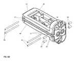
- FIG. 1is a perspective view of the expandable implant device of a preferred embodiment made in accordance with the present invention shown in a contracted non-expanded position.
- FIG. 2is a side view of the expandable implant device taken from FIG. 1 .
- FIG. 3Ais a perspective view of the device of FIG. 1 shown with the distal end expanded and the proximal end contracted.
- FIG. 3Bis a side view taken from FIG. 3A .
- FIG. 3Cis the side view taken from FIG. 3B with threaded fasteners installed in the proximal end of each first and second base plate.
- FIG. 4Ais a perspective view of the device of FIG. 1 shown with the proximal end expanded and the distal end contracted.
- FIG. 4Bis a side view taken from FIG. 4A .
- FIG. 4Cis a side view taken from FIG. 4B with threaded fasteners installed in the proximal end of each first and second base plate.
- FIG. 5Ais a perspective view of the device of FIG. 1 shown with the distal and the proximal end fully expanded.
- FIG. 5Bis a side view of the device taken from FIG. 5A .
- FIG. 5Cis a side view taken from FIG. 5B with threaded fasteners installed in the proximal end of each first and second base plate.
- FIG. 5Dis a perspective view of the device of FIG. 5A with threaded fasteners installed in the proximal end of each first and second base plate.
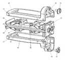
- FIG. 6Ais an exploded side view of the frame and ramp assemblies of the present invention as a first assembly step.
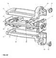
- FIG. 6Bis a perspective view of the assembled frame and ramp assemblies of FIG. 6A with the drive shafts and pins shown exploded as a second assembly step.
- FIG. 6Cis a perspective view of the assembled frame, ramp assemblies, drive shafts and pins of FIG. 6B with the base plates and locking tabs shown exploded as a third assembly step.
- FIG. 6Dis a perspective view of the assembled frame, ramp assemblies, drive shafts, pins, base plates and locking tabs of FIG. 6C with the final pins shown exploded as a fourth assembly step.
- FIG. 7Ais a front or proximal view of the device of the present invention shown in a contracted position.
- FIG. 7Bis a front or proximal view of the device of the present invention shown in an expanded position.
- FIG. 7Cis a front or proximal view of the device of the present invention shown in an expanded position with threaded fasteners installed in the proximal end of each first and second base plate and the locking tabs in an unlocked position.
- FIG. 7Dis a front or proximal view of the device of the present invention shown in an expanded position with threaded fasteners installed in the proximal end of each first and second base plate and the locking tabs in a locked position.
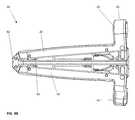
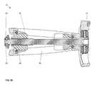
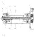
- FIG. 8Ais a side cross-sectional view of the device of the present invention with the distal drive shaft collapsed.
- FIG. 8Bis a side cross-sectional view of the device of the present invention with the proximal drive shaft collapsed.
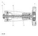
- FIG. 8Cis a side cross-sectional view of the device of the present invention with the distal drive shaft distally expanded.
- FIG. 8Dis a side cross-sectional view of the device of the present invention with the proximal drive shaft distally expanded.
- FIG. 8Eis a side cross-sectional view of the device of the present invention with the distal drive shaft proximally expanded.
- FIG. 8Fis a side cross-sectional view of the device of the present invention with the proximal drive shaft proximally expanded.
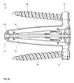
- FIG. 8Gis a side cross-sectional view of the device of the present invention with the distal drive shaft fully expanded.
- FIG. 8His a side cross-sectional view of the device of the present invention with the proximal drive shaft fully expanded.
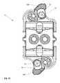
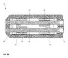
- FIG. 9Ais a top cross-sectional view of the device of the present invention in a contracted position.
- FIG. 9Bis a top cross-sectional view of the device of the present invention in a distally expanded position.
- FIG. 9Cis a top cross-sectional view of the device of the present invention in a proximally expanded position.
- FIG. 9Dis a top cross-sectional view of the device of the present invention in a fully expanded position.
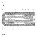
- FIG. 10Ais a top view of the device of the present invention in a contracted position.
- FIG. 10Bis a top view of the device of the present invention in a fully expanded position.
- FIG. 10Cis a top view of the device of the present invention in a fully expanded position with threaded fasteners installed in the proximal end of each first and second base plate.
- FIG. 11Ais a right cross-sectional view of the device of the present invention in a contracted position at the ramp dovetail feature.
- FIG. 11Bis a right cross-sectional view of the device of the present invention in an expanded position at the ramp dovetail feature.
- FIG. 12is a perspective view of the implant device of the present invention shown implanted between two vertebral bodies of a spine.
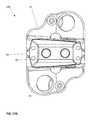
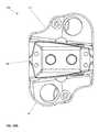
- FIG. 13is a front view taken from FIG. 12 of the implant device of the present invention shown implanted between two vertebral bodies of a spine.
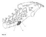
- FIG. 14is a perspective view of the implant device of the present invention shown implanted between two vertebral bodies of a spine.
- FIG. 15is a side view taken from FIG. 12 of the implant device of the present invention shown implanted between two vertebral bodies of a spine.
- FIG. 16is a side view of a first alternative embodiment showing the device made with one base plate and a frame.
- FIG. 17Ais an end view of a second alternative of the present invention having a laterally inclined outer surface of the base plates configured to mimic a lordotic curvature at a first lordotic angle less than or equal to 10 degrees.
- FIG. 17Bis a right section view of the second embodiment of FIG. 17A .
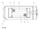
- FIG. 18Ais an end view of a second alternative of the present invention having a laterally inclined outer surface of the base plates configured to mimic a lordotic curvature at a first lordotic angle greater than 10 degrees.
- FIG. 18Bis a right section view of the second embodiment of FIG. 18A .
- FIG. 19Ais an end view of a second alternative of the present invention having a laterally inclined outer surface of the base plates configured to mimic a lordotic curvature at a first lordotic angle greater than 15 degrees.
- FIG. 19Bis a right section view of the second embodiment of FIG. 19A .
- the intervertebral implant device with independent distal-proximal expansion of the present inventionhereinafter described as an expandable interbody fusion implant device 10 , has a frame 60 , two ramp assemblies, 30 , 32 and two overlying base plates 20 , 40 driven by two independent drive shafts 50 , 52 ; as illustrated in FIG. 1 .
- the device 10shows the frame 60 having a distal end 62 and a proximal end 61 .
- the two ramp assemblies 30 , 32include a distal translating ramp 34 and a proximal translating ramp 35 respectively, and further have a first pivoting hinged ramp 31 and a second pivoting hinged ramp 33 .
- the two overlying base plates 20 , 40are disposed between the distal end 62 and the proximal end 61 .
- the first base plate 20overlies the second base plate 40 .
- Each base plate 20 , 40is hinged to a distal ramp assembly 30 and the proximal ramp assembly 32 at an end of one of the said pivoting hinged ramps of each ramp assembly.
- the two independently driven drive shafts 50 , 52include a first drive shaft 50 for translating the distal ramp assembly 30 and a second drive shaft 52 for translating the proximal ramp assembly 32 .
- Each drive shaft 50 , 52is affixed to the frame 60 at the distal and proximal end.
- each base plate 20 , 40respectively have end plates 21 and 41 . These end plates each are provided with a through hole 25 for receiving a threaded fastener 100 . Threaded fastener 100 is shown in FIG. 3C .
- the implant device 10is shown where the first drive shaft 50 has been rotated such that the distal ramp assembly 30 is moved towards the distal end of the frame 62 .
- the translating ramp 34 of the distal ramp assembly 30moves the pivoting hinged ramp 31 and 33 along an outer surface of the translating ramp 34 following the contour of the outer surface.
- this drive shaft 50is rotationally driven to rotate the distal end the base plates 20 , 40 both are increased in height from the contracted state to an expanded state. This increase in height can occur in small increments anywhere dependent on the amount of the rotation of the drive shaft 50 and this rotation achieves a maximum level when the pivoting hinged ramp hits a stop wall 36 on the translating ramp 34 .
- Threaded fasteners 100can be inserted through the through holes 25 in both the first end plate 21 and the second end plate 41 of the first base plate 20 and the second base plate 40 respectively at any stage/position.
- the implant device 10alternatively, can have the second drive shaft 52 rotated in such a fashion that the proximal end 61 of the implant 10 will be elevated from a contracted position shown in FIG. 1 to the expanded position as shown in FIGS. 4A-4C .
- the translating ramp 35 of the proximal ramp assembly 32is drawn toward the proximal end 61 of the frame 60 and as this occurs the pivoting hinged ramps 31 , 33 ride on the outer surface of the ramp 35 such that the first base plate 20 and the second base plate 40 are moved increasing in height at the proximal end 61 as illustrated. This occurs independent of the distal end of the implant 10 as the distal end has not moved and is in the contracted position as illustrated in this embodiment.
- This featureallows the surgeon the option to move the implant 10 near the distal end 62 into an expanded condition or, alternatively, near the proximal end 61 into an expanded position or can move each end of the implant 10 by whatever increment or amount the surgeon prefers to set a desired angular inclination between the opposing base plate 20 , 40 surfaces.
- the implant device 10is shown where both the first drive shaft 50 and the second drive shaft 52 have been rotated into a fully expanded position.
- the first base plate 20moves outwardly both distally and proximally as does the second base plate 40 move both distally and proximally.
- Both base plates 20 , 40will move equally as they are driven by the translating ramp 34 at the distal ramp assembly 30 and the translating ramp 35 of the proximal ramp assembly 32 assuming that the contours on both ramps 34 , 35 are made identical in surface contour and elevation.
- both drive shafts 50 , 52are turned in this position, the base plates 20 , 40 are moved relatively horizontal and parallel to each other which is more conventional to a common expandable implant device.
- a unique featureis that this expansion can be independently adjusted proximally and distally to achieve this position.
- One drive shaft 50 or 52can be rotated more or one less to create any desired inclination between a range of maximum full expansion and partially expanded and anywhere in between based on the rotational selection chosen for each drive shaft 50 , 52 by the surgeon.
- FIGS. 6A-6Dvarious exploded views of the components of the implant device 10 are shown.
- the ramp assemblies 30 , 32are shown as individual components, the translating ramps 34 , 35 and the pivoting hinged ramps 31 , 33 respectively are illustrated.
- the translating ramps 34 , 35have an outer contour 37 on both an upper and a lower surface of each translating ramp 34 , 35 and have a groove 38 on each ramp 34 , 35 . This groove 38 allows lateral sides of the pivoting hinged ramps 31 and 33 to enter in a dovetail configuration and lock into the translating ramps 34 , 35 .
- both the pivoting hinged ramps 31 , 33ride on the outer surface 37 of the translating ramps 34 and 35 respectively. In this fashion, during the elevation of the implant 10 from contracted to expanded, the pivoting hinged ramps 31 , 33 rest securely on the surface 37 on both lateral sides of the translating ramp 34 , 35 such that the base plates 20 , 40 hinged to the pivoting hinged ramps 31 , 33 at both lateral ends are fully supported across the lateral width of the implant device 10 .
- the frame 60shown slightly below the ramp assembly components, the frame 60 is a singular piece having a distal end 62 that has a tapered exterior surface to facilitate insertion.
- grooves 63are shown extending vertically, these grooves 63 are provided such that the end plates 21 , 41 on the first base plate 20 and second base plate 40 can be pinned and slidably moved within the grooves 63 or slots on the end plates 21 , 41 such that on expansion of the proximal end 61 the end plates 21 , 41 can pivot about pins 83 inserted through the end plates 21 , 41 .
- the pins 83engage the end plates 21 , 41 and are pressed into holes 23 provided in each end plate 21 , 41 .
- holes 23 and pins 83are shown such that the pins 83 extend sufficiently inwardly to be captured within the slot or groove 63 in the proximal end 61 .
- FIG. 6Bare a pair of drive shaft pins 82 , these drive shaft pins 82 extend through the holes 28 in the distal end of the frame 60 . These holes 28 extend across the frame 60 in such a fashion that the distal pins 82 will engage grooves 53 , shown in FIG. 6B , at the distal end of the drive shafts 50 , 52 .
- pins 85are pushed through holes in the end plate 64 and will lock into grooves 55 at the proximal end of the drive shafts 50 , 52 .
- the ramp assemblies 30 , 32 and drive shafts 50 , 52are shown affixed to the frame 60 with the first base plate 20 and second base plate 40 shown above that assembly.
- a locking means or tab 70is illustrated that is affixed into an opening 29 and 49 in the two opposing end plates 21 and 41 , respectively. These locking tabs 70 , when rotated over the head of the fastener 100 , prevent the fastener 100 from backing out. This effectively completes the assembly of the implant device 10 .
- the pivoting hinged ramps 31 , 33are pinned to the base plates 20 , 40 through holes 27 in the base plates and holes 22 in the pivoting hinged ramps with pins 80 , 81 .
- FIGS. 7A-7Dend views of the implant device 10 are illustrated.
- the implant device 10is shown in the fully contracted position.
- the implant device 10at the proximal end 61 , shows the fastener openings 25 with the locking tab 70 projecting over a portion of the fastener opening hole 25 .
- the fasteners 100have yet to be inserted into place and could not be until the locking tab 70 is moved into an open position.
- FIG. 7Bthe implant device 10 is shown in a fully expanded position as compared to FIG. 7A wherein the implant 10 was shown in the contracted position.
- the fasteners 100can be inserted through the openings 25 wherein they can be delivered to and fastened to the two vertebral bodies.
- the locking tab 70is rotated with a drive tool, not shown, and the star shaped recess 72 so the opening 25 is fully exposed to allow the head of the fastener 100 to be inserted into the hole opening 25 on insertion.
- the locking tab 70is then shown in the locked position, rotated and covering at least partially the hole opening 25 , thereby preventing the fastener 100 from loosening and backing out once inserted and threaded into the vertebral body.
- FIGS. 8A-8Hvarious cross-sectional views of the implant device 10 are illustrated. These cross-sectional views are taken down the longitudinal length of the device 10 in such a way that either the proximal drive shaft 50 or the distal drive shaft 52 is shown, the cross section taken through the middle of the respective drive shaft 50 , 52 .
- the distal drive shaft 52is shown with the implant device 10 in the fully contracted position.
- the pivoting hinged ramps 31 , 33are shown at the lowest height on the contoured surfaces 37 of the translating ramps 34 , 35 of ramp assembly 30 , 32 respectively.
- the pivoting hinged ramps 31 , 33ride on the exterior surface 37 of the translating ramps 34 , 35 and in the contracted position are fully contained and pinned to the respective base plates, 20 , 40 .
- the pins 82 holding the distal end of the drive shafts 50 , 52are shown holding the drive shafts in place at the distal end 62
- the pins 85 shown extending through the end plate 64 of the frame 60are shown holding the drive shafts 50 , 52 at the proximal end 61 .
- There is a drive opening 55shown as a star shaped recess, provided at the proximal end such that the rotation of each drive shaft 50 , 52 can be accomplished by the insertion of a drive tool, not illustrated.
- threads 59are shown in engagement with complimentary female threads 94 on the translating ramp 34 to be moved. As shown in the contracted position, these threads 94 are fully inside the translating ramp 34 .
- the proximal drive shaft 50is illustrated having the threads 58 fully engaged in the threads 95 of the proximal ramp 35 , again, this is in the fully contracted position, as previously discussed in reference to FIG. 8A .
- the translating ramp 34when the implant 10 is expanded at the distal end 62 , the translating ramp 34 is moved progressively towards the distal end 62 of the frame 60 and as it moves toward the end of the frame 60 , the pivoting hinged ramps 31 , 33 slide up the contour on the exterior surface 37 of the translating ramp 34 elevating the base plates 20 , 40 respectively.
- the translating ramps 34 , 35are equally contoured, therefore, when the drive shaft 52 is rotated and the threads 59 drive the translating ramp 34 toward the distal end 62 , the base plates 20 , 40 move equally expanding away from the fully contracted position.
- the implant 10is shown with the proximal end 61 expanded and the distal end 62 contracted.
- the distal translating ramp 34is shown in the contracted position with the threads 59 from the distal drive 52 shaft still fully engaged in threads 94 inside the translating ramp 34 .
- proximal drive shaft 50when the proximal drive shaft 50 is rotated, it drives the proximal translating ramp 35 towards the proximal end 61 of the implant 10 as the threads push it toward the proximal end of the implant 10 elevating the base plates 20 , 40 and as previously discussed, since the ramps 34 , 35 are symmetrical in this configuration both base plates 20 , 40 move equally apart at the proximal end 61 . Interestingly, when this occurs, you will notice that the end plates 21 , 41 being integral to the base plates 20 , 40 will elevate accordingly, as this occurs, they slide and rotate on the same inclination as the base plates. With reference to FIGS.
- the outer surface of the base plates 20 , 40have an angle mimicking the lordotic curvature of the lumbar spine at multiple angles, as will be discussed with reference to FIGS. 17A-19B .
- the distal ramp assembly 30is fully moved toward the expanded position when the distal translating ramp 34 is moved toward the distal end 62 of the implant 10 .
- the proximal ramp assembly 35is moved toward the proximal end 61 of the implant 10 . Since they are both moved, the pivoting hinged ramps 31 , 33 are elevated by riding on the contoured surface 37 of the translating ramps 34 , 35 increasing the height of the implant device 10 to the fully expanded position as shown in FIG. 8H .
- FIG. 9A-9Dtop cross sectional views are shown to facilitate an understanding of the ramp assemblies 30 , 32 .
- the translating ramps 34 , 35are shown in the contracted position, thus are spaced away from the distal 62 and proximal 61 ends, as illustrated. In such a configuration, the threads 58 , 59 on each drive shaft 50 , 52 are fully encased within their respective translating ramps 34 , 35 .
- FIG. 9Bwhen the distal end 62 is elevated from the contracted position as shown in FIG.
- FIG. 9Ashows the drive shaft 52 with the threads 59 partially exposed wherein the translating ramp 34 at the distal end 62 is moved distally, almost into contact with the frame 60 at the distal end 62 .
- FIG. 9Cshows the alternate configuration where the translating ramp 35 is moved toward the proximal end 61 of the implant 10 and the distal translating ramp 34 is shown in the contracted position.
- FIG. 9Din the fully expanded configuration, both translating ramps 34 , 35 are shown moved toward the distal 62 and proximal 61 ends and not spaced therefrom.
- FIGS. 10A-10Can outline drawing of the implant device 10 from a top view is shown.
- the device 10is in a fully contracted position
- the top view of FIG. 10Bshows the device in a fully expanded position
- the implant device 10is shown with threaded fasteners 100 inserted in the hole openings 25 . It is hoped that these additional views showing how the device 10 is actually positioned during the various stages of inclination and various conditions from contracted to fully expanded and the ability of the device 10 to be distally expanded independent of proximal expansion and proximally expanded independent of distal expansion has been shown throughout the various views previously discussed.
- FIGS. 11A and 11Bcross sectional views of the ramp assemblies 30 , 32 are shown contained in the frame 60 and base plates 20 , 40 .
- the implant device 10is shown in a fully contracted position, when this occurs, the implant device 10 shows the pivoting hinged ramps 31 , 33 with the groove 38 shown as a dovetail feature that interlocks the lateral sides of the pivoting hinged ramps 31 , 33 projecting inwardly the dovetail or groove 38 of the translating ramp 34 , 35 as illustrated. When this occurs, it locks the ramp from moving laterally.
- the base plates 20 , 40further provide a constraint on movement of the translating ramps 34 , 35 to which the pivoting hinged ramps 31 , 33 are attached.
- the pivoting hinged ramp 31 , 33is shown in the elevated or expanded position, an important aspect of the present invention as illustrated is that even in the fully expanded position, it is noticed that the pivoting hinged ramps 31 , 33 are fully supported on both sides by the translating ramps 34 , 35 .
- Thisprovides lateral stability for the base plates 20 , 40 that are hinged to the pivoting hinged ramps 31 , 33 on each lateral side. This means that the rigidity of the device 10 is extremely secure and the device 10 is unlikely to flex or twist.
- FIGS. 12-15the implant device 10 is shown inserted between two adjacent vertebral bodies 2 , 4 on implantation. As illustrated in FIGS. 12 and 13 , it is clearly shown how the device 10 will be implanted. FIG. 14 , similarly shows a different perspective view of the implanted device 10 . FIG. 15 , on a head-on view, shows that most of the device 10 is hidden by the disc space when inserted in between the vertebral bodies 2 , 4 .
- top views of the implant device 10are illustrated, it is important to understand that the top and bottom views are virtually identical and that the base plates 20 , 40 provide a perimeter frame with a large opening or aperture 12 .
- the device 10When the device 10 is in the expanded position either proximally or distally one of the translating ramps 34 , 34 will move making the aperture or opening space 12 between the base plates 20 , 40 extremely large.
- both translating ramps 34 , 35When both translating ramps 34 , 35 are moved into the expanded position this aperture space is increased even further.
- endplates 21 , 41While the present invention has been shown with endplates 21 , 41 , these end plates could be removed and the implant device 10 would no longer be a standalone device which can be inserted and then fastened directly into the vertebral bodies, but may have a separate vertebral plate that can be added if these end plates are not provided.
- the preferred device 10is shown where the base plates are provided on both an upper and a lower surface.
- device 10 Ait is understood that one base plate could be provided only and that the frame itself would be a stationary base plate. In such a condition either the base plate 20 or base plate 40 could be removed and only one provided, as shown in FIG. 16 .
- the angular inclination of the device 10 , 10 Ais only limited by the maximum height that the device can be expanded.
- the deviceis only limited by the shape and contours of the ramps. As noted, the ramps have a radius contour or curved contour such that it increases rapidly at initial movement from a contracted position and this rate of movement changes as the ramp achieves the peak of the curvature.
- any inclination between contracted and fully expandedcan be established by simply stopping the rotation of the drive shaft.
- the drive shaftwill maintain its position regardless of where it is stopped. Therefore, the surgeon can pick precisely the location he wants to elevate the proximal or distal end independent of the other such that any inclination can be achieved with the range of that provided by the threads on the ramp and drive shaft and the contour surface of the ramps themselves.
- the present inventioncan be made in a variety of sizes, by way of example, widths: 18 mm and 22 mm; longitudinal lengths: 40, 45, 50, 55, and 60 mm; Distal and Proximal end height: 8 mm; Center height range: 9 mm (contracted)-15 mm (expanded); Maximum distal or proximal angle: 40 mm length: 10°; 45 mm length: 9°; 50 mm length: 8°; 55 mm length: 7°; 60 mm length: 6°.
- FIGS. 17A-19Ba second alternative embodiment 10B is shown having a laterally inclined outer surface of the base plates 20 , 40 configured to mimic a lordotic curvature of the lumbar spine.
- FIGS. 17A-17Billustrate a 7° Lordosis-Anterior (tall side) height range: 10 mm-16 mm
- FIGS. 18A-18Billustrate a 14° Lordosis-Anterior (tall side) height range: 12 mm-18 mm
- FIGS. 19A-19Billustrate a 21° Lordosis-Anterior (tall side) height range: 14 mm-20 mm.
- the effective anglesare achieved by changing the thickness of the left or anterior side of the base plates relative to the right side of the base plates.
Landscapes
- Health & Medical Sciences (AREA)
- Engineering & Computer Science (AREA)
- Biomedical Technology (AREA)
- Neurology (AREA)
- Orthopedic Medicine & Surgery (AREA)
- Cardiology (AREA)
- Oral & Maxillofacial Surgery (AREA)
- Transplantation (AREA)
- Heart & Thoracic Surgery (AREA)
- Vascular Medicine (AREA)
- Life Sciences & Earth Sciences (AREA)
- Animal Behavior & Ethology (AREA)
- General Health & Medical Sciences (AREA)
- Public Health (AREA)
- Veterinary Medicine (AREA)
- Prostheses (AREA)
Abstract
Description
Claims (10)
Priority Applications (4)
| Application Number | Priority Date | Filing Date | Title |
|---|---|---|---|
| US15/363,392US9750618B1 (en) | 2016-11-29 | 2016-11-29 | Intervertebral implant device with independent distal-proximal expansion |
| US15/645,575US10758366B2 (en) | 2016-11-29 | 2017-07-10 | Intervertebral implant device with independent distal-proximal expansion |
| US15/645,609US10709572B2 (en) | 2016-11-29 | 2017-07-10 | Intervertebral implant device with independent distal-proximal expansion |
| US16/936,235US20200345511A1 (en) | 2016-11-29 | 2020-07-22 | Intervertebral implant device with independent distal-proximal expansion |
Applications Claiming Priority (1)
| Application Number | Priority Date | Filing Date | Title |
|---|---|---|---|
| US15/363,392US9750618B1 (en) | 2016-11-29 | 2016-11-29 | Intervertebral implant device with independent distal-proximal expansion |
Related Child Applications (2)
| Application Number | Title | Priority Date | Filing Date |
|---|---|---|---|
| US15/645,575ContinuationUS10758366B2 (en) | 2016-11-29 | 2017-07-10 | Intervertebral implant device with independent distal-proximal expansion |
| US15/645,609DivisionUS10709572B2 (en) | 2016-11-29 | 2017-07-10 | Intervertebral implant device with independent distal-proximal expansion |
Publications (1)
| Publication Number | Publication Date |
|---|---|
| US9750618B1true US9750618B1 (en) | 2017-09-05 |
Family
ID=59701421
Family Applications (4)
| Application Number | Title | Priority Date | Filing Date |
|---|---|---|---|
| US15/363,392Expired - Fee RelatedUS9750618B1 (en) | 2016-11-29 | 2016-11-29 | Intervertebral implant device with independent distal-proximal expansion |
| US15/645,575Expired - Fee RelatedUS10758366B2 (en) | 2016-11-29 | 2017-07-10 | Intervertebral implant device with independent distal-proximal expansion |
| US15/645,609Expired - Fee RelatedUS10709572B2 (en) | 2016-11-29 | 2017-07-10 | Intervertebral implant device with independent distal-proximal expansion |
| US16/936,235AbandonedUS20200345511A1 (en) | 2016-11-29 | 2020-07-22 | Intervertebral implant device with independent distal-proximal expansion |
Family Applications After (3)
| Application Number | Title | Priority Date | Filing Date |
|---|---|---|---|
| US15/645,575Expired - Fee RelatedUS10758366B2 (en) | 2016-11-29 | 2017-07-10 | Intervertebral implant device with independent distal-proximal expansion |
| US15/645,609Expired - Fee RelatedUS10709572B2 (en) | 2016-11-29 | 2017-07-10 | Intervertebral implant device with independent distal-proximal expansion |
| US16/936,235AbandonedUS20200345511A1 (en) | 2016-11-29 | 2020-07-22 | Intervertebral implant device with independent distal-proximal expansion |
Country Status (1)
| Country | Link |
|---|---|
| US (4) | US9750618B1 (en) |
Cited By (67)
| Publication number | Priority date | Publication date | Assignee | Title |
|---|---|---|---|---|
| US10052215B2 (en)* | 2016-06-29 | 2018-08-21 | Globus Medical, Inc. | Expandable fusion device and method of installation thereof |
| EP3482723A1 (en)* | 2017-11-09 | 2019-05-15 | Globus Medical, Inc. | Expandable intervertebral implant |
| WO2019126213A1 (en)* | 2017-12-18 | 2019-06-27 | Nuvasive, Inc. | Expandable implant device |
| WO2019170739A1 (en)* | 2018-03-06 | 2019-09-12 | Eit Emerging Implant Technologies Gmbh | Intervertebral cages with integrated expansion and angular adjustment mechanism |
| JP2020032189A (en)* | 2018-08-29 | 2020-03-05 | グローバス メディカル インコーポレイティッド | Expandable intervertebral implant |
| US10709574B2 (en)* | 2012-04-13 | 2020-07-14 | Neuropro Technologies, Inc. | Bone fusion device |
| US10722379B2 (en) | 2017-11-09 | 2020-07-28 | Globus Medical, Inc. | Expandable intervertebral implant |
| US10729560B2 (en) | 2017-01-18 | 2020-08-04 | Neuropro Technologies, Inc. | Bone fusion system, device and method including an insertion instrument |
| US10779957B2 (en)* | 2010-09-03 | 2020-09-22 | Globus Medical, Inc. | Expandable fusion device and method of installation thereof |
| US10973657B2 (en) | 2017-01-18 | 2021-04-13 | Neuropro Technologies, Inc. | Bone fusion surgical system and method |
| US11141289B2 (en) | 2017-01-18 | 2021-10-12 | Neuropro Technologies, Inc. | Bone fusion system, device and method including delivery apparatus |
| US11154404B2 (en)* | 2016-09-08 | 2021-10-26 | Mayo Foundation For Medical Education And Research | Spinal fixation system |
| US11285014B1 (en) | 2020-11-05 | 2022-03-29 | Warsaw Orthopedic, Inc. | Expandable inter-body device, system, and method |
| US11291554B1 (en) | 2021-05-03 | 2022-04-05 | Medtronic, Inc. | Unibody dual expanding interbody implant |
| US20220133493A1 (en)* | 2020-11-05 | 2022-05-05 | Warsaw Orthopedic, Inc. | Expandable inter-body device, system and method |
| EP4000564A1 (en)* | 2020-11-20 | 2022-05-25 | Zimmer Biomet Spine, Inc. | Expandable intervertebral implant with independent adjustments |
| US11344424B2 (en) | 2017-06-14 | 2022-05-31 | Medos International Sarl | Expandable intervertebral implant and related methods |
| EP3939548A4 (en)* | 2020-05-22 | 2022-06-08 | Hilo Innovations, Llc | Expandable cage for spine and method for inserting same |
| US11376134B1 (en) | 2020-11-05 | 2022-07-05 | Warsaw Orthopedic, Inc. | Dual expanding spinal implant, system, and method of use |
| US20220211515A1 (en)* | 2020-06-15 | 2022-07-07 | Nofusco Corporation | Intravertebral implant system and methods of use |
| US11395743B1 (en) | 2021-05-04 | 2022-07-26 | Warsaw Orthopedic, Inc. | Externally driven expandable interbody and related methods |
| US11399956B2 (en) | 2013-03-15 | 2022-08-02 | Neuropro Technologies, Inc. | Bodiless bone fusion device, apparatus and method |
| US11426286B2 (en) | 2020-03-06 | 2022-08-30 | Eit Emerging Implant Technologies Gmbh | Expandable intervertebral implant |
| US11426290B2 (en) | 2015-03-06 | 2022-08-30 | DePuy Synthes Products, Inc. | Expandable intervertebral implant, system, kit and method |
| US11432940B2 (en) | 2011-08-09 | 2022-09-06 | Neuropro Technologies, Inc. | Bone fusion device, system and method |
| US11446156B2 (en) | 2018-10-25 | 2022-09-20 | Medos International Sarl | Expandable intervertebral implant, inserter instrument, and related methods |
| US11446155B2 (en)* | 2017-05-08 | 2022-09-20 | Medos International Sarl | Expandable cage |
| US11452607B2 (en) | 2010-10-11 | 2022-09-27 | DePuy Synthes Products, Inc. | Expandable interspinous process spacer implant |
| US11452616B2 (en) | 2011-08-09 | 2022-09-27 | Neuropro Spinal Jaxx, Inc. | Bone fusion device, apparatus and method |
| US11458029B2 (en) | 2017-01-18 | 2022-10-04 | Neuropro Technologies, Inc. | Bone fusion system, device and method including a measuring mechanism |
| WO2022216564A1 (en)* | 2021-04-04 | 2022-10-13 | Nuvasive, Inc. | Expandable spinal fusion implants and insertion devices |
| WO2022216539A1 (en)* | 2021-04-04 | 2022-10-13 | Nuvasive, Inc. | Expandable implants |
| US11497619B2 (en) | 2013-03-07 | 2022-11-15 | DePuy Synthes Products, Inc. | Intervertebral implant |
| US11510788B2 (en) | 2016-06-28 | 2022-11-29 | Eit Emerging Implant Technologies Gmbh | Expandable, angularly adjustable intervertebral cages |
| US11517443B2 (en) | 2020-11-05 | 2022-12-06 | Warsaw Orthopedic, Inc. | Dual wedge expandable implant, system and method of use |
| US11583414B2 (en) | 2004-11-03 | 2023-02-21 | Neuropro Technologies, Inc. | Bone fusion device |
| US11596522B2 (en) | 2016-06-28 | 2023-03-07 | Eit Emerging Implant Technologies Gmbh | Expandable and angularly adjustable intervertebral cages with articulating joint |
| US11612499B2 (en) | 2021-06-24 | 2023-03-28 | Warsaw Orthopedic, Inc. | Expandable interbody implant |
| US11622868B2 (en) | 2007-06-26 | 2023-04-11 | DePuy Synthes Products, Inc. | Highly lordosed fusion cage |
| US11638653B2 (en) | 2020-11-05 | 2023-05-02 | Warsaw Orthopedic, Inc. | Surgery instruments with a movable handle |
| US11712345B2 (en) | 2006-12-07 | 2023-08-01 | DePuy Synthes Products, Inc. | Intervertebral implant |
| US11723778B1 (en) | 2021-09-23 | 2023-08-15 | Nofusco Corporation | Vertebral implant system and methods of use |
| US11730608B2 (en) | 2021-07-13 | 2023-08-22 | Warsaw Orthopedic, Inc. | Monoblock expandable interbody implant |
| US11752009B2 (en) | 2021-04-06 | 2023-09-12 | Medos International Sarl | Expandable intervertebral fusion cage |
| US11806250B2 (en) | 2018-02-22 | 2023-11-07 | Warsaw Orthopedic, Inc. | Expandable spinal implant system and method of using same |
| EP4272709A1 (en)* | 2022-05-04 | 2023-11-08 | Globus Medical, Inc. | Expandable fusion device and installation device therefor |
| US11833059B2 (en) | 2020-11-05 | 2023-12-05 | Warsaw Orthopedic, Inc. | Expandable inter-body device, expandable plate system, and associated methods |
| US11850160B2 (en) | 2021-03-26 | 2023-12-26 | Medos International Sarl | Expandable lordotic intervertebral fusion cage |
| US11850163B2 (en) | 2022-02-01 | 2023-12-26 | Warsaw Orthopedic, Inc. | Interbody implant with adjusting shims |
| US11872139B2 (en) | 2010-06-24 | 2024-01-16 | DePuy Synthes Products, Inc. | Enhanced cage insertion assembly |
| US11883300B2 (en) | 2020-06-15 | 2024-01-30 | Nofusco Corporation | Orthopedic implant system and methods of use |
| US11918489B2 (en) | 2021-04-02 | 2024-03-05 | Nuvasive Inc. | Expansion driver |
| US11963881B2 (en) | 2020-11-05 | 2024-04-23 | Warsaw Orthopedic, Inc. | Expandable inter-body device, system, and method |
| USRE49973E1 (en) | 2013-02-28 | 2024-05-21 | DePuy Synthes Products, Inc. | Expandable intervertebral implant, system, kit and method |
| US12011361B2 (en) | 2008-04-05 | 2024-06-18 | DePuy Synthes Products, Inc. | Expandable intervertebral implant |
| US12090064B2 (en) | 2022-03-01 | 2024-09-17 | Medos International Sarl | Stabilization members for expandable intervertebral implants, and related systems and methods |
| US12097124B2 (en) | 2009-03-30 | 2024-09-24 | DePuy Synthes Products, Inc. | Zero profile spinal fusion cage |
| US12121453B2 (en) | 2020-11-05 | 2024-10-22 | Warsaw Orthopedic, Inc. | Dual wedge expandable implant with eyelets, system, and method of use |
| US12144742B2 (en) | 2020-06-15 | 2024-11-19 | Foundation Surgical Group, Inc. | Implant system and methods of use |
| US12171439B2 (en) | 2020-11-05 | 2024-12-24 | Warsaw Orthopedic, Inc. | Protected drill |
| US12239544B2 (en) | 2020-11-05 | 2025-03-04 | Warsaw Orthopedic, Inc. | Rhomboid shaped implants |
| US12268614B2 (en) | 2021-06-24 | 2025-04-08 | Warsaw Orthopedic, Inc. | Interbody implant with adjusting shims |
| US12295865B2 (en) | 2021-06-24 | 2025-05-13 | Warsaw Orthopedic, Inc. | Expandable interbody implant and corresponding inserter |
| US12318307B2 (en) | 2021-07-16 | 2025-06-03 | Blue Ocean Spine Gmbh | Adjustable spinal implants, associated instruments and methods |
| US12318308B2 (en) | 2020-11-05 | 2025-06-03 | Warsaw Orthopedic, Inc. | Dual expandable inter-body device |
| US12414863B2 (en) | 2021-06-24 | 2025-09-16 | Warsaw Orthopedic, Inc. | Expandable interbody implant and corresponding surgical tool |
| US12440346B2 (en) | 2023-03-31 | 2025-10-14 | DePuy Synthes Products, Inc. | Expandable intervertebral implant |
Families Citing this family (7)
| Publication number | Priority date | Publication date | Assignee | Title |
|---|---|---|---|---|
| US10786367B2 (en)* | 2016-07-21 | 2020-09-29 | Seaspine, Inc. | Expandable implant |
| AU2017228529B2 (en)* | 2016-09-12 | 2022-03-10 | Vb Spine Us Opco Llc | Interbody implant with independent control of expansion at multiple locations |
| EP4171448A4 (en)* | 2020-07-20 | 2025-02-12 | Integrity Implants Inc. | EXPANDABLE FUSION DEVICE WITH INDEPENDENT EXPANSION SYSTEMS |
| NL2026145B1 (en)* | 2020-07-27 | 2022-03-29 | Am Solutions Holding B V | Expandable implant, implant system, kit of parts for assembling an expandable implant, and method of placing an implant in a bone |
| CN112353528B (en)* | 2020-10-20 | 2022-05-24 | 广东施泰宝医疗科技有限公司 | Side access fusion cage with integrally fixed adjustable height |
| CN116490150A (en)* | 2020-11-05 | 2023-07-25 | 华沙整形外科股份有限公司 | Expandable interbody device and system |
| US20230363923A1 (en)* | 2022-05-11 | 2023-11-16 | Teslake, Inc. | Reversibly, proximally, and distally expandable spinal cage |
Citations (20)
| Publication number | Priority date | Publication date | Assignee | Title |
|---|---|---|---|---|
| US196117A (en) | 1877-10-16 | Improvement in hoisting-jacks | ||
| US5658335A (en) | 1995-03-09 | 1997-08-19 | Cohort Medical Products Group, Inc. | Spinal fixator |
| US6641614B1 (en) | 1997-05-01 | 2003-11-04 | Spinal Concepts, Inc. | Multi-variable-height fusion device |
| US6723126B1 (en) | 2002-11-01 | 2004-04-20 | Sdgi Holdings, Inc. | Laterally expandable cage |
| US20060253201A1 (en)* | 2004-11-03 | 2006-11-09 | Mcluen Design, Inc. | Bone fusion device |
| US20070270968A1 (en)* | 2004-02-10 | 2007-11-22 | Baynham Bret O | Plif opposing wedge ramp |
| US20090210062A1 (en)* | 2008-02-20 | 2009-08-20 | John Thalgott | Orthopaedic Implants and Prostheses |
| US7708779B2 (en) | 2006-05-01 | 2010-05-04 | Warsaw Orthopedic, Inc. | Expandable intervertebral spacers and methods of use |
| US7854766B2 (en) | 2004-05-13 | 2010-12-21 | Moskowitz Nathan C | Artificial total lumbar disc for unilateral safe and simple posterior placement in the lumbar spine, and removable bifunctional screw which drives vertical sliding expansile plate expansion, and interplate widening, and angled traction spikes |
| US8231681B2 (en) | 2006-04-27 | 2012-07-31 | Warsaw Orthopedic | Self-contained expandable implant and method |
| US8303663B2 (en) | 2009-07-22 | 2012-11-06 | Spinex Tec, Llc | Methods and apparatuses for vertebral body distraction and fusion employing a coaxial screw gear sleeve mechanism |
| US8628577B1 (en) | 2009-03-19 | 2014-01-14 | Ex Technology, Llc | Stable device for intervertebral distraction and fusion |
| US8679183B2 (en) | 2010-06-25 | 2014-03-25 | Globus Medical | Expandable fusion device and method of installation thereof |
| US8696751B2 (en) | 2008-12-10 | 2014-04-15 | Coalign Innovations, Inc. | Adjustable distraction cage with linked locking mechanisms |
| US8940049B1 (en) | 2014-04-01 | 2015-01-27 | Ex Technology, Llc | Expandable intervertebral cage |
| US8986386B2 (en) | 2009-03-12 | 2015-03-24 | Vexim Sas | Apparatus for bone restoration of the spine and methods of use |
| DE102013113168A1 (en) | 2013-11-28 | 2015-06-11 | Humantech Germany Gmbh | Vertebral body replacement implant with worm gear |
| US9078769B2 (en) | 2010-02-02 | 2015-07-14 | Azadeh Farin | Spine surgery device |
| US20150272743A1 (en)* | 2014-04-01 | 2015-10-01 | Ex Technology, Llc | Expandable intervertebral cage |
| US20160250034A1 (en)* | 2013-10-31 | 2016-09-01 | Nlt Spine Ltd. | Adjustable implant |
Family Cites Families (2)
| Publication number | Priority date | Publication date | Assignee | Title |
|---|---|---|---|---|
| WO2016069796A1 (en) | 2014-10-28 | 2016-05-06 | Spectrum Spine Ip Holdings, Llc | Expandable, adjustable inter-body fusion devices and methods |
| US10369004B2 (en)* | 2015-12-16 | 2019-08-06 | Globus Medical, Inc. | Expandable intervertebralspacer |
- 2016
- 2016-11-29USUS15/363,392patent/US9750618B1/ennot_activeExpired - Fee Related
- 2017
- 2017-07-10USUS15/645,575patent/US10758366B2/ennot_activeExpired - Fee Related
- 2017-07-10USUS15/645,609patent/US10709572B2/ennot_activeExpired - Fee Related
- 2020
- 2020-07-22USUS16/936,235patent/US20200345511A1/ennot_activeAbandoned
Patent Citations (25)
| Publication number | Priority date | Publication date | Assignee | Title |
|---|---|---|---|---|
| US196117A (en) | 1877-10-16 | Improvement in hoisting-jacks | ||
| US5658335A (en) | 1995-03-09 | 1997-08-19 | Cohort Medical Products Group, Inc. | Spinal fixator |
| US6641614B1 (en) | 1997-05-01 | 2003-11-04 | Spinal Concepts, Inc. | Multi-variable-height fusion device |
| US6723126B1 (en) | 2002-11-01 | 2004-04-20 | Sdgi Holdings, Inc. | Laterally expandable cage |
| US20070270968A1 (en)* | 2004-02-10 | 2007-11-22 | Baynham Bret O | Plif opposing wedge ramp |
| US7854766B2 (en) | 2004-05-13 | 2010-12-21 | Moskowitz Nathan C | Artificial total lumbar disc for unilateral safe and simple posterior placement in the lumbar spine, and removable bifunctional screw which drives vertical sliding expansile plate expansion, and interplate widening, and angled traction spikes |
| US20060253201A1 (en)* | 2004-11-03 | 2006-11-09 | Mcluen Design, Inc. | Bone fusion device |
| US8231681B2 (en) | 2006-04-27 | 2012-07-31 | Warsaw Orthopedic | Self-contained expandable implant and method |
| US8579979B2 (en) | 2006-05-01 | 2013-11-12 | Warsaw Orthopedic, Inc. | Expandable intervertebral spacers and methods of use |
| US7708779B2 (en) | 2006-05-01 | 2010-05-04 | Warsaw Orthopedic, Inc. | Expandable intervertebral spacers and methods of use |
| US8257442B2 (en) | 2006-05-01 | 2012-09-04 | Warsaw Orthopedic, Inc. | Expandable intervertebral spacers and methods of use |
| US20090210062A1 (en)* | 2008-02-20 | 2009-08-20 | John Thalgott | Orthopaedic Implants and Prostheses |
| US8696751B2 (en) | 2008-12-10 | 2014-04-15 | Coalign Innovations, Inc. | Adjustable distraction cage with linked locking mechanisms |
| US8986386B2 (en) | 2009-03-12 | 2015-03-24 | Vexim Sas | Apparatus for bone restoration of the spine and methods of use |
| US8628577B1 (en) | 2009-03-19 | 2014-01-14 | Ex Technology, Llc | Stable device for intervertebral distraction and fusion |
| US9358125B2 (en) | 2009-07-22 | 2016-06-07 | Spinex Tec, Llc | Coaxial screw gear sleeve mechanism |
| US8303663B2 (en) | 2009-07-22 | 2012-11-06 | Spinex Tec, Llc | Methods and apparatuses for vertebral body distraction and fusion employing a coaxial screw gear sleeve mechanism |
| US9474626B2 (en) | 2009-07-22 | 2016-10-25 | Spinex Tec Llc | Methods and apparatuses for vertebral body distraction and fusion employing a coaxial screw gear sleeve mechanism |
| US9078769B2 (en) | 2010-02-02 | 2015-07-14 | Azadeh Farin | Spine surgery device |
| US8679183B2 (en) | 2010-06-25 | 2014-03-25 | Globus Medical | Expandable fusion device and method of installation thereof |
| US20160250034A1 (en)* | 2013-10-31 | 2016-09-01 | Nlt Spine Ltd. | Adjustable implant |
| DE102013113168A1 (en) | 2013-11-28 | 2015-06-11 | Humantech Germany Gmbh | Vertebral body replacement implant with worm gear |
| US8940049B1 (en) | 2014-04-01 | 2015-01-27 | Ex Technology, Llc | Expandable intervertebral cage |
| US20150272743A1 (en)* | 2014-04-01 | 2015-10-01 | Ex Technology, Llc | Expandable intervertebral cage |
| US20160262907A1 (en) | 2014-04-01 | 2016-09-15 | Ex Technology, Llc | Expandable intervertebral cage |
Cited By (108)
| Publication number | Priority date | Publication date | Assignee | Title |
|---|---|---|---|---|
| US11583414B2 (en) | 2004-11-03 | 2023-02-21 | Neuropro Technologies, Inc. | Bone fusion device |
| US11712345B2 (en) | 2006-12-07 | 2023-08-01 | DePuy Synthes Products, Inc. | Intervertebral implant |
| US11622868B2 (en) | 2007-06-26 | 2023-04-11 | DePuy Synthes Products, Inc. | Highly lordosed fusion cage |
| US12011361B2 (en) | 2008-04-05 | 2024-06-18 | DePuy Synthes Products, Inc. | Expandable intervertebral implant |
| US12097124B2 (en) | 2009-03-30 | 2024-09-24 | DePuy Synthes Products, Inc. | Zero profile spinal fusion cage |
| US11872139B2 (en) | 2010-06-24 | 2024-01-16 | DePuy Synthes Products, Inc. | Enhanced cage insertion assembly |
| US10779957B2 (en)* | 2010-09-03 | 2020-09-22 | Globus Medical, Inc. | Expandable fusion device and method of installation thereof |
| US11452607B2 (en) | 2010-10-11 | 2022-09-27 | DePuy Synthes Products, Inc. | Expandable interspinous process spacer implant |
| US11432940B2 (en) | 2011-08-09 | 2022-09-06 | Neuropro Technologies, Inc. | Bone fusion device, system and method |
| US11452616B2 (en) | 2011-08-09 | 2022-09-27 | Neuropro Spinal Jaxx, Inc. | Bone fusion device, apparatus and method |
| US10709574B2 (en)* | 2012-04-13 | 2020-07-14 | Neuropro Technologies, Inc. | Bone fusion device |
| US11439517B2 (en) | 2012-04-13 | 2022-09-13 | Neuropro Technologies, Inc. | Bone fusion device |
| USRE49973E1 (en) | 2013-02-28 | 2024-05-21 | DePuy Synthes Products, Inc. | Expandable intervertebral implant, system, kit and method |
| US11497619B2 (en) | 2013-03-07 | 2022-11-15 | DePuy Synthes Products, Inc. | Intervertebral implant |
| US12409050B2 (en) | 2013-03-15 | 2025-09-09 | Neuropro Technologies, Inc. | Bone fusion device, apparatus and method |
| US11963884B2 (en) | 2013-03-15 | 2024-04-23 | Neuropro Technologies, Inc. | Bodiless bone fusion device, apparatus and method |
| US11399956B2 (en) | 2013-03-15 | 2022-08-02 | Neuropro Technologies, Inc. | Bodiless bone fusion device, apparatus and method |
| US11426290B2 (en) | 2015-03-06 | 2022-08-30 | DePuy Synthes Products, Inc. | Expandable intervertebral implant, system, kit and method |
| US11596522B2 (en) | 2016-06-28 | 2023-03-07 | Eit Emerging Implant Technologies Gmbh | Expandable and angularly adjustable intervertebral cages with articulating joint |
| US11596523B2 (en) | 2016-06-28 | 2023-03-07 | Eit Emerging Implant Technologies Gmbh | Expandable and angularly adjustable articulating intervertebral cages |
| US12433757B2 (en) | 2016-06-28 | 2025-10-07 | Eit Emerging Implant Technologies Gmbh | Expandable, angularly adjustable and articulating intervertebral cages |
| US11510788B2 (en) | 2016-06-28 | 2022-11-29 | Eit Emerging Implant Technologies Gmbh | Expandable, angularly adjustable intervertebral cages |
| US12390343B2 (en) | 2016-06-28 | 2025-08-19 | Eit Emerging Implant Technologies Gmbh | Expandable, angularly adjustable intervertebral cages |
| US10052215B2 (en)* | 2016-06-29 | 2018-08-21 | Globus Medical, Inc. | Expandable fusion device and method of installation thereof |
| US11154404B2 (en)* | 2016-09-08 | 2021-10-26 | Mayo Foundation For Medical Education And Research | Spinal fixation system |
| US12329654B2 (en) | 2016-09-08 | 2025-06-17 | Mayo Foundation For Medical Education And Research | Spinal fixation system |
| US11865013B2 (en)* | 2016-09-08 | 2024-01-09 | Mayo Foundation For Medical Education And Research | Spinal fixation system |
| US20220015924A1 (en)* | 2016-09-08 | 2022-01-20 | Mayo Foundation For Medical Education And Research | Spinal Fixation System |
| US12357472B2 (en) | 2017-01-18 | 2025-07-15 | Neuropro Technologies, Inc. | Bone fusion system, device and method including an insertion instrument |
| US10729560B2 (en) | 2017-01-18 | 2020-08-04 | Neuropro Technologies, Inc. | Bone fusion system, device and method including an insertion instrument |
| US12350173B2 (en) | 2017-01-18 | 2025-07-08 | Neuropro Technologies, Inc. | Bone fusion surgical system and method |
| US11458029B2 (en) | 2017-01-18 | 2022-10-04 | Neuropro Technologies, Inc. | Bone fusion system, device and method including a measuring mechanism |
| US11141289B2 (en) | 2017-01-18 | 2021-10-12 | Neuropro Technologies, Inc. | Bone fusion system, device and method including delivery apparatus |
| US11497623B2 (en) | 2017-01-18 | 2022-11-15 | Neuropro Technologies, Inc. | Bone fusion system, device and method including an insertion instrument |
| US10973657B2 (en) | 2017-01-18 | 2021-04-13 | Neuropro Technologies, Inc. | Bone fusion surgical system and method |
| US12427031B2 (en) | 2017-05-08 | 2025-09-30 | Medos International Sarl | Expandable cage |
| US11446155B2 (en)* | 2017-05-08 | 2022-09-20 | Medos International Sarl | Expandable cage |
| US11344424B2 (en) | 2017-06-14 | 2022-05-31 | Medos International Sarl | Expandable intervertebral implant and related methods |
| JP2019084362A (en)* | 2017-11-09 | 2019-06-06 | グローバス メディカル インコーポレイティッド | Expandable intervertebral implant |
| US10709569B2 (en) | 2017-11-09 | 2020-07-14 | Globus Medical, Inc. | Expandable intervertebral implant |
| US12208017B2 (en) | 2017-11-09 | 2025-01-28 | Globus Medical, Inc. | Expandable inter vertebral implant and instruments for installing the same |
| US11491019B2 (en) | 2017-11-09 | 2022-11-08 | Globus Medical, Inc. | Expandable intervertebral implant |
| US10722379B2 (en) | 2017-11-09 | 2020-07-28 | Globus Medical, Inc. | Expandable intervertebral implant |
| US12138177B2 (en) | 2017-11-09 | 2024-11-12 | Globus Medical Inc. | Expandable intervertebral implant |
| EP3482723A1 (en)* | 2017-11-09 | 2019-05-15 | Globus Medical, Inc. | Expandable intervertebral implant |
| JP2021507795A (en)* | 2017-12-18 | 2021-02-25 | ニューヴェイジヴ,インコーポレイテッド | Expandable implant device |
| US11273047B2 (en) | 2017-12-18 | 2022-03-15 | Nuvasive, Inc. | Expandable implant device |
| WO2019126213A1 (en)* | 2017-12-18 | 2019-06-27 | Nuvasive, Inc. | Expandable implant device |
| AU2018388574B2 (en)* | 2017-12-18 | 2024-05-02 | Nuvasive, Inc. | Expandable implant device |
| US12036132B2 (en) | 2018-02-22 | 2024-07-16 | Warsaw Orthopedic, Inc. | Expandable spinal implant system and method of using same |
| US11806250B2 (en) | 2018-02-22 | 2023-11-07 | Warsaw Orthopedic, Inc. | Expandable spinal implant system and method of using same |
| US12083025B2 (en) | 2018-03-06 | 2024-09-10 | Eit Emerging Implant Technologies Gmbh | Intervertebral cages with integrated expansion and angular adjustment mechanism |
| CN112153951B (en)* | 2018-03-06 | 2024-02-20 | Eit 新兴移植技术股份有限公司 | Intervertebral cage with integrated extension and angle adjustment mechanism |
| US10869769B2 (en) | 2018-03-06 | 2020-12-22 | Eit Emerging Implant Technologies Gmbh | Intervertebral cages with integrated expansion and angular adjustment mechanism |
| CN112153951A (en)* | 2018-03-06 | 2020-12-29 | Eit 新兴移植技术股份有限公司 | Intervertebral cage with integrated extension and angle adjustment mechanism |
| JP2021517015A (en)* | 2018-03-06 | 2021-07-15 | イーアイティー・エマージング・インプラント・テクノロジーズ・ゲーエムベーハーEit Emerging Implant Technologies Gmbh | Intervertebral cage with integrated dilation and angle adjustment mechanism |
| WO2019170739A1 (en)* | 2018-03-06 | 2019-09-12 | Eit Emerging Implant Technologies Gmbh | Intervertebral cages with integrated expansion and angular adjustment mechanism |
| JP2020032189A (en)* | 2018-08-29 | 2020-03-05 | グローバス メディカル インコーポレイティッド | Expandable intervertebral implant |
| US11446156B2 (en) | 2018-10-25 | 2022-09-20 | Medos International Sarl | Expandable intervertebral implant, inserter instrument, and related methods |
| US11426286B2 (en) | 2020-03-06 | 2022-08-30 | Eit Emerging Implant Technologies Gmbh | Expandable intervertebral implant |
| US11806245B2 (en) | 2020-03-06 | 2023-11-07 | Eit Emerging Implant Technologies Gmbh | Expandable intervertebral implant |
| EP3939548A4 (en)* | 2020-05-22 | 2022-06-08 | Hilo Innovations, Llc | Expandable cage for spine and method for inserting same |
| US20220241084A1 (en)* | 2020-05-22 | 2022-08-04 | Hilo Innovations, Llc | Expandable lumbar cage and method for inserting the same |
| US11399959B2 (en) | 2020-05-22 | 2022-08-02 | Hilo Innovations, Llc | Expandable lumbar cage and method for inserting the same |
| US11806247B2 (en)* | 2020-06-15 | 2023-11-07 | Nofusco Corporation | Intravertebral implant system and methods of use |
| US20220211515A1 (en)* | 2020-06-15 | 2022-07-07 | Nofusco Corporation | Intravertebral implant system and methods of use |
| US11883300B2 (en) | 2020-06-15 | 2024-01-30 | Nofusco Corporation | Orthopedic implant system and methods of use |
| US12144742B2 (en) | 2020-06-15 | 2024-11-19 | Foundation Surgical Group, Inc. | Implant system and methods of use |
| US11617658B2 (en)* | 2020-11-05 | 2023-04-04 | Warsaw Orthopedic, Inc. | Expandable inter-body device, system and method |
| US12364529B2 (en)* | 2020-11-05 | 2025-07-22 | Warsaw Orthopedic, Inc. | Expandable inter-body device, system, and method |
| US11517443B2 (en) | 2020-11-05 | 2022-12-06 | Warsaw Orthopedic, Inc. | Dual wedge expandable implant, system and method of use |
| US11564724B2 (en) | 2020-11-05 | 2023-01-31 | Warsaw Orthopedic, Inc. | Expandable inter-body device, system and method |
| US12121453B2 (en) | 2020-11-05 | 2024-10-22 | Warsaw Orthopedic, Inc. | Dual wedge expandable implant with eyelets, system, and method of use |
| US11963881B2 (en) | 2020-11-05 | 2024-04-23 | Warsaw Orthopedic, Inc. | Expandable inter-body device, system, and method |
| US11833059B2 (en) | 2020-11-05 | 2023-12-05 | Warsaw Orthopedic, Inc. | Expandable inter-body device, expandable plate system, and associated methods |
| US11969196B2 (en)* | 2020-11-05 | 2024-04-30 | Warsaw Orthopedic, Inc. | Expandable inter-body device, system, and method |
| US11285014B1 (en) | 2020-11-05 | 2022-03-29 | Warsaw Orthopedic, Inc. | Expandable inter-body device, system, and method |
| US20220133493A1 (en)* | 2020-11-05 | 2022-05-05 | Warsaw Orthopedic, Inc. | Expandable inter-body device, system and method |
| US12239544B2 (en) | 2020-11-05 | 2025-03-04 | Warsaw Orthopedic, Inc. | Rhomboid shaped implants |
| US12171439B2 (en) | 2020-11-05 | 2024-12-24 | Warsaw Orthopedic, Inc. | Protected drill |
| US20240225710A1 (en)* | 2020-11-05 | 2024-07-11 | Warsaw Orthopedic, Inc. | Expandable inter-body device, system, and method |
| US11376134B1 (en) | 2020-11-05 | 2022-07-05 | Warsaw Orthopedic, Inc. | Dual expanding spinal implant, system, and method of use |
| US12053392B2 (en) | 2020-11-05 | 2024-08-06 | Warsaw Orthopedic, Inc. | Expandable inter-body device, expandable plate system, and associated methods |
| US11638653B2 (en) | 2020-11-05 | 2023-05-02 | Warsaw Orthopedic, Inc. | Surgery instruments with a movable handle |
| US12318308B2 (en) | 2020-11-05 | 2025-06-03 | Warsaw Orthopedic, Inc. | Dual expandable inter-body device |
| EP4000564A1 (en)* | 2020-11-20 | 2022-05-25 | Zimmer Biomet Spine, Inc. | Expandable intervertebral implant with independent adjustments |
| US11833061B2 (en) | 2020-11-20 | 2023-12-05 | Zimmer Biomet Spine, Inc. | Expandable intervertebral implant with independent adjustments |
| US11850160B2 (en) | 2021-03-26 | 2023-12-26 | Medos International Sarl | Expandable lordotic intervertebral fusion cage |
| US11918489B2 (en) | 2021-04-02 | 2024-03-05 | Nuvasive Inc. | Expansion driver |
| WO2022216564A1 (en)* | 2021-04-04 | 2022-10-13 | Nuvasive, Inc. | Expandable spinal fusion implants and insertion devices |
| WO2022216539A1 (en)* | 2021-04-04 | 2022-10-13 | Nuvasive, Inc. | Expandable implants |
| US12427036B2 (en) | 2021-04-04 | 2025-09-30 | Nuvasive, Inc. | Expandable implants |
| US11752009B2 (en) | 2021-04-06 | 2023-09-12 | Medos International Sarl | Expandable intervertebral fusion cage |
| US12023258B2 (en) | 2021-04-06 | 2024-07-02 | Medos International Sarl | Expandable intervertebral fusion cage |
| US11291554B1 (en) | 2021-05-03 | 2022-04-05 | Medtronic, Inc. | Unibody dual expanding interbody implant |
| US11395743B1 (en) | 2021-05-04 | 2022-07-26 | Warsaw Orthopedic, Inc. | Externally driven expandable interbody and related methods |
| US11612499B2 (en) | 2021-06-24 | 2023-03-28 | Warsaw Orthopedic, Inc. | Expandable interbody implant |
| US12268614B2 (en) | 2021-06-24 | 2025-04-08 | Warsaw Orthopedic, Inc. | Interbody implant with adjusting shims |
| US12295865B2 (en) | 2021-06-24 | 2025-05-13 | Warsaw Orthopedic, Inc. | Expandable interbody implant and corresponding inserter |
| US12414863B2 (en) | 2021-06-24 | 2025-09-16 | Warsaw Orthopedic, Inc. | Expandable interbody implant and corresponding surgical tool |
| US11730608B2 (en) | 2021-07-13 | 2023-08-22 | Warsaw Orthopedic, Inc. | Monoblock expandable interbody implant |
| US12318307B2 (en) | 2021-07-16 | 2025-06-03 | Blue Ocean Spine Gmbh | Adjustable spinal implants, associated instruments and methods |
| US11723778B1 (en) | 2021-09-23 | 2023-08-15 | Nofusco Corporation | Vertebral implant system and methods of use |
| US11850163B2 (en) | 2022-02-01 | 2023-12-26 | Warsaw Orthopedic, Inc. | Interbody implant with adjusting shims |
| US12440349B2 (en) | 2022-02-04 | 2025-10-14 | Warsaw Orthopedic, Inc. | Expandable interbody implant and breakoff screw |
| US12090064B2 (en) | 2022-03-01 | 2024-09-17 | Medos International Sarl | Stabilization members for expandable intervertebral implants, and related systems and methods |
| EP4272709A1 (en)* | 2022-05-04 | 2023-11-08 | Globus Medical, Inc. | Expandable fusion device and installation device therefor |
| US12440346B2 (en) | 2023-03-31 | 2025-10-14 | DePuy Synthes Products, Inc. | Expandable intervertebral implant |
Also Published As
| Publication number | Publication date |
|---|---|
| US10758366B2 (en) | 2020-09-01 |
| US20180147065A1 (en) | 2018-05-31 |
| US20200345511A1 (en) | 2020-11-05 |
| US10709572B2 (en) | 2020-07-14 |
| US20180147066A1 (en) | 2018-05-31 |
Similar Documents
| Publication | Publication Date | Title |
|---|---|---|
| US10758366B2 (en) | Intervertebral implant device with independent distal-proximal expansion | |
| US20210251776A1 (en) | Intervertebral implant device with lordotic expansion | |
| US12409050B2 (en) | Bone fusion device, apparatus and method | |
| US20220409394A1 (en) | Bone fusion device, system and method | |
| US10420654B2 (en) | Bone fusion device, system and method | |
| US9757249B2 (en) | Expandable spinal implant | |
| US9820866B2 (en) | Expandable spinal implant | |
| US9801733B2 (en) | Expandable spinal interbody and intravertebral body devices | |
| US10322011B2 (en) | Spinal implant device with bone screws | |
| US20240164907A1 (en) | Vertebral body replacement and insertion device | |
| WO2018136304A1 (en) | Bone fusion device, system and method |
Legal Events
| Date | Code | Title | Description |
|---|---|---|---|
| AS | Assignment | Owner name:AMENDIA, INC., GEORGIA Free format text:ASSIGNMENT OF ASSIGNORS INTEREST;ASSIGNORS:DAFFINSON, BRION;HOWELL, AUSTIN;THORNBURG, CHASE;REEL/FRAME:040452/0647 Effective date:20161128 | |
| STCF | Information on status: patent grant | Free format text:PATENTED CASE | |
| AS | Assignment | Owner name:CORTLAND CAPITAL MARKET SERVICES LLC, AS AGENT, ILLINOIS Free format text:SECURITY INTEREST;ASSIGNOR:AMENDIA, INC.;REEL/FRAME:046848/0685 Effective date:20180815 Owner name:ANTARES CAPITAL, LP, ILLINOIS Free format text:SECURITY INTEREST;ASSIGNOR:AMENDIA, INC.;REEL/FRAME:046842/0654 Effective date:20180815 Owner name:CORTLAND CAPITAL MARKET SERVICES LLC, AS AGENT, IL Free format text:SECURITY INTEREST;ASSIGNOR:AMENDIA, INC.;REEL/FRAME:046848/0685 Effective date:20180815 | |
| AS | Assignment | Owner name:SPINAL ELEMENTS, INC., CALIFORNIA Free format text:MERGER AND CHANGE OF NAME;ASSIGNORS:SPINAL ELEMENTS, INC.;AMENDIA, INC.;REEL/FRAME:052024/0805 Effective date:20191231 | |
| FEPP | Fee payment procedure | Free format text:MAINTENANCE FEE REMINDER MAILED (ORIGINAL EVENT CODE: REM.); ENTITY STATUS OF PATENT OWNER: SMALL ENTITY | |
| FEPP | Fee payment procedure | Free format text:SURCHARGE FOR LATE PAYMENT, SMALL ENTITY (ORIGINAL EVENT CODE: M2554); ENTITY STATUS OF PATENT OWNER: SMALL ENTITY | |
| MAFP | Maintenance fee payment | Free format text:PAYMENT OF MAINTENANCE FEE, 4TH YR, SMALL ENTITY (ORIGINAL EVENT CODE: M2551); ENTITY STATUS OF PATENT OWNER: SMALL ENTITY Year of fee payment:4 | |
| AS | Assignment | Owner name:PERCEPTIVE CREDIT HOLDINGS IV, LP, NEW YORK Free format text:SECURITY INTEREST;ASSIGNORS:SPINAL ELEMENTS, INC.;CUSTOM SPINE ACQUISITION, INC.;OMNI ACQUISITION INC.;REEL/FRAME:067596/0295 Effective date:20240531 | |
| AS | Assignment | Owner name:SPINAL ELEMENTS, INC. (F.K.A. AMENDIA, INC.), CALIFORNIA Free format text:RELEASE BY SECURED PARTY;ASSIGNOR:CORTLAND CAPITAL MARKET SERVICES LLC, AS AGENT;REEL/FRAME:067605/0676 Effective date:20240531 Owner name:SPINAL ELEMENTS, INC. (F.K.A. AMENDIA, INC.), CALIFORNIA Free format text:RELEASE BY SECURED PARTY;ASSIGNOR:ANTARES CAPITAL LP, AS ADMINISTRATIVE AGENT;REEL/FRAME:067605/0599 Effective date:20240531 | |
| FEPP | Fee payment procedure | Free format text:MAINTENANCE FEE REMINDER MAILED (ORIGINAL EVENT CODE: REM.); ENTITY STATUS OF PATENT OWNER: SMALL ENTITY |