US9750577B2 - Single hand operated remote controller for remote catheter positioning system - Google Patents
Single hand operated remote controller for remote catheter positioning systemDownload PDFInfo
- Publication number
- US9750577B2 US9750577B2US14/478,738US201414478738AUS9750577B2US 9750577 B2US9750577 B2US 9750577B2US 201414478738 AUS201414478738 AUS 201414478738AUS 9750577 B2US9750577 B2US 9750577B2
- Authority
- US
- United States
- Prior art keywords
- control
- remote controller
- catheter
- wheel control
- indicator
- Prior art date
- Legal status (The legal status is an assumption and is not a legal conclusion. Google has not performed a legal analysis and makes no representation as to the accuracy of the status listed.)
- Active, expires
Links
Images


Classifications
- A—HUMAN NECESSITIES
- A61—MEDICAL OR VETERINARY SCIENCE; HYGIENE
- A61B—DIAGNOSIS; SURGERY; IDENTIFICATION
- A61B34/00—Computer-aided surgery; Manipulators or robots specially adapted for use in surgery
- A61B34/30—Surgical robots
- A—HUMAN NECESSITIES
- A61—MEDICAL OR VETERINARY SCIENCE; HYGIENE
- A61B—DIAGNOSIS; SURGERY; IDENTIFICATION
- A61B34/00—Computer-aided surgery; Manipulators or robots specially adapted for use in surgery
- A61B34/70—Manipulators specially adapted for use in surgery
- A61B34/76—Manipulators having means for providing feel, e.g. force or tactile feedback
- A—HUMAN NECESSITIES
- A61—MEDICAL OR VETERINARY SCIENCE; HYGIENE
- A61B—DIAGNOSIS; SURGERY; IDENTIFICATION
- A61B8/00—Diagnosis using ultrasonic, sonic or infrasonic waves
- A61B8/12—Diagnosis using ultrasonic, sonic or infrasonic waves in body cavities or body tracts, e.g. by using catheters
- A—HUMAN NECESSITIES
- A61—MEDICAL OR VETERINARY SCIENCE; HYGIENE
- A61B—DIAGNOSIS; SURGERY; IDENTIFICATION
- A61B18/00—Surgical instruments, devices or methods for transferring non-mechanical forms of energy to or from the body
- A61B18/04—Surgical instruments, devices or methods for transferring non-mechanical forms of energy to or from the body by heating
- A61B18/12—Surgical instruments, devices or methods for transferring non-mechanical forms of energy to or from the body by heating by passing a current through the tissue to be heated, e.g. high-frequency current
- A61B18/14—Probes or electrodes therefor
- A61B18/1492—Probes or electrodes therefor having a flexible, catheter-like structure, e.g. for heart ablation
- A—HUMAN NECESSITIES
- A61—MEDICAL OR VETERINARY SCIENCE; HYGIENE
- A61B—DIAGNOSIS; SURGERY; IDENTIFICATION
- A61B17/00—Surgical instruments, devices or methods
- A61B2017/00017—Electrical control of surgical instruments
- A61B2017/00115—Electrical control of surgical instruments with audible or visual output
- A—HUMAN NECESSITIES
- A61—MEDICAL OR VETERINARY SCIENCE; HYGIENE
- A61B—DIAGNOSIS; SURGERY; IDENTIFICATION
- A61B17/00—Surgical instruments, devices or methods
- A61B17/00234—Surgical instruments, devices or methods for minimally invasive surgery
- A61B2017/00292—Surgical instruments, devices or methods for minimally invasive surgery mounted on or guided by flexible, e.g. catheter-like, means
- A61B2017/003—Steerable
- A—HUMAN NECESSITIES
- A61—MEDICAL OR VETERINARY SCIENCE; HYGIENE
- A61B—DIAGNOSIS; SURGERY; IDENTIFICATION
- A61B18/00—Surgical instruments, devices or methods for transferring non-mechanical forms of energy to or from the body
- A61B2018/00636—Sensing and controlling the application of energy
- A61B2018/00773—Sensed parameters
- A61B2018/00839—Bioelectrical parameters, e.g. ECG, EEG
- A—HUMAN NECESSITIES
- A61—MEDICAL OR VETERINARY SCIENCE; HYGIENE
- A61B—DIAGNOSIS; SURGERY; IDENTIFICATION
- A61B34/00—Computer-aided surgery; Manipulators or robots specially adapted for use in surgery
- A61B34/30—Surgical robots
- A61B2034/301—Surgical robots for introducing or steering flexible instruments inserted into the body, e.g. catheters or endoscopes
- A—HUMAN NECESSITIES
- A61—MEDICAL OR VETERINARY SCIENCE; HYGIENE
- A61B—DIAGNOSIS; SURGERY; IDENTIFICATION
- A61B34/00—Computer-aided surgery; Manipulators or robots specially adapted for use in surgery
- A61B34/70—Manipulators specially adapted for use in surgery
- A61B34/74—Manipulators with manual electric input means
- A61B2034/742—Joysticks
- A—HUMAN NECESSITIES
- A61—MEDICAL OR VETERINARY SCIENCE; HYGIENE
- A61B—DIAGNOSIS; SURGERY; IDENTIFICATION
- A61B90/00—Instruments, implements or accessories specially adapted for surgery or diagnosis and not covered by any of the groups A61B1/00 - A61B50/00, e.g. for luxation treatment or for protecting wound edges
- A61B90/08—Accessories or related features not otherwise provided for
- A61B2090/0807—Indication means
- A61B2090/0811—Indication means for the position of a particular part of an instrument with respect to the rest of the instrument, e.g. position of the anvil of a stapling instrument
- A—HUMAN NECESSITIES
- A61—MEDICAL OR VETERINARY SCIENCE; HYGIENE
- A61B—DIAGNOSIS; SURGERY; IDENTIFICATION
- A61B5/00—Measuring for diagnostic purposes; Identification of persons
- A61B5/68—Arrangements of detecting, measuring or recording means, e.g. sensors, in relation to patient
- A61B5/6846—Arrangements of detecting, measuring or recording means, e.g. sensors, in relation to patient specially adapted to be brought in contact with an internal body part, i.e. invasive
- A61B5/6847—Arrangements of detecting, measuring or recording means, e.g. sensors, in relation to patient specially adapted to be brought in contact with an internal body part, i.e. invasive mounted on an invasive device
- A61B5/6852—Catheters
- A—HUMAN NECESSITIES
- A61—MEDICAL OR VETERINARY SCIENCE; HYGIENE
- A61B—DIAGNOSIS; SURGERY; IDENTIFICATION
- A61B5/00—Measuring for diagnostic purposes; Identification of persons
- A61B5/74—Details of notification to user or communication with user or patient; User input means
- A61B5/7455—Details of notification to user or communication with user or patient; User input means characterised by tactile indication, e.g. vibration or electrical stimulation
- A—HUMAN NECESSITIES
- A61—MEDICAL OR VETERINARY SCIENCE; HYGIENE
- A61B—DIAGNOSIS; SURGERY; IDENTIFICATION
- A61B90/00—Instruments, implements or accessories specially adapted for surgery or diagnosis and not covered by any of the groups A61B1/00 - A61B50/00, e.g. for luxation treatment or for protecting wound edges
- A61B90/30—Devices for illuminating a surgical field, the devices having an interrelation with other surgical devices or with a surgical procedure
Definitions
- invasive medical proceduresrequire the use of radiation to visualize and track the location of an inserted device.
- procedures involving catheter insertionsuch as invasive electrophysiology procedures, rely on fluoroscopy or other radioactive imaging techniques to help navigate and position the catheter within a patient's body at a particular site, such as in the heart or inside a blood vessel in the circulatory system.
- High dosages of radiationmay have long term adverse health effects.
- a patientmay be directly exposed only once or twice to radiation during such procedures and avoid such adverse effects.
- physicians, medical technicians, and staffmay experience a large cumulative radiation dosage over time, both directly and indirectly, from conducting many procedures.
- shieldingsuch as lead aprons, gowns, glasses, skirts, etc.
- lead clothingespecially a lead apron, is quite heavy and uncomfortable, and its use has been associated with cervical and lumbar spine injury.
- the systems, methods, and devices of the various embodimentsprovide a remote controller for a catheter positioning system configured to be operated with a single hand by a catheter positioning system operator.
- the remote controllermay include a thumb joystick control, first wheel control, and second wheel control.
- the remote controllermay include various visual indicators and/or haptic feedback mechanisms providing information to a catheter positioning system operator.
- FIG. 1is a diagram illustrating a top view of a catheter which could be used in accordance with various embodiments.
- FIG. 2is a diagram illustrating an oblique view of a remotely controlled catheter positioning device suitable for use with various embodiments.
- FIG. 3is a diagram illustrating an exploded view of a catheter handle portion, a modular plate, and a sled member according to various embodiments.
- FIG. 4is a diagram illustrating an oblique view of a catheter handle portion, a modular plate, and a sled member coupled together according to various embodiments.
- FIG. 5is a diagram illustrating a perspective side view of a remote controller according to an embodiment.
- FIG. 6is a system diagram illustrating an embodiment remote controller, a remotely controlled catheter system, and a programmable control system.
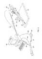
- FIG. 7is a diagram illustrating a top view of a remote controller according to an embodiment.
- FIG. 8is a component block diagram illustrating a remoter controller according to an embodiment.
- FIG. 9is a process flow diagram illustrating an embodiment method for outputting an indication of a corresponding catheter status at a remote controller of a catheter positioning system
- FIG. 10is a component block diagram illustrating a programmable control system computer suitable for use with the various embodiments.
- the systems, methods, and devices of the various embodimentsprovide a remote controller for a catheter positioning system configured to be operated with a single hand by a catheter positioning system operator.
- the remote controllermay include a thumb joystick control, first wheel control, and second wheel control.
- the remote controllermay include various visual indicators and/or haptic feedback mechanisms providing information to a catheter positioning system operator regarding an orientation and status of a catheter being positioned by a catheter positioning system.
- FIG. 1illustrates an example catheter 100 that may be used in various embodiments.
- the catheter 100may include a handle portion 102 and tube portion 116 and a tip portion 118 .
- the handle portion 102may be located at a proximal end of the catheter 100 while the distal end of the tube portion 116 may be inserted into the body of a patient.
- the handle portion 102 of the catheter 100may also include an irrigation port 110 , which may be used to introduce water or other fluids to lubricate the catheter and ease insertion or retraction into the patient.
- the handle portion 102may also include a back port 120 through which one or more wires or cables 112 may leave the handle portion 102 . Cables 112 may supply power to the catheter 100 or transmit signals, such as sending commands from a remote controller or other control device to the catheter or relaying data from one or more transducers present on the catheter.
- the handle portion 102may include actuators to control the behavior of the catheter 100 .
- the handle portion 102 shown in FIG. 1includes a front flange 104 a and rear flange 104 b that may be squeezed together such that the inner cylinder 108 slides inside the outer cylinder 106 . This motion may actuate one or more mechanism at the tip 118 of the catheter.
- the catheter 100may also be rotated about an axis 114 , such as by applying a rotational force on the flanges 104 a and 104 b or other components of the catheter 100 that will cause rotation of the tip 118 of the catheter. While the axis 114 illustrated in FIG. 1 is generally linear, it may conform to various curves of the tube portion 116 into which a catheter may be inserted.
- catheters described hereinare presented merely as examples of catheters which may be suitable for use with the various embodiments.
- any type of cathetermay be used.
- the various embodimentsmay be applicable to catheters with different actuators or functions, such as actuators for deflecting the tip of the catheter to ease navigation inside a patient and/or for controlling one or more transducers at the tip (e.g., electrical leads, one or more sensor devices, ultrasound devices, etc.).
- FIG. 2illustrates an embodiment catheter positioning device 200 with a remote controller 224 .
- the catheter positioning device 200may include a sled base 202 coupled with a sled member 204 .
- the sled base 202may be configured to advance the sled member 204 along the sled base 202 towards the body of the patient or back away from the patient.
- the sled membermay be moved with a motor 208 at one end of the sled base 202 .
- the sled member 204may move along a rail or other track, which may be configured with a driving mechanism such as a worm drive, back and forth along the longitudinal axis of the sled base 202 .
- the sled base 202may be mounted with an arm 212 , which may be configured with articulating joints and arms to position the sled base 202 over a surface, such as over an operating table 220 .
- the arm 212may be extended or rotated to position the sled base 202 relative to a patient on the operating table 220 .
- the sled base 202may include a handle 210 to move the sled base 202 into position.
- the sled basemay also include a nose cone 216 that may be inserted into a patient. Alternately, the nose cone 216 may connect with an introducer or sheath that may be inserted into the patient. A catheter may be advanced along the sled base 202 and through the nose cone 216 into the patient.
- the sled base 202may include a sterile barrier in the form of a re-sealable delivery channel 218 a to protect and guide the catheter along the sled base as it is advanced by the sled member 204 .
- the cathetermay be coupled to the catheter handle 102 and may be inserted into the delivery channel 218 a .
- the catheter handle 102may be connected to the sled member 204 (such as by using the modular plate 206 discussed below) such that the catheter is driven forward by translation of the sled member 204 along the re-sealable delivery channel 218 in the sled base 202 and through the nose cone 216 into the patient.
- the re-sealable delivery channel 218 amay be flexible to allow the catheter to be inserted and removed repeatedly.
- the re-sealable delivery channelmay have a resealing groove 218 b , such as with flexible plastic lips running along the top of the delivery channel 218 a along the longitudinal axis of the sled base 202 .
- the cathetermay be pushed through the resealing groove 218 b to position it inside the re-sealable delivery channel 218 a (i.e., the plastic lips may separate to let the catheter pass then come back together to seal behind the catheter).
- the cathetermay be removed by pulling the catheter back through the flexible plastic lips of the resealing groove 218 b .
- the re-sealable delivery channel 218 ais described herein as being re-sealable, in some embodiments the re-sealable deliver channel 218 a may be configured such that it is does not form a full seal, but merely closes enough to hold a catheter or a sheath within the channel to prevent buckling when the catheter is advanced towards/in the patient.
- the sled member 204may be coupled with a modular plate 206 to which a catheter handle 102 may be attached.
- Various embodiments of the modular plate 206may accommodate many alternate catheter and catheter handle and/or control mechanisms with a corresponding modular plate 206 that may be used so that the catheter positioning system can accommodate many different types of catheters.
- an appropriate modular plate 206may be attached to the sled member 204 and the catheter may be attached to the module plate 206 .
- the modular plate 206may also integrate with any actuators on the catheter handle 102 thereby allowing an operator to control the actuators via the remote controller 224 .
- the sled member 204may be configured to rotate the modular plate 206 , thereby rotating a catheter connected to the modular plate 206 .
- the sled member 204may be configured to drive a rotation of the modular plate 206 , or may be configured to rotate together with the modular plate 206 .
- the rotationmay be controlled remotely via the remote controller 224 .
- an operatormay position or use the catheter in any way necessary for a desired operation. Further, an operator may control each of these degrees of freedom (e.g., translation, rotation, actuation, etc.) remotely with the remote controller 224 .
- FIG. 3illustrates an exploded view of a catheter handle 102 , modular plate 206 , and sled member 204 .
- the catheter handle 102may include one or more actuators 302 .
- the catheter handle 102may further include a rotatable lever 303 as opposed to the flanges 104 a and 104 b shown in FIG. 1 to extend and retract the catheter.
- a different version of the modular plate 206may be used so that various catheters with different actuators may be connected to the catheter positioning device.
- FIG. 1illustrates an exploded view of a catheter handle 102 , modular plate 206 , and sled member 204 .
- the catheter handle 102may include one or more actuators 302 .
- the catheter handle 102may further include a rotatable lever 303 as opposed to the flanges 104 a and 104 b shown in FIG. 1 to extend and retract the catheter.
- a different version of the modular plate 206may be used so that various catheters with
- FIG 3illustrates a modular plate 206 that includes clamps 304 to secure the catheter handle 102 as well as a molded nest 306 configured to interface with the actuator 302 (i.e., the rotatable lever 303 may be controlled by rotating the molded nest 306 , which may interact with the actuators 302 ).
- the modular plate 206may be rigidly connected to the sled member 204 such that translation or rotation of the sled member is transferred through the modular plate 204 to the catheter handle 102 to drive and position the catheter in rotational or linearly translational movement.
- the sled member 204 and modular plate 206may be connected by one or more detachable joints having a connection mechanism, such as a socket 308 b that receives a tab 308 a of the modular plate 204 .
- the sled member 204may also include a control mechanism 310 to interface with the modular plate 206 .
- the control mechanism 310may allow the operator to control the catheter's actuators 302 , such as by controlling the molded nest 306 .
- the control mechanism 310 and the molded nestmay be configured with a universal adapter such that the control mechanism may interface with any of the various modular plates 206 designed to connect with different catheter handles.
- FIG. 4illustrates a view of a catheter handle 102 connected with the modular plate 206 and sled member 204 .
- FIG. 4illustrates a spreader 402 , which may facilitate the insertion of the catheter tube 116 into the resealing groove 218 b of the re-sealable delivery channel 218 a .
- the spreader 402may be attached to the modular plate 206 and configured to lead the catheter's tube portion 116 into the resealing groove 218 b of the re-sealable delivery channel 218 a .
- the end of the spreader 402may stay inside the resealing groove 218 b of the re-sealable delivery channel 218 a by moving between the plastic lips of the resealing groove 218 b .
- the lips of the resealing groove 218 bmay remain sealed over the re-sealable delivery channel 218 a and around the spreader 402 where it is inserted.
- the lips of the resealing groove 218 bmay open about the spreader 402 and reseal behind the spreader 402 providing a movable closure around the spreader 402 .
- FIG. 5illustrates an embodiment remote controller 224 from a side perspective view.
- the remote controller 224may be configured to enable a catheter positing system operator to control the operation of the catheter positing system with one hand using the remote controller 224 .
- the operatormay manipulate the remote controller 224 in a manner similar to the manner in which the operator would manipulate the catheter in a manual catheterization procedure, e.g. without the remote positioning system.
- surfaces, contours and control locations of the remote controller 224may be formed ergonomically.
- the remote controller 224may be formed, such as with a handle on a back side 514 of the body of the remote controller 224 .
- the shape of the back side 514may be configured to enable the remote controller 224 to be easily held in one hand.
- the remote controller 224may include various controls, such as a thumb joystick control 502 , a first wheel control 508 , and a second wheel control 512 disposed on various portions of the body of remoter controller 224 .
- additional aspects of the remote controller 224such as the size, the balance, the surface texture, the surface adhesion (e.g., stickiness), the grip contour, and so on, may be configured for a more positive control feel for the remote controller 224 .
- the thumb joystick control 502may extend from a surface 504 of the body of the remote controller 224 along a first axis.
- the thumb joystick control 502may extend from a top surface of the remote controller 224 in a manner configured to be similar to a top surface of a catheter handle.
- the thumb joystick control 502may be any type control, such as an analog or digital joystick, with four or more axis of control.
- forward deflection of the thumb joystick control 502 toward a front side 510 of the thumb joystick control 502may control the in or forward motion (e.g., extension) of a catheter, such as to slide the sled member 204 down the sled base 202 .
- a backward deflection of the thumb joystick control 502 toward a back side 514 of the remote controller 224may control the out or backward motion (e.g., retraction) of the catheter, such as to slide the sled member 204 up the sled base 202 .
- left deflection of the thumb joystick control 502 toward a left side 507 of the thumb joystick control 502may rotate the sled member 204 in a first direction
- right deflection of the thumb joystick control 502 toward a right side of the thumb joystick control 502may rotate the sled member 204 in a second direction, such as opposite the first direction.
- thumb joystick control 502may be used to control additional actuator elements on a catheter installed on the catheter positioning system. For example, pushing down on the thumb joystick control 502 may activate an irrigation function, a lighting function or other function.
- the thumb joystick control 502may be used as a momentary four-way switch. For example, deflections of the thumb joystick control 502 in the front, rear, left side and right side may each activate a separate momentary switch. Alternatively, the same momentary switch may be activated with different inputs and outputs depending on the direction of deflection.
- the momentary switchmay be a one shot switch that momentarily opens and closes for a fixed duration upon deflection. In other embodiments, the momentary switch may open (or close) for the duration of the deflection.
- the remote controller 224may include a selector switch 516 , such as a three position switch, which may be configured to send signals for selecting the features of the catheter positioning system that inputs to the thumb joystick control 502 may control.
- the selector switch 516may control whether deflection of the thumb joystick control 502 controls linear and rotary motions of the catheter only, sheath only, or both the catheter and sheath together, whether deflection of the thumb joystick control 502 activates a momentary switch or switches, and so on.
- the first wheel control 508may be located on the remote controller 224 below the thumb joystick control 502 . In an embodiment, the first wheel control 508 may be located near a bottom side 506 of the body of the remote controller 224 .
- the first wheel control 508may be a horizontal wheel rotating about a second axis, which may be a vertical axis with respect to a natural orientation of the remote controller (e.g., when held by an operator), such as an axis running from the bottom side 506 to the top side 504 of the remote controller 224 .
- the first wheel control 508may be housed within the body of the remote controller 224 and a first portion of the first wheel control 508 may extend out past a left side 507 and second portion may extend out past a right side of the remote controller 224 .
- the first wheel control 508may be any type control, such as an analog or digital control, for example a wheel coupled to a rotary encoder.
- rotation of the first wheel control 508may be used to generate signal sent to the catheter positioning system to steer a catheter having tip steering capability, such as turning the catheter tip left and/or right from a centered/straight orientation.
- rotation of the first wheel control 508may cause the remote controller 224 to send signals to the catheter positioning system to cause a rotation of a molded nest actuator interface on the modular plate 306 (e.g., FIG. 3 ) to rotate a catheter handle's actuator that will result in deflection of a distal tip of the catheter.
- the first axis of the thumb joystick control 502 and the second axis of the first wheel control 508may be coaxial (i.e., aligned with each other such that the first wheel control is below the thumb joystick control on the remote controller).
- the first axis of the thumb joystick control 502 and the second axis of the first wheel control 508may be parallel but offset from one another.
- the second wheel control 512may be located on a distal end of the remote controller 224 , such as the front end 510 of the body of the remote controller 224 .
- the second wheel control 512may be a vertical wheel rotating about a third axis, such as a horizontal axis running from the front side 510 of the remote controller 224 to the back side 514 of the remote controller 224 .
- the second wheel control 512may be any type of control, such as an analog or digital control, for example a wheel coupled to a rotary encoder.
- rotation of the second wheel control 512may cause the remote controller 224 to send signals to the catheter positioning system to cause movement of an actuator interface that turns an actuator on the catheter handle to adjust the diameter of a loop (or other shape change feature) on the distal tip of the catheter.
- rotating the second wheel control 512may cause the remote controller 224 to send signals to the catheter positioning system to cause it to move an actuator interface that turns an actuator on the catheter handle to adjust a loop diameter of a loop style diagnostic catheter.
- the functionality of the thumb joystick control 502 , the first wheel control 508 and the second wheel control 512may control the same catheter positioning actions.
- the first wheel control 508 and the second wheel control 512may provide the same level of control as the thumb joystick control 502 . In other implementations, the first wheel control 508 and the second wheel control 512 may provide a coarse adjustment of the control actions and the thumb joystick control 502 may provide finer adjustments of the control actions. Alternatively or additionally, the first wheel control 508 and the second wheel control 512 may allow control actions to be conducted when the thumb joystick control 502 is being used for other actions such as a four way switch, or momentary switch as described herein.
- the remote controller 224may include one or more optional indicators 520 , 522 , 524 which may visually indicate information.
- additional optional indicatorsmay be included on the remote controller 224 .
- additional lightsmay indicate whether the remote controller 224 is controlling the catheter, the sheath, or both the catheter and the sheath.
- the remote controller 224may illuminate to visually indicate information and the intensity and/or color of the illumination may be adjusted to indicate additional information.
- the remote controller 224may provide haptic feedback to a user.
- the remote controller 224may include a vibratory motor configured to cause the remote controller 224 to vibrate in the hand of a user to provide information to the user.
- the thumb joy stick control 502 , first wheel control 508 , and/or second wheel control 512may be configured to provide information to a user of the remote controller 224 by increasing and/or decreasing a resistance to motion of the thumb joy stick control 502 , first wheel control 508 , and/or second wheel control 512 by a user.
- one or more of the thumb joy stick control 502 , first wheel control 508 , and/or second wheel control 512may be configured with physical stops to prevent further movement of the thumb joy stick control 502 , first wheel control 508 , and/or second wheel control 512 when a limit of motion (e.g., a maximum rotation, a maximum deflection, a maximum extension, a maximum retraction, etc.) of the catheter and/or catheter positioning system is reached.
- a limit of motione.g., a maximum rotation, a maximum deflection, a maximum extension, a maximum retraction, etc.
- the remote controller 224may include a kill switch 525 used to determine whether the remote controller 224 is being held by a user.
- the kill switch 525may be an infrared switch that enables operation of the remote controller 224 by sensing heat from the hand of the operator when held.
- the kill switch 525may further cause the remote controller 224 to signal the remote catheter positioning system (e.g., a control computer coupled to the positioning system) when the remote controller 224 is being held by a user.
- the kill switch 525may disable the remoter controller 224 or signal the remote catheter positioning system when detecting that the remote controller 224 is not being held.
- Other examples of kill switches 525may include spring loaded buttons, light sensing switches, capacitive switches, etc.
- the remote controller 224may be configured to communicate control signals to a control computer or other devices of the catheter positioning system via a wired 606 , 606 ′ or wireless data link 607 , 607 ′ as illustrated in FIG. 6 .
- a remote controller 224may be connected to the by a wired connector 606 or a wireless data link 607 .
- the programmable control system 602may also be connected to the catheter positioning device 200 by a wired connector 604 or a wireless data link 605 .
- the remote controller 224may be configured to communicate control signals to a programmable control system 602 or other control devices of the catheter positioning system 200 via a wireless data link 607 , such as a Bluetooth® link, a Wi-Fi® link, an infrared data link, etc.
- a wireless data link 607such as a Bluetooth® link, a Wi-Fi® link, an infrared data link, etc. This embodiment may enable the clinician to manipulate the handle to better control the catheter positioning system 200 unimpeded by a control cable.
- the remote controller 224may be configured to communicate control signals to a control computer or other devices of the catheter positioning system via an optical fiber or electrical cable 606 .
- This embodimentmay reduce the chance of wireless control signals interfering with medical equipment (e.g., electrophysiology catheters).
- the remote controller 224may be configured to communicate control signals via a wireless data link 607 ′ (e.g., a Bluetooth® link, a Wi-Fi® link, an infrared data link, etc.) to a receiver device 608 , which may be positioned near the clinician behind shielding and configured to receive and relay those signals to a control computer or other devices of the catheter positioning system via an optical fiber or electrical cable 606 ′.
- a wireless data link 607 ′e.g., a Bluetooth® link, a Wi-Fi® link, an infrared data link, etc.
- a receiver device 608may be positioned near the clinician behind shielding and configured to receive and relay those signals to a control computer or other devices of the catheter positioning system via an optical fiber or electrical cable 606 ′.
- This embodimentmay combine the manipulation advantages of a wireless controller with reduced signal emissions within the operating room enabled by a wired or fiber optic control cable.
- wireless data links 605 , 607 and 607 ′may be established using any wireless communication protocol (e.g., Bluetooth®, Wi-Fi®, etc.).
- the wireless data linksmay be established using a secure communication protocol ensuring that only communications from authorized devices are accepted over the wireless data link.
- the programmable control system 602may output command signals to the catheter positioning system 200 based on or in response to signals received from the remote controller 224 . Additionally, the programmable control system 602 may be programmed based on signals received from the remote controller 224 to issue a sequence of command signals to the catheter positioning system 200 , such as through a calibration, training or programming operation. In such a calibration, training or programming operation, a clinician may manipulate the programmable control system 602 so as to cause the catheter positioning system 200 to advance, rotate and manipulate a catheter in a desired manner, and the control sequence may be stored in memory of the programmable control system 602 .
- Such system trainingmay be accomplished by recording command signals (e.g., signals received from the remote controller 224 or issued by the programmable control system 602 ) during an actual operation (essentially remembering the procedure), or in a dedicated training session in which the system is programmed without a patient present.
- command signalse.g., signals received from the remote controller 224 or issued by the programmable control system 602
- a usermay train the programmable control system to direct the positioning system to execute a series of translation and rotation movements by manipulating the control inputs on the remote controller 224 as if directing the movements in real time.
- Programmed movements of the positioning devicemay also be input or supplemented by entering commands into a keyboard.
- the programmable control system 602may store the command inputs and then combine the commands into a single programmed movement, such as in response to an operator selecting a number of pre-trained/programmed movements that should be accomplished in an indicated sequence.
- Programmed movementsmay include various combinations of the commands, such as simultaneously rotating and translating the system to create a “corkscrew” maneuver. These programmed movements may be triggered later by a single input, such as a user identifying the sequence by a file name or preset program and pressing an execute key on the controller or the system keyboard.
- the programmable control system 602may store different user profiles for different users of the remote controller 224 , such as in a storage device.
- the storage devicemay be a storage device associated with the programmable control system 602 , may be memory of the remote controller 224 , or a combination of storage locations.
- various user settings and/or preferences for the remote controller 224may be stored locally in a memory or storage device of the remote controller 224 and may be transferred to the programmable control system 602 to be stored in a memory or storage device, such as in association with a database of user settings.
- the user profilesmay include user selected levels for configurable settings of the remote controller 224 , such as sensitivities, friction, speed of rotation, speed of extension, speed of retraction, brightness of indicators, and resolution of various controls located on the remote controller, haptic feedback settings, etc.
- the programmable control system 602may identify the current user of the remote controller 224 , for example via a user log in, retrieve current the user's profile from a memory, and adjust the configurable settings to the selected levels indicated in the user profile. In this manner, configurable settings may be tailored to fit specific users of the remote controller 224 .
- FIG. 7illustrates three optional indicators or sets of indicators 520 , 522 , 524 that may be included in an embodiment of the remote controller 224 .
- each of the indicators 520 , 522 , 524may be a series of lights arranged in patterns, such as a pattern of individual light emitting diodes (LEDs).
- each of the indicators 520 , 522 , 524may be a display (e.g., an LED screen) configured to display images representing a series of lights arranged in patterns.
- the indicators 520 , 522 , 524may work together and/or separately to communicate information regarding the orientation of a catheter and/or the catheter positioning system 200 .
- a catheter tip orientation indicator 520may be provided on the remote controller 224 in the form of a series of lights A, B, C, D, E, F, G, H, I, J, K, and L arranged along two curves representative of different degrees of tip bend that can be introduced in steerable catheters.
- the indicator 520may also indicate a linear position, including a degree of insertion or retraction, such as through the illumination of lights E-H. By illuminating a correct one of the series of lights A, B, C, D, E, F, G, H, I, J, K, and L, the catheter tip orientation indicator 520 can inform a user of the catheter tip's current orientation/configuration.
- the illuminated light 702 corresponding to light B shown in FIG. 7may indicate that the tip of the catheter has been deflected (through articulation of the catheter control actuators by the catheter positioning system) to the left by three-fourths of its potential deflection.
- the catheter tip orientation indicator 520may inform the user whether the catheter tip is deflected, its direction, to the extent which it is deflected, including whether an articulation limit has been reached.
- a catheter rotation indicator 522may be provided on the remote controller 224 in the form of a series of lights a, b, c, d, e, f, g, h, i, j, k, l, m, n, o, and p arranged in a circle or ellipse, such as a ring around the thumb joystick control 502 .
- the catheter rotation indicator 522may indicate the angle of rotation of the catheter with respect to the handle up orientation. For example, in FIG. 7 the “n” catheter rotation indicator light 704 is illuminated indicating that the current rotational orientation of the catheter is about 67 degrees to the left. As another example, when the catheter is oriented with the handle facing up, the “a” light would be illuminated. This embodiment provides the clinician with an intuitive indication of rotational orientation, since the clinician can hold the controller vertical to see orientation as it would appear on the machine.
- the catheter positioning system 200can rotate the catheter in either direction and can rotate the catheter several times about its long axis, which can present a problem in terms of twisted connectors and fluid-carrying tubing. Therefore, an embodiment may also include a rotation count indicator 524 provided on the remote controller 224 in the form of a series of lights R, S, T, U, V, W, and X, such as arranged in an arc. This embodiment provides an intuitive indication of the direction (i.e., left, right, clockwise or counterclockwise, etc.) and the number of rotations through which the catheter has been rotated. The combination of the catheter rotation indicator 522 and the rotation count indicator 524 may provide the clinician with a complete picture of the rotational orientation of the catheter. For example, in FIG.
- the illumination of light S at 706may indicate the catheter has been rotated two full turns to the left and the illumination of light “n” at 704 may indicate that the catheter has been rotated an additional 67 degrees.
- the illuminated lights at 704 and 706indicates that the catheter has been rotated a total of about 787 decrees to the left.
- the lights “a” and Uwould be illuminated.
- the rotation count indicator 524may also indicate when catheter rotation limit has reached a limit, such as by illuminating lights R for maximum left rotations or light X for maximum right rotations.
- additional visible indicators 526 to indicate an operation mode or orientation of the catheter positioning systemmay be included on or within the remote controller 224 .
- Such indicators 526may be in the form of different colors, such as green, red, or yellow.
- the body of the remote controller 224may be of a translucent material and an indicator may be different colored lights within the handle that illuminate to turn the handle particular colors to indicate different conditions, operation modes or states of the catheter positioning system. For example, a green light 708 in the interior of the handle may illuminate to turn the handle green when a catheter has been properly inserted in the system is ready for operation, and a red light in the interior of the handle may illuminate to turn the handle red when it is not safe to operate the system.
- Other indicators and/or color combinationsmay be used to communicate control modes, such as catheter only control, sheath only control, or both catheter and sheath control.
- the illumination of visible indicators 526may indicate whether a catheter and/or catheter dock is positioned correctly or incorrectly in the catheter positioning system.
- FIG. 8is a component block diagram of the remote controller 224 illustrating various component parts according to one or more embodiments.
- the remote controller 224may include a thumb joystick control 502 coupled to a joystick digital encoder 503 connected to a processor 808 .
- the remote controller 224may include a first control wheel 508 coupled to a first rotational digital encoder 509 connected to the processor 808 , and a second control wheel 512 coupled to a second rotational digital encoder 513 connected to the processor 808 .
- the joystick digital encoder 503 , first rotational digital encoder 509 and second rotational digital encoder 513may generate signals indicating the position or movement their respective thumb joystick control 502 , the first control wheel 508 , and the second control wheel 512 (e.g., deflection angle, rotation, etc.), with such signals configured to interpretable by the processor 808 .
- the thumb joystick control 502 , the first control wheel 508 , and/or the second control wheel 512may include an actuator mechanism as part of or coupled to their respective digital encoder 509 , 513 and additional haptic actuator mechanisms 510 , 514 configured to provide haptic feedback, such as in the form of resistance to movement and/or vibration.
- the processor 808may configured to send haptic feedback control signals to the actuators within the thumb joystick control 502 , the first control wheel 508 , and/or the second control wheel 512 to generate perceptible haptic feedback a clinician handling the remote controller 224 , such as when a movement or actuation corresponding to the control input is nearing or has reached a limit.
- a catheter equipped with a tip pressure sensorsends signals indicating that the tip of the catheter is pressing against tissue (i.e., resisting further forward movement)
- signalsmay be interpreted by the programmable control system 602 , which may send control signals to the processor 808 of the remote controller 224 , which in turn may control a haptic actuator mechanism 510 , 514 to cause it to resist further actuation of its controller (e.g., the first control wheel 508 ).
- the haptic feedback resistance on the controller wheelmay simulate the tactile feel that the clinician would have when advancing the catheter manually.
- the force of the haptic feedback resistance generated by any of the haptic actuator mechanisms 510 , 514 in the remote controller 224may be adjustable.
- the programmable control system 602may identify the clinician operating the remote controller 224 and may send control signals to the processor 808 of the remote controller 224 indicating the level of haptic feedback resistance to generate for the clinician (for example, based on that clinician's user profile setting stored in a memory of the programmable control system 602 ).
- the processor 808may in turn control a haptic actuator mechanism 510 , 514 to cause it to resist further actuation of its controller with the level of haptic feedback resistance indicated in the received control signal. In this manner, the level of haptic feedback may be changed to fit a specific clinician and/or to increase or decrease a distraction factor caused by the haptic feedback.
- the catheter tip orientation indicator 520 , catheter rotation indicator 522 , and rotation count indicator 524 , and catheter status indicator 526may be connected to and controlled by the processor 808 to display visual indications to the user of the remote controller 224 as described above.
- the remote controller 224may include an internal illumination source 819 , such as one or more LEDs, connected to the processor 808 and configured to illuminate the body of the remote controller 224 in one or more colors.
- the body of the remote controller 224may be translucent or semi-transparent such that the illumination source 819 may cause the body of the remote controller to appear to glow when illuminated.
- a kill switch 525may be connected to the processor 808 and configured to sense when the remote controller 224 is being held by a user.
- the processor 808may be configured with processor executable instructions to determine a status of the kill switch 525 before performing operations to send control indications.
- the processor 808may be configured to send signals to the programmable control system 602 indicating when the remote controller 224 is being held by a user (or not) and the control system may be configured to limit or prevent remote operation of the catheter positioning system when such signals indicate the remote controller is not being held.
- the remote controller 224may include a vibratory motor 817 connected to the processor 808 and configured to vibrate the remote controller 224 in order to provide haptic feedback to a clinician holding the remote controller 224 .
- Such vibrating haptic feedbackmay be used to inform the clinician that a safety limit or threshold has been reached or an undesirable condition may result from further actuation.
- the remote controller 224may include a switch 516 connected to the processor 808 that is configured to control an operating mode of a catheter positioning system.
- the switch 516may be a multi-position switch to enable the clinician to select from a number of operating modes, such as a safe mode, automatic withdraw mode, an operate mode and a train mode.
- the remote controller 224may include a battery 814 connected to the processor 808 and/or other elements of the remote controller 808 requiring power to operate.
- the battery 814may be rechargeable, such as via an inductive charging circuit (not shown).
- FIG. 9illustrates an embodiment method 900 for outputting an indication of a corresponding catheter status at a remote controller of a catheter positioning system.
- the operations of method 900may be performed by a processor of a catheter positioning system (e.g., a processor within the programmable control system 602 described above with reference to FIG. 6 ) and a processor 808 of a remote controller.
- the catheter positioning system processormay determine a catheter positioning device status.
- the catheter positioning system processormay determine a rotation status (e.g., number of rotations of a sled member of a catheter positioning device), extension status (e.g., distance down a track of a positioning device), molded nest status (e.g., position of a rotatable molded nest), etc.
- the catheter positioning system processormay determine a corresponding catheter status.
- the catheter positioning system processormay reference a data table correlating catheter positioning device status information to catheter status information to determine a corresponding catheter status based on the determined catheter positioning device status.
- the catheter positioning system processormay use a data table of actuator characteristics to determine the actuator translation values for the particular catheter installed on the machine, and use the obtained actuator translation values to calculate a tip deflection of the catheter based on a measured angle or rotation (or number of rotations) of the catheter's tip-deflection actuator.
- the catheter positioning system processormay generate a control signal for activating a proper indication of the corresponding catheter status on a display or indicator on the remote controller.
- the catheter positioning system processormay generate a control signal for illuminating a proper light or lights of a display (e.g., one of displays 520 , 522 , 524 , 526 described above) on the remote controller to indicate the determined catheter status to a user of the remote controller.
- the catheter positioning system processormay generate a control signal for activating a haptic actuator or vibration motor to provide haptic feedback to the user that the catheter has reached maximum deflection, such as by resisting movement of a thumb joy stick and/or control wheel.
- the catheter positioning system processormay send the generated control signals to the remote controller and in block 910 the remote controller processor may receive the control signals.
- the remote controller processormay activate the corresponding display or haptic actuator/motor to output the proper indication of the corresponding catheter status.
- the remote controller processormay illuminate lights of a display 520 , 522 , 524 , or 526 on the remote controller to indicate the determined catheter status to a user of the remote controller.
- the remote controller processormay control a haptic actuator on the joy stick to stop/resist further movement of the thumb joy stick, thereby providing haptic feedback to the user that the catheter has reached a maximum deflection.
- the operations of method 900may be performed continually by the catheter positioning system processor and remote controller processor to output indications of the catheter status.
- a programmable control system computer 1010typically includes a processor 1011 coupled to volatile memory 1012 and a large capacity nonvolatile memory, such as a disk drive 1013 of Flash memory.
- the programmable control system computer 1010may also include a floppy disc drive 1014 and a compact disc (CD) drive 1015 coupled to the processor 1011 .
- CDcompact disc
- the programmable control system computer 1010may also include a number of connector ports coupled to the processor 1011 for establishing data connections to the remote controller and the catheter positioning system, and may be any form of connection such as a USB or FireWire® connector sockets. Ethernet sockets, or other network connection circuits for coupling the programmable control system computer 1010 to the catheter positioning system and/or a network.
- the programmable control system computer 1010 housingincludes the touchpad 1017 , the keyboard 1018 , and the display 1019 all coupled to the processor 1011 .
- Other configurations of the programmable control system computer 1010may include a computer mouse or trackball coupled to the processor (e.g., via a USB input) as are well known, which may also be use in conjunction with the various embodiments.
- the processors 808 and 1011may be any programmable microprocessor, microcomputer or multiple processor chip or chips that can be configured by software instructions (applications) to perform a variety of functions, including the functions of the various embodiments described above. In some devices, multiple processors may be provided, such as one processor dedicated to wireless communication functions and one processor dedicated to running other applications. Typically, software applications may be stored in the internal memory 812 , 1012 , 1013 before they are accessed and loaded into the processors 808 and 1011 .
- the processors 808 and 1011may include internal memory sufficient to store the application software instructions. In many devices the internal memory may be a volatile or nonvolatile memory, such as flash memory, or a mixture of both. For the purposes of this description, a general reference to memory refers to memory accessible by the processors 808 and 1011 including internal memory or removable memory plugged into the device and memory within the processor 808 and 1011 themselves.
- DSPdigital signal processor
- ASICapplication specific integrated circuit
- FPGAfield programmable gate array
- a general-purpose processormay be a microprocessor, but, in the alternative, the processor may be any conventional processor, controller, microcontroller, or state machine.
- a processormay also be implemented as a combination of computing devices, e.g., a combination of a DSP and a microprocessor, a plurality of microprocessors, one or more microprocessors in conjunction with a DSP core, or any other such configuration. Alternatively, some steps or methods may be performed by circuitry that is specific to a given function.
- the functions describedmay be implemented in hardware, software, firmware, or any combination thereof. If implemented in software, the functions may be stored as one or more instructions or code on a non-transitory computer-readable medium or non-transitory processor-readable medium. The steps of a method or algorithm disclosed herein may be embodied in a processor-executable software module which may reside on a non-transitory computer-readable or processor-readable storage medium. Non-transitory computer-readable or processor-readable storage media may be any storage media that may be accessed by a computer or a processor.
- non-transitory computer-readable or processor-readable mediamay include RAM, ROM, EEPROM, FLASH memory, CD-ROM or other optical disk storage, magnetic disk storage or other magnetic storage devices, or any other medium that may be used to store desired program code in the form of instructions or data structures and that may be accessed by a computer.
- Disk and discincludes compact disc (CD), laser disc, optical disc, digital versatile disc (DVD), floppy disk, and blu-ray disc where disks usually reproduce data magnetically, while discs reproduce data optically with lasers. Combinations of the above are also included within the scope of non-transitory computer-readable and processor-readable media.
- the operations of a method or algorithmmay reside as one or any combination or set of codes and/or instructions on a non-transitory processor-readable medium and/or computer-readable medium, which may be incorporated into a computer program product.
Landscapes
- Health & Medical Sciences (AREA)
- Life Sciences & Earth Sciences (AREA)
- Engineering & Computer Science (AREA)
- Surgery (AREA)
- Animal Behavior & Ethology (AREA)
- General Health & Medical Sciences (AREA)
- Biomedical Technology (AREA)
- Heart & Thoracic Surgery (AREA)
- Veterinary Medicine (AREA)
- Public Health (AREA)
- Molecular Biology (AREA)
- Nuclear Medicine, Radiotherapy & Molecular Imaging (AREA)
- Medical Informatics (AREA)
- Robotics (AREA)
- Biophysics (AREA)
- Physics & Mathematics (AREA)
- Pathology (AREA)
- Radiology & Medical Imaging (AREA)
- Pulmonology (AREA)
- Anesthesiology (AREA)
- Hematology (AREA)
- Media Introduction/Drainage Providing Device (AREA)
Abstract
Description
Claims (22)
Priority Applications (1)
| Application Number | Priority Date | Filing Date | Title |
|---|---|---|---|
| US14/478,738US9750577B2 (en) | 2013-09-06 | 2014-09-05 | Single hand operated remote controller for remote catheter positioning system |
Applications Claiming Priority (2)
| Application Number | Priority Date | Filing Date | Title |
|---|---|---|---|
| US201361874434P | 2013-09-06 | 2013-09-06 | |
| US14/478,738US9750577B2 (en) | 2013-09-06 | 2014-09-05 | Single hand operated remote controller for remote catheter positioning system |
Publications (2)
| Publication Number | Publication Date |
|---|---|
| US20150073340A1 US20150073340A1 (en) | 2015-03-12 |
| US9750577B2true US9750577B2 (en) | 2017-09-05 |
Family
ID=52626256
Family Applications (1)
| Application Number | Title | Priority Date | Filing Date |
|---|---|---|---|
| US14/478,738Active2035-09-12US9750577B2 (en) | 2013-09-06 | 2014-09-05 | Single hand operated remote controller for remote catheter positioning system |
Country Status (1)
| Country | Link |
|---|---|
| US (1) | US9750577B2 (en) |
Cited By (6)
| Publication number | Priority date | Publication date | Assignee | Title |
|---|---|---|---|---|
| US20210298795A1 (en)* | 2020-03-27 | 2021-09-30 | Mako Surgical Corp. | Robotic Spine Surgery System And Methods With Haptic Interface |
| US11147635B1 (en) | 2020-06-19 | 2021-10-19 | Remedy Robotics, Inc. | Systems and methods for guidance of intraluminal devices within the vasculature |
| US11690683B2 (en) | 2021-07-01 | 2023-07-04 | Remedy Robotics, Inc | Vision-based position and orientation determination for endovascular tools |
| US11707332B2 (en) | 2021-07-01 | 2023-07-25 | Remedy Robotics, Inc. | Image space control for endovascular tools |
| US11998287B1 (en) | 2019-03-18 | 2024-06-04 | Dopl Technologies Inc. | Platform for facilitating remote robotic medical procedures |
| US12121307B2 (en) | 2021-07-01 | 2024-10-22 | Remedy Robotics, Inc. | Vision-based position and orientation determination for endovascular tools |
Families Citing this family (31)
| Publication number | Priority date | Publication date | Assignee | Title |
|---|---|---|---|---|
| US8702773B2 (en) | 2008-12-17 | 2014-04-22 | The Spectranetics Corporation | Eccentric balloon laser catheter |
| EP3243476B1 (en)* | 2014-03-24 | 2019-11-06 | Auris Health, Inc. | Systems and devices for catheter driving instinctiveness |
| WO2016069754A1 (en) | 2014-10-29 | 2016-05-06 | The Spectranetics Corporation | Laser energy delivery devices including laser transmission detection systems and methods |
| US10492863B2 (en)* | 2014-10-29 | 2019-12-03 | The Spectranetics Corporation | Laser energy delivery devices including laser transmission detection systems and methods |
| US11351001B2 (en) | 2015-08-17 | 2022-06-07 | Intuitive Surgical Operations, Inc. | Ungrounded master control devices and methods of use |
| WO2017060439A1 (en)* | 2015-10-09 | 2017-04-13 | Koninklijke Philips N.V. | Advanced control features for steering devices for intravascular devices and associated systems and methods |
| JP7590072B2 (en)* | 2016-01-12 | 2024-11-26 | インテュイティブ サージカル オペレーションズ, インコーポレイテッド | Gradual force-feedback transitions between control states |
| US10675442B2 (en) | 2016-02-08 | 2020-06-09 | Nextern, Inc. | Robotically augmented catheter manipulation handle |
| US10874462B2 (en) | 2017-06-30 | 2020-12-29 | Biosense Webster (Israel) Ltd. | Network sniffer for system watchdog and diagnostic |
| WO2019023390A2 (en) | 2017-07-27 | 2019-01-31 | Intuitive Surgical Operations, Inc. | Medical device handle |
| US12419715B2 (en) | 2017-11-15 | 2025-09-23 | Intuitive Surgical Operations, Inc. | Master control device with multi-finger grip and methods therefor |
| WO2019099584A1 (en) | 2017-11-15 | 2019-05-23 | Intuitive Surgical Operations, Inc. | Master control device and methods therefor |
| US12329487B2 (en) | 2018-05-11 | 2025-06-17 | Intuitive Surgical Operations, Inc. | Master control device with finger grip sensing and methods therefor |
| WO2021079506A1 (en)* | 2019-10-25 | 2021-04-29 | オリンパス株式会社 | Insertion apparatus |
| US11013987B1 (en) | 2019-12-31 | 2021-05-25 | Dell Products L.P. | Information handling system controller scalable interface |
| US11260288B2 (en) | 2019-12-31 | 2022-03-01 | Dell Products L.P. | Disassemblable information handling system game controller |
| US11338197B2 (en) | 2019-12-31 | 2022-05-24 | Dell Products L.P. | Information handling system controller distributable hardware and logic management |
| US11331567B2 (en) | 2019-12-31 | 2022-05-17 | Dell Products L.P. | Information handling system and game controller trigger |
| US11097185B2 (en) | 2019-12-31 | 2021-08-24 | Dell Products L.P. | Detachable information handling system game controller management |
| US11097184B2 (en)* | 2019-12-31 | 2021-08-24 | Dell Products L.P. | Information handling system controller illumination |
| US11260291B2 (en) | 2019-12-31 | 2022-03-01 | Dell Products L.P. | Information handling system and detachable game controller |
| US11013991B1 (en) | 2019-12-31 | 2021-05-25 | Dell Products L.P. | Information handling system controller adaptive haptic feedback |
| US11501436B2 (en) | 2020-01-07 | 2022-11-15 | Cleerly, Inc. | Systems, methods, and devices for medical image analysis, diagnosis, risk stratification, decision making and/or disease tracking |
| US20220392065A1 (en) | 2020-01-07 | 2022-12-08 | Cleerly, Inc. | Systems, methods, and devices for medical image analysis, diagnosis, risk stratification, decision making and/or disease tracking |
| US11969280B2 (en) | 2020-01-07 | 2024-04-30 | Cleerly, Inc. | Systems, methods, and devices for medical image analysis, diagnosis, risk stratification, decision making and/or disease tracking |
| US11903766B2 (en)* | 2021-03-23 | 2024-02-20 | GE Precision Healthcare LLC | Systems and methods for a user interface for a medical imaging system |
| US12318161B2 (en) | 2021-10-05 | 2025-06-03 | Siemens Healthineers Endovascular Robotics, Inc. | Robotic actuation of elongated medical devices |
| US20250143657A1 (en) | 2022-03-10 | 2025-05-08 | Cleerly, Inc. | Systems, devices, and methods for non-invasive image-based plaque analysis and risk determination |
| US12406365B2 (en) | 2022-03-10 | 2025-09-02 | Cleerly, Inc. | Systems, devices, and methods for non-invasive image-based plaque analysis and risk determination |
| US20250217981A1 (en) | 2022-03-10 | 2025-07-03 | Cleerly, Inc. | Systems, methods, and devices for image-based plaque analysis and risk determination |
| CN120035410A (en)* | 2022-10-12 | 2025-05-23 | 直观外科手术操作公司 | Surgical system tactile feedback system |
Citations (90)
| Publication number | Priority date | Publication date | Assignee | Title |
|---|---|---|---|---|
| US4549538A (en) | 1982-11-12 | 1985-10-29 | Zimmer, Inc. | Pin inserter sheath |
| US4721123A (en) | 1986-10-23 | 1988-01-26 | Minntech Corporation | Catheter reprocessing system |
| US5226892A (en) | 1991-08-23 | 1993-07-13 | Boswell Thomas A | Surgical tubing clamp |
| US5644551A (en) | 1995-05-09 | 1997-07-01 | Carmichael; Edward | Adaptable engine usage meter |
| US5649956A (en) | 1995-06-07 | 1997-07-22 | Sri International | System and method for releasably holding a surgical instrument |
| US5682890A (en) | 1995-01-26 | 1997-11-04 | Picker International, Inc. | Magnetic resonance stereotactic surgery with exoskeleton tissue stabilization |
| US5814038A (en) | 1995-06-07 | 1998-09-29 | Sri International | Surgical manipulator for a telerobotic system |
| US5855583A (en) | 1996-02-20 | 1999-01-05 | Computer Motion, Inc. | Method and apparatus for performing minimally invasive cardiac procedures |
| US6063095A (en) | 1996-02-20 | 2000-05-16 | Computer Motion, Inc. | Method and apparatus for performing minimally invasive surgical procedures |
| US6096004A (en) | 1998-07-10 | 2000-08-01 | Mitsubishi Electric Information Technology Center America, Inc. (Ita) | Master/slave system for the manipulation of tubular medical tools |
| US6132368A (en) | 1996-12-12 | 2000-10-17 | Intuitive Surgical, Inc. | Multi-component telepresence system and method |
| US6171277B1 (en) | 1997-12-01 | 2001-01-09 | Cordis Webster, Inc. | Bi-directional control handle for steerable catheter |
| US6171234B1 (en) | 1998-09-25 | 2001-01-09 | Scimed Life Systems, Inc. | Imaging gore loading tool |
| US6200315B1 (en) | 1997-12-18 | 2001-03-13 | Medtronic, Inc. | Left atrium ablation catheter |
| US20010053879A1 (en) | 2000-04-07 | 2001-12-20 | Mills Gerald W. | Robotic trajectory guide |
| US20020042620A1 (en) | 1999-12-02 | 2002-04-11 | Intuitive Surgical, Inc. | In vivo accessories for minimally invasive robotic surgery |
| US6396232B2 (en) | 1997-11-03 | 2002-05-28 | Cybernet Haptic Systems Corporation | Haptic pointing devices |
| US6398755B1 (en) | 1998-10-06 | 2002-06-04 | Scimed Life Systems, Inc. | Driveable catheter system |
| US20020072704A1 (en) | 1998-08-05 | 2002-06-13 | Idriss Mansouri-Ruiz | Automatic/manual longitudinal position translator and rotary drive system for catheters |
| US20020120254A1 (en) | 1998-12-08 | 2002-08-29 | Intuitive Surgical, Inc. | Vivo accessories for minimally invasive robotic surgery |
| US6445984B1 (en) | 2001-05-25 | 2002-09-03 | The Raymond Corporation | Steer control system for material handling vehicles |
| US20020177789A1 (en) | 2001-05-06 | 2002-11-28 | Ferry Steven J. | System and methods for advancing a catheter |
| US6527782B2 (en) | 2000-06-07 | 2003-03-04 | Sterotaxis, Inc. | Guide for medical devices |
| US20030176778A1 (en)* | 2002-03-15 | 2003-09-18 | Scimed Life Systems, Inc. | Medical device control systems |
| US20040077942A1 (en) | 2002-03-11 | 2004-04-22 | Hall Andrew F. | 3D imaging for catheter interventions by use of positioning system |
| US6726675B1 (en) | 1998-03-11 | 2004-04-27 | Navicath Ltd. | Remote control catheterization |
| US6788999B2 (en) | 1992-01-21 | 2004-09-07 | Sri International, Inc. | Surgical system |
| US20040254566A1 (en) | 2003-01-31 | 2004-12-16 | Gianni Plicchi | Apparatus for the maneuvering of flexible catheters in the human cardiovascular system |
| US6850817B1 (en) | 1992-01-21 | 2005-02-01 | Sri International | Surgical system |
| US20050038412A1 (en) | 1999-09-24 | 2005-02-17 | Omnisonics Medical Technologies, Inc. | Apparatus and method for using a steerable catheter device |
| US20050065435A1 (en) | 2003-07-22 | 2005-03-24 | John Rauch | User interface for remote control of medical devices |
| US20050113719A1 (en) | 2003-09-26 | 2005-05-26 | Vahid Saadat | Left atrial access apparatus and methods |
| US20050203382A1 (en) | 2004-02-23 | 2005-09-15 | Assaf Govari | Robotically guided catheter |
| US20050209614A1 (en) | 2004-03-04 | 2005-09-22 | Fenter Felix W | Anastomosis apparatus and methods with computer-aided, automated features |
| WO2005087128A1 (en) | 2004-03-05 | 2005-09-22 | Hansen Medical, Inc. | Robotic catheter system |
| US20050228440A1 (en) | 1999-05-10 | 2005-10-13 | Endovia Medical Inc. | Surgical instrument |
| US20050277874A1 (en) | 2004-06-14 | 2005-12-15 | Selkee Thomas V | Steering mechanism for bi-directional catheter |
| US20060009735A1 (en) | 2004-06-29 | 2006-01-12 | Viswanathan Raju R | Navigation of remotely actuable medical device using control variable and length |
| US20060041181A1 (en) | 2004-06-04 | 2006-02-23 | Viswanathan Raju R | User interface for remote control of medical devices |
| US20060084945A1 (en) | 2004-03-05 | 2006-04-20 | Hansen Medical, Inc. | Instrument driver for robotic catheter system |
| US20060095022A1 (en) | 2004-03-05 | 2006-05-04 | Moll Frederic H | Methods using a robotic catheter system |
| US20060161138A1 (en) | 1996-12-12 | 2006-07-20 | Intuitive Surgical Inc. | Sterile surgical adaptor |
| US20060161137A1 (en) | 1997-11-21 | 2006-07-20 | Intuitive Surgical Inc. | Sterile surgical drape |
| US20060161136A1 (en) | 1997-11-21 | 2006-07-20 | Intuitive Surgical Inc. | Surgical accessory clamp and system method |
| US20060167441A1 (en) | 1996-02-20 | 2006-07-27 | Intuitive Surgical Inc. | Method and apparatus for performing minimally invasive cardiac procedures |
| US20060178559A1 (en) | 1998-11-20 | 2006-08-10 | Intuitive Surgical Inc. | Multi-user medical robotic system for collaboration or training in minimally invasive surgical procedures |
| US7090683B2 (en) | 1998-02-24 | 2006-08-15 | Hansen Medical, Inc. | Flexible instrument |
| US20060229587A1 (en) | 2004-06-03 | 2006-10-12 | Rafael Beyar | Transmission for a remote catheterization system |
| US20060235436A1 (en) | 1996-12-12 | 2006-10-19 | Intuitive Surgical Inc. | Sterile surgical adaptor |
| US20060270915A1 (en) | 2005-01-11 | 2006-11-30 | Ritter Rogers C | Navigation using sensed physiological data as feedback |
| US20070012135A1 (en) | 1996-12-12 | 2007-01-18 | Intuitive Surgical Inc. | Surgical robotic tools, data architecture, and use |
| US20070016174A1 (en) | 2005-06-30 | 2007-01-18 | Intuitive Surgical Inc. | Robotic surgical instruments with a fluid flow control system for irrigation, aspiration, and blowing |
| WO2007008967A2 (en) | 2005-07-11 | 2007-01-18 | Cardiac Inventions Unlimited, Inc. | Remotely controlled catheter insertion system |
| US20070019330A1 (en) | 2005-07-12 | 2007-01-25 | Charles Wolfersberger | Apparatus for pivotally orienting a projection device |
| US7169141B2 (en) | 1998-02-24 | 2007-01-30 | Hansen Medical, Inc. | Surgical instrument |
| US20070043455A1 (en) | 2005-07-26 | 2007-02-22 | Viswanathan Raju R | Apparatus and methods for automated sequential movement control for operation of a remote navigation system |
| US20070043338A1 (en) | 2004-03-05 | 2007-02-22 | Hansen Medical, Inc | Robotic catheter system and methods |
| US7214230B2 (en) | 1998-02-24 | 2007-05-08 | Hansen Medical, Inc. | Flexible instrument |
| US20070149946A1 (en) | 2005-12-07 | 2007-06-28 | Viswanathan Raju R | Advancer system for coaxial medical devices |
| US20070233044A1 (en) | 2006-02-22 | 2007-10-04 | Hansen Medical, Inc. | Apparatus for measuring distal forces on a working instrument |
| US20070239172A1 (en) | 2002-09-09 | 2007-10-11 | Hansen Medical, Inc. | Surgical instrument coupling mechanism |
| US20070283263A1 (en) | 2006-06-02 | 2007-12-06 | Synaptics, Inc. | Proximity sensor device and method with adjustment selection tabs |
| US20070299479A1 (en) | 2006-06-27 | 2007-12-27 | Ep Medsystems, Inc. | Method for Reversing Ventricular Dyssynchrony |
| US7314230B2 (en) | 2003-12-19 | 2008-01-01 | Takata Corporation | Kneebag and occupant leg protection system |
| US20080045892A1 (en) | 2001-05-06 | 2008-02-21 | Ferry Steven J | System and Methods for Advancing a Catheter |
| US20080059598A1 (en) | 2006-09-06 | 2008-03-06 | Garibaldi Jeffrey M | Coordinated Control for Multiple Computer-Controlled Medical Systems |
| US20080119872A1 (en) | 1998-02-24 | 2008-05-22 | Hansen Medical, Inc. | Surgical instrument |
| US20080119824A1 (en) | 2001-02-15 | 2008-05-22 | Hansen Medical, Inc. | Coaxial catheter system |
| US7377906B2 (en) | 2004-06-15 | 2008-05-27 | Biosense Webster, Inc. | Steering mechanism for bi-directional catheter |
| US20080125794A1 (en) | 1998-02-24 | 2008-05-29 | Hansen Medical, Inc. | Surgical instrument |
| US20080140087A1 (en) | 2006-05-17 | 2008-06-12 | Hansen Medical Inc. | Robotic instrument system |
| US20080183136A1 (en) | 2007-01-29 | 2008-07-31 | Onset Medical Corporation | Expandable intra-aortic balloon pump sheath |
| US20080245946A1 (en) | 2007-02-02 | 2008-10-09 | Hansen Medical, Inc. | Mounting support assembly for suspending a medical instrument driver above an operating table |
| US20080249536A1 (en) | 2007-02-15 | 2008-10-09 | Hansen Medical, Inc. | Interface assembly for controlling orientation of robotically controlled medical instrument |
| US20080300592A1 (en) | 2001-02-15 | 2008-12-04 | Hansen Medical, Inc. | Catheter driver system |
| US20090012533A1 (en) | 2007-04-23 | 2009-01-08 | Hansen Medical, Inc. | Robotic instrument control system |
| US20090082722A1 (en) | 2007-08-21 | 2009-03-26 | Munger Gareth T | Remote navigation advancer devices and methods of use |
| US20090105645A1 (en) | 2007-08-21 | 2009-04-23 | Brian Kidd | Apparatus for selectively rotating and/or advancing an elongate device |
| US7537570B2 (en) | 2006-09-11 | 2009-05-26 | Stereotaxis, Inc. | Automated mapping of anatomical features of heart chambers |
| WO2009092059A2 (en) | 2008-01-16 | 2009-07-23 | Catheter Robotics, Inc. | Remotely controlled catheter insertion system |
| US7630752B2 (en) | 2002-08-06 | 2009-12-08 | Stereotaxis, Inc. | Remote control of medical devices using a virtual device interface |
| US20100010475A1 (en) | 2008-07-08 | 2010-01-14 | Paul S. Teirstein | Guidewire and catheter management device |
| US7758564B2 (en) | 2004-05-14 | 2010-07-20 | Ethicon Endo-Surgery, Inc. | Medical instrument having a catheter and a medical guidewire |
| US20100256558A1 (en) | 2008-03-27 | 2010-10-07 | Olson Eric S | Robotic catheter system |
| US20110077590A1 (en) | 2009-09-30 | 2011-03-31 | Gianni Plicchi | Interface for Actuating a Robotic Manipulator from a Remote Position for Manoeuvring Steerable Catheters in the Human Cardiovascular System |
| US20120184955A1 (en) | 2008-01-16 | 2012-07-19 | Catheter Robotics Inc. | Remotely Controlled Catheter Insertion System with Automatic Control System |
| US20120182134A1 (en) | 2009-08-26 | 2012-07-19 | Carefusion 2200, Inc | Mechanisms for positioning and/or holding surgical instruments and performing other functions, and methods of manufacture and use thereof |
| US20130138118A1 (en) | 2010-01-26 | 2013-05-30 | Carefusion 2200, Inc. | Powered signal controlled hand actuated articulating device |
| US20130321262A1 (en)* | 2012-06-05 | 2013-12-05 | Stuart O. Schecter | Operating system with haptic interface for minimally invasive, hand-held surgical instrument |
| US20140371742A1 (en)* | 2013-06-18 | 2014-12-18 | Vascomed Gmbh | Anatomical Ablation System for the Purpose of Pulmonary Vein Isolation |
- 2014
- 2014-09-05USUS14/478,738patent/US9750577B2/enactiveActive
Patent Citations (130)
| Publication number | Priority date | Publication date | Assignee | Title |
|---|---|---|---|---|
| US4549538A (en) | 1982-11-12 | 1985-10-29 | Zimmer, Inc. | Pin inserter sheath |
| US4721123A (en) | 1986-10-23 | 1988-01-26 | Minntech Corporation | Catheter reprocessing system |
| US5226892A (en) | 1991-08-23 | 1993-07-13 | Boswell Thomas A | Surgical tubing clamp |
| US6788999B2 (en) | 1992-01-21 | 2004-09-07 | Sri International, Inc. | Surgical system |
| US7006895B2 (en) | 1992-01-21 | 2006-02-28 | Sri International | Computed pivotal center surgical robotic system and method |
| US6963792B1 (en) | 1992-01-21 | 2005-11-08 | Sri International | Surgical method |
| US20070276423A1 (en) | 1992-01-21 | 2007-11-29 | Sri International | Roll-Pitch-Roll Wrist Methods for Minimally Invasive Robotic Surgery |
| US6850817B1 (en) | 1992-01-21 | 2005-02-01 | Sri International | Surgical system |
| US6999852B2 (en) | 1992-01-21 | 2006-02-14 | Sri International | Flexible robotic surgery system and method |
| US5682890A (en) | 1995-01-26 | 1997-11-04 | Picker International, Inc. | Magnetic resonance stereotactic surgery with exoskeleton tissue stabilization |
| US5644551A (en) | 1995-05-09 | 1997-07-01 | Carmichael; Edward | Adaptable engine usage meter |
| US7204844B2 (en) | 1995-06-07 | 2007-04-17 | Sri, International | System and method for releasably holding a surgical instrument |
| US6080181A (en) | 1995-06-07 | 2000-06-27 | Sri International | System and method for releasably holding a surgical instrument |
| US5814038A (en) | 1995-06-07 | 1998-09-29 | Sri International | Surgical manipulator for a telerobotic system |
| US7648513B2 (en) | 1995-06-07 | 2010-01-19 | Sri International | Surgical manipulator for a telerobotic system |
| US6620174B2 (en) | 1995-06-07 | 2003-09-16 | Sri International | Surgical manipulator for a telerobotic system |
| US5810880A (en) | 1995-06-07 | 1998-09-22 | Sri International | System and method for releasably holding a surgical instrument |
| US6461372B1 (en) | 1995-06-07 | 2002-10-08 | Sri International | System and method for releasably holding a surgical instrument |
| US20050283140A1 (en) | 1995-06-07 | 2005-12-22 | Sri International | System and method for releasably holding a surgical instrument |
| US20070021776A1 (en) | 1995-06-07 | 2007-01-25 | Sri International | System and method for releasably holding a surgical instrument |
| US6413264B1 (en) | 1995-06-07 | 2002-07-02 | Sri International | Surgical manipulator for a telerobotic system |
| US5649956A (en) | 1995-06-07 | 1997-07-22 | Sri International | System and method for releasably holding a surgical instrument |
| US6063095A (en) | 1996-02-20 | 2000-05-16 | Computer Motion, Inc. | Method and apparatus for performing minimally invasive surgical procedures |
| US20080215065A1 (en) | 1996-02-20 | 2008-09-04 | Intuitive Surgical | Medical robotic arm that is attached to an operating table |
| US5855583A (en) | 1996-02-20 | 1999-01-05 | Computer Motion, Inc. | Method and apparatus for performing minimally invasive cardiac procedures |
| US6007550A (en) | 1996-02-20 | 1999-12-28 | Computer Motion, Inc. | Method and apparatus for performing minimally invasive cardiac procedures |
| US7118582B1 (en) | 1996-02-20 | 2006-10-10 | Computer Motion, Inc. | Method and apparatus for performing minimally invasive cardiac procedures |
| US20060167441A1 (en) | 1996-02-20 | 2006-07-27 | Intuitive Surgical Inc. | Method and apparatus for performing minimally invasive cardiac procedures |
| US20070012135A1 (en) | 1996-12-12 | 2007-01-18 | Intuitive Surgical Inc. | Surgical robotic tools, data architecture, and use |
| US6132368A (en) | 1996-12-12 | 2000-10-17 | Intuitive Surgical, Inc. | Multi-component telepresence system and method |
| US20060161138A1 (en) | 1996-12-12 | 2006-07-20 | Intuitive Surgical Inc. | Sterile surgical adaptor |
| US6346072B1 (en) | 1996-12-12 | 2002-02-12 | Intuitive Surgical, Inc. | Multi-component telepresence system and method |
| US20080147091A1 (en) | 1996-12-12 | 2008-06-19 | Intuitive Surgical, Inc. | Multi-component telepresence system and method |
| US7357774B2 (en) | 1996-12-12 | 2008-04-15 | Intuitive Surgical Inc. | Multi-component telepresence system and method |
| US20060235436A1 (en) | 1996-12-12 | 2006-10-19 | Intuitive Surgical Inc. | Sterile surgical adaptor |
| US6396232B2 (en) | 1997-11-03 | 2002-05-28 | Cybernet Haptic Systems Corporation | Haptic pointing devices |
| US20060161137A1 (en) | 1997-11-21 | 2006-07-20 | Intuitive Surgical Inc. | Sterile surgical drape |
| US20060161136A1 (en) | 1997-11-21 | 2006-07-20 | Intuitive Surgical Inc. | Surgical accessory clamp and system method |
| US6171277B1 (en) | 1997-12-01 | 2001-01-09 | Cordis Webster, Inc. | Bi-directional control handle for steerable catheter |
| US6200315B1 (en) | 1997-12-18 | 2001-03-13 | Medtronic, Inc. | Left atrium ablation catheter |
| US20070250073A1 (en) | 1998-02-24 | 2007-10-25 | Brock David L | Flexible instrument |
| US7169141B2 (en) | 1998-02-24 | 2007-01-30 | Hansen Medical, Inc. | Surgical instrument |
| US20080125793A1 (en) | 1998-02-24 | 2008-05-29 | Brock David L | Surgical instrument |
| US20080125794A1 (en) | 1998-02-24 | 2008-05-29 | Hansen Medical, Inc. | Surgical instrument |
| US7214230B2 (en) | 1998-02-24 | 2007-05-08 | Hansen Medical, Inc. | Flexible instrument |
| US20070260115A1 (en) | 1998-02-24 | 2007-11-08 | Brock David L | Flexible instrument |
| US7371210B2 (en) | 1998-02-24 | 2008-05-13 | Hansen Medical, Inc. | Flexible instrument |
| US7090683B2 (en) | 1998-02-24 | 2006-08-15 | Hansen Medical, Inc. | Flexible instrument |
| US20070250074A1 (en) | 1998-02-24 | 2007-10-25 | Brock David L | Flexible instrument |
| US20080119872A1 (en) | 1998-02-24 | 2008-05-22 | Hansen Medical, Inc. | Surgical instrument |
| US6726675B1 (en) | 1998-03-11 | 2004-04-27 | Navicath Ltd. | Remote control catheterization |
| US6096004A (en) | 1998-07-10 | 2000-08-01 | Mitsubishi Electric Information Technology Center America, Inc. (Ita) | Master/slave system for the manipulation of tubular medical tools |
| US20020072704A1 (en) | 1998-08-05 | 2002-06-13 | Idriss Mansouri-Ruiz | Automatic/manual longitudinal position translator and rotary drive system for catheters |
| US6171234B1 (en) | 1998-09-25 | 2001-01-09 | Scimed Life Systems, Inc. | Imaging gore loading tool |
| US6974465B2 (en) | 1998-10-06 | 2005-12-13 | Boston Scientific Scimed, Inc. | Driveable catheter system |
| US6398755B1 (en) | 1998-10-06 | 2002-06-04 | Scimed Life Systems, Inc. | Driveable catheter system |
| US20020183723A1 (en) | 1998-10-06 | 2002-12-05 | Scimed Life Systems, Inc. | Driveable catheter system |
| US20060084911A1 (en) | 1998-10-06 | 2006-04-20 | Boston Scientific Scimed, Inc. | Driveable catheter systems and methods |
| US20060178559A1 (en) | 1998-11-20 | 2006-08-10 | Intuitive Surgical Inc. | Multi-user medical robotic system for collaboration or training in minimally invasive surgical procedures |
| US20090248043A1 (en) | 1998-12-08 | 2009-10-01 | Intuitive Surgical, Inc. | Mechanical actuator interface system for robotic surgical tools |
| US20020120254A1 (en) | 1998-12-08 | 2002-08-29 | Intuitive Surgical, Inc. | Vivo accessories for minimally invasive robotic surgery |
| US20050228440A1 (en) | 1999-05-10 | 2005-10-13 | Endovia Medical Inc. | Surgical instrument |
| US20050038412A1 (en) | 1999-09-24 | 2005-02-17 | Omnisonics Medical Technologies, Inc. | Apparatus and method for using a steerable catheter device |
| US20020042620A1 (en) | 1999-12-02 | 2002-04-11 | Intuitive Surgical, Inc. | In vivo accessories for minimally invasive robotic surgery |
| US20080039869A1 (en) | 2000-04-07 | 2008-02-14 | Mills Gerald W | Robotic Trajectory Guide |
| US20010053879A1 (en) | 2000-04-07 | 2001-12-20 | Mills Gerald W. | Robotic trajectory guide |
| US6527782B2 (en) | 2000-06-07 | 2003-03-04 | Sterotaxis, Inc. | Guide for medical devices |
| US20090105639A1 (en) | 2001-02-15 | 2009-04-23 | Hansen Medical, Inc. | Catheter driver system |
| US20080300592A1 (en) | 2001-02-15 | 2008-12-04 | Hansen Medical, Inc. | Catheter driver system |
| US20080119824A1 (en) | 2001-02-15 | 2008-05-22 | Hansen Medical, Inc. | Coaxial catheter system |
| US20020177789A1 (en) | 2001-05-06 | 2002-11-28 | Ferry Steven J. | System and methods for advancing a catheter |
| US20080045892A1 (en) | 2001-05-06 | 2008-02-21 | Ferry Steven J | System and Methods for Advancing a Catheter |
| US7276044B2 (en) | 2001-05-06 | 2007-10-02 | Stereotaxis, Inc. | System and methods for advancing a catheter |
| US6445984B1 (en) | 2001-05-25 | 2002-09-03 | The Raymond Corporation | Steer control system for material handling vehicles |
| US20040077942A1 (en) | 2002-03-11 | 2004-04-22 | Hall Andrew F. | 3D imaging for catheter interventions by use of positioning system |
| US20030176778A1 (en)* | 2002-03-15 | 2003-09-18 | Scimed Life Systems, Inc. | Medical device control systems |
| US7630752B2 (en) | 2002-08-06 | 2009-12-08 | Stereotaxis, Inc. | Remote control of medical devices using a virtual device interface |
| US20070239172A1 (en) | 2002-09-09 | 2007-10-11 | Hansen Medical, Inc. | Surgical instrument coupling mechanism |
| US7331967B2 (en) | 2002-09-09 | 2008-02-19 | Hansen Medical, Inc. | Surgical instrument coupling mechanism |
| US20040254566A1 (en) | 2003-01-31 | 2004-12-16 | Gianni Plicchi | Apparatus for the maneuvering of flexible catheters in the human cardiovascular system |
| US20050065435A1 (en) | 2003-07-22 | 2005-03-24 | John Rauch | User interface for remote control of medical devices |
| US20050113719A1 (en) | 2003-09-26 | 2005-05-26 | Vahid Saadat | Left atrial access apparatus and methods |
| US7314230B2 (en) | 2003-12-19 | 2008-01-01 | Takata Corporation | Kneebag and occupant leg protection system |
| US8046049B2 (en) | 2004-02-23 | 2011-10-25 | Biosense Webster, Inc. | Robotically guided catheter |
| US20050203382A1 (en) | 2004-02-23 | 2005-09-15 | Assaf Govari | Robotically guided catheter |
| US20050209614A1 (en) | 2004-03-04 | 2005-09-22 | Fenter Felix W | Anastomosis apparatus and methods with computer-aided, automated features |
| WO2005087128A1 (en) | 2004-03-05 | 2005-09-22 | Hansen Medical, Inc. | Robotic catheter system |
| US20060084945A1 (en) | 2004-03-05 | 2006-04-20 | Hansen Medical, Inc. | Instrument driver for robotic catheter system |
| US20070043338A1 (en) | 2004-03-05 | 2007-02-22 | Hansen Medical, Inc | Robotic catheter system and methods |
| US20060293643A1 (en) | 2004-03-05 | 2006-12-28 | Wallace Daniel T | Robotic catheter system |
| US20050222554A1 (en) | 2004-03-05 | 2005-10-06 | Wallace Daniel T | Robotic catheter system |
| US20060095022A1 (en) | 2004-03-05 | 2006-05-04 | Moll Frederic H | Methods using a robotic catheter system |
| JP2007527296A (en) | 2004-03-05 | 2007-09-27 | ハンセン メディカル,インク. | Robotic guide catheter system |
| US7758564B2 (en) | 2004-05-14 | 2010-07-20 | Ethicon Endo-Surgery, Inc. | Medical instrument having a catheter and a medical guidewire |
| US20060229587A1 (en) | 2004-06-03 | 2006-10-12 | Rafael Beyar | Transmission for a remote catheterization system |
| US20060041181A1 (en) | 2004-06-04 | 2006-02-23 | Viswanathan Raju R | User interface for remote control of medical devices |
| US20050277874A1 (en) | 2004-06-14 | 2005-12-15 | Selkee Thomas V | Steering mechanism for bi-directional catheter |
| US7377906B2 (en) | 2004-06-15 | 2008-05-27 | Biosense Webster, Inc. | Steering mechanism for bi-directional catheter |
| US20060009735A1 (en) | 2004-06-29 | 2006-01-12 | Viswanathan Raju R | Navigation of remotely actuable medical device using control variable and length |
| US20060270915A1 (en) | 2005-01-11 | 2006-11-30 | Ritter Rogers C | Navigation using sensed physiological data as feedback |
| US20120197182A1 (en) | 2005-06-30 | 2012-08-02 | Intuitive Surgical, Inc. | Robotic Surgical Systems With Fluid Flow Control For Irrigation, Aspiration, and Blowing |
| US20070016174A1 (en) | 2005-06-30 | 2007-01-18 | Intuitive Surgical Inc. | Robotic surgical instruments with a fluid flow control system for irrigation, aspiration, and blowing |
| WO2007008967A2 (en) | 2005-07-11 | 2007-01-18 | Cardiac Inventions Unlimited, Inc. | Remotely controlled catheter insertion system |
| US8672880B2 (en) | 2005-07-11 | 2014-03-18 | Catheter Robotics Inc. | Remotely controlled catheter insertion system |
| US20120220931A1 (en) | 2005-07-11 | 2012-08-30 | Catheter Robotics Inc. | Remotely Controlled Catheter Insertion System |
| US20080009791A1 (en) | 2005-07-11 | 2008-01-10 | Cohen Todd J | Remotely controlled catheter insertion system |
| US20070019330A1 (en) | 2005-07-12 | 2007-01-25 | Charles Wolfersberger | Apparatus for pivotally orienting a projection device |
| US20070043455A1 (en) | 2005-07-26 | 2007-02-22 | Viswanathan Raju R | Apparatus and methods for automated sequential movement control for operation of a remote navigation system |
| US20070149946A1 (en) | 2005-12-07 | 2007-06-28 | Viswanathan Raju R | Advancer system for coaxial medical devices |
| US20070233044A1 (en) | 2006-02-22 | 2007-10-04 | Hansen Medical, Inc. | Apparatus for measuring distal forces on a working instrument |
| US20080140087A1 (en) | 2006-05-17 | 2008-06-12 | Hansen Medical Inc. | Robotic instrument system |
| US20070283263A1 (en) | 2006-06-02 | 2007-12-06 | Synaptics, Inc. | Proximity sensor device and method with adjustment selection tabs |
| US20070299479A1 (en) | 2006-06-27 | 2007-12-27 | Ep Medsystems, Inc. | Method for Reversing Ventricular Dyssynchrony |
| US20080059598A1 (en) | 2006-09-06 | 2008-03-06 | Garibaldi Jeffrey M | Coordinated Control for Multiple Computer-Controlled Medical Systems |
| US7537570B2 (en) | 2006-09-11 | 2009-05-26 | Stereotaxis, Inc. | Automated mapping of anatomical features of heart chambers |
| US20080183136A1 (en) | 2007-01-29 | 2008-07-31 | Onset Medical Corporation | Expandable intra-aortic balloon pump sheath |
| US20080245946A1 (en) | 2007-02-02 | 2008-10-09 | Hansen Medical, Inc. | Mounting support assembly for suspending a medical instrument driver above an operating table |
| US20080249536A1 (en) | 2007-02-15 | 2008-10-09 | Hansen Medical, Inc. | Interface assembly for controlling orientation of robotically controlled medical instrument |
| US20090012533A1 (en) | 2007-04-23 | 2009-01-08 | Hansen Medical, Inc. | Robotic instrument control system |
| US20090082722A1 (en) | 2007-08-21 | 2009-03-26 | Munger Gareth T | Remote navigation advancer devices and methods of use |
| US20090105645A1 (en) | 2007-08-21 | 2009-04-23 | Brian Kidd | Apparatus for selectively rotating and/or advancing an elongate device |
| US20120184955A1 (en) | 2008-01-16 | 2012-07-19 | Catheter Robotics Inc. | Remotely Controlled Catheter Insertion System with Automatic Control System |
| WO2009092059A2 (en) | 2008-01-16 | 2009-07-23 | Catheter Robotics, Inc. | Remotely controlled catheter insertion system |
| US20100256558A1 (en) | 2008-03-27 | 2010-10-07 | Olson Eric S | Robotic catheter system |
| US20100010475A1 (en) | 2008-07-08 | 2010-01-14 | Paul S. Teirstein | Guidewire and catheter management device |
| US20120182134A1 (en) | 2009-08-26 | 2012-07-19 | Carefusion 2200, Inc | Mechanisms for positioning and/or holding surgical instruments and performing other functions, and methods of manufacture and use thereof |
| US20110077590A1 (en) | 2009-09-30 | 2011-03-31 | Gianni Plicchi | Interface for Actuating a Robotic Manipulator from a Remote Position for Manoeuvring Steerable Catheters in the Human Cardiovascular System |
| US20130138118A1 (en) | 2010-01-26 | 2013-05-30 | Carefusion 2200, Inc. | Powered signal controlled hand actuated articulating device |
| US20130321262A1 (en)* | 2012-06-05 | 2013-12-05 | Stuart O. Schecter | Operating system with haptic interface for minimally invasive, hand-held surgical instrument |
| US20140371742A1 (en)* | 2013-06-18 | 2014-12-18 | Vascomed Gmbh | Anatomical Ablation System for the Purpose of Pulmonary Vein Isolation |
Non-Patent Citations (18)
| Title |
|---|
| Canadian Application 2,646,846, Office Action dated Sep. 19, 2012. |
| Chinese Application 200680025512.7, State Intellectual Property Office of the People's Republic of China, Office Action dated Feb. 13, 2012. |
| Chinese Application 200980102420.8, State Intellectual Property Office of the People's Republic of China, Office Action dated Feb. 16, 2012. |
| Extended European Search Report of Apr. 17, 2013; European Application No. 09702983.9. |
| Hein et al., "Robot Supported Insertion of Catheters for Hyperthermia and Branch Therapy," Computer Assisted Radiology and Surgery, 1998, pp. 660-663. |
| International Preliminary Report on Patentability, Intl Application PCT/US2009/031357. International Bureau of WIPO, Jul. 29, 2010. |
| International Search Report and Written Opinion, Intl Application PCT/US2009/031357. International Search Authority, U.S. Patent and Trademark Office (ISA/US), Mar. 19, 2009. |
| Japanese Patent Application No. 2010-543298; Office Action of Mar. 19, 2013. |
| Macoviak, "Catheter System for Surgical Access and Circulatory Support of the Heart," USPTO, Official Gazette, vol. 1278, Jan. 6, 2004. |
| State Intellectual Property Office of the People's Republic of China, First Office Action, Oct. 30, 2009, Chinese Patent Application 200680025512.7, "Remotely Controlled Catheter Insertion System," with English translation, (24 pgs. total). |
| U.S. Appl. No. 12/515,005, Non-Final Office Action dated Apr. 11, 2013. |
| U.S. Appl. No. 12/903,397, Non-Final Office Action dated Nov. 19, 2012. |
| U.S. Appl. No. 13/051,736, Final Office Action dated Nov. 5, 2012. |
| U.S. Appl. No. 13/051,736, Non-Final Office Action dated Jul. 17, 2012. |
| U.S. Appl. No. 13/078,663, Non-Final Office Action dated Aug. 14, 2014. |
| U.S. Appl. No. 13/461,463, Final Office Action dated Jun. 27, 2014. |
| U.S. Appl. No. 13/461,463, Non-Final Office Action dated Oct. 31, 2014. |
| WIPO, International Preliminary Report on Patentability; PCT/US2006/027024; Jan. 16, 2008; 8pgs. |
Cited By (12)
| Publication number | Priority date | Publication date | Assignee | Title |
|---|---|---|---|---|
| US11998287B1 (en) | 2019-03-18 | 2024-06-04 | Dopl Technologies Inc. | Platform for facilitating remote robotic medical procedures |
| US20210298795A1 (en)* | 2020-03-27 | 2021-09-30 | Mako Surgical Corp. | Robotic Spine Surgery System And Methods With Haptic Interface |
| US11147635B1 (en) | 2020-06-19 | 2021-10-19 | Remedy Robotics, Inc. | Systems and methods for guidance of intraluminal devices within the vasculature |
| US11154366B1 (en) | 2020-06-19 | 2021-10-26 | Remedy Robotics, Inc. | Systems and methods for guidance of intraluminal devices within the vasculature |
| US11197725B1 (en) | 2020-06-19 | 2021-12-14 | Remedy Robotics, Inc. | Systems and methods for guidance of intraluminal devices within the vasculature |
| US11229488B2 (en) | 2020-06-19 | 2022-01-25 | Remedy Robotics, Inc. | Systems and methods for guidance of intraluminal devices within the vasculature |
| US11246667B2 (en) | 2020-06-19 | 2022-02-15 | Remedy Robotics, Inc. | Systems and methods for guidance of intraluminal devices within the vasculature |
| US11779406B2 (en) | 2020-06-19 | 2023-10-10 | Remedy Robotics, Inc. | Systems and methods for guidance of intraluminal devices within the vasculature |
| US12193764B2 (en) | 2020-06-19 | 2025-01-14 | Remedy Robotics, Inc. | Systems and methods for guidance of intraluminal devices within the vasculature |
| US11690683B2 (en) | 2021-07-01 | 2023-07-04 | Remedy Robotics, Inc | Vision-based position and orientation determination for endovascular tools |
| US11707332B2 (en) | 2021-07-01 | 2023-07-25 | Remedy Robotics, Inc. | Image space control for endovascular tools |
| US12121307B2 (en) | 2021-07-01 | 2024-10-22 | Remedy Robotics, Inc. | Vision-based position and orientation determination for endovascular tools |
Also Published As
| Publication number | Publication date |
|---|---|
| US20150073340A1 (en) | 2015-03-12 |
Similar Documents
| Publication | Publication Date | Title |
|---|---|---|
| US9750577B2 (en) | Single hand operated remote controller for remote catheter positioning system | |
| US11918763B2 (en) | Robotically augmented catheter manipulation handle | |
| US12364543B2 (en) | Patient introducer alignment | |
| US8641663B2 (en) | Robotic catheter system input device | |
| US11191596B2 (en) | Foot controller | |
| JP7099728B2 (en) | User controller with user presence detection, related systems and methods | |
| AU2017203633C1 (en) | Robotic systems, robotic system user interfaces, human interface devices for controlling robotic systems and methods of controlling robotic systems | |
| KR102372151B1 (en) | Medical holding arm with annular LED display means | |
| JP5773884B2 (en) | Robot catheter system input device | |
| US8986246B2 (en) | Remotely controlled catheter insertion system | |
| US9993614B2 (en) | Components for multiple axis control of a catheter in a catheter positioning system | |
| DE102015104819B4 (en) | Holding arm for medical purposes with removable operating device, and operating device therefor | |
| CN107744405A (en) | A kind of robot is from end device, operating system and its control method | |
| KR101967635B1 (en) | End effector and remote control apparatus | |
| CN108289691A (en) | Plug-type stitching unstrument with two degrees of freedom wrist | |
| JP2019504655A (en) | Handheld steering device for intravascular devices and related systems and methods | |
| KR20150092721A (en) | Mobile medical device and method for controlling a movement of the mobile medical device | |
| BR112015020589B1 (en) | ROBOTIC MANIPULATOR SYSTEM | |
| US10772701B2 (en) | Method and apparatus to project light pattern to determine distance in a surgical scene | |
| CN107744616A (en) | A kind of catheter controller and its application method | |
| US8206157B2 (en) | Instrument for use in a medical simulator | |
| US20230372034A1 (en) | Trajectory tracking for medical device | |
| CN114430847B (en) | Multi-tool medical simulation system and method | |
| WO2025085438A1 (en) | Systems and methods for actuating an instrument system | |
| WO2023089473A1 (en) | Determining information about a surgical port in a surgical robotic system |
Legal Events
| Date | Code | Title | Description |
|---|---|---|---|
| AS | Assignment | Owner name:CATHETER ROBOTICS INC., NEW JERSEY Free format text:ASSIGNMENT OF ASSIGNORS INTEREST;ASSIGNORS:PACHECO, ROBERT;FOLEY, STEVE;JENKINS, DAVID;AND OTHERS;SIGNING DATES FROM 20150810 TO 20151007;REEL/FRAME:036831/0420 | |
| AS | Assignment | Owner name:CATHETER PRECISION, INC., NEW JERSEY Free format text:CHANGE OF NAME;ASSIGNOR:CATHETER ROBOTICS INC.;REEL/FRAME:039633/0719 Effective date:20160519 | |
| AS | Assignment | Owner name:CATHETER PRECISION, INC., NEW JERSEY Free format text:CHANGE OF NAME;ASSIGNOR:CATHETER ROBOTICS INC.;REEL/FRAME:040581/0409 Effective date:20160519 | |
| STCF | Information on status: patent grant | Free format text:PATENTED CASE | |
| FEPP | Fee payment procedure | Free format text:SURCHARGE FOR LATE PAYMENT, SMALL ENTITY (ORIGINAL EVENT CODE: M2554); ENTITY STATUS OF PATENT OWNER: SMALL ENTITY | |
| MAFP | Maintenance fee payment | Free format text:PAYMENT OF MAINTENANCE FEE, 4TH YR, SMALL ENTITY (ORIGINAL EVENT CODE: M2551); ENTITY STATUS OF PATENT OWNER: SMALL ENTITY Year of fee payment:4 | |
| MAFP | Maintenance fee payment | Free format text:PAYMENT OF MAINTENANCE FEE, 8TH YR, SMALL ENTITY (ORIGINAL EVENT CODE: M2552); ENTITY STATUS OF PATENT OWNER: SMALL ENTITY Year of fee payment:8 |