US9750563B2 - Systems and methods for treating tissue with radiofrequency energy - Google Patents
Systems and methods for treating tissue with radiofrequency energyDownload PDFInfo
- Publication number
- US9750563B2 US9750563B2US14/708,210US201514708210AUS9750563B2US 9750563 B2US9750563 B2US 9750563B2US 201514708210 AUS201514708210 AUS 201514708210AUS 9750563 B2US9750563 B2US 9750563B2
- Authority
- US
- United States
- Prior art keywords
- electrodes
- tissue
- arms
- basket
- tube
- Prior art date
- Legal status (The legal status is an assumption and is not a legal conclusion. Google has not performed a legal analysis and makes no representation as to the accuracy of the status listed.)
- Expired - Fee Related
Links
Images


Classifications
- A—HUMAN NECESSITIES
- A61—MEDICAL OR VETERINARY SCIENCE; HYGIENE
- A61B—DIAGNOSIS; SURGERY; IDENTIFICATION
- A61B18/00—Surgical instruments, devices or methods for transferring non-mechanical forms of energy to or from the body
- A61B18/04—Surgical instruments, devices or methods for transferring non-mechanical forms of energy to or from the body by heating
- A61B18/12—Surgical instruments, devices or methods for transferring non-mechanical forms of energy to or from the body by heating by passing a current through the tissue to be heated, e.g. high-frequency current
- A61B18/14—Probes or electrodes therefor
- A61B18/1485—Probes or electrodes therefor having a short rigid shaft for accessing the inner body through natural openings
- A—HUMAN NECESSITIES
- A61—MEDICAL OR VETERINARY SCIENCE; HYGIENE
- A61B—DIAGNOSIS; SURGERY; IDENTIFICATION
- A61B18/00—Surgical instruments, devices or methods for transferring non-mechanical forms of energy to or from the body
- A61B18/04—Surgical instruments, devices or methods for transferring non-mechanical forms of energy to or from the body by heating
- A61B18/12—Surgical instruments, devices or methods for transferring non-mechanical forms of energy to or from the body by heating by passing a current through the tissue to be heated, e.g. high-frequency current
- A61B18/1206—Generators therefor
- A—HUMAN NECESSITIES
- A61—MEDICAL OR VETERINARY SCIENCE; HYGIENE
- A61B—DIAGNOSIS; SURGERY; IDENTIFICATION
- A61B34/00—Computer-aided surgery; Manipulators or robots specially adapted for use in surgery
- A61B34/25—User interfaces for surgical systems
- G—PHYSICS
- G06—COMPUTING OR CALCULATING; COUNTING
- G06F—ELECTRIC DIGITAL DATA PROCESSING
- G06F3/00—Input arrangements for transferring data to be processed into a form capable of being handled by the computer; Output arrangements for transferring data from processing unit to output unit, e.g. interface arrangements
- G06F3/01—Input arrangements or combined input and output arrangements for interaction between user and computer
- G06F3/048—Interaction techniques based on graphical user interfaces [GUI]
- G06F3/0481—Interaction techniques based on graphical user interfaces [GUI] based on specific properties of the displayed interaction object or a metaphor-based environment, e.g. interaction with desktop elements like windows or icons, or assisted by a cursor's changing behaviour or appearance
- A—HUMAN NECESSITIES
- A61—MEDICAL OR VETERINARY SCIENCE; HYGIENE
- A61B—DIAGNOSIS; SURGERY; IDENTIFICATION
- A61B18/00—Surgical instruments, devices or methods for transferring non-mechanical forms of energy to or from the body
- A61B18/02—Surgical instruments, devices or methods for transferring non-mechanical forms of energy to or from the body by cooling, e.g. cryogenic techniques
- A—HUMAN NECESSITIES
- A61—MEDICAL OR VETERINARY SCIENCE; HYGIENE
- A61B—DIAGNOSIS; SURGERY; IDENTIFICATION
- A61B18/00—Surgical instruments, devices or methods for transferring non-mechanical forms of energy to or from the body
- A61B18/04—Surgical instruments, devices or methods for transferring non-mechanical forms of energy to or from the body by heating
- A61B18/08—Surgical instruments, devices or methods for transferring non-mechanical forms of energy to or from the body by heating by means of electrically-heated probes
- A—HUMAN NECESSITIES
- A61—MEDICAL OR VETERINARY SCIENCE; HYGIENE
- A61B—DIAGNOSIS; SURGERY; IDENTIFICATION
- A61B18/00—Surgical instruments, devices or methods for transferring non-mechanical forms of energy to or from the body
- A61B18/04—Surgical instruments, devices or methods for transferring non-mechanical forms of energy to or from the body by heating
- A61B18/12—Surgical instruments, devices or methods for transferring non-mechanical forms of energy to or from the body by heating by passing a current through the tissue to be heated, e.g. high-frequency current
- A61B18/14—Probes or electrodes therefor
- A61B18/1477—Needle-like probes
- A—HUMAN NECESSITIES
- A61—MEDICAL OR VETERINARY SCIENCE; HYGIENE
- A61B—DIAGNOSIS; SURGERY; IDENTIFICATION
- A61B18/00—Surgical instruments, devices or methods for transferring non-mechanical forms of energy to or from the body
- A61B18/04—Surgical instruments, devices or methods for transferring non-mechanical forms of energy to or from the body by heating
- A61B18/12—Surgical instruments, devices or methods for transferring non-mechanical forms of energy to or from the body by heating by passing a current through the tissue to be heated, e.g. high-frequency current
- A61B18/14—Probes or electrodes therefor
- A61B18/1492—Probes or electrodes therefor having a flexible, catheter-like structure, e.g. for heart ablation
- A—HUMAN NECESSITIES
- A61—MEDICAL OR VETERINARY SCIENCE; HYGIENE
- A61B—DIAGNOSIS; SURGERY; IDENTIFICATION
- A61B18/00—Surgical instruments, devices or methods for transferring non-mechanical forms of energy to or from the body
- A61B18/18—Surgical instruments, devices or methods for transferring non-mechanical forms of energy to or from the body by applying electromagnetic radiation, e.g. microwaves
- A61B18/1815—Surgical instruments, devices or methods for transferring non-mechanical forms of energy to or from the body by applying electromagnetic radiation, e.g. microwaves using microwaves
- A—HUMAN NECESSITIES
- A61—MEDICAL OR VETERINARY SCIENCE; HYGIENE
- A61B—DIAGNOSIS; SURGERY; IDENTIFICATION
- A61B18/00—Surgical instruments, devices or methods for transferring non-mechanical forms of energy to or from the body
- A61B2018/00005—Cooling or heating of the probe or tissue immediately surrounding the probe
- A61B2018/00011—Cooling or heating of the probe or tissue immediately surrounding the probe with fluids
- A61B2018/00029—Cooling or heating of the probe or tissue immediately surrounding the probe with fluids open
- A—HUMAN NECESSITIES
- A61—MEDICAL OR VETERINARY SCIENCE; HYGIENE
- A61B—DIAGNOSIS; SURGERY; IDENTIFICATION
- A61B18/00—Surgical instruments, devices or methods for transferring non-mechanical forms of energy to or from the body
- A61B2018/00053—Mechanical features of the instrument of device
- A61B2018/00214—Expandable means emitting energy, e.g. by elements carried thereon
- A61B2018/0022—Balloons
- A—HUMAN NECESSITIES
- A61—MEDICAL OR VETERINARY SCIENCE; HYGIENE
- A61B—DIAGNOSIS; SURGERY; IDENTIFICATION
- A61B18/00—Surgical instruments, devices or methods for transferring non-mechanical forms of energy to or from the body
- A61B2018/00053—Mechanical features of the instrument of device
- A61B2018/00214—Expandable means emitting energy, e.g. by elements carried thereon
- A61B2018/00267—Expandable means emitting energy, e.g. by elements carried thereon having a basket shaped structure
- A—HUMAN NECESSITIES
- A61—MEDICAL OR VETERINARY SCIENCE; HYGIENE
- A61B—DIAGNOSIS; SURGERY; IDENTIFICATION
- A61B18/00—Surgical instruments, devices or methods for transferring non-mechanical forms of energy to or from the body
- A61B2018/00315—Surgical instruments, devices or methods for transferring non-mechanical forms of energy to or from the body for treatment of particular body parts
- A61B2018/00482—Digestive system
- A61B2018/00488—Esophagus
- A—HUMAN NECESSITIES
- A61—MEDICAL OR VETERINARY SCIENCE; HYGIENE
- A61B—DIAGNOSIS; SURGERY; IDENTIFICATION
- A61B18/00—Surgical instruments, devices or methods for transferring non-mechanical forms of energy to or from the body
- A61B2018/00315—Surgical instruments, devices or methods for transferring non-mechanical forms of energy to or from the body for treatment of particular body parts
- A61B2018/00482—Digestive system
- A61B2018/00494—Stomach, intestines or bowel
- A—HUMAN NECESSITIES
- A61—MEDICAL OR VETERINARY SCIENCE; HYGIENE
- A61B—DIAGNOSIS; SURGERY; IDENTIFICATION
- A61B18/00—Surgical instruments, devices or methods for transferring non-mechanical forms of energy to or from the body
- A61B2018/00315—Surgical instruments, devices or methods for transferring non-mechanical forms of energy to or from the body for treatment of particular body parts
- A61B2018/00482—Digestive system
- A61B2018/005—Rectum
- A—HUMAN NECESSITIES
- A61—MEDICAL OR VETERINARY SCIENCE; HYGIENE
- A61B—DIAGNOSIS; SURGERY; IDENTIFICATION
- A61B18/00—Surgical instruments, devices or methods for transferring non-mechanical forms of energy to or from the body
- A61B2018/00315—Surgical instruments, devices or methods for transferring non-mechanical forms of energy to or from the body for treatment of particular body parts
- A61B2018/00553—Sphincter
- A—HUMAN NECESSITIES
- A61—MEDICAL OR VETERINARY SCIENCE; HYGIENE
- A61B—DIAGNOSIS; SURGERY; IDENTIFICATION
- A61B18/00—Surgical instruments, devices or methods for transferring non-mechanical forms of energy to or from the body
- A61B2018/00571—Surgical instruments, devices or methods for transferring non-mechanical forms of energy to or from the body for achieving a particular surgical effect
- A61B2018/00577—Ablation
- A—HUMAN NECESSITIES
- A61—MEDICAL OR VETERINARY SCIENCE; HYGIENE
- A61B—DIAGNOSIS; SURGERY; IDENTIFICATION
- A61B18/00—Surgical instruments, devices or methods for transferring non-mechanical forms of energy to or from the body
- A61B2018/00636—Sensing and controlling the application of energy
- A61B2018/00642—Sensing and controlling the application of energy with feedback, i.e. closed loop control
- A—HUMAN NECESSITIES
- A61—MEDICAL OR VETERINARY SCIENCE; HYGIENE
- A61B—DIAGNOSIS; SURGERY; IDENTIFICATION
- A61B18/00—Surgical instruments, devices or methods for transferring non-mechanical forms of energy to or from the body
- A61B2018/00636—Sensing and controlling the application of energy
- A61B2018/00666—Sensing and controlling the application of energy using a threshold value
- A61B2018/00678—Sensing and controlling the application of energy using a threshold value upper
- A—HUMAN NECESSITIES
- A61—MEDICAL OR VETERINARY SCIENCE; HYGIENE
- A61B—DIAGNOSIS; SURGERY; IDENTIFICATION
- A61B18/00—Surgical instruments, devices or methods for transferring non-mechanical forms of energy to or from the body
- A61B2018/00636—Sensing and controlling the application of energy
- A61B2018/00696—Controlled or regulated parameters
- A61B2018/00702—Power or energy
- A61B2018/00708—Power or energy switching the power on or off
- A—HUMAN NECESSITIES
- A61—MEDICAL OR VETERINARY SCIENCE; HYGIENE
- A61B—DIAGNOSIS; SURGERY; IDENTIFICATION
- A61B18/00—Surgical instruments, devices or methods for transferring non-mechanical forms of energy to or from the body
- A61B2018/00636—Sensing and controlling the application of energy
- A61B2018/00696—Controlled or regulated parameters
- A61B2018/00761—Duration
- A—HUMAN NECESSITIES
- A61—MEDICAL OR VETERINARY SCIENCE; HYGIENE
- A61B—DIAGNOSIS; SURGERY; IDENTIFICATION
- A61B18/00—Surgical instruments, devices or methods for transferring non-mechanical forms of energy to or from the body
- A61B2018/00636—Sensing and controlling the application of energy
- A61B2018/00773—Sensed parameters
- A61B2018/00791—Temperature
- A61B2018/00815—Temperature measured by a thermistor
- A—HUMAN NECESSITIES
- A61—MEDICAL OR VETERINARY SCIENCE; HYGIENE
- A61B—DIAGNOSIS; SURGERY; IDENTIFICATION
- A61B18/00—Surgical instruments, devices or methods for transferring non-mechanical forms of energy to or from the body
- A61B2018/0091—Handpieces of the surgical instrument or device
- A61B2018/00916—Handpieces of the surgical instrument or device with means for switching or controlling the main function of the instrument or device
- A—HUMAN NECESSITIES
- A61—MEDICAL OR VETERINARY SCIENCE; HYGIENE
- A61B—DIAGNOSIS; SURGERY; IDENTIFICATION
- A61B18/00—Surgical instruments, devices or methods for transferring non-mechanical forms of energy to or from the body
- A61B18/02—Surgical instruments, devices or methods for transferring non-mechanical forms of energy to or from the body by cooling, e.g. cryogenic techniques
- A61B2018/0212—Surgical instruments, devices or methods for transferring non-mechanical forms of energy to or from the body by cooling, e.g. cryogenic techniques using an instrument inserted into a body lumen, e.g. catheter
- A—HUMAN NECESSITIES
- A61—MEDICAL OR VETERINARY SCIENCE; HYGIENE
- A61B—DIAGNOSIS; SURGERY; IDENTIFICATION
- A61B18/00—Surgical instruments, devices or methods for transferring non-mechanical forms of energy to or from the body
- A61B18/04—Surgical instruments, devices or methods for transferring non-mechanical forms of energy to or from the body by heating
- A61B2018/044—Surgical instruments, devices or methods for transferring non-mechanical forms of energy to or from the body by heating the surgical action being effected by a circulating hot fluid
- A—HUMAN NECESSITIES
- A61—MEDICAL OR VETERINARY SCIENCE; HYGIENE
- A61B—DIAGNOSIS; SURGERY; IDENTIFICATION
- A61B18/00—Surgical instruments, devices or methods for transferring non-mechanical forms of energy to or from the body
- A61B18/04—Surgical instruments, devices or methods for transferring non-mechanical forms of energy to or from the body by heating
- A61B18/12—Surgical instruments, devices or methods for transferring non-mechanical forms of energy to or from the body by heating by passing a current through the tissue to be heated, e.g. high-frequency current
- A61B18/14—Probes or electrodes therefor
- A61B2018/1405—Electrodes having a specific shape
- A61B2018/1425—Needle
- A61B2018/143—Needle multiple needles
- A—HUMAN NECESSITIES
- A61—MEDICAL OR VETERINARY SCIENCE; HYGIENE
- A61B—DIAGNOSIS; SURGERY; IDENTIFICATION
- A61B18/00—Surgical instruments, devices or methods for transferring non-mechanical forms of energy to or from the body
- A61B18/04—Surgical instruments, devices or methods for transferring non-mechanical forms of energy to or from the body by heating
- A61B18/12—Surgical instruments, devices or methods for transferring non-mechanical forms of energy to or from the body by heating by passing a current through the tissue to be heated, e.g. high-frequency current
- A61B18/14—Probes or electrodes therefor
- A61B2018/1467—Probes or electrodes therefor using more than two electrodes on a single probe
- A—HUMAN NECESSITIES
- A61—MEDICAL OR VETERINARY SCIENCE; HYGIENE
- A61B—DIAGNOSIS; SURGERY; IDENTIFICATION
- A61B18/00—Surgical instruments, devices or methods for transferring non-mechanical forms of energy to or from the body
- A61B18/04—Surgical instruments, devices or methods for transferring non-mechanical forms of energy to or from the body by heating
- A61B18/12—Surgical instruments, devices or methods for transferring non-mechanical forms of energy to or from the body by heating by passing a current through the tissue to be heated, e.g. high-frequency current
- A61B18/14—Probes or electrodes therefor
- A61B2018/1475—Electrodes retractable in or deployable from a housing
- A—HUMAN NECESSITIES
- A61—MEDICAL OR VETERINARY SCIENCE; HYGIENE
- A61B—DIAGNOSIS; SURGERY; IDENTIFICATION
- A61B18/00—Surgical instruments, devices or methods for transferring non-mechanical forms of energy to or from the body
- A61B18/18—Surgical instruments, devices or methods for transferring non-mechanical forms of energy to or from the body by applying electromagnetic radiation, e.g. microwaves
- A61B18/1815—Surgical instruments, devices or methods for transferring non-mechanical forms of energy to or from the body by applying electromagnetic radiation, e.g. microwaves using microwaves
- A61B2018/1861—Surgical instruments, devices or methods for transferring non-mechanical forms of energy to or from the body by applying electromagnetic radiation, e.g. microwaves using microwaves with an instrument inserted into a body lumen or cavity, e.g. a catheter
- A—HUMAN NECESSITIES
- A61—MEDICAL OR VETERINARY SCIENCE; HYGIENE
- A61B—DIAGNOSIS; SURGERY; IDENTIFICATION
- A61B34/00—Computer-aided surgery; Manipulators or robots specially adapted for use in surgery
- A61B34/25—User interfaces for surgical systems
- A61B2034/252—User interfaces for surgical systems indicating steps of a surgical procedure
- A—HUMAN NECESSITIES
- A61—MEDICAL OR VETERINARY SCIENCE; HYGIENE
- A61B—DIAGNOSIS; SURGERY; IDENTIFICATION
- A61B34/00—Computer-aided surgery; Manipulators or robots specially adapted for use in surgery
- A61B34/25—User interfaces for surgical systems
- A61B2034/254—User interfaces for surgical systems being adapted depending on the stage of the surgical procedure
- A—HUMAN NECESSITIES
- A61—MEDICAL OR VETERINARY SCIENCE; HYGIENE
- A61B—DIAGNOSIS; SURGERY; IDENTIFICATION
- A61B2218/00—Details of surgical instruments, devices or methods for transferring non-mechanical forms of energy to or from the body
- A61B2218/001—Details of surgical instruments, devices or methods for transferring non-mechanical forms of energy to or from the body having means for irrigation and/or aspiration of substances to and/or from the surgical site
- A61B2218/002—Irrigation
- A—HUMAN NECESSITIES
- A61—MEDICAL OR VETERINARY SCIENCE; HYGIENE
- A61B—DIAGNOSIS; SURGERY; IDENTIFICATION
- A61B2218/00—Details of surgical instruments, devices or methods for transferring non-mechanical forms of energy to or from the body
- A61B2218/001—Details of surgical instruments, devices or methods for transferring non-mechanical forms of energy to or from the body having means for irrigation and/or aspiration of substances to and/or from the surgical site
- A61B2218/007—Aspiration
- A—HUMAN NECESSITIES
- A61—MEDICAL OR VETERINARY SCIENCE; HYGIENE
- A61B—DIAGNOSIS; SURGERY; IDENTIFICATION
- A61B90/00—Instruments, implements or accessories specially adapted for surgery or diagnosis and not covered by any of the groups A61B1/00 - A61B50/00, e.g. for luxation treatment or for protecting wound edges
- A61B90/04—Protection of tissue around surgical sites against effects of non-mechanical surgery, e.g. laser surgery
- A—HUMAN NECESSITIES
- A61—MEDICAL OR VETERINARY SCIENCE; HYGIENE
- A61N—ELECTROTHERAPY; MAGNETOTHERAPY; RADIATION THERAPY; ULTRASOUND THERAPY
- A61N7/00—Ultrasound therapy
- A61N7/02—Localised ultrasound hyperthermia
- A61N7/022—Localised ultrasound hyperthermia intracavitary
Definitions
- the inventionis directed to systems and methods for treating interior tissue regions of the body. More specifically, the invention is directed to systems and methods for treating dysfunction in body sphincters and adjoining tissue by applying radiofrequency energy to tissue to create tissue lesions without ablating tissue.
- the gastrointestinal (GI) tractalso called the alimentary canal, is a long tube through which food is taken into the body and digested.
- the alimentary canalbegins at the mouth, and includes the pharynx, esophagus, stomach, small and large intestines, and rectum. In human beings, this passage is about 30 feet (9 meters) long.
- Small, ring-like musclescalled sphincters, surround portions of the alimentary canal. In a healthy person, these muscles contract or tighten in a coordinated fashion during eating and the ensuing digestive process, to temporarily close off one region of the alimentary canal from another region of the alimentary canal.
- a muscular ringcalled the lower esophageal sphincter (or LES) surrounds the opening between the esophagus and the stomach.
- the lower esophageal sphinctermaintains a high-pressure zone between fifteen and thirty mm Hg above intragastric pressures inside the stomach.
- the internal and external sphincter musclesIn the rectum, two muscular rings, called the internal and external sphincter muscles, normally keep fecal material from leaving the anal canal.
- the external sphincter muscleis a voluntary muscle
- the internal sphincter muscleis an involuntary muscle. Together, by voluntary and involuntary action, these muscles normally contract to keep fecal material in the anal canal.
- Dysfunction of a sphincter in the bodycan lead to internal damage or disease, discomfort, or otherwise adversely affect the quality of life. For example, if the lower esophageal sphincter fails to function properly, stomach acid may rise back into the esophagus. Heartburn or other disease symptoms, including damage to the esophagus, can occur.
- Gastrointestinal reflux diseaseis a common disorder, characterized by spontaneous relaxation of the lower esophageal sphincter.
- Damage to the external or internal sphincter muscles in the rectumcan cause these sphincters to dysfunction or otherwise lose their tone, such that they can no longer sustain the essential fecal holding action.
- Fecal incontinenceresults, as fecal material can descend through the anal canal without warning, stimulating the sudden urge to defecate.
- the physical effects of fecal incontinencei.e., the loss of normal control of the bowels and gas, liquid, and solid stool leakage from the rectum at unexpected times
- embarrassment, shame, and a loss of confidencecan further lead to mental depression.
- radiofrequency energyis applied to tissue at different tissue levels to create multiple tissue lesions.
- Application of such energyrequires continuous monitoring of certain tissue and/or device parameters to ensure that the tissue is not heated to such extent that damaging burning of tissue occurs.
- these systemsmonitor tissue temperature and/or device electrode temperature and provide safety features to cut off energy flow if the tissue temperature rises too high.
- radiofrequency energythere is a fine point in which tissue is treated to form lesions and beneficially alter structure of the tissue, e.g., alter the structure of the sphincter muscle, while not being ablated.
- Ablation of tissuecan be generally defined as a removal of a part of tissue. Radiofrequency energy to ablate tissue has been used for various tumor treatments, destroying tissue and creating tissue necrosis. However, avoiding tissue ablation may be beneficial in treating the gastrointestinal tract in the foregoing or other procedures. Therefore, it would be advantageous to provide a system of applying radiofrequency energy to tissue at a power setting and time duration which causes thermal effect to tissue to create tissue lesions along a series of tissue levels but avoids ablation or burning of tissue.
- the present inventionadvantageously provides an electrosurgical system that applies radiofrequency energy to tissue to create tissue lesions at different tissue levels and alters the structure of the tissue, e.g., the sphincter muscle, without ablating or burning the tissue, while on the other hand reducing the incidence of tissue undertreatment. That is, the present invention advantageously provides such electrosurgical system that avoids such overheating of tissue, while at the same time limiting under-heating of tissue which does not effectively treat tissue. Thus, in striking this balance between the overheating and under heating of tissue, more reliable and consistent tissue treatment is achieved.
- the system and method of the present inventionadvantageously keeps tissue treatment within a target zone to provide a therapeutic effect to tissue, defined as thermally heating tissue above a lower parameter wherein tissue is undertreated and below a tissue ablation threshold wherein tissue is overheated and ablated.
- the present inventionprovides a device for applying radiofrequency energy for sphincter treatment comprising a flexible outer tube, an expandable basket having a plurality of arms movable from a collapsed position to an expanded position, the arms having an opening, and a plurality of electrodes movable with respect to the arms.
- the plurality of electrodesare movable from a retracted position to an extended position to extend through the openings in the arms.
- An advanceris slidably disposed within the outer tube, the plurality of electrodes operably coupled to the advancer such that movement of the advancer advances the plurality of electrodes to the extended position extending through the openings in the arms.
- An elongated spaceris positioned within the outer tube, the spacer having a central lumen to receive the advancer and to maintain a central position of the advancer.
- the spacerfurther has an outer wall with at least one slit formed therein to form a flap for insertion of at least one wire into the spacer.
- An actuatorcan be provided for moving the advancer from a first position to a second position to advance the plurality of electrodes.
- the spacerhas a plurality of ribs forming four separate regions, each region having a slit to form a flap. In some embodiments, each region receives a wire. In some embodiments, one of the regions receives an aspiration tube and another of the regions receives an irrigation tube. In some embodiments, the spacer has a rib extending from a wall defining the central lumen to an inner wall of the spacer.
- the devicecan include in some embodiments a proximal ring to clamp the outer tube and spacer at a proximal region of the spacer and/or a distal ring to clamp the outer tube and spacer at a distal region of the spacer.
- the slitis elongated and extends longitudinally along at least a portion of the spacer and the flap is openable progressively to progressively lay the wires(s) within the spacer.
- the spacerdefines a first spacer and a second spacer axially spaced from the first spacer, the second spacer having a central lumen longitudinally aligned with the center lumen of the first spacer.
- the present inventionprovides a device for applying radiofrequency energy for sphincter treatment comprising an outer tube, an expandable basket having a plurality of arms movable from a collapsed position to an expanded position, the arms having an opening, and a plurality of electrodes movable with respect to the arms, the plurality of electrodes movable from a retracted position to an extended position to extend through the openings in the arm.
- An advanceris slidably disposed within the outer tube, the plurality of electrodes operably coupled to the advancer such that advancement of the advancer advances the plurality of electrodes to the extended position.
- An elongated spaceris positioned within the outer tube, the spacer having a central lumen to receive the advancer and to maintain a central position of the advancer, the spacer being more rigid than the outer tube such that the outer tube can be formed of a more flexible material than if the spacer was not provided.
- An actuatorcan be provided for moving the advancer from a first position to a second position to move the advancer distally.
- the spacerincludes an outer wall having at least one longitudinally extending slit formed therein, the slit being separable to provide access to an interior of the spacer.
- the slitprovides access for placement of a plurality of wires within the interior of the spacer.
- the slitprovides access for placement of one or both of an irrigation tube or aspiration tube within the interior of the spacer.
- the spacerin some embodiments, includes a plurality of transverse ribs to form separate internal regions of the spacer and a plurality of longitudinally slits are formed in the outer wall of the spacer to provide access to each of the internal regions.
- the present inventionprovides a device for applying radiofrequency energy for sphincter treatment comprising a flexible outer tube, an expandable basket having a plurality of arms movable from a collapsed position to an expanded position, the arms having an opening and a plurality of electrodes movable with respect to the arms, the plurality of electrodes movable from a retracted position to an extended position to extend through a respective opening in the arm.
- the plurality of electrodeshave distal tips, the distal tips being axially aligned when the electrodes are in the extended position and ready for application of energy to tissue.
- An advanceris slidably disposed within the outer tube, the plurality of electrodes operatively coupled to the advancer such that advancement of the advancer advances the plurality of electrodes to the extended position.
- An elongated spaceris positioned within the outer tube, the spacer having a central lumen to receive and support the electrode advancer and to maintain a central position of the advancer during bending of the outer tube to maintain the axially aligned distal position of the distal tips of the plurality of electrodes such that tissue can be treated without overheating tissue to avoid ablation of tissue.
- An actuatorcan be provided for moving the advancer from a first position to a second position to move the advancer distally.
- the spacerincludes a plurality of slits forming flaps for loading wires therein.
- the plurality of electrodesinclude a location feature engageable with an electrode holder to maintain radial spacing of the electrodes.
- the armshave an alignment feature engageable with an arm holder to maintain alignment of the arms.
- the location featuresmaintain an equidistant spacing of the distal tips of the electrodes.
- the present inventionprovides a system for controlling operation of a radiofrequency treatment device to apply radiofrequency energy to tissue to heat tissue to create tissue lesions without ablating the tissue, the system comprising a first treatment device having a plurality of electrodes for applying radiofrequency energy to tissue.
- the treatment devicefurther includes a spacer to maintain a centered position of the plurality of electrodes, the plurality of electrodes advanceable from the device to penetrate tissue and apply radiofrequency energy, and the spacer positioned in an outer tube and having a separable portion to access an interior of the spacer.
- a controlleris provided including a connector to which the first treatment device is coupled for use.
- a generatorapplies radiofrequency energy to the electrodes.
- the controllerfurther includes an operation system to execute on a display screen a first graphical interface guiding use of the first treatment device, the controller visually prompting a user in a step-wise fashion to perform a process using the connected treatment device of forming a pattern of lesions in a body region in a plurality of axially spaced lesion levels, each lesion level including a plurality of circumferential spaced lesion.
- the controllercontrols application of energy so that the tissue is thermally treated to create lesions but preventing thermal treatment beyond a threshold which would ablate the tissue.
- an aspiration tube and an irrigation tubeare inserted into the spacer through the separable portion.
- the spacerhas a plurality of separable portions for placement of components within different sections of an interior of the spacer.
- the present inventionprovides a method of treating gastrointestinal reflux disease comprising the steps of:
- a treatment devicehaving a plurality of electrodes, the electrodes having an engagement feature to maintain the distal tips in axial alignment when advanced from the device, the device further having a spacer with a central lumen to receive an electrode advancer to maintain centering of the advancer within an outer tube of the device during advancement;
- tissue temperaturedoes not exceed a predetermined value which would cause tissue ablation and/or tissue necrosis.
- the distal tips of the electrodesare sharp to penetrate a muscle layer in a lower esophageal sphincter of a patient. In some embodiments, the distal tips of the electrodes are maintained by the engagement feature in an equidistant spaced relationship.
- the present inventionprovides a method of manufacturing a device for treating body tissue comprising providing an outer tube, providing a spacer, forming at least one longitudinally extending slit in the spacer, and separating the at least one slit to insert at least one wire into the spacer.
- the methodfurther includes the step of separating at least one slit to insert an irrigation tube and aspiration tube into the spacer.
- the spacerincludes a plurality of slits
- the methodfurther comprises of the step of separating the plurality of slits to insert wires and tubes into different sections of the spacer.
- the present inventionprovides a device for applying radiofrequency energy for sphincter treatment comprising a flexible outer tube, an expandable basket having a plurality of arms movable from a collapsed position to an expanded position, the arms having an opening and a plurality of electrodes movable with respect to the arms.
- the plurality of electrodesare movable from a retracted position to an extended position to extend through the openings in the arms, each of the plurality of electrodes having a first engagement structure.
- An electrode holderhas a second engagement structure to cooperate with the first engagement structure to maintain the electrodes in a desired radial spaced position.
- An advanceris slidably disposed within the outer tube, the plurality of electrodes operably coupled to the advancer such that movement of the advancer advances the electrodes to the extended position extending through the openings in the arms.
- An actuatorcan be provided for moving the advancer from a first position to a second position to advance the electrodes.
- the first and second engagement structuresmaintain the electrodes in longitudinal alignment so that distalmost tips of the electrodes terminate at a longitudinally aligned position.
- the deviceincludes a retaining sleeve positioned over the electrode and electrode holder.
- the electrode holderhas a plurality of elongated receiving areas, each receiving area dimensioned to receive one of the electrodes.
- each of the electrodesterminates in a penetrating tip, the penetrating tips being longitudinally aligned in the retracted position of the electrodes.
- the armshave a basket holder engagement structure engageable with an arm engagement structure on the basket holder to maintain a desired radial spaced position of the arms.
- the arm engagement structureincludes one of a plurality of grooves or plurality of projections.
- one of the first or second engagement structureincludes a plurality of projections and the other engagement structure includes a plurality of grooves.
- the present inventionprovides a device for applying radiofrequency energy for sphincter treatment comprising a flexible outer tube, an expandable basket at a distal portion of the device, the basket having a plurality of arms movable from a collapsed position to an expanded position to dilate tissue contacted by the arms of the basket, the arms having an opening.
- a plurality of electrodes having penetrating tipsare movable with respect to the arms. The plurality of electrodes are movable from a retracted position within the arms to an extended position so the penetrating tips of the electrodes extend through the openings in the arms.
- Each of the electrodeshas an engagement structure to maintain the penetrating tips in axial alignment in the retracted position and to maintain a desired radial spacing of the electrodes in the retracted position, wherein upon movement of the electrodes from the retracted to the extended position causing the penetrating tips to extend through openings in the arms, the engagement structure maintains the radial spacing of the electrodes and axial alignment of the penetrating tips in the extended position such that application of radiofrequency energy to tissue is provided in consistent and uniform manner to prevent overheating of tissue and thereby prevent ablation of tissue.
- the devicefurther includes an electrode holder having an engagement structure to cooperate with the engagement structure of the electrodes.
- the devicein some embodiments further includes a retaining sleeve positioned over the electrodes to retain the electrodes within the electrode holder.
- the devicefurther comprises a basket holder, and the arms have a basket holder engagement structure engageable with structure on the basket holder to locate the arms on the basket holder to maintain the arms in a desired radial spacing to provide consistent spacing when the basket is moved to the expanded position to maintain the desired spacing of the electrodes when in the extended position.
- the present inventionprovides a device for applying radiofrequency energy for sphincter treatment comprising a flexible outer tube, an expandable basket having a plurality of arms movable from a collapsed position to an expanded position, the arms having an opening and a location feature, and a basket holder having an arm receiving structure wherein engagement of the location feature of the arms and receiving structure of the basket holder maintains a desired radial spacing of the arms in the collapsed position and in the expanded position.
- a plurality of electrodesare movable with respect to the arms, the plurality of electrodes movable from a retracted position to an extended position to extend through the openings in the arms.
- An advanceris slidably disposed within the outer tube, the plurality of electrodes operably coupled to the advancer such that movement of the advancer advances the electrodes to the extended position extending through the openings in the arms.
- An actuatorcan be provided to move the advancer from a first position to a second position to advance the electrodes.
- the arm receiving structureincludes one of a plurality of projections or plurality of grooves and the location feature on the arms includes one of a plurality of projections or plurality of grooves.
- the basket holderhas a lumen to receive an aspiration tube and a balloon inflation tube. In some embodiments, the basket holder has a plurality of arm receiving areas equidistantly spaced.
- each of the armscomprises first, second and third tubes, the first tube receiving one of the electrodes, the second tube receiving a wire and the third tube receiving irrigation fluid.
- the present inventionprovides a method of treating tissue by applying non-ablative radiofrequency energy comprising the steps of:
- the deviceincludes an expandable basket having a plurality of arms
- the methodfurther comprises the step of expanding the basket to dilate the sphincter, the arms having structure to maintain a desired radial spacing of the arms in a non-expanded position and in an expanded position of the basket.
- each penetrating tiphas a defined treatment area and the structure by maintaining the radial spacing avoids undertreatment of tissue which could otherwise occur if the penetrating tips were not equidistantly spaced and the electrodes applied energy after rotation of the device to the second position.
- the deviceincludes an advancer slidably disposed within an outer tube of the device, the plurality of electrodes operably coupled to the advancer such that movement of the advancer advances the electrodes to the extended position.
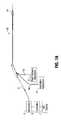
- FIG. 1Ais a schematic view of one embodiment of a system for use with the device of the present invention
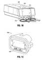
- FIG. 1Bis a perspective view of one embodiment of an integrated device incorporating features of the system shown in FIG. 1 ;
- FIG. 1Cis a perspective view of an alternate embodiment of an integrated device incorporating features of the system shown in FIG. 1 ;
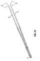
- FIG. 2Ais an isometric view of a first embodiment of the device of the present invention shown with the basket in the non-expanded position;
- FIG. 2Bis an isometric view of the device of FIG. 2A shown with the basket in the expanded position and the electrodes in the advanced (deployed) position;
- FIG. 3is an exploded isometric view of the proximal region of the device of FIG. 2A ;
- FIG. 4is an exploded isometric view of the distal region of the device of FIG. 2A ;
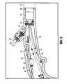
- FIG. 5is a side view with a portion of the housing removed to illustrate the internal components within the handle section and a proximal portion of the spacer with the clamp;
- FIG. 6is a side view of a portion of the housing removed to illustrate the internal components within the handle section and the proximal portion of the spacer, the clamp removed for clarity;
- FIG. 7is an isometric view of the spacer of the present invention.
- FIG. 8Ais front view of the spacer of FIG. 7 shown with the wires positioned therein;
- FIG. 8Bis a front view of an alternate embodiment of the spacer
- FIG. 9is a side perspective view of the spacer of FIG. 7 showing the wires being inserted into the spacer during a manufacturing step
- FIGS. 10 and 11are isometric and side cross-sectional views, respectively, of the spacer OF FIG. 7 ;
- FIG. 12is a side view of an alternate embodiment of the spacer of the present invention.
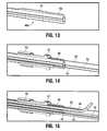
- FIG. 13is an enlarged isometric cross-sectional view of a distal portion of the spacer of FIG. 7 ;
- FIG. 14is a view similar to FIG. 13 showing the holder and clamp
- FIG. 15is a view similar to FIG. 13 showing the holder, clamp and irrigation tube;
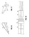
- FIGS. 16 and 17are front and back isometric views, respectively, of the irrigation manifold
- FIG. 18is a side view of the irrigation manifold of FIG. 16 with the basket arms inserted;
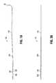
- FIG. 19is a side view of the needle electrode of the present invention.
- FIG. 20is a top view of the needle electrode of FIG. 19 ;
- FIG. 21is an enlarged view of the location feature of the electrode needle of FIG. 19 ;
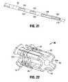
- FIG. 22is an isometric view of the needle holder
- FIG. 23Ais an isometric view showing the needle electrode of FIG. 19 being inserted into the needle holder of FIG. 22 ;
- FIG. 23Bis an isometric view similar to FIG. 23A showing the needle electrode positioned in the needle holder;
- FIG. 24is an isometric view illustrating the four needle electrodes positioned in the needle holder of FIG. 22 ;
- FIG. 25is a close up view of the needle holder and sleeve
- FIG. 26is a view similar to FIG. 25 showing the tube clamp over the needle holder sleeve
- FIG. 27is a top view of one of the basket arms (spines).
- FIG. 28is an enlarged view of the area of detail identified in FIG. 27 ;
- FIG. 29is a bottom view of the basket arm of FIG. 27 ;
- FIG. 30Ais an isometric view of one of the basket arms being inserted into the basket holder
- FIG. 30Billustrates the opposing side of the basket arm and basket holder of FIG. 30A ;
- FIG. 30Cis a cross-sectional view illustrating an alternate embodiment and showing the four arm channels engaged with the basket holder
- FIG. 31is a front view in partial cross-section showing the basket arm of FIG. 30A engaged within the basket holder;
- FIG. 32is a side view showing the basket arms positioned in the basket holder
- FIG. 33is a front view showing all four basket arms positioned in the basket holder
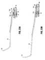
- FIG. 34Ais a front view of the device of FIG. 2A with the needle electrode in the deployed (advanced) position illustrating radial alignment of the needle tips;
- FIG. 34Bis a side view of the basket and needle electrodes in the deployed position illustrating radial and longitudinal alignment of the needle electrode tips;
- FIGS. 35A and 35Billustrate what occurs if the needle electrode tips are not radially aligned
- FIG. 35Cillustrates what occurs if the needle electrode tips are not longitudinally aligned
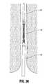
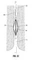
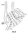
- FIGS. 36-38illustrate the method of use of the device of FIG. 2A wherein FIG. 36 shows the device inserted within a sphincter in the non-expanded condition; FIG. 37 shows the basket expanded to dilate the sphincter wall, and FIG. 38 shows the needle electrodes deployed to penetrate tissue; and
- FIG. 39illustrates the desired formation of lesions utilizing the aligned needle and basket assembly features of the present invention.
- This specificationdiscloses various systems and methods for treating dysfunction of sphincters and adjoining tissue regions in the body.
- the systems and methodsare particularly well suited for treating these dysfunctions in the upper gastrointestinal tract, e.g., gastro-esophageal reflux disease (GERD) affecting the lower esophageal sphincter and adjacent cardia of the stomach.
- GFDgastro-esophageal reflux disease
- the systems and methodswill be described in this context.
- the disclosed systems and methodsare applicable for use in treating other dysfunctions elsewhere in the body, including dysfunctions that are not necessarily sphincter-related.
- the various aspects of the inventionhave application in procedures requiring treatment of hemorrhoids, or fecal incontinence, or urinary incontinence, or restoring compliance to or otherwise tightening interior tissue or muscle regions.
- the systems and methods that embody features of the inventionare also adaptable for use with systems and surgical techniques that are catheter-based and not necessarily catheter-based.
- the systems and methods disclosed hereinprovide application of radiofrequency energy to tissue via a plurality of electrodes.
- the energyis applied via the electrodes to tissue at a series of axially spaced tissue levels, thereby forming tissue lesions which alters the tissue structure.
- Prior application of radiofrequency energy to tissue in various surgical proceduresinvolved application of energy at certain levels and for a certain period of time with the goal to ablate the tissue. That is, the objective was to cause tissue necrosis and remove tissue.
- the systems and methods of the present disclosuretreat tissue without ablating the tissue and without causing tissue necrosis, which advantageously achieves better clinical results, especially when treating the sphincter muscles of the GI tract in the specific surgical procedures disclosed herein.
- tissue reconstruction/remodelingoccurs which results in beneficial changes to tissue properties, thus beneficially treating GERD which is caused by the spontaneous relaxation of the lower esophageal sphincter and beneficially treating fecal incontinence caused by loss of tone of the sphincter muscles in the anal canal.
- the system of the present disclosurerejuvenates muscle to improve muscle function.
- the system of the present inventionalso increases the smooth muscle/connective ratio which results in sphincter reinforcement and remodeling.
- non-ablative RF energyto sphincter muscle influences the structural arrangement of smooth muscle and connective tissue contents.
- the increase of the smooth muscle fibers area per muscle bundles as well as the collagen and myofibroblast contents within the internal anal sphincterwere found to be potentially responsible for sphincter reinforcement and remodeling. More specifically, in studies, it was found that application of non-ablative RF energy increased smooth muscle/connective tissue ratio without changes (increase) in the collagen I/III ratio.
- the system and method of the present disclosureensure proper radial and longitudinal (axial) alignment of the tips of the needle electrodes. This can prevent overheating of tissue since the equidistantly spaced electrodes ensure there is no undesired overlap of tissue treatment regions which could occur if the tips were not equally radially spaced. This is especially the case since the device in use is rotated to treat lesions at the same axial lesion level and moved longitudinally to treat tissue at different axial lesion levels.
- Such radial spacing and longitudinal alignmentalso ensures that tissue is not undertreated which could occur if spacing between the needle tips is too great and therefore areas of tissue are not properly treated.
- the longitudinal spacingensures that tissue is not overheated or underheated due to undesired variations of tissue penetration/depth of energy application, compounded due to rotation and longitudinal repositioning of the device. This is discussed in more detail below.
- Preventing overheating of tissueis achieved by enhanced control of tissue treatment areas and enhanced temperature control of the tissue, which is accomplished in one way by more accurate needle tip alignment, more accurate basket alignment, and/or maintaining centering of the needle advancer during flexing of the catheter to maintain a desired depth of penetration during bending of the device.
- FIG. 1Ashows a unified system for diagnosing and/or treating dysfunction of sphincters and adjoining tissue in the body.
- the targeted sphincter regionscan vary.
- one regioncomprises the upper gastro-intestinal tract, e.g., the lower esophageal sphincter and adjacent cardia of the stomach.
- Other regionsare also contemplated.
- the device 10 of FIGS. 2A and 2Bfunction in the system to apply energy in a selective fashion to tissue in or adjoining the targeted sphincter region.
- the applied energycreates one or more lesions, or a prescribed pattern of lesions, below the surface of the targeted region without ablating tissue.
- the subsurface lesionsare desirably formed in a manner that preserves and protects the surface against thermal damage.
- the energyis applied to the muscle layer, beyond the mucosa layer.
- Natural healing of the subsurface lesionsleads to a reconstruction/remodeling of the tissue which leads to beneficial changes in properties of the targeted tissue.
- the subsurface lesionscan also result in the interruption of aberrant electrical pathways that may cause spontaneous sphincter relaxation.
- the treatmentcan restore normal closure function to the sphincter region as the non-ablating application of radiofrequency energy beneficially changes the properties of the sphincter muscle wall. Such energy rejuvenates the muscle to improve muscle function.
- the system 2includes a generator 4 to supply the treatment energy to the device 10 .
- the generator 4supplies radio frequency energy, e.g., having a frequency in the range of about 400 kHz to about 10 mHz, although other ranges are contemplated.
- Other forms of energycan be applied, e.g., coherent or incoherent light, heated or cooled fluid, resistive heating, microwave, ultrasound, a tissue ablation fluid, or cryogenic fluid.
- Device 10is coupled to the generator 4 via a cable connector 5 to convey the generated energy to the respective device 10 .
- the systempreferably also includes certain auxiliary processing equipment.
- the processing equipmentincludes an external fluid delivery apparatus 6 and an external aspiration apparatus 8 .
- Device 10can be connected via tubing 6 a to the fluid delivery apparatus 6 to convey processing fluid for discharge by or near the device 10 .
- Device 10can also be connected via tubing 8 a to the aspirating apparatus 8 to convey aspirated material by or near the device for removal.
- the systemalso includes a controller 9 .
- the controller 9which preferably includes a central processing unit (CPU), is linked to the generator 4 , and can be linked to the fluid delivery apparatus 6 , and the aspiration apparatus 8 .
- the aspiration apparatus 8can comprise a conventional vacuum source typically present in a physician's suite, which operates continuously, independent of the controller 9 .
- the controller 9governs the power levels, cycles, and duration that the radio frequency energy is distributed to the device 10 to achieve and maintain power levels appropriate to achieve the desired treatment objectives.
- the controller 9also desirably governs the delivery of processing fluid and, if desired, the removal of aspirated material.
- the controllermaintains the target tissue temperature to ensure the tissue is not overheated.
- the controller 9includes an input/output (I/O) device 7 .
- the I/O device 7allows the physician to input control and processing variables, to enable the controller to generate appropriate command signals.
- the I/O device 7also receives real time processing feedback information from one or more sensors associated with the operative element of the device (as will be described later), for processing by the controller 9 e.g., to govern the application of energy and the delivery of processing fluid.
- the I/O device 7also includes a graphical user interface (GUI), to graphically present processing information to the physician for viewing or analysis.
- GUIgraphical user interface
- the radio frequency generator, the controller with I/O device, and the fluid delivery apparatusare integrated within a single housing 200 .
- the I/O device 210couples the controller to a display microprocessor 214 .
- the display microprocessor 214is coupled to a-graphics display monitor 216 in the housing 200 .
- the controller 212implements through the display microprocessor 214 the graphical user interface, or GUI, which is displayed on the display monitor 216 .
- the graphical user interfacecan be realized with conventional graphics software using the MS WINDOWS® application.
- the GUIis implemented by showing on the monitor 216 basic screen displays.
- FIG. 1Cillustrates another embodiment where the radio frequency generator, the controller with I/O device, and the fluid delivery control apparatus (e.g., for the delivery of cooling liquid) are integrated within a single housing 200 a .
- Connection port 209is for connecting the treatment device.
- the device 10is a catheter-based device for treating sphincter regions in the upper gastro-intestinal tract, and more particularly, the lower esophageal sphincter and adjoining cardia of the stomach to treat GERD.
- the device 10includes a flexible catheter tube 22 that has a handle 16 at its proximal end. The distal end of the catheter tube 22 carries the operative element. Note that for clarity throughout the drawings not all identical components are labeled in the specific drawing.
- device 10has a proximal portion 12 , a distal portion 14 and an elongated flexible outer catheter tube 22 . Contained within the outer tube 22 is spacer 40 discussed in more detail below.
- the basket assemblyis designated generally by reference numeral 18 and is movable between a collapsed position (configuration) to provide a reduced profile for delivery and an expanded position (configuration) to dilate the tissue, e.g., the sphincter wall.
- the basket assembly 18includes a balloon 80 ( FIG. 4 ) which is inflated via inflation portion 30 extending from handle 16 to expand the basket 18 .
- an aspiration port 26to enable aspiration through the device 10 and an irrigation port 28 to enable fluid injection through the device 10 .
- the device 10also includes a plurality of needle electrodes 32 which are movable from a retracted position for delivery to an advanced position protruding through the basket for penetrating tissue.
- Plug 29extends from handle 16 and electrically communicates with a generator to apply radiofrequency to the electrodes 32 for application of such energy to treat tissue as discussed in more detail below.
- Slider 24 on handle 16is one type of mechanism (actuator) that can be used to advance the needle electrodes 32 . In this mechanism, slider 24 is movable from an initial position of FIG. 2A to a second advanced position of FIG. 2B to advance the electrodes 32 . Such advancement is achieved as rod 33 ( FIG. 3 ) is attached to the slider 24 at one end and the other end is attached to needle pusher 42 . A proximal end of the needle electrodes 32 are coupled to a distal end of the needle pusher (advancer) 42 .
- Rod 33can include a calibration nut 33 a.
- attached, connected or coupledis not limited to direct attachment, connecting or coupling as interposing components can be used.
- Spacer 40is positioned within outer tube 22 and functions to separate the various internal components and maintain a center position of needle advancer 42 .
- Needle advancer 42is slidably positioned within a central lumen of the spacer 40 .
- the irrigation tube 44which fluidly communicates with the irrigation port 28 and the arms of the basket assembly 18 and the aspiration tube 46 which communicates with the aspiration port 26 .
- the aspiration tube 46 openingis positioned proximal of the balloon 80 .
- Inflation tube 48communicates with inflation port 30 (which receives a syringe) to inflate the balloon 80 contained within the basket assembly 18 and is also positioned within spacer 40 .
- a valveis preferably provided to limit balloon inflation.
- Wires 50are also positioned within spacer 40 .
- Wire bundle 51is shown in FIG. 4 .
- Fastener 52is attached to internal threads 56 of handle 16 , with spacer clamp 54 clamping fastener 52 to connect spacer 40 to handle 16 (see also FIG. 5 ).
- FIG. 6illustrates the spacer 40 mounted within handle 16 with the clamp 54 removed for clarity.
- At least one temperature sensoris associated with each needle electrode 32 .
- One temperature sensor 108 asenses temperature conditions near the exposed distal end of the electrode 32 .
- a second temperature sensor 108 bis located on the corresponding spine 100 , which rests against the mucosal surface when the balloon structure 80 is inflated to measure temperature of the tissue adjacent the needle electrode 32 .
- the irrigation tube 44communicates with manifold 60 .
- manifold 60has an inlet opening 62 which is coupled to the irrigation tube 44 and a plurality of exit openings 64 , each communicating with one of the spines 100 of the basket assembly 18 .
- fluid entering the manifold 60 through the single inlet opening 62is subdivided for distribution through each of the four radially spaced spines 100 of the basket assembly 18 for exit through an irrigation opening in each of the spines 100 .
- the three-dimensional basket 18includes one or more spines or arms 100 , and typically includes four spines 100 , which are held together at a distal end by a distal tip 20 and at proximal end by basket holder 84 .
- four spines 100are shown, spaced circumferentially at 90-degree intervals.
- the balloon 80can be made from various materials such as by way of example, a Polyethylene Terephthalate (PET) material, or a polyamide (non-compliant) material, or a radiation cross-linked polyethylene (semi-compliant) material, or a latex material, or a silicone material, or a C-Flex (highly compliant) material.
- PETPolyethylene Terephthalate
- polyamidenon-compliant
- radiation cross-linked polyethyleneor a latex material
- silicone materialor a C-Flex (highly compliant) material.
- the balloon and basket armsare shown in FIG. 2A in a normally, generally collapsed condition, presenting a low profile for delivery into the esophagus.
- a balloon tube 82includes an interior lumen, which communicates with the interior of the balloon 80 .
- a fitting 30( FIG. 3 ), such as a syringe-activated check valve, extends from the handle 16 and communicates with the lumen in the inflation tube 48 and the lumen within the balloon tube 82 .
- the fitting 30couples the lumen to a syringe for injection of fluid under pressure through the lumen into the balloon structure 80 , causing its expansion.
- Expansion of the balloon 80urges the basket arms 100 to open and expand to the expanded position (condition) of FIG. 2B .
- the force exerted by the balloon 80 and arms 100when expanded, is sufficient to exert an opening or dilating force upon the tissue surrounding the basket arms 100 .
- the balloon 80can be expanded to varying diameters to accommodate for varying patient anatomy.
- the basket structureis composed of four basket arms or spines 100 .
- Each spine 100has three tube or spine sections 102 , 104 and 106 (see e.g. FIGS. 4 and 27 ).
- the spine 100can be formed by a tri-lumen extrusion or alternately by separate tubes attached together.
- tube 104is positioned between tubes 102 and 106 and can have flattened surfaces 104 C ( FIG. 31 ), rather than round surfaces of tubes 102 , 106 , to facilitate manufacture.
- Tube 102has a proximal opening 102 a to receive the irrigation tube 44
- tube 104has a proximal opening 104 a to receive the needle electrode 32
- tube 106has a proximal opening 106 a to receive the wires for temperature sensors 108 a , 108 b .
- the proximal openings 102 a , 104 a and 106 aare staggered, with the opening 102 a being the most proximal, the opening 106 a being the most distal and the opening 104 a axially intermediate openings 102 a and 106 a .
- Tube 102 of spine 100has an exit opening 102 b ( FIG. 28 ) to allow for exit of fluid into the tissue
- tube 104has an exit opening 104 b to enable the needle electrode 32 to be angularly deployed from the spine 100
- tube 106has an opening 106 b for the sensor 108 .
- Balloon 80positioned within the basket arms 102 , 104 , 106 has a tube 82 which is mounted within basket holder 84 .
- Basket holder clamp 86( FIG. 4 ) fixedly retains spines 100 within basket holder 84 and retains basket holder 84 within outer tube 22 .
- Basket holder clamp 86is seated within the outer tube 22 , and outer clamp 110 is positioned over outer tube 22 and over basket holder clamp 86 .
- Tube extension 88extending distally from connector tube 81 attached to balloon 80 , is connected within the central opening 25 of distal tip 20 .
- the flat ends 101 of basket arms 100connect within proximal slots 25 a of distal tip 20 .
- the basket arms (spines) 100include a location feature or structure to maintain radial alignment/spacing.
- the location featureincludes a series of grooves on the basket arms 100 which cooperate with bumps (or projections) on the basket holder 84 so the arms 100 are maintained in radial alignment with fixed radial spacing.
- a bottom surface of the tube 104 of spine 100includes a set of four grooves 112 .
- the grooves 110 on the top surface of arms 110facilitate grasping during manufacture.
- the grooves 112receive projections 89 on basket holder 84 . That is, the configuration and dimension of the grooves correspond to the configuration and dimensions of the bumps.
- this location feature of the arms 100ensures the arms are properly seated within basket holder 84 to ensure the desired alignment of the arms 100 e.g., equidistant radial spacing, is provided during manufacture and maintained during use. It should be appreciated that this location feature can alternately be configured so the projections are on the arms 100 and the grooves are in the basket holder 84 . Other location/alignment engagement features are also contemplated to maintain radial alignment of the basket arms 100 . Also, although four projections/grooves are provided in the illustrated embodiment, a different number can be utilized for the engagement structure.
- FIG. 31illustrates a cross-sectional view of one of the spines 100 mounted within the basket holder. Only one of the spines 100 is shown in FIG. 31 for clarity.
- FIG. 33is a front view (looking distally from the proximal end) showing all four arms 100 attached thereover to the basket holder 34 , with the basket holder clamp ring 86 attached to retain the holder 34 within outer tube 22 .
- lumen 114which receives the aspiration tube 46 and lumen 116 which receives the balloon inflation tube 48 .
- U-shaped channels 176can be provided and circular tubes (not shown) snapped into the channels. This is illustrated in FIG. 30C wherein three separate tubes (not shown) would be snapped into each of the four sets of channels.
- the needle pusher (advancer) 42is connected to needle electrodes 32 .
- Pusher 42is coupled at its distal end to needle holder 90 .
- Holder ring 94( FIG. 4 ) is positioned over needle holder 90 and retained by clamping sleeve 92 positioned over holder ring 94 . That is, clamping sleeve 92 is positioned over holder clamp 94 and needle holder 90 to fix the needle electrodes 32 within the needle holder 90 .
- Each spine (basket arm) 100carries an electrode 32 . Therefore, there are four electrodes circumferentially equidistantly spaced at 90-degree intervals.
- Each electrode 32is carried within the tubular member or lumen 104 of spine 100 for sliding movement from a retracted position, withdrawn within the spine 100 , to an extended position, extending outwardly from the spine 100 (see FIG. 2B ) through opening 104 a in the lumen 104 .
- a sliding actuator 24( FIGS. 3 and 5 ) on the handle 16 as described above is coupled to the sliding electrodes 32 so that the actuator 24 controls movement of the electrodes 32 between the retracted position and the extended position (by sliding the actuator from the position of FIG. 2A to the position of FIG. 2B ).
- the electrodes 32have sufficient distal sharpness and strength, when extended, to penetrate a desired depth into the smooth muscle of the lower esophageal sphincter 18 or the cardia of the stomach (see FIG. 38 ).
- the desired depthcan range from about 3 mm to about 10 mm, and more preferably between about 5 mm to about 8 mm, although other depth ranges are also contemplated.
- the electrodes 32are formed of material that conducts radio frequency energy, such as by way of example nickel titanium, stainless steel, e.g., 304 stainless steel, or a combination of nickel titanium and stainless steel.
- An electrical insulating materialcan be coated about the proximal end of each electrode so that when the distal end of the electrode penetrating the smooth muscle of the esophageal sphincter or cardia transmits radio frequency energy, the material insulates the mucosal surface of the esophagus or cardia from direct exposure to the radio frequency energy. Thermal damage to the mucosal surface is thereby avoided.
- the mucosal surfacecan also be actively cooled during application of radio frequency energy to further protect the mucosal surface from thermal damage.
- the controller 9can condition the electrodes 32 to operate in a monopolar mode. In this mode, each electrode 32 serves as a transmitter of energy, and an indifferent patch electrode (described later) serves as a common return for all electrodes 32 . Alternatively, the controller 9 can condition the electrodes 32 to operate in a bipolar mode. In this mode, one of the electrodes comprises the transmitter and another electrode comprises the return for the transmitted energy.
- the bipolar electrode pairscan include electrodes on adjacent spines, or electrodes 32 spaced apart on different spines.
- each needle electrode 32includes a location feature or structure in the form of two ribs or projections (bumps) 165 , separated by grooves 166 for cooperation with grooves 97 a formed between surfaces 97 of the needle holder 90 . That is, the projections 165 are configured and dimensioned to fit within grooves 97 a . Thus, during manufacture, the electrodes 32 are placed in alignment by a needle holder 90 . A different number of projections and cooperating grooves is also contemplated, for the engagement structure.
- the bump/groove engagementcan be a location feature which requires a clamp to maintain the position, or alternatively the location feature can interlock to frictionally engage. Also, alternatively, the projections could be provided on the needle holder and the grooves on the electrodes. Other engagement/location structure is also contemplated.
- FIG. 23Aillustrates a needle electrode 32 just before engagement with the needle holder 90 and FIG. 23B illustrates engagement of the needle electrode with the projections/grooves of the needle holder 90 .
- Each of the four needle electrodes 32are interfit to the needle holder 90 , separated at 90 degree intervals.
- Holder ring 94is then placed over the needle holder 90 ( FIG. 25 ) and clamping sleeve 92 ( FIG. 25 ) is then placed over the ring 94 to provide a clamping force to hold the proximal ends of the needle electrodes 32 engaged with the needle holder 90 , as shown in FIG. 26 .
- FIGS. 34A and 34BThe equidistant radial spacing and longitudinal alignment of the electrodes 32 a - 32 d is illustrated in FIGS. 34A and 34B with the distal tips of the electrodes extending the same distance from the basket to terminate along the same plane. This is achieved by the aforedescribed location feature
- FIGS. 35A-35Cshow misalignment.
- FIGS. 35A-35Cshow misalignment.
- FIGS. 35A-35Cshow misalignment.
- FIG. 35 aif the needle electrodes are not radially equidistantly spaced, then undertreatment and overtreatment areas will occur.
- a needle electrode 32 ais shown out of axial alignment, i.e., more than 90 degrees apart from needle electrode 32 b , and less than 90 degrees apart from needle electrode 32 d .
- the treatment areasare spaced at a minimum of 5 millimeters apart, this occurs when the electrodes are properly aligned as in the present invention.
- the treatment areaswill be equidistantly spaced between the two treatment areas T 1 and T 2 provided the electrodes are properly aligned.
- space A between treatment area T 3 and T 4is greater than 5 millimeters and space B between treatment areas T 4 and T 1 is less than 5 millimeters.
- treatment region T 7will be too close to treatment region T 4 , and can overlap region T 4 which can overtreat the tissue and cause undesired tissue ablation. Conversely, treatment area T 7 will be too far from treatment area T 3 which will lead to undertreatment of tissue. Note new treatment region T 5 is properly spaced from treatment regions T 8 and T 3 .
- FIG. 35Cillustrates what can occur if the needle electrodes are not longitudinally aligned in assembly and are deployed during use. As shown, improperly aligned electrode 32 f terminates more proximally than electrode 32 e since its initial position is improperly rearward of electrode 32 f . When the electrodes are deployed, electrode 32 f does not penetrate sufficiently into tissue so that when RF energy is applied, it will not treat the muscle layer but rather treat the mucosal layer.
- one of the needle electrodesis misaligned and is deployed too far, it can extend past the desired treatment area.
- the problemis compounded as the desired spacing between the treatment areas will not be maintained and RF energy in some regions will be applied too close to the previously treated area causing overheating and unwanted ablation and other regions will be applied too far from the previously treated region causing undertreatment.
- the basket arms 100include the location feature to engage the feature on the basket holder 84 . If the basket arms are not properly radially spaced e.g., not spaced equidistantly, then when the needle electrodes 32 are advanced through the apertures in the arms 100 , they will not be equidistantly spaced, resulting in the undertreatment/overtreatment of tissue discussed above. That is, if one of the arms 100 for example is improperly skewed so it is spaced more than 90 degrees from an adjacent arm, and closer than 90 degrees from the other adjacent arm, when the needle electrodes 32 are advanced from these arms, the tips would likewise be skewed and not spaced 90 degrees apart, resulting in the aforementioned problems of not maintaining the desired spacing.
- spacer 40has a proximal end 40 a connected to fastener 52 ( FIG. 3 ) as discussed above.
- the distal end 40 b( FIG. 4 ) connects to fastener 55 , and can be flared as shown, and is retained within outer tube 22 by distal clamp 70 .
- spacer 40has a central circular rib 142 dimensioned to slidingly receive needle pusher 42 . Emanating from the circular rib 142 are four transverse ribs 120 , 122 , 124 and 126 which subdivide the spacer 40 into four longitudinally extending quadrants 130 , 132 , 134 , and 136 .
- quadrant 130is formed between ribs 120 , 122
- quadrant 132is formed between ribs 122 and 124
- quadrant 134is formed between ribs 124 and 126
- quadrant 136is formed between ribs 126 and 120 .
- a pair of wires 50are received in each of the quadrants, best shown in FIGS. 8 and 9 , forming thermocouples for measuring tissue temperature of the tissue adjacent the needle electrodes 32 .
- the spacer 40is preferably in the form of a plastic tube formed by an extrusion. The spacer 40 also functions to maintain centering of the needle advancer during flexing of the catheter. That is, the slider/actuator 24 movement correlates one to one with movement of the needle advancer 42 and thus the needle electrodes 32 .
- the needle electrodes 32would be at a greater distance if the catheter tube 22 was bent in one direction and be at a shorter distance if the catheter 22 was bent in a different direction. This shorter distance can result in insufficient penetration resulting in undertreatment while on the other hand, movement a longer distance can result in over penetration. That is, this varied depth penetration can cause undertreatment or overtreatment which can lead to ablation of the tissue, as described in detail herein in conjunction with non-alignment of the electrodes and/or basket arms.
- the outer wall 138 of spacer 140is formed with slits to access each quadrant or area 130 , 132 , 136 , and 138 . More specifically, slit 140 a enables access to area 130 , slit 140 b enable access to area 142 , slit 140 c enables access to area 134 and slit 140 c enables access to area 136 .
- the slitis separable during manufacture so the wires 50 , irrigation tube 44 and aspiration tube 46 can be placed in the areas during manufacture. This facilitates manufacture, as the flap formed by the slit can be progressively opened and the wires and tube placed inside the area 130 - 136 , with the flap self closing to retain the components within the spacer.
- the spacercan in some embodiments be formed of a material more rigid than the outer tube. This enables a more flexible outer tube to be utilized as the spacer rather than the outer tube is utilized to provide a sufficiently rigid structure to retain the needle advancer.
- thermocouple wires 50Placement of all the wires and tubes are illustrated in FIG. 8A , with the thermocouple wires 50 placed in each of the quadrants 132 - 138 .
- Irrigation tube 44is within quadrant 134
- balloon inflation tube 48is within quadrant 138
- aspiration tube 46is within quadrant 136 .
- a rib 152extending from the outer wall transitions into circular rib 154 to retain the needle pusher 42 in a centered position within the spacer 40 .
- some wires 50 , aspiration tube 44 , and balloon inflation tube 48are placed in one quadrant and irrigation tube 44 and other wires 50 are placed in a second quadrant of the spacer 40 .
- a slit 156 a and 156 bsimilar to slits 140 a and 140 b of FIG. 8A , are provided to form a flap to enable access to the interior of the spacer in the same manner as described above.
- a different number of ribs 152can be provided to provide a different number of quadrants. For example, three ribs 152 can be provided to create three quadrants.
- spacer 240instead of a single spacer, spacer 240 includes three separate spacers 240 a , 240 b and 240 c with central lumens axially aligned. Alternatively, only two or more than three axially aligned spacers can be provided.
- the external fluid delivery apparatus 6is coupled via tubing 6 a (see FIG. 1 ) to connector 28 (see FIG. 4 ) to supply cooling liquid to the targeted tissue, e.g., through holes in the spines.
- the external aspirating apparatus 8is coupled via tubing 8 a (see FIG. 1 ) to connector or aspiration port 26 (see FIG. 3 ) to convey liquid from the targeted tissue site, e.g., through one of the tubes or lumens in the spines 100 .
- the controller 9can govern the delivery of processing fluid and, if desired, the removal of aspirated material.
- the device 10is manipulated to create a preferred pattern of multiple lesions comprising circumferential rings of lesions at several axially spaced-apart levels (about 5 mm apart), each level comprising from 8 to 12 lesions.
- a representative embodiment of the lesion patternis shown in FIG. 39 .
- the ringsare preferably formed in the esophagus in regions above the stomach, at or near the lower esophageal sphincter, and/or in the cardia of the stomach.
- the rings in the cardiaare concentrically spaced about the opening funnel of the cardia.
- the ringsare axially spaced along the esophagus.
- the deviceis inserted in the collapsed position of FIG. 36 , expanded to the position of FIG. 37 by inflation of the balloon to dilate the sphincter and then the needle electrodes 32 are advanced into tissue as shown in FIG. 38 for application of energy.
- Multiple lesion patternscan be created by successive extension and retraction of the electrodes 32 , accompanied by rotation and/or axial movement of the catheter tube to reposition the basket assembly 18 .
- the physiciancan create a given ring pattern by expanding the balloon structure 80 and extending the electrodes 32 at the targeted treatment site, to form a first set of four lesions.
- the physiciancan then withdraw the electrodes 32 , collapse the balloon structure 80 , and rotate the catheter tube 22 by a desired amount, e.g., 30-degrees or 45-degrees, depending upon the number of total lesions desired within 360-degrees.
- the physiciancan then again expand the structure 18 and again extend the electrodes 32 , to achieve a second set of four lesions.
- the physicianrepeats this sequence until a desired number of lesions within the 360-degree extent of the ring is formed. Additional lesions can be created at different levels by advancing the operative element axially, gauging the ring separation by external markings on the catheter tube.
- a desirable patterncomprises an axially spaced pattern of six circumferential lesions numbered Level 1 to Level 6 in an inferior direction, with some layers in the cardia of the stomach, and others in the esophagus above the stomach at or near the lower esophageal sphincter.
- there are eight lesions circumferentially spaced 45-degrees aparti.e., a first application of energy, followed by a 45-degree rotation of the basket 56 , followed by a second application of energy).
- Levels 5 and 6there are twelve lesions circumferentially spaced 30-degrees apart (i.e., a first application of energy, followed by a 30-degree rotation of the basket 56 , followed by a second application of energy, followed by a 30-degree rotation of the basket assembly 18 , followed by a third application of energy).
- the balloon 80is only partially expanded, whereas in Level 6, the balloon 80 is more fully expanded, to provide lesion patterns that increase in circumference according to the funnel-shaped space available in the funnel of the cardia.
- a pressure relief valveis attached to the air syringe, upstream of the balloon inflation port of the device, to allow air to escape if pressure levels are exceeded. That is, in Levels 1-4, the air syringe is filled with air, and the balloon is inflated to a target pressure so there is enough contact to slightly tension the tissue but not enough to stretch the tissue, with the pressure relief ensuring the pressure is not exceeded.
- the balloonwould be inflated to no more than about 2.5 psi.
- the balloonIn the stomach, at Levels 5 and 6, there is more room for the balloon inflation, so the balloon can be further inflated and the pressure relief valve can be removed.
- the balloonis preferably inflated by volume to about 25 ml for treatment at Level 5, and after treatment at Level 5, deflated at Level 6 to about 22 ml.
- the inflated ballooncan also be used as an anchor.
- Level 5after treatment of Level 4 the balloon is deflated and the instrument is advanced, then retracted, wherein Level 6 is treated, then the instrument is pulled further proximally to subsequently treat Level 5.
- Level 5can be considered in order of energy application so that it is distal of Level 6 and therefore being more distal, treated before Level 6.
- the balloonwould still be inflated to about 25 ml in the more distal level and to about 22 ml in this embodiment.
- the ballooncan also serve as an anchor.
- one or more digital camerascan be mounted along the catheter tube, e.g., with the camera lens directed to the basket assembly 18 , to provide visualization of the site.
- the catheter tubecan be designed to fit within a lumen of an endoscope, relying on the endoscope for visualization of the site.
- the GUIdisplays an appropriate start-up logo and title image (not shown), while the controller 52 performs a self-test.
- An array of SETUP prompts 502leads the operator in a step-wise fashion through the tasks required to enable use of the generator and device.
- the GUIis described in detail in U.S. Patent Publication No. 2011/0112529, the entire contents of which are incorporated herein by reference and therefore for brevity is not repeated herein.
- the physiciancan couple the source of cooling liquid to the appropriate port on the handle of the device 10 and load the tubing leading from the source of cooling liquid (e.g., a bag containing sterile water) into the pump.
- the physiciancan also couple the aspiration source 8 to the appropriate port on the handle of the treatment device 10 .
- a graphic field of the GUIdisplays one or more icons and/or alpha-numeric indicia that prompt the operator to connect the return patch electrode, connect the foot pedal or switch, connect the selected treatment device 10 and to prime the irrigation pump.
- the usercontrols the pump speed to increase fluid flow if the temperature is rising.
- the systemis designed with an automatic cooling feature, thus enabling quicker application of cooling fluid to address rising tissue temperatures to faster cool the tissue surface which in turn cools the underlying tissue which helps to maintain the tissue temperature below the “tissue ablation threshold.”
- the speed of the pumpis changed automatically to reduce the temperature. That is, if the tissue surface temperature, e.g., at the mucosa layer as measured by the tissue temperature sensor, reaches a certain threshold (a “first value”), the pump speed will increase to pump more cooling fluid to the tissue.
- a certain thresholde.g., a “first value”
- the systemcan enable the user to override the automatic pump to reduce the fluid flow.
- a user override featureis not provided.
- the systemis preferably designed so that if a second predetermined higher temperature value (“second value”) is reached, the pump is automatically moved to its maximum pump speed, which preferably cannot be overridden by the user.
- the electrode channelis disabled as discussed herein to shut off energy flow to that electrode. Consequently, before the third cut off value is reached, as the temperature is rising, the system provides for a quicker response to the rising temperature by automatically increasing fluid flow, rather than relying on the slower response time of the user to implement the pump speed change, thereby helping to keep temperature below the tissue ablation threshold temperature.
- Exemplary tissue valuesare provided solely by way of example, it being understood that other tissue values can also be utilized to achieve quick application of cooling fluid and ensure the non-ablation, and non-burning, of tissue.
- the first valuecould be about 38 degrees
- the second valuecould be about 40 degrees
- the third value where the energy is shut downcould be about 43 degrees.
- the first valuecould be about 45 degrees
- the second valuecould be about 46 degrees
- the third value where the energy is shut downcould be about 54 degrees.
- the identification code for the deviceis part of a printed circuit board (PCB) positioned in the handle of the treatment device.
- the PCBprocesses the calculated parameters.
- the PCBin conjunction with thermocouples provides a temperature measurement mechanism.
- the PCBmeasures the voltage generated by the thermocouples, converts it from an analog to a digital value and stores it in the internal memory.
- the PCBcommunicates the digital data to the generator. This step is performed during the 100 millisecond break between radiofrequency pulses discussed below.
- the temperature measurement mechanismin the treatment device, i.e., in the disposable handpiece, rather than in the housing 400 , data collection is closer to the source which translates into less noise susceptibility and improved accuracy. That is, since processing of temperature values occurs closer to the tissue and electrode tip, measurements can be more accurate. More accurate readings translate into tighter power controls and better clinical results and it better ensures the tissue is not ablated during treatment as it is maintained below a tissue ablation threshold.
- the PCBwhich is asymmetrically positioned within the handle, is shielded to reduce interference which could otherwise disrupt communication between the disposable treatment device and the generator.
- interferencenoise
- the shieldis a copper foil, although other ways to shield the PCB are also contemplated.
- the disruption of communicationcould adversely affect processing and evaluation of the data collected by the treatment device. By eliminating such disruptions, and thereby disabling fewer electrodes, improved consistency of treatment is achieved. Also, as can be appreciated, if too many electrodes are disabled in a procedure, the tissue may not be sufficiently thermally treated to achieve the desired clinical result.
- the identification codeis positioned in the handle of the treatment device 10 , but the other hardware, e.g., the printed circuit board for temperature calculation, etc. is outside the handle.
- the temperature data collectionis performed outside the disposable treatment device which reduces costs since it need not be disposed of with the disposable treatment device. Note these embodiments still have the advantage of data collection closer to the source than if in the housing 400 .
- the controller 52Upon completion of the SET-UP operation, the controller 52 proceeds to condition the generator and ancillary equipment to proceed step-wise through a sequence of operational modes.
- the operational modeshave been preprogrammed to achieve the treatment protocol and objective of the selected device 10 .
- the Flow Rate/Priming Iconshows the selected pump speed by the number of bars, one bar highlighting a low speed, two bars highlighting a medium speed, and three bars highlighting a high speed.
- Each GUIincludes an Electrode Icon comprising an idealized graphical image, which spatially models the particular multiple electrode geometry of the device that has been coupled to the controller 42 . This is illustrated and described in detail in U.S. Patent Publication No. 2011/0112529.
- temperature of the needle tipsis measured when the needles are deployed at the lesion level, but prior to application of RF energy. If the measured temperature exceeds an expected value, the temperature reading alerts the user that the needle position might need to be readjusted. If the temperature value is too high, this can mean that the electrode position is too close to the previous tissue level treated, and thereby the user can readjust the electrode position by increasing the spacing, thereby reducing the chances of overtreating the tissue which can cause undesired tissue ablation or burning of tissue. Consequently, continuous treatment of tissue can be achieved with reduced overlapping of treatment.
- the temperature of the electrode tip, the tissue temperature and the impedance, along with other safety parameters, such as adequate connections,are monitored during the procedure to ensure energy flow is correct. This includes proper flow through the cable, electrodes, ground pad, etc.
- the electrode needleis then disabled if a safety condition is suspected and indicated. Each needle can be controlled separately.
- impedanceis intermittently checked throughout the procedure. Impedance is measured by measuring the current at the channel of the electrode tip. The impedance monitoring provides an indication of how well the treatment device is connected and communicating with the tissue, which includes the needle penetration and the path with the return pad. If there is not good contact between the electrode and tissue, impedance is high and a patient can get burned. Therefore, if a patient moves, needle penetration could be affected. However, oftentimes a minor adjustment can be made which does not require shutting down energy flow. To avoid premature shutting down of the system a multiple error check is conducted by the system which is described in more detail below. This multiple error check reduces the incidence of needle disabling which in turn reduces the incidence of undertreatment.
- the impedanceis measured by applying a voltage, measuring the current and calculating the impedance.
- the RF energyis applied in 0.9 second intervals, with a 0.1 second break in between where an artificial pulse is sent for 0.1 second, in which impedance is measured.
- the temperature of the electrode tip and tissue temperatureis also measured during this 0.1 second interval, for calculating such measurement.
- the RF energyis repeatedly applied for 0.9 seconds, with 0.1 second “measurement intervals” for a time period of 60 seconds.
- the Lesion Level Iconcomprises an idealized graphical image, which spatially models the desired lesion levels and the number of lesions in each level, described in detail in Patent Publication 2011/0112529. As described in this publication, the Lesion Level Icons change in real time, to step-wise guide the physician through the procedure and to record the progress of the procedure from start to finish.
- the GUIgraphically changes the display of the Lesion Levels, depending upon the status of lesion formation within the respective levels.
- the Lesion Level Iconsinclude a series of segmented circles. The open segments remaining in the segmented circle prompt the physician to rotate the basket by 45-degrees, and actuate the electrodes for second time. After the pre-set period (tracked by the Timer Icon), more treatment indicia (the dots) appear in the remaining segments of the circle. This indicates that all the lesions prescribed for Lesion Level 1 have been formed, and to deflate the basket and move to the next treatment level.
- the Marker that is displayeddirects the physician to Lesion Level 2, which is 5 mm below Lesion Level 1.
- the Balloon Iconcan reappear to prompt the physician to deflate the balloon.
- the physicianis thereby prompted to deflate the basket, move to Lesion Level 2, and expand the basket.
- the GUIchanges the graphical form of Lesion Level 1 back to an edgewise cylinder.
- the edgewise cylinder for Lesion Level 1includes an indicator, e.g., checkmark, to indicate that Lesion Level 1 has been treated.
- the insertion of the treatment completed indicatoris yet another graphical form the GUI displays to communicate status information to the physician.
- the physicianactuates the electrodes for a first pre-set period, then rotates the device 45-degrees, and actuates the electrodes for the second pre-set period.
- the Timer Iconreflects the application of radio frequency energy for the pre-set periods, and the treatment indicia (e.g., dots) are added to the segments of the graphical segmented circle, indicating the formation of the first four lesions and the next four lesions, as well as their spatial orientation.
- the physicianis thereby prompted to deflate the basket, move to Lesion Level 3, and expand the basket upon sensing electrode impedance, indicating contact with tissue at Lesion Level 3.
- Lesion Level 3The physician proceeds to form eight lesions in Lesion Level 3 then moving on to Lesion Level 4. All the while, the GUI visually records and confirms progress.
- Lesion Levels 5 and 6twelve lesions are to be formed. In the Levels 5 and 6, there are twelve lesions circumferentially spaced 30-degrees apart (i.e., a first application of energy, followed by a 30-degree rotation of the basket 18 , followed by a second application of energy, followed by a 30-degree rotation of the basket 18 , followed by a third application of energy).
- Level 5the balloon structure is only partially expanded, whereas in Level 6, the balloon structure is more fully expanded, to provide lesion patterns that increase in circumference according to the funnel-shaped space available in the funnel of the cardia.
- the GUIby purposeful manipulation of different stylized graphical images, visually prompts the physician step wise to perform a process of forming a pattern of lesions comprising a plurality of axially spaced lesion levels, each lesion level comprising a plurality of circumferential spaced lesions.
- the GUIregisters the formation of lesions as they are generated in real time, both within and between each circumferentially spaced level.
- the GUItherefore displays for the physician a visual record of the progress of the process from start to finish.
- the GUIassures that individual lesions desired within a given level are not skipped, or that a given level of lesions is not skipped.
- each Lesion Level 1 to 6is initially depicted by a first stylized graphical image comprising an edgewise cylinder with a number identification of its level.
- the GUIchanges the first stylized graphical image into a second stylized graphical image, different than the first image, comprising an axial view of the cylinder, presented as a segmented circle, with the numbers of segments corresponding to the number of lesions to be formed.
- the next lesion level to be treatedstill displayed as an edgewise cylinder
- a markeralong with a number indicating its distance from the present legion level.
- the second graphical imagefurther changes to a third graphical image, different than the first or second images, by adding indicia within the segmented circle to reflect the formation of lesions, to guide the physician to successively rotate and operate the device at the lesion level.
- the UGUIagain changes the third graphical image to a fourth graphical image, different than the first, second, and third graphical images, comprising an edgewise cylinder with a number identification of its level, and further an indicator (e.g. a check mark) that indicates all desired lesions have been formed at the respective level.
- a Markeris successively updated to direct the physician to the next Lesion Level.
- the GUIprompts the formation of eight lesions circumferentially spaced 45-degrees apart in the Levels 1, 2, 3, and 4, and the formation of twelve lesions circumferentially spaced 30-degrees apart at Lesion Levels 5 and 6.
- a total of 56 lesionscan be formed in this procedure.
- certain error messagesare graphically indicated on the GUI. Certain of these error messages relate to user errors which could be in the user's control, and therefore could potentially be correctable by the user. For example, if there is an error in the treatment device connection, the generator returns to the set up screen and the icon representing the treatment device displayed by the GUI begins flashing. Another example is if the error relates to the return pad, e.g., improper placement or contact of the pad, the generator likewise returns to the set up screen and the return pad icon displayed by the GUI begins flashing. Another example is if the needles are not treated or positioned properly.
- the usercan attempt to make the proper adjustments, e.g., check the connection of the treatment device, adjust the position of the return pad, etc.
- the systemwill shut down fewer times thereby enabling the creation of more lesions.
- the instrumentcontinuously measures temperature which is transmitted back to the generator. The generator expects the temperature to be in a certain range. If the temperature does not appear right, e.g., is outside an expected range, if the RF channel was immediately shut down, then it could result in premature/unnecessary termination of RF energy which could undertreat tissue. Therefore, the present invention provides steps to ensure a shut down result is truly necessary, thus advantageously limiting undertreatment of the tissue.
- the systemdue to its faster processing speed which enables faster processing of data and faster adjustment of parameters, enables rechecking of detected errors to reduce the instances of prematurely shutting down energy flow to an electrode.
- premature termination of energy flowcan result in insufficient application of thermal energy which in turn can result in undertreatment of tissue.
- the systemadvantageously is designed to reduce the number of events that would lead to energy cutoff to an electrode. More specifically, during the treatment cycles, oftentimes an error is detected which can be readily addressed by the user, such as by a small adjustment of the treatment device position if the error is caused for example by patient movement which affects the impedance reading, or even self-adjusts. If the system was designed to immediately shut down upon such error detection, then the electrode would be disabled and the lesion might not be created in that tissue region. Therefore, to reduce these occurrences, the system has been designed to recheck certain errors.
- the systemdoes not permanently interrupt energy flow on the first error reading, but suspends energy flow until a second check of the system is performed. If on the second check the error is no longer detected, energy flow is resumed. However, if on the second check, e.g., re-measurement/calculation, an error still exists, the system runs yet a third check. If the error no longer exists, the energy flow resumes; if the error still exists, energy flow is cut off to that electrode at that treatment position. Consequently, only after the system runs a triple check is a final determination made to either transition back to energy flow or record the error and disable the electrode channel, i.e., shut down RF energy flow to that electrode.
- the errorcan be checked multiple times to ensure it actually requires interruption of energy flow, thus avoiding premature disabling of an electrode to thereby enhance tissue treatment by not skipping tissue levels, or regions (quadrants) within each tissue level which could otherwise have been treated. As a result, a more comprehensive and uniform tissue treatment is achieved.
- This triple error checking featureexemplifies the speed of the processor which enables quicker processing of temperature calculations and quicker response to address rising temperatures so the tissue is not treated above the tissue ablation threshold.
- this tissue ablation thresholdcan be exceeded if the energy is applied for too long a duration and/or too high a setting such that the tissue temperature rises or applied for too long a duration once the tissue temperature has reached the tissue ablation threshold before the flow of energy is terminated.
- maintaining the proper axial distance of the electrodespreferably with the tips terminating at the same distal distance from the respective spine, and maintaining the proper radial distance of the tips, preferably evenly spaced along a circumference, will aid in maintaining the treatment between the lower threshold and maximum value threshold, i.e., between undertreatment and overtreatment.
- the systemalso avoids ablating tissue due to careful and more accurate calibration of the tissue temperature measurement mechanism. This is basically achieved by precisely calibrating the PCB so it can read the voltage generated by the thermocouples more accurately, reducing the likelihood of heating tissue beyond the tissue ablation threshold.
- the PCBenables more accurate temperature measurements which in turn allows the system to disable or make the appropriate adjustment, e.g., increasing cooling fluid application, when the temperature limits are reached.
- the centering of the needle pusher and attached electrodes, the alignment of the electrodes and the alignment of the basket armsmaintain proper treatment zones to ensure the tissue is treated between the range of undertreatment and overtreatment.
Landscapes
- Engineering & Computer Science (AREA)
- Health & Medical Sciences (AREA)
- Life Sciences & Earth Sciences (AREA)
- Surgery (AREA)
- Animal Behavior & Ethology (AREA)
- Public Health (AREA)
- Veterinary Medicine (AREA)
- Nuclear Medicine, Radiotherapy & Molecular Imaging (AREA)
- General Health & Medical Sciences (AREA)
- Molecular Biology (AREA)
- Medical Informatics (AREA)
- Biomedical Technology (AREA)
- Heart & Thoracic Surgery (AREA)
- Physics & Mathematics (AREA)
- Plasma & Fusion (AREA)
- Otolaryngology (AREA)
- Human Computer Interaction (AREA)
- General Engineering & Computer Science (AREA)
- Theoretical Computer Science (AREA)
- Robotics (AREA)
- General Physics & Mathematics (AREA)
- Surgical Instruments (AREA)
Abstract
Description
- a. providing a device having a plurality of electrodes movable between a retracted position and an extended position, the plurality of electrodes having structure to maintain an equidistant radial spacing and to maintain longitudinal alignment of penetrating tips of the electrodes in the retracted position;
- b. inserting the device into the sphincter of a patient;
- c. advancing the electrodes to penetrate sphincter tissue at a first location, the electrodes having penetrating tips longitudinally aligned in the advanced position and further being equidistantly radially spaced in the advanced position;
- d. applying radio frequency energy to the electrodes to apply radiofrequency energy to tissue in the area of the penetrating tips of the electrodes, the energy applied so a minimum distance is maintained between regions of tissue treated by the electrodes;
- e. retracting the electrodes within the device;
- f. rotating the device to a second position;
- g. advancing the electrodes from the device so that the penetrating tips penetrate sphincter tissue at a second location, the penetrating tips of the electrodes being longitudinally aligned and maintained in an equidistant radial spacing; and
- h. applying radiofrequency energy to the electrodes to apply radiofrequency energy to tissue in the area of the penetrating tips of the electrodes, such fixed radial spacing and longitudinal alignment maintain the minimum distance between the regions of tissue treated to avoid overlapping of tissue treatment area which could cause ablation of tissue.
Claims (20)
Priority Applications (8)
| Application Number | Priority Date | Filing Date | Title |
|---|---|---|---|
| US14/708,210US9750563B2 (en) | 2009-09-22 | 2015-05-09 | Systems and methods for treating tissue with radiofrequency energy |
| PCT/US2015/031660WO2015187361A1 (en) | 2014-06-07 | 2015-05-20 | Systems and methods for treating tissue with radiofrequency energy |
| EP15726484.7AEP3151771A1 (en) | 2014-06-07 | 2015-05-20 | Systems and methods for treating tissue with radiofrequency energy |
| US14/866,664US20160015451A1 (en) | 2009-09-22 | 2015-09-25 | Systems and methods for treating tissue with radiofrequency energy |
| US15/675,584US10363089B2 (en) | 2009-09-22 | 2017-08-11 | Systems and methods for treating tissue with radiofrequency energy |
| US16/510,899US11471214B2 (en) | 2009-09-22 | 2019-07-13 | Systems and methods for treating tissue with radiofrequency energy |
| US17/964,091US20230122245A1 (en) | 2009-09-22 | 2022-10-12 | Systems and methods for treating tissue with radiofrequency eneregy |
| US18/582,795US20240189020A1 (en) | 2014-06-07 | 2024-02-21 | Systems and methods for treating tissue with radiofrequency eneregy |
Applications Claiming Priority (6)
| Application Number | Priority Date | Filing Date | Title |
|---|---|---|---|
| US27726009P | 2009-09-22 | 2009-09-22 | |
| US12/924,155US20110112529A1 (en) | 2009-09-22 | 2010-09-22 | Systems and methods for controlling use and operation of a family of different treatment devices |
| US201261664960P | 2012-06-27 | 2012-06-27 | |
| US13/867,042US9474565B2 (en) | 2009-09-22 | 2013-04-20 | Systems and methods for treating tissue with radiofrequency energy |
| US201462009223P | 2014-06-07 | 2014-06-07 | |
| US14/708,210US9750563B2 (en) | 2009-09-22 | 2015-05-09 | Systems and methods for treating tissue with radiofrequency energy |
Related Parent Applications (1)
| Application Number | Title | Priority Date | Filing Date |
|---|---|---|---|
| US13/867,042Continuation-In-PartUS9474565B2 (en) | 2009-09-22 | 2013-04-20 | Systems and methods for treating tissue with radiofrequency energy |
Related Child Applications (2)
| Application Number | Title | Priority Date | Filing Date |
|---|---|---|---|
| US14/866,664Continuation-In-PartUS20160015451A1 (en) | 2009-09-22 | 2015-09-25 | Systems and methods for treating tissue with radiofrequency energy |
| US15/675,584DivisionUS10363089B2 (en) | 2009-09-22 | 2017-08-11 | Systems and methods for treating tissue with radiofrequency energy |
Publications (2)
| Publication Number | Publication Date |
|---|---|
| US20150238251A1 US20150238251A1 (en) | 2015-08-27 |
| US9750563B2true US9750563B2 (en) | 2017-09-05 |
Family
ID=53881119
Family Applications (4)
| Application Number | Title | Priority Date | Filing Date |
|---|---|---|---|
| US14/708,210Expired - Fee RelatedUS9750563B2 (en) | 2009-09-22 | 2015-05-09 | Systems and methods for treating tissue with radiofrequency energy |
| US15/675,584ActiveUS10363089B2 (en) | 2009-09-22 | 2017-08-11 | Systems and methods for treating tissue with radiofrequency energy |
| US16/510,899Active2032-04-01US11471214B2 (en) | 2009-09-22 | 2019-07-13 | Systems and methods for treating tissue with radiofrequency energy |
| US17/964,091AbandonedUS20230122245A1 (en) | 2009-09-22 | 2022-10-12 | Systems and methods for treating tissue with radiofrequency eneregy |
Family Applications After (3)
| Application Number | Title | Priority Date | Filing Date |
|---|---|---|---|
| US15/675,584ActiveUS10363089B2 (en) | 2009-09-22 | 2017-08-11 | Systems and methods for treating tissue with radiofrequency energy |
| US16/510,899Active2032-04-01US11471214B2 (en) | 2009-09-22 | 2019-07-13 | Systems and methods for treating tissue with radiofrequency energy |
| US17/964,091AbandonedUS20230122245A1 (en) | 2009-09-22 | 2022-10-12 | Systems and methods for treating tissue with radiofrequency eneregy |
Country Status (1)
| Country | Link |
|---|---|
| US (4) | US9750563B2 (en) |
Cited By (133)
| Publication number | Priority date | Publication date | Assignee | Title |
|---|---|---|---|---|
| USD924139S1 (en) | 2019-09-05 | 2021-07-06 | Ethicon Llc | Energy module with a backplane connector |
| USD928725S1 (en) | 2019-09-05 | 2021-08-24 | Cilag Gmbh International | Energy module |
| USD928726S1 (en) | 2019-09-05 | 2021-08-24 | Cilag Gmbh International | Energy module monopolar port |
| USD939545S1 (en) | 2019-09-05 | 2021-12-28 | Cilag Gmbh International | Display panel or portion thereof with graphical user interface for energy module |
| US11218822B2 (en) | 2019-03-29 | 2022-01-04 | Cilag Gmbh International | Audio tone construction for an energy module of a modular energy system |
| US11234756B2 (en) | 2017-12-28 | 2022-02-01 | Cilag Gmbh International | Powered surgical tool with predefined adjustable control algorithm for controlling end effector parameter |
| US11253315B2 (en) | 2017-12-28 | 2022-02-22 | Cilag Gmbh International | Increasing radio frequency to create pad-less monopolar loop |
| US11259830B2 (en) | 2018-03-08 | 2022-03-01 | Cilag Gmbh International | Methods for controlling temperature in ultrasonic device |
| US11259807B2 (en) | 2019-02-19 | 2022-03-01 | Cilag Gmbh International | Staple cartridges with cam surfaces configured to engage primary and secondary portions of a lockout of a surgical stapling device |
| US11266468B2 (en) | 2017-12-28 | 2022-03-08 | Cilag Gmbh International | Cooperative utilization of data derived from secondary sources by intelligent surgical hubs |
| US11278280B2 (en) | 2018-03-28 | 2022-03-22 | Cilag Gmbh International | Surgical instrument comprising a jaw closure lockout |
| US11278281B2 (en) | 2017-12-28 | 2022-03-22 | Cilag Gmbh International | Interactive surgical system |
| US11284936B2 (en) | 2017-12-28 | 2022-03-29 | Cilag Gmbh International | Surgical instrument having a flexible electrode |
| US11291510B2 (en) | 2017-10-30 | 2022-04-05 | Cilag Gmbh International | Method of hub communication with surgical instrument systems |
| US11291495B2 (en) | 2017-12-28 | 2022-04-05 | Cilag Gmbh International | Interruption of energy due to inadvertent capacitive coupling |
| US11298148B2 (en) | 2018-03-08 | 2022-04-12 | Cilag Gmbh International | Live time tissue classification using electrical parameters |
| US11304745B2 (en) | 2017-12-28 | 2022-04-19 | Cilag Gmbh International | Surgical evacuation sensing and display |
| US11304699B2 (en) | 2017-12-28 | 2022-04-19 | Cilag Gmbh International | Method for adaptive control schemes for surgical network control and interaction |
| US11304763B2 (en) | 2017-12-28 | 2022-04-19 | Cilag Gmbh International | Image capturing of the areas outside the abdomen to improve placement and control of a surgical device in use |
| US11304720B2 (en) | 2017-12-28 | 2022-04-19 | Cilag Gmbh International | Activation of energy devices |
| US11308075B2 (en) | 2017-12-28 | 2022-04-19 | Cilag Gmbh International | Surgical network, instrument, and cloud responses based on validation of received dataset and authentication of its source and integrity |
| US11311306B2 (en) | 2017-12-28 | 2022-04-26 | Cilag Gmbh International | Surgical systems for detecting end effector tissue distribution irregularities |
| US11311342B2 (en) | 2017-10-30 | 2022-04-26 | Cilag Gmbh International | Method for communicating with surgical instrument systems |
| US11317937B2 (en) | 2018-03-08 | 2022-05-03 | Cilag Gmbh International | Determining the state of an ultrasonic end effector |
| USD950728S1 (en) | 2019-06-25 | 2022-05-03 | Cilag Gmbh International | Surgical staple cartridge |
| US11317915B2 (en) | 2019-02-19 | 2022-05-03 | Cilag Gmbh International | Universal cartridge based key feature that unlocks multiple lockout arrangements in different surgical staplers |
| US11317919B2 (en) | 2017-10-30 | 2022-05-03 | Cilag Gmbh International | Clip applier comprising a clip crimping system |
| US11324557B2 (en) | 2017-12-28 | 2022-05-10 | Cilag Gmbh International | Surgical instrument with a sensing array |
| USD952144S1 (en) | 2019-06-25 | 2022-05-17 | Cilag Gmbh International | Surgical staple cartridge retainer with firing system authentication key |
| US11337746B2 (en) | 2018-03-08 | 2022-05-24 | Cilag Gmbh International | Smart blade and power pulsing |
| US11350978B2 (en) | 2018-09-07 | 2022-06-07 | Cilag Gmbh International | Flexible neutral electrode |
| US11357503B2 (en) | 2019-02-19 | 2022-06-14 | Cilag Gmbh International | Staple cartridge retainers with frangible retention features and methods of using same |
| US11364075B2 (en) | 2017-12-28 | 2022-06-21 | Cilag Gmbh International | Radio frequency energy device for delivering combined electrical signals |
| US11369377B2 (en) | 2019-02-19 | 2022-06-28 | Cilag Gmbh International | Surgical stapling assembly with cartridge based retainer configured to unlock a firing lockout |
| US11382697B2 (en) | 2017-12-28 | 2022-07-12 | Cilag Gmbh International | Surgical instruments comprising button circuits |
| US11389164B2 (en) | 2017-12-28 | 2022-07-19 | Cilag Gmbh International | Method of using reinforced flexible circuits with multiple sensors to optimize performance of radio frequency devices |
| US11406390B2 (en) | 2017-10-30 | 2022-08-09 | Cilag Gmbh International | Clip applier comprising interchangeable clip reloads |
| US11410259B2 (en) | 2017-12-28 | 2022-08-09 | Cilag Gmbh International | Adaptive control program updates for surgical devices |
| US11406382B2 (en) | 2018-03-28 | 2022-08-09 | Cilag Gmbh International | Staple cartridge comprising a lockout key configured to lift a firing member |
| US11424027B2 (en) | 2017-12-28 | 2022-08-23 | Cilag Gmbh International | Method for operating surgical instrument systems |
| US11419630B2 (en) | 2017-12-28 | 2022-08-23 | Cilag Gmbh International | Surgical system distributed processing |
| US11423007B2 (en) | 2017-12-28 | 2022-08-23 | Cilag Gmbh International | Adjustment of device control programs based on stratified contextual data in addition to the data |
| US11419667B2 (en) | 2017-12-28 | 2022-08-23 | Cilag Gmbh International | Ultrasonic energy device which varies pressure applied by clamp arm to provide threshold control pressure at a cut progression location |
| US11432885B2 (en) | 2017-12-28 | 2022-09-06 | Cilag Gmbh International | Sensing arrangements for robot-assisted surgical platforms |
| USD964564S1 (en) | 2019-06-25 | 2022-09-20 | Cilag Gmbh International | Surgical staple cartridge retainer with a closure system authentication key |
| US11446052B2 (en) | 2017-12-28 | 2022-09-20 | Cilag Gmbh International | Variation of radio frequency and ultrasonic power level in cooperation with varying clamp arm pressure to achieve predefined heat flux or power applied to tissue |
| US11464559B2 (en) | 2017-12-28 | 2022-10-11 | Cilag Gmbh International | Estimating state of ultrasonic end effector and control system therefor |
| US11464535B2 (en) | 2017-12-28 | 2022-10-11 | Cilag Gmbh International | Detection of end effector emersion in liquid |
| US11464511B2 (en) | 2019-02-19 | 2022-10-11 | Cilag Gmbh International | Surgical staple cartridges with movable authentication key arrangements |
| US11471156B2 (en) | 2018-03-28 | 2022-10-18 | Cilag Gmbh International | Surgical stapling devices with improved rotary driven closure systems |
| US11504192B2 (en) | 2014-10-30 | 2022-11-22 | Cilag Gmbh International | Method of hub communication with surgical instrument systems |
| US11510741B2 (en) | 2017-10-30 | 2022-11-29 | Cilag Gmbh International | Method for producing a surgical instrument comprising a smart electrical system |
| US11529187B2 (en) | 2017-12-28 | 2022-12-20 | Cilag Gmbh International | Surgical evacuation sensor arrangements |
| US11540855B2 (en) | 2017-12-28 | 2023-01-03 | Cilag Gmbh International | Controlling activation of an ultrasonic surgical instrument according to the presence of tissue |
| US11559307B2 (en) | 2017-12-28 | 2023-01-24 | Cilag Gmbh International | Method of robotic hub communication, detection, and control |
| US11559308B2 (en) | 2017-12-28 | 2023-01-24 | Cilag Gmbh International | Method for smart energy device infrastructure |
| US11564703B2 (en) | 2017-10-30 | 2023-01-31 | Cilag Gmbh International | Surgical suturing instrument comprising a capture width which is larger than trocar diameter |
| US11564756B2 (en) | 2017-10-30 | 2023-01-31 | Cilag Gmbh International | Method of hub communication with surgical instrument systems |
| US11571234B2 (en) | 2017-12-28 | 2023-02-07 | Cilag Gmbh International | Temperature control of ultrasonic end effector and control system therefor |
| US11576677B2 (en) | 2017-12-28 | 2023-02-14 | Cilag Gmbh International | Method of hub communication, processing, display, and cloud analytics |
| US11589865B2 (en) | 2018-03-28 | 2023-02-28 | Cilag Gmbh International | Methods for controlling a powered surgical stapler that has separate rotary closure and firing systems |
| US11589888B2 (en) | 2017-12-28 | 2023-02-28 | Cilag Gmbh International | Method for controlling smart energy devices |
| US11589932B2 (en) | 2017-12-28 | 2023-02-28 | Cilag Gmbh International | Usage and technique analysis of surgeon / staff performance against a baseline to optimize device utilization and performance for both current and future procedures |
| US11596291B2 (en) | 2017-12-28 | 2023-03-07 | Cilag Gmbh International | Method of compressing tissue within a stapling device and simultaneously displaying of the location of the tissue within the jaws |
| US11601371B2 (en) | 2017-12-28 | 2023-03-07 | Cilag Gmbh International | Surgical network determination of prioritization of communication, interaction, or processing based on system or device needs |
| US11602393B2 (en) | 2017-12-28 | 2023-03-14 | Cilag Gmbh International | Surgical evacuation sensing and generator control |
| US11612408B2 (en) | 2017-12-28 | 2023-03-28 | Cilag Gmbh International | Determining tissue composition via an ultrasonic system |
| US11612444B2 (en) | 2017-12-28 | 2023-03-28 | Cilag Gmbh International | Adjustment of a surgical device function based on situational awareness |
| US11659023B2 (en) | 2017-12-28 | 2023-05-23 | Cilag Gmbh International | Method of hub communication |
| US11666331B2 (en) | 2017-12-28 | 2023-06-06 | Cilag Gmbh International | Systems for detecting proximity of surgical end effector to cancerous tissue |
| US11678881B2 (en) | 2017-12-28 | 2023-06-20 | Cilag Gmbh International | Spatial awareness of surgical hubs in operating rooms |
| US11696760B2 (en) | 2017-12-28 | 2023-07-11 | Cilag Gmbh International | Safety systems for smart powered surgical stapling |
| US11701185B2 (en) | 2017-12-28 | 2023-07-18 | Cilag Gmbh International | Wireless pairing of a surgical device with another device within a sterile surgical field based on the usage and situational awareness of devices |
| US11737668B2 (en) | 2017-12-28 | 2023-08-29 | Cilag Gmbh International | Communication hub and storage device for storing parameters and status of a surgical device to be shared with cloud based analytics systems |
| US11744604B2 (en) | 2017-12-28 | 2023-09-05 | Cilag Gmbh International | Surgical instrument with a hardware-only control circuit |
| US11751958B2 (en) | 2017-12-28 | 2023-09-12 | Cilag Gmbh International | Surgical hub coordination of control and communication of operating room devices |
| US11775682B2 (en) | 2017-12-28 | 2023-10-03 | Cilag Gmbh International | Data stripping method to interrogate patient records and create anonymized record |
| US11771487B2 (en) | 2017-12-28 | 2023-10-03 | Cilag Gmbh International | Mechanisms for controlling different electromechanical systems of an electrosurgical instrument |
| US11786245B2 (en) | 2017-12-28 | 2023-10-17 | Cilag Gmbh International | Surgical systems with prioritized data transmission capabilities |
| US11786251B2 (en) | 2017-12-28 | 2023-10-17 | Cilag Gmbh International | Method for adaptive control schemes for surgical network control and interaction |
| US11801098B2 (en) | 2017-10-30 | 2023-10-31 | Cilag Gmbh International | Method of hub communication with surgical instrument systems |
| US11804679B2 (en) | 2018-09-07 | 2023-10-31 | Cilag Gmbh International | Flexible hand-switch circuit |
| US11818052B2 (en) | 2017-12-28 | 2023-11-14 | Cilag Gmbh International | Surgical network determination of prioritization of communication, interaction, or processing based on system or device needs |
| US11832899B2 (en) | 2017-12-28 | 2023-12-05 | Cilag Gmbh International | Surgical systems with autonomously adjustable control programs |
| US11832840B2 (en) | 2017-12-28 | 2023-12-05 | Cilag Gmbh International | Surgical instrument having a flexible circuit |
| US11857252B2 (en) | 2021-03-30 | 2024-01-02 | Cilag Gmbh International | Bezel with light blocking features for modular energy system |
| US11857152B2 (en) | 2017-12-28 | 2024-01-02 | Cilag Gmbh International | Surgical hub spatial awareness to determine devices in operating theater |
| US11864728B2 (en) | 2017-12-28 | 2024-01-09 | Cilag Gmbh International | Characterization of tissue irregularities through the use of mono-chromatic light refractivity |
| US11871901B2 (en) | 2012-05-20 | 2024-01-16 | Cilag Gmbh International | Method for situational awareness for surgical network or surgical network connected device capable of adjusting function based on a sensed situation or usage |
| US11890065B2 (en) | 2017-12-28 | 2024-02-06 | Cilag Gmbh International | Surgical system to limit displacement |
| US11896322B2 (en) | 2017-12-28 | 2024-02-13 | Cilag Gmbh International | Sensing the patient position and contact utilizing the mono-polar return pad electrode to provide situational awareness to the hub |
| US11896443B2 (en) | 2017-12-28 | 2024-02-13 | Cilag Gmbh International | Control of a surgical system through a surgical barrier |
| US11903587B2 (en) | 2017-12-28 | 2024-02-20 | Cilag Gmbh International | Adjustment to the surgical stapling control based on situational awareness |
| US11903601B2 (en) | 2017-12-28 | 2024-02-20 | Cilag Gmbh International | Surgical instrument comprising a plurality of drive systems |
| US11911045B2 (en) | 2017-10-30 | 2024-02-27 | Cllag GmbH International | Method for operating a powered articulating multi-clip applier |
| US11923084B2 (en) | 2018-09-07 | 2024-03-05 | Cilag Gmbh International | First and second communication protocol arrangement for driving primary and secondary devices through a single port |
| US11931027B2 (en) | 2018-03-28 | 2024-03-19 | Cilag Gmbh Interntional | Surgical instrument comprising an adaptive control system |
| US11937769B2 (en) | 2017-12-28 | 2024-03-26 | Cilag Gmbh International | Method of hub communication, processing, storage and display |
| US11950860B2 (en) | 2021-03-30 | 2024-04-09 | Cilag Gmbh International | User interface mitigation techniques for modular energy systems |
| US11968776B2 (en) | 2021-03-30 | 2024-04-23 | Cilag Gmbh International | Method for mechanical packaging for modular energy system |
| US11963727B2 (en) | 2021-03-30 | 2024-04-23 | Cilag Gmbh International | Method for system architecture for modular energy system |
| US11969216B2 (en) | 2017-12-28 | 2024-04-30 | Cilag Gmbh International | Surgical network recommendations from real time analysis of procedure variables against a baseline highlighting differences from the optimal solution |
| US11978554B2 (en) | 2021-03-30 | 2024-05-07 | Cilag Gmbh International | Radio frequency identification token for wireless surgical instruments |
| US11980411B2 (en) | 2021-03-30 | 2024-05-14 | Cilag Gmbh International | Header for modular energy system |
| US11998193B2 (en) | 2017-12-28 | 2024-06-04 | Cilag Gmbh International | Method for usage of the shroud as an aspect of sensing or controlling a powered surgical device, and a control algorithm to adjust its default operation |
| US12009095B2 (en) | 2017-12-28 | 2024-06-11 | Cilag Gmbh International | Real-time analysis of comprehensive cost of all instrumentation used in surgery utilizing data fluidity to track instruments through stocking and in-house processes |
| US12004824B2 (en) | 2021-03-30 | 2024-06-11 | Cilag Gmbh International | Architecture for modular energy system |
| US12029506B2 (en) | 2017-12-28 | 2024-07-09 | Cilag Gmbh International | Method of cloud based data analytics for use with the hub |
| US12040749B2 (en) | 2021-03-30 | 2024-07-16 | Cilag Gmbh International | Modular energy system with dual amplifiers and techniques for updating parameters thereof |
| US12035890B2 (en) | 2017-12-28 | 2024-07-16 | Cilag Gmbh International | Method of sensing particulate from smoke evacuated from a patient, adjusting the pump speed based on the sensed information, and communicating the functional parameters of the system to the hub |
| US12035956B2 (en) | 2018-09-07 | 2024-07-16 | Cilag Gmbh International | Instrument tracking arrangement based on real time clock information |
| US12048496B2 (en) | 2017-12-28 | 2024-07-30 | Cilag Gmbh International | Adaptive control program updates for surgical hubs |
| US12062442B2 (en) | 2017-12-28 | 2024-08-13 | Cilag Gmbh International | Method for operating surgical instrument systems |
| US12079460B2 (en) | 2022-06-28 | 2024-09-03 | Cilag Gmbh International | Profiles for modular energy system |
| US12076010B2 (en) | 2017-12-28 | 2024-09-03 | Cilag Gmbh International | Surgical instrument cartridge sensor assemblies |
| US12127729B2 (en) | 2017-12-28 | 2024-10-29 | Cilag Gmbh International | Method for smoke evacuation for surgical hub |
| US12127777B2 (en) | 2021-03-30 | 2024-10-29 | Cilag Gmbh International | Energy delivery mitigations for modular energy systems |
| US12133773B2 (en) | 2017-12-28 | 2024-11-05 | Cilag Gmbh International | Surgical hub and modular device response adjustment based on situational awareness |
| US12142373B2 (en) | 2021-03-30 | 2024-11-12 | Cilag Gmbh International | Modular energy system with hardware mitigated communication |
| US12137991B2 (en) | 2017-12-28 | 2024-11-12 | Cilag Gmbh International | Display arrangements for robot-assisted surgical platforms |
| US12144136B2 (en) | 2018-09-07 | 2024-11-12 | Cilag Gmbh International | Modular surgical energy system with module positional awareness with digital logic |
| US12228987B2 (en) | 2021-03-30 | 2025-02-18 | Cilag Gmbh International | Method for energy delivery for modular energy system |
| US12226151B2 (en) | 2017-12-28 | 2025-02-18 | Cilag Gmbh International | Capacitive coupled return path pad with separable array elements |
| US12235697B2 (en) | 2021-03-30 | 2025-02-25 | Cilag Gmbh International | Backplane connector attachment mechanism for modular energy system |
| US12293432B2 (en) | 2021-04-14 | 2025-05-06 | Cilag Gmbh International | Cooperative overlays of interacting instruments which result in both overlays being effected |
| US12303159B2 (en) | 2018-03-08 | 2025-05-20 | Cilag Gmbh International | Methods for estimating and controlling state of ultrasonic end effector |
| US12318152B2 (en) | 2017-12-28 | 2025-06-03 | Cilag Gmbh International | Computer implemented interactive surgical systems |
| US12329437B2 (en) | 2021-03-30 | 2025-06-17 | Cilag Gmbh International | Surgical proceduralization via modular energy system |
| US12369994B2 (en) | 2021-03-30 | 2025-07-29 | Cilag Gmbh International | Modular energy system with multi-energy port splitter for multiple energy devices |
| US12376855B2 (en) | 2017-12-28 | 2025-08-05 | Cilag Gmbh International | Safety systems for smart powered surgical stapling |
| US12396806B2 (en) | 2017-12-28 | 2025-08-26 | Cilag Gmbh International | Adjustment of a surgical device function based on situational awareness |
| US12433508B2 (en) | 2017-12-28 | 2025-10-07 | Cilag Gmbh International | Surgical system having a surgical instrument controlled based on comparison of sensor and database data |
| US12444094B2 (en) | 2022-03-07 | 2025-10-14 | Cilag Gmbh International | Systems and methods for controlling surgical data overlay |
Families Citing this family (23)
| Publication number | Priority date | Publication date | Assignee | Title |
|---|---|---|---|---|
| US9775664B2 (en) | 2009-09-22 | 2017-10-03 | Mederi Therapeutics, Inc. | Systems and methods for treating tissue with radiofrequency energy |
| JP6441679B2 (en) | 2011-12-09 | 2018-12-19 | メタベンション インコーポレイテッド | Therapeutic neuromodulation of the liver system |
| AU2014274903B2 (en) | 2013-06-05 | 2019-03-07 | Medtronic Ireland Manufacturing Unlimited Company | Modulation of targeted nerve fibers |
| US11227427B2 (en)* | 2014-08-11 | 2022-01-18 | Covidien Lp | Treatment procedure planning system and method |
| CA2969129A1 (en) | 2014-12-03 | 2016-06-09 | Metavention, Inc. | Systems and methods for modulating nerves or other tissue |
| US10869592B2 (en) | 2015-02-23 | 2020-12-22 | Uroviu Corp. | Handheld surgical endoscope |
| US10524636B2 (en)* | 2015-02-23 | 2020-01-07 | Uroviu Corp. | Handheld surgical endoscope |
| WO2016137838A1 (en)* | 2015-02-23 | 2016-09-01 | Xiaolong Ouyang | Handheld surgical endoscope |
| US10864040B2 (en) | 2015-12-29 | 2020-12-15 | Warsaw Orthopedic, Inc. | Multi-probe system using bipolar probes and methods of using the same |
| US10524859B2 (en) | 2016-06-07 | 2020-01-07 | Metavention, Inc. | Therapeutic tissue modulation devices and methods |
| US11684248B2 (en) | 2017-09-25 | 2023-06-27 | Micronvision Corp. | Endoscopy/stereo colposcopy medical instrument |
| US11832797B2 (en) | 2016-09-25 | 2023-12-05 | Micronvision Corp. | Endoscopic fluorescence imaging |
| US11020178B2 (en)* | 2017-03-14 | 2021-06-01 | Biosense Webster (Israel) Ltd. | Simultaneous control of power and irrigation during ablation |
| GB2564392A (en)* | 2017-07-05 | 2019-01-16 | Creo Medical Ltd | Apparatus and methods for thermally treating ligaments |
| US12268358B2 (en) | 2019-12-05 | 2025-04-08 | Uroviu Corp. | Portable endoscope with side-mountable disposable portion |
| US11980342B2 (en) | 2020-11-12 | 2024-05-14 | Micronvision Corp. | Minimally invasive endoscope |
| US11771304B1 (en) | 2020-11-12 | 2023-10-03 | Micronvision Corp. | Minimally invasive endoscope |
| CN110169817A (en)* | 2019-05-31 | 2019-08-27 | 江苏美安医药股份有限公司 | A kind of radiofrequency catheter that visual operation can be carried out under endoscope cooperation |
| CN110169819A (en)* | 2019-05-31 | 2019-08-27 | 江苏美安医药股份有限公司 | Radiofrequency catheter rotary type goes out needle system |
| WO2020252312A1 (en)* | 2019-06-14 | 2020-12-17 | Arrinex, Inc. | Cryotherapy systems and methods |
| EP4003138A4 (en) | 2019-07-25 | 2023-08-30 | Uroviu Corp. | DISPOSABLE ENDOSCOPY NEEDLE WITH INTEGRATED GRIPPER |
| WO2021091987A1 (en) | 2019-11-05 | 2021-05-14 | Sirona Medical Technologies, Inc. | Multi-modal catheter for improved electrical mapping and ablation |
| US20230057137A1 (en)* | 2021-08-18 | 2023-02-23 | Kardium Inc. | Systems and methods for treating tissue based on navigation information |
Citations (246)
| Publication number | Priority date | Publication date | Assignee | Title |
|---|---|---|---|---|
| US1798902A (en) | 1928-11-05 | 1931-03-31 | Edwin M Raney | Surgical instrument |
| US3517128A (en) | 1968-02-08 | 1970-06-23 | James R Hines | Surgical expanding arm dilator |
| US3901241A (en) | 1973-05-31 | 1975-08-26 | Al Corp Du | Disposable cryosurgical instrument |
| US4011872A (en) | 1974-04-01 | 1977-03-15 | Olympus Optical Co., Ltd. | Electrical apparatus for treating affected part in a coeloma |
| US4196724A (en) | 1978-01-31 | 1980-04-08 | Frecker William H | Tongue locking device |
| US4411266A (en) | 1980-09-24 | 1983-10-25 | Cosman Eric R | Thermocouple radio frequency lesion electrode |
| US4423812A (en) | 1980-09-18 | 1984-01-03 | Olympus Optical Company Limited | Cassette receptacle device |
| EP0139607A1 (en) | 1983-10-07 | 1985-05-02 | Yeda Research And Development Company, Ltd. | Hyperthermia apparatus |
| US4532924A (en) | 1980-05-13 | 1985-08-06 | American Hospital Supply Corporation | Multipolar electrosurgical device and method |
| US4565200A (en) | 1980-09-24 | 1986-01-21 | Cosman Eric R | Universal lesion and recording electrode system |
| US4705041A (en) | 1984-07-06 | 1987-11-10 | Kim Il G | Dilator for Sphincter of Oddi |
| US4858615A (en) | 1981-11-10 | 1989-08-22 | Sentron V.O.F. | Catheter sensor and memory unit |
| US4901737A (en) | 1987-04-13 | 1990-02-20 | Toone Kent J | Method and therapeutic apparatus for reducing snoring |
| US4906203A (en) | 1988-10-24 | 1990-03-06 | General Motors Corporation | Electrical connector with shorting clip |
| US4907589A (en) | 1988-04-29 | 1990-03-13 | Cosman Eric R | Automatic over-temperature control apparatus for a therapeutic heating device |
| DE3838840A1 (en) | 1988-11-17 | 1990-05-23 | Fischer Met Gmbh | Radio-frequency coagulation device for surgical purposes |
| US4943290A (en) | 1987-06-23 | 1990-07-24 | Concept Inc. | Electrolyte purging electrode tip |
| US4947842A (en) | 1988-09-22 | 1990-08-14 | Medical Engineering And Development Institute, Inc. | Method and apparatus for treating tissue with first and second modalities |
| US4955377A (en) | 1988-10-28 | 1990-09-11 | Lennox Charles D | Device and method for heating tissue in a patient's body |
| US4966597A (en) | 1988-11-04 | 1990-10-30 | Cosman Eric R | Thermometric cardiac tissue ablation electrode with ultra-sensitive temperature detection |
| US4976711A (en) | 1989-04-13 | 1990-12-11 | Everest Medical Corporation | Ablation catheter with selectively deployable electrodes |
| WO1991001773A1 (en) | 1989-08-01 | 1991-02-21 | Enrico Mangieri | Percutaneous mechanical dilating catheter for cardiac valves and blood vessels |
| US4998933A (en) | 1988-06-10 | 1991-03-12 | Advanced Angioplasty Products, Inc. | Thermal angioplasty catheter and method |
| US5019075A (en) | 1984-10-24 | 1991-05-28 | The Beth Israel Hospital | Method and apparatus for angioplasty |
| US5035696A (en) | 1990-02-02 | 1991-07-30 | Everest Medical Corporation | Electrosurgical instrument for conducting endoscopic retrograde sphincterotomy |
| US5047028A (en) | 1989-05-12 | 1991-09-10 | Quinghua Qian | Method for inducing thrombosis in blood vessels |
| US5046512A (en) | 1989-03-10 | 1991-09-10 | Murchie John A | Method and apparatus for treatment of snoring |
| US5057107A (en) | 1989-04-13 | 1991-10-15 | Everest Medical Corporation | Ablation catheter with selectively deployable electrodes |
| US5078717A (en) | 1989-04-13 | 1992-01-07 | Everest Medical Corporation | Ablation catheter with selectively deployable electrodes |
| US5084044A (en) | 1989-07-14 | 1992-01-28 | Ciron Corporation | Apparatus for endometrial ablation and method of using same |
| US5083565A (en) | 1990-08-03 | 1992-01-28 | Everest Medical Corporation | Electrosurgical instrument for ablating endocardial tissue |
| US5088979A (en) | 1990-10-11 | 1992-02-18 | Wilson-Cook Medical Inc. | Method for esophageal invagination and devices useful therein |
| US5094233A (en) | 1991-01-11 | 1992-03-10 | Brennan Louis G | Turbinate sheath device |
| US5100423A (en) | 1990-08-21 | 1992-03-31 | Medical Engineering & Development Institute, Inc. | Ablation catheter |
| US5106360A (en) | 1987-09-17 | 1992-04-21 | Olympus Optical Co., Ltd. | Thermotherapeutic apparatus |
| US5114423A (en) | 1989-05-15 | 1992-05-19 | Advanced Cardiovascular Systems, Inc. | Dilatation catheter assembly with heated balloon |
| US5122137A (en) | 1990-04-27 | 1992-06-16 | Boston Scientific Corporation | Temperature controlled rf coagulation |
| WO1992010142A1 (en) | 1990-12-10 | 1992-06-25 | Howmedica Inc. | A device and method for interstitial laser energy delivery |
| US5125928A (en) | 1989-04-13 | 1992-06-30 | Everest Medical Corporation | Ablation catheter with selectively deployable electrodes |
| US5156151A (en) | 1991-02-15 | 1992-10-20 | Cardiac Pathways Corporation | Endocardial mapping and ablation system and catheter probe |
| US5190541A (en) | 1990-10-17 | 1993-03-02 | Boston Scientific Corporation | Surgical instrument and method |
| US5197964A (en) | 1991-11-12 | 1993-03-30 | Everest Medical Corporation | Bipolar instrument utilizing one stationary electrode and one movable electrode |
| US5197963A (en) | 1991-12-02 | 1993-03-30 | Everest Medical Corporation | Electrosurgical instrument with extendable sheath for irrigation and aspiration |
| US5205287A (en) | 1990-04-26 | 1993-04-27 | Hoechst Aktiengesellschaft | Ultrasonic contrast agents, processes for their preparation and the use thereof as diagnostic and therapeutic agents |
| WO1993008755A1 (en) | 1991-11-08 | 1993-05-13 | Ep Technologies, Inc. | Ablation electrode with insulated temperature sensing elements |
| US5215103A (en) | 1986-11-14 | 1993-06-01 | Desai Jawahar M | Catheter for mapping and ablation and method therefor |
| US5232444A (en) | 1988-06-25 | 1993-08-03 | Just Hansjoerg | Dilatation catheter |
| US5233515A (en) | 1990-06-08 | 1993-08-03 | Cosman Eric R | Real-time graphic display of heat lesioning parameters in a clinical lesion generator system |
| US5236413A (en) | 1990-05-07 | 1993-08-17 | Feiring Andrew J | Method and apparatus for inducing the permeation of medication into internal tissue |
| US5242441A (en) | 1992-02-24 | 1993-09-07 | Boaz Avitall | Deflectable catheter with rotatable tip electrode |
| US5254126A (en) | 1992-06-24 | 1993-10-19 | Ethicon, Inc. | Endoscopic suture punch |
| US5256138A (en) | 1990-10-04 | 1993-10-26 | The Birtcher Corporation | Electrosurgical handpiece incorporating blade and conductive gas functionality |
| US5257451A (en) | 1991-11-08 | 1993-11-02 | Ep Technologies, Inc. | Method of making durable sleeve for enclosing a bendable electrode tip assembly |
| US5263493A (en) | 1992-02-24 | 1993-11-23 | Boaz Avitall | Deflectable loop electrode array mapping and ablation catheter for cardiac chambers |
| US5275608A (en) | 1991-10-16 | 1994-01-04 | Implemed, Inc. | Generic endoscopic instrument |
| US5275610A (en) | 1991-05-13 | 1994-01-04 | Cook Incorporated | Surgical retractors and method of use |
| US5275162A (en) | 1991-11-08 | 1994-01-04 | Ep Technologies, Inc. | Valve mapping catheter |
| US5277201A (en) | 1992-05-01 | 1994-01-11 | Vesta Medical, Inc. | Endometrial ablation apparatus and method |
| US5281217A (en) | 1992-04-13 | 1994-01-25 | Ep Technologies, Inc. | Steerable antenna systems for cardiac ablation that minimize tissue damage and blood coagulation due to conductive heating patterns |
| US5281218A (en) | 1992-06-05 | 1994-01-25 | Cardiac Pathways Corporation | Catheter having needle electrode for radiofrequency ablation |
| US5281216A (en) | 1992-03-31 | 1994-01-25 | Valleylab, Inc. | Electrosurgical bipolar treating apparatus |
| US5292321A (en) | 1990-06-08 | 1994-03-08 | Lee Benjamin I | Thermal balloon angioplasty with thermoplastic stent |
| US5293869A (en) | 1992-09-25 | 1994-03-15 | Ep Technologies, Inc. | Cardiac probe with dynamic support for maintaining constant surface contact during heart systole and diastole |
| US5305696A (en) | 1992-10-05 | 1994-04-26 | Mendenhall Robert Lamar | Process and system for treating contaminated particulate soil compositions |
| US5309910A (en) | 1992-09-25 | 1994-05-10 | Ep Technologies, Inc. | Cardiac mapping and ablation systems |
| US5314466A (en) | 1992-04-13 | 1994-05-24 | Ep Technologies, Inc. | Articulated unidirectional microwave antenna systems for cardiac ablation |
| US5313943A (en) | 1992-09-25 | 1994-05-24 | Ep Technologies, Inc. | Catheters and methods for performing cardiac diagnosis and treatment |
| WO1994010925A1 (en) | 1992-11-13 | 1994-05-26 | American Cardiac Ablation Co., Inc. | Fluid cooled electrosurgical cauterization system |
| US5316020A (en) | 1990-10-03 | 1994-05-31 | Ernest Truffer | Snoring prevention device |
| US5324284A (en) | 1992-06-05 | 1994-06-28 | Cardiac Pathways, Inc. | Endocardial mapping and ablation system utilizing a separately controlled ablation catheter and method |
| US5328467A (en) | 1991-11-08 | 1994-07-12 | Ep Technologies, Inc. | Catheter having a torque transmitting sleeve |
| US5330518A (en) | 1992-03-06 | 1994-07-19 | Urologix, Inc. | Method for treating interstitial tissue associated with microwave thermal therapy |
| US5334196A (en) | 1992-10-05 | 1994-08-02 | United States Surgical Corporation | Endoscopic fastener remover |
| US5334193A (en) | 1992-11-13 | 1994-08-02 | American Cardiac Ablation Co., Inc. | Fluid cooled ablation catheter |
| EP0608609A2 (en) | 1992-12-01 | 1994-08-03 | Cardiac Pathways Corporation | Catheter for RF ablation with cooled electrode and method |
| US5336222A (en) | 1993-03-29 | 1994-08-09 | Boston Scientific Corporation | Integrated catheter for diverse in situ tissue therapy |
| DE4303882A1 (en) | 1993-02-10 | 1994-08-18 | Kernforschungsz Karlsruhe | Combined instrument for separating and coagulating in minimally invasive surgery |
| US5345936A (en) | 1991-02-15 | 1994-09-13 | Cardiac Pathways Corporation | Apparatus with basket assembly for endocardial mapping |
| WO1994021178A1 (en) | 1993-03-23 | 1994-09-29 | Goldrath Milton H | Verres needle suturing device |
| WO1994021165A1 (en) | 1993-03-16 | 1994-09-29 | Ep Technologies, Inc. | Guide sheaths for cardiac mapping and ablation |
| WO1994022366A1 (en) | 1993-04-07 | 1994-10-13 | Cardiac Pathways Corporation | Apparatus and method for ventricular mapping and ablation |
| US5363347A (en) | 1994-02-24 | 1994-11-08 | Hap Nguyen | Vending tanning timer |
| US5363861A (en) | 1991-11-08 | 1994-11-15 | Ep Technologies, Inc. | Electrode tip assembly with variable resistance to bending |
| US5365945A (en) | 1993-04-13 | 1994-11-22 | Halstrom Leonard W | Adjustable dental applicance for treatment of snoring and obstructive sleep apnea |
| US5366490A (en) | 1992-08-12 | 1994-11-22 | Vidamed, Inc. | Medical probe device and method |
| US5365926A (en) | 1986-11-14 | 1994-11-22 | Desai Jawahar M | Catheter for mapping and ablation and method therefor |
| WO1994026178A1 (en) | 1993-05-14 | 1994-11-24 | Vidamed, Inc. | Bph ablation method and apparatus |
| US5368592A (en) | 1992-04-13 | 1994-11-29 | Ep Technologies, Inc. | Articulated systems for cardiac ablation |
| US5368557A (en) | 1991-01-11 | 1994-11-29 | Baxter International Inc. | Ultrasonic ablation catheter device having multiple ultrasound transmission members |
| US5370678A (en) | 1992-04-13 | 1994-12-06 | Ep Technologies, Inc. | Steerable microwave antenna systems for cardiac ablation that minimize tissue damage and blood coagulation due to conductive heating patterns |
| US5383876A (en) | 1992-11-13 | 1995-01-24 | American Cardiac Ablation Co., Inc. | Fluid cooled electrosurgical probe for cutting and cauterizing tissue |
| US5383874A (en) | 1991-11-08 | 1995-01-24 | Ep Technologies, Inc. | Systems for identifying catheters and monitoring their use |
| US5383917A (en) | 1991-07-05 | 1995-01-24 | Jawahar M. Desai | Device and method for multi-phase radio-frequency ablation |
| US5385917A (en) | 1992-07-17 | 1995-01-31 | Mitsubishi Kasei Corporation | Carboxylic acid derivatives |
| US5397339A (en) | 1986-11-14 | 1995-03-14 | Desai; Jawahar M. | Catheter for mapping and ablation and method therefor |
| US5398683A (en) | 1991-05-24 | 1995-03-21 | Ep Technologies, Inc. | Combination monophasic action potential/ablation catheter and high-performance filter system |
| US5401272A (en) | 1992-09-25 | 1995-03-28 | Envision Surgical Systems, Inc. | Multimodality probe with extendable bipolar electrodes |
| US5403311A (en) | 1993-03-29 | 1995-04-04 | Boston Scientific Corporation | Electro-coagulation and ablation and other electrotherapeutic treatments of body tissue |
| US5409483A (en) | 1993-01-22 | 1995-04-25 | Jeffrey H. Reese | Direct visualization surgical probe |
| US5409453A (en) | 1992-08-12 | 1995-04-25 | Vidamed, Inc. | Steerable medical probe with stylets |
| US5415657A (en) | 1992-10-13 | 1995-05-16 | Taymor-Luria; Howard | Percutaneous vascular sealing method |
| US5421819A (en) | 1992-08-12 | 1995-06-06 | Vidamed, Inc. | Medical probe device |
| US5423812A (en) | 1994-01-31 | 1995-06-13 | Ellman; Alan G. | Electrosurgical stripping electrode for palatopharynx tissue |
| US5423808A (en) | 1991-11-08 | 1995-06-13 | Ep Technologies, Inc. | Systems and methods for radiofrequency ablation with phase sensitive power detection |
| WO1995018575A1 (en) | 1994-01-06 | 1995-07-13 | Vidamed, Inc. | Medical probe apparatus with enhanced rf, resistance heating, and microwave ablation capabilities |
| US5433739A (en) | 1993-11-02 | 1995-07-18 | Sluijter; Menno E. | Method and apparatus for heating an intervertebral disc for relief of back pain |
| US5433198A (en) | 1993-03-11 | 1995-07-18 | Desai; Jawahar M. | Apparatus and method for cardiac ablation |
| WO1995019142A1 (en) | 1994-01-12 | 1995-07-20 | Vidamed, Inc. | Thermal mapping catheter with ultrasound probe |
| US5435805A (en) | 1992-08-12 | 1995-07-25 | Vidamed, Inc. | Medical probe device with optical viewing capability |
| US5441499A (en) | 1993-07-14 | 1995-08-15 | Dekna Elektro-U. Medizinische Apparatebau Gesellschaft Mbh | Bipolar radio-frequency surgical instrument |
| US5443463A (en) | 1992-05-01 | 1995-08-22 | Vesta Medical, Inc. | Coagulating forceps |
| US5443470A (en) | 1992-05-01 | 1995-08-22 | Vesta Medical, Inc. | Method and apparatus for endometrial ablation |
| WO1995025472A1 (en) | 1994-03-23 | 1995-09-28 | Vidamed, Inc. | Dual-channel rf power delivery system |
| US5454782A (en) | 1994-08-11 | 1995-10-03 | Perkins; Rodney C. | Translumenal circumferential energy delivery device |
| US5456662A (en) | 1993-02-02 | 1995-10-10 | Edwards; Stuart D. | Method for reducing snoring by RF ablation of the uvula |
| US5458597A (en) | 1993-11-08 | 1995-10-17 | Zomed International | Device for treating cancer and non-malignant tumors and methods |
| US5458596A (en) | 1994-05-06 | 1995-10-17 | Dorsal Orthopedic Corporation | Method and apparatus for controlled contraction of soft tissue |
| US5465717A (en) | 1991-02-15 | 1995-11-14 | Cardiac Pathways Corporation | Apparatus and Method for ventricular mapping and ablation |
| US5470308A (en) | 1992-08-12 | 1995-11-28 | Vidamed, Inc. | Medical probe with biopsy stylet |
| US5471982A (en) | 1992-09-29 | 1995-12-05 | Ep Technologies, Inc. | Cardiac mapping and ablation systems |
| US5472441A (en) | 1993-11-08 | 1995-12-05 | Zomed International | Device for treating cancer and non-malignant tumors and methods |
| WO1996000042A1 (en) | 1994-06-24 | 1996-01-04 | Vidacare International | Thin layer ablation apparatus |
| US5484400A (en) | 1992-08-12 | 1996-01-16 | Vidamed, Inc. | Dual channel RF delivery system |
| US5486161A (en) | 1993-02-02 | 1996-01-23 | Zomed International | Medical probe device and method |
| US5490984A (en) | 1992-02-28 | 1996-02-13 | Jsf Consulants Ltd. | Use of injectable biomaterials for the repair and augmentation of the anal sphincters |
| US5496311A (en) | 1988-10-28 | 1996-03-05 | Boston Scientific Corporation | Physiologic low stress angioplasty |
| US5496271A (en) | 1990-09-14 | 1996-03-05 | American Medical Systems, Inc. | Combined hyperthermia and dilation catheter |
| US5500012A (en) | 1992-07-15 | 1996-03-19 | Angeion Corporation | Ablation catheter system |
| US5507743A (en) | 1993-11-08 | 1996-04-16 | Zomed International | Coiled RF electrode treatment apparatus |
| US5514130A (en) | 1994-10-11 | 1996-05-07 | Dorsal Med International | RF apparatus for controlled depth ablation of soft tissue |
| US5514131A (en) | 1992-08-12 | 1996-05-07 | Stuart D. Edwards | Method for the ablation treatment of the uvula |
| US5520684A (en) | 1993-06-10 | 1996-05-28 | Imran; Mir A. | Transurethral radio frequency apparatus for ablation of the prostate gland and method |
| WO1996016606A1 (en) | 1994-12-01 | 1996-06-06 | Vidamed, Inc. | Transurethral needle delivery device with cystoscope and method for treatment of urinary incontinence |
| US5536267A (en) | 1993-11-08 | 1996-07-16 | Zomed International | Multiple electrode ablation apparatus |
| US5549644A (en) | 1992-08-12 | 1996-08-27 | Vidamed, Inc. | Transurethral needle ablation device with cystoscope and method for treatment of the prostate |
| US5556377A (en) | 1992-08-12 | 1996-09-17 | Vidamed, Inc. | Medical probe apparatus with laser and/or microwave monolithic integrated circuit probe |
| US5558673A (en) | 1994-09-30 | 1996-09-24 | Vidamed, Inc. | Medical probe device and method having a flexible resilient tape stylet |
| WO1996029946A1 (en) | 1995-03-24 | 1996-10-03 | Board Of Regents Of The University Of Nebraska | Apparatus for ablation of tissue masses |
| US5562720A (en) | 1992-05-01 | 1996-10-08 | Vesta Medical, Inc. | Bipolar/monopolar endometrial ablation device and method |
| US5571116A (en) | 1994-10-02 | 1996-11-05 | United States Surgical Corporation | Non-invasive treatment of gastroesophageal reflux disease |
| WO1996036840A1 (en) | 1995-05-17 | 1996-11-21 | Kuck Juergen | Chimney system for a condensing boiler |
| WO1996041654A1 (en) | 1995-06-12 | 1996-12-27 | Cordis Webster, Inc. | Catheter with an electromagnetic guidance sensor |
| US5588432A (en) | 1988-03-21 | 1996-12-31 | Boston Scientific Corporation | Catheters for imaging, sensing electrical potentials, and ablating tissue |
| US5599345A (en) | 1993-11-08 | 1997-02-04 | Zomed International, Inc. | RF treatment apparatus |
| WO1997006857A2 (en) | 1995-08-15 | 1997-02-27 | Rita Medical Systems, Inc. | Apparatus for ablation of a selected mass |
| US5609151A (en) | 1994-09-08 | 1997-03-11 | Medtronic, Inc. | Method for R-F ablation |
| EP0765813A2 (en) | 1995-09-29 | 1997-04-02 | JOHNSON & JOHNSON VISION PRODUCTS, INC. | Automated apparatus and method for consolidating products for packaging |
| US5624439A (en) | 1995-08-18 | 1997-04-29 | Somnus Medical Technologies, Inc. | Method and apparatus for treatment of air way obstructions |
| WO1997025011A1 (en) | 1996-01-08 | 1997-07-17 | Radiant Medical, Inc. | Method and apparatus for controlling body temperature |
| WO1997032532A1 (en) | 1996-03-05 | 1997-09-12 | Vnus Medical Technologies, Inc. | Vascular catheter-based system for heating tissue |
| US5672174A (en) | 1995-08-15 | 1997-09-30 | Rita Medical Systems, Inc. | Multiple antenna ablation apparatus and method |
| US5672153A (en) | 1992-08-12 | 1997-09-30 | Vidamed, Inc. | Medical probe device and method |
| US5688490A (en) | 1991-02-15 | 1997-11-18 | Bracco International B.V. | Mucoadhesive compositions for increasing the ultrasonic image contrast of the digestive tract |
| WO1997043971A2 (en) | 1996-05-22 | 1997-11-27 | Somnus Medical Technologies, Inc. | Method and apparatus for ablating turbinates |
| US5702438A (en) | 1995-06-08 | 1997-12-30 | Avitall; Boaz | Expandable recording and ablation catheter system |
| US5709224A (en) | 1995-06-07 | 1998-01-20 | Radiotherapeutics Corporation | Method and device for permanent vessel occlusion |
| US5732698A (en) | 1994-01-28 | 1998-03-31 | Ep Technologies, Inc. | Systems for examining the electrical characteristics of cardiac tissue while minimizing contact with blood within the heart |
| US5733319A (en) | 1996-04-25 | 1998-03-31 | Urologix, Inc. | Liquid coolant supply system |
| US5738096A (en) | 1993-07-20 | 1998-04-14 | Biosense, Inc. | Cardiac electromechanics |
| US5742718A (en) | 1996-08-13 | 1998-04-21 | Eclipse Surgical Technologies, Inc. | Proprietary fiber connector and electronic security system |
| US5743903A (en) | 1991-11-08 | 1998-04-28 | Ep Technologies, Inc. | Cardiac ablation systems and methods using tissue temperature monitoring and control |
| US5769847A (en) | 1994-06-27 | 1998-06-23 | Ep Technologies, Inc. | Systems and methods for controlling tissue ablation using multiple temperature sensing elements |
| US5800482A (en) | 1996-03-06 | 1998-09-01 | Cardiac Pathways Corporation | Apparatus and method for linear lesion ablation |
| US5830213A (en) | 1996-04-12 | 1998-11-03 | Ep Technologies, Inc. | Systems for heating and ablating tissue using multifunctional electrode structures |
| US5836874A (en) | 1996-04-08 | 1998-11-17 | Ep Technologies, Inc. | Multi-function electrode structures for electrically analyzing and heating body tissue |
| US5848969A (en) | 1996-10-28 | 1998-12-15 | Ep Technologies, Inc. | Systems and methods for visualizing interior tissue regions using expandable imaging structures |
| US5860974A (en) | 1993-07-01 | 1999-01-19 | Boston Scientific Corporation | Heart ablation catheter with expandable electrode and method of coupling energy to an electrode on a catheter shaft |
| US5871481A (en) | 1997-04-11 | 1999-02-16 | Vidamed, Inc. | Tissue ablation apparatus and method |
| US5871483A (en) | 1996-01-19 | 1999-02-16 | Ep Technologies, Inc. | Folding electrode structures |
| US5871469A (en) | 1992-01-07 | 1999-02-16 | Arthro Care Corporation | System and method for electrosurgical cutting and ablation |
| US5891030A (en) | 1997-01-24 | 1999-04-06 | Mayo Foundation For Medical Education And Research | System for two dimensional and three dimensional imaging of tubular structures in the human body |
| WO1999017671A1 (en) | 1997-10-02 | 1999-04-15 | Cardiogenesis Corporation | Transmyocardial revascularization using radiofrequency energy |
| US5916163A (en) | 1997-03-07 | 1999-06-29 | Ep Technologies, Inc. | Graphical user interface for use with multiple electrode catheters |
| US5931835A (en) | 1995-12-08 | 1999-08-03 | C. R. Bard | Radio frequency energy delivery system for multipolar electrode catheters |
| US5957961A (en) | 1996-03-11 | 1999-09-28 | Medtronic, Inc. | Multiple sensor, temperature controlled R-F ablation system |
| US5957920A (en) | 1997-08-28 | 1999-09-28 | Isothermix, Inc. | Medical instruments and techniques for treatment of urinary incontinence |
| US6004269A (en) | 1993-07-01 | 1999-12-21 | Boston Scientific Corporation | Catheters for imaging, sensing electrical potentials, and ablating tissue |
| US6006755A (en) | 1994-06-24 | 1999-12-28 | Edwards; Stuart D. | Method to detect and treat aberrant myoelectric activity |
| US6009877A (en) | 1994-06-24 | 2000-01-04 | Edwards; Stuart D. | Method for treating a sphincter |
| US6014581A (en) | 1998-03-26 | 2000-01-11 | Ep Technologies, Inc. | Interface for performing a diagnostic or therapeutic procedure on heart tissue with an electrode structure |
| US6023638A (en) | 1995-07-28 | 2000-02-08 | Scimed Life Systems, Inc. | System and method for conducting electrophysiological testing using high-voltage energy pulses to stun tissue |
| US6044846A (en) | 1994-06-24 | 2000-04-04 | Edwards; Stuart D. | Method to treat esophageal sphincters |
| US6056744A (en) | 1994-06-24 | 2000-05-02 | Conway Stuart Medical, Inc. | Sphincter treatment apparatus |
| US6063082A (en) | 1997-11-04 | 2000-05-16 | Scimed Life Systems, Inc. | Percutaneous myocardial revascularization basket delivery system and radiofrequency therapeutic device |
| US6073052A (en) | 1996-11-15 | 2000-06-06 | Zelickson; Brian D. | Device and method for treatment of gastroesophageal reflux disease |
| US6092528A (en) | 1994-06-24 | 2000-07-25 | Edwards; Stuart D. | Method to treat esophageal sphincters |
| US6106460A (en) | 1998-03-26 | 2000-08-22 | Scimed Life Systems, Inc. | Interface for controlling the display of images of diagnostic or therapeutic instruments in interior body regions and related data |
| WO2000066052A1 (en) | 1999-05-04 | 2000-11-09 | Curon Medical, Inc. | Integrated tissue heating and cooling apparatus |
| US6165169A (en) | 1994-03-04 | 2000-12-26 | Ep Technologies, Inc. | Systems and methods for identifying the physical, mechanical, and functional attributes of multiple electrode arrays |
| WO2001017452A1 (en) | 1999-09-08 | 2001-03-15 | Curon Medical, Inc. | System for controlling a family of treatment devices |
| WO2001024721A1 (en) | 1999-10-01 | 2001-04-12 | Curon Medical Inc. | Method to treat gastric reflux |
| US6231569B1 (en) | 1997-10-06 | 2001-05-15 | Somnus Medical Technologies, Inc. | Dual processor architecture for electro generator |
| US6235022B1 (en) | 1996-12-20 | 2001-05-22 | Cardiac Pathways, Inc | RF generator and pump apparatus and system and method for cooled ablation |
| US6241725B1 (en) | 1993-12-15 | 2001-06-05 | Sherwood Services Ag | High frequency thermal ablation of cancerous tumors and functional targets with image data assistance |
| US6266551B1 (en) | 1996-02-15 | 2001-07-24 | Biosense, Inc. | Catheter calibration and usage monitoring system |
| US6355031B1 (en) | 1998-02-19 | 2002-03-12 | Curon Medical, Inc. | Control systems for multiple electrode arrays to create lesions in tissue regions at or near a sphincter |
| US6358245B1 (en) | 1998-02-19 | 2002-03-19 | Curon Medical, Inc. | Graphical user interface for association with an electrode structure deployed in contact with a tissue region |
| US6387092B1 (en) | 1999-09-07 | 2002-05-14 | Scimed Life Systems, Inc. | Systems and methods to identify and disable re-used single use devices based on time elapsed from first therapeutic use |
| US6391024B1 (en) | 1999-06-17 | 2002-05-21 | Cardiac Pacemakers, Inc. | RF ablation apparatus and method having electrode/tissue contact assessment scheme and electrocardiogram filtering |
| US6402744B2 (en) | 1998-02-19 | 2002-06-11 | Curon Medical, Inc. | Systems and methods for forming composite lesions to treat dysfunction in sphincters and adjoining tissue regions |
| US6440128B1 (en) | 1998-01-14 | 2002-08-27 | Curon Medical, Inc. | Actively cooled electrode assemblies for forming lesions to treat dysfunction in sphincters and adjoining tissue regions |
| US6464697B1 (en) | 1998-02-19 | 2002-10-15 | Curon Medical, Inc. | Stomach and adjoining tissue regions in the esophagus |
| US6464689B1 (en) | 1999-09-08 | 2002-10-15 | Curon Medical, Inc. | Graphical user interface for monitoring and controlling use of medical devices |
| US20020151871A1 (en) | 2001-03-26 | 2002-10-17 | Curon Medical, Inc. | Systems and methods employing a guidewire for positioning and stabilizing external instruments deployed within the body |
| US20020162555A1 (en) | 2001-03-26 | 2002-11-07 | Curon Medical, Inc. | Systems and methods employing a bite block insert for positioning and stabilizing external instruments deployed within the body |
| US6478793B1 (en) | 1999-06-11 | 2002-11-12 | Sherwood Services Ag | Ablation treatment of bone metastases |
| US20020193787A1 (en) | 2000-01-31 | 2002-12-19 | Curon Medical, Inc. | Graphical user interface for monitoring and controlling use of medical devices |
| US6544226B1 (en) | 2000-03-13 | 2003-04-08 | Curon Medical, Inc. | Operative devices that can be removably fitted on catheter bodies to treat tissue regions in the body |
| US6547776B1 (en) | 2000-01-03 | 2003-04-15 | Curon Medical, Inc. | Systems and methods for treating tissue in the crura |
| US6575969B1 (en) | 1995-05-04 | 2003-06-10 | Sherwood Services Ag | Cool-tip radiofrequency thermosurgery electrode system for tumor ablation |
| US20030109778A1 (en) | 1997-06-20 | 2003-06-12 | Cardiac Assist Devices, Inc. | Electrophysiology/ablation catheter and remote actuator therefor |
| US6589238B2 (en) | 1998-01-14 | 2003-07-08 | Curon Medical, Inc. | Sphincter treatment device |
| US6613047B2 (en) | 1994-06-24 | 2003-09-02 | Curon Medical, Inc. | Apparatus to treat esophageal sphincters |
| US6647298B2 (en) | 2001-06-04 | 2003-11-11 | St. Jude Medical Ab | Implantable medical device with variable incoming communication signal discrimination, and method for operating same |
| US6645201B1 (en) | 1998-02-19 | 2003-11-11 | Curon Medical, Inc. | Systems and methods for treating dysfunctions in the intestines and rectum |
| US6695806B2 (en) | 2000-10-26 | 2004-02-24 | Chf Solutions, Inc. | Artificial kidney set with electronic key |
| US6699243B2 (en) | 2001-09-19 | 2004-03-02 | Curon Medical, Inc. | Devices, systems and methods for treating tissue regions of the body |
| JP2004105502A (en) | 2002-09-19 | 2004-04-08 | Toshiba Corp | Ultrasound therapy equipment |
| US20040089313A1 (en) | 1998-02-19 | 2004-05-13 | Curon Medical, Inc. | Systems and methods for treating obesity and other gastrointestinal conditions |
| US6740082B2 (en) | 1998-12-29 | 2004-05-25 | John H. Shadduck | Surgical instruments for treating gastro-esophageal reflux |
| US20040133189A1 (en) | 2002-12-27 | 2004-07-08 | Olympus Corporation | Surgical operation apparatus and control method thereof |
| US6790207B2 (en) | 1998-06-04 | 2004-09-14 | Curon Medical, Inc. | Systems and methods for applying a selected treatment agent into contact with tissue to treat disorders of the gastrointestinal tract |
| US6802841B2 (en) | 1998-06-04 | 2004-10-12 | Curon Medical, Inc. | Systems and methods for applying a selected treatment agent into contact with tissue to treat sphincter dysfunction |
| US6827713B2 (en) | 1998-02-19 | 2004-12-07 | Curon Medical, Inc. | Systems and methods for monitoring and controlling use of medical devices |
| WO2004107989A1 (en) | 2003-06-03 | 2004-12-16 | Senorx, Inc. | Universal medical device control console |
| US6835202B2 (en) | 1998-07-09 | 2004-12-28 | Curelight Ltd. | Apparatus and method for high energy photodynamic therapy of acne vulgaris and seborrhea |
| US20050107667A1 (en) | 2003-05-23 | 2005-05-19 | Novare Surgical Systems, Inc. | Hand-actuated device for remote manipulation of a grasping tool |
| US20050143632A1 (en) | 2003-11-13 | 2005-06-30 | Joseph Elaz | Processing device and display system |
| US20050154386A1 (en)* | 2001-09-19 | 2005-07-14 | Curon Medical, Inc. | Devices, systems and methods for treating tissue regions of the body |
| US20050187546A1 (en) | 2001-09-19 | 2005-08-25 | Curon Medical, Inc. | Systems and methods for treating tissue regions of the body |
| US7258688B1 (en) | 2002-04-16 | 2007-08-21 | Baylis Medical Company Inc. | Computerized electrical signal generator |
| US20070219551A1 (en) | 2003-09-22 | 2007-09-20 | Honour Kirk S | Medical device with flexible printed circuit |
| US20080097422A1 (en) | 1998-02-19 | 2008-04-24 | Curon Medical Inc. | Graphical user interface for association with an electrode structure deployed in contact with a tissue region |
| WO2008060142A1 (en) | 2006-11-13 | 2008-05-22 | Martil Instruments B.V. | Method for making a catheter |
| US20080154253A1 (en) | 1999-05-26 | 2008-06-26 | Endocare, Inc. | System for providing computer guided ablation of tissue |
| US20090171184A1 (en) | 2007-09-24 | 2009-07-02 | Surgi-Vision | Mri surgical systems for real-time visualizations using mri image data and predefined data of surgical tools |
| US20100130836A1 (en) | 2008-11-14 | 2010-05-27 | Voyage Medical, Inc. | Image processing systems |
| US20100204694A1 (en) | 2007-06-15 | 2010-08-12 | Primaeva Medical, Inc. | Devices and methods for percutaneous energy delivery |
| WO2011037621A2 (en) | 2009-09-22 | 2011-03-31 | Mederi Therapeutics Inc. | Systems and methods for controlling use and operation of a family of different treatment devices |
| US20110257646A1 (en) | 1999-07-14 | 2011-10-20 | Mederi Therapeutics Inc. | Method for treating fecal incontinence |
| US8235979B2 (en) | 2001-08-15 | 2012-08-07 | Nuortho Surgical, Inc. | Interfacing media manipulation with non-ablation radiofrequency energy system and method |
| US8282631B2 (en) | 2003-12-24 | 2012-10-09 | The Regents Of The University Of California | Tissue ablation with irreversible electroporation |
| US8454595B2 (en) | 1998-02-19 | 2013-06-04 | Mederi Therapeutics, Inc | Sphincter treatment apparatus |
| US20130237979A1 (en) | 2009-09-22 | 2013-09-12 | Mederi Therapeutics Inc. | Systems and methods for treating tissue with radiofrequency energy |
| US20140135686A1 (en) | 2012-11-14 | 2014-05-15 | Jose Jimenez | Catheter with flat beam deflection in tip |
| US8894646B2 (en) | 1998-02-19 | 2014-11-25 | Mederi Therapeutics, Inc. | Sphincter treatment apparatus |
Family Cites Families (8)
| Publication number | Priority date | Publication date | Assignee | Title |
|---|---|---|---|---|
| FR2706254B1 (en) | 1993-06-17 | 1995-08-25 | Univ Rennes | Composition for food and / or pharmaceutical use poor in polyamines. |
| US5876336A (en) | 1994-10-11 | 1999-03-02 | Ep Technologies, Inc. | Systems and methods for guiding movable electrode elements within multiple-electrode structure |
| WO1996036860A2 (en) | 1995-05-01 | 1996-11-21 | Ep Technologies, Inc. | Systems and methods for sensing sub-surface temperatures in body tissue during ablation with actively cooled electrodes |
| US6115626A (en) | 1998-03-26 | 2000-09-05 | Scimed Life Systems, Inc. | Systems and methods using annotated images for controlling the use of diagnostic or therapeutic instruments in instruments in interior body regions |
| US6643535B2 (en) | 1999-05-26 | 2003-11-04 | Endocare, Inc. | System for providing computer guided ablation of tissue |
| US6575971B2 (en)* | 2001-11-15 | 2003-06-10 | Quantum Cor, Inc. | Cardiac valve leaflet stapler device and methods thereof |
| WO2004051451A2 (en) | 2002-12-04 | 2004-06-17 | Koninklijke Philips Electronics N.V. | Graphic user interface having touch detectability |
| US6926713B2 (en)* | 2002-12-11 | 2005-08-09 | Boston Scientific Scimed, Inc. | Angle indexer for medical devices |
- 2015
- 2015-05-09USUS14/708,210patent/US9750563B2/ennot_activeExpired - Fee Related
- 2017
- 2017-08-11USUS15/675,584patent/US10363089B2/enactiveActive
- 2019
- 2019-07-13USUS16/510,899patent/US11471214B2/enactiveActive
- 2022
- 2022-10-12USUS17/964,091patent/US20230122245A1/ennot_activeAbandoned
Patent Citations (281)
| Publication number | Priority date | Publication date | Assignee | Title |
|---|---|---|---|---|
| US1798902A (en) | 1928-11-05 | 1931-03-31 | Edwin M Raney | Surgical instrument |
| US3517128A (en) | 1968-02-08 | 1970-06-23 | James R Hines | Surgical expanding arm dilator |
| US3901241A (en) | 1973-05-31 | 1975-08-26 | Al Corp Du | Disposable cryosurgical instrument |
| US4011872A (en) | 1974-04-01 | 1977-03-15 | Olympus Optical Co., Ltd. | Electrical apparatus for treating affected part in a coeloma |
| US4196724A (en) | 1978-01-31 | 1980-04-08 | Frecker William H | Tongue locking device |
| US4532924A (en) | 1980-05-13 | 1985-08-06 | American Hospital Supply Corporation | Multipolar electrosurgical device and method |
| US4423812A (en) | 1980-09-18 | 1984-01-03 | Olympus Optical Company Limited | Cassette receptacle device |
| US4411266A (en) | 1980-09-24 | 1983-10-25 | Cosman Eric R | Thermocouple radio frequency lesion electrode |
| US4565200A (en) | 1980-09-24 | 1986-01-21 | Cosman Eric R | Universal lesion and recording electrode system |
| US4858615A (en) | 1981-11-10 | 1989-08-22 | Sentron V.O.F. | Catheter sensor and memory unit |
| EP0139607A1 (en) | 1983-10-07 | 1985-05-02 | Yeda Research And Development Company, Ltd. | Hyperthermia apparatus |
| US4705041A (en) | 1984-07-06 | 1987-11-10 | Kim Il G | Dilator for Sphincter of Oddi |
| US5019075A (en) | 1984-10-24 | 1991-05-28 | The Beth Israel Hospital | Method and apparatus for angioplasty |
| US5365926A (en) | 1986-11-14 | 1994-11-22 | Desai Jawahar M | Catheter for mapping and ablation and method therefor |
| US5397339A (en) | 1986-11-14 | 1995-03-14 | Desai; Jawahar M. | Catheter for mapping and ablation and method therefor |
| US5215103A (en) | 1986-11-14 | 1993-06-01 | Desai Jawahar M | Catheter for mapping and ablation and method therefor |
| US4901737A (en) | 1987-04-13 | 1990-02-20 | Toone Kent J | Method and therapeutic apparatus for reducing snoring |
| US4943290A (en) | 1987-06-23 | 1990-07-24 | Concept Inc. | Electrolyte purging electrode tip |
| US5106360A (en) | 1987-09-17 | 1992-04-21 | Olympus Optical Co., Ltd. | Thermotherapeutic apparatus |
| US5588432A (en) | 1988-03-21 | 1996-12-31 | Boston Scientific Corporation | Catheters for imaging, sensing electrical potentials, and ablating tissue |
| US4907589A (en) | 1988-04-29 | 1990-03-13 | Cosman Eric R | Automatic over-temperature control apparatus for a therapeutic heating device |
| US4998933A (en) | 1988-06-10 | 1991-03-12 | Advanced Angioplasty Products, Inc. | Thermal angioplasty catheter and method |
| US5232444A (en) | 1988-06-25 | 1993-08-03 | Just Hansjoerg | Dilatation catheter |
| US4947842A (en) | 1988-09-22 | 1990-08-14 | Medical Engineering And Development Institute, Inc. | Method and apparatus for treating tissue with first and second modalities |
| US4906203A (en) | 1988-10-24 | 1990-03-06 | General Motors Corporation | Electrical connector with shorting clip |
| US4955377A (en) | 1988-10-28 | 1990-09-11 | Lennox Charles D | Device and method for heating tissue in a patient's body |
| US5496311A (en) | 1988-10-28 | 1996-03-05 | Boston Scientific Corporation | Physiologic low stress angioplasty |
| US4966597A (en) | 1988-11-04 | 1990-10-30 | Cosman Eric R | Thermometric cardiac tissue ablation electrode with ultra-sensitive temperature detection |
| DE3838840A1 (en) | 1988-11-17 | 1990-05-23 | Fischer Met Gmbh | Radio-frequency coagulation device for surgical purposes |
| US5046512A (en) | 1989-03-10 | 1991-09-10 | Murchie John A | Method and apparatus for treatment of snoring |
| US5125928A (en) | 1989-04-13 | 1992-06-30 | Everest Medical Corporation | Ablation catheter with selectively deployable electrodes |
| US5078717A (en) | 1989-04-13 | 1992-01-07 | Everest Medical Corporation | Ablation catheter with selectively deployable electrodes |
| US5057107A (en) | 1989-04-13 | 1991-10-15 | Everest Medical Corporation | Ablation catheter with selectively deployable electrodes |
| US4976711A (en) | 1989-04-13 | 1990-12-11 | Everest Medical Corporation | Ablation catheter with selectively deployable electrodes |
| US5047028A (en) | 1989-05-12 | 1991-09-10 | Quinghua Qian | Method for inducing thrombosis in blood vessels |
| US5114423A (en) | 1989-05-15 | 1992-05-19 | Advanced Cardiovascular Systems, Inc. | Dilatation catheter assembly with heated balloon |
| US5084044A (en) | 1989-07-14 | 1992-01-28 | Ciron Corporation | Apparatus for endometrial ablation and method of using same |
| WO1991001773A1 (en) | 1989-08-01 | 1991-02-21 | Enrico Mangieri | Percutaneous mechanical dilating catheter for cardiac valves and blood vessels |
| US5035696A (en) | 1990-02-02 | 1991-07-30 | Everest Medical Corporation | Electrosurgical instrument for conducting endoscopic retrograde sphincterotomy |
| US5205287A (en) | 1990-04-26 | 1993-04-27 | Hoechst Aktiengesellschaft | Ultrasonic contrast agents, processes for their preparation and the use thereof as diagnostic and therapeutic agents |
| US5122137A (en) | 1990-04-27 | 1992-06-16 | Boston Scientific Corporation | Temperature controlled rf coagulation |
| US5236413B1 (en) | 1990-05-07 | 1996-06-18 | Andrew J Feiring | Method and apparatus for inducing the permeation of medication into internal tissue |
| US5236413A (en) | 1990-05-07 | 1993-08-17 | Feiring Andrew J | Method and apparatus for inducing the permeation of medication into internal tissue |
| US5233515A (en) | 1990-06-08 | 1993-08-03 | Cosman Eric R | Real-time graphic display of heat lesioning parameters in a clinical lesion generator system |
| US5292321A (en) | 1990-06-08 | 1994-03-08 | Lee Benjamin I | Thermal balloon angioplasty with thermoplastic stent |
| US5083565A (en) | 1990-08-03 | 1992-01-28 | Everest Medical Corporation | Electrosurgical instrument for ablating endocardial tissue |
| US5100423A (en) | 1990-08-21 | 1992-03-31 | Medical Engineering & Development Institute, Inc. | Ablation catheter |
| US5496271A (en) | 1990-09-14 | 1996-03-05 | American Medical Systems, Inc. | Combined hyperthermia and dilation catheter |
| US5316020A (en) | 1990-10-03 | 1994-05-31 | Ernest Truffer | Snoring prevention device |
| US5256138A (en) | 1990-10-04 | 1993-10-26 | The Birtcher Corporation | Electrosurgical handpiece incorporating blade and conductive gas functionality |
| US5088979A (en) | 1990-10-11 | 1992-02-18 | Wilson-Cook Medical Inc. | Method for esophageal invagination and devices useful therein |
| US5190541A (en) | 1990-10-17 | 1993-03-02 | Boston Scientific Corporation | Surgical instrument and method |
| WO1992010142A1 (en) | 1990-12-10 | 1992-06-25 | Howmedica Inc. | A device and method for interstitial laser energy delivery |
| US5368557A (en) | 1991-01-11 | 1994-11-29 | Baxter International Inc. | Ultrasonic ablation catheter device having multiple ultrasound transmission members |
| US5094233A (en) | 1991-01-11 | 1992-03-10 | Brennan Louis G | Turbinate sheath device |
| US5156151A (en) | 1991-02-15 | 1992-10-20 | Cardiac Pathways Corporation | Endocardial mapping and ablation system and catheter probe |
| US5688490A (en) | 1991-02-15 | 1997-11-18 | Bracco International B.V. | Mucoadhesive compositions for increasing the ultrasonic image contrast of the digestive tract |
| US5345936A (en) | 1991-02-15 | 1994-09-13 | Cardiac Pathways Corporation | Apparatus with basket assembly for endocardial mapping |
| US5465717A (en) | 1991-02-15 | 1995-11-14 | Cardiac Pathways Corporation | Apparatus and Method for ventricular mapping and ablation |
| US5275610A (en) | 1991-05-13 | 1994-01-04 | Cook Incorporated | Surgical retractors and method of use |
| US5398683A (en) | 1991-05-24 | 1995-03-21 | Ep Technologies, Inc. | Combination monophasic action potential/ablation catheter and high-performance filter system |
| US5383917A (en) | 1991-07-05 | 1995-01-24 | Jawahar M. Desai | Device and method for multi-phase radio-frequency ablation |
| US5275608A (en) | 1991-10-16 | 1994-01-04 | Implemed, Inc. | Generic endoscopic instrument |
| US5328467A (en) | 1991-11-08 | 1994-07-12 | Ep Technologies, Inc. | Catheter having a torque transmitting sleeve |
| US5743903A (en) | 1991-11-08 | 1998-04-28 | Ep Technologies, Inc. | Cardiac ablation systems and methods using tissue temperature monitoring and control |
| US5363861A (en) | 1991-11-08 | 1994-11-15 | Ep Technologies, Inc. | Electrode tip assembly with variable resistance to bending |
| US5383874A (en) | 1991-11-08 | 1995-01-24 | Ep Technologies, Inc. | Systems for identifying catheters and monitoring their use |
| US5275162A (en) | 1991-11-08 | 1994-01-04 | Ep Technologies, Inc. | Valve mapping catheter |
| WO1993008755A1 (en) | 1991-11-08 | 1993-05-13 | Ep Technologies, Inc. | Ablation electrode with insulated temperature sensing elements |
| US5423808A (en) | 1991-11-08 | 1995-06-13 | Ep Technologies, Inc. | Systems and methods for radiofrequency ablation with phase sensitive power detection |
| US5688266A (en) | 1991-11-08 | 1997-11-18 | Ep Technologies, Inc. | Electrode and associated systems using thermally insulated temperature sensing elements |
| US5257451A (en) | 1991-11-08 | 1993-11-02 | Ep Technologies, Inc. | Method of making durable sleeve for enclosing a bendable electrode tip assembly |
| US5651780A (en) | 1991-11-08 | 1997-07-29 | Ep Technologies, Inc. | Systems for identifying catheters and monitoring their use |
| US5456682A (en) | 1991-11-08 | 1995-10-10 | Ep Technologies, Inc. | Electrode and associated systems using thermally insulated temperature sensing elements |
| US5290286A (en) | 1991-11-12 | 1994-03-01 | Everest Medical Corporation | Bipolar instrument utilizing one stationary electrode and one movable electrode |
| US5197964A (en) | 1991-11-12 | 1993-03-30 | Everest Medical Corporation | Bipolar instrument utilizing one stationary electrode and one movable electrode |
| US5197963A (en) | 1991-12-02 | 1993-03-30 | Everest Medical Corporation | Electrosurgical instrument with extendable sheath for irrigation and aspiration |
| US5871469A (en) | 1992-01-07 | 1999-02-16 | Arthro Care Corporation | System and method for electrosurgical cutting and ablation |
| US5263493A (en) | 1992-02-24 | 1993-11-23 | Boaz Avitall | Deflectable loop electrode array mapping and ablation catheter for cardiac chambers |
| US5242441A (en) | 1992-02-24 | 1993-09-07 | Boaz Avitall | Deflectable catheter with rotatable tip electrode |
| US5490984A (en) | 1992-02-28 | 1996-02-13 | Jsf Consulants Ltd. | Use of injectable biomaterials for the repair and augmentation of the anal sphincters |
| US5330518A (en) | 1992-03-06 | 1994-07-19 | Urologix, Inc. | Method for treating interstitial tissue associated with microwave thermal therapy |
| US5281216A (en) | 1992-03-31 | 1994-01-25 | Valleylab, Inc. | Electrosurgical bipolar treating apparatus |
| US5368592A (en) | 1992-04-13 | 1994-11-29 | Ep Technologies, Inc. | Articulated systems for cardiac ablation |
| US5314466A (en) | 1992-04-13 | 1994-05-24 | Ep Technologies, Inc. | Articulated unidirectional microwave antenna systems for cardiac ablation |
| US5370678A (en) | 1992-04-13 | 1994-12-06 | Ep Technologies, Inc. | Steerable microwave antenna systems for cardiac ablation that minimize tissue damage and blood coagulation due to conductive heating patterns |
| US5281217A (en) | 1992-04-13 | 1994-01-25 | Ep Technologies, Inc. | Steerable antenna systems for cardiac ablation that minimize tissue damage and blood coagulation due to conductive heating patterns |
| US5562720A (en) | 1992-05-01 | 1996-10-08 | Vesta Medical, Inc. | Bipolar/monopolar endometrial ablation device and method |
| US5443470A (en) | 1992-05-01 | 1995-08-22 | Vesta Medical, Inc. | Method and apparatus for endometrial ablation |
| US5277201A (en) | 1992-05-01 | 1994-01-11 | Vesta Medical, Inc. | Endometrial ablation apparatus and method |
| US5443463A (en) | 1992-05-01 | 1995-08-22 | Vesta Medical, Inc. | Coagulating forceps |
| US5281218A (en) | 1992-06-05 | 1994-01-25 | Cardiac Pathways Corporation | Catheter having needle electrode for radiofrequency ablation |
| US5324284A (en) | 1992-06-05 | 1994-06-28 | Cardiac Pathways, Inc. | Endocardial mapping and ablation system utilizing a separately controlled ablation catheter and method |
| US5578007A (en) | 1992-06-05 | 1996-11-26 | Cardiac Pathways Corporation | Endocardial mapping and ablation system utilizing a separately controlled ablation catheter and method |
| US5254126A (en) | 1992-06-24 | 1993-10-19 | Ethicon, Inc. | Endoscopic suture punch |
| US5500012A (en) | 1992-07-15 | 1996-03-19 | Angeion Corporation | Ablation catheter system |
| US5385917A (en) | 1992-07-17 | 1995-01-31 | Mitsubishi Kasei Corporation | Carboxylic acid derivatives |
| US5549644A (en) | 1992-08-12 | 1996-08-27 | Vidamed, Inc. | Transurethral needle ablation device with cystoscope and method for treatment of the prostate |
| US5484400A (en) | 1992-08-12 | 1996-01-16 | Vidamed, Inc. | Dual channel RF delivery system |
| US5514131A (en) | 1992-08-12 | 1996-05-07 | Stuart D. Edwards | Method for the ablation treatment of the uvula |
| US5531677A (en) | 1992-08-12 | 1996-07-02 | Vidamed, Inc. | Steerable medical probe with stylets |
| US5531676A (en) | 1992-08-12 | 1996-07-02 | Vidamed, Inc. | Medical probe device and method |
| US5536240A (en) | 1992-08-12 | 1996-07-16 | Vidamed, Inc. | Medical probe device and method |
| US5409453A (en) | 1992-08-12 | 1995-04-25 | Vidamed, Inc. | Steerable medical probe with stylets |
| US5540655A (en) | 1992-08-12 | 1996-07-30 | Vidamed, Inc. | PBH ablation method and apparatus |
| US5421819A (en) | 1992-08-12 | 1995-06-06 | Vidamed, Inc. | Medical probe device |
| US5366490A (en) | 1992-08-12 | 1994-11-22 | Vidamed, Inc. | Medical probe device and method |
| US5554110A (en) | 1992-08-12 | 1996-09-10 | Vidamed, Inc. | Medical ablation apparatus |
| US5470308A (en) | 1992-08-12 | 1995-11-28 | Vidamed, Inc. | Medical probe with biopsy stylet |
| US5556377A (en) | 1992-08-12 | 1996-09-17 | Vidamed, Inc. | Medical probe apparatus with laser and/or microwave monolithic integrated circuit probe |
| US5370675A (en) | 1992-08-12 | 1994-12-06 | Vidamed, Inc. | Medical probe device and method |
| US5385544A (en) | 1992-08-12 | 1995-01-31 | Vidamed, Inc. | BPH ablation method and apparatus |
| US5672153A (en) | 1992-08-12 | 1997-09-30 | Vidamed, Inc. | Medical probe device and method |
| US5435805A (en) | 1992-08-12 | 1995-07-25 | Vidamed, Inc. | Medical probe device with optical viewing capability |
| US5309910A (en) | 1992-09-25 | 1994-05-10 | Ep Technologies, Inc. | Cardiac mapping and ablation systems |
| US5401272A (en) | 1992-09-25 | 1995-03-28 | Envision Surgical Systems, Inc. | Multimodality probe with extendable bipolar electrodes |
| US5509419A (en) | 1992-09-25 | 1996-04-23 | Ep Technologies, Inc. | Cardiac mapping and ablation systems |
| US5313943A (en) | 1992-09-25 | 1994-05-24 | Ep Technologies, Inc. | Catheters and methods for performing cardiac diagnosis and treatment |
| US5293869A (en) | 1992-09-25 | 1994-03-15 | Ep Technologies, Inc. | Cardiac probe with dynamic support for maintaining constant surface contact during heart systole and diastole |
| US5471982A (en) | 1992-09-29 | 1995-12-05 | Ep Technologies, Inc. | Cardiac mapping and ablation systems |
| US5334196A (en) | 1992-10-05 | 1994-08-02 | United States Surgical Corporation | Endoscopic fastener remover |
| US5305696A (en) | 1992-10-05 | 1994-04-26 | Mendenhall Robert Lamar | Process and system for treating contaminated particulate soil compositions |
| US5415657A (en) | 1992-10-13 | 1995-05-16 | Taymor-Luria; Howard | Percutaneous vascular sealing method |
| US5383876A (en) | 1992-11-13 | 1995-01-24 | American Cardiac Ablation Co., Inc. | Fluid cooled electrosurgical probe for cutting and cauterizing tissue |
| WO1994010925A1 (en) | 1992-11-13 | 1994-05-26 | American Cardiac Ablation Co., Inc. | Fluid cooled electrosurgical cauterization system |
| US5334193A (en) | 1992-11-13 | 1994-08-02 | American Cardiac Ablation Co., Inc. | Fluid cooled ablation catheter |
| US5423811A (en) | 1992-12-01 | 1995-06-13 | Cardiac Pathways Corporation | Method for RF ablation using cooled electrode |
| EP0608609A2 (en) | 1992-12-01 | 1994-08-03 | Cardiac Pathways Corporation | Catheter for RF ablation with cooled electrode and method |
| US5348554A (en) | 1992-12-01 | 1994-09-20 | Cardiac Pathways Corporation | Catheter for RF ablation with cooled electrode |
| US5409483A (en) | 1993-01-22 | 1995-04-25 | Jeffrey H. Reese | Direct visualization surgical probe |
| US5456662A (en) | 1993-02-02 | 1995-10-10 | Edwards; Stuart D. | Method for reducing snoring by RF ablation of the uvula |
| US5486161A (en) | 1993-02-02 | 1996-01-23 | Zomed International | Medical probe device and method |
| DE4303882A1 (en) | 1993-02-10 | 1994-08-18 | Kernforschungsz Karlsruhe | Combined instrument for separating and coagulating in minimally invasive surgery |
| US5433198A (en) | 1993-03-11 | 1995-07-18 | Desai; Jawahar M. | Apparatus and method for cardiac ablation |
| WO1994021165A1 (en) | 1993-03-16 | 1994-09-29 | Ep Technologies, Inc. | Guide sheaths for cardiac mapping and ablation |
| WO1994021178A1 (en) | 1993-03-23 | 1994-09-29 | Goldrath Milton H | Verres needle suturing device |
| US5403311A (en) | 1993-03-29 | 1995-04-04 | Boston Scientific Corporation | Electro-coagulation and ablation and other electrotherapeutic treatments of body tissue |
| US5336222A (en) | 1993-03-29 | 1994-08-09 | Boston Scientific Corporation | Integrated catheter for diverse in situ tissue therapy |
| WO1994022366A1 (en) | 1993-04-07 | 1994-10-13 | Cardiac Pathways Corporation | Apparatus and method for ventricular mapping and ablation |
| US5365945A (en) | 1993-04-13 | 1994-11-22 | Halstrom Leonard W | Adjustable dental applicance for treatment of snoring and obstructive sleep apnea |
| WO1994026178A1 (en) | 1993-05-14 | 1994-11-24 | Vidamed, Inc. | Bph ablation method and apparatus |
| US5520684A (en) | 1993-06-10 | 1996-05-28 | Imran; Mir A. | Transurethral radio frequency apparatus for ablation of the prostate gland and method |
| US6004269A (en) | 1993-07-01 | 1999-12-21 | Boston Scientific Corporation | Catheters for imaging, sensing electrical potentials, and ablating tissue |
| US5860974A (en) | 1993-07-01 | 1999-01-19 | Boston Scientific Corporation | Heart ablation catheter with expandable electrode and method of coupling energy to an electrode on a catheter shaft |
| US5441499A (en) | 1993-07-14 | 1995-08-15 | Dekna Elektro-U. Medizinische Apparatebau Gesellschaft Mbh | Bipolar radio-frequency surgical instrument |
| US5738096A (en) | 1993-07-20 | 1998-04-14 | Biosense, Inc. | Cardiac electromechanics |
| US5433739A (en) | 1993-11-02 | 1995-07-18 | Sluijter; Menno E. | Method and apparatus for heating an intervertebral disc for relief of back pain |
| US5507743A (en) | 1993-11-08 | 1996-04-16 | Zomed International | Coiled RF electrode treatment apparatus |
| US5472441A (en) | 1993-11-08 | 1995-12-05 | Zomed International | Device for treating cancer and non-malignant tumors and methods |
| US5599345A (en) | 1993-11-08 | 1997-02-04 | Zomed International, Inc. | RF treatment apparatus |
| US5536267A (en) | 1993-11-08 | 1996-07-16 | Zomed International | Multiple electrode ablation apparatus |
| US5458597A (en) | 1993-11-08 | 1995-10-17 | Zomed International | Device for treating cancer and non-malignant tumors and methods |
| US6241725B1 (en) | 1993-12-15 | 2001-06-05 | Sherwood Services Ag | High frequency thermal ablation of cancerous tumors and functional targets with image data assistance |
| WO1995018575A1 (en) | 1994-01-06 | 1995-07-13 | Vidamed, Inc. | Medical probe apparatus with enhanced rf, resistance heating, and microwave ablation capabilities |
| WO1995019142A1 (en) | 1994-01-12 | 1995-07-20 | Vidamed, Inc. | Thermal mapping catheter with ultrasound probe |
| US5732698A (en) | 1994-01-28 | 1998-03-31 | Ep Technologies, Inc. | Systems for examining the electrical characteristics of cardiac tissue while minimizing contact with blood within the heart |
| US5505728A (en) | 1994-01-31 | 1996-04-09 | Ellman; Alan G. | Electrosurgical stripping electrode for palatopharynx tissue |
| US5423812A (en) | 1994-01-31 | 1995-06-13 | Ellman; Alan G. | Electrosurgical stripping electrode for palatopharynx tissue |
| US5363347A (en) | 1994-02-24 | 1994-11-08 | Hap Nguyen | Vending tanning timer |
| US6165169A (en) | 1994-03-04 | 2000-12-26 | Ep Technologies, Inc. | Systems and methods for identifying the physical, mechanical, and functional attributes of multiple electrode arrays |
| WO1995025472A1 (en) | 1994-03-23 | 1995-09-28 | Vidamed, Inc. | Dual-channel rf power delivery system |
| US5458596A (en) | 1994-05-06 | 1995-10-17 | Dorsal Orthopedic Corporation | Method and apparatus for controlled contraction of soft tissue |
| US6009877A (en) | 1994-06-24 | 2000-01-04 | Edwards; Stuart D. | Method for treating a sphincter |
| US6405732B1 (en) | 1994-06-24 | 2002-06-18 | Curon Medical, Inc. | Method to treat gastric reflux via the detection and ablation of gastro-esophageal nerves and receptors |
| US6056744A (en) | 1994-06-24 | 2000-05-02 | Conway Stuart Medical, Inc. | Sphincter treatment apparatus |
| WO1996000042A1 (en) | 1994-06-24 | 1996-01-04 | Vidacare International | Thin layer ablation apparatus |
| US6006755A (en) | 1994-06-24 | 1999-12-28 | Edwards; Stuart D. | Method to detect and treat aberrant myoelectric activity |
| US5505730A (en) | 1994-06-24 | 1996-04-09 | Stuart D. Edwards | Thin layer ablation apparatus |
| US5558672A (en) | 1994-06-24 | 1996-09-24 | Vidacare, Inc. | Thin layer ablation apparatus |
| US6092528A (en) | 1994-06-24 | 2000-07-25 | Edwards; Stuart D. | Method to treat esophageal sphincters |
| US6613047B2 (en) | 1994-06-24 | 2003-09-02 | Curon Medical, Inc. | Apparatus to treat esophageal sphincters |
| US6044846A (en) | 1994-06-24 | 2000-04-04 | Edwards; Stuart D. | Method to treat esophageal sphincters |
| US6254598B1 (en) | 1994-06-24 | 2001-07-03 | Curon Medical, Inc. | Sphincter treatment apparatus |
| US5769847A (en) | 1994-06-27 | 1998-06-23 | Ep Technologies, Inc. | Systems and methods for controlling tissue ablation using multiple temperature sensing elements |
| US5454782A (en) | 1994-08-11 | 1995-10-03 | Perkins; Rodney C. | Translumenal circumferential energy delivery device |
| US5609151A (en) | 1994-09-08 | 1997-03-11 | Medtronic, Inc. | Method for R-F ablation |
| US5558673A (en) | 1994-09-30 | 1996-09-24 | Vidamed, Inc. | Medical probe device and method having a flexible resilient tape stylet |
| US5676674A (en) | 1994-10-02 | 1997-10-14 | Bolanos; Henry | Non-invasive treatment of gastroesophageal reflux disease |
| US5571116A (en) | 1994-10-02 | 1996-11-05 | United States Surgical Corporation | Non-invasive treatment of gastroesophageal reflux disease |
| US5514130A (en) | 1994-10-11 | 1996-05-07 | Dorsal Med International | RF apparatus for controlled depth ablation of soft tissue |
| WO1996016606A1 (en) | 1994-12-01 | 1996-06-06 | Vidamed, Inc. | Transurethral needle delivery device with cystoscope and method for treatment of urinary incontinence |
| US5588960A (en) | 1994-12-01 | 1996-12-31 | Vidamed, Inc. | Transurethral needle delivery device with cystoscope and method for treatment of urinary incontinence |
| WO1996029946A1 (en) | 1995-03-24 | 1996-10-03 | Board Of Regents Of The University Of Nebraska | Apparatus for ablation of tissue masses |
| US5855576A (en) | 1995-03-24 | 1999-01-05 | Board Of Regents Of University Of Nebraska | Method for volumetric tissue ablation |
| US5827276A (en) | 1995-03-24 | 1998-10-27 | Board Of Regents Of Univ Of Nebraksa | Apparatus for volumetric tissue ablation |
| US6575969B1 (en) | 1995-05-04 | 2003-06-10 | Sherwood Services Ag | Cool-tip radiofrequency thermosurgery electrode system for tumor ablation |
| WO1996036840A1 (en) | 1995-05-17 | 1996-11-21 | Kuck Juergen | Chimney system for a condensing boiler |
| US5709224A (en) | 1995-06-07 | 1998-01-20 | Radiotherapeutics Corporation | Method and device for permanent vessel occlusion |
| US5702438A (en) | 1995-06-08 | 1997-12-30 | Avitall; Boaz | Expandable recording and ablation catheter system |
| WO1996041654A1 (en) | 1995-06-12 | 1996-12-27 | Cordis Webster, Inc. | Catheter with an electromagnetic guidance sensor |
| US5843076A (en) | 1995-06-12 | 1998-12-01 | Cordis Webster, Inc. | Catheter with an electromagnetic guidance sensor |
| US6023638A (en) | 1995-07-28 | 2000-02-08 | Scimed Life Systems, Inc. | System and method for conducting electrophysiological testing using high-voltage energy pulses to stun tissue |
| WO1997006857A2 (en) | 1995-08-15 | 1997-02-27 | Rita Medical Systems, Inc. | Apparatus for ablation of a selected mass |
| US5672174A (en) | 1995-08-15 | 1997-09-30 | Rita Medical Systems, Inc. | Multiple antenna ablation apparatus and method |
| US5624439A (en) | 1995-08-18 | 1997-04-29 | Somnus Medical Technologies, Inc. | Method and apparatus for treatment of air way obstructions |
| EP0765813A2 (en) | 1995-09-29 | 1997-04-02 | JOHNSON & JOHNSON VISION PRODUCTS, INC. | Automated apparatus and method for consolidating products for packaging |
| US5931835A (en) | 1995-12-08 | 1999-08-03 | C. R. Bard | Radio frequency energy delivery system for multipolar electrode catheters |
| WO1997025011A1 (en) | 1996-01-08 | 1997-07-17 | Radiant Medical, Inc. | Method and apparatus for controlling body temperature |
| US5871483A (en) | 1996-01-19 | 1999-02-16 | Ep Technologies, Inc. | Folding electrode structures |
| US6266551B1 (en) | 1996-02-15 | 2001-07-24 | Biosense, Inc. | Catheter calibration and usage monitoring system |
| WO1997032532A1 (en) | 1996-03-05 | 1997-09-12 | Vnus Medical Technologies, Inc. | Vascular catheter-based system for heating tissue |
| US5800482A (en) | 1996-03-06 | 1998-09-01 | Cardiac Pathways Corporation | Apparatus and method for linear lesion ablation |
| US5957961A (en) | 1996-03-11 | 1999-09-28 | Medtronic, Inc. | Multiple sensor, temperature controlled R-F ablation system |
| US5836874A (en) | 1996-04-08 | 1998-11-17 | Ep Technologies, Inc. | Multi-function electrode structures for electrically analyzing and heating body tissue |
| US5830213A (en) | 1996-04-12 | 1998-11-03 | Ep Technologies, Inc. | Systems for heating and ablating tissue using multifunctional electrode structures |
| US5733319A (en) | 1996-04-25 | 1998-03-31 | Urologix, Inc. | Liquid coolant supply system |
| WO1997043971A2 (en) | 1996-05-22 | 1997-11-27 | Somnus Medical Technologies, Inc. | Method and apparatus for ablating turbinates |
| US6197022B1 (en) | 1996-07-30 | 2001-03-06 | James A. Baker | Medical instruments and techniques for treatment of gastro-esophageal reflux disease |
| US5742718A (en) | 1996-08-13 | 1998-04-21 | Eclipse Surgical Technologies, Inc. | Proprietary fiber connector and electronic security system |
| US5848969A (en) | 1996-10-28 | 1998-12-15 | Ep Technologies, Inc. | Systems and methods for visualizing interior tissue regions using expandable imaging structures |
| US6073052A (en) | 1996-11-15 | 2000-06-06 | Zelickson; Brian D. | Device and method for treatment of gastroesophageal reflux disease |
| US6235022B1 (en) | 1996-12-20 | 2001-05-22 | Cardiac Pathways, Inc | RF generator and pump apparatus and system and method for cooled ablation |
| US5891030A (en) | 1997-01-24 | 1999-04-06 | Mayo Foundation For Medical Education And Research | System for two dimensional and three dimensional imaging of tubular structures in the human body |
| US5916163A (en) | 1997-03-07 | 1999-06-29 | Ep Technologies, Inc. | Graphical user interface for use with multiple electrode catheters |
| US5871481A (en) | 1997-04-11 | 1999-02-16 | Vidamed, Inc. | Tissue ablation apparatus and method |
| US20030109778A1 (en) | 1997-06-20 | 2003-06-12 | Cardiac Assist Devices, Inc. | Electrophysiology/ablation catheter and remote actuator therefor |
| US5957920A (en) | 1997-08-28 | 1999-09-28 | Isothermix, Inc. | Medical instruments and techniques for treatment of urinary incontinence |
| WO1999017671A1 (en) | 1997-10-02 | 1999-04-15 | Cardiogenesis Corporation | Transmyocardial revascularization using radiofrequency energy |
| US6231569B1 (en) | 1997-10-06 | 2001-05-15 | Somnus Medical Technologies, Inc. | Dual processor architecture for electro generator |
| US6063082A (en) | 1997-11-04 | 2000-05-16 | Scimed Life Systems, Inc. | Percutaneous myocardial revascularization basket delivery system and radiofrequency therapeutic device |
| US6589238B2 (en) | 1998-01-14 | 2003-07-08 | Curon Medical, Inc. | Sphincter treatment device |
| US6440128B1 (en) | 1998-01-14 | 2002-08-27 | Curon Medical, Inc. | Actively cooled electrode assemblies for forming lesions to treat dysfunction in sphincters and adjoining tissue regions |
| US8454595B2 (en) | 1998-02-19 | 2013-06-04 | Mederi Therapeutics, Inc | Sphincter treatment apparatus |
| US6358245B1 (en) | 1998-02-19 | 2002-03-19 | Curon Medical, Inc. | Graphical user interface for association with an electrode structure deployed in contact with a tissue region |
| US20040089313A1 (en) | 1998-02-19 | 2004-05-13 | Curon Medical, Inc. | Systems and methods for treating obesity and other gastrointestinal conditions |
| US6645201B1 (en) | 1998-02-19 | 2003-11-11 | Curon Medical, Inc. | Systems and methods for treating dysfunctions in the intestines and rectum |
| US6402744B2 (en) | 1998-02-19 | 2002-06-11 | Curon Medical, Inc. | Systems and methods for forming composite lesions to treat dysfunction in sphincters and adjoining tissue regions |
| US6355031B1 (en) | 1998-02-19 | 2002-03-12 | Curon Medical, Inc. | Control systems for multiple electrode arrays to create lesions in tissue regions at or near a sphincter |
| US6273886B1 (en) | 1998-02-19 | 2001-08-14 | Curon Medical, Inc. | Integrated tissue heating and cooling apparatus |
| US6464697B1 (en) | 1998-02-19 | 2002-10-15 | Curon Medical, Inc. | Stomach and adjoining tissue regions in the esophagus |
| US6827713B2 (en) | 1998-02-19 | 2004-12-07 | Curon Medical, Inc. | Systems and methods for monitoring and controlling use of medical devices |
| US20080097422A1 (en) | 1998-02-19 | 2008-04-24 | Curon Medical Inc. | Graphical user interface for association with an electrode structure deployed in contact with a tissue region |
| US8894646B2 (en) | 1998-02-19 | 2014-11-25 | Mederi Therapeutics, Inc. | Sphincter treatment apparatus |
| US6106460A (en) | 1998-03-26 | 2000-08-22 | Scimed Life Systems, Inc. | Interface for controlling the display of images of diagnostic or therapeutic instruments in interior body regions and related data |
| US6014581A (en) | 1998-03-26 | 2000-01-11 | Ep Technologies, Inc. | Interface for performing a diagnostic or therapeutic procedure on heart tissue with an electrode structure |
| US6790207B2 (en) | 1998-06-04 | 2004-09-14 | Curon Medical, Inc. | Systems and methods for applying a selected treatment agent into contact with tissue to treat disorders of the gastrointestinal tract |
| US6802841B2 (en) | 1998-06-04 | 2004-10-12 | Curon Medical, Inc. | Systems and methods for applying a selected treatment agent into contact with tissue to treat sphincter dysfunction |
| US6835202B2 (en) | 1998-07-09 | 2004-12-28 | Curelight Ltd. | Apparatus and method for high energy photodynamic therapy of acne vulgaris and seborrhea |
| US6740082B2 (en) | 1998-12-29 | 2004-05-25 | John H. Shadduck | Surgical instruments for treating gastro-esophageal reflux |
| US6783523B2 (en) | 1999-05-04 | 2004-08-31 | Curon Medical, Inc. | Unified systems and methods for controlling use and operation of a family of different treatment devices |
| US20020198519A1 (en) | 1999-05-04 | 2002-12-26 | Curon Medical, Inc. | Unified systems and methods for controlling use and operation of a family of different treatment devices |
| WO2000066052A1 (en) | 1999-05-04 | 2000-11-09 | Curon Medical, Inc. | Integrated tissue heating and cooling apparatus |
| US20080154253A1 (en) | 1999-05-26 | 2008-06-26 | Endocare, Inc. | System for providing computer guided ablation of tissue |
| US6478793B1 (en) | 1999-06-11 | 2002-11-12 | Sherwood Services Ag | Ablation treatment of bone metastases |
| US6391024B1 (en) | 1999-06-17 | 2002-05-21 | Cardiac Pacemakers, Inc. | RF ablation apparatus and method having electrode/tissue contact assessment scheme and electrocardiogram filtering |
| US20110257646A1 (en) | 1999-07-14 | 2011-10-20 | Mederi Therapeutics Inc. | Method for treating fecal incontinence |
| US6387092B1 (en) | 1999-09-07 | 2002-05-14 | Scimed Life Systems, Inc. | Systems and methods to identify and disable re-used single use devices based on time elapsed from first therapeutic use |
| US6464689B1 (en) | 1999-09-08 | 2002-10-15 | Curon Medical, Inc. | Graphical user interface for monitoring and controlling use of medical devices |
| WO2001017452A1 (en) | 1999-09-08 | 2001-03-15 | Curon Medical, Inc. | System for controlling a family of treatment devices |
| US6733495B1 (en) | 1999-09-08 | 2004-05-11 | Curon Medical, Inc. | Systems and methods for monitoring and controlling use of medical devices |
| WO2001024721A1 (en) | 1999-10-01 | 2001-04-12 | Curon Medical Inc. | Method to treat gastric reflux |
| US6547776B1 (en) | 2000-01-03 | 2003-04-15 | Curon Medical, Inc. | Systems and methods for treating tissue in the crura |
| US20020193787A1 (en) | 2000-01-31 | 2002-12-19 | Curon Medical, Inc. | Graphical user interface for monitoring and controlling use of medical devices |
| US6544226B1 (en) | 2000-03-13 | 2003-04-08 | Curon Medical, Inc. | Operative devices that can be removably fitted on catheter bodies to treat tissue regions in the body |
| US6695806B2 (en) | 2000-10-26 | 2004-02-24 | Chf Solutions, Inc. | Artificial kidney set with electronic key |
| US7731684B2 (en) | 2001-03-26 | 2010-06-08 | Mederi Therapeutics Inc. | Systems and methods employing a guidewire for positioning and stabilizing external instruments deployed within the body |
| US8647298B2 (en) | 2001-03-26 | 2014-02-11 | Mederi Therapeutics Inc. | Surgical apparatus with expandable structure and electrode for treating body tissue |
| US20020151871A1 (en) | 2001-03-26 | 2002-10-17 | Curon Medical, Inc. | Systems and methods employing a guidewire for positioning and stabilizing external instruments deployed within the body |
| US20020162555A1 (en) | 2001-03-26 | 2002-11-07 | Curon Medical, Inc. | Systems and methods employing a bite block insert for positioning and stabilizing external instruments deployed within the body |
| US6647298B2 (en) | 2001-06-04 | 2003-11-11 | St. Jude Medical Ab | Implantable medical device with variable incoming communication signal discrimination, and method for operating same |
| US8235979B2 (en) | 2001-08-15 | 2012-08-07 | Nuortho Surgical, Inc. | Interfacing media manipulation with non-ablation radiofrequency energy system and method |
| US6699243B2 (en) | 2001-09-19 | 2004-03-02 | Curon Medical, Inc. | Devices, systems and methods for treating tissue regions of the body |
| US20050187546A1 (en) | 2001-09-19 | 2005-08-25 | Curon Medical, Inc. | Systems and methods for treating tissue regions of the body |
| US8728074B2 (en) | 2001-09-19 | 2014-05-20 | Mederi Therapeutics Inc. | Devices, systems and methods for treating tissue regions of the body |
| US20050154386A1 (en)* | 2001-09-19 | 2005-07-14 | Curon Medical, Inc. | Devices, systems and methods for treating tissue regions of the body |
| US7258688B1 (en) | 2002-04-16 | 2007-08-21 | Baylis Medical Company Inc. | Computerized electrical signal generator |
| JP2004105502A (en) | 2002-09-19 | 2004-04-08 | Toshiba Corp | Ultrasound therapy equipment |
| US20040133189A1 (en) | 2002-12-27 | 2004-07-08 | Olympus Corporation | Surgical operation apparatus and control method thereof |
| US20050107667A1 (en) | 2003-05-23 | 2005-05-19 | Novare Surgical Systems, Inc. | Hand-actuated device for remote manipulation of a grasping tool |
| WO2004107989A1 (en) | 2003-06-03 | 2004-12-16 | Senorx, Inc. | Universal medical device control console |
| US20070219551A1 (en) | 2003-09-22 | 2007-09-20 | Honour Kirk S | Medical device with flexible printed circuit |
| CN1871609A (en) | 2003-11-13 | 2006-11-29 | 德雷格医疗系统股份有限公司 | Processing device and display system |
| US20050143632A1 (en) | 2003-11-13 | 2005-06-30 | Joseph Elaz | Processing device and display system |
| US8282631B2 (en) | 2003-12-24 | 2012-10-09 | The Regents Of The University Of California | Tissue ablation with irreversible electroporation |
| WO2008060142A1 (en) | 2006-11-13 | 2008-05-22 | Martil Instruments B.V. | Method for making a catheter |
| US20100204694A1 (en) | 2007-06-15 | 2010-08-12 | Primaeva Medical, Inc. | Devices and methods for percutaneous energy delivery |
| US20090171184A1 (en) | 2007-09-24 | 2009-07-02 | Surgi-Vision | Mri surgical systems for real-time visualizations using mri image data and predefined data of surgical tools |
| US20100130836A1 (en) | 2008-11-14 | 2010-05-27 | Voyage Medical, Inc. | Image processing systems |
| WO2011037621A2 (en) | 2009-09-22 | 2011-03-31 | Mederi Therapeutics Inc. | Systems and methods for controlling use and operation of a family of different treatment devices |
| US20130237979A1 (en) | 2009-09-22 | 2013-09-12 | Mederi Therapeutics Inc. | Systems and methods for treating tissue with radiofrequency energy |
| US20140135686A1 (en) | 2012-11-14 | 2014-05-15 | Jose Jimenez | Catheter with flat beam deflection in tip |
Non-Patent Citations (13)
| Title |
|---|
| Castell, D.O. Gastroesophageal Reflux Disease: Current Strategies for Patient Management: Arch Fam. Med 5(4): 221-7. Apr. 5, 1996. |
| Dallemagne, B. et al., "Laparoscopic Nissen Fundoplication: Preliminary," Surgical Laparoscopy & Endoscopy. 1991 1(3): 138-43. |
| European Search Report from Application No. PCT/US2015/031660 dated Oct. 28, 2015. |
| Hinder; R.A., et al. "The Technique of Laparoscopic Nissen Fundoplication," Surgical Laparoscopy & Endoscopy. 1992. 2 (3): 265-272. |
| Kaneko, et al., Physiological Laryngeal Pacemaker, May 1985, Trans Am Soc. Artif. Intern Organs, vol. XXXI, pp. 293-296. |
| Karlstrom, L.H., et al., Exotopic jejunal pacemakers and enterogastric reflux after Roux gastrectomy; Effect of intestinal pacing. Surgery 1989. 106 (3): 486-495. |
| Kelly, Ka et al., "Duodenal-gastric reflux and slowed gastric emptying by electrical pacing of the canine duodenal pacesetter potential," Gastroenterology. 1997.72 (3): 429-33. |
| Mugica, et al. Direct Diaphragm Stimulation, Jan. 1987 PACE, vol. 10, pp. 252-256. |
| Mugica, et al., Neurostimulation: An Overview, Chapter 21, Preliminary Test of a Muscular Diaphragm Pacing System on Human Patients. 1985. pp. 3. 263-279. |
| Reynolds, J.C. "Influence of pathophysiology, severity, and cost on the medical management of gastroesophageal reflux disease," Am J. Health-Syst Pharm. 53 (22 suppl 3): S5-12. Nov. 15, 1996. |
| Rice, et al., Endoscopic Paranasal Sinus Surgery, Chapter 5, Endoscopic Paranasal Sinus Surgery, The Technique of Messerklinger, Raven Press, 1988, pp. 75-104. |
| Rice, et al., Endoscopic Paranasal Sinus Surgery, Chapter 6, Functional Endoscopic Paranasal Sinus Surgery, The Technique of Wigand, Raven Press, 1988, pp. 105-125. |
| Urschel, J.D. "Complications of Antireflux Surgery," Am J. Surg. 1993. 166 (1): 68-70. |
Cited By (228)
| Publication number | Priority date | Publication date | Assignee | Title |
|---|---|---|---|---|
| US11871901B2 (en) | 2012-05-20 | 2024-01-16 | Cilag Gmbh International | Method for situational awareness for surgical network or surgical network connected device capable of adjusting function based on a sensed situation or usage |
| US11504192B2 (en) | 2014-10-30 | 2022-11-22 | Cilag Gmbh International | Method of hub communication with surgical instrument systems |
| US11793537B2 (en) | 2017-10-30 | 2023-10-24 | Cilag Gmbh International | Surgical instrument comprising an adaptive electrical system |
| US11648022B2 (en) | 2017-10-30 | 2023-05-16 | Cilag Gmbh International | Surgical instrument systems comprising battery arrangements |
| US12035983B2 (en) | 2017-10-30 | 2024-07-16 | Cilag Gmbh International | Method for producing a surgical instrument comprising a smart electrical system |
| US11925373B2 (en) | 2017-10-30 | 2024-03-12 | Cilag Gmbh International | Surgical suturing instrument comprising a non-circular needle |
| US11911045B2 (en) | 2017-10-30 | 2024-02-27 | Cllag GmbH International | Method for operating a powered articulating multi-clip applier |
| US12121255B2 (en) | 2017-10-30 | 2024-10-22 | Cilag Gmbh International | Electrical power output control based on mechanical forces |
| US11819231B2 (en) | 2017-10-30 | 2023-11-21 | Cilag Gmbh International | Adaptive control programs for a surgical system comprising more than one type of cartridge |
| US11801098B2 (en) | 2017-10-30 | 2023-10-31 | Cilag Gmbh International | Method of hub communication with surgical instrument systems |
| US11311342B2 (en) | 2017-10-30 | 2022-04-26 | Cilag Gmbh International | Method for communicating with surgical instrument systems |
| US11759224B2 (en) | 2017-10-30 | 2023-09-19 | Cilag Gmbh International | Surgical instrument systems comprising handle arrangements |
| US11696778B2 (en) | 2017-10-30 | 2023-07-11 | Cilag Gmbh International | Surgical dissectors configured to apply mechanical and electrical energy |
| US12059218B2 (en) | 2017-10-30 | 2024-08-13 | Cilag Gmbh International | Method of hub communication with surgical instrument systems |
| US11602366B2 (en) | 2017-10-30 | 2023-03-14 | Cilag Gmbh International | Surgical suturing instrument configured to manipulate tissue using mechanical and electrical power |
| US11291510B2 (en) | 2017-10-30 | 2022-04-05 | Cilag Gmbh International | Method of hub communication with surgical instrument systems |
| US11564756B2 (en) | 2017-10-30 | 2023-01-31 | Cilag Gmbh International | Method of hub communication with surgical instrument systems |
| US11564703B2 (en) | 2017-10-30 | 2023-01-31 | Cilag Gmbh International | Surgical suturing instrument comprising a capture width which is larger than trocar diameter |
| US11510741B2 (en) | 2017-10-30 | 2022-11-29 | Cilag Gmbh International | Method for producing a surgical instrument comprising a smart electrical system |
| US12329467B2 (en) | 2017-10-30 | 2025-06-17 | Cilag Gmbh International | Method of hub communication with surgical instrument systems |
| US11413042B2 (en) | 2017-10-30 | 2022-08-16 | Cilag Gmbh International | Clip applier comprising a reciprocating clip advancing member |
| US11406390B2 (en) | 2017-10-30 | 2022-08-09 | Cilag Gmbh International | Clip applier comprising interchangeable clip reloads |
| US11317919B2 (en) | 2017-10-30 | 2022-05-03 | Cilag Gmbh International | Clip applier comprising a clip crimping system |
| US11744604B2 (en) | 2017-12-28 | 2023-09-05 | Cilag Gmbh International | Surgical instrument with a hardware-only control circuit |
| US11432885B2 (en) | 2017-12-28 | 2022-09-06 | Cilag Gmbh International | Sensing arrangements for robot-assisted surgical platforms |
| US12433508B2 (en) | 2017-12-28 | 2025-10-07 | Cilag Gmbh International | Surgical system having a surgical instrument controlled based on comparison of sensor and database data |
| US11311306B2 (en) | 2017-12-28 | 2022-04-26 | Cilag Gmbh International | Surgical systems for detecting end effector tissue distribution irregularities |
| US11304763B2 (en) | 2017-12-28 | 2022-04-19 | Cilag Gmbh International | Image capturing of the areas outside the abdomen to improve placement and control of a surgical device in use |
| US12396806B2 (en) | 2017-12-28 | 2025-08-26 | Cilag Gmbh International | Adjustment of a surgical device function based on situational awareness |
| US12383115B2 (en) | 2017-12-28 | 2025-08-12 | Cilag Gmbh International | Method for smart energy device infrastructure |
| US12376855B2 (en) | 2017-12-28 | 2025-08-05 | Cilag Gmbh International | Safety systems for smart powered surgical stapling |
| US11304699B2 (en) | 2017-12-28 | 2022-04-19 | Cilag Gmbh International | Method for adaptive control schemes for surgical network control and interaction |
| US11324557B2 (en) | 2017-12-28 | 2022-05-10 | Cilag Gmbh International | Surgical instrument with a sensing array |
| US12318152B2 (en) | 2017-12-28 | 2025-06-03 | Cilag Gmbh International | Computer implemented interactive surgical systems |
| US12310586B2 (en) | 2017-12-28 | 2025-05-27 | Cilag Gmbh International | Method for adaptive control schemes for surgical network control and interaction |
| US12295674B2 (en) | 2017-12-28 | 2025-05-13 | Cilag Gmbh International | Usage and technique analysis of surgeon / staff performance against a baseline to optimize device utilization and performance for both current and future procedures |
| US12256995B2 (en) | 2017-12-28 | 2025-03-25 | Cilag Gmbh International | Surgical network recommendations from real time analysis of procedure variables against a baseline highlighting differences from the optimal solution |
| US12239320B2 (en) | 2017-12-28 | 2025-03-04 | Cilag Gmbh International | Method of using reinforced flexible circuits with multiple sensors to optimize performance of radio frequency devices |
| US12232729B2 (en) | 2017-12-28 | 2025-02-25 | Cilag Gmbh International | Systems for detecting proximity of surgical end effector to cancerous tissue |
| US12226166B2 (en) | 2017-12-28 | 2025-02-18 | Cilag Gmbh International | Surgical instrument with a sensing array |
| US11364075B2 (en) | 2017-12-28 | 2022-06-21 | Cilag Gmbh International | Radio frequency energy device for delivering combined electrical signals |
| US12226151B2 (en) | 2017-12-28 | 2025-02-18 | Cilag Gmbh International | Capacitive coupled return path pad with separable array elements |
| US11382697B2 (en) | 2017-12-28 | 2022-07-12 | Cilag Gmbh International | Surgical instruments comprising button circuits |
| US12207817B2 (en) | 2017-12-28 | 2025-01-28 | Cilag Gmbh International | Safety systems for smart powered surgical stapling |
| US11389164B2 (en) | 2017-12-28 | 2022-07-19 | Cilag Gmbh International | Method of using reinforced flexible circuits with multiple sensors to optimize performance of radio frequency devices |
| US12193766B2 (en) | 2017-12-28 | 2025-01-14 | Cilag Gmbh International | Situationally aware surgical system configured for use during a surgical procedure |
| US11304745B2 (en) | 2017-12-28 | 2022-04-19 | Cilag Gmbh International | Surgical evacuation sensing and display |
| US11410259B2 (en) | 2017-12-28 | 2022-08-09 | Cilag Gmbh International | Adaptive control program updates for surgical devices |
| US12193636B2 (en) | 2017-12-28 | 2025-01-14 | Cilag Gmbh International | Characterization of tissue irregularities through the use of mono-chromatic light refractivity |
| US12144518B2 (en) | 2017-12-28 | 2024-11-19 | Cilag Gmbh International | Surgical systems for detecting end effector tissue distribution irregularities |
| US11424027B2 (en) | 2017-12-28 | 2022-08-23 | Cilag Gmbh International | Method for operating surgical instrument systems |
| US11419630B2 (en) | 2017-12-28 | 2022-08-23 | Cilag Gmbh International | Surgical system distributed processing |
| US11423007B2 (en) | 2017-12-28 | 2022-08-23 | Cilag Gmbh International | Adjustment of device control programs based on stratified contextual data in addition to the data |
| US11419667B2 (en) | 2017-12-28 | 2022-08-23 | Cilag Gmbh International | Ultrasonic energy device which varies pressure applied by clamp arm to provide threshold control pressure at a cut progression location |
| US12137991B2 (en) | 2017-12-28 | 2024-11-12 | Cilag Gmbh International | Display arrangements for robot-assisted surgical platforms |
| US12133660B2 (en) | 2017-12-28 | 2024-11-05 | Cilag Gmbh International | Controlling a temperature of an ultrasonic electromechanical blade according to frequency |
| US11446052B2 (en) | 2017-12-28 | 2022-09-20 | Cilag Gmbh International | Variation of radio frequency and ultrasonic power level in cooperation with varying clamp arm pressure to achieve predefined heat flux or power applied to tissue |
| US12133709B2 (en) | 2017-12-28 | 2024-11-05 | Cilag Gmbh International | Communication hub and storage device for storing parameters and status of a surgical device to be shared with cloud based analytics systems |
| US11464559B2 (en) | 2017-12-28 | 2022-10-11 | Cilag Gmbh International | Estimating state of ultrasonic end effector and control system therefor |
| US11464535B2 (en) | 2017-12-28 | 2022-10-11 | Cilag Gmbh International | Detection of end effector emersion in liquid |
| US12133773B2 (en) | 2017-12-28 | 2024-11-05 | Cilag Gmbh International | Surgical hub and modular device response adjustment based on situational awareness |
| US12127729B2 (en) | 2017-12-28 | 2024-10-29 | Cilag Gmbh International | Method for smoke evacuation for surgical hub |
| US11818052B2 (en) | 2017-12-28 | 2023-11-14 | Cilag Gmbh International | Surgical network determination of prioritization of communication, interaction, or processing based on system or device needs |
| US12096916B2 (en) | 2017-12-28 | 2024-09-24 | Cilag Gmbh International | Method of sensing particulate from smoke evacuated from a patient, adjusting the pump speed based on the sensed information, and communicating the functional parameters of the system to the hub |
| US12096985B2 (en) | 2017-12-28 | 2024-09-24 | Cilag Gmbh International | Surgical network recommendations from real time analysis of procedure variables against a baseline highlighting differences from the optimal solution |
| US12076010B2 (en) | 2017-12-28 | 2024-09-03 | Cilag Gmbh International | Surgical instrument cartridge sensor assemblies |
| US12059169B2 (en) | 2017-12-28 | 2024-08-13 | Cilag Gmbh International | Controlling an ultrasonic surgical instrument according to tissue location |
| US12062442B2 (en) | 2017-12-28 | 2024-08-13 | Cilag Gmbh International | Method for operating surgical instrument systems |
| US11529187B2 (en) | 2017-12-28 | 2022-12-20 | Cilag Gmbh International | Surgical evacuation sensor arrangements |
| US12059124B2 (en) | 2017-12-28 | 2024-08-13 | Cilag Gmbh International | Surgical hub spatial awareness to determine devices in operating theater |
| US11540855B2 (en) | 2017-12-28 | 2023-01-03 | Cilag Gmbh International | Controlling activation of an ultrasonic surgical instrument according to the presence of tissue |
| US11559307B2 (en) | 2017-12-28 | 2023-01-24 | Cilag Gmbh International | Method of robotic hub communication, detection, and control |
| US11559308B2 (en) | 2017-12-28 | 2023-01-24 | Cilag Gmbh International | Method for smart energy device infrastructure |
| US11291495B2 (en) | 2017-12-28 | 2022-04-05 | Cilag Gmbh International | Interruption of energy due to inadvertent capacitive coupling |
| US12053159B2 (en) | 2017-12-28 | 2024-08-06 | Cilag Gmbh International | Method of sensing particulate from smoke evacuated from a patient, adjusting the pump speed based on the sensed information, and communicating the functional parameters of the system to the hub |
| US11571234B2 (en) | 2017-12-28 | 2023-02-07 | Cilag Gmbh International | Temperature control of ultrasonic end effector and control system therefor |
| US11576677B2 (en) | 2017-12-28 | 2023-02-14 | Cilag Gmbh International | Method of hub communication, processing, display, and cloud analytics |
| US12048496B2 (en) | 2017-12-28 | 2024-07-30 | Cilag Gmbh International | Adaptive control program updates for surgical hubs |
| US11589888B2 (en) | 2017-12-28 | 2023-02-28 | Cilag Gmbh International | Method for controlling smart energy devices |
| US11589932B2 (en) | 2017-12-28 | 2023-02-28 | Cilag Gmbh International | Usage and technique analysis of surgeon / staff performance against a baseline to optimize device utilization and performance for both current and future procedures |
| US12042207B2 (en) | 2017-12-28 | 2024-07-23 | Cilag Gmbh International | Estimating state of ultrasonic end effector and control system therefor |
| US11596291B2 (en) | 2017-12-28 | 2023-03-07 | Cilag Gmbh International | Method of compressing tissue within a stapling device and simultaneously displaying of the location of the tissue within the jaws |
| US11601371B2 (en) | 2017-12-28 | 2023-03-07 | Cilag Gmbh International | Surgical network determination of prioritization of communication, interaction, or processing based on system or device needs |
| US11602393B2 (en) | 2017-12-28 | 2023-03-14 | Cilag Gmbh International | Surgical evacuation sensing and generator control |
| US12035890B2 (en) | 2017-12-28 | 2024-07-16 | Cilag Gmbh International | Method of sensing particulate from smoke evacuated from a patient, adjusting the pump speed based on the sensed information, and communicating the functional parameters of the system to the hub |
| US11612408B2 (en) | 2017-12-28 | 2023-03-28 | Cilag Gmbh International | Determining tissue composition via an ultrasonic system |
| US11612444B2 (en) | 2017-12-28 | 2023-03-28 | Cilag Gmbh International | Adjustment of a surgical device function based on situational awareness |
| US12029506B2 (en) | 2017-12-28 | 2024-07-09 | Cilag Gmbh International | Method of cloud based data analytics for use with the hub |
| US12009095B2 (en) | 2017-12-28 | 2024-06-11 | Cilag Gmbh International | Real-time analysis of comprehensive cost of all instrumentation used in surgery utilizing data fluidity to track instruments through stocking and in-house processes |
| US11633237B2 (en) | 2017-12-28 | 2023-04-25 | Cilag Gmbh International | Usage and technique analysis of surgeon / staff performance against a baseline to optimize device utilization and performance for both current and future procedures |
| US11998193B2 (en) | 2017-12-28 | 2024-06-04 | Cilag Gmbh International | Method for usage of the shroud as an aspect of sensing or controlling a powered surgical device, and a control algorithm to adjust its default operation |
| US11284936B2 (en) | 2017-12-28 | 2022-03-29 | Cilag Gmbh International | Surgical instrument having a flexible electrode |
| US11659023B2 (en) | 2017-12-28 | 2023-05-23 | Cilag Gmbh International | Method of hub communication |
| US11969142B2 (en) | 2017-12-28 | 2024-04-30 | Cilag Gmbh International | Method of compressing tissue within a stapling device and simultaneously displaying the location of the tissue within the jaws |
| US11666331B2 (en) | 2017-12-28 | 2023-06-06 | Cilag Gmbh International | Systems for detecting proximity of surgical end effector to cancerous tissue |
| US11672605B2 (en) | 2017-12-28 | 2023-06-13 | Cilag Gmbh International | Sterile field interactive control displays |
| US11969216B2 (en) | 2017-12-28 | 2024-04-30 | Cilag Gmbh International | Surgical network recommendations from real time analysis of procedure variables against a baseline highlighting differences from the optimal solution |
| US11937769B2 (en) | 2017-12-28 | 2024-03-26 | Cilag Gmbh International | Method of hub communication, processing, storage and display |
| US11678881B2 (en) | 2017-12-28 | 2023-06-20 | Cilag Gmbh International | Spatial awareness of surgical hubs in operating rooms |
| US11931110B2 (en) | 2017-12-28 | 2024-03-19 | Cilag Gmbh International | Surgical instrument comprising a control system that uses input from a strain gage circuit |
| US11234756B2 (en) | 2017-12-28 | 2022-02-01 | Cilag Gmbh International | Powered surgical tool with predefined adjustable control algorithm for controlling end effector parameter |
| US11918302B2 (en) | 2017-12-28 | 2024-03-05 | Cilag Gmbh International | Sterile field interactive control displays |
| US11253315B2 (en) | 2017-12-28 | 2022-02-22 | Cilag Gmbh International | Increasing radio frequency to create pad-less monopolar loop |
| US11278281B2 (en) | 2017-12-28 | 2022-03-22 | Cilag Gmbh International | Interactive surgical system |
| US11903601B2 (en) | 2017-12-28 | 2024-02-20 | Cilag Gmbh International | Surgical instrument comprising a plurality of drive systems |
| US11696760B2 (en) | 2017-12-28 | 2023-07-11 | Cilag Gmbh International | Safety systems for smart powered surgical stapling |
| US11903587B2 (en) | 2017-12-28 | 2024-02-20 | Cilag Gmbh International | Adjustment to the surgical stapling control based on situational awareness |
| US11896443B2 (en) | 2017-12-28 | 2024-02-13 | Cilag Gmbh International | Control of a surgical system through a surgical barrier |
| US11701185B2 (en) | 2017-12-28 | 2023-07-18 | Cilag Gmbh International | Wireless pairing of a surgical device with another device within a sterile surgical field based on the usage and situational awareness of devices |
| US11896322B2 (en) | 2017-12-28 | 2024-02-13 | Cilag Gmbh International | Sensing the patient position and contact utilizing the mono-polar return pad electrode to provide situational awareness to the hub |
| US11890065B2 (en) | 2017-12-28 | 2024-02-06 | Cilag Gmbh International | Surgical system to limit displacement |
| US11712303B2 (en) | 2017-12-28 | 2023-08-01 | Cilag Gmbh International | Surgical instrument comprising a control circuit |
| US11864728B2 (en) | 2017-12-28 | 2024-01-09 | Cilag Gmbh International | Characterization of tissue irregularities through the use of mono-chromatic light refractivity |
| US11737668B2 (en) | 2017-12-28 | 2023-08-29 | Cilag Gmbh International | Communication hub and storage device for storing parameters and status of a surgical device to be shared with cloud based analytics systems |
| US11864845B2 (en) | 2017-12-28 | 2024-01-09 | Cilag Gmbh International | Sterile field interactive control displays |
| US11857152B2 (en) | 2017-12-28 | 2024-01-02 | Cilag Gmbh International | Surgical hub spatial awareness to determine devices in operating theater |
| US11751958B2 (en) | 2017-12-28 | 2023-09-12 | Cilag Gmbh International | Surgical hub coordination of control and communication of operating room devices |
| US11844579B2 (en) | 2017-12-28 | 2023-12-19 | Cilag Gmbh International | Adjustments based on airborne particle properties |
| US11775682B2 (en) | 2017-12-28 | 2023-10-03 | Cilag Gmbh International | Data stripping method to interrogate patient records and create anonymized record |
| US11771487B2 (en) | 2017-12-28 | 2023-10-03 | Cilag Gmbh International | Mechanisms for controlling different electromechanical systems of an electrosurgical instrument |
| US11779337B2 (en) | 2017-12-28 | 2023-10-10 | Cilag Gmbh International | Method of using reinforced flexible circuits with multiple sensors to optimize performance of radio frequency devices |
| US11786245B2 (en) | 2017-12-28 | 2023-10-17 | Cilag Gmbh International | Surgical systems with prioritized data transmission capabilities |
| US11786251B2 (en) | 2017-12-28 | 2023-10-17 | Cilag Gmbh International | Method for adaptive control schemes for surgical network control and interaction |
| US11832840B2 (en) | 2017-12-28 | 2023-12-05 | Cilag Gmbh International | Surgical instrument having a flexible circuit |
| US11266468B2 (en) | 2017-12-28 | 2022-03-08 | Cilag Gmbh International | Cooperative utilization of data derived from secondary sources by intelligent surgical hubs |
| US11308075B2 (en) | 2017-12-28 | 2022-04-19 | Cilag Gmbh International | Surgical network, instrument, and cloud responses based on validation of received dataset and authentication of its source and integrity |
| US11304720B2 (en) | 2017-12-28 | 2022-04-19 | Cilag Gmbh International | Activation of energy devices |
| US11832899B2 (en) | 2017-12-28 | 2023-12-05 | Cilag Gmbh International | Surgical systems with autonomously adjustable control programs |
| US11678901B2 (en) | 2018-03-08 | 2023-06-20 | Cilag Gmbh International | Vessel sensing for adaptive advanced hemostasis |
| US12121256B2 (en) | 2018-03-08 | 2024-10-22 | Cilag Gmbh International | Methods for controlling temperature in ultrasonic device |
| US11464532B2 (en) | 2018-03-08 | 2022-10-11 | Cilag Gmbh International | Methods for estimating and controlling state of ultrasonic end effector |
| US11839396B2 (en) | 2018-03-08 | 2023-12-12 | Cilag Gmbh International | Fine dissection mode for tissue classification |
| US11534196B2 (en) | 2018-03-08 | 2022-12-27 | Cilag Gmbh International | Using spectroscopy to determine device use state in combo instrument |
| US11844545B2 (en) | 2018-03-08 | 2023-12-19 | Cilag Gmbh International | Calcified vessel identification |
| US11317937B2 (en) | 2018-03-08 | 2022-05-03 | Cilag Gmbh International | Determining the state of an ultrasonic end effector |
| US11457944B2 (en) | 2018-03-08 | 2022-10-04 | Cilag Gmbh International | Adaptive advanced tissue treatment pad saver mode |
| US11589915B2 (en) | 2018-03-08 | 2023-02-28 | Cilag Gmbh International | In-the-jaw classifier based on a model |
| US11298148B2 (en) | 2018-03-08 | 2022-04-12 | Cilag Gmbh International | Live time tissue classification using electrical parameters |
| US11259830B2 (en) | 2018-03-08 | 2022-03-01 | Cilag Gmbh International | Methods for controlling temperature in ultrasonic device |
| US11617597B2 (en) | 2018-03-08 | 2023-04-04 | Cilag Gmbh International | Application of smart ultrasonic blade technology |
| US11986233B2 (en) | 2018-03-08 | 2024-05-21 | Cilag Gmbh International | Adjustment of complex impedance to compensate for lost power in an articulating ultrasonic device |
| US11707293B2 (en) | 2018-03-08 | 2023-07-25 | Cilag Gmbh International | Ultrasonic sealing algorithm with temperature control |
| US11701162B2 (en) | 2018-03-08 | 2023-07-18 | Cilag Gmbh International | Smart blade application for reusable and disposable devices |
| US11701139B2 (en) | 2018-03-08 | 2023-07-18 | Cilag Gmbh International | Methods for controlling temperature in ultrasonic device |
| US11399858B2 (en) | 2018-03-08 | 2022-08-02 | Cilag Gmbh International | Application of smart blade technology |
| US11389188B2 (en) | 2018-03-08 | 2022-07-19 | Cilag Gmbh International | Start temperature of blade |
| US11678927B2 (en) | 2018-03-08 | 2023-06-20 | Cilag Gmbh International | Detection of large vessels during parenchymal dissection using a smart blade |
| US11344326B2 (en) | 2018-03-08 | 2022-05-31 | Cilag Gmbh International | Smart blade technology to control blade instability |
| US11337746B2 (en) | 2018-03-08 | 2022-05-24 | Cilag Gmbh International | Smart blade and power pulsing |
| US12303159B2 (en) | 2018-03-08 | 2025-05-20 | Cilag Gmbh International | Methods for estimating and controlling state of ultrasonic end effector |
| US11937817B2 (en) | 2018-03-28 | 2024-03-26 | Cilag Gmbh International | Surgical instruments with asymmetric jaw arrangements and separate closure and firing systems |
| US11986185B2 (en) | 2018-03-28 | 2024-05-21 | Cilag Gmbh International | Methods for controlling a surgical stapler |
| US11471156B2 (en) | 2018-03-28 | 2022-10-18 | Cilag Gmbh International | Surgical stapling devices with improved rotary driven closure systems |
| US11931027B2 (en) | 2018-03-28 | 2024-03-19 | Cilag Gmbh Interntional | Surgical instrument comprising an adaptive control system |
| US11278280B2 (en) | 2018-03-28 | 2022-03-22 | Cilag Gmbh International | Surgical instrument comprising a jaw closure lockout |
| US11589865B2 (en) | 2018-03-28 | 2023-02-28 | Cilag Gmbh International | Methods for controlling a powered surgical stapler that has separate rotary closure and firing systems |
| US11406382B2 (en) | 2018-03-28 | 2022-08-09 | Cilag Gmbh International | Staple cartridge comprising a lockout key configured to lift a firing member |
| US11998258B2 (en) | 2018-09-07 | 2024-06-04 | Cilag Gmbh International | Energy module for driving multiple energy modalities |
| US11923084B2 (en) | 2018-09-07 | 2024-03-05 | Cilag Gmbh International | First and second communication protocol arrangement for driving primary and secondary devices through a single port |
| US11918269B2 (en) | 2018-09-07 | 2024-03-05 | Cilag Gmbh International | Smart return pad sensing through modulation of near field communication and contact quality monitoring signals |
| US11684400B2 (en) | 2018-09-07 | 2023-06-27 | Cilag Gmbh International | Grounding arrangement of energy modules |
| US11666368B2 (en) | 2018-09-07 | 2023-06-06 | Cilag Gmbh International | Method for constructing and using a modular surgical energy system with multiple devices |
| US11350978B2 (en) | 2018-09-07 | 2022-06-07 | Cilag Gmbh International | Flexible neutral electrode |
| US11696790B2 (en) | 2018-09-07 | 2023-07-11 | Cilag Gmbh International | Adaptably connectable and reassignable system accessories for modular energy system |
| US11696791B2 (en) | 2018-09-07 | 2023-07-11 | Cilag Gmbh International | Surgical instrument utilizing drive signal to power secondary function |
| US11896279B2 (en) | 2018-09-07 | 2024-02-13 | Cilag Gmbh International | Surgical modular energy system with footer module |
| US11950823B2 (en) | 2018-09-07 | 2024-04-09 | Cilag Gmbh International | Regional location tracking of components of a modular energy system |
| US11931089B2 (en) | 2018-09-07 | 2024-03-19 | Cilag Gmbh International | Modular surgical energy system with module positional awareness sensing with voltage detection |
| US11638602B2 (en) | 2018-09-07 | 2023-05-02 | Cilag Gmbh International | Coordinated stackable multi-module surgical system |
| US11628006B2 (en) | 2018-09-07 | 2023-04-18 | Cilag Gmbh International | Method for energy distribution in a surgical modular energy system |
| US12239353B2 (en) | 2018-09-07 | 2025-03-04 | Cilag Gmbh International | Energy module for driving multiple energy modalities through a port |
| US11712280B2 (en) | 2018-09-07 | 2023-08-01 | Cilag Gmbh International | Passive header module for a modular energy system |
| US12178491B2 (en) | 2018-09-07 | 2024-12-31 | Cilag Gmbh International | Control circuit for controlling an energy module output |
| US11471206B2 (en) | 2018-09-07 | 2022-10-18 | Cilag Gmbh International | Method for controlling a modular energy system user interface |
| US12144136B2 (en) | 2018-09-07 | 2024-11-12 | Cilag Gmbh International | Modular surgical energy system with module positional awareness with digital logic |
| US12035956B2 (en) | 2018-09-07 | 2024-07-16 | Cilag Gmbh International | Instrument tracking arrangement based on real time clock information |
| US12369960B2 (en) | 2018-09-07 | 2025-07-29 | Cilag Gmbh International | Method for energy distribution in a surgical modular energy system |
| US12042201B2 (en) | 2018-09-07 | 2024-07-23 | Cilag Gmbh International | Method for communicating between modules and devices in a modular surgical system |
| US12376896B2 (en) | 2018-09-07 | 2025-08-05 | Cilag Gmbh International | Power and communication mitigation arrangement for modular surgical energy system |
| US11806062B2 (en) | 2018-09-07 | 2023-11-07 | Cilag Gmbh International | Surgical modular energy system with a segmented backplane |
| US11678925B2 (en) | 2018-09-07 | 2023-06-20 | Cilag Gmbh International | Method for controlling an energy module output |
| US11804679B2 (en) | 2018-09-07 | 2023-10-31 | Cilag Gmbh International | Flexible hand-switch circuit |
| US11684401B2 (en) | 2018-09-07 | 2023-06-27 | Cilag Gmbh International | Backplane connector design to connect stacked energy modules |
| US11510720B2 (en) | 2018-09-07 | 2022-11-29 | Cilag Gmbh International | Managing simultaneous monopolar outputs using duty cycle and synchronization |
| US11259807B2 (en) | 2019-02-19 | 2022-03-01 | Cilag Gmbh International | Staple cartridges with cam surfaces configured to engage primary and secondary portions of a lockout of a surgical stapling device |
| US11357503B2 (en) | 2019-02-19 | 2022-06-14 | Cilag Gmbh International | Staple cartridge retainers with frangible retention features and methods of using same |
| US11298129B2 (en) | 2019-02-19 | 2022-04-12 | Cilag Gmbh International | Method for providing an authentication lockout in a surgical stapler with a replaceable cartridge |
| US11272931B2 (en) | 2019-02-19 | 2022-03-15 | Cilag Gmbh International | Dual cam cartridge based feature for unlocking a surgical stapler lockout |
| US11925350B2 (en) | 2019-02-19 | 2024-03-12 | Cilag Gmbh International | Method for providing an authentication lockout in a surgical stapler with a replaceable cartridge |
| US11517309B2 (en) | 2019-02-19 | 2022-12-06 | Cilag Gmbh International | Staple cartridge retainer with retractable authentication key |
| US11464511B2 (en) | 2019-02-19 | 2022-10-11 | Cilag Gmbh International | Surgical staple cartridges with movable authentication key arrangements |
| US11317915B2 (en) | 2019-02-19 | 2022-05-03 | Cilag Gmbh International | Universal cartridge based key feature that unlocks multiple lockout arrangements in different surgical staplers |
| US11369377B2 (en) | 2019-02-19 | 2022-06-28 | Cilag Gmbh International | Surgical stapling assembly with cartridge based retainer configured to unlock a firing lockout |
| US11331101B2 (en) | 2019-02-19 | 2022-05-17 | Cilag Gmbh International | Deactivator element for defeating surgical stapling device lockouts |
| US11751872B2 (en) | 2019-02-19 | 2023-09-12 | Cilag Gmbh International | Insertable deactivator element for surgical stapler lockouts |
| US11298130B2 (en) | 2019-02-19 | 2022-04-12 | Cilag Gmbh International | Staple cartridge retainer with frangible authentication key |
| US11291445B2 (en) | 2019-02-19 | 2022-04-05 | Cilag Gmbh International | Surgical staple cartridges with integral authentication keys |
| US11331100B2 (en) | 2019-02-19 | 2022-05-17 | Cilag Gmbh International | Staple cartridge retainer system with authentication keys |
| US11291444B2 (en) | 2019-02-19 | 2022-04-05 | Cilag Gmbh International | Surgical stapling assembly with cartridge based retainer configured to unlock a closure lockout |
| US11218822B2 (en) | 2019-03-29 | 2022-01-04 | Cilag Gmbh International | Audio tone construction for an energy module of a modular energy system |
| US11743665B2 (en) | 2019-03-29 | 2023-08-29 | Cilag Gmbh International | Modular surgical energy system with module positional awareness sensing with time counter |
| USD964564S1 (en) | 2019-06-25 | 2022-09-20 | Cilag Gmbh International | Surgical staple cartridge retainer with a closure system authentication key |
| USD952144S1 (en) | 2019-06-25 | 2022-05-17 | Cilag Gmbh International | Surgical staple cartridge retainer with firing system authentication key |
| USD950728S1 (en) | 2019-06-25 | 2022-05-03 | Cilag Gmbh International | Surgical staple cartridge |
| USD924139S1 (en) | 2019-09-05 | 2021-07-06 | Ethicon Llc | Energy module with a backplane connector |
| USD928725S1 (en) | 2019-09-05 | 2021-08-24 | Cilag Gmbh International | Energy module |
| USD939545S1 (en) | 2019-09-05 | 2021-12-28 | Cilag Gmbh International | Display panel or portion thereof with graphical user interface for energy module |
| USD1026010S1 (en) | 2019-09-05 | 2024-05-07 | Cilag Gmbh International | Energy module with alert screen with graphical user interface |
| USD928726S1 (en) | 2019-09-05 | 2021-08-24 | Cilag Gmbh International | Energy module monopolar port |
| US12142373B2 (en) | 2021-03-30 | 2024-11-12 | Cilag Gmbh International | Modular energy system with hardware mitigated communication |
| US12329437B2 (en) | 2021-03-30 | 2025-06-17 | Cilag Gmbh International | Surgical proceduralization via modular energy system |
| US11857252B2 (en) | 2021-03-30 | 2024-01-02 | Cilag Gmbh International | Bezel with light blocking features for modular energy system |
| US11968776B2 (en) | 2021-03-30 | 2024-04-23 | Cilag Gmbh International | Method for mechanical packaging for modular energy system |
| US11963727B2 (en) | 2021-03-30 | 2024-04-23 | Cilag Gmbh International | Method for system architecture for modular energy system |
| US12235697B2 (en) | 2021-03-30 | 2025-02-25 | Cilag Gmbh International | Backplane connector attachment mechanism for modular energy system |
| US12127777B2 (en) | 2021-03-30 | 2024-10-29 | Cilag Gmbh International | Energy delivery mitigations for modular energy systems |
| US12228987B2 (en) | 2021-03-30 | 2025-02-18 | Cilag Gmbh International | Method for energy delivery for modular energy system |
| US11978554B2 (en) | 2021-03-30 | 2024-05-07 | Cilag Gmbh International | Radio frequency identification token for wireless surgical instruments |
| US11950860B2 (en) | 2021-03-30 | 2024-04-09 | Cilag Gmbh International | User interface mitigation techniques for modular energy systems |
| US12040749B2 (en) | 2021-03-30 | 2024-07-16 | Cilag Gmbh International | Modular energy system with dual amplifiers and techniques for updating parameters thereof |
| US11980411B2 (en) | 2021-03-30 | 2024-05-14 | Cilag Gmbh International | Header for modular energy system |
| US12369994B2 (en) | 2021-03-30 | 2025-07-29 | Cilag Gmbh International | Modular energy system with multi-energy port splitter for multiple energy devices |
| US12004824B2 (en) | 2021-03-30 | 2024-06-11 | Cilag Gmbh International | Architecture for modular energy system |
| US12354186B2 (en) | 2021-04-14 | 2025-07-08 | Cilag Gmbh International | Customization of overlaid data and configuration |
| US12315036B2 (en) | 2021-04-14 | 2025-05-27 | Cilag Gmbh International | Mixed reality feedback systems that cooperate to increase efficient perception of complex data feeds |
| US12293432B2 (en) | 2021-04-14 | 2025-05-06 | Cilag Gmbh International | Cooperative overlays of interacting instruments which result in both overlays being effected |
| US12444094B2 (en) | 2022-03-07 | 2025-10-14 | Cilag Gmbh International | Systems and methods for controlling surgical data overlay |
| US12079460B2 (en) | 2022-06-28 | 2024-09-03 | Cilag Gmbh International | Profiles for modular energy system |
Also Published As
| Publication number | Publication date |
|---|---|
| US20170340382A1 (en) | 2017-11-30 |
| US11471214B2 (en) | 2022-10-18 |
| US10363089B2 (en) | 2019-07-30 |
| US20230122245A1 (en) | 2023-04-20 |
| US20190336204A1 (en) | 2019-11-07 |
| US20150238251A1 (en) | 2015-08-27 |
Similar Documents
| Publication | Publication Date | Title |
|---|---|---|
| US20230122245A1 (en) | Systems and methods for treating tissue with radiofrequency eneregy | |
| US10292756B2 (en) | Systems and methods for treating tissue with radiofrequency energy | |
| US20240184418A1 (en) | Systems and methods for treating tissue with radiofrequency energy | |
| EP2866709B1 (en) | Systems and methods for treating tissue with radio frequency energy | |
| US6423058B1 (en) | Assemblies to visualize and treat sphincters and adjoining tissue regions | |
| US8888774B2 (en) | Methods for treating the cardia of the stomach | |
| US6712074B2 (en) | Systems and methods for forming composite lesions to treat dysfunction in sphincters and adjoining tissue regions | |
| US6562034B2 (en) | Electrodes for creating lesions in tissue regions at or near a sphincter | |
| US6325798B1 (en) | Vacuum-assisted systems and methods for treating sphincters and adjoining tissue regions | |
| US6440128B1 (en) | Actively cooled electrode assemblies for forming lesions to treat dysfunction in sphincters and adjoining tissue regions | |
| US20150094710A1 (en) | Graphical user interface for association with an electrode structure deployed in contact with a tissue region | |
| US20180008336A1 (en) | Systems and methods for treating tissue with radiofrequency energy | |
| US20240189020A1 (en) | Systems and methods for treating tissue with radiofrequency eneregy | |
| EP3151771A1 (en) | Systems and methods for treating tissue with radiofrequency energy |
Legal Events
| Date | Code | Title | Description |
|---|---|---|---|
| AS | Assignment | Owner name:MEDERI THERAPEUTICS, INC., CONNECTICUT Free format text:ASSIGNMENT OF ASSIGNORS INTEREST;ASSIGNORS:SHIKHMAN, OLEG;GREEN, RONALD L.;RADZIUNAS, JEFFREY;REEL/FRAME:035873/0071 Effective date:20150608 | |
| AS | Assignment | Owner name:HORIZON CREDIT II LLC, CONNECTICUT Free format text:SECURITY INTEREST;ASSIGNOR:MEDERI THERAPEUTICS INC.;REEL/FRAME:036252/0728 Effective date:20150730 | |
| STCF | Information on status: patent grant | Free format text:PATENTED CASE | |
| AS | Assignment | Owner name:MEDERI RF, LLC, TEXAS Free format text:ASSIGNMENT OF ASSIGNORS INTEREST;ASSIGNOR:HORIZON CREDIT II LLC;REEL/FRAME:046069/0567 Effective date:20180424 Owner name:HORIZON CREDIT II LLC, CONNECTICUT Free format text:ASSIGNMENT OF ASSIGNORS INTEREST;ASSIGNOR:MEDERI THERAPEUTICS INC.;REEL/FRAME:046076/0317 Effective date:20180424 | |
| FEPP | Fee payment procedure | Free format text:MAINTENANCE FEE REMINDER MAILED (ORIGINAL EVENT CODE: REM.); ENTITY STATUS OF PATENT OWNER: SMALL ENTITY | |
| FEPP | Fee payment procedure | Free format text:SURCHARGE FOR LATE PAYMENT, SMALL ENTITY (ORIGINAL EVENT CODE: M2554); ENTITY STATUS OF PATENT OWNER: SMALL ENTITY | |
| MAFP | Maintenance fee payment | Free format text:PAYMENT OF MAINTENANCE FEE, 4TH YR, SMALL ENTITY (ORIGINAL EVENT CODE: M2551); ENTITY STATUS OF PATENT OWNER: SMALL ENTITY Year of fee payment:4 | |
| FEPP | Fee payment procedure | Free format text:MAINTENANCE FEE REMINDER MAILED (ORIGINAL EVENT CODE: REM.); ENTITY STATUS OF PATENT OWNER: SMALL ENTITY |