US9750492B2 - Suture anchor system with tension relief mechanism - Google Patents
Suture anchor system with tension relief mechanismDownload PDFInfo
- Publication number
- US9750492B2 US9750492B2US11/462,416US46241606AUS9750492B2US 9750492 B2US9750492 B2US 9750492B2US 46241606 AUS46241606 AUS 46241606AUS 9750492 B2US9750492 B2US 9750492B2
- Authority
- US
- United States
- Prior art keywords
- suture
- component
- housing
- handle assembly
- suture anchor
- Prior art date
- Legal status (The legal status is an assumption and is not a legal conclusion. Google has not performed a legal analysis and makes no representation as to the accuracy of the status listed.)
- Active, expires
Links
- 230000007246mechanismEffects0.000titleclaimsdescription34
- 210000000988bone and boneAnatomy0.000claimsabstractdescription88
- 238000000034methodMethods0.000claimsabstractdescription55
- 230000013011matingEffects0.000claimsdescription9
- 230000008878couplingEffects0.000claimsdescription7
- 238000010168coupling processMethods0.000claimsdescription7
- 238000005859coupling reactionMethods0.000claimsdescription7
- 238000003780insertionMethods0.000abstractdescription43
- 230000037431insertionEffects0.000abstractdescription43
- 210000004872soft tissueAnatomy0.000abstractdescription43
- 210000001519tissueAnatomy0.000description6
- 208000027418Wounds and injuryDiseases0.000description4
- 230000000295complement effectEffects0.000description4
- 230000006378damageEffects0.000description4
- 208000014674injuryDiseases0.000description4
- 238000004873anchoringMethods0.000description3
- 238000005553drillingMethods0.000description3
- 230000000694effectsEffects0.000description3
- 230000035515penetrationEffects0.000description3
- 230000007423decreaseEffects0.000description2
- 238000009434installationMethods0.000description2
- 0CC(CCC*1C=CCC1)=CChemical compoundCC(CCC*1C=CCC1)=C0.000description1
- 230000000386athletic effectEffects0.000description1
- 230000000994depressogenic effectEffects0.000description1
- 230000002452interceptive effectEffects0.000description1
- 210000003041ligamentAnatomy0.000description1
- 238000004519manufacturing processMethods0.000description1
- 238000012986modificationMethods0.000description1
- 230000004048modificationEffects0.000description1
- 230000000149penetrating effectEffects0.000description1
- 238000001356surgical procedureMethods0.000description1
- 210000002435tendonAnatomy0.000description1
- 238000004804windingMethods0.000description1
Images


Classifications
- A—HUMAN NECESSITIES
- A61—MEDICAL OR VETERINARY SCIENCE; HYGIENE
- A61B—DIAGNOSIS; SURGERY; IDENTIFICATION
- A61B17/00—Surgical instruments, devices or methods
- A61B17/04—Surgical instruments, devices or methods for suturing wounds; Holders or packages for needles or suture materials
- A61B17/0401—Suture anchors, buttons or pledgets, i.e. means for attaching sutures to bone, cartilage or soft tissue; Instruments for applying or removing suture anchors
- A—HUMAN NECESSITIES
- A61—MEDICAL OR VETERINARY SCIENCE; HYGIENE
- A61B—DIAGNOSIS; SURGERY; IDENTIFICATION
- A61B17/00—Surgical instruments, devices or methods
- A61B17/04—Surgical instruments, devices or methods for suturing wounds; Holders or packages for needles or suture materials
- A61B17/0483—Hand-held instruments for holding sutures
- A—HUMAN NECESSITIES
- A61—MEDICAL OR VETERINARY SCIENCE; HYGIENE
- A61B—DIAGNOSIS; SURGERY; IDENTIFICATION
- A61B17/00—Surgical instruments, devices or methods
- A61B17/04—Surgical instruments, devices or methods for suturing wounds; Holders or packages for needles or suture materials
- A61B17/0487—Suture clamps, clips or locks, e.g. for replacing suture knots; Instruments for applying or removing suture clamps, clips or locks
- A—HUMAN NECESSITIES
- A61—MEDICAL OR VETERINARY SCIENCE; HYGIENE
- A61B—DIAGNOSIS; SURGERY; IDENTIFICATION
- A61B17/00—Surgical instruments, devices or methods
- A61B17/04—Surgical instruments, devices or methods for suturing wounds; Holders or packages for needles or suture materials
- A61B17/0401—Suture anchors, buttons or pledgets, i.e. means for attaching sutures to bone, cartilage or soft tissue; Instruments for applying or removing suture anchors
- A61B2017/0409—Instruments for applying suture anchors
- A—HUMAN NECESSITIES
- A61—MEDICAL OR VETERINARY SCIENCE; HYGIENE
- A61B—DIAGNOSIS; SURGERY; IDENTIFICATION
- A61B17/00—Surgical instruments, devices or methods
- A61B17/04—Surgical instruments, devices or methods for suturing wounds; Holders or packages for needles or suture materials
- A61B17/0401—Suture anchors, buttons or pledgets, i.e. means for attaching sutures to bone, cartilage or soft tissue; Instruments for applying or removing suture anchors
- A61B2017/0414—Suture anchors, buttons or pledgets, i.e. means for attaching sutures to bone, cartilage or soft tissue; Instruments for applying or removing suture anchors having a suture-receiving opening, e.g. lateral opening
- A—HUMAN NECESSITIES
- A61—MEDICAL OR VETERINARY SCIENCE; HYGIENE
- A61B—DIAGNOSIS; SURGERY; IDENTIFICATION
- A61B17/00—Surgical instruments, devices or methods
- A61B17/04—Surgical instruments, devices or methods for suturing wounds; Holders or packages for needles or suture materials
- A61B17/0401—Suture anchors, buttons or pledgets, i.e. means for attaching sutures to bone, cartilage or soft tissue; Instruments for applying or removing suture anchors
- A61B2017/0445—Suture anchors, buttons or pledgets, i.e. means for attaching sutures to bone, cartilage or soft tissue; Instruments for applying or removing suture anchors cannulated, e.g. with a longitudinal through-hole for passage of an instrument
- A—HUMAN NECESSITIES
- A61—MEDICAL OR VETERINARY SCIENCE; HYGIENE
- A61B—DIAGNOSIS; SURGERY; IDENTIFICATION
- A61B17/00—Surgical instruments, devices or methods
- A61B17/04—Surgical instruments, devices or methods for suturing wounds; Holders or packages for needles or suture materials
- A61B17/0401—Suture anchors, buttons or pledgets, i.e. means for attaching sutures to bone, cartilage or soft tissue; Instruments for applying or removing suture anchors
- A61B2017/0446—Means for attaching and blocking the suture in the suture anchor
- A61B2017/0448—Additional elements on or within the anchor
- A61B2017/045—Additional elements on or within the anchor snug fit within the anchor
- A—HUMAN NECESSITIES
- A61—MEDICAL OR VETERINARY SCIENCE; HYGIENE
- A61B—DIAGNOSIS; SURGERY; IDENTIFICATION
- A61B17/00—Surgical instruments, devices or methods
- A61B17/04—Surgical instruments, devices or methods for suturing wounds; Holders or packages for needles or suture materials
- A61B17/0401—Suture anchors, buttons or pledgets, i.e. means for attaching sutures to bone, cartilage or soft tissue; Instruments for applying or removing suture anchors
- A61B2017/0464—Suture anchors, buttons or pledgets, i.e. means for attaching sutures to bone, cartilage or soft tissue; Instruments for applying or removing suture anchors for soft tissue
- A—HUMAN NECESSITIES
- A61—MEDICAL OR VETERINARY SCIENCE; HYGIENE
- A61B—DIAGNOSIS; SURGERY; IDENTIFICATION
- A61B17/00—Surgical instruments, devices or methods
- A61B17/04—Surgical instruments, devices or methods for suturing wounds; Holders or packages for needles or suture materials
- A61B2017/0496—Surgical instruments, devices or methods for suturing wounds; Holders or packages for needles or suture materials for tensioning sutures
Definitions
- This inventionrelates generally to medical devices and procedures. More particularly, this invention relates to systems and methods for attaching soft tissue to bone.
- tissue detachmentmay occur as the result of an accident such as a fall, over-exertion during a work-related activity, during the course of an athletic event, or in any one of many other situations and/or activities.
- the injurywill frequently heal itself, if given sufficient time and if care is taken not to expose the injury to further undue stress.
- surgerymay be needed to re-attach the soft tissue to its associated bone or bones.
- Numerous devicesare currently available to re-attach soft tissue to bone. Examples of such currently-available devices include screws, staples, suture anchors and tacks.
- soft tissue re-attachment proceduresutilizing screws, the detached soft tissue is typically moved back into its original position over the bone. Then the screw is screwed through the soft tissue and into the bone, with the shank and head of the screw holding the soft tissue to the bone.
- the detached soft tissueis typically moved back into its original position over the bone. Then the staple is driven through the soft tissue and into the bone, with the legs and bridge of the staple holding the soft tissue to the bone.
- an anchor-receiving holeis generally first drilled in the bone at the desired point of tissue re-attachment. Then a suture anchor is deployed in the hole using an appropriate installation tool. This effectively locks the suture to the bone, with the free end(s) of the suture extending out of the bone.
- the soft tissueis moved into position over the hole containing the deployed suture anchor. As this is done, the free end(s) of the suture is (are) passed through or around the soft tissue, so that the free end(s) of the suture reside(s) on the far (i.e., non-bone) side of the soft tissue. Finally, the suture is used to tie the soft tissue securely to the bone.
- the soft tissuemay first be moved into position over the bone. Then, while the soft tissue lies in position against the bone, a single hole may be drilled through the soft tissue and into the bone.
- a suture anchoris passed through the soft tissue and deployed in the bone using an appropriate installation tool. This results in the suture anchor being locked to the bone, with the free end(s) of the suture extending out of the bone and through the soft tissue. Finally, the suture is used to tie the soft tissue securely to the bone.
- the suture anchormay include drill means at its distal end, whereby the suture anchor can be drilled into the bone, or drilled through the soft tissue and into the bone, whereby the aforementioned drilling and anchor-deployment steps are effectively combined.
- the detached soft tissueis typically moved back into its original position over the bone, and then a tack-receiving hole is generally drilled through the soft tissue and into the bone. Then the tack is driven through the soft tissue and into the bone, so that the shaft and head of the tack will hold the soft tissue to the bone.
- an anchor insertion deviceincludes a housing having an outer shaft extending distally therefrom and configured to receive an anchor insertion assembly, and a suture retaining element formed on the housing and configured to retain a suture coupled to a suture anchor mated to a distal end of an anchor insertion assembly.
- a handle assemblyis slidably coupled to the housing and it is configured to engage an anchor insertion assembly disposed through the outer shaft and the housing such that the handle assembly and anchor insertion assembly are slidably movable relative to the housing and outer shaft to thereby deploy a suture anchor coupled to a distal end of the anchor insertion assembly.
- the handle assemblycan have various configurations, but in one embodiment it can include a trigger pivotally coupled thereto and configured to pivot to slidably move the handle assembly relative to the housing.
- a gear mechanismcan be disposed within the handle assembly such that pivotal movement of the trigger is effective to actuate the gear mechanism to slidably move the handle assembly relative to the housing.
- the gear mechanismis adapted to slidably move the handle assembly in a proximal direction relative to the housing.
- the suture retaining elementcan also have a variety of configurations, but in one embodiment it can include a suture tensioning assembly adapted to tension a suture extending between a suture anchor and the suture tensioning assembly.
- the suture tensioning assemblycan include, for example, a wheel rotatably coupled to the housing and a ratchet mechanism for allowing rotation of the wheel in a fixed direction to allow suture disposed there around to be tensioned, and for preventing rotation of the wheel in a second, opposite direction.
- the devicecan also include a lever coupled to the suture tensioning assembly and configured to release the ratchet mechanism to allow free rotation of the wheel in the second, opposite direction.
- a suture anchor assemblyin another embodiment, includes a suture anchor having an insert with a suture mated thereto, and a sleeve disposable over the insert and configured to lock the suture between the insert and the sleeve.
- the suture anchor assemblycan also include a deployment device having a housing with a suture tensioning element mated to the suture for tensioning the suture between the insert and the suture tensioning element, and an actuation mechanism movably coupled to the housing and having a distal end mated to the sleeve such that the actuation mechanism is configured to position the sleeve over the insert while the suture remains fixed between the tensioning element and the insert.
- the suture anchor assemblycan also include an inserter shaft extending through the housing and having a proximal end coupled to the actuation mechanism and a distal end coupled to the sleeve.
- the inserter shaftcan extend through an outer shaft extending distally from the housing.
- the suture anchor assemblycan also include a pusher slidably disposed around the inserter shaft and located between a distal end of the outer shaft and a proximal end of the insert.
- the actuation mechanismcan be slidably movable relative to the housing such that the actuation mechanism and anchor insertion assembly slide relative to the housing and outer shaft to position the sleeve over the insert.
- the actuation mechanismcan be, for example, a handle assembly having a trigger pivotally coupled thereto such that pivoting movement of the trigger is effective to move the handle assembly relative to the housing.
- the methodcan include inserting a suture anchor coupled to a distal end of a deployment device into bone, coupling suture between an inner component of the suture anchor and a suture retaining element located on a housing of the deployment device, and actuating a handle assembly to position an outer component of the suture anchor over the inner component of the suture anchor thereby locking the suture between the inner and outer components.
- the housing and inner componentcan remain in a substantially fixed position relative to one another as the handle assembly is actuated such that tension applied to the suture extending between the inner component and the housing remains substantially fixed.
- the handle assemblycan slide proximally relative to the housing when the handle assembly is actuated.
- Actuating the handle assemblycan include pivoting a trigger coupled to the handle assembly.
- the suture retaining elementcan be a suture tensioning assembly, and the method can include actuating the suture tensioning assembly to tension the suture between the suture tensioning assembly and the inner component of the suture anchor.
- a method for deploying a suture anchorincludes inserting a suture anchor coupled to a distal end of a deployment device into bone, tensioning a suture coupled to a first component of the suture anchor, and actuating a handle assembly to slide the handle assembly relative to the housing of the deployment device, thereby mating a second component of the suture anchor with the first component of the suture anchor to lock the suture between the first and second components.
- the second componentis pulled over the first component when the handle assembly is actuated.
- tensioning the suturecan include coupling the suture between the first component of the suture anchor and a suture retaining element located on a housing of the deployment device.
- the suture retaining element, first component, and suturecan remain in a substantially fixed position as the handle assembly is slid relative to the housing.
- the suture retaining elementcan be, for example, a suture tensioning assembly and the method can include tensioning the suture between the first component of the suture anchor and the suture tensioning assembly.
- a suture anchor devicehaving an insert with a sidewall extending between leading and trailing ends and defining an inner lumen extending through the insert, and at least one bore formed in the sidewall and configured to receive a suture therethrough.
- the suture anchor devicealso includes an outer sleeve disposable over the insert and configured to lock a suture between the outer sleeve and the insert.
- the insert and the outer sleevecan include a snap-lock engagement mechanism formed there between for locking the insert and the outer sleeve together.
- the devicecan include at least one pin formed on at least one of the insert and the outer sleeve, and at least one complementary bore formed in the other one of the insert and the outer sleeve.
- the devicecan also include other features, such as an alignment mechanism formed between the insert and the outer sleeve and configured to rotationally align the insert and the outer sleeve during insertion of the outer sleeve over the insert.
- the alignment mechanismcan be, for example, at least one protrusion formed on at least one of the insert and the outer sleeve, and at least one complementary detent formed in the other one of the insert and the outer sleeve.
- the insertcan include a plurality of detents formed adjacent to the leading end of the insert, and the outer sleeve can include a plurality of protrusions formed adjacent to a trailing end of the outer sleeve and configured to sit within the plurality of detents formed on the insert for rotationally aligning the insert and outer sleeve.
- the trailing end of the insertcan optionally be flared and it can be configured to frictionally engage a trailing end of the outer sleeve.
- the trailing end of the insertcan also optionally include a notch formed therein and configured to receive a corresponding protrusion formed on an inserter shaft for rotationally aligning the insert with the inserter shaft.
- the insert and the outer sleevecan have a modulus of elasticity that is substantially the same as one another.
- a suture anchor assemblyin yet another embodiment, includes a hollow insert having at least one bore formed therein and configured to receive a suture therethrough, an outer sleeve disposable over the insert and configured to lock a suture between the outer sleeve and the insert, and an inserter shaft having a distal end extending through the insert and removably mated to the outer sleeve.
- the inserter shaftcan include a pusher slidably disposed thereon and configured to abut against a proximal end of the insert to allow the pusher and inserter shaft to be moved relative to one another to position the outer sleeve over the hollow.
- the proximal end of the insert and a distal end of the pushercan optionally include an alignment mechanism formed there between and configured to rotationally align the insert with the pusher.
- the insert and the outer sleevecan include a snap-lock engagement mechanism formed there between for locking the insert and the outer sleeve together.
- the snap-lock engaging mechanismcan be, for example, at least one pin formed on at least one of the insert and the outer sleeve, and at least one complementary bore formed in the other one of the insert and the outer sleeve.
- the trailing end of the insertcan also optionally be flared and configured to frictionally engage a trailing end of the outer sleeve.
- a method for anchoring suture in boneincludes inserting a suture anchor coupled to a distal end of an inserter shaft into bone such that a suture coupled to an insert of the suture anchor extends from the bone, and moving the inserter shaft and a pusher slidably disposed around the inserter shaft relative to one another to position a sleeve of the suture anchor around the insert to lock the suture there between.
- the insert and sleevecan lock together using a snap-lock connection.
- Locking the insert and the sleevecan include positioning at least one protrusion formed on at least one of the insert and the sleeve within at least one corresponding bore formed in the other one of the insert and the sleeve to snap-lock the insert and sleeve together.
- the pusheris maintained in a fixed position as the inserter shaft is retracted relative to the pusher.
- the inserter shaftcan be maintained in a fixed position as the pusher is advanced relative to the inserter shaft.
- the methodcan also include, prior to moving the inserter shaft and pusher, tensioning the suture extending from the bone.
- the suturecan be tensioned by coupling the suture extending from the bone to a suture tensioning assembly to tension the suture between the suture tensioning assembly and the insert.
- the tension applied to the suturecan be maintained at a substantially fixed tension when the sleeve is positioned over the insert.
- FIG. 1is a perspective view of one embodiment of a suture anchor deployment device, insertion assembly, and a suture anchor;
- FIG. 2is a perspective view of the deployment device of FIG. 1 ;
- FIG. 3is a partially exploded view of the deployment device of FIG. 2 , showing first and second portions that slidably move relative to one another;
- FIG. 4is a partially exploded perspective view of the deployment device of FIG. 2 , showing a suture retaining element disposed therein;
- FIG. 5is an exploded perspective view of a portion of the deployment device of FIG. 2 ;
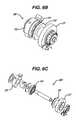
- FIG. 6Ais a perspective view of another embodiment of a deployment device
- FIG. 6Bis a perspective view of a suture tensioning element of the deployment device shown in FIG. 6A ;
- FIG. 6Cis an exploded perspective view of the suture tensioning element of FIG. 6B ;
- FIG. 7is a partially exploded perspective view of a handle assembly of the deployment device of FIG. 2 ;
- FIG. 8is a cross-sectional view of the handle assembly of FIG. 7 ;
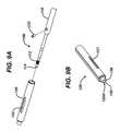
- FIG. 9Ais an exploded perspective view of a distal portion of an insertion assembly of the deployment device of FIG. 2 ;
- FIG. 9Bis a perspective view of a pusher of the insertion assembly of FIG. 9A ;
- FIG. 10is a perspective view of the insertion assembly of FIG. 1 with a suture anchor about to be attached thereto;
- FIG. 11is a perspective view of the insertion assembly and suture anchor of FIG. 10 fully assembled.
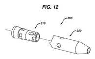
- FIG. 12is an exploded view of the suture anchor shown in FIG. 1 , having a sleeve and an insert;
- FIG. 13is a perspective view of the sleeve of the suture anchor of FIG. 12 ;
- FIG. 14is a cross-sectional view of the sleeve shown in FIG. 13 ;
- FIG. 15is a perspective view of the insert of the suture anchor of FIG. 12 ;
- FIG. 16is a cross-sectional view of the insert shown in FIG. 15 ;
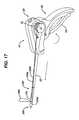
- FIG. 17is a perspective view of the suture anchor deployment device, insertion assembly, and a suture anchor of FIG. 1 having a suture coupled thereto and showing the device actuated to deploy the suture anchor.
- the present inventiongenerally provides methods and devices for attaching soft tissue to bone.
- a deployment device, insertion assembly, and suture anchorare provided.
- the insertion assemblyis coupled between the deployment device and the suture anchor to allow the deployment device to deploy the suture anchor into bone.
- FIG. 1generally illustrates one exemplary embodiment of a suture anchor deployment device 10 having an insertion assembly 100 coupled thereto and extending therefrom, and having a suture anchor 200 coupled to a distal end of the insertion assembly 100 .
- the deployment device 10which is shown in more detail in FIGS. 2 and 3 , generally includes a housing 20 having an outer shaft 22 extending distally therefrom for receiving the insertion assembly 100 , and a handle assembly 30 coupled to the housing 20 and configured to engage the insertion assembly 100 .
- the handle assembly 30 and the insertion assembly 100can move together relative to the housing 20 and outer shaft 22 to deploy a suture anchor 200 coupled to a distal end of the anchor insertion assembly 100 .
- FIG. 3illustrates the housing 20 and handle assembly 30 separated from one another.
- the handle assembly 30can include one or more slots formed in a sidewall thereof.
- FIG. 3illustrates one slot 32 formed in the sidewall thereof, however a second slot can be formed in the opposed sidewall.
- the housing 20can include one or more corresponding bores formed therein and each bore can receive a pin configured to be slidably disposed within a slot.
- FIG. 3illustrates a bore 22 a formed in a sidewall of the housing 20 and having a pin 22 b disposed therein.
- actuation of the handle assembly 30causes the housing 20 to move in a proximal direction and/or the handle assembly 30 to move in a distal direction.
- the suture anchor 200 that is coupled to the insertion assembly 100generally includes an insert 210 and a sleeve 220 that is disposable over the insert 210 .
- the sleeve 220is coupled to an inserter shaft 110 ( FIG. 10 ) of the insertion assembly 100 , and the insert 210 is slidably disposed around the inserter shaft and it abuts against a pusher 120 positioned proximally adjacent thereto and also slidably disposed around the inserter shaft.
- the pusher 120is positioned just distal of the outer shaft 22 that extends distally from the housing 20 .
- actuation of the handle assembly 30will cause the handle assembly 30 to move proximally, pulling the inserter shaft and sleeve 220 proximally.
- the outer shaft 22 of the housing 20will abut against the pusher 120 on the insertion assembly 100 , and the pusher 120 in turn will abut against the insert 210 to maintain the insert 210 in a substantially fixed position while the sleeve 220 is being pulled there over by the inserter shaft and handle assembly 30 .
- a suture coupled to the anchor 200will be engaged between the sleeve 210 and insert 210 .
- the suturecan be mated to tissue, allowing the tissue to be anchored to bone within which the suture anchor 200 is disposed.
- movement of the housing 20 and handle assembly 30is relative to each other, and that the direction of movement of each component as described and claimed herein is not intended to be limiting in any way. That is, the housing 20 can remained fixed while the handle assembly 30 moves, the handle assembly 30 can remain fixed while the housing 20 moves, or both components can move.
- the components that movecan vary depending on the configuration of the suture anchor 200 and insertion assembly 100 , as well as the method of use.
- the housing 20 of the deployment device 10can have a variety of configurations, but in the illustrated embodiment the housing 20 generally includes first and second opposed housing halves 20 a, 20 b ( FIG. 4 ) that come together to define a generally elongate, hollow body.
- the housing 20can, however, be formed from a single component, or from multiple components.
- An interior portion of the housing 20can seat a portion of the handle assembly 30 , which will be discussed in more detail below.
- the housing 20 and handle assembly 30are configured to slidably move relative to one another in a proximal-distal direction, as previously described above.
- the proximal end 20 p of the housing 20can include an opening 21 a formed therein for slidably receiving a proximal end 30 p of the handle assembly 30 .
- the opening 21 acan be formed by a cut-out formed in the proximal wall of each housing half 20 a, 20 b .
- the housing 20can also include a generally elongate, hollow outer shaft 22 that extends through an opening 21 b formed in a distal end 20 d of the housing 20 .
- the outer shaft 22is fixedly coupled to the housing 20 such that it moves in conjunction with the housing 20 .
- the particular mating locationcan vary. In the embodiment shown in FIG.
- the outer shaft 22is configured to be fixedly captured between one of the housing halves, i.e., housing half 20 b , and a clamp member 24 which is fastened to the housing half 20 b at a distal end 20 d of the housing 20 . This allows the outer shaft 22 to move with the housing 20 without interfering with sliding movement of the handle assembly 30 relative to the housing 20 .
- the outer shaft 22can also extend through a portion of the handle assembly 30 to allow a gear assembly disposed in the handle assembly 30 to engage the outer shaft 22 and slidably move the outer shaft 22 and the housing 20 relative to the handle assembly 30 .
- the gear assembly and techniques for moving the outer shaft 22 and housing 20 relative to the handle assembly 30will be described in more detail below with respect to FIGS. 7 and 8 .
- the deployment device 10can also include a suture retaining element formed or disposed thereon and configured to mate to a suture that is coupled to a suture anchor being deployed.
- the suture retaining elementcan have a variety of configurations, and it can be in the form of a clamp, fastener, pin, or other element configured to receive and retain a suture. Regardless of the configuration, in an exemplary embodiment the suture retaining element is configured such that tension applied to a suture extending between the suture retaining element and the suture anchor will be maintained at a substantially fixed tension during deployment of the suture anchor. In the embodiment shown in FIGS. 4 and 5 , this is achieved by positioning a suture retaining element on the housing 20 .
- the sutureextends between the insert of the suture anchor and the suture retaining element, and since the insert moves with the housing 20 , the suture will move with the housing 20 . As a result, the tension applied to the suture by the suture retaining element will be maintained during deployment of the suture anchor, i.e., while the sleeve is being pulled over the insert.
- the particular location of the suture retaining elementcan vary depending on the configuration of the deployment device, insertion assembly, and suture anchor.
- the suture retaining elementcan be formed or disposed on the handle assembly 30 such that is moves in coordination with the handle assembly 30 .
- FIG. 5illustrates one exemplary suture retaining element, in the form of a suture tensioning assembly 26 .
- the suture tensioning assembly 26includes a tensioning wheel 27 that is effective to receive a suture there around such that rotation of the tensioning wheel 27 increases or decreases tension applied to the suture.
- the illustrated tensioning wheel 27is in the form a cylindrical housing 27 a having a knob 27 b formed on one end thereof for grasping and rotating the tensioning wheel 27 , and having a central shaft 27 c extending therethrough.
- the central shaft 27 cis rotatably disposed through the housing 20 , and in particular through one of the housing halves, i.e., housing half 20 b . As shown in FIG.
- the deviceincludes a bushing 12 that sits within an opening 14 formed in the housing half 20 b , and that rotatably seats a portion of the tensioning wheel 27 .
- the bushing 12is mated to the housing half 20 b using a spring clip 16 disposed there around and positioned on an interior portion of the housing half 20 b .
- the suture tensioning assembly 26can also include a mechanism for maintaining the tensioning wheel 27 in a desired rotated position. As shown in FIG. 5 , the tensioning assembly 26 includes a pawl and ratchet mechanism that is coupled to the shaft 27 c of the tensioning wheel 27 .
- the ratchet mechanismis in the form of a wheel 28 a that is disposed around the shaft 27 c and that includes teeth 28 b formed there around, and a pawl 29 a that rotatably mates to the housing half 20 b , e.g., using a post 29 b formed on an interior of the housing half 20 b , and that includes an arm 29 c that is configured to engage the teeth 28 b formed around the ratchet 28 a .
- a length of suturecan be wrapped around the tensioning wheel 27 to mate the suture to the wheel 27 .
- the pawl 29 aWhen the wheel 27 is rotated in a direction that applies tension to the suture, i.e., further winds the suture around the wheel 27 , the pawl 29 a will engage the teeth 28 b on the ratchet 28 a to prevent the wheel 27 from rotating in an opposite direction, thus maintaining the wheel 27 in the desired rotated position and maintaining the tension on the suture.
- the suture tensioning assembly 26can also include a mechanism to release the tension applied to the suture, i.e., to release the pawl 29 a from engagement with the teeth 28 b on the ratchet 28 a .
- the suture tensioning assembly 26includes a cam 23 that is disposed around the ratchet 28 a and that is configured to cam the pawl 29 a out of engagement with the ratchet 28 a to allow free rotation of the tensioning wheel 27 .
- the cam 23can include a lever 23 a formed thereon and extending through a portion of the housing 20 to allow the user to effect movement of the cam 23 .
- Pivotal movement of the cam 23 relative to the housing 20can release the pawl 29 a from the ratchet 28 a .
- the cam and ratchet mechanismcan have a variety of other configurations.
- various other suture tensioning or retaining elementscan be used.
- FIGS. 6A-6Cillustrate another exemplary embodiment of a suture retaining element.
- FIG. 6Aillustrates a deployment device 10 ′ having a housing 20 ′ and a handle assembly 30 ′.
- the suture retaining element 26 ′is disposed on a back end of the housing 20 ′, and it is configured to trap a suture, rather than have the suture would there around.
- the componentsare similar to the previous embodiment however rotation of the cam 23 ′ causes a moving plate 24 ′ to slide toward a stationary plate 25 ′ to trap a suture positioned there between. Once a suture is trapped, the tensioning wheel 27 ′ can be rotated to adjust the tension applied to the suture.
- the housing 20can be slidably coupled to a handle assembly 30 that is effective, upon actuation, to deploy a suture anchor into bone.
- the handle assembly 30can have a variety of configurations, in an exemplary embodiment, as shown in FIGS. 7 and 8 , the handle assembly 30 generally includes a stationary member 32 and a trigger 34 movably coupled to the stationary member 32 .
- the stationary member 32is configured to engage an inserter shaft 110 of the insertion assembly 100 ( FIG. 10 ), and the trigger 34 is adapted to pivot toward the stationary member 32 to slide the housing 20 relative to the handle assembly 30 .
- the stationary member 32can have various shapes and sizes, but in one embodiment, as shown, it has a generally elongate hollow, rectangular housing portion 32 a and a stationary handle 32 b that extends from the housing portion 32 a and that is configured to be grasped by a user.
- the housing portion 32 ais effective to receive and mate to the inserter shaft 110 of the insertion assembly 100 ( FIG. 10 ).
- the housing portion 32 acan include an opening 33 formed in a distal end 32 d thereof for receiving a proximal end of the inserter shaft.
- the housing portion 32 acan also include a mating element formed thereon for removably engaging the inserter shaft. In the embodiment shown in FIGS.
- the housing portion 32 aincludes a locking member 36 that is disposed through an opening 37 formed in a top surface of the housing portion 32 a , and that includes a bore 36 b formed therethrough for receiving the proximal end of the inserter shaft.
- the illustrated locking member 36is in the form of a generally square or rectangular shaped member, however the locking mechanism can have various other shapes and sizes.
- the locking member 36can also be biased, e.g., using a spring disposed within the housing portion 32 a , to a locked position such that it will grasp and engage a notch formed in the proximal end of the inserter shaft to prevent the inserter shaft from being removed.
- the locking member 36can be depressed to overcome the biasing force, allowing free sliding movement of the inserter shaft relative thereto.
- a person skilled in the artwill appreciate that a variety of other techniques can be used to mate the inserter shaft to the housing portion.
- the handle assembly 30can also include a trigger 34 that is movably coupled to the stationary portion 32 a . While the type of movement of the trigger 34 can vary, in one embodiment the trigger 34 is pivotally coupled to the stationary portion 32 a such that it moves between an open position in which the trigger 34 is spaced apart from the stationary handle 32 b , as shown in FIG. 8 , and a closed position in which the trigger 34 is positioned adjacent to the stationary handle 32 b . In the illustrated embodiment, the trigger 34 is pivotally mated to the stationary portion 32 a by a pivot pin 35 .
- the trigger 34can also be effective to engage the portion of the outer shaft 22 that extends through the housing portion 32 a of the stationary member 32 such that movement of the trigger 34 between the open and closed positions is effective to move the outer shaft 22 between proximal and distal positions relative to the handle assembly 30 .
- the housing 20which is coupled to the outer shaft 22 , will move with the outer shaft 22 , thus allowing a suture anchor to be deployed, as will be discussed in more detail below.
- the handle assembly 30includes a gear mechanism disposed therein. In the embodiment shown in FIGS.
- the gear mechanismis in the form of a plurality of teeth 37 a formed on a terminal end 34 t of the trigger 34 and effective to engage corresponding teeth 37 b formed on a proximal portion of the outer shaft 22 , as will be discussed below.
- the teeth 37 a on the trigger 34will engage the teeth 37 b on the outer shaft 22 to move the outer shaft 22 in a distal direction relative to the handle assembly 30 .
- the housing 20 (not shown) of the device 10will thus move distally with the outer shaft 22 .
- the handle assembly 30 and the inserter shaft (not shown) coupled theretowill move in a proximal direction relative to the housing 20 and outer shaft 22 .
- the trigger 34can also be biased to the open position, such that a force must be applied to the trigger 34 to overcome the biasing force and move the trigger to the closed position, and such that release of the trigger 34 from the closed position will allow the trigger 34 to automatically return to the open position. While various techniques can be used to bias the trigger 34 to the open position, in one exemplary embodiment, as shown in FIGS. 7 and 8 , a spring 38 can be disposed between a proximal portion of the outer shaft 22 and a portion of the housing portion 32 a of the stationary member 32 on the handle assembly 30 .
- the handle assembly 30can include a hollow elongate member or barrel 40 disposed therein and configured to slidably seat a proximal housing 42 formed on or disposed around a proximal portion of the outer shaft 22 .
- the spring 38can be disposed within the hollow barrel 40 , and a portion of the spring 38 can be positioned around a portion of the proximal housing 42 of the outer shaft 22 .
- the teeth 37 bpreviously discussed above, can be formed on an inferior or bottom surface of the proximal housing 42 on the outer shaft 22 , and the teeth 37 b can be positioned proximal of the spring 38 .
- the spring 38will extend between the distal-most tooth of the proximal housing 42 of the outer shaft 22 and a distal end wall of the barrel 40 , as shown in FIG. 8 .
- the barrel 40can also include an elongate slot or opening formed in an inferior or bottom surface thereof for receiving the terminal end 34 t of the trigger 34 .
- the proximal housing 42 on the outer shaft 22When the trigger 34 is moved from the open position to the closed position, the proximal housing 42 on the outer shaft 22 will be moved distally, thus compressing the spring 38 between the proximal housing 42 and the distal end of the barrel 40 . As a result, when the trigger 34 is released, the spring 38 will force the proximal housing 42 on the outer shaft 22 back to the proximal position, thereby causing the teeth 37 b on the proximal housing 42 of the outer shaft 22 to engage the teeth 37 a on the trigger 34 and pivot the trigger 34 back to the open position. As further shown in FIG.
- the proximal housing 42can also include a slot 42 a formed on a superior or top surface thereof for receiving a pin 42 b extending through the housing portion 32 a of the stationary member 32 on the handle assembly 30 .
- the pin 42 b and slot 42 awill allow the proximal housing 42 on the outer shaft 22 to slidably move proximally and distally within the housing portion 32 a of the stationary member 32 , while preventing rotation thereof to keep the teeth 37 b on the proximal housing 42 in alignment with the teeth 37 a on the trigger 34 .
- a person skilled in the artwill appreciate that a variety of other techniques can be used to bias the trigger 34 to an open or a closed position, as may be desired.
- the insertion assembly 100is shown in more detail in FIGS. 9A-10 .
- the insertion assembly 100generally includes an elongate shaft, referred to herein as an inserter shaft 110 , and a pusher 120 disposed around a portion of the inserter shaft 110 .
- the inserter shaft 110includes a proximal end 110 a that is adapted to mate to the stationary portion 32 of the handle assembly 30 , as discussed above, and a distal end 110 b that is adapted to mate to one component of a suture anchor 200 , such as a sleeve 220 as will be discussed in more detail below.
- the distal end 110 b of the inserter shaft 110can include threads 112 formed around a portion thereof and adapted to engage corresponding threads formed within the sleeve 220 .
- the distal end 110 bcan also include a pointed or sharpened tip 114 adapted to facilitate penetration of the insertion assembly 100 into bone.
- the inserter shaft 110can also include a pusher 120 disposed around a portion thereof.
- the pusher 120can have various configurations, but in an exemplary embodiment it is configured to be positioned between a distal end 22 b ( FIG. 8 ) of the outer shaft 22 of the deployment device 10 and a proximal end of an anchor, such as a proximal end of an insert 210 of anchor 200 as will be discussed below.
- the pusher 120is also preferably slidably movable along a longitudinal axis of the inserter shaft 110 .
- the pusher 120will advance the insert 210 into the sleeve 220 , or alternatively to maintain the insert 210 in a fixed position as the sleeve 210 is pulled proximally there over.
- the insert 210 , pusher 120 , outer shaft 22 , and housing 20will move in coordination with one another relative to the sleeve 220 , inserter shaft 110 , and handle assembly 30 to position the insert 210 within the sleeve 220 .
- the pusher 120can be in the form of an elongate, hollow tube that is slidably disposed around a distal portion of the inserter shaft 110 .
- An elongate slot or cut-out 121can be formed in the pusher 120 , and a pin 122 can be disposed therethrough and mated to the inserter shaft 110 to allow slidable movement of the pusher 120 relative to the inserter shaft 110 while preventing rotation of the pusher 120 around the inserter shaft 110 .
- Other techniquescan optionally be used to slidably mate the pusher 120 to the inserter shaft 110 , or alternatively the pusher 120 can merely float around the inserter shaft 110 .
- the pusher 120When the pusher 120 is mated to the inserter shaft 110 , as shown in FIGS. 10 and 11 , the pusher 120 will be positioned just proximal to the insert 210 such that the distal end 120 d of the pusher 120 abuts against the insert 210 .
- the pusher 120can also optionally include an alignment mechanism for rotationally aligning the insert 210 with the pusher 120 . This can facilitate proper positioning of the insert 210 within the sleeve 220 . While various alignment techniques can be used, in one exemplary embodiment the pusher 120 and/or insert 210 can include a notch or projection formed thereon and configured to be disposed within a corresponding notch or projection formed in the other one of the pusher and/or insert. For example, FIG. 9B illustrates a cut-out or notch 125 and a projection 126 formed in the distal-most end of the pusher 120 .
- the proximal-most end of the insert 210can have a shape that complements a shape of the distal-most end of the pusher 120 , i.e., the insert 210 can include a corresponding notch 215 and projection 216 formed thereon, as shown in FIG. 16 .
- the projection 216 on the insert 210can rest within the notch 125 in the pusher 120 to rotationally align the insert 210 with the pusher 120 .
- FIG. 11illustrates the insertion assembly 100 fully assembled and mated to a suture anchor 200 .
- the suture anchor 200generally includes an outer sleeve 220 that is adapted to be disposed within a bone tunnel, and an insert 210 that is adapted to be disposed within the outer sleeve 220 .
- the sleeve 220 and insert 210are shown in more detail in FIGS. 12-16 .
- the insert 210can be configured to mate to a suture such that the suture will be locked between the insert 210 and outer sleeve 220 when the insert 210 is disposed within the outer sleeve 220 .
- the insert 210can also be configured to cause at least a portion of the outer sleeve 220 to deformably expand to lock the outer sleeve 220 within the bone tunnel.
- the outer sleeve 220 of the suture anchor 200can have a generally elongate hollow configuration with a leading distal end 220 b and a proximal trailing end 220 a .
- the distal end 220 bcan have various shapes and sizes, and it can include a bone-penetrating tip formed thereon, or alternatively it can include a bore or opening 221 formed therein as shown for allowing the tip of the inserter shaft 110 ( FIG. 10 ) to penetrate therethrough and guide the distal end 220 b of the sleeve 220 into a bone tunnel.
- FIGS. 10As further shown in FIGS.
- the distal end 220 bcan also be tapered to facilitate insertion into a bone tunnel.
- the proximal portion of the sleeve 220can also vary in shape and size, but in an exemplary embodiment the proximal portion has a generally cylindrical shape for receiving the insert 210 therein.
- the sleeve 220can also include threads 222 formed therein for mating with corresponding threads formed on the inserter shaft. While the location of the threads 222 can vary, in the illustrated embodiment the threads 222 are located just proximal to the tapered distal end 220 b of the sleeve 220 .
- the sleeve 220can also include other features that will be discussed in more detail below.
- the insert 210is shown in more detail in FIGS. 15 and 16 , and as shown the insert 210 can have a generally elongate cylindrical configuration with a distal leading end 210 b and a proximal trailing end 210 a .
- at least a portion of the insert 210has an outer diameter that is greater than an inner diameter of at least a portion of the sleeve 220 such that the insert 210 will deformably expand the sleeve 220 upon insertion of the insert 210 therein. This will allow the sleeve 220 to be embedded within the bone tunnel, thereby anchoring the suture anchor 220 in the bone tunnel.
- the insert 210can also have a flared proximal end 210 a that has an increased outer diameter as compared to the remainder of the insert 210 .
- the flared proximal end 210 acan be effective to expand the proximal trailing end 220 a of the sleeve 220 to further facilitate engagement between the sleeve 220 and the bone tunnel within which the sleeve 220 is disposed.
- the insert 210can also be hollow to allow the inserter shaft 110 ( FIG. 10 ) to extend therethrough and to mate with the sleeve 220 , which in this embodiment is positioned distal of the insert 210 .
- the insert 210is also preferably configured to mate to a suture for anchoring the suture to bone. While the insert 210 can include various features for mating with a suture, in the embodiment shown in FIGS. 15 and 16 the insert 210 includes first and second thru-bores 214 a , 214 b formed therein and configured to receive the suture therethrough.
- thru-bores 214 a , 214 bare advantageous as it allows the suture to extend into the first thru-bore 214 a and out of the second thru-bore 214 b such that a suture loop is formed and two trailing ends of the suture extend from the anchor 200 .
- the insert 210can be configured to deformably and optionally irreversibly expand at least a portion of the sleeve 220 into the bone tunnel.
- various materialscan be used to allow the sleeve 220 to expand.
- the sleeve 220 and the insert 210can each be substantially rigid and they can have the same modulus of elasticity.
- the insert 210 and the sleeve 220can also include various other features formed thereon.
- the insert 210 and the sleeve 220can include an alignment mechanism formed there between and configured to radially align the insert 210 with the sleeve 220 .
- the proximal-most end of the sleeve 220includes a plurality of protrusions 223 extending proximally therefrom.
- the protrusions 223are configured to sit within corresponding detents or bores 213 formed around a distal end of the insert 210 , as shown in FIGS. 15 and 16 .
- the insert 210 and the sleeve 220can include an engagement mechanism formed there between for locking the insert 210 and the outer sleeve 220 together to prevent accidental removal of the insert 210 from the sleeve 2210 once the anchor 200 is implanted.
- various engagement mechanismscan be used, including a friction, interference fit, mechanical interlock, etc.
- the insert 210 and the sleeve 220include a snap-lock engagement mechanism that utilizes at least one pin and at least one complementary bore for receiving the pin.
- the insert 210includes a plurality of pins 217 formed thereon and spaced around a perimeter thereof.
- the pins 217increases in height in a distal to proximal direction.
- the pins 217will extend into corresponding bores 227 formed in the sleeve 220 and spaced around a perimeter thereof, as shown in FIGS. 13 and 14 .
- the increasing height of the pins 217will allow the pins 217 to slide into the bores 227 during insertion of the insert 210 into the sleeve 220 , and will allow a trailing end or distal end of each pin 217 to extend through and engage the bores 227 to prevent back-out or removal of the insert 210 from the sleeve 220 .
- the insert 210will thus snap-lock into the sleeve 220 to provide a secure mating connection between the two components.
- the aforementioned alignment mechanisms formed between the insert 210 and the pusher 120 , and between the insert 210 and sleeve 220 ,will assist in aligning the pins 217 with the bores 227 during use.
- suture anchorcan have a variety of other configurations, and that the suture anchor described and disclosed herein is merely one exemplary embodiment of a suture anchor for use with the present invention.
- the suture anchor 200is shown mated to the insertion assembly 100 .
- the inserter shaft 110extends through the insert 210 and is threadably mated to the sleeve 220 such that the distal-most tip 114 of the inserter shaft 110 extends through the opening 221 in the distal end 220 b of the sleeve 220 .
- the insert 210is thus positioned just proximal of the sleeve 220 such that the leading distal end 210 b of the insert 210 is positioned adjacent to or in contact with the trailing proximal end 220 a of the sleeve 220 .
- the protrusions on the proximal end of the sleeve 220can seat within the detents or bores formed around the distal end of the insert 210 to radially or rotationally align the insert 210 and the sleeve 220 .
- the proximal end 210 a of the insert 210can be positioned adjacent to or in contact with the distal end 120 d of the pusher 120 such that the cut-out or notch in the proximal end of the insert 210 extends into and is aligned with the cut-out or notch in the distal end of the pusher 120 .
- FIG. 11also illustrates a suture threaded through the first and second thru-bores to form a suture loop on one side of the anchor. Two trailing ends 300 a , 300 b of the suture 300 extend proximally from the suture anchor 200 .
- the insertion assembly 100can be mated to a deployment device, such as device 10 , for deploying the suture anchor 200 into bone.
- the trailing ends 300 a , 300 b of the suture 300can be mated to the suture tensioning element 26 by winding the trailing ends 300 a , 300 b around the tensioning wheel 27 , and optionally rotating the tensioning wheel 27 to increase or decrease a tension applied to the suture 300 , as may be desired.
- the suture 300thus remains taught between the suture anchor 200 and the suture tensioning element 26 .
- the suture anchor 200can be implanted by first passing the suture through the soft tissue to be anchored, and then mating the suture to the suture anchor 200 and suture tensioning element 26 . With the soft tissue mated to the suture, the inserter shaft 110 can be forced distally through into the bone, pulling the soft tissue toward the bone. It will be appreciated that, as this occurs, the suture anchor 200 will be carried into the bone in its pre-deployed configuration, due to the threaded engagement between the sleeve 220 and the inserter shaft 110 . In fact, the distal end of the inserter shaft 110 and the tapered distal end of the sleeve 220 will cooperate with one another so as to force an opening in the bone, without any need for pre-drilling.
- the bonecan, however, optionally be pre-drilled if desired, or a mallet or other device can be used to facilitate insertion into bone.
- the suture anchor 200can be implanted by penetrating or “stabbing” the sharp distal end of the inserter shaft 110 into soft tissue (or the like) to be anchored, and positioning it against bone to which the soft tissue is to be anchored.
- the trailing ends 300 a, 300 b of the suture 300will remain attached to the suture tensioning element 26 .
- the soft tissuemay alternatively be gripped by another instrument (e.g., forceps or the like) and moved into position against the bone whereby the inserter shaft 110 can be forced distally through the tissue and into the bone.
- suture anchor 200will be carried into the bone in its pre-deployed configuration, due to the threaded engagement between the sleeve 220 and the inserter shaft 110 .
- the distal end of the inserter shaft 110 and the tapered distal end of the sleeve 220will cooperate with one another so as to force an opening in the soft tissue and the bone, without any need for pre-drilling.
- the bonecan, however, optionally be pre-drilled if desired, or a mallet or other device can be used to facilitate insertion into bone.
- the inserter shaft 110can be driven into the bone to various depths, but in an exemplary embodiment the inserter shaft 110 is driven into bone until the proximal trailing end of the insert 210 is approximately even with the outer surface of the bone. More preferably, the inserter shaft 110 can be driven deeper into bone, and the distal end 120 d of the pusher 120 can act as a stop shoulder that limits the penetration depth of the inserter shaft 110 . In other embodiments, markings (not shown) may be placed on the outer surface of the inserter shaft 110 so that proper depth penetration can be achieved.
- the trigger 34 on the deployment device 10can be moved from the open position, shown in FIG. 1 , to the closed position, shown in FIG. 17 by squeezing the trigger 34 .
- the handle assembly 30will slide proximally relative to the housing 20 , thus pulling the inserter shaft 110 proximally relative to the outer shaft 22 .
- the housing 20 , outer shaft 22 , pusher 120 , and insert 210will remain in a substantially fixed position as the handle assembly 30 , inserter shaft 110 , and sleeve 220 move proximally.
- the suture 300 extending between the anchor 200 and the suture tensioning element 26will remain fixed so as to not interfere with the tension applied to the suture 300 . The tension thus remains unchanged.
- the interference fit between the sleeve 220 and the insert 210will trap and lock the suture 300 there between, and the insert 210 will be locked within the sleeve 220 using the snap-fit engagement previously discussed.
- the insert 210can also cause at least a portion of the sleeve 220 to expand, e.g., the proximal portion, causing the sleeve 220 to engage the bone tunnel.
- the inserter shaft 110can be unscrewed from the sleeve 220 and removed, leaving the suture anchor 200 behind.
- the trailing ends 300 a , 300 b of the suture 300 that extend from the suture anchor 200 and through the soft tissuecan be knotted, e.g., using a knotting element, or otherwise fastened to secure the soft tissue to the bone.
- the insertcan optionally be advanced into the sleeve as the sleeve remains in a substantially fixed position.
- the tension applied to the suturein such case will still remain fixed, as the suture and tensioning element attached thereto will move with the insert.
- the sleevecan be positioned proximal of the insert, and the insert can be retracted into the sleeve or the sleeve can be pushed over the insert.
Landscapes
- Health & Medical Sciences (AREA)
- Surgery (AREA)
- Life Sciences & Earth Sciences (AREA)
- Biomedical Technology (AREA)
- Nuclear Medicine, Radiotherapy & Molecular Imaging (AREA)
- Engineering & Computer Science (AREA)
- Heart & Thoracic Surgery (AREA)
- Medical Informatics (AREA)
- Molecular Biology (AREA)
- Animal Behavior & Ethology (AREA)
- General Health & Medical Sciences (AREA)
- Public Health (AREA)
- Veterinary Medicine (AREA)
- Rheumatology (AREA)
- Surgical Instruments (AREA)
Abstract
Description
Claims (22)
Priority Applications (9)
| Application Number | Priority Date | Filing Date | Title |
|---|---|---|---|
| US11/462,416US9750492B2 (en) | 2006-08-04 | 2006-08-04 | Suture anchor system with tension relief mechanism |
| AU2007203593AAU2007203593B2 (en) | 2006-08-04 | 2007-08-01 | Suture anchor system with tension relief mechanism |
| CA2596051ACA2596051C (en) | 2006-08-04 | 2007-08-03 | Suture anchor system with tension relief mechanism |
| EP07253061AEP1884198B1 (en) | 2006-08-04 | 2007-08-03 | Suture anchor system with tension relief mechanism |
| DE602007005189TDE602007005189D1 (en) | 2006-08-04 | 2007-08-03 | tion |
| EP10075058.7AEP2189119B1 (en) | 2006-08-04 | 2007-08-03 | Suture anchor system with tension relief mechanism |
| JP2007203520AJP5329058B2 (en) | 2006-08-04 | 2007-08-03 | Suture fastening system with strain relief |
| CA2709849ACA2709849C (en) | 2006-08-04 | 2007-08-03 | Suture anchor system with tension relief mechanism |
| US15/691,861US10813633B2 (en) | 2006-08-04 | 2017-08-31 | Suture anchor system with tension relief mechanism |
Applications Claiming Priority (1)
| Application Number | Priority Date | Filing Date | Title |
|---|---|---|---|
| US11/462,416US9750492B2 (en) | 2006-08-04 | 2006-08-04 | Suture anchor system with tension relief mechanism |
Related Child Applications (1)
| Application Number | Title | Priority Date | Filing Date |
|---|---|---|---|
| US15/691,861DivisionUS10813633B2 (en) | 2006-08-04 | 2017-08-31 | Suture anchor system with tension relief mechanism |
Publications (2)
| Publication Number | Publication Date |
|---|---|
| US20080033460A1 US20080033460A1 (en) | 2008-02-07 |
| US9750492B2true US9750492B2 (en) | 2017-09-05 |
Family
ID=38685978
Family Applications (2)
| Application Number | Title | Priority Date | Filing Date |
|---|---|---|---|
| US11/462,416Active2030-08-21US9750492B2 (en) | 2006-08-04 | 2006-08-04 | Suture anchor system with tension relief mechanism |
| US15/691,861Active2027-10-25US10813633B2 (en) | 2006-08-04 | 2017-08-31 | Suture anchor system with tension relief mechanism |
Family Applications After (1)
| Application Number | Title | Priority Date | Filing Date |
|---|---|---|---|
| US15/691,861Active2027-10-25US10813633B2 (en) | 2006-08-04 | 2017-08-31 | Suture anchor system with tension relief mechanism |
Country Status (6)
| Country | Link |
|---|---|
| US (2) | US9750492B2 (en) |
| EP (2) | EP2189119B1 (en) |
| JP (1) | JP5329058B2 (en) |
| AU (1) | AU2007203593B2 (en) |
| CA (2) | CA2709849C (en) |
| DE (1) | DE602007005189D1 (en) |
Cited By (16)
| Publication number | Priority date | Publication date | Assignee | Title |
|---|---|---|---|---|
| US10105132B2 (en) | 2005-05-20 | 2018-10-23 | Neotract, Inc. | Devices, systems and methods for treating benign prostatic hyperplasia and other conditions |
| US10130353B2 (en) | 2012-06-29 | 2018-11-20 | Neotract, Inc. | Flexible system for delivering an anchor |
| US10143461B2 (en) | 2005-05-20 | 2018-12-04 | Neotract, Inc. | Devices, systems and methods for retracting, lifting, compressing, supporting or repositioning tissues or anatomical structures |
| US10195014B2 (en) | 2005-05-20 | 2019-02-05 | Neotract, Inc. | Devices, systems and methods for treating benign prostatic hyperplasia and other conditions |
| US10265061B2 (en) | 2005-05-20 | 2019-04-23 | Neotract, Inc. | Latching anchor device |
| US10292801B2 (en) | 2012-03-29 | 2019-05-21 | Neotract, Inc. | System for delivering anchors for treating incontinence |
| US10299780B2 (en) | 2005-05-20 | 2019-05-28 | Neotract, Inc. | Apparatus and method for manipulating or retracting tissue and anatomical structure |
| US10426509B2 (en) | 2005-05-20 | 2019-10-01 | Neotract, Inc. | Median lobe destruction apparatus and method |
| US10492792B2 (en) | 2005-05-20 | 2019-12-03 | Neotract, Inc. | Devices, systems and methods for treating benign prostatic hyperplasia and other conditions |
| US20200146674A1 (en)* | 2007-02-13 | 2020-05-14 | P Tech, Llc | Tissue fixation system and method |
| US10925587B2 (en) | 2005-05-20 | 2021-02-23 | Neotract, Inc. | Anchor delivery system |
| US20220015753A1 (en)* | 2018-12-18 | 2022-01-20 | Conmed Corporation | Self-drilling anchor inserter |
| US11337689B2 (en)* | 2020-08-31 | 2022-05-24 | Yoon Ho CHUNG | Benign prostatic hyperplasia treatment device |
| US20220249219A1 (en)* | 2020-08-31 | 2022-08-11 | Yoon Ho CHUNG | Benign prostatic hyperplasia treatment device |
| US11672520B2 (en) | 2017-12-23 | 2023-06-13 | Teleflex Life Sciences Limited | Expandable tissue engagement apparatus and method |
| US12440301B2 (en) | 2019-10-30 | 2025-10-14 | Teleflex Life Sciences Llc | System for delivery of a fiducial marker |
Families Citing this family (96)
| Publication number | Priority date | Publication date | Assignee | Title |
|---|---|---|---|---|
| US6319252B1 (en)* | 1999-07-23 | 2001-11-20 | Mcdevitt Dennis | System and method for attaching soft tissue to bone |
| US6527794B1 (en) | 1999-08-10 | 2003-03-04 | Ethicon, Inc. | Self-locking suture anchor |
| US6733506B1 (en)* | 2000-11-16 | 2004-05-11 | Ethicon, Inc. | Apparatus and method for attaching soft tissue to bone |
| CA2477220C (en) | 2002-03-14 | 2007-11-06 | Jeffrey E. Yeung | Suture anchor and approximating device |
| DE102005015687A1 (en)* | 2005-04-06 | 2006-10-12 | Karl Storz Gmbh & Co. Kg | Apparatus for delivering surgical sutures to a needle |
| US8491606B2 (en) | 2005-05-20 | 2013-07-23 | Neotract, Inc. | Median lobe retraction apparatus and method |
| US8425535B2 (en) | 2005-05-20 | 2013-04-23 | Neotract, Inc. | Multi-actuating trigger anchor delivery system |
| US8157815B2 (en) | 2005-05-20 | 2012-04-17 | Neotract, Inc. | Integrated handle assembly for anchor delivery system |
| US8945152B2 (en) | 2005-05-20 | 2015-02-03 | Neotract, Inc. | Multi-actuating trigger anchor delivery system |
| US9504461B2 (en) | 2005-05-20 | 2016-11-29 | Neotract, Inc. | Anchor delivery system |
| US9149266B2 (en) | 2005-05-20 | 2015-10-06 | Neotract, Inc. | Deforming anchor device |
| US8834492B2 (en) | 2005-05-20 | 2014-09-16 | Neotract, Inc. | Continuous indentation lateral lobe apparatus and method |
| US8333776B2 (en) | 2005-05-20 | 2012-12-18 | Neotract, Inc. | Anchor delivery system |
| US7909836B2 (en) | 2005-05-20 | 2011-03-22 | Neotract, Inc. | Multi-actuating trigger anchor delivery system |
| US8216254B2 (en) | 2005-05-20 | 2012-07-10 | Neotract, Inc. | Anchor delivery system with replaceable cartridge |
| US7896891B2 (en) | 2005-05-20 | 2011-03-01 | Neotract, Inc. | Apparatus and method for manipulating or retracting tissue and anatomical structure |
| US8394113B2 (en) | 2005-05-20 | 2013-03-12 | Neotract, Inc. | Coiled anchor device |
| US8529584B2 (en) | 2005-05-20 | 2013-09-10 | Neotract, Inc. | Median lobe band implant apparatus and method |
| US9364212B2 (en) | 2005-05-20 | 2016-06-14 | Neotract, Inc. | Suture anchoring devices and methods for use |
| US7976554B2 (en) | 2006-04-19 | 2011-07-12 | Vibrynt, Inc. | Devices, tools and methods for performing minimally invasive abdominal surgical procedures |
| US8556925B2 (en) | 2007-10-11 | 2013-10-15 | Vibrynt, Inc. | Devices and methods for treatment of obesity |
| US8202295B2 (en) | 2006-07-20 | 2012-06-19 | Kaplan Lee D | Surgical instruments |
| CA2657619A1 (en)* | 2006-07-20 | 2008-01-24 | Lee D. Kaplan | Surgical instruments |
| US9750492B2 (en) | 2006-08-04 | 2017-09-05 | Depuy Mitek, Llc | Suture anchor system with tension relief mechanism |
| US9788825B2 (en) | 2006-08-04 | 2017-10-17 | Depuy Mitek, Llc | Suture anchor with relief mechanism |
| US8758366B2 (en) | 2007-07-09 | 2014-06-24 | Neotract, Inc. | Multi-actuating trigger anchor delivery system |
| AU2008316604B2 (en) | 2007-10-25 | 2014-11-06 | Smith & Nephew, Inc. | Anchor assembly |
| CA2702952C (en) | 2007-10-27 | 2017-01-03 | Parcus Medical, Llc | Suture anchor |
| US8974494B2 (en)* | 2008-07-17 | 2015-03-10 | Smith & Nephew, Inc. | Surgical devices |
| WO2010014825A1 (en) | 2008-07-30 | 2010-02-04 | Neotract, Inc. | Slotted anchor device |
| BRPI0920406A2 (en) | 2008-10-10 | 2019-09-24 | Guided Delivery Systems Inc | termination devices and related methods. |
| JP2012505049A (en)* | 2008-10-10 | 2012-03-01 | ガイデッド デリバリー システムズ, インコーポレイテッド | Tether tensioning device and related methods |
| US10517719B2 (en) | 2008-12-22 | 2019-12-31 | Valtech Cardio, Ltd. | Implantation of repair devices in the heart |
| US9968452B2 (en) | 2009-05-04 | 2018-05-15 | Valtech Cardio, Ltd. | Annuloplasty ring delivery cathethers |
| US11246585B2 (en) | 2009-07-17 | 2022-02-15 | Stryker Puerto Rico Limited | Method and apparatus for attaching tissue to bone, including the provision and use of a novel knotless suture anchor system |
| US9149268B2 (en) | 2009-07-17 | 2015-10-06 | Pivot Medical, Inc. | Method and apparatus for attaching tissue to bone, including the provision and use of a novel knotless suture anchor system |
| US9179905B2 (en) | 2009-07-17 | 2015-11-10 | Pivot Medical, Inc. | Method and apparatus for re-attaching the labrum to the acetabulum, including the provision and use of a novel suture anchor system |
| US10238379B2 (en) | 2009-07-17 | 2019-03-26 | Pivot Medical, Inc. | Method and apparatus for attaching tissue to bone, including the provision and use of a novel knotless suture anchor system |
| US10426456B2 (en) | 2009-07-17 | 2019-10-01 | Pivot Medical, Inc. | Method and apparatus for re-attaching the labrum to the acetabulum, including the provision and use of a novel suture anchor system |
| US11197663B2 (en) | 2009-07-17 | 2021-12-14 | Stryker Puerto Rico Limited | Method and apparatus for attaching tissue to bone, including the provision and use of a novel knotless suture anchor system |
| US12232718B2 (en) | 2009-07-17 | 2025-02-25 | Stryker Puerto Rico Limited | Method and apparatus for attaching tissue to bone, including the provision and use of a novel knotless suture anchor system |
| US10136884B2 (en) | 2009-07-17 | 2018-11-27 | Pivot Medical, Inc. | Method and apparatus for attaching tissue to bone, including the provision and use of a novel knotless suture anchor system, including a retractable sheath |
| JP2013510659A (en) | 2009-11-10 | 2013-03-28 | スミス アンド ネフュー インコーポレーテッド | Tissue repair device |
| US8460340B2 (en)* | 2010-08-30 | 2013-06-11 | Depuy Mitek, Llc | Knotless suture anchor |
| US8435264B2 (en) | 2010-08-30 | 2013-05-07 | Depuy Mitek, Llc | Knotless suture anchor and driver |
| US8679159B2 (en)* | 2010-08-30 | 2014-03-25 | Depuy Mitek, Llc | Anchor driver with suture clutch |
| US8469998B2 (en) | 2010-08-30 | 2013-06-25 | Depuy Mitek, Llc | Knotless suture anchor |
| US9161749B2 (en) | 2011-04-14 | 2015-10-20 | Neotract, Inc. | Method and apparatus for treating sexual dysfunction |
| CN103917183A (en) | 2011-06-29 | 2014-07-09 | 皮沃特医疗公司 | Method and apparatus for re-attaching the labrum to the acetabulum, including the provision and use of a novel suture anchor system |
| US9421009B1 (en) | 2011-09-27 | 2016-08-23 | A. Jamie Riley | Suture delivery system |
| US20130085528A1 (en) | 2011-09-30 | 2013-04-04 | Depuy Mitek, Inc. | Knotless suture anchor |
| US8858623B2 (en) | 2011-11-04 | 2014-10-14 | Valtech Cardio, Ltd. | Implant having multiple rotational assemblies |
| US9138220B2 (en) | 2011-12-19 | 2015-09-22 | Medos International Sarl | Knotless suture anchor |
| US8382775B1 (en) | 2012-01-08 | 2013-02-26 | Vibrynt, Inc. | Methods, instruments and devices for extragastric reduction of stomach volume |
| US9314362B2 (en) | 2012-01-08 | 2016-04-19 | Vibrynt, Inc. | Methods, instruments and devices for extragastric reduction of stomach volume |
| EP2911593B1 (en) | 2012-10-23 | 2020-03-25 | Valtech Cardio, Ltd. | Percutaneous tissue anchor techniques |
| WO2014064694A2 (en) | 2012-10-23 | 2014-05-01 | Valtech Cardio, Ltd. | Controlled steering functionality for implant-delivery tool |
| DE102012220602A1 (en)* | 2012-11-13 | 2014-06-12 | Mathys Ag Bettlach | Surgical thread tensioning device |
| KR101356009B1 (en)* | 2012-12-17 | 2014-01-29 | ㈜ 이트리온 | Tension controllable apparatus for the fixation of ligament screw |
| EP2961351B1 (en) | 2013-02-26 | 2018-11-28 | Mitralign, Inc. | Devices for percutaneous tricuspid valve repair |
| US10449333B2 (en) | 2013-03-14 | 2019-10-22 | Valtech Cardio, Ltd. | Guidewire feeder |
| EP2967535A4 (en) | 2013-03-15 | 2016-11-16 | Mark Brunsvold | Suture anchor |
| US9451954B2 (en) | 2013-03-15 | 2016-09-27 | Howmedica Osteonics Corp. | Ratcheting inserter device and suture anchor arrangement |
| US10070857B2 (en) | 2013-08-31 | 2018-09-11 | Mitralign, Inc. | Devices and methods for locating and implanting tissue anchors at mitral valve commissure |
| WO2015059699A2 (en) | 2013-10-23 | 2015-04-30 | Valtech Cardio, Ltd. | Anchor magazine |
| AU2014362199B2 (en)* | 2013-12-12 | 2019-07-11 | Stryker Puerto Rico Limited | Method and apparatus for attaching tissue to bone, including the provision and use of a novel knotless suture anchor system |
| US10098628B2 (en) | 2014-07-22 | 2018-10-16 | Cook Medical Technologies Llc | Anchor deployment system, device, and method of treatment |
| WO2016028978A1 (en)* | 2014-08-20 | 2016-02-25 | Yale University | Assemblies and methodologies for the repair of hernias |
| CN107847320B (en) | 2015-04-30 | 2020-03-17 | 瓦尔泰克卡迪欧有限公司 | Valvuloplasty techniques |
| CA2895713C (en) | 2015-05-27 | 2017-12-19 | Lewis Pearce BRANTHOVER | Suture anchor management |
| CN106456152A (en) | 2015-05-28 | 2017-02-22 | 瑞特医疗技术公司 | Suture anchor management |
| CN106714700A (en)* | 2015-05-29 | 2017-05-24 | 瑞特医疗技术公司 | Suture anchor management |
| US10085756B2 (en) | 2015-07-24 | 2018-10-02 | Covidien Lp | Anvil assembly and anvil assembly delivery system |
| US12383253B2 (en)* | 2015-08-04 | 2025-08-12 | Crossroads Extremity Systems, Llc | Suture anchor |
| US9924935B2 (en) | 2015-10-23 | 2018-03-27 | Smith & Nephew, Inc. | Suture anchor assembly with slip fit tip |
| KR20230104750A (en)* | 2015-12-16 | 2023-07-10 | 콘메드 코포레이션 | Knotless suture anchor and deployment device |
| US12207812B2 (en) | 2016-05-18 | 2025-01-28 | Orthonoble Inc. | Disposable instrument nosepieces for repairing soft tissue to bone coupling |
| US12369932B2 (en) | 2016-09-07 | 2025-07-29 | Daniel Ezra Walzman | Methods and devices to ameliorate vascular obstruction |
| US11439492B2 (en) | 2016-09-07 | 2022-09-13 | Daniel Ezra Walzman | Lasso filter tipped microcatheter for simultaneous rotating separator, irrigator for thrombectomy and method for use |
| US12138149B2 (en) | 2016-09-07 | 2024-11-12 | Daniel Ezra Walzman | Endovascular devices and methods with filtering elements |
| US11877752B2 (en) | 2016-09-07 | 2024-01-23 | Daniel Ezra Walzman | Filterless aspiration, irrigating, macerating, rotating microcatheter and method of use |
| US11135062B2 (en) | 2017-11-20 | 2021-10-05 | Valtech Cardio Ltd. | Cinching of dilated heart muscle |
| WO2019233278A1 (en)* | 2018-06-08 | 2019-12-12 | 杭州德晋医疗科技有限公司 | Adjustable suture locking device |
| EP3934546B1 (en)* | 2019-03-06 | 2025-08-27 | Speed Clip Solutions, LLC | Suture tensioning and securement device and system |
| SG11202112651QA (en) | 2019-05-29 | 2021-12-30 | Valtech Cardio Ltd | Tissue anchor handling systems and methods |
| US11672524B2 (en) | 2019-07-15 | 2023-06-13 | Ancora Heart, Inc. | Devices and methods for tether cutting |
| JP2022546160A (en) | 2019-08-30 | 2022-11-04 | エドワーズ ライフサイエンシーズ イノベーション (イスラエル) リミテッド | Anchor channel tip |
| EP4034042A1 (en) | 2019-09-25 | 2022-08-03 | Cardiac Implants LLC | Cardiac valve annulus reduction system |
| CN111803155B (en)* | 2020-06-24 | 2025-07-04 | 北京德益达美医疗科技有限公司 | Suture handles and soft tissue staplers |
| CN114286646B (en) | 2020-08-03 | 2024-03-08 | 泰利福生命科学有限公司 | Handle and cassette system for medical intervention |
| US12156647B2 (en)* | 2020-09-15 | 2024-12-03 | Smith & Nephew, Inc. | Joint repair augmentation |
| EP4280973A4 (en)* | 2021-01-22 | 2025-02-12 | Paragon 28, Inc. | SOFT TISSUE IMPLANTS, INSTRUMENTATION AND METHODS |
| US12137894B2 (en)* | 2021-12-30 | 2024-11-12 | Medos International Sarl | Knotless anchor inserter tool extraction |
| USD1019945S1 (en) | 2021-12-30 | 2024-03-26 | Medos International Sarl | Suture anchor insertion device |
| US20230338019A1 (en)* | 2022-04-20 | 2023-10-26 | Arthrex, Inc. | Suture tensioner and methods of tensioning |
| CN115670548B (en)* | 2022-11-10 | 2023-07-21 | 尤尼泰科(重庆)医疗科技有限公司 | Pre-tensioned full-suture anchor inserter |
Citations (247)
| Publication number | Priority date | Publication date | Assignee | Title |
|---|---|---|---|---|
| US2381050A (en) | 1943-12-04 | 1945-08-07 | Mervyn G Hardinge | Fracture reducing device |
| US3035583A (en) | 1959-05-27 | 1962-05-22 | Hirsch Winfred | Conductive sutures |
| US3036482A (en) | 1960-09-02 | 1962-05-29 | Kenworthy Kenneth | Axial-impact type hand tool |
| US3103926A (en) | 1961-01-13 | 1963-09-17 | Orthopaedic Specialties Corp | Surgical bone pin |
| US3135414A (en) | 1962-06-18 | 1964-06-02 | Lee Co | Plug |
| US3525365A (en) | 1966-10-17 | 1970-08-25 | Pneumo Dynamics Corp | Expansion plug |
| US3566739A (en) | 1969-02-07 | 1971-03-02 | Charles S Lebar | Anchoring device |
| US3708883A (en) | 1971-01-04 | 1973-01-09 | S Flander | Dental implant and method for using the same |
| US3760802A (en) | 1971-02-26 | 1973-09-25 | Fischer Artur | Supporting device for fractured tubular bones |
| US3842824A (en) | 1973-03-19 | 1974-10-22 | A Neufeld | Notched surgical pin and breaking tool therefor |
| US4013071A (en) | 1974-11-11 | 1977-03-22 | Lior Rosenberg | Fasteners particularly useful as orthopedic screws |
| FR2346591A1 (en) | 1976-03-30 | 1977-10-28 | Schafers Heinrich | ANCHOR AND ANCHOR METHOD FOR THIS EFFECT |
| US4091806A (en) | 1976-01-13 | 1978-05-30 | Jacob Aginsky | Intramedullary compression nail for the treatment of bone fractures |
| US4140111A (en) | 1977-09-06 | 1979-02-20 | Morrill William E | Hand tool for inserting bone fracture pins |
| GB2084468A (en) | 1980-09-25 | 1982-04-15 | South African Inventions | Surgical implant |
| EP0058744A1 (en) | 1981-02-18 | 1982-09-01 | GebràDer Sulzer Aktiengesellschaft | Expandable plug for the medullary canal of a bone |
| US4408938A (en) | 1981-08-24 | 1983-10-11 | Maguire James V | Expansion sleeve |
| US4475856A (en) | 1979-12-21 | 1984-10-09 | Telefonaktiebolaget L M Ericsson | Expansion screw with an expansion sleeve having an outer cylindrical surface and regions of greater and lesser wall thickness |
| EP0124489A1 (en) | 1983-03-09 | 1984-11-07 | TAC RIVETING SYSTEM di Oggionni Pier Giorgio & C. s.a.s. | Wall dowel |
| US4484570A (en) | 1980-05-28 | 1984-11-27 | Synthes Ltd. | Device comprising an implant and screws for fastening said implant to a bone, and a device for connecting two separated pieces of bone |
| US4492226A (en) | 1979-10-10 | 1985-01-08 | Vsesojuzny Nauchno-Issledovatelsky I Ispytatelny Institut Meditsinskoi Tekhniki | Device for uniting bone fragments |
| US4498468A (en) | 1981-05-11 | 1985-02-12 | Hansson Lars Ingvar | Bone fixation driving instrument |
| US4506670A (en) | 1983-03-30 | 1985-03-26 | United States Surgical Corporation | Two-part surgical fastener applying apparatus with frangible member |
| DE3406961A1 (en) | 1984-02-25 | 1985-09-05 | Stiefel Laboratorium GmbH, 6050 Offenbach | Skin punch |
| DE8520206U1 (en) | 1985-07-12 | 1985-12-19 | Fischer, Artur, Dr.H.C., 7244 Waldachtal | Fixing element for osteosynthesis |
| US4632100A (en) | 1985-08-29 | 1986-12-30 | Marlowe E. Goble | Suture anchor assembly |
| EP0232049A1 (en) | 1986-01-24 | 1987-08-12 | Pfizer Hospital Products Group, Inc. | Fixation device for a ligament or tendon prosthesis |
| EP0241240A2 (en) | 1986-04-07 | 1987-10-14 | E. Marlowe Goble | Suture anchor apparatus |
| US4711232A (en) | 1985-07-12 | 1987-12-08 | Artur Fischer | Bone fastener and method of installing same |
| US4716893A (en) | 1985-03-11 | 1988-01-05 | Artur Fischer | Bone fastener |
| EP0251583A2 (en) | 1986-06-23 | 1988-01-07 | Howmedica Inc. | Modular femoral fixation system |
| EP0260970A2 (en) | 1986-09-19 | 1988-03-23 | IMPERIAL COLLEGE OF SCIENCE & TECHNOLOGY | Improvements in and relating to artificial ligaments |
| US4741330A (en) | 1983-05-19 | 1988-05-03 | Hayhurst John O | Method and apparatus for anchoring and manipulating cartilage |
| EP0270704A1 (en) | 1986-12-12 | 1988-06-15 | Aesculap Ag | Anchoring element for fastening an osteosynthesis plate to a bone |
| US4760843A (en) | 1985-07-12 | 1988-08-02 | Artur Fischer | Connector for fractured bones |
| WO1988009157A1 (en) | 1987-05-18 | 1988-12-01 | Mitek Surgical Products, Inc. | Suture anchor |
| US4790304A (en) | 1984-01-20 | 1988-12-13 | Lior Rosenberg | Self-locking pin device particularly useful for internally fixing bone fractures |
| US4797044A (en) | 1985-10-31 | 1989-01-10 | Velasco Vincente S | Improvements introduced in the anchoring systems by means of threaded bolts |
| WO1989001767A1 (en) | 1987-09-02 | 1989-03-09 | Russell Warren | Surgical fastener |
| FR2622430A1 (en) | 1987-10-30 | 1989-05-05 | Laboureau Jacques | Surgical staple for immediate fixation of artificial ligaments and accessory instrument for its implantation in the bone |
| US4834752A (en) | 1986-03-17 | 1989-05-30 | Minnesota Mining And Manufacturing | Tissue augmentation device and method of repairing a ligament or tendon |
| US4870957A (en) | 1988-12-27 | 1989-10-03 | Marlowe Goble E | Ligament anchor system |
| US4871289A (en) | 1988-11-25 | 1989-10-03 | Olympic Manufacturing Group, Inc. | Expansion fastener |
| US4873976A (en) | 1984-02-28 | 1989-10-17 | Schreiber Saul N | Surgical fasteners and method |
| EP0340159A1 (en) | 1988-04-27 | 1989-11-02 | GebràDer Sulzer Aktiengesellschaft | Dowel pin for cementless bone implants |
| US4924865A (en) | 1986-05-20 | 1990-05-15 | Concept, Inc. | Repair tack for bodily tissue |
| US4927421A (en) | 1989-05-15 | 1990-05-22 | Marlowe Goble E | Process of endosteal fixation of a ligament |
| US4940467A (en) | 1988-02-03 | 1990-07-10 | Tronzo Raymond G | Variable length fixation device |
| US4944742A (en) | 1988-06-06 | 1990-07-31 | Johnson & Johnson Orthopaedics, Inc. | Bone pin |
| EP0390613A1 (en) | 1989-03-31 | 1990-10-03 | United States Surgical Corporation | Absorbable surgical fastener with bone penetrating elements |
| EP0409364A2 (en) | 1989-07-13 | 1991-01-23 | ARTOS Medizinische Produkte GmbH | Junction element for osteosynthesis |
| US4988351A (en) | 1989-01-06 | 1991-01-29 | Concept, Inc. | Washer for use with cancellous screw for attaching soft tissue to bone |
| US5013316A (en) | 1990-03-26 | 1991-05-07 | Marlowe Goble E | Soft tissue anchor system |
| US5037422A (en) | 1990-07-02 | 1991-08-06 | Acufex Microsurgical, Inc. | Bone anchor and method of anchoring a suture to a bone |
| US5059206A (en) | 1989-04-12 | 1991-10-22 | Winters Thomas F | Method and apparatus for repairing a tear in a knee meniscus |
| US5078718A (en) | 1990-04-17 | 1992-01-07 | Origin Medsystems, Inc. | Multi-part method and apparatus for removing pre-placed prosthetic joints and preparing for their replacement |
| US5084050A (en) | 1984-12-14 | 1992-01-28 | Klaus Draenert | Implant for bone reinforcement and for anchoring bone screws, implants and implant parts |
| WO1992004874A1 (en) | 1990-09-25 | 1992-04-02 | Nicholson Associates, Inc. | Bone fastener |
| GB2248778A (en) | 1990-10-09 | 1992-04-22 | Biomet Ltd | Ligament fixator |
| US5116337A (en) | 1991-06-27 | 1992-05-26 | Johnson Lanny L | Fixation screw and method for ligament reconstruction |
| US5122132A (en) | 1991-08-01 | 1992-06-16 | Bremer Medical, Inc. | Skull pin with enhanced shear resistance |
| US5141520A (en) | 1991-10-29 | 1992-08-25 | Marlowe Goble E | Harpoon suture anchor |
| US5141373A (en) | 1990-08-15 | 1992-08-25 | Kendall James W | Flush breaking interference fit blind fastener |
| US5152763A (en) | 1991-04-02 | 1992-10-06 | Johnson Lanny L | Method for grafting bone |
| US5152735A (en) | 1990-02-15 | 1992-10-06 | Podd Jr Victor I | Bracing system for a liner for a cargo container |
| US5154189A (en) | 1988-06-03 | 1992-10-13 | Oberlander Michael A | Method for repairing a torn meniscus |
| US5169400A (en) | 1988-04-02 | 1992-12-08 | Aesculap Ag | Bone screw |
| US5176682A (en) | 1992-06-01 | 1993-01-05 | Chow James C Y | Surgical implement |
| US5203784A (en) | 1989-09-08 | 1993-04-20 | Linvatec Corporation | Bioabsorbable tack for joining bodily tissue and apparatus for deploying same |
| FR2682867A1 (en) | 1991-10-29 | 1993-04-30 | Nouaille Jean Marc | METHOD AND DEVICE FOR LOCKING A WIRE IN CORE SURGERY. |
| US5207679A (en) | 1991-09-26 | 1993-05-04 | Mitek Surgical Products, Inc. | Suture anchor and installation tool |
| US5207579A (en) | 1991-05-22 | 1993-05-04 | The United States Of America As Represented By The Secretary Of The Army | Antipersonnel training mine |
| US5209753A (en) | 1989-11-03 | 1993-05-11 | Lutz Biedermann | Bone screw |
| USRE34293E (en) | 1987-02-17 | 1993-06-22 | Globe Marlowe E | Ligament attachment method and apparatus |
| US5224946A (en) | 1990-07-02 | 1993-07-06 | American Cyanamid Company | Bone anchor and method of anchoring a suture to a bone |
| US5236445A (en) | 1990-07-02 | 1993-08-17 | American Cyanamid Company | Expandable bone anchor and method of anchoring a suture to a bone |
| US5244946A (en) | 1990-02-02 | 1993-09-14 | The Dow Chemical Company | Styrenic copolymer/polyacetal/thermoplastic polyurethane or elastomeric copolyester blend compositions |
| US5248231A (en) | 1991-10-09 | 1993-09-28 | Avdel System Limited | Self-plugging blind rivet |
| US5258015A (en) | 1991-05-03 | 1993-11-02 | American Cyanamid Company | Locking filament caps |
| US5257637A (en) | 1991-03-22 | 1993-11-02 | El Gazayerli Mohamed M | Method for suture knot placement and tying |
| US5261914A (en) | 1987-09-02 | 1993-11-16 | Russell Warren | Surgical fastener |
| US5269783A (en) | 1991-05-13 | 1993-12-14 | United States Surgical Corporation | Device and method for repairing torn tissue |
| EP0574707A1 (en) | 1992-06-15 | 1993-12-22 | United States Surgical Corporation | Suture anchoring device and method |
| EP0589306A2 (en) | 1992-09-21 | 1994-03-30 | United States Surgical Corporation | Device for applying a meniscal staple |
| US5314427A (en) | 1992-10-13 | 1994-05-24 | Marlowe Goble E | Channel ligament clamp |
| US5324308A (en) | 1993-10-28 | 1994-06-28 | Javin Pierce | Suture anchor |
| US5326205A (en) | 1992-05-27 | 1994-07-05 | Anspach Jr William E | Expandable rivet assembly |
| CA2153594A1 (en) | 1993-01-15 | 1994-07-21 | E. Marlowe Goble | Pin for securing a replacement ligament to a bone |
| EP0611557A2 (en) | 1993-02-17 | 1994-08-24 | SMITH & NEPHEW DYONICS INC | Surgical implant & surgical kit |
| US5352229A (en) | 1993-05-12 | 1994-10-04 | Marlowe Goble E | Arbor press staple and washer and method for its use |
| US5354298A (en) | 1991-03-22 | 1994-10-11 | United States Surgical Corporation | Suture anchor installation system |
| US5370662A (en) | 1993-06-23 | 1994-12-06 | Kevin R. Stone | Suture anchor assembly |
| WO1995002998A1 (en) | 1993-07-26 | 1995-02-02 | Innovasive Devices, Inc. | Suture grasping device |
| US5411523A (en) | 1994-04-11 | 1995-05-02 | Mitek Surgical Products, Inc. | Suture anchor and driver combination |
| US5417712A (en) | 1994-02-17 | 1995-05-23 | Mitek Surgical Products, Inc. | Bone anchor |
| US5423860A (en) | 1993-05-28 | 1995-06-13 | American Cyanamid Company | Protective carrier for suture anchor |
| WO1995015726A1 (en) | 1993-12-06 | 1995-06-15 | Innovasive Devices, Inc. | Bone fastener |
| US5441502A (en) | 1993-02-17 | 1995-08-15 | Mitek Surgical Products, Inc. | System and method for re-attaching soft tissue to bone |
| US5458601A (en) | 1994-03-28 | 1995-10-17 | Medical University Of South Carolina | Adjustable ligament anchor |
| US5464427A (en) | 1994-10-04 | 1995-11-07 | Synthes (U.S.A.) | Expanding suture anchor |
| WO1995029636A1 (en) | 1994-04-28 | 1995-11-09 | Innovasive Devices, Inc. | Surgical instrument |
| US5466243A (en) | 1994-02-17 | 1995-11-14 | Arthrex, Inc. | Method and apparatus for installing a suture anchor through a hollow cannulated grasper |
| US5472452A (en) | 1994-08-30 | 1995-12-05 | Linvatec Corporation | Rectilinear anchor for soft tissue fixation |
| US5480403A (en)* | 1991-03-22 | 1996-01-02 | United States Surgical Corporation | Suture anchoring device and method |
| US5486197A (en) | 1994-03-24 | 1996-01-23 | Ethicon, Inc. | Two-piece suture anchor with barbs |
| WO1996002193A1 (en) | 1994-07-14 | 1996-02-01 | Symbiosis Corporation | Track guided end effector assembly |
| US5489210A (en) | 1994-05-13 | 1996-02-06 | Hanosh; Frederick N. | Expanding dental implant and method for its use |
| US5501683A (en) | 1993-06-18 | 1996-03-26 | Linvatec Corporation | Suture anchor for soft tissue fixation |
| US5501695A (en) | 1992-05-27 | 1996-03-26 | The Anspach Effort, Inc. | Fastener for attaching objects to bones |
| US5520700A (en) | 1992-11-13 | 1996-05-28 | Technion Research & Development Foundation, Ltd. | Stapler device particularly useful in medical suturing |
| US5522844A (en) | 1993-06-22 | 1996-06-04 | Johnson; Lanny L. | Suture anchor, suture anchor installation device and method for attaching a suture to a bone |
| US5522845A (en) | 1994-09-27 | 1996-06-04 | Mitek Surgical Products, Inc. | Bone anchor and bone anchor installation |
| US5522817A (en) | 1989-03-31 | 1996-06-04 | United States Surgical Corporation | Absorbable surgical fastener with bone penetrating elements |
| US5531792A (en) | 1994-06-14 | 1996-07-02 | Huene; Donald R. | Bone plug fixation assembly, expansible plug assembly therefor, and method of fixation |
| US5534012A (en) | 1993-05-14 | 1996-07-09 | Bonutti; Peter M. | Method and apparatus for anchoring a suture |
| US5545180A (en) | 1993-12-13 | 1996-08-13 | Ethicon, Inc. | Umbrella-shaped suture anchor device with actuating ring member |
| US5569306A (en) | 1995-06-06 | 1996-10-29 | Thal; Raymond | Knotless suture anchor assembly |
| US5571104A (en) | 1993-06-10 | 1996-11-05 | Mitek Surgical Products, Inc. | Surgical anchor and method for using the same |
| US5584835A (en) | 1993-10-18 | 1996-12-17 | Greenfield; Jon B. | Soft tissue to bone fixation device and method |
| US5591207A (en) | 1995-03-30 | 1997-01-07 | Linvatec Corporation | Driving system for inserting threaded suture anchors |
| US5626614A (en) | 1995-12-22 | 1997-05-06 | Applied Medical Resources Corporation | T-anchor suturing device and method for using same |
| US5643320A (en) | 1995-03-13 | 1997-07-01 | Depuy Inc. | Soft tissue anchor and method |
| US5643321A (en) | 1994-11-10 | 1997-07-01 | Innovasive Devices | Suture anchor assembly and methods |
| US5649963A (en) | 1994-11-10 | 1997-07-22 | Innovasive Devices, Inc. | Suture anchor assembly and methods |
| WO1997029693A1 (en) | 1996-02-16 | 1997-08-21 | Smith & Nephew Inc. | Expandable suture anchor |
| US5690676A (en) | 1990-07-13 | 1997-11-25 | Smith & Nephew, Inc. | Suture anchor and drive assembly |
| US5702397A (en) | 1996-02-20 | 1997-12-30 | Medicinelodge, Inc. | Ligament bone anchor and method for its use |
| US5702462A (en) | 1996-01-24 | 1997-12-30 | Oberlander; Michael | Method of meniscal repair |
| US5707395A (en) | 1997-01-16 | 1998-01-13 | Li Medical Technologies, Inc. | Surgical fastener and method and apparatus for ligament repair |
| US5709708A (en) | 1997-01-31 | 1998-01-20 | Thal; Raymond | Captured-loop knotless suture anchor assembly |
| US5713903A (en) | 1991-03-22 | 1998-02-03 | United States Surgical Corporation | Orthopedic fastener |
| US5720753A (en) | 1991-03-22 | 1998-02-24 | United States Surgical Corporation | Orthopedic fastener |
| US5725541A (en) | 1996-01-22 | 1998-03-10 | The Anspach Effort, Inc. | Soft tissue fastener device |
| US5759184A (en) | 1993-07-23 | 1998-06-02 | Santangelo; Massimo | Device for preventive support of the femur |
| US5759313A (en) | 1995-07-11 | 1998-06-02 | The Yokohama Rubber Co., Ltd. | Pneumatic tire having V-shaped subgrooves |
| US5782865A (en) | 1995-08-25 | 1998-07-21 | Grotz; Robert Thomas | Stabilizer for human joints |
| US5791899A (en) | 1994-03-07 | 1998-08-11 | Memory Medical Systems, Inc. | Bone anchoring apparatus and method |
| US5800436A (en) | 1996-02-03 | 1998-09-01 | Lerch; Karl-Dieter | Device for postoperative fixation back into the cranium of a plug of bone removed therefrom during a surgical operation |
| WO1998038938A1 (en) | 1997-03-07 | 1998-09-11 | Innovasive Devices, Inc. | Methods and apparatus for anchoring objects to bone |
| US5814072A (en) | 1996-11-15 | 1998-09-29 | Bonutti; Peter M. | Method and apparatus for use in anchoring a suture |
| US5814073A (en) | 1996-12-13 | 1998-09-29 | Bonutti; Peter M. | Method and apparatus for positioning a suture anchor |
| US5814071A (en) | 1994-11-10 | 1998-09-29 | Innovasive Devices, Inc. | Suture anchor assembly and methods |
| US5845645A (en) | 1993-05-14 | 1998-12-08 | Bonutti; Peter M. | Method of anchoring a suture |
| US5849004A (en) | 1996-07-17 | 1998-12-15 | Bramlet; Dale G. | Surgical anchor |
| US5860978A (en) | 1990-09-25 | 1999-01-19 | Innovasive Devices, Inc. | Methods and apparatus for preventing migration of sutures through transosseous tunnels |
| CA2303853A1 (en) | 1997-09-24 | 1999-04-01 | Depuy Orthopaedics, Inc. | Acl fixation pin and method |
| JPH11503931A (en) | 1995-04-21 | 1999-04-06 | リ メディカル テクノロジーズ インコーポレーテッド | Fixture assembly, insertion and mounting device thereof, and insertion and mounting method thereof |
| US5902321A (en) | 1997-07-25 | 1999-05-11 | Innovasive Devices, Inc. | Device and method for delivering a connector for surgically joining and securing flexible tissue repair members |
| WO1999022648A1 (en) | 1997-10-30 | 1999-05-14 | Ethicon, Inc. | Suture anchor insertion system |
| US5928244A (en) | 1996-10-04 | 1999-07-27 | United States Surgical Corporation | Tissue fastener implantation apparatus and method |
| US5935134A (en) | 1997-09-22 | 1999-08-10 | Ethicon, Inc. | System and method for anchoring a cord-like element to a workpiece |
| USRE36289E (en) | 1993-12-13 | 1999-08-31 | Ethicon, Inc. | Umbrella shaped suture anchor device with actuating ring member |
| US5948002A (en) | 1996-11-15 | 1999-09-07 | Bonutti; Peter M. | Apparatus and method for use in positioning a suture anchor |
| US5948000A (en) | 1996-10-03 | 1999-09-07 | United States Surgical Corporation | System for suture anchor placement |
| US5957924A (en) | 1997-05-22 | 1999-09-28 | Bionx Implants Oy | Installation tool for suture anchor |
| US5980558A (en) | 1997-09-30 | 1999-11-09 | Biomet Inc. | Suture anchor system |
| US5980559A (en) | 1996-08-19 | 1999-11-09 | Bonutti; Peter M. | Suture anchor |
| US5993459A (en) | 1996-10-04 | 1999-11-30 | Larsen; Scott | Suture anchor installation system with insertion tool |
| US6022352A (en) | 1997-03-28 | 2000-02-08 | Biomet, Inc. | Bone fixation screw system |
| US6039740A (en) | 1995-02-07 | 2000-03-21 | Olerud; Sven | Method and a device for implant locking |
| US6042584A (en) | 1998-12-04 | 2000-03-28 | Pierson, Iii; Raymond H. | Bone depth resection guide and method |
| US6051791A (en) | 1998-06-17 | 2000-04-18 | Tom King Harmony Products, Inc. | Waterproof wire connector |
| JP2000120628A (en) | 1998-10-08 | 2000-04-25 | Wakai & Co Ltd | Expanding plug |
| US6056751A (en) | 1998-04-16 | 2000-05-02 | Axya Medical, Inc. | Sutureless soft tissue fixation assembly |
| US6086608A (en) | 1996-02-22 | 2000-07-11 | Smith & Nephew, Inc. | Suture collet |
| US6099530A (en) | 1998-04-09 | 2000-08-08 | Smith & Nephew, Inc. | Soft-tissue intra-tunnel fixation device |
| US6099547A (en) | 1997-02-13 | 2000-08-08 | Scimed Life Systems, Inc. | Method and apparatus for minimally invasive pelvic surgery |
| US6117161A (en) | 1995-06-06 | 2000-09-12 | Li Medical Tecnologies, Inc. | Fastener and fastening method, particularly for fastening sutures to bone |
| US6117160A (en) | 1998-02-06 | 2000-09-12 | Bonutti; Peter M. | Bone suture |
| US6123711A (en) | 1999-06-10 | 2000-09-26 | Winters; Thomas F. | Tissue fixation device and method |
| US6126662A (en) | 1998-10-09 | 2000-10-03 | Carmichael; Robert P. | Bone implant |
| US6139565A (en) | 1993-06-23 | 2000-10-31 | Kevin R. Stone | Suture anchor assembly |
| US6143017A (en) | 1999-03-17 | 2000-11-07 | Thal; Raymond | Free loop knotless suture anchor assembly |
| US6146408A (en) | 1993-09-20 | 2000-11-14 | Bartlett; Edwin C. | Apparatus and method for anchoring sutures |
| US6146406A (en) | 1998-02-12 | 2000-11-14 | Smith & Nephew, Inc. | Bone anchor |
| US6149669A (en) | 1997-10-30 | 2000-11-21 | Li Medical Technologies, Inc. | Surgical fastener assembly method of use |
| USRE36974E (en) | 1993-05-14 | 2000-11-28 | Bonutti; Peter M. | Suture anchor |
| US6159234A (en) | 1997-08-01 | 2000-12-12 | Peter M. Bonutti | Method and apparatus for securing a suture |
| US6162234A (en) | 1993-03-23 | 2000-12-19 | Freedland; Yosef | Adjustable button cinch anchor orthopedic fastener |
| US6162236A (en) | 1994-07-11 | 2000-12-19 | Terumo Kabushiki Kaisha | Trocar needle and expandable trocar tube |
| US6165203A (en) | 1998-09-11 | 2000-12-26 | Bio Innovation, Ltd. | Suture anchor installation devices and methods |
| US6168598B1 (en) | 1997-06-02 | 2001-01-02 | Jeannette Martello | Soft tissue securing anchor |
| US6174324B1 (en) | 1998-07-13 | 2001-01-16 | Axya Medical, Inc. | Suture guide and fastener |
| WO2001006909A2 (en) | 1999-07-23 | 2001-02-01 | Ethicon, Inc. | System and method for attaching soft tissue to bone |
| US6200329B1 (en) | 1998-08-31 | 2001-03-13 | Smith & Nephew, Inc. | Suture collet |
| US6203572B1 (en) | 1999-02-09 | 2001-03-20 | Linvatec Corporation | Device and method for ligament reconstruction |
| US6228096B1 (en) | 1999-03-31 | 2001-05-08 | Sam R. Marchand | Instrument and method for manipulating an operating member coupled to suture material while maintaining tension on the suture material |
| US6227860B1 (en) | 1998-11-25 | 2001-05-08 | Twenty One Inc. | Dental implant |
| US6241732B1 (en) | 1998-11-03 | 2001-06-05 | David W. Overaker | Biocompatible absorbable rivets and pins for use in surgical procedures |
| US6248108B1 (en) | 1998-09-30 | 2001-06-19 | Bionx Implants Oy | Bioabsorbable surgical screw and washer system |
| JP2001161883A (en) | 1999-08-27 | 2001-06-19 | Design Policy:Kk | Glasses for facial armor |
| US20010005475A1 (en) | 1998-06-04 | 2001-06-28 | Robert Frigg | Blind rivet with fastener |
| US6267766B1 (en) | 1999-05-28 | 2001-07-31 | Stephen S. Burkhart | Suture anchor reel device kit and method |
| US6280191B1 (en) | 1999-09-03 | 2001-08-28 | Christopher B. Gordon | Distractor suitable for permanent implantation into bone |
| US6290701B1 (en) | 2000-01-11 | 2001-09-18 | Albert Enayati | Bioabsorbable rivet bone fastener |
| US6309405B1 (en) | 1996-03-29 | 2001-10-30 | Peter M. Bonutti | Suture anchor |
| US6332778B1 (en) | 1999-02-12 | 2001-12-25 | Pill-Hoon Jung | Immediately loadable expanding implant |
| US20020040241A1 (en) | 2000-06-14 | 2002-04-04 | Teppo Jarvinen | Fixation anchor |
| US6368326B1 (en) | 1998-09-28 | 2002-04-09 | Daos Limited | Internal cord fixation device |
| US6391030B1 (en) | 1997-08-26 | 2002-05-21 | Spinal Concepts, Inc. | Surgical cable system and method |
| EP1206924A1 (en) | 2000-11-16 | 2002-05-22 | Ethicon, Inc. | Apparatus for attaching soft tissue to bone |
| JP2002177286A (en) | 2000-10-18 | 2002-06-25 | Ethicon Inc | System and method for anchoring knotless bio-absorbable suture |
| US6413260B1 (en) | 1999-08-17 | 2002-07-02 | Pioneer Laboratories, Inc. | Bone connector system |
| US6423062B2 (en) | 2000-02-18 | 2002-07-23 | Albert Enayati | Bioabsorbable pin for external bone fixation |
| US6447516B1 (en) | 1999-08-09 | 2002-09-10 | Peter M. Bonutti | Method of securing tissue |
| US20020147463A1 (en) | 2000-12-22 | 2002-10-10 | Jonathan Martinek | Suture screw |
| US6497707B1 (en) | 1999-07-23 | 2002-12-24 | Ethicon, Inc. | Graft fixation device combination |
| US20030004545A1 (en) | 2001-05-25 | 2003-01-02 | Burkhart Stephen S. | Interference fit knotless suture anchor fixation |
| US6517579B1 (en) | 2000-09-06 | 2003-02-11 | Lonnie E. Paulos | Method and apparatus for securing a soft tissue graft to bone during an ACL reconstruction |
| US6517578B2 (en) | 1999-12-15 | 2003-02-11 | Atlantech Medical Devices Limited | Graft suspension device |
| US6517543B1 (en) | 1999-08-17 | 2003-02-11 | Pioneer Laboratories, Inc. | Bone connector system with anti-rotational feature |
| US6520980B1 (en) | 2000-11-02 | 2003-02-18 | Opus Medical, Inc. | Method and apparatus for attaching connective tissues to bone using a self-locking knotless suture anchoring device |
| US6527794B1 (en) | 1999-08-10 | 2003-03-04 | Ethicon, Inc. | Self-locking suture anchor |
| US6547792B1 (en) | 1998-02-13 | 2003-04-15 | Gunze Limited | Bone fixing pin |
| WO2003049620A1 (en) | 2001-12-06 | 2003-06-19 | Opus Medical, Inc. | Bone anchor insertion device |
| US20030167062A1 (en) | 2003-03-13 | 2003-09-04 | Gambale Richard A | Suture clips,delivery devices and methods |
| US20030187446A1 (en) | 2002-03-29 | 2003-10-02 | Ethicon, Inc. | Threaded cable anchor |
| US20030204193A1 (en) | 2002-04-25 | 2003-10-30 | Stefan Gabriel | Suture anchor insertion tool |
| US6673094B1 (en) | 2000-02-23 | 2004-01-06 | Ethicon, Inc. | System and method for attaching soft tissue to bone |
| US6689135B2 (en) | 2002-01-25 | 2004-02-10 | Albert Enayati | Expandable bone fastener and installation tool |
| US6689140B2 (en) | 2000-10-02 | 2004-02-10 | Howmedica Osteonics Corp. | System and method for spinal reconstruction |
| JP2004160177A (en) | 2002-06-27 | 2004-06-10 | Ethicon Inc | Suture anchor |
| US6778861B1 (en) | 1999-06-23 | 2004-08-17 | Geot Gesellschaft Fur Elektro-Osteo-Therapie G.M.B.H. | Bone screw comprising a device for electrostimulation |
| US20050055052A1 (en) | 2003-09-10 | 2005-03-10 | Linvatec Corporation | Knotless suture anchor |
| JP2005110984A (en) | 2003-10-08 | 2005-04-28 | Olympus Corp | Treating tool for medical use |
| JP2005523103A (en) | 2002-04-24 | 2005-08-04 | リンバテック・バイオマテリアルズ・エルティーディー | Device for inserting a surgical implant |
| US20050216059A1 (en) | 2002-09-05 | 2005-09-29 | Bonutti Peter M | Method and apparatus for securing a suture |
| WO2005102190A2 (en) | 2004-04-16 | 2005-11-03 | Sapphire Medical, Inc. | Apparatus and methods for securing tissue to bone |
| US20060079904A1 (en) | 2004-10-13 | 2006-04-13 | Raymond Thal | Multirow knotless suture anchor assembly |
| US7074203B1 (en) | 1990-09-25 | 2006-07-11 | Depuy Mitek, Inc. | Bone anchor and deployment device therefor |
| US20060161159A1 (en) | 1999-02-02 | 2006-07-20 | Dreyfuss Peter J | PEEK ribbed suture anchor |
| US20060235413A1 (en) | 2004-12-07 | 2006-10-19 | Arthrotek, Inc. | Expanding suture anchor having an actuator pin |
| US20060264951A1 (en) | 2005-05-18 | 2006-11-23 | Nelson Charles L | Minimally Invasive Actuable Bone Fixation Devices Having a Retractable Interdigitation Process |
| WO2006128092A2 (en) | 2005-05-26 | 2006-11-30 | Arthrocare Corporation | Threaded knotless suture anchoring device and method |
| US20060282081A1 (en) | 2004-04-16 | 2006-12-14 | Fanton Gary S | Apparatus and method for securing tissue to bone with a suture |
| US20070038230A1 (en) | 2005-08-11 | 2007-02-15 | Arthrotek, Inc. | Steerable suture passing device |
| US20070142846A1 (en) | 2005-05-20 | 2007-06-21 | Neotract, Inc. | Integrated handle assembly for anchor delivery system |
| US20070219557A1 (en) | 2006-03-17 | 2007-09-20 | Bourque Bernard J | Soft tissue fixation |
| EP1844715A2 (en) | 2006-03-23 | 2007-10-17 | Ethicon Endo-Surgery, Inc. | Suture tensioning device |
| US20080033486A1 (en) | 2006-08-04 | 2008-02-07 | Depuy Mitek, Inc. | Suture anchor with relief mechanism |
| US20080033460A1 (en) | 2006-08-04 | 2008-02-07 | Depuy Mitek, Inc. | Suture Anchor System With Tension Relief Mechanism |
| US7329271B2 (en) | 2003-12-18 | 2008-02-12 | Ethicon, Inc. | High strength suture with absorbable core |
| US7357810B2 (en) | 2003-12-18 | 2008-04-15 | Ethicon, Inc. | High strength suture with absorbable core and suture anchor combination |
| US20090248068A1 (en) | 2008-03-25 | 2009-10-01 | Linvatec Corporation | Non-metallic knotless suture anchor |
| US20090318964A1 (en) | 2008-03-25 | 2009-12-24 | Giuseppe Lombardo | Knotless suture anchor |
| US20090326579A1 (en) | 2008-06-26 | 2009-12-31 | Vitasynergies, Llc | Suture anchor, guide for locating a hole in a bone, and suture anchor delivery tool |
| JP5512951B2 (en) | 2008-10-29 | 2014-06-04 | 株式会社岡村製作所 | Chair back |
Family Cites Families (14)
| Publication number | Priority date | Publication date | Assignee | Title |
|---|---|---|---|---|
| US584004A (en)* | 1897-06-08 | Artificial foot and ankle | ||
| US498468A (en)* | 1893-05-30 | Electric alarm-clock | ||
| US651579A (en)* | 1900-04-06 | 1900-06-12 | Louis Neuberger | Suspender cast-off. |
| JPS5239928A (en) | 1975-09-23 | 1977-03-28 | Kurimoto Ltd | Method of fixing cylindrical forms |
| US6010525A (en)* | 1997-08-01 | 2000-01-04 | Peter M. Bonutti | Method and apparatus for securing a suture |
| US5944739A (en)* | 1998-03-12 | 1999-08-31 | Surgical Dynamics, Inc. | Suture anchor installation system |
| DE69931018T2 (en)* | 1998-12-30 | 2006-11-23 | Ethicon, Inc. | Thread belay device |
| US6524328B2 (en)* | 2001-04-12 | 2003-02-25 | Scion International, Inc. | Suture lock, lock applicator and method therefor |
| CN1822794B (en)* | 2003-05-16 | 2010-05-26 | C.R.巴德有限公司 | Single cannula, multiple needle endoscopic suturing system |
| US20040267317A1 (en)* | 2003-06-26 | 2004-12-30 | Laurence Higgins | Methods for attaching tissue to bone |
| EP1667586A1 (en)* | 2003-09-15 | 2006-06-14 | Abbott Laboratories | Suture locking device and methods |
| US7363256B2 (en)* | 2003-11-07 | 2008-04-22 | Talla Thiam | Internet sales method |
| US7077492B2 (en)* | 2003-11-26 | 2006-07-18 | Fuji Xerox Co., Ltd. | Method and device for optical sensor compensation, and apparatus incorporating the same |
| US7645293B2 (en)* | 2004-04-21 | 2010-01-12 | United States Surgical Corporation | Suture anchor installation system and method |
- 2006
- 2006-08-04USUS11/462,416patent/US9750492B2/enactiveActive
- 2007
- 2007-08-01AUAU2007203593Apatent/AU2007203593B2/enactiveActive
- 2007-08-03CACA2709849Apatent/CA2709849C/ennot_activeExpired - Fee Related
- 2007-08-03JPJP2007203520Apatent/JP5329058B2/enactiveActive
- 2007-08-03DEDE602007005189Tpatent/DE602007005189D1/enactiveActive
- 2007-08-03EPEP10075058.7Apatent/EP2189119B1/enactiveActive
- 2007-08-03CACA2596051Apatent/CA2596051C/ennot_activeExpired - Fee Related
- 2007-08-03EPEP07253061Apatent/EP1884198B1/enactiveActive
- 2017
- 2017-08-31USUS15/691,861patent/US10813633B2/enactiveActive
Patent Citations (303)
| Publication number | Priority date | Publication date | Assignee | Title |
|---|---|---|---|---|
| US2381050A (en) | 1943-12-04 | 1945-08-07 | Mervyn G Hardinge | Fracture reducing device |
| US3035583A (en) | 1959-05-27 | 1962-05-22 | Hirsch Winfred | Conductive sutures |
| US3036482A (en) | 1960-09-02 | 1962-05-29 | Kenworthy Kenneth | Axial-impact type hand tool |
| US3103926A (en) | 1961-01-13 | 1963-09-17 | Orthopaedic Specialties Corp | Surgical bone pin |
| US3135414A (en) | 1962-06-18 | 1964-06-02 | Lee Co | Plug |
| US3525365A (en) | 1966-10-17 | 1970-08-25 | Pneumo Dynamics Corp | Expansion plug |
| FR2054731A5 (en) | 1966-10-17 | 1971-05-07 | Pneumo Dynamics Corp | Expanding plug for hydraulic or pneumatic circuits |
| US3566739A (en) | 1969-02-07 | 1971-03-02 | Charles S Lebar | Anchoring device |
| US3708883A (en) | 1971-01-04 | 1973-01-09 | S Flander | Dental implant and method for using the same |
| US3760802A (en) | 1971-02-26 | 1973-09-25 | Fischer Artur | Supporting device for fractured tubular bones |
| US3842824A (en) | 1973-03-19 | 1974-10-22 | A Neufeld | Notched surgical pin and breaking tool therefor |
| US4013071A (en) | 1974-11-11 | 1977-03-22 | Lior Rosenberg | Fasteners particularly useful as orthopedic screws |
| US4091806A (en) | 1976-01-13 | 1978-05-30 | Jacob Aginsky | Intramedullary compression nail for the treatment of bone fractures |
| FR2346591A1 (en) | 1976-03-30 | 1977-10-28 | Schafers Heinrich | ANCHOR AND ANCHOR METHOD FOR THIS EFFECT |
| US4112814A (en) | 1976-03-30 | 1978-09-12 | Heinrich Bernhard Schafers | Dowels and process for anchoring dowels |
| US4140111A (en) | 1977-09-06 | 1979-02-20 | Morrill William E | Hand tool for inserting bone fracture pins |
| US4492226A (en) | 1979-10-10 | 1985-01-08 | Vsesojuzny Nauchno-Issledovatelsky I Ispytatelny Institut Meditsinskoi Tekhniki | Device for uniting bone fragments |
| US4475856A (en) | 1979-12-21 | 1984-10-09 | Telefonaktiebolaget L M Ericsson | Expansion screw with an expansion sleeve having an outer cylindrical surface and regions of greater and lesser wall thickness |
| US4484570A (en) | 1980-05-28 | 1984-11-27 | Synthes Ltd. | Device comprising an implant and screws for fastening said implant to a bone, and a device for connecting two separated pieces of bone |
| GB2084468A (en) | 1980-09-25 | 1982-04-15 | South African Inventions | Surgical implant |
| US4590928A (en) | 1980-09-25 | 1986-05-27 | South African Invention Development Corporation | Surgical implant |
| US4778468A (en) | 1980-09-25 | 1988-10-18 | South African Invention Development Corporation | Surgical implant |
| EP0058744A1 (en) | 1981-02-18 | 1982-09-01 | GebràDer Sulzer Aktiengesellschaft | Expandable plug for the medullary canal of a bone |
| US4447915A (en) | 1981-02-18 | 1984-05-15 | Sulzer Brothers Limited | Expandable medullary canal plug |
| US4498468A (en) | 1981-05-11 | 1985-02-12 | Hansson Lars Ingvar | Bone fixation driving instrument |
| US4408938A (en) | 1981-08-24 | 1983-10-11 | Maguire James V | Expansion sleeve |
| EP0124489A1 (en) | 1983-03-09 | 1984-11-07 | TAC RIVETING SYSTEM di Oggionni Pier Giorgio & C. s.a.s. | Wall dowel |
| US4506670A (en) | 1983-03-30 | 1985-03-26 | United States Surgical Corporation | Two-part surgical fastener applying apparatus with frangible member |
| US4741330A (en) | 1983-05-19 | 1988-05-03 | Hayhurst John O | Method and apparatus for anchoring and manipulating cartilage |
| US4790304A (en) | 1984-01-20 | 1988-12-13 | Lior Rosenberg | Self-locking pin device particularly useful for internally fixing bone fractures |
| DE3406961A1 (en) | 1984-02-25 | 1985-09-05 | Stiefel Laboratorium GmbH, 6050 Offenbach | Skin punch |
| US4873976A (en) | 1984-02-28 | 1989-10-17 | Schreiber Saul N | Surgical fasteners and method |
| US5084050A (en) | 1984-12-14 | 1992-01-28 | Klaus Draenert | Implant for bone reinforcement and for anchoring bone screws, implants and implant parts |
| US4716893A (en) | 1985-03-11 | 1988-01-05 | Artur Fischer | Bone fastener |
| US4711232A (en) | 1985-07-12 | 1987-12-08 | Artur Fischer | Bone fastener and method of installing same |
| DE8520206U1 (en) | 1985-07-12 | 1985-12-19 | Fischer, Artur, Dr.H.C., 7244 Waldachtal | Fixing element for osteosynthesis |
| US4760843A (en) | 1985-07-12 | 1988-08-02 | Artur Fischer | Connector for fractured bones |
| US4632100A (en) | 1985-08-29 | 1986-12-30 | Marlowe E. Goble | Suture anchor assembly |
| US4797044A (en) | 1985-10-31 | 1989-01-10 | Velasco Vincente S | Improvements introduced in the anchoring systems by means of threaded bolts |
| US4708132A (en) | 1986-01-24 | 1987-11-24 | Pfizer-Hospital Products Group, Inc. | Fixation device for a ligament or tendon prosthesis |
| EP0232049A1 (en) | 1986-01-24 | 1987-08-12 | Pfizer Hospital Products Group, Inc. | Fixation device for a ligament or tendon prosthesis |
| US4834752A (en) | 1986-03-17 | 1989-05-30 | Minnesota Mining And Manufacturing | Tissue augmentation device and method of repairing a ligament or tendon |
| US4738255A (en) | 1986-04-07 | 1988-04-19 | Biotron Labs, Inc. | Suture anchor system |
| EP0241240A2 (en) | 1986-04-07 | 1987-10-14 | E. Marlowe Goble | Suture anchor apparatus |
| US4924865A (en) | 1986-05-20 | 1990-05-15 | Concept, Inc. | Repair tack for bodily tissue |
| EP0251583A2 (en) | 1986-06-23 | 1988-01-07 | Howmedica Inc. | Modular femoral fixation system |
| EP0260970A2 (en) | 1986-09-19 | 1988-03-23 | IMPERIAL COLLEGE OF SCIENCE & TECHNOLOGY | Improvements in and relating to artificial ligaments |
| EP0270704A1 (en) | 1986-12-12 | 1988-06-15 | Aesculap Ag | Anchoring element for fastening an osteosynthesis plate to a bone |
| USRE34293F1 (en) | 1987-02-17 | 1998-04-07 | Globe Marlowe E | Ligament attachment method and apparatus |
| USRE34293E (en) | 1987-02-17 | 1993-06-22 | Globe Marlowe E | Ligament attachment method and apparatus |
| US5046513A (en) | 1987-05-18 | 1991-09-10 | Mitek Surgical Products, Inc. | Method for anchoring suture to bone |
| WO1988009157A1 (en) | 1987-05-18 | 1988-12-01 | Mitek Surgical Products, Inc. | Suture anchor |
| WO1989001767A1 (en) | 1987-09-02 | 1989-03-09 | Russell Warren | Surgical fastener |
| US5261914A (en) | 1987-09-02 | 1993-11-16 | Russell Warren | Surgical fastener |
| US5400805A (en) | 1987-09-02 | 1995-03-28 | American Cyanamid Company | Surgical fastener |
| FR2622430A1 (en) | 1987-10-30 | 1989-05-05 | Laboureau Jacques | Surgical staple for immediate fixation of artificial ligaments and accessory instrument for its implantation in the bone |
| US4940467A (en) | 1988-02-03 | 1990-07-10 | Tronzo Raymond G | Variable length fixation device |
| US5169400A (en) | 1988-04-02 | 1992-12-08 | Aesculap Ag | Bone screw |
| EP0340159A1 (en) | 1988-04-27 | 1989-11-02 | GebràDer Sulzer Aktiengesellschaft | Dowel pin for cementless bone implants |
| US5154189A (en) | 1988-06-03 | 1992-10-13 | Oberlander Michael A | Method for repairing a torn meniscus |
| US4944742A (en) | 1988-06-06 | 1990-07-31 | Johnson & Johnson Orthopaedics, Inc. | Bone pin |
| US4871289A (en) | 1988-11-25 | 1989-10-03 | Olympic Manufacturing Group, Inc. | Expansion fastener |
| US4870957A (en) | 1988-12-27 | 1989-10-03 | Marlowe Goble E | Ligament anchor system |
| US4988351A (en) | 1989-01-06 | 1991-01-29 | Concept, Inc. | Washer for use with cancellous screw for attaching soft tissue to bone |
| US5522817A (en) | 1989-03-31 | 1996-06-04 | United States Surgical Corporation | Absorbable surgical fastener with bone penetrating elements |
| EP0390613A1 (en) | 1989-03-31 | 1990-10-03 | United States Surgical Corporation | Absorbable surgical fastener with bone penetrating elements |
| US5059206A (en) | 1989-04-12 | 1991-10-22 | Winters Thomas F | Method and apparatus for repairing a tear in a knee meniscus |
| US4927421A (en) | 1989-05-15 | 1990-05-22 | Marlowe Goble E | Process of endosteal fixation of a ligament |
| EP0409364A2 (en) | 1989-07-13 | 1991-01-23 | ARTOS Medizinische Produkte GmbH | Junction element for osteosynthesis |
| US5203784A (en) | 1989-09-08 | 1993-04-20 | Linvatec Corporation | Bioabsorbable tack for joining bodily tissue and apparatus for deploying same |
| US5209753A (en) | 1989-11-03 | 1993-05-11 | Lutz Biedermann | Bone screw |
| US5244946A (en) | 1990-02-02 | 1993-09-14 | The Dow Chemical Company | Styrenic copolymer/polyacetal/thermoplastic polyurethane or elastomeric copolyester blend compositions |
| US5152735A (en) | 1990-02-15 | 1992-10-06 | Podd Jr Victor I | Bracing system for a liner for a cargo container |
| US5013316A (en) | 1990-03-26 | 1991-05-07 | Marlowe Goble E | Soft tissue anchor system |
| US5078718A (en) | 1990-04-17 | 1992-01-07 | Origin Medsystems, Inc. | Multi-part method and apparatus for removing pre-placed prosthetic joints and preparing for their replacement |
| US5236445A (en) | 1990-07-02 | 1993-08-17 | American Cyanamid Company | Expandable bone anchor and method of anchoring a suture to a bone |
| US5224946A (en) | 1990-07-02 | 1993-07-06 | American Cyanamid Company | Bone anchor and method of anchoring a suture to a bone |
| US5037422A (en) | 1990-07-02 | 1991-08-06 | Acufex Microsurgical, Inc. | Bone anchor and method of anchoring a suture to a bone |
| US5690676A (en) | 1990-07-13 | 1997-11-25 | Smith & Nephew, Inc. | Suture anchor and drive assembly |
| US5141373A (en) | 1990-08-15 | 1992-08-25 | Kendall James W | Flush breaking interference fit blind fastener |
| US6302886B1 (en) | 1990-09-24 | 2001-10-16 | Innovasive Devices, Inc. | Method and apparatus for preventing migration of sutures through transosseous tunnels |
| US5725529A (en) | 1990-09-25 | 1998-03-10 | Innovasive Devices, Inc. | Bone fastener |
| US5968044A (en) | 1990-09-25 | 1999-10-19 | Innovasive Devices, Inc. | Bone fastener |
| JPH06505888A (en) | 1990-09-25 | 1994-07-07 | イノベーシブ・ディバイス・インコーポレーテッド | bone fastener |
| US7074203B1 (en) | 1990-09-25 | 2006-07-11 | Depuy Mitek, Inc. | Bone anchor and deployment device therefor |
| US6524316B1 (en) | 1990-09-25 | 2003-02-25 | Ethicon, Inc. | Bone fastener |
| US5911721A (en)* | 1990-09-25 | 1999-06-15 | Innovasive Devices, Inc. | Bone fastener |
| US5860978A (en) | 1990-09-25 | 1999-01-19 | Innovasive Devices, Inc. | Methods and apparatus for preventing migration of sutures through transosseous tunnels |
| WO1992004874A1 (en) | 1990-09-25 | 1992-04-02 | Nicholson Associates, Inc. | Bone fastener |
| US5268001A (en) | 1990-09-25 | 1993-12-07 | Innovasive Devices, Inc. | Bone fastener |
| GB2248778A (en) | 1990-10-09 | 1992-04-22 | Biomet Ltd | Ligament fixator |
| US5354298A (en) | 1991-03-22 | 1994-10-11 | United States Surgical Corporation | Suture anchor installation system |
| US5480403A (en)* | 1991-03-22 | 1996-01-02 | United States Surgical Corporation | Suture anchoring device and method |
| US5720753A (en) | 1991-03-22 | 1998-02-24 | United States Surgical Corporation | Orthopedic fastener |
| US5257637A (en) | 1991-03-22 | 1993-11-02 | El Gazayerli Mohamed M | Method for suture knot placement and tying |
| US5713903A (en) | 1991-03-22 | 1998-02-03 | United States Surgical Corporation | Orthopedic fastener |
| US5152763A (en) | 1991-04-02 | 1992-10-06 | Johnson Lanny L | Method for grafting bone |
| US5258015A (en) | 1991-05-03 | 1993-11-02 | American Cyanamid Company | Locking filament caps |
| US5269783A (en) | 1991-05-13 | 1993-12-14 | United States Surgical Corporation | Device and method for repairing torn tissue |
| US5207579A (en) | 1991-05-22 | 1993-05-04 | The United States Of America As Represented By The Secretary Of The Army | Antipersonnel training mine |
| US5496326A (en) | 1991-06-27 | 1996-03-05 | Johnson; Lanny L. | Fixation screw and method for ligament reconstruction |
| US5116337A (en) | 1991-06-27 | 1992-05-26 | Johnson Lanny L | Fixation screw and method for ligament reconstruction |
| US5122132A (en) | 1991-08-01 | 1992-06-16 | Bremer Medical, Inc. | Skull pin with enhanced shear resistance |
| US5207679A (en) | 1991-09-26 | 1993-05-04 | Mitek Surgical Products, Inc. | Suture anchor and installation tool |
| US5248231A (en) | 1991-10-09 | 1993-09-28 | Avdel System Limited | Self-plugging blind rivet |
| US5141520A (en) | 1991-10-29 | 1992-08-25 | Marlowe Goble E | Harpoon suture anchor |
| FR2682867A1 (en) | 1991-10-29 | 1993-04-30 | Nouaille Jean Marc | METHOD AND DEVICE FOR LOCKING A WIRE IN CORE SURGERY. |
| US5326205A (en) | 1992-05-27 | 1994-07-05 | Anspach Jr William E | Expandable rivet assembly |
| US5501695A (en) | 1992-05-27 | 1996-03-26 | The Anspach Effort, Inc. | Fastener for attaching objects to bones |
| US5176682A (en) | 1992-06-01 | 1993-01-05 | Chow James C Y | Surgical implement |
| EP0574707A1 (en) | 1992-06-15 | 1993-12-22 | United States Surgical Corporation | Suture anchoring device and method |
| EP0589306A2 (en) | 1992-09-21 | 1994-03-30 | United States Surgical Corporation | Device for applying a meniscal staple |
| US5314427A (en) | 1992-10-13 | 1994-05-24 | Marlowe Goble E | Channel ligament clamp |
| US5520700A (en) | 1992-11-13 | 1996-05-28 | Technion Research & Development Foundation, Ltd. | Stapler device particularly useful in medical suturing |
| CA2153594A1 (en) | 1993-01-15 | 1994-07-21 | E. Marlowe Goble | Pin for securing a replacement ligament to a bone |
| US6056772A (en) | 1993-02-04 | 2000-05-02 | Bonutti; Peter M. | Method and apparatus for positioning a suture anchor |
| US5441502A (en) | 1993-02-17 | 1995-08-15 | Mitek Surgical Products, Inc. | System and method for re-attaching soft tissue to bone |
| US5601558A (en) | 1993-02-17 | 1997-02-11 | Smith & Nephew Endoscopy, Inc. | Soft tissue anchors and systems for implantation |
| US5380334A (en) | 1993-02-17 | 1995-01-10 | Smith & Nephew Dyonics, Inc. | Soft tissue anchors and systems for implantation |
| EP0611557A2 (en) | 1993-02-17 | 1994-08-24 | SMITH & NEPHEW DYONICS INC | Surgical implant & surgical kit |
| US6162234A (en) | 1993-03-23 | 2000-12-19 | Freedland; Yosef | Adjustable button cinch anchor orthopedic fastener |
| US20010053913A1 (en) | 1993-03-23 | 2001-12-20 | Yosef Freedland | Adjustable button cinch anchor orthopedic fastener |
| US5352229A (en) | 1993-05-12 | 1994-10-04 | Marlowe Goble E | Arbor press staple and washer and method for its use |
| US5534012A (en) | 1993-05-14 | 1996-07-09 | Bonutti; Peter M. | Method and apparatus for anchoring a suture |
| US5845645A (en) | 1993-05-14 | 1998-12-08 | Bonutti; Peter M. | Method of anchoring a suture |
| USRE36974E (en) | 1993-05-14 | 2000-11-28 | Bonutti; Peter M. | Suture anchor |
| US5423860A (en) | 1993-05-28 | 1995-06-13 | American Cyanamid Company | Protective carrier for suture anchor |
| US5571104A (en) | 1993-06-10 | 1996-11-05 | Mitek Surgical Products, Inc. | Surgical anchor and method for using the same |
| US5501683A (en) | 1993-06-18 | 1996-03-26 | Linvatec Corporation | Suture anchor for soft tissue fixation |
| US5522844A (en) | 1993-06-22 | 1996-06-04 | Johnson; Lanny L. | Suture anchor, suture anchor installation device and method for attaching a suture to a bone |
| US5370662A (en) | 1993-06-23 | 1994-12-06 | Kevin R. Stone | Suture anchor assembly |
| US6139565A (en) | 1993-06-23 | 2000-10-31 | Kevin R. Stone | Suture anchor assembly |
| US5759184A (en) | 1993-07-23 | 1998-06-02 | Santangelo; Massimo | Device for preventive support of the femur |
| WO1995002998A1 (en) | 1993-07-26 | 1995-02-02 | Innovasive Devices, Inc. | Suture grasping device |
| US6146408A (en) | 1993-09-20 | 2000-11-14 | Bartlett; Edwin C. | Apparatus and method for anchoring sutures |
| US5584835A (en) | 1993-10-18 | 1996-12-17 | Greenfield; Jon B. | Soft tissue to bone fixation device and method |
| US5324308A (en) | 1993-10-28 | 1994-06-28 | Javin Pierce | Suture anchor |
| WO1995015726A1 (en) | 1993-12-06 | 1995-06-15 | Innovasive Devices, Inc. | Bone fastener |
| US5545180A (en) | 1993-12-13 | 1996-08-13 | Ethicon, Inc. | Umbrella-shaped suture anchor device with actuating ring member |
| USRE36289E (en) | 1993-12-13 | 1999-08-31 | Ethicon, Inc. | Umbrella shaped suture anchor device with actuating ring member |
| US5417712A (en) | 1994-02-17 | 1995-05-23 | Mitek Surgical Products, Inc. | Bone anchor |
| US5466243A (en) | 1994-02-17 | 1995-11-14 | Arthrex, Inc. | Method and apparatus for installing a suture anchor through a hollow cannulated grasper |
| US5791899A (en) | 1994-03-07 | 1998-08-11 | Memory Medical Systems, Inc. | Bone anchoring apparatus and method |
| US5486197A (en) | 1994-03-24 | 1996-01-23 | Ethicon, Inc. | Two-piece suture anchor with barbs |
| US5458601A (en) | 1994-03-28 | 1995-10-17 | Medical University Of South Carolina | Adjustable ligament anchor |
| US5411523A (en) | 1994-04-11 | 1995-05-02 | Mitek Surgical Products, Inc. | Suture anchor and driver combination |
| WO1995029636A1 (en) | 1994-04-28 | 1995-11-09 | Innovasive Devices, Inc. | Surgical instrument |
| US5489210A (en) | 1994-05-13 | 1996-02-06 | Hanosh; Frederick N. | Expanding dental implant and method for its use |
| US5531792A (en) | 1994-06-14 | 1996-07-02 | Huene; Donald R. | Bone plug fixation assembly, expansible plug assembly therefor, and method of fixation |
| US6162236A (en) | 1994-07-11 | 2000-12-19 | Terumo Kabushiki Kaisha | Trocar needle and expandable trocar tube |
| WO1996002193A1 (en) | 1994-07-14 | 1996-02-01 | Symbiosis Corporation | Track guided end effector assembly |
| US5472452A (en) | 1994-08-30 | 1995-12-05 | Linvatec Corporation | Rectilinear anchor for soft tissue fixation |
| US5522845A (en) | 1994-09-27 | 1996-06-04 | Mitek Surgical Products, Inc. | Bone anchor and bone anchor installation |
| US5464427A (en) | 1994-10-04 | 1995-11-07 | Synthes (U.S.A.) | Expanding suture anchor |
| US5643321A (en) | 1994-11-10 | 1997-07-01 | Innovasive Devices | Suture anchor assembly and methods |
| US5797963A (en) | 1994-11-10 | 1998-08-25 | Innovasive Devices, Inc. | Suture anchor assembly and methods |
| US5649963A (en) | 1994-11-10 | 1997-07-22 | Innovasive Devices, Inc. | Suture anchor assembly and methods |
| US5814071A (en) | 1994-11-10 | 1998-09-29 | Innovasive Devices, Inc. | Suture anchor assembly and methods |
| US6039740A (en) | 1995-02-07 | 2000-03-21 | Olerud; Sven | Method and a device for implant locking |
| US5643320A (en) | 1995-03-13 | 1997-07-01 | Depuy Inc. | Soft tissue anchor and method |
| US5591207A (en) | 1995-03-30 | 1997-01-07 | Linvatec Corporation | Driving system for inserting threaded suture anchors |
| US6319269B1 (en) | 1995-04-21 | 2001-11-20 | Lehmann K. Li | Fixation device and method for installing same |
| JPH11503931A (en) | 1995-04-21 | 1999-04-06 | リ メディカル テクノロジーズ インコーポレーテッド | Fixture assembly, insertion and mounting device thereof, and insertion and mounting method thereof |
| US6117161A (en) | 1995-06-06 | 2000-09-12 | Li Medical Tecnologies, Inc. | Fastener and fastening method, particularly for fastening sutures to bone |
| US5720765A (en) | 1995-06-06 | 1998-02-24 | Thal; Raymond | Knotless suture anchor assembly |
| US5683419A (en) | 1995-06-06 | 1997-11-04 | Thal; Raymond | Knotless suture anchor assembly |
| US5569306A (en) | 1995-06-06 | 1996-10-29 | Thal; Raymond | Knotless suture anchor assembly |
| US5665112A (en) | 1995-06-06 | 1997-09-09 | Thal; Raymond | Knotless suture anchor assembly |
| US5658313A (en) | 1995-06-06 | 1997-08-19 | Thal; Raymond | Knotless suture anchor assembly |
| US5728136A (en) | 1995-06-06 | 1998-03-17 | Thal; Raymond | Knotless suture anchor assembly |
| US5759313A (en) | 1995-07-11 | 1998-06-02 | The Yokohama Rubber Co., Ltd. | Pneumatic tire having V-shaped subgrooves |
| US5968078A (en) | 1995-08-25 | 1999-10-19 | Ultraortho, Inc. | Stabilizer for human joints |
| US5782865A (en) | 1995-08-25 | 1998-07-21 | Grotz; Robert Thomas | Stabilizer for human joints |
| US5626614A (en) | 1995-12-22 | 1997-05-06 | Applied Medical Resources Corporation | T-anchor suturing device and method for using same |
| US5725541A (en) | 1996-01-22 | 1998-03-10 | The Anspach Effort, Inc. | Soft tissue fastener device |
| US5702462A (en) | 1996-01-24 | 1997-12-30 | Oberlander; Michael | Method of meniscal repair |
| US5800436A (en) | 1996-02-03 | 1998-09-01 | Lerch; Karl-Dieter | Device for postoperative fixation back into the cranium of a plug of bone removed therefrom during a surgical operation |
| WO1997029693A1 (en) | 1996-02-16 | 1997-08-21 | Smith & Nephew Inc. | Expandable suture anchor |
| US5957953A (en) | 1996-02-16 | 1999-09-28 | Smith & Nephew, Inc. | Expandable suture anchor |
| US5702397A (en) | 1996-02-20 | 1997-12-30 | Medicinelodge, Inc. | Ligament bone anchor and method for its use |
| US6086608A (en) | 1996-02-22 | 2000-07-11 | Smith & Nephew, Inc. | Suture collet |
| US6309405B1 (en) | 1996-03-29 | 2001-10-30 | Peter M. Bonutti | Suture anchor |
| US5849004A (en) | 1996-07-17 | 1998-12-15 | Bramlet; Dale G. | Surgical anchor |
| US5980559A (en) | 1996-08-19 | 1999-11-09 | Bonutti; Peter M. | Suture anchor |
| JP2001501112A (en) | 1996-09-25 | 2001-01-30 | イノベーシブ デバイセズ インコーポレイテッド | Suture anchor assembly and method |
| US5948000A (en) | 1996-10-03 | 1999-09-07 | United States Surgical Corporation | System for suture anchor placement |
| US5928244A (en) | 1996-10-04 | 1999-07-27 | United States Surgical Corporation | Tissue fastener implantation apparatus and method |
| US5993459A (en) | 1996-10-04 | 1999-11-30 | Larsen; Scott | Suture anchor installation system with insertion tool |
| US5814072A (en) | 1996-11-15 | 1998-09-29 | Bonutti; Peter M. | Method and apparatus for use in anchoring a suture |
| US5948002A (en) | 1996-11-15 | 1999-09-07 | Bonutti; Peter M. | Apparatus and method for use in positioning a suture anchor |
| US5814073A (en) | 1996-12-13 | 1998-09-29 | Bonutti; Peter M. | Method and apparatus for positioning a suture anchor |
| US5707395A (en) | 1997-01-16 | 1998-01-13 | Li Medical Technologies, Inc. | Surgical fastener and method and apparatus for ligament repair |
| US5709708A (en) | 1997-01-31 | 1998-01-20 | Thal; Raymond | Captured-loop knotless suture anchor assembly |
| US6099547A (en) | 1997-02-13 | 2000-08-08 | Scimed Life Systems, Inc. | Method and apparatus for minimally invasive pelvic surgery |
| WO1998038938A1 (en) | 1997-03-07 | 1998-09-11 | Innovasive Devices, Inc. | Methods and apparatus for anchoring objects to bone |
| US5935129A (en) | 1997-03-07 | 1999-08-10 | Innovasive Devices, Inc. | Methods and apparatus for anchoring objects to bone |
| US6022352A (en) | 1997-03-28 | 2000-02-08 | Biomet, Inc. | Bone fixation screw system |
| US5957924A (en) | 1997-05-22 | 1999-09-28 | Bionx Implants Oy | Installation tool for suture anchor |
| US6168598B1 (en) | 1997-06-02 | 2001-01-02 | Jeannette Martello | Soft tissue securing anchor |
| US5902321A (en) | 1997-07-25 | 1999-05-11 | Innovasive Devices, Inc. | Device and method for delivering a connector for surgically joining and securing flexible tissue repair members |
| US6159234A (en) | 1997-08-01 | 2000-12-12 | Peter M. Bonutti | Method and apparatus for securing a suture |
| US6391030B1 (en) | 1997-08-26 | 2002-05-21 | Spinal Concepts, Inc. | Surgical cable system and method |
| US5935134A (en) | 1997-09-22 | 1999-08-10 | Ethicon, Inc. | System and method for anchoring a cord-like element to a workpiece |
| CA2303853A1 (en) | 1997-09-24 | 1999-04-01 | Depuy Orthopaedics, Inc. | Acl fixation pin and method |
| US5980558A (en) | 1997-09-30 | 1999-11-09 | Biomet Inc. | Suture anchor system |
| US6149669A (en) | 1997-10-30 | 2000-11-21 | Li Medical Technologies, Inc. | Surgical fastener assembly method of use |
| WO1999022648A1 (en) | 1997-10-30 | 1999-05-14 | Ethicon, Inc. | Suture anchor insertion system |
| US6117160A (en) | 1998-02-06 | 2000-09-12 | Bonutti; Peter M. | Bone suture |
| US6146406A (en) | 1998-02-12 | 2000-11-14 | Smith & Nephew, Inc. | Bone anchor |
| US6547792B1 (en) | 1998-02-13 | 2003-04-15 | Gunze Limited | Bone fixing pin |
| US6099530A (en) | 1998-04-09 | 2000-08-08 | Smith & Nephew, Inc. | Soft-tissue intra-tunnel fixation device |
| US6056751A (en) | 1998-04-16 | 2000-05-02 | Axya Medical, Inc. | Sutureless soft tissue fixation assembly |
| US20010005475A1 (en) | 1998-06-04 | 2001-06-28 | Robert Frigg | Blind rivet with fastener |
| US6051791A (en) | 1998-06-17 | 2000-04-18 | Tom King Harmony Products, Inc. | Waterproof wire connector |
| US6174324B1 (en) | 1998-07-13 | 2001-01-16 | Axya Medical, Inc. | Suture guide and fastener |
| US6200329B1 (en) | 1998-08-31 | 2001-03-13 | Smith & Nephew, Inc. | Suture collet |
| US6165203A (en) | 1998-09-11 | 2000-12-26 | Bio Innovation, Ltd. | Suture anchor installation devices and methods |
| US6368326B1 (en) | 1998-09-28 | 2002-04-09 | Daos Limited | Internal cord fixation device |
| US6248108B1 (en) | 1998-09-30 | 2001-06-19 | Bionx Implants Oy | Bioabsorbable surgical screw and washer system |
| JP2000120628A (en) | 1998-10-08 | 2000-04-25 | Wakai & Co Ltd | Expanding plug |
| US6126662A (en) | 1998-10-09 | 2000-10-03 | Carmichael; Robert P. | Bone implant |
| US6241732B1 (en) | 1998-11-03 | 2001-06-05 | David W. Overaker | Biocompatible absorbable rivets and pins for use in surgical procedures |
| US6227860B1 (en) | 1998-11-25 | 2001-05-08 | Twenty One Inc. | Dental implant |
| US6042584A (en) | 1998-12-04 | 2000-03-28 | Pierson, Iii; Raymond H. | Bone depth resection guide and method |
| US20060161159A1 (en) | 1999-02-02 | 2006-07-20 | Dreyfuss Peter J | PEEK ribbed suture anchor |
| US6203572B1 (en) | 1999-02-09 | 2001-03-20 | Linvatec Corporation | Device and method for ligament reconstruction |
| US6332778B1 (en) | 1999-02-12 | 2001-12-25 | Pill-Hoon Jung | Immediately loadable expanding implant |
| US6143017A (en) | 1999-03-17 | 2000-11-07 | Thal; Raymond | Free loop knotless suture anchor assembly |
| US6228096B1 (en) | 1999-03-31 | 2001-05-08 | Sam R. Marchand | Instrument and method for manipulating an operating member coupled to suture material while maintaining tension on the suture material |
| US6267766B1 (en) | 1999-05-28 | 2001-07-31 | Stephen S. Burkhart | Suture anchor reel device kit and method |
| US6123711A (en) | 1999-06-10 | 2000-09-26 | Winters; Thomas F. | Tissue fixation device and method |
| US6778861B1 (en) | 1999-06-23 | 2004-08-17 | Geot Gesellschaft Fur Elektro-Osteo-Therapie G.M.B.H. | Bone screw comprising a device for electrostimulation |
| US6497707B1 (en) | 1999-07-23 | 2002-12-24 | Ethicon, Inc. | Graft fixation device combination |
| WO2001006909A2 (en) | 1999-07-23 | 2001-02-01 | Ethicon, Inc. | System and method for attaching soft tissue to bone |
| US6770073B2 (en) | 1999-07-23 | 2004-08-03 | Depuy Mitek, Inc. | System and method for attaching soft tissue to bone |
| US6319252B1 (en) | 1999-07-23 | 2001-11-20 | Mcdevitt Dennis | System and method for attaching soft tissue to bone |
| US8518091B2 (en) | 1999-07-23 | 2013-08-27 | Depuy Mitek, Llc | System and method for attaching soft tissue to bone |
| US20020115999A1 (en) | 1999-07-23 | 2002-08-22 | Mcdevitt Dennis | System and method for attaching soft tissue to bone |
| US20040220573A1 (en) | 1999-07-23 | 2004-11-04 | Ethicon, Inc. | System and method for attaching soft tissue to bone |
| US8491600B2 (en) | 1999-07-23 | 2013-07-23 | Depuy Mitek, Llc | System and method for attaching soft tissue to bone |
| US20110152929A1 (en) | 1999-07-23 | 2011-06-23 | Depuy Mitek, Inc. | System and method for attaching soft tissue to bone |
| US6447516B1 (en) | 1999-08-09 | 2002-09-10 | Peter M. Bonutti | Method of securing tissue |
| US6660023B2 (en) | 1999-08-10 | 2003-12-09 | Ethicon, Inc. | Self-locking suture anchor |
| US20050149122A1 (en) | 1999-08-10 | 2005-07-07 | Mcdevitt Dennis | Self-locking suture anchor |
| US20050090862A1 (en) | 1999-08-10 | 2005-04-28 | Ethicon, Inc. | Self-locking suture anchor |
| US7081126B2 (en) | 1999-08-10 | 2006-07-25 | Ethicon, Inc. | Self-locking suture anchor |
| US20090099598A1 (en) | 1999-08-10 | 2009-04-16 | Depuy Mitek, Inc. | Self-locking suture anchor |
| US20030130695A1 (en) | 1999-08-10 | 2003-07-10 | Mcdevitt Dennis | Self-locking suture anchor |
| US6527794B1 (en) | 1999-08-10 | 2003-03-04 | Ethicon, Inc. | Self-locking suture anchor |
| US6517543B1 (en) | 1999-08-17 | 2003-02-11 | Pioneer Laboratories, Inc. | Bone connector system with anti-rotational feature |
| US6413260B1 (en) | 1999-08-17 | 2002-07-02 | Pioneer Laboratories, Inc. | Bone connector system |
| JP2001161883A (en) | 1999-08-27 | 2001-06-19 | Design Policy:Kk | Glasses for facial armor |
| US6280191B1 (en) | 1999-09-03 | 2001-08-28 | Christopher B. Gordon | Distractor suitable for permanent implantation into bone |
| US6517578B2 (en) | 1999-12-15 | 2003-02-11 | Atlantech Medical Devices Limited | Graft suspension device |
| US6290701B1 (en) | 2000-01-11 | 2001-09-18 | Albert Enayati | Bioabsorbable rivet bone fastener |
| US6423062B2 (en) | 2000-02-18 | 2002-07-23 | Albert Enayati | Bioabsorbable pin for external bone fixation |
| US6673094B1 (en) | 2000-02-23 | 2004-01-06 | Ethicon, Inc. | System and method for attaching soft tissue to bone |
| US20020040241A1 (en) | 2000-06-14 | 2002-04-04 | Teppo Jarvinen | Fixation anchor |
| US6517579B1 (en) | 2000-09-06 | 2003-02-11 | Lonnie E. Paulos | Method and apparatus for securing a soft tissue graft to bone during an ACL reconstruction |
| US6689140B2 (en) | 2000-10-02 | 2004-02-10 | Howmedica Osteonics Corp. | System and method for spinal reconstruction |
| US6641596B1 (en) | 2000-10-18 | 2003-11-04 | Ethicon, Inc. | Knotless bioabsorbable suture anchor system and method |
| JP2002177286A (en) | 2000-10-18 | 2002-06-25 | Ethicon Inc | System and method for anchoring knotless bio-absorbable suture |
| US7381213B2 (en) | 2000-10-18 | 2008-06-03 | Depuy Mitek, Inc. | Knotless bioabsorbable suture anchor system and method |
| US6520980B1 (en) | 2000-11-02 | 2003-02-18 | Opus Medical, Inc. | Method and apparatus for attaching connective tissues to bone using a self-locking knotless suture anchoring device |
| US6733506B1 (en) | 2000-11-16 | 2004-05-11 | Ethicon, Inc. | Apparatus and method for attaching soft tissue to bone |
| JP2002282258A (en) | 2000-11-16 | 2002-10-02 | Ethicon Inc | Device for attaching tissue to bone |
| EP1206924A1 (en) | 2000-11-16 | 2002-05-22 | Ethicon, Inc. | Apparatus for attaching soft tissue to bone |
| US20040181234A1 (en) | 2000-11-16 | 2004-09-16 | Mcdevitt Dennis | Apparatus and method for attaching soft tissue to bone |
| US6840953B2 (en) | 2000-12-22 | 2005-01-11 | United States Surgical Corporation | Suture screw |
| US20020147463A1 (en) | 2000-12-22 | 2002-10-10 | Jonathan Martinek | Suture screw |
| US20030004545A1 (en) | 2001-05-25 | 2003-01-02 | Burkhart Stephen S. | Interference fit knotless suture anchor fixation |
| JP2005511189A (en) | 2001-12-06 | 2005-04-28 | オーパス メディカル インコーポレイテッド | Bone anchor insertion device |
| WO2003049620A1 (en) | 2001-12-06 | 2003-06-19 | Opus Medical, Inc. | Bone anchor insertion device |
| US20050033364A1 (en) | 2001-12-06 | 2005-02-10 | Opus Medical, Inc. | Bone anchor insertion device |
| US6780198B1 (en)* | 2001-12-06 | 2004-08-24 | Opus Medical, Inc. | Bone anchor insertion device |
| US6689135B2 (en) | 2002-01-25 | 2004-02-10 | Albert Enayati | Expandable bone fastener and installation tool |
| US20030187446A1 (en) | 2002-03-29 | 2003-10-02 | Ethicon, Inc. | Threaded cable anchor |
| JP2005523103A (en) | 2002-04-24 | 2005-08-04 | リンバテック・バイオマテリアルズ・エルティーディー | Device for inserting a surgical implant |
| US20030204193A1 (en) | 2002-04-25 | 2003-10-30 | Stefan Gabriel | Suture anchor insertion tool |
| JP2004160177A (en) | 2002-06-27 | 2004-06-10 | Ethicon Inc | Suture anchor |
| US6932834B2 (en) | 2002-06-27 | 2005-08-23 | Ethicon, Inc. | Suture anchor |
| US20050216059A1 (en) | 2002-09-05 | 2005-09-29 | Bonutti Peter M | Method and apparatus for securing a suture |
| US20030167062A1 (en) | 2003-03-13 | 2003-09-04 | Gambale Richard A | Suture clips,delivery devices and methods |
| US20050055052A1 (en) | 2003-09-10 | 2005-03-10 | Linvatec Corporation | Knotless suture anchor |
| JP2005110984A (en) | 2003-10-08 | 2005-04-28 | Olympus Corp | Treating tool for medical use |
| US7329271B2 (en) | 2003-12-18 | 2008-02-12 | Ethicon, Inc. | High strength suture with absorbable core |
| US7357810B2 (en) | 2003-12-18 | 2008-04-15 | Ethicon, Inc. | High strength suture with absorbable core and suture anchor combination |
| WO2005102190A2 (en) | 2004-04-16 | 2005-11-03 | Sapphire Medical, Inc. | Apparatus and methods for securing tissue to bone |
| US20060282081A1 (en) | 2004-04-16 | 2006-12-14 | Fanton Gary S | Apparatus and method for securing tissue to bone with a suture |
| US20060079904A1 (en) | 2004-10-13 | 2006-04-13 | Raymond Thal | Multirow knotless suture anchor assembly |
| US20060235413A1 (en) | 2004-12-07 | 2006-10-19 | Arthrotek, Inc. | Expanding suture anchor having an actuator pin |
| US20060264951A1 (en) | 2005-05-18 | 2006-11-23 | Nelson Charles L | Minimally Invasive Actuable Bone Fixation Devices Having a Retractable Interdigitation Process |
| US20070142846A1 (en) | 2005-05-20 | 2007-06-21 | Neotract, Inc. | Integrated handle assembly for anchor delivery system |
| WO2006128092A2 (en) | 2005-05-26 | 2006-11-30 | Arthrocare Corporation | Threaded knotless suture anchoring device and method |
| US20070038230A1 (en) | 2005-08-11 | 2007-02-15 | Arthrotek, Inc. | Steerable suture passing device |
| US20070219557A1 (en) | 2006-03-17 | 2007-09-20 | Bourque Bernard J | Soft tissue fixation |
| EP1844715A2 (en) | 2006-03-23 | 2007-10-17 | Ethicon Endo-Surgery, Inc. | Suture tensioning device |
| US20080033486A1 (en) | 2006-08-04 | 2008-02-07 | Depuy Mitek, Inc. | Suture anchor with relief mechanism |
| US20080033460A1 (en) | 2006-08-04 | 2008-02-07 | Depuy Mitek, Inc. | Suture Anchor System With Tension Relief Mechanism |
| US20090318964A1 (en) | 2008-03-25 | 2009-12-24 | Giuseppe Lombardo | Knotless suture anchor |
| US20090248068A1 (en) | 2008-03-25 | 2009-10-01 | Linvatec Corporation | Non-metallic knotless suture anchor |
| US20090326579A1 (en) | 2008-06-26 | 2009-12-31 | Vitasynergies, Llc | Suture anchor, guide for locating a hole in a bone, and suture anchor delivery tool |
| JP5512951B2 (en) | 2008-10-29 | 2014-06-04 | 株式会社岡村製作所 | Chair back |
Non-Patent Citations (8)
| Title |
|---|
| Co-pending U.S. Appl. No. 11/462,419, filed Aug. 4, 2006. |
| European Search Report Application No. 07253061.1 dated Mar. 10, 2008. |
| European Search Report Application No. 07253063.7 dated Nov. 29, 2007. |
| Japanese Office Action for Application No. 2007-203520, issued Jun. 5, 2012 (English translation). |
| Japanese Office Action for Application No. 2007-203527, issued Jun. 5, 2012 (English translation). |
| Japanese Official Action for JP Application No. 2001-351434, prepared Oct. 10, 2007. |
| JP Application No. 2001-351434 Office Action dated Oct. 12, 2007. |
| Supplementary Partial EP Search Report for App. No. 00950502.5 dated May 16, 2008. |
Cited By (34)
| Publication number | Priority date | Publication date | Assignee | Title |
|---|---|---|---|---|
| US11090036B2 (en) | 2005-05-20 | 2021-08-17 | Neotract, Inc. | Devices, systems and methods for treating benign prostatic hyperplasia and other conditions |
| US12201283B2 (en) | 2005-05-20 | 2025-01-21 | Teleflex Life Sciences Llc | Devices, systems and methods for treating benign prostatic hyperplasia and other conditions |
| US10143461B2 (en) | 2005-05-20 | 2018-12-04 | Neotract, Inc. | Devices, systems and methods for retracting, lifting, compressing, supporting or repositioning tissues or anatomical structures |
| US10195014B2 (en) | 2005-05-20 | 2019-02-05 | Neotract, Inc. | Devices, systems and methods for treating benign prostatic hyperplasia and other conditions |
| US10265061B2 (en) | 2005-05-20 | 2019-04-23 | Neotract, Inc. | Latching anchor device |
| US10105132B2 (en) | 2005-05-20 | 2018-10-23 | Neotract, Inc. | Devices, systems and methods for treating benign prostatic hyperplasia and other conditions |
| US10299780B2 (en) | 2005-05-20 | 2019-05-28 | Neotract, Inc. | Apparatus and method for manipulating or retracting tissue and anatomical structure |
| US10426509B2 (en) | 2005-05-20 | 2019-10-01 | Neotract, Inc. | Median lobe destruction apparatus and method |
| US10492792B2 (en) | 2005-05-20 | 2019-12-03 | Neotract, Inc. | Devices, systems and methods for treating benign prostatic hyperplasia and other conditions |
| US10575844B2 (en) | 2005-05-20 | 2020-03-03 | Neotract, Inc. | Devices, systems and methods for treating benign prostatic hyperplasia and other conditions |
| US11504149B2 (en) | 2005-05-20 | 2022-11-22 | Teleflex Life Sciences Limited | Median lobe destruction apparatus and method |
| US11471148B2 (en) | 2005-05-20 | 2022-10-18 | Teleflex Life Sciences Limited | Devices, systems and methods for treating benign prostatic hyperplasia and other conditions |
| US10925587B2 (en) | 2005-05-20 | 2021-02-23 | Neotract, Inc. | Anchor delivery system |
| US10945719B2 (en) | 2005-05-20 | 2021-03-16 | Neotract, Inc. | Devices, systems and methods for retracting, lifting, compressing, supporting or repositioning tissues or anatomical structures |
| US20240099711A1 (en)* | 2007-02-13 | 2024-03-28 | P Tech, Llc | Tissue fixation system and method |
| US20200146674A1 (en)* | 2007-02-13 | 2020-05-14 | P Tech, Llc | Tissue fixation system and method |
| US12137898B2 (en)* | 2007-02-13 | 2024-11-12 | P Tech, Llc | Tissue fixation system and method |
| US11801044B2 (en)* | 2007-02-13 | 2023-10-31 | P Tech, Llc | Tissue fixation system and method |
| US10292801B2 (en) | 2012-03-29 | 2019-05-21 | Neotract, Inc. | System for delivering anchors for treating incontinence |
| US11331093B2 (en) | 2012-06-29 | 2022-05-17 | Teleflex Life Sciences Limited | Flexible system for delivering an anchor |
| US12376842B2 (en) | 2012-06-29 | 2025-08-05 | Teleflex Life Sciences Llc | Flexible system for delivering an anchor |
| US12324576B2 (en) | 2012-06-29 | 2025-06-10 | Teleflex Life Sciences Llc | Flexible system for delivering an anchor |
| US10130353B2 (en) | 2012-06-29 | 2018-11-20 | Neotract, Inc. | Flexible system for delivering an anchor |
| US10912637B2 (en) | 2013-03-14 | 2021-02-09 | Neotract, Inc. | Devices, systems and methods for treating benign prostatic hyperplasia and other conditions |
| US11850140B2 (en) | 2013-03-14 | 2023-12-26 | Teleflex Life Sciences Limited | Devices, systems and methods for treating benign prostatic hyperplasia and other conditions |
| US12042372B2 (en) | 2013-03-14 | 2024-07-23 | Teleflex Life Sciences Llc | Devices, systems and methods for treating benign prostatic hyperplasia and other conditions |
| US12121228B2 (en) | 2017-12-23 | 2024-10-22 | Teleflex Life Sciences Llc | Expandable tissue engagement apparatus and method |
| US11672520B2 (en) | 2017-12-23 | 2023-06-13 | Teleflex Life Sciences Limited | Expandable tissue engagement apparatus and method |
| US20220015753A1 (en)* | 2018-12-18 | 2022-01-20 | Conmed Corporation | Self-drilling anchor inserter |
| US12295564B2 (en)* | 2018-12-18 | 2025-05-13 | Conmed Corporation | Self-drilling anchor inserter |
| US12440301B2 (en) | 2019-10-30 | 2025-10-14 | Teleflex Life Sciences Llc | System for delivery of a fiducial marker |
| US20220249219A1 (en)* | 2020-08-31 | 2022-08-11 | Yoon Ho CHUNG | Benign prostatic hyperplasia treatment device |
| US12357443B2 (en)* | 2020-08-31 | 2025-07-15 | Cedars Health Inc. | Benign prostatic hyperplasia treatment device |
| US11337689B2 (en)* | 2020-08-31 | 2022-05-24 | Yoon Ho CHUNG | Benign prostatic hyperplasia treatment device |
Also Published As
| Publication number | Publication date |
|---|---|
| EP1884198A3 (en) | 2008-04-23 |
| EP2189119A3 (en) | 2012-08-15 |
| JP2008036435A (en) | 2008-02-21 |
| US20080033460A1 (en) | 2008-02-07 |
| EP2189119A2 (en) | 2010-05-26 |
| EP1884198B1 (en) | 2010-03-10 |
| EP2189119B1 (en) | 2018-11-14 |
| AU2007203593B2 (en) | 2009-08-20 |
| JP5329058B2 (en) | 2013-10-30 |
| US10813633B2 (en) | 2020-10-27 |
| EP1884198A2 (en) | 2008-02-06 |
| AU2007203593A1 (en) | 2008-02-21 |
| DE602007005189D1 (en) | 2010-04-22 |
| US20170360427A1 (en) | 2017-12-21 |
| CA2596051C (en) | 2010-10-12 |
| CA2596051A1 (en) | 2008-02-04 |
| CA2709849C (en) | 2013-12-24 |
| CA2709849A1 (en) | 2008-02-04 |
Similar Documents
| Publication | Publication Date | Title |
|---|---|---|
| US10939902B2 (en) | Suture anchor with relief mechanism | |
| US10813633B2 (en) | Suture anchor system with tension relief mechanism | |
| US12137895B2 (en) | Anchors and methods for securing suture to bone | |
| US9295460B2 (en) | Anchors and method for securing suture to bone | |
| AU2022253023B2 (en) | Knotless micro suture anchor array for high density anatomical attachment of soft tissue to bone | |
| US20220323061A1 (en) | Knotless micro-suture anchors and anchor arrays for anatomical attachment of soft tissue to bone | |
| AU2022254721B2 (en) | Cartridge device for suture anchor and suture management during implantation of a micro suture anchor array | |
| AU2022254707B2 (en) | Knotless micro-suture anchors and anchor arrays for anatomical attachment of soft tissue to bone | |
| US11375995B1 (en) | Locking suture construct for tensioned suture to suture stitches in anchor arrays for attaching soft tissue to bone | |
| AU2022253263B2 (en) | Tensionable and lockable micro suture anchors and anchor arrays for anatomical attachment of soft tissue to bone | |
| AU2022255190B2 (en) | Delivery device for implanting knotless micro-suture anchors and anchor arrays for attachment of soft tissue to bone |
Legal Events
| Date | Code | Title | Description |
|---|---|---|---|
| AS | Assignment | Owner name:DEPUY MITEK, INC., MASSACHUSETTS Free format text:ASSIGNMENT OF ASSIGNORS INTEREST;ASSIGNORS:ZINITI, DONALD;RANUCCI, KEVIN J.;MORIN, ARMAND A.;REEL/FRAME:018216/0868;SIGNING DATES FROM 20060823 TO 20060905 Owner name:DEPUY MITEK, INC., MASSACHUSETTS Free format text:ASSIGNMENT OF ASSIGNORS INTEREST;ASSIGNORS:ZINITI, DONALD;RANUCCI, KEVIN J.;MORIN, ARMAND A.;SIGNING DATES FROM 20060823 TO 20060905;REEL/FRAME:018216/0868 | |
| AS | Assignment | Owner name:DEPUY MITEK, LLC, MASSACHUSETTS Free format text:CHANGE OF NAME;ASSIGNOR:DEPUY MITEK, INC.;REEL/FRAME:037899/0528 Effective date:20120613 | |
| STCF | Information on status: patent grant | Free format text:PATENTED CASE | |
| AS | Assignment | Owner name:DEPUY MITEK, LLC, MASSACHUSETTS Free format text:CHANGE OF NAME;ASSIGNOR:DEPUY MITEK, INC.;REEL/FRAME:048204/0371 Effective date:20120613 | |
| AS | Assignment | Owner name:DEPUY SYNTHES PRODUCTS, INC., MASSACHUSETTS Free format text:ASSIGNMENT OF ASSIGNORS INTEREST;ASSIGNOR:DEPUY SYNTHES SALES, INC.;REEL/FRAME:048207/0044 Effective date:20141229 Owner name:DEPUY MITEK HOLDING CORPORATION, MASSACHUSETTS Free format text:ASSIGNMENT OF ASSIGNORS INTEREST;ASSIGNOR:DEPUY MITEK, LLC;REEL/FRAME:048207/0462 Effective date:20141229 Owner name:DEPUY SYNTHES PRODUCTS, LLC, MASSACHUSETTS Free format text:ASSIGNMENT OF ASSIGNORS INTEREST;ASSIGNOR:DEPUY SPINE, LLC;REEL/FRAME:048207/0212 Effective date:20141229 Owner name:DEPUY SYNTHES SALES, INC., MASSACHUSETTS Free format text:ASSIGNMENT OF ASSIGNORS INTEREST;ASSIGNOR:DEPUY MITEK, LLC;REEL/FRAME:048207/0097 Effective date:20141229 Owner name:DEPUY SPINE, LLC, MASSACHUSETTS Free format text:ASSIGNMENT OF ASSIGNORS INTEREST;ASSIGNOR:SYNTHES USA, LLC;REEL/FRAME:048207/0164 Effective date:20141229 Owner name:SYNTHES USA, LLC, PENNSYLVANIA Free format text:ASSIGNMENT OF ASSIGNORS INTEREST;ASSIGNOR:DEPUY MITEK HOLDING CORPORATION;REEL/FRAME:048215/0536 Effective date:20141229 Owner name:DEPUY SYNTHES PRODUCTS, INC., MASSACHUSETTS Free format text:CHANGE OF NAME;ASSIGNOR:DEPUY SYNTHES PRODUCTS, LLC;REEL/FRAME:048226/0858 Effective date:20141229 | |
| MAFP | Maintenance fee payment | Free format text:PAYMENT OF MAINTENANCE FEE, 4TH YEAR, LARGE ENTITY (ORIGINAL EVENT CODE: M1551); ENTITY STATUS OF PATENT OWNER: LARGE ENTITY Year of fee payment:4 | |
| MAFP | Maintenance fee payment | Free format text:PAYMENT OF MAINTENANCE FEE, 8TH YEAR, LARGE ENTITY (ORIGINAL EVENT CODE: M1552); ENTITY STATUS OF PATENT OWNER: LARGE ENTITY Year of fee payment:8 |