US9744670B2 - Systems and methods for use of optical odometry sensors in a mobile robot - Google Patents
Systems and methods for use of optical odometry sensors in a mobile robotDownload PDFInfo
- Publication number
- US9744670B2 US9744670B2US14/856,501US201514856501AUS9744670B2US 9744670 B2US9744670 B2US 9744670B2US 201514856501 AUS201514856501 AUS 201514856501AUS 9744670 B2US9744670 B2US 9744670B2
- Authority
- US
- United States
- Prior art keywords
- mobile robot
- odometry
- optical
- camera
- optical odometry
- Prior art date
- Legal status (The legal status is an assumption and is not a legal conclusion. Google has not performed a legal analysis and makes no representation as to the accuracy of the status listed.)
- Active, expires
Links
- 230000003287optical effectEffects0.000titleclaimsabstractdescription237
- 238000000034methodMethods0.000titleabstractdescription34
- 230000033001locomotionEffects0.000claimsdescription29
- 238000005259measurementMethods0.000claimsdescription15
- 230000001154acute effectEffects0.000claimsdescription3
- 230000006399behaviorEffects0.000description37
- 230000008569processEffects0.000description23
- 238000005286illuminationMethods0.000description17
- 230000003542behavioural effectEffects0.000description13
- 230000004807localizationEffects0.000description9
- 238000004140cleaningMethods0.000description8
- 230000000007visual effectEffects0.000description7
- 241000699666Mus <mouse, genus>Species0.000description6
- 238000003384imaging methodMethods0.000description6
- 230000007246mechanismEffects0.000description6
- 238000004891communicationMethods0.000description4
- 238000013507mappingMethods0.000description4
- 230000009471actionEffects0.000description3
- 238000001514detection methodMethods0.000description3
- 239000011121hardwoodSubstances0.000description3
- 238000012544monitoring processMethods0.000description3
- 230000004044responseEffects0.000description3
- 230000003068static effectEffects0.000description3
- 230000007704transitionEffects0.000description3
- 230000001133accelerationEffects0.000description2
- 230000000740bleeding effectEffects0.000description2
- 239000000919ceramicSubstances0.000description2
- 230000008859changeEffects0.000description2
- 238000006073displacement reactionMethods0.000description2
- 239000000835fiberSubstances0.000description2
- 238000009408flooringMethods0.000description2
- 230000002085persistent effectEffects0.000description2
- 238000013442quality metricsMethods0.000description2
- 230000001502supplementing effectEffects0.000description2
- 241000699670Mus sp.Species0.000description1
- 230000008901benefitEffects0.000description1
- 238000013461designMethods0.000description1
- 230000003467diminishing effectEffects0.000description1
- 239000000428dustSubstances0.000description1
- 230000006870functionEffects0.000description1
- 230000008447perceptionEffects0.000description1
- 230000002093peripheral effectEffects0.000description1
- 230000009467reductionEffects0.000description1
- 238000005070samplingMethods0.000description1
- 239000004576sandSubstances0.000description1
- 239000010454slateSubstances0.000description1
- 239000007787solidSubstances0.000description1
- 238000013519translationMethods0.000description1
- 238000010407vacuum cleaningMethods0.000description1
- 239000002023woodSubstances0.000description1
Images


Classifications
- B—PERFORMING OPERATIONS; TRANSPORTING
- B25—HAND TOOLS; PORTABLE POWER-DRIVEN TOOLS; MANIPULATORS
- B25J—MANIPULATORS; CHAMBERS PROVIDED WITH MANIPULATION DEVICES
- B25J9/00—Programme-controlled manipulators
- B25J9/16—Programme controls
- B25J9/1694—Programme controls characterised by use of sensors other than normal servo-feedback from position, speed or acceleration sensors, perception control, multi-sensor controlled systems, sensor fusion
- B25J9/1697—Vision controlled systems
- G—PHYSICS
- G05—CONTROLLING; REGULATING
- G05D—SYSTEMS FOR CONTROLLING OR REGULATING NON-ELECTRIC VARIABLES
- G05D1/00—Control of position, course, altitude or attitude of land, water, air or space vehicles, e.g. using automatic pilots
- G05D1/02—Control of position or course in two dimensions
- G05D1/021—Control of position or course in two dimensions specially adapted to land vehicles
- G05D1/0231—Control of position or course in two dimensions specially adapted to land vehicles using optical position detecting means
- G05D1/0246—Control of position or course in two dimensions specially adapted to land vehicles using optical position detecting means using a video camera in combination with image processing means
- G05D1/0253—Control of position or course in two dimensions specially adapted to land vehicles using optical position detecting means using a video camera in combination with image processing means extracting relative motion information from a plurality of images taken successively, e.g. visual odometry, optical flow
- G—PHYSICS
- G05—CONTROLLING; REGULATING
- G05D—SYSTEMS FOR CONTROLLING OR REGULATING NON-ELECTRIC VARIABLES
- G05D1/00—Control of position, course, altitude or attitude of land, water, air or space vehicles, e.g. using automatic pilots
- G05D1/02—Control of position or course in two dimensions
- G05D1/021—Control of position or course in two dimensions specially adapted to land vehicles
- G05D1/0268—Control of position or course in two dimensions specially adapted to land vehicles using internal positioning means
- G05D1/027—Control of position or course in two dimensions specially adapted to land vehicles using internal positioning means comprising intertial navigation means, e.g. azimuth detector
- G—PHYSICS
- G05—CONTROLLING; REGULATING
- G05B—CONTROL OR REGULATING SYSTEMS IN GENERAL; FUNCTIONAL ELEMENTS OF SUCH SYSTEMS; MONITORING OR TESTING ARRANGEMENTS FOR SUCH SYSTEMS OR ELEMENTS
- G05B2219/00—Program-control systems
- G05B2219/30—Nc systems
- G05B2219/50—Machine tool, machine tool null till machine tool work handling
- G05B2219/50393—Floor conveyor, AGV automatic guided vehicle
- G05D2201/0203—
- Y—GENERAL TAGGING OF NEW TECHNOLOGICAL DEVELOPMENTS; GENERAL TAGGING OF CROSS-SECTIONAL TECHNOLOGIES SPANNING OVER SEVERAL SECTIONS OF THE IPC; TECHNICAL SUBJECTS COVERED BY FORMER USPC CROSS-REFERENCE ART COLLECTIONS [XRACs] AND DIGESTS
- Y10—TECHNICAL SUBJECTS COVERED BY FORMER USPC
- Y10S—TECHNICAL SUBJECTS COVERED BY FORMER USPC CROSS-REFERENCE ART COLLECTIONS [XRACs] AND DIGESTS
- Y10S901/00—Robots
- Y10S901/01—Mobile robot
- Y—GENERAL TAGGING OF NEW TECHNOLOGICAL DEVELOPMENTS; GENERAL TAGGING OF CROSS-SECTIONAL TECHNOLOGIES SPANNING OVER SEVERAL SECTIONS OF THE IPC; TECHNICAL SUBJECTS COVERED BY FORMER USPC CROSS-REFERENCE ART COLLECTIONS [XRACs] AND DIGESTS
- Y10—TECHNICAL SUBJECTS COVERED BY FORMER USPC
- Y10S—TECHNICAL SUBJECTS COVERED BY FORMER USPC CROSS-REFERENCE ART COLLECTIONS [XRACs] AND DIGESTS
- Y10S901/00—Robots
- Y10S901/46—Sensing device
- Y10S901/47—Optical
Definitions
- AGVautomatic guided vehicle
- Mobile robotscan be found in industry, military and security environments. They also appear as consumer products, for entertainment or to perform specific tasks such as vacuum cleaning and home assistance.
- a mobile robotIn order to achieve full autonomy, a mobile robot needs to possess the ability to explore its environment without user-intervention. Mobile robots rely on information collected from various different sensors in order to navigate an environment. Many mobile robots rely on wheel odometers in order to obtain odometry data, which may include information regarding a distance travelled by the mobile robot. Wheel odometers generally measure the accumulated rotation of the wheels to determine the distance traveled. Such a direct-mechanical-contact method of odometry is reliable in applications where direct no-slip mechanical contact is reliably maintained between the mobile robot (wheels, treads, etc.) and the surface. However, maintaining this no-slip contact becomes difficult on certain types of surfaces that may be frequently encountered by mobile robots, including deep carpets, slippery surfaces, dirt or sand environments, among other similar types of surfaces.
- the present inventionprovides a mobile robot configured to navigate an operating environment, that includes a body containing a drive configured to translate the robot in a direction of motion; at least one processor; memory containing a navigation application; an optical odometry sensor system positioned within a recessed structure on an underside of the body and configured to output optical odometry data, where the optical odometry sensor system includes an optical odometry camera including a telecentric lens configured to capture images of a tracking surface beneath the body and having a depth of field that provides a range of viewing distances at which a tracking surface is captured in focus from a first distance within the recessed structure to a second distance below the underside of the mobile robot body; and a gyroscope configured to output gyroscope measurement data.
- the navigation applicationdirects the processor to actuate the drive mechanism and capture optical odometry data from the optical odometry sensor system and gyroscope measurement data from the gyroscope sensor system; estimate a distance travelled using the captured optical odometry data; estimate a direction travelled using the gyroscope measurement data; and update a pose estimate using the estimated distance travelled and direction travelled.
- the navigation applicationdirects the processor to estimate a distance travelled using captured wheel odometry data.
- the navigation applicationdirects the processor to compare the pose estimate against a VSLAM pose determination calculated using imaged features detected by an camera mounted under a top surface of the mobile robot.
- the navigation applicationdirects the processor to reset the pose estimate if the VLSAM pose determination indicates the mobile robot has drifted from a heading.
- the telecentric lenshas a depth of field in which objects are in focus at distances including distances between negative 5 to 20 mm from a bottom surface of the robot body.
- the mobile robotincludes a plurality of lighting elements disposed about the telecentric lens and including several LEDs for illuminating the tracking surface.
- each of the several LEDsare positioned at an acute angle relative to the optical axis of the camera
- the several LEDsinclude at least four LEDs positioned at different positions around the camera.
- pairs of LEDsare positioned on opposite sides relative to the camera.
- the LEDsare positioned in a spiral pattern offset from the optical axis of the camera.
- the drive mechanismincludes several wheels and the mobile robot further includes a wheel odometry sensor system that outputs wheel odometry data based upon rotation of each of the plurality of wheels.
- the optical odometry sensor systemalso outputs a quality measure, where the quality measure indicates the reliability of optical odometry data; and the navigation application directs the processor to estimate a distance travelled using the captured optical odometry data, when a quality measure satisfies a threshold.
- the quality measureis based on a number of valid features detected in an image.
- Some embodiments of the inventionprovide a mobile robot configured to navigate an operating environment, including: a body containing: a drive configured to translate the robot in a direction of motion; at least one processor; memory containing a navigation application; an optical odometry sensor system positioned within a recessed structure on an underside of the body and configured to output optical odometry data, where the optical odometry sensor system comprises an optical odometry camera positioned at a height between 40 to 60 mm from the floor surface, the optical odometry camera including a telecentric lens configured to capture images of a tracking surface beneath the body and having a depth of field in which objects are in focus at distances including distances between negative 5 to 20 mm from a bottom surface of the robot body; and a gyroscope configured to output gyroscope measurement data.
- the recessed structurehas an opening with a diameter between 10 mm and 40 mm.
- the bodyincludes a top surface that is at most 110 mm from the floor surface.
- the depth of field of the optical odometry camerais proportional to a focal length of the optical odometry camera.
- the focal length of the optical odometry camerais between 15 to 25 mm.
- each LEDis angles between 10 to 20 degrees from vertical.
- a method for determining a location of a mobile robot within an environmentincluding: receiving sensor data from a wheel odometry sensor system, an optical odometry sensor system and an inertial measurement unit (IMU) sensor system; comparing data from the wheel odometry sensor system with data from the IMU sensor system; comparing data from the optical odometry sensor system with data from the IMU sensor system; identify a reliable set of data based on the comparisons; and determine a location of the mobile robot based on the set of data.
- IMUinertial measurement unit
- comparing data from the wheel odometry sensor system with the IMU sensor systemincludes determining whether the data received from the wheel odometry sensor system conflicts with the data received from the IMU sensor system.
- the methodfurther includes determining whether the data from the IMU sensor system indicates drift and, when the data indicates drift, identifying the data from the wheel odometry system as unreliable.
- the methodfurther includes determining whether the data from the IMU sensor system indicates drift and, when the data does not indicate drift, determining the location of the mobile robot based on data from both the wheel odometry sensor system and the optical sensor system.
- comparing data from the optical odometry sensor system with the IMU sensor systemincludes determining whether a SQUAL value of the data provided by the optical odometry sensor system is above a threshold.
- determining the location of the mobile robotincludes using a VSLAM sensor.
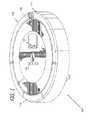
- FIG. 1is a front perspective view of a mobile robot incorporating an optical odometry camera.
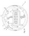
- FIG. 2Ais a bottom view of a mobile robot incorporating an optical odometry camera.
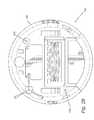
- FIG. 2Bis a bottom view of a mobile robot incorporating a plurality of optical odometry cameras.
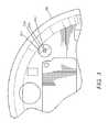
- FIG. 3is a view of the portion of the body of the mobile robot incorporating a recessed structure containing an optical odometry camera.
- FIG. 4is a cross-sectional view of the recessed structure containing the optical odometry camera.
- FIG. 5conceptually illustrates LED placement with respect to the optical odometry camera.
- FIG. 6is a cross-sectional view of the recessed structure containing the optical odometry camera illustrating the depth of field of the optical odometry camera.
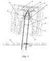
- FIG. 7is a cross-sectional view of the recessed structure containing the optical odometry camera illustrating the depth of field of the optical odometry camera in relation to a flat surface at a particular height when the mobile robot is tilted.
- FIG. 8is a cross-sectional view of the recessed structure containing the optical odometry camera illustrating the depth of field of the optical odometry camera in relation to a carpeted surface, where the carpet pile intrudes within the recessed structure.
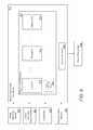
- FIG. 9conceptually illustrates the execution of a behavioral control application by a robot controller.
- FIG. 10conceptually illustrates a robot controller.
- FIG. 11is a flow chart illustrating a process for using odometry data captured by different types of odometry sensors.
- FIG. 12is a flow chart illustrating a process for using odometry data captured by different types of odometry sensors.
- FIGS. 13A-13Dare schematics illustrating implementations of LED configurations around a telecentric lens.
- the mobile robot 100can utilize an optical odometry sensor system 205 to perform dead reckoning.
- Dead reckoningis a process involving calculating the mobile robot's current position based upon a previously determined position and information about the movement of the mobile robot 100 .
- the mobile robot 100can use an optical odometry sensor system 205 to obtain odometry data, which may include different types of information used for dead-reckoning, including (but not limited to) distance traveled, direction of travel, velocity, and/or acceleration.
- the optical odometry sensor system 205can optionally include one or more optical odometry cameras 440 (i.e., mouse cameras) that capture images of a surface over which the mobile robot 100 traverses.
- the optical odometry sensor system 205includes one or more illumination sources that illuminate a tracking surface visible to an optical odometry camera 440 .
- the optical odometry camera 440can operate at a frame rate of over one thousand frames per second, capturing an image of a tiny patch of the tracking surface. The optical odometry sensor system 205 continuously compares each image captured by the optical odometry camera 440 to the one before it and estimates the relative motion of the mobile robot 100 based upon observed optical flow.
- the one or more optical odometry cameras 440may be located on an underside of the mobile robot body 108 and aimed toward the floor surface below the mobile robot 100 .
- Optical odometry sensors used in common applicationssuch as the optical odometry systems used in optical computer mice, typically assume that the optical odometry camera 440 is located a fixed distance from the tracking surface and utilize optical odometry cameras 440 with shallow depths of field.
- the mobile robot 100is configured to navigate over a variety of different surfaces and the assumption that tracking surface remains at a fixed distance from optical odometry camera 440 is not valid.
- the mobile robot body 108may tilt, increasing the distance between the optical odometry camera 440 and the tracking surface.
- the mobile robot 100navigates over uneven surfaces.
- the wheels of the mobile robot 100may sink into the compressible surface and decrease the distance between the optical odometry camera 440 and the tracking surface.
- the distance between the underside of the mobile robot 100 and a compressible surface such as a carpet pilemay continuously change, with the carpet fibers generally closer to the camera compared to a flat floor.
- the body 108 of the mobile robot 100can optionally include a recessed structure in the underside of the mobile robot body 108 that contains an optical odometry camera 440 and associated illumination source. Recessing the optical odometry camera 440 enables the use of an optical odometry camera 440 with a wider depth of field, which enables the optical odometry camera to capture in focus images of tracking surfaces at a comparatively wide range of distances from the optical odometry camera 440 encompassing the range of distances at which a tracking surface is likely to be encountered during the operation of the mobile robot 100 in a specific application.
- the depth of field of a camera configurationspecifies a range of distances between which images may be captured while still in-focus or within an acceptable range out of focus. Objects that lie outside of this acceptable range may not be useful for use in calculating odometry data.
- the optical odometry sensor system 205may not be able to detect the displacement of trackable features between images when the images are beyond an acceptable focus range.
- the depth of field of the optical odometry camera 440spans a range of distances including distances in which at least a portion of the tracking surface extends within the recessed structure containing the optical odometry camera 440 .
- the mobile robot 100is configured as a house cleaning robot 100 having a top surface 106 not more than 4 inches (or about 110 mm) from the floor surface and having a bottom surface 107 riding not more than about half an inch (or about 10 mm) above a floor surface.
- the bottom surface 107 , or underside, of the robot 100is located relatively close to the floor surface on which the mobile robot rests.
- the mobile robot 100can be configured using a recessed optical odometry camera 440 with a telecentric lens 442 having a depth of field ranging from approximately 20 millimeters to 40 millimeters from the camera.
- This range of distancesallows for in-focus images to be captured for surfaces at a height similar to a hardwood floor (e.g., approx. 20-30 mm below the camera) and surfaces at a height of a carpet (e.g., approx. 5-20 mm below the camera).
- the depth of field of the optical odometry camera 440can also accommodate increases in the distance between the optical odometry camera 440 and the floor surface, or tracking surface, due to unevenness of the floor surface and/or the mobile robot 100 traversing transitions between surfaces at different heights.
- the optical odometry camera 440uses a telecentric lens 442 to capture images of the tracking surface.
- Telecentric lensesare typically characterized by providing constant magnification of objects independent of distance.
- the use of a telecentric lensenables the optical odometry sensor system 205 to precisely determine optical flow of features on a tracking surface in a manner that is independent of the distance of the tracking surface from the optical odometry camera 440 .
- the mobile robot 100is able to precisely determine optical flow from tracking surfaces at a variety of depths from the mobile robot 100 without having to determine the distance to tracking surface.
- the mobile robot 100relies primarily on the optical odometry sensor system 205 to capture odometry data, but the mobile robot may use odometry data captured by other types of odometry sensors when the acquired optical odometry data is below a certain threshold level of accuracy for reason including (but not limited to) noise, and/or lack of trackable features on the tracking surface.
- the mobile robot 100determines that the odometry data is below a minimum level of reliability (for example, based on a minimum SQUAL value and/or conflicting IMU values)
- the mobile robotmay be optionally configured to rely upon odometry data captured by another sensor sampling at a high frequency, such as a wheel odometry sensor system.
- the wheel odometry sensor systemmay capture odometry data by analyzing the rotation of the wheels of the mobile robot 100 .
- the mobile robot 100may compare the odometry data provide by the optical odometry system and/or the wheel odometry sensor system against accelerometer and gyro data captured by an inertial measurement unit (IMU) to re-affirm the accuracy of the odometry data, for example confirming that the IMU senses the robot 100 is not moving when the mouse sensor sees no movement.
- IMUinertial measurement unit
- the mobile robot 100may increase (or decrease) a confidence level with respect to the accuracy of the optical odometry data based on the similarity of the data from the different devices.
- the mobile robot 100takes high frequency sensor readings to determine local position (for example, wheel odometry and IMU and/or optical odometry and IMU) and making a global determination of robot pose within an environment using more slowly sampled VSLAM localization data captured by an imaging sensor having a FOV aimed at a particular region of static landmarks.
- the robot 100determines an accurate pose within a global coordinate system and/or a persistent map of the environment and ignores, adjusts, and/or resets the high frequency local position data if there is a discrepancy in pose determination.
- Certain sensorsmay perform with better accuracy within certain environments while performing less accurately in others.
- the optical odometry sensor system 205provides accurate data when traveling over a floor surface that contains many trackable features, such as wood grain, but can lose accuracy when traveling over a smooth ceramic tile floor with few trackable features.
- a wheel odometercan provide accurate readings on flooring surfaces, such as solid flooring, on which the drive wheels 220 have good traction and less accurate readings while traveling over a deep carpeted floor because the wheels may experience greater amounts of slipping as the robot 100 encounters frictional resistance forces and/or carpet drift as the nap of the carpet steers the wheels off of a straight heading.
- the robot 100includes an IMU, such as a 6 axis IMU combining a 3-axis accelerometer with a 3-axis gyrometer (hereafter referred to as “gyro”).
- IMUsuch as a 6 axis IMU combining a 3-axis accelerometer with a 3-axis gyrometer
- the robot 100determines whether the wheel odometers and mouse sensors are properly reporting movement. For example, if a robot 100 is traveling over a smooth surface with too few features for the optical sensor to track and use to detect movement accurately, the mobile robot 100 will ignore the optical sensor data and default to one or more of other sensor readings to localize the robot 100 within the environment.
- the mobile robot 100incorporates an optical odometry sensor system 205 including an optical odometry camera 440 used to collect odometry data that can be used in the navigation of the mobile robot through an environment.
- the mobile robot 100is illustrated in FIGS. 1-2 .
- FIG. 1illustrates a front perspective view of the mobile robot 100
- FIG. 2illustrates a bottom view of the mobile robot 100 in which the recessed structure 210 containing the optical odometry sensor system 205 is visible.
- the mobile robot 100includes a body 108 supported by a drive (located beneath the body 108 and thus not visible in this illustration) that can maneuver the robot 100 across a floor surface.
- the mobile robot 100is configured to actuate its drive based on a drive command.
- the drive commandmay have x, y, and 0 components and the command may be issued by a controller circuit.
- the mobile robot body 108may have a forward portion 105 corresponding to the front half of the body 108 , and a rearward portion 110 corresponding the back half of the body 108 .
- the drive systemincludes right and left driven wheel modules 220 that may provide odometry to the controller circuit.
- the wheel modules 220are substantially opposed along a transverse axis defined by the body 108 and include respective drive motors driving respective wheels.
- the drive motorsmay releasably connect to the body 108 (e.g., via fasteners or tool-less connections) with the drive motors optionally positioned substantially over the respective wheels.
- the wheel modules 220can be releasably attached to the chassis and forced into engagement with the cleaning surface by springs.
- the mobile robotmay include a caster wheel (not illustrated) disposed to support a portion of the mobile robot body 108 , here, a forward portion of a round body 108 .
- the caster wheelis disposed in a reward portion of the robot body 108 .
- the mobile robot body 108supports a power source (e.g., a battery) for powering any electrical components of the mobile robot.
- a power sourcee.g., a battery
- the mobile robotcan utilize any of a variety of optional drive mechanisms as appropriate to the requirements of specific applications.
- a forward portion 105 of the body 108carries a bumper 115 , which can be utilized to detect (e.g., via one or more sensors) events including (but not limited to) obstacles in a drive path of the mobile robot.
- the controller circuitmay respond to events (e.g., obstacles, cliffs, walls) detected by the bumper by controlling the wheel modules 220 to maneuver the robot 100 in response to the event (e.g., away from an obstacle).
- a user interface 130is disposed on a top portion of the body 108 and can be used to receive one or more user commands and/or display a status of the mobile robot 100 .
- the user interface 130is in communication with the robot controller circuit carried by the mobile robot 100 such that one or more commands received by the user interface can initiate execution of a cleaning routine by the mobile robot 100 .
- the mobile robot 100may also include a machine vision system 120 embedded within the top cover of the mobile robot 100 .
- the machine vision system 120may include one or more cameras (e.g., standard cameras, volumetric point cloud imaging cameras, three-dimensional (3D) imaging cameras, cameras with depth map sensors, visible light cameras and/or infrared cameras) that capture images of the surrounding environment.
- a camera 120is positioned with its optical axis at an acute angle from the top surface of the robot 100 and the camera 120 has a field of view oriented in the direction motion of the mobile robot 100 .
- the lens of the camerais angled in an upwards direction such that it primarily captures images of the walls and ceilings surrounding the mobile robot in a typical indoor environment.
- a camera mounted under the top surface of the robot 100having a field of view spanning a frustum of approximate 50 degrees in the vertical direction and an optical axis angled at approximately 30 degrees above horizontal will detect features in the environment at a height of generally 3-14 feet.
- a robot of these dimensions with these camera settingswill see objects at a height of approximately 6 inches to 4.5 feet at a distance of 3 feet, at a height of approximately 9 inches to 7.5 feet at a distance of 5 feet and at a height of approximately 1.2 feet to 14 feet at a distance of 10 feet.
- the robot 100can identify reliable landmarks repeatedly, thereby accurately localizing and mapping within an environment.
- the images captured by the machine vision system 120may be used by VSLAM processes in order to make intelligent decisions about actions to take based on the mobile robot's operating environment. While the machine vision system 120 is described herein as being embedded on top of the mobile robot, cameras 120 can additionally or alternatively be arranged at any of various different positions on the mobile robot, including on the front bumper, bottom surface, and/or at locations along the peripheral sides of the mobile robot.
- the mobile robot 100may optionally include a variety of sensor systems in order to achieve reliable and robust autonomous movement.
- the additional sensor systemsmay be used in conjunction with one another to create a perception of the mobile robot's environment sufficient to allow the mobile robot 100 to make intelligent decisions about actions to take in that environment.
- one of the sensor systems included on the mobile robotis an optical odometry sensor system 205 that captures odometry data.
- the optical odometry sensorincludes one or more optical odometry cameras 440 positioned under the mobile robot body 108 to capture images of a tracking surface over which the mobile robot travels.
- Each optical odometry sensor system 205includes a camera that is positioned such that it is pointed directly at the tracking surface under the mobile robot.
- the optical odometry camera 440is positioned within a recessed structure 210 at a height of approximately 40-60 mm (e.g. 45 mm, 50 mm, 60 mm) from the tracking surface.
- the optical odometry camera 440includes a telecentric lens configured to capture images at a range of distances from the camera spanning a focal length of approximately negative 5 to positive 15 mm, or approximately 20 mm total.
- the depth of field of the optical odometry camera 440is proportional to the focal length.
- the optical odometry sensor system 205can compute a distance traveled by the mobile robot 100 by analyzing the optical flow of the images based on the time at which the images were captured.
- the odometry datamay be used in any of a variety of navigation processes including (but not limited to) a VSLAM process.
- the mobile robot 100may also capture movement information using various other types of sensors, including wheel odometry sensors, gyroscopes, accelerometers, global positioning systems (GPS), compasses, among other sensors capable of providing information regarding the movement of the mobile robot within the environment.
- the movement information provided by different movement sensorsmay include new types of information (e.g., a direction of movement, orientation, acceleration, GPS coordinates, etc. of the mobile robot) and/or the same types of information captured through different mechanisms (e.g., wheel and optical odometers may both provide information regarding a distance traveled).
- the various sensor systemsmay also include one or more types of sensors supported by the robot body 108 including, but not limited to, obstacle detection obstacle avoidance (ODOA) sensors, communication sensors, navigation sensors, range finding sensors, proximity sensors, contact sensors, sonar, radar, LIDAR (Light Detection And Ranging, which can entail optical remote sensing that measures properties of scattered light to find range and/or other information of a distant target), and/or LADAR (Laser Detection and Ranging).
- the sensor systemincludes ranging sonar sensors, proximity cliff detectors, contact sensors, a laser scanner, and/or an imaging sonar.
- the sensorsare typically placed such that they have maximum coverage of areas of interest around the mobile robot.
- the sensorsare typically placed in such a way that the robot itself causes an absolute minimum of occlusion to the sensors; in essence, the sensors should not be placed such that they are blinded by the robot itself. Accordingly, the sensors should be mounted in a manner so as not to interfere with normal robot operation (e.g., snagging on obstacles).
- the mobile robot 100can be configured so that the optical odometry sensor system 205 is located within a recessed structure 210 formed within the underside of the mobile robot body 108 .
- the optical odometry camera 440is able to (1) capture images of the surface under the mobile robot, (2) avoid contact with objects that may damage the camera, and (3) have an optical system capable of capturing in-focus images at a variety of different distances.
- FIGS. 2A-2BPlacement of one or more optical odometry sensor systems with respect to the underside of the mobile robot 100 in accordance with embodiments of the invention is illustrated in FIGS. 2A-2B .
- FIG. 2Aillustrates the recessed structure 210 containing the optical odometry sensor system 205 positioned in the front right region of the underside of the rounded mobile robot body 108 .
- FIG. 2Aalso illustrates various other components that may be optionally included on the mobile robot 100 , including the right and left wheel modules 220 , side brush 230 , and cleaning assembly 240 .
- FIG. 2Billustrates two optical odometry sensor systems 205 , 250 located on opposite sides of the underside of the mobile robot 100 .
- Configuring the mobile robot 100 with two or more optical odometry sensor systemscan increase the accuracy of the odometry data.
- Using two optical odometry sensor systems 205 , 250permits cross checking of the odometry data being generated by each individual optical odometry sensor system.
- the mobile robot 100may rely on the other optical odometry sensor 205 , 250 system to collect odometry data.
- FIG. 3illustrates the recessed structure 210 containing the optical odometry sensor system in more detail.
- the optical odometry camera 440is positioned within a rounded recessed structure 210 in the underside of the mobile robot body.
- the recessed structure 210can have a diameter 211 large enough to enable a human finger to fit therein for the removal of foreign objects or debris (FOD).
- the diameter of the recessed structure 210is between 0.5 and 1.5 inch (e.g. 0.5 to 1 inch, 0.75 to 1.5 inch, 0.5 to 0.75 inch, 0.75 to 1 inch).
- the optical axis of the optical odometry camera 440is directed outwards so that the camera can capture images of a tracking surface while the mobile robot 100 moves along the surface.
- optical odometry sensor systemscan include an optical odometry camera 440 that captures images of a surface and uses the images to compute odometry data.
- the optical odometry camera 440may run at a frame rate of over one thousand frames per second, capturing an image of a tiny patch of the tracking surface.
- the image patch 1330is approximately 1 mm by 1 mm (e.g. 0.5 mm by 0.5 mm, 0.5 mm by 0.75 mm, 0.5 mm by 1 mm, 0.75 mm by 1 mm, 1.5 mm by 1.5 mm).
- the optical odometry sensor system 205continuously compares displacement of trackable features in each image captured by the optical odometry camera 440 to the one before it, using optical flow to estimate the relative motion of the mobile robot.
- the tracking surfaceIn order for the optical odometry camera 440 to capture in-focus images for use in determining optical flow, the tracking surface must be located a distance from the camera that remains within an acceptable focal range within the depth of field of the optical axis of the optical odometry camera 440 .
- an acceptable focal rangeis one that includes carpet extending into the recessed structure 210 and tile having peaks and valleys, such as slate.
- the image patch 1330is 22 pixels by 22 pixels and the acceptable depth of field of the optical odometry camera 440 is determined by blurring an image patch 1330 until one pixel bleeds into an adjacent pixel.
- An acceptable amount of blurmay be, for example, a depth of field that blurs pixels without bleeding between pixels in the image patch 1330 or bleeding of up to two adjacent pixels within the image patch 1330 .
- the optical odometry camera 440is configured with a comparatively wide depth of field such that it is able to capture in-focus and/or acceptably blurry images of tracking surfaces positioned at various distances from the optical odometry camera 440 .
- the mobile robotmay use a recessed structure under the mobile robot body 108 to allow for the use of an optical odometry camera 440 having a wide depth of field.
- An example of a recessed structure 210 that can be used to house a recessed optical odometry systemis illustrated in FIG. 4 .
- FIG. 4conceptually illustrates a cross-sectional view of an optional configuration of the mobile robot 100 in which an optical odometry camera 440 is mounted within a recessed structure 210 within the mobile robot body 108 .
- the optical odometry camera 440is contained within a recessed structure under the mobile robot body 108 .
- the recessed structure 210includes an opening 410 .
- the sensor 430 and optics 440 of the optical odometry camera 440are located within the recessed structure 210 to capture images through the opening 410 in the recessed structure.
- the recessed structure 210can be optionally configured to form a chamber between the optics of the camera 440 and the opening 410 .
- the mobile robot 100can be optionally configured with an optical odometry camera 440 that has a depth of field extending over a range of distances including distances that are within the recessed structure 210 and distances that are beyond the opening 410 of the recessed structure 210 . All surfaces of the recessed structure 210 are out of focus so that the camera 440 does image any dust collected on those surfaces to the sensor 430 .
- the recessed structure 210has a diameter 211 large enough to enable a human finger to fit therein for the removal of foreign objects or debris (FOD).
- the diameter 211 of the recessed structure 210is between 0.5 and 1.5 inch or approximately 10 mm to 40 mm (e.g. 0.5 to 1 inch, 0.75 to 1.5 inch, 0.5 to 0.75 inch, 0.75 to 1 inch).
- the mobile robot 100use the recessed structure to place the optical odometry camera 440 significantly above the tracking surface in order to eliminate the potential of having objects damage the camera, including a lens cover 441 of the camera 440 , while the mobile robot 100 travels through an environment.
- locating the optical odometry camera 440 at a height that is likely to avoid contact with the tracking surface and/or objects located on the tracking surfacecan significantly reduce the likelihood of damage to the optical odometry camera 440 .
- the opening 410 of the recessed structure 210aligns with the bottom surface of the robot 100 and is approximately 10 mm from the floor surface beneath the robot 100 .
- the recessed structure 210accommodates an optical odometry camera 440 having a focal length of approximately 15-25 mm, (e.g., 17 mm, 18 mm, 19 mm, 20 mm), a pinhole aperture and a depth of field of 40-60 mm (e.g., 45 mm, 50 mm, 55 mm)
- the optical odometry camera 440therefore, is configured to collect odometry data from surfaces positioned at various different distances beneath the mobile robot within the acceptable focal range of, for example, negative 5 mm to 15 mm, for a total range of 20 mm.
- the optical odometry camera 440is positioned within the recessed structure at a distance of approximately 40-60 mm (e.g. 45 mm, 50 m, 55 mm) from the bottom of the robot in order to obtain the necessary depth of field for a focal range of negative 5 mm to 15 mm.
- the camera configurationprovides a depth of field that captures in-focus images of hard floor surfaces (e.g., hardwood floors) and closer floor surfaces (e.g., plush carpet), which are likely to vary in distance from the camera by approximately 20-25 mm.
- the optical odometry camera 440uses a telecentric lens 442 that allows the optical odometry sensor system 205 to determine the precise size of objects independently from their depth within the field of view of the camera 440 .
- Telecentric lenseshave a constant magnification of objects independent of their distance.
- the optical odometry sensor system 205can determine the magnitude of movement from optical flow without having to determine the distance to the tracking surface in order to scale the magnitude of the optical flow.
- Optical odometry sensor systemsmay use an LED or laser to illuminate the tracking surface being imaged by the optical odometry camera 440 .
- an LED designthat provides uniform illumination of the tracking surface.
- LED configurationsthat can be utilized to illuminate tracking surfaces are discussed below below.
- the optical odometry sensor system 205includes an optical odometry camera 440 surrounded by at least two LEDs positioned around the camera lens 442 .
- An example of an optical odometry camera 440 with four LEDs positioned surrounding the camera lens 442is illustrated in FIG. 5 .
- FIG. 5illustrates an optical odometry camera 440 that includes four LEDs 510 positioned around the optical odometry camera lens 442 of the system.
- each LED 510is angled to increase the uniformity of the illumination of the tracking surface. In some embodiments, each LED 510 is angled at approximately 10-20 degrees (e.g. 12 degrees, 15 degrees, 17 degrees) from vertical to provide the optimal illumination (e.g., illumination of trackable features on the floor surface 520 without shadowing) of the surface based on the recess structure 410 holding the camera. In some implementations, the emission cones 511 of the LEDs overlap on a surface for a combined illumination and in other implementations, the emission cones do not converge.
- FIGS. 13A-13Billustrate, in one example, four LEDS 1310 , 1315 , 1320 , 1325 are angled so that their emissions converge on the optical axis 1305 of a telecentric lens of the optical odometry camera 440 at a middle distance d 2 in the field of view.
- the illumination from all four LEDS 1310 , 1315 , 1320 , 1325overlap in a circle and the usable image patch 1330 is limited to an area within the convergent circles because brightness falls off at the outer edges of the illuminated circle, which may make only a portion of the illuminated area useful for tracking.
- FIGS. 13A-13Billustrate, in one example, four LEDS 1310 , 1315 , 1320 , 1325 are angled so that their emissions converge on the optical axis 1305 of a telecentric lens of the optical odometry camera 440 at a middle distance d 2 in the field of view.
- the four LEDS 1310 , 1315 , 1320 , 1325are each aimed so that their emissions are offset from the optical axis 1305 of the telecentric optical odometry camera lens 442 .
- the emissions from the four LEDS 1310 , 1315 , 1320 , 1325therefore do not converge at a single circle.
- each of the emissionsoverlaps with two other emissions at an overlap patch 1335 a - 1335 d such that the trackable area illuminated by the four LEDS 1310 , 1315 , 1320 , 1325 is greater than in a fully convergent implementation.
- This spiral illumination patternprovides for fewer areas of brightness drop off and a larger illuminated coverage area for detecting trackable features within the image patch. More critically, the spiral illumination pattern of FIGS. 13C-D provides even illumination of the surface below the camera 400 without any bright spots that would flood the camera and wash out the remaining portion of the imaged area. The spiral pattern of FIGS. 13C-D therefore provides less illumination than all four light emissions overlapping in one location. By overlapping no more than two light emissions from two LEDs in any one area the illumination on the surface below the camera 440 is maintained at light intensity below a threshold level of brightness that would dominate the image and wash out otherwise perceptible details around the intensely bright spot.
- An optical odometry camera 440that can capture images that are in focus over a range of distances can be particularly useful when the mobile robot travels across different types of surfaces that may be at different distances beneath the underside of the mobile robot.
- FIGS. 6-8conceptually illustrate the manner in which an optical odometry camera 440 having a wide depth of field can capture precise optical odometry data in a range of real world conditions that are particularly likely to be encountered when the mobile robot 100 is configured as a housecleaning robot riding at approximately 10 mm above a floor surface.
- FIG. 6conceptually illustrates the depth of field 601 of the optical odometry camera 440 illustrated in FIG. 4 using light rays 620 .
- the depth of field 601extends from a first distance 630 within the chamber formed by the recessed structure 210 in front of the optical odometry camera 440 having a telecentric lens 442 to a second distance 640 beyond the opening 410 of the recessed structure 210 .
- a surface positioned within this rangewill generally be captured in-focus by the optical odometry camera 440 and thus may be used to ascertain optical odometry data. Examples of different types of surfaces located at different distances from the optical odometry system are conceptually illustrated in FIG. 7 and FIG. 8 .
- FIG. 7conceptually illustrates the mobile robot 100 traveling across hard surface, such as hardwood floor or tile floor. Furthermore, the mobile robot 100 is tilted relative to the floor. The mobile robot 100 may tilt for any of a variety of reasons including (but not limited to) traveling over an object, when the floor is uneven, and/or traversing a transition between floor surfaces at different heights. Even with the increase in the distance between the mobile robot and the tracking surface that results when the mobile robot 100 is tilted, the depth of field 601 of the optical odometry camera 440 is sufficiently large so as to continue to capture in-focus images and/or acceptably out of focus images of the portion of the tracking surface visible through the opening 410 in the recessed structure 210 containing the optical odometry sensor system.
- FIG. 8conceptually illustrates the mobile robot 100 traveling over a carpeted surface.
- Carpet fibers 810are intruding through the opening 410 into the recessed structure 210 as would occur if the height of the carpet exceeds the distance between the underside of the mobile robot and the bottom of the wheels.
- the depth of field 601 of the optical odometry camera 440is sufficiently large so as to enable the capture of in focus and acceptably blurry images of the carpet.
- the optical odometry sensor system 205is able to capture odometry data for a variety of different types of surfaces that may be located at different distances under the mobile robot.
- the conceptual operation of mobile robots configured by robot controllers in accordance with various embodiments of the inventionare discussed further below.
- the mobile robot 100can optionally be configured using behavioral control applications that determine the mobile robot's behavior based upon the surrounding environment and/or the state of the mobile robot 100 .
- the mobile robotcan include one or more behaviors that are activated by specific sensor inputs and an arbitrator determines which behaviors should be activated.
- sensor inputscan include images of the environment surrounding the mobile robot 100 and behaviors can be activated in response to characteristics of the environment ascertained from one or more captured images.
- the mobile robot 100 behavioral control application 910can receive information regarding its surrounding environment from one or more sensors, including a wheel odometry sensor 920 , optical odometry sensor system 921 , gyroscope 922 , and a machine vision system 923 .
- one or more other sensorse.g., bump, proximity, wall, stasis, and/or cliff sensors
- the wheel odometry sensor 920captures odometry data based on the rotation of the wheels of the mobile 100 . The accuracy of this odometry data may vary based on the particular type of surface over which the mobile robot 100 traverses. For example, in a deep carpeted surface, the wheels may slip diminishing the accuracy of the odometry data.
- the optical odometry sensor system 921gathers odometry data using images captured by a camera 440 as the mobile robot 100 traverses across a surface of an environment.
- the odometry data captured by the optical odometry camera 440may include information regarding a translational distance and direction travelled by the mobile robot 100 . In some configurations, however, this odometry data may not include information regarding a direction of motion of the mobile robot 100 .
- Direction of motion informationmay be gathered from several different types of sensors, including a gyroscope, compass, accelerometer among various other sensors capable of providing this information.
- the gyroscope sensor 922captures orientation data of the mobile robot 100 as it travels through the environment.
- the data captured from the various sensors 920 - 923may be combined in order to ascertain various information regarding the movement and pose of the mobile robot 100 .
- the mobile robot behavioral control application 910can control the utilization of robot resources 925 (e.g., the wheels modules 220 ) in response to information received from the sensors 960 , causing the mobile robot 100 to actuate behaviors, which may be based on the surrounding environment.
- the programmed behaviors 930may include various modules that may be used to actuate different behaviors of the mobile robot 100 .
- the programmed behaviors 730may include a VSLAM module 940 and corresponding VSLAM database 944 , a navigation module 942 , and a number of additional behavior modules 943 .
- the mobile robot behavioral control application 910can be implemented using one or more processors in communication with memory containing non-transitory machine readable instructions that configure the processor(s) to implement a programmed behaviors system 930 and a control arbitrator 950 .
- the VSLAM module 940manages the mapping of the environment in which the mobile robot 100 operates and the localization of the mobile robot with respect to the mapping.
- the VSLAM module 940can store data regarding the mapping of the environment in the VSLAM database 944 .
- the datamay include a map of the environment and characteristics of different regions of the map including, for example, regions that contain obstacles, other regions that contain traversable floor, regions that have been traversed, regions that have not yet been traversed, the date and time of the information describing a specific region, and/or additional information that may be appropriate to the requirements of a specific application.
- the VSLAM databasealso includes information regarding the boundaries of the environment, including the location of stairs, walls, and/or doors.
- many other types of datamay be stored and utilized by the VSLAM module 940 in order to map the operating environment of a mobile robot 100 as appropriate to the requirements of specific applications in accordance with embodiments of the invention.
- the navigation module 942actuates the manner in which the mobile robot 100 is to navigate through an environment based on the characteristics of the environment.
- the navigation module 942may direct the mobile robot 100 to change directions, drive at a certain speed, drive in a certain manner (e.g., wiggling manner to scrub floors, a pushing against a wall manner to clean sidewalls, etc.), navigate to a home charging station, and various other behaviors.
- behaviors 943may also be specified for controlling the behavior of the mobile robot. Furthermore, to make behaviors 940 - 943 more powerful, it is possible to chain the output of multiple behaviors together into the input of another behavior module to provide complex combination functions.
- the behaviors 940 - 943are intended to implement manageable portions of the total cognizance of the mobile robot and, as can be readily appreciated, mobile robots can incorporate any of a variety of behaviors appropriate to the requirements of specific applications.
- the control arbitrator 950facilitates allowing modules 940 - 943 of the programmed behaviors 930 to each control the mobile robot 100 without needing to know about any other behaviors.
- the control arbitrator 950provides a simple prioritized control mechanism between the programmed behaviors 930 and resources 925 of the mobile robot 100 .
- the control arbitrator 950may access behaviors 940 - 943 of the programmed behaviors 930 and control access to the robot resources 960 among the behaviors 940 - 943 at run-time.
- the control arbitrator 950determines which module 940 - 943 has control of the robot resources 960 as required by that module (e.g. a priority hierarchy among the modules).
- Behaviors 940 - 943can start and stop dynamically and run completely independently of each other.
- the programmed behaviors 930also allow for complex behaviors that can be combined together to assist each other.
- the robot resources 960may be a network of functional modules (e.g., actuators, drive systems, and groups thereof) with one or more hardware controllers.
- the commands of the control arbiter 950are typically specific to the resource to carry out a given action.
- the conceptual operation of the mobile robot when configured by a robot controller circuitis discussed further below.
- the behavior of the mobile robot 100 when configured by a robot controller circuitis typically selected from a number of behaviors based upon the characteristics of the mobile robot's surrounding operating environment and/or the state of the mobile robot 100 .
- characteristics of the environmentmay be ascertained from images captured by a machine vision sensor system and movement through the environment can be tracked using images captured by an optical odometry camera 440 . Captured images can be used by one or more VSLAM processes to map the environment surrounding the mobile robot 100 and localize the position of the mobile robot 100 within the environment.
- the robot controller circuit 1005includes a processor 1010 in communication with a memory 1025 and an input/output interface 1020 .
- the processor 1010can be a single microprocessor, multiple microprocessors, a many-core processor, a microcontroller, and/or any other general purpose computing system that can be configured by software and/or firmware.
- the memory 1025contains a visual measurement application 1030 , a VSLAM application 1035 , a map of landmarks 1040 , a behavior control application 1045 and a landmarks database 1050 .
- the visual measurement application 1030identifies features within a set of input images and identifies a landmark from the landmark database 1050 based upon the similarity of the collection of features identified in the input images to a matching the collection of features associated with the identified landmark from the landmarks database 1050 .
- the visual measurement applicationcan also generate new landmarks by identifying a set of features within a series of captured images, analyzing the disparity information of the set of features to determine the 3D structure of the features, and storing the 3D features as a new landmark within the landmarks database 1050 .
- the VSLAM application 1035estimates the location of the mobile robot 100 within a map of landmarks based upon a previous location estimate, odometry data, and at least one visual measurement received from the visual measurement application. As noted above, the images may be utilized by a VSLAM application 1035 . In certain embodiments, features are extracted from a newly acquired image and the features are compared to features previously detected and saved within the landmarks database 1050 . The VSLAM application 1035 updates the map of landmarks based upon the estimated location of the mobile robot 100 , the odometry data, and the at least one visual measurement.
- the map of landmarks 1040can include a map of the environment surrounding the mobile robot 100 and the position of landmarks relative to the location of the mobile robot 100 within the environment.
- the map of landmarks 1040may include various pieces of information describing each landmark in the map, including (but not limited to) references to data describing the landmarks within the landmarks database.
- the behavioral control application 1030controls the actuation of different behaviors of the mobile robot 100 based on the surrounding environment and the state of the mobile robot 100 .
- the behavioral control application 1045determines how the mobile robot 100 should behave based on the understanding of the environment surrounding the mobile robot 100 .
- the behavioral control application 1045may select from a number of different behaviors based on the particular characteristics of the environment and/or the state of the mobile robot 100 .
- the behaviorsmay include, but are not limited to, a wall following behavior, an obstacle avoidance behavior, an escape behavior, among many other primitive behaviors that may be actuated by the robot.
- the input/output interfaceprovides devices such as (but not limited to) sensors with the ability to communicate with the processor and/or memory.
- the input/output interfaceprovides the mobile robot with the ability to communicate with remote computing devices via a wired and/or wireless data connection.
- the mobile robot 100can be configured using any of a variety of robot controllers as appropriate to the requirements of specific applications including robot controllers configured so that the robot behavioral controller application is located on disk or some other form of storage and is loaded into memory at runtime and/or where the robot behavioral controller application is implemented using a variety of software, hardware, and/or firmware.
- the reliability of the odometry data provided by the optical odometry sensor system 205may vary based on various factors, including (but not limited to) the type of surface being traversed, the illumination of the surface, the speed of the mobile robot across the surface, and/or the frame rate of the optical odometry camera 440 .
- the mobile robot 100may obtain additional odometry data using one or more different type of sensors, including (but not limited to) one or more wheel odometry sensors.
- the mobile robot 100may compare the odometry data captured by the optical odometry sensor system 205 against the odometry data captured by wheel odometry sensors in order to ascertain the reliability of the optical odometry data and/or to provide more reliable odometry data to other processes.
- the mobile robotmay rely primarily on the optical odometry sensor system 205 to capture odometry data. However, when the optical odometry sensor system 205 is unable to capture odometry data with a satisfactory level of reliability, the mobile robot 100 may also use the wheel odometry sensor system to gather the odometry data. For example, if a the mobile robot 100 travels across a ceramic tile floor with too few trackable features to achieve a reliable SQUAL value, the optical odometry data may not be as accurate as data captured by other types of sensors including, for example, a wheel odometry sensor. A processes that can optionally be utilized by the mobile robot 100 to obtain odometry data using information captured by different types of sensors are illustrated in FIGS. 11 and 12 .
- the process 1100receives ( 1102 ) sensor data from one or more different sensors.
- the sensorsmay include (but is not limited to) an optical odometry sensor system, and/or a wheel odometry sensor, a machine vision sensor.
- the mobile robot 100determines ( 1104 ) whether the optical odometry data captured by the optical odometry sensor system 205 satisfies a quality threshold.
- the optical odometry sensor system 205provides a quality metric with the odometry data that provides an estimate of the reliability of the data.
- the quality metricmay be based on the surface quality over which the mobile robot is traversing, based on, for example, whether the sensor has features to track.
- the mobile robot 100can use ( 1106 ) the optical odometry data to estimate a distance travelled. If the optical odometry data does not satisfy the quality threshold, the mobile robot 100 can use ( 1108 ) the optical odometry data and data from one or more additional sensor(s) to estimate the distance travelled.
- the additional sensormay be a wheel odometry sensor that captures odometry data based on the rotation of the wheels of the mobile robot 100 across the environment.
- the wheel odometry datais used to verify the optical odometry data and the optical odometry data is utilized when confirmed by the wheel odometry data.
- the processmay discard all odometry data and/or rely upon the wheel odometry data as appropriate to the requirements of the specific application.
- the mobile robot 100uses ( 1110 ) a gyroscope and/or additional sensors to estimate a direction of movement of the mobile robot 100 through the environment and updates ( 1112 ) the mobile robot pose based on the estimated extent of the translation and direction of the movement.
- the mobile robot 100receives S 1205 high frequency sensor readings from the wheel odometry and IMU and/or optical odometry and IMU.
- the robot 100comprises an IMU, such as a 6 axis IMU combining a 3-axis accelerometer with a 3-axis gyrometer (hereafter referred to as “gyro”).
- the robot 100determines whether the wheel odometers and mouse sensors are accurately reporting movement and can be considered in determining robot location within an operating environment. For example, if a robot 100 is traveling over a smooth surface with too few features for the optical sensor to track for detecting movement accurately, the sensor will produce a low SQUAL value. The process 1200 determines S 1220 whether the SQUAL value is below a threshold and if so, the robot 100 will ignore S 1225 the optical sensor data and default to one or more of other sensor readings to localize the robot 100 within the environment.
- the robot 100issues an audible and/or visual signal to a user that FOD may be obstructing the lens of the optical odometry camera 440 and prompts the user to clean out the recess 210 .
- the robot 100ignores S 1230 the wheel odometry data in making a determination of localization. If the IMU and wheel odometer both indicate that the robot 100 is moving, the robot 100 checks S 1235 whether the IMU indicates drift from an initial robot heading.
- the robot 100ignores S 1240 the wheel odometry data and optical sensor data and adjusts that localization with a global determination of robot pose within the environment using more slowly sampled VSLAM data.
- the robot 100has an imaging sensor configured to collect images for VSLAM, the imaging sensor being a camera 120 having a field of view aimed at a particular region of static landmarks in the height range of 3-8 feet from the floor surface.
- the robot 100determines S 1245 an accurate pose within a global coordinate system and/or a persistent map of the environment and ignores, adjusts, and/or resets S 1250 the high frequency local position data if there is a discrepancy in localization once pose is determined.
- the process 1200then checks S 1225 whether the robot mission, (e.g., a cleaning run) is complete and returns to monitoring the wheel odometry sensor data, optical odometry data and IMU data.
- the process 1200 running on the robot 100will localize S 1260 the robot 100 using both wheel odometry data and optical sensor data.
- the process 1200includes an intermittent global localization check to insure that the robot has not drifted significantly despite input from the IMU. The global localization check first determines S 1265 whether a threshold duration has passed. If not, the process checks S 1225 whether the robot mission, (e.g., a cleaning run) is complete and returns to monitoring the wheel odometry sensor data, optical odometry data and IMU data.
- the process 1200determines S 1270 the pose of the robot 100 using the VSLAM sensor, as described above. If the process determines that the odometry based localization and VSLAM pose are aligned, the process 1200 then checks S 1225 whether the robot mission, (e.g., a cleaning run) is complete and returns to monitoring the wheel odometry sensor data, optical odometry data and IMU data. If the process 1200 determines that the odometry based localization and VSLAM pose are not aligned, the robot 100 ignores, adjusts, and/or resets S 1250 the high frequency local position data.
- the robot missione.g., a cleaning run
Landscapes
- Engineering & Computer Science (AREA)
- Remote Sensing (AREA)
- Physics & Mathematics (AREA)
- Radar, Positioning & Navigation (AREA)
- Aviation & Aerospace Engineering (AREA)
- Automation & Control Theory (AREA)
- General Physics & Mathematics (AREA)
- Computer Vision & Pattern Recognition (AREA)
- Electromagnetism (AREA)
- Multimedia (AREA)
- Mechanical Engineering (AREA)
- Robotics (AREA)
- Control Of Position, Course, Altitude, Or Attitude Of Moving Bodies (AREA)
- Length Measuring Devices By Optical Means (AREA)
- Manipulator (AREA)
Abstract
Description
Claims (18)
Priority Applications (5)
| Application Number | Priority Date | Filing Date | Title |
|---|---|---|---|
| US14/856,501US9744670B2 (en) | 2014-11-26 | 2015-09-16 | Systems and methods for use of optical odometry sensors in a mobile robot |
| PCT/US2015/061146WO2016085716A1 (en) | 2014-11-26 | 2015-11-17 | Systems and methods of use of optical odometry sensors in a mobile robot |
| CN201580039003.9ACN106489104B (en) | 2014-11-26 | 2015-11-17 | System and method for use of optical odometry sensors in a mobile robot |
| EP15863494.9AEP3224003B1 (en) | 2014-11-26 | 2015-11-17 | Systems and methods of use of optical odometry sensors in a mobile robot |
| JP2017518191AJP6772129B2 (en) | 2014-11-26 | 2015-11-17 | Systems and methods for the use of optical mileage sensors in mobile robots |
Applications Claiming Priority (2)
| Application Number | Priority Date | Filing Date | Title |
|---|---|---|---|
| US201462085002P | 2014-11-26 | 2014-11-26 | |
| US14/856,501US9744670B2 (en) | 2014-11-26 | 2015-09-16 | Systems and methods for use of optical odometry sensors in a mobile robot |
Publications (2)
| Publication Number | Publication Date |
|---|---|
| US20160144511A1 US20160144511A1 (en) | 2016-05-26 |
| US9744670B2true US9744670B2 (en) | 2017-08-29 |
Family
ID=56009312
Family Applications (1)
| Application Number | Title | Priority Date | Filing Date |
|---|---|---|---|
| US14/856,501Active2035-10-05US9744670B2 (en) | 2014-11-26 | 2015-09-16 | Systems and methods for use of optical odometry sensors in a mobile robot |
Country Status (5)
| Country | Link |
|---|---|
| US (1) | US9744670B2 (en) |
| EP (1) | EP3224003B1 (en) |
| JP (1) | JP6772129B2 (en) |
| CN (1) | CN106489104B (en) |
| WO (1) | WO2016085716A1 (en) |
Cited By (5)
| Publication number | Priority date | Publication date | Assignee | Title |
|---|---|---|---|---|
| EP3546882A1 (en)* | 2018-03-27 | 2019-10-02 | Toyota Jidosha Kabushiki Kaisha | Moving amount detection device |
| US20200072972A1 (en)* | 2018-08-29 | 2020-03-05 | Quanta Computer Inc. | Tracking-distance-measuring system for torso tracking and method thereof |
| US11685049B2 (en) | 2020-04-22 | 2023-06-27 | Boston Dynamics, Inc. | Robot localization using variance sampling |
| USD1017154S1 (en)* | 2020-09-17 | 2024-03-05 | Irobot Corporation | Mobile cleaning robot |
| US12356087B2 (en) | 2020-07-08 | 2025-07-08 | Cognex Corporation | System and method for extending depth of field for 2D vision system cameras in the presence of moving objects |
Families Citing this family (54)
| Publication number | Priority date | Publication date | Assignee | Title |
|---|---|---|---|---|
| US10691097B2 (en) | 2014-05-09 | 2020-06-23 | The Boeing Company | Path repeatable machining for full sized determinant assembly |
| US9744670B2 (en) | 2014-11-26 | 2017-08-29 | Irobot Corporation | Systems and methods for use of optical odometry sensors in a mobile robot |
| EP3230814B1 (en) | 2014-12-10 | 2021-02-17 | Aktiebolaget Electrolux | Using laser sensor for floor type detection |
| US11099554B2 (en) | 2015-04-17 | 2021-08-24 | Aktiebolaget Electrolux | Robotic cleaning device and a method of controlling the robotic cleaning device |
| US10121255B2 (en) | 2015-11-03 | 2018-11-06 | Pixart Imaging Inc. | Optical sensor for odometry tracking to determine trajectory of a wheel |
| WO2017157421A1 (en)* | 2016-03-15 | 2017-09-21 | Aktiebolaget Electrolux | Robotic cleaning device and a method at the robotic cleaning device of performing cliff detection |
| CN106352870B (en)* | 2016-08-26 | 2019-06-28 | 深圳微服机器人科技有限公司 | A kind of localization method and device of target |
| US10571925B1 (en) | 2016-08-29 | 2020-02-25 | Trifo, Inc. | Autonomous platform guidance systems with auxiliary sensors and task planning |
| US10571926B1 (en) | 2016-08-29 | 2020-02-25 | Trifo, Inc. | Autonomous platform guidance systems with auxiliary sensors and obstacle avoidance |
| US10162362B2 (en)* | 2016-08-29 | 2018-12-25 | PerceptIn, Inc. | Fault tolerance to provide robust tracking for autonomous positional awareness |
| US10402663B1 (en) | 2016-08-29 | 2019-09-03 | Trifo, Inc. | Visual-inertial positional awareness for autonomous and non-autonomous mapping |
| US11314262B2 (en) | 2016-08-29 | 2022-04-26 | Trifo, Inc. | Autonomous platform guidance systems with task planning and obstacle avoidance |
| US10395117B1 (en) | 2016-08-29 | 2019-08-27 | Trifo, Inc. | Visual-inertial positional awareness for autonomous and non-autonomous tracking |
| US10453213B2 (en) | 2016-08-29 | 2019-10-22 | Trifo, Inc. | Mapping optimization in autonomous and non-autonomous platforms |
| US10043076B1 (en) | 2016-08-29 | 2018-08-07 | PerceptIn, Inc. | Visual-inertial positional awareness for autonomous and non-autonomous tracking |
| JP6380490B2 (en)* | 2016-09-12 | 2018-08-29 | カシオ計算機株式会社 | Printing apparatus, printing method, and program |
| US10722775B2 (en)* | 2016-09-27 | 2020-07-28 | Adidas Ag | Robotic training systems and methods |
| US10732127B2 (en)* | 2016-10-26 | 2020-08-04 | Pixart Imaging Inc. | Dirtiness level determining system and surface cleaning machine |
| US10642277B2 (en)* | 2017-03-22 | 2020-05-05 | Fetch Robotics, Inc. | Cleaning station for mobile robots |
| KR102426728B1 (en)* | 2017-04-10 | 2022-07-29 | 삼성전자주식회사 | Method and electronic device for focus control |
| US10627518B2 (en)* | 2017-06-02 | 2020-04-21 | Pixart Imaging Inc | Tracking device with improved work surface adaptability |
| EP3629869B1 (en) | 2017-06-02 | 2023-08-16 | Aktiebolaget Electrolux | Method of detecting a difference in level of a surface in front of a robotic cleaning device |
| US10444761B2 (en) | 2017-06-14 | 2019-10-15 | Trifo, Inc. | Monocular modes for autonomous platform guidance systems with auxiliary sensors |
| WO2019012942A1 (en)* | 2017-07-11 | 2019-01-17 | パナソニックIpマネジメント株式会社 | Robot controller |
| CN107329476A (en)* | 2017-08-02 | 2017-11-07 | 珊口(上海)智能科技有限公司 | A kind of room topology map construction method, system, device and sweeping robot |
| CN107894230A (en)* | 2017-12-31 | 2018-04-10 | 天津阿备默机器人科技有限公司 | A kind of AGV carriers navigation sensor |
| CN108245099A (en)* | 2018-01-15 | 2018-07-06 | 深圳市沃特沃德股份有限公司 | Robot moving method and device |
| CN110442120B (en)* | 2018-05-02 | 2022-08-05 | 深圳市优必选科技有限公司 | Method for controlling robot to move in different scenes, robot and terminal equipment |
| US10751875B2 (en)* | 2018-05-31 | 2020-08-25 | Indoor Robotics Ltd | Rotatable mobile robot for mapping an area and a method for mapping the same |
| KR102047303B1 (en)* | 2018-06-01 | 2019-11-21 | 엘지전자 주식회사 | Robot of estimating direction based on vanishing point of low luminance image and method estimating thereof |
| GB2574417B (en)* | 2018-06-05 | 2021-03-03 | Dyson Technology Ltd | A vision system for a mobile robot |
| WO2020013043A1 (en)* | 2018-07-13 | 2020-01-16 | Whill株式会社 | Electric mobility apparatus |
| CN109506652B (en)* | 2018-10-23 | 2022-11-15 | 珠海一微半导体股份有限公司 | Optical flow data fusion method based on carpet migration and cleaning robot |
| CN109394095B (en)* | 2018-10-23 | 2020-09-15 | 珠海市一微半导体有限公司 | Robot movement carpet deviation control method, chip and cleaning robot |
| US11080495B2 (en)* | 2018-10-25 | 2021-08-03 | Unified Information Devices, LLC | Animal motion and temperature monitoring |
| WO2020102458A1 (en)* | 2018-11-13 | 2020-05-22 | Schwartz Merlie | Autonomous power trowel |
| US11774983B1 (en) | 2019-01-02 | 2023-10-03 | Trifo, Inc. | Autonomous platform guidance systems with unknown environment mapping |
| US11809195B2 (en) | 2019-05-28 | 2023-11-07 | Pixart Imaging Inc. | Moving robot with improved identification accuracy of carpet |
| US11294391B2 (en)* | 2019-05-28 | 2022-04-05 | Pixart Imaging Inc. | Moving robot with improved identification accuracy of step distance |
| CN110233956B (en)* | 2019-05-29 | 2020-12-04 | 尚科宁家(中国)科技有限公司 | Sensor module and mobile cleaning robot |
| US11662739B2 (en)* | 2019-06-03 | 2023-05-30 | Zebra Technologies Corporation | Method, system and apparatus for adaptive ceiling-based localization |
| CN113253439A (en)* | 2020-02-10 | 2021-08-13 | 科沃斯机器人股份有限公司 | Optical flow module and robot |
| JP7243650B2 (en)* | 2020-02-12 | 2023-03-22 | トヨタ自動車株式会社 | Movement amount detection system and movement amount detection method |
| US11592299B2 (en)* | 2020-03-19 | 2023-02-28 | Mobile Industrial Robots A/S | Using static scores to control vehicle operations |
| CN112130569B (en)* | 2020-09-27 | 2024-03-26 | 上海木木聚枞机器人科技有限公司 | Ultrasonic wave range setting method and system |
| CN112179353B (en)* | 2020-09-30 | 2023-07-18 | 深圳银星智能集团股份有限公司 | Positioning method and device of self-moving robot, robot and readable storage medium |
| US11966232B2 (en)* | 2020-10-03 | 2024-04-23 | Viabot Inc. | Systems for setting and programming zoning for use by autonomous modular robots |
| CN112356023B (en)* | 2020-10-28 | 2021-12-07 | 深圳市云视机器人有限公司 | Motion state recognition method, storage medium, recognition device, and mobile robot |
| KR102299127B1 (en)* | 2020-12-28 | 2021-09-06 | 영남대학교 산학협력단 | Apparatus for measuring position in a pipe |
| CN112783170B (en) | 2020-12-30 | 2022-11-29 | 速感科技(北京)有限公司 | Method and device for determining motion parameters of autonomous mobile equipment |
| CN113341948A (en)* | 2021-05-08 | 2021-09-03 | 南京墨问科技有限公司 | Hexagonal omnidirectional mobile robot capable of autonomous navigation and positioning |
| WO2024008279A1 (en)* | 2022-07-05 | 2024-01-11 | Aktiebolaget Electrolux | Robotic cleaning device using optical sensor for navigation |
| USD1083264S1 (en)* | 2023-03-29 | 2025-07-08 | Wzs Technology Holding Inc. | Vacuum cleaner |
| USD1085595S1 (en)* | 2023-08-24 | 2025-07-22 | Guangdong Dadier intelligent robot Co., LTD | Robot vacuum cleaner |
Citations (54)
| Publication number | Priority date | Publication date | Assignee | Title |
|---|---|---|---|---|
| JPH0816241A (en) | 1994-07-01 | 1996-01-19 | Minolta Co Ltd | Map storing method and route preparing method using map |
| US5642106A (en)* | 1994-12-27 | 1997-06-24 | Siemens Corporate Research, Inc. | Visual incremental turn detector |
| US6301524B1 (en) | 1996-07-25 | 2001-10-09 | Honda Giken Kogyo Kabushiki Kaisha | Gait generation system of legged mobile robot |
| US20020016649A1 (en) | 2000-01-24 | 2002-02-07 | Jones Joseph L. | Robot obstacle detection system |
| JP2002085305A (en) | 2000-09-12 | 2002-03-26 | Toshiba Tec Corp | Robot cleaner and robot cleaner system |
| US6389329B1 (en) | 1997-11-27 | 2002-05-14 | Andre Colens | Mobile robots and their control system |
| US20020120364A1 (en) | 1997-11-27 | 2002-08-29 | Andre Colens | Mobile robots and their control system |
| US6496754B2 (en) | 2000-11-17 | 2002-12-17 | Samsung Kwangju Electronics Co., Ltd. | Mobile robot and course adjusting method thereof |
| US20030007023A1 (en) | 2001-03-21 | 2003-01-09 | Barclay Aaron G. | Co-operating mechanical subassemblies for a scanning carriage, digital wide-format color inkjet print engine |
| US20030025472A1 (en) | 2001-06-12 | 2003-02-06 | Jones Joseph L. | Method and system for multi-mode coverage for an autonomous robot |
| US6611120B2 (en) | 2001-04-18 | 2003-08-26 | Samsung Gwangju Electronics Co., Ltd. | Robot cleaning system using mobile communication network |
| US20040016077A1 (en) | 2002-07-26 | 2004-01-29 | Samsung Gwangju Electronics Co., Ltd. | Robot cleaner, robot cleaning system and method of controlling same |
| US20040020000A1 (en) | 2000-01-24 | 2004-02-05 | Jones Joseph L. | Robot obstacle detection system |
| JP2004033340A (en) | 2002-07-01 | 2004-02-05 | Hitachi Home & Life Solutions Inc | Robot cleaner and robot cleaner control program |
| US6690134B1 (en) | 2001-01-24 | 2004-02-10 | Irobot Corporation | Method and system for robot localization and confinement |
| US20040049877A1 (en) | 2002-01-03 | 2004-03-18 | Jones Joseph L. | Autonomous floor-cleaning robot |
| US20040088080A1 (en)* | 2002-10-31 | 2004-05-06 | Jeong-Gon Song | Robot cleaner, robot cleaning system and method for controlling the same |
| US6732826B2 (en) | 2001-04-18 | 2004-05-11 | Samsung Gwangju Electronics Co., Ltd. | Robot cleaner, robot cleaning system and method for controlling same |
| US20040158357A1 (en) | 2003-02-06 | 2004-08-12 | Samsung Gwangju Electronics Co., Ltd | Robot cleaner system having external recharging apparatus and method for docking robot cleaner with external recharging apparatus |
| US20040187457A1 (en) | 2001-05-28 | 2004-09-30 | Andre Colens | Robotic lawnmower |
| KR20040086940A (en) | 2003-04-03 | 2004-10-13 | 엘지전자 주식회사 | Mobile robot in using image sensor and his mobile distance mesurement method |
| US20040221790A1 (en)* | 2003-05-02 | 2004-11-11 | Sinclair Kenneth H. | Method and apparatus for optical odometry |
| GB2404330A (en) | 2003-07-29 | 2005-02-02 | Samsung Kwangju Electronics Co | Obstacle-detecting robot cleaner with disinfecting apparatus |
| US20050168720A1 (en) | 2004-02-04 | 2005-08-04 | Nidec Corporation | Scanning Rangefinder |
| US20050192707A1 (en) | 2004-02-27 | 2005-09-01 | Samsung Electronics Co., Ltd. | Dust detection method and apparatus for cleaning robot |
| JP2005230044A (en) | 2004-02-17 | 2005-09-02 | Funai Electric Co Ltd | Autonomous running robot cleaner |
| US20050204717A1 (en) | 1999-06-17 | 2005-09-22 | Andre Colens | Device for automatically picking up objects |
| US6957712B2 (en) | 2001-04-18 | 2005-10-25 | Samsung Gwangju Electronics Co., Ltd. | Robot cleaner, system employing the same and method for re-connecting to external recharging device |
| JP2005352707A (en) | 2004-06-10 | 2005-12-22 | Hitachi Home & Life Solutions Inc | Self-propelled vacuum cleaner |
| US20060056677A1 (en) | 2004-08-24 | 2006-03-16 | Funai Electric Co., Ltd. | Mobile cleaner |
| US20060061657A1 (en) | 2004-09-23 | 2006-03-23 | Lg Electronics Inc. | Remote observation system and method thereof |
| US20070061040A1 (en)* | 2005-09-02 | 2007-03-15 | Home Robots, Inc. | Multi-function robotic device |
| JP2007209392A (en) | 2006-02-07 | 2007-08-23 | Funai Electric Co Ltd | Self-traveling type vacuum cleaner |
| US20070266508A1 (en) | 2002-01-03 | 2007-11-22 | Irobot Corporation | Autonomous Floor Cleaning Robot |
| US20080140255A1 (en) | 2005-02-18 | 2008-06-12 | Irobot Corporation | Autonomous surface cleaning robot for wet and dry cleaning |
| US7388343B2 (en) | 2001-06-12 | 2008-06-17 | Irobot Corporation | Method and system for multi-mode coverage for an autonomous robot |
| US7389156B2 (en) | 2005-02-18 | 2008-06-17 | Irobot Corporation | Autonomous surface cleaning robot for wet and dry cleaning |
| US20080211815A1 (en) | 2003-03-13 | 2008-09-04 | Demian Gordon | Mobile motion capture cameras |
| US20090281661A1 (en)* | 2008-04-24 | 2009-11-12 | Evolution Robotics | Application of localization, positioning & navigation systems for robotic enabled mobile products |
| US7774158B2 (en) | 2002-12-17 | 2010-08-10 | Evolution Robotics, Inc. | Systems and methods for landmark generation for visual simultaneous localization and mapping |
| US20110202175A1 (en)* | 2008-04-24 | 2011-08-18 | Nikolai Romanov | Mobile robot for cleaning |
| US20120038549A1 (en) | 2004-01-30 | 2012-02-16 | Mandella Michael J | Deriving input from six degrees of freedom interfaces |
| US20120121161A1 (en) | 2010-09-24 | 2012-05-17 | Evolution Robotics, Inc. | Systems and methods for vslam optimization |
| EP2497708A1 (en) | 2005-07-22 | 2012-09-12 | The University Of Newcastle Upon Tyne | Apparatus for determining the position of a moveable apparatus on a surface |
| KR20120125085A (en) | 2011-05-06 | 2012-11-14 | 엘지전자 주식회사 | Mobile robot |
| US20130030750A1 (en)* | 2011-07-25 | 2013-01-31 | Siyong Kim | Robot cleaner and self testing method of the same |
| US20130025085A1 (en)* | 2011-07-25 | 2013-01-31 | Siyong Kim | Robot cleaner and self testing method of the same |
| US20130226344A1 (en)* | 2012-02-29 | 2013-08-29 | Irobot Corporation | Mobile Robot |
| KR101324166B1 (en) | 2011-07-25 | 2013-11-08 | 엘지전자 주식회사 | Robot cleaner and self testing method of the same |
| US20140028805A1 (en) | 2011-04-15 | 2014-01-30 | Faro Technologies, Inc. | System and method of acquiring three-dimensional coordinates using multiple coordinate measurment devices |
| US20140233935A1 (en) | 2010-06-23 | 2014-08-21 | Panasonic Corporation | Dome camera |
| US20150049004A1 (en) | 2008-01-23 | 2015-02-19 | Michael Frank Deering | Eye Mounted Displays and Systems Using Eye Mounted Displays |
| US9026302B2 (en) | 2009-11-06 | 2015-05-05 | Irobot Corporation | Methods and systems for complete coverage of a surface by an autonomous robot |
| US20150219437A1 (en) | 2012-01-03 | 2015-08-06 | Ascentia Imaging, Inc. | Coded localization systems, methods and apparatus |
Family Cites Families (15)
| Publication number | Priority date | Publication date | Assignee | Title |
|---|---|---|---|---|
| DE10261788B3 (en) | 2002-12-23 | 2004-01-22 | Alfred Kärcher Gmbh & Co. Kg | Mobile tillage device |
| US7689321B2 (en) | 2004-02-13 | 2010-03-30 | Evolution Robotics, Inc. | Robust sensor fusion for mapping and localization in a simultaneous localization and mapping (SLAM) system |
| CN1937766A (en)* | 2005-09-20 | 2007-03-28 | 富士能株式会社 | Surveillance camera apparatus and surveillance camera system |
| CN100478142C (en)* | 2006-04-05 | 2009-04-15 | 中国科学院自动化研究所 | Pose sensing system and method for mobile robot |
| US8768558B2 (en) | 2007-01-05 | 2014-07-01 | Agjunction Llc | Optical tracking vehicle control system and method |
| CN101689304A (en)* | 2007-07-10 | 2010-03-31 | 皇家飞利浦电子股份有限公司 | Object action capture system and method |
| KR101553950B1 (en) | 2009-03-02 | 2015-09-17 | 엘지전자 주식회사 | Robot cleaner and method for detecting its position |
| KR100997485B1 (en) | 2009-04-10 | 2010-12-01 | 수자원기술 주식회사 | Non-contact mileage detector |
| US8416191B2 (en) | 2009-09-30 | 2013-04-09 | Avago Technologies Ecbu Ip (Singapore) Pte. Ltd. | Large depth of field navigation input devices and methods |
| CN102048499B (en)* | 2009-10-26 | 2015-04-01 | 三星电子株式会社 | Mobile robot system and control method thereof |
| WO2011146259A2 (en) | 2010-05-20 | 2011-11-24 | Irobot Corporation | Mobile human interface robot |
| JP5610870B2 (en)* | 2010-06-21 | 2014-10-22 | 三菱重工業株式会社 | Unmanned traveling vehicle guidance device and unmanned traveling vehicle guidance method |
| US9020641B2 (en)* | 2012-06-07 | 2015-04-28 | Samsung Electronics Co., Ltd. | Obstacle sensing module and cleaning robot including the same |
| CN102980555B (en)* | 2012-12-06 | 2015-04-08 | 紫光股份有限公司 | Method and device for detecting direction of optical imaging type wheeled mobile robot |
| US9744670B2 (en) | 2014-11-26 | 2017-08-29 | Irobot Corporation | Systems and methods for use of optical odometry sensors in a mobile robot |
- 2015
- 2015-09-16USUS14/856,501patent/US9744670B2/enactiveActive
- 2015-11-17WOPCT/US2015/061146patent/WO2016085716A1/enactiveApplication Filing
- 2015-11-17JPJP2017518191Apatent/JP6772129B2/enactiveActive
- 2015-11-17EPEP15863494.9Apatent/EP3224003B1/enactiveActive
- 2015-11-17CNCN201580039003.9Apatent/CN106489104B/enactiveActive
Patent Citations (86)
| Publication number | Priority date | Publication date | Assignee | Title |
|---|---|---|---|---|
| JPH0816241A (en) | 1994-07-01 | 1996-01-19 | Minolta Co Ltd | Map storing method and route preparing method using map |
| US5696675A (en) | 1994-07-01 | 1997-12-09 | Minolta Co., Ltd. | Route making system for a mobile robot |
| US5642106A (en)* | 1994-12-27 | 1997-06-24 | Siemens Corporate Research, Inc. | Visual incremental turn detector |
| US6301524B1 (en) | 1996-07-25 | 2001-10-09 | Honda Giken Kogyo Kabushiki Kaisha | Gait generation system of legged mobile robot |
| US20020120364A1 (en) | 1997-11-27 | 2002-08-29 | Andre Colens | Mobile robots and their control system |
| US6389329B1 (en) | 1997-11-27 | 2002-05-14 | Andre Colens | Mobile robots and their control system |
| US6532404B2 (en) | 1997-11-27 | 2003-03-11 | Colens Andre | Mobile robots and their control system |
| US20050204717A1 (en) | 1999-06-17 | 2005-09-22 | Andre Colens | Device for automatically picking up objects |
| US20020016649A1 (en) | 2000-01-24 | 2002-02-07 | Jones Joseph L. | Robot obstacle detection system |
| US7155308B2 (en) | 2000-01-24 | 2006-12-26 | Irobot Corporation | Robot obstacle detection system |
| US6594844B2 (en) | 2000-01-24 | 2003-07-22 | Irobot Corporation | Robot obstacle detection system |
| US20040020000A1 (en) | 2000-01-24 | 2004-02-05 | Jones Joseph L. | Robot obstacle detection system |
| JP2002085305A (en) | 2000-09-12 | 2002-03-26 | Toshiba Tec Corp | Robot cleaner and robot cleaner system |
| US6496754B2 (en) | 2000-11-17 | 2002-12-17 | Samsung Kwangju Electronics Co., Ltd. | Mobile robot and course adjusting method thereof |
| US6690134B1 (en) | 2001-01-24 | 2004-02-10 | Irobot Corporation | Method and system for robot localization and confinement |
| US6781338B2 (en) | 2001-01-24 | 2004-08-24 | Irobot Corporation | Method and system for robot localization and confinement |
| US20050067994A1 (en) | 2001-01-24 | 2005-03-31 | Jones Joseph L. | Method and system for robot localization and confinement |
| US6965209B2 (en) | 2001-01-24 | 2005-11-15 | Irobot Corporation | Method and system for robot localization and confinement |
| US7196487B2 (en) | 2001-01-24 | 2007-03-27 | Irobot Corporation | Method and system for robot localization and confinement |
| US20030007023A1 (en) | 2001-03-21 | 2003-01-09 | Barclay Aaron G. | Co-operating mechanical subassemblies for a scanning carriage, digital wide-format color inkjet print engine |
| US6957712B2 (en) | 2001-04-18 | 2005-10-25 | Samsung Gwangju Electronics Co., Ltd. | Robot cleaner, system employing the same and method for re-connecting to external recharging device |
| US6611120B2 (en) | 2001-04-18 | 2003-08-26 | Samsung Gwangju Electronics Co., Ltd. | Robot cleaning system using mobile communication network |
| US6732826B2 (en) | 2001-04-18 | 2004-05-11 | Samsung Gwangju Electronics Co., Ltd. | Robot cleaner, robot cleaning system and method for controlling same |
| US20040187457A1 (en) | 2001-05-28 | 2004-09-30 | Andre Colens | Robotic lawnmower |
| US7173391B2 (en) | 2001-06-12 | 2007-02-06 | Irobot Corporation | Method and system for multi-mode coverage for an autonomous robot |
| US7388343B2 (en) | 2001-06-12 | 2008-06-17 | Irobot Corporation | Method and system for multi-mode coverage for an autonomous robot |
| US20040207355A1 (en) | 2001-06-12 | 2004-10-21 | Jones Joseph L. | Method and system for multi-mode coverage for an autonomous robot |
| US6809490B2 (en) | 2001-06-12 | 2004-10-26 | Irobot Corporation | Method and system for multi-mode coverage for an autonomous robot |
| US20030025472A1 (en) | 2001-06-12 | 2003-02-06 | Jones Joseph L. | Method and system for multi-mode coverage for an autonomous robot |
| US20100049365A1 (en) | 2001-06-12 | 2010-02-25 | Irobot Corporation | Method and System for Multi-Mode Coverage For An Autonomous Robot |
| US20100263158A1 (en) | 2002-01-03 | 2010-10-21 | Irobot Corporation | Autonomous floor-cleaning robot |
| US20070266508A1 (en) | 2002-01-03 | 2007-11-22 | Irobot Corporation | Autonomous Floor Cleaning Robot |
| US20100257690A1 (en) | 2002-01-03 | 2010-10-14 | Irobot Corporation | Autonomous floor-cleaning robot |
| US20100257691A1 (en) | 2002-01-03 | 2010-10-14 | Irobot Corporation | Autonomous floor-cleaning robot |
| US7636982B2 (en) | 2002-01-03 | 2009-12-29 | Irobot Corporation | Autonomous floor cleaning robot |
| US7571511B2 (en) | 2002-01-03 | 2009-08-11 | Irobot Corporation | Autonomous floor-cleaning robot |
| US20080307590A1 (en) | 2002-01-03 | 2008-12-18 | Irobot Corporation | Autonomous Floor-Cleaning Robot |
| US7448113B2 (en) | 2002-01-03 | 2008-11-11 | Irobert | Autonomous floor cleaning robot |
| US20040049877A1 (en) | 2002-01-03 | 2004-03-18 | Jones Joseph L. | Autonomous floor-cleaning robot |
| JP2004033340A (en) | 2002-07-01 | 2004-02-05 | Hitachi Home & Life Solutions Inc | Robot cleaner and robot cleaner control program |
| US20040016077A1 (en) | 2002-07-26 | 2004-01-29 | Samsung Gwangju Electronics Co., Ltd. | Robot cleaner, robot cleaning system and method of controlling same |
| US20040088080A1 (en)* | 2002-10-31 | 2004-05-06 | Jeong-Gon Song | Robot cleaner, robot cleaning system and method for controlling the same |
| KR20040039093A (en) | 2002-10-31 | 2004-05-10 | 삼성광주전자 주식회사 | Robot cleaner, system thereof and method for controlling the same |
| US6868307B2 (en)* | 2002-10-31 | 2005-03-15 | Samsung Gwangju Electronics Co., Ltd. | Robot cleaner, robot cleaning system and method for controlling the same |
| US8086419B2 (en) | 2002-12-17 | 2011-12-27 | Evolution Robotics, Inc. | Systems and methods for adding landmarks for visual simultaneous localization and mapping |
| US20140244038A1 (en) | 2002-12-17 | 2014-08-28 | Irobot Corporation | Systems and methods for using multiple hypotheses in a visual simultaneous localization and mapping system |
| US8150650B2 (en) | 2002-12-17 | 2012-04-03 | Evolution Robotics, Inc. | Systems and methods for filtering potentially unreliable visual data for visual simultaneous localization and mapping |
| US7774158B2 (en) | 2002-12-17 | 2010-08-10 | Evolution Robotics, Inc. | Systems and methods for landmark generation for visual simultaneous localization and mapping |
| US20130331987A1 (en) | 2002-12-17 | 2013-12-12 | Irobot Corporation | Systems and methods for using multiple hypotheses in a visual simultaneous localization and mapping system |
| US8095336B2 (en) | 2002-12-17 | 2012-01-10 | Evolution Robotics, Inc. | Systems and methods for determining whether to add a landmark for visual simultaneous localization and mapping |
| US20040158357A1 (en) | 2003-02-06 | 2004-08-12 | Samsung Gwangju Electronics Co., Ltd | Robot cleaner system having external recharging apparatus and method for docking robot cleaner with external recharging apparatus |
| US20080211815A1 (en) | 2003-03-13 | 2008-09-04 | Demian Gordon | Mobile motion capture cameras |
| KR20040086940A (en) | 2003-04-03 | 2004-10-13 | 엘지전자 주식회사 | Mobile robot in using image sensor and his mobile distance mesurement method |
| US7171285B2 (en) | 2003-04-03 | 2007-01-30 | Lg Electronics Inc. | Mobile robot using image sensor and method for measuring moving distance thereof |
| US20040221790A1 (en)* | 2003-05-02 | 2004-11-11 | Sinclair Kenneth H. | Method and apparatus for optical odometry |
| GB2404330A (en) | 2003-07-29 | 2005-02-02 | Samsung Kwangju Electronics Co | Obstacle-detecting robot cleaner with disinfecting apparatus |
| US20120038549A1 (en) | 2004-01-30 | 2012-02-16 | Mandella Michael J | Deriving input from six degrees of freedom interfaces |
| US20050168720A1 (en) | 2004-02-04 | 2005-08-04 | Nidec Corporation | Scanning Rangefinder |
| JP2005230044A (en) | 2004-02-17 | 2005-09-02 | Funai Electric Co Ltd | Autonomous running robot cleaner |
| US20050192707A1 (en) | 2004-02-27 | 2005-09-01 | Samsung Electronics Co., Ltd. | Dust detection method and apparatus for cleaning robot |
| JP2005352707A (en) | 2004-06-10 | 2005-12-22 | Hitachi Home & Life Solutions Inc | Self-propelled vacuum cleaner |
| US20060056677A1 (en) | 2004-08-24 | 2006-03-16 | Funai Electric Co., Ltd. | Mobile cleaner |
| US20060061657A1 (en) | 2004-09-23 | 2006-03-23 | Lg Electronics Inc. | Remote observation system and method thereof |
| US7761954B2 (en) | 2005-02-18 | 2010-07-27 | Irobot Corporation | Autonomous surface cleaning robot for wet and dry cleaning |
| US20080155768A1 (en) | 2005-02-18 | 2008-07-03 | Irobot Corporation | Autonomous surface cleaning robot for wet and dry cleaning |
| US7389156B2 (en) | 2005-02-18 | 2008-06-17 | Irobot Corporation | Autonomous surface cleaning robot for wet and dry cleaning |
| US20080140255A1 (en) | 2005-02-18 | 2008-06-12 | Irobot Corporation | Autonomous surface cleaning robot for wet and dry cleaning |
| EP2497708A1 (en) | 2005-07-22 | 2012-09-12 | The University Of Newcastle Upon Tyne | Apparatus for determining the position of a moveable apparatus on a surface |
| US20070061040A1 (en)* | 2005-09-02 | 2007-03-15 | Home Robots, Inc. | Multi-function robotic device |
| JP2007209392A (en) | 2006-02-07 | 2007-08-23 | Funai Electric Co Ltd | Self-traveling type vacuum cleaner |
| US20150049004A1 (en) | 2008-01-23 | 2015-02-19 | Michael Frank Deering | Eye Mounted Displays and Systems Using Eye Mounted Displays |
| US20110202175A1 (en)* | 2008-04-24 | 2011-08-18 | Nikolai Romanov | Mobile robot for cleaning |
| US20090281661A1 (en)* | 2008-04-24 | 2009-11-12 | Evolution Robotics | Application of localization, positioning & navigation systems for robotic enabled mobile products |
| US20160101523A1 (en) | 2009-11-06 | 2016-04-14 | Irobot Corporation | Methods and systems for complete coverage of a surface by an autonomous robot |
| US9188983B2 (en) | 2009-11-06 | 2015-11-17 | Irobot Corporation | Methods and systems for complete coverage of a surface by an autonomous robot |
| US9026302B2 (en) | 2009-11-06 | 2015-05-05 | Irobot Corporation | Methods and systems for complete coverage of a surface by an autonomous robot |
| US20140233935A1 (en) | 2010-06-23 | 2014-08-21 | Panasonic Corporation | Dome camera |
| US20120121161A1 (en) | 2010-09-24 | 2012-05-17 | Evolution Robotics, Inc. | Systems and methods for vslam optimization |
| US20140028805A1 (en) | 2011-04-15 | 2014-01-30 | Faro Technologies, Inc. | System and method of acquiring three-dimensional coordinates using multiple coordinate measurment devices |
| KR20120125085A (en) | 2011-05-06 | 2012-11-14 | 엘지전자 주식회사 | Mobile robot |
| KR101324166B1 (en) | 2011-07-25 | 2013-11-08 | 엘지전자 주식회사 | Robot cleaner and self testing method of the same |
| US8800101B2 (en)* | 2011-07-25 | 2014-08-12 | Lg Electronics Inc. | Robot cleaner and self testing method of the same |
| US20130030750A1 (en)* | 2011-07-25 | 2013-01-31 | Siyong Kim | Robot cleaner and self testing method of the same |
| US20130025085A1 (en)* | 2011-07-25 | 2013-01-31 | Siyong Kim | Robot cleaner and self testing method of the same |
| US20150219437A1 (en) | 2012-01-03 | 2015-08-06 | Ascentia Imaging, Inc. | Coded localization systems, methods and apparatus |
| US20130226344A1 (en)* | 2012-02-29 | 2013-08-29 | Irobot Corporation | Mobile Robot |
Non-Patent Citations (40)
| Title |
|---|
| "Facts on the Trilobite," Electrolux, accessed online <http://trilobite.electrolux.se/presskit-en/node1335.asp?print=yes&pressID=> Dec. 12, 2003, 2 pages. |
| "Welcome to the Electrolux Trilobite," Electrolux, accessed online <http://electroluxusa.com/node57.asp?currentURL=node142.asp%3F> Mar. 18, 2005, 2 pages. |
| "Facts on the Trilobite," Electrolux, accessed online <http://trilobite.electrolux.se/presskit—en/node1335.asp?print=yes&pressID=> Dec. 12, 2003, 2 pages. |
| Aly, Mohammed,et al., CompactKdt: Compact Signatures for Accurate Large Scale Object Recognition, IEEE Workshop on Applications of Computer Vision (WACV), Colorado, Jan. 2012, pp. 505-512. |
| Andersen et al., "Landmark based navigation strategies," SPIE Conference on Mobile Robots XIII, SPIE vol. 3525, pp. 170-181, Jan. 8, 1999. |
| Doty, K. L., and Harrison, R. R., Sweep Strategies for a Sensory-Driven, Behavior-Based Vacuum Cleaning Agent, AAAI 1993 Fall Symposium Series, Instantiating Real-World Agents, Research Triangle Park, Raleigh, NC, Oct. 22-24, 1993, pp. 1-6. |
| Facchinetti Claudio et al., "Self-Positioning Robot Navigation Using Ceiling Images Sequences," ACCV '95, 5 pages, Dec. 1995. |
| Fukuda et al. "Construction mechanism of group behavior with cooperation", 1995 IEEE/RSJ International Conference on Intelligent Robots and Systems 95. 'Human Robot Interaction and Cooperative Robots', Aug. 5-9, 1995, vol. 3, pp. 535-542, Pittsburgh, PA. |
| Fukuda et al. "Navigation System based on Ceiling Landmark Recognition for Autonomous mobile robot,", Proceedings of the IECON 93, International Conference on Industrial Electronics, Control, and Instrumentation, 1993, Nov. 15-19, 1993, vol. 3, pp. 1466-1471, Maui, HI. |
| Fukuda et al. "Construction mechanism of group behavior with cooperation", 1995 IEEE/RSJ International Conference on Intelligent Robots and Systems 95. ‘Human Robot Interaction and Cooperative Robots’, Aug. 5-9, 1995, vol. 3, pp. 535-542, Pittsburgh, PA. |
| Goel, Dhiraj, et al., "Systematic Floor Coverage of Unknown Environments Using Rectangular Regions and Localization Certainty", 2013 IEEE/RSJ International Conference on Intelligent Robots and Systems (IROS 2013), Tokyo, Japan, Nov. 3-7, 2013, pp. 1-8. |
| Goncalves, Luis, et al., A Visual Front-end for Simultaneous Localization and Mapping, Proceedings of the 2005 IEEE International Conference on Robotics and Automation, Barcelona, Spain, Apr. 2005, pp. 44-49. |
| Gutmann, Jens-Steffen, et al., A Constant-Time Algorithm for Vector Field SLAM Using an Exactly Sparse Extended Information Filter, IEEE Transactions on Robotics (vol. 28 , Issue: 3 ), Jan. 2, 2012, pp. 650-667. |
| Gutmann, Jens-Steffen, et al., Challenges of designing a low-cost indoor localization system using active beacons, Technologies for Practical Robot Applications (TePRA), 2013 IEEE International Conference on, Apr. 22-23, 2013, pp. 1-6. |
| Gutmann, Jens-Steffen, et al., Localization in a vector field map, 2012 IEEE/RSJ International Conference on Intelligent Robots and Systems, pp. 3144-3151. |
| Gutmann, Jens-Steffen, et al., The Social Impact of a Systematic Floor Cleaner, Advanced Robotics and its Social Impacts (ARSO), 2012 IEEE Workshop on, 2012, pp. 50-53. |
| Gutmann, Jens-Steffen, et al., Vector Field SLAM, IEEE Transactions on Robotics, 2012, pp. 650-667. |
| Hitachi: News release: The home cleaning robot of the autonomous movement type (experimental machine) is developed. May 29, 2003. Accessed online Mar. 18, 2005 <http://www.i4u.com/japanreleases/hitachirobot.htm> 5 pages. |
| Hom-Bot Owner's Manual, LG, Apr. 11, 2013, 38 pages. |
| Honda Motor Co., Ltd., English Translation of JP11212642, Aug. 6, 1999, 31 pages. |
| International Search Report Corresponding to International Application No. PCT/US2015/061146; Date of Mailing: Feb. 17, 2016; 13 Pages. |
| Jeong, WooYeon et al., CV-SLAM: A new Ceiling Vision-based SLAM technique, 2005 IEEE/RSJ International Conference on Intelligent Robots and Systems, Aug. 2-6, 2005, pp. 3195-3200. |
| Karcher RC 3000 Robotic Cleaner, Product page, accessed online <http://www.karcher-usa.com/showproducts.php?op=view-prod¶m1=143¶m2=¶m3=> Mar. 18, 2005, 3 pages. |
| Karcher RC 3000 Robotic Cleaner, Product page, accessed online <http://www.karcher-usa.com/showproducts.php?op=view—prod¶m1=143¶m2=¶m3=> Mar. 18, 2005, 3 pages. |
| Karcher RoboCleaner RC 3000, Dec. 12, 2003, 4 pages. |
| Karcher, Product Manual Download, 2003, 16 pages. |
| Karlsson et al, "Core Technologies for service Robotics," IEEEIRSJ International Conference on Intelligent Robots and Systems (IROS 2004), vol. 3, pp. 2979-2984, Sep. 2004. |
| Karlsson et al., The vSLAM Algorithm for Robust Localization and Mapping, Proceedings of the 2005 IEEE International Conference on Robotics and Automation, Barcelona, Spain, pp. 24-29, Apr. 2005. |
| Karlsson, Niklas et al., The vSLAM Algorithm for Navigation in Natural Environments, Korean Robotics Society Review, vol. 2, No. 1, pp. 51-67, 2005. |
| Knights, et al., "Localization and Identification of Visual Landmarks," Journal o/Computing Sciences in Colleges, 16(4):312-313, May 2001. |
| Lang et al., "Visual Measurement of Orientation Using Ceiling Features", IMTC 1994 IEEE, pp. 552-555, May 10-12, 1994. |
| Maschinemarkt Wurzburg 105, No. 27, pp. 3, 30, Jul. 5, 1999 (with English Translation). |
| Miro et al., "Towards Vision Based Navigation in Large Indoor Environments," 2006 Proceedings of the IEEE/RSJ, International Conferences on Intelligent Robots and Systems, Oct. 9-15, 2006, Beijing, China. |
| Munich, M. E., et al., SIFT-ing Through Features with ViPR, IEEE Robotics & Automation Magazine, Sep. 2006, pp. 72-77. |
| Munich, M.E., et al., Application of Visual Pattern Recognition to Robotics and Automation. IEEE Robotics & Automation Magazine, pp. 72-77, 2006. |
| Prassler, et al., English Translation of DE19849978, Feb. 8, 2001, 16 pages. |
| Roboking Owner's Manual, LG, Apr. 11, 2013, 36 pages. |
| Sim et al, "Learning Visual Landmarks for Pose Estimation," IEEE International Conference on Robotics and Automation, vol. 3, Detroit, MI, pp. 1972-1978, May 1999. |
| Stevens, Tim, Samsung's Tango robot vacuum uses cameras to clean your floors, duvet covers, engadget [online] <http://www.engadget.com/2009/11/05/samsungs-tango-robot-vacuum-uses-cameras-to-clean-your-floors/> Nov. 5, 2009. |
| Yamamoto, Yutaka, et al., Optical Sensing for Robot Perception and Localization, IEEE Workshop on Advanced Robotics and its Social Impacts, 2005, Jun. 12-15, 2005, pp. 14-17. |
Cited By (8)
| Publication number | Priority date | Publication date | Assignee | Title |
|---|---|---|---|---|
| EP3546882A1 (en)* | 2018-03-27 | 2019-10-02 | Toyota Jidosha Kabushiki Kaisha | Moving amount detection device |
| US20200072972A1 (en)* | 2018-08-29 | 2020-03-05 | Quanta Computer Inc. | Tracking-distance-measuring system for torso tracking and method thereof |
| TWI688749B (en)* | 2018-08-29 | 2020-03-21 | 廣達電腦股份有限公司 | Tracking distance measuring system for torso tracking and method thereof |
| US10823849B2 (en)* | 2018-08-29 | 2020-11-03 | Quanta Computer Inc. | Tracking-distance-measuring system for torso tracking and method thereof |
| US11685049B2 (en) | 2020-04-22 | 2023-06-27 | Boston Dynamics, Inc. | Robot localization using variance sampling |
| US12263597B2 (en) | 2020-04-22 | 2025-04-01 | Boston Dynamics, Inc. | Robot localization using variance sampling |
| US12356087B2 (en) | 2020-07-08 | 2025-07-08 | Cognex Corporation | System and method for extending depth of field for 2D vision system cameras in the presence of moving objects |
| USD1017154S1 (en)* | 2020-09-17 | 2024-03-05 | Irobot Corporation | Mobile cleaning robot |
Also Published As
| Publication number | Publication date |
|---|---|
| JP6772129B2 (en) | 2020-10-21 |
| WO2016085716A1 (en) | 2016-06-02 |
| CN106489104A (en) | 2017-03-08 |
| CN106489104B (en) | 2022-02-22 |
| EP3224003A1 (en) | 2017-10-04 |
| EP3224003B1 (en) | 2020-04-08 |
| US20160144511A1 (en) | 2016-05-26 |
| EP3224003A4 (en) | 2018-07-04 |
| JP2018500624A (en) | 2018-01-11 |
Similar Documents
| Publication | Publication Date | Title |
|---|---|---|
| US9744670B2 (en) | Systems and methods for use of optical odometry sensors in a mobile robot | |
| US20240241522A1 (en) | Localization and mapping using physical features | |
| EP2888603B1 (en) | Robot positioning system | |
| US10611023B2 (en) | Systems and methods for performing occlusion detection | |
| US10705535B2 (en) | Systems and methods for performing simultaneous localization and mapping using machine vision systems | |
| US12038756B2 (en) | Intelligent cleaning robot | |
| CN113916230B (en) | Systems and methods for performing simultaneous localization and mapping using a machine vision system | |
| CN109506652B (en) | Optical flow data fusion method based on carpet migration and cleaning robot | |
| EP2325713B1 (en) | Methods and systems for movement of robotic device using video signal |
Legal Events
| Date | Code | Title | Description |
|---|---|---|---|
| AS | Assignment | Owner name:IROBOT CORPORATION, MASSACHUSETTS Free format text:ASSIGNMENT OF ASSIGNORS INTEREST;ASSIGNORS:ROMANOV, NIKOLAI;CASE, JAMES PHILIP;GRIEST, KENNETH;AND OTHERS;SIGNING DATES FROM 20151203 TO 20151215;REEL/FRAME:037572/0358 | |
| STCF | Information on status: patent grant | Free format text:PATENTED CASE | |
| CC | Certificate of correction | ||
| MAFP | Maintenance fee payment | Free format text:PAYMENT OF MAINTENANCE FEE, 4TH YEAR, LARGE ENTITY (ORIGINAL EVENT CODE: M1551); ENTITY STATUS OF PATENT OWNER: LARGE ENTITY Year of fee payment:4 | |
| AS | Assignment | Owner name:BANK OF AMERICA, N.A., AS ADMINISTRATIVE AGENT, NORTH CAROLINA Free format text:SECURITY INTEREST;ASSIGNOR:IROBOT CORPORATION;REEL/FRAME:061878/0097 Effective date:20221002 | |
| AS | Assignment | Owner name:IROBOT CORPORATION, MASSACHUSETTS Free format text:RELEASE BY SECURED PARTY;ASSIGNOR:BANK OF AMERICA, N.A., AS ADMINISTRATIVE AGENT;REEL/FRAME:064430/0001 Effective date:20230724 | |
| AS | Assignment | Owner name:TCG SENIOR FUNDING L.L.C., AS COLLATERAL AGENT, NEW YORK Free format text:SECURITY INTEREST;ASSIGNOR:IROBOT CORPORATION;REEL/FRAME:064532/0856 Effective date:20230807 | |
| MAFP | Maintenance fee payment | Free format text:PAYMENT OF MAINTENANCE FEE, 8TH YEAR, LARGE ENTITY (ORIGINAL EVENT CODE: M1552); ENTITY STATUS OF PATENT OWNER: LARGE ENTITY Year of fee payment:8 |