US9744349B2 - Medical lead and implantation - Google Patents
Medical lead and implantationDownload PDFInfo
- Publication number
- US9744349B2 US9744349B2US13/049,520US201113049520AUS9744349B2US 9744349 B2US9744349 B2US 9744349B2US 201113049520 AUS201113049520 AUS 201113049520AUS 9744349 B2US9744349 B2US 9744349B2
- Authority
- US
- United States
- Prior art keywords
- diameter
- lead
- lumen
- catheter
- lead body
- Prior art date
- Legal status (The legal status is an assumption and is not a legal conclusion. Google has not performed a legal analysis and makes no representation as to the accuracy of the status listed.)
- Active, expires
Links
- 238000002513implantationMethods0.000titleabstractdescription5
- 230000007423decreaseEffects0.000claims4
- 210000003462veinAnatomy0.000abstractdescription45
- 230000000638stimulationEffects0.000abstractdescription9
- 239000008280bloodSubstances0.000abstractdescription4
- 210000004369bloodAnatomy0.000abstractdescription4
- 230000005484gravityEffects0.000abstractdescription2
- 230000007704transitionEffects0.000description31
- 238000000034methodMethods0.000description14
- 210000003129brachiocephalic veinAnatomy0.000description11
- 210000001321subclavian veinAnatomy0.000description10
- 239000000463materialSubstances0.000description8
- 210000005036nerveAnatomy0.000description4
- 229920002635polyurethanePolymers0.000description4
- 239000004814polyurethaneSubstances0.000description4
- 210000002073venous valveAnatomy0.000description4
- 208000037265diseases, disorders, signs and symptomsDiseases0.000description2
- 208000035475disorderDiseases0.000description2
- 230000023597hemostasisEffects0.000description2
- 230000002439hemostatic effectEffects0.000description2
- 210000004731jugular veinAnatomy0.000description2
- WABPQHHGFIMREM-UHFFFAOYSA-Nlead(0)Chemical compound[Pb]WABPQHHGFIMREM-UHFFFAOYSA-N0.000description2
- 230000037361pathwayEffects0.000description2
- 210000003105phrenic nerveAnatomy0.000description2
- 208000028389Nerve injuryDiseases0.000description1
- 210000003484anatomyAnatomy0.000description1
- 210000001367arteryAnatomy0.000description1
- 230000008901benefitEffects0.000description1
- 230000017531blood circulationEffects0.000description1
- 210000004204blood vesselAnatomy0.000description1
- 210000001715carotid arteryAnatomy0.000description1
- 238000000576coating methodMethods0.000description1
- 238000010276constructionMethods0.000description1
- 239000002872contrast mediaSubstances0.000description1
- 238000001990intravenous administrationMethods0.000description1
- 230000008764nerve damageEffects0.000description1
- 230000001537neural effectEffects0.000description1
- 230000001830phrenic effectEffects0.000description1
- 230000035479physiological effects, processes and functionsEffects0.000description1
- 230000008569processEffects0.000description1
- 230000029058respiratory gaseous exchangeEffects0.000description1
- 230000001515vagal effectEffects0.000description1
- 210000001186vagus nerveAnatomy0.000description1
Images


Classifications
- A—HUMAN NECESSITIES
- A61—MEDICAL OR VETERINARY SCIENCE; HYGIENE
- A61N—ELECTROTHERAPY; MAGNETOTHERAPY; RADIATION THERAPY; ULTRASOUND THERAPY
- A61N1/00—Electrotherapy; Circuits therefor
- A61N1/02—Details
- A61N1/04—Electrodes
- A61N1/05—Electrodes for implantation or insertion into the body, e.g. heart electrode
- A61N1/056—Transvascular endocardial electrode systems
- A—HUMAN NECESSITIES
- A61—MEDICAL OR VETERINARY SCIENCE; HYGIENE
- A61M—DEVICES FOR INTRODUCING MEDIA INTO, OR ONTO, THE BODY; DEVICES FOR TRANSDUCING BODY MEDIA OR FOR TAKING MEDIA FROM THE BODY; DEVICES FOR PRODUCING OR ENDING SLEEP OR STUPOR
- A61M25/00—Catheters; Hollow probes
- A61M25/0021—Catheters; Hollow probes characterised by the form of the tubing
- A61M25/0041—Catheters; Hollow probes characterised by the form of the tubing pre-formed, e.g. specially adapted to fit with the anatomy of body channels
- A—HUMAN NECESSITIES
- A61—MEDICAL OR VETERINARY SCIENCE; HYGIENE
- A61M—DEVICES FOR INTRODUCING MEDIA INTO, OR ONTO, THE BODY; DEVICES FOR TRANSDUCING BODY MEDIA OR FOR TAKING MEDIA FROM THE BODY; DEVICES FOR PRODUCING OR ENDING SLEEP OR STUPOR
- A61M25/00—Catheters; Hollow probes
- A61M25/0043—Catheters; Hollow probes characterised by structural features
- A61M25/0054—Catheters; Hollow probes characterised by structural features with regions for increasing flexibility
- A—HUMAN NECESSITIES
- A61—MEDICAL OR VETERINARY SCIENCE; HYGIENE
- A61M—DEVICES FOR INTRODUCING MEDIA INTO, OR ONTO, THE BODY; DEVICES FOR TRANSDUCING BODY MEDIA OR FOR TAKING MEDIA FROM THE BODY; DEVICES FOR PRODUCING OR ENDING SLEEP OR STUPOR
- A61M25/00—Catheters; Hollow probes
- A61M25/0067—Catheters; Hollow probes characterised by the distal end, e.g. tips
- A61M25/0068—Static characteristics of the catheter tip, e.g. shape, atraumatic tip, curved tip or tip structure
- A—HUMAN NECESSITIES
- A61—MEDICAL OR VETERINARY SCIENCE; HYGIENE
- A61M—DEVICES FOR INTRODUCING MEDIA INTO, OR ONTO, THE BODY; DEVICES FOR TRANSDUCING BODY MEDIA OR FOR TAKING MEDIA FROM THE BODY; DEVICES FOR PRODUCING OR ENDING SLEEP OR STUPOR
- A61M25/00—Catheters; Hollow probes
- A61M25/01—Introducing, guiding, advancing, emplacing or holding catheters
- A61M25/06—Body-piercing guide needles or the like
- A61M25/0662—Guide tubes
- A—HUMAN NECESSITIES
- A61—MEDICAL OR VETERINARY SCIENCE; HYGIENE
- A61B—DIAGNOSIS; SURGERY; IDENTIFICATION
- A61B17/00—Surgical instruments, devices or methods
- A61B17/34—Trocars; Puncturing needles
- A61B17/3468—Trocars; Puncturing needles for implanting or removing devices, e.g. prostheses, implants, seeds, wires
- A—HUMAN NECESSITIES
- A61—MEDICAL OR VETERINARY SCIENCE; HYGIENE
- A61M—DEVICES FOR INTRODUCING MEDIA INTO, OR ONTO, THE BODY; DEVICES FOR TRANSDUCING BODY MEDIA OR FOR TAKING MEDIA FROM THE BODY; DEVICES FOR PRODUCING OR ENDING SLEEP OR STUPOR
- A61M25/00—Catheters; Hollow probes
- A61M25/0067—Catheters; Hollow probes characterised by the distal end, e.g. tips
- A61M25/008—Strength or flexibility characteristics of the catheter tip
- A61M2025/0081—Soft tip
- A—HUMAN NECESSITIES
- A61—MEDICAL OR VETERINARY SCIENCE; HYGIENE
- A61M—DEVICES FOR INTRODUCING MEDIA INTO, OR ONTO, THE BODY; DEVICES FOR TRANSDUCING BODY MEDIA OR FOR TAKING MEDIA FROM THE BODY; DEVICES FOR PRODUCING OR ENDING SLEEP OR STUPOR
- A61M25/00—Catheters; Hollow probes
- A61M25/01—Introducing, guiding, advancing, emplacing or holding catheters
- A61M25/06—Body-piercing guide needles or the like
- A61M25/0662—Guide tubes
- A61M25/0668—Guide tubes splittable, tear apart
- A—HUMAN NECESSITIES
- A61—MEDICAL OR VETERINARY SCIENCE; HYGIENE
- A61M—DEVICES FOR INTRODUCING MEDIA INTO, OR ONTO, THE BODY; DEVICES FOR TRANSDUCING BODY MEDIA OR FOR TAKING MEDIA FROM THE BODY; DEVICES FOR PRODUCING OR ENDING SLEEP OR STUPOR
- A61M29/00—Dilators with or without means for introducing media, e.g. remedies
Definitions
- Electrodes configured as cuffs, paddles, or other structureshas typically been a delicate surgical process with potential for nerve damage during the procedure, or as implanted stimulation devices migrate or contact delicate nervous tissue.
- Nervesoften course adjacent blood vessels or other lumens in anatomical structures called “complexes.”
- the vagus complex in the cervical regionis comprised of the vagus nerve, the external jugular vein, and the carotid artery.
- Vagal structures and othersare relatively large, but complexes are more often rather small.
- the phrenic complex comprised of the phrenic nerve, the pericardiophrenic vein, and the pericardiophrenic arteryis much smaller.
- the venous systemWhen such a complex is located below the heart, the venous system has valves that facilitate return blood flow to the heart and prevent backflow of deoxygenated blood.
- the placement of a lead in such a small vessel and/or a vessel with valves or other impedimentsis a challenge.
- a medical electrical leadhas an elongate lead body with a lead body diameter defining a lumen therein, the lumen having a lumen diameter.
- a tapered tipat a distal end of the lead, and the tip tapers from about the lumen diameter to the lead body diameter over a length greater than the difference between the lumen diameter and the lead body diameter.
- the tiptapers from about the lumen diameter to the lead body diameter over a length greater than twice, three times, and five times the difference between the lumen diameter and the lead body diameter.
- a medical electrical leadhas lumen having a constricted section with a constricted lumen diameter extending a length from the tip before transitioning to the nominal lumen diameter.
- a catheter systemin yet another embodiment in accordance with the invention, includes a catheter body having a lumen therein.
- the catheter bodyhas a proximal end and a distal end, and the catheter body has a first catheter body stiffness along the proximal portion and transitions to a less stiff second catheter body stiffness at a transition point proximate the distal end of the catheter.
- the catheter system of this embodimenthas a hook portion of the catheter body at the distal end so that the end of the catheter body is angled relative to a portion of the catheter nearest the hook by at least 80 degrees.
- This embodimentfurther includes preformed bends in the catheter body configured support a right subclavian vein method of approaching the left pericardiophrenic vein by engaging the venous walls in the subclavian veins in order to provide adequate support for the delivery of a lead.
- a preformed curveis configured to nest at the junction of the right and left brachiocephalic veins to stabilize the catheter.
- a catheter systemin yet another embodiment in accordance with the invention, includes a catheter body having a lumen therein.
- the catheter bodyhas a proximal end and a distal end, and the catheter body has a first catheter body stiffness along the proximal portion and transitions to a less stiff second catheter body stiffness at a transition point proximate the distal end of the catheter.
- the catheter system of this embodimenthas a hook portion of the catheter body at the distal end so that the end of the catheter body is angled relative to a portion of the catheter nearest the hook by at least 80 degrees.
- This embodimentfurther includes preformed bends in the catheter body configured support a left subclavian vein method of approaching the left pericardiophrenic vein by engaging the venous walls in the left subclavian vein in order to provide adequate support for the delivery of a lead.
- a catheter systemin yet another embodiment in accordance with the invention, includes a catheter body having a lumen therein.
- the catheter bodyhas a proximal end and a distal end, and the catheter body has a first catheter body stiffness along the proximal portion and transitions to a less stiff second catheter body stiffness at a transition point proximate the distal end of the catheter.
- the catheter system of this embodimenthas a hook portion of the catheter body at the distal end so that the end of the catheter body is angled relative to a portion of the catheter nearest the hook by at least 80 degrees. In this embodiment the transition point is within the hook portion of the catheter.
- Some embodimentsinclude a second stiffness transition point about one-sixth of the length of the catheter from the distal end of the catheter.
- Some embodimentsinclude a third stiffness transition point about one-third of the length of the catheter from the distal end of the catheter.
- a catheter systemin yet another embodiment in accordance with the invention, includes a catheter body having a lumen therein.
- the catheter bodyhas a proximal end and a distal end, and the catheter body has a first catheter body stiffness along the proximal portion and transitions to a less stiff second catheter body stiffness at a transition point proximate the distal end of the catheter.
- the catheter system of this embodimenthas a hook portion of the catheter body at the distal end so that the end of the catheter body is angled relative to a portion of the catheter nearest the hook by at least 80 degrees.
- This embodimentfurther includes a dilator configured to slidably fit within the catheter lumen.
- the dilator bodyhas a first dilator body stiffness along the proximal portion and transitions to a less stiff second dilator body stiffness at a transition point proximate the distal end of the dilator.
- Some embodimentsinclude a second stiffness transition point about one-sixth of the length of the dilator from the distal end of the dilator.
- Some embodimentsinclude a third stiffness transition point about one-third of the length of the dilator from the distal end of the dilator.
- a method of implanting a lead in a small veinincludes the steps of advancing a catheter having a hook portion at its distal end through an access vein, advancing the catheter into the ostium of a smaller vein, utilizing a preformed bend in the catheter to stabilize the catheter in the ostium of the smaller vein by engaging the preformed bend with the access vein wall, advancing a guide wire through the catheter into the smaller vein proximate the target location, advancing a dilator over the guide wire to clear obstructions from the smaller vein, retracting the dilator from the catheter and advancing a lead through the stabilized catheter and into the cleared smaller vein to a target location.
- Embodiments of the present inventioninclude electrode bearing leads configured for transluminal stimulation of tissues, catheters and lead deployment systems capable of implanting such leads in a target lumen, and methods of employing leads and related deployment systems.
- FIG. 1is a plan view of a lead in accordance with embodiments of the invention.
- FIG. 2is a plan view of a lead in accordance with embodiments of the invention.
- FIG. 3is a plan view of a lead in accordance with embodiments of the invention.
- FIG. 4is a plan view of a catheter in accordance with embodiments of the invention.
- FIG. 6is a schematic view of catheters in accordance with embodiments of the invention placed in context of a patient's body.
- the leadmay be constructed of a polyurethane lead body insulating layer that increases the stiffness of the lead as compared to other leads.
- the increased stiffness of the leadallows for better navigation, for instance, when employed retrograde in veins to get around the valves.
- the tapered tip 112allows the lead to more easily navigate the venous valves because the end of the lead has a diameter that is relatively close to the diameter of the lead wire and the tip 112 smoothly transitions to the diameter of the main portion of the lead.
- the distal end of the lead of FIG. 1includes spaced apart electrodes 114 and 116 , where the electrodes 114 and 116 are located on the lead proximal the tapered tip 112 .
- electrodes 114 and 116are located on the lead proximal the tapered tip 112 .
- an alternative configuration of the distal end 112 of the leadincludes five electrodes, where three electrodes are stimulation electrodes and two electrodes are sensing electrodes. Providing multiple stimulation electrodes allows the location of the stimulation to be changed to capture the target tissues and reduce the likelihood of spurious or unwanted stimulation of other nerves. Multiple variations of this design are possible, however a lead having a distal end with one or more electrodes is contemplated.
- FIG. 2is a plan view of a lead in accordance with embodiments of the invention. Referring to FIG. 2 , a cross-section of an embodiment of a tapered tip 112 of a lead is illustrated.
- the central lumen 111 diameter D 2is only slightly larger than the diameter D 1 of the guide wire 115 , and is sized to allow passage of the lead 110 over the guide wire 115 with minimal deviation of the lead 110 from the wire 115 .
- An outer diameter D 4 of the lead 110 at the very distal endis relatively close to the diameter D 1 of the guide wire 115 such that a difference between the diameters D 1 and D 4 is minimized.
- the lead 110With the diameter D 4 of the distal end 112 being similar to the diameter D 1 of the guide wire 115 , the lead 110 is able to closely follow the path of the guide wire 115 around bends in a lumen such as a vein as the lead 110 is advanced over a wire 115 . This is particularly advantageous when navigating tortuous venous structures that include valves.
- the diameter of the tapered tip 112smoothly transitions to diameter D 3 from D 4 over a length L of the tip 112 such that the lead 110 is able to smoothly pass through bends, valves, and other challenging pathways.
- length Lis greater than the difference between lumen diameter D 2 and lead diameter D 3 .
- the taper of the tipwould be nominally 45 degrees.
- FIG. 3another cross-section of an embodiment of a distal tapered tip 120 of a lead 110 is illustrated.
- the configuration of the lumen 111results in a lumen diameter that transitions from constricted section 124 having a constricted diameter D 5 to the nominal diameter D 6 of the lumen 111 .
- the diameter D 5 of the constricted section lumencan extend a length L 1 and then transition to the diameter D 6 at L 2 .
- the diametercan gradually taper from D 5 to D 6 over the length L 1 or the length L 2 .
- the distal tip 112 with different diameters D 5 and D 6 of the lumen 111ensures that the lead 110 has adequate clearance between the guide wire 115 and the lumen 111 to easily pass the lead 110 over the guide wire 115 while minimizing the diameter D 4 of the outer surface of the tip 120 to ensure that the lead 110 can pass through valves and around bends in lumens and closely track the guide wire 115 as it is passed over it.
- lead 110with the tapered tip configurations in accordance with embodiments of the invention allows for deployment of leads in small vessels with tortuous physiology or obstructions such as valves.
- Such leadscan be employed to stimulate nerves or other tissues from lumens of relatively small diameters that were previously not able to be cannulated or to have leads installed in them.
- FIG. 4is a plan view of a catheter in accordance with embodiments of the invention.
- a catheter 130is illustrated for implanting a lead into a vein, possibly proximate a nerve, such as a pericardiophrenic vein proximate a phrenic nerve.
- the catheter 130includes a splittable hemostasis valve system 132 at a proximal end 134 .
- Splittable hemostasis valve systemsare known in the art and an exemplary description can be found in U.S. Pat. No. 5,125,904 to Lee.
- the proximal end 134may optionally include a side port 136 that can be utilized to deliver of contrast medium.
- the catheter 130may optionally be configured to have a slittable hub that accepts a hemostatic valve.
- the hemostatic valvemay be of a configured to pass over the electrical terminal pin of a stimulation or sensing lead.
- the body of the catheter 130contains a braided material around the circumference thereof to improve the performance of the catheter 130 when subjected to a torque.
- An inner diameter of an exemplary embodiment of the cathetermay be sized to accept a 4 Fr lead.
- the outer wall of such an embodimentmay be about 5 Fr to about 6 Fr such that the wall can contain the braided material and provide the necessary performance when the catheter is subjected to a torque.
- the distal end 138 of this exemplary catheter 130may be tapered to less than 5 Fr for cannulation into the venous system.
- FIG. 5is a plan view of a dilator in accordance with embodiments of the invention.
- the tapered guide catheter 130is introduced into the venous system utilizing a catheter dilator 150 as illustrated in FIG. 5 .
- the dilator in one exampleis about 45 cm which is about 10 centimeters longer than the exemplary catheter 130 described above. However, other lengths of dilators and the catheters are also contemplated.
- the dilator 150is utilized to gain entry into the venous system through percutaneous methods.
- the dilator 150is sized to slide within the catheter 130 .
- the proximal end 152 of the dilator 150is fitted with a standard hub 154 that allows the dilator 150 to be flushed.
- the lumen of the dilator 150 of one embodimentis sized to accept a 0.038′′ diameter guide wire (not shown). However, the size of the lumen of the dilator 150 can vary to accept different diameter guide wires.
- the length of the soft tip 158 of the dilator 150is proportional to the length of the soft tip 138 of the catheter 130 .
- the soft tip 158 of the dilator 150allows the dilator 150 to pass through the catheter tip 138 without substantial deformation of the shape of the catheter 130 .
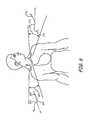
- FIG. 6is a schematic view of catheters in accordance with embodiments of the invention placed in context of a patient's body.
- FIG. 6illustrates one application of a system in accordance with embodiments of the invention that includes a right subclavian vein method of approaching the left pericardiophrenic vein at 160 .
- a system in accordance with embodiments of the inventionthat includes a right subclavian vein method of approaching the left pericardiophrenic vein at 160 .
- access to the left pericardiophrenic veinis obtained utilizing a shape 162 of the catheter 160 .
- the catheter 160enters the right subclavian vein and passes through the right brachiocephalic vein.
- the shape 162then transitions into the left brachiocephalic vein in order to gain access to the left pericardiophrenic vein.
- the shape 162comprises two pre-formed curves 164 and 166 which facilitate access and provide stability of the catheter 160 during deployment of the lead.
- Curves 164 and 166engage the venous walls in the subclavian veins in order to provide adequate support for the delivery of the lead.
- the curved tip of the cathetermay work in conjunction with the curves 164 and 166 to provide a stable catheter platform for delivering the lead.
- a 90 degree hook 141FIG. 4
- Curve 164may help facilitate crossover from the right brachiocephalic vein to the left brachiocephalic vein as the catheter is advanced. The curve may then “nest” at the junction of the right and left brachiocephalic veins to further stabilize the catheter as the lead or wire is advanced into the vein.
- Veins that allow blood to return to the heart in an upward flow relative to gravitymay have venous valves within them. These valves can restrict access by leads, catheters, and other intravenous devices, especially in smaller bore veins. Methods in accordance with embodiments of the invention allow for cannulation of these veins through the use of a guide wire 115 , catheter 130 , and dilator 150 .
- a catheter in accordance with embodiments of the inventionis deployed proximate a target location in the venous system. A guide wire is fed through the catheter to a target location. If possible, a lead in accordance with embodiments of the invention is fed over the wire until it is implanted at the desired location.
- a dilator in accordance with embodiments of the inventioncan be fed over the wire instead of the lead and can push through the valves or tortuosity to create a path through which the lead can be implanted. The dilator is then removed from the catheter and the lead is implanted through the pathway created by the dilator.
- a left subclavian vein method of approaching the left pericardiophrenic veinis also illustrated in FIG. 6 at 170 .
- the left subclavian vein methodoperates similarly to the right subclavian method, except that the shape 172 of the catheter 170 utilizing the left subclavian method comprises two curves 174 and 176 where 176 engages the junction of the left internal jugular vein and the left brachiocephalic vein while the catheter is engaged at the ostium of the pericardiophrenic vein to support the lead's delivery.
- the hook 141 of an embodiment configured for a left subclavian approach to the left pericardiophrenic vein through the left brachiocephalic veinmay be on the order of 130 degrees, for example. Other hook angles may occur to those of skill in the art upon reading this disclosure.
Landscapes
- Health & Medical Sciences (AREA)
- Life Sciences & Earth Sciences (AREA)
- Heart & Thoracic Surgery (AREA)
- Veterinary Medicine (AREA)
- Animal Behavior & Ethology (AREA)
- Public Health (AREA)
- Biomedical Technology (AREA)
- Engineering & Computer Science (AREA)
- General Health & Medical Sciences (AREA)
- Pulmonology (AREA)
- Hematology (AREA)
- Anesthesiology (AREA)
- Biophysics (AREA)
- Vascular Medicine (AREA)
- Cardiology (AREA)
- Nuclear Medicine, Radiotherapy & Molecular Imaging (AREA)
- Radiology & Medical Imaging (AREA)
- Electrotherapy Devices (AREA)
- Media Introduction/Drainage Providing Device (AREA)
Abstract
Description
Claims (9)
Priority Applications (4)
| Application Number | Priority Date | Filing Date | Title |
|---|---|---|---|
| US13/049,520US9744349B2 (en) | 2011-02-10 | 2011-03-16 | Medical lead and implantation |
| US15/663,022US10821280B2 (en) | 2011-02-10 | 2017-07-28 | Medical lead and implantation |
| US17/085,847US12233258B2 (en) | 2011-02-10 | 2020-10-30 | Medical lead and implantation |
| US19/026,363US20250242155A1 (en) | 2011-02-10 | 2025-01-17 | Medical lead and implantation |
Applications Claiming Priority (2)
| Application Number | Priority Date | Filing Date | Title |
|---|---|---|---|
| US201161441559P | 2011-02-10 | 2011-02-10 | |
| US13/049,520US9744349B2 (en) | 2011-02-10 | 2011-03-16 | Medical lead and implantation |
Related Child Applications (1)
| Application Number | Title | Priority Date | Filing Date |
|---|---|---|---|
| US15/663,022ContinuationUS10821280B2 (en) | 2011-02-10 | 2017-07-28 | Medical lead and implantation |
Publications (2)
| Publication Number | Publication Date |
|---|---|
| US20120209284A1 US20120209284A1 (en) | 2012-08-16 |
| US9744349B2true US9744349B2 (en) | 2017-08-29 |
Family
ID=46637467
Family Applications (4)
| Application Number | Title | Priority Date | Filing Date |
|---|---|---|---|
| US13/049,520Active2031-06-16US9744349B2 (en) | 2011-02-10 | 2011-03-16 | Medical lead and implantation |
| US15/663,022Active2031-07-18US10821280B2 (en) | 2011-02-10 | 2017-07-28 | Medical lead and implantation |
| US17/085,847Active2033-09-18US12233258B2 (en) | 2011-02-10 | 2020-10-30 | Medical lead and implantation |
| US19/026,363PendingUS20250242155A1 (en) | 2011-02-10 | 2025-01-17 | Medical lead and implantation |
Family Applications After (3)
| Application Number | Title | Priority Date | Filing Date |
|---|---|---|---|
| US15/663,022Active2031-07-18US10821280B2 (en) | 2011-02-10 | 2017-07-28 | Medical lead and implantation |
| US17/085,847Active2033-09-18US12233258B2 (en) | 2011-02-10 | 2020-10-30 | Medical lead and implantation |
| US19/026,363PendingUS20250242155A1 (en) | 2011-02-10 | 2025-01-17 | Medical lead and implantation |
Country Status (1)
| Country | Link |
|---|---|
| US (4) | US9744349B2 (en) |
Cited By (8)
| Publication number | Priority date | Publication date | Assignee | Title |
|---|---|---|---|---|
| US10792499B2 (en) | 2007-01-29 | 2020-10-06 | Lungpacer Medical Inc. | Transvascular nerve stimulation apparatus and methods |
| US10821280B2 (en) | 2011-02-10 | 2020-11-03 | Respicardia, Inc. | Medical lead and implantation |
| US10926087B2 (en) | 2017-08-02 | 2021-02-23 | Lungpacer Medical Inc. | Systems and methods for intravascular catheter positioning and/or nerve stimulation |
| US11357979B2 (en) | 2019-05-16 | 2022-06-14 | Lungpacer Medical Inc. | Systems and methods for sensing and stimulation |
| US11357985B2 (en) | 2012-06-21 | 2022-06-14 | Lungpacer Medical Inc. | Transvascular diaphragm pacing systems and methods of use |
| US11771900B2 (en) | 2019-06-12 | 2023-10-03 | Lungpacer Medical Inc. | Circuitry for medical stimulation systems |
| US11883658B2 (en) | 2017-06-30 | 2024-01-30 | Lungpacer Medical Inc. | Devices and methods for prevention, moderation, and/or treatment of cognitive injury |
| US12414709B2 (en) | 2021-02-11 | 2025-09-16 | Zoll Respicardia, Inc. | Monitoring system and user interface for monitoring implantable disordered breathing treatment systems |
Families Citing this family (11)
| Publication number | Priority date | Publication date | Assignee | Title |
|---|---|---|---|---|
| IN2014MN01970A (en) | 2012-03-05 | 2015-07-03 | Univ Fraser Simon | |
| CN105873630B (en) | 2013-11-22 | 2020-01-03 | 隆佩瑟尔医疗公司 | Device and method for assisted respiration by transvascular nerve stimulation |
| AU2015208640B2 (en) | 2014-01-21 | 2020-02-20 | Lungpacer Medical Inc. | Systems and related methods for optimization of multi-electrode nerve pacing |
| US20150352330A1 (en)* | 2014-06-09 | 2015-12-10 | Boston Scientific Scimed, Inc. | Deliver assist device for guide catheter |
| SG10201602007WA (en)* | 2015-04-20 | 2016-11-29 | Biotronik Se & Co Kg | Implantable curved shaping part for externally shaping an implantable electrode line or a catheter |
| US10293164B2 (en) | 2017-05-26 | 2019-05-21 | Lungpacer Medical Inc. | Apparatus and methods for assisted breathing by transvascular nerve stimulation |
| US10940308B2 (en) | 2017-08-04 | 2021-03-09 | Lungpacer Medical Inc. | Systems and methods for trans-esophageal sympathetic ganglion recruitment |
| US20190175908A1 (en) | 2017-12-11 | 2019-06-13 | Lungpacer Medical Inc. | Systems and methods for strengthening a respiratory muscle |
| US10470797B1 (en) | 2018-07-17 | 2019-11-12 | SlipStream, LLC | Systems and methods for vascular access |
| EP4548964A1 (en) | 2018-11-08 | 2025-05-07 | Lungpacer Medical Inc. | Stimulation systems and related user interfaces |
| AU2023356902A1 (en)* | 2022-10-04 | 2025-04-17 | Cook Medical Technologies Llc | Variable durometer dilator for intravascular access devices |
Citations (65)
| Publication number | Priority date | Publication date | Assignee | Title |
|---|---|---|---|---|
| US4169479A (en) | 1977-02-24 | 1979-10-02 | Rudolph Muto | Elongated, tapered flexible front guide for electrical catheters and method of use |
| US4306562A (en)* | 1978-12-01 | 1981-12-22 | Cook, Inc. | Tear apart cannula |
| US4471777A (en)* | 1983-03-30 | 1984-09-18 | Mccorkle Jr Charles E | Endocardial lead extraction apparatus and method |
| USRE31855E (en)* | 1978-12-01 | 1985-03-26 | Cook, Inc. | Tear apart cannula |
| US4846812A (en)* | 1988-03-22 | 1989-07-11 | Menlo Care, Inc. | Softening catheter |
| US5184621A (en) | 1991-05-29 | 1993-02-09 | C. R. Bard, Inc. | Steerable guidewire having electrodes for measuring vessel cross-section and blood flow |
| US5312355A (en)* | 1991-07-09 | 1994-05-17 | H L Medical Inventions, Inc. | Splittable hemostatic valve and sheath and the method for using the same |
| US5423876A (en)* | 1993-12-09 | 1995-06-13 | Medtronic, Inc. | Intramuscular lead having improved insertion |
| US5489225A (en)* | 1993-12-16 | 1996-02-06 | Ventritex, Inc. | Electrical terminal with a collet grip for a defibrillator |
| US5531781A (en) | 1993-11-02 | 1996-07-02 | Alferness; Clifton A. | Implantable lead having a steering distal guide tip |
| US5755766A (en)* | 1997-01-24 | 1998-05-26 | Cardiac Pacemakers, Inc. | Open-ended intravenous cardiac lead |
| US5769875A (en)* | 1994-09-06 | 1998-06-23 | Case Western Reserve University | Functional neuromusclar stimulation system |
| US5871528A (en)* | 1996-06-28 | 1999-02-16 | Medtronic, Inc. | Temporary bipolar heart wire |
| US6321123B1 (en)* | 1999-03-08 | 2001-11-20 | Medtronic Inc. | J-shaped coronary sinus lead |
| US20020049485A1 (en)* | 1999-11-29 | 2002-04-25 | Medtronic, Inc. | Medical electrical lead having bending stiffnesses which increase in the distal direction |
| US6456863B1 (en) | 1997-10-01 | 2002-09-24 | Ep Technologies, Inc. | Molded catheter distal end assembly and process for the manufacture thereof |
| US20020165535A1 (en) | 2000-05-16 | 2002-11-07 | Lesh Michael D. | Deflectable tip catheter with guidewire tracking mechanism |
| US20030028232A1 (en)* | 2000-01-20 | 2003-02-06 | Medtronic, Inc. | Method of lmplanting a medical electrical lead |
| US20030181967A1 (en)* | 2000-10-04 | 2003-09-25 | Fysh Dadd | Combination stylet and straightening coating for a cochlear implant electrode array |
| US6662055B1 (en)* | 1999-12-17 | 2003-12-09 | Impulse Dynamics Nv | Multi-electrode intravascular lead |
| US6714823B1 (en)* | 1998-04-29 | 2004-03-30 | Emory University | Cardiac pacing lead and delivery system |
| US20040064024A1 (en)* | 2002-09-30 | 2004-04-01 | Sommer John L. | Cardiac vein lead and guide catheter |
| US20040236396A1 (en)* | 1999-04-05 | 2004-11-25 | Coe Michael Sean | Lead locking device and method |
| US20050054989A1 (en)* | 2001-01-09 | 2005-03-10 | Rex Medical, L.P. | Dialysis catheter |
| US20050070986A1 (en)* | 2003-09-30 | 2005-03-31 | Tockman Bruce A. | Guide wire stylet |
| US6944506B1 (en)* | 2002-06-25 | 2005-09-13 | Pacesetter, Inc. | Stylet feature for resisting perforation of an implantable lead |
| US20050256503A1 (en)* | 2002-05-07 | 2005-11-17 | Cardiac Pacemakers, Inc. | Tapered catheter delivery system |
| US20050288759A1 (en) | 2003-08-08 | 2005-12-29 | Jones Timothy S | Method and apparatus for implanting an electrical stimulation lead using a flexible introducer |
| US20060135962A1 (en)* | 2004-09-09 | 2006-06-22 | Kick George F | Expandable trans-septal sheath |
| US20060142783A1 (en)* | 1998-02-03 | 2006-06-29 | Lewis Brian D | Methods and systems for treating ischemia |
| US20060247750A1 (en)* | 2005-04-28 | 2006-11-02 | Seifert Kevin R | Guide catheters for accessing cardiac sites |
| US20070043390A1 (en)* | 2005-08-18 | 2007-02-22 | Salviac Limited | Delivery catheter |
| US20070055334A1 (en)* | 2005-08-23 | 2007-03-08 | Cardiac Pacemakers, Inc. | Cardiac lead and stylet assembly |
| US20070088417A1 (en)* | 2005-10-06 | 2007-04-19 | Schouenborg Jens O | Electrode bundle |
| US20070282412A1 (en)* | 2006-06-02 | 2007-12-06 | Cardiac Pacemakers, Inc. | Medical electrical lead with deployable fixation features |
| US20080009929A1 (en)* | 2003-08-29 | 2008-01-10 | Medtronic, Inc. | Percutaneous flat lead introducer |
| US20080071341A1 (en)* | 2005-04-15 | 2008-03-20 | Cook Vascular Incorporated | Tip for lead extraction device |
| US20080188867A1 (en)* | 2007-02-05 | 2008-08-07 | Ignagni Anthony R | Removable intramuscular electrode |
| US20080243081A1 (en)* | 2007-03-30 | 2008-10-02 | Onset Medical, Inc. | Expandable trans-septal sheath |
| US20090036947A1 (en)* | 2006-11-17 | 2009-02-05 | Westlund Randy W | Transvenous Phrenic Nerve Stimulation System |
| US7628801B2 (en) | 2000-08-30 | 2009-12-08 | Cardiac Pacemakers, Inc. | Coronary vein leads having an atraumatic tip and method therefor |
| US7647124B2 (en)* | 2005-11-15 | 2010-01-12 | Medtronic, Inc. | Delivery catheter |
| US7647115B2 (en) | 2002-04-08 | 2010-01-12 | Ardian, Inc. | Renal nerve stimulation method and apparatus for treatment of patients |
| US20100076534A1 (en)* | 2006-10-25 | 2010-03-25 | William Alan Mock | Malleable needle having a plurality of electrodes for facilitating implantation of stimulation lead and method of implanting an electrical stimulation lead |
| US7699809B2 (en)* | 2006-12-14 | 2010-04-20 | Urmey William F | Catheter positioning system |
| US7729782B2 (en)* | 2005-11-15 | 2010-06-01 | Medtronic, Inc. | Delivery catheter |
| US20100152748A1 (en)* | 2008-12-12 | 2010-06-17 | E-Pacing, Inc. | Devices, Systems, and Methods Providing Body Lumen Access |
| US7747334B2 (en)* | 2006-03-23 | 2010-06-29 | Cardiac Pacemakers, Inc. | Left ventricular lead shapes |
| US7747323B2 (en) | 2004-06-08 | 2010-06-29 | Cardiac Pacemakers, Inc. | Adaptive baroreflex stimulation therapy for disordered breathing |
| US7787946B2 (en) | 2003-08-18 | 2010-08-31 | Cardiac Pacemakers, Inc. | Patient monitoring, diagnosis, and/or therapy systems and methods |
| US7792591B2 (en)* | 2005-06-09 | 2010-09-07 | Medtronic, Inc. | Introducer for therapy delivery elements |
| US20100268312A1 (en)* | 2001-12-10 | 2010-10-21 | Gordon Wallace | Control of shape of an implantable electrode array |
| US20110009934A1 (en)* | 2009-07-13 | 2011-01-13 | Pacesetter, Inc. | Implantable medical lead having passive lock mechanical body terminations |
| US20110160825A1 (en)* | 2009-12-30 | 2011-06-30 | Joshua Haarer | Implantable leads with a conductor coil having two or more sections |
| US20110160830A1 (en)* | 2009-12-31 | 2011-06-30 | Morris Kimberly A | Implantable leads with an axial reinforcement member |
| US20110160820A1 (en)* | 2009-12-30 | 2011-06-30 | Jackson Timothy R | Variable stiffness multi-lumen lead body for an impantable lead |
| US20110160822A1 (en)* | 2009-12-30 | 2011-06-30 | Jackson Timothy R | Implantable lead electrode with asymetrically distributed current density and methods for imparting current density directionality in lead electrodes |
| US20110301593A1 (en)* | 2007-01-25 | 2011-12-08 | Warsaw Orthopedic, Inc. | Surgical navigational and neuromonitoring instrument |
| US8086314B1 (en) | 2000-09-27 | 2011-12-27 | Cvrx, Inc. | Devices and methods for cardiovascular reflex control |
| US8090451B2 (en)* | 2006-03-30 | 2012-01-03 | Medtronic Inc. | Transvenous active fixation lead system |
| US20120130397A1 (en)* | 2010-11-19 | 2012-05-24 | Reddy G Shantanu | Multi-function lead implant tool |
| US20120130269A1 (en)* | 2010-11-19 | 2012-05-24 | Neural Pathways, Llc | Integrated nerve stimulation and skin marking device and methods of using same |
| US8200336B2 (en) | 2003-10-15 | 2012-06-12 | Rmx, Llc | System and method for diaphragm stimulation |
| US8244378B2 (en)* | 2007-01-30 | 2012-08-14 | Cardiac Pacemakers, Inc. | Spiral configurations for intravascular lead stability |
| US8280513B2 (en) | 2006-12-22 | 2012-10-02 | Rmx, Llc | Device and method to treat flow limitations |
Family Cites Families (23)
| Publication number | Priority date | Publication date | Assignee | Title |
|---|---|---|---|---|
| US5445625A (en)* | 1991-01-23 | 1995-08-29 | Voda; Jan | Angioplasty guide catheter |
| US5125904B1 (en) | 1991-07-09 | 1996-11-19 | Hl Medical Inventions Inc | Splittable hemostatic valve sheath and the method for using the same |
| US5308342A (en)* | 1991-08-07 | 1994-05-03 | Target Therapeutics, Inc. | Variable stiffness catheter |
| US5437632A (en)* | 1993-06-02 | 1995-08-01 | Target Therapeutics, Inc. | Variable stiffness balloon catheter |
| US6277107B1 (en)* | 1993-08-13 | 2001-08-21 | Daig Corporation | Guiding introducer for introducing medical devices into the coronary sinus and process for using same |
| US5639276A (en)* | 1994-09-23 | 1997-06-17 | Rapid Development Systems, Inc. | Device for use in right ventricular placement and method for using same |
| US5836311A (en)* | 1995-09-20 | 1998-11-17 | Medtronic, Inc. | Method and apparatus for temporarily immobilizing a local area of tissue |
| US5772693A (en)* | 1996-02-09 | 1998-06-30 | Cardiac Control Systems, Inc. | Single preformed catheter configuration for a dual-chamber pacemaker system |
| US6022336A (en)* | 1996-05-20 | 2000-02-08 | Percusurge, Inc. | Catheter system for emboli containment |
| US6132417A (en)* | 1997-08-22 | 2000-10-17 | Scheider/Namic | Right coronary artery catheter |
| US6638268B2 (en)* | 2000-04-07 | 2003-10-28 | Imran K. Niazi | Catheter to cannulate the coronary sinus |
| US6887229B1 (en)* | 2000-11-07 | 2005-05-03 | Pressure Products Medical Supplies Inc. | Method and apparatus for insertion of elongate instruments within a body cavity |
| US6869414B2 (en)* | 2002-03-22 | 2005-03-22 | Cardiac Pacemakers, Inc. | Pre-shaped catheter with proximal articulation and pre-formed distal end |
| US7462184B2 (en)* | 2002-05-06 | 2008-12-09 | Pressure Products Medical Supplies Inc. | Introducer for accessing the coronary sinus of a heart |
| US7115134B2 (en)* | 2002-07-22 | 2006-10-03 | Chambers Technology, Llc. | Catheter with flexible tip and shape retention |
| US7993351B2 (en)* | 2002-07-24 | 2011-08-09 | Pressure Products Medical Supplies, Inc. | Telescopic introducer with a compound curvature for inducing alignment and method of using the same |
| US8361067B2 (en)* | 2002-09-30 | 2013-01-29 | Relievant Medsystems, Inc. | Methods of therapeutically heating a vertebral body to treat back pain |
| US20050010237A1 (en)* | 2003-06-09 | 2005-01-13 | Niazi Imran K. | Catheter to cannulate coronary sinus branches |
| US20060074403A1 (en)* | 2004-09-29 | 2006-04-06 | Nasser Rafiee | Curved catheter comprising a solid-walled metal tube with varying stiffness |
| US20090082756A1 (en)* | 2007-09-25 | 2009-03-26 | Vasundhara Vidyarthi | Transradial coronary catheter |
| JP5154692B2 (en)* | 2008-04-15 | 2013-02-27 | カーディアック ペースメイカーズ, インコーポレイテッド | His bundle stimulation system |
| US20090312786A1 (en)* | 2008-06-12 | 2009-12-17 | Terumo Medical Corporation | Guide Sheath Dilator And Method Of Using The Same |
| US9744349B2 (en) | 2011-02-10 | 2017-08-29 | Respicardia, Inc. | Medical lead and implantation |
- 2011
- 2011-03-16USUS13/049,520patent/US9744349B2/enactiveActive
- 2017
- 2017-07-28USUS15/663,022patent/US10821280B2/enactiveActive
- 2020
- 2020-10-30USUS17/085,847patent/US12233258B2/enactiveActive
- 2025
- 2025-01-17USUS19/026,363patent/US20250242155A1/enactivePending
Patent Citations (71)
| Publication number | Priority date | Publication date | Assignee | Title |
|---|---|---|---|---|
| US4169479A (en) | 1977-02-24 | 1979-10-02 | Rudolph Muto | Elongated, tapered flexible front guide for electrical catheters and method of use |
| US4306562A (en)* | 1978-12-01 | 1981-12-22 | Cook, Inc. | Tear apart cannula |
| USRE31855E (en)* | 1978-12-01 | 1985-03-26 | Cook, Inc. | Tear apart cannula |
| USRE31855F1 (en)* | 1978-12-01 | 1986-08-19 | Tear apart cannula | |
| US4471777A (en)* | 1983-03-30 | 1984-09-18 | Mccorkle Jr Charles E | Endocardial lead extraction apparatus and method |
| US4846812A (en)* | 1988-03-22 | 1989-07-11 | Menlo Care, Inc. | Softening catheter |
| US5184621A (en) | 1991-05-29 | 1993-02-09 | C. R. Bard, Inc. | Steerable guidewire having electrodes for measuring vessel cross-section and blood flow |
| US5312355A (en)* | 1991-07-09 | 1994-05-17 | H L Medical Inventions, Inc. | Splittable hemostatic valve and sheath and the method for using the same |
| US5531781A (en) | 1993-11-02 | 1996-07-02 | Alferness; Clifton A. | Implantable lead having a steering distal guide tip |
| US5423876A (en)* | 1993-12-09 | 1995-06-13 | Medtronic, Inc. | Intramuscular lead having improved insertion |
| US5489225A (en)* | 1993-12-16 | 1996-02-06 | Ventritex, Inc. | Electrical terminal with a collet grip for a defibrillator |
| US5769875A (en)* | 1994-09-06 | 1998-06-23 | Case Western Reserve University | Functional neuromusclar stimulation system |
| US5871528A (en)* | 1996-06-28 | 1999-02-16 | Medtronic, Inc. | Temporary bipolar heart wire |
| US5755766A (en)* | 1997-01-24 | 1998-05-26 | Cardiac Pacemakers, Inc. | Open-ended intravenous cardiac lead |
| US6456863B1 (en) | 1997-10-01 | 2002-09-24 | Ep Technologies, Inc. | Molded catheter distal end assembly and process for the manufacture thereof |
| US20060142783A1 (en)* | 1998-02-03 | 2006-06-29 | Lewis Brian D | Methods and systems for treating ischemia |
| US6714823B1 (en)* | 1998-04-29 | 2004-03-30 | Emory University | Cardiac pacing lead and delivery system |
| US6321123B1 (en)* | 1999-03-08 | 2001-11-20 | Medtronic Inc. | J-shaped coronary sinus lead |
| US20040236396A1 (en)* | 1999-04-05 | 2004-11-25 | Coe Michael Sean | Lead locking device and method |
| US20020049485A1 (en)* | 1999-11-29 | 2002-04-25 | Medtronic, Inc. | Medical electrical lead having bending stiffnesses which increase in the distal direction |
| US6662055B1 (en)* | 1999-12-17 | 2003-12-09 | Impulse Dynamics Nv | Multi-electrode intravascular lead |
| US20030028232A1 (en)* | 2000-01-20 | 2003-02-06 | Medtronic, Inc. | Method of lmplanting a medical electrical lead |
| US20020165535A1 (en) | 2000-05-16 | 2002-11-07 | Lesh Michael D. | Deflectable tip catheter with guidewire tracking mechanism |
| US7628801B2 (en) | 2000-08-30 | 2009-12-08 | Cardiac Pacemakers, Inc. | Coronary vein leads having an atraumatic tip and method therefor |
| US8290595B2 (en) | 2000-09-27 | 2012-10-16 | Cvrx, Inc. | Method and apparatus for stimulation of baroreceptors in pulmonary artery |
| US8086314B1 (en) | 2000-09-27 | 2011-12-27 | Cvrx, Inc. | Devices and methods for cardiovascular reflex control |
| US20030181967A1 (en)* | 2000-10-04 | 2003-09-25 | Fysh Dadd | Combination stylet and straightening coating for a cochlear implant electrode array |
| US20050054989A1 (en)* | 2001-01-09 | 2005-03-10 | Rex Medical, L.P. | Dialysis catheter |
| US20100268312A1 (en)* | 2001-12-10 | 2010-10-21 | Gordon Wallace | Control of shape of an implantable electrode array |
| US7647115B2 (en) | 2002-04-08 | 2010-01-12 | Ardian, Inc. | Renal nerve stimulation method and apparatus for treatment of patients |
| US8131372B2 (en) | 2002-04-08 | 2012-03-06 | Ardian, Inc. | Renal nerve stimulation method for treatment of patients |
| US20050256503A1 (en)* | 2002-05-07 | 2005-11-17 | Cardiac Pacemakers, Inc. | Tapered catheter delivery system |
| US6944506B1 (en)* | 2002-06-25 | 2005-09-13 | Pacesetter, Inc. | Stylet feature for resisting perforation of an implantable lead |
| US20040064024A1 (en)* | 2002-09-30 | 2004-04-01 | Sommer John L. | Cardiac vein lead and guide catheter |
| US8463401B2 (en) | 2003-08-08 | 2013-06-11 | Advanced Neuromodulation Systems, Inc. | Apparatus for implanting an electrical stimulation lead |
| US20050288759A1 (en) | 2003-08-08 | 2005-12-29 | Jones Timothy S | Method and apparatus for implanting an electrical stimulation lead using a flexible introducer |
| US7787946B2 (en) | 2003-08-18 | 2010-08-31 | Cardiac Pacemakers, Inc. | Patient monitoring, diagnosis, and/or therapy systems and methods |
| US20080009929A1 (en)* | 2003-08-29 | 2008-01-10 | Medtronic, Inc. | Percutaneous flat lead introducer |
| US20050070986A1 (en)* | 2003-09-30 | 2005-03-31 | Tockman Bruce A. | Guide wire stylet |
| US8348941B2 (en) | 2003-10-15 | 2013-01-08 | Rmx, Llc | Demand-based system for treating breathing disorders |
| US8200336B2 (en) | 2003-10-15 | 2012-06-12 | Rmx, Llc | System and method for diaphragm stimulation |
| US8255056B2 (en) | 2003-10-15 | 2012-08-28 | Rmx, Llc | Breathing disorder and precursor predictor and therapy delivery device and method |
| US7747323B2 (en) | 2004-06-08 | 2010-06-29 | Cardiac Pacemakers, Inc. | Adaptive baroreflex stimulation therapy for disordered breathing |
| US20060135962A1 (en)* | 2004-09-09 | 2006-06-22 | Kick George F | Expandable trans-septal sheath |
| US20080071341A1 (en)* | 2005-04-15 | 2008-03-20 | Cook Vascular Incorporated | Tip for lead extraction device |
| US20060247750A1 (en)* | 2005-04-28 | 2006-11-02 | Seifert Kevin R | Guide catheters for accessing cardiac sites |
| US7792591B2 (en)* | 2005-06-09 | 2010-09-07 | Medtronic, Inc. | Introducer for therapy delivery elements |
| US20070043390A1 (en)* | 2005-08-18 | 2007-02-22 | Salviac Limited | Delivery catheter |
| US20070055334A1 (en)* | 2005-08-23 | 2007-03-08 | Cardiac Pacemakers, Inc. | Cardiac lead and stylet assembly |
| US20070088417A1 (en)* | 2005-10-06 | 2007-04-19 | Schouenborg Jens O | Electrode bundle |
| US7729782B2 (en)* | 2005-11-15 | 2010-06-01 | Medtronic, Inc. | Delivery catheter |
| US7647124B2 (en)* | 2005-11-15 | 2010-01-12 | Medtronic, Inc. | Delivery catheter |
| US7747334B2 (en)* | 2006-03-23 | 2010-06-29 | Cardiac Pacemakers, Inc. | Left ventricular lead shapes |
| US8090451B2 (en)* | 2006-03-30 | 2012-01-03 | Medtronic Inc. | Transvenous active fixation lead system |
| US20070282412A1 (en)* | 2006-06-02 | 2007-12-06 | Cardiac Pacemakers, Inc. | Medical electrical lead with deployable fixation features |
| US20100076534A1 (en)* | 2006-10-25 | 2010-03-25 | William Alan Mock | Malleable needle having a plurality of electrodes for facilitating implantation of stimulation lead and method of implanting an electrical stimulation lead |
| US20090036947A1 (en)* | 2006-11-17 | 2009-02-05 | Westlund Randy W | Transvenous Phrenic Nerve Stimulation System |
| US7699809B2 (en)* | 2006-12-14 | 2010-04-20 | Urmey William F | Catheter positioning system |
| US8280513B2 (en) | 2006-12-22 | 2012-10-02 | Rmx, Llc | Device and method to treat flow limitations |
| US20110301593A1 (en)* | 2007-01-25 | 2011-12-08 | Warsaw Orthopedic, Inc. | Surgical navigational and neuromonitoring instrument |
| US8244378B2 (en)* | 2007-01-30 | 2012-08-14 | Cardiac Pacemakers, Inc. | Spiral configurations for intravascular lead stability |
| US20080188867A1 (en)* | 2007-02-05 | 2008-08-07 | Ignagni Anthony R | Removable intramuscular electrode |
| US20080243081A1 (en)* | 2007-03-30 | 2008-10-02 | Onset Medical, Inc. | Expandable trans-septal sheath |
| US20100152748A1 (en)* | 2008-12-12 | 2010-06-17 | E-Pacing, Inc. | Devices, Systems, and Methods Providing Body Lumen Access |
| US20110009934A1 (en)* | 2009-07-13 | 2011-01-13 | Pacesetter, Inc. | Implantable medical lead having passive lock mechanical body terminations |
| US20110160825A1 (en)* | 2009-12-30 | 2011-06-30 | Joshua Haarer | Implantable leads with a conductor coil having two or more sections |
| US20110160820A1 (en)* | 2009-12-30 | 2011-06-30 | Jackson Timothy R | Variable stiffness multi-lumen lead body for an impantable lead |
| US20110160822A1 (en)* | 2009-12-30 | 2011-06-30 | Jackson Timothy R | Implantable lead electrode with asymetrically distributed current density and methods for imparting current density directionality in lead electrodes |
| US20110160830A1 (en)* | 2009-12-31 | 2011-06-30 | Morris Kimberly A | Implantable leads with an axial reinforcement member |
| US20120130269A1 (en)* | 2010-11-19 | 2012-05-24 | Neural Pathways, Llc | Integrated nerve stimulation and skin marking device and methods of using same |
| US20120130397A1 (en)* | 2010-11-19 | 2012-05-24 | Reddy G Shantanu | Multi-function lead implant tool |
Cited By (12)
| Publication number | Priority date | Publication date | Assignee | Title |
|---|---|---|---|---|
| US10792499B2 (en) | 2007-01-29 | 2020-10-06 | Lungpacer Medical Inc. | Transvascular nerve stimulation apparatus and methods |
| US11027130B2 (en) | 2007-01-29 | 2021-06-08 | Lungpacer Medical Inc. | Transvascular nerve stimulation apparatus and methods |
| US12268877B2 (en) | 2007-01-29 | 2025-04-08 | Lungpacer Medical Inc. | Transvascular nerve stimulation apparatus and methods |
| US10821280B2 (en) | 2011-02-10 | 2020-11-03 | Respicardia, Inc. | Medical lead and implantation |
| US12233258B2 (en) | 2011-02-10 | 2025-02-25 | Zoll Respicardia, Inc. | Medical lead and implantation |
| US11357985B2 (en) | 2012-06-21 | 2022-06-14 | Lungpacer Medical Inc. | Transvascular diaphragm pacing systems and methods of use |
| US11883658B2 (en) | 2017-06-30 | 2024-01-30 | Lungpacer Medical Inc. | Devices and methods for prevention, moderation, and/or treatment of cognitive injury |
| US10926087B2 (en) | 2017-08-02 | 2021-02-23 | Lungpacer Medical Inc. | Systems and methods for intravascular catheter positioning and/or nerve stimulation |
| US11357979B2 (en) | 2019-05-16 | 2022-06-14 | Lungpacer Medical Inc. | Systems and methods for sensing and stimulation |
| US11771900B2 (en) | 2019-06-12 | 2023-10-03 | Lungpacer Medical Inc. | Circuitry for medical stimulation systems |
| US12403312B2 (en) | 2019-06-12 | 2025-09-02 | Lungpacer Medical Inc. | Circuitry for medical stimulation systems |
| US12414709B2 (en) | 2021-02-11 | 2025-09-16 | Zoll Respicardia, Inc. | Monitoring system and user interface for monitoring implantable disordered breathing treatment systems |
Also Published As
| Publication number | Publication date |
|---|---|
| US20250242155A1 (en) | 2025-07-31 |
| US20120209284A1 (en) | 2012-08-16 |
| US20210046303A1 (en) | 2021-02-18 |
| US10821280B2 (en) | 2020-11-03 |
| US20170326354A1 (en) | 2017-11-16 |
| US12233258B2 (en) | 2025-02-25 |
Similar Documents
| Publication | Publication Date | Title |
|---|---|---|
| US20250242155A1 (en) | Medical lead and implantation | |
| US20250001136A1 (en) | Rapid Insertion Integrated Catheter and Method of Using an Integrated Catheter | |
| US11154324B2 (en) | Methods and devices for puncturing tissue | |
| US6562049B1 (en) | Medical introducer apparatus | |
| US9302083B2 (en) | Carotid sheath with entry and tracking rapid exchange dilators and method of use | |
| US7771401B2 (en) | Selective renal cannulation and infusion systems and methods | |
| AU2013207563B2 (en) | Guidewire with highly flexible tip | |
| US9302078B2 (en) | Systems and methods for gaining access around an implanted medical device | |
| US8100883B1 (en) | Right-side coronary sinus lead delivery catheter | |
| US20080183255A1 (en) | Side port lead delivery system | |
| US7041097B1 (en) | System and method for accessing the coronary sinus | |
| EP4122523A1 (en) | Trimmable catheter including distal portion stability features | |
| WO2022271999A1 (en) | Enhanced guide extension system for the efficient delivery of leads | |
| US10773087B1 (en) | Lead delivery for His-bundle pacing | |
| US20090082756A1 (en) | Transradial coronary catheter | |
| WO2008021997A3 (en) | Apparatus and methods for delivering transvenous leads | |
| US20190001103A1 (en) | Guidewire access sleeve | |
| US20120035585A1 (en) | Tapered venous access introducer | |
| US20090275918A1 (en) | Pancreatic delivery catheter | |
| WO2021003056A3 (en) | Remote access vascular and soft tissue tunneling dilator systems and methods of use | |
| US10213584B2 (en) | Method and apparatus for guiding a catheter | |
| US20110190784A1 (en) | Catheter with removable shaping skeleton and methods of using and making same | |
| US9272085B2 (en) | Method of introducing a catheter | |
| US6468252B1 (en) | Clamp for vascular access device | |
| US20140107576A1 (en) | Apparatus for left-side installation of tunneled vascular catheters |
Legal Events
| Date | Code | Title | Description |
|---|---|---|---|
| AS | Assignment | Owner name:RESPICARDIA, INC., MINNESOTA Free format text:ASSIGNMENT OF ASSIGNORS INTEREST;ASSIGNORS:WESTLUND, RANDY, MR.;LYNN, MARK, MR.;REEL/FRAME:029273/0878 Effective date:20121107 | |
| STCF | Information on status: patent grant | Free format text:PATENTED CASE | |
| AS | Assignment | Owner name:CANTOR FITZGERALD SECURITIES, AS AGENT, NEW YORK Free format text:SECURITY INTEREST;ASSIGNOR:RESPICARDIA, INC.;REEL/FRAME:044298/0370 Effective date:20171204 Owner name:ZOLL MEDICAL CORPORATION, MASSACHUSETTS Free format text:SECURITY INTEREST;ASSIGNOR:RESPICARDIA, INC.;REEL/FRAME:044298/0216 Effective date:20171204 | |
| MAFP | Maintenance fee payment | Free format text:PAYMENT OF MAINTENANCE FEE, 4TH YR, SMALL ENTITY (ORIGINAL EVENT CODE: M2551); ENTITY STATUS OF PATENT OWNER: SMALL ENTITY Year of fee payment:4 | |
| AS | Assignment | Owner name:ZOLL RESPICARDIA, INC., MASSACHUSETTS Free format text:CHANGE OF NAME;ASSIGNOR:RESPICARDIA, INC.;REEL/FRAME:056267/0334 Effective date:20210506 | |
| AS | Assignment | Owner name:ZOLL RESPICARDIA, INC., MINNESOTA Free format text:CORRECTIVE ASSIGNMENT TO CORRECT THE ASSIGNEE ADDRESS PREVIOUSLY RECORDED AT REEL: 056267 FRAME: 0334. ASSIGNOR(S) HEREBY CONFIRMS THE CHANGE OF NAME;ASSIGNOR:RESPICARDIA, INC.;REEL/FRAME:056366/0506 Effective date:20210506 | |
| FEPP | Fee payment procedure | Free format text:ENTITY STATUS SET TO UNDISCOUNTED (ORIGINAL EVENT CODE: BIG.); ENTITY STATUS OF PATENT OWNER: LARGE ENTITY | |
| MAFP | Maintenance fee payment | Free format text:PAYMENT OF MAINTENANCE FEE, 8TH YEAR, LARGE ENTITY (ORIGINAL EVENT CODE: M1552); ENTITY STATUS OF PATENT OWNER: LARGE ENTITY Year of fee payment:8 |