US9742593B2 - Systems and methods for adaptively-tuned digital self-interference cancellation - Google Patents
Systems and methods for adaptively-tuned digital self-interference cancellationDownload PDFInfo
- Publication number
- US9742593B2 US9742593B2US15/362,289US201615362289AUS9742593B2US 9742593 B2US9742593 B2US 9742593B2US 201615362289 AUS201615362289 AUS 201615362289AUS 9742593 B2US9742593 B2US 9742593B2
- Authority
- US
- United States
- Prior art keywords
- signal
- digital
- self
- interference
- transform
- Prior art date
- Legal status (The legal status is an assumption and is not a legal conclusion. Google has not performed a legal analysis and makes no representation as to the accuracy of the status listed.)
- Active
Links
- 238000000034methodMethods0.000titleclaimsabstractdescription101
- 239000011159matrix materialSubstances0.000claimsabstractdescription40
- 230000004044responseEffects0.000claimsabstractdescription37
- 230000001131transforming effectEffects0.000claimsabstractdescription7
- 238000004891communicationMethods0.000claimsdescription59
- 239000002131composite materialSubstances0.000claimsdescription26
- 230000003068static effectEffects0.000claimsdescription20
- 230000008859changeEffects0.000claimsdescription5
- 230000000977initiatory effectEffects0.000claims1
- 230000006870functionEffects0.000description64
- 238000006243chemical reactionMethods0.000description26
- 230000003044adaptive effectEffects0.000description25
- 238000005070samplingMethods0.000description25
- 230000005540biological transmissionEffects0.000description17
- 238000001914filtrationMethods0.000description16
- 230000000694effectsEffects0.000description14
- 230000008569processEffects0.000description14
- 238000010586diagramMethods0.000description12
- 230000007613environmental effectEffects0.000description12
- 238000012545processingMethods0.000description12
- 238000009499grossingMethods0.000description11
- 230000008878couplingEffects0.000description9
- 238000010168coupling processMethods0.000description9
- 238000005859coupling reactionMethods0.000description9
- 230000001965increasing effectEffects0.000description9
- 238000013178mathematical modelMethods0.000description9
- 230000000875corresponding effectEffects0.000description8
- 230000004048modificationEffects0.000description8
- 238000012986modificationMethods0.000description8
- 230000009466transformationEffects0.000description5
- 238000012935AveragingMethods0.000description4
- 238000004458analytical methodMethods0.000description4
- 238000013528artificial neural networkMethods0.000description4
- 238000011478gradient descent methodMethods0.000description4
- 230000010355oscillationEffects0.000description4
- 238000001228spectrumMethods0.000description4
- 238000012360testing methodMethods0.000description4
- 230000008901benefitEffects0.000description3
- 238000004364calculation methodMethods0.000description3
- 229920005994diacetyl cellulosePolymers0.000description3
- 238000005259measurementMethods0.000description3
- 238000003062neural network modelMethods0.000description3
- 230000003595spectral effectEffects0.000description3
- 235000015429Mirabilis expansaNutrition0.000description2
- 244000294411Mirabilis expansaSpecies0.000description2
- 241001168730SimoSpecies0.000description2
- 230000006978adaptationEffects0.000description2
- 230000002457bidirectional effectEffects0.000description2
- 230000002596correlated effectEffects0.000description2
- 239000013078crystalSubstances0.000description2
- 230000007423decreaseEffects0.000description2
- 230000003111delayed effectEffects0.000description2
- 230000001419dependent effectEffects0.000description2
- 238000001514detection methodMethods0.000description2
- 230000002708enhancing effectEffects0.000description2
- 230000007274generation of a signal involved in cell-cell signalingEffects0.000description2
- 238000010801machine learningMethods0.000description2
- 235000013536misoNutrition0.000description2
- 238000012544monitoring processMethods0.000description2
- 230000010363phase shiftEffects0.000description2
- 238000007781pre-processingMethods0.000description2
- 230000009467reductionEffects0.000description2
- 230000003321amplificationEffects0.000description1
- 239000003990capacitorSubstances0.000description1
- 230000015556catabolic processEffects0.000description1
- 230000001413cellular effectEffects0.000description1
- 238000012937correctionMethods0.000description1
- 125000004122cyclic groupChemical group0.000description1
- 238000000354decomposition reactionMethods0.000description1
- 230000003247decreasing effectEffects0.000description1
- 238000006731degradation reactionMethods0.000description1
- 238000003708edge detectionMethods0.000description1
- 238000005516engineering processMethods0.000description1
- 230000007246mechanismEffects0.000description1
- 230000003446memory effectEffects0.000description1
- 238000003199nucleic acid amplification methodMethods0.000description1
- 230000003287optical effectEffects0.000description1
- 238000005457optimizationMethods0.000description1
- 238000012805post-processingMethods0.000description1
- 238000000926separation methodMethods0.000description1
- 230000008054signal transmissionEffects0.000description1
- 238000004800variational methodMethods0.000description1
Images


Classifications
- H—ELECTRICITY
- H04—ELECTRIC COMMUNICATION TECHNIQUE
- H04L—TRANSMISSION OF DIGITAL INFORMATION, e.g. TELEGRAPHIC COMMUNICATION
- H04L27/00—Modulated-carrier systems
- H04L27/26—Systems using multi-frequency codes
- H04L27/2601—Multicarrier modulation systems
- H04L27/2647—Arrangements specific to the receiver only
- H04L27/2649—Demodulators
- H04L27/265—Fourier transform demodulators, e.g. fast Fourier transform [FFT] or discrete Fourier transform [DFT] demodulators
- H04L27/2651—Modification of fast Fourier transform [FFT] or discrete Fourier transform [DFT] demodulators for performance improvement
- H—ELECTRICITY
- H04—ELECTRIC COMMUNICATION TECHNIQUE
- H04L—TRANSMISSION OF DIGITAL INFORMATION, e.g. TELEGRAPHIC COMMUNICATION
- H04L25/00—Baseband systems
- H04L25/02—Details ; arrangements for supplying electrical power along data transmission lines
- H04L25/03—Shaping networks in transmitter or receiver, e.g. adaptive shaping networks
- H04L25/03006—Arrangements for removing intersymbol interference
- H—ELECTRICITY
- H04—ELECTRIC COMMUNICATION TECHNIQUE
- H04B—TRANSMISSION
- H04B1/00—Details of transmission systems, not covered by a single one of groups H04B3/00 - H04B13/00; Details of transmission systems not characterised by the medium used for transmission
- H04B1/38—Transceivers, i.e. devices in which transmitter and receiver form a structural unit and in which at least one part is used for functions of transmitting and receiving
- H04B1/40—Circuits
- H04B1/50—Circuits using different frequencies for the two directions of communication
- H04B1/52—Hybrid arrangements, i.e. arrangements for transition from single-path two-direction transmission to single-direction transmission on each of two paths or vice versa
- H04B1/525—Hybrid arrangements, i.e. arrangements for transition from single-path two-direction transmission to single-direction transmission on each of two paths or vice versa with means for reducing leakage of transmitter signal into the receiver
- H—ELECTRICITY
- H04—ELECTRIC COMMUNICATION TECHNIQUE
- H04B—TRANSMISSION
- H04B1/00—Details of transmission systems, not covered by a single one of groups H04B3/00 - H04B13/00; Details of transmission systems not characterised by the medium used for transmission
- H04B1/38—Transceivers, i.e. devices in which transmitter and receiver form a structural unit and in which at least one part is used for functions of transmitting and receiving
- H04B1/40—Circuits
- H04B1/54—Circuits using the same frequency for two directions of communication
- H04B1/56—Circuits using the same frequency for two directions of communication with provision for simultaneous communication in two directions
- H—ELECTRICITY
- H04—ELECTRIC COMMUNICATION TECHNIQUE
- H04L—TRANSMISSION OF DIGITAL INFORMATION, e.g. TELEGRAPHIC COMMUNICATION
- H04L25/00—Baseband systems
- H04L25/02—Details ; arrangements for supplying electrical power along data transmission lines
- H04L25/0202—Channel estimation
- H04L25/0204—Channel estimation of multiple channels
- H—ELECTRICITY
- H04—ELECTRIC COMMUNICATION TECHNIQUE
- H04L—TRANSMISSION OF DIGITAL INFORMATION, e.g. TELEGRAPHIC COMMUNICATION
- H04L25/00—Baseband systems
- H04L25/02—Details ; arrangements for supplying electrical power along data transmission lines
- H04L25/03—Shaping networks in transmitter or receiver, e.g. adaptive shaping networks
- H04L25/03006—Arrangements for removing intersymbol interference
- H04L25/03178—Arrangements involving sequence estimation techniques
- H04L25/03248—Arrangements for operating in conjunction with other apparatus
- H04L25/0328—Arrangements for operating in conjunction with other apparatus with interference cancellation circuitry
- H—ELECTRICITY
- H04—ELECTRIC COMMUNICATION TECHNIQUE
- H04L—TRANSMISSION OF DIGITAL INFORMATION, e.g. TELEGRAPHIC COMMUNICATION
- H04L27/00—Modulated-carrier systems
- H04L27/26—Systems using multi-frequency codes
- H04L27/2601—Multicarrier modulation systems
- H04L27/2647—Arrangements specific to the receiver only
- H04L27/2649—Demodulators
- H04L27/265—Fourier transform demodulators, e.g. fast Fourier transform [FFT] or discrete Fourier transform [DFT] demodulators
- H—ELECTRICITY
- H04—ELECTRIC COMMUNICATION TECHNIQUE
- H04L—TRANSMISSION OF DIGITAL INFORMATION, e.g. TELEGRAPHIC COMMUNICATION
- H04L47/00—Traffic control in data switching networks
- H04L47/10—Flow control; Congestion control
- H04L47/29—Flow control; Congestion control using a combination of thresholds
- H—ELECTRICITY
- H04—ELECTRIC COMMUNICATION TECHNIQUE
- H04L—TRANSMISSION OF DIGITAL INFORMATION, e.g. TELEGRAPHIC COMMUNICATION
- H04L5/00—Arrangements affording multiple use of the transmission path
- H04L5/14—Two-way operation using the same type of signal, i.e. duplex
- H—ELECTRICITY
- H04—ELECTRIC COMMUNICATION TECHNIQUE
- H04L—TRANSMISSION OF DIGITAL INFORMATION, e.g. TELEGRAPHIC COMMUNICATION
- H04L5/00—Arrangements affording multiple use of the transmission path
- H04L5/14—Two-way operation using the same type of signal, i.e. duplex
- H04L5/1461—Suppression of signals in the return path, i.e. bidirectional control circuits
Definitions
- This inventionrelates generally to the wireless communications field, and more specifically to new and useful systems and methods for adaptively-tuned digital self-interference cancellation.
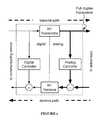
- FIG. 1is a schematic representation of a full-duplex transceiver
- FIG. 2is a diagram representation of a system of a preferred embodiment
- FIG. 3is a diagram representation of a receiver of a system of a preferred embodiment
- FIG. 4is a diagram representation of a transmitter of a system of a preferred embodiment
- FIGS. 5A and 5Bare diagram representations of signal couplers of a system of a preferred embodiment
- FIG. 6is a diagram representation of a system of a preferred embodiment
- FIG. 7is a diagram representation of a component generation system of a system of a preferred embodiment
- FIG. 8is a diagram representation of a digital self-interference canceller of a system of a preferred embodiment
- FIG. 9is a diagram representation of an ADC of a system of a preferred embodiment.
- FIG. 10is a diagram representation of a DAC of a system of a preferred embodiment
- FIG. 11is a diagram representation of a system of a preferred embodiment
- FIG. 12is a diagram representation of a self-interference canceller of a system of a preferred embodiment
- FIG. 13is a diagram representation of a self-interference canceller of a system of a preferred embodiment
- FIG. 14is a chart representation of a method of a preferred embodiment
- FIG. 15is an example representation of a method of a preferred embodiment
- FIG. 16is an example representation of magnitude response smoothing of a method of a preferred embodiment
- FIG. 17is an example representation of magnitude response smoothing of a method of a preferred embodiment.
- FIG. 18is an example representation of channel representation processing of a method of a preferred embodiment.
- Wireless communications systemshave revolutionized the way the world communicates, and the rapid growth of communication using such systems has provided increased economic and educational opportunity across all regions and industries.
- the wireless spectrum required for communicationis a finite resource, and the rapid growth in wireless communications has also made the availability of this resource ever scarcer.
- spectral efficiencyhas become increasingly important to wireless communications systems.
- full-duplex wireless communications systemshave substantial value to the wireless communications field, such systems have been known to face challenges due to self-interference; because reception and transmission occur at the same time on the same channel, the received signal at a full-duplex transceiver may include undesired signal components from the signal being transmitted from that transceiver. As a result, full-duplex wireless communications systems often include analog and/or digital self-interference cancellation circuits to reduce self-interference.
- Full-duplex transceiverspreferably sample transmission output as baseband digital signals, intermediate frequency (IF) analog signals, or as radio-frequency (RF) analog signals, but full-duplex transceivers may additionally or alternatively sample transmission output in any suitable manner.
- This sampled transmission outputmay be used by full-duplex transceivers to remove interference from received wireless communications data (e.g., as RF/IF analog signals or baseband digital signals).
- an analog self-interference cancellation systemis paired with a digital self-interference cancellation system. The analog cancellation system removes a first portion of self-interference by summing delayed and scaled versions of the RF transmit signal to create an RF self-interference cancellation signal, which is then subtracted from the RF receive signal.
- the analog cancellation systemmay perform similar tasks at an intermediate frequency. After the RF (or IF) receive signal has the RF/IF self-interference cancellation signal subtracted, it passes through an analog-to-digital converter of the receiver (and becomes a digital receive signal). After this stage, a digital self-interference cancellation signal (created by transforming a digital transmit signal) is then subtracted from the digital receive signal.
- Full-duplex transceiversoften include tuning systems that adjust tunable parameters of the analog self-interference cancellation system in order to adapt the analog self-interference cancellation signal to changing self-interference conditions.
- full-duplex transceiversmay similarly include tuning systems that alter the transform configuration of digital self-interference cancellation systems for the same purpose.
- the systems and methods described hereinincrease tuning performance of full-duplex transceivers as shown in FIG. 1 (and other applicable systems) by performing digital self-interference canceller tuning, thus allowing for increased effectiveness in self-interference cancellation.
- Other applicable systemsinclude active sensing systems (e.g., RADAR), wired communications systems, wireless communications systems, and/or any other suitable system, including communications systems where transmit and receive bands are close in frequency, but not overlapping.
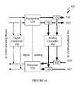
- a system 100 for adaptively-tuned digital self-interference cancellationincludes a receiver 110 , a transmitter 120 , a signal coupler 130 , a digital self-interference canceller 140 , analog-to-digital converters (ADCs) 150 and 151 , a digital-to-analog converter (DAC) 152 , and an analog canceller 160 .
- ADCsanalog-to-digital converters
- DACdigital-to-analog converter
- the system 100functions to increase the performance of self-interference cancellation by performing digital self-interference canceller tuning intelligently based on both transmit signal input and residue signal input. Transmit signal input is used to identify components of a transmit signal likely to be reflected in received self-interference, while residue signal input is used to determine the effects of self-interference cancellation.
- the system 100is preferably implemented using both digital and analog circuitry.
- Digital circuitryis preferably implemented using a general-purpose processor, a digital signal processor, an application specific integrated circuit (ASIC), a field programmable gate array (FPGA) and/or any suitable processor(s) or circuit(s).
- Analog circuitryis preferably implemented using analog integrated circuits (ICs) but may additionally or alternatively be implemented using discrete components (e.g., capacitors, resistors, transistors), wires, transmission lines, waveguides, digital components, mixed-signal components, or any other suitable components.
- the system 100preferably includes memory to store configuration data, but may additionally or alternatively be configured using externally stored configuration data or in any suitable manner.
- the receiver 110functions to receive analog receive signals transmitted over a communications link (e.g., a wireless channel, a coaxial cable).
- a communications linke.g., a wireless channel, a coaxial cable.
- the receiver 110preferably converts analog receive signals into digital receive signals for processing by a communications system, but may additionally or alternatively not convert analog receive signals (passing them through directly without conversion).
- the receiver 110is preferably a radio-frequency (RF) receiver, but may additionally or alternatively be any suitable receiver.
- RFradio-frequency
- the receiver 110is preferably coupled to the communications link by a duplexer-coupled RF antenna, but may additionally or alternatively be coupled to the communications link in any suitable manner. Some examples of alternative couplings include coupling via one or more dedicated receive antennas. In another alternative coupling, the receiver 110 may be coupled to the communications link by a circulator-coupled RF antenna.
- the receiver 110preferably includes an analog-to-digital converter (ADC) 111 and a frequency downconverter 112 , as shown in FIG. 3 .
- the receiver 110may additionally include a low-noise amplifier 113 .
- the receiver 110may additionally or alternatively include amplifiers, filters, signal processors and/or any other suitable components.
- the receiver 110includes only analog processing circuitry (e.g., amplifiers, filters, attenuators, delayers). The receiver may function to scale, shift, and/or otherwise modify the receive signal.
- the downconverter 112functions to downconvert the analog receive signal from RF (or any other suitable frequency) to a baseband analog receive signal
- the analog-to-digital converter (ADC) 111functions to convert the baseband analog receive signal to a digital receive signal.
- the ADC 111may be any suitable analog-to-digital converter; e.g., a direct-conversion ADC, a flash ADC, a successive-approximation ADC, a ramp-compare ADC, a Wilkinson ADC, an integrating ADC, a delta-encoded ADC, a time-interleaved ADC, or any other suitable type of ADC.
- a direct-conversion ADCe.g., a flash ADC, a successive-approximation ADC, a ramp-compare ADC, a Wilkinson ADC, an integrating ADC, a delta-encoded ADC, a time-interleaved ADC, or any other suitable type of ADC.
- the frequency downconverter 112functions to downconvert the carrier frequency of the analog receive signal to baseband, preparing it for conversion to a digital receive signal.
- the downconverter 112preferably accomplishes signal downconversion using heterodyning methods, but may additionally or alternatively use any suitable downconversion methods.
- the downconverter 112preferably includes a local oscillator (LO), a mixer, and a baseband filter.
- the local oscillatorfunctions to provide a frequency shift signal to the mixer; the mixer combines the frequency shift signal and the analog receive signal to create (usually two) frequency shifted signals, one of which is the baseband signal, and the baseband filter rejects signals other than the baseband analog receive signal.
- the local oscillatoris preferably a digital crystal variable-frequency oscillator (VFO) but may additionally or alternatively be an analog VFO or any other suitable type of oscillator.
- VFOdigital crystal variable-frequency oscillator
- the local oscillatorpreferably has a tunable oscillation frequency but may additionally or alternatively have a static oscillation frequency.
- the mixeris preferably an active mixer, but may additionally or alternatively be a passive mixer.
- the mixermay comprise discrete components, analog ICs, digital ICs, and/or any other suitable components.
- the mixerpreferably functions to combine two or more electrical input signals into one or more composite outputs, where each output includes some characteristics of at least two input signals.
- the baseband filteris preferably a lowpass filter with a tunable low-pass frequency. Additionally or alternatively, the baseband filter may be a lowpass filter with a set low-pass frequency, or any other suitable type of filter.
- the baseband filteris preferably a passive filter, but may additionally or alternatively be an active filter.
- the baseband filteris preferably implemented with analog circuit components, but may additionally or alternatively be digitally implemented.
- the transmitter 120functions to transmit signals of the communications system over a communications link to a second communications system.
- the transmitter 120preferably converts digital transmit signals into analog transmit signals.
- the transmitter 120is preferably a radio-frequency (RF) transmitter, but may additionally or alternatively be any suitable transmitter.
- RFradio-frequency
- the transmitter 120is preferably coupled to the communications link by a duplexer-coupled RF antenna, but may additionally or alternatively be coupled to the communications link in any suitable manner. Some examples of alternative couplings include coupling via one or more dedicated transmit antennas. In another alternative coupling, the transmitter 120 may be coupled to the communications link by a duplexer-coupled RF antenna.
- the transmitter 120preferably includes a digital-to-analog converter (DAC) 121 and a frequency upconverter 122 , as shown in FIG. 4 .
- the transmitter 120may additionally include a power amplifier 123 .
- the transmitter 120may additionally or alternatively include amplifiers, filters, signal processors and/or any other suitable components.
- the transmitter 120may function to scale, shift, and/or otherwise modify the transmit signal.
- the digital-to-analog converter (DAC) 121functions to convert the digital transmit signal to a baseband analog transmit signal
- the upconverter 122functions to upconvert the baseband analog transmit signal from baseband to RF (or any other intended transmission frequency).
- the DAC 121may be any suitable digital-to-analog converter; e.g., a pulse-width modulator, an oversampling DAC, a binary-weighted DAC, an R-2R ladder DAC, a cyclic DAC, a thermometer-coded DAC, or a hybrid DAC.
- a pulse-width modulatore.g., a pulse-width modulator, an oversampling DAC, a binary-weighted DAC, an R-2R ladder DAC, a cyclic DAC, a thermometer-coded DAC, or a hybrid DAC.
- the frequency upconverter 122functions to upconvert the carrier frequency of the baseband analog transmit signal to a radio frequency, preparing it for transmission over the communications link.
- the upconverter 122preferably accomplishes signal upconversion using heterodyning methods, but may additionally or alternatively use any suitable upconversion methods.
- the upconverter 122preferably includes a local oscillator (LO), a mixer, and an RF filter.
- the local oscillatorfunctions to provide a frequency shift signal to the mixer; the mixer combines the frequency shift signal and the baseband analog transmit signal to create (usually two) frequency shifted signals, one of which is the RF analog transmit signal, and the RF filter rejects signals other than the RF analog transmit signal.
- the local oscillatoris preferably a digital crystal variable-frequency oscillator (VFO) but may additionally or alternatively be an analog VFO or any other suitable type of oscillator.
- VFOdigital crystal variable-frequency oscillator
- the local oscillatorpreferably has a tunable oscillation frequency but may additionally or alternatively have a static oscillation frequency.
- the mixeris preferably an active mixer, but may additionally or alternatively be a passive mixer.
- the mixermay comprise discrete components, analog ICs, digital ICs, and/or any other suitable components.
- the mixerpreferably functions to combine two or more electrical input signals into one or more composite outputs, where each output includes some characteristics of at least two input signals.
- the RF filteris preferably a bandpass filter centered around a tunable radio frequency. Additionally or alternatively, the RF filter may be a bandpass filter centered around a set radio frequency, or any other suitable type of filter.
- the RF filteris preferably a passive filter, but may additionally or alternatively be an active filter.
- the RF filteris preferably implemented with analog circuit components, but may additionally or alternatively be digitally implemented.
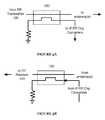
- the signal coupler 130functions to allow signals to be split and/or joined.
- the signal coupler 130may be used to provide a sample of the analog transmit signal for the digital canceller 140 and/or analog cancellers 160 , as shown in FIG. 5A ; that is, the signal coupler 130 may serve as a transmit coupler.
- the signal coupler 130may also be used to combine one or more analog self-interference cancellation signals (from analog/digital cancellers) with the analog receive signal, as shown in FIG. 5B ; that is, the signal coupler 130 may serve as a receive coupler.
- the signal coupler 130may be used for any other purpose.
- a signal coupler 130may be used to provide a sample of a residue signal (in this case, an analog receive signal that has already been combined with analog and digitally-sourced self-interference cancellation signals) to the digital canceller 140 .
- the signal coupler 130is preferably directly coupled to the transmitter 120 , but may additionally or alternatively be coupled indirectly to the transmitter 120 and/or be coupled to another suitable RF transmission source.
- the signal coupler 130preferably has at least two outputs; one coupled to antenna(e) (directly or indirectly) and another coupled to one or more of the digital canceller 140 and the analog canceller 160 .
- the signal coupler 130preferably routes the majority of input power to the antenna(e) output port, but may additionally or alternatively route power in any suitable manner (e.g., routing the majority of power to other output ports).
- the signal coupler 130may have any number of input and output ports, including bidirectional input/output ports.
- the receive coupler 130is preferably coupled directly to the receiver 110 , but may additionally or alternatively be coupled indirectly to the receiver 110 and/or be coupled to another suitable RF receiver.
- the signal coupler 130preferably has at least two inputs, one coupled to antenna(e) of the full-duplex radio (directly or indirectly) and another coupled to one or more of the digital canceller 140 and the analog canceller 160 .
- the signal coupler 130preferably couples the majority of power from both input ports to the receiver output port; this coupling preferably results in the receiver output port outputting a sum of one or more self-interference cancellation signals (generated by 140 / 160 and the RF receive signal (received at the antenna(e)). Additionally or alternatively, the signal coupler 130 may couple or route power in any suitable manner.
- the signal coupler 130may have any number of input and output ports, including bidirectional input/output ports.
- the signal coupler 130is preferably a short section directional transmission line coupler, but may additionally or alternatively be any power divider, power combiner, directional coupler, or other type of signal splitter.
- the signal coupler 130is preferably a passive coupler, but may additionally or alternatively be an active coupler (for instance, including power amplifiers).
- the signal coupler 130may comprise a coupled transmission line coupler, a branch-line coupler, a Lange coupler, a Wilkinson power divider, a hybrid coupler, a hybrid ring coupler, a multiple output divider, a waveguide directional coupler, a waveguide power coupler, a hybrid transformer coupler, a cross-connected transformer coupler, a resistive tee, and/or a resistive bridge hybrid coupler.
- the output ports of the signal coupler 130are preferably phase-shifted by ninety degrees, but may additionally or alternatively be in phase or phase shifted by a different amount.
- the system 100preferably includes at least two signal couplers 130 (e.g., a transmit and a receive coupler); these signal couplers 130 preferably connect to a single antenna through a duplexer or circulator, but may additionally or alternatively connect to multiple antennae.
- the transmit coupler and receive couplerconnect to two separate antennae (e.g., a transmit antenna and a receive antenna); in another example, the transmit coupler and receive coupler both connect to the same two antennae.
- the transmit coupler and receive couplermay additionally or alternatively connect to any suitable RF transmit and RF receive sources (e.g., an RF signal transmitted solely over coaxial cable). There may additionally or alternatively be filters, power amplifiers, and/or any other RF signal modifying components between the couplers 130 and antennae.
- the digital self-interference canceller 140functions to produce a digital self-interference cancellation signal from a digital transmit signal.
- the digital self-interference cancellation signalis preferably converted to an analog self-interference cancellation signal (by the DAC 152 ) and combined with one or more analog self-interference cancellation signals to further reduce self-interference present in the RF receive signal at the receiver 110 .
- the digital self-interference cancellation signalmay be combined with a digital receive signal (e.g., after the receiver 110 ).
- the digital self-interference canceller 140preferably samples the RF transmit signal of the transmitter 120 using the ADC 150 (additionally or alternatively, the canceller 140 may sample the digital transmit signal or any other suitable transmit signal) and transforms the sampled and converted RF (or IF) transmit signal to a digital self-interference signal based on a digital transform configuration.
- the digital transform configurationpreferably includes settings that dictate how the digital self-interference canceller 140 transforms the digital transmit signal to a digital self-interference signal (e.g. coefficients of a generalized memory polynomial used to transform the transmit signal to a self-interference signal).
- digital self-interference canceller 140may be coupled to any transmit and/or receive signals (either as input to the canceller or as outputs of the canceller), as described in U.S. patent application Ser. No. 14/569,354, the entirety of which is incorporated by this reference.
- the digital self-interference cancellermay take as input an RF-sourced intermediate frequency (IF) transmit signal (e.g., the transmit signal is converted to RF by the transmitter 120 , then downconverted to IF by a downcoverter, then passed through the ADC 150 to the digital canceller 140 ) or may output at IF (e.g., the digital self-interference cancellation signal is converted to a digitally-sourced IF self-interference cancellation signal, and is then combined with an IF self-interference cancellation signal at IF, before the combined self-interference cancellation signal is converted to RF and combined with an RF receive signal).
- IFintermediate frequency
- the digital self-interference canceller 140may be implemented using a general-purpose processor, a digital signal processor, an application specific integrated circuit (ASIC), a field programmable gate array (FPGA) and/or any suitable processor(s) or circuit(s).
- the digital self-interference canceller 140preferably includes memory to store configuration data, but may additionally or alternatively be configured using externally stored configuration data or in any suitable manner.
- the digital self-interference canceller 140includes a component generation system 141 , a multi-rate filter 142 , and a transform adaptor 143 , as shown in FIG. 6 .
- the digital self-interference canceller 140may additionally or alternatively include a blocker filter 144 , and/or a filter inverter 145 .
- the component generation system 141functions to generate a set of signal components from the sampled transmit signal (or signals) that may be used by the multi-rate filter 142 to generate a self-interference cancellation signal.
- the component generation system 141preferably samples digital transmit signals corresponding to a native sampling rate. Additionally or alternatively, the component generation system 141 may sample a subset of digital transmit signal data; for instance, if a digital transmit signal has a native sample rate of 40 MHz, the component generation system 141 might discard every other sample, corresponding to a sample rate of 20 MHz (while the RF transmitter may still receive all samples, corresponding to a sample rate of 40 MHz). The component generation system 141 may additionally or alternatively interpolate digital transmit signals to increase or decrease sampling rate. In one instance, the component generation system 141 modifies the sampling rate of a digital transmit signal to match a sampling rate of an RF receiver of a full-duplex radio.
- the component generation system 141may perform pre-processing to prepare sampled digital transmit signals for component generation.
- the component generation system 141may include various operators for pre-processing such as scaling, shifting, and/or otherwise modifying the digital transmit signals.
- the component generation system 141modifies sampled digital transmit signals by removing information unlikely to substantially affect the output of the multi-rate filter 142 . This may include, for instance, dropping samples if the samples do not represent a change above some change threshold from previous samples. As another example, if digital transmit signals correspond to a particular amplitude of an output analog signal, only digital signal data corresponding to an amplitude above some amplitude threshold (or a power above some power threshold) may be passed to the multi-rate filter 142 .
- the component generation system 141may additionally or alternatively combine the signals in any suitable way or may select one signal over another. For instance, the component generation system 141 may pass the average of the two signals to the multi-rate filter 142 . As another example, the component generation system 141 may prefer an RF-sourced digital transmit signal (e.g., from the ADC 150 ) over the transmit-path digital transmit signal (e.g., sampled before conversion by the transmitter 120 ) above a certain transmitter power, and vice versa at or below that transmitter power. The selection and combination of the two (or more) signals may be dependent on any suitable condition.
- the component generation system 141may additionally or alternatively combine the signals in any suitable way or may select one signal over another. For instance, the component generation system 141 may pass the average of the two signals to the multi-rate filter 142 . As another example, the component generation system 141 may prefer an RF-sourced digital transmit signal (e.g., from the ADC 150 ) over the transmit-path digital transmit signal (e.g., sampled before conversion
- the component generation system 141preferably generates a set of signal components that may be weighted and combined by the multi-rate filter 142 in order to generate a self-interference cancellation signal.
- the self-interference cancellation signalis based upon a hypothesized contribution of self-interference to a received signal.
- Self-interference contributionsmay result from a variety of sources, including components in both RF receivers and RF transmitters of full-duplex radios (e.g., mixers, power amplifiers, ADCs, DACs, etc.). Further, self-interference contributions may vary randomly, or with environmental or input conditions (e.g. transmission power, ambient temperature, etc.).
- the component generation system 141preferably generates transmit signal components according to mathematical models adapted to model self-interference contributions of the RF transmitter, RF receiver, and/or other sources.
- the component generation system 141preferably generates a set of signal components intended to be used with a specific mathematical model (e.g., generalized memory polynomial (GMP) models, Volterra models, and Wiener-Hammerstein models); additionally or alternatively, the signal component generation system may generate a set of signal components usable with multiple mathematical models.
- GMPgeneralized memory polynomial
- Signal component setsmay additionally or alternatively be chosen based on comparisons of sampled digital transmit signals to received signals (from the receive path or any other suitable source). Signal component sets may be generated from previously known models or may be created using neural network and/or machine learning techniques.
- GMP modelFor example, a general form of a GMP model is as follows:
- a component generation system 141configured to generate a signal component set according to this GMP model might generate signal components by output order; for example, a first signal component might simply be x[n], while a second signal component may be x[n]
- Such a signal component setmight have N components (the Nth component represented as x[n]
- the bandwidth of terms of order kare generally k times larger than the bandwidth of the input signal; for example, if an input signal x[n] has a bandwidth of 40 MHz, the third order terms (e.g., x[n]
- the input signalis preferably sampled at a sampling rate of 120 MHz (three times more than an initial Nyquist sampling rate of 40 MHz). As the number of terms increase, so does the ability to model non-linear self-interference effects, but so also does the minimum sampling rate to avoid aliasing.
- the RF transmittermay also have to match this increased sampling rate in order to subtract non-linear digital interference signals from received signals. For example, if a GMP model uses 7 th order terms, for the same 40 MHz transmit signal the RF receiver may have to sample the received signal at a rate of 280 MHz to avoid aliasing issues (and likewise, the transmit signal may have to be sampled at the same rate).
- the component generation system 141addresses these issues by separating components at least partially according to component order (e.g., one component containing x[n] terms, another component containing x[n]
- component ordere.g., one component containing x[n] terms, another component containing x[n]
- the preferred result of this separationis that the sampling rate necessary for each model component to avoid aliasing is known as a function of component order.
- the component generation system 141includes a number of transform paths 1411 , each of which may include an upsampler 1412 , a component generator 1413 , a downsampler 1414 , a signal combiner 1415 , and/or an anti-aliasing filter (AAF) 1416 , as shown in FIG. 7 .
- AAFanti-aliasing filter
- the transform path 1411may first upsample the digital transmit signal by passing it to the upsampler 1412 .
- the upsampler 1412functions to increase the number of samples contained within the digital transmit signal in order to reduce aliasing effects. Note that for first order signal components, upsampling may not be necessary.
- the upsampler 1412preferably increases the number of samples contained within a digital transmit signal component according to linear interpolation, but may additionally or alternatively use any suitable method.
- the upsampler 1412upsamples a digital transmit signal component by creating a sequence comprising the original samples separated by L ⁇ 1 zeroes (where L is the upsampling factor) and then passing the new signal through a finite impulse response (FIR) lowpass filter.
- FIRfinite impulse response
- the upsampler 1412creates a sequence comprising the original samples separated from each other by L ⁇ 1 new samples, where each new sample is modeled on how a DAC converts digital samples to an analog signal (e.g. if the output of the DAC is not exactly linear between outputs).
- the upsampler 1412For a transform path 1411 (and component generator 1413 ) of order k, the upsampler 1412 preferably upsamples the digital transmit signal with an upsampling factor of k, but may additionally or alternatively upsample the digital transmit signal by any suitable factor.
- the component generator 1413functions to create the transmit signal component desired for a particular transform path 1411 .
- a signal component generated for order 3 of a GMP modelmight be generated as x[n]
- the component generator 1413preferably generates signal components of a single order only, but may additionally or alternatively generate components of multiple orders (e.g., x[n]
- the component generator 1413preferably generates signal components according to a generalized memory polynomial (GMP) model, Volterra model, Wiener-Hammerstein model, or neural network model, but may additionally or alternatively use a part or whole of any suitable model or combination of models.
- GMPgeneralized memory polynomial
- the component generator 1413may simply pass a copy of a sampled transmit signal unmodified; this may be considered functionally equivalent to a component generator 1413 not being explicitly included for that particular transform path 1411 . This may be alternatively referred to as a first order component generator.
- the downsampler 1414functions to reduce the number of samples contained within a signal component generated by a component generator 1413 .
- the downsampler 1414preferably downsamples signal components by simply removing signals at a particular interval (e.g., throwing away every other sample to halve the number of samples) but may additionally or alternatively downsample signal components by any suitable method.
- the downsampler 1414preferably downsamples signal components to match the sampling rate of the received digital baseband signal, but may additionally or alternatively downsample signal components to any suitable sampling rate.
- sampling rates of transform path 1411 inputs and outputsneed not necessarily be equal to each other; likewise, sampling rates across transform paths 1411 need not necessarily be equal.
- the system 100preferably includes performing self-interference cancellation at multiple sampling rates (i.e., multi-rate self-interference cancellation).
- the signal combiner 1415functions to allow for combination of signal components.
- the signal combiner 1415may be located at any point within a transform path 1415 and may take any signals as input.
- the component generation system 141does not include any signal combiners 1415 .
- the anti-aliasing filter (AAF) 1416functions to reduce the bandwidth of signal components to prepare the signal components for processing by the multi-rate adaptive filter 142 .
- the AAF 1416is preferably a digitally implemented FIR lowpass filter, but may additionally or alternatively be any suitable type of filter (e.g., infinite impulse response (IIR) filters, fourier-transform based filters).
- the AAF 1416preferably reduces the bandwidth of signal components to match the bandwidth of the digital baseband signal received from the RF transmitter, but may additionally or alternatively function to cap the bandwidth of signal components at any value below the maximum bandwidth of all signal components produced by component generators 1413 .
- the AAF 1416preferably functions to remove non-linear interference signal components not found in the received baseband signal (e.g., if the RF receiver has a corresponding lowpass filter for the baseband analog or digital signals or potentially a corresponding bandpass filter for the RF signal).
- the signal component generation systemincludes one or more frequency shifters 1417 .
- the frequency shifters 1417function to shift the frequency of signal components. Frequency shifting is preferably performed by multiplying the input signal with e ⁇ j ⁇ n where n is the digital sample and ⁇ is a frequency of the band in which self-interference cancellation is to be performed. By shifting the operating frequency of the signal components, interference signals that are present in other frequency bands (e.g., adjacent and/or close to the transmit frequency band) can be estimated and removed from the signal.
- frequency shifters 1417may be located at any point within a transform path 1411 .
- the signal component generation system 141preferably transmits signal components without combining them to the multi-rate adaptive filter 142 (aside from combination resulting from signal combiners 1415 ); additionally or alternatively, signal components may be added, averaged, and/or combined in any suitable manner (e.g. scaling components before adding them and/or combining components multiplicatively).
- the multi-rate adaptive filter 142functions to generate a self-interference cancellation signal from the signal components produced by the component generation system 141 .
- the multi-rate adaptive filter 142may additionally function to perform sampling rate conversions (a la the upsampler 1412 and/or downsampler 1414 ).
- the multi-rate adaptive filter 142preferably generates a self-interference cancellation signal by combining a weighted sum of signal components according to mathematical models adapted to model self-interference contributions of the RF transmitter, RF receiver, and/or other sources.
- mathematical modelsthat may be used by the multi-rate adaptive filter 142 include generalized memory polynomial (GMP) models, Volterra models, and Wiener-Hammerstein models; the multi-rate adaptive filter 142 may additionally or alternatively use any combination or set of models.
- the multi-rate adaptive filter 142may additionally or alternatively use generated mathematical models for modeling self-interference contributions based on comparisons of sampled digital transmit signals to received signals (from the receive path or any other suitable source). These models may be generated from previously known models or may be created using neural network and/or machine learning techniques.
- the multi-rate adaptive filter 142preferably performs self-interference cancellation signal generation according to a transform configuration set dynamically by the transform adaptor 143 (discussed in more detail in sections covering the transform adaptor 143 ). Additionally or alternatively, the multi-rate adaptive filter may combine signal components in any manner in order to generate a self-interference cancellation signal.
- the digital self-interference canceller 140preferably includes a single multi-rate adaptive filter 142 , but may additionally or alternatively include multiple multi-rate adaptive filters 142 .
- the digital self-interference canceller 140may include one multi-rate adaptive filter 142 for linear self-interference cancellation and one for non-linear self-interference cancellation, as shown in FIG. 8 .
- Signal componentsmay be transmitted to multiple multi-rate adaptive filters 142 in any manner (including some or all signal components going to multiple multi-rate adaptive filters 142 ).
- canceller 140includes multiple multi-rate adaptive filters 142 , the output of these filters may be combined in any manner to generate a self-interference cancellation signal.
- the transform adaptor 143functions to set the transform configuration of the multi-rate adaptive filter 142 .
- the transform adaptor 143may additionally or alternatively set configuration of the signal component generation system 141 .
- the transform configurationpreferably includes the type of model or models used by the multi-rate adaptive filter 142 as well as configuration details pertaining to the models (each individual model is a model type paired with a particular set of configuration details). For example, one transform configuration might set the multi-rate adaptive filter 142 to use a GMP model with a particular set of coefficients. If the model type is static, the transform configuration may simply include model configuration details; for example, if the model is always a GMP model, the transform configuration may include only coefficients for the model, and not data designating the model type.
- the transform configurationmay additionally or alternatively include other configuration details related to the signal component generation system 141 and/or the multi-rate adaptive filter 142 .
- the transform adaptor 143may set the number of these transform paths 1411 , which model order their respective component generators 1413 correspond to, the type of filtering used by AAFs 1416 , and/or any other suitable details.
- the transform configurationmay include any details relating to the computation or structure of the signal component generation system 141 and/or the multi-rate adaptive filter 142 .
- Transform configurationsare preferably selected and/or generated by the transform adaptor 143 .
- the transform adaptor 143may set an appropriate transform configuration by selecting from stored static configurations, from generating configurations dynamically, or by any other suitable manner or combination of manners.
- the transform adaptor 143may choose from three static transform configurations based on their applicability to particular signal and/or environmental conditions (the first is appropriate for low transmitter power, the second for medium transmitter power, and the third for high transmitter power).
- the transform adaptor 143may dynamically generate configurations based on signal and/or environmental conditions; the coefficients of a GMP model are set by a formula that takes transmitter power, temperature, and receiver power as input.
- the transform adaptor 143preferably sets transform configurations based on a variety of input data (whether transform configurations are selected from a set of static configurations or generated according to a formula or model).
- Input data used by the transform adaptor 143may include static environmental and system data (e.g. receiver operating characteristics, transmitter operating characteristics, receiver elevation above sea-level), dynamic environmental and system data (e.g. current ambient temperature, current receiver temperature, average transmitter power, ambient humidity), and/or system configuration data (e.g. receiver/transmitter settings), signal data (e.g., digital transmit signal, RF transmit signal, RF receive signal, digital receive signal).
- static environmental and system datae.g. receiver operating characteristics, transmitter operating characteristics, receiver elevation above sea-level
- dynamic environmental and system datae.g. current ambient temperature, current receiver temperature, average transmitter power, ambient humidity
- system configuration datae.g. receiver/transmitter settings
- signal datae.g., digital transmit signal, RF transmit signal, RF receive signal, digital receive signal.
- the transform adaptor 143may additionally or alternatively generate and/or use models based on this input data to set transform configurations; for example, a transmitter manufacturer may give a model to predict internal temperature of the transmitter based on transmitter power, and the transform adaptor 143 may use the output of this model (given transmitter power) as input data for setting transform configurations.
- the transform adaptor 143may set transform configurations at any time, but preferably sets transform configurations in response to either a time threshold or other input data threshold being crossed. For example, the transform adaptor 143 may re-set transform configurations every ten seconds according to changed input data values. As another example, the transform adaptor 143 may re-set transform configurations whenever transmitter power thresholds are crossed (e.g. whenever transmitter power increases by ten percent since the last transform configuration setting, or whenever transmitter power increases over some static value).
- the transform adaptor 143may cooperate with the analog canceller 160 (for instance, setting transform configurations based on data from the analog canceller 160 , coordinating transform configuration setting times with the analog canceller 160 , disabling or modifying operation of the analog canceller 160 to reduce overall self-interference (or for any other suitable reason).
- the transform adapter 143preferably adapts transform configurations and/or transform-configuration-generating algorithms (i.e., algorithms that dynamically generate transform configurations) to reduce self-interference for a given transmit signal and set of system/environmental conditions.
- the transform adapter 143may adapt transform configurations and/or transform-configuration-generating algorithms using analytical methods, online gradient-descent methods (e.g., LMS, RLMS), and/or any other suitable methods.
- Adapting transform configurationspreferably includes changing transform configurations based on learning. In the case of a neural-network model, this might include altering the structure and/or weights of a neural network based on test inputs. In the case of a GMP polynomial model, this might include optimizing GMP polynomial coefficients according to a gradient-descent method.
- the transform adaptor 143may adapt transform configurations based on test input scenarios (e.g. scenarios when the signal received by the RF receiver is known), scenarios where there is no input (e.g. the only signal received at the RF receiver is the signal transmitted by the RF transmitter), or scenarios where the received signal is unknown. In cases where the received signal is an unknown signal, the transform adaptor 143 may adapt transform configurations based on historical received data (e.g. what the signal looked like ten seconds ago) or any other suitable information.
- test input scenariose.g. scenarios when the signal received by the RF receiver is known
- scenarios where there is no inpute.g. the only signal received at the RF receiver is the signal transmitted by the RF transmitter
- scenarios where the received signalis unknown.
- the transform adaptor 143may adapt transform configurations based on historical received data (e.g. what the signal looked like ten seconds ago) or any other suitable information.
- the transform adaptor 143may additionally or alternatively adapt transform configurations based on the content of the transmitted signal; for instance, if the transmitted signal is modulated in a particular way, the transform adaptor 143 may look for that same modulation in the self-interference signal; more specifically, the transform adaptor 143 may adapt transform configurations such that when the self-interference signal is combined with the digital receive signal the remaining modulation (as an indicator of self-interference) is reduced (compared to a previous transform configuration).
- the transform adaptor 143may additionally or alternatively function to set tuning parameters for components outside of the digital self-interference canceller 140 , particularly if those parameters are relevant to digital self-interference canceller performance and/or tuning.
- the blocker filter 144functions to remove unwanted higher order terms in the self-interference cancellation signal generated by the multi-rate adaptive filter 142 .
- the blocker filter 144may be especially useful in reducing unwanted signals not eliminated by the AAFs 1416 .
- the blocker filter 144is preferably a digitally implemented FIR lowpass filter, but may additionally or alternatively be any suitable type of filter (e.g., infinite impulse response (IIR) filters, fourier-transform based filters).
- the blocker filter 144 output sample rateis preferably matched to the output sample rate of the blocker filter present in the RF transmitter 120 (where a blocker filter is standard). If the input sample rate of the blocker filter is not equal to the desired RF transmitter blocker filter sample rate, the blocker filter 144 may perform sample rate conversion in a substantially similar manner to the upsampler 1412 and/or the downsampler 1414 .
- the filter inverter 145preferably functions to remove or reduce the effects of the blocker filter 144 .
- the filter inverter 145is preferably used to remove or reduce the effects of the blocker filter 144 on a residue signal sampled by the transform adaptor 143 (wherein the residue signal refers to the digital transmit signal after combination with the self-interference cancellation signal).
- the filter inverter 145thus enables the transform adaptor 143 to perform optimization based upon the amount of self-interference that would remain without the contribution of the blocker filter (i.e., providing better data to tune upon). Use of the filter inverter 145 may result in substantially faster convergence of transform configuration parameters.
- the filter inverter 145may additionally or alternatively function to remove or reduce the effects of filters or components (other than the blocker filter) on the residue signal sampled by the transform adaptor 143 . In some instances, it may be desirable to remove or reduce effects induced by the receiver of the communications system (or any other elements or components present in the signal path between the multi-rate adaptive filter 142 and the transform adaptor 143 ).
- the filter inverter 145may function to remove or reduce the effects of RF receiver components (e.g., distortions resulting from amplification and/or analog-to-digital conversion).
- the digital self-interference canceller 140may additionally or alternatively include gain/phase compensators that function to modify the gain and phase of either the digital receive signal or the digital self-interference cancellation signal such that the two signals are aligned in gain and phase.
- Gain/phase compensationthus enables the canceller 140 to compensate for gain and/or phase error induced by the receive chain (or other sources).
- Gain/phase correction valuesare preferably set by the transform adaptor 143 , but may additionally or alternatively be set in any manner.
- the ADC 150functions to convert a transmit signal from an analog signal to a digital signal; this signal is hereafter referred to as a converted transmit signal.
- the signal post-conversionmay be referred to as an RF-sourced digital transmit signal (assuming conversion from an RF transmit signal) or an IF-sourced digital transmit signal (assuming conversion from an IF transmit signal).
- the ADC 150is preferably substantially similar to the ADC 111 , but may additionally or alternatively be any suitable ADC.
- the ADC 150may perform signal scaling (in either analog or digital domains) as well as frequency conversion (in either analog or digital domains) for input analog signals.
- the ADC 150includes at least one of a variable-gain amplifier (VGA) and a digital scaler, as shown in FIG. 9 .
- the variable-gain amplifierfunctions to scale an analog signal before conversion via the ADC 150
- the digital scalerfunctions to scale a digital signal after conversion via the ADC 150 .
- Both the VGA and digital scalerare preferably capable of scaling signals with any complex multiplier (e.g., resulting in both amplitude and phase shift), but may additionally or alternatively be capable of scaling signals with a subset of the set of complex numbers. For example, a VGA may only be capable of scaling signals by a real number between 1 and 4.
- the ADC 151is preferably substantially similar to the ADC 150 , except the ADC 151 functions to convert a receive signal from an analog signal to a digital signal.
- the ADC 151preferably is used to sample a receive signal post-self-interference cancellation (i.e., a residue signal) to evaluate self-interference canceller 140 / 160 performance and/or aid in canceller tuning.
- the system 100may include multiple ADCs 151 , and they may sample receive signals of the system 100 at any point.
- the system 100may include three ADCs 151 ; one coupled to a receive signal prior to any self-interference cancellation, one coupled to a receive signal after analog self-interference cancellation but prior to digital self-interference cancellation, and one coupled to the receive signal after both analog and digital self-interference cancellation.
- one ADC 151may couple to all three of those signals.
- the DAC 152functions to convert the digital self-interference cancellation signal from a digital signal to an analog signal; this signal is hereafter referred to as a converted digital self-interference cancellation signal.
- the signal post-conversionmay be referred to as an digitally-sourced RF self-interference cancellation signal (assuming conversion to RF) or a digitally-sourced IF self-interference cancellation signal (assuming conversion to IF).
- the DAC 152is preferably substantially similar to the DAC 121 , but may additionally or alternatively be any suitable DAC.
- the DAC 152may perform signal scaling (in either analog or digital domains) as well as frequency conversion (in either analog or digital domains) for input digital signals.
- the DAC 152includes at least one of a variable-gain amplifier (VGA) and a digital scaler, as shown in FIG. 10 .
- the digital scalerfunctions to scale a digital signal before conversion via the DAC 152
- the VGAfunctions to scale an analog signal after conversion via the DAC 152 .
- Both the VGA and digital scalerare preferably capable of scaling signals with any complex multiplier (e.g., resulting in both amplitude and phase shift), but may additionally or alternatively be capable of scaling signals with a subset of the set of complex numbers. For example, a VGA may only be capable of scaling signals by a real number between 1 and 4.
- VGAs and/or digital scalers of the ADCs 150 / 151 and the DAC 152are preferably controlled by the transform adaptor 143 .
- the transform adaptor 143could set the scale factor of a scaler (dig. scaler and/or VGA) of the DAC 152 based on the content and/or amplitude of a residue signal; e.g., the transform adaptor 142 may increase the gain of the DAC 152 output in order to lower self-interference present in the residue signal.
- the transform adaptor 143could temporarily reduce the gain of the DAC 152 to 0 for tuning purposes (e.g., to establish a baseline level of cancellation in the residue signal, where the baseline level is set based solely on cancellation performed by the analog canceller 160 ).
- the transform adaptor 143could increase the gain of the ADC 151 in response to a low-amplitude residue signal (e.g., the ADC 151 VGA gain could be re-set to increase the likelihood that the signal is neither clipped nor lost in noise by the analog-to-digital conversion block).
- the analog self-interference canceller 160functions to to produce an analog self-interference cancellation signal from an analog transmit signal that can be combined with an analog receive signal to reduce self-interference present in the analog receive signal.
- the analog self-interference canceller 160is preferably designed to operate at a single frequency band, but may additionally or alternatively be designed to operate at multiple frequency bands.
- the analog self-interference canceller 160may include any of the circuits related to analog self-interference cancellation of U.S. patent application Ser. No. 14/569,354; e.g., the RF self-interference canceller, the IF self-interference canceller, associated up/downconverters, and/or tuning circuits.
- the analog self-interference canceller 160is preferably implemented as an analog circuit that transforms an analog transmit signal into an analog self-interference cancellation signal by combining a set of filtered, scaled, and/or delayed versions of the analog transmit signal, but may additionally or alternatively be implemented as any suitable circuit.
- the analog self-interference canceller 160may perform a transformation involving only a single version or copy of the analog transmit signal.
- the transformed signal(the analog self-interference cancellation signal) preferably represents at least a part of the self-interference component received at the receiver.
- the analog self-interference canceller 160is preferably adaptable to changing self-interference parameters in addition to changes in the analog transmit signal; for example, transceiver temperature, ambient temperature, antenna configuration, humidity, and transmitter power. Adaptation of the analog self-interference canceller 160 is preferably performed by a tuning circuit, but may additionally or alternatively be performed by a control circuit or other control mechanism included in the canceller or any other suitable controller (e.g., by the transform adaptor 143 ).
- the analog self-interference canceller 160may be paused (e.g., generation of an analog self-interference cancellation signal may temporarily cease) or otherwise disabled by a tuning circuit or other controller (e.g., the transform adaptor 143 ).
- tuning of the analog self-interference canceller 160may be paused (e.g., an iterative tuning process stopped, temporarily or otherwise).
- the system 100may additionally or alternatively be implemented as a MIMO (multiple-input, multiple-output) system (or MISO, SIMO, etc.).
- the system 100may be a 2 ⁇ 2 MIMO system as shown in FIG. 11 , but may additionally have any suitable number of transmit and receive signal paths. Each signal path may have separate antennas; alternatively, signal paths may share antennas via a duplexer or other coupler.
- a 2 ⁇ 2 MIMO systemhas four antennas: a TX1 antenna, a TX2 antenna, an RX1 antenna, and an RX2 antenna.
- a 2 ⁇ 2 MIMO systemhas two antennas: a TX1/RX1 antenna (coupled to both TX1 and RX1 signal paths via a duplexer) and a TX2/RX2 antenna (coupled to both TX2 and RX2 signal paths via a duplexer).
- the transmitter 120preferably has multiple inputs and outputs.
- the transmitter 120preferably includes a DAC and frequency upconverter for each transmit signal path; additionally or alternatively, transmit signal paths may share DACs and/or frequency upconverters.
- the transmitter 120may be any suitable MIMO transmitter (or the system 100 may include multiple transmitters 120 ); for example, the transmitter 120 may include MIMO signal splitting or processing circuitry (which may be used to process a single digital signal into multiple MIMO analog signals).
- the receiver 110preferably has multiple inputs and outputs.
- the receiver 110preferably includes an ADC and frequency downconverter for each receive signal path; additionally or alternatively, receive signal paths may share ADCs and/or frequency downconverters.
- the receiver 110may be any suitable MIMO receiver (or the system 100 may include multiple receivers 110 ); for example, the receiver 110 may include MIMO signal splitting or processing circuitry (which may be used to process a single digital signal into multiple MIMO analog signals).
- the digital self-interference canceller 140is preferably designed for MIMO operating environments (i.e., multiple transmit and/or receive signals). In MIMO operating environments, self-interference may occur across separate communications streams; for example, a TX1 signal may cause interference in both of RX1 and RX2 signals.
- the digital self-interference canceller 140may include multiple cancellation sub-blocks (each incorporating some or all of the functionality of a SISO implementation of the digital self-interference canceller 140 ).
- the digital self-interference cancellermay include sub-blocks for each possible RX/TX pairing (e.g., RX1/TX1, RX1/TX2, etc.) as shown in FIG. 12 .
- each sub-blockfunctions to remove self-interference resulting from a particular pairing; e.g., an RX1/TX2 sub-block functions to remove self-interference in the RX1 receive signal resulting from the TX2 transmit signal.
- the digital self-interference canceller 140conceptually splits the duties of self-interference reduction for each stream pairing into transmitter contributions, channel contributions, and receiver contributions.
- sub-blocksare provided for transmit streams, receive streams, and stream pairings, as shown in FIG. 13 .
- Sub-blocks for transmit streamspreferably remove self-interference contributions common to a particular transmitter across streams;
- sub-blocks for receive streamspreferably remove self-interference contributions common to a particular receiver across streams;
- sub-blocks for stream pairingspreferably remove self-interference contributions unique to that particular stream pairing. Dividing self-interference cancellation duties in this way may prevent unnecessary duplication of function (e.g., by preventing each pairing of an RX stream with TX1 from duplicating self-interference contributions common to all pairings with TX1).
- the analog self-interference canceller 160may split analog self-interference cancellation duties into sub-blocks or sub-circuits as previously described.
- a method 200 for adaptively-tuned digital self-interference cancellationincludes receiving a digital transmit signal S 210 , receiving an initial transform configuration S 220 , generating a digital self-interference cancellation signal S 230 , receiving a digital residue signal S 240 , and updating the initial transform configuration S 280 .
- the method 200may additionally include detecting a tuning trigger S 250 , modifying analog canceller operation S 260 , and/or modifying digital canceller operation S 270 .
- the method 200provides a technique for operating and tuning a digital self-interference canceller of a self-interference cancellation system.
- the method 200provides for a digital self-interference canceller to produce a digital self-interference cancellation signal (S 230 ) from a digital transmit signal (received in S 210 ) based upon an initial transform configuration (received in S 220 ).
- the digital self-interference canceller(or other circuit/module) receives a residue signal to monitor performance of the canceller (S 240 ).
- the initial transform configurationmay provide adequate self-interference cancellation signal generation ability at first, eventually (e.g., due to a tuning trigger received in S 250 ) the digital self-interference canceller is retuned by updating the initial transform configuration (S 280 ), which modifies how the digital transmit signal is transformed into a digital self-interference cancellation signal.
- Operation of the digital self-interference canceller (S 270 ) and/or any coupled analog self-interference cancellers (S 260 )may be modified to collect more information from the residue signal (e.g., isolating contributions of one self-interference canceller), to optimize self-interference cancellation (e.g., gain-matching digital self-interference signal to self-interference components), or to aid tuning processes in any other manner.
- FIG. 15An example implementation of the method 200 is as shown in FIG. 15 .
- the transmit signal, cancellation signal, and residue signalare represented as discrete samples (though they need not necessarily be).
- the residue signalis used to update the transform configuration (in this case, iteratively), resulting in increased self-interference canceller performance.
- the method 200is preferably implemented by the system 100 , but may additionally or alternatively be implemented by any suitable system for adaptively-tuned digital self-interference cancellation. Additionally or alternatively, the method 200 may be implemented using full-duplex communications systems, active sensing systems (e.g., RADAR), wired communications systems, wireless communications systems, and/or any other suitable system, including communications systems where transmit and receive bands are close in frequency, but not overlapping.
- active sensing systemse.g., RADAR
- S 210includes receiving a digital transmit signal.
- S 210functions to provide a digital signal intended for transmission by a communications system so that the signal may be used to remove self-interference at the full-duplex wireless communications system receiver.
- Digital transmit signals received in S 210preferably include digital signals originating from an electronic device, destined for an RF transmitter of a full-duplex radio (or other full-duplex wireless communications system).
- Digital transmit signals received in S 210may additionally or alternatively include digital transmit signals converted from analog transmit signals (e.g., the RF transmission signal of the RF transmitter of a full-duplex radio) or from any other suitable source.
- Digital transmit signals received in S 210are preferably encoded for conversion to an analog signal by an RF transmitter, (e.g., encoded via PSK, QAM, OFDM, etc.) but may additionally or alternatively be encoded in any suitable way or unencoded.
- an RF transmittere.g., encoded via PSK, QAM, OFDM, etc.
- the transform configurationpreferably includes the type of model or models used by a multi-rate adaptive filter of the digital self-interference canceller as well as configuration details pertaining to the models (each individual model is a model type paired with a particular set of configuration details). For example, one transform configuration might set the multi-rate adaptive filter to use a GMP model with a particular set of coefficients. If the model type is static, the transform configuration may simply include model configuration details; for example, if the model is always a GMP model, the transform configuration may include only coefficients for the model, and not data designating the model type.
- the transform configurationmay additionally or alternatively include other configuration details related to the signal component generation and/or filtering. For example, if the digital self-interference canceller includes multiple transform paths, the transform configuration may determine the number of these transform paths, which model order their respective component generators correspond to, the type of filtering used by anti-aliasing filters, and/or any other suitable details. In general, the transform configuration may include any details relating to the computation of self-interference cancellation signals by the digital self-interference canceller.
- S 220may include receiving the initial transform configuration in any manner; for example, S 220 may include receiving the initial transform configuration from local memory.
- S 230includes generating a digital self-interference cancellation signal.
- S 230functions to generate a signal that may be combined with a receive signal of a communications system to reduce self-interference or other noise or undesired signal components in the receive signal.
- S 230may include generation of multiple self-interference cancellation signals in the case of MIMO communication.
- S 230preferably includes generating the digital self-interference cancellation signal dynamically according to a set transform configuration; that is, the transform configuration preferably defines how a transmit signal is converted and/or modified to create a self-interference cancellation signal. If the transform configuration is updated or otherwise modified, the digital self-interference cancellation signal is preferably then produced using the updated/modified transform configuration.
- S 230includes transforming a digital transmit signal (or other transmit signal) into a set of signal components and generating a self-interference cancellation signal by filtering, weighting, and/or combining those signal components through a process substantially similar to the one described in the system 100 description (and as shown in FIGS. 7 and 8 ).
- S 230may include generating signal components according to transform paths, where each transform path corresponds to a component of a self-interference model.
- S 230preferably includes generating signal components for each transform path in parallel simultaneously, but may additionally or alternatively generate them serially and/or transform them at separate times. While S 230 preferably includes transforming identical digital transmit signals for each transform path, the digital transmit signals may additionally or alternatively be processed in any suitable way (for instance, S 230 may include splitting the digital transmit signal into components and passing separate components to each transform path).
- S 230preferably includes creating a self-interference cancellation signal by combining a weighted sum of signal components according to mathematical models (preferably defined by the transform configuration) adapted to model self-interference contributions of the RF transmitter, RF receiver, and/or other sources.
- mathematical modelspreferably defined by the transform configuration
- Examples of mathematical models that may be usedinclude generalized memory polynomial (GMP) models, Volterra models, and Wiener-Hammerstein models; S 230 may additionally or alternatively use any combination or set of models.
- S 230may additionally or alternatively include performing post-processing to prepare digital self-interference cancellation signals for combination with receive signals; this may include scaling, shifting, filtering, and/or otherwise modifying the self-interference signals.
- S 230may include processing self-interference cancellation signals with a blocker filter designed to filter out high-frequency components (e.g., to match a corresponding bandwidth of the RF transmitter).
- S 230may include matching the sampling rate of self-interference cancellation signals with the sampling rate of the output of the RF receiver through upsampling and/or downsampling as previously described, but may additionally or alternatively not alter the sampling rate of self-interference cancellation signals or set the sampling rate of self-interference cancellation signals to a sampling rate other than that of RF receiver output.
- Step S 230may include combining linear and non-linear self-interference signals in any suitable way (e.g., if multiple multi-rate filters are used), including combining non-linear or linear self-interference cancellation signal components.
- S 230may include combining linear and non-linear self-interference signals as a weighted sum.
- S 230may additionally or alternatively include converting digital self-interference cancellation signals to analog self-interference cancellation signals (e.g., via a DAC and/or upconverter) to allow for combination with analog receive signals.
- S 240includes receiving a digital residue signal.
- S 240functions to enable analysis of digital self-interference canceller performance (or other criteria) by monitoring a received signal after at least some interference cancellation has been performed on the receive signal (i.e., by monitoring the residue signal).
- S 240may include receiving a digital residue signal from the digital receive signal (i.e., sampling the receive signal after conversion by the receiver) or including a digital residue signal from any other source (e.g., a downconverted IF or RF receive signal processed through an ADC independent of the receiver).
- a digital residue signal from the digital receive signali.e., sampling the receive signal after conversion by the receiver
- a digital residue signal from any other sourcee.g., a downconverted IF or RF receive signal processed through an ADC independent of the receiver.
- S 240preferably include receiving a residue signal that has been processed using all self-interference cancellers; that is, if a system includes multiple self-interference cancellation signals, the residue signal is preferably the receive signal after combination with all of those self-interference cancellation signals. Additionally or alternatively, S 240 may include receiving a partial residue signal (e.g., a receive signal that has been processed using only a subset of self-interference cancellation signals present).
- a partial residue signale.g., a receive signal that has been processed using only a subset of self-interference cancellation signals present.
- S 240may additionally or alternatively include receiving multiple residue signals (e.g., one residue signal after analog self-interference cancellation, but before digital self-interference cancellation, and another after both analog and digital self-interference cancellation). This may be used to monitor digital and analog self-interference cancellation contributions independently.
- multiple residue signalse.g., one residue signal after analog self-interference cancellation, but before digital self-interference cancellation, and another after both analog and digital self-interference cancellation. This may be used to monitor digital and analog self-interference cancellation contributions independently.
- S 240may include processing the residue signal in any manner; this may include scaling, shifting, filtering, and/or otherwise modifying the residue signal.
- S 240includes modifying the scale factor of a digital scaler and/or analog/digital amplifier (e.g., a VGA) in the path of the residue signal.
- a VGAanalog/digital amplifier
- itmay be useful to modify the gain of a VGA in a situation where the residue signal is sampled using an ADC independent of the receiver (as shown in FIG. 2 ).
- modifying gain (or DC offset) of a VGA coupled to the ADCmay allow for increased resolution in the received residue signal by centering the residue signal in the window of ADC signal conversion (preventing loss of signal under the noise floor and/or above the clipping threshold).
- S 240may additionally or alternatively include filtering the residue signal; this may enable focus on a particular type, source, or spectrum of self-interference.
- a receivermay receive signals across a bandwidth of f 0 ⁇ 20 MHz, while self-interference due to transmission may be primarily present on a bandwidth of f 0 ⁇ 10 MHz.
- filtering the residue to focus on the spectrum where self-interference cancellation is desiredmay result in increased performance.
- S 250includes detecting a tuning trigger.
- S 250functions to identify that the digital self-interference canceller (and/or any analog cancellers) may need tuning.
- Tuning triggersare preferably linked to degradation in self-interference cancellation performance, but may additionally or alternatively be linked to any other metric (e.g., elapsed time since last tuning). Tuning triggers may also be manual (e.g., a system administrator may request tuning).
- tuning triggersinclude signal data (e.g. IF transmit signal, digital transmit signal, RF receive signal), full-duplex radio settings (e.g. RF transmitter power, antenna position), full-duplex radio characteristics (e.g. receiver operating characteristics, transmitter operating characteristics), environmental data (e.g., transceiver temperature, ambient temperature, ambient humidity), elapsed time, and/or any other input relating to self-interference present in the receive signal.
- signal datae.g. IF transmit signal, digital transmit signal, RF receive signal
- full-duplex radio settingse.g. RF transmitter power, antenna position
- full-duplex radio characteristicse.g. receiver operating characteristics, transmitter operating characteristics
- environmental datae.g., transceiver temperature, ambient temperature, ambient humidity
- elapsed timee.g., transceiver temperature, ambient temperature, ambient humidity
- Tuning triggerspreferably occur when source data values cross some threshold (e.g., a trigger occurs when RF transmit power exceeds 100 mW, a trigger occurs when a digital transmit signal drops in power more than 20% in a time period less than 100 ms, a trigger occurs when transmitter temperature changes more than 5 degrees Celsius from the temperature at the last tuning) or in response to changes in state (e.g., any time transmission frequency changes).
- Tuning triggersmay additionally or alternatively be generated from trigger sources in any suitable manner.
- Tuning triggersare preferably directly linked to self-interference cancellation performance, but may additionally or alternatively be indirectly linked or not linked to self-interference cancellation performance.
- Self-interference cancellation performancemay be monitored in any suitable manner; for example, received signal power may serve as an analogue for self-interference cancellation performance. If it is known that received signals will have power of at most ⁇ 30 dBm, any power above this level may be caused from self-interference or other noise.
- self-interference cancellation performancemay be estimated by comparing signals received when the transceiver's transmitter is active to signals received when the transceiver's transmitter is inactive.
- tuning triggers for the digital self-interference cancellerare generated in response to analog self-interference canceller performance after analog canceller tuning.
- an analog self-interference cancellermay be retuned.
- the digital transformmay be held static (i.e., the digital canceller is not being tuned) until either analog canceller tuning is finished, or analog canceller tuning has reached a threshold (i.e., analog self-interference cancellation has reduced residual signal power below some threshold).
- the tuning trigger for the digital self-interference cancellermay be generated by the analog tuning completion and/or analog tuning threshold crossing.
- S 260includes modifying analog canceller operation.
- S 260functions to modify operation (e.g., tunable configuration settings, coupling, system state, etc.) of an analog self-interference canceller coupled to a communications system operating the method 200 .
- S 260preferably functions to modify analog canceller operation and/or tuning in order to enhance digital canceller tuning and/or performance.
- S 260may include holding an analog canceller configuration constant (i.e., not changing via tuning) in order to isolate the effects caused by changing digital self-interference canceller transform configurations.
- S 260may include pausing or stopping an analog canceller tuning process for the same reason.
- S 260may include pausing or stopping the operation of an analog self-interference canceller (e.g., such that the only cancellation performed on the receive signal is by the digital self-interference canceller).
- an analog self-interference cancellere.g., such that the only cancellation performed on the receive signal is by the digital self-interference canceller.
- S 260may additionally or alternatively include alternating gain, phase, delay, etc. of analog self-interference cancellation signals; for example, to better match the gain of digital cancellation signals to analog cancellation signals.
- S 260may additionally or alternatively include providing information to a tuning circuit (or other controller) to aid in analog canceller tuning.
- S 260may include pausing analog canceller tuning to perform digital tuning, and then transmitting information describing (in some manner) the digital transform configuration to the analog tuning controller to aid in further modifying analog canceller tuning settings.
- S 260may occur at any point; for tuning applications, it may be useful for S 260 to be performed before sampling the residue signal (such that the transform configuration is based on the residue signal as sampled after performance of S 250 ); while for enhancing analog canceller performance it may be useful for S 260 to be performed after the initial transform configuration has been updated.
- S 270includes modifying digital canceller operation.
- S 270functions to modify operation (e.g., coupling, signal inputs and outputs, operational states, etc.) of the digital self-interference canceller.
- S 270preferably involves modifying digital canceller operation in ways alternative to modifying the transform configuration, but there may be some overlap between S 270 and S 280 (in that S 270 may include altering some transform configuration details).
- S 270preferably functions to modify digital canceller operation in order to enhance digital canceller tuning and/or performance.
- S 270may include preventing a digital canceller from updating a transform configuration while an analog canceller is performing tuning.
- S 270may include pausing or stopping operation of the digital self-interference canceller (e.g., such that the only cancellation performed on the receive signal is by analog self-interference cancellers).
- S 270may additionally or alternatively include alternating gain, phase, delay, etc. of digital self-interference cancellation signals in any manner.
- S 270includes scaling the digital self-interference cancellation signal (i.e., the output of the digital canceller) to reduce interference present in the received residue signal. This may include, for instance, increasing and/or decreasing cancellation signal gain and observing the residue signal. Scaling the digital self-interference cancellation may include altering scaling settings of a digital scaler and/or modifying scaling settings of an analog amplifier (e.g., gain of a VGA). In particular, it may be useful to modify the gain of a VGA when the output of the digital self-interference canceller is coupled to an analog receive line via a DAC (as shown in FIG. 2 ).
- a DACas shown in FIG. 2
- the VGA(preferably in-line between the DAC and the analog receive signal) can scale the digital self-interference cancellation signal to appropriately match the magnitude of the self-interference cancellation signal to receive signal components for which removal is desired.
- S 270may alternatively include scaling the digital self-interference cancellation signal to isolate canceller effects (e.g., attenuate the digital self-interference cancellation signal to isolate effects of the analog self-interference canceller).
- S 270may occur at any point; for tuning applications, it may be useful for S 270 to be performed before sampling the residue signal (such that the transform configuration is based on the residue signal as sampled after performance of S 270 ); while for enhancing digital canceller performance it may be useful for S 270 to be performed after the initial transform configuration has been updated.
- S 280includes updating the initial transform configuration.
- S 280functions to tune the digital self-interference canceller (and thus increase canceller performance) based on data from the received residue signal.
- Updating the transform configuration S 280may include setting an updated transform configuration by selecting from stored static configurations, from generating a new transform configuration, or by any other suitable manner or combination of manners.
- S 280may include choosing from three static transform configurations based on their applicability to particular signal and/or environmental conditions (the first is appropriate for low transmitter power, the second for medium transmitter power, and the third for high transmitter power).
- S 280may include generating an updated configuration based on signal and/or environmental conditions; if a GMP model is used in non-linear transformation, the coefficients of a GMP model may be computed by a formula that takes transmitter power, temperature, and receiver power as input.
- S 280may include setting transform configurations based on a variety of input data (whether transform configurations are selected from a set of static configurations or generated according to a formula or model).
- Input datamay include static environmental and system data (e.g. receiver operating characteristics, transmitter operating characteristics, receiver elevation above sea-level), dynamic environmental and system data (e.g. current ambient temperature, current receiver temperature, average transmitter power, ambient humidity), system configuration data (e.g. receiver/transmitter settings), and/or signal data (e.g., digital transmit signal, RF transmit signal, RF receive signal, digital receive signal).
- static environmental and system datae.g. receiver operating characteristics, transmitter operating characteristics, receiver elevation above sea-level
- dynamic environmental and system datae.g. current ambient temperature, current receiver temperature, average transmitter power, ambient humidity
- system configuration datae.g. receiver/transmitter settings
- signal datae.g., digital transmit signal, RF transmit signal, RF receive signal, digital receive signal.
- Step S 280may be performed at any time, but is preferably performed in response to either a time threshold or a tuning trigger (received in S 250 ).
- S 280may adapt transform configurations every ten seconds according to changed input data values.
- transform configurationsmay be re-set whenever transmitter power thresholds are crossed (e.g. whenever transmitter power increases by ten percent since the last transform configuration setting, or whenever transmitter power increases over some static value).
- Step S 280may additionally or alternatively include cooperating with analog cancellation methods of a full-duplex radio if present; for instance, adapting transform configurations based on analog cancellation data, or coordinating transform configuration setting times based on analog cancellation configurations to reduce overall self-interference (or for any other suitable reason).
- Step S 280preferably adapts transform configurations to reduce self-interference for a given transmit signal and set of system/environmental conditions.
- Step S 280may adapt transform configurations and/or transform-configuration-generating algorithms using analytical methods, online gradient-descent methods, least-mean-squares (LMS) methods, recursive-least-squares (RLS) methods, regularized and constrained solver methods (e.g. LASSO), minimum mean square error (MMSE) methods, and/or any other suitable methods.
- LMS methodsmay include regularization, one example LMS method includes leaky LMS; RLS methods may also include regularization.
- Adapting transform configurationspreferably includes changing transform configurations based on learning.
- thismight include altering the structure and/or weights of a neural network based on test inputs.
- thismight include optimizing GMP polynomial coefficients according to a gradient-descent method.
- Step S 280includes adapting transform configurations based on a combination of residue (here referred to as Rxr) and transmit signals (here referred to as Tx), by computing the self-interference channel based on the combination and adapting (updating) the transform configuration according to the computed self-interference channel.
- the combinationmay be a ratio of the residue and transmit signals, a function that takes the residue and transmit signals as inputs and produces a self-interference channel estimate as an output, or it may be any other suitable combination that can be used to determine the self-interference channel.
- Combining the residue and transmit signalsis preferably performed in the frequency domain, but may alternatively be performed in the time domain.
- Combining the residue and transmit signalsmay involve multiple steps; for example, it may be performed iteratively. In such cases, each of the steps may be performed in either the time domain or the frequency domain. Any combination of the residue and transmit signals, and/or any signal generated based on the residue and transmit signals, may be referred to as a composite residue signal.
- Step S 280includes adapting transform configurations based on a ratio of residue and transmit signals in the frequency domain:
- Rxr TxH - H ⁇ by performing iterative measurements to determine the Rxr/Tx ratio.
- the Rxr signalis preferably received in S 240 .
- the composite receive signali.e., the receive signal after self-interference cancellation, referred to as Rx
- Rxthe receive signal after self-interference cancellation
- S 280may include detecting that the total composite receive signal is larger than a certain threshold.
- the Tx signalis preferably received in S 210 .
- S 280may include detecting that the total transmit signal is larger than a certain threshold (and/or may include adjusting attenuation with respect to transmit signal transmission or sampling).
- the composite receive signalcan be processed with the Tx signal; from this processing output, Rxr/Tx can be determined, and the self-interference cancellation channel can be optimized to reduce self-interference.
- the Rxr/Tx ratiomay be measured as follows: ( Tx* ⁇ Tx ) ⁇ 1 ( Tx* ⁇ Rxr ) where Tx* is the complex conjugate of the Transmit signal (Tx). Additionally or alternatively, S 280 may include measuring the Rxr/Tx ratio in any other manner.
- Step S 280may further include adapting transform configurations based on an average of Rxr/Tx ratios—averaging representing a tradeoff between speed and accuracy. In general, more samples in an average increases the signal to noise ratio (SNR) of the measured signal, but results in slower adaptation.
- Step S 280includes increasing averaging sample amount as the Rxr/Tx or Rx/Tx ratio decreases (e.g., below certain threshold values).
- S 280may include modifying averaging sample amount based on the rate of change of Rxr/Tx and/or Rx/Tx ratios. S 280 may additionally or alternatively include modifying averaging settings in response to any of the data used to update the transform configuration.
- S 280preferably includes transforming the Rxr and Tx signals from the time domain to the frequency domain using a Fast Fourier Transform (FFT).
- FFTFast Fourier Transform
- the self-interference cancellation channelmay be tuned, after which point the self-interference cancellation channel solution may be converted back to the time domain using an Inverse Fast Fourier Transform (IFFT), as shown below:
- IFFTInverse Fast Fourier Transform
- the FFTmay be performed using a Discrete Fourier Transform (DFT) matrix.
- the IFFTmay be calculated using the pseudo-inverse of the DFT matrix; i.e., an Inverse Discrete Fourier Transform (IDFT) matrix.
- IDFTInverse Discrete Fourier Transform
- S 280includes performing the IFFT using a reduced IDFT matrix calculated by first reducing the number of time and frequency domain components (e.g., zeroing out parts of the matrix, neglecting parts of the matrix) present in the DFT matrix and then calculating the pseudo-inverse of this reduced DFT matrix to generate the reduced IDFT matrix.
- Frequency and time domain componentsmay be removed in any manner and to accomplish any goal.
- time domain componentsmay be removed to match a certain solution size (e.g., 64 taps), and frequency components may be removed if they are not considered frequencies of particular interest (e.g., as determined from a lookup table of which receive frequencies are important, by measuring the accuracy of self-interference cancellation at different frequencies, by measuring the amount of self-interference present at different signals, etc.).
- DFT matrix reductionmay be performed in any way.
- S 280includes orthogonalizing (or otherwise decorrelating) components of the self-interference channel using a decorrelation matrix.
- S 280may include performing this decorrelation using a static decorrelation matrix based on a Gaussian input distribution (or other expected signal distribution) for a given transmission power or using a static decorrelation matrix based on subtraction of expected transmission power; e.g.,
- [ ][ 1 0 0 - 2 ⁇ ⁇ ⁇ 2 1 0 ( 15 ⁇ ⁇ ⁇ 4 ) - 10 ⁇ ⁇ ⁇ 2 1 ] * [ s 1 ⁇ s 1 ⁇ 2 * s 1 ⁇ s 1 ⁇ 4 * s 1 ]
- ⁇ 2is the power of the linear transmit signal s 1 .
- S 280may alternatively include performing decorrelation using any other method, including using singular value decomposition (SVD), a dynamically computed decorrelation matrix, and/or a matrix similar to the above exemplified static matrix, except with expected power computed dynamically.
- SVDsingular value decomposition
- S 280may additionally or alternatively include adapting transform configurations based on test input scenarios (e.g. scenarios when the signal received by the RF receiver is known), scenarios where there is no input (e.g. the only signal received at the RF receiver is the signal transmitted by the RF transmitter), or scenarios where the received signal is unknown.
- transform configurationsmay be adapted based on historical received data (e.g. what the signal looked like ten seconds ago) or any other suitable information.
- Transform configurationsmay additionally or alternatively be updated based on the content of the transmitted signal.
- the method 200may additionally or alternatively be implemented with a MIMO (multiple-input, multiple-output) system (or MISO, SIMO, etc.).
- MIMOmultiple-input, multiple-output
- MISOmultiple-input, multiple-output
- Many of the details surrounding MIMO implementation of the method 200are covered by the system 100 description (e.g., how signals may be split, cross-channel self-interference concepts, etc.).
- a MIMO implementationmay result in modifications to S 280 .
- S 280may include calculating multiple self-interference cancellation channels.
- S 280may include calculating/tuning four self-interference cancellation channels for a 2 ⁇ 2 MIMO system by computing the self-interference cancellation channels for each receive channel separately. For receive channel Rx 1 and transmit channels Tx 1 , Tx 2 this is as follows:
- S 280may include calculating the self-interference channel only when transmitter correlation is below some threshold.
- S 280may include modifying the calculation (if, say, it is detected that one of the transmitters is off or otherwise not transmitting a signal) to remove the contributions of one or more transmit signals.
- Transmitter status detectionmay occur directly (e.g., transmitter informs the cancellation system if it is on or off) or may be detected through analysis of signal components (e.g., Rx/Tx tends to infinity).
- interference cancellersmodel a transformation that occurs to an input signal after some event (e.g., the relationship between a transmit signal immediately prior to a transmit antenna and the received components of that transmit signal at a receiver) and use that model to generate an interference cancellation signal from the input signal.
- an accurate modelis important to effectively reduce self-interference in a signal, but there are other considerations that may affect how transform models are chosen or set, particularly for digital interference cancellers.
- the transformation used by an interference cancellerhas an effect on the time delay experienced by signal components of different frequency as they are transformed.
- a method 300 for processing channel representationsfunctions to modify channel representations (i.e., transforms) in order to reduce the self-interference canceller response times.
- the method 300preferably includes receiving a transform and modifying the transform according to a transform modification configuration.
- the transform modification configurationspecifies how the transform will be modified. While examples of transform modification will be given, it is understood that the transform modification configuration can take any form and determine transform modification configuration based on any input.
- a transform that is represented in the frequency domain and contains sharp edges, discontinuities, and other rapidly-varying featuresmay require a large number of components to accurately implement the transform in the time domain (e.g., in the interference canceller).
- the transformmay be implemented as a number of time delay elements, each time delay element corresponding to a time domain component of the signal to be transformed; in such a case, smoothing of the frequency domain representation of the transform before converting and modeling the transform in the time domain may reduce the number of time delay elements (or taps) that must be used in the canceller.
- the transformmay be implemented as a set of equations operating on the time domain signal components fed into the canceller; in such a case, smoothing may benefit the cancellation process by reducing the required number of equations necessary to represent the transform.
- edgesIn smoothing either the magnitude or phase response of the transform in the frequency domain, it may be necessary to identify and/or locate edges or other similarly abrupt changes and/or rapidly varying features.
- Various techniquesmay be used to locate the edges.
- a first such variationis to compute the local derivative of the response vs. frequency (e.g., using a finite-differencing scheme) at each frequency value of the response, and to consider an “edge” to be located at any frequency where the local derivative exceeds a particular threshold.
- a local slope that is sufficiently “steep”i.e., has a sufficiently large first derivative
- a related variationincludes computing the local first derivative only within frequency bands of the response where sharp variations are known to occur, in order to reduce the computation time of edge detection.
- locating edges or other abrupt changesmay include one or a combination of step detection algorithms, such as 0-degree spline fitting, piecewise constant denoising, and variational methods (e.g., the Potts model). Additionally or alternatively, abrupt changes in the responses requiring smoothing can be located in any other suitable manner.
- the method 300preferably includes smoothing the magnitude response of a transform.
- exponential decay functionsare matched to edges (i.e., where the derivative of magnitude response vs. frequency exceeds a threshold) of the magnitude response.
- other functionsmay additionally or alternatively be matched to the edges of the magnitude response, such as a polynomial function, a cubic spline, or any other suitable smoothly varying function.
- the function usedis preferably selected in order to minimize the number of components needed to represent the transform in the time domain, but can alternatively be selected for any suitable reason.
- the method 300may include extrapolating or otherwise modifying magnitude response of a transform in any manner, including performing curve fitting on portions of the magnitude response of a transform.
- the method 300may also include filtering portions of the magnitude response of the transform (e.g., median filtering, convolution filtering, and/or any other suitable smoothing filtering).
- the method 300preferably also includes smoothing the phase response of the transform.
- phaseis extrapolated linearly between edges of phase response (i.e., where the derivative of phase response vs. frequency exceeds a threshold).
- the method 300may include extrapolating or otherwise modifying phase response of a transform in any manner, including performing curve fitting on portions of the phase response of a transform.
- the method 300may also include filtering portions of the phase response of the transform (e.g., median filtering, convolution filtering, and/or any other suitable smoothing filtering).
- signal magnitude(of both receive and transmit signals) may vary greatly between signals received on different sub-channels.
- This variation in signal magnitudemeans that a large range (and correspondingly large number of bits) must be used to store and/or manipulate sampled signals in the digital domain, which can in turn make estimating a channel between two signals at different frequencies difficult.
- This problemis further exacerbated by the channel estimation process itself—a range of 30 dB in signal range can lead to a 120 dB range in channel estimation calculations ( ⁇ ⁇ s 4 ).
- the method 400functions to adaptively round (or normalize) digital signal samples (e.g., as sampled by an ADC, or transformed at a later time) to reduce the range (and thus number of significant bits) required to perform channel estimation (or other processes involving communications system signals).
- the method 400preferably includes establishing a noise offset for a channel, establishing a maximum rounding value for each sub-channel of the channel, and rounding down sub-channels by at least the positive difference of the maximum rounding value and the noise offset.
- the noise offset levelis preferably chosen to prevent signal samples from being rounded down to the point that noise in the unoccupied frequency portions of the signal becomes significant compared to signal samples.
- the noise offset levelmay be established by observing noise in the unoccupied frequency portions of the signal or by any other method.
- the maximum rounding valuemay additionally or alternatively be chosen in any manner. As described, rounding ⁇ n s H s, ⁇ n s H x for a sub-channel preferably includes rounding by the difference between the maximum rounding value and the noise offset, assuming that the difference is positive. Additionally or alternatively, rounding may occur based on any process.
- the methods of the preferred embodiment and variations thereofcan be embodied and/or implemented at least in part as a machine configured to receive a computer-readable medium storing computer-readable instructions.
- the instructionsare preferably executed by computer-executable components preferably integrated with a system for wireless communication.
- the computer-readable mediumcan be stored on any suitable computer-readable media such as RAMs, ROMs, flash memory, EEPROMs, optical devices (CD or DVD), hard drives, floppy drives, or any suitable device.
- the computer-executable componentis preferably a general or application specific processor, but any suitable dedicated hardware or hardware/firmware combination device can alternatively or additionally execute the instructions.
Landscapes
- Engineering & Computer Science (AREA)
- Signal Processing (AREA)
- Computer Networks & Wireless Communication (AREA)
- Power Engineering (AREA)
- Physics & Mathematics (AREA)
- Discrete Mathematics (AREA)
- General Physics & Mathematics (AREA)
- Mathematical Physics (AREA)
- Transceivers (AREA)
Abstract
Description
where the input signal is represented by x[n] and cnkrepresents coefficients of the GMP. The first sum of the GMP captures self-interference effects occurring based on current values of the input signal, while the second two terms capture self-interference effects determined by past values of the input signal (known as memory effects).
x[n]|x[n]|2+x[n]|x[n−m]|2
by performing iterative measurements to determine the Rxr/Tx ratio.
Rxr=Tx(H−Ĥ)
from this equation, (H−Ĥ) can be determined and tuned to reduce self-interference.
(Tx*×Tx)−1(Tx*×Rxr)
where Tx* is the complex conjugate of the Transmit signal (Tx). Additionally or alternatively, S280 may include measuring the Rxr/Tx ratio in any other manner.
where σ2is the power of the linear transmit signal s1.
and analyzing these sums to determine a maximum value.
Claims (29)
Priority Applications (3)
| Application Number | Priority Date | Filing Date | Title |
|---|---|---|---|
| US15/362,289US9742593B2 (en) | 2015-12-16 | 2016-11-28 | Systems and methods for adaptively-tuned digital self-interference cancellation |
| US15/648,332US10200217B2 (en) | 2015-12-16 | 2017-07-12 | Systems and methods for adaptively-tuned digital self-interference cancellation |
| US16/229,906US10541840B2 (en) | 2015-12-16 | 2018-12-21 | Systems and methods for adaptively-tuned digital self-interference cancellation |
Applications Claiming Priority (2)
| Application Number | Priority Date | Filing Date | Title |
|---|---|---|---|
| US201562268388P | 2015-12-16 | 2015-12-16 | |
| US15/362,289US9742593B2 (en) | 2015-12-16 | 2016-11-28 | Systems and methods for adaptively-tuned digital self-interference cancellation |
Related Child Applications (1)
| Application Number | Title | Priority Date | Filing Date |
|---|---|---|---|
| US15/648,332ContinuationUS10200217B2 (en) | 2015-12-16 | 2017-07-12 | Systems and methods for adaptively-tuned digital self-interference cancellation |
Publications (2)
| Publication Number | Publication Date |
|---|---|
| US20170180160A1 US20170180160A1 (en) | 2017-06-22 |
| US9742593B2true US9742593B2 (en) | 2017-08-22 |
Family
ID=59065306
Family Applications (3)
| Application Number | Title | Priority Date | Filing Date |
|---|---|---|---|
| US15/362,289ActiveUS9742593B2 (en) | 2015-12-16 | 2016-11-28 | Systems and methods for adaptively-tuned digital self-interference cancellation |
| US15/648,332ActiveUS10200217B2 (en) | 2015-12-16 | 2017-07-12 | Systems and methods for adaptively-tuned digital self-interference cancellation |
| US16/229,906ActiveUS10541840B2 (en) | 2015-12-16 | 2018-12-21 | Systems and methods for adaptively-tuned digital self-interference cancellation |
Family Applications After (2)
| Application Number | Title | Priority Date | Filing Date |
|---|---|---|---|
| US15/648,332ActiveUS10200217B2 (en) | 2015-12-16 | 2017-07-12 | Systems and methods for adaptively-tuned digital self-interference cancellation |
| US16/229,906ActiveUS10541840B2 (en) | 2015-12-16 | 2018-12-21 | Systems and methods for adaptively-tuned digital self-interference cancellation |
Country Status (1)
| Country | Link |
|---|---|
| US (3) | US9742593B2 (en) |
Cited By (13)
| Publication number | Priority date | Publication date | Assignee | Title |
|---|---|---|---|---|
| US20140273906A1 (en)* | 2013-03-14 | 2014-09-18 | Samsung Electronics Co., Ltd. | Wireless communication system with interference rejection mechanism and method of operation thereof |
| US20170310508A1 (en)* | 2015-12-16 | 2017-10-26 | Kumu Networks, Inc. | Systems and methods for adaptively-tuned digital self-interference cancellation |
| US10103774B1 (en) | 2017-03-27 | 2018-10-16 | Kumu Networks, Inc. | Systems and methods for intelligently-tuned digital self-interference cancellation |
| US10230410B2 (en)* | 2015-12-16 | 2019-03-12 | Kumu Networks, Inc. | Systems and methods for out-of-band interference mitigation |
| US10382085B2 (en) | 2017-08-01 | 2019-08-13 | Kumu Networks, Inc. | Analog self-interference cancellation systems for CMTS |
| US10623047B2 (en) | 2017-03-27 | 2020-04-14 | Kumu Networks, Inc. | Systems and methods for tunable out-of-band interference mitigation |
| US10666305B2 (en) | 2015-12-16 | 2020-05-26 | Kumu Networks, Inc. | Systems and methods for linearized-mixer out-of-band interference mitigation |
| US10804943B2 (en) | 2018-02-27 | 2020-10-13 | Kumu Networks, Inc. | Systems and methods for configurable hybrid self-interference cancellation |
| US10868661B2 (en) | 2019-03-14 | 2020-12-15 | Kumu Networks, Inc. | Systems and methods for efficiently-transformed digital self-interference cancellation |
| US10879995B2 (en) | 2018-04-10 | 2020-12-29 | Wilson Electronics, Llc | Feedback cancellation on multiband booster |
| US11057067B1 (en)* | 2020-04-13 | 2021-07-06 | Bae Systems Information And Electronic Systems Integration Inc. | Self-interference signal cancellation |
| US11081798B2 (en) | 2019-10-08 | 2021-08-03 | Sabanci Universitesi | Low-complexity full-duplex radio system with enhanced digital self-interference cancellation |
| US11211969B2 (en) | 2017-03-27 | 2021-12-28 | Kumu Networks, Inc. | Enhanced linearity mixer |
Families Citing this family (40)
| Publication number | Priority date | Publication date | Assignee | Title |
|---|---|---|---|---|
| US10666370B2 (en)* | 2016-06-10 | 2020-05-26 | Apple Inc. | Multiple modulated spur cancellation apparatus |
| US10587349B2 (en)* | 2017-03-30 | 2020-03-10 | Apple Inc. | Frequency domain based digital cancellation of modulated spur interference in LTE-CA transceivers |
| US12267095B2 (en)* | 2017-11-08 | 2025-04-01 | Linearity, Llc | Signal canceller |
| US11039458B2 (en)* | 2017-11-21 | 2021-06-15 | Qualcomm Incorporated | Methods and apparatuses for transmission scheduling on multiple frequencies |
| CN108599809B (en)* | 2018-03-14 | 2019-08-16 | 中国信息通信研究院 | Full duplex self-interference signal number removing method and device |
| US10601471B1 (en)* | 2018-08-29 | 2020-03-24 | Micron Technology, Inc. | Neuron calculator for artificial neural networks |
| US11599773B2 (en) | 2018-12-27 | 2023-03-07 | Micron Technology, Inc. | Neural networks and systems for decoding encoded data |
| KR102603621B1 (en)* | 2019-01-08 | 2023-11-16 | 엘지전자 주식회사 | Signal processing device and image display apparatus including the same |
| DE102019106529B4 (en) | 2019-03-14 | 2024-10-31 | Infineon Technologies Ag | FMCW RADAR WITH INTERFERENCE SIGNAL SUPPRESSION USING AN ARTIFICIAL NEURAL NETWORK |
| US12032089B2 (en) | 2019-03-14 | 2024-07-09 | Infineon Technologies Ag | FMCW radar with interference signal suppression using artificial neural network |
| US11907829B2 (en) | 2019-03-14 | 2024-02-20 | Infineon Technologies Ag | FMCW radar with interference signal suppression using artificial neural network |
| CN109787930A (en)* | 2019-03-29 | 2019-05-21 | 苏州东奇信息科技股份有限公司 | A kind of anti-impulse disturbances method based on MPPSK modulation system |
| US11630217B2 (en) | 2019-05-21 | 2023-04-18 | Deere & Company | Methods and devices for global navigation satellite system (GNSS) signal acquisition |
| CN110365473B (en)* | 2019-05-31 | 2021-11-26 | 南京邮电大学 | Active feedback control method of quantum communication system based on machine learning |
| US11424764B2 (en) | 2019-11-13 | 2022-08-23 | Micron Technology, Inc. | Recurrent neural networks and systems for decoding encoded data |
| US11432298B2 (en)* | 2019-11-25 | 2022-08-30 | Solid, Inc. | Communication device and method of operation thereof |
| WO2021105553A1 (en)* | 2019-11-28 | 2021-06-03 | Nokia Technologies Oy | Wireless communication device |
| US11050447B1 (en) | 2020-02-03 | 2021-06-29 | Rockwell Collins, Inc. | System and method for removing interferer signals |
| CN113810134B (en)* | 2020-06-15 | 2023-10-10 | 广州海格通信集团股份有限公司 | Channel measurement system, channel measurement method, communication device, and storage medium |
| FR3111494A1 (en)* | 2020-06-25 | 2021-12-17 | Orange | Full-duplex multi-antenna wireless communication device, method of controlling such a device |
| US12177169B2 (en)* | 2020-07-27 | 2024-12-24 | Samsung Electronics Co., Ltd. | Self-interference cancellation in frequency division duplexing system |
| US11671133B2 (en) | 2020-10-16 | 2023-06-06 | Deere & Company | Adaptive narrowband and wideband interference rejection for satellite navigation receiver |
| US11764862B2 (en)* | 2020-10-16 | 2023-09-19 | Deere & Company | Adaptive narrowband interference rejection for satellite navigation receiver |
| US11742883B2 (en)* | 2020-10-16 | 2023-08-29 | Deere & Company | Adaptive narrowband interference rejection for satellite navigation receiver |
| KR102866572B1 (en)* | 2021-04-23 | 2025-09-30 | 삼성전자주식회사 | Method and apparatus for antenna configuration and self interference cancelation in a wireless communication system |
| US11973513B2 (en) | 2021-04-27 | 2024-04-30 | Micron Technology, Inc. | Decoders and systems for decoding encoded data using neural networks |
| US11563449B2 (en) | 2021-04-27 | 2023-01-24 | Micron Technology, Inc. | Systems for error reduction of encoded data using neural networks |
| CN113904906B (en)* | 2021-09-30 | 2023-08-01 | 电子科技大学 | Method for realizing frequency domain nonlinear continuous interference suppression |
| US11755408B2 (en) | 2021-10-07 | 2023-09-12 | Micron Technology, Inc. | Systems for estimating bit error rate (BER) of encoded data using neural networks |
| WO2023107906A1 (en)* | 2021-12-08 | 2023-06-15 | Efficient Power Conversion Corporation | Multi-voltage bootstrapping drivers |
| US12379508B2 (en) | 2021-12-30 | 2025-08-05 | Deere & Company | Satellite navigation receiver with aggregate channel digital baseband processing |
| US12153143B2 (en) | 2022-02-18 | 2024-11-26 | Deere & Company | Multi-constellation, multi-frequency GNSS system for interference mitigation |
| US12066551B2 (en) | 2022-02-18 | 2024-08-20 | Deere & Company | Multi-constellation, multi-frequency GNSS system for interference mitigation |
| WO2023199085A1 (en)* | 2022-04-10 | 2023-10-19 | Tatari Morteza | Filtering device and method to extract signal from noise |
| US20230403041A1 (en)* | 2022-06-09 | 2023-12-14 | His Majesty the King in Right of Canada, as represented by the Minister of Industry, through the Co | Self-interference cancellation in rf transceivers |
| CN115842566B (en)* | 2022-11-28 | 2023-09-15 | 哈尔滨工程大学 | A jammer self-interference digital cancellation method based on CNN-Bi-LSTM |
| EP4631174A1 (en)* | 2022-12-05 | 2025-10-15 | Elbit Systems C4I and Cyber Ltd. | Fdd transceiver employing frequency-selective multi-band self-interference cancellation and an associated method |
| IL308181B2 (en)* | 2023-11-01 | 2025-02-01 | Elbit Systems C4I & Cyber Ltd | Fdd transceiver empploying frequeency-selective multiband self-interference cancellation and an associated method |
| US12401405B2 (en) | 2023-03-28 | 2025-08-26 | Samsung Electronics Co., Ltd. | Hierarchical beamforming and reciprocity calibration for hybrid MIMO systems |
| US12425056B2 (en) | 2023-04-06 | 2025-09-23 | Nxp Usa, Inc. | Cancellation circuit using digital to time converter |
Citations (175)
| Publication number | Priority date | Publication date | Assignee | Title |
|---|---|---|---|---|
| US3922617A (en) | 1974-11-18 | 1975-11-25 | Cutler Hammer Inc | Adaptive feed forward system |
| US4321624A (en) | 1978-10-30 | 1982-03-23 | Rca Corporation | AFT Circuit |
| US4952193A (en) | 1989-03-02 | 1990-08-28 | American Nucleonics Corporation | Interference cancelling system and method |
| US5212827A (en) | 1991-02-04 | 1993-05-18 | Motorola, Inc. | Zero intermediate frequency noise blanker |
| EP0755141A2 (en) | 1995-07-19 | 1997-01-22 | Sharp Kabushiki Kaisha | Adaptive decision feedback equalization for communication systems |
| US5691978A (en) | 1995-04-07 | 1997-11-25 | Signal Science, Inc. | Self-cancelling full-duplex RF communication system |
| US5734967A (en) | 1994-02-17 | 1998-03-31 | Motorola, Inc. | Method and apparatus for reducing self interference in a communication system |
| US5790658A (en) | 1996-10-28 | 1998-08-04 | Advanced Micro Devices, Inc. | High performance echo canceller for high speed modem |
| US5818385A (en) | 1994-06-10 | 1998-10-06 | Bartholomew; Darin E. | Antenna system and method |
| US5930301A (en) | 1996-06-25 | 1999-07-27 | Harris Corporation | Up-conversion mechanism employing side lobe-selective pre-distortion filter and frequency replica-selecting bandpass filter respectively installed upstream and downstream of digital-to-analog converter |
| US6215812B1 (en) | 1999-01-28 | 2001-04-10 | Bae Systems Canada Inc. | Interference canceller for the protection of direct-sequence spread-spectrum communications from high-power narrowband interference |
| US6240150B1 (en) | 1998-05-12 | 2001-05-29 | Nortel Networks Limited | Method and apparatus for filtering interference in a modem receiver |
| US20020034191A1 (en) | 1998-02-12 | 2002-03-21 | Shattil Steve J. | Method and apparatus for transmitting and receiving signals having a carrier interferometry architecture |
| US20020064245A1 (en) | 2000-10-10 | 2002-05-30 | Mccorkle John W. | Ultra wide bandwidth noise cancellation mechanism and method |
| US6411250B1 (en) | 1997-09-01 | 2002-06-25 | Cambridge Consultants Limited | Electromagnetic sensor system |
| US20020154717A1 (en) | 2000-12-19 | 2002-10-24 | Telefonaktiebolaget Lm Ericsson (Publ) | Weighting factor setting method for subtractive interference canceller, interference canceller unit using said weighting factor and interference canceller |
| US20020172265A1 (en) | 2001-03-30 | 2002-11-21 | Kenney Thomas J. | Successive user data multipath interference cancellation |
| US6490328B1 (en)* | 1999-05-11 | 2002-12-03 | Intel Corporation | High speed data transceiver in harsh wiring networks |
| US20030031279A1 (en) | 2001-08-08 | 2003-02-13 | Viasat, Inc. | Method and apparatus for relayed communication using band-pass signals for self-interference cancellation |
| US6539204B1 (en) | 2000-09-29 | 2003-03-25 | Mobilian Corporation | Analog active cancellation of a wireless coupled transmit signal |
| US6567649B2 (en) | 2000-08-22 | 2003-05-20 | Novatel Wireless, Inc. | Method and apparatus for transmitter noise cancellation in an RF communications system |
| US20030099287A1 (en) | 2001-10-31 | 2003-05-29 | Bernard Arambepola | Method of and apparatus for detecting impulsive noise, method of operating a demodulator, demodulator and radio receiver |
| US20030104787A1 (en) | 2001-12-05 | 2003-06-05 | Viasat, Inc. | Multi-channel self-interference cancellation method and apparatus for relayed communication |
| US20030112860A1 (en)* | 2001-12-18 | 2003-06-19 | Erdogan Alper Tunga | Method and system for shortening channel impulse response using time domain equalization filter |
| US20030148748A1 (en) | 2002-02-01 | 2003-08-07 | Shah Peter Jivan | Distortion reduction in a wireless communication device |
| US6639551B2 (en) | 1999-08-11 | 2003-10-28 | China Academy Of Telecommunications Technology | Method of interference cancellation based on smart antenna |
| US6657950B1 (en) | 1999-02-19 | 2003-12-02 | Cisco Technology, Inc. | Optimal filtering and upconversion in OFDM systems |
| US20040106381A1 (en) | 2002-09-06 | 2004-06-03 | Engim Incorporated | Transmit signal cancellation in wireless receivers |
| US6778599B1 (en)* | 2000-03-09 | 2004-08-17 | Tioga Technologies | Digital transceiver with multi-rate processing |
| US20040266378A1 (en) | 2001-08-10 | 2004-12-30 | Keisuke Fukamachi | Bypass filter, multi-band antenna switch circuit, and layered module composite part and communication device using them |
| US20050078743A1 (en) | 1999-08-10 | 2005-04-14 | Aki Shohara | Radio frequency control for communication systems |
| US20050094722A1 (en)* | 2003-10-02 | 2005-05-05 | Hiroshi Takatori | Analog adaptive FIR filter having independent coefficient sets for each filter tap |
| US20050129152A1 (en) | 2003-12-15 | 2005-06-16 | Hillstrom Timothy L. | Method and sytem for noise reduction in measurement receivers using automatic noise subtraction |
| US6915112B1 (en) | 2000-11-12 | 2005-07-05 | Intel Corporation | Active cancellation tuning to reduce a wireless coupled transmit signal |
| US20050159128A1 (en) | 2001-06-21 | 2005-07-21 | Collins Glenn D. | Adaptive canceller for frequency reuse systems |
| US20050250466A1 (en) | 2004-04-26 | 2005-11-10 | Hellosoft Inc. | Method and apparatus for improving MLSE in the presence of co-channel interferer for GSM/GPRS systems |
| US6965657B1 (en) | 1999-12-01 | 2005-11-15 | Velocity Communication, Inc. | Method and apparatus for interference cancellation in shared communication mediums |
| US20050254555A1 (en) | 2004-05-17 | 2005-11-17 | Teague Edward H | Interference control via selective blanking/attenuation of interfering transmissions |
| US20050282500A1 (en) | 2004-06-16 | 2005-12-22 | Wang Yi-Pin E | Benign interference suppression for received signal quality estimation |
| US20060030277A1 (en) | 2004-02-10 | 2006-02-09 | Cyr Russell J | Programmable radio transceiver |
| US20060029124A1 (en) | 2004-08-04 | 2006-02-09 | Telefonaktiebolaget Lm Ericsson (Publ) | Reduced complexity soft value generation for MIMO JD-GRAKE receivers |
| US20060058022A1 (en) | 2004-08-27 | 2006-03-16 | Mark Webster | Systems and methods for calibrating transmission of an antenna array |
| US20060083297A1 (en) | 2004-10-13 | 2006-04-20 | Analog Devices, Inc. | Filters for communication systems |
| US20060153283A1 (en)* | 2005-01-13 | 2006-07-13 | Scharf Louis L | Interference cancellation in adjoint operators for communication receivers |
| US20060209754A1 (en) | 2005-03-16 | 2006-09-21 | Ji Tingfang | Channel structures for a quasi-orthogonal multiple-access communication system |
| US20060273853A1 (en) | 2005-06-03 | 2006-12-07 | Ntt Docomo, Inc. | Feed forward amplifier for multiple frequency bands |
| US20070018722A1 (en) | 2005-07-21 | 2007-01-25 | Alcatel | Adaptive digital pre-distortion system |
| US20070105509A1 (en) | 2005-11-09 | 2007-05-10 | Texas Instruments Inc. | RF transmission leakage mitigator, method of mitigating an RF transmission leakage and CDMA tranceiver employing the same |
| US20070207747A1 (en) | 2006-03-06 | 2007-09-06 | Paul Johnson | Single frequency duplex radio link |
| US20070249314A1 (en) | 2004-03-19 | 2007-10-25 | Sirit Technologies Inc. | Adjusting parameters associated with transmitter leakage |
| US20070274372A1 (en) | 2006-05-29 | 2007-11-29 | Tokyo Institute Of Technology | Radio communication apparatus and radio communication method |
| US20080037801A1 (en) | 2006-08-10 | 2008-02-14 | Cambridge Silicon Radio, Ltd. | Dual microphone noise reduction for headset application |
| US7336940B2 (en) | 2003-11-07 | 2008-02-26 | Andrew Corporation | Frequency conversion techniques using antiphase mixing |
| US20080075189A1 (en)* | 2006-09-21 | 2008-03-27 | Broadcom Corporation, A California Corporation | Equalizer coefficient determination in the frequency domain for MIMO/MISO radio |
| US20080089397A1 (en) | 2006-10-17 | 2008-04-17 | Interdigital Technology Corporation | Transceiver with hybrid adaptive self-interference canceller for removing transmitter generated noise to prevent modem jamming |
| US7362257B2 (en) | 2004-12-23 | 2008-04-22 | Radix Technology, Inc. | Wideband interference cancellation using DSP algorithms |
| US20080107046A1 (en) | 2006-11-06 | 2008-05-08 | Nokia Corporation | Analog signal path modeling for self-interference cancellation |
| US20080111754A1 (en) | 2006-11-13 | 2008-05-15 | The Boeing Company | Electronically scanned antenna with secondary phase shifters |
| US20080131133A1 (en) | 2006-05-17 | 2008-06-05 | Blunt Shannon D | Low sinr backscatter communications system and method |
| US20080192636A1 (en) | 2005-02-07 | 2008-08-14 | Briscoe Robert J | Policing Networks |
| US20080219339A1 (en) | 2007-03-09 | 2008-09-11 | Qualcomm Incorporated | Channel estimation using frequency smoothing |
| US20080219377A1 (en) | 2007-03-06 | 2008-09-11 | Sige Semiconductor Inc. | Transmitter crosstalk cancellation in multi-standard wireless transceivers |
| US7426242B2 (en) | 2003-08-04 | 2008-09-16 | Viasat, Inc. | Orthogonal frequency digital multiplexing correlation canceller |
| US20090022089A1 (en) | 2007-07-16 | 2009-01-22 | Rudrapatna Ashok N | Architecture to support network-wide multiple-in-multiple-out wireless communication |
| US20090034437A1 (en) | 2007-07-31 | 2009-02-05 | Samsung Electronics Co., Ltd. | Apparatus and method for canceling interference in relay station in a communication system |
| EP1959625B1 (en) | 2007-02-14 | 2009-02-18 | NTT DoCoMo Inc. | Receiver apparatus for detecting narrowband interference in a multi-carrier receive signal |
| US20090047914A1 (en) | 2003-05-27 | 2009-02-19 | Interdigital Technology Corporation | Multi-mode radio with interference cancellation circuit |
| US7509100B2 (en) | 2001-04-11 | 2009-03-24 | Kyocera Wireless Corp. | Antenna interface unit |
| US20090115912A1 (en) | 2007-11-05 | 2009-05-07 | Mediatek Inc. | Television signal receiver capable of cancelling linear and non-linear distortion |
| US20090180404A1 (en) | 2008-01-14 | 2009-07-16 | Samsung Electronics Co., Ltd. | Apparatus and method for interference cancellation and synchronization maintenance over interference channel estimation in communication system based on full-duplex relay |
| US20090186582A1 (en) | 2008-01-22 | 2009-07-23 | Khurram Muhammad | System and method for transmission interference cancellation in full duplex transceiver |
| US20090221231A1 (en) | 2008-02-29 | 2009-09-03 | The Hong Kong University Of Science And Technology | Multi-user mimo relay protocol with self-interference cancellation |
| US20090303908A1 (en) | 2008-06-04 | 2009-12-10 | Budhaditya Deb | System and method for adjusting media access control parameters in a wireless network |
| US20100014614A1 (en) | 2006-07-28 | 2010-01-21 | Mstar Semiconductor, Inc. | Digital Radio Systems |
| US20100014600A1 (en) | 2008-07-18 | 2010-01-21 | Advanced Micro Devices, Inc. | Window position optimization for pilot-aided ofdm system |
| US20100022201A1 (en) | 2008-07-22 | 2010-01-28 | Patrick Vandenameele | Apparatus and method for reducing self-interference in a radio system |
| US20100031036A1 (en) | 2007-12-21 | 2010-02-04 | Harris Corporation | Secure wireless communications system and related method |
| US20100056166A1 (en) | 2006-11-07 | 2010-03-04 | Qualcomm Incorporated | Method and Apparatus for Reinforcement of Broadcast Transmissions in MBSFN Inactive Areas |
| US20100103900A1 (en) | 2006-12-08 | 2010-04-29 | Choong-Il Yeh | Beamforming method and device |
| US20100117693A1 (en) | 2008-11-07 | 2010-05-13 | Viasat, Inc. | Dual conversion transmitter with single local oscillator |
| US20100136900A1 (en) | 2008-12-02 | 2010-06-03 | Fujitsu Limited | Radio Relay Device and Method |
| US20100150033A1 (en) | 2008-12-16 | 2010-06-17 | General Electric Company | Software radio frequency canceller |
| US20100150070A1 (en) | 2008-12-16 | 2010-06-17 | Electronics And Telecommunication Research Institute | Sensor node having self localization function and self localization method thereof |
| US20100159858A1 (en) | 2008-12-19 | 2010-06-24 | Paul Wilkinson Dent | Strong Signal Tolerant OFDM Receiver and Receiving Methods |
| US20100165895A1 (en)* | 2008-12-30 | 2010-07-01 | Imtinan Elahi | Methods and apparatus for canceling distortion in full-duplex transceivers |
| US20100215124A1 (en) | 2009-02-24 | 2010-08-26 | Samsung Electronics Co., Ltd. | Apparatus and operating method of digital rf receiver in a wireless communication system |
| US20100226448A1 (en) | 2009-03-05 | 2010-09-09 | Paul Wilkinson Dent | Channel extrapolation from one frequency and time to another |
| US20100232324A1 (en) | 2009-03-16 | 2010-09-16 | Microsoft Corporation | Full-Duplex Wireless Communications |
| EP2237434A1 (en) | 2009-04-02 | 2010-10-06 | Thales Nederland B.V. | An apparatus for emitting and receiving radio-frequency signals, comprising a circuit to cancel interferences |
| US20100279602A1 (en) | 2007-12-21 | 2010-11-04 | Telefonaktiebolaget Lm Ericsson (Publ) | Node and a Method for use in a Wireless Communications System |
| US20100295716A1 (en) | 2009-05-19 | 2010-11-25 | Kabushiki Kaisha Toshiba | Interference reduction device |
| EP2267946A2 (en) | 2009-06-23 | 2010-12-29 | Uniloc Usa, Inc. | System and method for traffic information delivery |
| US20110013684A1 (en) | 2009-07-14 | 2011-01-20 | Nokia Corporation | Channel estimates in a SIC receiver for a multi-transmitter array transmission scheme |
| US20110026509A1 (en) | 2008-04-25 | 2011-02-03 | Akio Tanaka | Wireless communication apparatus |
| US20110081880A1 (en) | 2009-10-01 | 2011-04-07 | Samsung Electronics Co. Ltd. | Wideband receiver for wireless communication system and method for controlling the same |
| US20110149714A1 (en) | 2009-12-21 | 2011-06-23 | Qualcomm Incorporated | Method and apparatus for adaptive non-linear self-jamming interference cancellation |
| US20110171922A1 (en) | 2010-01-08 | 2011-07-14 | Samsung Electro-Mechanics Company | Systems, methods, and apparatuses for reducing interference at the front-end of a communications receiving device |
| US8005235B2 (en) | 2006-12-14 | 2011-08-23 | Ford Global Technologies, Llc | Multi-chamber noise control system |
| US20110216813A1 (en) | 2008-11-14 | 2011-09-08 | Telefonaktiebolaget Lm Ericsson (Publ) | Method and Arrangement in a Communication System |
| US20110222631A1 (en) | 2010-03-11 | 2011-09-15 | Samsung Electronics Co., Ltd. | Apparatus for receiving signal and method of compensating phase mismatch thereof |
| US8027642B2 (en) | 2004-04-06 | 2011-09-27 | Qualcomm Incorporated | Transmission canceller for wireless local area network |
| US20110243202A1 (en) | 2010-04-01 | 2011-10-06 | Ismail Lakkis | Cancellation System for Millimeter-Wave Radar |
| US20110250858A1 (en) | 2010-04-08 | 2011-10-13 | Qualcomm Incorporated | Frequency selection and transition over white space |
| US20110256857A1 (en) | 2010-04-20 | 2011-10-20 | Intersil Americas Inc. | Systems and Methods for Improving Antenna Isolation Using Signal Cancellation |
| US20110254639A1 (en) | 2008-12-26 | 2011-10-20 | Taiyo Yuden Co., Ltd. | Duplexer and electronic device |
| US20110268232A1 (en) | 2010-05-03 | 2011-11-03 | Chester Park | Inter-carrier bandwidth control for mitigating iq imbalance |
| US8055235B1 (en) | 2008-05-02 | 2011-11-08 | Hypres, Inc. | System and method for digital interference cancellation |
| US8060803B2 (en) | 2006-05-16 | 2011-11-15 | Nokia Corporation | Method, apparatus and computer program product providing soft iterative recursive least squares (RLS) channel estimator |
| US20110311067A1 (en) | 2009-02-13 | 2011-12-22 | University Of Florida Research Foundation, Inc. | Digital sound leveling device and method to reduce the risk of noise induced hearing loss |
| US8086191B2 (en) | 2007-05-07 | 2011-12-27 | Ntt Docomo, Inc. | Leakage power reduction apparatus |
| US20110319044A1 (en) | 2010-06-28 | 2011-12-29 | Itt Manufacturing Enterprises, Inc. (A Subsidiary Of Itt Corporation) | Adaptive cancellation of multi-path interferences |
| US20120021153A1 (en) | 2010-07-21 | 2012-01-26 | Bhandari Yashpal J | Silicone Polyimide Compositions With Improved Flame Retardance |
| US20120063369A1 (en) | 2010-09-14 | 2012-03-15 | Qualcomm Incorporated | Method and apparatus for mitigating relay interference |
| US20120063373A1 (en) | 2010-09-15 | 2012-03-15 | Interdigital Patent Holdings, Inc. | Method and apparatus for dynamic bandwidth provisioning in frequency division duplex systems |
| US8155595B2 (en) | 2009-03-06 | 2012-04-10 | Ntt Docomo, Inc. | Method for iterative interference cancellation for co-channel multi-carrier and narrowband systems |
| US8175535B2 (en) | 2008-02-27 | 2012-05-08 | Telefonaktiebolaget Lm Ericsson (Publ) | Active cancellation of transmitter leakage in a wireless transceiver |
| US8179990B2 (en) | 2008-01-16 | 2012-05-15 | Mitsubishi Electric Research Laboratories, Inc. | Coding for large antenna arrays in MIMO networks |
| US20120140685A1 (en) | 2010-12-01 | 2012-06-07 | Infineon Technologies Ag | Simplified adaptive filter algorithm for the cancellation of tx-induced even order intermodulation products |
| US20120147790A1 (en) | 2010-12-13 | 2012-06-14 | Nec Laboratories America, Inc. | Method for a Canceling Self Interference Signal Using Active Noise Cancellation in RF Circuits and Transmission Lines for Full Duplex Simultaneous (In Time) and Overlapping (In Space) Wireless Transmission & Reception on the Same Frequency band |
| US8218697B2 (en) | 2005-11-15 | 2012-07-10 | Rambus Inc. | Iterative interference cancellation for MIMO-OFDM receivers |
| US20120201173A1 (en) | 2011-02-03 | 2012-08-09 | Mayank Jain | Single channel full duplex wireless communications |
| US20120224497A1 (en) | 2011-03-03 | 2012-09-06 | Telefonaktiebolaget L M Ericsson (Publ) | Signal Quality Measurement Based On Transmitter Status |
| US8331477B2 (en) | 2009-07-16 | 2012-12-11 | Industrial Technology Research Institute | Progressive parallel interference canceller and method and receiver thereof |
| US20130005284A1 (en) | 2010-03-23 | 2013-01-03 | Telefonaktiebolaget Lm Ericsson (Publ) | Circuit and Method for Interference Reduction |
| US8351533B2 (en) | 2009-04-16 | 2013-01-08 | Intel Corporation | Group resource allocation techniques for IEEE 802.16m |
| US20130044791A1 (en) | 2011-08-18 | 2013-02-21 | Qualcomm Incorporated | Joint linear and non-linear cancellation of transmit self-jamming interference |
| US8385871B2 (en) | 2008-12-01 | 2013-02-26 | Rockstar Consortium Us Lp | Frequency agile filter using a digital filter and bandstop filtering |
| US20130076433A1 (en)* | 2011-09-22 | 2013-03-28 | Roger A. Fratti | Adaptive filter with coefficient determination based on output of real time clock |
| US20130089009A1 (en) | 2011-09-19 | 2013-04-11 | Li Erran Li | Method and apparatus for interference cancellation for antenna arrays |
| US8422540B1 (en) | 2012-06-21 | 2013-04-16 | CBF Networks, Inc. | Intelligent backhaul radio with zero division duplexing |
| US20130102254A1 (en) | 2010-05-27 | 2013-04-25 | Ubiquam Ltd. | Method and system of interference cancelation in collocated transceivers configurations |
| US20130114468A1 (en) | 2011-11-07 | 2013-05-09 | Dennis Hui | Dynamic space division duplex (sdd) wireless communications with multiple antennas using self-interference cancellation |
| US20130155913A1 (en) | 2011-12-14 | 2013-06-20 | Redline Communications Inc. | Single channel full duplex wireless communication |
| US20130166259A1 (en) | 2011-11-17 | 2013-06-27 | Analog Devices, Inc. | System linearization |
| US20130194984A1 (en) | 2012-01-16 | 2013-08-01 | Huawei Technologies Co., Ltd. | Method and apparatus for handling full-duplex interference |
| US20130215805A1 (en) | 2012-02-08 | 2013-08-22 | The Board Of Trustees Of The Leland Stanford Junior University | Systems and Methods for Full-Duplex Signal Shaping |
| US20130225101A1 (en) | 2012-02-27 | 2013-08-29 | Intel Mobile Communications GmbH | Second-order filter with notch for use in receivers to effectively suppress the transmitter blockers |
| US20130253917A1 (en) | 2010-12-09 | 2013-09-26 | Dolby International Ab | Psychoacoustic filter design for rational resamplers |
| US20130259343A1 (en) | 2012-03-28 | 2013-10-03 | Siemens Corporation | Alternating direction of multipliers method for parallel mri reconstruction |
| US20130273871A1 (en)* | 2012-04-11 | 2013-10-17 | Research In Motion Limited | Radio receiver with reconfigurable baseband channel filter |
| US20130294523A1 (en) | 2011-07-21 | 2013-11-07 | Luca Rossato | Signal processing and tiered signal encoding |
| US20130301487A1 (en) | 2012-05-13 | 2013-11-14 | Amir Keyvan Khandani | Full Duplex Wireless Transmission with Self-Interference Cancellation |
| US20130301488A1 (en) | 2012-02-08 | 2013-11-14 | The Board Of Trustees Of The Leland Stanford Junior University | Systems and methods for cancelling interference using multiple attenuation delays |
| US20130308717A1 (en) | 2012-04-13 | 2013-11-21 | Alexander Maltsev | Millimeter-wave transceiver with coarse and fine beamforming with interference suppression and method |
| WO2013185106A1 (en) | 2012-06-08 | 2013-12-12 | The Board Of Trustees Of The Leland Stanford Junior University | Systems and methods for cancelling interference using multiple attenuation delays |
| US20140011461A1 (en) | 2012-07-03 | 2014-01-09 | Infineon Technologies Ag | System and Method for Attenuating a Signal in a Radio Frequency System |
| US20140016515A1 (en)* | 2012-07-13 | 2014-01-16 | At&T Intellectual Property I, L.P. | System and method for full duplex cancellation |
| US20140126437A1 (en) | 2012-11-07 | 2014-05-08 | Qualcomm Incorporated | Methods and apparatus for communication mode selection based on content type |
| US8755756B1 (en) | 2009-04-29 | 2014-06-17 | Qualcomm Incorporated | Active cancellation of interference in a wireless communication system |
| WO2014093916A1 (en) | 2012-12-13 | 2014-06-19 | Kumu Networks | Feed forward signal cancellation |
| US20140185533A1 (en) | 2012-12-28 | 2014-07-03 | David Haub | Method and apparatus for transmitter optimization based on allocated transmission band |
| US20140206300A1 (en) | 2010-02-26 | 2014-07-24 | Intersil Americas Inc. | Methods and systems for noise and interference cancellation |
| US20140219449A1 (en) | 2013-02-01 | 2014-08-07 | Steve J. Shattil | LPI/LPD Communication Systems |
| US20140219139A1 (en) | 2013-02-04 | 2014-08-07 | Kumu Networks | Signal cancellation using feedforward and feedback paths |
| US20140313946A1 (en) | 2013-04-17 | 2014-10-23 | Lsi Corporation | Non-Linear Interference Cancellation For Wireless Transceivers |
| US20140348018A1 (en) | 2011-02-03 | 2014-11-27 | The Board Of Trustees Of The Leland Stanford Junior University | Self-interference cancellation |
| US20140348032A1 (en) | 2012-02-09 | 2014-11-27 | The Regents Of The University Of California | Methods and systems for full duplex wireless communications |
| US20140376416A1 (en) | 2011-12-20 | 2014-12-25 | Yang-seok Choi | Techniques to simultaneously transmit and receive over the same radiofrequency carrier |
| US8995410B2 (en) | 2012-05-25 | 2015-03-31 | University Of Southern California | Airsync: enabling distributed multiuser MIMO with full multiplexing gain |
| US20150139122A1 (en) | 2013-11-21 | 2015-05-21 | Qualcomm Incorporated | Shared non-linear interference cancellation module for multiple radios coexistence and methods for using the same |
| US9042838B2 (en) | 2010-08-25 | 2015-05-26 | Intel Corporation | Transmit leakage cancellation in a wide bandwidth distributed antenna system |
| US20150156003A1 (en) | 2013-11-30 | 2015-06-04 | Amir Keyvan Khandani | Wireless Full-Duplex System and Method with Self-Interference Sampling |
| US20150156004A1 (en) | 2013-11-30 | 2015-06-04 | Amir Keyvan Khandani | Wireless Full-Duplex System and Method Using Sideband Test Signals |
| US9054795B2 (en) | 2013-08-14 | 2015-06-09 | Kumu Networks, Inc. | Systems and methods for phase noise mitigation |
| US20150188646A1 (en) | 2013-08-09 | 2015-07-02 | Kumu Networks, Inc. | Systems and methods for self-interference canceller tuning |
| US9077421B1 (en) | 2013-12-12 | 2015-07-07 | Kumu Networks, Inc. | Systems and methods for hybrid self-interference cancellation |
| US20150215937A1 (en) | 2014-01-30 | 2015-07-30 | Amir Keyvan Khandani | Adapter and Associated Method for Full-Duplex Wireless Communication |
| US20150249444A1 (en) | 2012-09-28 | 2015-09-03 | Samsung Electronics Co., Ltd. | Apparatus and method of correcting output characteristics in a power combination apparatus |
| US9136883B1 (en) | 2014-08-20 | 2015-09-15 | Futurewei Technologies, Inc. | Analog compensation circuit and method |
| US9184902B2 (en) | 2012-04-25 | 2015-11-10 | Nec Laboratories America, Inc. | Interference cancellation for full-duplex communications |
| US9231647B2 (en) | 2014-03-19 | 2016-01-05 | Trellisware Technologies, Inc. | Joint analog and digital interference cancellation in wireless systems |
| US9312895B1 (en) | 2008-08-07 | 2016-04-12 | Hypres, Inc. | Two stage radio frequency interference cancellation system and method |
| US20160218769A1 (en) | 2015-01-27 | 2016-07-28 | Electronics And Telecommunications Research Institute | Method and apparatus for canceling self-interference |
| US9461698B2 (en) | 2013-11-27 | 2016-10-04 | Harris Corporation | Communications device with simultaneous transmit and receive and related methods |
| US20160380799A1 (en)* | 2015-06-25 | 2016-12-29 | Electronics And Telecommunications Research Institute | Method and apparatus for tuning finite impulse response filter in in-band full duplex transceiver |
Family Cites Families (16)
| Publication number | Priority date | Publication date | Assignee | Title |
|---|---|---|---|---|
| JPH07230241A (en) | 1993-12-22 | 1995-08-29 | Canon Inc | Image forming device |
| CN1204898A (en) | 1997-06-30 | 1999-01-13 | 哈里公司 | Apparatus with reduced A/D dynamic range requirement in compensating feedback system |
| JP3603714B2 (en) | 2000-01-06 | 2004-12-22 | Kddi株式会社 | Repeater device for code division multiple access system |
| JP3792564B2 (en) | 2001-11-15 | 2006-07-05 | 日精オーバル株式会社 | Radiant heater and method of manufacturing reflector for radiant heater |
| KR100691627B1 (en) | 2006-03-24 | 2007-03-12 | 삼성전기주식회사 | Multi-Port Based MIMO Antenna Receiver |
| US7995973B2 (en) | 2008-12-19 | 2011-08-09 | Telefonaktiebolaget Lm Ericsson (Publ) | Own transmitter interference tolerant transceiver and receiving methods |
| US8449095B2 (en) | 2010-07-13 | 2013-05-28 | Xerox Corporation | Radiation curable solid ink compositions suitable for transfuse printing applications |
| US10243719B2 (en)* | 2011-11-09 | 2019-03-26 | The Board Of Trustees Of The Leland Stanford Junior University | Self-interference cancellation for MIMO radios |
| US11163050B2 (en) | 2013-08-09 | 2021-11-02 | The Board Of Trustees Of The Leland Stanford Junior University | Backscatter estimation using progressive self interference cancellation |
| CN106464420B (en) | 2014-04-25 | 2019-08-20 | 华为技术有限公司 | Method and device for estimating baseband self-interference channel response |
| US9276682B2 (en)* | 2014-05-23 | 2016-03-01 | Kumu Networks, Inc. | Systems and methods for multi-rate digital self-interference cancellation |
| RU2664392C2 (en) | 2014-06-26 | 2018-08-17 | Хуавей Текнолоджиз Ко., Лтд. | Method and device for interference suppression |
| WO2016117801A1 (en) | 2015-01-23 | 2016-07-28 | 엘지전자 주식회사 | Method and device for removing self-interference signal in environment using fdr mode |
| US9787460B2 (en) | 2015-07-16 | 2017-10-10 | LGS Innovations LLC | Self-interference channel estimation system and method |
| US9935757B2 (en) | 2015-11-13 | 2018-04-03 | National Instruments Corporation | Channel quality reporting for full-duplex radio |
| US9742593B2 (en)* | 2015-12-16 | 2017-08-22 | Kumu Networks, Inc. | Systems and methods for adaptively-tuned digital self-interference cancellation |
- 2016
- 2016-11-28USUS15/362,289patent/US9742593B2/enactiveActive
- 2017
- 2017-07-12USUS15/648,332patent/US10200217B2/enactiveActive
- 2018
- 2018-12-21USUS16/229,906patent/US10541840B2/enactiveActive
Patent Citations (194)
| Publication number | Priority date | Publication date | Assignee | Title |
|---|---|---|---|---|
| US3922617A (en) | 1974-11-18 | 1975-11-25 | Cutler Hammer Inc | Adaptive feed forward system |
| US4321624A (en) | 1978-10-30 | 1982-03-23 | Rca Corporation | AFT Circuit |
| US4952193A (en) | 1989-03-02 | 1990-08-28 | American Nucleonics Corporation | Interference cancelling system and method |
| US5212827A (en) | 1991-02-04 | 1993-05-18 | Motorola, Inc. | Zero intermediate frequency noise blanker |
| US5734967A (en) | 1994-02-17 | 1998-03-31 | Motorola, Inc. | Method and apparatus for reducing self interference in a communication system |
| US5818385A (en) | 1994-06-10 | 1998-10-06 | Bartholomew; Darin E. | Antenna system and method |
| US5691978A (en) | 1995-04-07 | 1997-11-25 | Signal Science, Inc. | Self-cancelling full-duplex RF communication system |
| EP0755141A2 (en) | 1995-07-19 | 1997-01-22 | Sharp Kabushiki Kaisha | Adaptive decision feedback equalization for communication systems |
| US5930301A (en) | 1996-06-25 | 1999-07-27 | Harris Corporation | Up-conversion mechanism employing side lobe-selective pre-distortion filter and frequency replica-selecting bandpass filter respectively installed upstream and downstream of digital-to-analog converter |
| US5790658A (en) | 1996-10-28 | 1998-08-04 | Advanced Micro Devices, Inc. | High performance echo canceller for high speed modem |
| US6411250B1 (en) | 1997-09-01 | 2002-06-25 | Cambridge Consultants Limited | Electromagnetic sensor system |
| US20020034191A1 (en) | 1998-02-12 | 2002-03-21 | Shattil Steve J. | Method and apparatus for transmitting and receiving signals having a carrier interferometry architecture |
| US6240150B1 (en) | 1998-05-12 | 2001-05-29 | Nortel Networks Limited | Method and apparatus for filtering interference in a modem receiver |
| US6215812B1 (en) | 1999-01-28 | 2001-04-10 | Bae Systems Canada Inc. | Interference canceller for the protection of direct-sequence spread-spectrum communications from high-power narrowband interference |
| US6657950B1 (en) | 1999-02-19 | 2003-12-02 | Cisco Technology, Inc. | Optimal filtering and upconversion in OFDM systems |
| US6490328B1 (en)* | 1999-05-11 | 2002-12-03 | Intel Corporation | High speed data transceiver in harsh wiring networks |
| US20050078743A1 (en) | 1999-08-10 | 2005-04-14 | Aki Shohara | Radio frequency control for communication systems |
| RU2256985C2 (en) | 1999-08-11 | 2005-07-20 | Чайна Акэдеми Оф Телекоммьюникейшнс Текнолоджи | Noise suppression method depending on intelligent antenna |
| US6639551B2 (en) | 1999-08-11 | 2003-10-28 | China Academy Of Telecommunications Technology | Method of interference cancellation based on smart antenna |
| US6965657B1 (en) | 1999-12-01 | 2005-11-15 | Velocity Communication, Inc. | Method and apparatus for interference cancellation in shared communication mediums |
| US6778599B1 (en)* | 2000-03-09 | 2004-08-17 | Tioga Technologies | Digital transceiver with multi-rate processing |
| US6567649B2 (en) | 2000-08-22 | 2003-05-20 | Novatel Wireless, Inc. | Method and apparatus for transmitter noise cancellation in an RF communications system |
| US6539204B1 (en) | 2000-09-29 | 2003-03-25 | Mobilian Corporation | Analog active cancellation of a wireless coupled transmit signal |
| US20020064245A1 (en) | 2000-10-10 | 2002-05-30 | Mccorkle John W. | Ultra wide bandwidth noise cancellation mechanism and method |
| US6915112B1 (en) | 2000-11-12 | 2005-07-05 | Intel Corporation | Active cancellation tuning to reduce a wireless coupled transmit signal |
| US20020154717A1 (en) | 2000-12-19 | 2002-10-24 | Telefonaktiebolaget Lm Ericsson (Publ) | Weighting factor setting method for subtractive interference canceller, interference canceller unit using said weighting factor and interference canceller |
| US20020172265A1 (en) | 2001-03-30 | 2002-11-21 | Kenney Thomas J. | Successive user data multipath interference cancellation |
| US7509100B2 (en) | 2001-04-11 | 2009-03-24 | Kyocera Wireless Corp. | Antenna interface unit |
| US20050159128A1 (en) | 2001-06-21 | 2005-07-21 | Collins Glenn D. | Adaptive canceller for frequency reuse systems |
| US7349505B2 (en) | 2001-08-08 | 2008-03-25 | Viasat, Inc. | Relayed communication with versatile self-interference cancellation |
| US20050190870A1 (en) | 2001-08-08 | 2005-09-01 | Viasat, Inc. | Relayed communication with versatile self-interference cancellation |
| US20030031279A1 (en) | 2001-08-08 | 2003-02-13 | Viasat, Inc. | Method and apparatus for relayed communication using band-pass signals for self-interference cancellation |
| US20040266378A1 (en) | 2001-08-10 | 2004-12-30 | Keisuke Fukamachi | Bypass filter, multi-band antenna switch circuit, and layered module composite part and communication device using them |
| US20030099287A1 (en) | 2001-10-31 | 2003-05-29 | Bernard Arambepola | Method of and apparatus for detecting impulsive noise, method of operating a demodulator, demodulator and radio receiver |
| US6725017B2 (en) | 2001-12-05 | 2004-04-20 | Viasat, Inc. | Multi-channel self-interference cancellation method and apparatus for relayed communication |
| US20030104787A1 (en) | 2001-12-05 | 2003-06-05 | Viasat, Inc. | Multi-channel self-interference cancellation method and apparatus for relayed communication |
| US20030112860A1 (en)* | 2001-12-18 | 2003-06-19 | Erdogan Alper Tunga | Method and system for shortening channel impulse response using time domain equalization filter |
| US20030148748A1 (en) | 2002-02-01 | 2003-08-07 | Shah Peter Jivan | Distortion reduction in a wireless communication device |
| US20040106381A1 (en) | 2002-09-06 | 2004-06-03 | Engim Incorporated | Transmit signal cancellation in wireless receivers |
| US20090047914A1 (en) | 2003-05-27 | 2009-02-19 | Interdigital Technology Corporation | Multi-mode radio with interference cancellation circuit |
| US7426242B2 (en) | 2003-08-04 | 2008-09-16 | Viasat, Inc. | Orthogonal frequency digital multiplexing correlation canceller |
| US20050094722A1 (en)* | 2003-10-02 | 2005-05-05 | Hiroshi Takatori | Analog adaptive FIR filter having independent coefficient sets for each filter tap |
| US7336940B2 (en) | 2003-11-07 | 2008-02-26 | Andrew Corporation | Frequency conversion techniques using antiphase mixing |
| US20050129152A1 (en) | 2003-12-15 | 2005-06-16 | Hillstrom Timothy L. | Method and sytem for noise reduction in measurement receivers using automatic noise subtraction |
| US20060030277A1 (en) | 2004-02-10 | 2006-02-09 | Cyr Russell J | Programmable radio transceiver |
| US20070249314A1 (en) | 2004-03-19 | 2007-10-25 | Sirit Technologies Inc. | Adjusting parameters associated with transmitter leakage |
| US8027642B2 (en) | 2004-04-06 | 2011-09-27 | Qualcomm Incorporated | Transmission canceller for wireless local area network |
| US20050250466A1 (en) | 2004-04-26 | 2005-11-10 | Hellosoft Inc. | Method and apparatus for improving MLSE in the presence of co-channel interferer for GSM/GPRS systems |
| US20050254555A1 (en) | 2004-05-17 | 2005-11-17 | Teague Edward H | Interference control via selective blanking/attenuation of interfering transmissions |
| US20050282500A1 (en) | 2004-06-16 | 2005-12-22 | Wang Yi-Pin E | Benign interference suppression for received signal quality estimation |
| US20060029124A1 (en) | 2004-08-04 | 2006-02-09 | Telefonaktiebolaget Lm Ericsson (Publ) | Reduced complexity soft value generation for MIMO JD-GRAKE receivers |
| US20060058022A1 (en) | 2004-08-27 | 2006-03-16 | Mark Webster | Systems and methods for calibrating transmission of an antenna array |
| US20060083297A1 (en) | 2004-10-13 | 2006-04-20 | Analog Devices, Inc. | Filters for communication systems |
| US7362257B2 (en) | 2004-12-23 | 2008-04-22 | Radix Technology, Inc. | Wideband interference cancellation using DSP algorithms |
| US20060153283A1 (en)* | 2005-01-13 | 2006-07-13 | Scharf Louis L | Interference cancellation in adjoint operators for communication receivers |
| US20080192636A1 (en) | 2005-02-07 | 2008-08-14 | Briscoe Robert J | Policing Networks |
| US20060209754A1 (en) | 2005-03-16 | 2006-09-21 | Ji Tingfang | Channel structures for a quasi-orthogonal multiple-access communication system |
| US20060273853A1 (en) | 2005-06-03 | 2006-12-07 | Ntt Docomo, Inc. | Feed forward amplifier for multiple frequency bands |
| US20070018722A1 (en) | 2005-07-21 | 2007-01-25 | Alcatel | Adaptive digital pre-distortion system |
| US20070105509A1 (en) | 2005-11-09 | 2007-05-10 | Texas Instruments Inc. | RF transmission leakage mitigator, method of mitigating an RF transmission leakage and CDMA tranceiver employing the same |
| US8218697B2 (en) | 2005-11-15 | 2012-07-10 | Rambus Inc. | Iterative interference cancellation for MIMO-OFDM receivers |
| US20070207747A1 (en) | 2006-03-06 | 2007-09-06 | Paul Johnson | Single frequency duplex radio link |
| US8060803B2 (en) | 2006-05-16 | 2011-11-15 | Nokia Corporation | Method, apparatus and computer program product providing soft iterative recursive least squares (RLS) channel estimator |
| US20080131133A1 (en) | 2006-05-17 | 2008-06-05 | Blunt Shannon D | Low sinr backscatter communications system and method |
| US20070274372A1 (en) | 2006-05-29 | 2007-11-29 | Tokyo Institute Of Technology | Radio communication apparatus and radio communication method |
| US7778611B2 (en) | 2006-05-29 | 2010-08-17 | Tokyo Institute Of Technology | Radio communication apparatus and radio communication method |
| US20100014614A1 (en) | 2006-07-28 | 2010-01-21 | Mstar Semiconductor, Inc. | Digital Radio Systems |
| US20080037801A1 (en) | 2006-08-10 | 2008-02-14 | Cambridge Silicon Radio, Ltd. | Dual microphone noise reduction for headset application |
| US20080075189A1 (en)* | 2006-09-21 | 2008-03-27 | Broadcom Corporation, A California Corporation | Equalizer coefficient determination in the frequency domain for MIMO/MISO radio |
| US7869527B2 (en) | 2006-10-17 | 2011-01-11 | Interdigital Technology Corporation | Transceiver with hybrid adaptive self-interference canceller for removing transmitter generated noise to prevent modem jamming |
| US20080089397A1 (en) | 2006-10-17 | 2008-04-17 | Interdigital Technology Corporation | Transceiver with hybrid adaptive self-interference canceller for removing transmitter generated noise to prevent modem jamming |
| US20080107046A1 (en) | 2006-11-06 | 2008-05-08 | Nokia Corporation | Analog signal path modeling for self-interference cancellation |
| US20100056166A1 (en) | 2006-11-07 | 2010-03-04 | Qualcomm Incorporated | Method and Apparatus for Reinforcement of Broadcast Transmissions in MBSFN Inactive Areas |
| US20080111754A1 (en) | 2006-11-13 | 2008-05-15 | The Boeing Company | Electronically scanned antenna with secondary phase shifters |
| US20100103900A1 (en) | 2006-12-08 | 2010-04-29 | Choong-Il Yeh | Beamforming method and device |
| US8005235B2 (en) | 2006-12-14 | 2011-08-23 | Ford Global Technologies, Llc | Multi-chamber noise control system |
| EP1959625B1 (en) | 2007-02-14 | 2009-02-18 | NTT DoCoMo Inc. | Receiver apparatus for detecting narrowband interference in a multi-carrier receive signal |
| US20080219377A1 (en) | 2007-03-06 | 2008-09-11 | Sige Semiconductor Inc. | Transmitter crosstalk cancellation in multi-standard wireless transceivers |
| US20080219339A1 (en) | 2007-03-09 | 2008-09-11 | Qualcomm Incorporated | Channel estimation using frequency smoothing |
| US8086191B2 (en) | 2007-05-07 | 2011-12-27 | Ntt Docomo, Inc. | Leakage power reduction apparatus |
| US20090022089A1 (en) | 2007-07-16 | 2009-01-22 | Rudrapatna Ashok N | Architecture to support network-wide multiple-in-multiple-out wireless communication |
| US20090034437A1 (en) | 2007-07-31 | 2009-02-05 | Samsung Electronics Co., Ltd. | Apparatus and method for canceling interference in relay station in a communication system |
| US20090115912A1 (en) | 2007-11-05 | 2009-05-07 | Mediatek Inc. | Television signal receiver capable of cancelling linear and non-linear distortion |
| US20100031036A1 (en) | 2007-12-21 | 2010-02-04 | Harris Corporation | Secure wireless communications system and related method |
| US20100279602A1 (en) | 2007-12-21 | 2010-11-04 | Telefonaktiebolaget Lm Ericsson (Publ) | Node and a Method for use in a Wireless Communications System |
| US20090180404A1 (en) | 2008-01-14 | 2009-07-16 | Samsung Electronics Co., Ltd. | Apparatus and method for interference cancellation and synchronization maintenance over interference channel estimation in communication system based on full-duplex relay |
| US8179990B2 (en) | 2008-01-16 | 2012-05-15 | Mitsubishi Electric Research Laboratories, Inc. | Coding for large antenna arrays in MIMO networks |
| US20090186582A1 (en) | 2008-01-22 | 2009-07-23 | Khurram Muhammad | System and method for transmission interference cancellation in full duplex transceiver |
| US8175535B2 (en) | 2008-02-27 | 2012-05-08 | Telefonaktiebolaget Lm Ericsson (Publ) | Active cancellation of transmitter leakage in a wireless transceiver |
| US20090221231A1 (en) | 2008-02-29 | 2009-09-03 | The Hong Kong University Of Science And Technology | Multi-user mimo relay protocol with self-interference cancellation |
| US20110026509A1 (en) | 2008-04-25 | 2011-02-03 | Akio Tanaka | Wireless communication apparatus |
| US8055235B1 (en) | 2008-05-02 | 2011-11-08 | Hypres, Inc. | System and method for digital interference cancellation |
| US20090303908A1 (en) | 2008-06-04 | 2009-12-10 | Budhaditya Deb | System and method for adjusting media access control parameters in a wireless network |
| US20100014600A1 (en) | 2008-07-18 | 2010-01-21 | Advanced Micro Devices, Inc. | Window position optimization for pilot-aided ofdm system |
| US20100022201A1 (en) | 2008-07-22 | 2010-01-28 | Patrick Vandenameele | Apparatus and method for reducing self-interference in a radio system |
| US9312895B1 (en) | 2008-08-07 | 2016-04-12 | Hypres, Inc. | Two stage radio frequency interference cancellation system and method |
| US20100117693A1 (en) | 2008-11-07 | 2010-05-13 | Viasat, Inc. | Dual conversion transmitter with single local oscillator |
| US20110216813A1 (en) | 2008-11-14 | 2011-09-08 | Telefonaktiebolaget Lm Ericsson (Publ) | Method and Arrangement in a Communication System |
| US8385871B2 (en) | 2008-12-01 | 2013-02-26 | Rockstar Consortium Us Lp | Frequency agile filter using a digital filter and bandstop filtering |
| US20100136900A1 (en) | 2008-12-02 | 2010-06-03 | Fujitsu Limited | Radio Relay Device and Method |
| US20100150070A1 (en) | 2008-12-16 | 2010-06-17 | Electronics And Telecommunication Research Institute | Sensor node having self localization function and self localization method thereof |
| US20100150033A1 (en) | 2008-12-16 | 2010-06-17 | General Electric Company | Software radio frequency canceller |
| US20100159858A1 (en) | 2008-12-19 | 2010-06-24 | Paul Wilkinson Dent | Strong Signal Tolerant OFDM Receiver and Receiving Methods |
| US20110254639A1 (en) | 2008-12-26 | 2011-10-20 | Taiyo Yuden Co., Ltd. | Duplexer and electronic device |
| US20100165895A1 (en)* | 2008-12-30 | 2010-07-01 | Imtinan Elahi | Methods and apparatus for canceling distortion in full-duplex transceivers |
| US20110311067A1 (en) | 2009-02-13 | 2011-12-22 | University Of Florida Research Foundation, Inc. | Digital sound leveling device and method to reduce the risk of noise induced hearing loss |
| US20100215124A1 (en) | 2009-02-24 | 2010-08-26 | Samsung Electronics Co., Ltd. | Apparatus and operating method of digital rf receiver in a wireless communication system |
| US20100226448A1 (en) | 2009-03-05 | 2010-09-09 | Paul Wilkinson Dent | Channel extrapolation from one frequency and time to another |
| US20100226416A1 (en) | 2009-03-05 | 2010-09-09 | Telefonaktiebolaget Lm Ericsson (Publ) | Compensating Pre-Filter for an OFDM Transmitter |
| US8155595B2 (en) | 2009-03-06 | 2012-04-10 | Ntt Docomo, Inc. | Method for iterative interference cancellation for co-channel multi-carrier and narrowband systems |
| US20100232324A1 (en) | 2009-03-16 | 2010-09-16 | Microsoft Corporation | Full-Duplex Wireless Communications |
| EP2237434A1 (en) | 2009-04-02 | 2010-10-06 | Thales Nederland B.V. | An apparatus for emitting and receiving radio-frequency signals, comprising a circuit to cancel interferences |
| US8351533B2 (en) | 2009-04-16 | 2013-01-08 | Intel Corporation | Group resource allocation techniques for IEEE 802.16m |
| US8755756B1 (en) | 2009-04-29 | 2014-06-17 | Qualcomm Incorporated | Active cancellation of interference in a wireless communication system |
| US20100295716A1 (en) | 2009-05-19 | 2010-11-25 | Kabushiki Kaisha Toshiba | Interference reduction device |
| EP2267946A2 (en) | 2009-06-23 | 2010-12-29 | Uniloc Usa, Inc. | System and method for traffic information delivery |
| US20110013684A1 (en) | 2009-07-14 | 2011-01-20 | Nokia Corporation | Channel estimates in a SIC receiver for a multi-transmitter array transmission scheme |
| US8331477B2 (en) | 2009-07-16 | 2012-12-11 | Industrial Technology Research Institute | Progressive parallel interference canceller and method and receiver thereof |
| US20110081880A1 (en) | 2009-10-01 | 2011-04-07 | Samsung Electronics Co. Ltd. | Wideband receiver for wireless communication system and method for controlling the same |
| US20110149714A1 (en) | 2009-12-21 | 2011-06-23 | Qualcomm Incorporated | Method and apparatus for adaptive non-linear self-jamming interference cancellation |
| US20110171922A1 (en) | 2010-01-08 | 2011-07-14 | Samsung Electro-Mechanics Company | Systems, methods, and apparatuses for reducing interference at the front-end of a communications receiving device |
| US20140206300A1 (en) | 2010-02-26 | 2014-07-24 | Intersil Americas Inc. | Methods and systems for noise and interference cancellation |
| US20110222631A1 (en) | 2010-03-11 | 2011-09-15 | Samsung Electronics Co., Ltd. | Apparatus for receiving signal and method of compensating phase mismatch thereof |
| US20130005284A1 (en) | 2010-03-23 | 2013-01-03 | Telefonaktiebolaget Lm Ericsson (Publ) | Circuit and Method for Interference Reduction |
| US20110243202A1 (en) | 2010-04-01 | 2011-10-06 | Ismail Lakkis | Cancellation System for Millimeter-Wave Radar |
| US20110250858A1 (en) | 2010-04-08 | 2011-10-13 | Qualcomm Incorporated | Frequency selection and transition over white space |
| US20110256857A1 (en) | 2010-04-20 | 2011-10-20 | Intersil Americas Inc. | Systems and Methods for Improving Antenna Isolation Using Signal Cancellation |
| US20110268232A1 (en) | 2010-05-03 | 2011-11-03 | Chester Park | Inter-carrier bandwidth control for mitigating iq imbalance |
| US20130102254A1 (en) | 2010-05-27 | 2013-04-25 | Ubiquam Ltd. | Method and system of interference cancelation in collocated transceivers configurations |
| US20110319044A1 (en) | 2010-06-28 | 2011-12-29 | Itt Manufacturing Enterprises, Inc. (A Subsidiary Of Itt Corporation) | Adaptive cancellation of multi-path interferences |
| US20120021153A1 (en) | 2010-07-21 | 2012-01-26 | Bhandari Yashpal J | Silicone Polyimide Compositions With Improved Flame Retardance |
| US20150303984A1 (en) | 2010-08-25 | 2015-10-22 | Richard Neil Braithwaite | Transmit leakage cancellation in a wide bandwidth distributed antenna system |
| US9042838B2 (en) | 2010-08-25 | 2015-05-26 | Intel Corporation | Transmit leakage cancellation in a wide bandwidth distributed antenna system |
| US20120063369A1 (en) | 2010-09-14 | 2012-03-15 | Qualcomm Incorporated | Method and apparatus for mitigating relay interference |
| US20120063373A1 (en) | 2010-09-15 | 2012-03-15 | Interdigital Patent Holdings, Inc. | Method and apparatus for dynamic bandwidth provisioning in frequency division duplex systems |
| US20120140685A1 (en) | 2010-12-01 | 2012-06-07 | Infineon Technologies Ag | Simplified adaptive filter algorithm for the cancellation of tx-induced even order intermodulation products |
| US20130253917A1 (en) | 2010-12-09 | 2013-09-26 | Dolby International Ab | Psychoacoustic filter design for rational resamplers |
| US20120155335A1 (en) | 2010-12-13 | 2012-06-21 | Nec Laboratories America, Inc. | Method for a Canceling Self Interference Signal Using Active Noise Cancellation in the Air for Full Duplex Simultaneous (In Time) and Overlapping (In Space) Wireless Transmission & Reception on the Same Frequency band |
| US20120147790A1 (en) | 2010-12-13 | 2012-06-14 | Nec Laboratories America, Inc. | Method for a Canceling Self Interference Signal Using Active Noise Cancellation in RF Circuits and Transmission Lines for Full Duplex Simultaneous (In Time) and Overlapping (In Space) Wireless Transmission & Reception on the Same Frequency band |
| US20120155336A1 (en) | 2010-12-13 | 2012-06-21 | Nec Laboratories America, Inc. | Method For A canceling Self Interference Signal Using Passive Noise Cancellation For Full-Duplex Simultaneous (in Time) and Overlapping (In Space) Wireless transmission and Reception On The Same Frequency Band |
| US20120154249A1 (en) | 2010-12-13 | 2012-06-21 | Nec Laboratories America, Inc. | Method for antenna cancellation for wireless communication |
| US20120201153A1 (en) | 2011-02-03 | 2012-08-09 | Dinesh Bharadia | Adaptive techniques for full duplex communications |
| US20120201173A1 (en) | 2011-02-03 | 2012-08-09 | Mayank Jain | Single channel full duplex wireless communications |
| US20140348018A1 (en) | 2011-02-03 | 2014-11-27 | The Board Of Trustees Of The Leland Stanford Junior University | Self-interference cancellation |
| US20120224497A1 (en) | 2011-03-03 | 2012-09-06 | Telefonaktiebolaget L M Ericsson (Publ) | Signal Quality Measurement Based On Transmitter Status |
| US20130294523A1 (en) | 2011-07-21 | 2013-11-07 | Luca Rossato | Signal processing and tiered signal encoding |
| US20130044791A1 (en) | 2011-08-18 | 2013-02-21 | Qualcomm Incorporated | Joint linear and non-linear cancellation of transmit self-jamming interference |
| US9124475B2 (en) | 2011-09-19 | 2015-09-01 | Alcatel Lucent | Method and apparatus for interference cancellation for antenna arrays |
| US20130089009A1 (en) | 2011-09-19 | 2013-04-11 | Li Erran Li | Method and apparatus for interference cancellation for antenna arrays |
| US20130076433A1 (en)* | 2011-09-22 | 2013-03-28 | Roger A. Fratti | Adaptive filter with coefficient determination based on output of real time clock |
| US20130114468A1 (en) | 2011-11-07 | 2013-05-09 | Dennis Hui | Dynamic space division duplex (sdd) wireless communications with multiple antennas using self-interference cancellation |
| US9019849B2 (en) | 2011-11-07 | 2015-04-28 | Telefonaktiebolaget L M Ericsson (Publ) | Dynamic space division duplex (SDD) wireless communications with multiple antennas using self-interference cancellation |
| US20130166259A1 (en) | 2011-11-17 | 2013-06-27 | Analog Devices, Inc. | System linearization |
| US20130155913A1 (en) | 2011-12-14 | 2013-06-20 | Redline Communications Inc. | Single channel full duplex wireless communication |
| US20140376416A1 (en) | 2011-12-20 | 2014-12-25 | Yang-seok Choi | Techniques to simultaneously transmit and receive over the same radiofrequency carrier |
| US20130194984A1 (en) | 2012-01-16 | 2013-08-01 | Huawei Technologies Co., Ltd. | Method and apparatus for handling full-duplex interference |
| US20130215805A1 (en) | 2012-02-08 | 2013-08-22 | The Board Of Trustees Of The Leland Stanford Junior University | Systems and Methods for Full-Duplex Signal Shaping |
| US20130301488A1 (en) | 2012-02-08 | 2013-11-14 | The Board Of Trustees Of The Leland Stanford Junior University | Systems and methods for cancelling interference using multiple attenuation delays |
| US20140348032A1 (en) | 2012-02-09 | 2014-11-27 | The Regents Of The University Of California | Methods and systems for full duplex wireless communications |
| US20130225101A1 (en) | 2012-02-27 | 2013-08-29 | Intel Mobile Communications GmbH | Second-order filter with notch for use in receivers to effectively suppress the transmitter blockers |
| US20130259343A1 (en) | 2012-03-28 | 2013-10-03 | Siemens Corporation | Alternating direction of multipliers method for parallel mri reconstruction |
| US20130273871A1 (en)* | 2012-04-11 | 2013-10-17 | Research In Motion Limited | Radio receiver with reconfigurable baseband channel filter |
| US20130308717A1 (en) | 2012-04-13 | 2013-11-21 | Alexander Maltsev | Millimeter-wave transceiver with coarse and fine beamforming with interference suppression and method |
| US9184902B2 (en) | 2012-04-25 | 2015-11-10 | Nec Laboratories America, Inc. | Interference cancellation for full-duplex communications |
| WO2013173250A1 (en) | 2012-05-13 | 2013-11-21 | Invention Mine Llc | Full duplex wireless transmission with self-interference cancellation |
| US20130301487A1 (en) | 2012-05-13 | 2013-11-14 | Amir Keyvan Khandani | Full Duplex Wireless Transmission with Self-Interference Cancellation |
| US8995410B2 (en) | 2012-05-25 | 2015-03-31 | University Of Southern California | Airsync: enabling distributed multiuser MIMO with full multiplexing gain |
| WO2013185106A1 (en) | 2012-06-08 | 2013-12-12 | The Board Of Trustees Of The Leland Stanford Junior University | Systems and methods for cancelling interference using multiple attenuation delays |
| US8422540B1 (en) | 2012-06-21 | 2013-04-16 | CBF Networks, Inc. | Intelligent backhaul radio with zero division duplexing |
| US20140011461A1 (en) | 2012-07-03 | 2014-01-09 | Infineon Technologies Ag | System and Method for Attenuating a Signal in a Radio Frequency System |
| US8842584B2 (en) | 2012-07-13 | 2014-09-23 | At&T Intellectual Property I, L.P. | System and method for full duplex cancellation |
| US20160036582A1 (en)* | 2012-07-13 | 2016-02-04 | At&T Intellectual Property I, L.P. | System and method for full duplex cancellation |
| US20140016515A1 (en)* | 2012-07-13 | 2014-01-16 | At&T Intellectual Property I, L.P. | System and method for full duplex cancellation |
| US9166766B2 (en)* | 2012-07-13 | 2015-10-20 | At&T Intellectual Property I, L.P. | System and method for full duplex cancellation |
| US20150249444A1 (en) | 2012-09-28 | 2015-09-03 | Samsung Electronics Co., Ltd. | Apparatus and method of correcting output characteristics in a power combination apparatus |
| US20140126437A1 (en) | 2012-11-07 | 2014-05-08 | Qualcomm Incorporated | Methods and apparatus for communication mode selection based on content type |
| US20140169236A1 (en) | 2012-12-13 | 2014-06-19 | Kumu Networks | Feed forward signal cancellation |
| WO2014093916A1 (en) | 2012-12-13 | 2014-06-19 | Kumu Networks | Feed forward signal cancellation |
| US20140185533A1 (en) | 2012-12-28 | 2014-07-03 | David Haub | Method and apparatus for transmitter optimization based on allocated transmission band |
| US20140219449A1 (en) | 2013-02-01 | 2014-08-07 | Steve J. Shattil | LPI/LPD Communication Systems |
| US20140219139A1 (en) | 2013-02-04 | 2014-08-07 | Kumu Networks | Signal cancellation using feedforward and feedback paths |
| US20140313946A1 (en) | 2013-04-17 | 2014-10-23 | Lsi Corporation | Non-Linear Interference Cancellation For Wireless Transceivers |
| US20150188646A1 (en) | 2013-08-09 | 2015-07-02 | Kumu Networks, Inc. | Systems and methods for self-interference canceller tuning |
| US9054795B2 (en) | 2013-08-14 | 2015-06-09 | Kumu Networks, Inc. | Systems and methods for phase noise mitigation |
| US20150139122A1 (en) | 2013-11-21 | 2015-05-21 | Qualcomm Incorporated | Shared non-linear interference cancellation module for multiple radios coexistence and methods for using the same |
| US9461698B2 (en) | 2013-11-27 | 2016-10-04 | Harris Corporation | Communications device with simultaneous transmit and receive and related methods |
| US20150156003A1 (en) | 2013-11-30 | 2015-06-04 | Amir Keyvan Khandani | Wireless Full-Duplex System and Method with Self-Interference Sampling |
| US20150156004A1 (en) | 2013-11-30 | 2015-06-04 | Amir Keyvan Khandani | Wireless Full-Duplex System and Method Using Sideband Test Signals |
| US9077421B1 (en) | 2013-12-12 | 2015-07-07 | Kumu Networks, Inc. | Systems and methods for hybrid self-interference cancellation |
| US20150215937A1 (en) | 2014-01-30 | 2015-07-30 | Amir Keyvan Khandani | Adapter and Associated Method for Full-Duplex Wireless Communication |
| US9231647B2 (en) | 2014-03-19 | 2016-01-05 | Trellisware Technologies, Inc. | Joint analog and digital interference cancellation in wireless systems |
| US9136883B1 (en) | 2014-08-20 | 2015-09-15 | Futurewei Technologies, Inc. | Analog compensation circuit and method |
| US20160218769A1 (en) | 2015-01-27 | 2016-07-28 | Electronics And Telecommunications Research Institute | Method and apparatus for canceling self-interference |
| US20160380799A1 (en)* | 2015-06-25 | 2016-12-29 | Electronics And Telecommunications Research Institute | Method and apparatus for tuning finite impulse response filter in in-band full duplex transceiver |
Non-Patent Citations (2)
| Title |
|---|
| Bharadia et al., "Full Duplex Radios" SIGOMM, Aug. 12-16 2013, Hong Kong, China, Copyright 2013 ACM 978-1-4503-2056-6/6/13/08, 12 pages. |
| McMichael et al., "Optimal Tuning of Analog Self-Interference Cancellers for Full-Duple Wireless Communication", Oct. 1-5, 2012, Fiftieth Annual Allerton Conference, Illinois, USA, pp. 246-251. |
Cited By (29)
| Publication number | Priority date | Publication date | Assignee | Title |
|---|---|---|---|---|
| US9882685B2 (en)* | 2013-03-14 | 2018-01-30 | Samsung Electronics Co., Ltd. | Wireless communication system with interference rejection mechanism and method of operation thereof |
| US20140273906A1 (en)* | 2013-03-14 | 2014-09-18 | Samsung Electronics Co., Ltd. | Wireless communication system with interference rejection mechanism and method of operation thereof |
| US10666305B2 (en) | 2015-12-16 | 2020-05-26 | Kumu Networks, Inc. | Systems and methods for linearized-mixer out-of-band interference mitigation |
| US20170310508A1 (en)* | 2015-12-16 | 2017-10-26 | Kumu Networks, Inc. | Systems and methods for adaptively-tuned digital self-interference cancellation |
| US11082074B2 (en) | 2015-12-16 | 2021-08-03 | Kumu Networks, Inc. | Systems and methods for linearized-mixer out-of-band interference mitigation |
| US10200217B2 (en)* | 2015-12-16 | 2019-02-05 | Kumu Networks, Inc. | Systems and methods for adaptively-tuned digital self-interference cancellation |
| US10230410B2 (en)* | 2015-12-16 | 2019-03-12 | Kumu Networks, Inc. | Systems and methods for out-of-band interference mitigation |
| US20190123940A1 (en)* | 2015-12-16 | 2019-04-25 | Kumu Networks, Inc. | Systems and methods for adaptively-tuned digital self-interference cancellation |
| US10404297B2 (en) | 2015-12-16 | 2019-09-03 | Kumu Networks, Inc. | Systems and methods for out-of-band interference mitigation |
| US10541840B2 (en)* | 2015-12-16 | 2020-01-21 | Kumu Networks, Inc. | Systems and methods for adaptively-tuned digital self-interference cancellation |
| US11671129B2 (en) | 2015-12-16 | 2023-06-06 | Kumu Networks, Inc. | Systems and methods for linearized-mixer out-of-band interference mitigation |
| US10623047B2 (en) | 2017-03-27 | 2020-04-14 | Kumu Networks, Inc. | Systems and methods for tunable out-of-band interference mitigation |
| US12224789B2 (en) | 2017-03-27 | 2025-02-11 | Qualcomm Incorporated | Systems and methods for tunable out-of-band interference mitigation |
| US10840968B2 (en) | 2017-03-27 | 2020-11-17 | Kumu Networks, Inc. | Systems and methods for intelligently-tuned digital self-interference cancellation |
| US10862528B2 (en) | 2017-03-27 | 2020-12-08 | Kumu Networks, Inc. | Systems and methods for tunable out-of-band interference mitigation |
| US11764825B2 (en) | 2017-03-27 | 2023-09-19 | Kumu Networks, Inc. | Systems and methods for tunable out-of-band interference mitigation |
| US11121737B2 (en) | 2017-03-27 | 2021-09-14 | Kumu Networks, Inc. | Systems and methods for intelligently-tuned digital self-interference cancellation |
| US11515906B2 (en) | 2017-03-27 | 2022-11-29 | Kumu Networks, Inc. | Systems and methods for tunable out-of-band interference mitigation |
| US11211969B2 (en) | 2017-03-27 | 2021-12-28 | Kumu Networks, Inc. | Enhanced linearity mixer |
| US10103774B1 (en) | 2017-03-27 | 2018-10-16 | Kumu Networks, Inc. | Systems and methods for intelligently-tuned digital self-interference cancellation |
| US10382085B2 (en) | 2017-08-01 | 2019-08-13 | Kumu Networks, Inc. | Analog self-interference cancellation systems for CMTS |
| US11128329B2 (en) | 2018-02-27 | 2021-09-21 | Kumu Networks, Inc. | Systems and methods for configurable hybrid self-interference cancellation |
| US10804943B2 (en) | 2018-02-27 | 2020-10-13 | Kumu Networks, Inc. | Systems and methods for configurable hybrid self-interference cancellation |
| US10879995B2 (en) | 2018-04-10 | 2020-12-29 | Wilson Electronics, Llc | Feedback cancellation on multiband booster |
| US11562045B2 (en) | 2019-03-14 | 2023-01-24 | Kumu Networks, Inc. | Systems and methods for efficiently-transformed digital self-interference cancellation |
| US10868661B2 (en) | 2019-03-14 | 2020-12-15 | Kumu Networks, Inc. | Systems and methods for efficiently-transformed digital self-interference cancellation |
| US12210583B2 (en) | 2019-03-14 | 2025-01-28 | Qualcomm Incorporated | Systems and methods for efficiently-transformed digital self-interference cancellation |
| US11081798B2 (en) | 2019-10-08 | 2021-08-03 | Sabanci Universitesi | Low-complexity full-duplex radio system with enhanced digital self-interference cancellation |
| US11057067B1 (en)* | 2020-04-13 | 2021-07-06 | Bae Systems Information And Electronic Systems Integration Inc. | Self-interference signal cancellation |
Also Published As
| Publication number | Publication date |
|---|---|
| US10200217B2 (en) | 2019-02-05 |
| US20190123940A1 (en) | 2019-04-25 |
| US10541840B2 (en) | 2020-01-21 |
| US20170180160A1 (en) | 2017-06-22 |
| US20170310508A1 (en) | 2017-10-26 |
Similar Documents
| Publication | Publication Date | Title |
|---|---|---|
| US10541840B2 (en) | Systems and methods for adaptively-tuned digital self-interference cancellation | |
| US10840968B2 (en) | Systems and methods for intelligently-tuned digital self-interference cancellation | |
| US9455761B2 (en) | Systems and methods for multi-rate digital self-interference cancellation | |
| US9832003B2 (en) | Systems and methods for self-interference canceller tuning | |
| US9337885B2 (en) | Systems and methods for hybrid self-interference cancellation | |
| US12210583B2 (en) | Systems and methods for efficiently-transformed digital self-interference cancellation | |
| US9455756B2 (en) | Systems and methods for frequency independent analog self-interference cancellation | |
| US20150333847A1 (en) | Systems and methods for frequency-isolated self-interference cancellation | |
| US10230422B2 (en) | Systems and methods for modified frequency-isolation self-interference cancellation | |
| US9001877B2 (en) | Signal processing for diversity combining radio receiver | |
| US9813134B1 (en) | Base station and antenna calibration method | |
| Ting et al. | Mitigation of clipping in sensors | |
| US8750363B2 (en) | Methods and apparatus for weighted equalization | |
| CN109495421B (en) | In-phase component and quadrature component mismatch compensation device and method | |
| GB2485427A (en) | Iterative equilization in OFDM receivers |
Legal Events
| Date | Code | Title | Description |
|---|---|---|---|
| AS | Assignment | Owner name:KUMU NETWORKS, INC., CALIFORNIA Free format text:ASSIGNMENT OF ASSIGNORS INTEREST;ASSIGNORS:MOORTI, RAJENDRA TUSHAR;CHOI, JUNG-IL;JAIN, MAYANK;REEL/FRAME:040600/0536 Effective date:20161207 | |
| STCF | Information on status: patent grant | Free format text:PATENTED CASE | |
| MAFP | Maintenance fee payment | Free format text:PAYMENT OF MAINTENANCE FEE, 4TH YR, SMALL ENTITY (ORIGINAL EVENT CODE: M2551); ENTITY STATUS OF PATENT OWNER: SMALL ENTITY Year of fee payment:4 | |
| AS | Assignment | Owner name:QUALCOMM INCORPORATED, CALIFORNIA Free format text:ASSIGNMENT OF ASSIGNORS INTEREST;ASSIGNOR:KUMU NETWORKS, INC.;REEL/FRAME:066090/0165 Effective date:20231219 | |
| AS | Assignment | Owner name:KUMU NETWORKS, INC., CALIFORNIA Free format text:ASSIGNMENT OF ASSIGNORS INTEREST;ASSIGNOR:MOORTI, RAJENDRA TUSHAR;REEL/FRAME:066957/0063 Effective date:20140505 Owner name:KUMU NETWORKS, INC., CALIFORNIA Free format text:ASSIGNMENT OF ASSIGNORS INTEREST;ASSIGNOR:CHOI, JUNG IL;REEL/FRAME:066953/0646 Effective date:20111010 Owner name:KUMU NETWORKS, INC., CALIFORNIA Free format text:ASSIGNMENT OF ASSIGNORS INTEREST;ASSIGNOR:JAIN, MAYANK;REEL/FRAME:066953/0589 Effective date:20111010 | |
| FEPP | Fee payment procedure | Free format text:ENTITY STATUS SET TO UNDISCOUNTED (ORIGINAL EVENT CODE: BIG.); ENTITY STATUS OF PATENT OWNER: LARGE ENTITY | |
| MAFP | Maintenance fee payment | Free format text:PAYMENT OF MAINTENANCE FEE, 8TH YEAR, LARGE ENTITY (ORIGINAL EVENT CODE: M1552); ENTITY STATUS OF PATENT OWNER: LARGE ENTITY Year of fee payment:8 |