US9739951B2 - Fiber-optic connection arrangement and adapter sleeve - Google Patents
Fiber-optic connection arrangement and adapter sleeveDownload PDFInfo
- Publication number
- US9739951B2 US9739951B2US15/093,895US201615093895AUS9739951B2US 9739951 B2US9739951 B2US 9739951B2US 201615093895 AUS201615093895 AUS 201615093895AUS 9739951 B2US9739951 B2US 9739951B2
- Authority
- US
- United States
- Prior art keywords
- adapter
- fiber
- sleeve
- plug
- optic
- Prior art date
- Legal status (The legal status is an assumption and is not a legal conclusion. Google has not performed a legal analysis and makes no representation as to the accuracy of the status listed.)
- Active
Links
Images


Classifications
- G—PHYSICS
- G02—OPTICS
- G02B—OPTICAL ELEMENTS, SYSTEMS OR APPARATUS
- G02B6/00—Light guides; Structural details of arrangements comprising light guides and other optical elements, e.g. couplings
- G02B6/24—Coupling light guides
- G02B6/36—Mechanical coupling means
- G02B6/38—Mechanical coupling means having fibre to fibre mating means
- G02B6/3807—Dismountable connectors, i.e. comprising plugs
- G02B6/381—Dismountable connectors, i.e. comprising plugs of the ferrule type, e.g. fibre ends embedded in ferrules, connecting a pair of fibres
- G02B6/3825—Dismountable connectors, i.e. comprising plugs of the ferrule type, e.g. fibre ends embedded in ferrules, connecting a pair of fibres with an intermediate part, e.g. adapter, receptacle, linking two plugs
- G—PHYSICS
- G02—OPTICS
- G02B—OPTICAL ELEMENTS, SYSTEMS OR APPARATUS
- G02B6/00—Light guides; Structural details of arrangements comprising light guides and other optical elements, e.g. couplings
- G02B6/24—Coupling light guides
- G02B6/36—Mechanical coupling means
- G02B6/38—Mechanical coupling means having fibre to fibre mating means
- G02B6/3807—Dismountable connectors, i.e. comprising plugs
- G02B6/381—Dismountable connectors, i.e. comprising plugs of the ferrule type, e.g. fibre ends embedded in ferrules, connecting a pair of fibres
- G02B6/3826—Dismountable connectors, i.e. comprising plugs of the ferrule type, e.g. fibre ends embedded in ferrules, connecting a pair of fibres characterised by form or shape
- G—PHYSICS
- G02—OPTICS
- G02B—OPTICAL ELEMENTS, SYSTEMS OR APPARATUS
- G02B6/00—Light guides; Structural details of arrangements comprising light guides and other optical elements, e.g. couplings
- G02B6/24—Coupling light guides
- G02B6/36—Mechanical coupling means
- G02B6/38—Mechanical coupling means having fibre to fibre mating means
- G02B6/3807—Dismountable connectors, i.e. comprising plugs
- G02B6/3833—Details of mounting fibres in ferrules; Assembly methods; Manufacture
- G02B6/3847—Details of mounting fibres in ferrules; Assembly methods; Manufacture with means preventing fibre end damage, e.g. recessed fibre surfaces
- G02B6/3849—Details of mounting fibres in ferrules; Assembly methods; Manufacture with means preventing fibre end damage, e.g. recessed fibre surfaces using mechanical protective elements, e.g. caps, hoods, sealing membranes
- G—PHYSICS
- G02—OPTICS
- G02B—OPTICAL ELEMENTS, SYSTEMS OR APPARATUS
- G02B6/00—Light guides; Structural details of arrangements comprising light guides and other optical elements, e.g. couplings
- G02B6/24—Coupling light guides
- G02B6/36—Mechanical coupling means
- G02B6/38—Mechanical coupling means having fibre to fibre mating means
- G02B6/3807—Dismountable connectors, i.e. comprising plugs
- G02B6/3873—Connectors using guide surfaces for aligning ferrule ends, e.g. tubes, sleeves, V-grooves, rods, pins, balls
- G02B6/3874—Connectors using guide surfaces for aligning ferrule ends, e.g. tubes, sleeves, V-grooves, rods, pins, balls using tubes, sleeves to align ferrules
- G02B6/3878—Connectors using guide surfaces for aligning ferrule ends, e.g. tubes, sleeves, V-grooves, rods, pins, balls using tubes, sleeves to align ferrules comprising a plurality of ferrules, branching and break-out means
- G02B6/3879—Linking of individual connector plugs to an overconnector, e.g. using clamps, clips, common housings comprising several individual connector plugs
- G—PHYSICS
- G02—OPTICS
- G02B—OPTICAL ELEMENTS, SYSTEMS OR APPARATUS
- G02B6/00—Light guides; Structural details of arrangements comprising light guides and other optical elements, e.g. couplings
- G02B6/24—Coupling light guides
- G02B6/36—Mechanical coupling means
- G02B6/38—Mechanical coupling means having fibre to fibre mating means
- G02B6/3807—Dismountable connectors, i.e. comprising plugs
- G02B6/389—Dismountable connectors, i.e. comprising plugs characterised by the method of fastening connecting plugs and sockets, e.g. screw- or nut-lock, snap-in, bayonet type
- G02B6/3894—Screw-lock type
- G—PHYSICS
- G02—OPTICS
- G02B—OPTICAL ELEMENTS, SYSTEMS OR APPARATUS
- G02B6/00—Light guides; Structural details of arrangements comprising light guides and other optical elements, e.g. couplings
- G02B6/24—Coupling light guides
- G02B6/36—Mechanical coupling means
- G02B6/38—Mechanical coupling means having fibre to fibre mating means
- G02B6/3807—Dismountable connectors, i.e. comprising plugs
- G02B6/389—Dismountable connectors, i.e. comprising plugs characterised by the method of fastening connecting plugs and sockets, e.g. screw- or nut-lock, snap-in, bayonet type
- G02B6/3893—Push-pull type, e.g. snap-in, push-on
Definitions
- the inventionrelates to a fiber-optic connection arrangement and to an adapter sleeve.
- U.S. Pat. No. 7,744 288 B2discloses a fiber-optic adapter.
- the fiber-optic adapteris used to connect a first glass fiber cable with a first connecting or end plug and a second glass fiber cable with a second connecting or end plug, with the first connecting or end plug and the second connecting or end plug being different. This makes it possible to connect glass fiber cables which are terminated with different plug types.
- the fiber-optic adapterhas a first connecting device for the first connecting or end plug and a second connecting device for the second connecting or end plug. Because the first and the second connecting or end plugs are of different types, the first and the second connecting devices are also of different types.
- the fiber-optic adapterwhich is proposed in U.S. Pat. No. 7,744,288 B2 can be used to connect an external glass fiber cable to an internal glass fiber cable.
- an external glass fiber cablemeans a glass fiber cable which is laid in an outdoor area and is subject, for example, to environmental influences, for example to changing weather conditions, moisture, dirt and further environmental influences.
- an internal glass fiber cablemeans a cable which is laid in an indoor area and is not subject to such environmental influences, or only to a minor extent. The requirements and characteristics of internal and external cables are correspondingly different.
- the fiber-optic adaptermay have a first connecting device for a connecting plug with a so-called resistance capability, for example a so-called DLXTM plug.
- Connecting plugs such as theseare designed for use in an outdoor area, for example outside buildings, that is to say for outdoor use.
- the connecting plug with resistance capability and the first connecting devicecan be designed such that the fiber-optic adapter allows a fluid-tight connection between an external glass fiber cable, which is laid in an outdoor area, and an internal glass fiber cable, which is laid in an indoor area.
- Fiber-optic adapters such as thesecan therefore preferably be used in the area of junctions between an outdoor area and an indoor area, for example in the area of passages through building walls.
- one disadvantage in this caseis that, until now, sealing has been arranged only with respect to the external surrounding area, that is to say in the area of the first connecting device, because the second connecting device, when the fiber-optic adapter has been used as described above, has generally been arranged in an indoor area and has therefore been not subject to any, or only to minimal, external environmental influences, such as moisture.
- a further disadvantageis that only different types of connecting or end plugs can be connected by means of the known fiber-optic adapter. For example, at the moment, it is therefore impossible to reliably connect two glass fiber cables using connecting or end plugs of the same type.
- the connection arrangementcomprises a fiber-optic adapter for example as described in U.S. Pat. No. 7,744,288 B2.
- the fiber-optic adapterhas a first connecting device for a first connecting plug and a second connecting device for a second connecting plug.
- a connecting deviceis used for mechanical fixing and/or alignment of a connecting plug which terminates a glass fiber cable.
- a connecting devicemay have suitable attachment means for this purpose, for example latching, clamping and/or screw elements.
- the connecting devicemay have guide means, for example guide grooves, guide webs, guide clips and guide walls.
- the fiber-optic adaptermay be used to connect an external glass fiber cable and an internal glass fiber cable.
- the fiber-optic adaptermay have an outer section and an inner section, with an outer section being designed and configured such that it complies with the requirements which result from external environmental influences, and can be arranged in an outdoor area.
- the inner sectioncan be designed and configured such that it can be arranged in an indoor area, which is not subject to external environmental influences, or only to a reduced extent.
- the outer sectionmay have the first connecting device and the inner section the second connecting device.
- a connecting plug with a resistance capabilitypreferably has the capability to be inserted into the first connecting device.
- sealing meansmay be arranged in or on the first connecting device and/or on the connecting plug with a resistance capability, such that, when the connecting plug with a resistance capability is connected to the first connecting device, the fiber-optic adapter is sealed in the area of the first connecting device against external environmental influences, in particular moisture. This therefore precludes or minimizes the ingress of moisture through the first connecting device of the fiber-optic adapter from an outdoor area.
- first and the second connecting devicesare different or of different types.
- the fiber-optic adapteris therefore used to connect two glass fiber cables which are terminated with different types of connecting or end plugs.
- the fiber-optic adapterhas at least one first adapter-side attachment means.
- the first adapter-side attachment meansis in this case not an element of a connecting device.
- the first adapter-side attachment meansis in the form of an external thread with a first adapter-side nominal diameter.
- the external threadmay in this case be arranged on a part of an outer surface or of an outer casing of the fiber-optic adapter.
- the external threadallows a push-on or attachment nut to be screwed onto the fiber-optic adapter. This push-on or attachment nut can be used for mechanically fixing the fiber-optic adapter on an adapter holder (see U.S. Pat. No. 7,744,288 B2).
- connection arrangementfurthermore comprises an adapter sleeve.
- the adapter sleevehas a first end section with a first opening and a second end section with a second opening. Furthermore, the adapter sleeve has an internal volume which is accessible through the first and the second openings.
- the adapter sleevemay at least partially be in the form of a hollow cylinder.
- the first openingcan be arranged in a cover surface of the hollow cylinder, and/or the second opening can be arranged in a base surface of the hollow cylinder.
- the first and/or the second end sectionsmay differ from an ideal hollow-cylindrical shape.
- the first end sectionhas a first sleeve-side attachment means, with the first sleeve-side attachment means being in the form of a first internal thread.
- the internal threadcan bound the first opening.
- a central longitudinal axis of the internal threadmay be the same as a central longitudinal axis of the adapter sleeve.
- the internal threadcan be arranged on an inner surface of the hollow cylinder.
- the internal threadhas a first sleeve-side nominal diameter.
- the first sleeve-side nominal diametercorresponds to the first adapter-side nominal diameter, with the adapter sleeve being screwed onto the adapter-side external thread such that at least the second connecting device is arranged in an internal volume in the adapter sleeve.
- the fiber-optic adapterprojects at least partially, preferably with the inner section of the fiber-optic adapter as defined above, through the first opening into the internal volume in the adapter sleeve.
- the collaborating or interacting adapter-side external thread and sleeve-side internal threadare used for mechanical fixing and alignment of the adapter sleeve with respect to the fiber-optic adapter.
- the threadmakes it possible to absorb predetermined tensile and compressive forces which act on the proposed connection arrangement.
- An internal diameter of the adapter sleeve and dimensions of the internal volumeare in this case chosen such that at least a part of the fiber-optic adapter, preferably the inner section, and preferably furthermore the second connecting device, can be arranged completely within the adapter sleeve.
- a second connecting plugcan then be introduced into the internal volume through the second opening, and can be connected to the second connecting device. It is also feasible for dimensions, in particular a diameter of the second opening, to be chosen such that only a glass fiber cable which has been terminated with the second connecting plug can be passed out of the adapter sleeve.
- the second connecting plugis or can also be arranged completely in the internal volume of the adapter sleeve.
- dimensions, in particular a diameter, of the second openingmay be chosen to be greater than or equal to external dimensions, in particular greater than or equal to an external diameter, of the glass fiber cable which has been terminated with the second connecting plug, but less than maximum external dimensions of the second connecting plug. Sealing elements or sealing means can also be arranged in the area of the second end section, allowing fluid-tight insertion, introduction or entry of the second connecting plug or of the glass fiber cable which has been terminated with the second connecting plug into the internal volume.
- the second end sectionhas a second sleeve-side attachment means or a sleeve-side connecting device.
- the second end sectionmay be arranged such that it is arranged opposite the first end section, along a central longitudinal axis of the adapter sleeve.
- a connecting or end plug of a glass fiber cable or the glass fiber cable itselfcan be mechanically fixed or attached to the adapter sleeve by means of the second sleeve-side attachment means or the sleeve-side connecting device, and/or can be aligned with respect to the adapter sleeve.
- the adapter sleeveis screwed onto the fiber-optic adapter and is therefore mechanically fixed to the fiber-optic adapter and aligned in a predetermined alignment with respect to the fiber-optic adapter, then this advantageously means that the connecting or end plug which has been attached to the adapter sleeve by means of the second sleeve-side attachment means or by means of the sleeve-side connecting device, or the glass fiber cable which has been attached to the adapter sleeve by means of the second attachment means or by means of the sleeve-side connecting device is also mechanically fixed or attached to the fiber-optic adapter and/or is aligned in a predetermined alignment with respect to the fiber-optic adapter, in particular with respect to the second connecting device.
- this advantageouslymeans that tensile and/or compressive forces which are exerted on the connecting or end plug or the glass fiber cable need not be absorbed exclusively by the second connecting device, but are absorbed at least partially, and preferably completely, by the second sleeve-side attachment means or the sleeve-side connecting device.
- connection arrangementadditionally comprises a sealing means, with the sealing means sealing the internal volume of the adapter sleeve in a fluid-tight manner in the area of the first opening in the adapter sleeve.
- the sealing meansmay be arranged in or on a first end section of the adapter sleeve, in particular resting on it. This advantageously prevents or minimizes the ingress of moisture through the first opening into the internal volume of the adapter sleeve.
- the first end section of the adapter sleeveforms a first sealing surface.
- the sealing surfacecan be used as a contact surface for the sealing means mentioned above.
- the sealing meansmay be a sealing washer which rests at least partially, and preferably completely, on the first sealing surface.
- the sealing surfacemay be annular, with the sealing surface being arranged on a plane which is arranged at right angles to the central longitudinal axis of the adapter sleeve.
- the fiber-optic adaptermay have a flange which, for example, separates the outer section, as explained above, of the fiber-optic adapter from the inner section of the fiber-optic adapter.
- the flangemay bound or terminate the adapter-side external thread on one side.
- the flangecan be arranged on the adapter at a rear end of the adapter-side external thread in the screwing-on direction.
- marking elementsare arranged on the second end section of the adapter sleeve.
- the marking elements or the marking elementare or is used for correct insertion, introduction or entry of a connecting plug into the adapter sleeve and into the second connecting device, which is arranged in the internal volume of the adapter sleeve.
- thread pitches on the adapter-side external thread and on the first sleeve-side internal threadcan be matched to one another such that the adapter sleeve assumes a predetermined position with respect to the fiber-optic adapter when screwed completely onto the fiber-optic adapter. This likewise predetermines an alignment and position of the adapter sleeve with respect to the fiber-optic adapter, and therefore also with respect to the second connecting device.
- the adapter sleevemay have one or more guide means, or these guide means may be arranged on the adapter sleeve.
- guide meansmeans, for example, physically embodied guide means, such as guide slots, guide grooves, guide webs and guide walls.
- the guide meansis or are preferably arranged on the adapter sleeve such that a connecting plug, in particular a connecting plug with a predetermined form or a predetermined embodiment, can be inserted, introduced or enter into the internal volume of the adapter sleeve, and therefore also into the second connecting device of the fiber-optic adapter, in only one predetermined position of orientation through the second opening in the adapter sleeve. This advantageously prevents or reduces incorrect insertion, introduction or entry of a connecting plug when the adapter sleeve is screwed on.
- the fiber-optic adapterhas a second adapter-side attachment means for attachment or fixing of the first connecting plug to the fiber-optic adapter.
- the second adapter-side attachment meansis therefore used for mechanical fixing and possibly alignment of a connecting plug which has been inserted, introduced or entered into the first connecting device.
- the first connecting plugmay have attachment means which correspond to the second adapter-side attachment means.
- the second sleeve-side attachment meansis likewise designed for attachment of a first connecting plug to the adapter sleeve.
- Thislikewise allows a connecting plug to be attached or fixed, and possibly aligned, to the adapter sleeve, in particular to the second end section of the adapter sleeve, which connecting plug is physically the same or is of the same type as the connecting plug which can be inserted, introduced or entered into the first connecting device.
- Thisallows the proposed fiber-optic connection arrangement to advantageously make a mechanical and optical connection between two glass fiber cables which are terminated by physically identical connecting plugs.
- the proposed fiber-optic connection arrangementcan be used to connect a glass fiber cable which has been terminated by this connecting plug which has a resistance capability to a further glass fiber cable which has likewise been terminated by a connecting plug such as this which has a resistance capability. Therefore, by screwing on the adapter sleeve and by means of the fiber-optic connection arrangement created in this way, the fiber-optic adapter can also be used for connection of glass fiber cables in an outdoor area, and not only in the area of the junctions from an outdoor area to an indoor area. This advantageously widens the field of use of the fiber-optic adapter.
- the second sleeve-side attachment meansmay in this case be designed such that a first connecting plug, which is attached by means of the second sleeve-side attachment means, is arranged in a predetermined position and orientation in the second connecting device, in particular by being inserted, introduced or entered into it.
- the second connecting deviceis, as explained above, not designed, or is only partially designed, for mechanical fixing and alignment of a first connecting plug.
- the second sleeve-side attachment meanscan now at least partially carry out the function of mechanical fixing and alignment, with a first connecting plug, which has been attached by means of the second sleeve-side attachment means, being able to project into the second connecting device of the fiber-optic adapter, for example in such a way that a fiber-optic connection is or can be made.
- the fiber-optic adapterhas a second adapter-side attachment means, with the second adapter-side attachment means being in the form of an internal thread with a second adapter-side nominal diameter.
- the second sleeve-side attachment meansis likewise in the form of an internal thread with a second sleeve-side nominal diameter, with the adapter-side nominal diameter being the same as the second sleeve-side nominal diameter.
- a first connecting plugfor example a connecting plug with a resistance capability
- a connecting plug with a resistance capabilitymay have an attachment nut which can rotate and can rotate about a housing of the connecting plug which has a resistance capability.
- This attachment nut which can rotatemay have a threaded section with an external thread, with the external thread (plug-side external thread) having a nominal diameter which corresponds to the nominal diameter of the second adapter-side attachment means, which is in the form of an internal thread.
- the adapter sleevenow has an internal thread with identical dimensions in particular on the second end section of the adapter sleeve, then the plug-side external thread on a connecting plug which has a resistance capability, and therefore the connecting plug per se, can be screwed to the adapter sleeve, and can therefore be firmly attached to the adapter sleeve.
- a connecting plug which has a resistance capabilitymay also have a sealing means, in particular a sealing washer, which is pressed against a stop or contact surface, which acts as a sealing surface, when the plug-side external thread is screwed into the adapter-side internal thread. This prevents moisture from being able to enter the fiber-optic adapter from the outside through the first connecting device.
- the adapter sleevecan preferably likewise have a contact or stop surface, which acts as a second sleeve-side sealing surface, in the area of the second end section.
- a sealing meanswhich is arranged, for example, on a connecting plug, for example a connecting plug with a resistance capability, but which may also be in the form of a separate component, may in this case be pressed into the second sleeve-side internal thread between a housing of the plug and the stop or contact surface when the connecting plug is introduced, in particular screwed in.
- the adapter sleeveis screwed onto the fiber-optic adapter to form a seal, then this advantageously means that an internal volume is sealed completely or better against environmental influences, in particular moisture, even in the area of the second opening. If a connecting plug is also introduced into the first connecting device, forming a seal, then this advantageously completely seals the fiber-optic connection against the ingress of moisture, or protects it better.
- the first connecting deviceis a connecting device for so-called DLXTM plugs
- the second connecting deviceis a connecting device for so-called SC plugs.
- the connecting devicesmay, of course, also be connecting devices for further plug types for glass-fiber connection technology. This advantageously means simple connection of glass-fiber cables which are terminated by plugs of the same or different type, which already exist.
- the connection arrangementcomprises a fiber-optic adapter, with the fiber-optic adapter having a first connecting device for a first connecting plug and a second connecting device for a connecting plug.
- the first and the second connecting devicesare in this case different or of different type.
- the fiber-optic adapterhas at least one first adapter-side attachment means, with the first adapter-side attachment means being in the form of an external thread with a first adapter-side nominal diameter.
- the adapter sleevehas a first end section with a first opening and a second end section with a second opening.
- the first end sectionhas a first sleeve-side attachment means, with the first sleeve-side attachment means being in the form of a first internal thread.
- the internal threadhas a first sleeve-side nominal diameter, with the first sleeve-side nominal diameter corresponding to the first adapter-side nominal diameter.
- the adapter sleevecan be screwed onto the adapter-side external thread such that at least the second connecting device can be arranged in an internal volume in the adapter sleeve.
- the first internal threadmay have a predetermined nominal diameter.
- the adapter sleevemay, of course, also be arranged on the fiber-optic adapter by means of attachment means of a different type, such that the second connecting device can be arranged in an internal volume of the adapter sleeve.
- the adapter sleevemay also be latched or clamped onto the fiber-optic adapter.
- the adapter sleevemay comprise suitable attachment means, for example latching and/or clamping elements.
- the fiber-optic adaptermay be modified such that it has corresponding attachment elements, for example corresponding latching and/or clamping elements.
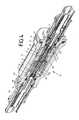
- FIG. 1shows an exploded drawing of a fiber-optic connection arrangement (prior art)
- FIG. 2shows an exploded drawing of a fiber-optic connection arrangement according to the invention
- FIG. 3shows a perspective view of a fiber-optic connection arrangement
- FIG. 4shows a perspective view of a section through the fiber-optic connection arrangement as shown in FIG. 3 .
- FIG. 5shows a cross section through the fiber-optic connection arrangement as illustrated in FIG. 3 .
- FIG. 1shows an exploded drawing of a fiber-optic connection arrangement 1 according to the prior art.
- the fiber-optic connection arrangement 1comprises a fiber-optic adapter 2 .
- the fiber-optic adapter 2has an outer section 3 and an inner section 4 , which are separated by a flange 5 , which is circumferential around a housing 25 of the fiber-optic adapter 2 .
- the fiber-optic adapter 2has a first connecting device 38 (see FIG. 4 ), which is not illustrated in FIG. 1 , within the housing 25 of the fiber-optic adapter 2 , and a second connecting device 6 .
- An attachment nut 7is also illustrated, and is screwed onto an external thread 8 (see FIG. 2 ) on the fiber-optic adapter 2 .
- the external thread 8may in this case be referred to as first adapter-side attachment means.
- the fiber-optic adapter 2has a second attachment means, in the form of an internal thread 9 .
- a first glass fiber cable 10is also illustrated, which is terminated by a first connecting plug 11 .
- the first connecting plug 11may be a connecting plug with a resistance capability.
- the first connecting plug 11has a plug head 12 in which a ferrule 22 (see FIG. 4 ) for the first glass fiber cable 10 is arranged.
- the first connecting plug 11has an attachment nut 13 , which has or forms an external threaded section 14 .
- the first connecting plug 11can be inserted into the fiber-optic adapter 2 through an opening which forms the internal thread 9 , with the plug head 12 being inserted into the first connecting device 38 , which is not illustrated.
- the plug head 12has guide elements 15 which, for example, correspond to guide elements, for example guide grooves, in the first connecting device 38 .
- the plug-side external thread 14can be screwed into the adapter-side internal thread 9 by rotation of the attachment nut 13 .
- a sealing washer 45is also illustrated, and is explained in more detail in FIG. 5 .
- a second glass fiber cable 16is likewise illustrated, which is terminated by a second connecting plug 17 .
- the second connecting plug 17is of a different type to the first connecting plug 11 .
- the second connecting plug 17likewise has a plug head 18 , which comprises a ferrule 19 for the second glass fiber cable 16 .
- the plug head 18can be inserted into the second connecting device 6 .
- the second connecting plug 17has guide elements which are in the form of guide webs 20 and correspond to guide slots or guide grooves 23 (see FIG. 2 ) in the second connecting device 6 .
- FIG. 2shows an exploded drawing of a fiber-optic connection arrangement 21 according to the invention.
- the fiber-optic connection arrangement 21comprises the fiber-optic adapter 2 illustrated in FIG. 1 .
- the first connecting plug 11is also illustrated, and is likewise illustrated in FIG. 1 .
- a ferrule 22is illustrated in the first connecting plug 11 , and a guide groove 23 in the second connecting device 6 .
- the external thread 8which is concealed in FIG. 1 , is also illustrated on the fiber-optic adapter 2 . As can be seen in this case, the external thread 8 is arranged on an outer casing surface 24 of the housing 25 of the fiber-optic adapter 2 . In this case, the external thread 8 is arranged on the inner section side, and is bounded by a flange 5 .
- the adapter sleeve 26has a first end section 27 with a first opening 28 and a second end section 29 with a second opening 30 .
- An internal volume 47 (see FIG. 5 ), which is not illustrated, in the adapter sleeve 26is accessible through the first opening 28 and the second opening 30 .
- the adapter sleeve 26is hollow for this purpose.
- the figurealso shows that a part of the first end section 27 is in the form of a flange 31 , with the flange 31 projecting in an annular shape from a main body 32 of the adapter sleeve 26 .
- This illustrates that the flange 31has flats 33 on an outer circumference, which flats 33 are used for better manual operation, in particular for better operation for screwing up or unscrewing the adapter sleeve 26 .
- the second end section 29has an internal thread 34 , with the internal thread 34 surrounding the second opening 30 .
- a diameter of the second opening 30is less than a diameter of the first opening 28 .
- the external dimensions, in particular an external diameter, of the adapter sleeve 26tapers from the first end section 27 toward the second end section 29 .
- An annular groove 35which is arranged on an external circumference of the second end section 29 , is also illustrated, for holding a closure cap holder (not illustrated).
- a further first connecting plug 11 ais also illustrated, of the same type as the first connecting plug 11 .
- the further first connecting plug 11 aalso has an attachment nut 13 and an external thread 14 connected to the attachment nut 13 .
- a nominal diameter of the sleeve-side internal thread 34corresponds to a nominal diameter of the plug-side external thread 14 .
- a plug head 12 of the further first connecting plug 11 acan thus be inserted into the internal volume 47 of the adapter sleeve 26 through the second opening 30 .
- the first further plug connector 11 acan thus be screwed by means of the external thread 14 to the internal thread 34 , by rotation of the attachment nut 13 , thus mechanically fixing the first further connecting plug 11 a to the adapter sleeve 26 .
- a first internal thread 35 on the adapter sleeve 26is not illustrated in FIG. 2 .
- a nominal diameter of the first internal thread 35corresponds to a nominal diameter of the external thread 8 .
- the adapter sleeve 26can thus be screwed onto the fiber-optic adapter 2 by means of the interacting threads 8 , 35 , with the second connecting device 6 being arranged in the internal volume 47 of the adapter sleeve 26 .
- a length L of the adapter sleeve 26 along a central longitudinal axis 37 of the adapter sleeve 26is in this case matched to a length, which is not illustrated, of the fiber-optic adapter 2 and of the first further connecting plug 11 a such that, when the adapter sleeve 26 is screwed onto the fiber-optic adapter 2 , the plug head 12 of the first further connecting plug 11 a can be inserted into the second connecting device 6 .
- the plug head 12can be mechanically fixed and aligned only incompletely by means of the second connecting device 6 .
- the mechanical fixing of the first further connecting plug 11 ais in this case assisted by screwing the plug-side external thread 14 to the sleeve-side second external thread 34 , wherein the plug head 12 of the first further connecting plug 11 a assumes a predetermined position, and also preferably a predetermined orientation, within the second connecting device 6 when the adapter sleeve 26 is screwed on and the further first connecting plug 11 a is screwed in.
- the flange 5acts as a stop for the sleeve-side flange 31 , as a result of which the adapter sleeve 26 can be screwed onto the fiber-optic adapter 2 only to a certain extent.
- FIG. 3illustrates the fiber-optic connection arrangement 21 as shown in FIG. 2 in a screwed-together state, with the connection arrangement 21 being illustrated rotated through 180°.
- the first connecting plug 11has been inserted into a first connecting device 38 (see FIG. 4 ), which is not illustrated, of the fiber-optic adapter 2 , and has been screwed to the fiber-optic adapter 2 .
- a first further connecting plug 11 ais introduced into an internal volume 47 (see FIG. 4 ), which is not illustrated, in the adapter sleeve 26 , and is inserted into the second connecting device 6 , which is illustrated, for example, in FIG. 1 .
- the first further connecting plug 11 ais screwed to the adapter sleeve 26 . This allows a mechanical and optical connection for glass fiber cables which have been terminated with the first connecting plugs 11 , 11 a.
- FIG. 4shows a perspective illustration of a cross section through the fiber-optic connection arrangement 21 illustrated in FIG. 3 .
- FIG. 4illustrates a first connecting device 38 , in which, in the present case, the plug head 12 of the first connecting plug 11 has been inserted.
- the figurealso shows the second connecting device 6 , into which the plug head 12 of the first further connecting plug 11 a is introduced.
- latching hooks 39 on the second connecting device 6engage in latching depressions 40 in the plug head 12 of the first further connecting plug 11 a .
- guide elements 15 on the first further connecting plug 11 aare introduced into the guide groove 23 in the second connecting device 6 (see FIG. 2 ).
- the guide elements 15 of the first further connecting plug 11 a and the guide groove 23 in the second connecting deviceare therefore used for predetermined alignment of the first further connecting plug 11 a in the second connecting device 6 .
- an outer surface 41 of the plug head 12 of the first further connecting plug 11 ais at a distance from an inner surface 42 of the second connecting device 6 , after having been introduced into the latter.
- an outer surface 41 of the plug head 12 of the first connecting plug 11is flush with an inner surface 43 of the first connecting device 38 .
- the first further connecting plug 11 ais mounted only incompletely in the second connecting device 6 since it can still be pivoted when it is attached only by means of the latching hooks 39 .
- the latching hooks 39 and the guide groove 23 which is illustrated in FIG. 2are used only for a predetermined and desired alignment of the first further connecting plug 11 a in the second connecting device 6 , and only partially for its mechanical fixing in the second connecting device 6 .
- the mechanical fixingis produced by screwing the plug-side external thread 14 to the second sleeve-side internal thread 30 .
- Sealing washers 44 , 45are also illustrated, and will be explained in more detail in the following text.
- FIG. 5shows a cross section through the fiber-optic connection arrangement 21 illustrated in FIG. 3 .
- a first sealing washer 44 and second sealing washers 45are illustrated in this case.
- the sleeve-side flange 31forms an annular contact surface 46 , which is bounded by the first flange 31 on an external circumference of the first sealing surface 46 .
- the first opening 28has a cross section in the form of a staircase and is incorporated in the end section 27 which comprises the first internal thread 36 and the flange 31 .
- the sealing surface 46is arranged on a plane which runs at right angles to the central longitudinal axis 37 of the adapter sleeve 26 .
- the sealing surface 46has a predetermined internal diameter and a predetermined external diameter.
- the sealing washer 44is pressed between the sleeve-side sealing surface 46 and the adapter-side flange 5 , thus sealing an internal volume 47 of the adapter sleeve 26 in a fluid-tight manner, in the area of the connection between the adapter sleeve 26 and the fiber-optic adapter 2 .
- Sealing washers 45are arranged on the first connecting plugs 11 , 11 a .
- the sealing washer 45is pressed between a further sealing surface 48 on the adapter sleeve 26 and the plug head 12 of the first further connecting plug 11 a .
- An internal diameter of at least a part of the second end section 29 of the adapter sleeve 26should be chosen for this purpose such that it is less than an external diameter of the sealing washer 45 which is arranged on the first further connecting plug 11 a .
- the internal volume 47 in the adapter sleeve 26is sealed in a fluid-tight manner when a first further connecting plug 11 a is screwed in.
- a fluid-tight sealis provided by means of the sealing washer 45 , which is arranged on the first connecting plug 11 .
- the fiber-optic adapter 2has a sealing surface 49 in the area of the first connecting device 38 .
- the first end section 27is in this case arranged opposite the second end section 29 along a central longitudinal axis 37 of the adapter sleeve 26 .
- That part of the second end section 29 on which the sealing washer 45 rests when the first further connecting plug 11 a is in the screwed-in statemay be referred to as a further sealing surface 48 of the adapter sleeve 26 .
Landscapes
- Physics & Mathematics (AREA)
- General Physics & Mathematics (AREA)
- Optics & Photonics (AREA)
- Mechanical Coupling Of Light Guides (AREA)
Abstract
Description
- 1 Fiber-optic connection arrangement
- 2 Fiber-optic adapter
- 3 Outer section
- 4 Inner section
- 5 Flange
- 6 Second connecting device
- 7 Attachment nut
- 8 External thread
- 9 Internal thread
- 10 First glass fiber cable
- 11 First connecting plug
- 12 Plug head
- 13 Attachment nut
- 14 External thread
- 15 Guide element
- 16 Second glass fiber cable
- 17 Second connecting plug
- 18 Plug head
- 19 Ferrule
- 20 Guide web
- 21 Fiber-optic connection arrangement
- 22 Ferrule
- 23 Guide groove
- 24 Outer casing
- 25 Housing
- 26 Adapter sleeve
- 27 First end section
- 28 First opening
- 29 Second end section
- 30 Second opening
- 31 Flange
- 32 Main body
- 33 Flat
- 34 Internal thread
- 35 Annular groove
- 36 Internal thread
- 37 Central longitudinal axis
- 38 First connecting device
- 39 Latching hook
- 40 Latching depression
- 41 Outer surface of the first further connecting plug
- 42 Inner surface
- 43 Inner surface of the first connecting device
- 44 Sealing washer
- 45 Sealing washer
- 46 First sealing surface
- 47 Internal volume
- 48 Further sealing surface
- 49 Sealing surface
Claims (13)
Priority Applications (1)
| Application Number | Priority Date | Filing Date | Title |
|---|---|---|---|
| US15/093,895US9739951B2 (en) | 2011-02-17 | 2016-04-08 | Fiber-optic connection arrangement and adapter sleeve |
Applications Claiming Priority (7)
| Application Number | Priority Date | Filing Date | Title |
|---|---|---|---|
| DE102011011523.4 | 2011-02-17 | ||
| DE201110011523DE102011011523B4 (en) | 2011-02-17 | 2011-02-17 | Fiber optic connection arrangement and adapter sleeve |
| DE102011011523 | 2011-02-17 | ||
| PCT/IB2012/000255WO2012110876A1 (en) | 2011-02-17 | 2012-02-10 | Fibre-optic connecting arrangement and adapter sleeve |
| US201314000018A | 2013-08-16 | 2013-08-16 | |
| US14/524,352US9310570B2 (en) | 2011-02-17 | 2014-10-27 | Fiber-optic connection arrangement and adapter sleeve |
| US15/093,895US9739951B2 (en) | 2011-02-17 | 2016-04-08 | Fiber-optic connection arrangement and adapter sleeve |
Related Parent Applications (1)
| Application Number | Title | Priority Date | Filing Date |
|---|---|---|---|
| US14/524,352ContinuationUS9310570B2 (en) | 2011-02-17 | 2014-10-27 | Fiber-optic connection arrangement and adapter sleeve |
Publications (2)
| Publication Number | Publication Date |
|---|---|
| US20160291260A1 US20160291260A1 (en) | 2016-10-06 |
| US9739951B2true US9739951B2 (en) | 2017-08-22 |
Family
ID=45974447
Family Applications (3)
| Application Number | Title | Priority Date | Filing Date |
|---|---|---|---|
| US14/000,018Expired - Fee RelatedUS8882364B2 (en) | 2011-02-17 | 2012-02-10 | Fiber-optic connecting arrangement and adapter sleeve |
| US14/524,352Expired - Fee RelatedUS9310570B2 (en) | 2011-02-17 | 2014-10-27 | Fiber-optic connection arrangement and adapter sleeve |
| US15/093,895ActiveUS9739951B2 (en) | 2011-02-17 | 2016-04-08 | Fiber-optic connection arrangement and adapter sleeve |
Family Applications Before (2)
| Application Number | Title | Priority Date | Filing Date |
|---|---|---|---|
| US14/000,018Expired - Fee RelatedUS8882364B2 (en) | 2011-02-17 | 2012-02-10 | Fiber-optic connecting arrangement and adapter sleeve |
| US14/524,352Expired - Fee RelatedUS9310570B2 (en) | 2011-02-17 | 2014-10-27 | Fiber-optic connection arrangement and adapter sleeve |
Country Status (8)
| Country | Link |
|---|---|
| US (3) | US8882364B2 (en) |
| EP (1) | EP2676160B1 (en) |
| CN (1) | CN103733103B (en) |
| AU (1) | AU2012219182C1 (en) |
| DE (1) | DE102011011523B4 (en) |
| RU (1) | RU2584718C2 (en) |
| UA (1) | UA110958C2 (en) |
| WO (1) | WO2012110876A1 (en) |
Cited By (27)
| Publication number | Priority date | Publication date | Assignee | Title |
|---|---|---|---|---|
| US10948664B2 (en) | 2018-05-08 | 2021-03-16 | Senko Advanced Components, Inc. | Ingress protected optical fiber connector having a reduced diameter with a removable retaining nut |
| US10976502B2 (en) | 2018-10-11 | 2021-04-13 | Seniko Advanced Components, Inc. | Outdoor rated assembly configured to blind mate opposing fiber optic connectors therein with a safety spring assembly |
| US11092756B2 (en) | 2018-10-10 | 2021-08-17 | Senko Advanced Components, Inc. | Ingress protected connector with an unitary orientation feature |
| US11215768B2 (en) | 2017-06-28 | 2022-01-04 | Corning Research & Development Corporation | Fiber optic connectors and connectorization employing adhesive admitting adapters |
| US11294133B2 (en) | 2019-07-31 | 2022-04-05 | Corning Research & Development Corporation | Fiber optic networks using multiports and cable assemblies with cable-to-connector orientation |
| US11300746B2 (en) | 2017-06-28 | 2022-04-12 | Corning Research & Development Corporation | Fiber optic port module inserts, assemblies and methods of making the same |
| US11307359B2 (en) | 2019-02-07 | 2022-04-19 | Senko Advanced Components, Inc. | Ingress protected, outdoor rated connector with integrated optical connector plug frame |
| US11422318B2 (en) | 2019-08-08 | 2022-08-23 | Senko Advanced Components, Inc. | Push pull mechanism for an outdoor rated connector assembly |
| US11487073B2 (en) | 2019-09-30 | 2022-11-01 | Corning Research & Development Corporation | Cable input devices having an integrated locking feature and assemblies using the cable input devices |
| US11536921B2 (en) | 2020-02-11 | 2022-12-27 | Corning Research & Development Corporation | Fiber optic terminals having one or more loopback assemblies |
| US11579374B2 (en) | 2018-04-02 | 2023-02-14 | Senko Advanced Components, Inc. | Hybrid ingress protected connector and adapter assembly |
| US11604320B2 (en) | 2020-09-30 | 2023-03-14 | Corning Research & Development Corporation | Connector assemblies for telecommunication enclosures |
| US11650388B2 (en) | 2019-11-14 | 2023-05-16 | Corning Research & Development Corporation | Fiber optic networks having a self-supporting optical terminal and methods of installing the optical terminal |
| US11668890B2 (en) | 2017-06-28 | 2023-06-06 | Corning Research & Development Corporation | Multiports and other devices having optical connection ports with securing features and methods of making the same |
| US11686913B2 (en) | 2020-11-30 | 2023-06-27 | Corning Research & Development Corporation | Fiber optic cable assemblies and connector assemblies having a crimp ring and crimp body and methods of fabricating the same |
| US11703646B2 (en) | 2017-06-28 | 2023-07-18 | Corning Research & Development Corporation | Multiports and optical connectors with rotationally discrete locking and keying features |
| US11880076B2 (en) | 2020-11-30 | 2024-01-23 | Corning Research & Development Corporation | Fiber optic adapter assemblies including a conversion housing and a release housing |
| US11886010B2 (en) | 2019-10-07 | 2024-01-30 | Corning Research & Development Corporation | Fiber optic terminals and fiber optic networks having variable ratio couplers |
| US11906795B2 (en) | 2019-06-19 | 2024-02-20 | Senko Advanced Components, Inc. | Fiber optic connector assembly with crimp tube subassembly and method of use |
| US11927810B2 (en) | 2020-11-30 | 2024-03-12 | Corning Research & Development Corporation | Fiber optic adapter assemblies including a conversion housing and a release member |
| US11947167B2 (en) | 2021-05-26 | 2024-04-02 | Corning Research & Development Corporation | Fiber optic terminals and tools and methods for adjusting a split ratio of a fiber optic terminal |
| US11994722B2 (en) | 2020-11-30 | 2024-05-28 | Corning Research & Development Corporation | Fiber optic adapter assemblies including an adapter housing and a locking housing |
| US12019279B2 (en) | 2019-05-31 | 2024-06-25 | Corning Research & Development Corporation | Multiports and other devices having optical connection ports with sliding actuators and methods of making the same |
| US12044894B2 (en) | 2018-12-28 | 2024-07-23 | Corning Research & Development Corporation | Multiport assemblies including mounting features or dust plugs |
| US12164153B2 (en) | 2019-01-09 | 2024-12-10 | Commscope Technologies Llc | Fiber optic adapter with integrally molded structures |
| US12271040B2 (en) | 2017-06-28 | 2025-04-08 | Corning Research & Development Corporation | Fiber optic extender ports, assemblies and methods of making the same |
| US12372727B2 (en) | 2020-10-30 | 2025-07-29 | Corning Research & Development Corporation | Female fiber optic connectors having a rocker latch arm and methods of making the same |
Families Citing this family (14)
| Publication number | Priority date | Publication date | Assignee | Title |
|---|---|---|---|---|
| DE102011011523B4 (en) | 2011-02-17 | 2013-05-29 | Tyco Electronics Services Gmbh | Fiber optic connection arrangement and adapter sleeve |
| BR112013025411A2 (en) | 2011-04-01 | 2016-12-20 | Tyco Electronics Corp | fiber optic adapters and connector devices with mounting capabilities and mounting systems and methods including the same |
| CN105683795A (en)* | 2013-08-24 | 2016-06-15 | 康普连通比利时有限责任公司 | Rugged Fiber Optic Connectors and Connection Systems |
| TWI489161B (en)* | 2013-11-08 | 2015-06-21 | Protai Photonic Co Ltd | Optical fiber adapter with shutter member |
| USD820210S1 (en)* | 2015-01-26 | 2018-06-12 | Tyco Electronics Svenska Ab | Electrical or optical connector |
| WO2017118749A2 (en)* | 2016-01-08 | 2017-07-13 | CommScope Connectivity Belgium BVBA | Ruggedized fiber optic adapter |
| CN207965228U (en)* | 2017-11-14 | 2018-10-12 | 烽火通信科技股份有限公司 | A kind of joint of connector, adapter and fast insert-pull |
| US11209599B2 (en)* | 2018-07-05 | 2021-12-28 | Senko Advanced Components, Inc. | Ingress protected, outdoor rated adapter and method of assembly to an outdoor connector |
| US11531166B2 (en) | 2019-04-29 | 2022-12-20 | Corning Research & Development Corporation | Optical connector assemblies, optical receptacle assemblies and optical connection systems having multiple optical fibers |
| US10852487B1 (en)* | 2019-08-09 | 2020-12-01 | Corning Research & Development Corporation | Hardened optical cable assemblies, optical plug connector assemblies, optical receptacle assemblies and optical connection systems having multiple optical fibers |
| WO2022020024A1 (en)* | 2020-07-24 | 2022-01-27 | Commscope Technologies Llc | Coaxial connector assemblies |
| WO2022271913A1 (en)* | 2021-06-23 | 2022-12-29 | Commscope Technologies Llc | Sealed fiber optic adapters and fiber optic connection systems |
| CN114594552B (en)* | 2022-01-18 | 2022-12-09 | 周孝龙 | Optical fiber ferrule assembling machine |
| WO2023207025A1 (en)* | 2022-04-29 | 2023-11-02 | 深圳市埃立康科技有限公司 | Single-core optical fiber adapter and optical fiber quick-connection assembly |
Citations (26)
| Publication number | Priority date | Publication date | Assignee | Title |
|---|---|---|---|---|
| JPS5216240A (en) | 1975-07-29 | 1977-02-07 | Nec Corp | Plug for photo fiber |
| GB2062283A (en) | 1979-11-05 | 1981-05-20 | Itt | Fibre optic connector |
| US4493529A (en) | 1982-07-30 | 1985-01-15 | Hughes Aircraft Company | Electromagnetic energy signal-carrying connector having secure strain-relief mechanism |
| US4793683A (en) | 1986-05-08 | 1988-12-27 | American Telephone And Telegraph Company, At&T Bell Laboratories | Optical fiber connector |
| US5115484A (en) | 1990-12-27 | 1992-05-19 | Square D Company | Multipurpose optical fiber connector |
| US5590229A (en) | 1994-04-22 | 1996-12-31 | Litton Systems, Inc. | Multichannel fiber optic connector |
| US6206579B1 (en) | 1998-10-29 | 2001-03-27 | Amphenol Corporation | Arrangement for integrating a rectangular fiber optic connector into a cylindrical connector |
| US6305849B1 (en) | 1999-02-09 | 2001-10-23 | Fiber Systems International | Multi-channel fiber optic connector |
| US6416334B1 (en) | 2000-03-24 | 2002-07-09 | Paul J. Plishner | Combination multi-conductor/optical fiber connector |
| US6579014B2 (en) | 2001-09-28 | 2003-06-17 | Corning Cable Systems Llc | Fiber optic receptacle |
| US6648520B2 (en) | 2001-09-28 | 2003-11-18 | Corning Cable Systems Llc | Fiber optic plug |
| US6652156B2 (en) | 2000-10-31 | 2003-11-25 | Sanwa Denki Kogyo Co., Ltd. | Optical connector plug |
| US20040038588A1 (en) | 2002-02-05 | 2004-02-26 | Christophe Bernardi | Plug device for a standard electrical or optical connection cord |
| US6739759B1 (en) | 2003-03-13 | 2004-05-25 | Itt Manufacturing Enterprises, Inc. | Protected optical interface |
| US20050041928A1 (en) | 2003-09-08 | 2005-02-24 | Zimmel Steven C. | Ruggedized fiber optic connection |
| US20050232553A1 (en) | 2004-04-14 | 2005-10-20 | Holmquist Marlon E | Fiber optic connector and method |
| US7090407B2 (en) | 2000-05-26 | 2006-08-15 | Corning Cable Systems Llc | Preconnectorized fiber optic drop cables and assemblies for efficient deployment |
| US7137742B2 (en) | 2004-08-24 | 2006-11-21 | Corning Cable Systems Llc | Fiber optic receptacle and plug assemblies with alignment and keying features |
| US7264402B2 (en) | 2005-03-10 | 2007-09-04 | Corning Cable Systems Llc | Multi-fiber optic receptacle and plug assembly |
| US7744288B2 (en) | 2007-12-11 | 2010-06-29 | Adc Telecommunications, Inc. | Hardened fiber optic connector compatible with hardened and non-hardened fiber optic adapters |
| US7785015B2 (en) | 2000-05-26 | 2010-08-31 | Corning Cable Systems Llc | Fiber optic drop cables and preconnectorized assemblies |
| US7785016B2 (en) | 2007-03-12 | 2010-08-31 | Corning Cable Systems Llc | Fiber optic adapter and connector assemblies |
| US20110200286A1 (en) | 2010-02-04 | 2011-08-18 | Adc Telecommunications, Inc. | Ruggedized Fiber Optic/Electrical Connection System |
| US8137002B2 (en) | 2007-05-06 | 2012-03-20 | Adc Telecommunications, Inc. | Mechanical interface converter for making non-ruggedized fiber optic connectors compatible with a ruggedized fiber optic adapter |
| US20130028569A1 (en)* | 2010-01-29 | 2013-01-31 | Tyco Electronics Raychem Bvba | Cable sealing device, cable trermination and attaching device |
| US8882364B2 (en) | 2011-02-17 | 2014-11-11 | Tyco Electronics Services Gmbh | Fiber-optic connecting arrangement and adapter sleeve |
Family Cites Families (4)
| Publication number | Priority date | Publication date | Assignee | Title |
|---|---|---|---|---|
| DE10141449A1 (en)* | 2001-08-23 | 2003-03-13 | Krone Gmbh | Universal Adapter |
| JP3483872B2 (en)* | 2002-05-22 | 2004-01-06 | 米沢電線株式会社 | Optical connector |
| US7614797B2 (en)* | 2007-01-24 | 2009-11-10 | Adc Telecommunications, Inc. | Fiber optic connector mechanical interface converter |
| CN201489139U (en)* | 2009-07-27 | 2010-05-26 | 赖石央 | Optical fiber connector |
- 2011
- 2011-02-17DEDE201110011523patent/DE102011011523B4/ennot_activeExpired - Fee Related
- 2012
- 2012-02-10AUAU2012219182Apatent/AU2012219182C1/ennot_activeCeased
- 2012-02-10CNCN201280018744.5Apatent/CN103733103B/ennot_activeExpired - Fee Related
- 2012-02-10EPEP12714832.8Apatent/EP2676160B1/enactiveActive
- 2012-02-10RURU2013142285/28Apatent/RU2584718C2/ennot_activeIP Right Cessation
- 2012-02-10USUS14/000,018patent/US8882364B2/ennot_activeExpired - Fee Related
- 2012-02-10WOPCT/IB2012/000255patent/WO2012110876A1/enactiveApplication Filing
- 2012-10-02UAUAA201310131Apatent/UA110958C2/enunknown
- 2014
- 2014-10-27USUS14/524,352patent/US9310570B2/ennot_activeExpired - Fee Related
- 2016
- 2016-04-08USUS15/093,895patent/US9739951B2/enactiveActive
Patent Citations (33)
| Publication number | Priority date | Publication date | Assignee | Title |
|---|---|---|---|---|
| JPS5216240A (en) | 1975-07-29 | 1977-02-07 | Nec Corp | Plug for photo fiber |
| GB2062283A (en) | 1979-11-05 | 1981-05-20 | Itt | Fibre optic connector |
| US4493529A (en) | 1982-07-30 | 1985-01-15 | Hughes Aircraft Company | Electromagnetic energy signal-carrying connector having secure strain-relief mechanism |
| US4793683A (en) | 1986-05-08 | 1988-12-27 | American Telephone And Telegraph Company, At&T Bell Laboratories | Optical fiber connector |
| US5115484A (en) | 1990-12-27 | 1992-05-19 | Square D Company | Multipurpose optical fiber connector |
| US5590229A (en) | 1994-04-22 | 1996-12-31 | Litton Systems, Inc. | Multichannel fiber optic connector |
| US6206579B1 (en) | 1998-10-29 | 2001-03-27 | Amphenol Corporation | Arrangement for integrating a rectangular fiber optic connector into a cylindrical connector |
| US6305849B1 (en) | 1999-02-09 | 2001-10-23 | Fiber Systems International | Multi-channel fiber optic connector |
| US6416334B1 (en) | 2000-03-24 | 2002-07-09 | Paul J. Plishner | Combination multi-conductor/optical fiber connector |
| US7918609B2 (en) | 2000-05-26 | 2011-04-05 | Corning Cable Systems Llc | Fiber optic drop cables and preconnectorized assemblies |
| US7881576B2 (en) | 2000-05-26 | 2011-02-01 | Corning Cable Systems Llc | Fiber optic drop cables and preconnectorized assemblies |
| US7785015B2 (en) | 2000-05-26 | 2010-08-31 | Corning Cable Systems Llc | Fiber optic drop cables and preconnectorized assemblies |
| US7090407B2 (en) | 2000-05-26 | 2006-08-15 | Corning Cable Systems Llc | Preconnectorized fiber optic drop cables and assemblies for efficient deployment |
| US6652156B2 (en) | 2000-10-31 | 2003-11-25 | Sanwa Denki Kogyo Co., Ltd. | Optical connector plug |
| US6648520B2 (en) | 2001-09-28 | 2003-11-18 | Corning Cable Systems Llc | Fiber optic plug |
| US6579014B2 (en) | 2001-09-28 | 2003-06-17 | Corning Cable Systems Llc | Fiber optic receptacle |
| US20040038588A1 (en) | 2002-02-05 | 2004-02-26 | Christophe Bernardi | Plug device for a standard electrical or optical connection cord |
| US6739759B1 (en) | 2003-03-13 | 2004-05-25 | Itt Manufacturing Enterprises, Inc. | Protected optical interface |
| US6962445B2 (en) | 2003-09-08 | 2005-11-08 | Adc Telecommunications, Inc. | Ruggedized fiber optic connection |
| US20050041928A1 (en) | 2003-09-08 | 2005-02-24 | Zimmel Steven C. | Ruggedized fiber optic connection |
| US20050232553A1 (en) | 2004-04-14 | 2005-10-20 | Holmquist Marlon E | Fiber optic connector and method |
| US7137742B2 (en) | 2004-08-24 | 2006-11-21 | Corning Cable Systems Llc | Fiber optic receptacle and plug assemblies with alignment and keying features |
| US7264402B2 (en) | 2005-03-10 | 2007-09-04 | Corning Cable Systems Llc | Multi-fiber optic receptacle and plug assembly |
| US7785016B2 (en) | 2007-03-12 | 2010-08-31 | Corning Cable Systems Llc | Fiber optic adapter and connector assemblies |
| US8137002B2 (en) | 2007-05-06 | 2012-03-20 | Adc Telecommunications, Inc. | Mechanical interface converter for making non-ruggedized fiber optic connectors compatible with a ruggedized fiber optic adapter |
| US7744288B2 (en) | 2007-12-11 | 2010-06-29 | Adc Telecommunications, Inc. | Hardened fiber optic connector compatible with hardened and non-hardened fiber optic adapters |
| US7959361B2 (en) | 2007-12-11 | 2011-06-14 | Adc Telecommunications, Inc. | Hardened fiber optic connection system |
| US20130028569A1 (en)* | 2010-01-29 | 2013-01-31 | Tyco Electronics Raychem Bvba | Cable sealing device, cable trermination and attaching device |
| US20110200286A1 (en) | 2010-02-04 | 2011-08-18 | Adc Telecommunications, Inc. | Ruggedized Fiber Optic/Electrical Connection System |
| US8480312B2 (en) | 2010-02-04 | 2013-07-09 | Adc Telecommunications, Inc. | Ruggedized fiber optic/electrical connection system |
| US8894300B2 (en) | 2010-02-04 | 2014-11-25 | Adc Telecommunications, Inc. | Ruggedized fiber optic/electrical connection system |
| US8882364B2 (en) | 2011-02-17 | 2014-11-11 | Tyco Electronics Services Gmbh | Fiber-optic connecting arrangement and adapter sleeve |
| US9310570B2 (en) | 2011-02-17 | 2016-04-12 | Commscope Technologies Llc | Fiber-optic connection arrangement and adapter sleeve |
Non-Patent Citations (1)
| Title |
|---|
| International Search Report for International Application No. PCT/IB2012/000255 mailed Jul. 31, 2012. (3 pages). |
Cited By (65)
| Publication number | Priority date | Publication date | Assignee | Title |
|---|---|---|---|---|
| US11668890B2 (en) | 2017-06-28 | 2023-06-06 | Corning Research & Development Corporation | Multiports and other devices having optical connection ports with securing features and methods of making the same |
| US11493700B2 (en) | 2017-06-28 | 2022-11-08 | Corning Research & Development Corporation | Compact fiber optic connectors, cable assemblies and methods of making the same |
| US11966089B2 (en) | 2017-06-28 | 2024-04-23 | Corning Optical Communications, Llc | Multiports having connection ports formed in the shell and associated securing features |
| US11215768B2 (en) | 2017-06-28 | 2022-01-04 | Corning Research & Development Corporation | Fiber optic connectors and connectorization employing adhesive admitting adapters |
| US11262509B2 (en) | 2017-06-28 | 2022-03-01 | Corning Research & Development Corporation | Compact fiber optic connectors having multiple connector footprints, along with cable assemblies and methods of making the same |
| US11287581B2 (en) | 2017-06-28 | 2022-03-29 | Corning Research & Development Corporation | Compact fiber optic connectors, cable assemblies and methods of making the same |
| US11287582B2 (en) | 2017-06-28 | 2022-03-29 | Corning Research & Development Corporation | Compact fiber optic connectors, cable assemblies and methods of making the same |
| US12429655B2 (en) | 2017-06-28 | 2025-09-30 | Corning Optical Communications LLC | Multiports having connection ports with associated securing features and methods of making the same |
| US11300746B2 (en) | 2017-06-28 | 2022-04-12 | Corning Research & Development Corporation | Fiber optic port module inserts, assemblies and methods of making the same |
| US11300735B2 (en) | 2017-06-28 | 2022-04-12 | Corning Research & Development Corporation | Compact fiber optic connectors having multiple connector footprints, along with cable assemblies and methods of making the same |
| US12379552B2 (en) | 2017-06-28 | 2025-08-05 | Corning Research & Development Corporation | Compact fiber optic connectors, cable assemblies and methods of making the same |
| US11307364B2 (en) | 2017-06-28 | 2022-04-19 | Corning Research & Development Corporation | Compact fiber optic connectors having multiple connector footprints, along with cable assemblies and methods of making the same |
| US11327247B2 (en) | 2017-06-28 | 2022-05-10 | Corning Optical Communications LLC | Multiports having connection ports formed in the shell and associated securing features |
| US11914198B2 (en) | 2017-06-28 | 2024-02-27 | Corning Research & Development Corporation | Compact fiber optic connectors having multiple connector footprints, along with cable assemblies and methods of making the same |
| US11409055B2 (en) | 2017-06-28 | 2022-08-09 | Corning Optical Communications LLC | Multiports having connection ports with associated securing features and methods of making the same |
| US11415759B2 (en) | 2017-06-28 | 2022-08-16 | Corning Optical Communications LLC | Multiports having a connection port insert and methods of making the same |
| US12379551B2 (en) | 2017-06-28 | 2025-08-05 | Corning Optical Communications LLC | Multiports having connection ports formed in the shell and associated securing features |
| US11460646B2 (en) | 2017-06-28 | 2022-10-04 | Corning Research & Development Corporation | Fiber optic connectors and multiport assemblies including retention features |
| US11487065B2 (en) | 2017-06-28 | 2022-11-01 | Corning Research & Development Corporation | Multiports and devices having a connector port with a rotating securing feature |
| US12353024B2 (en) | 2017-06-28 | 2025-07-08 | Corning Research & Development Corporation | Multiports and optical connectors with rotationally discrete locking and keying features |
| US11493699B2 (en) | 2017-06-28 | 2022-11-08 | Corning Research & Development Corporation | Multifiber fiber optic connectors, cable assemblies and methods of making the same |
| US11940656B2 (en) | 2017-06-28 | 2024-03-26 | Corning Research & Development Corporation | Compact fiber optic connectors, cable assemblies and methods of making the same |
| US11531168B2 (en) | 2017-06-28 | 2022-12-20 | Corning Research & Development Corporation | Fiber optic connectors having a keying structure and methods of making the same |
| US11536913B2 (en) | 2017-06-28 | 2022-12-27 | Corning Research & Development Corporation | Fiber optic connectors and connectorization employing adhesive admitting adapters |
| US12353025B2 (en) | 2017-06-28 | 2025-07-08 | Corning Optical Communications LLC | Multiports having a connection port insert and methods of making the same |
| US11543600B2 (en) | 2017-06-28 | 2023-01-03 | Corning Research & Development Corporation | Compact fiber optic connectors having multiple connector footprints, along with cable assemblies and methods of making the same |
| US11579377B2 (en) | 2017-06-28 | 2023-02-14 | Corning Research & Development Corporation | Compact fiber optic connectors, cable assemblies and methods of making the same with alignment elements |
| US11914197B2 (en) | 2017-06-28 | 2024-02-27 | Corning Research & Development Corporation | Compact fiber optic connectors having multiple connector footprints, along with cable assemblies and methods of making the same |
| US12298568B2 (en) | 2017-06-28 | 2025-05-13 | Corning Research & Development Corporation | Fiber optic connectors and multiport assemblies including retention features |
| US11624877B2 (en) | 2017-06-28 | 2023-04-11 | Corning Research & Development Corporation | Multiports having connection ports with securing features that actuate flexures and methods of making the same |
| US12276846B2 (en) | 2017-06-28 | 2025-04-15 | Corning Research & Development Corporation | Compact fiber optic connectors, cable assemblies and methods of making the same |
| US11656414B2 (en) | 2017-06-28 | 2023-05-23 | Corning Research & Development Corporation | Multiports and other devices having connection ports with securing features and methods of making the same |
| US11703646B2 (en) | 2017-06-28 | 2023-07-18 | Corning Research & Development Corporation | Multiports and optical connectors with rotationally discrete locking and keying features |
| US12271040B2 (en) | 2017-06-28 | 2025-04-08 | Corning Research & Development Corporation | Fiber optic extender ports, assemblies and methods of making the same |
| US11906792B2 (en) | 2017-06-28 | 2024-02-20 | Corning Research & Development Corporation | Compact fiber optic connectors having multiple connector footprints, along with cable assemblies and methods of making the same |
| US11789214B2 (en) | 2017-06-28 | 2023-10-17 | Corning Research & Development Corporation | Multiports and other devices having keyed connection ports and securing features and methods of making the same |
| US12174432B2 (en) | 2017-06-28 | 2024-12-24 | Corning Research & Development Corporation | Fiber optic connectors and connectorization employing adhesive admitting adapters |
| US12092878B2 (en) | 2017-06-28 | 2024-09-17 | Corning Research & Development Corporation | Fiber optic connectors having a keying structure and methods of making the same |
| US11886017B2 (en) | 2017-06-28 | 2024-01-30 | Corning Research & Development Corporation | Multiports and other devices having connection ports with securing features and methods of making the same |
| US12013578B2 (en) | 2017-06-28 | 2024-06-18 | Corning Research & Development Corporation | Multifiber fiber optic connectors, cable assemblies and methods of making the same |
| US11579374B2 (en) | 2018-04-02 | 2023-02-14 | Senko Advanced Components, Inc. | Hybrid ingress protected connector and adapter assembly |
| US10948664B2 (en) | 2018-05-08 | 2021-03-16 | Senko Advanced Components, Inc. | Ingress protected optical fiber connector having a reduced diameter with a removable retaining nut |
| US11385416B2 (en) | 2018-05-08 | 2022-07-12 | Senko Advanced Components, Inc. | Ingress protected optic fiber connector having a reduced diameter with a removable retaining nut |
| US11092756B2 (en) | 2018-10-10 | 2021-08-17 | Senko Advanced Components, Inc. | Ingress protected connector with an unitary orientation feature |
| US10976502B2 (en) | 2018-10-11 | 2021-04-13 | Seniko Advanced Components, Inc. | Outdoor rated assembly configured to blind mate opposing fiber optic connectors therein with a safety spring assembly |
| US12044894B2 (en) | 2018-12-28 | 2024-07-23 | Corning Research & Development Corporation | Multiport assemblies including mounting features or dust plugs |
| US12164153B2 (en) | 2019-01-09 | 2024-12-10 | Commscope Technologies Llc | Fiber optic adapter with integrally molded structures |
| US11307359B2 (en) | 2019-02-07 | 2022-04-19 | Senko Advanced Components, Inc. | Ingress protected, outdoor rated connector with integrated optical connector plug frame |
| US12019279B2 (en) | 2019-05-31 | 2024-06-25 | Corning Research & Development Corporation | Multiports and other devices having optical connection ports with sliding actuators and methods of making the same |
| US11906795B2 (en) | 2019-06-19 | 2024-02-20 | Senko Advanced Components, Inc. | Fiber optic connector assembly with crimp tube subassembly and method of use |
| US11294133B2 (en) | 2019-07-31 | 2022-04-05 | Corning Research & Development Corporation | Fiber optic networks using multiports and cable assemblies with cable-to-connector orientation |
| US11422318B2 (en) | 2019-08-08 | 2022-08-23 | Senko Advanced Components, Inc. | Push pull mechanism for an outdoor rated connector assembly |
| US11487073B2 (en) | 2019-09-30 | 2022-11-01 | Corning Research & Development Corporation | Cable input devices having an integrated locking feature and assemblies using the cable input devices |
| US11886010B2 (en) | 2019-10-07 | 2024-01-30 | Corning Research & Development Corporation | Fiber optic terminals and fiber optic networks having variable ratio couplers |
| US11650388B2 (en) | 2019-11-14 | 2023-05-16 | Corning Research & Development Corporation | Fiber optic networks having a self-supporting optical terminal and methods of installing the optical terminal |
| US11536921B2 (en) | 2020-02-11 | 2022-12-27 | Corning Research & Development Corporation | Fiber optic terminals having one or more loopback assemblies |
| US11604320B2 (en) | 2020-09-30 | 2023-03-14 | Corning Research & Development Corporation | Connector assemblies for telecommunication enclosures |
| US12019285B2 (en) | 2020-09-30 | 2024-06-25 | Corning Research & Development Corporation | Connector assemblies for telecommunication enclosures |
| US12372727B2 (en) | 2020-10-30 | 2025-07-29 | Corning Research & Development Corporation | Female fiber optic connectors having a rocker latch arm and methods of making the same |
| US11880076B2 (en) | 2020-11-30 | 2024-01-23 | Corning Research & Development Corporation | Fiber optic adapter assemblies including a conversion housing and a release housing |
| US11686913B2 (en) | 2020-11-30 | 2023-06-27 | Corning Research & Development Corporation | Fiber optic cable assemblies and connector assemblies having a crimp ring and crimp body and methods of fabricating the same |
| US12345927B2 (en) | 2020-11-30 | 2025-07-01 | Corning Research & Development Corporation | Fiber optic adapter assemblies including a conversion housing and a release housing |
| US11994722B2 (en) | 2020-11-30 | 2024-05-28 | Corning Research & Development Corporation | Fiber optic adapter assemblies including an adapter housing and a locking housing |
| US11927810B2 (en) | 2020-11-30 | 2024-03-12 | Corning Research & Development Corporation | Fiber optic adapter assemblies including a conversion housing and a release member |
| US11947167B2 (en) | 2021-05-26 | 2024-04-02 | Corning Research & Development Corporation | Fiber optic terminals and tools and methods for adjusting a split ratio of a fiber optic terminal |
Also Published As
| Publication number | Publication date |
|---|---|
| RU2013142285A (en) | 2015-03-27 |
| EP2676160A1 (en) | 2013-12-25 |
| US9310570B2 (en) | 2016-04-12 |
| CN103733103A (en) | 2014-04-16 |
| EP2676160B1 (en) | 2019-05-15 |
| UA110958C2 (en) | 2016-03-10 |
| RU2584718C2 (en) | 2016-05-20 |
| AU2012219182B2 (en) | 2015-12-17 |
| WO2012110876A1 (en) | 2012-08-23 |
| US20130322828A1 (en) | 2013-12-05 |
| AU2012219182C1 (en) | 2016-05-12 |
| AU2012219182A1 (en) | 2013-08-22 |
| DE102011011523A1 (en) | 2012-08-23 |
| US20160291260A1 (en) | 2016-10-06 |
| CN103733103B (en) | 2016-05-18 |
| US20150043870A1 (en) | 2015-02-12 |
| US8882364B2 (en) | 2014-11-11 |
| DE102011011523B4 (en) | 2013-05-29 |
Similar Documents
| Publication | Publication Date | Title |
|---|---|---|
| US9739951B2 (en) | Fiber-optic connection arrangement and adapter sleeve | |
| JP3240929U (en) | Fiber optic subassemblies and fiber optic connectors | |
| US10613278B2 (en) | Cable sealing device, cable termination and attaching device | |
| CN109642992B (en) | Fiber Optic Connectors, Fiber Optic Adapters and Fiber Optic Connectors | |
| US8853537B2 (en) | Cable sealing and retaining device | |
| JP5273916B2 (en) | Connection device | |
| US4339172A (en) | Connector having a single segmented deformable grip member for optical cables | |
| CN110542952B (en) | Optical fiber connector and optical fiber connector | |
| US20200284993A1 (en) | Optical fiber connector | |
| CN101952757B (en) | Cable inserts with upstream mounting fixtures | |
| CN110297294B (en) | Prefabricated optical cable assembly and prefabricated optical cable connector | |
| CN105917259A (en) | Connecting member and optical fibre connector | |
| US11327246B2 (en) | Optical fiber connector, prefabricated optical fiber, adapter, fiber termination box, and optical fiber connection assembly | |
| US7563033B2 (en) | Housing for fiber-optic plug-in connector, and a method for laying fiber-optic cables | |
| CN102385114B (en) | For holding the adapter of hybrid connector part and joints of optical fibre part | |
| AU2015261569B2 (en) | Fibre-optic connecting arrangement and adapter sleeve | |
| US12019281B2 (en) | Sealed optical cable assemblies and methods of fabricating the same | |
| CN106324766B (en) | Optical fiber pre-connecting piece and terminal box with same | |
| CN115799896A (en) | Immersed sealing connector | |
| CN111338031A (en) | a fiber optic connector |
Legal Events
| Date | Code | Title | Description |
|---|---|---|---|
| STCF | Information on status: patent grant | Free format text:PATENTED CASE | |
| AS | Assignment | Owner name:WILMINGTON TRUST, NATIONAL ASSOCIATION, AS COLLATE Free format text:PATENT SECURITY AGREEMENT;ASSIGNOR:COMMSCOPE TECHNOLOGIES LLC;REEL/FRAME:049892/0051 Effective date:20190404 Owner name:JPMORGAN CHASE BANK, N.A., NEW YORK Free format text:ABL SECURITY AGREEMENT;ASSIGNORS:COMMSCOPE, INC. OF NORTH CAROLINA;COMMSCOPE TECHNOLOGIES LLC;ARRIS ENTERPRISES LLC;AND OTHERS;REEL/FRAME:049892/0396 Effective date:20190404 Owner name:JPMORGAN CHASE BANK, N.A., NEW YORK Free format text:TERM LOAN SECURITY AGREEMENT;ASSIGNORS:COMMSCOPE, INC. OF NORTH CAROLINA;COMMSCOPE TECHNOLOGIES LLC;ARRIS ENTERPRISES LLC;AND OTHERS;REEL/FRAME:049905/0504 Effective date:20190404 Owner name:WILMINGTON TRUST, NATIONAL ASSOCIATION, AS COLLATERAL AGENT, CONNECTICUT Free format text:PATENT SECURITY AGREEMENT;ASSIGNOR:COMMSCOPE TECHNOLOGIES LLC;REEL/FRAME:049892/0051 Effective date:20190404 | |
| MAFP | Maintenance fee payment | Free format text:PAYMENT OF MAINTENANCE FEE, 4TH YEAR, LARGE ENTITY (ORIGINAL EVENT CODE: M1551); ENTITY STATUS OF PATENT OWNER: LARGE ENTITY Year of fee payment:4 | |
| AS | Assignment | Owner name:WILMINGTON TRUST, DELAWARE Free format text:SECURITY INTEREST;ASSIGNORS:ARRIS SOLUTIONS, INC.;ARRIS ENTERPRISES LLC;COMMSCOPE TECHNOLOGIES LLC;AND OTHERS;REEL/FRAME:060752/0001 Effective date:20211115 | |
| AS | Assignment | Owner name:APOLLO ADMINISTRATIVE AGENCY LLC, NEW YORK Free format text:SECURITY INTEREST;ASSIGNORS:ARRIS ENTERPRISES LLC;COMMSCOPE TECHNOLOGIES LLC;COMMSCOPE INC., OF NORTH CAROLINA;AND OTHERS;REEL/FRAME:069889/0114 Effective date:20241217 | |
| AS | Assignment | Owner name:RUCKUS WIRELESS, LLC (F/K/A RUCKUS WIRELESS, INC.), NORTH CAROLINA Free format text:RELEASE OF SECURITY INTEREST AT REEL/FRAME 049905/0504;ASSIGNOR:JPMORGAN CHASE BANK, N.A., AS COLLATERAL AGENT;REEL/FRAME:071477/0255 Effective date:20241217 Owner name:COMMSCOPE TECHNOLOGIES LLC, NORTH CAROLINA Free format text:RELEASE OF SECURITY INTEREST AT REEL/FRAME 049905/0504;ASSIGNOR:JPMORGAN CHASE BANK, N.A., AS COLLATERAL AGENT;REEL/FRAME:071477/0255 Effective date:20241217 Owner name:COMMSCOPE, INC. OF NORTH CAROLINA, NORTH CAROLINA Free format text:RELEASE OF SECURITY INTEREST AT REEL/FRAME 049905/0504;ASSIGNOR:JPMORGAN CHASE BANK, N.A., AS COLLATERAL AGENT;REEL/FRAME:071477/0255 Effective date:20241217 Owner name:ARRIS SOLUTIONS, INC., NORTH CAROLINA Free format text:RELEASE OF SECURITY INTEREST AT REEL/FRAME 049905/0504;ASSIGNOR:JPMORGAN CHASE BANK, N.A., AS COLLATERAL AGENT;REEL/FRAME:071477/0255 Effective date:20241217 Owner name:ARRIS TECHNOLOGY, INC., NORTH CAROLINA Free format text:RELEASE OF SECURITY INTEREST AT REEL/FRAME 049905/0504;ASSIGNOR:JPMORGAN CHASE BANK, N.A., AS COLLATERAL AGENT;REEL/FRAME:071477/0255 Effective date:20241217 Owner name:ARRIS ENTERPRISES LLC (F/K/A ARRIS ENTERPRISES, INC.), NORTH CAROLINA Free format text:RELEASE OF SECURITY INTEREST AT REEL/FRAME 049905/0504;ASSIGNOR:JPMORGAN CHASE BANK, N.A., AS COLLATERAL AGENT;REEL/FRAME:071477/0255 Effective date:20241217 | |
| MAFP | Maintenance fee payment | Free format text:PAYMENT OF MAINTENANCE FEE, 8TH YEAR, LARGE ENTITY (ORIGINAL EVENT CODE: M1552); ENTITY STATUS OF PATENT OWNER: LARGE ENTITY Year of fee payment:8 |