US9739891B2 - System and method of using measurements of opportunity with vector tracking filters for improved navigation - Google Patents
System and method of using measurements of opportunity with vector tracking filters for improved navigationDownload PDFInfo
- Publication number
- US9739891B2 US9739891B2US14/328,180US201414328180AUS9739891B2US 9739891 B2US9739891 B2US 9739891B2US 201414328180 AUS201414328180 AUS 201414328180AUS 9739891 B2US9739891 B2US 9739891B2
- Authority
- US
- United States
- Prior art keywords
- data
- mobile device
- pvt
- tracking
- satellite
- Prior art date
- Legal status (The legal status is an assumption and is not a legal conclusion. Google has not performed a legal analysis and makes no representation as to the accuracy of the status listed.)
- Active, expires
Links
- 238000005259measurementMethods0.000titleclaimsabstractdescription66
- 238000000034methodMethods0.000titleclaimsabstractdescription42
- 239000013598vectorSubstances0.000titleclaimsdescription56
- 230000005540biological transmissionEffects0.000claimsdescription7
- 230000001413cellular effectEffects0.000claimsdescription4
- 238000013442quality metricsMethods0.000claims7
- 238000012545processingMethods0.000description22
- 238000004422calculation algorithmMethods0.000description15
- 230000006870functionEffects0.000description15
- 238000004891communicationMethods0.000description13
- 239000011159matrix materialSubstances0.000description11
- 230000008569processEffects0.000description11
- 238000004590computer programMethods0.000description10
- 239000003795chemical substances by applicationSubstances0.000description9
- 230000006872improvementEffects0.000description8
- 230000008878couplingEffects0.000description7
- 238000010168coupling processMethods0.000description7
- 238000005859coupling reactionMethods0.000description7
- 238000009795derivationMethods0.000description7
- 230000008901benefitEffects0.000description6
- 238000005516engineering processMethods0.000description6
- 230000003287optical effectEffects0.000description6
- 230000008859changeEffects0.000description5
- 238000013507mappingMethods0.000description5
- 238000013459approachMethods0.000description4
- 238000010586diagramMethods0.000description4
- 230000004807localizationEffects0.000description4
- XUIMIQQOPSSXEZ-UHFFFAOYSA-NSiliconChemical compound[Si]XUIMIQQOPSSXEZ-UHFFFAOYSA-N0.000description3
- 238000004364calculation methodMethods0.000description3
- 230000003993interactionEffects0.000description3
- 239000010410layerSubstances0.000description3
- 238000011326mechanical measurementMethods0.000description3
- 229910052710siliconInorganic materials0.000description3
- 239000010703siliconSubstances0.000description3
- 238000004458analytical methodMethods0.000description2
- 238000011161developmentMethods0.000description2
- 230000000694effectsEffects0.000description2
- GVVPGTZRZFNKDS-JXMROGBWSA-Ngeranyl diphosphateChemical compoundCC(C)=CCC\C(C)=C\CO[P@](O)(=O)OP(O)(O)=OGVVPGTZRZFNKDS-JXMROGBWSA-N0.000description2
- 230000033001locomotionEffects0.000description2
- 238000013508migrationMethods0.000description2
- 230000005012migrationEffects0.000description2
- 238000012986modificationMethods0.000description2
- 230000004048modificationEffects0.000description2
- 238000005295random walkMethods0.000description2
- 238000011160researchMethods0.000description2
- 238000013515scriptMethods0.000description2
- 238000000926separation methodMethods0.000description2
- 238000004088simulationMethods0.000description2
- 239000000243solutionSubstances0.000description2
- 238000012935AveragingMethods0.000description1
- 238000010420art techniqueMethods0.000description1
- 230000002238attenuated effectEffects0.000description1
- 230000003416augmentationEffects0.000description1
- 230000006399behaviorEffects0.000description1
- 238000012937correctionMethods0.000description1
- 230000007812deficiencyEffects0.000description1
- 230000006735deficitEffects0.000description1
- 230000001419dependent effectEffects0.000description1
- 238000013461designMethods0.000description1
- 238000010790dilutionMethods0.000description1
- 239000012895dilutionSubstances0.000description1
- 230000003467diminishing effectEffects0.000description1
- 230000009429distressEffects0.000description1
- 238000001914filtrationMethods0.000description1
- 238000009472formulationMethods0.000description1
- 230000036039immunityEffects0.000description1
- 230000001771impaired effectEffects0.000description1
- 239000002346layers by functionSubstances0.000description1
- 238000012886linear functionMethods0.000description1
- 239000004973liquid crystal related substanceSubstances0.000description1
- 239000000203mixtureSubstances0.000description1
- 238000012544monitoring processMethods0.000description1
- 230000000737periodic effectEffects0.000description1
- 238000003672processing methodMethods0.000description1
- 238000012552reviewMethods0.000description1
- 239000004065semiconductorSubstances0.000description1
- 230000035945sensitivityEffects0.000description1
- 230000004622sleep timeEffects0.000description1
- 230000003595spectral effectEffects0.000description1
- 239000000758substrateSubstances0.000description1
- 238000012360testing methodMethods0.000description1
- 238000012546transferMethods0.000description1
Images


Classifications
- G—PHYSICS
- G01—MEASURING; TESTING
- G01S—RADIO DIRECTION-FINDING; RADIO NAVIGATION; DETERMINING DISTANCE OR VELOCITY BY USE OF RADIO WAVES; LOCATING OR PRESENCE-DETECTING BY USE OF THE REFLECTION OR RERADIATION OF RADIO WAVES; ANALOGOUS ARRANGEMENTS USING OTHER WAVES
- G01S19/00—Satellite radio beacon positioning systems; Determining position, velocity or attitude using signals transmitted by such systems
- G01S19/38—Determining a navigation solution using signals transmitted by a satellite radio beacon positioning system
- G01S19/39—Determining a navigation solution using signals transmitted by a satellite radio beacon positioning system the satellite radio beacon positioning system transmitting time-stamped messages, e.g. GPS [Global Positioning System], GLONASS [Global Orbiting Navigation Satellite System] or GALILEO
- G01S19/42—Determining position
- G01S19/45—Determining position by combining measurements of signals from the satellite radio beacon positioning system with a supplementary measurement
- G01S19/46—Determining position by combining measurements of signals from the satellite radio beacon positioning system with a supplementary measurement the supplementary measurement being of a radio-wave signal type
- G—PHYSICS
- G01—MEASURING; TESTING
- G01S—RADIO DIRECTION-FINDING; RADIO NAVIGATION; DETERMINING DISTANCE OR VELOCITY BY USE OF RADIO WAVES; LOCATING OR PRESENCE-DETECTING BY USE OF THE REFLECTION OR RERADIATION OF RADIO WAVES; ANALOGOUS ARRANGEMENTS USING OTHER WAVES
- G01S5/00—Position-fixing by co-ordinating two or more direction or position line determinations; Position-fixing by co-ordinating two or more distance determinations
- G01S5/02—Position-fixing by co-ordinating two or more direction or position line determinations; Position-fixing by co-ordinating two or more distance determinations using radio waves
- G01S5/0205—Details
- G01S5/0242—Determining the position of transmitters to be subsequently used in positioning
- G—PHYSICS
- G01—MEASURING; TESTING
- G01S—RADIO DIRECTION-FINDING; RADIO NAVIGATION; DETERMINING DISTANCE OR VELOCITY BY USE OF RADIO WAVES; LOCATING OR PRESENCE-DETECTING BY USE OF THE REFLECTION OR RERADIATION OF RADIO WAVES; ANALOGOUS ARRANGEMENTS USING OTHER WAVES
- G01S5/00—Position-fixing by co-ordinating two or more direction or position line determinations; Position-fixing by co-ordinating two or more distance determinations
- G01S5/02—Position-fixing by co-ordinating two or more direction or position line determinations; Position-fixing by co-ordinating two or more distance determinations using radio waves
- G01S5/0252—Radio frequency fingerprinting
- G01S5/02521—Radio frequency fingerprinting using a radio-map
- G—PHYSICS
- G01—MEASURING; TESTING
- G01S—RADIO DIRECTION-FINDING; RADIO NAVIGATION; DETERMINING DISTANCE OR VELOCITY BY USE OF RADIO WAVES; LOCATING OR PRESENCE-DETECTING BY USE OF THE REFLECTION OR RERADIATION OF RADIO WAVES; ANALOGOUS ARRANGEMENTS USING OTHER WAVES
- G01S5/00—Position-fixing by co-ordinating two or more direction or position line determinations; Position-fixing by co-ordinating two or more distance determinations
- G01S5/02—Position-fixing by co-ordinating two or more direction or position line determinations; Position-fixing by co-ordinating two or more distance determinations using radio waves
- G01S5/0284—Relative positioning
- G01S5/0289—Relative positioning of multiple transceivers, e.g. in ad hoc networks
Definitions
- SoOPradio frequency
- Examples of SoOPsinclude cellular downlink broadcasts, WiFi access points, television signals, terrestrial radio AM and FM signals, etc.
- the present disclosurerepresents a means to provide large gains in geolocation and navigation performance vs. diminishing incremental benefits from traditional GPS user equipment research topics.
- the goalis to be able to maintain the same level of accuracy as a GPS in GPS-unavailable environments, without adding significant system complexity, cost, or operational burdens. These gains can benefit the growing markets and applications in both the military and commercial sectors.
- FIG. 1illustrates a prior art traditional GNSS receiver architecture.
- FIG. 2illustrates one embodiment of the present disclosure showing vector tracking loops.
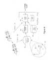
- FIG. 3illustrates a simplified pictorial representation of one example of Applicant's previous disclosure including small robotic vehicles which can navigate within the hallways of a building by signals of opportunity (SoOP).
- SoOPsignals of opportunity
- FIG. 4illustrates a simplified flow diagram showing use of the Applicant's previous disclosure of the SMARTS (simultaneous mapping and relative timing using SoOPs) algorithm used with the present disclosure.
- FIG. 5illustrates a simplified flow diagram of the function of the METEOR algorithm for use with one embodiment of the present disclosure.
- FIG. 6illustrates the a simplified flow diagram of the function of the Hyper-time algorithm for use with one embodiment of the present disclosure.
- FIG. 7illustrates the progression of global navigation satellite system receiver architectures from dedicated silicon based of the prior to software defined radio (SDR) architecture that is used with an embodiment of the present disclosure.
- SDRsoftware defined radio
- FIG. 1illustrates the progression of prior art techniques for locating a mobile device.
- Prior art ultra-tight couplingtypically used all available satellite measurements and mechanical measurements in a statistical filter framework (such as an extended Kalman filter (EKF)) to estimate the time and position of the host platform so that the carrier frequency and code phase of the navigation satellite can be accurately estimated for tracking of the navigation satellite in attenuated/multipath propagation scenarios.
- EKFextended Kalman filter
- SDRsoftware defined radio
- GNSSglobal navigation satellite system
- the physical layeris defined as the functions from the antenna to the A/D converter 100 , the measurement layer as the acquisition and tracking functions 110 , and the application layer as the location/time estimating Kalman Filter 120 .
- a VDFLLvector delay frequency lock loop
- a conventional VDFLLhas been well documented in the literature including in “Implementation of a Vector-based Tracking Loop Receiver in a Pseudolite Navigation System” by Hyoungmin So et al, published in Sensors in 2010.
- Vector tracking 140is a technology that replaced individual satellite vehicle (SV) tracking loops 142 , 144 to include a statistical filter, such as an EKF 130 , that drive each loop oscillator for a navigational satellite.
- SVsatellite vehicle
- Ultra-tight couplingrefers to a prior art process whereby location related measurements from non-GPS sources of a mechanical navigational nature, such as velocity from an inertial measurement unit (“IMU”) 150 can be used to help update loop oscillators during periods of poor GPS reception. Ultra-tight coupling may also use statistical filtering, such as an EKF 180 to estimate UE location.
- IMUinertial measurement unit
- EKF 130used in the tracking loops for each SV was an early innovation replacing the prior art carrier frequency tracking loop and code phase tracking delay lock loop (“DLL”) 142 , 144 .
- DLLcarrier frequency tracking loop and code phase tracking delay lock loop
- This prior art tracking loop implementationwas replaced by vector tracking 140 , driven by the navigation filter EKF 180 .
- Mechanical measurement data sourceswere then added to the navigation filter 150 in an ultra-tight coupling (UTC) mode.
- RAIMreceiver autonomous integrity monitoring
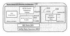
- the improvement to the prior art illustrated in FIG. 1is the inclusion of landmark-derived data, for example optical and SoOP RF landmarks (referred to as SoOP data in the diagram) 200 and in the Kalman Navigation Filter block 210 .
- the innovationapplies the SLAM framework to serve as the basis for the EKF 210 allowing these new data sources to contribute to the state estimate.
- This navigation filterestimates PVT while controlling vector tracking loops 215 using GPS, inertial Navigation systems (“INS”) 205 and SoOP source data 200 .
- INSinertial Navigation systems
- FIG. 2shows a more detailed view of the functions of the present disclosure, including the distinct loops for tracking code phase 220 and carrier frequency 230 .
- the '134 Applicationdescribes one embodiment of the use of SoOP data, where multiple mobile nodes (agents), equipped with SDR-based receiving assets, and interconnected via a robust ad-hoc wireless network or collaborative server, cooperate to estimate each agent location.
- the use of SLAM techniqueswas previously known for optical navigation, but Applicant's extension of SLAM techniques to RF transmissions was previously unknown.
- cooperating agentsdiscover and make measurements on an arbitrary number of heterogeneous, unknown, unsynchronized and un-located SoOPs.
- Applicant's previous disclosure of the use of SLAM in the RF environmentcan include small robotic vehicles 300 which can navigate within the hallways of a building by receiving and processing RF signals received from cell towers 310 , WiFi 320 and TV broadcast SoOPs 330 .
- SoOP existence and measurementsare shared between agents to facilitate measurement making and to enable the simultaneous estimation of agent location, SoOP location, and synthetic inter-SoOP timing synchronization.
- FIG. 4illustrates the use of the Applicant's SMARTS (simultaneous mapping and relative timing using SoOPs) algorithm.
- SLAM engine 400estimates the location of nodes and SoOP transmitters in an iterative fashion based on the past location of the nodes and SoOPs, current ranging and inertial measurements. SoOP locations are stored in database 410 and are either apriori knowledge or estimated over time by SLAM engine 400 .
- a SoOP timing database 420is maintained which keeps track of the absolute and relative time measurements made on SoOPs at each node 430 .
- the data in SoOP timing data base 420is used by SoOP timing prediction 440 to synthetically synchronize SoOP timing to allow accurate ranging to be estimated and used in SLAM engine 400 .
- the discovery and identification of the SoOPscan use characteristics of the SoOP in the physical plane, control plane or user plane.
- the SoOP transmissionscan also include multiple input multiple output (“MIMO”) transmissions for a single physical SoOP.
- MIMOmultiple input multiple output
- the SoOPscan include femotocells, repeaters, in-building distributed antenna systems (“DAS”) and proximity or time-aiding beacons. These SoOPs are especially useful for indoor location applications.
- the interconnecting wireless networkcan include the WiFi standard or cellular radio standards such as GSM and UMTS using either the control or user plane.
- the transmitting end of the wireless communications linkcan also serve as a SoOP.
- One embodiment of the present disclosureimproves the overall performance of GNSS functionality (position, velocity, timing (“PVT”) accuracy, robustness, interference immunity) by tightly coupling measurements made from additional RF signals sources such as broadcast satellite transmissions, cross-link communications from other satellites, and terrestrial transmission sources.
- the frameworkis based on combining the prior art in GNSS signal processing and the cooperative wireless network-based localization and mapping.
- the present disclosureis directed to a novel method of an EKF navigation filter capable of controlling vector tracking loops for GNSS, and accepting measurements made from other RF-based (SoOPs) and mechanical (IMU) measurements. While the prior art received input from navigation satellites and mechanical navigational measurements, prior art systems did not receive inputs from SoOPs.
- a methodimproves upon the prior art vector tracking and outside measurement source functionality previously described.
- the Applicant's previous patent applicationsdescribed a cooperative wireless network-based localization and mapping system using cooperative agents who use measurements based on radio ranging, other non-radio sources (for example laser and ultrasonic), and mechanical sensors (i.e. IMU) in a joint statistical filter (EKF) to estimate all node positions and the positions of the “landmarks” in the environment.
- EKFjoint statistical filter
- the early prior art work in this areawas single agent-based, used only optical landmarks and was titled conventionally referred to as Simultaneous Localization and Measurement (SLAM).
- SLAMSimultaneous Localization and Measurement
- the Applicantpreviously extended this technology to include multiple or cooperating agents (MA-SLAM or CSLAM), and radio-based landmarks.
- MA-SLAM or CSLAMmultiple or cooperating agents
- the Applicant's navigational systems disclosed in the '134 Applicationallows heterogeneous mixes of unsynchronized RF signals of opportunity (SoOP) combinations and quantities (without reference stations or precise knowledge of existence or locations for the SoOPs) to produce agent location data to an accuracy of a few meters.
- SoOPunsynchronized RF signals of opportunity
- METEORMulti-sourcE navigaTion using cooperative vEctOr tRacking
- features of this algorithmutilize components of the previously describe vector-tracking frequency and delay lock loop architecture, the cooperative SLAM/EKF framework for simultaneously tracking dynamic trajectory receivers and emitters, and the SMARTS technique for tracking unsynchronized signals of opportunity.
- features of the METEOR algorithminclude:
- FIG. 5illustrates a high-level architecture of one embodiment of the METEOR algorithm, and how it is evaluated through simulation.
- Databases ( 500 , 505contain information including GPS signal data with appropriate time varying delay and Doppler shift which is indicative of the underlying relative positions and velocities between the emitters (GPS signals and SoOP signals) and the receiver.
- digitized signal data 510is passed to the vector tracking loops 520 which are established for each unique emitter source.
- the tracking loops ( 520 )provide error terms ⁇ k for each of the k loops, from which pseudoranges ⁇ k are computed 530 .
- the pseudorangesare passed to the SLAM/EKF engine 540 , from which the receiver state vector s k is updated based on the current measurements and the model predictions.
- tracking loop corrections ⁇ k 550are computed which are fed back into the tracking loops.
- the updated SoOP position and timing estimates ⁇ k 560can be fed into the database which tracks the SoOP positions.
- VTL navigation systemshave been widely accepted as a suitable navigation algorithm for the tracking portion in GPS-based navigation.
- the GPS receiverPrior to tracking, the GPS receiver must acquire the satellites and from this initial position estimate, attempt to continue to track the satellites over time. The only actual difference between tracking and acquisition is the correlation period used. For acquisition, typically a short correlation period of 10 ms or less is used since the navigation data bit-periods (20 ms period), which cause phase reversals, is unknown. Extending the correlation beyond half of a bit period would cause poor correlation due to a mid-correlation window phase reversal.
- position and navigation data bitsare recovered, which allow longer duration averaging to be used in the tracking mode.
- Increasing the tracking durationlowers the noise power, thus allowing the receiver to continue to produce position estimates in the presence of low SNR.
- the receiveronce in tracking mode, it is possible for the receiver to periodically lose satellite reception and recover the signal at a later time without resorting back to acquisition mode based on the predicted delay and frequency provided by the estimated receiver position.
- the acquisition component of a VTL or conventional receiveris the same, in which a matched filter is processed in time and frequency against known transmitted signals, such as C/A codes in the GPS case.
- a matched filteris processed in time and frequency against known transmitted signals, such as C/A codes in the GPS case.
- use of the METEOR method with this embodimentimproves acquisition performance since initial position and time could be estimated from SoOP sources.
- METEOReffectively enters the higher-sensitivity tracking mode without actually requiring a conventional GPS acquisition stage as in the prior art.
- An important feature of this embodimentis the ability to derive accurate timing from the SoOP sources.
- even acquisition of a single satellitewould provide this information, allowing the receiver to switch to tracking mode more quickly and in otherwise impossible conditions for even a VTL-based GPS receiver.
- tracking performance of the METEOR methodis improved over conventional VTL in several aspects scenarios.
- the derivation of the METEOR methodillustrates the improvements over the Applicant's previously disclosed SMARTS algorithm.
- the METEOR methodefficiently represents and manipulates all clock biases and drifts in the context of the EKF state vector.
- This sectionexpands on the derivation of generic range and range-difference measurement EKF, and applies it specifically to the GPS and SoOP problem. GPS is discussed here, although the derivation can apply to any GNSS system.
- This derivationfills in a key deficiency in the prior art methods by deriving a EKF variant which combines the inputs from GPS and SoOP sources.
- the use of an EFK in the navigation contextis known as shown by J. J.
- PVT differencesPosition, Velocity, Time differences
- IMUinertial measurement units
- time indicesare denoted by the subscript k where the time instants are separated by a specified time at, which typically in this analysis is set to 1 second.
- the derivationwill be described with respect to a state vector s k and a measurement vector m k .
- the state vectoris a tall vector composed of positional information, positional rate of change with respect to time (velocity component) information, GPS clock bias and clock bias rate of change with respect to time (clock drift rate).
- the state vectorcan then be written as:
- the first three components of the vectorare the positional components in three dimensions. The next three are the rate of change of these components.
- the seventh componentis the clock bias and the lowermost component is the rate of change of the clock bias.
- the measurement vectoris also a tall vector and is composed of three components. The first is the set of computed pseudo-ranges to a fixed set of GPS satellites.
- the third measurement vector componentis the set of ranges computed to the SoOP sources.
- the only measurement feeding into the EKF from the correlatorsis the set of pseudo-ranges.
- the state update matrix F kcan be written as:
- h 1(s, v k ) can be approximated by the exact pseudo-range calculation given by ⁇ (x k )+v k where ⁇ (x k ) is the function that converts the state information into pseudo-ranges; and similarly for h 2 (s k , v k ) where a direct calculation of the measurements to the SoOPs is possible given the state (or estimated state). Generally speaking both of these functions are non-linear.
- the GPS clock at the receiveris considered to random walk with update equation:
- the clock parametersare in units of meters and meters per second.
- the random walk of the clock used in our simulationsis based on the clock update and covariance matrices given above.
- the clock update and the relevant covariance matrixare embedded in the matrices F k and Q k that have been previously discussed.
- Other models for the clock behaviorcan be easily considered in the same framework. estimated state). Generally speaking both of these functions are non-linear.
- the measurement vectorcan be linearized around some start state x k 0 with zero noise level to give m k ⁇ h ( s k 0 )+ H k ( s k ⁇ s k 0 )+ I k v k 10)
- H k⁇ h ⁇ ( s , v ) ⁇ s evaluated at (s k 0 , 0) and
- M kthe entirety of past measurements inclusive of m k similar to the definition of M k ⁇ 1 .
- s kthe entirety of past measurements inclusive of m k
- M k ⁇ 1the conditional estimate s k + ⁇ E[s k /M k ] and similarly, s k ⁇ ⁇ E[s k /M k ⁇ 1 ].
- the EKFcan continue to be updated, successfully maintaining the needed linearity as long as the estimated state is close enough to the actual state and a sufficient number of measurements made are close enough to the measurements corresponding to tracking the state. For this to hold up then the measurement vector, or at least some sufficient number of the measurements, must closely represent the proper measurements given the state. This is where the interaction between the navigation aspect of the problem and the tracking aspect exhibits itself. There must thus be some input from the navigation module to the tracking module that permits the tracking module to turn around and provide a measurement vector that has adjusted for the changes in the state vector of the navigation module.
- One way to achieve this endis to suitably adjust the PN sequences in a manner reflective of the state updates. In Lashley prior art, this is achieved this by passing a predicted input to the tracking module that allows the tracking module to update its PN sequences (possibly in terms of clock frequency but certainly in terms of clock phase).
- an improvement over the prior art feedback loopis to have the PN correlators maintain a quality measure along with the pseudo-range measurements.
- the quality measure for any given PN correlatordrops below a specified threshold, that pseudo-range is dynamically dropped from the EKF measurement inputs.
- the quality measureis below threshold, the EKF state estimate is used to derive an estimate of the proper alignment required at the PN correlators and this estimated alignment is maintained until the quality measure exceeds the threshold.
- the quality measureis above the threshold the PN correlators do not take input from the estimated EKF state to maintain synchronism; rather they operate autonomously.
- Hyper-time processingIn another embodiment of the METEOR method, another significant improvement over the prior art is the computational savings associated with a mode of operating in which the navigation receiver periodically reverts to an idle state once acquisition is completed and tracking has begun. In one embodiment, after a configurable period of time, the receiver may resume processing and continue where it left off, provided that good estimates of PVT of the mobile device have already been achieved. In prior art, it was common to use ultra-tight coupling/vector tracking approaches to improve the performance of GNSS receivers when GPS reception conditions are impaired. In those cases, the vector tracking filters operated with the assistance of the EKF continuously through the GPS reception impairment.
- the vector tracking loop computations of the present disclosuremay be intentionally stopped (the EKF computations continue) to reduce computational load.
- the vector tracking architectureis able to pick up from where it left of at any later time without reacquisition.
- the idle period durationmay be a function of the dynamics of the emitter platforms, the receiver platform, and the quality of the tracking.
- the vector tracking filtersmay be updated based on only the mechanical navigation measurements provided by a local inertial measurement unit and/or SoOP data during the idle period, which would serve to further stabilize the state prediction once new receiver measurements become available.
- This alternative embodimentwould still offer considerable processing savings due to the fact that the correlator functions would be disabled during the idle period, which is what consumes the majority of the processing resources when compared to simply updating the tracking filter states.
- FIG. 6illustrates the operation of the Hyper-time method.
- the acquisition process 600 and/or SoOP/inertial measurements used in the EKF 610provide the control for the oscillators in the vector tracking loops 620 .
- the vector tracking loopsoperate at some duty cycle.
- the duty cycleis illustrated in the timeline at the top of the figure with the active period being represented by the small time increment 630 and the idle period being represented by the long time period 640 .
- Many methodscould be used to determine the vector filter duty cycle including a fixed period, or a variable period based on a number of different criteria including quality of the current estimates, power budgets, location/accuracy requirements, etc.
- a high level depiction of this processis shown in the three boxes 650 where first a process determines the sleep time (no processing) 652 , a second process puts the tracking loops to sleep 654 , and a third process wakes the loops to again begin processing based on a wake up criteria 656 .
- FIG. 7An illustration is shown in FIG. 7 of the migration from dedicated silicon of the prior art to SDR basis for a PNT system. Referring to the figure, the key functions of a prior art dedicated silicon implementation are shown in 700 .
- One embodiment of the present disclosure of an SDR-based platformis shown in 710 with the software-based functions of tracking and PVT estimation shown in 720 and 740 .
- SoOP-related processing(as well as other applications like communications) are shown in 730 . Note that in this architecture, new signal processing methods such as those described in the present invention can be easily added to the PNT functionality application operating on the SDR platform.
- a key recent development in SDR usageis the merging of applications (for example communications and navigation) onto common SDR platforms. This is well underway in the smart phone industry where data from multiple communications services (cellular, WiFi, bluetooth, etc.), and sensing technologies (camera phones, IMUS, etc.) are processed in common general purpose processor/graphic processor unit/digital signal processor (GPP/GPU/DSP) machines.
- GPS/GPU/DSPgeneral purpose processor/graphic processor unit/digital signal processor
- Nvidiahas recently unveiled its next generation smart phone processor which includes four 1.9 GHz Arm A15 CPU cores, 72 GPU cores, and an integrated Icera LTE/WCDMA “soft-modem” capable of 1.2 Trillion operations per second.
- the soft-modemcontains 8 programmable processors and replaces traditional designs that dedicate die space on the chip to specific protocol processing that cannot be modified or upgraded, and consume a significant amount of a smart phone power budget.
- the availability of SDR-type processing and access to other data sourcesprovides a means to significantly improve PNT performance in challenging propagation environments, and detect/mitigate interference, all while providing a platform that minimizes power consumption affording a robust navigational capability that was not available in the prior art.
- Embodiments of the subject matter and the functional operations described in this specificationcan be implemented in digital electronic circuitry, or in computer software, firmware, or hardware, including the structures disclosed in this specification and their structural equivalents, or in combinations of one or more of them.
- Embodiments of the subject matter described in this specificationcan be implemented as one or more computer program products, i.e., one or more modules of computer program instructions encoded on a tangible program carrier for execution by, or to control the operation of, data processing apparatus.
- the tangible program carriercan be a computer readable medium.
- the computer readable mediumcan be a machine-readable storage device, a machine-readable storage substrate, a memory device, or a combination of one or more of them.
- processorencompasses all apparatus, devices, and machines for processing data, including by way of example a programmable processor, a computer, or multiple processors or computers.
- the processorcan include, in addition to hardware, code that creates an execution environment for the computer program in question, e.g., code that constitutes processor firmware, a protocol stack, a database management system, an operating system, or a combination of one or more of them.
- a computer program(also known as a program, software, software application, script, or code) can be written in any form of programming language, including compiled or interpreted languages, or declarative or procedural languages, and it can be deployed in any form, including as a standalone program or as a module, component, subroutine, or other unit suitable for use in a computing environment.
- a computer programdoes not necessarily correspond to a file in a file system.
- a programcan be stored in a portion of a file that holds other programs or data (e.g., one or more scripts stored in a markup language document), in a single file dedicated to the program in question, or in multiple coordinated files (e.g., files that store one or more modules, sub programs, or portions of code).
- a computer programcan be deployed to be executed on one computer or on multiple computers that are located at one site or distributed across multiple sites and interconnected by a communication network.
- the processes and logic flows described in this specificationcan be performed by one or more programmable processors executing one or more computer programs to perform functions by operating on input data and generating output.
- the processes and logic flowscan also be performed by, and apparatus can also be implemented as, special purpose logic circuitry, e.g., an FPGA (field programmable gate array) or an ASIC (application specific integrated circuit).
- processors suitable for the execution of a computer programinclude, by way of example, both general and special purpose microprocessors, and any one or more processors of any kind of digital computer.
- a processorwill receive instructions and data from a read only memory or a random access memory or both.
- the essential elements of a computerare a processor for performing instructions and one or more data memory devices for storing instructions and data.
- a computerwill also include, or be operatively coupled to receive data from or transfer data to, or both, one or more mass storage devices for storing data, e.g., magnetic, magneto optical disks, or optical disks.
- mass storage devicesfor storing data, e.g., magnetic, magneto optical disks, or optical disks.
- a computerneed not have such devices.
- a computercan be embedded in another device, e.g., a mobile telephone, a personal digital assistant (PDA), a mobile audio or video player, a game console, a Global Positioning System (GPS) receiver, to name just a few.
- PDApersonal digital assistant
- GPSGlobal Positioning System
- Computer readable media suitable for storing computer program instructions and datainclude all forms data memory including non volatile memory, media and memory devices, including by way of example semiconductor memory devices, e.g., EPROM, EEPROM, and flash memory devices; magnetic disks, e.g., internal hard disks or removable disks; magneto optical disks; and CD ROM and DVD-ROM disks.
- semiconductor memory devicese.g., EPROM, EEPROM, and flash memory devices
- magnetic diskse.g., internal hard disks or removable disks
- magneto optical diskse.g., CD ROM and DVD-ROM disks.
- the processor and the memorycan be supplemented by, or incorporated in, special purpose logic circuitry.
- embodiments of the subject matter described in this specificationcan be implemented on a computer having a display device, e.g., a CRT (cathode ray tube) or LCD (liquid crystal display) monitor, for displaying information to the user and a keyboard and a pointing device, e.g., a mouse or a trackball, by which the user can provide input to the computer.
- a display devicee.g., a CRT (cathode ray tube) or LCD (liquid crystal display) monitor
- keyboard and a pointing devicee.g., a mouse or a trackball
- Other kinds of devicescan be used to provide for interaction with a user as well; for example, input from the user can be received in any form, including acoustic, speech, or tactile input.
- Embodiments of the subject matter described in this specificationcan be implemented in a computing system that includes a back end component, e.g., as a data server, or that includes a middleware component, e.g., an application server, or that includes a front end component, e.g., a client computer having a graphical user interface or a Web browser through which a user can interact with an implementation of the subject matter described is this specification, or any combination of one or more such back end, middleware, or front end components.
- the components of the systemcan be interconnected by any form or medium of digital data communication, e.g., a communication network. Examples of communication networks include a local area network (“LAN”) and a wide area network (“WAN”), e.g., the Internet.
- LANlocal area network
- WANwide area network
- the computing systemcan include clients and servers.
- a client and serverare generally remote from each other and typically interact through a communication network.
- the relationship of client and serverarises by virtue of computer programs running on the respective computers and having a client-server relationship to each other.
Landscapes
- Engineering & Computer Science (AREA)
- Radar, Positioning & Navigation (AREA)
- Remote Sensing (AREA)
- Physics & Mathematics (AREA)
- General Physics & Mathematics (AREA)
- Computer Networks & Wireless Communication (AREA)
- Position Fixing By Use Of Radio Waves (AREA)
Abstract
Description
- Utilizing measurements from multiple emitter classes including GNSS and other signals of opportunity
- Simultaneously tracking each navigational satellite in a vector-based EKF, which provides robustness against periodic loss of signals and rapid re-acquisition
- Jointly computing emitter PVT parameters of emitter sources, along with receive PVT estimates
- Exploiting inter-communication between cooperative receivers to jointly estimate unknown emitter characteristics.
- 1) In prior art systems, GPS blockage could result in only a subset of satellites to be received on one side of the earth, resulting in poor satellite geometry, or high DOP (Dilution of Precision). With the current disclosure, using SoOPs to augment GPS, could improve DOP, even if the measurements themselves are inferior to GPS accuracy, thereby improving overall position accuracy.
- 2) Along the same lines as 1), as the number of measurements used to estimate PVT increases, overall position and velocity accuracy improves even if the additional measurements have inferior accuracy when compared with GPS.
- 3) The present disclosure allows the use of GPS pseudo ranges even where there are fewer than four measured satellites, unlike with a conventional GPS receiver. Because GPS satellites, in the absence of high multipath, offer high accuracy position data, these provides some benefit to the overall position estimate when paired with lower-quality measurement data that could be derived from SoOPs.
The first three components of the vector are the positional components in three dimensions. The next three are the rate of change of these components. The seventh component is the clock bias and the lowermost component is the rate of change of the clock bias. The measurement vector is also a tall vector and is composed of three components. The first is the set of computed pseudo-ranges to a fixed set of GPS satellites. The third measurement vector component is the set of ranges computed to the SoOP sources. In one embodiment, the only measurement feeding into the EKF from the correlators is the set of pseudo-ranges. One can also visualize a set of correlators that feeds the EKF with the ranges to the SoOP sources if in fact we wish to view both sets of measurements being derived within a similar mathematical framework.
sk+1=Fksk+Gkwk 2)
Where Fkexpresses the state update in a matrix with known and in this analysis generally fixed terms. The suffix k allows for the time dependence nature of the state vector. The state update matrix Fkcan be written as:
The matrix Gkis a known matrix (possibly approximated as a unit matrix of the same dimensions) and wkis an independent zero mean Gaussian white process with covariance
E(wkwkT)=Qk 4)
The measurement vectors are a non-linear function of the state:
mk=h(sk, vk) 5)
In which vkis an independent zero mean Gaussian white process with covariance
E(vkvKT)=Rk 6)
The measurement vector is composed of three components:
where the first is the set of computed pseudo-ranges and the second is the set of ranges to the sources of the SOOPs. Also note that the function h1(s, vk) can be approximated by the exact pseudo-range calculation given by φ(xk)+vkwhere φ(xk) is the function that converts the state information into pseudo-ranges; and similarly for h2(sk, vk) where a direct calculation of the measurements to the SoOPs is possible given the state (or estimated state). Generally speaking both of these functions are non-linear.
where the noise vector wckhas a covariance matrix given by
The noise spectral amplitudes Sband Sfcan be related to the Allan variance parameters. The approximations we use for these are h_0=2e−19; h_2=2e−20; Sb=8π2; h_2=Sf2*h_0. The clock parameters are in units of meters and meters per second. The random walk of the clock used in our simulations is based on the clock update and covariance matrices given above. We note that the clock update and the relevant covariance matrix are embedded in the matrices Fkand Qkthat have been previously discussed. Other models for the clock behavior can be easily considered in the same framework. estimated state). Generally speaking both of these functions are non-linear.
mk≅h(sk0)+Hk(sk−sk0)+Ikvk 10)
Where
evaluated at (sk0, 0) and
evaluated at (sk0, 0). We note that with this linearization, the equations for the state update and the measurement are now identical to those for a linear Kalman filter except for the bias terms. Thus in the proximity of a solution to the state and measurement equations, a linear biased model can be used to define the system operation. In particular we can note that the conditional covariance of mkgiven the entirety of past measurements Mk−1=[mk−1, mk−2, . . . ] is unaffected by the bias terms and is thus dependent only on Hk. In general let us denote Mkas the entirety of past measurements inclusive of mksimilar to the definition of Mk−1. Let us define the conditional estimate sk+≡E[sk/Mk] and similarly, sk−≡E[sk/Mk−1].
Also define the covariance matrices
Pk+≡Cov(sk/Mk) andPk−≡Cov(sk/Mk−1) 11)
The conditional vector [(sk/Mk)T/Mk−1] is then Gaussian with mean [sk−Hksk+]Tand covariance matrix
where
Uk=HkPk+HkT+Rk 12)
It is then straightforward to show that (xk/Zk) is Gaussian with mean
sk+=sk−+Pk−HkTUk−1(mk−h(sk, 0)) 13)
and covariance matrix
Pk+=Pk−+Pk−HkTUk−1HkPk− 14)
One reason for the weaker performance of the prior art delta-PVT model may be due to the fact that one cannot use the exact non-linear calculation h(sk, 0) and must resort to once again using the matrix Hk. Thus, in one embodiment, the latter matrix is used both in the measurement linearization and in the measurement update thus resulting in a double use of the same approximation. In addition most noise terms are also differenced resulting in larger variances.
sk+1−=E[sk+1/Zk]=Fksk+ 15)
and
PK+1−=FkPk+FkT+GkQkGkT 16)
where these last two equations represent the time update step of the EKF. There is some variation in the literature as to the order in which these updates are applied. In one embodiment the state update can be applied first and the measurement update second (this only matters in terms of aligning the estimated state to the actual state for comparison purposes).
Claims (12)
Priority Applications (1)
| Application Number | Priority Date | Filing Date | Title |
|---|---|---|---|
| US14/328,180US9739891B2 (en) | 2011-09-30 | 2014-07-10 | System and method of using measurements of opportunity with vector tracking filters for improved navigation |
Applications Claiming Priority (4)
| Application Number | Priority Date | Filing Date | Title |
|---|---|---|---|
| US13/250,134US9588218B2 (en) | 2010-09-30 | 2011-09-30 | System and method for robust navigation and geolocation using measurements of opportunity |
| US13/909,824US9594170B2 (en) | 2011-09-30 | 2013-06-04 | Performance improvements for measurement of opportunity geolocation/navigation systems |
| US201361844605P | 2013-07-10 | 2013-07-10 | |
| US14/328,180US9739891B2 (en) | 2011-09-30 | 2014-07-10 | System and method of using measurements of opportunity with vector tracking filters for improved navigation |
Related Parent Applications (1)
| Application Number | Title | Priority Date | Filing Date |
|---|---|---|---|
| US13/250,134Continuation-In-PartUS9588218B2 (en) | 2010-09-30 | 2011-09-30 | System and method for robust navigation and geolocation using measurements of opportunity |
Publications (2)
| Publication Number | Publication Date |
|---|---|
| US20150048972A1 US20150048972A1 (en) | 2015-02-19 |
| US9739891B2true US9739891B2 (en) | 2017-08-22 |
Family
ID=52466460
Family Applications (1)
| Application Number | Title | Priority Date | Filing Date |
|---|---|---|---|
| US14/328,180Active2032-09-20US9739891B2 (en) | 2011-09-30 | 2014-07-10 | System and method of using measurements of opportunity with vector tracking filters for improved navigation |
Country Status (1)
| Country | Link |
|---|---|
| US (1) | US9739891B2 (en) |
Cited By (5)
| Publication number | Priority date | Publication date | Assignee | Title |
|---|---|---|---|---|
| US20180352434A1 (en)* | 2017-06-05 | 2018-12-06 | Renesas Electronics Corporation | Wireless communication system, beacon device, information processing terminal, and beacon device authentication method |
| US10991117B2 (en) | 2018-12-23 | 2021-04-27 | Samsung Electronics Co., Ltd. | Performing a loop closure detection |
| US20220171077A1 (en)* | 2019-04-15 | 2022-06-02 | The Regents Of The University Of California | Simultaneous tracking and navigation using leo satellite signals |
| EP4016110A1 (en)* | 2020-12-18 | 2022-06-22 | The Boeing Company | Position, navigation and timing system architecture based on signals of opportunity |
| US12270916B2 (en) | 2019-07-24 | 2025-04-08 | Echo Ridge Llc | System and method for aiding data processing for signals of opportunity-based assured position, navigation and timing (PNT) |
Families Citing this family (9)
| Publication number | Priority date | Publication date | Assignee | Title |
|---|---|---|---|---|
| EP2940490B1 (en)* | 2014-04-30 | 2024-05-29 | U-blox AG | Determining clock-drift using signals of opportunity |
| US20210199815A1 (en)* | 2016-02-12 | 2021-07-01 | The Regents Of The University Of California | Sdr for navigation with cellular cdma signals |
| CN106443726A (en)* | 2016-08-30 | 2017-02-22 | 西安航天华迅科技有限公司 | GNSS vector tracking loop based on pre-filtering, and implementation method for GNSS vector tracking loop |
| US11366236B2 (en)* | 2016-09-22 | 2022-06-21 | The Regents Of The University Of California | Signals of opportunity aided inertial navigation |
| US20190041527A1 (en)* | 2017-08-03 | 2019-02-07 | The Charles Stark Draper Laboratory, Inc. | Gps-based navigation system using a nonlinear discrete-time tracking filter |
| CN108919311B (en)* | 2018-04-18 | 2022-07-15 | 青岛杰瑞自动化有限公司 | Anti-interference method for Beidou navigation system |
| US10234538B1 (en) | 2018-09-24 | 2019-03-19 | Science Applications International Corporation | System and method for dismounted assured position, navigation and timing (DAPNT) |
| US12235367B2 (en)* | 2022-09-27 | 2025-02-25 | Bae Systems Information And Electronic Systems Integration Inc. | Navigation system with embedded software defined radio |
| CN117031453A (en)* | 2023-10-08 | 2023-11-10 | 中国科学院空天信息创新研究院 | Low orbit satellite opportunistic signal pseudo-range calculation method |
Citations (63)
| Publication number | Priority date | Publication date | Assignee | Title |
|---|---|---|---|---|
| US5794128A (en) | 1995-09-20 | 1998-08-11 | The United States Of America As Represented By The Secretary Of The Army | Apparatus and processes for realistic simulation of wireless information transport systems |
| US5917449A (en) | 1995-06-07 | 1999-06-29 | Sanconix Inc. | Enhanced position calculation |
| US6094168A (en) | 1995-09-19 | 2000-07-25 | Cambridge Positioning Systems Ltd. | Position determining system |
| US6275705B1 (en) | 1995-12-22 | 2001-08-14 | Cambridge Positioning Systems Ltd. | Location and tracking system |
| US6313789B1 (en)* | 1998-06-10 | 2001-11-06 | Topcon Positioning Systems, Inc. | Joint tracking of the carrier phases of the signals received from different satellites |
| US6393292B1 (en) | 1999-04-13 | 2002-05-21 | Ching-Fang Lin | Method of transmitting positions data via cellular communication system |
| US20020160717A1 (en) | 2001-01-16 | 2002-10-31 | Anders Persson | Chamber for and a method of processing electronic devices and the use of such a chamber |
| US6492945B2 (en)* | 2001-01-19 | 2002-12-10 | Massachusetts Institute Of Technology | Instantaneous radiopositioning using signals of opportunity |
| US6522890B2 (en) | 1995-12-22 | 2003-02-18 | Cambridge Positioning Systems, Ltd. | Location and tracking system |
| US6571082B1 (en) | 1999-10-29 | 2003-05-27 | Verizon Laboratories Inc. | Wireless field test simulator |
| US6865395B2 (en) | 2002-08-08 | 2005-03-08 | Qualcomm Inc. | Area based position determination for terminals in a wireless network |
| US20050085223A1 (en) | 2003-10-20 | 2005-04-21 | Accton Technology Corporation | System and method for multi-path simulation |
| US20050197769A1 (en)* | 2004-03-02 | 2005-09-08 | Honeywell International Inc. | Personal navigation using terrain-correlation and/or signal-of-opportunity information |
| US20050200525A1 (en) | 2002-06-17 | 2005-09-15 | Duffett-Smith Peter J. | Radio positioning systems |
| US20050260962A1 (en) | 2004-05-20 | 2005-11-24 | Shahbaz Nazrul | Systems and methods for testing signal processing control |
| US6978131B1 (en) | 1999-06-14 | 2005-12-20 | Anritsu Limited | Testing mobile phones |
| US7035650B1 (en) | 2000-06-14 | 2006-04-25 | International Business Machines Corporation | System and method for providing directions |
| US20060094365A1 (en) | 2002-12-24 | 2006-05-04 | Matsushita Electric Industrial Co. Ltd | Channel simulator and wireless apparatus evaluation method |
| US20060128315A1 (en) | 2002-07-18 | 2006-06-15 | Belcea John M | System and method for improving the quality of range measurement based upon historical data |
| US20060148429A1 (en) | 2002-12-24 | 2006-07-06 | Matsushita Electric Industrial Co., Ltd. | Transmission path simulation method and transmission path simulator |
| US20060174162A1 (en) | 2005-02-03 | 2006-08-03 | Satyam Computer Services Ltd. | System and method for self-testing of mobile wireless devices |
| US20060229018A1 (en) | 2005-04-12 | 2006-10-12 | Azimuth Systems, Inc. | Apparatus and method for use in testing wireless devices |
| US20060229020A1 (en) | 2005-04-12 | 2006-10-12 | Azimuth Systems Inc. | Modular wireless test architecture and method |
| US20070019769A1 (en) | 2003-06-30 | 2007-01-25 | Green Marilynn P | Apparatus, and associated method, for testing a mobile terminal in test conditions that emulate an operating environment |
| US7171345B2 (en) | 2002-03-22 | 2007-01-30 | Sun Microsystems, Inc. | System and method for simulating an input to a telematics system |
| US20070072552A1 (en) | 2003-05-19 | 2007-03-29 | Elias Jonsson | Determination of a channel estimate of a transmission channel |
| US20070127559A1 (en) | 2005-12-02 | 2007-06-07 | Chang Paul C | Systems and methods for testing the performance of and simulating a wireless communication device |
| US20070223571A1 (en) | 2006-03-27 | 2007-09-27 | Viss Marlin E | Decision-feedback equalizer simulator |
| WO2007113086A1 (en) | 2006-04-04 | 2007-10-11 | Cambridge Positioning Systems Limited | Associating a universal time with a received signal |
| US20080026748A1 (en) | 2006-07-31 | 2008-01-31 | Thomas Alexander | Method and apparatus for wireless mobility measurements |
| US20080057873A1 (en) | 2005-08-29 | 2008-03-06 | International Business Machines Corporation | Method of indoor radio planning |
| US20080084951A1 (en) | 2006-10-06 | 2008-04-10 | Helen Chen | Systems and methods for receiving multiple input, multiple output signals for test and analysis of multiple-input, multiple-output systems |
| US7398086B2 (en) | 2001-04-27 | 2008-07-08 | Thales | System and method to locate radiomobiles outside the coverage of a cellular network |
| WO2008119635A1 (en) | 2007-03-29 | 2008-10-09 | Cambridge Positioning Systems Limited | Determining the change in time at a mobile terminal |
| US20090094492A1 (en) | 2007-10-04 | 2009-04-09 | Veriwave, Inc. | Channel impairment emulator systems and methods |
| US20090113245A1 (en) | 2007-10-30 | 2009-04-30 | Teradyne, Inc. | Protocol aware digital channel apparatus |
| US20090213828A1 (en) | 2006-12-07 | 2009-08-27 | Zulutime, Llc | Wireless local area network-based position locating systems and methods |
| US20090233621A1 (en) | 2006-12-07 | 2009-09-17 | Zulutime, Llc | Systems and methods for locating a mobile device within a cellular system |
| WO2009112293A1 (en) | 2008-03-10 | 2009-09-17 | Cambridge Positioning Systems Limited | Finding the position of a mobile terminal |
| US20090281729A1 (en)* | 2006-09-18 | 2009-11-12 | Cambridge Postioning Systems Limited | Integrated Mobile Terminal Navigation |
| US7620368B2 (en) | 2004-03-19 | 2009-11-17 | Qualcomm, Incorporated | Systems and techniques for testing a wireless communications device |
| US20100062722A1 (en) | 2008-09-09 | 2010-03-11 | Whirlpool Corporation | System and method for determining path loss in a use environment |
| US20100099361A1 (en) | 2007-04-11 | 2010-04-22 | Telefonaktiebolaget Lm Ericsson (Publ) | Arrangement and method for simulating a radio access network |
| US7773995B2 (en) | 2005-04-18 | 2010-08-10 | Motorola, Inc. | Method and apparatus for utilizing RF signals to create a site specific representation of an environment |
| US20110037650A1 (en)* | 2009-08-13 | 2011-02-17 | Gary Lennen | Method and apparatus for reducing power consumption in gnss receivers |
| US20110124295A1 (en) | 2009-11-24 | 2011-05-26 | Spirent Communications, Inc. | Methods and systems for testing cell phones with multiple antennas |
| US20110136457A1 (en) | 2008-05-15 | 2011-06-09 | Zhong Yu | System and method for the wireless terminal receiving sensitivity performance test based on data mode |
| US8000656B1 (en) | 2006-12-19 | 2011-08-16 | Hewlett-Packard Development Company, L.P. | Apparatus and methods for performing calibration of a mobile computing device |
| US8018383B1 (en)* | 2010-06-08 | 2011-09-13 | Q-Track Corporation | Method and apparatus for determining location using signals-of-opportunity |
| US20110223869A1 (en) | 2008-11-04 | 2011-09-15 | Rohde & Schwarz Gmbh & Co. Kg | Method and device for testing a mobile-radio device by means of static channel simulation |
| US20110287721A1 (en) | 2009-02-13 | 2011-11-24 | Autotalks Ltd. | Dynamic rf matrix emulator |
| US20110306306A1 (en) | 2009-02-13 | 2011-12-15 | Spirent Communications, Inc. | Method and Apparatus for Virtual Desktop OTA |
| US8086187B1 (en) | 2007-09-11 | 2011-12-27 | Raytheon Company | Developing and analyzing a communication system |
| US8126453B2 (en) | 2008-10-09 | 2012-02-28 | Inventec Appliances Corp. | Radio frequency testing system and method of performing radio frequency test on a plurality of mobile communication devices |
| US20120071107A1 (en) | 2009-06-03 | 2012-03-22 | Elektrobit System Test Oy | Over-The-Air Test |
| US8229416B2 (en) | 2008-09-23 | 2012-07-24 | Ixia | Methods, systems, and computer readable media for stress testing mobile network equipment using a common public radio interface (CPRI) |
| US20120225624A1 (en) | 2011-03-02 | 2012-09-06 | Elektrobit System Test Oy | Over-the-Air Test |
| US8270910B2 (en) | 2006-09-15 | 2012-09-18 | Itron, Inc. | Embedded RF environmental evaluation tool to gauge RF transceivers performance need |
| US8332198B1 (en) | 2005-03-22 | 2012-12-11 | Advanced Micro Devices, Inc. | Data generation and collection from a real-time system for non-real-time software simulation |
| US8339142B2 (en) | 2010-01-22 | 2012-12-25 | Denso Corporation | System for diagnosing sensors to find out abnormality therein |
| US20130029608A1 (en) | 2011-07-28 | 2013-01-31 | Chih-Jen Kuo | Methods of calibrating a device under test to communicate wirelessly |
| US20130231060A1 (en) | 2004-10-25 | 2013-09-05 | Qualcomm Incorporated | Systems, methods and apparatus for determining a radiated performance of a wireless device |
| US20140051363A1 (en) | 2009-05-27 | 2014-02-20 | Echo Ridge Llc | Wireless transceiver test bed system and method |
- 2014
- 2014-07-10USUS14/328,180patent/US9739891B2/enactiveActive
Patent Citations (64)
| Publication number | Priority date | Publication date | Assignee | Title |
|---|---|---|---|---|
| US5917449A (en) | 1995-06-07 | 1999-06-29 | Sanconix Inc. | Enhanced position calculation |
| US6094168A (en) | 1995-09-19 | 2000-07-25 | Cambridge Positioning Systems Ltd. | Position determining system |
| US5794128A (en) | 1995-09-20 | 1998-08-11 | The United States Of America As Represented By The Secretary Of The Army | Apparatus and processes for realistic simulation of wireless information transport systems |
| US6522890B2 (en) | 1995-12-22 | 2003-02-18 | Cambridge Positioning Systems, Ltd. | Location and tracking system |
| US6275705B1 (en) | 1995-12-22 | 2001-08-14 | Cambridge Positioning Systems Ltd. | Location and tracking system |
| US6313789B1 (en)* | 1998-06-10 | 2001-11-06 | Topcon Positioning Systems, Inc. | Joint tracking of the carrier phases of the signals received from different satellites |
| US6393292B1 (en) | 1999-04-13 | 2002-05-21 | Ching-Fang Lin | Method of transmitting positions data via cellular communication system |
| US6978131B1 (en) | 1999-06-14 | 2005-12-20 | Anritsu Limited | Testing mobile phones |
| US6571082B1 (en) | 1999-10-29 | 2003-05-27 | Verizon Laboratories Inc. | Wireless field test simulator |
| US7035650B1 (en) | 2000-06-14 | 2006-04-25 | International Business Machines Corporation | System and method for providing directions |
| US20020160717A1 (en) | 2001-01-16 | 2002-10-31 | Anders Persson | Chamber for and a method of processing electronic devices and the use of such a chamber |
| US6492945B2 (en)* | 2001-01-19 | 2002-12-10 | Massachusetts Institute Of Technology | Instantaneous radiopositioning using signals of opportunity |
| US7398086B2 (en) | 2001-04-27 | 2008-07-08 | Thales | System and method to locate radiomobiles outside the coverage of a cellular network |
| US7171345B2 (en) | 2002-03-22 | 2007-01-30 | Sun Microsystems, Inc. | System and method for simulating an input to a telematics system |
| US20050200525A1 (en) | 2002-06-17 | 2005-09-15 | Duffett-Smith Peter J. | Radio positioning systems |
| US20060128315A1 (en) | 2002-07-18 | 2006-06-15 | Belcea John M | System and method for improving the quality of range measurement based upon historical data |
| US6865395B2 (en) | 2002-08-08 | 2005-03-08 | Qualcomm Inc. | Area based position determination for terminals in a wireless network |
| US20060094365A1 (en) | 2002-12-24 | 2006-05-04 | Matsushita Electric Industrial Co. Ltd | Channel simulator and wireless apparatus evaluation method |
| US20060148429A1 (en) | 2002-12-24 | 2006-07-06 | Matsushita Electric Industrial Co., Ltd. | Transmission path simulation method and transmission path simulator |
| US20070072552A1 (en) | 2003-05-19 | 2007-03-29 | Elias Jonsson | Determination of a channel estimate of a transmission channel |
| US20070019769A1 (en) | 2003-06-30 | 2007-01-25 | Green Marilynn P | Apparatus, and associated method, for testing a mobile terminal in test conditions that emulate an operating environment |
| US20050085223A1 (en) | 2003-10-20 | 2005-04-21 | Accton Technology Corporation | System and method for multi-path simulation |
| US20050197769A1 (en)* | 2004-03-02 | 2005-09-08 | Honeywell International Inc. | Personal navigation using terrain-correlation and/or signal-of-opportunity information |
| US7620368B2 (en) | 2004-03-19 | 2009-11-17 | Qualcomm, Incorporated | Systems and techniques for testing a wireless communications device |
| US20050260962A1 (en) | 2004-05-20 | 2005-11-24 | Shahbaz Nazrul | Systems and methods for testing signal processing control |
| US20130231060A1 (en) | 2004-10-25 | 2013-09-05 | Qualcomm Incorporated | Systems, methods and apparatus for determining a radiated performance of a wireless device |
| US20060174162A1 (en) | 2005-02-03 | 2006-08-03 | Satyam Computer Services Ltd. | System and method for self-testing of mobile wireless devices |
| US8332198B1 (en) | 2005-03-22 | 2012-12-11 | Advanced Micro Devices, Inc. | Data generation and collection from a real-time system for non-real-time software simulation |
| US20060229018A1 (en) | 2005-04-12 | 2006-10-12 | Azimuth Systems, Inc. | Apparatus and method for use in testing wireless devices |
| US20060229020A1 (en) | 2005-04-12 | 2006-10-12 | Azimuth Systems Inc. | Modular wireless test architecture and method |
| US7773995B2 (en) | 2005-04-18 | 2010-08-10 | Motorola, Inc. | Method and apparatus for utilizing RF signals to create a site specific representation of an environment |
| US20080057873A1 (en) | 2005-08-29 | 2008-03-06 | International Business Machines Corporation | Method of indoor radio planning |
| US20070127559A1 (en) | 2005-12-02 | 2007-06-07 | Chang Paul C | Systems and methods for testing the performance of and simulating a wireless communication device |
| US20070223571A1 (en) | 2006-03-27 | 2007-09-27 | Viss Marlin E | Decision-feedback equalizer simulator |
| WO2007113086A1 (en) | 2006-04-04 | 2007-10-11 | Cambridge Positioning Systems Limited | Associating a universal time with a received signal |
| US20080026748A1 (en) | 2006-07-31 | 2008-01-31 | Thomas Alexander | Method and apparatus for wireless mobility measurements |
| US8270910B2 (en) | 2006-09-15 | 2012-09-18 | Itron, Inc. | Embedded RF environmental evaluation tool to gauge RF transceivers performance need |
| US20090281729A1 (en)* | 2006-09-18 | 2009-11-12 | Cambridge Postioning Systems Limited | Integrated Mobile Terminal Navigation |
| US20080084951A1 (en) | 2006-10-06 | 2008-04-10 | Helen Chen | Systems and methods for receiving multiple input, multiple output signals for test and analysis of multiple-input, multiple-output systems |
| US20090233621A1 (en) | 2006-12-07 | 2009-09-17 | Zulutime, Llc | Systems and methods for locating a mobile device within a cellular system |
| US20090213828A1 (en) | 2006-12-07 | 2009-08-27 | Zulutime, Llc | Wireless local area network-based position locating systems and methods |
| US8000656B1 (en) | 2006-12-19 | 2011-08-16 | Hewlett-Packard Development Company, L.P. | Apparatus and methods for performing calibration of a mobile computing device |
| WO2008119635A1 (en) | 2007-03-29 | 2008-10-09 | Cambridge Positioning Systems Limited | Determining the change in time at a mobile terminal |
| US20100099361A1 (en) | 2007-04-11 | 2010-04-22 | Telefonaktiebolaget Lm Ericsson (Publ) | Arrangement and method for simulating a radio access network |
| US8086187B1 (en) | 2007-09-11 | 2011-12-27 | Raytheon Company | Developing and analyzing a communication system |
| US20090094492A1 (en) | 2007-10-04 | 2009-04-09 | Veriwave, Inc. | Channel impairment emulator systems and methods |
| US20090113245A1 (en) | 2007-10-30 | 2009-04-30 | Teradyne, Inc. | Protocol aware digital channel apparatus |
| WO2009112293A1 (en) | 2008-03-10 | 2009-09-17 | Cambridge Positioning Systems Limited | Finding the position of a mobile terminal |
| US20110136457A1 (en) | 2008-05-15 | 2011-06-09 | Zhong Yu | System and method for the wireless terminal receiving sensitivity performance test based on data mode |
| US20100062722A1 (en) | 2008-09-09 | 2010-03-11 | Whirlpool Corporation | System and method for determining path loss in a use environment |
| US8229416B2 (en) | 2008-09-23 | 2012-07-24 | Ixia | Methods, systems, and computer readable media for stress testing mobile network equipment using a common public radio interface (CPRI) |
| US8126453B2 (en) | 2008-10-09 | 2012-02-28 | Inventec Appliances Corp. | Radio frequency testing system and method of performing radio frequency test on a plurality of mobile communication devices |
| US20110223869A1 (en) | 2008-11-04 | 2011-09-15 | Rohde & Schwarz Gmbh & Co. Kg | Method and device for testing a mobile-radio device by means of static channel simulation |
| US20110306306A1 (en) | 2009-02-13 | 2011-12-15 | Spirent Communications, Inc. | Method and Apparatus for Virtual Desktop OTA |
| US20110287721A1 (en) | 2009-02-13 | 2011-11-24 | Autotalks Ltd. | Dynamic rf matrix emulator |
| US8843077B2 (en) | 2009-02-13 | 2014-09-23 | Autotalks Ltd. | Dynamic RF matrix emulator |
| US20140051363A1 (en) | 2009-05-27 | 2014-02-20 | Echo Ridge Llc | Wireless transceiver test bed system and method |
| US20120071107A1 (en) | 2009-06-03 | 2012-03-22 | Elektrobit System Test Oy | Over-The-Air Test |
| US20110037650A1 (en)* | 2009-08-13 | 2011-02-17 | Gary Lennen | Method and apparatus for reducing power consumption in gnss receivers |
| US20110124295A1 (en) | 2009-11-24 | 2011-05-26 | Spirent Communications, Inc. | Methods and systems for testing cell phones with multiple antennas |
| US8339142B2 (en) | 2010-01-22 | 2012-12-25 | Denso Corporation | System for diagnosing sensors to find out abnormality therein |
| US8018383B1 (en)* | 2010-06-08 | 2011-09-13 | Q-Track Corporation | Method and apparatus for determining location using signals-of-opportunity |
| US20120225624A1 (en) | 2011-03-02 | 2012-09-06 | Elektrobit System Test Oy | Over-the-Air Test |
| US20130029608A1 (en) | 2011-07-28 | 2013-01-31 | Chih-Jen Kuo | Methods of calibrating a device under test to communicate wirelessly |
Non-Patent Citations (1)
| Title |
|---|
| Derek Kurth, "Range-Only Robot Localization and SLAM with Radio", Robotics Institute, Carnegie Mellon University, May 2004, 60 pgs. |
Cited By (7)
| Publication number | Priority date | Publication date | Assignee | Title |
|---|---|---|---|---|
| US20180352434A1 (en)* | 2017-06-05 | 2018-12-06 | Renesas Electronics Corporation | Wireless communication system, beacon device, information processing terminal, and beacon device authentication method |
| US10991117B2 (en) | 2018-12-23 | 2021-04-27 | Samsung Electronics Co., Ltd. | Performing a loop closure detection |
| US20220171077A1 (en)* | 2019-04-15 | 2022-06-02 | The Regents Of The University Of California | Simultaneous tracking and navigation using leo satellite signals |
| US11808867B2 (en)* | 2019-04-15 | 2023-11-07 | The Regents Of The University Of California | Simultaneous tracking and navigation using LEO satellite signals |
| US12270916B2 (en) | 2019-07-24 | 2025-04-08 | Echo Ridge Llc | System and method for aiding data processing for signals of opportunity-based assured position, navigation and timing (PNT) |
| EP4016110A1 (en)* | 2020-12-18 | 2022-06-22 | The Boeing Company | Position, navigation and timing system architecture based on signals of opportunity |
| US11977171B2 (en) | 2020-12-18 | 2024-05-07 | The Boeing Company | Position, navigation and timing system architecture based on signals of opportunity |
Also Published As
| Publication number | Publication date |
|---|---|
| US20150048972A1 (en) | 2015-02-19 |
Similar Documents
| Publication | Publication Date | Title |
|---|---|---|
| US9739891B2 (en) | System and method of using measurements of opportunity with vector tracking filters for improved navigation | |
| US11719830B2 (en) | RTK vector phase locked loop architecture | |
| US10371806B2 (en) | Doppler aided inertial navigation | |
| Zhao et al. | An open source GPS/GNSS vector tracking loop-implementation, filter tuning, and results | |
| US7916076B2 (en) | Method for calculating current position coordinate | |
| US8390512B2 (en) | On demand positioning | |
| US10495763B2 (en) | Mobile platform positioning using satellite positioning system and visual-inertial odometry | |
| CN109313272B (en) | Improved GNSS receiver using velocity integration | |
| Soon et al. | An approach to aid INS using time-differenced GPS carrier phase (TDCP) measurements | |
| US8775076B2 (en) | Position calculating method and position calculating device | |
| US8035554B2 (en) | Device for measuring a position of a mobile station | |
| Mayer et al. | RTK-LoRa: high-precision, long-range, and energy-efficient localization for mobile IoT devices | |
| US20180011200A1 (en) | Satellite signal exclusion based on doppler information | |
| US20230129514A1 (en) | Positioning system and method | |
| Tabatabaei et al. | Vectorized and federated software receivers combining GLONASS and GPS | |
| CN101770018B (en) | Method for calculating current position coordinates | |
| US10880692B2 (en) | Determining positions of devices | |
| Zhang et al. | GNSS position-aided delay-locked loops for accurate urban navigation | |
| US12140686B2 (en) | Determining velocity using a reflected positioning signal | |
| Lin | Contributions to a context-aware high sensitivity GNSS software receiver | |
| Bellad | Intermittent GNSS signal tracking for improved receiver power performance | |
| Bellad et al. | Characterization of tracking and position errors in GNSS receivers with intermittent tracking | |
| Aggrey | The Evolution of Precise Positioning Techniques | |
| Goel | 4 Navigation in Urban Environments | |
| Shytermeja et al. | GNSS quality of service in urban environment |
Legal Events
| Date | Code | Title | Description |
|---|---|---|---|
| AS | Assignment | Owner name:ECHO RIDGE LLC, VIRGINIA Free format text:ASSIGNMENT OF ASSIGNORS INTEREST;ASSIGNORS:KENNEDY, JOSEPH P.;CARLSON, JOHN P.;REEL/FRAME:033288/0426 Effective date:20140710 | |
| STCF | Information on status: patent grant | Free format text:PATENTED CASE | |
| MAFP | Maintenance fee payment | Free format text:PAYMENT OF MAINTENANCE FEE, 4TH YR, SMALL ENTITY (ORIGINAL EVENT CODE: M2551); ENTITY STATUS OF PATENT OWNER: SMALL ENTITY Year of fee payment:4 | |
| AS | Assignment | Owner name:PARSONS CORPORATION, VIRGINIA Free format text:ASSIGNMENT OF ASSIGNORS INTEREST;ASSIGNOR:ECHO RIDGE, LLC;REEL/FRAME:058941/0924 Effective date:20211214 | |
| AS | Assignment | Owner name:PARSONS CORPORATION, VIRGINIA Free format text:CORRECTIVE ASSIGNMENT TO CORRECT THE THE CONVEYING PARTY NAME PREVIOUSLY RECORDED AT REEL: 058941 FRAME: 0924. ASSIGNOR(S) HEREBY CONFIRMS THE ASSIGNMENT;ASSIGNOR:ECHO RIDGE LLC;REEL/FRAME:059728/0281 Effective date:20211214 | |
| FEPP | Fee payment procedure | Free format text:ENTITY STATUS SET TO UNDISCOUNTED (ORIGINAL EVENT CODE: BIG.); ENTITY STATUS OF PATENT OWNER: LARGE ENTITY | |
| MAFP | Maintenance fee payment | Free format text:PAYMENT OF MAINTENANCE FEE, 8TH YEAR, LARGE ENTITY (ORIGINAL EVENT CODE: M1552); ENTITY STATUS OF PATENT OWNER: LARGE ENTITY Year of fee payment:8 |