US9737755B2 - Exercise devices having damped joints and related methods - Google Patents
Exercise devices having damped joints and related methodsDownload PDFInfo
- Publication number
- US9737755B2 US9737755B2US15/208,138US201615208138AUS9737755B2US 9737755 B2US9737755 B2US 9737755B2US 201615208138 AUS201615208138 AUS 201615208138AUS 9737755 B2US9737755 B2US 9737755B2
- Authority
- US
- United States
- Prior art keywords
- joint
- support member
- foot support
- damping grease
- exercise device
- Prior art date
- Legal status (The legal status is an assumption and is not a legal conclusion. Google has not performed a legal analysis and makes no representation as to the accuracy of the status listed.)
- Active
Links
Images


Classifications
- A—HUMAN NECESSITIES
- A63—SPORTS; GAMES; AMUSEMENTS
- A63B—APPARATUS FOR PHYSICAL TRAINING, GYMNASTICS, SWIMMING, CLIMBING, OR FENCING; BALL GAMES; TRAINING EQUIPMENT
- A63B22/00—Exercising apparatus specially adapted for conditioning the cardio-vascular system, for training agility or co-ordination of movements
- A63B22/06—Exercising apparatus specially adapted for conditioning the cardio-vascular system, for training agility or co-ordination of movements with support elements performing a rotating cycling movement, i.e. a closed path movement
- A63B22/0664—Exercising apparatus specially adapted for conditioning the cardio-vascular system, for training agility or co-ordination of movements with support elements performing a rotating cycling movement, i.e. a closed path movement performing an elliptic movement
- A—HUMAN NECESSITIES
- A63—SPORTS; GAMES; AMUSEMENTS
- A63B—APPARATUS FOR PHYSICAL TRAINING, GYMNASTICS, SWIMMING, CLIMBING, OR FENCING; BALL GAMES; TRAINING EQUIPMENT
- A63B21/00—Exercising apparatus for developing or strengthening the muscles or joints of the body by working against a counterforce, with or without measuring devices
- A63B21/22—Resisting devices with rotary bodies
- A63B21/225—Resisting devices with rotary bodies with flywheels
- A—HUMAN NECESSITIES
- A63—SPORTS; GAMES; AMUSEMENTS
- A63B—APPARATUS FOR PHYSICAL TRAINING, GYMNASTICS, SWIMMING, CLIMBING, OR FENCING; BALL GAMES; TRAINING EQUIPMENT
- A63B22/00—Exercising apparatus specially adapted for conditioning the cardio-vascular system, for training agility or co-ordination of movements
- A63B22/0002—Exercising apparatus specially adapted for conditioning the cardio-vascular system, for training agility or co-ordination of movements involving an exercising of arms
- A63B22/001—Exercising apparatus specially adapted for conditioning the cardio-vascular system, for training agility or co-ordination of movements involving an exercising of arms by simultaneously exercising arms and legs, e.g. diagonally in anti-phase
- A—HUMAN NECESSITIES
- A63—SPORTS; GAMES; AMUSEMENTS
- A63B—APPARATUS FOR PHYSICAL TRAINING, GYMNASTICS, SWIMMING, CLIMBING, OR FENCING; BALL GAMES; TRAINING EQUIPMENT
- A63B71/00—Games or sports accessories not covered in groups A63B1/00 - A63B69/00
- A63B71/06—Indicating or scoring devices for games or players, or for other sports activities
- A63B71/0619—Displays, user interfaces and indicating devices, specially adapted for sport equipment, e.g. display mounted on treadmills
- A—HUMAN NECESSITIES
- A63—SPORTS; GAMES; AMUSEMENTS
- A63B—APPARATUS FOR PHYSICAL TRAINING, GYMNASTICS, SWIMMING, CLIMBING, OR FENCING; BALL GAMES; TRAINING EQUIPMENT
- A63B22/00—Exercising apparatus specially adapted for conditioning the cardio-vascular system, for training agility or co-ordination of movements
- A63B22/06—Exercising apparatus specially adapted for conditioning the cardio-vascular system, for training agility or co-ordination of movements with support elements performing a rotating cycling movement, i.e. a closed path movement
- A63B22/0664—Exercising apparatus specially adapted for conditioning the cardio-vascular system, for training agility or co-ordination of movements with support elements performing a rotating cycling movement, i.e. a closed path movement performing an elliptic movement
- A63B2022/067—Exercising apparatus specially adapted for conditioning the cardio-vascular system, for training agility or co-ordination of movements with support elements performing a rotating cycling movement, i.e. a closed path movement performing an elliptic movement with crank and handles being on opposite sides of the exercising apparatus with respect to the frontal body-plane of the user, e.g. the crank is behind and handles are in front of the user
Definitions
- the present disclosurerelates to exercise equipment. More specifically, the present disclosure relates to exercise equipment having damped joints and related methods.
- ellipticalsExercise equipment that provides elliptical foot movement, commonly called “ellipticals,” have become very popular. Ellipticals allow a user to simulate walking or running motion for exercise with less impact to the user's body and joints when compared to exercising on a treadmill. Additionally, ellipticals may be less intimidating to users than other equipment, such as treadmills, as the speed of the exercising movement is controlled by the user, rather than an electric motor. Accordingly, there may be less risk of injury when exercising on an elliptical, when compared to exercising on a treadmill.
- the motion of the foot pads of an ellipticalincludes an upward and downward component. Additionally, the foot pads may freely move along the elliptical path, even when the elliptical is not powered on, as the user provides the energy to move the foot pads, rather than an electric motor. Accordingly, when a user steps on to an elliptical the foot pad may move suddenly, especially if the foot pad is not located at the lowest position.
- the sudden movement of the foot padmay cause the user to lose their balance and fall and/or become injured.
- the linkages of the ellipticalmay cause the sudden movement of one foot pad to swiftly move the other foot pad and the swing arms of the elliptical, which may further off-balance a user and potentially cause an impact between the user and a moving component of the elliptical.
- a usermay be hit by a handle of a swing arm that moves suddenly as the user steps onto a foot pad of an elliptical.
- an exercise devicemay comprise at least one joint comprising at least one first surface positioned adjacent to at least one second surface, the at least one second surface movable relative to the at least one first surface at at least one interface.
- a damping grease having a dynamic viscosity greater than about 100 Pascal seconds at standard temperature and pressuremay be positioned at the at least one interface between the at least one first surface and the at least one second surface of the at least one joint.
- the damping greasemay comprise a synthetic hydrocarbon fluid base.
- the damping greasemay comprise silica.
- the damping greasemay have a dynamic viscosity of about 220 Pascal seconds at standard temperature and pressure.
- the at least one jointmay be configured to bear at least a portion of a user's weight while exercising on the exercise device.
- the exercise devicemay further comprise a frame.
- the exercise devicemay further comprise a first foot support member comprising a central region mechanically constrained to follow an ovoid path, and a second foot support member comprising a central region mechanically constrained to follow an ovoid path.
- the exercise devicemay further comprise a first swing arm coupled to a first side of an upper portion of the frame by a first hinge joint, a first end of the first swing arm comprising a handle and a second end of the first swing arm coupled to the first foot support member via a second hinge joint.
- the exercise devicemay further comprise a second swing arm coupled to a second side of the upper portion of the frame by a third hinge joint, a first end of the second swing arm comprising a handle and a second end of the second swing arm coupled to the second foot support member via a fourth hinge joint.
- the at least one jointmay comprise the first hinge joint and the third hinge joint.
- the at least one jointmay further comprise the second hinge joint and the fourth hinge joint.
- the exercise devicemay further comprise a drive assembly comprising a rotating member, a first crank arm extending from a first side of the rotating member, and a second crank arm extending from a second side of the rotating member.
- first crank armmay be coupled to the first foot support member by a fifth hinge joint
- second crank armmay be coupled to the second foot support member by a sixth hinge joint
- the at least one jointmay further comprise the fifth hinge joint and the sixth hinge joint.
- the at least one interface between the at least one first surface and the at least one second surface of the at least one jointmay be shaped as a side surface of a cylinder.
- a method of manufacturing an exercise devicemay comprise positioning at least one first surface adjacent to at least one second surface to form at least one joint.
- the method of manufacturing an exercise devicemay further comprise positioning a damping grease having a dynamic viscosity greater than about 100 Pascal seconds at standard temperature and pressure at the at least one interface between the at least one first surface and the at least one second surface of the at least one joint.
- positioning the damping greasemay comprise positioning a damping grease comprising a synthetic hydrocarbon fluid base.
- positioning the damping greasemay comprise positioning a damping grease comprising silica.
- positioning the damping greasemay comprise positioning a damping grease having a dynamic viscosity of about 220 Pascal seconds at standard temperature and pressure.
- positioning the at least one first surface adjacent to the at least one second surface to form the at least one jointmay comprise positioning the at least one first surface adjacent to the at least one second surface to form at least one joint configured to bear at least a portion of a user's weight while exercising on the exercise device.
- the method of manufacturing an exercise devicemay further comprise providing a frame.
- the method of manufacturing an exercise devicemay further comprise providing a first foot support member comprising a central region mechanically constrained to follow an ovoid path, and a second foot support member comprising a central region mechanically constrained to follow an ovoid path.
- the method of manufacturing an exercise devicemay further comprise coupling a first swing arm having a first end comprising a handle to a first side of an upper portion of the frame by a first hinge joint.
- the method of manufacturing an exercise devicemay further comprise coupling a second end of the first swing arm to the first foot support member by a second hinge joint.
- the method of manufacturing an exercise devicemay further comprise coupling a second swing arm having a first end comprising a handle to a second side of an upper portion of the frame by a third hinge joint.
- the method of manufacturing an exercise devicemay further comprise coupling a second end of the second swing arm to the second foot support member by a fourth hinge joint.
- the method of manufacturing an exercise devicemay comprise positioning the damping grease at an interface of the first hinge joint and the third hinge joint.
- the method of manufacturing an exercise devicemay further comprise positioning the damping grease at an interface of the second hinge joint and the fourth hinge joint.
- the method of manufacturing an exercise devicemay further comprise providing a drive assembly comprising a rotating member, a first crank arm extending from a first side of the rotating member, and a second crank arm extending from a second side of the rotating member.
- the method of manufacturing an exercise devicemay further comprise coupling the first foot support member to the first crank arm by a fifth hinge joint.
- the method of manufacturing an exercise devicemay further comprise coupling the second foot support member to the second crank arm by a sixth hinge joint.
- the method of manufacturing an exercise devicemay further comprise positioning the damping grease at an interface of the fifth hinge joint and the sixth hinge joint.
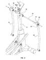
- FIG. 1is an isometric view of an exercise machine including damped joints according to an embodiment of the present disclosure.
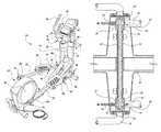
- FIG. 2is an exploded view of a joint assembly of the exercise machine of FIG. 1 .
- FIG. 3is a detail view of the joint assembly of FIG. 2 .
- FIG. 4is a cross-sectional view of the joint assembly of FIG. 2 before the insertion of grease into the joint assembly.
- FIG. 5is a cross-sectional view of the joint assembly of FIG. 2 after the insertion of grease into the joint assembly.
- an exercise device 10may comprise a frame 12 , a drive assembly 14 , foot support members 16 and 18 , swing arms 20 and 22 , and link arms 24 and 26 .
- the drive assembly 14may be mounted at a rear portion of the frame 12 .
- the drive assembly 14may include a first crank arm 26 located on a first side of the drive assembly 14 , and a second crank arm 28 located on an opposing, second side of the drive assembly 14 .
- the first and second crank arms 28 and 30may be coupled to a central rotating member 32 , and the drive assembly 14 may provide selectable resistance to the rotation of the central rotating member 32 by the first and second crank arms 28 and 30 .
- a console 34may be positioned at an upper end of the frame 12 , and the first swing arm 20 may be rotatably coupled to a first side of an upper portion of the frame 14 by a first hinge joint 36 located below the console 34 .
- An upper end of the first swing arm 20may extend above the first hinge joint 36 and may comprise a first handle 38 extending above the console 34 .
- a lower end of the first swing arm 20may extend below the first hinge joint 36 and may be rotatably attached to a first end of a first link arm 24 via a second hinge joint 40 .
- a second end of the first link arm 24may be rotatably attached to the first foot support member 16 via a third hinge joint 42 .
- the second swing arm 22may be rotatably coupled to a second side of the upper portion of the frame 14 by a fourth hinge joint 44 .
- An upper end of the second swing arm 22may extend above the fourth hinge joint 44 and may comprise a second handle 46 .
- a lower end of the second swing arm 22may extend below the fourth hinge joint 44 and may be rotatably attached to a first end of a second link arm 26 via a fifth hinge joint 48 .
- a second end of the second link arm 26may be rotatably attached to the second foot support member 18 via a sixth hinge joint 50 .
- a back end of the first foot support member 16may be rotatably coupled to the first crank arm 28 by a seventh hinge joint 52 . Accordingly, the seventh hinge joint 52 at the back end of the first foot support member 16 may be constrained to movement along a circular path defined by the rotation of the first crank arm 28 about the central rotating member 32 of the drive assembly 14 . Meanwhile, the front end of the first foot support member 16 may be constrained to a movement along an adjustable ramp 54 , which may define a substantially linear path.
- a back end of the second foot support member 18may be rotatably coupled to the second crank arm 30 by an eighth hinge joint 56 . Accordingly, the eighth hinge joint 56 at the back end of the second foot support member 18 may be constrained to movement along a circular path, and the front end of the second foot support member 18 may be constrained to a movement along a linear path defined by the adjustable ramp 54 .
- a first foot pad 58may be coupled to a middle portion of the first foot support member 16
- a second foot pad 60may be coupled to a middle portion of the second foot support member 18 .
- the middle portion of each foot support member 16 and 18may be constrained to movement along an ovoid path (e.g., a path that is non-circular, having the shape of an egg, an oval, or an ellipse).
- Each of the hinge joints 36 , 40 , 42 , 44 , 58 , 50 , 52 , 56may include a first surface of a first component adjacent a second surface of a second component. The first surface and the second surface may define an interface therebetween, and the second surface may be movable relative to the first surface at the interface. At least one of the hinge joints 36 , 40 , 42 , 44 , 58 , 50 , 52 , 56 may include a damping grease 62 (see FIG. 5 ) positioned therein.
- the first and fourth hinge joints 36 and 44 coupling the swing arms 20 and 22 to the frame 12may each include a damping grease 62 positioned therein.
- the first and fourth hinge joints 36 and 44coupling the swing arms 20 and 22 to the frame 12 , may comprise a pin 64 extending through a support tube 66 coupled to the frame 12 .
- each of the first and second swing arms 20 and 22may include a barrel portion 68 including bushings 70 positioned therein.
- the bushings 70may be positioned on the pin 64 , an inner surface 72 of the bushings 70 and an outer surface 74 of the pin 64 may define an interface therebetween where the bushings 70 may rotate relative to the pin 64 .
- the barrel portion 68 of the hinge joint 36 , 44may include a grease fitting 76 located thereon to facilitate the attachment of a grease gun 78 for the insertion of the damping grease 62 into the interface of hinge joint 36 , 44 , as shown in FIGS. 4 and 5 .
- a hinge jointmay not include a grease fitting and damping grease 62 may be packed into the interface of the hinge joint before the hinge joint is fully assembled.
- the damping grease 62 positioned at the interface of at least one of the hinge joints 36 , 40 , 42 , 44 , 58 , 50 , 52 , 56may be a grease having a relatively high viscosity.
- the damping grease 62may have a dynamic viscosity greater than 100 Pascal seconds (Pa ⁇ s) at standard temperature and pressure (STP) (i.e., greater than about one kilopoise at STP).
- the damping grease 62may comprise a synthetic hydrocarbon fluid base and a silica thickener and may have a dynamic viscosity of about 220 Pa ⁇ s at STP (i.e., about 2.2. kilopoise at STP).
- damping grease sold under the tradename ROCOL® KILOPOISE 0868Savailable from ROCOL of Leeds, England, may be a suitable damping grease 62 .
- the properties of the damping grease 62 positioned at the interface of at least one hinge joint 36 , 40 , 42 , 44 , 58 , 50 , 52 , 56 of the exercise device 10 between a first component (e.g., a bushing 70 ) and a second component (e.g., a pin 64 )may resist the sudden movement (i.e., a relatively fast acceleration) of the first component of the at least one hinge joint 36 , 40 , 42 , 44 , 58 , 50 , 52 , 56 relative to the second component of the at least one hinge joint 36 , 40 , 42 , 44 , 58 , 50 , 52 , 56 .
- the damping grease 62may prevent the foot pads 58 and 60 , and other moving components such as the swing arms 20 and 22 , from suddenly moving in response to the force applied by the user's foot. Rather, the foot pad 58 , 60 may provide some resistance to the user's foot and the moving components may start to move relatively slowly. This may provide sufficient time for a user to gain their balance and react to the movement of the foot pads 58 and 60 and swing arms 20 and 22 as the user steps onto the exercise device 10 .
- damping grease 62may provide resistance to relatively fast acceleration of the foot pads 58 and 60 and swing arms 20 and 22
- the damping greasemay provide relatively low resistance to movement of the foot pads 58 and 60 and swing arms 20 and 22 that is associated with relatively slow acceleration, such as during normal exercise on the exercise device 10 .
- ellipticalExercise equipment that provides elliptical foot movement, commonly called “elliptical,” have become very popular. Ellipticals allow a user to simulate walking or running motion for exercise with less impact to the user's body and joints when compared to exercising on a treadmill. Additionally, ellipticals may be less intimidating to users than other equipment, such as treadmills, as the speed of the exercising movement is controlled by the user, rather than an electric motor. Accordingly, there may be less risk of injury when exercising on an elliptical, when compared to exercising on a treadmill.
- the motion of the foot pads of an ellipticalincludes an upward and downward component. Additionally, the foot pads may freely move along the elliptical path, even when the elliptical is not powered on, as the user provides the energy to move the foot pads, rather than an electric motor. Accordingly, when a user steps on to an elliptical the foot pad may move suddenly, especially if the foot pad is not located at the lowest position.
- the sudden movementmay cause the user to lose their balance and fall and/or become injured.
- the linkages of the ellipticalmay cause the sudden movement of one foot pad to swiftly move the other foot pad and the swing arms of the elliptical, which may further off-balance a user and potentially cause an impact between the user and a moving component of the elliptical.
- a usermay be hit by a handle of a swing arm that moves suddenly as the user steps onto a foot pad of an elliptical.
- an exercise devicemay comprise a frame, a drive assembly, foot support members, swing arms, and link arms.
- the drive assemblymay be mounted at a rear portion of the frame.
- the drive assemblymay include a first crank arm located on a first side of the drive assembly, and a second crank arm located on an opposing, second side of the drive assembly.
- the first and second crank armsmay be coupled to a central rotating member, and the drive assembly may provide selectable resistance to the rotation of the central rotating member by the first and second crank arms.
- a consolemay be positioned at an upper end of the frame, and the first swing arm may be rotatably coupled to a first side of an upper portion of the frame by a first hinge joint located below the console.
- An upper end of the first swing armmay extend above the first hinge joint and may comprise a first handle extending above the console.
- a lower end of the first swing armmay extend below the first hinge joint and may be rotatably attached to a first end of a first link arm via a hinge joint.
- a second end of the first link armmay be rotatably attached to the first foot support member via a hinge joint.
- the second swing armmay be rotatably coupled to a second side of the upper portion of the frame by a second hinge joint.
- An upper end of the second swing armmay extend above the second hinge joint and may comprise a second handle.
- a lower end of the second swing armmay extend below the second hinge joint and may be rotatably attached to a first end of a second link arm via a hinge joint.
- a second end of the second link armmay be rotatably attached to the second foot support member via a hinge joint.
- a back end of the first foot support membermay be rotatably coupled to the first crank arm by a hinge joint. Accordingly, the hinge joint at the back end of the first foot support member may be constrained to movement along a circular path defined by the rotation of the first crank arm about the central rotating member of the drive assembly. Meanwhile, the front end of the first foot support member may be constrained to a movement along an adjustable ramp, which may define a substantially linear path.
- a back end of the second foot support membermay be rotatably coupled to the second crank arm by a hinge joint. Accordingly, the hinge joint at the back end of the second foot support member may be constrained to movement along a circular path, and the front end of the first foot support member may be constrained to a movement along a linear path defined by the adjustable ramp.
- a first foot padmay be coupled to a middle portion of the first foot support member, and a second foot pad may be coupled to a middle portion of the second foot support member.
- the middle portion of each foot support membermay be constrained to movement along an ovoid path (e.g., a path that is non-circular, having the shape of an egg, an oval, or an ellipse).
- Each of the hinge jointsmay include a first surface of a first component adjacent a second surface of a second component.
- the first surface and the second surfacemay define an interface therebetween, and the second surface may be movable relative to the first surface at the interface.
- At least one of the hinge jointsmay include a damping grease positioned therein.
- the first and second hinge joints coupling the swing arms to the framemay each include a damping grease positioned therein.
- the first and second hinge joints, coupling the swing arms to the framemay comprise a pin extending through a support tube coupled to the frame.
- Each of the first and second swing armsmay include a barrel portion including bushings positioned therein.
- the bushingsmay be positioned on the pin, an inner surface of the bushings and an outer surface of the pin may define an interface therebetween where the bushings may rotate relative to the pin.
- the barrel portion of the jointmay include a grease fitting located thereon to facilitate the attachment of a grease gun for the insertion of the damping grease into the interface of joint.
- a jointmay not include a grease fitting and damping grease may be packed into the interface of the joint before the joint is fully assembled.
- the damping grease positioned at the interface of at least one of the hinge jointsmay be a grease having a relatively high viscosity.
- the damping greasemay have a dynamic viscosity greater than 100 Pascal seconds (Pa ⁇ s) at standard temperature and pressure (STP) (i.e., greater than about one kilopoise at STP).
- the damping greasemay comprise a synthetic hydrocarbon fluid base and a silica thickener and may have a dynamic viscosity of about 220 Pa ⁇ s at STP (i.e., about 2.2. kilopoise at STP).
- damping grease sold under the tradename ROCOL® KILOPOISE 0868Savailable from ROCOL of Leeds, England, may be a suitable damping grease.
- the properties of the damping grease positioned at the interface of at least one joint of the exercise device between a first component (e.g., a bushing) and a second component (e.g., a pin)may resist the sudden movement (i.e., a relatively fast acceleration) of the first component of the joint relative to the second component of the joint. Accordingly, when a user steps onto a foot pad of the exercise device, the damping grease may prevent the foot pads, and other moving components such as the swing arms, from suddenly moving in response to the force applied by the user's foot. Rather, the foot pad may provide some resistance to the user's foot and the moving components may start to move relatively slowly. This may provide sufficient time for a user to gain their balance and react to the movement of the foot pads and swing arms as the user steps onto the exercise device.
- a first componente.g., a bushing
- a second componente.g., a pin
- the damping greasemay provide resistance to relatively fast acceleration of the foot pads and swing arms
- the damping greasemay provide relatively low resistance to movement of the foot pads and swing arms that is associated with relatively slow acceleration, such as during normal exercise on the exercise device.
Landscapes
- Health & Medical Sciences (AREA)
- General Health & Medical Sciences (AREA)
- Physical Education & Sports Medicine (AREA)
- Cardiology (AREA)
- Vascular Medicine (AREA)
- Engineering & Computer Science (AREA)
- Human Computer Interaction (AREA)
- Life Sciences & Earth Sciences (AREA)
- Biophysics (AREA)
- Orthopedic Medicine & Surgery (AREA)
- Rehabilitation Tools (AREA)
Abstract
Description
Claims (20)
Priority Applications (1)
| Application Number | Priority Date | Filing Date | Title |
|---|---|---|---|
| US15/208,138US9737755B2 (en) | 2012-10-31 | 2016-07-12 | Exercise devices having damped joints and related methods |
Applications Claiming Priority (3)
| Application Number | Priority Date | Filing Date | Title |
|---|---|---|---|
| US201261720893P | 2012-10-31 | 2012-10-31 | |
| US14/068,140US9387387B2 (en) | 2012-10-31 | 2013-10-31 | Exercise devices having damped joints and related methods |
| US15/208,138US9737755B2 (en) | 2012-10-31 | 2016-07-12 | Exercise devices having damped joints and related methods |
Related Parent Applications (1)
| Application Number | Title | Priority Date | Filing Date |
|---|---|---|---|
| US14/068,140ContinuationUS9387387B2 (en) | 2012-10-31 | 2013-10-31 | Exercise devices having damped joints and related methods |
Publications (2)
| Publication Number | Publication Date |
|---|---|
| US20160317861A1 US20160317861A1 (en) | 2016-11-03 |
| US9737755B2true US9737755B2 (en) | 2017-08-22 |
Family
ID=50682267
Family Applications (2)
| Application Number | Title | Priority Date | Filing Date |
|---|---|---|---|
| US14/068,140Active2033-12-03US9387387B2 (en) | 2012-10-31 | 2013-10-31 | Exercise devices having damped joints and related methods |
| US15/208,138ActiveUS9737755B2 (en) | 2012-10-31 | 2016-07-12 | Exercise devices having damped joints and related methods |
Family Applications Before (1)
| Application Number | Title | Priority Date | Filing Date |
|---|---|---|---|
| US14/068,140Active2033-12-03US9387387B2 (en) | 2012-10-31 | 2013-10-31 | Exercise devices having damped joints and related methods |
Country Status (1)
| Country | Link |
|---|---|
| US (2) | US9387387B2 (en) |
Cited By (44)
| Publication number | Priority date | Publication date | Assignee | Title |
|---|---|---|---|---|
| US10279212B2 (en) | 2013-03-14 | 2019-05-07 | Icon Health & Fitness, Inc. | Strength training apparatus with flywheel and related methods |
| US10449416B2 (en) | 2015-08-26 | 2019-10-22 | Icon Health & Fitness, Inc. | Strength exercise mechanisms |
| US10471299B2 (en) | 2016-07-01 | 2019-11-12 | Icon Health & Fitness, Inc. | Systems and methods for cooling internal exercise equipment components |
| US10493349B2 (en) | 2016-03-18 | 2019-12-03 | Icon Health & Fitness, Inc. | Display on exercise device |
| US10500473B2 (en) | 2016-10-10 | 2019-12-10 | Icon Health & Fitness, Inc. | Console positioning |
| US10561893B2 (en) | 2016-10-12 | 2020-02-18 | Icon Health & Fitness, Inc. | Linear bearing for console positioning |
| US10561894B2 (en) | 2016-03-18 | 2020-02-18 | Icon Health & Fitness, Inc. | Treadmill with removable supports |
| US10661114B2 (en) | 2016-11-01 | 2020-05-26 | Icon Health & Fitness, Inc. | Body weight lift mechanism on treadmill |
| US10729965B2 (en) | 2017-12-22 | 2020-08-04 | Icon Health & Fitness, Inc. | Audible belt guide in a treadmill |
| US10758767B2 (en) | 2013-12-26 | 2020-09-01 | Icon Health & Fitness, Inc. | Resistance mechanism in a cable exercise machine |
| US10786706B2 (en) | 2018-07-13 | 2020-09-29 | Icon Health & Fitness, Inc. | Cycling shoe power sensors |
| US10864407B2 (en) | 2016-03-18 | 2020-12-15 | Icon Health & Fitness, Inc. | Coordinated weight selection |
| US10918905B2 (en) | 2016-10-12 | 2021-02-16 | Icon Health & Fitness, Inc. | Systems and methods for reducing runaway resistance on an exercise device |
| US10932517B2 (en) | 2014-03-10 | 2021-03-02 | Icon Health & Fitness, Inc. | Pressure sensor to quantify work |
| US10940360B2 (en) | 2015-08-26 | 2021-03-09 | Icon Health & Fitness, Inc. | Strength exercise mechanisms |
| US10953305B2 (en) | 2015-08-26 | 2021-03-23 | Icon Health & Fitness, Inc. | Strength exercise mechanisms |
| US10994173B2 (en) | 2016-05-13 | 2021-05-04 | Icon Health & Fitness, Inc. | Weight platform treadmill |
| US11000730B2 (en) | 2018-03-16 | 2021-05-11 | Icon Health & Fitness, Inc. | Elliptical exercise machine |
| US11033777B1 (en) | 2019-02-12 | 2021-06-15 | Icon Health & Fitness, Inc. | Stationary exercise machine |
| US11058913B2 (en) | 2017-12-22 | 2021-07-13 | Icon Health & Fitness, Inc. | Inclinable exercise machine |
| US11058914B2 (en) | 2016-07-01 | 2021-07-13 | Icon Health & Fitness, Inc. | Cooling methods for exercise equipment |
| US11187285B2 (en) | 2017-12-09 | 2021-11-30 | Icon Health & Fitness, Inc. | Systems and methods for selectively rotationally fixing a pedaled drivetrain |
| US11298577B2 (en) | 2019-02-11 | 2022-04-12 | Ifit Inc. | Cable and power rack exercise machine |
| US11326673B2 (en) | 2018-06-11 | 2022-05-10 | Ifit Inc. | Increased durability linear actuator |
| US11451108B2 (en) | 2017-08-16 | 2022-09-20 | Ifit Inc. | Systems and methods for axial impact resistance in electric motors |
| US11534651B2 (en) | 2019-08-15 | 2022-12-27 | Ifit Inc. | Adjustable dumbbell system |
| US11534654B2 (en) | 2019-01-25 | 2022-12-27 | Ifit Inc. | Systems and methods for an interactive pedaled exercise device |
| US11673036B2 (en) | 2019-11-12 | 2023-06-13 | Ifit Inc. | Exercise storage system |
| US11794070B2 (en) | 2019-05-23 | 2023-10-24 | Ifit Inc. | Systems and methods for cooling an exercise device |
| US11850497B2 (en) | 2019-10-11 | 2023-12-26 | Ifit Inc. | Modular exercise device |
| US11878199B2 (en) | 2021-02-16 | 2024-01-23 | Ifit Inc. | Safety mechanism for an adjustable dumbbell |
| US11931621B2 (en) | 2020-03-18 | 2024-03-19 | Ifit Inc. | Systems and methods for treadmill drift avoidance |
| US11951377B2 (en) | 2020-03-24 | 2024-04-09 | Ifit Inc. | Leaderboard with irregularity flags in an exercise machine system |
| US12029961B2 (en) | 2020-03-24 | 2024-07-09 | Ifit Inc. | Flagging irregularities in user performance in an exercise machine system |
| US12029935B2 (en) | 2021-08-19 | 2024-07-09 | Ifit Inc. | Adjustment mechanism for an adjustable kettlebell |
| US20240288030A1 (en)* | 2023-02-27 | 2024-08-29 | Life Fitness, Llc | Pivot devices for exercise equipment |
| US12176009B2 (en) | 2021-12-30 | 2024-12-24 | Ifit Inc. | Systems and methods for synchronizing workout equipment with video files |
| US12219201B2 (en) | 2021-08-05 | 2025-02-04 | Ifit Inc. | Synchronizing video workout programs across multiple devices |
| US12263371B2 (en) | 2021-04-27 | 2025-04-01 | Ifit Inc. | Devices, systems, and methods for rotating a tread belt in two directions |
| US12280294B2 (en) | 2021-10-15 | 2025-04-22 | Ifit Inc. | Magnetic clutch for a pedaled drivetrain |
| US12350573B2 (en) | 2021-04-27 | 2025-07-08 | Ifit Inc. | Systems and methods for cross-training on exercise devices |
| US12350547B2 (en) | 2022-02-28 | 2025-07-08 | Ifit Inc. | Devices, systems, and methods for moving a movable step through a transition zone |
| US12409375B2 (en) | 2022-03-18 | 2025-09-09 | Ifit Inc. | Systems and methods for haptic simulation in incline exercise devices |
| US12433815B2 (en) | 2020-10-02 | 2025-10-07 | Ifit Inc. | Massage roller with pressure sensors |
Families Citing this family (14)
| Publication number | Priority date | Publication date | Assignee | Title |
|---|---|---|---|---|
| US9345948B2 (en) | 2012-10-19 | 2016-05-24 | Todd Martin | System for providing a coach with live training data of an athlete as the athlete is training |
| US9387387B2 (en)* | 2012-10-31 | 2016-07-12 | Icon Health & Fitness, Inc. | Exercise devices having damped joints and related methods |
| WO2015191445A1 (en) | 2014-06-09 | 2015-12-17 | Icon Health & Fitness, Inc. | Cable system incorporated into a treadmill |
| US10258828B2 (en) | 2015-01-16 | 2019-04-16 | Icon Health & Fitness, Inc. | Controls for an exercise device |
| CN107921308B (en)* | 2015-08-28 | 2020-04-10 | 爱康保健健身有限公司 | Sleeve in body-building apparatus |
| US10625137B2 (en) | 2016-03-18 | 2020-04-21 | Icon Health & Fitness, Inc. | Coordinated displays in an exercise device |
| US10272317B2 (en) | 2016-03-18 | 2019-04-30 | Icon Health & Fitness, Inc. | Lighted pace feature in a treadmill |
| US10441844B2 (en) | 2016-07-01 | 2019-10-15 | Icon Health & Fitness, Inc. | Cooling systems and methods for exercise equipment |
| US10376736B2 (en) | 2016-10-12 | 2019-08-13 | Icon Health & Fitness, Inc. | Cooling an exercise device during a dive motor runway condition |
| US10207148B2 (en) | 2016-10-12 | 2019-02-19 | Icon Health & Fitness, Inc. | Systems and methods for reducing runaway resistance on an exercise device |
| TWI646997B (en) | 2016-11-01 | 2019-01-11 | 美商愛康運動與健康公司 | Distance sensor for console positioning |
| US10625114B2 (en) | 2016-11-01 | 2020-04-21 | Icon Health & Fitness, Inc. | Elliptical and stationary bicycle apparatus including row functionality |
| TWI680782B (en) | 2016-12-05 | 2020-01-01 | 美商愛康運動與健康公司 | Offsetting treadmill deck weight during operation |
| CN109289190A (en)* | 2018-11-09 | 2019-02-01 | 北京石油化工学院 | A device that displays the amount of exercise |
Citations (14)
| Publication number | Priority date | Publication date | Assignee | Title |
|---|---|---|---|---|
| US3072426A (en) | 1960-09-30 | 1963-01-08 | Swivelier Company Inc | Swivel unit having split ball |
| US4324501A (en) | 1979-10-05 | 1982-04-13 | Trw Inc. | Joint assembly |
| US4499784A (en) | 1981-11-20 | 1985-02-19 | Westinghouse Electric Corp. | Split-ball type wrist and manipulating assembly for robot |
| US4928546A (en) | 1988-08-17 | 1990-05-29 | Walters David A | Robotic devices |
| US5568993A (en) | 1994-12-21 | 1996-10-29 | The United States Of America As Represented By The Secretary Of Commerce | Strut structure and rigid joint therefor |
| US6071031A (en) | 1994-12-05 | 2000-06-06 | Hexel Corporation | Movable mechanical structures |
| US6315486B1 (en) | 1997-03-15 | 2001-11-13 | Ina Walzlager Schaeffler Ohg | Joint mounted on rolling bearings |
| US6671975B2 (en) | 2001-12-10 | 2004-01-06 | C. William Hennessey | Parallel kinematic micromanipulator |
| US7290760B1 (en) | 2006-11-10 | 2007-11-06 | Steven James Lindsay | Rotating, positioning and tilting mechanism with cam locks |
| US7475613B2 (en) | 2000-10-26 | 2009-01-13 | Shin Nippon Koki Co., Ltd. | Multi-axis spindle head |
| US7604573B2 (en) | 2005-04-14 | 2009-10-20 | Icon Ip, Inc. | Method and system for varying stride in an elliptical exercise machine |
| US8449620B2 (en) | 2007-11-07 | 2013-05-28 | Gs Development Ab | Artificial joint |
| US9015952B2 (en) | 2010-11-19 | 2015-04-28 | Sumitomo Precision Products Co., Ltd. | Six-direction directing device |
| US9387387B2 (en)* | 2012-10-31 | 2016-07-12 | Icon Health & Fitness, Inc. | Exercise devices having damped joints and related methods |
- 2013
- 2013-10-31USUS14/068,140patent/US9387387B2/enactiveActive
- 2016
- 2016-07-12USUS15/208,138patent/US9737755B2/enactiveActive
Patent Citations (15)
| Publication number | Priority date | Publication date | Assignee | Title |
|---|---|---|---|---|
| US3072426A (en) | 1960-09-30 | 1963-01-08 | Swivelier Company Inc | Swivel unit having split ball |
| US4324501A (en) | 1979-10-05 | 1982-04-13 | Trw Inc. | Joint assembly |
| US4499784A (en) | 1981-11-20 | 1985-02-19 | Westinghouse Electric Corp. | Split-ball type wrist and manipulating assembly for robot |
| US4928546A (en) | 1988-08-17 | 1990-05-29 | Walters David A | Robotic devices |
| US6071031A (en) | 1994-12-05 | 2000-06-06 | Hexel Corporation | Movable mechanical structures |
| US5568993A (en) | 1994-12-21 | 1996-10-29 | The United States Of America As Represented By The Secretary Of Commerce | Strut structure and rigid joint therefor |
| US6315486B1 (en) | 1997-03-15 | 2001-11-13 | Ina Walzlager Schaeffler Ohg | Joint mounted on rolling bearings |
| US7475613B2 (en) | 2000-10-26 | 2009-01-13 | Shin Nippon Koki Co., Ltd. | Multi-axis spindle head |
| US6671975B2 (en) | 2001-12-10 | 2004-01-06 | C. William Hennessey | Parallel kinematic micromanipulator |
| US6769194B2 (en) | 2001-12-10 | 2004-08-03 | C. William Hennessey | Parallel kinematic micromanipulator |
| US7604573B2 (en) | 2005-04-14 | 2009-10-20 | Icon Ip, Inc. | Method and system for varying stride in an elliptical exercise machine |
| US7290760B1 (en) | 2006-11-10 | 2007-11-06 | Steven James Lindsay | Rotating, positioning and tilting mechanism with cam locks |
| US8449620B2 (en) | 2007-11-07 | 2013-05-28 | Gs Development Ab | Artificial joint |
| US9015952B2 (en) | 2010-11-19 | 2015-04-28 | Sumitomo Precision Products Co., Ltd. | Six-direction directing device |
| US9387387B2 (en)* | 2012-10-31 | 2016-07-12 | Icon Health & Fitness, Inc. | Exercise devices having damped joints and related methods |
Cited By (69)
| Publication number | Priority date | Publication date | Assignee | Title |
|---|---|---|---|---|
| US11878206B2 (en) | 2013-03-14 | 2024-01-23 | Ifit Inc. | Strength training apparatus |
| US10279212B2 (en) | 2013-03-14 | 2019-05-07 | Icon Health & Fitness, Inc. | Strength training apparatus with flywheel and related methods |
| US11338169B2 (en) | 2013-03-14 | 2022-05-24 | IFIT, Inc. | Strength training apparatus |
| US10709925B2 (en) | 2013-03-14 | 2020-07-14 | Icon Health & Fitness, Inc. | Strength training apparatus |
| US10953268B1 (en) | 2013-03-14 | 2021-03-23 | Icon Health & Fitness, Inc. | Strength training apparatus |
| US10967214B1 (en) | 2013-12-26 | 2021-04-06 | Icon Health & Fitness, Inc. | Cable exercise machine |
| US10758767B2 (en) | 2013-12-26 | 2020-09-01 | Icon Health & Fitness, Inc. | Resistance mechanism in a cable exercise machine |
| US10932517B2 (en) | 2014-03-10 | 2021-03-02 | Icon Health & Fitness, Inc. | Pressure sensor to quantify work |
| US11700905B2 (en) | 2014-03-10 | 2023-07-18 | Ifit Inc. | Pressure sensor to quantify work |
| US10449416B2 (en) | 2015-08-26 | 2019-10-22 | Icon Health & Fitness, Inc. | Strength exercise mechanisms |
| US10953305B2 (en) | 2015-08-26 | 2021-03-23 | Icon Health & Fitness, Inc. | Strength exercise mechanisms |
| US10940360B2 (en) | 2015-08-26 | 2021-03-09 | Icon Health & Fitness, Inc. | Strength exercise mechanisms |
| US12023549B2 (en) | 2016-03-18 | 2024-07-02 | Ifit Inc. | Stationary exercise machine configured to execute a programmed workout with aerobic portions and lifting portions |
| US12029943B2 (en) | 2016-03-18 | 2024-07-09 | Ifit Inc. | Stationary exercise machine configured to execute a programmed workout with aerobic portions and lifting portions |
| US10864407B2 (en) | 2016-03-18 | 2020-12-15 | Icon Health & Fitness, Inc. | Coordinated weight selection |
| US11565148B2 (en) | 2016-03-18 | 2023-01-31 | Ifit Inc. | Treadmill with a scale mechanism in a motor cover |
| US11794075B2 (en) | 2016-03-18 | 2023-10-24 | Ifit Inc. | Stationary exercise machine configured to execute a programmed workout with aerobic portions and lifting portions |
| US10561894B2 (en) | 2016-03-18 | 2020-02-18 | Icon Health & Fitness, Inc. | Treadmill with removable supports |
| US10493349B2 (en) | 2016-03-18 | 2019-12-03 | Icon Health & Fitness, Inc. | Display on exercise device |
| US11013960B2 (en) | 2016-03-18 | 2021-05-25 | Icon Health & Fitness, Inc. | Exercise system including a stationary bicycle and a free weight cradle |
| US12029944B2 (en) | 2016-03-18 | 2024-07-09 | Ifit Inc. | Stationary exercise machine configured to execute a programmed workout with aerobic portions and lifting portions |
| US11779812B2 (en) | 2016-05-13 | 2023-10-10 | Ifit Inc. | Treadmill configured to automatically determine user exercise movement |
| US10994173B2 (en) | 2016-05-13 | 2021-05-04 | Icon Health & Fitness, Inc. | Weight platform treadmill |
| US11058914B2 (en) | 2016-07-01 | 2021-07-13 | Icon Health & Fitness, Inc. | Cooling methods for exercise equipment |
| US10471299B2 (en) | 2016-07-01 | 2019-11-12 | Icon Health & Fitness, Inc. | Systems and methods for cooling internal exercise equipment components |
| US10500473B2 (en) | 2016-10-10 | 2019-12-10 | Icon Health & Fitness, Inc. | Console positioning |
| US10561893B2 (en) | 2016-10-12 | 2020-02-18 | Icon Health & Fitness, Inc. | Linear bearing for console positioning |
| US10918905B2 (en) | 2016-10-12 | 2021-02-16 | Icon Health & Fitness, Inc. | Systems and methods for reducing runaway resistance on an exercise device |
| US10661114B2 (en) | 2016-11-01 | 2020-05-26 | Icon Health & Fitness, Inc. | Body weight lift mechanism on treadmill |
| US11451108B2 (en) | 2017-08-16 | 2022-09-20 | Ifit Inc. | Systems and methods for axial impact resistance in electric motors |
| US11680611B2 (en) | 2017-12-09 | 2023-06-20 | Ifit Inc. | Systems and methods for selectively rotationally fixing a pedaled drivetrain |
| US12270441B2 (en) | 2017-12-09 | 2025-04-08 | Ifit Inc. | Systems and methods for selectively rotationally fixing a pedaled drivetrain |
| US11708874B2 (en) | 2017-12-09 | 2023-07-25 | Ifit Inc. | Systems and methods for selectively rotationally fixing a pedaled drivetrain |
| US11187285B2 (en) | 2017-12-09 | 2021-11-30 | Icon Health & Fitness, Inc. | Systems and methods for selectively rotationally fixing a pedaled drivetrain |
| US11058913B2 (en) | 2017-12-22 | 2021-07-13 | Icon Health & Fitness, Inc. | Inclinable exercise machine |
| US10729965B2 (en) | 2017-12-22 | 2020-08-04 | Icon Health & Fitness, Inc. | Audible belt guide in a treadmill |
| US11000730B2 (en) | 2018-03-16 | 2021-05-11 | Icon Health & Fitness, Inc. | Elliptical exercise machine |
| US11596830B2 (en) | 2018-03-16 | 2023-03-07 | Ifit Inc. | Elliptical exercise machine |
| US11326673B2 (en) | 2018-06-11 | 2022-05-10 | Ifit Inc. | Increased durability linear actuator |
| US12005315B2 (en) | 2018-07-13 | 2024-06-11 | Ifit Inc. | Cycling shoe power sensors |
| US10786706B2 (en) | 2018-07-13 | 2020-09-29 | Icon Health & Fitness, Inc. | Cycling shoe power sensors |
| US11534654B2 (en) | 2019-01-25 | 2022-12-27 | Ifit Inc. | Systems and methods for an interactive pedaled exercise device |
| US11642564B2 (en) | 2019-02-11 | 2023-05-09 | Ifit Inc. | Exercise machine |
| US11452903B2 (en) | 2019-02-11 | 2022-09-27 | Ifit Inc. | Exercise machine |
| US11298577B2 (en) | 2019-02-11 | 2022-04-12 | Ifit Inc. | Cable and power rack exercise machine |
| US11951358B2 (en) | 2019-02-12 | 2024-04-09 | Ifit Inc. | Encoding exercise machine control commands in subtitle streams |
| US11033777B1 (en) | 2019-02-12 | 2021-06-15 | Icon Health & Fitness, Inc. | Stationary exercise machine |
| US11058918B1 (en) | 2019-02-12 | 2021-07-13 | Icon Health & Fitness, Inc. | Producing a workout video to control a stationary exercise machine |
| US11426633B2 (en) | 2019-02-12 | 2022-08-30 | Ifit Inc. | Controlling an exercise machine using a video workout program |
| US11794070B2 (en) | 2019-05-23 | 2023-10-24 | Ifit Inc. | Systems and methods for cooling an exercise device |
| US11534651B2 (en) | 2019-08-15 | 2022-12-27 | Ifit Inc. | Adjustable dumbbell system |
| US11850497B2 (en) | 2019-10-11 | 2023-12-26 | Ifit Inc. | Modular exercise device |
| US12296247B2 (en) | 2019-10-11 | 2025-05-13 | Ifit Inc. | Modular exercise device |
| US11673036B2 (en) | 2019-11-12 | 2023-06-13 | Ifit Inc. | Exercise storage system |
| US11931621B2 (en) | 2020-03-18 | 2024-03-19 | Ifit Inc. | Systems and methods for treadmill drift avoidance |
| US11951377B2 (en) | 2020-03-24 | 2024-04-09 | Ifit Inc. | Leaderboard with irregularity flags in an exercise machine system |
| US12029961B2 (en) | 2020-03-24 | 2024-07-09 | Ifit Inc. | Flagging irregularities in user performance in an exercise machine system |
| US12433815B2 (en) | 2020-10-02 | 2025-10-07 | Ifit Inc. | Massage roller with pressure sensors |
| US11878199B2 (en) | 2021-02-16 | 2024-01-23 | Ifit Inc. | Safety mechanism for an adjustable dumbbell |
| US12239872B2 (en) | 2021-02-16 | 2025-03-04 | Ifit Inc. | Safety mechanism for an adjustable dumbbell |
| US12263371B2 (en) | 2021-04-27 | 2025-04-01 | Ifit Inc. | Devices, systems, and methods for rotating a tread belt in two directions |
| US12350573B2 (en) | 2021-04-27 | 2025-07-08 | Ifit Inc. | Systems and methods for cross-training on exercise devices |
| US12219201B2 (en) | 2021-08-05 | 2025-02-04 | Ifit Inc. | Synchronizing video workout programs across multiple devices |
| US12029935B2 (en) | 2021-08-19 | 2024-07-09 | Ifit Inc. | Adjustment mechanism for an adjustable kettlebell |
| US12280294B2 (en) | 2021-10-15 | 2025-04-22 | Ifit Inc. | Magnetic clutch for a pedaled drivetrain |
| US12176009B2 (en) | 2021-12-30 | 2024-12-24 | Ifit Inc. | Systems and methods for synchronizing workout equipment with video files |
| US12350547B2 (en) | 2022-02-28 | 2025-07-08 | Ifit Inc. | Devices, systems, and methods for moving a movable step through a transition zone |
| US12409375B2 (en) | 2022-03-18 | 2025-09-09 | Ifit Inc. | Systems and methods for haptic simulation in incline exercise devices |
| US20240288030A1 (en)* | 2023-02-27 | 2024-08-29 | Life Fitness, Llc | Pivot devices for exercise equipment |
Also Published As
| Publication number | Publication date |
|---|---|
| US20140135180A1 (en) | 2014-05-15 |
| US9387387B2 (en) | 2016-07-12 |
| US20160317861A1 (en) | 2016-11-03 |
Similar Documents
| Publication | Publication Date | Title |
|---|---|---|
| US9737755B2 (en) | Exercise devices having damped joints and related methods | |
| US8979720B2 (en) | Strength and balance exercise apparatus | |
| CN107921308B (en) | Sleeve in body-building apparatus | |
| US10350451B2 (en) | Exercise device | |
| US7833133B2 (en) | End of travel stop for an exercise device | |
| JP5319110B2 (en) | Auxiliary resistance assembly for resisting movement of exercise equipment | |
| CN210228999U (en) | Passive balance training evaluation device | |
| CN107185161B (en) | Pedal assembly and fitness equipment | |
| US20070027001A1 (en) | Gymnastic machine | |
| JP2014507239A5 (en) | ||
| US7918767B1 (en) | Exercise apparatus | |
| CA2661469A1 (en) | Leg rehabilitation apparatus | |
| EP3485862B1 (en) | Interacting exercise device | |
| TWI576139B (en) | Reciprocating Bouncing Machine and Its Buffering Energy Saving Method | |
| CN107101841B (en) | Durability test device for treadmill | |
| CN201949549U (en) | Anti-vibration mechanism and treadmill structure with the anti-vibration mechanism | |
| CN112604236A (en) | Lower limb bouncing force nuclear power trainer | |
| CN202015449U (en) | Dancing machine | |
| US20120252639A1 (en) | Apparatus and Method for Exercising a User's Muscles | |
| KR20210071574A (en) | Horse riding type thigh exercising apparatus | |
| CN106390382B (en) | Stand up device and the recovery exercising robot with it of recovery exercising robot | |
| CN220090387U (en) | Rear leg lifting training device | |
| CN215691358U (en) | Space treadmill | |
| KR101225258B1 (en) | Rotation exercise equipment | |
| CN106890427B (en) | Exercise apparatus |
Legal Events
| Date | Code | Title | Description |
|---|---|---|---|
| STCF | Information on status: patent grant | Free format text:PATENTED CASE | |
| AS | Assignment | Owner name:JPMORGAN CHASE BANK, N.A., AS ADMINISTRATIVE AGENT, ILLINOIS Free format text:PATENT SECURITY AGREEMENT;ASSIGNOR:ICON HEALTH & FITNESS, INC.;REEL/FRAME:053548/0453 Effective date:20200427 | |
| MAFP | Maintenance fee payment | Free format text:PAYMENT OF MAINTENANCE FEE, 4TH YEAR, LARGE ENTITY (ORIGINAL EVENT CODE: M1551); ENTITY STATUS OF PATENT OWNER: LARGE ENTITY Year of fee payment:4 | |
| AS | Assignment | Owner name:BANK OF AMERICA, N.A., AS ADMINISTRATIVE AGENT, CALIFORNIA Free format text:SECURITY INTEREST;ASSIGNOR:ICON HEALTH & FITNESS, INC.;REEL/FRAME:056238/0818 Effective date:20210512 | |
| AS | Assignment | Owner name:ICON HEALTH & FITNESS, INC., UTAH Free format text:TERMINATION AND RELEASE OF SECURITY INTEREST IN PATENTS;ASSIGNOR:JPMORGAN CHASE BANK, N.A., AS ADMINISTRATIVE AGENT;REEL/FRAME:056654/0951 Effective date:20210512 | |
| AS | Assignment | Owner name:IFIT INC, UTAH Free format text:CHANGE OF NAME;ASSIGNOR:ICON HEALTH & FITNESS, INC.;REEL/FRAME:058742/0476 Effective date:20210809 | |
| AS | Assignment | Owner name:IFIT INC., UTAH Free format text:TO CORRECT AN ERROR IN A COVER SHEET PREVIOUSLY RECORDED AT REEL/FRAME 058742/0476 - CORRECT ASSIGNEE NAME IFIT INC TO IFIT INC;ASSIGNOR:ICON HEALTH & FITNESS, INC.;REEL/FRAME:058957/0531 Effective date:20210809 | |
| AS | Assignment | Owner name:PLC AGENT LLC, MASSACHUSETTS Free format text:SECURITY INTEREST;ASSIGNOR:IFIT INC.;REEL/FRAME:059249/0466 Effective date:20220224 | |
| AS | Assignment | Owner name:ICON PREFERRED HOLDINGS, L.P., UTAH Free format text:INTELLECTUAL PROPERTY SECURITY AGREEMENT;ASSIGNOR:IFIT INC.;REEL/FRAME:059633/0313 Effective date:20220224 | |
| AS | Assignment | Owner name:ICON PREFERRED HOLDINGS, L.P., NEW YORK Free format text:CORRECTIVE ASSIGNMENT TO CORRECT THE THE ASSIGNEE'S ADDRESS PREVIOUSLY RECORDED AT REEL: 059633 FRAME: 0313. ASSIGNOR(S) HEREBY CONFIRMS THE ASSIGNMENT;ASSIGNOR:IFIT INC.;REEL/FRAME:060512/0315 Effective date:20220224 | |
| AS | Assignment | Owner name:LC9 CONNECTED HOLDINGS, LP, CONNECTICUT Free format text:SECURITY INTEREST;ASSIGNORS:IFIT INC.;ICON IP, INC.;REEL/FRAME:059857/0830 Effective date:20220224 | |
| AS | Assignment | Owner name:LC9 CONNECTED HOLDINGS, LP, CONNECTICUT Free format text:SECURITY INTEREST;ASSIGNORS:IFIT INC.;ICON IP, INC.;REEL/FRAME:066094/0529 Effective date:20231214 | |
| MAFP | Maintenance fee payment | Free format text:PAYMENT OF MAINTENANCE FEE, 8TH YEAR, LARGE ENTITY (ORIGINAL EVENT CODE: M1552); ENTITY STATUS OF PATENT OWNER: LARGE ENTITY Year of fee payment:8 | |
| AS | Assignment | Owner name:CERBERUS BUSINESS FINANCE AGENCY, LLC, NEW YORK Free format text:SECURITY INTEREST;ASSIGNOR:IFIT, INC.;REEL/FRAME:071278/0707 Effective date:20250512 | |
| AS | Assignment | Owner name:ICON IP INC., UTAH Free format text:RELEASE BY SECURED PARTY;ASSIGNOR:ICON PREFERRED HOLDINGS, L.P.;REEL/FRAME:071336/0725 Effective date:20250512 Owner name:IFIT INC., UTAH Free format text:RELEASE BY SECURED PARTY;ASSIGNOR:ICON PREFERRED HOLDINGS, L.P.;REEL/FRAME:071336/0725 Effective date:20250512 | |
| AS | Assignment | Owner name:ICON IP, INC., UTAH Free format text:RELEASE BY SECURED PARTY;ASSIGNOR:BANK OF AMERICA, N.A.;REEL/FRAME:071351/0624 Effective date:20250512 Owner name:IFIT, INC. (F/K/A ICON HEALTH & FITNESS, INC.), UTAH Free format text:RELEASE BY SECURED PARTY;ASSIGNOR:BANK OF AMERICA, N.A.;REEL/FRAME:071351/0624 Effective date:20250512 Owner name:ICON IP, INC., UTAH Free format text:RELEASE BY SECURED PARTY;ASSIGNOR:PLC AGENT LLC;REEL/FRAME:071358/0584 Effective date:20250512 Owner name:IFIT INC., UTAH Free format text:RELEASE BY SECURED PARTY;ASSIGNOR:PLC AGENT LLC;REEL/FRAME:071358/0584 Effective date:20250512 | |
| AS | Assignment | Owner name:ICON IP INC., UTAH Free format text:RELEASE BY SECURED PARTY;ASSIGNOR:LC9 CONNECTED HOLDINGS, LP;REEL/FRAME:071407/0001 Effective date:20250512 Owner name:IFIT INC., UTAH Free format text:RELEASE BY SECURED PARTY;ASSIGNOR:LC9 CONNECTED HOLDINGS, LP;REEL/FRAME:071407/0001 Effective date:20250512 | |
| AS | Assignment | Owner name:ICON IP INC., UTAH Free format text:RELEASE OF INTELLECTUAL PROPERTY SECURITY INTEREST (4TH LIEN);ASSIGNOR:LC9 CONNECTED HOLDINGS, LP;REEL/FRAME:071429/0479 Effective date:20250512 Owner name:IFIT INC., UTAH Free format text:RELEASE OF INTELLECTUAL PROPERTY SECURITY INTEREST (4TH LIEN);ASSIGNOR:LC9 CONNECTED HOLDINGS, LP;REEL/FRAME:071429/0479 Effective date:20250512 |